

Page 1

MARSIC300
Ship Emission Measuring Device
Installation and Initial Start-up
T E C H N I C A L I N F O R M A T I O N
Page 2

Described product
MARSIC300
Manufacturer
SICK AG
Erwin-Sick-Str. 1
79183 Waldkirch
Germany
Legal information
This work is protected by copyright. Any rights derived from the copyright shall be
reserved for SICK AG. Reproduction of this document or parts of this document is only
permissible within the limits of the legal determination of Copyright Law. Any modifica‐
tion, abridgment or translation of this document is prohibited without the express writ‐
ten permission of SICK AG.
The trademarks stated in this document are the property of their respective owner.
© SICK AG. All rights reserved.
Original document
This document is an original document of SICK AG.
2
T EC H NI C AL IN F OR M AT I ON | MARSIC300 8017585/YXD9/V3-1/2017-05 | SICK
Subject to change without notice
Page 3

Contents
CONTENTS
1 About this document........................................................................ 6
1.1 Function of this document....................................................................... 6
1.2 Target group.............................................................................................. 6
1.3 Further information................................................................................... 6
1.4 Symbols and document conventions...................................................... 6
1.4.1 Warning symbols...................................................................... 6
1.4.2 Warning levels / Signal words................................................. 7
1.4.3 Information symbols................................................................ 7
2 Installation.......................................................................................... 8
2.1 Gas supply terminology............................................................................ 8
2.2 Installation information............................................................................ 8
2.2.1 Information on power supply.................................................. 8
2.2.2 Notes on the gas supply.......................................................... 8
2.2.3 Tube screw fitting..................................................................... 9
2.3 Scope of delivery....................................................................................... 9
2.4 Provision by operator................................................................................ 9
2.5 Installation overview................................................................................. 10
2.6 Checklist for mechanical and electrical installation............................... 10
2.7 Assembly information for sample gas lines and tube bundle cable..... 11
2.8 Installing the analyzer cabinet................................................................. 13
2.9 Connect the sample gas line to the analyzer.......................................... 14
2.10 Connecting the tube bundle cable to the analyzer................................. 16
2.11 Connecting the signal lines to the analyzer............................................ 19
2.12 Air and gas connections on analyzer....................................................... 20
2.13 Electrical connections on the analyzer.................................................... 23
2.14 Installing the gas sampling system......................................................... 25
2.15 Setting up the Modbus-Profinet converter (optional)............................. 27
2.16 Setting up the Modbus-Profinet converter (optional)............................. 32
3 Initial start-up..................................................................................... 37
4 Configuration software..................................................................... 39
4.1 Software SOPAS ET................................................................................... 39
4.2 Saving parameters.................................................................................... 40
4.3 Backing up the logbook with SOPAS ET.................................................. 41
4.4 Passwords................................................................................................. 41
4.5 Using the menus....................................................................................... 42
4.6 Menu tree (SOPAS ET).............................................................................. 42
5 Measuring screens and data storage............................................. 44
5.1 Measuring screen..................................................................................... 44
5.2 Data storage function............................................................................... 45
6 Parameterization............................................................................... 47
8017585/YXD9/V3-1/2017-05 | SICK T EC H NI C AL IN F OR M AT I ON | MARSIC300
Subject to change without notice
3
Page 4

CONTENTS
6.1 Measuring components............................................................................ 47
6.2 Measuring screens................................................................................... 47
6.3 Adjustment functions............................................................................... 50
6.3.1.1 Concentrations of test gases................................. 51
6.3.1.2 Adjustment factors................................................. 51
6.3.1.3 Start times.............................................................. 51
6.3.1 Manual adjustment................................................................. 52
6.3.2 Automatic adjustment............................................................. 52
6.4 Measuring point switchover / Sequence control program..................... 52
6.5 Data interfaces / IO.................................................................................. 55
6.5.1 Digital inputs............................................................................ 55
6.5.2 Digital outputs.......................................................................... 56
6.5.3 OPC outputs............................................................................. 56
6.5.4 Modbus..................................................................................... 56
6.6 Device parameters................................................................................... 58
6.6.1 Temperature control................................................................ 58
6.6.2 Pressure control....................................................................... 59
6.6.3 Flow rate................................................................................... 59
6.6.4 O2 sensor................................................................................. 59
6.6.5 Logbook.................................................................................... 59
6.6.6 Instrument display................................................................... 60
6.6.7 System ..................................................................................... 60
6.6.8 Emitter...................................................................................... 61
7 Diagnosis............................................................................................ 62
7.1 Control values adjustment, sensors and signals.................................... 62
7.2 Sensor values........................................................................................... 63
7.3 Signals....................................................................................................... 63
7.4 Logbook..................................................................................................... 66
7.5 System info................................................................................................ 67
7.5.1 System status.......................................................................... 68
7.5.2 System info............................................................................... 68
7.5.3 Timemeter................................................................................ 68
8 Maintenance...................................................................................... 69
8.1 Test digital I/O........................................................................................... 69
8.2 Setting operating states........................................................................... 69
8.3 System maintenance (Stand-by, Leakage test, etc.).............................. 70
8.4 Restart....................................................................................................... 71
8.5 Service log................................................................................................. 71
8.6 Acknowledging messages........................................................................ 72
8.7 Loading/saving the parameters.............................................................. 72
8.8 Loading/saving the parameters after replacing the analyzer................ 73
8.9 Loading/saving the parameters after replacing the electronics........... 74
9 Maintenance...................................................................................... 75
4
T EC H NI C AL IN F OR M AT I ON | MARSIC300 8017585/YXD9/V3-1/2017-05 | SICK
Subject to change without notice
Page 5

CONTENTS
9.1 Leak tightness check during initial startup............................................. 75
9.2 Leak tightness check with pressure test tool......................................... 76
10 Technical data.................................................................................... 78
10.1 Dimensional drawings.............................................................................. 78
10.2 Design........................................................................................................ 79
10.3 Measuring parameters............................................................................. 79
10.4 Ambient conditions................................................................................... 80
10.5 Sample gas conditions............................................................................. 80
10.6 Heated sample gas lines.......................................................................... 81
10.7 Tube bundle cable.................................................................................... 81
10.8 Interfaces and protocols.......................................................................... 82
10.9 Power supply............................................................................................. 82
10.10 Connections in analyzer........................................................................... 83
10.11 Circuit breakers......................................................................................... 86
10.12 Supply gases............................................................................................. 87
10.13 Tube connections...................................................................................... 87
10.14 Torques...................................................................................................... 87
11 Annex.................................................................................................. 89
11.1 Gas flow plan............................................................................................ 89
11.2 Modbus register........................................................................................ 90
11.2.1 Device status (Discrete Inputs [1xxxx], Function Code 02)... 90
11.2.2 Measured variables (Input Register [3xxxx], Function Code
04)............................................................................................ 90
11.2.3 Device-internal monitoring values (Input Register [3xxxx],
Function Code 04)................................................................... 91
11.2.4 Triggering the MARSIC 300 (Coils [0xxxx], Function Code
15, write multiple Coils).......................................................... 92
11.2.5 VDI 4301 conform range (Holding Register [4xxxx], Func‐
tion Code 03)........................................................................... 92
11.3 Error messages and possible causes..................................................... 93
11.4 Tags (variable names).............................................................................. 100
12 Index.................................................................................................... 102
8017585/YXD9/V3-1/2017-05 | SICK T EC H NI C AL IN F OR M AT I ON | MARSIC300
Subject to change without notice
5
Page 6
1 ABOUT THIS DOCUMENT
1 About this document
1.1 Function of this document
This document describes:
Installation
•
Initial start-up
•
Operation via SOPAS ET
•
NOTICE
This technical documentation is only valid in combination with the MARSIC300 Operat‐
ing Instructions.
1.2 Target group
This document is addressed to technicians (persons with technical understanding)
operating and maintaining the measuring system.
The technicians must have been trained on the device.
Requirements for the technician
The technician must be familiar with the exhaust gas technology on the ship (over‐
•
pressure, toxic and hot flue gases) and be able to avoid hazards when working on
gas ducts.
The technician must be familiar with handling compressed gas cylinders (test
•
gases).
The technician must be able to avoid hazards caused by noxious test gases.
•
Only allow an authorized electrician to work on the electrical system or electrical
•
subassemblies.
1.3 Further information
SFU Gas Sampling System Operating Instructions
•
Sample Gas Line Operating Instructions
•
System documentation
•
Short instructions for MARSIC300
•
Optional: MPR (Meeting Point Router) Operating Instructions
•
Optional: Instrument Air Conditioning Operating Instructions
•
Optional: External Measuring Point Switchover Operating Instructions
•
Optional: Pressure Test Tool Operating Instructions
•
Optional: Profibus/Profinet Converter Operating Instructions
•
Optional: HOTSAMPLER (measuring point extension) Operating Instructions
•
1.4 Symbols and document conventions
1.4.1 Warning symbols
Table 1: Warning symbols
Symbol Significance
6
T EC H NI C AL IN F OR M AT I ON | MARSIC300 8017585/YXD9/V3-1/2017-05 | SICK
Hazard (general)
Hazard by voltage
Subject to change without notice
Page 7
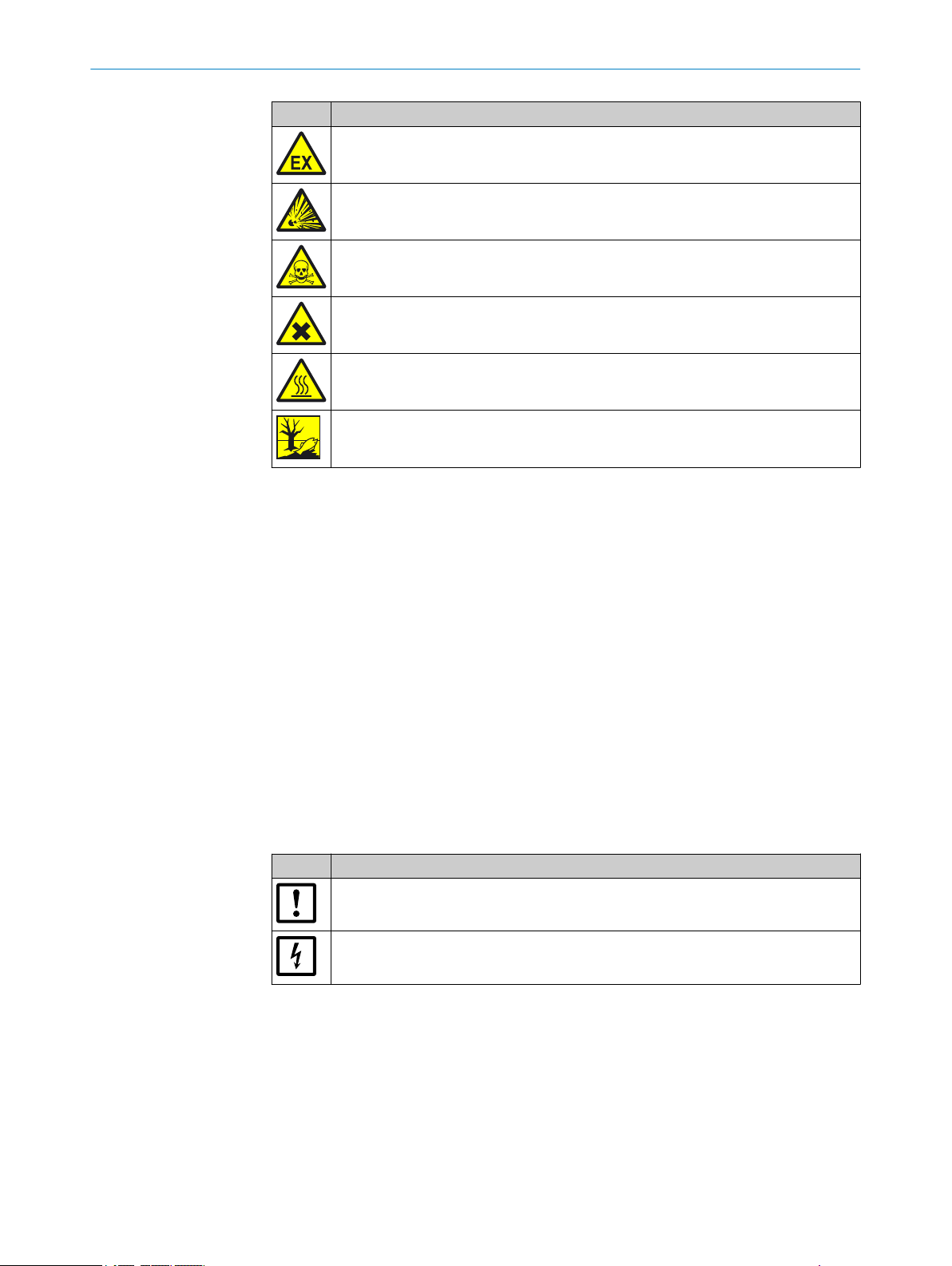
Symbol Significance
Hazard in potentially explosive atmospheres
Hazard by explosive substances/mixtures
Hazard by toxic substances
Hazards by noxious substances
Hazard by high temperature
Hazard for the environment/nature/organic life
1.4.2 Warning levels / Signal words
ABOUT THIS DOCUMENT 1
DANGER
Risk or hazardous situation which will result in severe personal injury or death.
WARNING
Risk or hazardous situation which could result in severe personal injury or death.
CAUTION
Hazard or unsafe practice which could result in less severe or minor injuries.
Notice
Hazard which could result in property damage.
Note
Hints
1.4.3 Information symbols
Table 2: Information symbols
Symbol Significance
Important technical information for this product
Important information on electric or electronic functions
8017585/YXD9/V3-1/2017-05 | SICK T EC H NI C AL IN F OR M AT I ON | MARSIC300
Subject to change without notice
7
Page 8
2 INSTALLATION
2 Installation
2.1 Gas supply terminology
Definition of utility gases:
Zero gas: Gas to adjust the zero point. Instrument air or nitrogen (N2)
•
Span gas: Gas to adjust the upper measuring range value
•
Test gas: Generic term for zero and span gas
•
Instrument air: Clean compressed air
•
Gas quality: see "Supply gases", page 87.
2.2 Installation information
2.2.1 Information on power supply
The operator is responsible for correct laying and connection of the electric lines.
WARNING
Danger to life by electric voltage
Only allow an authorized electrician to work on the electric system
b
ATTENTION
The analyzer power supply is configured for an individual power system
Check the configured power system against the system documentation provided.
If the analyzer power system does not match the power system on board: Please
b
contact SICK Customer Service.
When selecting and laying the electric lines for power supply, observe the applicable
local standards and guidelines.
2.2.2 Notes on the gas supply
The operator is responsible for the correct laying of the sample gas lines.
ATTENTION
Risk of contamination of the analyzer by unclean instrument air.
Only use instrument air corresponding to the mandatory specification (see "Techni‐
b
cal data", page 78).
Install a suitable instrument air conditioning when necessary.
b
8
T EC H NI C AL IN F OR M AT I ON | MARSIC300 8017585/YXD9/V3-1/2017-05 | SICK
Subject to change without notice
Page 9
2.2.3 Tube screw fitting
1
Swagelok screw fitting
Figure 1: Swagelok screw fitting
INSTALLATION 2
Push the tube up to the stop in the
b
tube screw fitting.
Turn the cap nut finger-tight.
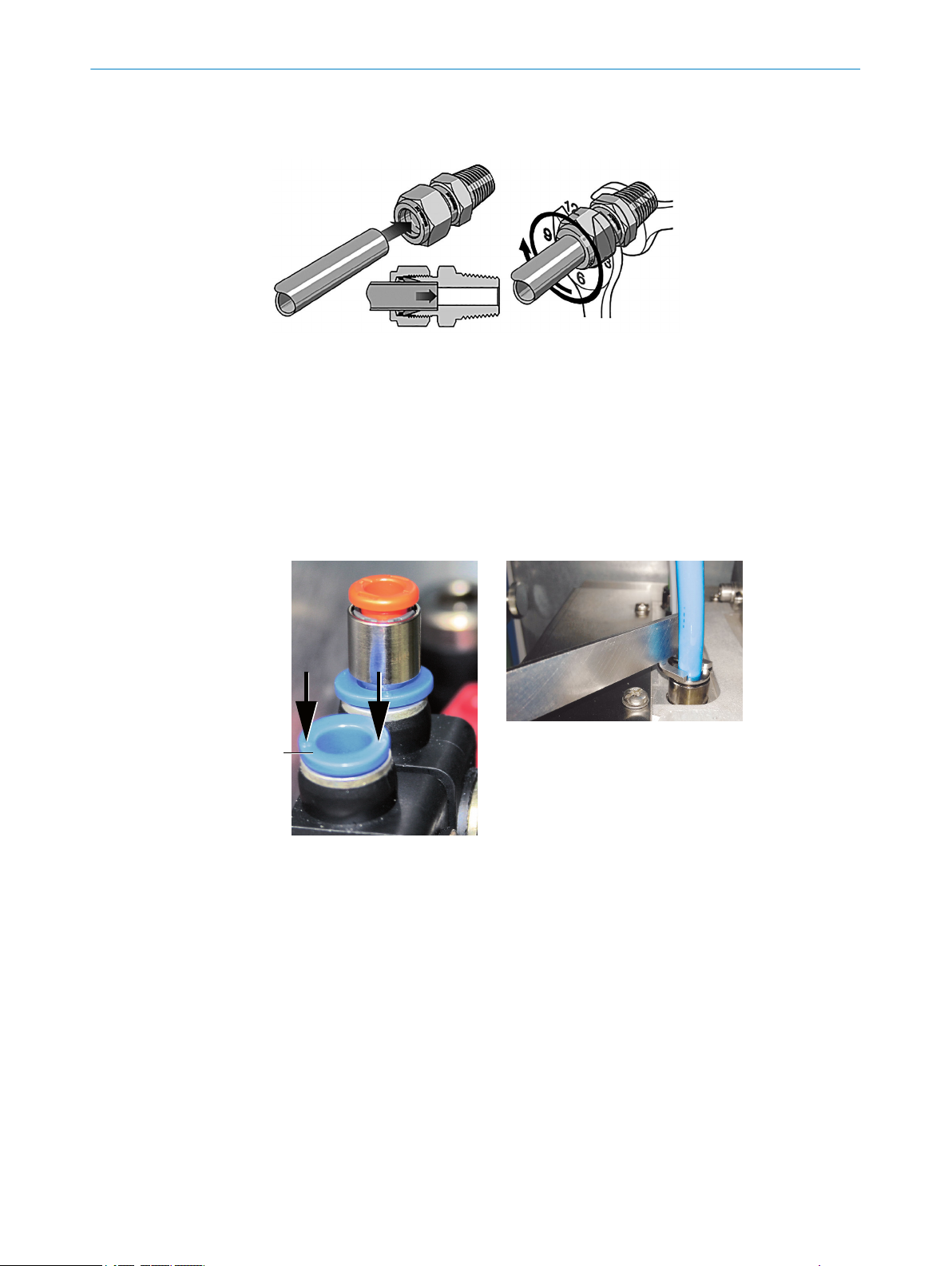
Push-in fitting (pneumatic)
Figure 2: Push-in fitting with
retaining ring
Retaining ring
1
During initial assembly: Hold the fitting
b
bolt steady and tighten the cap nut
with 1 1/4 revolutions.
During refitting: Tighten the cap nut to
b
the previous position (the resistance
increases noticeably) and then slightly
tighten.
Figure 3: Using the pressure tool
Pressure tool
Connecting the tube: Push tube in.
b
Disconnecting the tube: Press the retaining ring in and pull the tube out.
b
It is easier to press the retaining ring in using the pressure tool provided.
2.3 Scope of delivery
Please see the delivery documents for the scope of delivery.
2.4 Provision by operator
To be provided by operator, especially:
Suitable flange on the exhaust duct (see “Operating Instructions SFU”)
•
Fixing accessories of enclosures (dowels, screws, etc.)
•
8017585/YXD9/V3-1/2017-05 | SICK T EC H NI C AL IN F OR M AT I ON | MARSIC300
Subject to change without notice
9
Page 10
1
2
3 3
4
5 6
7
8
1
2
1
4
2 INSTALLATION
Fixing accessories for heated sample gas line and tube bundle cable
•
Power cable: see "Power supply", page 82
•
External power disconnection unit
•
Compressed air, instrument air as zero gas when necessary
•
Observe quality of operator's instrument air: see "Supply gases", page 87
Optional span gases
•
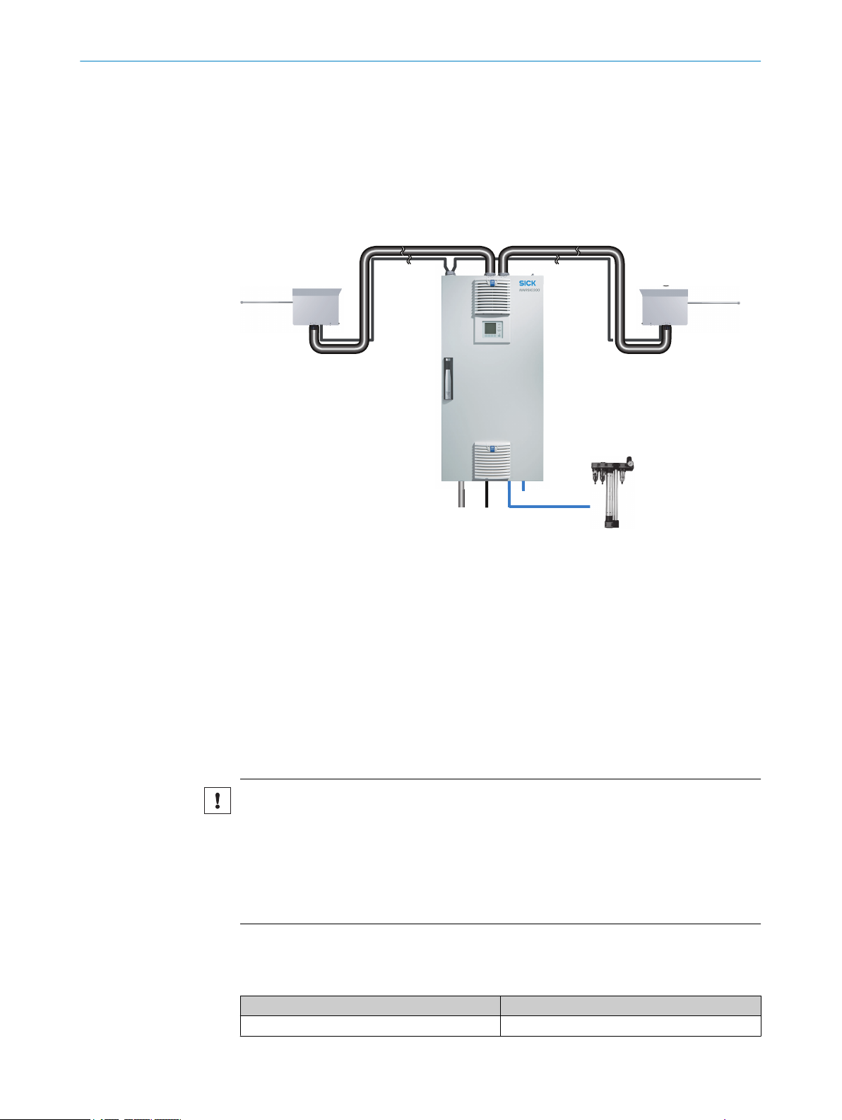
2.5 Installation overview
Figure 4: Installation - overview
Gas sampling system
1
Heated sample gas line (with 2 measuring points: 2 sample gas lines)
2
Tube bundle cable (with 2 measuring points: 2 tube bundle cables) with pneumatic and elec‐
3
tric lines
Analyzer
4
Energy supply
5
Interfaces
6
Instrument air inlet
7
Option: Instrument air conditioning
Sample gas outlet
8
2.6 Checklist for mechanical and electrical installation
NOTICE
Observe the sequence during installation. Connect the gas sampling units on the
exhaust duct as last task.
Incorrect assembly can create a risk of contaminating the gas extraction system. In this
case, exhaust gas can penetrate the unheated analyzer and possibly condensate.
1. First connect instrument air and power supply.
2. Then install the gas sampling system in the exhaust duct.
Observe laying information (Chapter see "Assembly information for sample gas lines
and tube bundle cable", page 11).
Table 3: Fitting and connecting system components
System component Reference
Install analyzer cabinet see "Installing the analyzer cabinet", page 13
10
T EC H NI C AL IN F OR M AT I ON | MARSIC300 8017585/YXD9/V3-1/2017-05 | SICK
Subject to change without notice
Page 11
System component Reference
Connect sample gas line to analyzer see "Connect the sample gas line to the analyzer",
Connect tube bundle cable to analyzer see "Connecting the tube bundle cable to the ana‐
Connect signal lines to analyzer see "Connecting the signal lines to the analyzer",
Air and gas connections on analyzer see "Air and gas connections on analyzer",
Electrical connections on analyzer see "Electrical connections on the analyzer",
Install SFU gas sampling system see "Installing the gas sampling system", page 25
Optional: Configure Modbus-Profinet /Profibus con‐
verter
Optional: Install measuring point switchover HOT‐
SAMPLER
Optional: Install MPR See Operating Instructions MPR
page 14
lyzer", page 16
page 19
page 20
page 23
see "Setting up the Modbus-Profinet converter
(optional)", page 27
See Operating Instructions HOTSAMPLER
2.7 Assembly information for sample gas lines and tube bundle cable
Installing the sample gas lines
INSTALLATION 2
WARNING
Risk of fire
Observe the laying instructions provided with the line.
b
Minimum clearance to other lines (for example, tube bundle cable): 10 cm.
b
Do not lay or roll up lines directly next to each other.
b
WARNING
Danger to life by electric voltage
Only allow an authorized electrician to work on the electric system
b
Start laying at the analyzer.
b
The end with the electric connection belongs on the analyzer.
°
Important: The screw fitting for the enclosure duct must be located at the
end of the electrical connection (analyzer side).
The end without electrical connection belongs on the gas sampling system.
°
Roll-up excess length on the gas sampling system.
Leave enough length for pulling the gas sampling system.
Protect the line from damage (chafing through vibration, mechanical load).
b
Observe minimum bend radius of 300 mm.
b
Installing the tube bundle cable
Start laying the tube bundle cable at the analyzer and roll-up excess length at the gas
sampling probe.
1. Assembly on the analyzer: see "Air and gas connections on analyzer", page 20
and see "Electrical connections on the analyzer", page 23.
2. Lay the tube bundle cable to the analyzer cabinet.
Attach excess length to the gas sampling probe.
°
Leave enough length for pulling the probe.
°
Protect the line from damage (chafing through vibration, mechanical load).
°
Minimum bend radius: 300 mm.
°
8017585/YXD9/V3-1/2017-05 | SICK T EC H NI C AL IN F OR M AT I ON | MARSIC300
Subject to change without notice
11
Page 12

≥ 100 mm
250 mm
R
≥ 30
0 mm
2 INSTALLATION
3. Assembly on the gas sampling probe: see "Installing the gas sampling system",
page 25.
NOTE
Fit the sample gas lines and tube bundle cable on the cable strips with holes.
Observe the minimum distance and bend radius.
b
Figure 5: Sample gas line - distance and radius
12
T EC H NI C AL IN F OR M AT I ON | MARSIC300 8017585/YXD9/V3-1/2017-05 | SICK
Subject to change without notice
Page 13
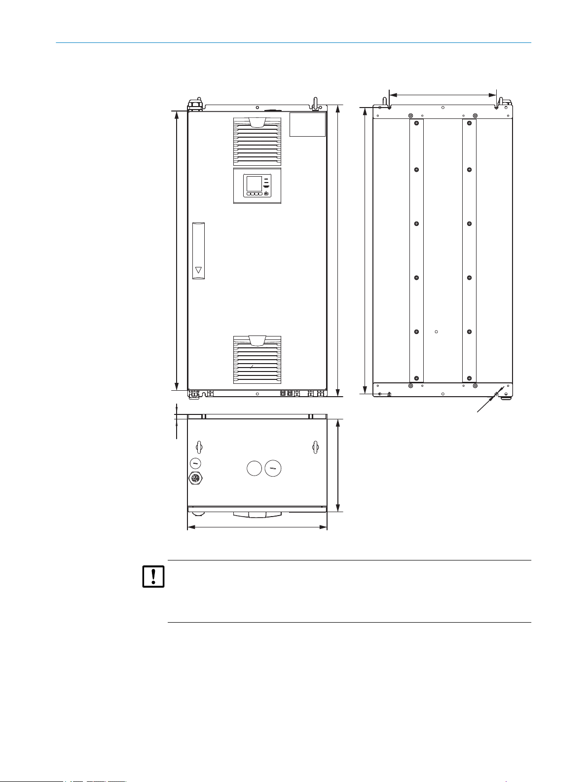
2.8 Installing the analyzer cabinet
Ø 12
1200
1254
1230
20
400
460
600
INSTALLATION 2
Figure 6: Analyzer cabinet - dimensional drawing
NOTICE
Observe clearances:
Top: 30 cm
•
Bottom: 20 cm
•
Observe the clearances for the heated sample gas line.
•
Install the analyzer in a well ventilated room at a location, when possible, with con‐
stant temperature conditions.
Observe the relevant ambient conditions: see "Ambient conditions", page 80.
•
Attach the enclosure with the mounting brackets provided on a suitable wall with
•
•
sufficient load-bearing capacity.
Secure the enclosure with 4 x M10 screw fittings (2 at bottom, 2 at top) with prop‐
•
erty class 8.8 (or higher).
8017585/YXD9/V3-1/2017-05 | SICK T EC H NI C AL IN F OR M AT I ON | MARSIC300
Subject to change without notice
13
Page 14

1
5
4
7
6
3 2
1
6
7
8
5
2
3
4
2 INSTALLATION
Secure the screw fittings against loosening.
•
Drilling plan: See dimension drawings above.
•
Install the enclosure horizontal.
•
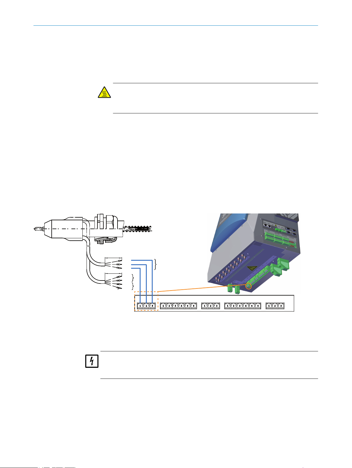
2.9 Connect the sample gas line to the analyzer
WARNING
Danger to life by electric voltage
Only allow an authorized electrician to work on the electric system
b
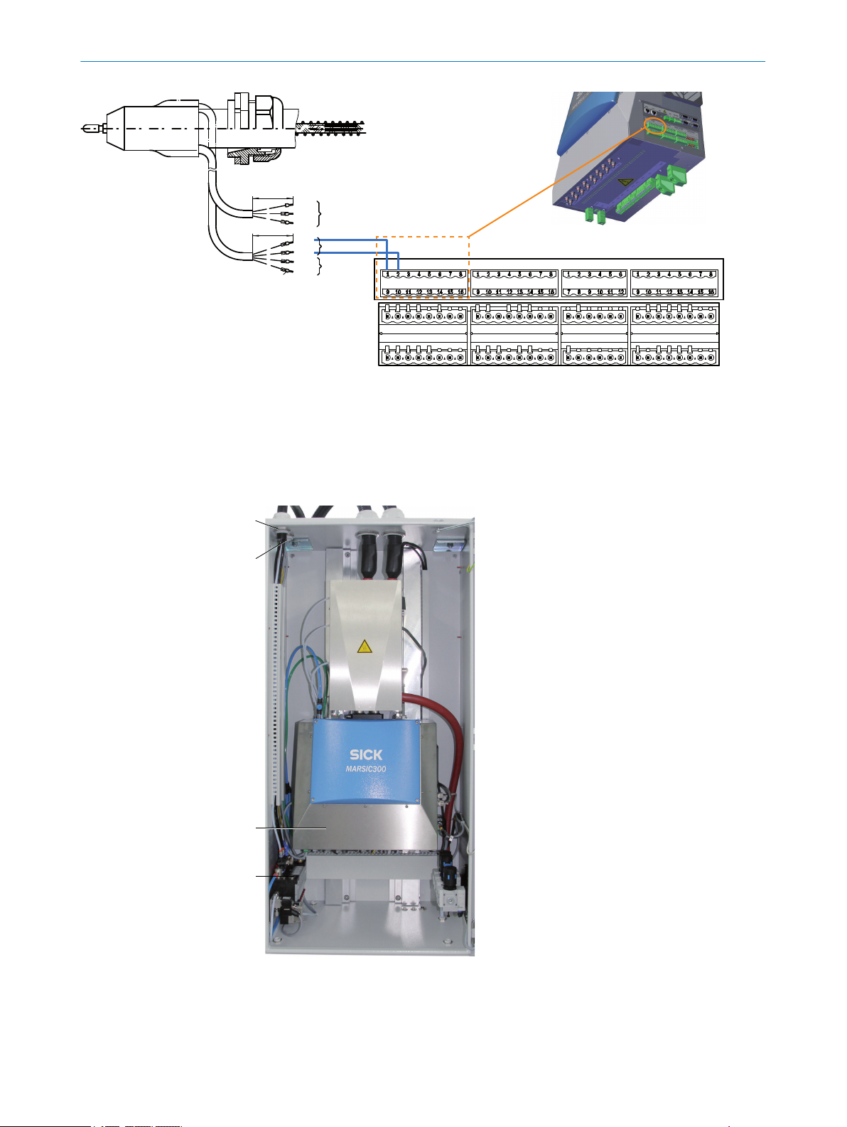
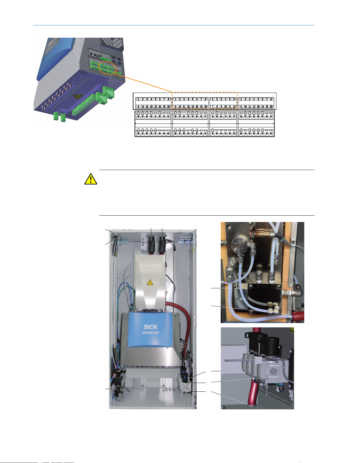
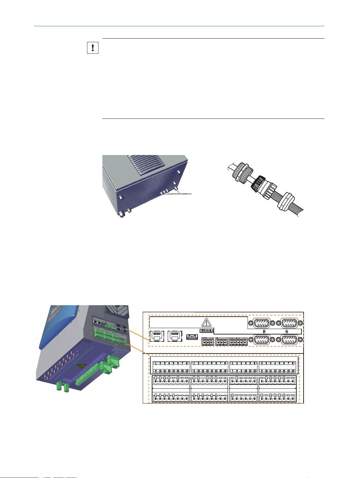
Connect heated sample gas line to analyzer
The flexible wires of the heated sample
gas line are numbered.
Line assignment: see "Heated sample
gas lines", page 81
Figure 7: Heated sample gas line
Connection side without electric connec‐
1
tions on gas sampling system
Connection side with electric connec‐
2
tions on analyzer
Protective cap
3
2 x Pt100 connections (1 as reserve)
4
Power supply
5
Cable gland
6
Counter nut
7
1. Unscrew counter nut from the cable gland and pull off the sample gas line.
2. Lead sample gas line together with electrical connections from above through the
housing opening on the analyzer.
3. Push counter nut back over the sample gas line and electric connections.
14
Figure 8: Sample gas line - connection diagram
Sample gas line 1
1
Sample gas line 2 (option)
2
Cable gland
3
Counter nut
4
Clamping ring screw connection (cell)
5
T EC H NI C AL IN F OR M AT I ON | MARSIC300 8017585/YXD9/V3-1/2017-05 | SICK
Subject to change without notice
Page 15
TUBE 1
100
100
gnge
sw 2
sw 1
sw 3
sw 4
sw 5
sw 6
PT100 I
PT100 II
Heizkreis I
FILTER 1 PROBE 1 FILTER 2 PROBE 2TUBE 2 TUBE 3
INSTALLATION 2
Cable duct
6
Foam insulation
7
Finished assembly
8
4. Screw counter nut tight on the cable gland.
5. Unscrew cell cover and remove.
CAUTION
Hot parts in cell.
Let cell cool down before working on the cell.
b
6. Remove protective cap from sample gas line.
7. Insert sample gas line to stop in the clamping ring screw connection on the cell.
With 2 sample gas lines: Observe inlets:
Right inlet: Measuring point 1
°
Left inlet: Measuring point 2
°
8. Screw sample gas line tight on the clamping ring screw connection.
9. Attach red foam insulation on the clamping ring screw connection and bind
together with a cable clip. No thermal bridges may remain.
10. Close cell again.
11. Screw cable gland tight.
12. Push electric lines downwards through the cable duct.
13. Connect power supply of the sample gas line:
Figure 9: Power supply connection
Complete description of the interface on page 82.
Connect the optional second sample gas line (TUBE 2).
b
NOTICE
The connections on MARSIC300 must match the connections of the gas sampling sys‐
tem.
14. Connect Pt100 of the sample gas line:
8017585/YXD9/V3-1/2017-05 | SICK T EC H NI C AL IN F OR M AT I ON | MARSIC300
Subject to change without notice
15
Page 16
PT100 DIGITAL INPUTS DIGITAL OUTPUTS VALVE OUTPUTS
100
100
gnge
sw 2
sw 1
sw 3
sw 4
sw 5
sw 6
PT100 I
PT100 II
Heizkreis I
1
2
3
4
2 INSTALLATION
Figure 10: Pt100 connection
Complete description of the interface on page 86.
15. Connect Pt100 from the sample gas line 2 to pins 9 and 10.
2.10 Connecting the tube bundle cable to the analyzer
16
Figure 11: Analyzer - overview
T EC H NI C AL IN F OR M AT I ON | MARSIC300 8017585/YXD9/V3-1/2017-05 | SICK
Tube bundle cable 1
1
Tube bundle cable 2 (optional)
2
3
4
Valve block
Electronics unit
Subject to change without notice
Page 17
1
4
2
3
6
5
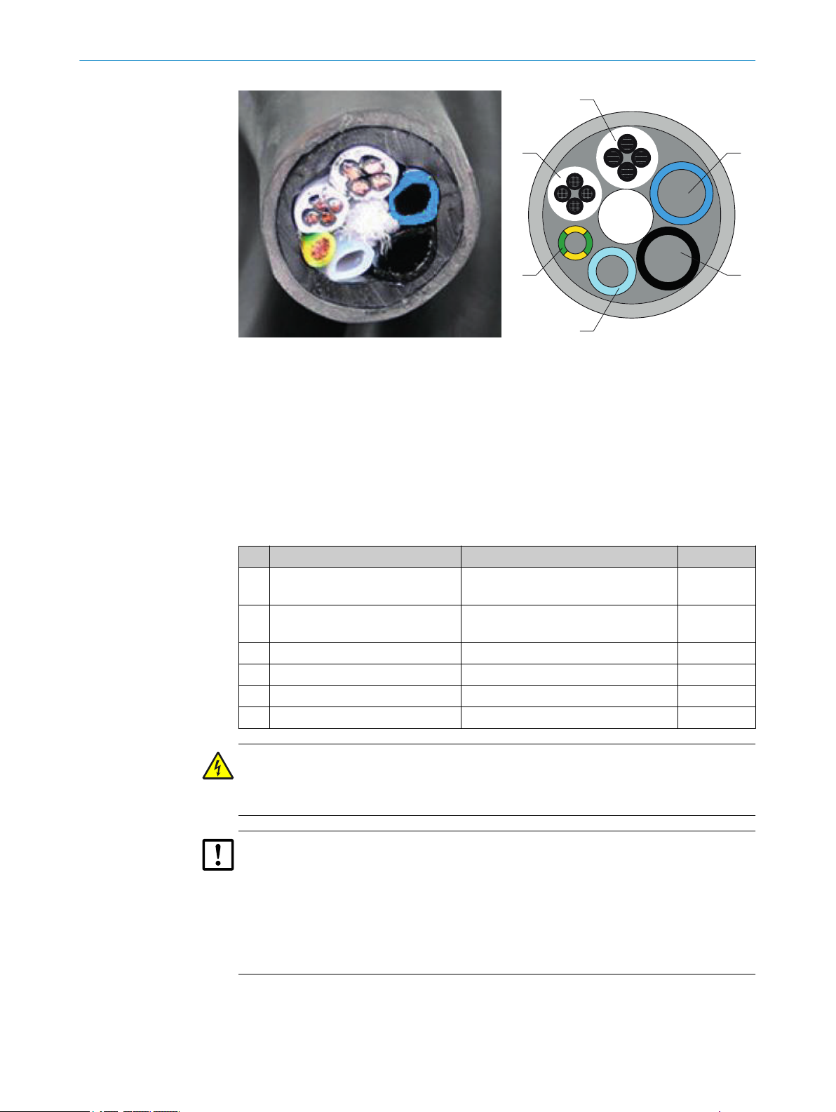
Figure 12: Tube bundle cable - overview
Power supply
1
Pt100 lines
2
Grounding conductor
3
PTFE tube DN4/6
4
PA tube black DN6/8; Imprint “1”
5
Connections on analyzer and gas sampling probe must match
PA tube black DN6/8; Imprint “2”
6
Connections on analyzer and gas sampling probe must match
INSTALLATION 2
No. Designation Function Dimension
Power supplies Lines 1 and 2: Gas sampling filter
1
Lines 3 and 4: Probe tube (optional)
Signal lines (Pt100) Lines 1 and 2: Gas sampling filter
2
Lines 3 and 4: Probe tube (optional)
Grounding conductor (gnge) Ground 1 x 4.0 mm
3
PTFE hose (white) Zero gas DN 4/6
4
PA hose (black) Control air main valve DN 6/8
5
PA hose (blue) Backflush air DN 6/8
6
4 x 1.5 mm
4 x 1.0 mm
WARNING
Danger to life by electric voltage
Only allow an authorized electrician to work on the electric system
b
CAUTION
The tube bundle cable is unusable when it is cut off too short.
The tube bundle cable is unusable when a lead inside is damaged when removing the
sheath.
If the tube bundle cable is long enough: Leave a piece as “reserve”.
b
Only remove the sheath from the tube bundle cable when you are technically capa‐
b
ble of doing this.
2
2
2
1. Remove 1900 mm of the tube bundle cable sheath.
2. Lead the tube bundle cable through the screw fitting on the enclosure top.
3. Lead tubes and lines of the tube bundle cable downwards in the cable duct.
8017585/YXD9/V3-1/2017-05 | SICK T EC H NI C AL IN F OR M AT I ON | MARSIC300
Subject to change without notice
17
Page 18
1 2 3 4 5 67
8
9
1
4
2
3
6
5
TUBE 1 FILTER 1 PROBE 1 FILTER 2 PROBE 2TUBE 2 TUBE 3
!
$
§
"
gnge
2 INSTALLATION
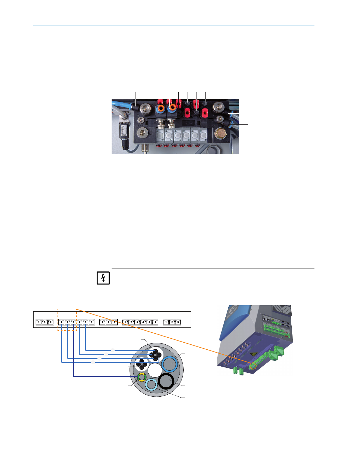
4. Connect the 3 gas lines of one tube bundle cable to the valve block (connections
marked as “outlet” in the Figure below).
NOTICE
The gas connections on the valve block must match the gas connections of the
gas sampling system (see "SFU Gas Sampling System Operating Instructions").
Figure 13: Valve block
Outlet: Zero gas measuring point 1
1
Outlet: Zero gas measuring point 2 (option)
2
Outlet: Control air measuring point 1
3
Outlet: Backflush air measuring point 1
4
Outlet: Control air measuring point 2 (option)
5
Outlet: Backflush air measuring point 2 (option)
6
Inlet: Zero gas
7
Inlet: Control/backflush air
8
Inlet: Auxiliary control air
9
Red plug = dummy plug
-
5. Connect the heating of the gas sampling system (heated sample gas filter and
optional heated probe tube).
NOTICE
The connections on MARSIC300 must match the connections of the gas sampling
system.
Figure 14: Supply lines - tube bundle cable connection diagram
Complete description of the interface, see "Tube bundle cable", page 81 Tube bundle
cable 2 optional to tube bundle cable 1.
18
T EC H NI C AL IN F OR M AT I ON | MARSIC300 8017585/YXD9/V3-1/2017-05 | SICK
Subject to change without notice
Page 19
1
4
2
3
6
5
PT100 DIGITAL INPUTS DIGITAL OUTPUTS VALVE OUTPUTS
!
$
§
"
INSTALLATION 2
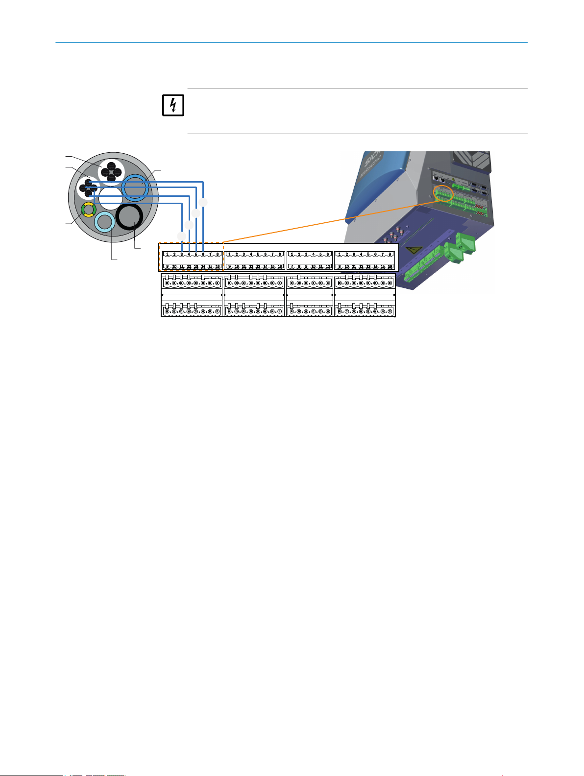
6. Connect the Pt100 of the gas sampling system (heated sample gas filter and
optional heated probe tube).
NOTICE
The connections on MARSIC300 must match the connections of the gas sampling
system.
Figure 15: Signal lines - tube bundle cable connection diagram
2.11 Connecting the signal lines to the analyzer
4 digital inputs and outputs each are available as an option that must then be config‐
ured, see "Data interfaces / IO", page 55.
4 digital inputs
Fill level signal, condensate container
•
Condition, instrument air
•
Scrubber system on/off (can be linked with StBy MARSIC300)
•
Temperature error, weatherproof cover or other external alarm
•
4 digital outputs
Status (OK / Maintenance)
•
Status (OK / Failure)
•
Coefficient SO2/CO2 less than/greater than xy (definable)
•
The inputs and outputs are deactivated as standard. The inputs and outputs can be
activated and negated in SOPAS ET.
Digital inputs and outputs can also be redefined differently to the above description.
8017585/YXD9/V3-1/2017-05 | SICK T EC H NI C AL IN F OR M AT I ON | MARSIC300
Subject to change without notice
19
Page 20
PT100 DIGITAL INPUTS DIGITAL OUTPUTS VALVE OUTPUTS
3
12
4
7
5
6
8
9
ß
2 INSTALLATION
Figure 16: Connection diagram - digital connections
2.12 Air and gas connections on analyzer
WARNING
Hazard when pressure is too high
Hoses can burst when the pressure is too high.
Observe the maximum pressures of the gases provided by the operator: see "Sup‐
b
ply gases", page 87.
20
Figure 17: Overview - air and gas connections
Heated sample gas line for measuring point 1
1
Heated sample gas line for measuring point 2 (option)
2
T EC H NI C AL IN F OR M AT I ON | MARSIC300 8017585/YXD9/V3-1/2017-05 | SICK
Subject to change without notice
Page 21
INSTALLATION
Tube bundle cable 1
3
Tube bundle cable 2 (option)
4
Pressure reducer unit
5
Instrument air as zero gas/test gas (option)
6
Test gas inlet
7
Sample gas outlet
8
Sample gas outlet on cell
9
Fixing of line sample gas outlet on the cell
ß
Connect instrument air
Connect instrument air to the pressure control unit.
ATTENTION
Risk of contamination of the analyzer by unclean instrument air.
Only use instrument air corresponding to the mandatory specification (see "Techni‐
b
cal data", page 78).
Install a suitable instrument air conditioning when necessary.
b
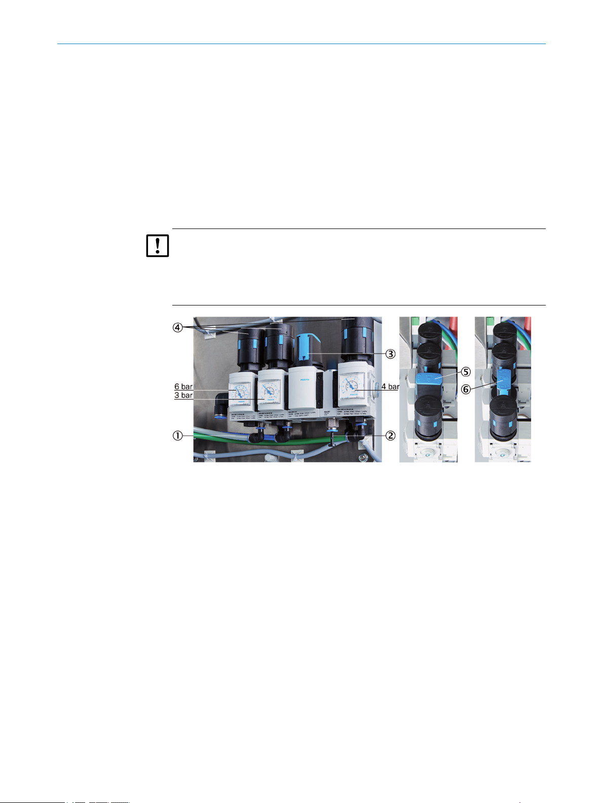
2
Figure 18: Pressure reducer unit
Instrument air inlet with zero gas quality
1
Instrument air inlet for induction air ejector only
2
Manual valve for instrument air selection
3
3 pressure reducers (adjustable)
4
Manual valve - closed position
5
Manual valve - open position
6
The instrument air is used as both induction air for the ejector (cell) and zero/control
air.
Instrument air can be connected in 2 ways:
One common instrument air supply for ejector air and zero/control air (inlet 1).
b
Separate instrument air supply for:
b
Ejector air (inlet 2)
°
and zero/control air (inlet 1)
°
Instrument air quality
The requirements for instrument air quality are lower when the air is only used as
ejector air than when used as zero/control air (zero gas quality) (see "Supply
gases", page 87).
When connected just as instrument air supply with zero gas quality to be used as
b
common air for both ejector air and zero/control air (on inlet 1):
8017585/YXD9/V3-1/2017-05 | SICK T EC H NI C AL IN F OR M AT I ON | MARSIC300
Subject to change without notice
21
Page 22
1
2
2 INSTALLATION
Set manual valve to position “open”.
w
When connected as one instrument air supply for the ejector (on inlet 2) and one
b
instrument air supply with zero gas quality (on inlet 1):
Set manual valve to position “closed”.
w
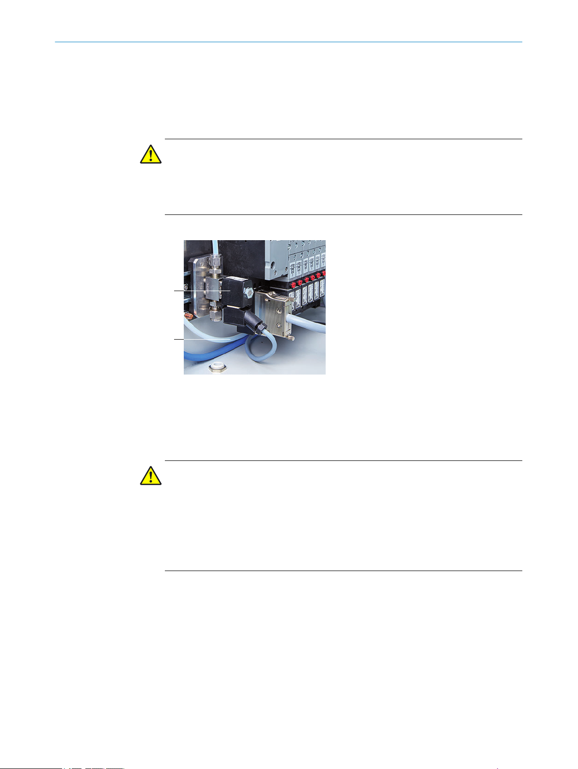
Connect span gas (option)
WARNING
Hazard when pressure is too high
Hoses can burst when the pressure is too high.
Observe the maximum pressures of the gases provided by the operator: see "Sup‐
b
ply gases", page 87.
Connect span gas to the span gas valve.
Figure 19: Test gas valve connection
Test gas valve
1
Test gas inlet
2
Connect sample gas outlet
CAUTION
Acidic condensate in sample gas outlet - risk of blockage
Acidic condensate forms in the sample gas outlet.
Always lay the sample gas outlet line running downwards so that no condensate
b
can accumulate.
Lay the line end in a suitable disposal device (drain or condensate collection con‐
b
tainer).
Do not kink the line and protect against frost.
b
The analyzer is fitted with an outlet hose (DIN 8/10) about 30 cm long when delivered.
Lay the sample gas outlet in a suitable exhaust duct.
•
The sample gas outlet must be open to the ambient pressure.
•
Recommendation for lengthening the outlet hose:
To prevent the outlet line clogging, it is recommended to lay a (1) new line starting at
the sample gas outlet of the cell to the disposal location.
22
To do this, see figure 17, page 20:
1. Open cell cover (loosen 4 screws on the side).
2. Unscrew sample gas outlet line on the sample gas outlet (bracket piece).
3. Loosen fixing of sample gas outlet line.
T EC H NI C AL IN F OR M AT I ON | MARSIC300 8017585/YXD9/V3-1/2017-05 | SICK
Subject to change without notice
Page 23
1
INSTALLATION 2
4. Remove the thermal insulation from the existing line and remove the line.
5. Lead a new line through the enclosure duct at the bottom on the enclosure floor
and connect it to the sample gas outlet of the cell.
6. Refit the fixing.
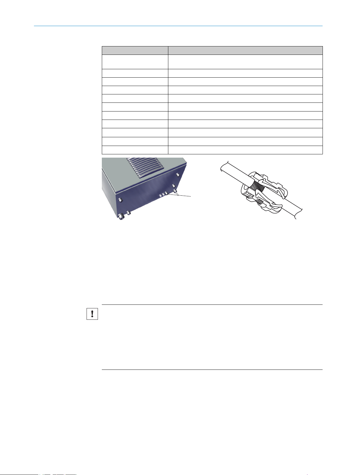
7. Refit the thermal insulation.
8. Close cell again.
To lengthen the existing hose piece: No cross-section narrowing may occur when con‐
necting the lengthening hose.
Sample gas outlet on housing:
Figure 20: Sample gas outlet - enclosure under‐
side
Sample gas outlet at bottom rear of the
1
housing
2.13 Electrical connections on the analyzer
Connect power supply
ATTENTION
The analyzer power supply is configured for an individual power system
Check the configured power system against the system documentation provided.
If the analyzer power system does not match the power system on board: Please
b
contact SICK Customer Service.
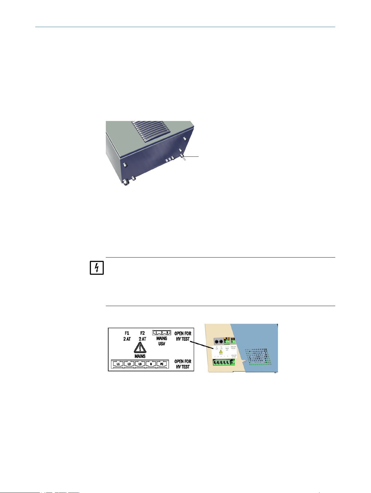
The power supply is located on the left on the analyzer.
Figure 21: Power supply connections
8017585/YXD9/V3-1/2017-05 | SICK T EC H NI C AL IN F OR M AT I ON | MARSIC300
Subject to change without notice
23
Page 24
1
ETHO E TH1 USB CAN PROFIBUS
1 2 RS422/RS485 RS232 02 DISP.
PT100 DIGITAL INPUTS DIGITAL OUTPUTS VALVE OUTPUTS
I/0-MOD.
2 INSTALLATION
NOTICE
Install an external power disconnection unit which disconnects all connectors
°
and fuses near the analyzer.
The power disconnection unit must be marked clearly and be easily accessi‐
°
ble.
Observe the maximum power input of the complete system: see "Power sup‐
ply", page 82.
The onsite wiring system to the power source of the system must be installed
°
and fused according to the relevant regulations.
Always connect a protective ground to PE.
°
Route the electric lines through the screw fittings of the enclosure.
b
Connect the electric lines.
b
Connect signal line (optional)
1
b
b
Connect Ethernet (optional)
Figure 22: Connections overview
2 x signal line ducts
Lead cable through the enclosure duct.
Attach shield as shown in the Figure above.
24
T EC H NI C AL IN F OR M AT I ON | MARSIC300 8017585/YXD9/V3-1/2017-05 | SICK
Subject to change without notice
Page 25
1
INSTALLATION 2
Table 4: Data interfaces - overview
Plug Connection for
ETH0 Ethernet (e.g. SOPAS ET), MPR (remote maintenance), communication via
ETH1 Internal
USB Internal
SD card SD card (on the right, next to USB)
CAN1 Internal
CAN2 Internal
RS422, RS485 Internal
RS232 (top plug) Internal
O2 (bottom plug) O2 sensor
DISP (top plug) Display
I/O-MOD (bottom plug) Internal
Modbus TCP
Ethernet cable duct
1
Lead cable through the enclosure duct.
b
Attach shield as shown in the corresponding Figure above.
b
Connect Ethernet to ETH0 (network or computer with SOPAS ET).
b
Plug type: RJ 45.
Connect MPR (remote maintenance via SICK Meeting-Point Router) to ETH0.
b
Further information, see “MPR Operating Instructions”.
2.14 Installing the gas sampling system
NOTICE
Observe the ambient conditions of the gas sampling system: See “SFU Gas Sam‐
b
pling System Operating Instructions”.
Leave the sample gas line and tube bundle cable long enough to be able to pull
b
the sample gas system out of the exhaust duct.
All connections must match the connections in the analyzer (see "Connecting the
b
tube bundle cable to the analyzer", page 16 and see "Connect the sample gas line
to the analyzer", page 14).
Fitting the flange
Install the flange of the gas sampling system as described in the “SFU Gas Sam‐
b
pling System Operating Instructions”.
Observe the 10° tilt of the probe tube during installation.
°
8017585/YXD9/V3-1/2017-05 | SICK T EC H NI C AL IN F OR M AT I ON | MARSIC300
Subject to change without notice
25
Page 26
min.70
10°
~
~30
1
2
3 4
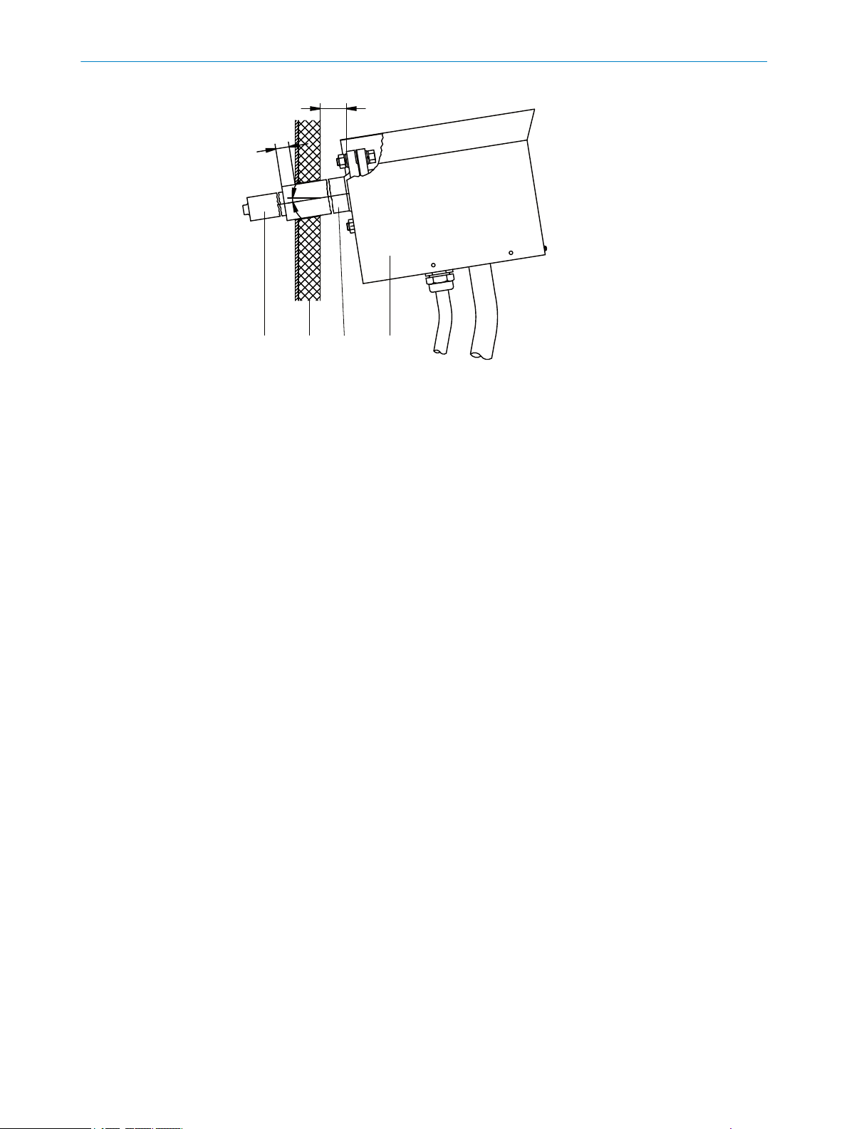
2 INSTALLATION
Figure 23: Flange assembly
Probe tube
1
Stack wall
2
Welding neck flange
3
Gas sampling filter
4
Gas connections
Connect the following gas connections on the gas sampling system:
b
Heated sample gas line
°
Tube bundle cable
°
Electrical connections
Connect the following electric lines of the tube bundle cable on the gas sampling
b
system:
°
°
°
°
Black line 1: Main valve
•
Blue line 2: Backflush
•
White PTFE tube: Instrument air/test gas
•
Power supply, gas sampling system
Power supply, probe tube (when heated)
Filter Pt100 line
Pt100 line, probe tube (optional, when heated)
26
T EC H NI C AL IN F OR M AT I ON | MARSIC300 8017585/YXD9/V3-1/2017-05 | SICK
Subject to change without notice
Page 27
Tube bundle cable
1
4
2
3
6
5
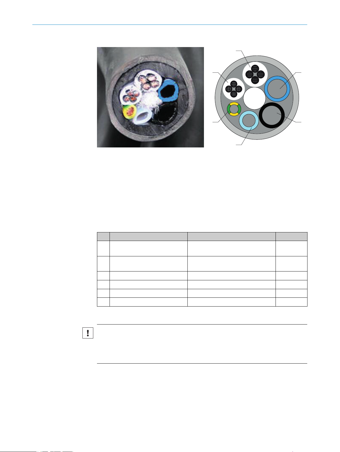
Figure 24: Tube bundle cable - overview
Power supply
1
Pt100 lines
2
Grounding conductor
3
PTFE tube DN4/6
4
PA tube black DN6/8; Imprint “1”
5
Connections on analyzer and gas sampling probe must match
PA tube black DN6/8; Imprint “2”
6
Connections on analyzer and gas sampling probe must match
INSTALLATION 2
2.15
No. Name Function Dimension
Power supplies Lines 1 and 2: Gas sampling filter
1
Lines 3 and 4: Probe tube (optional)
Signal lines (Pt100) Lines 1 and 2: Gas sampling filter
2
Lines 3 and 4: Probe tube (optional)
Grounding conductor (gnge) Ground 1 x 4.0 mm
3
PTFE hose (white) Zero gas DN 4/6
4
PA hose (black) Control air, main valve DN 6/8
5
PA hose (blue) Backflush air DN 6/8
6
Fit the gas sampling system on the flange
NOTICE
Risk of contamination of gas sampling system
First install the gas sampling system on the exhaust duct just before the analyzer
b
is switched on.
Install the gas sampling system: See “SFU Gas Sampling System Operating
b
Instructions”.
Setting up the Modbus-Profinet converter (optional)
4 x 1.5 mm
4 x 1.0 mm
2
2
2
As an option to Modbus, the MARSIC300 can also be configured with a Profinet or Profi‐
bus protocol. This requires an external Modbus-Profinet converter that may require
some adjustments.
8017585/YXD9/V3-1/2017-05 | SICK T EC H NI C AL IN F OR M AT I ON | MARSIC300
Subject to change without notice
27
Page 28
INSTALLATION
2
Configuration:
1. Install the converter onsite on a DIN rail and create a connection to the MAR‐
SIC300 (Modbus-TCP).
2. Connect the converter to 24 V DC.
3. Connect a PC via one of the Modbus-TCP connections of the converter with a net‐
work cable (crossover not required).
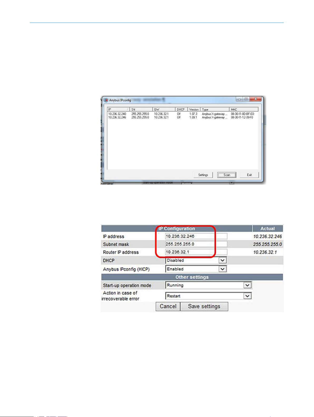
Use the “IP config” software on the Product-CD to find the IP address of the con‐
verter in the network using its MAC address (the MAC address is on a label on the
converter (next to the TCP interface).
Figure 25: Menu window Anybus IPconfig
4. Start a web browser (IE7.0 or 8.0), enter the IP address and a connection to xGateway to the web interface.
5. Define your specific IP address incl. subnet of the converter that matches your net‐
work and safety settings.
Figure 26: Menu Configuration/Modbus Client
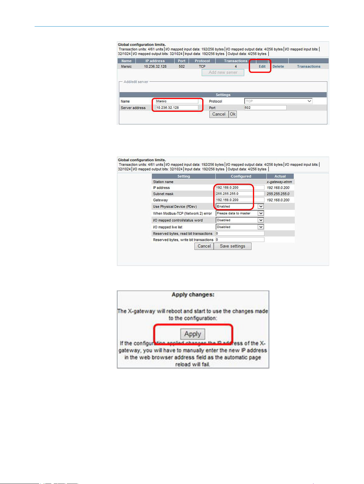
6. Enter the name, IP address and port of the MARSIC300.
28
T EC H NI C AL IN F OR M AT I ON | MARSIC300 8017585/YXD9/V3-1/2017-05 | SICK
Subject to change without notice
Page 29
INSTALLATION
Figure 27: Menu Configuration/Modbus Servers
7. Enter address from PROFINET and save the settings. The address must be the
same as in the operator-side SPS.
2
Figure 28: Menu Configuration/PROFINET IO
8. Click “Apply” to activate all changes.
Figure 29: Menu Tools/X-gateway management
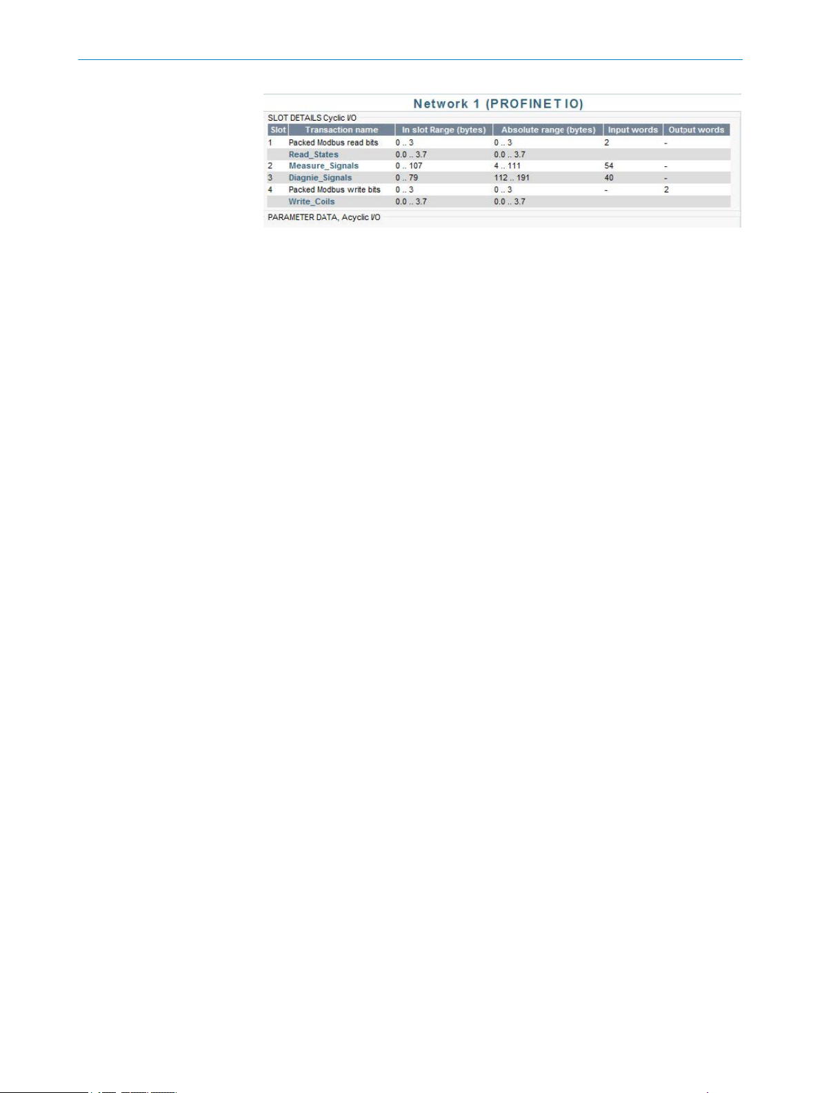
9. Setup the hardware configuration on the operator-side (operator SPS) according to
the following Table:
8017585/YXD9/V3-1/2017-05 | SICK T EC H NI C AL IN F OR M AT I ON | MARSIC300
Subject to change without notice
29
Page 30
2 INSTALLATION
Figure 30: Byte sequence
10. Set the byte sequence. The byte sequence can be set in MARSIC300 when
desired.
A connection to the PC with SOPAS ET is then necessary.
30
T EC H NI C AL IN F OR M AT I ON | MARSIC300 8017585/YXD9/V3-1/2017-05 | SICK
Subject to change without notice
Page 31

INSTALLATION 2
Figure 31: Menu Tree Parameters/Modbus in SOPAS ET
Set the register swap in SOPAS ET to CD_AB for Siemens controls.
8017585/YXD9/V3-1/2017-05 | SICK T EC H NI C AL IN F OR M AT I ON | MARSIC300
Subject to change without notice
31
Page 32

INSTALLATION
2
Figure 32: Menu Modbus in SOPAS ET
2.16 Setting up the Modbus-Profinet converter (optional)
As an option to Modbus, the MARSIC300 can also be configured with a Profinet or Profi‐
bus protocol. This requires an external Modbus-Profibus converter that may have to be
adjusted.
How to configure the external converter is described in the following:
1. Install the converter onsite on a DIN rail and create a connection to the MAR‐
SIC300 (Modbus-TCP).
2. Connect the converter to 24 V DC.
3. Connect a PC via one of the Modbus-TCP connections of the converter with a net‐
work cable (crossover not required).
Use the “IP config” software on the Product-CD to find the IP address of the con‐
verter in the network using its MAC address (the MAC address is on a label on the
converter (next to the TCP interface).
32
Figure 33: Menu window Anybus IPconfig
4. Start a web browser (IE7.0 or 8.0), enter the IP address and a connection to xGateway to the web interface.
5. Define your specific IP address incl. subnet of the converter that matches your net‐
work and safety settings.
T EC H NI C AL IN F OR M AT I ON | MARSIC300 8017585/YXD9/V3-1/2017-05 | SICK
Subject to change without notice
Page 33

Figure 34: Menu Configuration/Modbus Client
6. Enter the name, IP address and port of the MARSIC300.
INSTALLATION
2
Figure 35: Menu Configuration/Modbus Servers
7. Enter the address of PROFIBUS and save the settings. The address must be the
same as in the operator-side SPS.
Figure 36: Menu Configuration/PROFIBUS DP-V1
8. Click “Apply” to activate all changes.
8017585/YXD9/V3-1/2017-05 | SICK T EC H NI C AL IN F OR M AT I ON | MARSIC300
Subject to change without notice
33
Page 34

2 INSTALLATION
Figure 37: Menu Tools/X-gateway management
9. Setup the hardware configuration on the operator-side (operator SPS) according to
the following Table:
Figure 38: Byte sequence
10. Set the byte sequence. The byte sequence can be set in MARSIC300 when
desired.
A connection to the PC with SOPAS ET is then necessary.
34
T EC H NI C AL IN F OR M AT I ON | MARSIC300 8017585/YXD9/V3-1/2017-05 | SICK
Subject to change without notice
Page 35

INSTALLATION 2
Figure 39: Menu Tree Parameters/Modbus in SOPAS ET
Set the register swap in SOPAS ET to CD_AB for Siemens controls.
8017585/YXD9/V3-1/2017-05 | SICK T EC H NI C AL IN F OR M AT I ON | MARSIC300
Subject to change without notice
35
Page 36

2 INSTALLATION
Figure 40: Menu Modbus in SOPAS ET
36
T EC H NI C AL IN F OR M AT I ON | MARSIC300 8017585/YXD9/V3-1/2017-05 | SICK
Subject to change without notice
Page 37

3 Initial start-up
NOTE
Prerequisite: The system is completely installed and connected.
Before switching on
1. Check connections are connected properly as described in the “Installation” Chap‐
2. Relieve the pressure on all pressure regulators in the analyzer (see "Air and gas
3. Adjust the manual valve in the analyzer as described in see "Air and gas connec‐
4. Open the external instrument air supply.
5. Set pressures: see "Air and gas connections on analyzer", page 20.
6. Check the power supply of the analyzer matches the setting on the ship network:
7. Check the voltage connection on the gas sampling system.
8. Install the gas sampling system on the flange of the exhaust duct: See “SFU Gas
INITIAL START-UP 3
ters.
connections on analyzer", page 20): Turn the regulators counterclockwise.
tions on analyzer", page 20 .
see "Electrical connections on the analyzer", page 23.
Sampling System Operating Instructions”.
Switching on
1. Switch on the external power disconnection unit.
2. The green "Power" LED on the control panel goes on:
Energy supply is available.
3. The yellow and red LEDs go on sporadically.
4. Booting appears several times on the screen.
5. The Measuring screen appears.
6. The system heats up:
Only the green LED is on.
°
Display: Init/Heating up.
°
A downwards counter displays the maximum duration of the process.
7. Display: Conditioning.
8. Only the green LED is on and Measuring is shown in the status line.
The system is ready for operation.
If a measured values blinks: The measured value is outside the calibration range.
When the yellow or red LED is on: Press the Diag button and clear the error: Error
list see "Error messages and possible causes", page 93.
Final tests and parameter settings
1. Perform a leak tightness check: see "Leak tightness check during initial startup",
page 75.
2. Perform an internal adjustment: Display menu Adjustment/internal adjustment.
3. Connect computer with SOPAS ET on ETH0 (see "Connections in analyzer",
page 83) (see "Software SOPAS ET", page 39).
If the customer network is already connected: Disconnect the customer network.
4. If required: Set the times for automatic adjustments.
To change in SOPAS ET: Menu Adjustment/Parameter/Start times.
w
5. If required: Configure the measuring point switchover.
In SOPAS ET: Menu Parameterization/Sequence Controls/Sampling point pro‐
w
gram.
6. Set the IP address of the customer network for the ETH0.
°
In the SOPAS ET user interface: Click the pen symbol in the device tile of the
MARSIC300.
8017585/YXD9/V3-1/2017-05 | SICK T EC H NI C AL IN F OR M AT I ON | MARSIC300
Subject to change without notice
37
Page 38

3 INITIAL START-UP
Figure 41: SOPAS ET device
tile
7. Disconnect the computer from ETH0 and connect the customer network to ETH0.
Initial start-up is completed.
38
T EC H NI C AL IN F OR M AT I ON | MARSIC300 8017585/YXD9/V3-1/2017-05 | SICK
Subject to change without notice
Page 39

4 Configuration software
4.1 Software SOPAS ET
SOPAS ET can also be used to the configure MARSIC300 and to access the MAR‐
SIC300 logbook.
SOPAS ET runs on an external PC connected to the MARSIC300 via the Ethernet inter‐
face.
Connect MARSIC300 with software SOPAS ET
1. Make sure all electric and pneumatic connections are connected properly, start-up
has been carried out correctly and the system is running without error messages.
Connect your computer with SICK software SOPAS ET installed (on the Product CD
or free in internet under www.sick.com):
CONFIGURATION SOFTWARE
4
Figure 42: MARSIC300 network connection
NOTE
SOPAS ET connects automatically the first time MARSIC300 is started and
inquires whether the driver files (SDD files) for the connected device should be
downloaded. Downloading is not necessary because SOPAS ET loads the driver
files direct from the MARSIC300.
2. Start SOPAS ET on the PC and search for devices. When the MARSIC300 appears
in the right area in SOPAS ET, drag & drop it to the left Project area.
To change the IP setting of the MARSIC300, click on the pen icon (marked red in
the Figure) and confirm the message with “Yes”.
Figure 43: Menu dialog TCP/IP settings
3. If the MARSIC300 was not found, login on the MARSIC300 on the control panel as
“Authorized Operator” (password is “1234”). You can change the network settings
8017585/YXD9/V3-1/2017-05 | SICK T EC H NI C AL IN F OR M AT I ON | MARSIC300
Subject to change without notice
39
Page 40

Back Enter
Measure
1 Digital outputs
2 Digital inputs
3 Ethernet
I/O config. 3.3
/Diag/I/O
4 CONFIGURATION SOFTWARE
for the MARSIC300 here. Make sure the PC and the MARSIC300 are in the same
subnet and no firewall is active.
Set the device parameters matching your network in this menu and confirm with
“OK”. A warning appears to confirm that the device is set offline. Confirm with
“Yes”. The network configuration has been changed, however the old configuration
can still be seen. The IP configuration is updated on the operator panel and in
SOPAS ET after a restart (switching the MARSIC300 off and on).
4.2 Saving parameters
Figure 44: Menu settings IP configuration
After configuration, the MARSIC300 must be adjusted to the network settings of
the customer network.
SOPAS ET can be used to backup and restore the MARSIC300 parameters:
40
T EC H NI C AL IN F OR M AT I ON | MARSIC300 8017585/YXD9/V3-1/2017-05 | SICK
Subject to change without notice
Page 41

CONFIGURATION SOFTWARE 4
1. Click the left mouse button to select the desired device in the main window.
2. Select “Project / Project save as” to save the SOPAS ET-Project file in a local direc‐
tory on the PC.
Figure 45: Menu dialog - Save Project file
4.3 Backing up the logbook with SOPAS ET
It is useful for diagnostic purposes when the MARSIC300 logbook is made available to
Service. It can be downloaded easily and, e.g. sent per e-mail.
1. Login as “Authorized User”.
2. Select path: MARSIC300 / Diagnosis / Logbook.
3. Select “All” in the scroll down menu.
4. Select “Export” to save the log file in a local directory on the PC.
Figure 46: Menu Logbook in SOPAS ET
4.4 Passwords
There are 2 passwords:
8017585/YXD9/V3-1/2017-05 | SICK T EC H NI C AL IN F OR M AT I ON | MARSIC300
Subject to change without notice
41
Page 42

4 CONFIGURATION SOFTWARE
Table 5: Passwords
Password for Password Change password
Device display access "Authorized
User"
SOPAS ET HIDE Cannot be changed
4.5 Using the menus
Example: Menu: Parameterization/I/O/Data/External Data/Analog inputs
Figure 47: Menu Analog inputs
Table 6: Menu fields legend
Entry field Significance
1
2
3
4
5
6
1234 Changing the password: see "Instrument display",
Save current entries.
Create group
Click "Mark" and then click the desired lines.
b
To cancel "Mark": Click "Mark" again and then click an empty line.
b
In editable menus: Call up the setting menu for lines.
Click desired line. Then click "Edit".
b
Copy selected lines
Insert copied lines before a selected line
Call up "Next function group"
page 60
4.6
42
(The bottom lines in the example depend on the menu)
Menu tree (SOPAS ET)
The menu tree shown here shows the menus for user level "Authorized User".
Menu Reference
Measuring screen chapter 5.1
Measuring screens
Diagnosis chapter 7
Control values chapter 7.1
Zero drift
Span gas drift
Internal adjustment drift
Reference energy
Intensity
Sensor values chapter 7.2
Temperatures
Pressures
Flow rate
Cell
O2 sensor
Emitter
Motors
T EC H NI C AL IN F OR M AT I ON | MARSIC300 8017585/YXD9/V3-1/2017-05 | SICK
Subject to change without notice
Page 43

CONFIGURATION SOFTWARE 4
Hardware
Signals chapter 7.3
External signals
Measuring signals (MVi)
Diagnosis internal (IDOi, ID
Boolean values (BVi, LIi)
Real values (RVi)
Modbus values (MBVi)
Modbus input values (MBIVi)
Modbus input flags (MBIFi)
Modbus reference flags (MBIRi)
Filtered values (FVi)
Integer values (IVi)
Real constant (RCi)
Logbook chapter 7.4
System status chapter 7.5.1
System info chapter 7.5
Timemeter chapter 7.5
Parameter chapter 6
Measuring components chapter 6.1
Global definitions
Measuring screen chapter 6.2
Measuring Screen x
I/O chapter 6.5
Hardware plan
Data
– External data
– OPC outputs (OPCOi)
– Modbus values (MBVi)
– Modbus input values (MBIVi)
– Modbus input flags (MBIFi)
– Modbus reference flags (MBIRFi)
Sequence control programs chapter 6.4
Sampling point program (MPP)
Temperature control chapter 6.6.1
Pressure control chapter 6.6.2
Flow rate chapter 6.6.3
O2 sensor chapter 6.6.4
Logbook chapter 6.6.5
Instrument display chapter 6.6.6
Device chapter 6.6.7
Emitter chapter 6.6.8
Modbus chapter 6.6.7
Adjustment chapter 6.5.4
Parameter chapter 6
Concentrations
Adjustment factors
Start times
Manual adjustment chapter 6.3
Automatic adjustment chapter 6.3
Maintenance chapter 8
Tests chapter 8.1
Digital inputs
Digital outputs
Operating states chapter 8.2
System maintenance chapter 8.3
Service log chapter 8.5
Restart system chapter 8.4
Confirm active messages chapter 8.6
Replacing the analyzer chapter 8.8
Replacing the electronics chapter 8.9
Loading/saving the parameters chapter 8.7
8017585/YXD9/V3-1/2017-05 | SICK T EC H NI C AL IN F OR M AT I ON | MARSIC300
Subject to change without notice
43
Page 44

5 MEASURING SCREENS AND DATA STORAGE
5 Measuring screens and data storage
Only the configured Measuring screens are shown.
b
Figure 48: Menu Measuring
Screens
Configuring Measuring screens: see "Measuring screens", page 47.
•
Scaling Measuring screens.
•
5.1 Measuring screen
The Measuring screen is shown as measured value box, bar graph or line writer
depending on the configuration.
Measured value box
Here, the measured values are shown in numeric format.
Double-click the desired Measuring screen
Component
1
Unit
2
Measured value
3
44
Figure 49: Menu Measuring Screen/Measuring Screen 1 ... x
Bar graph
Here, the measured values are shown as a bar graph.
Component
1
Unit
2
Measured value
3
Figure 50: Bar graph
Line Writer and data storage
Here, the measured values are shown in numeric format as measured value box and in
a time chart.
T EC H NI C AL IN F OR M AT I ON | MARSIC300 8017585/YXD9/V3-1/2017-05 | SICK
Subject to change without notice
Page 45

Figure 51: Line Writer
MEASURING SCREENS AND DATA STORAGE 5
Component
1
Line Writer - shows the
2
activated measured val‐
ues (see under “Scaling
Measuring screens”).
The Line Writer first
starts the display when
it is called up for the
first time.
Changing the user level
deletes the history of
the line display.
5.2 Data storage function
Start:
b
Start data storage.
Data that have been configured are stored (independent of the graphic represen‐
tation).
Maximum 65536 entries per curve are stored in a file and then a new file created
automatically (with an incremental index).
A dialog field appears above the line diagram to enter a target file name (.txt):
w
Figure 52: Storing the recording
Stop:
b
Stop recording.
View:
b
View recorded data.
A dialog field appears to select the file with the stored values.
The following then appears above the line diagram:
Figure 53: Loading the recording
Reset:
b
Delete all line displayed (no effect on data storage).
Scaling Measuring screens
Tap on a display to call up a screen for scaling:
8017585/YXD9/V3-1/2017-05 | SICK T EC H NI C AL IN F OR M AT I ON | MARSIC300
Subject to change without notice
45
Page 46

5 MEASURING SCREENS AND DATA STORAGE
Figure 54: Menu Scaling
Font color (Line Writer colors are prede‐
1
fined)
Measuring screen precision
2
Example:
-2: 123.45
-1: 1234.5
0 : 12345
1 : 123450
Scale start value
3
Scale end value
4
(for Line Writer: for y-axis)
Line display active / not active
5
(for Line Writer)
46
T EC H NI C AL IN F OR M AT I ON | MARSIC300 8017585/YXD9/V3-1/2017-05 | SICK
Subject to change without notice
Page 47

6 Parameterization
6.1 Measuring components
Global definitions
This menu displays the global device information (e.g.: number of filter wheels, number
of activated components).
Figure 55: Menu Parameterization/Measuring component/Global Definitions
Active measuring components. Checkmark: Active
1
Internal use: Error threshold of reference energy as from which a message is generated.
2
Definition of measuring components
This menu displays the setting for the respective measuring component.
This menu only serves as information.
PARAMETERIZATION 6
Figure 56: Menu Parameterization/Measuring components/Definition of
components
6.2 Measuring screens
Up to 8 Measuring screens can be configured and displayed:
Figure 57: Menu Tree Parame‐
ters/Measuring Screens in
SOPAS ET
Select the desired Measuring screen
8017585/YXD9/V3-1/2017-05 | SICK T EC H NI C AL IN F OR M AT I ON | MARSIC300
Subject to change without notice
47
Page 48

6 PARAMETERIZATION
Double-clicking a Measuring screen opens a screen in which the Measuring screen can
be configured:
Selected Measuring screen
1
Do not display the Measuring screen
2
Line Writer (see example below)
3
1 measured value box
4
4 measured value boxes
5
16 measured value boxes (see example
6
below)
2 large, 8 small measured value boxes
7
6 bar graphs (see below)
8
3 bar graphs + 2 measured value boxes
9
3 bar graphs + 8 measured value boxes
ß
(hidden)
Click “Save” to store
à
Figure 58: Menu Measuring Screens - Lay‐
out selection
Measured value box
Example: Measuring screen 1 with layout III
(16 measured value boxes)
1 b
Enter desired names (tags). MAR‐
SIC300 tags: see "Tags (variable
names)", page 100
Scaling the measured value box: see
"Measuring screen", page 44
Figure 59: Menu Measuring Screens Example layout
The Measuring screen now looks like this.
Figure 60: Menu Measuring Screens - Com‐
ponent names
Bar graph
The component names and units can be, for
example, from the factory settings (e.g. RVi) the
source of a filter (e.g. FVi) or from the analyzer.
48
T EC H NI C AL IN F OR M AT I ON | MARSIC300 8017585/YXD9/V3-1/2017-05 | SICK
Subject to change without notice
Page 49

Figure 61: Menu Measuring Screens - Bar
graph
The Measuring screen then looks like this:
PARAMETERIZATION 6
Example: Measuring screen 1 with bar
graph layout I (6 bars)
1 b
Enter desired names (tags). MAR‐
SIC300 tags: see "Tags (variable
names)", page 100
Scaling the measured value box: see
"Measuring screen", page 44
Figure 62: Bar graph - example
Line Writer
Figure 63: Menu Measuring Screens - Tags
The Measuring screen then looks like this:
Enter desired names (tags).
b
1
Scaling the measured value box: see
"Measuring screen", page 44
2
Scaling the time axis [sec, min or hrs],
scaling the y-axis: see "Measuring
screen", page 44
Measured value box
1
Line Writer
2
Figure 64: Menu Measuring Screens - Line
Writer
8017585/YXD9/V3-1/2017-05 | SICK T EC H NI C AL IN F OR M AT I ON | MARSIC300
Subject to change without notice
49
Page 50

6 PARAMETERIZATION
6.3 Adjustment functions
Start times
Menu: Adjustment/Parameter/Start times
This menu displays the start times of the “Cyclic triggers (CT1 .. CT16)”.
Figure 65: Menu Start times
Manual adjustment
Menu: Adjustment/Manual adjustment
Further information, see “MARSIC300 Operating Instructions”
Cyclic trigger name
1
Next start time
2
Deactivation via operator
panel or menu: Parameter/
Variables and functions/
Cyclic trigger (CTi)
Measured value of this
1
component is set to
zero
Measured value of this
2
component is set to the
nominal concentration
of the test medium
Measured values of all
3
components listed
above are set to zero
Figure 66: Menu Manual adjustment
Automatic adjustment
Menu: Adjustment/Automatic adjustment
Further information, see “MARSIC300 Operating Instructions”
50
Figure 67: Menu Automatic adjustment
Start adjustment of program displayed
1
T EC H NI C AL IN F OR M AT I ON | MARSIC300 8017585/YXD9/V3-1/2017-05 | SICK
Subject to change without notice
Page 51

The available programs are system-specific: see System documentation.
Parameter
6.3.1.1 Concentrations of test gases
Menu: Adjustment/Parameter/Concentrations
This menu displays the concentrations of the span gases and internal adjustment filter.
The concentrations of the test gases can be set.
Figure 68: Menu Concentrations
PARAMETERIZATION 6
Enter the concen‐
1
tration of the test
medium
Only internal signif‐
2
icance
6.3.1.2 Adjustment factors
Menu: Adjustment/Parameter/Adjustment factors
This menu serves to set the correction factors (adjustment filter wheel optional).
•
•
•
Figure 69: Menu Adjustment factors
1
2
3
6.3.1.3 Start times
Menu: Adjustment/Parameter/Start times
This menu displays the start times of the "Cyclic triggers (CT1 .. CT16)“.
The measured value is computed with both adjustment factors.
Factor "Internal adjust." is set automatically to "1.000" when factor "Span gas" is
changed.
Checkmark “Active”: This measuring component is computed.
Display: Current factor
Input: New factor
Confirm: Use new factor
Cyclic trigger name
1
Next start time
2
Deactivation via operator
panel or menu: Parameter/
Variables and functions/
Cyclic trigger (CTi)
Figure 70: Menu Start times
8017585/YXD9/V3-1/2017-05 | SICK T EC H NI C AL IN F OR M AT I ON | MARSIC300
Subject to change without notice
51
Page 52

6 PARAMETERIZATION
6.3.1 Manual adjustment
Menu: Adjustment/Manual adjustment
Further information, see "MARSIC300 Operating Instructions”
Figure 71: Menu Manual adjustment
6.3.2 Automatic adjustment
Menu: Adjustment/Automatic adjustment
Further information, see "MARSIC300 Operating Instructions”
Measured value of this
1
component is set to
zero
Measured value of this
2
component is set to the
nominal concentration
of the span gas
Measured values of all
3
components listed
above are set to zero
Figure 72: Menu Automatic adjustment
Start adjustment of program displayed
1
The available programs are system-specific: see System documentation.
6.4 Measuring point switchover / Sequence control program
Sampling point program
Menu: Parameterization/Sequence control program/Sampling point program
This menu serves to configure "measuring at several sampling points".
52
T EC H NI C AL IN F OR M AT I ON | MARSIC300 8017585/YXD9/V3-1/2017-05 | SICK
Subject to change without notice
Page 53

1 2
3 4 4
5 5
6
3
PARAMETERIZATION 6
CAUTION
The programs are automatically controlled.
The device no longer measures correctly when a program is interrupted with Start/
Pause/Stop/Continue.
Only use these functions when you are sure you can assess the consequences.
b
Figure 73: Measuring point switchover - diagram
Measuring point 1
1
Measuring point 2
2
Hold time
3
Active
4
Duration
5
Cycle time
6
Cycle time
The complete defined measuring cycle including measuring point switchover is com‐
pleted within the cycle time.
Duration
The time during which a measuring point is active and measuring (including run-in time
after measuring point switchover).
Hold time
After measuring point switchover: The time in which the last valid measured value of
the measuring point is held until the new measuring point has run-in (purge processes
etc.).
The hold time can be entered individually for each measuring point and serves, for
example, to control the release of the measured value to Modbus or similar.
Active
Valid measured values of the active measuring point are available after the run-in time.
Figure 74: Menu Sampling point program (MPP)
Display: Internal tag to enable the sampling point program
1
Display: Run-time for the current sampling point
2
Start the sampling point program
3
Interrupt the sampling point program (pause)
4
Display: Active sampling point
8017585/YXD9/V3-1/2017-05 | SICK T EC H NI C AL IN F OR M AT I ON | MARSIC300
Subject to change without notice
5
Display: Index of active sampling point
6
53
Page 54

6 PARAMETERIZATION
Cancel the sampling point program
7
Continue the sampling point program after "Pause"
8
Input: Number of sampling points
9
Minimum measuring time per sampling point
ß
Checkmark: Fixed cycle time 285 s (“DeSOx time”)
à
Checkmark: Fixed cycle time from "Cycle time"
á
Checkmark: Fixed sampling point time
â
Input: Cycle time
ã
DeSOx-Time (à)
The DeSOx-Time is based on Guideline MEPC.259(68). This requires that each measur‐
ing point must be measured once within 4:45 minutes (285 seconds).
To enter in the menu below: Subtract the hold times from the 4:45 minutes and divide
the remaining time by the number of measuring points. For example: For 2 measuring
points with the same hold time, each measuring point is active for 142 seconds.
This can be used, for example, to control the release of the measured value on Modbus.
Fix.Cycle-Time (á)
The“Fix.Cycle-Time” corresponds to the “DeSOx-Time”, however the cycle time is not
specified fixed but can be entered explicitly (see menu above).
Fix.Msp-Time (â)
Measuring on each measuring point continues for the time specified under “Duration”
in the menu.
This means different measuring times can be defined per measuring point. If the dura‐
tion set is shorter than the “hold time + minimum measuring time”, the duration is
automatically set to this time. The following is also valid - the total of “hold times + the
minimum measuring time” per measuring point may not be longer than the cycle time.
Otherwise the cycle time is increased accordingly.
54
Figure 75: Measuring point program - menu description
Sampling point index
1
Sampling point name
2
Sampling point sequence
3
Measuring time at the sampling point including run-in times
4
Run-in time
5
Checkmark active: Sampling point active
6
Figure 76: Measuring point program - setting options
Display: Sampling point index
1
Checkmark: Sampling point active
2
Sampling point name
3
Overall duration at the sampling point
4
T EC H NI C AL IN F OR M AT I ON | MARSIC300 8017585/YXD9/V3-1/2017-05 | SICK
Subject to change without notice
Page 55

Run-in time
5
Position in the sequence of the sampling point program
6
NOTICE
The green arrow (load all parameters) must be pressed after making changes in order
to see the effect of the changes for both measuring points. This then updates the data
in the Table accordingly.
Figure 77: Load parameters - button
6.5 Data interfaces / IO
Menu: Parameterization/I/O
This menu displays the data interfaces.
Hardware Plan
Menu: Parameterization/I/O/Hardware plan
PARAMETERIZATION 6
6.5.1 Digital inputs
CAN bus address x
Displays the I/O modules present in the selected CAN bus gateway.
NOTE
The sequence of the specified modules must match the sequence of the plugged in
modules (starting at the gateway).
Figure 78: Menu CAN Bus address
Consecutive number of module.
1
Checkmark: Module is plugged in.
2
I/O module type.
3
Data
Menu: Parameterization/I/O/Data
Menu: Parameterization/I/O/Data/External data/Digital inputs
This menu displays the digital inputs.
Table 7: Digital inputs
Name Remark
Index Consecutive number of the digital input (DI1, DI2, ....).
Module Topographic addressing (see "Data interfaces / IO", page 55). Generated auto‐
Name Set fixed.
Inverted Checkmark: Read in inverted.
8017585/YXD9/V3-1/2017-05 | SICK T EC H NI C AL IN F OR M AT I ON | MARSIC300
Subject to change without notice
matically.
55
Page 56

6 PARAMETERIZATION
6.5.2 Digital outputs
6.5.3 OPC outputs
Menu: Parameterization/I/O/Data/External data/Digital outputs
This menu displays the digital outputs.
Table 8: Digital outputs
Name Remark
Index Consecutive number of the digital outputs (DO1, DO2, ....).
Module Topographic addressing (see "Data interfaces / IO", page 55). Generated auto‐
matically.
Source Tag.
Inverted Checkmark: Output inverted.
Menu: Parameterization/I/O/Data/OPC outputs
This menu assigns data from the MARSIC300 to the OPC output values.
Table 9: OPC outputs
Name Remark
Index Consecutive number of the OPC output value.
Source Tag.
6.5.4 Modbus
MARSIC300 runs as “Slave”.
The Modbus process communicates with the device process via shared memory.
A semaphore secures the access on both sides.
The Modbus process communicates with a connected device (e.g., evaluation com‐
puter) via TCP/IP.
Register assignment: see "Device status (Discrete Inputs [1xxxx], Function Code 02)",
page 90
Modbus values and Modbus flags: see "Data interfaces / IO", page 55
This menu serves to configure Modbus communication.
Menu: Parameterization/Modbus
56
Figure 79: Menu Modbus
Slave address of MARSIC300
1
Register swap
2
TCP port (standard: 502)
3
Simulation mode in which the values in registers 4200 et seq. are written scaled to registers
4
4000 et seq.
Lower measured value limit for Simulation mode
5
Upper measured value limit for Simulation mode
6
T EC H NI C AL IN F OR M AT I ON | MARSIC300 8017585/YXD9/V3-1/2017-05 | SICK
Subject to change without notice
Page 57

PARAMETERIZATION
Modbus restart with acceptance of the settings
7
Modbus values (MBVi)
Menu: Parameterization/I/O/Data/Modbus values
The Modbus values determine which values are stored in the Modbus.
Edit window:
Figure 80: Menu Modbus values
6
Index: Sequential numbering of the Modbus values
1
Active Modbus values: Checkmark: Active
2
When the checkmark for “Auto Name/Unit” is set, the name and unit of the tag specified in
3
the source are automatically used.
With Autostatus, the system status is used automatically as status of the value
4
When the checkmark for scaling is activated, this value is scaled. It is scaled in register
5
range 4000 et seq. (Holding register) to 0 ... 10000.
Value name
6
Measuring range start
7
Measuring range end
9
Physical unit of value
ß
Source: Tag for which the value is to be used.
à
Data type (Real/Integer/Bool) (2 registers)
á
The status of the tag named here is used when Autostatus is not activated.
â
Checkmark: Use standard range register 4000 et seq. (Holding register)
ã
Position: Offset in respective range
ä
Checkmark: Use standard range register 1000 et seq.
å
Register type (Holding/Input/Coil/DI)
æ
Checkmark: Use standard range register 2000 et seq.
ç
Checkmark: Use standard range register 3000 et seq.
è
Modbus input values (MBIVi)
Menu: Parameterization/I/O/Data/Modbus input values
Serves to assign a name, unit and data type to the measured values stored by the Mas‐
ter in the Holding register, whereby i is the index. Two registers incrementing from the
offset are used per measured value. A status is not considered.
Edit window:
8017585/YXD9/V3-1/2017-05 | SICK T EC H NI C AL IN F OR M AT I ON | MARSIC300
Subject to change without notice
57
Page 58

6 PARAMETERIZATION
Figure 81: Menu Modbus input values
Line (Index)
1
Input value name
2
Physical unit of input value
3
Data type (Real/Integer/Bool)
4
Modbus input flags (MBIFi)
Menu: Parameterization/I/O/Data/Modbus input flags
Serves to assign a name to the Bool values (flags) stored by the Master in the Coils.
Edit window:
Figure 82: Menu Modbus input flags
Line (Index)
1
Input flag name
2
Modbus reference flags (MBIRFi)
Menu: Parameterization/I/O/Data/Modbus Reference flags
Serves to assign the reference sources (test gases / internal adjustment) to individual
values to so that it can be seen what is currently active.
Edit window:
Figure 83: Menu Modbus reference flags
Index
1
Reference flag name
2
Source: Tag for which the value is to be used.
3
6.6 Device parameters
6.6.1 Temperature control
Menu: Parameterization/Temperature control
This menu serves to set the unit of the temperature display.
58
T EC H NI C AL IN F OR M AT I ON | MARSIC300 8017585/YXD9/V3-1/2017-05 | SICK
Subject to change without notice
Page 59

All other displays serve as information.
Figure 84: Menu Temperature control global
6.6.2 Pressure control
Menu: Parameterization/Pressure control
This menu serves to view the parameters for pressure control.
PARAMETERIZATION 6
Adjustable: Unit of temperature display
1
[°C, K, °F ]
6.6.3 Flow rate
6.6.4 O2 sensor
Menu: Parameterization/Flow rate
This menu serves to configure the warning threshold for the gas flow rate.
Checkmark: Monitoring active
1
Input: Minimum flow rate error message
2
(default value: 100 l/h)
Input: Minimum flow rate warning threshold
3
(default value: 130 l/h)
Input: Maximum flow rate warning thresh‐
4
old (default value: 600 l/h)
Input: Maximum flow rate error message
5
(default value: 1000 l/h)
Figure 85: Menu Flow monitoring
Menu: Parameterization/O2 Sensor
This menu serves to view the configuration of the O2 sensor.
6.6.5 Logbook
Menu: Parameterization/Logbook
This menu serves to configure the logbook.
Changing the setting deletes all entries.
8017585/YXD9/V3-1/2017-05 | SICK T EC H NI C AL IN F OR M AT I ON | MARSIC300
Subject to change without notice
59
Page 60

6 PARAMETERIZATION
Figure 86: Menu Logbook
6.6.6 Instrument display
Menu: Parameterization/Instrument display
This menu serves to configure how the instrument display shows information:
•
•
•
If an error occurs:
An error counter is incremented.
1
The error message is stored.
2
When the logbook is full:
Message "Logbook error" is output and no fur‐
3
ther entries are stored.
The current entries overwrite the oldest entries.
4
A relevant message is not output.
The Measuring screen.
The password for the operator panel on the display.
If parameters have been changed and the Measuring screen is being shown on
the instrument display: The display on the instrument display must be reinitialized
so that the changes can be shown on the instrument display.
1 Press the menu-dependent button "Menu“ on the device.
2 Then press "MEAS“.
6.6.7 System
60
T EC H NI C AL IN F OR M AT I ON | MARSIC300 8017585/YXD9/V3-1/2017-05 | SICK
Figure 87: Menu Device display
Password, comprising 4 digits. (Information: Is first used after a hardware reset (Restart)).
1
Validity duration of the password-protected level. (Information: Is first used after a hardware
2
reset (Restart)).
Configuration (see "Tags (variable names)", page 100) of the Measuring screen.
3
Start and end values of the display range of the bar and line charts. Start value must be
4
lower than the end value (no plausibility check during input)..
Counter format of the display: Number of decimal places.
5
Menu: Parameterization/System parameters
This menu serves to display and change system parameters.
Subject to change without notice
Page 61

PARAMETERIZATION 6
Figure 88: Menu Device parameters
System name
1
Checkmark: The IP configuration of the MARSIC300 can be changed in SOPAS ET.
2
Device language.
3
Accept with “Initialize” (see "Setting operating states", page 69)
Use PC time on MARSIC300.
4
6.6.8 Emitter
Menu: Parameterization/Emitter
This menu serves to view the parameters for the emitter.
8017585/YXD9/V3-1/2017-05 | SICK T EC H NI C AL IN F OR M AT I ON | MARSIC300
Subject to change without notice
61
Page 62

7 DIAGNOSIS
7 Diagnosis
7.1 Control values adjustment, sensors and signals
Zero drift
Menu: Diagnosis/Control values/Zero drift
This menu displays the drift "with zero gas" (since the last drift "reset") and can be
reset.
This drift is recalculated as from the relevant adjustment.
Figure 89: Menu Zero drift
Reset: Reset zero drift
b
Both “Reset” have the same effect.
Span gas drift
Menu: Diagnosis/Control values/Drift span gas
This menu displays the drift “with test gas” (since the last drift “reset”) and can be
reset.
This drift is recalculated as from the relevant adjustment.
Figure 90: Menu Test gas drift
Reset: Reset zero drift.
b
Internal adjustment drift
Menu: Diagnosis/Control values/Drift internal adjustment
This menu displays the drift “with internal standard” (this means without test gas)
(since the last drift “reset”).
62
Figure 91: Menu Drift - internal adjustment
Reference energy
Menu: Diagnosis/Control values/Reference energy
This menu displays the current reference energy (as percentage) and can be reset.
The energy is automatically monitored.
T EC H NI C AL IN F OR M AT I ON | MARSIC300 8017585/YXD9/V3-1/2017-05 | SICK
Subject to change without notice
Page 63

DIAGNOSIS 7
If a limit value is underflown (default setting: 60 %), the MARSIC300 switches to classi‐
fication "Maintenance request“.
Reset: Reset reference energy
b
Figure 92: Menu Reference energy
Intensity
Menu: Diagnosis/Control values/Intensity
This menu displays intensities (energies) and amplification levels of the measuring
components.
Let SICK Customer Service evaluate this information.
7.2
Sensor values
7.3 Signals
Figure 93: Menu Intensity
Menu: Diagnosis/Sensor values
This menu displays the diverse internal device sensor values:
Temperatures
•
Pressures
•
Flow rate
•
Cell
•
O2 sensor
•
Emitter
•
Motors
•
Hardware
•
These values serve as information.
A message is output when a value is outside its nominal range.
Menu: Diagnosis/Signals
NOTE
Configuration of signals listed below: see "Data interfaces / IO", page 55 and following.
8017585/YXD9/V3-1/2017-05 | SICK T EC H NI C AL IN F OR M AT I ON | MARSIC300
Subject to change without notice
63
Page 64

7 DIAGNOSIS
External signals
Digital signals
Menu: Diagnosis/Signals/External signals/Digital signals
This menu displays the current state of
the digital signals (DIi, DOi, limit val‐
ues)
Digital values:
. = off (0)
I = on (1)
Figure 94: Menu Digital signals
Measuring signals
Menu: Diagnosis/Signals/Measuring signals
This menu displays the measuring sig‐
nals.
Let SICK Customer Service evaluate
these signals.
Figure 95: Menu Measuring signals
Internal signals
Menu: Diagnosis/Signals/Diagnosis internal
Figure 96: Menu Internal signals
This menu displays the signals.
Let SICK Customer Service evaluate
these signals.
64
T EC H NI C AL IN F OR M AT I ON | MARSIC300 8017585/YXD9/V3-1/2017-05 | SICK
Subject to change without notice
Page 65

Boolean values
Menu: Diagnosis/Signals/Boolean values
Figure 97: Menu Boolean values
Real values
Menu: Diagnosis/Signals/Real values
Figure 98: Menu Real values
Modbus values
DIAGNOSIS 7
This menu displays
the Boolean values
(BVi) and limit val‐
ues (LIi).
This menu displays
the current real val‐
ues (RVi).
This menu shows the current Modbus values and Modbus flags
Modbus values
•
Modbus input values
•
Modbus input flags
•
Modbus reference flags
•
Further information on Modbus: see "Modbus", page 56 and see "Data interfaces / IO",
page 55
Filtered values
Menu: Diagnosis/Signals/Filtered values
This menu displays
the current filtered
values (FVi).
Figure 99: Menu Filtered values
Integer values
Menu: Diagnosis/Signals/Integer values
This menu displays
the current integer
values (IVi).
Figure 100: Menu Integer values
Real constants
Menu: Diagnosis/Signals/Real constants
8017585/YXD9/V3-1/2017-05 | SICK T EC H NI C AL IN F OR M AT I ON | MARSIC300
Subject to change without notice
65
Page 66

7 DIAGNOSIS
7.4 Logbook
This menu displays
the current real
constants (RCi).
Figure 101: Menu Real constants
The logbook records warnings, value overflows and underflows as well as errors and
serves to document and reconstruct occurring events. The logbook can be saved with
SOPAS ET (see "Saving parameters", page 40) and, for example, sent to SICK Customer
Service per e-mail.
Maximum number of entries: 6000.
(Representation: uncompressed data storage)
Figure 102: Menu Diagnosis/Logbook
Table 10: Logbook - Menu legends
Name Remark
Logbook fill level in %.
If the font is red: The logbook is full.
Warning mode: No further entries are made.
Ring buffer mode: The oldest entries are overwritten.
Data storage:
Symbol not crossed out: Compressed.
Symbol crossed out: Uncompressed.
Significance and default setting: see "Logbook", page 59
Ring buffer mode warning mode, significance and default setting: see "Logbook", page 59
1
2
3
4
Number of entries of selected filter.
Only filtered messages are shown.
Failure (active)
•
Failure (all)
•
Maintenance request (active)
•
Maintenance request (all)
•
Uncertain (active)
•
Uncertain (all)
•
Other (active)
•
Other (all)
•
All active
•
All
•
Attention: All logbook entries in MARSIC300 are deleted
All entries selected with the filter (see in the Table further above) are stored on the PC as log file in C:\Own files.
Format: CSV (comma-separated list). Viewable in, e.g., EXCEL.
66
T EC H NI C AL IN F OR M AT I ON | MARSIC300 8017585/YXD9/V3-1/2017-05 | SICK
Subject to change without notice
Page 67

Name Remark
5
6
7
To update the display: Click the display.
Scroll to older entries.
Scroll to current entries.
Consecutive number of the message.
Red LED: Message still pending.
Green LED: Message no longer pending.
DIAGNOSIS 7
8
9
ß
à
á
â
ã
ä
Triggering unit: System, measured value name (sample gas component), subassembly, Evaluation module.
Number of times the error has occurred.
Significance and default setting: see "Logbook", page 59
Only with "compressed data storage".
Logbook message (error messages see MARSIC300 Operating Instructions).
F = Failure
M = Maintenance request
C = Check (function control / maintenance)
U = Uncertain
X = Extended
Format: yy-mm-dd
For "uncompressed": When message occurred.
For "compressed": Last time message occurred
Format: hh:mm:ss
For "uncompressed": When message occurred.
For "compressed": Last time message occurred
Format: yy-mm-dd
For "uncompressed": When message was deleted
For "compressed": Last time message was deleted.
Format: hh:mm:ss
For "uncompressed":When message was deleted
For "compressed":Last time message was deleted.
7.5 System info
System info
Menu: Diagnosis/System info
This menu displays system status (see “MARSIC300 Operating Instructions”) and sys‐
tem information.
Serial number
•
IP address
•
Software version
•
8017585/YXD9/V3-1/2017-05 | SICK T EC H NI C AL IN F OR M AT I ON | MARSIC300
Subject to change without notice
67
Page 68

7 DIAGNOSIS
7.5.1 System status
7.5.2 System info
LEDs in accordance with the
1
operator panel
With measuring point switch‐
2
over: Current measuring
point
With measuring point switch‐
3
over: Remaining time until
measuring point switchover
Figure 103: Menu Diagnosis/System status
Name of current sequence
4
control program
Remaining time of current
5
sequence control program
System info
Menu: Diagnosis/System info
This menu displays system status (see “MARSIC300 Operating Instructions”) and sys‐
tem information.
Serial number
•
IP address
•
Software version
•
7.5.3 Timemeter
This menu serves to view diverse operating hours counters.
Operating hours
1
This counter shows the total operating
time (“Power on”) of the Analyzer mod‐
ule.
Measuring duration
2
This counter shows the total time sam‐
ple gas was fed.
Operating time of the light source
3
Operating time of the filter of the gas
4
sampling system
Operating time of the cell inlet filter
5
Figure 104: Menu Diagnosis/Timemeter
68
T EC H NI C AL IN F OR M AT I ON | MARSIC300 8017585/YXD9/V3-1/2017-05 | SICK
Subject to change without notice
Page 69

8 Maintenance
8.1 Test digital I/O
Menu: Maintenance/Tests
This menu serves to test the digital interfaces.
b
b
b
b
Test digital inputs
MAINTENANCE 8
Click the desired interface (mark).
Perform with „Test“.
A menu to set the parameters appears.
(Field “Save” has no significance).
Figure 105: Menu Digital inputs
Test digital outputs
Figure 106: Menu Digital outputs
8.2 Setting operating states
Menu: Maintenance/Operating states
This menu serves to switch the operating states of the MARSIC300 on.
8017585/YXD9/V3-1/2017-05 | SICK T EC H NI C AL IN F OR M AT I ON | MARSIC300
Subject to change without notice
69
Page 70

8 MAINTENANCE
Figure 107: Menu Operating states
8.3 System maintenance (Stand-by, Leakage test, etc.)
Menu: Maintenance/Maintenance System
Switch button:
1
LED on:
Status signal “Mainte‐
nance” is switched on.
System Stop.
2
Switch to measuring
3
operation.
Switch to measuring
4
operation (after
changes in menu:
Parameterization/Meas‐
uring components/...).
This menu serves to start various maintenance procedures.
Figure 108: Menu System maintenance
Standby
1
Switches the system to Standby to put it out of operation for some time.
Exit Standby
2
Switches the system back to regular measuring operation.
(After it was switched to Standby using item "1" of this menu).
Cancel system maintenance
3
Abort a program started in this menu.
70
T EC H NI C AL IN F OR M AT I ON | MARSIC300 8017585/YXD9/V3-1/2017-05 | SICK
Subject to change without notice
Page 71

MAINTENANCE 8
Blow back probe
4
Triggers a backflush of the probe tube (as well as the inlet filter when fitted on the
probe tube) with instrument air.
Press "Start" to start the backflush.
•
Operating state: "Maintenance".
•
The measuring screen appears with a downwards counter to the end of the
•
adjustment.
The system switches back to operating state "Measure" when the adjustment
•
has completed (when "Maintenance" was set manually beforehand: Back in
"Maintenance").
Leakage test
5
Start a leak tightness check.
Test pressure sensors
6
Checks the pressure sensors.
Perform this check when you have the impression that a pressure sensor is defec‐
tive.
“Test OK” means: The pressure sensors are OK.
•
“Test failed” means: One of the pressure sensors is defective. Replace pres‐
•
sure control module.
Adjust pressure sensors
7
After replacing the pressure control module: Perform this menu item.
8.4 Restart
8.5 Service log
NOTE
Further information, see “MARSIC300 Operating Instructions”.
Menu: Maintenance/Restart System
This menu serves to restart the system.
Start "Restart system"
1
Figure 109: Menu Restart
system
Menu: Maintenance/Service Log
Completed maintenance work can be entered in this Table as clear text.
Figure 110: Menu Service Log
8017585/YXD9/V3-1/2017-05 | SICK T EC H NI C AL IN F OR M AT I ON | MARSIC300
Subject to change without notice
71
Page 72

8 MAINTENANCE
Date [dd.mm.yyyy]
1
Service engineer name
2
Completed maintenance work in clear text
3
8.6 Acknowledging messages
Menu: Maintenance/Confirm active messages
This menu resets all pending active messages.
LED "MAINTENANCE REQUEST“ goes off.
Figure 111: Menu Confirm
active messages
8.7 Loading/saving the parameters
Parameters can be loaded/saved as parameter sets in different versions:
Table 11: Parameter sets
Factory setting /opt/analyser/backup/
Parameter 1 /pccard/backup1/
Parameter 2 /pccard/backup2/
Parameter 3 /pccard/backup3/
Reset active messages
1
72
T EC H NI C AL IN F OR M AT I ON | MARSIC300 8017585/YXD9/V3-1/2017-05 | SICK
Subject to change without notice
Page 73

MAINTENANCE 8
Figure 112: Menu Tree Loading/saving parameters in SOPAS ET
8.8
Loading/saving the parameters after replacing the analyzer
Load the configuration of the old analyzer module to the new analyzer module after
replacement. This can be done easily using SOPAS ET.
1. Insert the SD card of the previous electronics in the new electronics.
2. Switch the device on.
3. Login as “Authorized User”.
4. Select menu Maintenance/Replace analyzer.
5. Click <Load customer-specific parameters> (This loads just the customer-specific
data from the SD card).
6. Wait until the device restarts.
8017585/YXD9/V3-1/2017-05 | SICK T EC H NI C AL IN F OR M AT I ON | MARSIC300
Subject to change without notice
73
Page 74

8 MAINTENANCE
Figure 113: Menu Tree Analyzer replacement in SOPAS ET
8.9
Loading/saving the parameters after replacing the electronics
Load the configuration of the old electronics unit to the new electronics unit after
replacement. This can be done easily using SOPAS ET.
1. Insert the SD card of the previous electronics in the new electronics.
2. Switch the device on.
3. Login as “Authorized user”.
4. Select menu Maintenance/Electronics replacement.
5. Click <Load all parameters> (this load all data from the SD card).
6. Wait until the device restarts.
Figure 114: Menu Tree Electronics replacement in SOPAS ET
74
T EC H NI C AL IN F OR M AT I ON | MARSIC300 8017585/YXD9/V3-1/2017-05 | SICK
Subject to change without notice
Page 75

9 Maintenance
1
9.1 Leak tightness check during initial startup
1. Perform the leak tightness check when the device is running.
WARNING
Risk of burns on hot cell
The cell is very hot (approx. 200 °C).
For the leak tightness check, the line on the sample gas outlet must be unscrewed
when the cell is hot.
Use heat-resistant gloves.
b
Use heat-resistant tool.
b
1. Start program Maintenance/Maintenance Sys./Leakage Test .
2. Wait until message “Close outlet - discon. purge” appears.
MAINTENANCE
9
Figure 115: Sample gas outlet (inside
view)
Sample gas outlet
1
Figure 117: Sample gas outlet - cell
Sample gas outlet on cell
1
Figure 116: Sample gas outlet (out‐
side view)
Sample gas outlet at bottom
1
rear of the housing
Figure 118: Analyzer module - Con‐
nections
Rear (thin) flush air line
1
Instrument air valve (shown
2
"open")
3. On Analyzer module: Disconnect rear purge air line (press ring to do so).
8017585/YXD9/V3-1/2017-05 | SICK T EC H NI C AL IN F OR M AT I ON | MARSIC300
Subject to change without notice
75
Page 76

9 MAINTENANCE
4. Close off sample gas outlet gas-tight:
Either at the end of the sample gas outlet line (the line does not end at the
°
enclosure duct but runs through to the cell in the enclosure).
The leak test tool kit has a suitable plug to close off the sample gas outlet
line.
Or on the cell at the sample gas outlet (10 mm clamping ring sealing plug,
°
the plug is also in the leak test tool kit).
To do this, open the cell: Loosen 4 side screws and remove cover.
5. The pressure in the system slowly rises.
Message “close air valve” appears when the pressure is ≥ 1200 hPa (after about
30 seconds) (the current pressure is shown in the “Measured value display”).
6. Close instrument air valve.
The pressure no longer rises and measurement starts automatically after
°
about 20 seconds: Measurement duration approx. 5 minutes.
Pressure loss during this time must not exceed 20 hPa. A message is shown:
°
7. Open instrument air valve again.
8. Wait until message “Reopen outlet - connect purge” appears.
9. Reconnect rear purge air line.
10. Restore sample gas outlet to its original state.
“Test OK - open air valve”: Test successful.
•
“Test failed - open air valve”: Test unsuccessful: Analyzer switches to
•
“Maintenance request” state.
9.2 Leak tightness check with pressure test tool
This Section describes the leak tightness check with the SICK “Leak test tool kit”.
Table 12: Screw fittings
Cap Size
Probe tube
Sample gas inlets 2 x clamping ring screw fittings 8/10
Span gas inlet 1 x clamping ring screw fitting 4/6
Ejector block 3 x clamping ring screw fitting 4/6
Procedure
1. Switch analyzer to “Standby”: see "System maintenance (Stand-by, Leakage test,
etc.)", page 70.
2. Flush system for 10 minutes in this state.
Start removing the probe during the flush duration: See “SFU Gas Sampling Sys‐
tem Operating Instructions”.
3. Close off external instrument air supply.
4. Close probe tube at gas inlet.
5. Open cell enclosure.
6. Unscrew exhaust gas line 1 from sample gas outlet of ejector.
76
T EC H NI C AL IN F OR M AT I ON | MARSIC300 8017585/YXD9/V3-1/2017-05 | SICK
Subject to change without notice
Page 77

1
Figure 119: Sample gas outlet (inside view)
Ejector sample gas outlet
1
MAINTENANCE
9
7. Connect PTFE connecting hose of the test tool to sample gas output of ejector.
8. Unscrew all further lines marked in the Figure and close connections on the cell
gas-tight.
9. Perform a leak tightness check: See “Pressure Test Tool Operating Instructions”.
Test duration: 5 minutes
°
The "leak" pressure rise must be < 10 mbar (< 0.14 psi). If the pressure rise
°
is higher, search for and clear the leak in the gas path.
10. Connect all lines again after successful leak tightness check.
11. Refit the probe.
12. Switch standby off again.
8017585/YXD9/V3-1/2017-05 | SICK T EC H NI C AL IN F OR M AT I ON | MARSIC300
Subject to change without notice
77
Page 78

Ø 12
1200
1254
1230
20
400
460
600
10 TECHNICAL DATA
10 Technical data
NOTE
The Technical data depend to some extent on the individual equipment of your analyzer.
See the system documentation provided for the configuration of your analyzer.
b
10.1 Dimensional drawings
Figure 120: Analyzer cabinet - dimensional drawing
NOTICE
Observe clearances:
Top: 30 cm
•
Bottom: 20 cm
•
78
T EC H NI C AL IN F OR M AT I ON | MARSIC300 8017585/YXD9/V3-1/2017-05 | SICK
Subject to change without notice
Page 79

10.2 Design
Table 13: Design
Design
Design 1 x wall housing
Material, general Steel plate, aluminium cast
Dimensions see "Dimensional drawings", page 78
Installation Wall fitting
Weight Approx. 120 kg
Materials with media contact
Degree of protection IP 54
10.3 Measuring parameters
Table 14: Sample gases
Variants Components
DeSO
x
DeNO
x
Emission SO2, CO2, NO, NO2, CO, CH4, NH3, H2O, optional O
Stainless steel 1.4571
•
PTFE
•
Aluminium (coated)
•
SO2, CO2, H2O, optional O
NO, NO2, H2O, optional O
TECHNICAL DATA 10
2
2
2
Table 15: Measured variables
Number of measured variables
Number of measured variables Max. 9
Table 16: Measuring method
Measuring method
Measuring method Hot extractive
Table 17: Spectral range
Spectral range
Spectral range 2000 ... 11000 nm
Table 18: Sample volume
Sample volume
Sample volume 200 ... 300 l/h
Table 19: Sample gas - measuring range
Component Measuring range
SO
2
CO
2
O
2
NO 0 ... 300 ppm; 0 ... 2000 ppm
NO
2
CO 0 ... 200 ppm; 0 ... 2000 ppm
NH
3
CH
4
0 ... 30 ppm; 0 ... 2000 ppm
0 ... 25% by vol.
0 ... 21% by vol.
0 ... 200 ppm; 0 ... 500 ppm
0 ... 50 ppm; 0 ... 500 ppm
0 ... 500 ppm; 0 ... 10000 ppm
8017585/YXD9/V3-1/2017-05 | SICK T EC H NI C AL IN F OR M AT I ON | MARSIC300
Subject to change without notice
79
Page 80

10 TECHNICAL DATA
Component Measuring range
H2O 0 ... 40% by vol.
Table 20: Measuring point switchover
Measuring point switchover
Measuring point switchover Max. 2 measuring points (optional 8 measuring points)
Table 21: Measured value characteristics
Measured value characteristics
Measuring principle Photometric
Measuring precision < 2% of the respective full scale value
Detection limit < 2% of the respective full scale value
Sensitivity drift < 2% of the respective full scale value per week
Zero drift < 2% of the respective full scale value per week
Span drift < 2% of the respective full scale value per week
Setting time t
10.4 Ambient conditions
90
< 140 s, total measuring path as from probe extraction
Table 22: Ambient conditions - in operation
Ambient conditions in operation
Installation location Below deck
Ambient temperature +0 ... +45 °C
Relative humidity < 90% (without condensate)
Air pressure 900 ... 1100 hPa
Degree of protection IP 54
Table 23: Ambient conditions - in storage
Ambient conditions in storage
Ambient temperature -20 ... +70 °C
Relative humidity < 90% (without condensate)
10.5 Sample gas conditions
Table 24: Sample gas characteristics
Sample gas at the measuring point Characteristic
Process temperature 10 ... 550 °C
Sample gas temperature subassem‐
bly:
Sample gas probe
•
Sample gas line
•
Cell
•
Process pressure -20 ... +200 hPa relative
Dust load < 200 mg/m
Temperature:
Approx. 200 °C
•
Approx. 200 °C
•
Approx. 200 °C
•
3
80
T EC H NI C AL IN F OR M AT I ON | MARSIC300 8017585/YXD9/V3-1/2017-05 | SICK
Subject to change without notice
Page 81

10.6 Heated sample gas lines
Heating
L
Table 25: Sample gas line - characteristics
Sample gas line
Length Max. 35 m
Ambient temperature –20 ... 80 °C
Working temperature Max. 200 °C
Temperature control 1 x Pt100
Power supply 115 V or 230 V
Power consumption 90 VA/m
Degree of protection IP 54
TECHNICAL DATA 10
1 x additional Pt100 as reserve
Figure 121: Heated sample gas line
10.7
Tube bundle cable
No. Designation Function Dimension
Power supplies Lines 1 and 2: Gas sampling filter
1
4 x 1.5 mm
Lines 3 and 4: Probe tube (optional)
Signal lines (Pt100) Lines 1 and 2: Gas sampling filter
2
4 x 1.0 mm
Lines 3 and 4: Probe tube (optional)
Grounding conductor (gnge) Ground 1 x 4.0 mm
3
PTFE hose (white) Zero gas DN 4/6
4
PA hose (black) Control air main valve DN 6/8
5
PA hose (blue) Backflush air DN 6/8
6
8017585/YXD9/V3-1/2017-05 | SICK T EC H NI C AL IN F OR M AT I ON | MARSIC300
Subject to change without notice
2
2
2
81
Page 82

3∼ 230 V L/L/PE
L1
L2
L3
PE
L1-L2 230W
L2-L3 230W
L3-L1 230W
3∼ 230 V L/N/PE
L1
L2
L3
N
PE
L1-N 230W
L2-N 230W
L3-N 230W
L1-L2 400W
L2-L3 400W
L3-L1 400W
10 TECHNICAL DATA
10.8 Interfaces and protocols
Table 26: Interfaces and protocols
Operation and interfaces
Operation Via LC-Display or SOPAS ET software, several operating
Display and input Black-and-white foiled screen with function buttons
Analog outputs Optional
Digital inputs/outputs Optional
Data interface 1 x Ethernet (Modbus TCP/IP)
Profibus Optional
Profinet Optional
Remote maintenance SICK MPR (optional)
PC operation SOPAS ET via Ethernet
levels, password-protected
Status LEDs
"Power"
•
"Malfunction”
•
"Maintenance request"
•
10.9 Power supply
Table 27: Power supply
Power supply
Supply voltage (preset) IT network (without neutral conductor, not grounded)
Frequency 50/60 Hz
Power consumption
82
T EC H NI C AL IN F OR M AT I ON | MARSIC300 8017585/YXD9/V3-1/2017-05 | SICK
Analyzer
•
Heated sample gas line
•
Gas sampling system
•
Heated probe tube
•
3~230 V, PE
•
3~208 V, PE
•
Figure 122: IT network switching
TN(S) network (with neutral conductor, grounded)
3~230 V, N, PE
•
3~115 V, N, PE
•
Figure 123: TN(S) network switching
Further variants optional (e.g.: 1~230 V, 2~208 V)
Refer to the system documentation provided for
b
the default value.
Power consumption
Approx. 1000 VA
•
Approx. 95 VA/m
•
Approx. 450 VA
•
Approx. 450 VA
•
Subject to change without notice
Page 83

Table 28: Line cross-sections
Line cross-sections (relative to leads with ferrules)
CAN
•
RS485
•
Pt100 inputs
•
24 V DC valve outputs
•
Digital inputs
•
Relay outputs (potential-free)
•
External heating circuits Line cross-section: 0.25 ... 4.0 mm
•
Power supply Line cross-section: 0.5 ... 6.0 mm
•
Line cross-section: 0.14 ... 1.5 mm
AWG28 ... AWG16
Line cross-section: 0.25 ... 2.5 mm
AWG30 ... AWG12
AWG30 ... AWG10
AWG20 ... AWG7
Table 29: Optional interfaces
Interfaces (optional)
Digital outputs 4 outputs, 24 V, 0.5 A
Digital inputs Electrically isolated, 24 V, 0.3 A
Analog outputs Optional
TECHNICAL DATA 10
2
2
2
2
10.10 Connections in analyzer
Power supply - connection / fuses
The power supply is located on the left on the analyzer.
Figure 124: Power supply connections
Table 30: Power supply - connections
Name Supply
MAINS USV (3-pole) Power supply for electronics unit (internal)
MAINS (5-pole) External power supply
F1 Internal
F2 Internal
Electronics fuses
8017585/YXD9/V3-1/2017-05 | SICK T EC H NI C AL IN F OR M AT I ON | MARSIC300
Subject to change without notice
83
Page 84

ELECTRONIC FILTERTUBE 1 FILTER
PROBE 2PROBE 1
TUBE 2 TUBE 3 CELL DEVICE
TUBE 1 FILTER 1 PROBE 1 FILTER 2 PROBE 2TUBE 2 TUBE 3
10 TECHNICAL DATA
Figure 125: Electronics connections
Table 31: Electronics connections
Name Fuse for
ELECTRONIC Electronics
TUBE 1 Sample gas line 1
FILTER/PROBE 1 Filter heater 1
TUBE 2 Sample gas line 2
FILTER/PROBE 2 Filter heater 2
TUBE 3 Sample gas line 3
CELL Sample gas cell
DEVICE Device
Connections for heated components
Figure 126: Connections for heated components
Table 32: Connections - pin assignment
Plug Subassembly Pin Assignment Tube bundle
TUBE 1 Sample gas line 1 1 L (L)
FILTER1 Gas sampling system filter 1
(Lines from tube bundle cable)
cable line
number
2 N (L)
3 PE
1 L (L) 4x1.5
2 N (L) 2
3 PE 1x4
mm
mm
2
2
1
1
GNYE
84
T EC H NI C AL IN F OR M AT I ON | MARSIC300 8017585/YXD9/V3-1/2017-05 | SICK
Subject to change without notice
Page 85

ETHO E TH1 USB CAN PROFIBUS
1 2 RS422/RS485 RS232 02 DISP.
PT100 DIGITAL INPUTS DIGITAL OUTPUTS VALVE OUTPUTS
I/0-MOD.
TECHNICAL DATA 10
Plug Subassembly Pin Assignment Tube bundle
PROBE1 Gas sampling system probe tube 1
TUBE2 Sample gas line 2 1 ... 3 As for TUBE1
FILTER2 Gas sampling system filter 2 1 ... 3 As for FILTER1
PROBE2 Gas sampling system probe tube 2 4 ... 6 As for PROBE1
TUBE3 Sample gas line 3
1
The connections must match the connections on the gas sampling system
Connections for interfaces and SD card
(Lines from tube bundle cable)
cable line
number
4 L (L) 4x1.5
5 N (L) 4
mm
2
6 PE (not connected)
1
3
Figure 127: Connections overview
Table 33: Data interfaces - overview
Plug Connection for
ETH0 Ethernet (e.g. SOPAS ET), MPR (remote maintenance), communication via
ETH1 Internal
USB Internal
SD card SD card (on the right, next to USB)
CAN1 Internal
CAN2 Internal
RS422, RS485 Internal
RS232 (top plug) Internal
O2 (bottom plug) O2 sensor
DISP (top plug) Display
I/O-MOD (bottom plug) Internal
Modbus TCP
8017585/YXD9/V3-1/2017-05 | SICK T EC H NI C AL IN F OR M AT I ON | MARSIC300
Subject to change without notice
85
Page 86

10 TECHNICAL DATA
Pt100 and signal connections
Table 34: Overview - pin assignment and signals
Plug Subassembly Pin Assignment Tube bundle
Pt100
DIGITAL
INPUTS
DIGITAL
OUTPUTS
VALVE
OUTPUTS
1
The connections must match the connections on the gas sampling probe
Sample gas line 1
Gas sampling system filter 1 3 Pt100 + 4x1.0
Gas sampling system probe tube 1 5 Pt100 + 3
Not connected 7
Sample gas line 2 9, 10 As above
Gas sampling system filter 2 11, 12 As above 4x1.0
Gas sampling system probe tube 2 13, 14 As above
Sample gas line 3 15 Pt100 +
Digital input 1 1 + 24 V
Digital input 2 5 ... 8 As above
Digital input 3 9 ... 12 As above
Digital input 4 13 ... 16 As above
Digital output 1 1 NC
Digital output 2 4 ... 6 As above
Digital output 3 7 ... 9 As above
Digital output 4 10 ... 12 As above
Valves Internal
1 Pt100 +
2 Pt100 –
4 Pt100 – 2
6 Pt100 – 4
8
16 Pt100 –
2 + Signal
3 - Signal
4 GND
2 COM
3 NO
cable line
number
2
mm
2
mm
1
1
10.11 Circuit breakers
The circuit breakers are located at the bottom of the electronics unit.
The circuit breakers are labeled.
When a circuit breaker has triggered:
b
86
T EC H NI C AL IN F OR M AT I ON | MARSIC300 8017585/YXD9/V3-1/2017-05 | SICK
Press the circuit breaker pin back in again.
If this does not work:
Wait for a few minutes (cooling down phase) and then press the pin back in
w
again.
If this does not work: Check the subassembly and replace when necessary.
Subject to change without notice
Page 87

TUBE 1ELECTRONIC FILTER / PROBE 1 FILTER / PROBE 2 TUBE 3 CELLTUBE 2 DEVICE
Figure 128: Circuit breakers
10.12 Supply gases
NOTICE
Risk of contamination of analyzer
b
b
Table 35: Supply gases
TECHNICAL DATA 10
Observe the specified quality of the instrument air.
If required, provide for instrument air conditioning.
Gas Quality Inlet pressure Flow rate
Instrument air (zero
gas quality)
Instrument air solely
as induction air for
ejector
External span gas Precision: ± 2 %
Particle size max. 1 μm
Oil content max. 0.1 mg/m3
Pressure dew point max. –
40 °C
Purity class 2 (ISO 8573)
Particle size max. 5 μm
Oil content max. 1 mg/m3
Pressure dew point max.
+3 °C
Purity class 3 (ISO 8573)
Concentration: 80% ... 100%
of measuring range
The span gas must comply
with the specifications of the
standards to be applied (e.g.,
MARPOL Annex VI)
600 ... 700 kPa
(6.0 ... 7.0 bar)
500 ... 700 kPa
(5.0 ... 7.0 bar)
Max. 400 kPa
(4.0 bar)
Approx. 350 l/h
Approx. 1300 l/h
Approx. 350 l/h
10.13 Tube connections
Table 36: Tube connections
Connection Dimension
Sample gas inlet Clamping ring screw connection 6 mm
Ejector induction air DN 6/8
Span gas inlet Clamping ring screw connection 6 mm
Gas outlet DN 8/10
10.14 Torques
Tighten all screw connections, for which no tightening torque or no pretension force is
specified in drawings or Assembly Instructions, according to VDI 2230.
8017585/YXD9/V3-1/2017-05 | SICK T EC H NI C AL IN F OR M AT I ON | MARSIC300
Subject to change without notice
87
Page 88

10 TECHNICAL DATA
Exceptions to this rule are all connections with screws that are not screw connections in
the real sense. This includes hose clips, cable glands, screw fittings, gas connections,
screws for circuit boards etc. Tighten these screw fittings as evenly as possible with a
much lower torque (hose clips 1 Nm, other screw fittings according to manufacturer
specifications).
Select the next lowest torque valid for the screw for mixed materials and special screws
such as relieved screws.
The friction coefficient serving as basis is (screw fitting without lubrication)
µk=µG=0.14. The calculated values are valid for room temperature (T=20°C).
Table 37: Torques
Size M Pitch P Tightening torque Ma (Nm)
3.6 4.6 5.6 8.8, A2 u.
A4-80
1.6 0.4 0.05 0.05 0.17 0.28
2 0.45 0.1 0.11 0.35 0.6
2.5 0.45 0.21 0.23 0.73 1.23
3 0.5 0.54 1 1.3 1.7 2
3.5 0.6 0.85 1.3 1.9 2.6 3.2
4 0.7 1.02 2 2.5 4.4 5.1
5 0.8 2 2.7 5 8.7 10
6 1 3.5 4.6 10 15 18
8 1.25 8.4 11 25 36 43
10 1.5 17 22 49 72 84
12 1.75 29 39 85 125 145
14 2 46 62 135 200 235
16 2 71 95 210 310 365
18 2.5 97 130 300 430 500
20 2.5 138 184 425 610 710
22 2.5 186 250 580 830 970
24 3 235 315 730 1050 1220
27 3 350 470 1100 1550 1800
30 3.5 475 635 1450 2100 2450
33 3.5 645 865 2000 2800 3400
36 4 1080 1440 2600 3700 4300
39 4 1330 1780 3400 4800 5600
10.9 12.9
88
T EC H NI C AL IN F OR M AT I ON | MARSIC300 8017585/YXD9/V3-1/2017-05 | SICK
Subject to change without notice
Page 89

11 Annex
+ALLG/7 100
Test gas
Instrument air
Quality 2
Instrument air
Quality 1
Sample gas outlet
P
A
-KK0-KK6
-EB41
/112.1
sample gas line
-EB51
/112.4
sample gas line
ZrO2
Cell
Measuring
head
DRM
123
2
3
M20
M63
M20
M63
M20
> 2 bar
M40
M40
M20
Measuring Point 2 option
Zero gas
measuring Point 1
Zero gas
measuring Point 2 (option)
Control air
measuring Point 1
Back purging air
measuring Point 1
Control air
measuring Point 2 (option)
Back purging air
measuring Point 2 (option)
P
A
-KK1.1
P
R
B
-KK2.1
P
R
B
-KK3.1
P
A
-KK1.2
P
R
B
-KK2.2
P
R
B
-KK3.2
-RN2
-RN1
123
4
5
6
7
8
9
-KK0
/107.1
25psi
25psi
Bundle of cables and pipes
1
BK
2
BU
1
WH
3
/110.1
-EB42-WD
-EB42
/110.1
230V
Heated probe tube
Sample point
Stack
Flange size
See Device Pass
PT100
Power
N / WH
R / BU
ST / BK
25psi
25psi
Bundle of cables and pipes
1
BK
2
BU
1
WH
3
/111.1
-EB52-WD
-EB52
/111.1
230V
Heated probe tube
Sample point
Stack
Flange size
See Device Pass
PT100
Power
N / WH
R / BU
ST / BK
Optional. If present, differing
requirements of I-air to I-air
Quality1
Quality2:
Particle size max. 5 μm,
oil content max. 1 mg/m3,
pressure dew point max
3°C (26,6°F).
Cleanliness class 3 (ISO 8537)
Instrument air
Particle size max. 1 µm,
oil content max. 0.1 mg/m3,
pressure dew point max.
–40 °C (-40 °F)
Cleanliness class 2 (ISO 8537)
-RN3
B C
A
D
F
zero gas
3 bar
backpurge / control
5-7 bar
Auxiliary control air
5-7 bar
Heated probe tube
OPTION
Heated probe tube
OPTION
-BQ1
Instrument air green
6 +/- 0,2 bar
zero gas blue
3 bar
10
0
BAR
10
0
BAR
10
0
BAR
11.1 Gas flow plan
ANNEX
11
Figure 129: Gas flow plan
8017585/YXD9/V3-1/2017-05 | SICK T EC H NI C AL IN F OR M AT I ON | MARSIC300
Subject to change without notice
89
Page 90

11 ANNEX
11.2 Modbus register
11.2.1 Device status (Discrete Inputs [1xxxx], Function Code 02)
Table 38: Discrete Inputs
Discrete Input No. Date/Time
1000 Device group status malfunction
1001 Device group status maintenance request
1002 Device group status maintenance
1003 Device group status outside specification
1004 Measured data are live/current (0 = held, 1 = alive)
1008 Gas feed via measuring point_01
1009 Gas feed via measuring point_02
1010 Gas feed via measuring point_03
1011 Gas feed via measuring point_04
1012 Gas feed via measuring point_05
1013 Gas feed via measuring point_06
1014 Gas feed via measuring point_07
1015 Gas feed via measuring point_08
1016 Gas feed via measuring point_09
1017 Gas feed via measuring point_10
1018 Gas feed via measuring point_11
1019 Gas feed via measuring point_12
1024 Zeroize (Val./Adj.)
1025 Span check (Val./Adj.)
1026 Zeroize/span check (Val./Adj.), total signal
11.2.2 Measured variables (Input Register [3xxxx], Function Code 04)
If not measuring: Register = “0”
Table 39: Input Register - measured variables
Input Register No Measured variable
1000 [Float] SO2
1002 [Float] CO2
1004 [Float] Ratio SO2/CO2
1006 [Float] H2O
1008 [Float] NO
1010 [Float] NO2
1012 [Float] NOx
1014 [Float] NH3
1016 [Float] CO
1018 [Float] CH4
1020 [Float] O2
1022 [Float] VOC
90
Active Sampling Point = 0 means maintenance or value not active.
1050 [DInt]
1052 [DInt]
T EC H NI C AL IN F OR M AT I ON | MARSIC300 8017585/YXD9/V3-1/2017-05 | SICK
≠ 0 measured value comes from measuring point x and is active.
Shown Sampling Point = 0 means maintenance.
≠ 0 measured value comes from measuring point x.
Subject to change without notice
Page 91

Input Register No Measured variable
1
0
0
0,5
1
1,5
50
100
150
200
250
300
350
5 10 15 20 25 30 35 40 45 50 55 60 65 70
2
2,5
-0,5
-1
-1,5
-2
-2,5
2,5
3
3,5
4
4,5
5
2
1,5
1
0,5
0
1
2
4
3
Figure 130: Time diagram
Measured value course (exemplary)
1
Signal course (exemplary)
2
Feed via measuring point 2
3
Measured variable comes from measuring point 2 (in Hold mode)
4
Measured variable
Measured variable in Hold mode
Active Sampling Point (Input Reg. 1050)
Shown Sampling Point (Input Reg. 1052)
Gas feed via measuring point 1 (DI 1008)
Gas feed via measuring point 2 (DI 1009)
1054 [Float] Optional: [pH washing water]
1056 [Float] Optional: [PAH washing water (oil content)]
1058 [Float] Optional: [Clouding washing water]
ANNEX 11
11.2.3 Device-internal monitoring values (Input Register [3xxxx], Function Code 04)
Table 40: Input Register - monitoring value
Input Register No Internal variable
2000 [Float] Sample gas flow
2002 [Float] T_Cell (heating measuring cell)
2004 [Float] T_Optics (heating optics)
2006 [Float] T_Ext1 (external heating 1)
2008 [Float] T_Ext2 (external heating 2)
... ...
2018 [Float] T_Ext7 (external heating 7)
8017585/YXD9/V3-1/2017-05 | SICK T EC H NI C AL IN F OR M AT I ON | MARSIC300
Subject to change without notice
2020 [Float] T (ambient)
2022 [Float] T (LPMS01)
2024 [Float] T (LPMS02)
2026 [Float] T (LPMS03)
2028 [Float] p(0)
2030 [Float] p(2)
91
Page 92

11 ANNEX
Input Register No Internal variable
2032 [Float] p (ambient)
2034 [Float] Δp
3000 [Float] SO2 low [0..250]
3002 [Float] SO2 high [0..2000]
11.2.4 Triggering the MARSIC 300 (Coils [0xxxx], Function Code 15, write multiple Coils)
Table 41: Activation - coils
Coil No. Action
2000 Select measuring point_01
2001 Select measuring point_02
2002 Select measuring point_03
2003 Select measuring point_04
2004 Select measuring point_05
2005 Select measuring point_06
2006 Select measuring point_07
2007 Select measuring point_08
2008 Select measuring point_09
2009 Select measuring point_10
2010 Select measuring point_11
2011 Select measuring point_12
2012 Trigger Standby
2013 Trigger BlowBack
2014 Trigger Zeroize
2015 Trigger Span Set (internal)
2016 Trigger zero validation
2017 Trigger span validation (internal)
2018 Trigger adjustment O2
Remarks:
The external selection is activated as soon as release signal '1' is set. If this is not
•
done, the measuring points are automatically triggered sequentially.
Standby: 1 = Standby, 0 = Measuring operation.
•
Zero and span set: “1” The adjustment/validation process starts for 5 seconds;
•
the trigger signal must then be disabled.
11.2.5 VDI 4301 conform range (Holding Register [4xxxx], Function Code 03)
Table 42: VDI - Holding Register
Holding Register No. Measured variable
4000 [32 Bit Float, scaled according to VDI] SO2
4002 [32 Bit DInt] Device status
4004 [32 Bit Float, scaled according to VDI] CO2
4006 [32 Bit DInt] Device status
4008 [32 Bit Float, scaled according to VDI] Ratio SO2/CO2
4010 [32 Bit DInt] Device status
4012 [32 Bit Float, scaled according to VDI] H2O
4014 [32 Bit DInt] Device status
4016 [32 Bit Float, scaled according to VDI] NO
92
T EC H NI C AL IN F OR M AT I ON | MARSIC300 8017585/YXD9/V3-1/2017-05 | SICK
Subject to change without notice
Page 93

Holding Register No. Measured variable
4018 [32 Bit DInt] Device status
4020 [32 Bit Float, scaled according to VDI] NO2
4022 [32 Bit DInt] Device status
4024 [32 Bit Float, scaled according to VDI] NOx
4026 [32 Bit DInt] Device status
4028 [32 Bit Float, scaled according to VDI] NH3
4030 [32 Bit DInt] Device status
4032 [32 Bit Float, scaled according to VDI] CO
4034 [32 Bit DInt] Device status
4036 [32 Bit Float, scaled according to VDI] CH4
4038 [32 Bit DInt] Device status
4040 [32 Bit Float, scaled according to VDI] O2
4042 [32 Bit DInt] Device status
4044 [32 Bit Float, scaled according to VDI] VOC
4046 [32 Bit DInt] Device status
4064 [32 Bit Float, scaled according to VDI] Number of active measuring point
4066 [32 Bit DInt] Device status
4068 [32 Bit Float, scaled according to VDI] Number of triggered measuring point
4070 [32 Bit DInt] Device status
4072 [32 Bit Float, scaled according to VDI] pH washing water
4074 [32 Bit DInt] Device status
4076 [32 Bit Float, scaled according to VDI] PAH washing water (oil content)
4078 [32 Bit DInt] Device status
4080 [32 Bit Float, scaled according to VDI] Clouding washing water
4082 [32 Bit DInt] Device status
ANNEX 11
Remark: The device status is added for each measured value for conformity reasons.
Device status format. The individual status has the same significance as the device sta‐
tus of Discrete Inputs 1000 et seq.
Bit No.
0 Malfunction
1 Maintenance
2 Maintenance request
3 Outside the specification
4 Test operation according to VDI
11.3 Error messages and possible causes
Current pending messages are shown on the device display.
A combined list of messages is included in SOPAS ET (see "MARSIC300 Technical
Data").
NOTE
The following Table only includes those messages with classification "X" that are impor‐
tant for information.
Messages not included in the following Table have no further significance for operation.
8017585/YXD9/V3-1/2017-05 | SICK T EC H NI C AL IN F OR M AT I ON | MARSIC300
Subject to change without notice
93
Page 94

11 ANNEX
NOTE
Display of current device state data: Menu Diagnosis/System param.
C = Classification
F = Failure
M = Maintenance request
U = Uncertain
E = Extended
Trigger: System
Table 43: Error codes - System
Code Error text C Description Possible clearance
S001 Temperature too high F Measuring cell temperature too high When T < 356 °C: Replace electronics unit.
When T >= 356 °C: Check plug-in connector
on electronics unit.
When plug OK: Replace cell.
Optic head temperature too high When T < 356 °C:
When housing temperature >= 55 °C: Check
housing fan.
When housing temperature < 55 °C: Replace
electronics unit.
When T >= 356 °C: Check plug-in connector
on electronics unit.
When plug OK: Replace Analyzer module.
Temperature of heating for a subassembly
too high
LPMS01 (1/2 control) temperature too high When housing temperature < 55°C: Electron‐
LPMS02 (power electronics) temperature too
high
S002 Temperature too low F After x minutes Check system documentation to clarify which
Check device documentation to clarify which
subassembly is affected.
When T < 356 °C: Replace electronics unit.
When T >= 356 °C: Check subassembly plugin connector.
When plug OK: Replace subassembly
ics unit fan functioning?
Yes: Replace electronics unit.
No: Replace Analyzer module.
When housing temperature >= 55 °C: Check
housing fan.
When housing temperature < 55 °C: Replace
electronics unit.
When housing temperature >= 55 °C: Check
housing fan.
subassembly is affected (heating circuit 1 ..7).
Temperature displayed < -30 °C: Pt100
•
short circuit: Replace subassembly
For heated sample gas line: Connect
reserve Pt100
For analyzer: Replace Analyzer module
For optic head: Replace Analyzer mod‐
ule
Reset on circuit breaker under electron‐
•
ics unit possible: Check all cables
involved for damage (see "Circuit break‐
ers", page 86)
Check all plugs are plugged correctly.
Reset not possible: Replace subassem‐
•
bly affected
94
T EC H NI C AL IN F OR M AT I ON | MARSIC300 8017585/YXD9/V3-1/2017-05 | SICK
Subject to change without notice
Page 95

ANNEX 11
Code Error text C Description Possible clearance
S004 Flow too low F Flow too low Sample gas flow and instrument air flow too
S005 Pressure too high F Pressure too high Only instrument air pressure too high:
S006 Pressure too low F Pressure too low Replace pressure control module.
S008 Chopper F 24 V power supply malfunction: Replace elec‐
S009 Motor filter wheel 1 F Filter wheel motor does not detect reference
S010 Motor filter wheel 2
S011 Motor filter wheel 3
S012 Emitter F Emitter voltage incorrect: Replace electronics
S013 5 Volt power F Replace electronics unit.
S014 24 Volt power F Replace electronics unit.
S015 Detector signal F Replace Analyzer module.
S016 Ref. energy too low F If further error messages are pending: Clear
S024 No active component F When all "active" checkmarks of all compo‐
S025 Evaluation module failure F Evaluation module could not be started "Load backup": Menu Maintenance/Save
S026 Evaluation mod. file error F Files for Evaluation module not created
position
nents are inactive
(espec, config, condition, measval)
low: Replace cell
Sample gas flow too low and instrument air
flow OK: Gas sampling system defective
Instrument air flow too low and sample gas
flow OK: Check all hose connections.
When all hose connections OK: Replace valve
block.
Check and set connected instrument air.
•
Set correct pressure on pressure
•
reducer unit.
Only sample gas pressure too high:
Set sample gas pressure within device
•
specification
Instrument air and sample gas pressure too
high:
Exhaust gas hose crimped/blocked
•
Counter-pressure in exhaust duct too
•
high
Check all hose connections
•
If this does not work:
Replace the pressure control module
•
Otherwise: Replace Analyzer module
•
tronics unit.
24 V power supply OK: Replace Analyzer mod‐
ule.
24 V power supply malfunction: Replace elec‐
tronics unit.
24 V power supply OK: Replace Analyzer mod‐
ule.
unit.
Emitter voltage OK and emitter power incor‐
rect: Replace emitter.
corresponding error.
If no further error messages are pending:
Replace cell.
Check in SOPAS ET.
parameters.
If error remains: "Load default setting" .
If error remains: Replace electronics unit.
8017585/YXD9/V3-1/2017-05 | SICK T EC H NI C AL IN F OR M AT I ON | MARSIC300
Subject to change without notice
95
Page 96

11 ANNEX
Code Error text C Description Possible clearance
S033 Dev. zero point too high M Configured for measuring component Check zero gas for pressure and cleanness.
Perform maintenance on compressed air con‐
ditioning unit
Perform manual zero point adjustment (menu:
Adjustment/Zero point).
If deviation still too high: Replace Analyzer
module
S034 Configuration I/O module M CONF (I/O) configuration error, module found
S035 Ref. energy too low M If further error messages are pending: Clear
S036 O2 sensor failure M Error bit O2 Error=1 Please contact SICK Customer Service
S038 Channel 1 error M OV0 (I/O) signals that the desired current is
S039 Channel 2 error M
S040 Flow too high M Flow too high Test pressure sensors with program "Mainte‐
S041 Flow too low M Flow too low Please contact SICK Customer Service
S042 Controller IO or HC busy M BSY (I/O and HC3X) signals that the module
S043 Emitter weak M Replace emitter.
S045 dev. span gas adjust too
high
S046 dev. Int. adjust too high M When F_Medium calculation is refused
S047 dev. O2 adjust too high M When F_Medium calculation is refused
S048 alarm O2 measure value M
S049 FlashCard not recognized M FlashCard not recognized Please contact SICK Customer Service
S050 adjust factor is Zero M If one of factors F_Medium or F_Filter in
S057 Energy too high U When at least one energy value > 5*Energie‐
S058 Energy too low U Energy too low If a further emitter error is pending: Replace
S072 Module not found E I/O (EXIST) Please contact SICK Customer Service
S089 Zero E New zero recorded Extinction value set to zero is displayed
S090 AF E F_Filter has been recalculated New factor determined and measured value
S091 Communication problem E Internal communication problem Please contact SICK Customer Service
S092 Adjustment canceled E Adjustment canceled Restart adjustment. If this does not work:
S093 Dark measurement E
S094 System start E
S095 Adjust. zero canceled E
S096 Backup done E
does not correspond to nominal configura‐
tion
not reached on Analog module connection
(node y, module z).
microcontroller is still executing the previous
command
M When F_Medium calculation is refused
because outside tolerable range; Configured
for measuring component
because outside tolerable range; Configured
for measuring component
because outside tolerable range; Configured
for measuring component
range -0,000001 < x < 0,000001
MAX
Check I/O module, check configuration: IO
hardware plan
corresponding error.
If no further error messages are pending:
Replace cell.
Check I/O module, cable damage
nance/Maint Sys./Test pressure sensors".
If this does not work: Replace pressure control
module.
Perform adjustment with zero gas and span
gas.
If error remains: Replace Analyzer module.
Perform "Internal reference" adjustment.
If error remains: Replace Analyzer module.
Check span gas, check entry for span gas con‐
centration.
Check span gas, check entry for span gas con‐
centration
Please contact SICK Customer Service
emitter.
Otherwise replace Analyzer module
from adjustment displayed
Please contact SICK Customer Service
96
T EC H NI C AL IN F OR M AT I ON | MARSIC300 8017585/YXD9/V3-1/2017-05 | SICK
Subject to change without notice
Page 97

Code Error text C Description Possible clearance
S097 Backup denied E
S098 AM E
S112 failure IO-Node E
S113 Check sum error F BCK (I/O) shows the transfer made from
Master to Slave (controller) had an incorrect
checksum and the Slave did not save the
data.
S114 Communication error F COM (I/O) communication error with an /I/O
module.
S115 High/low voltage F PF0 (I/O) signals the internal voltage monitor‐
ing of the 5 V and 24 V supply voltages
exceed or underflow a range.
S116 Output without current F TOO (HC3X)
Check I/O module, cable damage
Please contact SICK Customer Service
This Table contains solution proposals that can only be processed by specially trained
personnel.
ANNEX 11
8017585/YXD9/V3-1/2017-05 | SICK T EC H NI C AL IN F OR M AT I ON | MARSIC300
Subject to change without notice
97
Page 98

11 ANNEX
Trigger: Evaluation process
Table 44: Error codes - Evaluation process
Code Error text C Possible clearance
E001 Operating system error U Please contact SICK Customer Service
E002 Temp. too low
E003 Incorrect configuration
E004 Incorrect configuration
E005 Internal file error
E006 Incorrect configuration
E007
...
E009
E010
...
E012
E013
...
E021
E022 Resolution too high/low
E023 Numeric error
E024 Incorrect configuration
E025 Internal file error
E026 Numeric error
E027 Incorrect configuration
E028 Incorrect configuration
E029 Unknown error
E030 Operating system error
E031 Operating system error
E032
...
E034
E035 Numeric error
E036 Syntax error
E037 Error during processing
E038 Extinction too high
E039 Internal file error
E040 Internal file error
E097 Evaluation uncertain
E098 Medium temp. too high/low
E099 Medium pressure too high/low
E100 Medium flow too high/low
E101 Measured value too high/low
E102 Evaluation uncertain
E103 Evaluation uncertain
Internal file error
Incorrect configuration
Internal file error
Internal file error
98
T EC H NI C AL IN F OR M AT I ON | MARSIC300 8017585/YXD9/V3-1/2017-05 | SICK
Subject to change without notice
Page 99

ANNEX 11
Trigger: Sequence control programs
Table 45: Error codes - Sequence control program
Code Triggered by sub‐
assembly
M001
Internal heating F Alarm from "device" " device " = triggering subassembly
...
M009
M010
External heating F Alarm from "device" " device " = triggering subassembly
...
M029
M034
System X System xx disabled
...
M045
M046
Measuring point
1
...
...
M057
Measuring point
12
Table 46: Further error codes
Code Triggered by sub‐
assembly
M058 System F Flow alarm (meas‐
M060 Program M Adjust zero not
M062 Leak tightness
check
M063 M Test failed Repeat test and observe messages dis‐
M064 Pressure not
M065 Air valve not closed
M066 Leakage > Limit
M067 X Deviation="xx" Serves as information
C Message Clearance
Clearance see above: S001 and S002
Clearance see above: S001 and S002
No action required
by user
M Flow alarm (meas‐
uring)
Clearance see above: S004
Next measuring point activation after mes‐
sage acknowledged
C Message Clearance
Clearance see above: S004
uring)
Next measuring point activation after mes‐
sage acknowledged
No action necessary
started
X Test passed
played;
reached
Check seating of connections, disconnect
heating hose from cell and close sample
gas inlet off with dummy plug (from leak
tightness check set)
If leaky: Exchange pressure control module
and cell otherwise exchange gas sampling
system
"xx" = pressure loss [hPa] during measuring
time.
Table 47: Further error codes
Code Triggered by sub‐
C Message Clearance
assembly
M069 Debug X Internal message No action necessary
M070 Light Source M Lifetime exceeded Replace emitter
M071 Filter Unit M Lifetime filter
Replace gas sampling system filter
exceeded
M072 Valve driver mod‐
ule
F Temperature >
Limit
Other temperature error pending? Then see
S001 above;
Otherwise replace valve block
M073 Power Supply X 115V Serves as information
No action necessary
8017585/YXD9/V3-1/2017-05 | SICK T EC H NI C AL IN F OR M AT I ON | MARSIC300
Subject to change without notice
99
Page 100

11 ANNEX
Code Triggered by sub‐
C Message Clearance
assembly
M074 Program X Stop by internal fail‐
No action necessary
ure
M075 X Cancelled by user No action necessary
M076 CELL M Lifetime filter
Replace cell inlet filter
exceeded
Table 48: Further error codes
Code Triggered by sub‐
C Message Clearance
assembly
M086 Pressure X Sensors ok No action necessary
M087 X Sensors adjusted
M088 M Sensors not OK Sample gas outlet open to environment?
If no blockages: Exchange pressure control
module
M089 Measuring point M All disabled See additional message: Clear pending
error; check external signal
M090
System X Measuring sample
...
M101
point 1
...
No action necessary
Measuring sample
point 12
M102
...
M113
X SP1 disabled by ext
signal
...
"SPx" = measuring point x
No action necessary
SP12 disabled by
ext signal
11.4 Tags (variable names)
Tags (name) signify states and variables.
The following Table lists tags relevant for the Measuring screens.
Table 49: Tags
Tag Description R/W
Operating state
S Operating state of MARSIC300 R/W
Meas. value
MVi ( i=1..6) Concentration (corrected with all factors) i at the measuring point currently
MViCU
( i=1..6)
MViAU
( i=1..6)
MViAC
( i=1..6)
Variables
RV01..RV80 Floating point number R R
active
Concentration (not corrected) i at the measuring point currently active R R
Absorption (not corrected) i at the measuring point currently active R R
Extinction (corrected after cross-sensitivity correction) i at the measuring point
currently active
1
1 = Initializing
2 = Heating
3 = Measuring
4 = Manual
5 = System stop
R R
R R
I/R/B
I
2
100
T EC H NI C AL IN F OR M AT I ON | MARSIC300 8017585/YXD9/V3-1/2017-05 | SICK
Subject to change without notice
 Loading...