

Page 1
8024845 QUICKSTART SICK LOCU2 •Subject to change without notice • SICK AG • Waldkirch • Germany • www.sick.com TAGGABLE – LOCALIZATION LOC2xx | SICK 1
Intended use
SICK LOCU components constitute the UWB (ultra-wide band)
hardware part of SICK’ s localization system solution. The SICK
LOCU hardware is well suited for precise indoor tracking of
tagged objects of various kinds. LOCU hardware comprises
LOCU 1xx tags, which are mounted on the assets to be tracked
and infrastructure-mounted LOCU 2xx antennas, called
anchors. LOCU tags can be localized in all areas covered by a
set of LOCU anchors.
SICK LOCU hardware is a part of complete solution, SICK offers
a comprehensive portfolio of services for LOC systems, from
consulting to support. SICK RTLS (real time locating system)
solutions LOC facilitate full transparency of your supply chain
processes by creating a digital twin of your assets - in your
factory, warehouse and beyond. Key use cases include
automation and optimization of processes in logistics and
production, from manual to fully automated processes. With
LOC, SICK provides a system solution which integrates several
localization technologies and further sensors into a software
platform, called Asset Analytics, which acts as middleware.
About this document
This Quickstart document describes the how-to setup LOCU
hardware components.
Before starting to work with LOCU, read this Quickstart
document carefully and make sure that you are familiar with
the device. The information on correct and safe operation of
the system presented here will help you avoid personal injury
or damage to property.
You can also obtain support from your sales partner.
It is essential that LOCU units are transported, stored, installed
and used in accordance with its intended use in order to ensure
error-free, safe operation.
LOCU hardware can only be installed, operated, used and
maintained by appropriately trained, authorized specialist
personnel. Specialist personnel are individuals who possess
the technical training, knowledge and experience necessary in
order to understand the tasks entrusted to them, evaluate
these and identify possible hazards.
Precautions:
-Do not use deformed or damaged product or battery.
-Do not expose the devices to extreme heat, pressure or
humidity.
-Do not charge or use the product if liquid has entered.
-Do not use or store the devices in dusty or dirty areas.
-Protect the product from excessive moisture.
-Do not expose the devices to water, rain, splashing water or
spilled drinks.
-Do not spray anything on and inside the device.
-Dropping, knocking, violently shaking and any rough handling
may damage the device.
-Do not transport or store flammable gas, liquid or explosives in
the vehicle compartment where the device is installed.
-In case of malfunction, contact your sales partner.
-Do not modify the product.
CAUTION
LOCU hardware do not contain any user-serviceable parts and
are not allowed to be opened by unauthorized personnel!
Opening the screws of the device housing will invalidate any
warranty claims against SICK AG. For further warranty
provisions, see the General Terms and Conditions of SICK AG.
WARNING
Limit human exposure to electromagnetic fields. During
operation, the human exposure regulations covered by IEC/EN
62311 must be observed. Suitable safety distances must be
maintained during both short-term and long-term work in the
radiation range of the antennas. The minimum distance to be
maintained between the device and the human body during
long-term transmission is 20 cm.
NOTE: Performance of anchors might be affected by materials
like metal or water in the vicinity of the anchor, shielding or
absorbing signals.
Maintenance
LOCU hardware do not contain any user-serviceable parts.
Cleaning
Clean the housing with a soft, dry or slightly moistened cloth.
Do not use any solvents or high-pressure cleaners
Scope of delivery
Every anchor package consists of:
Anchor LOCU (different device models available)
Additional accessories depending on anchor model:
o RJ45 Feed-through lock connector and
screws for anchor mount are included only
with LOCU 212-503
o External UWB antenna is included only
with LOCU 200-003
CAUTION Never use LOCU200-003 without an antenna. Only
the original antenna can be attached to the device. The
antenna must be firmly connected to the anchor.
For your safety
Installation and commissioning
Maintenance and cleaning
TAGGABLE - LOCALIZATION
SICK LOCU2 - UWB ANCHORS
Page 2
8024845 QUICKSTART SICK LOCU2 •Subject to change without notice • SICK AG • Waldkirch • Germany • www.sick.com TAGGABLE – LOCALIZATION LOC2xx | SICK 2
NOTE: Anchors are sensitive to RF electromagnetic fields in the
ranges 950±20 MHz and 1900±50 MHz. Performance can be
affected on exposure of anchor. To avoid that, it’s
recommended that minimum distance to DECT base station is
2 m and a minimum distance to UHF RFID readers is 1 m.
Only use shielded cables (CAT6 or higher) that are grounded
properly. Maximum cable length is 100 m for PoE from anchor
to PoE switch.
NOTE: Anchors needs to be connected to a physically
separated network, separate VLAN or firewall protected
network, due to security reasons and also to get the best
performance and have easier management. High traffic due to
the localization system could cause issues / slow down the
network if the anchors are in the same network as other critical
infrastructure.
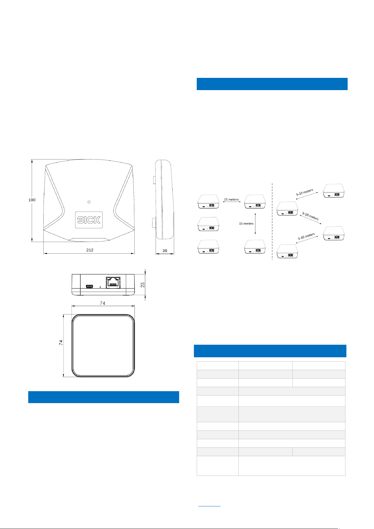
Figure 1. Dimensions of LOCU 212-503
Figure 2. Dimensions of LOCU 200-003
Power over Ethernet
Connect anchor to network switch supporting PoE IEEE
802.3af standard with Ethernet CAT6 cable.
Once the anchor is connected to a stable power supply, a blue
LED blinks several times that indicates the anchor was turned
ON. Then LED is turned OFF.
DC 48 V, Passive PoE
Anchor can be also powered from single or multiple port PoE
injector with DC 48V output. Power supply is injected and
delivered into unused Ethernet pairs (Pairs 4,5 positive
terminal and 7,8 negative terminal).
NOTE: Always use galvanic isolated 48V power adaptor with
short circuit protection for passive PoE injection. Never connect
“Power+Data” injector ports to the computer or other network
devices.
To get the best anchor performance it is recommended to
deploy all anchors to the same hight in a given localization
area and anchor position in the area should follow square
geometry with distance between each anchor from 5-15 m.
The ratio between the two sides of the square should not be
higher than 3:1.
If possible, always maintain a direct Line of Sight between
the tag and the anchors.
For narrow corridors zig-zag positioning is an option. This can
be very useful in narrow corridors, for example in large
warehouses. Be aware that this deployment decreases
precision in the Y axis, so use this option as a last resort:
Figure 3. Square geometry deployment (left) Zig-Zag deployment
(right)
Anchors are typically deployed at the height 3 – 6 meters
above the floor. Recommended mounting is with SICK wall
mount bracket and holder, available as accessory. Mount
LOCU 200-003 with the antenna pointing downwards in order
to get maximum possible performance.
NOTE: Keep a distance from anchor to any walls or metall
parts of at least 15 cm in all directions to avoid significant
degradation of performance.
LOCU 212-503
LOCU 200-003
Size
212 x 190 x 36 mm
74 x 74 x 25 mm
Weight
390 g
72 g
Power supply
PoE 802.3af or DC 48V (passive PoE)
Power
requirements
2.5 W
Operating
conditions
-20° – 60°C
20-85 % humidity
Warm-up time
Immediate
Sensors
Barometer
Placement
Indoor
UWB antenna
Directional CH5
Omnidirectional CH5
UWB Radiated
power
Channel 5, Band: 6240 MHz – 6739.2 MHz
Center Frequency: 6489.6 MHz
-41,3 dBm/MHz
Step 1: Power supply options
Technical data
Step 2: Mounting
Page 3

8024845 QUICKSTART SICK LOCU2 •Subject to change without notice • SICK AG • Waldkirch • Germany • www.sick.com TAGGABLE – LOCALIZATION LOC2xx | SICK 3
SICK AG
Erwin-Sick-Straße 1
D-79183 Waldkirch
www.sick.com
LOCU2
TECHNICAL INFORMATION
All rights reserved. Subject to change without notice.
Regulatory Compliance Information
These products may only be operated in countries for which
approval has been granted.
No.
Country
Type
1
European Union
LOCU2*
2
United States
LOCU200-003
*: all devices of product family comply
Please observe the country-specific information for operation
below.
1 European Union
Simplified EU declaration of conformity
Hereby, SICK AG declares that the radio equipment type
LOCU2 is in compliance with Directive 2014/53/EU.
The full text of the EU declaration of conformity is available at
the following internet address:
https://supportportal.sick.com/products/localization/tagbased-localization/locu/
2 USA
FCC ID: WRMLOCU2A
FCC Compliance statement
For FCC compliance, the following conditions must be me:
• All units must be exclusively used indoors.
• No devices may be installed at any outdoor locations.
This device is designed to be operated with the supplied
antenna. The use of any other antenna with this device is
strictly prohibited and may result in the voiding of the FCC
authorization for this equipment’s operation. It is strictly
forbidden to use of any other antenna than the one SICK AG
has supplied.
This device is compliant with FCC Rules, part 15. Its usage is
subject to the two following conditions:
(1) this device may not be the cause of any harmful
interference, and
(2) this device shall accept any interference received, including
interference that may interfere with its desired operation.
This device is also in compliance with part 15.517 of the FCC
Rules. This equipment may only be used indoors. Usage
outdoors violates 47 U.S.C. 301 and the operator could be
subject to serious legal penalties.
This equipment is only to be installed and used at a 20 cm
minimum distance between the radiator and a person.
Any changes or modifications not expressly approved by the
party responsible for compliance could void the user's authority
to operate this device.
 Loading...