

Page 1

LMS400
LASER MEASUREMENT SENSORS
ONLINE HELP
Page 2

Software version
Copyright
Copyright © 2006 - 2016
SICK AG Waldkirch
Erwin-Sick-Str. 1
79183 Waldkirch
Germany
Trademarks
Windows 98, NT 4.0, 2000, XP, 7, 8, 10 and Internet Explorer are registered trademarks of
Microsoft Corporation in the USA and other countries.
Online help
LMS400 laser measurement sensor
LMS400
Software version described
Software/tool Function Status
Device description LMS400XXXX (jar file)
Device specific software
module for SOPAS ET
V 01.01.20 or higher
SOPAS ET Configuration software V 03.00 or higher
2 © SICK AG · Germany · All rights reserved · Subject to change without notice 8011984/YSZ3/2016-02-04
Page 3

Online help
LMS400
Contents
Table of contents
1 About this document ............................................................................................... 5
1.1 Function of this document .......................................................................................... 5
1.2 Target group ................................................................................................................5
1.3 Depth of information ................................................................................................... 5
1.4 Symbology used .......................................................................................................... 5
2 For your safety ......................................................................................................... 6
2.1 Authorised personnel .................................................................................................. 6
2.2 General safety notes and protective measures ........................................................ 6
3 Configuration ........................................................................................................... 7
3.1 Preparing the configuration ........................................................................................ 7
3.2 Application ................................................................................................................... 8
3.3 Position ........................................................................................................................ 9
3.4 Basic parameters ...................................................................................................... 12
3.5 Advanced parameters ............................................................................................... 15
3.6 Filter ...........................................................................................................................16
3.7 Digital inputs/Trigger ................................................................................................ 18
3.8 Encoder and synchronization ...................................................................................22
3.9 Interfaces ................................................................................................................... 23
4 Level Control .......................................................................................................... 26
4.1 Column width .............................................................................................................26
4.2 Column length ...........................................................................................................27
4.3 Evaluation result ....................................................................................................... 29
4.4 Output message ........................................................................................................ 31
5 Monitor ................................................................................................................... 32
5.1 Scan view ...................................................................................................................32
5.2 Display of the Level Control application .................................................................. 33
6 Service ................................................................................................................... 36
6.1 Version information ................................................................................................... 36
6.2 Operating data ...........................................................................................................36
6.3 System status ............................................................................................................36
7 Glossary ................................................................................................................. 37
8 Index ....................................................................................................................... 39
8011984/YSZ3/2016-02-04
© SICK AG · Germany · All rights reserved · Subject to change without notice 3
Page 4

Figures and tables
LMS400 laser measurement sensor
Online help
Abbreviations
BCC Block Character Check
CAN Controller Area Network = standardised fieldbus system with message-based protocol for
exchanging data
CS Checksum
EEPROM Electrically Erasable Programmable Read-only Memory
FSI Fast Serial Interface = SICK proprietary communication interface
HTML Hypertext Markup Language = page description language on the Internet
LED Light Emitting Diode
LMS SICK AG laser measurement sensor
RAM Random Access Memory = volatile memory with direct access
RIS Remission Information System
ROM Read-only memory (permanent)
SOPAS ET SICK OPEN PORTAL for APPLICATION and SYSTEMS Engineering Tool = configuration
software for the configuration of the LMS400
Figures
Fig. 1: LMS coordinates above a conveyor system .........................................................10
Fig. 2: Gamma angle .........................................................................................................11
Fig. 3: Measurement area ................................................................................................12
Fig. 4: Measured value quality as a function of scan frequency
and angular resolution ...........................................................................................13
Fig. 5: Scanning area of the LMS400 ..............................................................................14
Fig. 6: Errors in the entry of the scan area ......................................................................15
Fig. 7: Scan view ................................................................................................................33
Fig. 8: Display of the Level Control results ......................................................................34
4 © SICK AG · Germany · All rights reserved · Subject to change without notice 8011984/YSZ3/2016-02-04
Page 5

Online help
ATTENTION
LMS400
Figures and tables
1 About this document
Please read this chapter carefully before working with this documentation and the
LMS400 laser measurement sensor.
1.1 Function of this document
This document provides technical personnel information on the configuration and
diagnostics on the LMS400 laser measurement sensor using the SOPAS ET configuration
software.
1.2 Target group
The target group for this document are people such as technicians, service technicians and
engineers who configure and perform diagnostics on the LMS400.
1.3 Depth of information
This document contains information on the configuration, diagnostics and troubleshooting
on the LMS400 laser measurement sensor with the aid of the SOPAS ET configuration
software.
Planning and using measurement sensors such as the LMS400 also require specific
technical skills which are not detailed in this documentation.
When operating the LMS400 laser measurement sensor, the national, local and statutory
rules and regulations must be observed.
1.4 Symbology used
Recommendation Recommendations are designed to give you assistance in the decision-making process with
respect to a certain function or a technical measure.
Note Refer to notes for device special features.
Explanation Explanations provide background knowledge on technical relationships.
M
ENU COMMAND This typeface indicates a term in the SOPAS ET user interface.
Terminal output This typeface indicates messages that the LMS400 outputs via its aux interface.
Take action … Instructions for taking action are shown by an arrow. Read carefully and follow the
instructions for action.
This symbol refers to additional available documentation.
Warning!
A warning indicates an actual or potential hazard. They are designed to help you to prevent
accidents and to protect the device from being damaged.
Read carefully and follow the warning notices!
References to the software show you where to you can make the related setting in SOPAS
ET.
8011984/YSZ3/2016-02-04
© SICK AG · Germany · All rights reserved · Subject to change without notice 5
Page 6

Chapter 2
ATTENTION
2 For your safety
For your safety
LMS400 laser measurement sensor
This chapter deals with your own safety and the safety of the equipment operators.
Please read this chapter carefully before configuring the LMS400.
Online help
2.1 Authorised personnel
The LMS400 laser measurement sensor must be configured and commissioned only by
adequately qualified personnel.
The following qualifications are necessary for the various tasks:
knowledge on the use and operation of devices in the related application (e.g.
conveyors)
knowledge on the software and hardware environment in the related application (e.g.
conveyors)
basic knowledge of the Windows operating system
basic knowledge of an HTML browser (e.g. Internet Explorer)
experience in data transmission modes
2.2 General safety notes and protective measures
Safety notes
Please observe the following items in order to ensure the correct and safe use of the
LMS400 laser measurement sensor.
The notices i n this online he lp ( e.g. on use, mounting, install ation or integr ati on into the
existing machine controller) must be observed.
National/international rules and regulations apply to the installation, commissioning,
use and periodic technical inspections of the laser measurement sensor, in particular:
– work safety regulations/safety rules
– other relevant health and safety regulations
Manufacturers and operators of the sensor are responsible for obtaining and observing
all applicable safety regulations and rules.
The tests must be carried out by specialist personnel or specially qualified and
authorised personnel and must be recorded and documented to ensure that the tests
can be reconstructed and retraced at any time.
6 © SICK AG · Germany · All rights reserved · Subject to change without notice 8011984/YSZ3/2016-02-04
Page 7

Online help
ATTENTION
LMS400
3 Configuration
Note Along with the interactive configuration with the aid of SOPAS ET, you can also configure the
Configuration
The LMS400 laser measurement sensor is adapted to the on-site measurement situation
by means of the configuration. You can configure and test the measurement properties, the
analysis behaviour and the output properties of the sensor as required.
LMS400 using configuration messages.
On this subject please read section “Data communication using messages” in the chapter
“Product description” of the LMS400 operating instructions.
Save parameters permanently
The data are initially saved in RAM in the sensor so that you can check the effect
immediately. On completion of the configuration, you must save the parameters in the
EEPROM of the LMS400
Don’t switch off the voltage supply during configuration!
Switching off the voltage supply during configuration causes all parameters already
configured to be lost.
.
Chapter 3
How to save the parameters permanently in the LMS400:
From the LMS400-XX00 menu, choose the command PARAMETER, SAVE PERMANENT.
In this way the parameters are saved in the EEPROM in the LMS400 and will also be
available after the device is switched off and on again.
3.1 Preparing the configuration
To configure the LMS400 laser measurement sensor, you need:
SOPAS ET configuration software (not included in scope of delivery).
See Internet under: www.sick.com/sopas
PC/notebook (Windows 98, NT 4.0, 2000, XP, Vista, 7, 8 or 10) with Ethernet interface
(RJ45) and optional serial interface (RS232).
Device not included in scope of delivery.
Optional for configuration via serial interface (RS232): a threecore RS232 connection
cable (null modem cable) for connecting PC and LMS400.
Cable not included in scope of delivery.
How to prepare the configuration:
Ensure that the LMS400 laser measurement sensor has been correctly assembled and
that the electrical connections are also correct.
Plan all required settings (operating modes, beam coding, resolution, measured value
filtering, trigger etc.).
8011984/YSZ3/2016-02-04
© SICK AG · Germany · All rights reserved · Subject to change without notice 7
Page 8

Chapter 3
Configuration
LMS400 laser measurement sensor
Connect the PC/notebook with the aux interface of the LMS400. The connection of the
PC is described in chapter “Electrical installation” in the LMS400 operating
instructions.
Install the SOPAS ET configuration software.
Note The second genera tion of SOPAS ET (version 2.38.3) can continue to be used, although
support for it is no longer being provided. To receive updates or support, please use the
latest version, i.e., the third generation of SOPAS ET (version 3.xx).
Download and installation of SOPAS ET
The configuration software SOPAS ET, the current system prerequisites for the PC, and the
instructions for downloading the software and the device description file(s) can be found in
the Web at: www.sick.com/sopas.
1. Start PC.
2. Download and install version V3.x of the SOPAS ET configuration software from the
online product page for the software by following the instructions provided there.
Administrator rights may be required on the PC to install the software.
3. Start the “SOPAS ET” program option after completing the installation.
Path: C:\Program Files (x86)\SICK\SOPAS ET\SopasET.exe or via Windows search.
4. Install the device driver (SDD) in the device catalog using the wizard (gear symbol). The
*.jar file can be obtained from the online repository if an Internet co nnection is present.
5. In the device search list, establish a connection between SOPAS ET and the LMS400
using the search settings. To do this, select the LMS4xx family of devices and select the
default IP address 192.168.0.1 when connecting for the first time. The device is
detected and can now be integrated into a project for configuration purposes.
Note The installation file for SOPAS ET and the *.jar file for the device driver can also be
exported to a data card in order to install them on another PC when there is no Internet
connection.
The LMS4xx does not support Automatic Private IP Addressing (auto-IP). For this reason,
the device is not detected by the default search. To ensure the device search is
successful, the correct IP address and a sufficiently precise address range must be
specified. It is possible to save a search setting that has been set up specifically for this
purpose under a separate name (default: IP address = 192.168.0.1, subnet mask =
255.255.255.0).
Online help
3.2 Application
The LMS400 can be operated in two modes:
as a laser measurement sensor for the acquisition and output of pure measured data,
e.g. to a host
using the Level Control application for completeness and contents checks, e.g. on
containers
On this subject please read the chapter “Level Control” of the LMS400 operating
instructions.
If you select the Level Control application, additional and different parameters will be
displayed:
see section 3.3 “Position” on page 9
see chapter 4 “Level Control” on page 26
8 © SICK AG · Germany · All rights reserved · Subject to change without notice 8011984/YSZ3/2016-02-04
Page 9

Online help
LMS400
y
z
LMS400
Configuration
see section 3.6.4 “Filter for the Level Control application” on page 18
see section 3.7.7 “Internal gate” on page 22
How to select the Level Control application:
Open in the PROJECT TREE, LMS400-XX00, PARAMETER the device page APPLICATION.
In the A
The additional device pages for the application are displayed in the project tree.
PPLICATION field select the option LEVEL CONTROL.
Chapter 3
3.3 Position
Note The POSITION device page is only displayed if you have activated the Level Control application
(see 3.2 on page 8).
On this device page you can enter the coordinates and angle of the LMS400 over the
conveyor system and in this way define the zero point for the system.
You can also define the relevant working area as the measurement area.
3.3.1 Coordinates
As delivered the zero point for the distance measurement is at the origin of the laser
(marked by a dot on the top and underside of the housing).
The Level Control application requires a global zero point to which all other settings refer
(e.g. right edge of the conveyor system as seen in the transporting direction). You can define
this zero point with the aid of the X, Y and Z coordinates.
As a rule this zero point is at the bottom right edge of the conveyor system as seen in the
transporting direction.
8011984/YSZ3/2016-02-04
Fig. 1: LMS400 coordinates above a conveyor system
X coordinate
Enter the value 0 mm in the field.
© SICK AG · Germany · All rights reserved · Subject to change without notice 9
Page 10
Chapter 3
Configuration
LMS400 laser measurement sensor
Online help
Y coordinate
Enter in the field the distance between the vertically incident beam and the zero point
for the measurement.
A plumb line positioned in the middle of the sensor is helpful.
Z coordinate
Enter in the field the distance from the zero point for the measurement to the top edge
of the transporting area.
Note There is an installation setup for the configuration of the position of the LMS400. Start the
assistant on the LMS400_XX00 menu, C
OMMISSIONING, START INSTALLATION HELP.
On this subject please read the section “Determining the coordinates using the installation
setup” in the chapter “Level Control” of the LMS400 operating instructions”.
How to define the coordinates:
Open in the PROJECT TREE, LMS400-XX00, PARAMETER the device page POSITION.
Enter the related values in the X
COORDINATE, Y COORDINATE, Z COORDINATE fields.
3.3.2 Angle
Using the fields on the device page you can define the angle at which the LMS400 is
mounted in relation to the conveyor system.
Alpha
Enter 90° for the A
LPHA angle.
Beta
Enter 0° for the B
ETA angle.
Gamma
Read the angle G
AMMA on the mounting kit for the LMS400, in general this angle is 0°.
Note An installation setup is available for the definition of the angle Gamma. Start the assistant
on the LMS400_XX00 menu, C
OMMISSIONING, START INSTALLATION HELP.
On this subject please read the section “Determining the coordinates using the installation
setup” in the chapter“Level Control” of the LMS400 operating instructions.
10 © SICK AG · Germany · All rights reserved · Subject to change without notice 8011984/YSZ3/2016-02-04
Page 11

Online help
Gamma
Z
LMS400
Y
Top border,
e.g. 500 mm
Bottom border,
usually 0 mm
Right border,
usually 0 mm
Left border,
e.g. 1200 mm
Measurement
area
Zero point
LMS400
Configuration
Fig. 2: Gamma angle
How to define the angles of the LMS400:
Chapter 3
Open in the PROJECT TREE, LMS400-XX00, PARAMETER the device page POSITION.
In the A
3.3.3 Measurement area
You define the working area relevant for the Level Control application as the measurement
area. You define for this measurement area a left and right border as well as a top and
bottom border. All four values refer to the global zero point defined previously.
NGLE area enter the values for the measurement area borders in the fields.
8011984/YSZ3/2016-02-04
Fig. 3: Measurement area
Notes Ensure that the zero point is on the right and Y extends to the left. For this reason the
value for the left border is always greater than the value for the right border.
The bottom border can also have a negative value, e.g. to include the conveyor system
in the evaluation.
© SICK AG · Germany · All rights reserved · Subject to change without notice 11
Page 12

Chapter 3
Configuration
LMS400 laser measurement sensor
Online help
All measured values outside the measurement area are invalid and are not taken into
account.
How to define the measurement area:
Open in the PROJECT TREE, LMS400-XX00, PARAMETER the device page POSITION.
In the M
EASUREMENT AREA area enter the values for the measurement area borders in the
fields.
3.4 Basic parameters
To be able to perform measurements with the LMS400, the basic parameters must be
configured. For this purpose configure the size of the scanning area, the angular resolution
and the scanning frequency in the scan settings.
3.4.1 Current device parameters
The C
URRENT DEVICE PARAMETER area indicates the scanning frequency and the angular
resolution actually set and the resulting measured value quality.
Note Values are only displayed if you configure a device online, that is the PC is connected to the
device.
Measured value quality
You cannot configure the measured value quality directly. The sensor calculates the
measured value quality based on the configured angular resolution and the scanning
frequency.
The measured value quality should ideally be 7. A higher value corresponds to a better
measured value quality. If the measured value quality determined from the parameters is
lower than 7, the sensor is no longer compliant with the values given in the technical data.
12 © SICK AG · Germany · All rights reserved · Subject to change without notice 8011984/YSZ3/2016-02-04
Page 13
Online help
Angular resolution
Scanning frequency
Better measured
value quality
Lower measured value quality
M
e
a
s
u
r
e
d
v
a
lu
e
q
u
a
lit
y
7
LMS400
Configuration
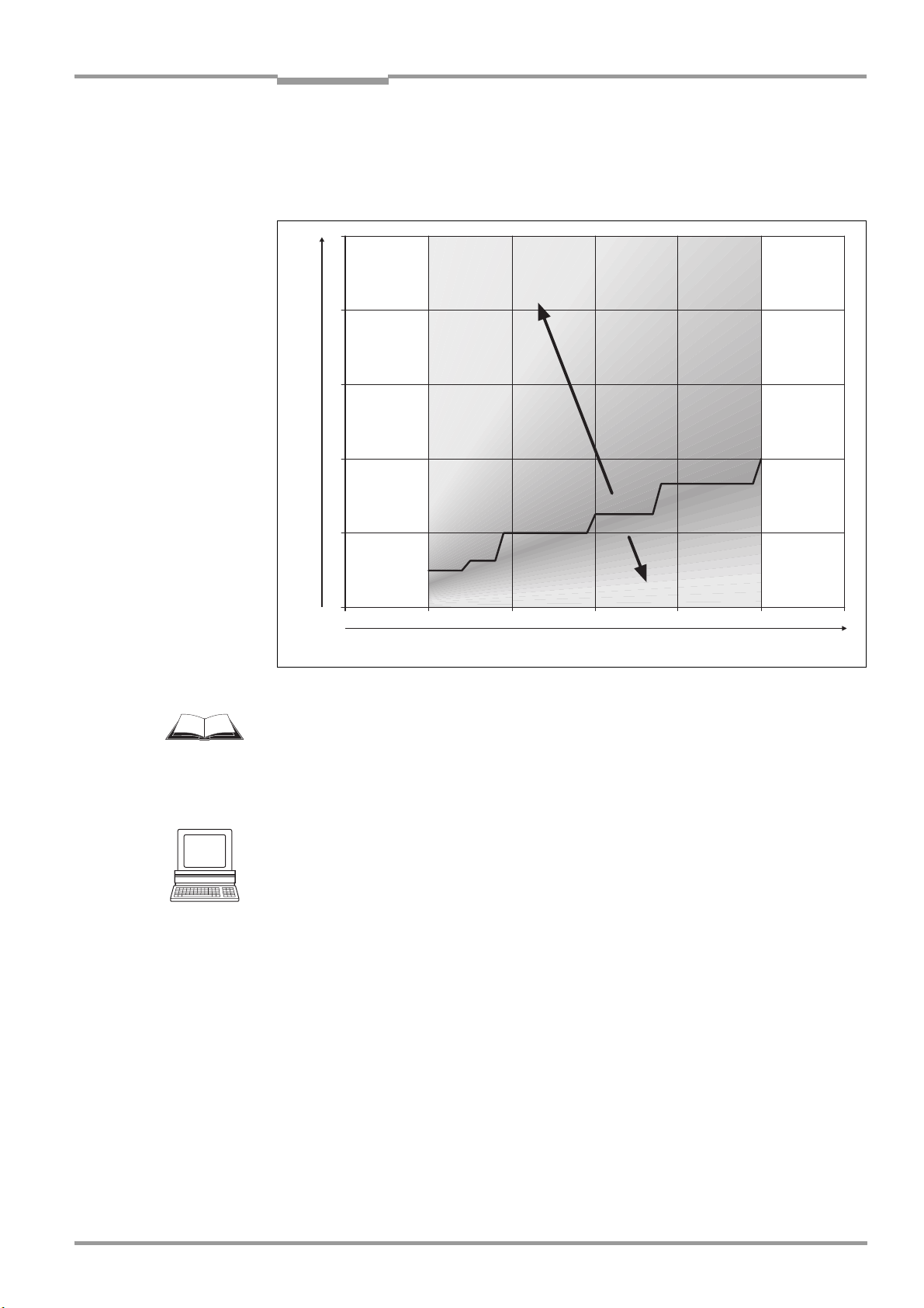
At a high scan frequency and fine angular resolution, the sensor provides more measured
values with a tendency to a lower measured value quality than for a coarse angular
resolution and low scan frequency. You can estimate the achievable measured value quality
based on the following diagram.
Chapter 3
Fig. 4: Measured value quality as a function of scan frequency and angular resolution
In the LMS400 operating instructions in the section “Measured value quality” of the chapter
“Product description” you will find tables with the measured value qualities given by the
angular resolution and scanning frequency.
How to display the current device parameters:
Open in the PROJECT TREE, LMS400-XX00, PARAMETER the device page BASIC PARAMETER.
The C
URRENT DEVICE PARAMETER area indicates the SCANNING FREQUENCY and the ANGULAR
RESOLUTION actually set and the resulting MEASURED VALUE QUALITY.
Recommendation Choose the configuration that provides the highest measured value quality.
Scanning frequency wizard
Determine scanning frequency and angular resolution using the scanning frequency wizard.
There are two options in the scanning frequency wizard:
Choose the option A
in °.
Choose the option F
Various configuration options are displayed in the next step. The recommended options
(measured value quality 7) have a green dot in the R
Once you have completed the wizard the new parameters will be displayed in the C
DEVICE PARAMETER area.
NGULAR RESOLUTION and in the VALUE field enter the required angle
REQUENCY and in the VALUE field enter the required frequency in Hz.
ECOMMENDED column.
URRENT
8011984/YSZ3/2016-02-04
© SICK AG · Germany · All rights reserved · Subject to change without notice 13
Page 14

Chapter 3
Starting angle 55°
to 123°
Angular range 2° to 70°
55° 123°
Configuration
LMS400 laser measurement sensor
How to open the scanning frequency wizard:
Open in the PROJECT TREE, LMS400-XX00, PARAMETER the device page BASIC PARAMETER.
Click in the C
Note On master/slave operation (see “Master/slave configuration (synchronization)” on
page 22), master and slave must be configured to the same scanning frequency and
angular resolution.
3.4.2 Scan settings
Scanning area
The scanning area of the LMS400 covers an angle of maximum 70°, the minimum starting
angle is 55° (see Fig. 5). Using the S
the scan area.
URRENT DEVICE PARAMETER area the SCANNING FREQUENCY WIZARD button.
TARTING ANGLE and ANGULAR RANGE fields you can adjust
Online help
Fig. 5: Scanning area of the LMS400
How to define the scanning area:
Open in the PROJECT TREE, LMS400-XX00, PARAMETER the device page BASIC PARAMETER.
In the S
field.
Enter a value between the maximum 70° und minimum 2° in the A
Explanation The values that can be entered are dependent on each other. If, for example, 95° are given
as the S
enter 60° as the angular range, the starting angle can be a maximum of 65°.
CAN SETTINGS area enter a value between 55° und 123° in the STARTING ANGLE
NGULAR RANGE field.
TARTING ANGLE, the ANGULAR RANGE can only be a maximum of 30°. If, for instance you
14 © SICK AG · Germany · All rights reserved · Subject to change without notice 8011984/YSZ3/2016-02-04
Page 15

Online help
LMS400
Configuration
Invalid entries are displayed in SOPAS ET with a red border (see Fig. 6).
Fig. 6: Errors in the entry of the scan area
3.4.3 Other settings
Chapter 3
In the M
ISCELLANEOUS SETTINGS area you can define a device name for the LMS400. The
device name will then be displayed on the project tree. Use this field, for example, to make
it easier to differentiate between different applications.
How to enter a device name:
Open in the PROJECT TREE, LMS400-XX00, PARAMETER the device page BASIC PARAMETER.
In the M
characters in the D
ISCELLANEOUS SETTINGS area enter a device name with a maximum of 16
EVICE NAME field.
Press the Return key.
If the PC is connected to the LMS400 and the device is switched online, the device name is
displayed in the project tree.
3.5 Advanced parameters
Note The advanced parameters are only available in the “Authorised client” user level.
Enable extended RIS detectivity
If you want to measure objects with remission values smaller or higher than the values given
in the data sheet for the LMS400, you can extend the so-called Remission-InformationSystem (RIS) in the LMS400. In this way the RIS facilitates, e.g., the improved detection of
dark or lighter bodies with reduced accuracy.
8011984/YSZ3/2016-02-04
On this subject please read the section “Extended RIS detectivity” in the chapter “Product
description” of the LMS400 operating instructions .
For measured values that are measured using extended RIS detectivity the following
applies:
The distance value may not have the defined measuring accuracy.
The same measurement point/the same object will not necessarily be detected by
another LMS400 because the remission value determined is dependent on the factory
calibration of the sensor, outside the specified range the calibration may be subject to
minor variations.
With extended RIS detectivity, your application must therefore evaluate, based on
additional criteria, whether the distance value is to be used or not.
© SICK AG · Germany · All rights reserved · Subject to change without notice 15
Page 16

Chapter 3
Configuration
How to activate the extended RIS detectivity:
Open in the PROJECT TREE, LMS400-XX00, PARAMETER, BASIC PARAMETER the device page
A
DVANCED PARAMETERS.
Select there in the A
DVANCED DEVICE PARAMETERS area the option DARK or LIGHT.
3.6 Filter
The LMS400 has digital filters for the pre-processing and optimisation of the measured
distance values.
Notes You can combine the filters as required.
If several filters are active, then the filters act one after the other on the result of the
previous filter. The processing in this case follows the following sequence:
– edge filter
– median filter
–range filter
–mathematical filter
Active filter functions change the measured values that are output. It is not possible to
convert filtered output values back to the original measured values.
Online help
LMS400 laser measurement sensor
3.6.1 Contour filter
Edge filter
The edge filter prevents incorrect/extreme distance values at edges that result from it not
being possible to determine a distance value for the previous or next point (e.g. if the
previous/next measured point was too dark or outside the measuring range of 3 metres).
With the edge filter enabled, the LMS400 also sets a distance value to 0 at each edge.
On this subject please read the section “Edge filter” in the chapter “Product description” of
the LMS400 operating instructions.
Note Using the edge filter, points can be completely suppressed at the outer edges of the object.
In this case the width determined for an object is too narrow by up to 2 × the angular
resolution.
How to activate the edge filter:
Open in the PROJECT TREE, LMS400-XX00, PARAMETER the device page FILTER.
Select there in the C
ONTOUR area the option ACTIVATE EDGE FILTER.
16 © SICK AG · Germany · All rights reserved · Subject to change without notice 8011984/YSZ3/2016-02-04
Page 17

Online help
LMS400
Configuration
Median filter
Note The median filter is not available if on the A
was selected (see 3.2 “Application” on page 8).
The median filter reduces individual extreme values over the entire measurement line by
outputting the median for each measurement point (not: the mean/average) from a 3 × 3
matrix. The matrix comprises nine measured values: The distance values for the point and
its neighbouring points, as well as the distance values determined for these points in the
previous and subsequent scan.
On this subject please read the section “Median filter” in the chapter “Product description”
of the LMS400 operating instructions.
How to activate the median filter:
Open in the PROJECT TREE, LMS400-XX00, PARAMETER the device page FILTER.
Select there in the C
ONTOUR area the option ACTIVATE MEDIAN FILTER.
Chapter 3
PPLICATION device page the LEVEL CONTROL option
3.6.2 Range filter
Note The range filter is not available if on the A
has been selected (see 3.2 “Application” on page 8).
The range filter reduces the number of valid measured values by only outputting distance
values that are within a specific distance range. For other measured values the filter
delivers the distance value 0 and the remission value 0 as the result.
How to activate the range filter
:
Open in the PROJECT TREE, LMS400-XX00, PARAMETER the device page FILTER.
Select there in the R
In the M
IN. MEASUREMENT DISTANCE field enter a value of at least 700 mm and maximum
ANGE area the option ACTIVATE RANGE FILTER.
3000 mm.
Then in the M
M
IN. MEASUREMENT DISTANCE field and maximum 3000 mm.
AX. MEASUREMENT DISTANCE field enter a value larger than the value in the
3.6.3 Mathematical filter
The mean filter smooths the distance value. For this purpose the filter forms the arithmetic
mean over several scans. The number of scans can be configured.
On this subject please read in the LMS400 operating instructions chapter “Product
description”, section “Mean filter”.
PPLICATION device page the LEVEL CONTROL option
Recommendation Use the mean filter together with the median filter. In this way individual outliers will be
8011984/YSZ3/2016-02-04
smoothed in advance by the median filter.
How to activate the mean filter:
Open in the PROJECT TREE, LMS400-XX00, PARAMETER the device page FILTER.
Select there in the M
In the N
© SICK AG · Germany · All rights reserved · Subject to change without notice 17
UMBER OF AVERAGED SCANS field enter a value of at least 2 and maximum 100.
ATHEMATICAL area the option ACTIVATE MEAN FILTER.
Page 18

Chapter 3
Configuration
LMS400 laser measurement sensor
Online help
3.6.4 Filter for the Level Control application
Z median filter
The Z median filter forms a 3 by 3 median from the Z values for the measured points (and
not, like the median filter, from the polar distance values).
How to activate the Z median filter:
Open in the PROJECT TREE, LMS400-XX00, PARAMETER the device page FILTER.
Select there in the L
EVEL CONTROL area the option ACTIVATE Z-MEDIAN FILTER.
Interval distance
At large column lengths and low conveyor speed a quantity of scans will be obtained that is
inappropriate for the evaluation of a column in the X direction. For this reason with the aid
of an interval you can define the magnitude of the distance between two scans that are to
be used for the measurement.
How to configure the interval distance:
Open in the PROJECT TREE, LMS400-XX00, PARAMETER the device page FILTER.
Enter there in the L
EVEL CONTROL are in the INTERVAL DISTANCE field the necessary value
in mm.
3.7 Digital inputs/Trigger
Using the settings on the device page you can define whether the start and end of the
measurement are defined by triggers.
You can select whether the settings for the triggering are to be time or distance controlled.
You can define the sources for the triggering and if necessary the logic and debounce for
the digital inputs.
You can also define whether the laser in the LMS400 is switched on by a trigger or remains
switched on continuously.
3.7.1 Operating principle of the LMS400
Note You can only change the settings if the Level Control application is activated (see 3.2 on
page 8).
The settings define what determines the start and end of the measurement.
Free running
In case of free running operating mode, measured value messages are output after the
LMS400 has received the measured value request until the output of measured values
is stopped by a stop message. Measurements are performed continuously or with
internal gate between the reception of the measured value request and the reception
of the stop message (see 3.7.7 on page 22).
Triggered (gate)
If you use an external gate, then the start and end of the gate (that is e.g. switching on
and off a photoelectric switch on a digital input) define the length of the columns.
18 © SICK AG · Germany · All rights reserved · Subject to change without notice 8011984/YSZ3/2016-02-04
Page 19

Online help
LMS400
Configuration
3.7.2 Common settings
Chapter 3
In the C
OMMON SETTINGS area you can select whether the remaining settings for the triggering
are to be time or track controlled.
Note The method of control can only be changed in the “Service” user level.
In the case of time-dependent control, enter the debounce, delay, etc. in ms.
In the case of track-dependent control, enter the debounce, delay, etc. in mm.
The debounce, delay, etc. are determined for track controlled triggering using the actual
distance determined by the encoder (see 3.8.2 on page 23). Velocity fluctuations in the
conveyor system are then irrelevant.
How to define the general settings:
Open in the PROJECT TREE, LMS400-XX00, PARAMETER the device page DIGITAL
I
NPUTS/TRIGGER.
In the C
OMMON SETTINGS area select whether the measurement is to be triggered time or
track controlled.
3.7.3 Digital inputs
The digital inputs 1 and 3 (IN1 and IN3) are used for triggering the LMS400, for example
using external switches or sensors. To bridge bounce times on external switches, you can
configure an input delay for the inputs. For both inputs you can also select whether they are
to be active high or active low.
You will find the pin assignment for the inputs in the LMS400 operating instructions in the
chapter “Electrical installation”.
Note Depending on whether the measurement is triggered time or track controlled (see 3.7.2
“Common settings” on page 19), you must enter the debounce for the inputs in ms or mm.
How to configure the settings for the digital inputs 1 and 3:
Open in the PROJECT TREE, LMS400-XX00, PARAMETER the device page DIGITAL
I
NPUTS/TRIGGER.
Select under D
is to be
In the D
IGITAL INPUT SETTINGS in the LOGIC selection field, whether the related input
ACTIVE HIGH or ACTIVE LOW.
IGITAL INPUT SETTINGS area in the DEBOUNCING IN1 or DEBOUNCING IN3 field enter the
path for the conveyor system in mm that is necessary to debounce the switches or
sensors connected.
Or
In the D
IGITAL INPUT SETTINGS area in the DEBOUNCING IN1 or DEBOUNCING IN3 field enter the
input delay in ms that is necessary to debounce the switches or sensors connected.
Note You must add the input delay to the start delay for the triggering (see 3.7.4 “Gate” on
page 20).
8011984/YSZ3/2016-02-04
© SICK AG · Germany · All rights reserved · Subject to change without notice 19
Page 20

Chapter 3
Configuration
LMS400 laser measurement sensor
Online help
3.7.4 Gate
The LMS400 provides several trigger sources for gate control. These can start or stop the
measurement immediately or initiate a delayed start and/or stop of the measurement.
On this subject please read section “Control of the measurement process using a gate” in
the chapter “Product description” of the LMS400 operating instructions.
SOPAS ET provides several trigger sources for gate control:
digital inputs
software trigger
CAN BUS
test trigger (see 3.7.6 “Advanced I/O settings” on page 22)
triggering by the LMS400 master
The trigger sources can stop or start the measurement immediately, or trigger a delayed
measurement start and/or stop.
In addition, you can extend the gate produced by the triggering with a so-called expansion
distance.
Note Depending on whether the measurement is triggered time or track controlled (see 3.7.2
“Common settings” on page 19), you can enter the delay and expansion as a distance or as
a time.
Example:
A photoelectric switch is mounted 1000 mm in front of the scan line. You initialise the start
of the measurement on the entry of the object into the photoelectric switch. You initialise
the measurement when the object leaves the photoelectric switch.
1000 mm are entered as the distance delay. In this way the measurement is actually only
started when the object reaches the scan line, and only stops when it leaves the scan line.
If an expansion distance of 50 mm is now entered, the measurement starts 50 mm before
the object reaches the scan line and stops 50 mm after it leaves the scan line.
You can start and stop the measurement using one trigger source or you can use one trigger
source to start and a second to stop the measurement.
How to configure a gate:
Open in the PROJECT TREE, LMS400-XX00, PARAMETER the device page DIGITAL
I
NPUTS/TRIGGER.
In the G
ATE SETTINGS area in the START TRIGGER SOURCE and STOP TRIGGER SOURCE selection
field select the source for the triggering.
Configure as necessary
DISTANCE DELAY and EXPANSION DISTANCE.
Gate for the Level Control application
In the Level Control application the start and stop of the gate (that is e.g. switching on and
off a photoelectric switch) define the length of the columns or the length over which
columns are generated (see 3.7.7 on page 22).
On this subject please read the section “Evaluation in X direction” in the chapter “Level
Control” of the LMS400 operating instructions.
20 © SICK AG · Germany · All rights reserved · Subject to change without notice 8011984/YSZ3/2016-02-04
Page 21

Online help
LMS400
Configuration
Chapter 3
3.7.5 Laser control
With laser control active, the switching on of the laser is controlled by the gate configured
or by a dedicated source.
On this subject please read the section “Laser control” in the chapter “Product description”
of the LMS400 operating instructions.
G
ATE CONTROLLED
The laser is controlled by start and stop trigger source configured in the Gate settings
area (see 3.7.4 “Gate” on page 20).
D
EPENDENT ON SOURCE
The laser is controlled by the source configured in the SOURCE selection field. The control
is independent of the settings made in the G
ATE SETTINGS area.
Control of the laser by a dedicated source
As soon as the LMS400 has calculated, based on encoder pulses (see 3.8.2 “Increment
configuration” on page 23) that a certain distance (the laser off distance) has been
reached, it switches off the laser. In addition, a laser timeout ensures that after a certain
amount of time, the laser is switched off in all circumstances.
If, between switching on and off the laser, the start trigger is set again (for instance by a new
object passing a photoelectric switch), the distance calculation and the laser switch off
delay counter are set to zero and re-started. The laser therefore remains switched on.
How to configure the laser control:
Open in the PROJECT TREE, LMS400-XX00, PARAMETER the device page DIGITAL
I
NPUTS/TRIGGER, area LASER CONTROL.
In the L
In the case of independent laser control, in the S
I
that are connected to inputs. Select the S
ASER CONTROL area select the GATE CONTROLLED or INDEPENDENT option.
OURCE selection field select the DIGITAL
NPUT IN1 or DIGITAL INPUT IN3 option if the laser is to be triggered by switches or sensors
OFTWARE TRIGGER option if the laser is to be
triggered using a message over one the interfaces.
In the L
ASER TIMEOUT field enter the time in minutes after which the laser is to be
switched off.
In the L
ASER OFF DISTANCE field enter the distance after which the laser is to be switched
off.
Note The LMS400 can count a maximum of 30000 encoder pulses from the time the trigger
is activated until the lasers are switched off. With the encoder resolution of 0.2
mm/incr. of the recommended encoder this results in 30000 × 0.2 mm = 6000 mm.
8011984/YSZ3/2016-02-04
© SICK AG · Germany · All rights reserved · Subject to change without notice 21
Page 22

Chapter 3
Configuration
3.7.6 Advanced I/O settings
Online help
LMS400 laser measurement sensor
In the T
for the test trigger.
Here …
the pulse length defines the length between the start of triggering and the stop of
the pause length defines the pause between two triggers.
Using the test trigger you can trigger the gate and the laser control to perform the test
measurements.
How to configure the test trigger settings:
Open in the PROJECT TREE, LMS400-XX00, PARAMETER, DIGITAL INPUTS/TRIGGER the device
Enter the required values in the P
3.7.7 Internal gate
Note The I
Control (see 3.2 on page 8).
If you use an internal gate, the G
G
ATE OFF parameter defines the gap between two columns.
The columns can be “generated” continuously by the internal gate or instead limited by an
external gate (see 3.7.4 on page 20).
If you use an external gate, the start and end of the gate define the start and end of column
generation. Between start and end the internal gate defines the length of the columns.
EST TRIGGER SETTINGS area you can configure the pulse length and the pause length
triggering.
page A
DVANCED IO SETTINGS.
ULSE LENGTH and PAUSE LENGTH fields.
NTERNAL GATE device page is only displayed if you have activated the application Level
ATE ON parameter defines the length of the columns and the
How to configure an internal gate:
Open in the PROJECT TREE, LMS400-XX00, PARAMETER, DIGITAL INPUTS/TRIGGER the device
page A
DVANCED IO SETTINGS.
In the I
NTERNAL GATE area select the option INTERNAL GATE and define the columns using
the G
ATE ON and GATE OFF fields.
3.8 Encoder and synchronization
3.8.1 Master/slave configuration (synchronization)
If you use two LMS400 as master and slave over the “System” connection, then you must
configure one device as master and the other one as slave.
Notes On master/slave operation, master and slave must be configured to the same scanning
frequency and angular resolution (see “Scan settings” on page 14).
Once the mirrors have run up, master and slave must synchronise with each other. This
can tak e up to 120 se conds. Not e that until synchronisation is complete, the measured
values supplied by the two devices are not synchronised.
Phase
On the use of two LMS400 in a master/slave system it may occur that one LMS400 received
the beams from the other LMS400 and is affected by the beams.
22 © SICK AG · Germany · All rights reserved · Subject to change without notice 8011984/YSZ3/2016-02-04
Page 23

Online help
LMS400
Configuration
Chapter 3
To significantly reduce the probability of mutual interference, the two LMS400 can
synchronise with each other so that their rotating mirrors rotate offset from each other by a
specific angle. This angle is termed the “Phase”.
Recommendation On the master set a phase of 35°. Then the mirrors will rotate offset by one half field of view.
On this subject please read the section “Master/slave operation” in the chapter “Product
description” of the LMS400 operating instructions.
How to configure the devices as a master or slave:
Open in the PROJECT TREE, LMS400-XX00, PARAMETER the device page INCREMENT
CONFIG./SYNC.
In the S
M
Enter the phase offset for the synchronisation in the P
YNCHRONISATION MASTER/SLAVE area in the selection field TYPE select the option
ASTERSYNC for the master and SLAVESYNC for the slave.
HASE field of the master.
3.8.2 Increment configuration
The LMS400 can use the pulses from an encoder to determine the position or velocity. As
an alternative, it is also possible to enter a constant velocity that can be used for making
the position calculations.
On this subject please read the section “Connection of encoders” in the chapter “Product
description” of the LMS400 operating instructions chapter.
How to configure the evaluation of the encoder:
Open in the PROJECT TREE, LMS400-XX00, PARAMETER the device page INCREMENT
CONFIG./SYNC.
In the I
NCREMENT SETTINGS area in the selection field INCREMENT SOURCE select between:
–D
EACTIVATED
–CONSTANT VELOCITY
–ENCODER ON IN2
–E
NCODER ON IN2, IN4 (DIRECTION VIA LEVEL)
–E
NCODER ON IN2, IN4 (DIRECTION VIA PHASE)
If you have selected an encoder as an incremental source, enter the resolution of the
encoder in mm/increment in the E
If you have selected C
C
ONSTANT VELOCITY field.
ONSTANT VELOCITY, enter the constant velocity in m/s in the
NCODER RESOLUTION field.
3.9 Interfaces
The LMS400 has different interfaces for the configuration and the transmission of
measured values. You can configure the LMS400 and also receive measured values via
each of these interfaces.
Notes It is only possible to output all measured values of a scan in real-time using the Ethernet
interface.
The aux interface is primarily intended to be used to provide a safe data connection for
setting parameters, for this reason the interface parameters for the aux interface
cannot be changed.
8011984/YSZ3/2016-02-04
© SICK AG · Germany · All rights reserved · Subject to change without notice 23
Page 24

Chapter 3
Configuration
LMS400 laser measurement sensor
Online help
3.9.1 Host interface
The host interface allows the configuration of the LMS400 as well as the output of
measured values. The interface parameters are freely configurable. The factory setting for
the host interface is as follows:
RS232
9600 Baud
8 data bits
1 stop bit
no parity
With the aid of the fields and selection fields on the device page define the parameters for
the host interface so that they match the interface in the application connected.
How to configure the host interface:
Note The parameters for the host interface can only be configured using SOPAS ET if the PC is
connected via the aux interface or the Ethernet interface. If the PC is connected using the
host interface, the parameters described below are hidden.
Open in the PROJECT TREE, LMS400-XX00, PARAMETER, INTERFACE the device page SERIAL.
In the S
between 1200 and 115200 B
With the aid of the S
ERIAL HOST INTERFACE area select in the BAUD RATE selection field a baudrate
AUD.
TOP BITS selection field define whether the interface uses one or two
stop bits.
With the aid of the D
ATA/PARITY BITS selection field define the relationship between data
and parity bits.
In the H
ARDWARE selection field (depending on the hardware used) select RS232 or
RS422/RS485.
In the B
LOCK CHECK selection field define whether the block check byte is sent and if yes,
whether it is sent before or after the stop character.
Define the start and stop characters for sending and receiving messages over the host
interface. In this way, for example, you can use two stop bytes (e.g. to end messages
with CR/LF).
For this purpose click the C
HANGE button and, in the window that opens, select the
character (if only one stop character is to be used, then select NUL for the second
character).
3.9.2 Ethernet interface
The Ethernet interface has a data transmission rate of 10 MBaud (10BaseT). The interface
is a TCP/IP peer to peer interface. Only half duplex is supported. Please ensure that the
interface of your application is set to half duplex. The factory setting for the Ethernet
interface is as follows:
IP
ADDRESS: 192.168.0.1
TCP/IP
S
PORT: 2111
UBNET MASK: 255.255.255.0
Recommendation To check the availability of the LMS400, at the command prompt on the PC enter ping IP
address, e.g. ping 192.168.0.1.
How to configure the Ethernet interface:
24 © SICK AG · Germany · All rights reserved · Subject to change without notice 8011984/YSZ3/2016-02-04
Page 25

Online help
LMS400
Configuration
Chapter 3
Note Changes to the Ethernet interface parameters will only be effective after the LMS400 is re-
started. The CoLa protocol cannot be changed using the Ethernet interface.
Open in the PROJECT TREE, LMS400-XX00, PARAMETER, INTERFACE the device page
E
THERNET.
In the E
If you access the LMS400 via a gateway in your network, in the D
THERNET area enter an IP address for the LMS400 in the IP ADDRESS field.
EFAULT GATEWAY field
enter the gateway’s IP address. Otherwise leave the default numbers 0.0.0.0.
In the S
UBNET MASK field enter the number for the network segment to which the
application connected belongs.
In the MAC
In the TCP/IP
In the C
ADDRESS field the Media Access Control address for the LMS400 is displayed.
PORT enter the port over which the application connected communicates.
OLA PROTOCOL selection field select whether the data communication is binary or
in ASCII.
Recommendation You should not change the default values in the TCP/IP
PORT and COLA PROTOCOL fields.
8011984/YSZ3/2016-02-04
© SICK AG · Germany · All rights reserved · Subject to change without notice 25
Page 26

Chapter 4
4 Level Control
Level Control
LMS400 laser measurement sensor
Online help
With the aid of the Level Control application, for instance levels in containers, the complete
filling of pallets or the complete emptying of transport containers can be checked.
On this subject please read the chapter“Level Control” in the LMS400 operating
instructions.
4.1 Column width
To be able to evaluate the measurement results in the measurement area, you divide the
measurement area into columns. During this process it is important that you adjust the size
of the columns to suit your application.
4.1.1 Mode
In the M
ODE area you first define whether you want set the column width as equidistant or
customised.
With the user-defined setting the C
OLUMNS field is also displayed. In this field choose the
column numbers you want to configure as C
The values entered on the M
page 11) in the L
EFT BORDER and RIGHT BORDER fields.
EASUREMENT AREA device page are displayed (see 3.3.3 on
How to define the column division mode:
Open in the PROJECT TREE, LMS400-XX00, PARAMETER, LEVEL CONTROL the device page
C
OLUMN WIDTH.
In the M
C
ODE area select in the PARAMETERIZATION field between EQUIDISTANT and
USTOMIZED.
4.1.2 Equidistant division
Note For equidistant column division, in the M
(see 4.1.1).
Define the number of columns in the N
number of columns. You can see the resulting width of the individual columns in the W
field.
Enter for all columns a common switching point with hysteresis, an evaluation mode and a
valid quality applicable to all columns.
USTOMISED (see 4.1.3 on page 27).
ODE area y ou m ust se lect the p aram eter EQUIDISTANT
UMBER field. The measuring area is divided by the
IDTH
On this subject please read the section “Evaluation in Y direction” in the chapter “Level
Control” of the LMS400 operating instructions.
How to define equidistant column division:
Open in the PROJECT TREE, LMS400-XX00, PARAMETER, LEVEL CONTROL the device page
C
OLUMN WIDTH.
In the E
necessary values in the Z-L
Select the mode for the evaluation in the C
QUIDISTANT area enter in the NUMBER field the number of columns as well as the
EVEL, Z-HYST and Y-QUALITY fields.
ALC. MODE field.
26 © SICK AG · Germany · All rights reserved · Subject to change without notice 8011984/YSZ3/2016-02-04
Page 27

Online help
LMS400
Level Control
4.1.3 Customised division
Chapter 4
Notes For customised column division you must choose in the M
C
USTOMISED (see 4.1.1 on page 26).
ODE area the parameter
First the columns 1 to 10 are displayed for configuration. You can select further
columns (11 to 20 and 21 to 30) in the M
ODE area in the COLUMNS field (see 4.1.1 on
page 26).
Activate a column using the check box on the right beside the column number.
In the L
EFT and RIGHT fields enter the left and right border in relation to the global zero point
for the measurement.
The resulting width of the column is displayed in the W
IDTH field.
Notes Note that Y extends to the left. For this reason the value for the left border is always
greater than the value for the right border.
If you configure a column entirely or partially outside the measurement area, then the
measured values inside the column but outside the measurement area are not taken
into account.
For each column you can enter a dedicated switching point with hysteresis, an individual
evaluation mode and valid quality that applies only this column.
On this subject please read the section “Evaluation in Y direction” in the chapter “Level
Control” of the LMS400 operating instructions.
How to define customised column division:
Open in the PROJECT TREE, LMS400-XX00, PARAMETER, LEVEL CONTROL the device page
C
OLUMN WIDTH.
Activate the columns necessary for your application.
Enter a left and right border in the L
The resulting width of the column is displayed in the W
For each column enter the necessary values in the Z-L
and select the mode for the evaluation in the M
EFT and RIGHT field.
IDTH field.
EVEL, Z-HYST and Y-QUALITY fields
ODE field.
4.2 Column length
Along with the Y direction, you can also evaluate the columns in the X direction (in
transporting direction).
4.2.1 Column length parameters
Using the O
direction (column length):
Option I
direction.
Option G
the X direction.
Note The gate can be defined either using an external trigger (see 3.7.4 on page 20) or using
an internal gate (see 3.7.7 on page 22).
UTPUT INTERVAL field define whether an evaluation is to take place in the X
MMEDIATELY: The results are output immediately, there is no evaluation in the X
ATE: The output interval is controlled by the gate resulting in the evaluation in
8011984/YSZ3/2016-02-04
© SICK AG · Germany · All rights reserved · Subject to change without notice 27
Page 28

Chapter 4
Level Control
LMS400 laser measurement sensor
Online help
Quality and evaluation in X direction
If you configure the output interval to G
Enter in the Q
in the E
UALITY field a quality in the X direction and select the type of column evaluation
VALUATION field.
ATE, the QUALITY and EVALUATION fields are displayed.
On this subject please read the section “Evaluation in X direction” in the chapter “Level
Control” of the LMS400 operating instructions.
How to define the column length:
Open in the PROJECT TREE, LMS400-XX00, PARAMETER, LEVEL CONTROL the device page
C
OLUMN LENGTH.
Select in P
Enter the quality necessary for the evaluation in the X direction in the Q
Select the mode for the evaluation in the E
ARAMETER in the OUTPUT INTERVAL field the option GATE.
UALITY field.
VALUATION field.
4.2.2 Invalid column values
If the quality is not achieved in the X direction within a column, the column value is invalid.
Define for these invalid column values, the value to be used for the result of the column
evaluation.
In the E
VALUATION field you have two options:
Calculate
The column value is calculated from the values present in the column that are actually
inadequate. The calculation is performed using the mode defined in the C
OLUMN LENGTH
area.
If a value cannot be determined, the bottom border of the measurement area is used
as the value.
User defined
The value for the column is the value you enter in the O
UTPUT VALUE field.
You can define how invalid column values are to be further processed:
Open in the PROJECT TREE, LMS400-XX00, PARAMETER, LEVEL CONTROL the device page
C
OLUMN LENGTH.
Choose in I
or U
If you have selected U
RREGULAR COLUMN VALUE in the EVALUATION field between the options CALCULATE
SER DEFINED.
SER DEFINED, enter in the OUTPUT VALUE field the value for the
column if a column is invalid.
28 © SICK AG · Germany · All rights reserved · Subject to change without notice 8011984/YSZ3/2016-02-04
Page 29

Online help
LMS400
Level Control
Chapter 4
4.2.3 Invalid switching values
You can define the switching point for an invalid column independent of the column value
for an invalid column. In the E
VALUATION field you have four options:
Calculate
Even though the quality is not achieved, a switching value is determined from the
measured values available and is used.
Above level
Invalid switching values set the state to “Above switching point”.
Below level
Invalid switching values set the state to “Below switching point”.
Keep value
The previous state for the switching point is retained (above or below).
How to define how invalid switching values are handled:
Open in the PROJECT TREE, LMS400-XX00, PARAMETER, LEVEL CONTROL the device page
C
OLUMN LENGTH.
Choose in I
A
BOVE LEVEL, BELOW LEVEL and KEEP VALUE options.
If you have selected U
RREGULAR SWITCHING VALUE in the EVALUATION field between the CALCULATE,
SER DEFINED, enter in the OUTPUT VALUE field the value for the
column if a column is invalid.
4.3 Evaluation result
4.3.1 Digital outputs
The LMS400 has four digital outputs. In the R
boxes you have five options for linking the outputs:
Inactive
The output is not switched.
Above level
A single column switches the output if the switching point in this column is exceeded.
In the C
OLUMN field enter the number for this column.
Below level
A single column switches the output if the switching point in this column is not reached.
In the C
OLUMN field enter the number for this column.
Note If the column entered is not activated or present, the output behaves as if you had
configured it as inactive.
All over switching point
All columns switch the output if the switching point in all columns is exceeded.
All under switching point
All columns switch the output if the switching point in all columns is not reached.
ESULT1 (OUT1) to RESULT4 (OUT4) selection
8011984/YSZ3/2016-02-04
© SICK AG · Germany · All rights reserved · Subject to change without notice 29
Page 30

Chapter 4
Level Control
LMS400 laser measurement sensor
Online help
Logic and retention time
Using the I
NVERSE check box you can define whether the output switches electrically
inverted.
For each digital output you configure in the R
ETENTION TIME field a time in ms for which the
output remains in this active output state. Adjust the retention time to the input electronics
on the downstream system.
How to define the behaviour of the digital outputs:
Open in the PROJECT TREE, LMS400-XX00, PARAMETER, LEVEL CONTROL the device page
R
ESULT.
Select in D
IGITAL OUTPUTS in the RESULT1 to RESULT4 fields how the outputs are allocated
to the columns.
If you have selected A
BOVE LEVEL or BELOW LEVEL, enter in the COLUMN field the related
column.
Select, if necessary the I
Enter in the D
ELAY field the time in ms that the state is retained on the output.
NVERSE option.
4.3.2 Analog output
You can allocate the analog output of the LMS400 to a single column or to all columns. You
have three options for linking the output with the column results:
Inactive
The output state remains unchanged.
Linear
A single column defines the output current.
The measurement area between the top and bottom border is represented linearly on
the current range of the analog output from 4 to 20 mA.
Sum function
All columns define the output current.
– Output current = 4 mA, if the switching point is not reached in all columns
– Output current = 20 mA, if the switching point is exceeded in all columns
– Output current = 12 mA, if the switching point is exceeded in some columns, and not
reached in others
How to define the behaviour of the analog output:
Open in the PROJECT TREE, LMS400-XX00, PARAMETER, LEVEL CONTROL the device page
R
ESULT.
Select in A
If you have selected L
Enter in the D
NALOG OUTPUTS in the A OUT field how the output is allocated to the columns.
INEAR, enter in the NUMBER field the related column.
ELAY field the time in ms that the state is retained on the output.
30 © SICK AG · Germany · All rights reserved · Subject to change without notice 8011984/YSZ3/2016-02-04
Page 31

Online help
LMS400
Level Control
Chapter 4
4.4 Output message
4.4.1 Setting message parameters
The application Level Control provides two message types for the output of the application
results.
On this subject please read the section “Message reference” in the chapter “Level Control”
of the LMS400 operating instructions.
You can define which message is to be output by the LMS400 if the messages are polled
by a host. You can choose between two messages:
C
OLUMN VALUES
Outputs the values measured in the columns in detail.
S
WITCHING VALUES
Outputs whether the switching point is exceeded or not reached within a column.
In addition, using the C
using the switching point for a column. Message output starts as soon as the switching
value in the column defined in the A
stops as soon as the switching value for this column is not achieved.
ONTROLLED BY LEVEL option you can control the output of the messages
CTIVATED BY COLUMN field is exceeded. Message output
How to define which message will be output:
Open in the PROJECT TREE, LMS400-XX00, PARAMETER, LEVEL CONTROL the device page
T
ELEGRAM.
Select in S
Select, if necessary, the C
ETTINGS in the TELEGRAM field which message is output.
ONTROLLED BY LEVEL option and enter in the ACTIVATED BY COLUMN
field the controlling column.
8011984/YSZ3/2016-02-04
© SICK AG · Germany · All rights reserved · Subject to change without notice 31
Page 32

Chapter 5
5 Monitor
Monitor
LMS400 laser measurement sensor
Online help
In the SOPAS ET monitor the measurement results from the LMS400 are displayed in
various forms. Use these displays to observe the measurement during operation or during
testing.
5.1 Scan view
Use the graphic scan view in SOPAS ET to verify the measured values generated and to
verify the measurement area online.
Notes The scan view in the monitor is dependent on the available computing power of the
connected PC and is not output in real-time. For this reason not all measured values are
displayed. The same limitation also applies when saving measured values displayed in
a file.
The monitor displays the measured values unfiltered, i.e. the action of filters can not
be checked with the aid of the monitor.
In the scan view you have the following additional options:
You can display distance values, energy values or distance and energy values.
You can change the diagram display.
You can save the scan data to a file.
How to display the measured values:
Open in the PROJECT TREE, LMS400-XX00, MONITOR the device page SCAN VIEW.
Click on the S
TART button.
The scan line of the LMS400 is displayed.
How to zoom in or zoom out the display:
Click on the Z
OOM+ button.
The scan view is increased in size, the values on the diagram axes become smaller.
Click on the Z
OOM– button.
The scan view is reduced in size, the values on the diagram axes increase.
How to display distance, power or both values:
Select the D
ISTANCE option.
The distance data are displayed as a red line/dots.
Select the E
NERGY option.
The energy data are displayed as a blue line/dots.
Select the D
ISTANCE AND ENERGY option.
The distance data are displayed as a red line/dots, the energy data as a blue line/dots.
32 © SICK AG · Germany · All rights reserved · Subject to change without notice 8011984/YSZ3/2016-02-04
Page 33

Online help
Lines Points
LMS400
Monitor
How to display the curves as lines or dots:
Fig. 7: Scan view
Select the LINE option.
The distance and energy data are displayed as a continuous line.
Select the P
The energy and distance data are displayed as individual dots.
OINTS option.
Chapter 5
How to save the scan data:
Select the E
NABLE RECORDING TO FILE option.
In the field underneath enter a path and file name or select these using the button
beside the field.
5.2 Display of the Level Control application
The results of the column evaluation are prepared graphically in the display for the
application Level Control. To obtain displayed results, you must start the application.
5.2.1 Start and stop of the application
In the A
How to start the application:
Open in the PROJECT TREE, LMS400-XX00, MONITOR the device page LEVEL CONTROL VIEW.
In the A
PPLICATION area you can start or stop the application Level Control for the LMS400.
PPLICATION area, click the START button.
The column values can now be displayed in the V
IEW area.
8011984/YSZ3/2016-02-04
© SICK AG · Germany · All rights reserved · Subject to change without notice 33
Page 34

Chapter 5
Monitor
LMS400 laser measurement sensor
Online help
5.2.2 Display of the Level Control results
The measuring area (in white) and the columns configured (dotted lines) are shown on the
diagram. Columns with measured values are displayed colour-coded:
green = switching point not reached
red = switching point exceeded
Fig. 8: Display of the Level Control results
You can change the size of the diagram using the buttons above the diagram.
Display
You can switch between “pure” scan data from the LMS400 and the column results from
the Level Control application.
Level Control
The column results are being displayed.
Scan
The measured data are displayed as red dots.
Coordinates
If you move the mouse pointer over the diagram, the pointer changes to cross wires. You
can see the values for the coordinates on the right beside the diagram.
The Y: and Z: read-only fields indicate the Y and Z coordinates of the mouse on the
diagram.
The D: read-only field indicates the distance to the zero point for the LMS400 distance
measurement.
Column details
Details on each marked column are displayed on the right beside the diagram, such as the
column number, the left and right border, the configured switching point (Z level), the value
determined and the status.
34 © SICK AG · Germany · All rights reserved · Subject to change without notice 8011984/YSZ3/2016-02-04
Page 35

Online help
LMS400
Monitor
Chapter 5
Outputs
In the D
IGITAL OUTPUT group the switched outputs are displayed in yellow (see 4.3.1 on
page 29), inactive outputs are grey.
In the A
NALOG OUTPUT group the current on the output is displayed (see 4.3.2 on page 30).
How to display the results of the Level Control application:
Open in the PROJECT TREE, LMS400-XX00, MONITOR the device page LEVEL CONTROL VIEW.
In the A
Click in the V
PPLICATION area, click the START button.
IEW area the button with the green triangle.
Depending on your selection, either “pure” scan data from the LMS400 or the column
results from the application Level Control are displayed on the diagram.
8011984/YSZ3/2016-02-04
© SICK AG · Germany · All rights reserved · Subject to change without notice 35
Page 36

Chapter 6
ATTENTION
6 Service
Service
LMS400 laser measurement sensor
Cease operation if the cause of the malfunction has not been clearly identified!
Stop the machine/system if you cannot clearly identify or allocate the error and if you
cannot safely rectify the malfunction.
Online help
6.1 Version information
In the VERSION INFO field when the device is switched online you will find the SERIAL NUMBER,
D
EVICE IDENT NAME and DEVICE IDENT VERSION for the LMS400. In addition here you can see
additional information on so-called LMS400 sub-systems. Keep this information at hand if,
for example, you have questions for SICK support.
How to display the version information:
Open in the PROJECT TREE, LMS400-XX00, SERVICE the device page SYSTEM STATUS.
In the V
the LMS400.
ERSION INFO area when the device is switched online you will see information on
6.2 Operating data
How to display the operating data:
Open in the PROJECT TREE, LMS400-XX00, SERVICE the device page SYSTEM STATUS.
In the O
the device has been switched on since initial commissioning is displayed.
In the O
has been running since the last power on is displayed.
In the O
commissioning of the device is displayed.
6.3 System status
The LMS400 saves errors internally in a logfile.
Notes The S
The LMS400 differentiates between four error types: “Information”, “Warning”, “Error”
and “Serious error”. For each error type, the sensor saves only the last five occurrences.
How to display the system status:
Open in the PROJECT TREE, LMS400-XX00, SERVICE the device page SYSTEM STATUS.
In the S
error” displayed in the form of a table.
PERATING DATA area in the POWER ON COUNTER read-only field the number of times
PERATING HOURS SINCE POWER ON field the number of operating hours the device
PERATING HOURS, TOTAL field the total number of operating hours since the initial
YSTEM STATUS protocol is retained also after the device is switched off and on again.
YSTEM STATUS area you will find “Information”, “Warning”, “Error” and “Serious
36 © SICK AG · Germany · All rights reserved · Subject to change without notice 8011984/YSZ3/2016-02-04
Page 37

Online help
LMS400
7 Glossary
Glossary
Chapter 7
Download
Transmission of the parameter set that has been modified offline in the SOPAS ET
configuration software from the PC to the LMS400. SOPAS ET transmits either always a
complete copy to the memory (RAM) of the LMS400 (menu C
P
ARAMETERS TO DEVICE) or only the parameter that has just been edited with the aid of the
context menu of the right mouse button (menu C
P
ARAMETERS TO DEVICE). With menu LMS400, PARAMETER, SAVE PERMANENT, the parameter set
OMMUNICATION, DOWNLOAD MODIFIED
OMMUNICATION, DOWNLOAD ALL
is saved permanently in the EEPROM of the LMS400.
Field of view
Angle that defines the limits to which the read beam is deflected by the polygon mirror
wheel. A v-shaped area is formed radially in the scan direction in front of the laser output
opening; this area must contain the objects to be measured.
Host interface
Primary data interface for the LMS400 with configurable measured data output format. Is
used, among other tasks, for the output of the measuring result in message format to the
host/the PLC. Used to integrate the LMS400 in the SICK network. Can be connected
electrically as RS232 or RS422. Provides various transmission protocols.
Line scanner
Scanner that very rapidly deflects its focused laser beam with the aid of a polygon mirror
wheel with mirrors parallel to the axis. In this way the scanner generates a dot of light in the
measuring plane that repeatedly runs along a straight line and appears to be a “stationary”
scan line due to the relative slow response of the human eye.
Parameter set
Data set using which the functions implemented in the LMS400 are initialised and
activated. Is transmitted from the LMS400 to SOPAS ET and in the reverse direction using
U
PLOAD or DOWNLOAD respectively.
Remission
Remission is the quality of reflection at a surface. The basis is the Kodak standard, known
worldwide in, among other areas, photography.
RIS
Remission Information System: The RIS value corresponds to the remission value without
application of the scaling factor. It states the reflectivity of the object in percent determined
by the system. A small RIS value signifies a low reflectivity (as a rule a dark object). Only
distance values with RIS values 5 (= 10%) are inside the specified range of the LMS400.
With RIS values < 5 the reliability of the measured result is low.
8011984/YSZ3/2016-02-04
Scan
A scan encompasses all measured values determined referred to the scanning angle and
the speed of rotation of the mirror.
© SICK AG · Germany · All rights reserved · Subject to change without notice 37
Page 38

Chapter 7
Glossary
LMS400 laser measurement sensor
Scan line
See line scanner.
SOPAS ET
Configuration software, can be used with Windows 98/NT 4.0/2000/XP/7. Is used for the
offline configuration (adaptation to the read situation on-site) and the online operation of
the LMS400 in the dialog box.
SOPAS ET setup help
Online help that supports the usage of the SOPAS ET configuration software. The functions
of the parameters for the LMS400 are explained in the help and the related value ranges
are given. Can be used with an HTML browser, e.g. Internet Explorer and can be opened
from SOPAS ET setup.
Aux interface
Auxiliary data interface (RS232) on the LMS400 with fixed measured data output format.
Using this interface it is always possible to access the LMS400 using the SOPAS ET
configuration software. Is used, among other tasks, for the output of system messages and
error messages. Can be used with various functions.
Online help
Upload
Transmission of the parameter set from the LMS400 to the PC into the SOPAS ET
configuration software. The values for the parameters are displayed on the file cards of the
configuration software. Prerequisite for the modification of the current parameter set.
38 © SICK AG · Germany · All rights reserved · Subject to change without notice 8011984/YSZ3/2016-02-04
Page 39

Online help
LMS400
8 Index
Index
A
Activate Level Control.................................................................................................................9
Alpha ................................................................................................................................. 11
Analog output........................................................................................................................... 30
Angle ................................................................................................................................. 11
Angular range........................................................................................................................... 14
Angular resolution ................................................................................................................... 14
Application ..................................................................................................................................9
ASCII ................................................................................................................................. 25
B
Basic parameters .................................................................................................................... 12
Baud rate ................................................................................................................................. 24
Beta ................................................................................................................................. 11
Binary ................................................................................................................................. 25
Chapter 8
C
CoLa protocol........................................................................................................................... 25
Column length.......................................................................................................................... 27
Column length by gate ............................................................................................................ 20
Column length by internal gate .............................................................................................. 22
Column values, invalid ............................................................................................................ 28
Column width ........................................................................................................................... 26
Column width, customised...................................................................................................... 27
Column width, equidistant ...................................................................................................... 26
Column width, equidistant or customised ............................................................................. 26
Connection layout for the inputs ............................................................................................ 19
Contour filter ............................................................................................................................ 16
Coordinates.................................................................................................................................9
Customised column width....................................................................................................... 27
D
Dark bodies.............................................................................................................................. 15
Debounce................................................................................................................................. 19
Device name ............................................................................................................................ 15
Device parameters .................................................................................................................. 12
Device type............................................................................................................................... 36
Digital inputs..................................................................................................................... 19
Digital outputs ......................................................................................................................... 29
Displaying measured values graphically................................................................................ 32
Distance delay ......................................................................................................................... 20
, 20
8011984/YSZ3/2016-02-04
© SICK AG · Germany · All rights reserved · Subject to change without notice 39
Page 40

Chapter 8
Index
LMS400 laser measurement sensor
E
Edge filter .................................................................................................................................16
Enable recording to file............................................................................................................33
Equidistant column width........................................................................................................26
Error ..................................................................................................................................36
Ethernet ..................................................................................................................................25
Evaluation in X direction..........................................................................................................28
Evaluation in Y direction ..........................................................................................................26
Evaluation mode in Y direction for all columns......................................................................26
Evaluation mode in Y direction per column ...........................................................................27
Expansion distance..................................................................................................................20
F
Filter ..................................................................................................................................16
G
Gamma ..................................................................................................................................11
Gate ..................................................................................................................................20
Online help
H
Hardware trigger ......................................................................................................................20
Host interface...........................................................................................................................24
Hysteresis for all columns .......................................................................................................26
Hysteresis per column .............................................................................................................27
I
Information ...............................................................................................................................36
Input logic .................................................................................................................................19
Inputs ...........................................................................................................................19
Interface - Ethernet ..................................................................................................................25
Interface - Host.........................................................................................................................24
Interface - RS232/422/485..................................................................................................24
Interfaces of the device...........................................................................................................23
Internal gate .............................................................................................................................22
Interval distance.......................................................................................................................18
Invalid column values ..............................................................................................................28
Invalid switching values...........................................................................................................29
IP address.................................................................................................................................25
, 20
40 © SICK AG · Germany · All rights reserved · Subject to change without notice 8011984/YSZ3/2016-02-04
Page 41

Online help
LMS400
Index
Chapter 8
L
Laser control ............................................................................................................................ 21
Laser off distance.................................................................................................................... 21
Laser switch off delay.............................................................................................................. 21
Laser switch off distance ........................................................................................................ 21
Laser timeout........................................................................................................................... 21
Level Control in the monitor ................................................................................................... 34
M
Master ................................................................................................................................. 22
Mathematical filter .................................................................................................................. 17
Mean filter................................................................................................................................ 17
Measured value quality........................................................................................................... 13
Median filter............................................................................................................................. 17
Median filter for Level Control ................................................................................................ 18
Message selection for Level Control ...................................................................................... 31
O
Operating data......................................................................................................................... 36
Operating hours ....................................................................................................................... 36
Output interval ......................................................................................................................... 27
P
Phase between master and slave .......................................................................................... 22
Polarisation of the digital outputs .......................................................................................... 30
Q
Quality in X direction................................................................................................................ 28
Quality in Y direction for all columns...................................................................................... 26
Quality in Y direction per column............................................................................................ 27
R
Range filter............................................................................................................................... 17
Retention time for the digital outputs.................................................................................... 30
RIS detectivity, advanced........................................................................................................ 15
RS422/485 ............................................................................................................................ 24
RS-232 ................................................................................................................................. 24
8011984/YSZ3/2016-02-04
© SICK AG · Germany · All rights reserved · Subject to change without notice 41
Page 42

Chapter 8
Index
LMS400 laser measurement sensor
S
Save configuration permanently.............................................................................................37
Save parameters permanently................................................................................................37
Save scan data.........................................................................................................................33
Scan view..................................................................................................................................32
Scanning area ..........................................................................................................................14
Scanning frequency .................................................................................................................14
Scanning frequency wizard .....................................................................................................14
Serial interface .........................................................................................................................24
Serial number of the device ....................................................................................................36
Slave ..................................................................................................................................22
Software trigger........................................................................................................................20
Start of the measured value output .......................................................................................33
Start or stop measured value output......................................................................................33
Starting angle ...........................................................................................................................14
Stop of the measured value output........................................................................................33
Subnet mask ............................................................................................................................25
Switching point for all columns ...............................................................................................26
Switching point per column.....................................................................................................27
Switching values, invalid .........................................................................................................29
Synchronization........................................................................................................................22
System status...........................................................................................................................36
Online help
T
TCP/IP port ...............................................................................................................................25
Test trigger settings .................................................................................................................22
Trigger ..................................................................................................................................20
Trigger delay .............................................................................................................................20
Trigger for laser control............................................................................................................21
Triggering ..................................................................................................................................18
Triggering, distance/time control............................................................................................19
V
Version information..................................................................................................................36
W
Warnings ..................................................................................................................................36
X
X coordinate .............................................................................................................................10
Y
Y coordinate..............................................................................................................................10
42 © SICK AG · Germany · All rights reserved · Subject to change without notice 8011984/YSZ3/2016-02-04
Page 43

Online help
LMS400
Index
Chapter 8
Z
Z coordinate............................................................................................................................. 10
Z median filter.......................................................................................................................... 18
Zero point, global........................................................................................................................9
8011984/YSZ3/2016-02-04
© SICK AG · Germany · All rights reserved · Subject to change without notice 43
Page 44

8011984/YSZ3/2016-02-04 ∙ TM_8M ∙ A4 4c int44
Australia
Phone +61 3 9457 0600
1800 334 802 – tollfree
E-Mail sales@sick.com.au
Austria
Phone +43 (0)22 36 62 28 8-0
E-Mail office@sick.at
Belgium/Luxembourg
Phone +32 (0)2 466 55 66
E-Mail info@sick.be
Brazil
Phone +55 11 3215-4900
E-Mail marketing@sick.com.br
Canada
Phone +1 905 771 14 44
E-Mail information@sick.com
Czech Republic
Phone +420 2 57 91 18 50
E-Mail sick@sick.cz
Chile
Phone +56 2 2274 7430
E-Mail info@schadler.com
China
Phone +86 4000 121 000
E-Mail info.china@sick.net.cn
Denmark
Phone +45 45 82 64 00
E-Mail sick@sick.dk
Finland
Phone +358-9-2515 800
E-Mail sick@sick.fi
France
Phone +33 1 64 62 35 00
E-Mail info@sick.fr
Gemany
Phone +49 211 5301-301
E-Mail info@sick.de
Great Britain
Phone +44 (0)1727 831121
E-Mail info@sick.co.uk
Hong Kong
Phone +852 2153 6300
E-Mail ghk@sick.com.hk
Hungary
Phone +36 1 371 2680
E-Mail office@sick.hu
India
Phone +91–22–4033 8333
E-Mail info@sick-india.com
Israel
Phone +972-4-6881000
E-Mail info@sick-sensors.com
Italy
Phone +39 02 27 43 41
E-Mail info@sick.it
Japan
Phone +81 (0)3 5309 2112
E-Mail support@sick.jp
Malaysia
Phone +603 808070425
E-Mail enquiry.my@sick.com
Netherlands
Phone +31 (0)30 229 25 44
E-Mail info@sick.nl
New Zealand
Phone +64 9 415 0459
0800 222 278 – tollfree
E-Mail sales@sick.co.nz
Norway
Phone +47 67 81 50 00
E-Mail sick@sick.no
Poland
Phone +48 22 837 40 50
E-Mail info@sick.pl
Romania
Phone +40 356 171 120
E-Mail office@sick.ro
Russia
Phone +7-495-775-05-30
E-Mail info@sick.ru
Singapore
Phone +65 6744 3732
E-Mail sales.gsg@sick.com
Slovakia
Phone +421 482 901201
E-Mail mail@sick-sk.sk
Slovenia
Phone +386 (0)1-47 69 990
E-Mail office@sick.si
South Africa
Phone +27 11 472 3733
E-Mail info@sickautomation.co.za
South Korea
Phone +82 2 786 6321
E-Mail info@sickkorea.net
Spain
Phone +34 93 480 31 00
E-Mail info@sick.es
Sweden
Phone +46 10 110 10 00
E-Mail info@sick.se
Switzerland
Phone +41 41 619 29 39
E-Mail contact@sick.ch
Taiwan
Phone +886 2 2375-6288
E-Mail sales@sick.com.tw
Thailand
Phone +66 2645 0009
E-Mail tawiwat@sicksgp.com.sg
Turkey
Phone +90 (216) 528 50 00
E-Mail info@sick.com.tr
United Arab Emirates
Phone +971 (0) 4 88 65 878
E-Mail info@sick.ae
USA/Mexico
Phone +1(952) 941-6780
1 (800) 325-7425 – tollfree
E-Mail info@sick.com
Vietnam
Phone +84 8 62920204
E-Mail Ngo.Duy.Linh@sicksgp.com.sg
More representatives and agencies
at www.sick.com
SICK AG | Waldkirch | Germany | www.sick.com
 Loading...