

Page 1

T
ECHNICAL
D
ESCRIPTION
LMS 200 / LMS 211 /
LMS 220 / LMS 221 / LMS 291
Laser Measurement Systems
Page 2

Technical Description
LMS 2… Laser Measurement System
© SICK AG · Division Auto Ident · Germany · All rights reserved 8 008 970/06-2003
2
Contents
Contents
1 Range of applications ...................................................................................................................... 3
2 Product features ................................................................................................................................. 4
3 Operating principle ............................................................................................................................ 6
4 Conditions of use/range ................................................................................................................. 7
4.1 Mounting location ....................................................................................................................... 7
4.2 Heater operation ........................................................................................................................ 7
4.3 Reflectivity of various objects ................................................................................................ 7
4.4 Reflectivity in fog ......................................................................................................................... 8
4.5 The „blanking“ curve ................................................................................................................. 9
4.6 The „contour as reference“ curve ........................................................................................ 9
5 Areas of use ...................................................................................................................................... 10
5.1 Object measurement/determining position................................................................... 10
5.2 Area monitoring/Detection .................................................................................................. 11
6 Mounting ............................................................................................................................................ 12
7 LMS 211/LMS 220/LMS 221 electrical installation...................................................... 14
7.1 Data interface ........................................................................................................................... 14
7.2 Power supply ............................................................................................................................ 14
7.3 Motor flap for the LMS 211 ................................................................................................ 15
7.4 LMS 211/LMS 221 electrical connection ..................................................................... 16
7.5 LMS 211/LMS 221 electrical connection with relay output.................................... 17
8 LMS 200/LMS 291 electrical installation ........................................................................... 18
8.1 Electrical connection ............................................................................................................. 18
8.2 Interface plugs (plug modules) ......................................................................................... 18
8.3 LMS 200/LMS 291 electrical connection.................................................................... 19
8.3.1 RS 232/RS 422-conversion ........................................................................... 19
8.3.2 Cable entry in plug module .............................................................................. 20
8.3.3 Functions of the indicator lights ..................................................................... 20
9 Synchronisation of two laser scanners.................................................................................. 21
9.1 Pre-conditions for synchronisation.................................................................................... 21
9.2 Procedure ................................................................................................................................... 21
9.3 Commissioning synchronisation ........................................................................................ 22
10 Heating plate for the LMS 200/LMS 291 ........................................................................... 23
Weather protection for the LMS 220/LMS 221 ................................................................ 25
11 Dimensional drawings .................................................................................................................. 26
12 Overview of LMS variants............................................................................................................ 33
13 Technical data .................................................................................................................................. 34
14 Order numbers ................................................................................................................................. 35
15 Glossary of terms ........................................................................................................................... 37
EC Declaration of Conformity ....................................................................................................38
Page 3

Technical Description
LMS 2…
Chapter 1
© SICK AG · Division Auto Ident · Germany · All rights reserved8 008 970/06-2003
1
Range of applications
?
1 Range of applications
• Determining the volumes or contours of bulk materials
• Determining the volumes of objects (measuring packages, pallets, containers)
• Determining the position of objects (pallets, containers, transport vessels)
• Collision prevention for vehicles or cranes
• Controlling docking processes (positioning)
• Classification of objects (vehicle detection, camera trigger)
• Process automation (e.g. calender rollers)
• Checking overhang/area monitoring in automated multi-storey car parks
• Monitoring open spaces for building security (facades, grounds, shafts)
• and many more
LMS 200, LMS 220,
LMS 211, LMS 221, LMS 291
Laser Measurement Systems
Fig. 1-1: Collision prevention on container cranes
Fig. 1-2: Measuring bulk materials on conveyor belts or
in bunkers
Fig. 1-3: Monitoring open spaces for building security
Fig. 1-4: Collision prevention
Fig. 1-5: Collision prevention at the harbour
Fig. 1-6: Detection of objects
Fig. 1-7: Classification of vehicles
Fig. 1-9: Checking overhang in automated multi-storey
car parks
3
Fig. 1-8: Your application
?
?
?
?
?
?
Page 4

Technical Description
LMS 2… Laser Measurement System
Chapter 2
8 008 970/06-2003
2
Product features
© SICK AG · Division Auto Ident · Germany · All rights reserved
2 Product features
LMS 2.. laser scanners are non-contact measurement systems (NCSDs), that scan their
surroundings two-dimensionally (laser radio). As scanning systems the devices require
neither reflectors nor position marks.
The systems are used for:
• area monitoring
• object measurement and detection
• determining positions
Defined monitored fields can be programmed in the scanner for the area monitoring
application. Each monitored field is assigned a 24 V switching output.
The LMI interface module is available as an optional extension to the system. It can administer several scanners and provides the corresponding 24 V switching outputs.
Standard solutions are available for object measurement, e.g. measuring the volumes of
packages and pallets; volume flow measurement for bulk materials; etc.
The scanner’s measurement data can be individually processed in real time with external evaluation software for determining positions and other measurement tasks.
Maintenance and care
The LMS scanner requires no maintenance, though depending on its location the scanner’s front window should cleaned occasionally.
Please note:
Never open the laser scanner yourself! The producer warranty will be forfeited if the
scanner is opened.
Erroneous functions can be clarified by means of the LMS/LMI User Software error diagnosis. The SICK Service team is available for handling more serious errors.
Errors caused by a contaminated front window are indicated via the built-in LEDs (see
Table 8-1).
Please note:
LMS laser scanners are not devices for protecting persons as defined by current
machine safety standards.
4
!
Page 5
Technical Description
LMS 2…
Chapter 2
© SICK AG · Division Auto Ident · Germany · All rights reserved8 008 970/06-2003
3
Product features
Features and advantages
• Non-contact optical measurement, even over longer distances
• Rapid scanning times, thus measurement objects can move at high speeds
• No special target-object reflective properties necessary
• No reflectors and no marking of the measurement objects necessary
• Backgrounds and surroundings do not have any influence on the measurements
• Measurement objects may be in any position
• Measurement data is available in real time and can be used for further processing
or control tasks
• Active system – no illumination of the measurement area required
• Simple mounting and commissioning
• Completely weatherproof variants
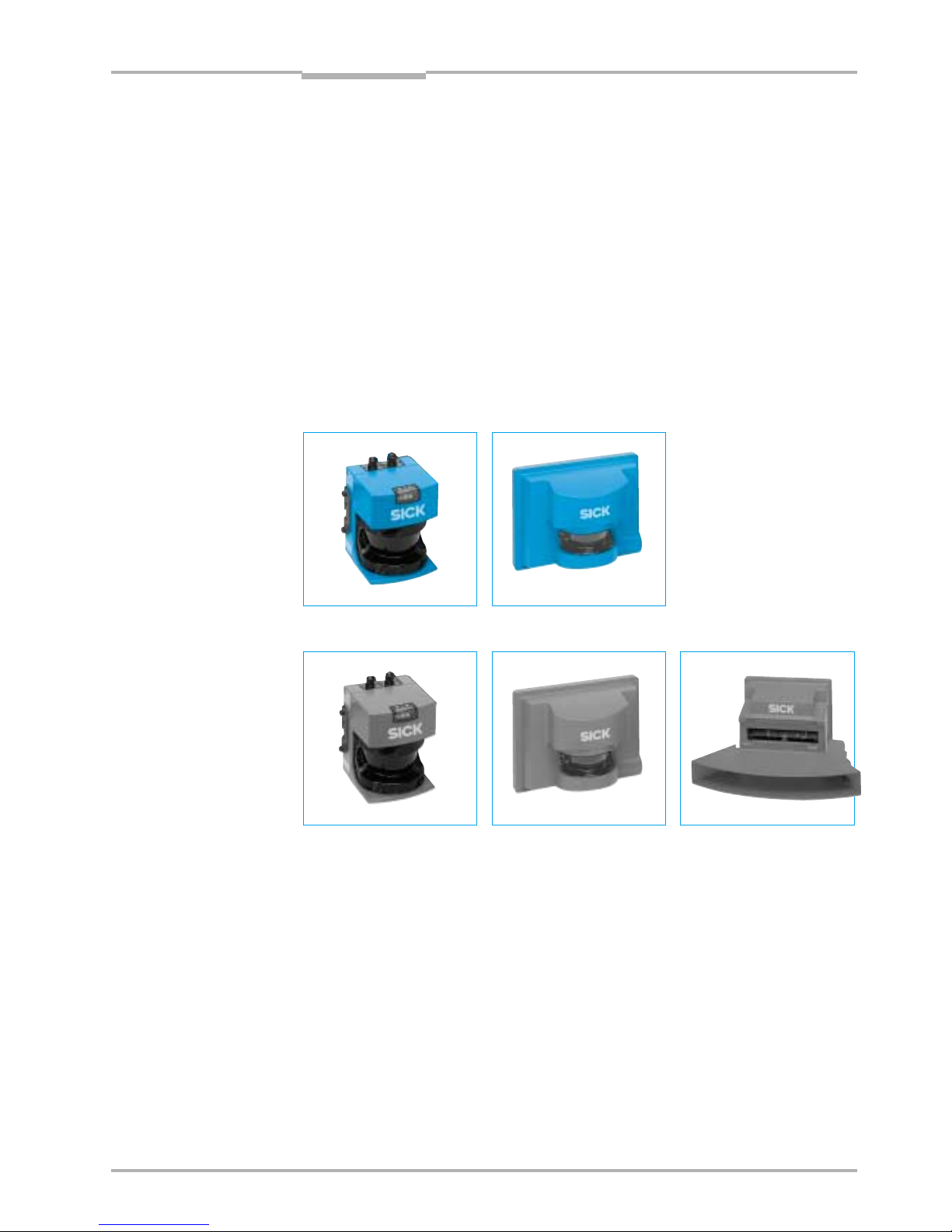
Fig. 2-1: LMS 200
Fig. 2-2: LMS 220
Fig. 2-3: LMS 291
Fig. 2-4: LMS 221
Fig. 2-5: LMS 211
5
See also
12 Overview of
LMS variants
Page 6
Technical Description
LMS 2… Laser Measurement System
Chapter 3
8 008 970/06-2003
2
Operating principle
© SICK AG · Division Auto Ident · Germany · All rights reserved
3 Operating principle
The LMS system operates by measuring the time of flight of laser light pulses: a pulsed
laser beam is emitted and reflected if it meets an object. The reflection is registered by
the scanner’s receiver. The time between transmission and reception of the impulse is
directly proportional to the distance between the scanner and the object (time of flight).
The pulsed laser beam is deflected by an internal rotating mirror so that a fan-shaped
scan is made of the surrounding area (laser radar). The contour of the target object is
determined from the sequence of impulses received. The measurement data is available in real time for further evaluation via a serial interface.
Automatic fog correction is active in the scanner for outdoor use. Raindrops and snowflakes are cut out using pixel-oriented evaluation.
Spot spacing/spot diameter/range
In a radial field of vision, a light impulse (spot) is emitted every 0.25°, 0.5° or 1°
(depending on the variant).
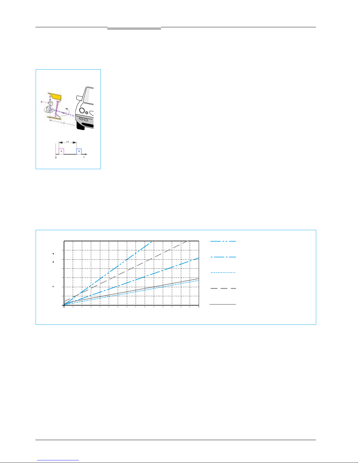
As a result of the beam geometry and the diameter of the individual spots, the spots
overlap on the target object or up to a certain distance. Fig. 3-2 shows spot spacing in
relation to the range and the corresponding spot diameter.
Fig. 3-2: Spot sizes/spot spacing
Fig. 3-1: Operating principle
Spot diameter
LMS 211/221/291
Spot diameter
LMS 200/220
Spot spacing for
angular resolution of 1°
6
Spot spacing for
angular resolution of 0.5°
Spot spacing for
angular resolution of 0.25°
Range [m]
Spot diameter/
spot spacing [cm]
02468101214
0
5
10
15
20
25
30
35
16 18 30
p[]
20 22 24 26 28
Page 7

Technical Description
LMS 2…
Chapter 4
© SICK AG · Division Auto Ident · Germany · All rights reserved8 008 970/06-2003
1
Conditions of use/range
4 Conditions of use/range
4.1 Mounting location
The scanner may be installed in any position. The mounting instructions in Chapter 6 are
to be observed.
100
10
1
0,1
1
10
600
60
Fig. 4-1: LMS 200/LMS 220
Range in relation to object reflectivity
4.2 Heater operation (LMS 220 and LMS 211/LMS 221)
In order to be able to use the LMS at temperature ranges below 0° C, a thermostat-
controlled heater has been installed in these scanners and supplementary front window
heating in the LMS 211. The heating comes into operation at ≤ 10° C order to prevent
thawing within the housing.
Before commissioning the LMS (e.g. before starting work) the interior of the scanner
must be heated to at least 0° C and any ice on the front window must be melted.
The scanner takes approx. 120 min. to heat up at an outdoor temperature of –30° C.
Material Reflectivity
Cardboard, matt black 10%
Cardboard, grey 20%
Wood (raw pine, dirty) 40%
PVC, grey 50%
Paper, matt white 80%
Aluminium, anodised, black 110…150%
Steel, rust-free shiny 120…150%
Steel, very shiny 140…200%
Reflectors > 2000%
4.3 Reflectivity of various objects
The range of the scanner depends on the reflectivity of the target object and the transmission strength of the scanner. Some reflectivity values for well-known materials have
been included below as an overview (KODAK standards).
LMS with high range and fog
correction:
LMS 211-30206
LMS 211-S07
LMS 221-30206
LMS 221-S07
LMS 291-S05
LMS 211-S12/S13/S14
LMS with standard range without fog
correction:
LMS 200-30106
LMS 220-30106
LMS 211-30106
Range [m]
Reflectivity [%]
7
Page 8
Technical Description
LMS 2… Laser Measurement System
Chapter 4
8 008 970/06-2003
2
Conditions of use/range
© SICK AG · Division Auto Ident · Germany · All rights reserved
In exceptional cases, sensitivity can be changed with the user software provided:
• values for standard setting (see diagram): 30 m range/10% reflectivity
• values for less sensitive thresholds: 25 m range/10% reflectivity
• values for more sensitive thresholds: 30 m range/5% reflectivity
Please note:
Note the remission graph in the range 0 to 1,5 m for LMS 211/LMS 221/LMS 291.
Higher sensitivity improves detection capabilities for dark objects, but increases ambient
light sensitivity.
Lower sensitivity reduces detection capabilities for dark objects, but reduces ambient light
sensitivity.
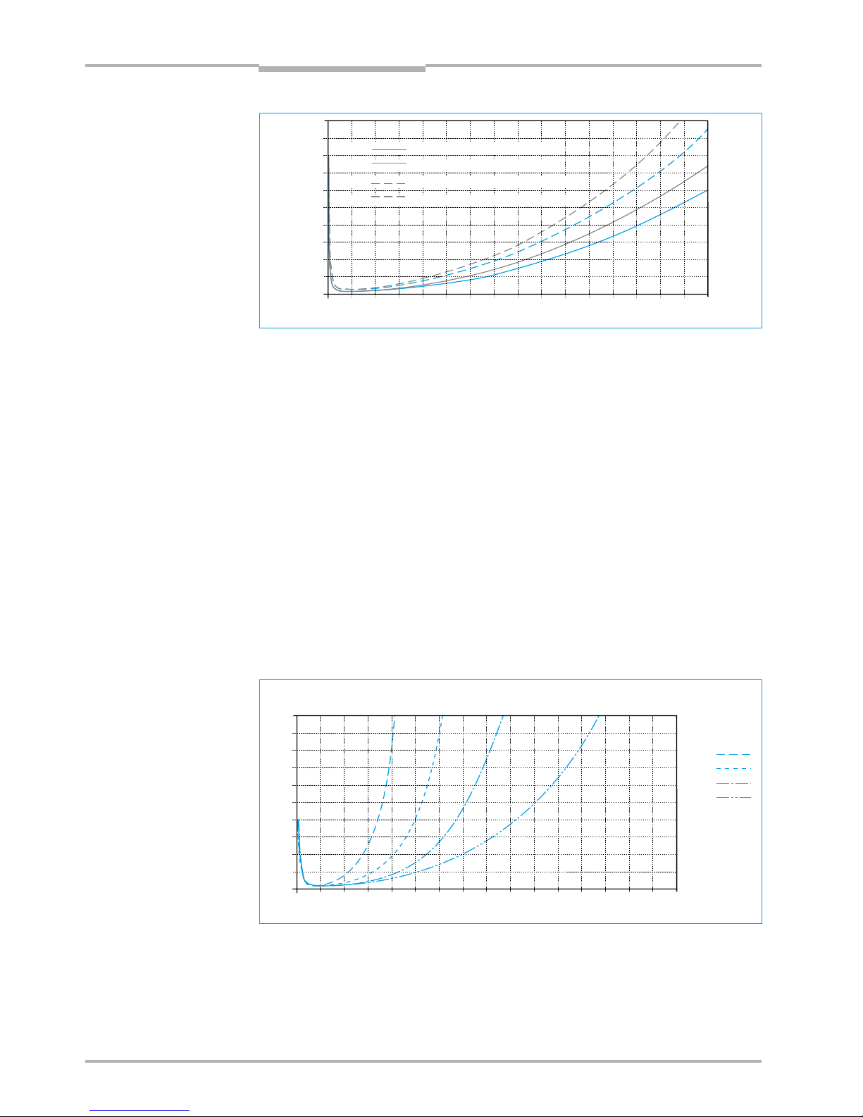
Reflectivity [%]
Range [m]
typ. reflectivity at
nominal visibility
50 m
100 m
200 m
500 m
010
20
30
40
50
60
70
205 15 253035404550
10
0
80
90
100
55 60 65 70 75 80
Fig. 4-3: LMS 211 – relationship between reflectivity and range in fog
Reflectivity [%]
Range [m]
010
20
30
40
50
60
70
205 15 253035404550
10
0
80
90
100
55 60 65 70 75 80
typ. Neugerät mit Verschmutzung (Warnsignal aktiv)LMS 211
LMS 211 typ. new device with clean front window
LMS 221
LMS 291
typ. new device with clean front window
LMS 221
LMS 291
typ. new device with pollution (warning signal active)
typ. new device with pollution (warning signal active)LMS 211
Fig. 4-2: LMS 211, LMS 221, LMS 291, relationship between reflectivity and range with good visibility
4.4 Reflectivity in fog (LMS 211-30206/LMS 221-30206/LMS 291-S05)
Fig. 4-3 to Fig. 4-6 are valid should there be fog during outdoor operation and are to be
observed.
8
Page 9
Technical Description
LMS 2…
Chapter 4
© SICK AG · Division Auto Ident · Germany · All rights reserved8 008 970/06-2003
3
Conditions of use/range
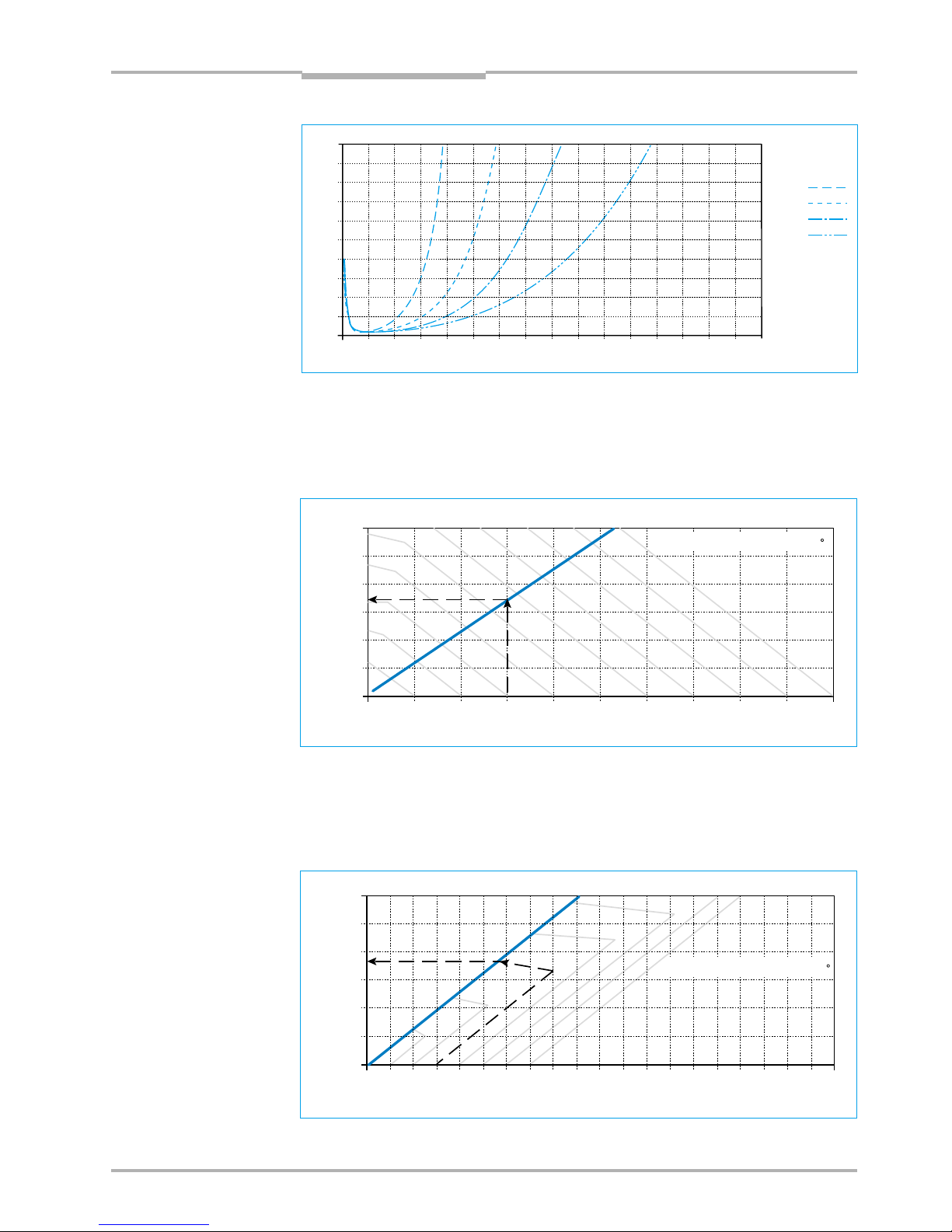
4.5 The „blanking“ curve (LMS Outdoor and LMI 400)
The object suppression software setting is dependent on distance. An object can only be
suppressed up to a certain distance. Furthermore, the scanner switches independently of
object size.
Fig. 4-5: Relationship between the usable range and the defined blanking diameter, e.g.
max. 17 m with the blanking diameter of 0.3 m.
Fig. 4-6: Relationship between the usable range and reliably detected object diameter, e.g. the
LMS switches if it loses the contour in 17 m with a object diameter of 0.3 m.
Reflectivity [%]
Range [m]
typ. reflectivity at
nominal visibility
50 m
100 m
200 m
500 m
010
20
30
40
50
60
70
205 15 253035404550
10
0
80
90
100
55 60 65 70 75 80
Fig. 4-4: LMS 221/LMS 291 – relationship between reflectivity and range in fog
9
4.6 The „contour as reference“ curve (LMS Outdoor and LMI 400)
The contour as reference software setting is dependent on distance. The scanner requires
a minimum contour as reference depending on the distance. Loss of the contour will not be
switched at the switching output if the contour is too small.
0 0.2
10
15
20
25
30
0.40.1 0.3 0.5 0.6 0.7 0.8
5
0
Measurement distance [m]
0.9 1
LMS/LMI 400: angular resolution 1
Suppressible object diameter [m]
0 0.2
10
15
20
25
30
0.40.1 0.3 0.5 0.6 0.7 0.8
5
0
0.9 1.0 1.1 1.2 1.3 1.4 1.5 1.6 1.7 1.8 1.9 2.0
Measurement distance [m]
LMS/LMI 400: angular resolution 1
Reliably detectable object diameters in relation to defined blanking diameter [m]
Page 10

Technical Description
LMS 2… Laser Measurement System
Chapter 5
8 008 970/06-2003
2
Areas of use
© SICK AG · Division Auto Ident · Germany · All rights reserved
5 Areas of use
One distinguishes between three areas of use:
• object measurement
• determining position
• area monitoring
5.1 Object measurement/determining position
Laser scanner measurement data is used for object measurement and determining
position. These measurement data correspond to the surrounding contour scanned by
the device and are given out in binary format via the RS 232/RS 422 interface.
The telegram listing required is supplied with the device.
Our MST Measurement Software Tool provides further support for software connections
to the LMS laser scanner (please see separate Technical Description, order no.
8008464).
Processing measurement data
Processing measurement data allows individual adaptation to the system’s particular
measurement task.
Possible data preparation within the LMS:
• Average value formation from 2 - 250 scans
• Limiting the sector from which values are transferred (e.g. beams 10 - 30) for data
reduction
Possible external data processing:
• Evaluation of partial sectors of the 100° or 180° field of view
• Averaging of the measurement values transferred (increasing accuracy and smooth-
ness)
• Straight line and curve approximations by interpolation of measurement values
• Determination of position/volume of any objects
• 3rd dimension provided by shaft encoder, etc. (length information/speed of transport)
External evaluation (software) can take place at a PC or SPC.
Fundamentally, the distance value per individual impulse (spot) is evaluated. This means
that a distance value is provided every 0.25°, 0.5° or 1°, depending on the angular reso-
lution of the scanner.
Angular resolution 0.25° 0.25° 0.5° 1°
max. scanning angle *) 100°/180° 180° 100°/180° 100°/180°
max. no of measured
values 401 721 361 181
4x1°-values,
interlaced
*)symmetrical, from the middle
Angular resolution is set using a software telegram.
10
Page 11
Technical Description
LMS 2…
Chapter 5
© SICK AG · Division Auto Ident · Germany · All rights reserved8 008 970/06-2003
3
Areas of use
As the individual values are given out in sequence (beginning with value 1), particular angular positions can be allocated on the basis of the values’ positions in the data string.
Note that the LMS turns towards the left (see Figs. 5-1 and 5.2).
In its default state the scanner is set to the “Measured values on request” mode and
“Transfer rate 9,600 baud” (changes can be made using the appropriate telegram commands).
It is recommended that the scanner is operated in the “9,600 baud on Power-on” mode
(default setting). Conversion to a different baud rate can take place after the complete
system has been started up.
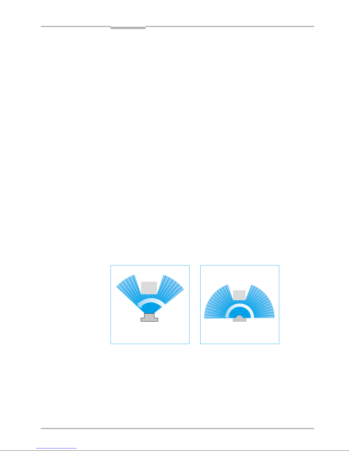
Fig. 5-1: Direction of transmission for
LMS 211 scanners
5.2 Area monitoring/Detection
Here, the system is responsible for automatically reporting that an area „is free“. This
means that an infringement of a field, e.g. by an object or machine part, leads to a switching signal at an output.
Pixel-oriented evaluation/object blanking
Pixel-oriented evaluation is used for suppressing raindrops and snowflakes or other particles, and thus makes the system less sensitive to environmental factors. This involves
saving the sequential messages (measured values) from each individual spot in each
scan, and a separate counter being started for each spot. Erroneous measurements can
be filtered out by repeatedly examining the reported spot (multiple scanning whose
number depends on the setting selected).
Pixel-oriented evaluation should be included in the corresponding evaluation software
when external data processing is undertaken.
Object blanking is used for suppressing an object that is not to be detected, e.g. a steel
cable, that is located within the monitored field.
Fig.5-2: Direction of transmission for
LMS 200, LMS 220, LMS 221,
LMS 291 scanners
last value
first value
last value
first value
11
scanning angle 100°
scanning angle 180°
Page 12
Technical Description
LMS 2… Laser Measurement System
Chapter 6
8 008 970/06-2003
2
Mounting
© SICK AG · Division Auto Ident · Germany · All rights reserved
6 Mounting
Mounting sets (see Fig. 6-1) are available for easy installation. They allow adjustment of
devices in both axes, as shown.
The scanner can be installed in any position, though direct sunlight on the front window
is to be avoided (to prevent dazzle).
Outdoor variants should generally be mounted in such a way that the connection plug is
located on the lower right-hand side of the back plate in order not to affect pollution
measurement (exit window).
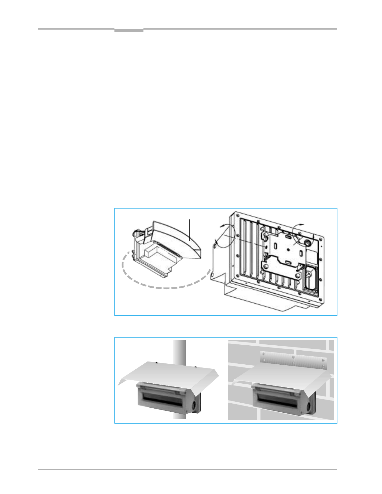
Outdoor installation:
An appropriate sunshade is to be provided to prevent direct sunlight falling on the scanner housing (sheet metal, etc, see Fig. 6-2). Threaded holes are provided on the rear of
the scanner for attachment (LMS 211/221/220). A dust prevention shield is recommended for preventing dust and/or condensation on the front window (see LMS 211).
Purging air can be used if dust is present in large quantities. The cap of the optional connection socket (motor flap) must be screwed in (to maintain the enclosure rating).
Fig. 6-1: Mounting set for LMS 220/LMS 211/LMS 221
Fig. 6-2: Sunshade (examples)
±7, 5 °
±7, 5 °
12
LMS 211 dust shield
Page 13

Technicall Description
LMS 2…
Chapter 6
© SICK AG · Division Auto Ident · Germany · All rights reserved8 008 970/06-2003
3
Mounting
Fig. 6-3: Attachment set for mast mounting of LMS 220/LMS 211/LMS 221
Fig. 6-4: Mounting set for LMS 200/LMS 291
13
Fig. 6-5: Weather protection for LMS 220/LMS 221
Page 14

Technical Description
Laser Measurement System LMS 2…
Chapter 7
8 008 970/06-2003
2
© SICK AG · Division Auto Ident · Germany · All rights reserved
LMS 211/220/221 electrical installation
7 LMS 211/LMS 220/LMS 221 electrical installation
The scanners’ operating voltage is 24 V DC ± 15%.
7.1 Data interface
The data interface of the scanners is for setting parameters using a PC and for data exchange on external software evaluation (e.g. with SICK’s LMI Laser Measurement Interface).
The interface type may be selected as RS 232 or RS 422 by bridging in the connection plug.
A prepared service cable is available for setting parameters (see 14: Order numbers).
Please note:
A shielded cable with “twisted pair” wires (2x2 TP, see 14: Order numbers) is required for
operation with external data evaluation in real time.
7.2 Power supply
The electronics of the scanners is fed directly from a stabilised 24 V DC mains adapter.
The LMS 211/LMS 220/LMS 221 scanner heater is regulated internally by a thermostat.
An unregulated 24 V DC mains adapter is sufficient for power supply for the heater (current
uptake of active heater is approx. 5 A). In the LMS 211/LMS 221, separate connection terminals are available in the connection plug for the scanner heater/motor flap. By using separate wiring it is possible to keep the heater in operation even when the scanner is switched
off for longer periods – in order to maintain the operating temperature at a suitable level
until the scanner is switched back on (prevents subsequent thawing within the scanner).
Fig. 7-1: Wiring for stand-alone operation (switching applications)
Fig. 7-2: Wiring with external data processing
2
LMS
control cabinet
switching outputs
sensor
heater
DC 24 V
=
≈
3
2
DC 24 V
=
≈
LMS
3
2
or
switching outputs
sensor
heater
2
LMS
2
2
2x2 TP
LMS
control cabinet
control
system
RS 422
sensorheater
(motorflap)
evaluation
host
computer/
PC
DC 24 V
=
≈
or
DC 24 V
=
≈
RS 422
sensorheater
(motorflap)
14
Page 15

Technical Description
LMS 2…
Chapter 7
© SICK AG · Division Auto Ident · Germany · All rights reserved8 008 970/06-2003
3
LMS 211/220/221 electrical installation
Please note:
Observe acceptable voltage drops through the cable. The entire heating capacity (re-
quired at temperatures below –10°C) is only available with at least 24 V rated voltage
(see 13 Technical data). The voltage drop through cables at a current flow of 5 A is
0.114 V/m with a cable cross-section of 1.5 mm2 and 0.075 V/m with a cross-section
of 2.5 mm
2
.
7.3 Motor flap for the LMS 211-S12
The optional motor flap in the dust prevention shield is connected directly to the LMS
using the prepared plug (socket at the rear of the housing).
The LMS heater power supply must be connected to operate the motor flap. Configuration takes place using the LMI user software, by separate data telegram to the LMS, or
with a 24 V DC control voltage on pin 5 of the connection plug (see also Fig. 7-4).
If the motor flap is not in use, or is no longer in use, the connection socket must be covered with the cap (to maintain the enclosure rating).
Fig. 7-3: Wiring in conjunction with LMI
2
2
2x2 TP
LMS
control cabinet
switching
outputs
RS 422
sensor
heater
(motorflap)
DC 24 V
=
≈
LMI
DC 24 V
RS 422
2
15
Page 16

Technical Description
Laser Measurement System LMS 2…
Chapter 7
8 008 970/06-2003
4
© SICK AG · Division Auto Ident · Germany · All rights reserved
LMS 211/220/221 electrical installation
Fig. 7-5: Service cable for setting parameters
(prepared as RS 232 for PC, can also be used
for RS 422 with jumper between terminals 3-11)
Fig. 7-4: LMS connection plug/interface wiring terminal allocation
Fig. 7-6: LMS 211/LMS 221/LMS 220 wiring
7.4 LMS 211/LMS 220/LMS 221 electrical connection
TxD+
RxD+
(10)
(2)
GND
RxD
TxD
(2)
(3)
GND
(5)
PC or
evaluation
LMS
RxD–
RxD+
(1) TxD–
TxD+
PC/LMI
evaluation
LMS
TxD–
(2)
(9) RxD–
TxD+(10) RxD+
(3)
(11)
screen
Wiring the RS 232 interface
Wiring the RS 422
RxD–
RxD+
1 TxD–
TxD+
RS 232/RS 422
1)
2
3
4
heater 24 V/5 A,
motor flap
OUT A
OUT B
restart
scanner 24 V/1 A
5
6
7
8
9
10
11
12
13
14
15
16
heater, motor flap
GND
FC
2)
x
Weak/Out C
scanner GND
data cable reference earth
(screen)
RS 232/RS 422
1)
x = reserved, not wired
heater, motor flap
Please note: provide current limitation
(e.g. fuse) for external power supply
LMS
16
+
–
RxD–1RxD+2TxD+10TxD–
9
3 11
FC5Out A13Out B14Out C7Res1524V
16
8 12 4
GND 24V GND
+24V
restartswitching outputs
scanner heater
+24V
FC
external
interface type
jumper: RS 422
without jumper:
RS 232
RS 232
RS 422
screen
without jumper RS 232, with jumper RS 422
Control of motor flap
Either internally controlled (data telegram or
configuration via user software) or externally
via 24 V DC control voltage at terminal 5
(FC = Flap Control)
Internal control
Jumper from OUT A to FC (terminals 5–13)
OUT A provides the control voltage here,
function can be defined via software
External control
Wire terminal 5 (Flap Control) with 24 V DC
external control voltage
24 V = flap open
0 V = flap closed
U
control
= 24…48 V DC
I ≤ 30 mA
1)
2)
Page 17

Technical Description
LMS 2…
Chapter 7
© SICK AG · Division Auto Ident · Germany · All rights reserved8 008 970/06-2003
5
LMS 211/220/221 electrical installation
17
Fig. 7-8: Connection diagram of LMS 211/LMS 221 with relay outputs
7.5 Electrical connection LMS 211/LMS 221 with relay outputs
Fig. 7-7: Layout of the connection plug
Note:
Motor flap on LMS with relay outputs not applicable.
Factory setting of relay outputs Normally Open N.O.:
LMS-field clear = contact closed
Behaviour of the switching outputs
All LMS types are designed in such way, that the switching outputs are active (24 Vlevel) if the corresponding monitored field is clear. If, however, a field is infringement the
relevant output switches to 0 V-level. The contacts of LMS units with relay output on
OUT A and OUT B are set to N.O. function. The corresponding contact is closed when
the monitoring field is clear and opens if there is a field infringement.
This functionality of the switching outputs means, that the connecting cables are automatically monitored for any breaks.
Output OUT C is designed to act as a regular field output but automatically assumes an
error signalling function if there is a break (see also Chap. 8.3.3).
RxD–
RxD+
1 TxD–
TxD+
RS 232/RS 422
1)
2
3
4
Heating 24 V/5 A
OUT B.2
OUT B.1
Restart
Scanner 24 V/1 A
5
6
7
8
9
10
11
12
13
14
15
16
Heating GND
OUT A.1
OUT A.2
Weak/OUT C
Scanner GND
Ground reference
data cable
(shield)
without jumper RS 232, with jumper RS 422
1)
RS 232/RS 422
1)
RxD–1RxD+2TxD+10TxD–
9 3 11 5
Out A
13
Out B14Out C7Res1524V
16 8 12 4
GND 24V GND
+24V
Restart
Relay outputs
Sensor Heating
Interface type:
jumper: RS 422
no jumper:
RS 232
RS 232
RS 422
Shield
6
Weak
ab
Page 18

Technical Description
LMS 2… Laser Measurement System
Chapter 8
8 008 970/06-2003
2
LMS 200/LMS 291 electrical installation
© SICK AG · Division Auto Ident · Germany · All rights reserved
8 Electrical connection LMS 200/LMS 291
8.1 Electrical connection
Scanners require an operating voltage of 24 V DC ± 15% with a power consumption of
≤ 20 W plus the load on the three possible outputs OUT A (max. 250 mA), OUT B (max.
250 mA) and OUT C (max. 100 mA).
The restart input can be allocated as restart or for changing field (see LMS/LMI User
Software Operating Instructions for details).
Power is supplied to the devices using a plug-in connection box with a high enclosure
rating (see Fig. 8-2), while interface connection takes place through another connection
box (RS 232 or RS 422).
Fig. 8-1: LMS 200/LMS 291 components and typical set-up
Fig. 8-2: Scanner with plug-in connection boxes
8.2 Interface plugs (plug modules)
The interface plugs are built into plug modules. Only when attachment of the plug
modules to the sensor has been completed
does the device correspond to the IP 65
design and EMC requirements (ESD) according to CE.
Furthermore, please note that regarding
ESD protection the LMS should only be
operated with the plug modules mounted.
interface plug
power supply plug
cable connection
possible from above
and from rear
1. Scanner
2. Plug module with interface cables to
evaluation unit (e.g. switching cabinet, SPC, PC, etc.) or interface cable
for temporary connection to PC for
configuration and servicing of the
device
3. Connection cable for power supply
and switching cables to a machine or
a switching cabinet
4. PC for configuration and servicing
5. 3.5" diskette with LMS User Software
1
2
3
4
5
2
18
Page 19

Technical Description
LMS 2…
Chapter 8
© SICK AG · Division Auto Ident · Germany · All rights reserved8 008 970/06-2003
3
LMS 200/LMS 291 electrical installation
Fig. 8-4: Interface plug
8.3 LMS 200/LMS 291 electrical connection
8.3.1 RS 232/RS 422 conversion
The prepared interface plug is converted to an RS 422 form using a standard bridge.
The interface plug reverts to the RS 232 form on removal of the bridge.
Please note:
Bridging may only be carried out within the plug module.
Fig. 8-3: LMS 200/LMS 291 power supply plug
Fig. 8-5: Convertible interface plug (RS 422 pre-selected)
jumper
soldered
soldered
Please note: Provide current limitation (e.g. fuse) for external power supply
PIN Signal designation Input/
RS 232 RS 422 output
1 NC RxD– –
2 RxD RxD+ E
3 TxD TxD+ A
4 NC TxD– –
5GND GND –
6NC NC –
7 NC jumpered –
8 NC RS 422 _
9NC NC –
PIN Signal designation Input/
output Wire colour
1 GND_EXT (earth) – brown
2 Restart E blue
3 VCC_EXT (24 V DC ± 15%) red
4NC –
5 OUT C/weak signal A grey
6NC –
7NC –
8 OUT B A turquoise
9 OUT A A orange
19
1 GND_EXT
2 Restart
3 VCC_EXT
(24 V DC ± 15%)
4NC
5 OUT C/Weak
6NC
7NC
8 OUT B
9 OUT A
Imax=250 mA
1
5
6
9
Ltg.Ø 4…8 mm 6x 0,5 mm
2
Page 20

Technical Description
LMS 2… Laser Measurement System
Chapter 8
8 008 970/06-2003
4
LMS 200/LMS 291 electrical installation
© SICK AG · Division Auto Ident · Germany · All rights reserved
8.3.2 Cable entry in plug module
Cables can enter the plug module from above or from the rear.
Please note:
In order to ensure that the scanner is sufficiently sealed (IP 65), the LMS must always be
provided with plug modules – even if the interface is not in use. The plug modules must be
provided with breech screws or PG cable glands with seals and SUB-D device plugs.
Fig. 8-6: Plug module structure
20
8.3.3 Functions of the indicator lights
State of system LED LED LED Indication LED yellow Error signal
green yellow red static frequency (OUT C)
Initialising (start) 0 1 1 •
OK, all fields clear 1 0 0 •
Field infringed (A, B, C) 0 0 1 •
Download 1 1 0 •
Restard requested; 0 1 1 •
Restard timed (Field A)
Contamination- 1 1 Hz
Warning 50% on/50% off
Contamination- 0 1 1 1 Hz 1 Hz
Error 90% on/10% off 90% on/10% off
Error 0 1 1 1 Hz 1 Hz
10% on/90% off 10% on/90% off
Fatal Error 0 1 1 1 Hz 1 Hz
50% on/50% off 50% on/50% off
Switching signal on OUT C alternatively as field output or error signal (higher priority)
Tab. 8-1: Functions of the indicator lights
Fig. 8-7: The indicator lights on LMS 200/LMS 291
rot
gelb
grün
red
yellow
green
Page 21

Technical Description
LMS 2…
Chapter 9
© SICK AG · Division Auto Ident · Germany · All rights reserved8 008 970/06-2003
1
Synchronisation of two laser scanners
9 Synchronisation of two laser scanners
If two LMS units are operated in close vicinity to each other, e.g. for measuring packages, there may be mutual interferences under certain circumstances. In order to prevent this the rotating mirrors of the two LMS units can be synchronised. The mirrors are
then maintained in a position displaced by 180° relative to each other.
In the process one LMS is defined as the MASTER, the other the SLAVE.
9.1 Pre-conditions for synchronisation
Scanners are capable of synchronisation from software version 02.03 and above and
hardware class serial no. 9919... and above.
The scanners are wired according to the wiring plan Fig. 9-1 below.
Fig. 9-1: Connection diagram synchronisation
9.2 Procedure
• Wire scanners with power supply cables from the connection set
• The maximum length of each of the supply cables should not exceed 5 m
• Both scanners must be supplied from a common mains adapter
• The separation of the power supply for the two scanners must first take place in the con-
nection box (see 14 Order numbers)
• The MASTER output OUT C is connected to the SLAVE RESTART
• Wire a pull-down resistance of 470 Ω/2 W to GND_EXT (supplied with the connection
box). The linkage takes place in the connection box.
The remaining scanner outputs can be led from the connection box to the switching cabinet
without any further measures being taken.
The scanner data cables must not be wired through the connection box. Observe instructions in the Technical Description when selecting the type of interface and acceptable cable
lengths.
21
Page 22

Technical Description
LMS 2… Laser Measurement System
Chapter 9
8 008 970/06-2003
2
Synchronisation of two laser scanners
© SICK AG · Division Auto Ident · Germany · All rights reserved
9.3 Commissioning synchronisation
Reaction of the scanners on power-on
• The MASTER gives out its synchronisation pulse immediately after configuration has
taken place
• The SLAVE independently synchronises itself after RESET or POWER ON
Synchronisation behaviour of the SLAVE
Possible states after RESET during the synchronisation phase
SLAVE (LEDs) red yellow green approx.
duration
1 Waiting for synchronisation signal 100% 50% 0.5 Hz 0% max. 45 s
from MASTER
2 Synchronisation phase 100% 100% 100%
(adaption of the number of rotations)
3 Synchronisation adjusted to 100% 0% 100% appr. 4 s
pre-defined phase state
4 Synchronisation completed 100% 100% 0% *)
5 Scanner operating state OK 0% 0% 100%
Error 100% 0% 0% *)
*) If the synchronisation process has not been completed after 100 seconds the process is aborted
and an error displayed.
The LED indicators of the MASTER act as in standard mode (see Chapt. 8.3.3).
After synchronisation has taken place in the initialisation phase, the synchronisation status
is cyclically controlled and monitored. On loss of synchronisation for a period longer than
10 seconds and shorter than 30 seconds an info is entered in the SLAVE error log.
On loss of synchronisation for a period longer than 30 seconds an error is entered in the
SLAVE error log.
If the SLAVE is able to synchronise itself again, the error entry is deleted or saved as a
non-current error.
In synchronisation mode the MASTER suffers just one restriction, namely that output
OUT C cannot be used for the field monitoring function.
Please note:
The connection box corresponds to enclosure rating IP 65, but IP 54 on use of the PG 11
and PG 16 screw joints. If enclosure rating IP 65 is required, the appropriate PG screw
joints are to be used (Tradeware).
22
Fig. 9-2: View into connection box for synchronisation
130
94
57
1112
12
3134145156167178189
191020
Page 23

Technical Description
LMS 2…
Chapter 10
© SICK AG · Division Auto Ident · Germany · All rights reserved8 008 970/06-2003
1
Heating plate
10 Heating plate for the LMS 200/LMS 291
A supplementary heating plate is required if scanners with IP 65 housings are operated
below 0° C.
The heating plate is mounted between the back plate of the scanner and the standard
mounting set.
The temperature of the heating plate is controlled internally by a thermostat.
Attention should be paid to ensure that the heating plate lies level on the scanner rear
and that the transfer of warmth is not hindered.
The connection terminals for the power supply are below the cover. Conventional cables
can be used for connection.
The device is to be safeguarded with an FI safety switch.
Technical data (electrical)
Power supply 230 V AC ± 10%
Power uptake 30 W (cyclic, thermostat-controlled)
Peak current on power on < 2.5 A
Supply line cable entry PG 9
Supply line wire cross-sections up to 1.5 mm
2
Technical data (mechanical)
Protection category IP 65
Operating temperature –12…+50 °C
Heating-up time at –12 °C max. 20 min.
Storage temperature –20…+70 °C
Dimensions see Fig. 10-1
Weight approx. 1.2 kg
Table 10-1: Heating plate technical data
23
Page 24

Technical Description
LMS 2… Laser Measurement System
Chapter 10
8 008 970/06-2003
2
© SICK AG · Division Auto Ident · Germany · All rights reserved
Heating plate
Fig. 10-1: Mounting the heating plate on the LMS 200/LMS 291
24
ATTENTION! Safety
cable must be
connected.
Connection of the heating plate
Connection cable
4 M6 x 30 screws
Mounting set 1
SICK order no.:
2015623
4 M8 x 15 screws
Installation of LMS with heating plate:
terminal compartment either pointing up or down.
Cable exit 1 x PG9
Cover with PG9 mountable on the left or right.
Heating plate protection category IP 65
Use 30 mA FI safety switch
connection cable
(shown without terminal
compartment cover with PG9
cable gland)
Page 25

Technical Description
LMS 2…
Chapter 10
© SICK AG · Division Auto Ident · Germany · All rights reserved8 008 970/06-2003
3
Heating plate
25
Fig. 10-2: Dimensions of weather protection for LMS 220/LMS 221
Weather protection
242
381,5
69
57 65
25°
11,5°
64,3
268,5
200
34,25
246,5
400
450
650
380
101,7
292
113
76
40
R82,5
R325
290
ø40
ø40
292
101,7
113
76
40
290
380
Page 26

Technical Description
LMS 2… Laser Measurement System
Chapter 11
8 008 970/06-2003
2
© SICK AG · Division Auto Ident · Germany · All rights reserved
Dimensional drawings
11 Dimensional drawings
Fig. 11-1: LMS 211 dimensions
26
space required for plug
approx. 65
3 x PG11 for cable
Ø 5…12 mm
M8 - 9 deep (4x)
M5 - 10 deep (8x) for
mounting a sunshade
sheet or something
similar. Not to be used
for mounting device.
centre of rotating
mirror wheel
centre of
light exit
Replaceable
drying agent
cartridge
352
351,5
111
Page 27

Technical Description
LMS 2…
Chapter 11
© SICK AG · Division Auto Ident · Germany · All rights reserved8 008 970/06-2003
3
Dimensional drawings
Fig. 11-2: LMS 211 dimensions with dust prevention shield
27
space required for plug
approx. 65
M8 - 9 deep (4x)
M5 - 10 deep (8x) for
mounting a sunshade
sheet or something
similar. Not to be used
for mounting device.
centre of
light exit
Replaceable
drying agent
cartridge
3 x PG11 for cable
Ø 5…12 mm
Dust prevention shield
can be swung upwards
to clean front window
centre
of rotating
mirror wheel
111
125
125
LMS 211 - S12
only
LMS 211 - S12
only
LMS 211-S12 with motorflap connectable
Page 28

Technical Description
LMS 2… Laser Measurement System
Chapter 11
8 008 970/06-2003
4
© SICK AG · Division Auto Ident · Germany · All rights reserved
Dimensional drawings
28
Fig. 11-3: LMS 220/LMS 221 dimensions
space required for plug
approx. 65
M8 - 9 deep (4x)
M5 - 10 deep (8x) for
mounting a sunshade
sheet or something
similar. Not to be used
for mounting device.
3 x PG11 for cable
Ø 5…12 mm
Replaceable
drying agent
cartridge
centre
of rotating
mirror
wheel
centre of
light exit
111
Page 29

Technical Description
LMS 2…
Chapter 11
© SICK AG · Division Auto Ident · Germany · All rights reserved8 008 970/06-2003
5
Dimensional drawings
Fig. 11-4: LMS 200/LMS 291 dimensions
29
plug-in area approx. 265
centre of
mirror wheel
centre of
light exit
93
Page 30

Technical Description
LMS 2… Laser Measurement System
Chapter 11
8 008 970/06-2003
6
© SICK AG · Division Auto Ident · Germany · All rights reserved
Dimensional drawings
Fig. 11-5: Mounting sets 1, 2, and 3 dimensions
30
for M6 countersunk
screws countersinking
DIN 74-Am6
Mounting set 1
Mounting set 1+ 2
Mounting set 1+2
Mounting set 1+2+3
183
66,6
Page 31

Technical Description
LMS 2…
Chapter 11
© SICK AG · Division Auto Ident · Germany · All rights reserved8 008 970/06-2003
7
Dimensional drawings
Fig. 11-6: LMS 211/LMS 221/LMS 220 mounting set
31
160,4
100
9,5
51
35
Mitte optische Achse
14
100
155
± 7,5°
± 7,5°
centre of optical axis
Page 32

Technical Description
LMS 2… Laser Measurement System
Chapter 11
8 008 970/06-2003
8
© SICK AG · Division Auto Ident · Germany · All rights reserved
Dimensional drawings
Fig. 11-7: LMS 200 fine adjustment mounting set
32
weight without 3rd axis 4,8 kg, with 3rd axis 6,3 kg
Mounting dimensions
Installation Use
3rd axis available as
order number
2020926
Mounting on profiles (types 80x80):
4x sliding block 8StM6, heavy
4x screws
4x washers
(not included in delivery)
without 3rd axis
with 3rd axis
40
Page 33

Technical Description
LMS 2…
Chapter 12
© SICK AG · Division Auto Ident · Germany · All rights reserved8 008 970/06-2003
1
Overview of LMS variants
12 Overview of LMS variants
LMS type Scanning Resolution/typ. meas- Typ. range with Heating Fog Relay
angle urement accuracy 10% reflectivity correction
Table 12-2: Overview of scanner functions
33
Function LMS performance Remarks Default settings,
characteristics delivery condition
Monitored fields, static • rectangular dynamic fields possible A, B, C segmented,
• segmented (and teach-in) via LMI 400 each 50 mm radial (indoor)
each 5 cm radial (outdoor)
Number of field sets 2 expansion to 4 field 2
sets with LMI 400
Switching field sets external button or contact further logical linkages
or telegram possible via LMI 400
Switching outputs 24 V DC 3 further 6 with LMI
Switching outputs LMS 211/221
alternative with relay contacts 2 — normally open
Subtractive fields yes monitored areas
= field A minus field B
Field evaluation • scan-oriented pixel-oriented
(blanking possible) no blanking
• pixel-oriented 2 scans multiple reading
(no blanking)
• contour as reference
Restart after field infringement • direct restart external button for direct,
• restart after defined delay switching field set without time delay
• restart interlock or restart
Temporary field set yes field defined via external
software (online)
Measured value transfer
in real-time (500 kBd) yes
Selectable baud rate: 9.6 kBd, 500 kBd required for 9.6 kBd
19.2 kBd, 38.4 kBd, 500 kBd yes real-time transfer parity: none
Measurement range in mm up to 8 m/16 m/32 m range selectable mm, indoor-LMS
Measurement range in cm up to 80 m cm, outdoor-LMS
Conversion of polar co-ordinates max. 200 measured polar co-ordinates
into Cartesian co-ordinates yes values as Cartesian
co-ordinates
Measured value flags • infringement of field A, B, C data output supple- fields A, B; dazzle
or mentary information,
• detection of reflector e.g. for navigation
or using reflector marks
• dazzle, field A, B
Minimum perpendicular distance yes measured values for fields A, B, C
Measured value output • all measured values of a scan
• averaged measured values (up to 250 scans) measured values on request
• measured values for partitioned sector
• averaged measured values for partitioned sector (up to 250 scans)
Table 12-1: Overview of LMS variants
Scanner functions
LMS 291-S05 180° 10 mm/± 35 mm 30 m – ✓ –
LMS 200-30106 180° 10 mm/± 15 mm 10 m – – –
LMS 221-30206 180° 10 mm/± 35 mm 30 m ✓✓ –
LMS 211-30206 100° 10 mm/± 35 mm 30 m ✓✓ –
LMS 211-S07 100 ° 10 mm/± 35 mm 30 m ✓ ✓ ✓
LMS 221-S07 180° 10 mm/± 35 mm 30 m ✓✓ ✓
LMS 220-30106 180° 10 mm/± 15 mm 10 m ✓ – –
LMS 211-30106 100° 10 mm/± 15 mm 10 m ✓ – –
Page 34

Technical Description
LMS 2…
Chapter 13
© SICK AG · Division Auto Ident · Germany · All rights reserved 8 008 970/06 -2003
2
Technical data
13 Technical data
General
Range max. 80 m (see Chapter 4)
Angular resolution 0.25°1)/0.5°/1° (selectable)
Response time 53 ms/26 ms/13 ms
Measurement resolution 10 mm
System error LMS 200-30106/ LMS 211/LMS 291/
(environmental conditions: LMS 220-30106 LMS 221-30206
good visibility, Ta=23°C, LMS 211-30106
reflectivity 10%…10,000%) typ. ± 15 mm typ. ± 35 mm
(mm-mode), range 1…8 m (mm-mode), range 1…20 m
typ. ± 4 cm typ. ± 5 cm
(cm-mode), range 1…20 m (cm-mode), range 1…20 m
Statistical error typ. 5 mm (mm-mode) typ. 10 mm (mm-mode)
standard deviation (at range ≤ 8 m/ (at range 1…20 m/
(1 sigma) ≥ 10 % reflectivity/≤ 5 kLux) ≥ 10 % reflectivity/≤ 5 kLux)
Electrical
Data interface RS 232/RS 422 (configurable)
Transfer rate 9.6/19.2/38.4/500 kbaud
Switching outputs, standard variants 3xPNP; typ. 24 V DC
OUT A, OUT B max. 250 mA, OUT C max. 100 mA
Switching outputs, relay variants OUT A, OUT B (relay) max. switching voltage 48 V DC/26 VAC
(protected low voltage, safe isolation from mains)
max. switching current 0,7 A; max. switching power 30 W
OUT C/weak (PNP) typ. 24 V DC, max. 100 mA
Supply voltage 24 V DC ± 15% (max. 500 mV ripple)
(scanner-electronics) current requirement max. 1,8 A (incl. output load)
Supply voltage 24 V DC (max. 6 V ripple)
(heating, LMS 211/220/221 only) current requirement max. 6 A (cyclic)
Power consumption approx. 20 W (without output load) plus heating with
approx. 140 W
Electrical protection class safety insulated, protection class 2
Laser protection class 1 (eye-safe)
Interference resistance acc. to IEC 801, part 2-4; EN 50081-1/50082-2
Operating ambient temperature 0…+50 °C –30…+50 °C (warming-up time
(LMS 291 also) approx. 120 min.at T
min
),
LMS 220/211-30106
Storage temperature –30…+70 °C
Mechanical LMS 200-30106/LMS 291-S05 LMS 211/220/221
Enclosure rating IP 65 IP 65 and IP 67
Weight approx. 4.5 kg approx. 9 kg
Dimensions see Chapter 11 Dimensional drawings
Vibration fatigue limit acc. to IEC 68 part 2-6, table 2c, frequency range
10…150 Hz, amplitude 0.35 mm or 5 g single impact
IEC 68 part 2-27, table 2, 15 g/11 ms
permanent vibration IEC 68 part 2-29, 10 g/16 ms
Shock absorbers are recommended for heavy
vibration and impact demands (e.g. AGV applications).
Table 13-1: Technical data
34
Definition
measuring accuracy
Resolution
The resolution of a measuring
device is the smallest possible
distance different from zero
between two consecutive individual measurement values.
The resolution can be reduced
by using averaged values.
Systematic error
Systematic error is the sum of
all the deviations over a
defined excent of range and
reflectivity, which cannot be
reduced even using averaged
values.
Standard deviation
The standard deviation is
calculated using at least 100
measurement values of a
target with a certain reflectivity
at a certain distance with a
certain amount of illumination.
1)
Angular resolution 0.25° not
possible in the monitoring
fields mode.
Page 35

Technical Description
LMS 2…
Chapter 14
© SICK AG · Division Auto Ident · Germany · All rights reserved8 008 970/06-2003
1
Order numbers
14 Order numbers
Laser scanners, indoor Order no.
LMS 200-30106 1015850
LMS 220-30106 1015945
LMS 211-30106 1025629
Laser scanners, outdoor Order no.
LMS 211-30206 1018023
LMS 221-30206 1018022
LMS 291-S05 1018028
LMS 291-S14 1025329
LMS 211-S07 (relay outputs) 1018966
LMS 221-S07 (relay outputs) 1018965
LMS 211-S14 1025487
LMS 211-S13 1021214
LMS 211-S12 1023952
LMS 211-S14 1025328
Laser scanners (housing not lacquered) Order no.
LMS 209-S02 (technical data as LMS 200) 1016414
LMS 200/LMS 291 accessories
Mounting set 1 2015623
Mounting set 2 2015624
Mounting set 3 2015625
Fine adjustment mounting set 2002925
3rd axis for fine adjustment 2020926
Connection set 1, power supply and interface plugs (without cables) 2018963
Connection set 2, power supply and RS 232/RS 422-interface plugs
(5 m cable each) prepared for RS 422 2018964
Connection set 3, power supply and RS 232/RS 422-interface plugs
(10 m cable each) prepared for RS 422 2018965
Interface cable 1, connection LMS – PC for setting parameters/configuration 2016401
RS 232, cable length 3 m
Interface cable 2, connection LMS – PC for setting parameters/configuration 2016402
RS 232, cable length 5 m
Heating plate 2019522
LMS 211/LMS 220/LMS 221 accessories
Mounting set (wall mounting) 2018303
Mast attachment set (mounting set required) 2018304
Tightening strap (per metre) 5306222
Tightening strap lock 5306221
Dust prevention shield (for LMS 211 only) 2017722
Dust prevention shield with motor flap (for LMS 211 only) 2018306
Weather protection (for LMS 220/221) 4034559
Interface cable, connection LMS – PC for setting parameters/configuration 2019561
RS 232/422, cable length 5 m
Purging air fan on request
Table 14-1: Order numbers (continued on next page)
35
Page 36

Technical Description
LMS 2… Laser Measurement System
Chapter 14
© SICK AG · Division Auto Ident · Germany · All rights reserved 8 008 970/06-2003
2
Order numbers
General accessories
Data cable, weatherproof, 2x2 twisted pair, per metre 6011103
High-speed serial PC card, 2x RS 422, 500 kbaud, ISA bus 6011807
Mains adapter 24 V DC/2,5 A (suitable for parallel operation) 6010361
Mains adapter 24 V DC/4 A (suitable for parallel operation) 6010362
Mains adapter 24 V DC/10 A 6011156
Scanfinder (alignment aid) 6020756
Synchronisation connection box 2021520
Documentation (included in delivery LMS) Order no.
Technical Description (German) 8008969
Technical Description (English) 8008970
User-Software Operating Instructions with software on 3,5“-diskette
(DE), German 2018307
(EN), English 2018311
Telegram listing (DE), German (pdf file in user software) –
Telegram listing (EN), English (pdf file in user software) –
LMS 200/LMS 291 spare parts Order no.
Front window 2016408
LMS 211/LMS 220/LMS 221 spare parts Order no.
Drying agent cartridge 5306179
Device plug with housing 2018301
16-pin plug insert 6004379
System application/expansions Order no.
LMI 400 (area monitoring expansion) 1013863
LMI 101 (measuring bulk materials) 7044000
LMI 200 evaluation and control unit for measurement applications 1016761
Customer-specific evaluations on request
Table 14-1 (cont.): Order numbers
continued Table 14-1: Order numbers
36
Page 37

Technical Description
LMS 2…
Chapter 15
© SICK AG · Division Auto Ident · Germany · All rights reserved8 008 970/06-2003
1
Glossary of terms
15 Glossary of terms
Monitored fields Freely programmable zones (spaces); if an object is in a particu-
lar zone a switching signal is given out.
Field set Consists of 2 or 3 individually definable fields
(field A, B or field A, B, C).
2 field sets can be stored in the LMS, up to 4 field sets in the LMI 400
Field set switching Change between different field sets. Field set 1 or 2 is active in
the LMS; in the LMI 400 two field sets can be activated simultaneously.
Switching takes place at the reset input (24 V DC, static or SW
telegram) for the LMS, and via separate control inputs for the LMI
(24 V DC, static or SW telegram).
Subtractive fields Allows a zone to be monitored that is the “space remaining” when
field B is deducted from field A.
Restart, automatic The particular switching output of a field is re-activated immedi-
ately after the field is freed of infringement.
Restart, after delay The particular switching output of a field is re-activated a defined
period of time after the field is freed of infringement.
Restart, with button The particular switching output of a field is re-activated when an
external button is pressed after the field is freed of infringement.
Temporary field A field form can be defined and activated by external data infor-
mation, transfer time about 200 ms (temporary because when the
power supply is removed the field is lost).
Dynamic field Only with LMI 400; fields can be automatically changed in form
and size depending on a shaft encoder input (e.g. speed in an
AGV application).
Blanking Is set in cm as the so-called blanking factor. The blanking factor
defines the minimum object size that can lead to registration at the
switching outputs.
Note: blanking is only possible in conjunction with scan-oriented
evaluation (not in conjunction with pixel-oriented evaluation).
Field evaluation To prevent erroneous switching caused by particles, etc. fields
are evaluated using various processes (scan-oriented or pixeloriented, always in conjunction with multiple reading).
Scan-oriented evaluation With scan-oriented evaluation a field infringement at any par-
ticular location is stored and verified using multiple readings. If
subsequent scans register further infringements at this particular
location the particular field switching output is activated after the
number of multiple readings defined have registered positive
infringement.
Pixel-oriented evaluation In contrast to scan-oriented evaluation, with pixel-oriented evaluation
every single beam of the scanner is evaluated. This method is best
suited for increasing availability in rain and snow.
Contour as reference This function monitors the surrounding area of a monitored field.
In other words, an object’s existence (e.g. house wall) is constantly being
verified. If this contour ceased to be registered the corresponding
switching output would become active even without any infringement of
the field.
The range of validity of the reference contour can be set as desired.
This function can also be used to prevent sabotage.
37
Page 38

Technical Description
LMS 2… Laser Measurement System
Chapter 15
8 008 970/06-2003
2
© SICK AG · Division Auto Ident · Germany · All rights reserved
EC Declaration
38
Fig. 15-1: Reproduction of the EC Declaration of Conformity, page 1 (reduced in size)
Page 39

Technical Description
LMS 2…
Chapter 10
© SICK AG · Division Auto Ident · Germany · All rights reserved8 008 970/06-2003
3
EC Declaration
39
Fig. 15-2: Reproduction of the EC Declaration of Conformity, page 2 (reduced in size)
Page 40

Received from your SICK partner:
8 008 970/06-2003 · SM/SM
.
Printed in Germany (06-2003)
.
Subject to change without prior notice
.
PreE4105c
SICK AG
Auto Ident
Nimburger Straße 11
79276 Reute
Germany
www.sick.com
 Loading...