

Page 1

T E C H N I C A L I N F O R M A T I O N
LiDAR Localization Hardware Integration
LiDAR localization
Page 2

Described product
L
iDAR Localization Hardware Integration
Manufacturer
SICK AG
Erwin-Sick-Str. 1
79183 Waldkirch
Germany
Legal information
his work is protected by copyright. Any rights derived from the copyright shall be
T
reserved for SICK AG. Reproduction of this document or parts of this document is only
permissible within the limits of the legal determination of Copyright Law. Any modifica‐
tion, abridgment or translation of this document is prohibited without the express writ‐
ten permission of SICK AG.
The trademarks stated in this document are the property of their respective owner.
© SICK AG. All rights reserved.
Original document
T
his document is an original document of SICK AG.
2
T EC H NI C AL IN F OR M AT I ON | LiDAR Localization Hardware Integration 8024819/2019-09-02 | SICK
Subject to change without notice
Page 3

Contents
CONTENTS
1 About this document........................................................................ 4
1.1 Purpose of this document........................................................................ 4
1.2 Scope......................................................................................................... 4
1.3 Target groups............................................................................................ 4
1.4 Symbols and document conventions...................................................... 4
2 Safety information............................................................................ 5
2.1 General safety notes................................................................................ 5
3 Supported hardware......................................................................... 6
3.1 2D LiDAR sensors..................................................................................... 6
3.2 Localization controllers............................................................................ 6
4 Device overview................................................................................. 8
4.1 Device overview microScan3................................................................... 8
4.2 Device overview SIM1000 FXA................................................................ 9
5 Electrical installation........................................................................ 10
5.1 Important notes........................................................................................ 10
5.2 MicroScan3............................................................................................... 10
5.2.1 Electrical setup........................................................................ 10
5.3 SIM1000 FXA............................................................................................ 11
5.3.1 Preparations and overview...................................................... 12
5.3.2 Pin allocations of the connections......................................... 12
5.3.3 Network setup.......................................................................... 13
6 MicroScan3 configuration of the data output............................... 17
6.1 Important notes........................................................................................ 17
6.2 Overview.................................................................................................... 17
6.3 Activating and configuring data output................................................... 17
6.4 Single receiver of measurement data..................................................... 18
6.4.1 Configuring with the Safety Designer..................................... 18
6.5 Multiple receivers of measurement data via broadcast........................ 19
7 Operation............................................................................................ 21
7.1 Status LEDs SIM1000 FXA...................................................................... 21
8 List of figures..................................................................................... 23
9 List of tables....................................................................................... 24
8024819/2019-09-02 | SICK T E CH N IC A L I NF O RM A TI O N | LiDAR Localization Hardware Integration
Subject to change without notice
3
Page 4
1 A
BOUT THIS DOCUMENT
1 About this document
1.1 Purpose of this document
This additional technical note describes the hardware integration and how to enable the
asurement data of the 2D LiDAR sensor.
me
The full operating instructions of the used 2D LiDAR sensor must be made available to
all people who work with the device.
1.2 Scope
This document is included with the following SICK part numbers (this document in all
a
vailable language versions):
8024819
•
1.3 Target groups
This document is written for system specialists working in the field of hardware development int
ending to integrate the LiDAR localization system in their application.
1.4 Symbols and document conventions
The following symbols and conventions are used in this document:
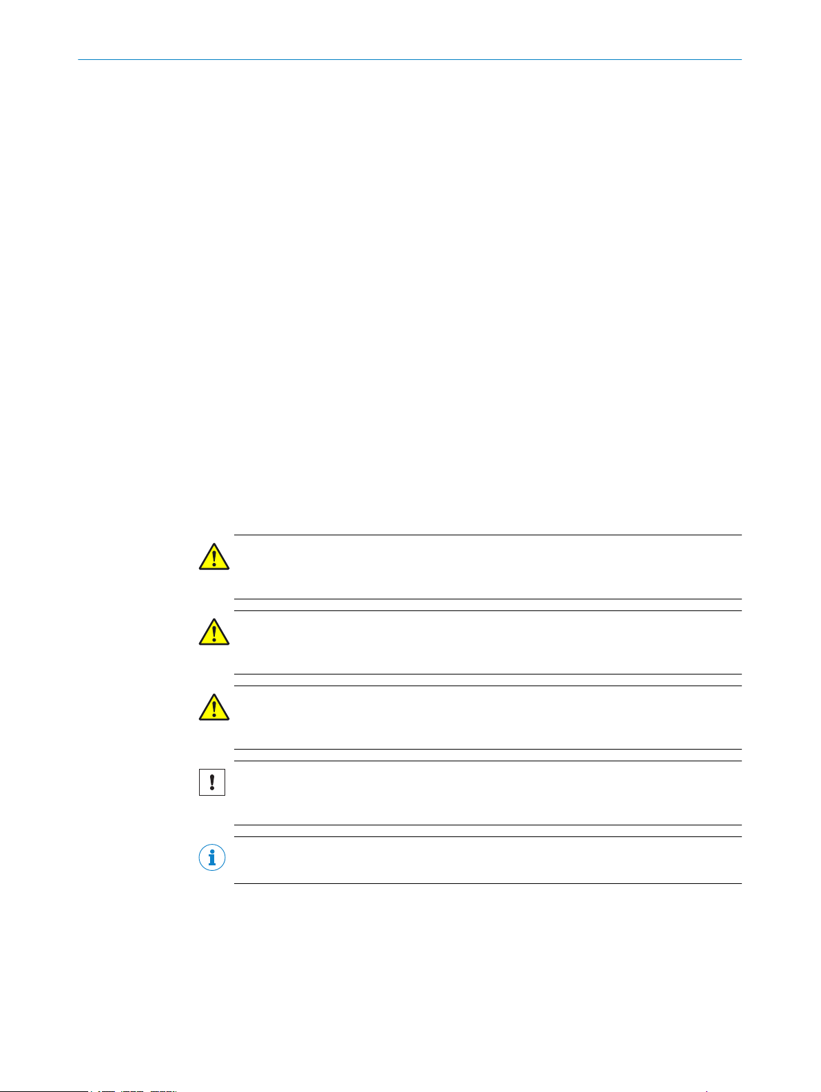
Safety notes and other notes
DANGER
Indic
ates a situation presenting imminent danger, which will lead to death or serious
injuries if not prevented.
WARNING
Indicates a situation presenting possible danger, which may lead to death or serious
injuries if not prevented.
CAUTION
ates a situation presenting possible danger, which may lead to moderate or minor
Indic
injuries if not prevented.
NOTICE
Indic
ates a situation presenting possible danger, which may lead to property damage if
not prevented.
NOTE
Indic
ates useful tips and recommendations.
Instructions to action
he arrow denotes instructions to action.
T
b
1. The sequence of instructions for action is numbered.
2. Follow the order in which the numbered instructions are given.
✓
The check mark denotes the result of an instruction.
4
T EC H NI C AL IN F OR M AT I ON | LiDAR Localization Hardware Integration 8024819/2019-09-02 | SICK
Subject to change without notice
Page 5

2 Safety information
2.1 General safety notes
DANGER
D
anger of using data output for safety function
Data output may only be used for general monitoring and control tasks.
Do not use data output for safety-related applications.
b
DANGER
Danger of using CoLa2 for safety function
CoLa2 may only be used for general monitoring and control tasks.
Do not use CoLa2 for safety-related applications.
b
SAFETY INFORMATION 2
8024819/2019-09-02 | SICK T E CH N IC A L I NF O RM A TI O N | LiDAR Localization Hardware Integration
Subject to change without notice
5
Page 6
3 SUP
PORTED HARDWARE
3 Supported hardware
3.1 2D LiDAR sensors
LiDAR-LOC is qualified for the SICK sensor family microScan3.
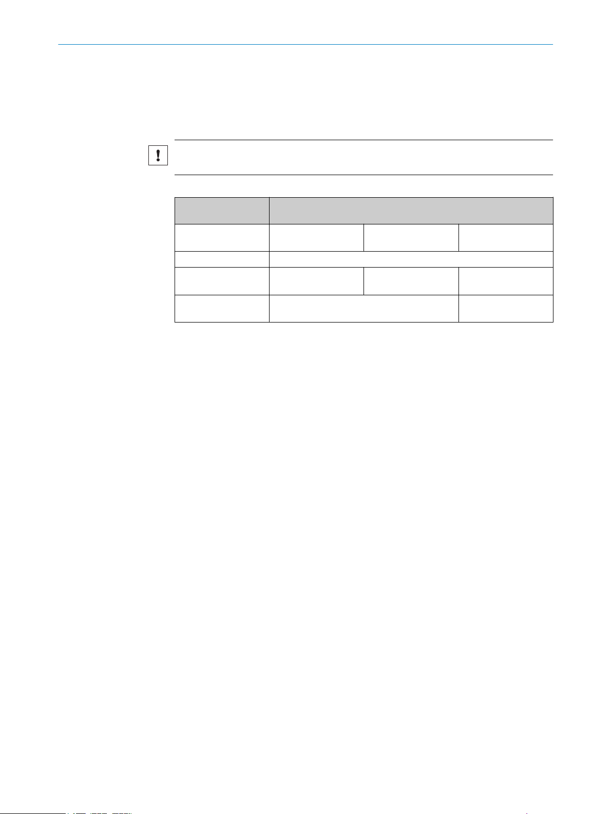
NOTICE
SIC
K does not guarantee that the system functions with other sensors.
Table 1: Supported sensor data
Supported sensor
ata
d
Supported device (pro‐
tective field range)
Aperture angle 275°
Distance range 1.8 %: 4 m
Scan cycle time 30 ms
2D LiDAR sensor
microScan3
4.0 m
100 %: 40 m
40 ms
microScan3
5.5 m
1.8 %: 5.5 m
100 %: 40 m
microScan3
9.0 m
1.8 %: 9 m
100 %: 64 m
40 ms
50 ms
For additional information, consult the operation instructions of the corresponding sen‐
.
sor
For high quality of the localization, we recommend to consider the following information
about the sensors.
microScan3
Protective field range 9 m (64 m warning field range)
•
The sensors with 64 m measurement range are preferred over the ones with 40 m
me
asurement range. They can be used in both configurations, 50 ms and 40 ms
scan cycle time. Smaller scan cycle times allow potentially higher velocities, how‐
ever, are primarily dependent on your risk assessment.
Pr
otective field range 4 m and 5.5 m (40 m warning field range)
•
When using the sensors with 40 m measurement range, they can be used in both
igurations, 40 ms and 30 ms scan cycle time, with corresponding 0.39° and
conf
0.51° resolution. A smaller scan cycle time allows potentially higher velocities. A
higher resolution allows the detection of smaller objects. However, the configura‐
tion is primarily dependent on your risk assessment.
Complementary information
ou can find additional information of the microScan3 in the operating instructions:
Y
8020198 microScan3 EtherNet/IP
•
8021217 microScan3 PROFINET
•
8021911 microScan3 EFI-pro
•
TM
3.2 Localization controllers
Localization controllers
iDAR-LOC uses the SIM1000-FXA. For quick integration, some information is provided
L
in this document.
6
T EC H NI C AL IN F OR M AT I ON | LiDAR Localization Hardware Integration 8024819/2019-09-02 | SICK
Subject to change without notice
Page 7

SUPPORTED HARDWARE 3
NOTICE
y default, the localization controller is a programmable device. When using the local‐
B
ization controller with the application software LiDAR-LOC, the controller is converted
into an application device. This means that the device cannot be programmed any
longer; it is locked for any additional application and cannot be unlocked.
Complementary information
Y
ou can find additional information of the localization controller in the operating instruc‐
tions 8023299.
8024819/2019-09-02 | SICK T E CH N IC A L I NF O RM A TI O N | LiDAR Localization Hardware Integration
Subject to change without notice
7
Page 8
4 DEVICE OVERVIEW
4 Device overview
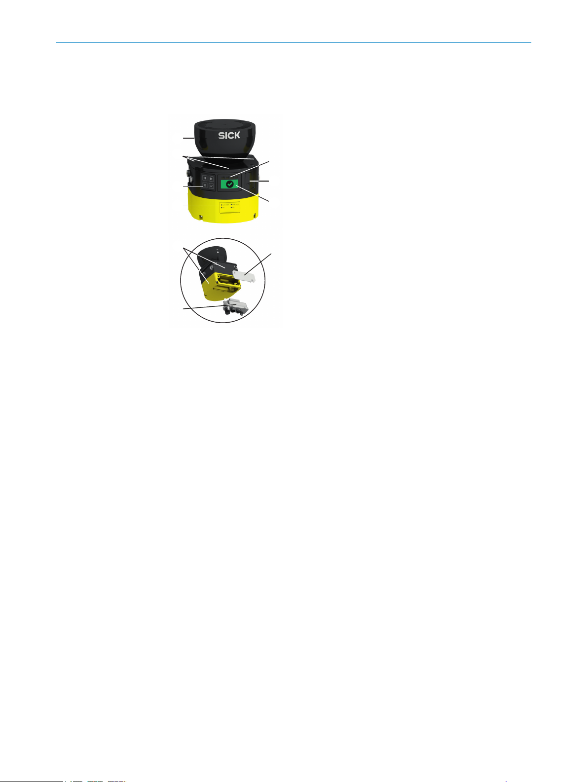
4.1 Device overview microScan3
Figure 1: microScan3 – overview
Optics cover
1
Display
2
Keypad
3
USB port
4
Status LEDs
5
Additional LEDs for ON state and OFF state
6
Network LEDs
7
Safety laser scanner without system plug
8
System plug
9
Cover plate
ß
8
T EC H NI C AL IN F OR M AT I ON | LiDAR Localization Hardware Integration 8024819/2019-09-02 | SICK
Subject to change without notice
Page 9

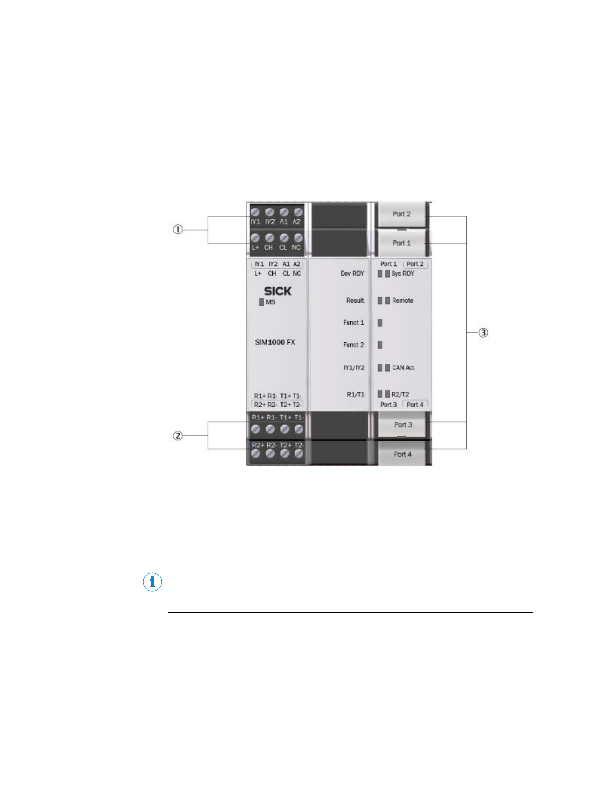
4.2 Device overview SIM1000 FXA
Figure 2: SIM1000 FXA – overview
Connections for switching input/output, IO-Link, CAN, and voltage supply
1
Serial connections
2
Ethernet connections
3
DEVICE OVERVIEW 4
8024819/2019-09-02 | SICK T E CH N IC A L I NF O RM A TI O N | LiDAR Localization Hardware Integration
Subject to change without notice
9
Page 10
XD1 XF1 XF2
5 ELECTRICAL INSTALLATION
5 Electrical installation
5.1 Important notes
Information on the requirements that must be met for safe integration of the localiza‐
ion controller and 2D LiDAR sensors into the control and electronics of the machine,
t
see the corresponding operating instructions.
DANGER
H
azard due to electrical voltage
Hazard due to unexpected starting of the machine
Make sure that the machine is (and remains) disconnected from the power supply
b
during the electrical installation.
Make sure that the dangerous state of the machine is (and remains) switched off.
b
arry out the electrical installation work in conformity with EN 60204-1.
C
b
Use suitable power supply.
b
Check that all earthing points are connected with the same ground potential.
b
Connect the shielding of all data lines (Ethernet, CAN, serial) directly to the func‐
b
tional earth (FE) at the control cabinet entry point.
5.2 MicroScan3
The electrical installation is described in detail in the operating instructions:
The examples are given for microScan3 EFI-pro variant but are also applicable for Ether‐
Net/IP™ and PROFINET.
5.2.1 Electrical setup
Supply voltage and power consumption
Suppl
The microScan3 consumes the following:
System plug and connections
T
8021911
•
y voltage:
24 V DC (16.8 … 30 V DC) (SELV/PELV) according to IEC 60364441
•
Must be able to bridge a brief power outage of 20 ms with a starting voltage of
•
≤ 3 A
Power consumption ≤ 11 W (typ. 7.2 W)
•
Power consumption Standby typical 7 W
•
able 2: Position of the electrical connections
Safety laser scan‐
s
ner
microScan3 – Ether‐
Net/IP™
Suitable system plug Plug connector
XD1: voltage supply,
•
XF1, XF2: 2 × Ethernet
•
for EtherNet/IP –
CIP Safety, data output,
configuration, and diag‐
nostics.
MICSX-BANNZZZZ1 (part number:
2086102)
10
T EC H NI C AL IN F OR M AT I ON | LiDAR Localization Hardware Integration 8024819/2019-09-02 | SICK
Subject to change without notice
Page 11

12
3 4
43
2 1
ELECTRICAL INSTALLATION 5
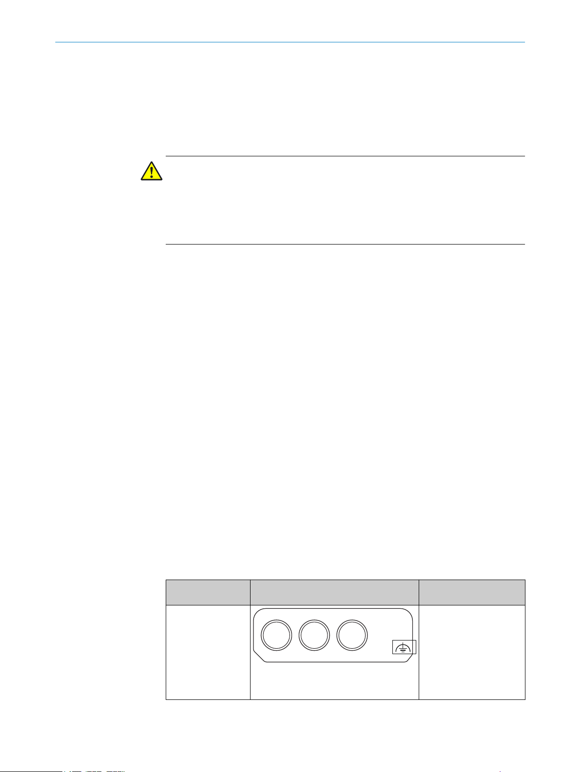
Voltage supply (XD1)
V
oltage supply is supplied via a 4-pin, A-coding M12 male connector on the device side.
Figure 3: Pin assignment of the voltage supply (male connector, M12, 4-pin, A-coded)
Table 3: Pin assignment of the voltage supply
Pin Marking Function Wire color
1 +24 V DC 24 V DC supply voltage Brown
2 NC Not connected White
3 0 V DC 0 V DC supply voltage Blue
4 FE Functional earth/shield Black
1)
Applies to the connecting cables recommended as accessories.
Ethernet for EFI-pro, data output, configuration, and diagnostics (XF1, XF2)
1)
On t
connectors. There is a network switch in the safety laser scanner which connects the
two Ethernet female connectors. The two Ethernet female connectors therefore have
the same function. The pin assignment corresponds to EN 61918, Appendix H.
Figure 4: Ethernet pin assignment (female connector, M12, 4-pin, D-coding)
Table 4: Ethernet pin assignment
Pin Designation Function
1 TX+ Send data +
2 RX+ Receive data +
3 TX– Send data -
4 RX– Receive data -
Housing SH Shielding
5.3 SIM1000 FXA
The electrical installation is described in detail in the operating instructions:
he device side, Ethernet and EFI-pro are connected via 4-pin, D-coding M12 female
8023298
•
8024819/2019-09-02 | SICK T E CH N IC A L I NF O RM A TI O N | LiDAR Localization Hardware Integration
Subject to change without notice
11
Page 12
5 ELE
CTRICAL INSTALLATION
5.3.1 Preparations and overview
Preparing the electrical installation
T
o carry out the electrical installation, you will need:
Connection cables for the peripheral devices, including the corresponding data
•
sheets
Voltage supply cable
•
If customers assemble the cables: crimping tool, ferrules, soldering iron, and other
•
installation material
Overview of connections
Terminal block 1 and 2
1
Terminal block 3 and 4
2
Ethernet connections
3
5.3.2 Pin allocations of the connections
Important information
NOTE
he SIM1000 FXA device is supplied with power from an external power supply unit via
T
the pins A1 and A2.
Pin allocations of the connections
Onl
y the pins for supply voltage, ground, and input/outputs are used in the LiDAR local‐
ization applica-tion.
For the power supply of the SIM1000 FXA, connect the open ends of the power supply
cable to the pins of the terminal block 1.
When using the CoLa-A synchronization methods, connect the I/O port of the vehicle
controller with IY2 of the terminal block 2 of the SIM1000 FXA.
12
T EC H NI C AL IN F OR M AT I ON | LiDAR Localization Hardware Integration 8024819/2019-09-02 | SICK
Subject to change without notice
Page 13
ELECTRICAL INSTALLATION 5
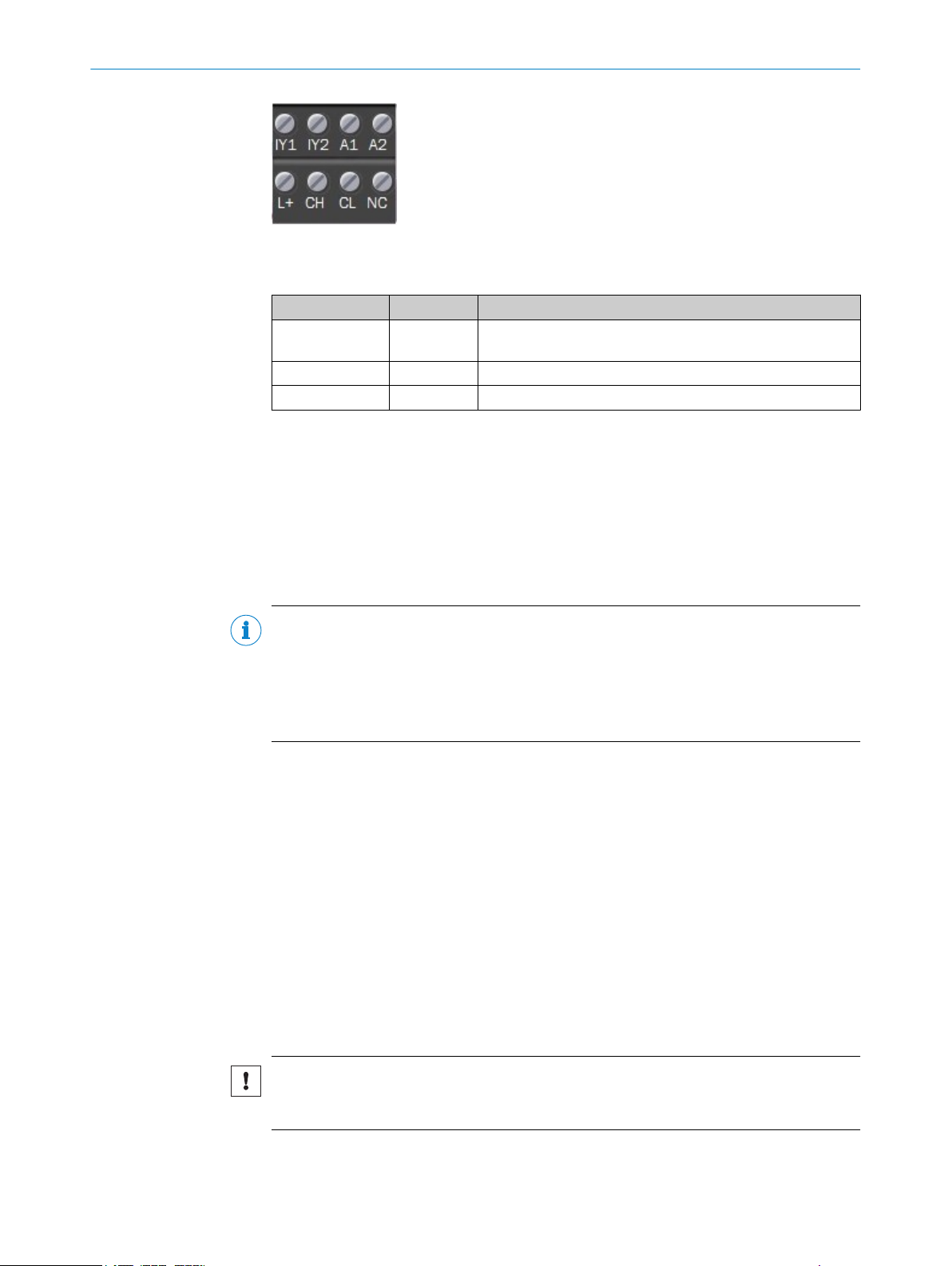
Figure 5: Terminal block 1 and 2
T
able 5: Pin allocations of the connections
Designation Signal Function
IY2 Output 1 Synchronization I/O when using command L
stamp
A1 +24 V Supply voltage IN
A2 GND Ground
Switching output
x. output current: 100 mA
Ma
•
Min. high output logic level: VCC – 3 V
•
Max. low output logic level: 3 V
•
Push/Pull, NPN, PNP configurable
•
ocRequestTime‐
5.3.3 Network setup
5.3.3.1 Preset Ethernet interfaces
NOTE
eset IP addresses of the Ethernet interfaces:
Pr
Port 1: 192.168.0.1 (e.g. connection to the service computer)
•
Port 2: 192.168.1.1 (e.g. connection to the 2D LiDAR sensor)
•
Port 3: 192.168.2.1 (e.g. connection to the vehicle controller)
•
Port 4: 192.168.3.1
•
When expanding the GigE interfaces with one or more Ethernet switches, it is essential
t
o use only jumbo-frame compatible GigE switches. Switches limited to just 100 MB do
not support the data packet mode used by cameras and can cause transmission
errors.
Changing the IP addresses
The individual IP addresses can be changed using the SICK SOPAS ET PC tool. This is
described in detail in the “SIM Getting Started Guide”, which is available for download
from the SICK AppSpace area of the SICK Support Portal. This guide also includes fur‐
ther notes on how to connect SICK sensors and the SICK picoCam and midiCam cam‐
eras to the Ethernet interfaces.
5.3.3.2 Ethernet connections
Important information
NOTICE
S
hielded Ethernet cables must be used. The shielding of the Ethernet cables must be
connected to functional earth.
8024819/2019-09-02 | SICK T E CH N IC A L I NF O RM A TI O N | LiDAR Localization Hardware Integration
Subject to change without notice
13
Page 14

5 ELE
CTRICAL INSTALLATION
Ethernet connections
Figure 6: Ethernet connections
P
ort 1: 100 MBit/s
Port 2: 1 GBit/s
Port 3: 100 MBit/s
Port 4: 1 GBit/s
5.3.3.3 Connecting peripheral devices
The device can be connected to a wide range of sensors and cameras.
T
he required pin assignments can be found in the data sheets for the peripherals to be
connected as well as in the relevant connection descriptions.
Connect the cables to peripheral devices.
•
Route the cables to the device using installation materials (cable channels, cable
•
ties, etc.). When doing so, pay attention to cable strain relief.
Connect cables to the relevant device connections and screw together tightly.
•
Further topics
in allocations of the connections", page 12
"P
•
14
T EC H NI C AL IN F OR M AT I ON | LiDAR Localization Hardware Integration 8024819/2019-09-02 | SICK
Subject to change without notice
Page 15

5.3.3.4 Example connections
Figure 7: Example of a connection with SIM1000 FXA, a service computer (PC), and one 2D
iDAR sensor
L
ELECTRICAL INSTALLATION 5
Figure 8: Example of a connection with SIM1000 FXA, a service computer (PC), a switch, a SICK
afety controller, and two 2D LiDAR sensors
s
8024819/2019-09-02 | SICK T E CH N IC A L I NF O RM A TI O N | LiDAR Localization Hardware Integration
Subject to change without notice
15
Page 16

5 ELE
CTRICAL INSTALLATION
Figure 9: Example of a connection with SIM1000 FXA, a service computer (PC), a SICK safety
ontroller, and two 2D LiDAR sensors
c
16
Figure 10: Example of a connection with a SIM1000 FXA, a service computer (PC), a SICK safety
ontroller, two 2D LiDAR sensors, and measurement data to the vehicle controller
c
T EC H NI C AL IN F OR M AT I ON | LiDAR Localization Hardware Integration 8024819/2019-09-02 | SICK
Subject to change without notice
Page 17

MICROSCAN3 CONFIGURATION OF THE DATA OUTPUT 6
6 MicroScan3 configuration of the data output
6.1 Important notes
Using the safe 2D LiDAR sensor does require the safety-related functions of the sensor
o be fully configured. The configuration needs to be valid and verified and the sensor
t
must not be in error mode.
When using PROFINET scanners, the inputs have to be configured in the same way as
the scanner is integrated. E.g. if there is an input signal configured, the input source
has to be electrically applied.
6.2 Overview
For more information on the microScan3’s data output via UDP and TCP/IP, refer to the
doc
ument with the following SICK part numbers:
8022706
•
DANGER
Danger of using data output for safety function
Data output may only be used for general monitoring and control tasks.
Do not use data output for safety-related applications.
b
Data output allows for the output of measurement data and other data via the Ethernet
erface. Other network participants, the receivers, can call up and use the data.
int
The data output works in different send modes:
On request: Data is output when there is an explicit request from a host computer
•
via TCP/IP using CoLa2
Continuous and on request: Data is output continuously via UDP to a defined target
•
address and also when there is an explicit request from a host computer via
TCP/IP using CoLa2
6.3 Activating and configuring data output
You can activate and configure the data output in two ways:
ith the Safety Designer
W
•
Via the CoLa2 protocol
•
8024819/2019-09-02 | SICK T E CH N IC A L I NF O RM A TI O N | LiDAR Localization Hardware Integration
Subject to change without notice
17
Page 18
6 MICR
OSCAN3 CONFIGURATION OF THE DATA OUTPUT
6.4 Single receiver of measurement data
6.4.1 Configuring with the Safety Designer
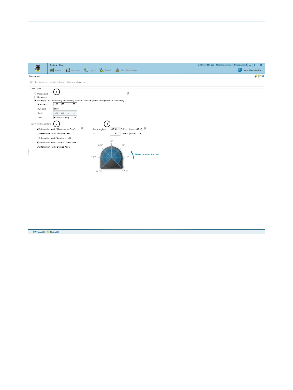
Overview
Figure 11: Data output
Send mode
1
Data content
2
Angular range
3
18
T EC H NI C AL IN F OR M AT I ON | LiDAR Localization Hardware Integration 8024819/2019-09-02 | SICK
Using Safety Designer, you can configure the safety laser scanner and the data output.
A c
onfiguration that is created with the Safety Designer is saved in the device and is
also active after restarting the device.
Send mode
Deactivated: Data output is deactivated
•
On request: Data is output when there is an explicit request from a host computer
•
via TCP/IP using CoLa2
Continuous and on request: Data is output continuously via UDP to a defined target
•
address and also when there is an explicit request from a host computer via
TCP/IP using CoLa2
Data content
Measurement data: Distance data with reflector detection and RSSI
•
Field interruption: Data on the light beams in interrupted fields of the active monitor‐
•
ing case
Subject to change without notice
Page 19

MICROSCAN3 CONFIGURATION OF THE DATA OUTPUT 6
ation data: Status of inputs and outputs that are used in the monitoring case
Applic
•
table
Device status: Information on the status of the safety laser scanner (e.g., cut-off
•
paths, errors)
Configuration of data output: Information on the angular range actually being used
•
(for technical reasons, data from a slightly larger angular range than the one set
may be output in some cases)
Angular range
You can define the range within which measurement data and data relating to field
interruptions is output.
6.5 Multiple receivers of measurement data via broadcast
Overview
If y
ou want to transmit measurement data from the safety laser scanner to multiple
clients, you must use broadcasting.
For the default Ethernet configuration of the SIM, the port 2 is:
IP: 192.168.1.1
•
Subnet mask: 255.255.255.0
•
The broadcast IP address for this subnet (derived from IP of the SIM) is:
192.168.1.255
•
Important information
NOTE
W
hen using multiple LiDARs, a different receiver port for each sensor must be config-
ured (UDP port). For example:
UDP port Safety Scanner 1: 6060
•
UDP port Safety Scanner 2: 6061
•
If multiple sensors use the same receiver port, the scans may interfere with each other.
This may cause a fault in LiDAR-LOC or any customer application. Setting a receiver port
number in the range between 51000 and 51100 may cause interference with other
sensor configurations and should be avoided.
NOTE
hen localizing, please close the SICK Safety Designer. The CoLa-A communication of
W
the SICK Safety Designer interferes with the CoLa-A communication of LiDAR-LOC.
Approach
1.
In the Safety Designer, open Configuration → Addressing.
2. In the section IP address, configure the Ethernet interface IP of the microScan3 to
an unused IP address in the subnet, e.g. 192.168.1.2.
8024819/2019-09-02 | SICK T E CH N IC A L I NF O RM A TI O N | LiDAR Localization Hardware Integration
Subject to change without notice
19
Page 20

6 MICROSCAN3 CONFIGURATION OF THE DATA OUTPUT
Figure 12: Setting the IP address with the SICK Safety Designer
3. In D
ata output, choose On request and additionally continuously.
4. In section Send Mode, enter the IP address of the target computer to the broadcast
UDP address, e.g. 192.168.1.255.
5. Enter the UDP port, for example, 6060.
6. In Send, select Every Measuring.
7. In section Selection data content, select the information blocks Measurement Data and
Derived Values.
20
Figure 13: Configuring the data output with the SICK Safety Designer
T EC H NI C AL IN F OR M AT I ON | LiDAR Localization Hardware Integration 8024819/2019-09-02 | SICK
Subject to change without notice
Page 21

7 Operation
7.1 Status LEDs SIM1000 FXA
Status LEDs SIM1000 FXA
hen the device is operating, the operational status of the connections is indicated
W
visually by status LEDs.
Using these status indicators, the operator can find out quickly and easily whether the
device and the peripherals are working properly or whether any faults or errors have
occurred.
Monitoring the visual indicators is part of the routine inspection carried out on the
device and the machine/plant area into which the device is incorporated.
Table 6: Meaning of symbolse
Symbol Meaning
OPERATION 7
LED off
LED on
LED flashes
LED goes out briefly
LED lights up briefly
Situation and function of the LEDs
T
able 7: Situation and function of the LEDs
Designation LED behavior Description
2)
MS
Dev RDY Runlevel READY, no errors detected.
Voltage connected.
Runlevel READY, boot process error.
1)
Sys RDY Application software LiDAR-LOC is booting
Application software LiDAR-LOC is ready
8024819/2019-09-02 | SICK T E CH N IC A L I NF O RM A TI O N | LiDAR Localization Hardware Integration
Subject to change without notice
21
Page 22

7 OPERATION
Designation LED behavior Description
Result Localization is disabled/not running
Localization is running and application results
ar
e available
Funct 1
Sensor is not configured or cannot be con‐
ted to
nec
All active sensors are OK and are providing
ata
d
One of the active sensors is not supported, or
there is an error in the configuration, or the
sensor was unplugged during operation
Funct 2 Reserved
IY1 / IY2 Voltage not applied to the connection.
Voltage applied. No signal activity.
Voltage applied. Signal activity.
Voltage not applied to the connection. Signal
tivity.
ac
22
Link
Connection not established with Ethernet.
Connection established with Ethernet.
Act No activity.
Data transmission via Ethernet.
1)
Time delay before availability due to boot process (approx. 20 s)
2)
Module status
T EC H NI C AL IN F OR M AT I ON | LiDAR Localization Hardware Integration 8024819/2019-09-02 | SICK
Subject to change without notice
Page 23

8 List of figures
1. microScan3 – overview................................................................................................ 8
2. SIM1000 FXA – overview............................................................................................. 9
3. Pin assignment of the voltage supply (male connector, M12, 4-pin, A-coded)...... 11
4. Ethernet pin assignment (female connector, M12, 4-pin, D-coding)...................... 11
5. Terminal block 1 and 2...............................................................................................13
6. Ethernet connections................................................................................................. 14
7. Example of a connection with SIM1000 FXA, a service computer (PC), and one 2D
8. Example of a connection with SIM1000 FXA, a service computer (PC), a switch, a
9. Example of a connection with SIM1000 FXA, a service computer (PC), a SICK
10. Example of a connection with a SIM1000 FXA, a service computer (PC), a SICK
11. Data output.................................................................................................................18
12. Setting the IP address with the SICK Safety Designer............................................. 20
13. Configuring the data output with the SICK Safety Designer....................................20
LIST OF FIGURES 8
iDAR sensor...............................................................................................................15
L
SICK safety controller, and two 2D LiDAR sensors...................................................15
safety controller, and two 2D LiDAR sensors............................................................16
safety controller, two 2D LiDAR sensors, and measurement data to the vehicle
controller..................................................................................................................... 16
8024819/2019-09-02 | SICK T E CH N IC A L I NF O RM A TI O N | LiDAR Localization Hardware Integration
Subject to change without notice
23
Page 24

9 LIST OF TABLES
9 List of tables
1. Supported sensor data................................................................................................. 6
2. Position of the electrical connections....................................................................... 10
3. Pin assignment of the voltage supply........................................................................11
4. Ethernet pin assignment............................................................................................11
5. Pin allocations of the connections............................................................................ 13
6. Meaning of symbolse................................................................................................. 21
7. Situation and function of the LEDs............................................................................21
24
T EC H NI C AL IN F OR M AT I ON | LiDAR Localization Hardware Integration 8024819/2019-09-02 | SICK
Subject to change without notice
Page 25

Detailed addresses and further locations at www.sick.com
Australia
Phone +61 (3) 9457 0600
1800 33 48 02 – tollfree
E-Mail sales@sick.com.au
Austria
Phone +43 (0) 2236 62288-0
E-Mail office@sick.at
Belgium/Luxembourg
Phone +32 (0) 2 466 55 66
E-Mail info@sick.be
Brazil
Phone +55 11 3215-4900
E-Mail comercial@sick.com.br
Canada
Phone +1 905.771.1444
E-Mail cs.canada@sick.com
Czech Republic
Phone +420 234 719 500
E-Mail sick@sick.cz
Chile
Phone +56 (2) 2274 7430
E-Mail chile@sick.com
China
Phone +86 20 2882 3600
E-Mail info.china@sick.net.cn
Denmark
Phone +45 45 82 64 00
E-Mail sick@sick.dk
Finland
Phone +358-9-25 15 800
E-Mail sick@sick.fi
France
Phone +33 1 64 62 35 00
E-Mail info@sick.fr
Germany
Phone +49 (0) 2 11 53 010
E-Mail info@sick.de
Greece
Phone +30 210 6825100
E-Mail office@sick.com.gr
Hong Kong
Phone +852 2153 6300
E-Mail ghk@sick.com.hk
Hungary
Phone +36 1 371 2680
E-Mail ertekesites@sick.hu
India
Phone +91-22-6119 8900
E-Mail info@sick-india.com
Israel
Phone +972 97110 11
E-Mail info@sick-sensors.com
Italy
Phone +39 02 27 43 41
E-Mail info@sick.it
Japan
Phone +81 3 5309 2112
E-Mail support@sick.jp
Malaysia
Phone +603-8080 7425
E-Mail enquiry.my@sick.com
Mexico
Phone +52 (472) 748 9451
E-Mail mexico@sick.com
Netherlands
Phone +31 (0) 30 229 25 44
E-Mail info@sick.nl
New Zealand
Phone +64 9 415 0459
0800 222 278 – tollfree
E-Mail sales@sick.co.nz
Norway
Phone +47 67 81 50 00
E-Mail sick@sick.no
Poland
Phone +48 22 539 41 00
E-Mail info@sick.pl
Romania
Phone +40 356-17 11 20
E-Mail office@sick.ro
Russia
Phone +7 495 283 09 90
E-Mail info@sick.ru
Singapore
Phone +65 6744 3732
E-Mail sales.gsg@sick.com
Slovakia
Phone +421 482 901 201
E-Mail mail@sick-sk.sk
Slovenia
Phone +386 591 78849
E-Mail office@sick.si
South Africa
Phone +27 10 060 0550
E-Mail info@sickautomation.co.za
South Korea
Phone +82 2 786 6321/4
E-Mail infokorea@sick.com
Spain
Phone +34 93 480 31 00
E-Mail info@sick.es
Sweden
Phone +46 10 110 10 00
E-Mail info@sick.se
Switzerland
Phone +41 41 619 29 39
E-Mail contact@sick.ch
Taiwan
Phone +886-2-2375-6288
E-Mail sales@sick.com.tw
Thailand
Phone +66 2 645 0009
E-Mail marcom.th@sick.com
Turkey
Phone +90 (216) 528 50 00
E-Mail info@sick.com.tr
United Arab Emirates
Phone +971 (0) 4 88 65 878
E-Mail contact@sick.ae
United Kingdom
Phone +44 (0)17278 31121
E-Mail info@sick.co.uk
USA
Phone +1 800.325.7425
E-Mail info@sick.com
Vietnam
Phone +65 6744 3732
E-Mail sales.gsg@sick.com
8024819/2019-09-02/en
SICK AG | Waldkirch | Germany | www.sick.com
 Loading...