

Page 1

en
Lector®632
Image-based code readers
QUICKSTART
Mount
Assemble the optical kit on the Lector63x. For details
see section C at the end of this quickstart.
NOTICE
SOPAS ET main window
The SOPAS ET main window is split into two panes,
the project view to the left and a list of connected devices to the right. To add the Lector63x to the project,
drag the device to the left project pane.
Additional expandable panels are available to the left
of and below the image area.
Use only Lector63x optics to ensure optimal image
quality and to avoid damage to the device.
Mount the device at a suitable working distance from
the object, for example using a mounting bracket
(angled bracket part no. 2076735, cooling bracket
2078970, or bracket kit 2076735). For information
about suitable working distances, see section E.
1. Filmstrip
2. Information area
Double-click the product icon to open the device
window and start the conguration.
If there are IP address connection issues, click the
Fig. 1: Mounting
Mount the Lector63x with a 10 to 20 degree tilt to
avoid reections.
Connect
To connect the Lector63x:
Product information
The Lector63x is an industrial image-based code
reader family for all common 1D (bar codes / stacked
codes) and 2D (matrix) codes. The result is sent to the
control system via digital output or its host interfaces:
Serial, CAN or Ethernet.
The Lector63x Flex variants feature exchangeable S-
or C-mount optics, internal lighting and lter options
to meet a wide range of application requirements.
About this document
This quickstart contains instructions that support
the set up and operation of the Lector63x Flex. Make
sure that the installation is performed by a qualied
technician.
This quickstart as well as the Lector63x operating
instructions, containing additional information, are
available in English and German online. To download:
www.SICK.com > type a document number in the
number eld: quickstart EN/DE, 8018061/8018060,
operating instructions EN/DE, 8018071/8018070.
8018061/2015-04-13• Subject to change without notice • SICK AG • Waldkirch • Germany • www.sick.com 1Lector®632 | SIcK
Part
1. Connect the Gigabit Ethernet to a network or
directly to a PC.
2. Connect the power I/O to a 24 V power source.
WARNING
Ensure that the ground potential is the same at all
grounding points. Incorrect grounding or connection
can damage the device and cause re.
Ensure that any loose cable ends are isolated. Do
not connect external I/O signals to the Lector63x
while it is powered.
Congure with PC
The SOPAS Engineering Tool (ET) software for PC is
used to connect and congure the Lector63x and
other SICK devices.
To install SOPAS ET:
1. Download SOPAS ET (version 3.0.1 or newer)
from www.mysick,com/en/SOPAS_ET.
2. Run the downloaded installation le.
3. Follow the instructions on the screen.
text next to the warning symbol in the project pane to
make adjustments.
If the device driver is missing, click the text next to
the warning symbol in the project pane and follow the
instructions. The device will be in ofine mode after
installing the driver. Put the device in online mode by
clicking the
Offline button next to the product icon.
SOPAS ET device window
The Lector63x is congured in the SOPAS ET device
window. The code in the image below can be used to
test your device.
1. SOPAS functions
2. Image handling controls
3. Device controls
4. Parameter pane with workow
5. Image area
Device controls
The device controls are used to change between
image acquisition modes and to activate related
functions.
Button Mode Description
Stop Stops image acquisition.Exter-
Live Activates live image acquisi-
Operation Activates image acquisition
Button Function Description
Manual
trigger
Start trigger Start image series
Stop trigger Stop image series
Record Records images to a folder on
Settings Recording settings.
nal interfaces including inputs
are disabled. The device does
not receive triggers.
tion. External interfaces are
disabled.
as congured in the triggering
settings. External interfaces are
enabled.
Trigger a single image
(single image mode).
(image series mode).
(image series mode).
the PC.
Page 2
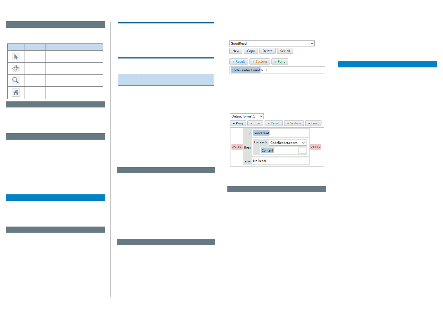
Image handling controls
The image handling controls are used to change how
images are viewed.
Button Function Description
Select Click and drag to change region
Move Click and drag to move the image.
Zoom Click and drag upwards to zoom in
Home Click to t image area to view.
size and position.
and downwards to zoom out.
Filmstrip
The expandable lmstrip area shows the image history as thumbnails. When the image acquisition is
stopped it is possible to click a thumbnail to see it
enlarged.
Information area
The expandable information area contains the Device
infO, lOgs and system status tabs.
Device infO tab displays device-related information
The
such as IP address and serial number.
lOgs tab contains controls to retrieve logged
The
images.
system status tab shows system warnings and
The
errors.
Workow
Follow the workow in the parameter panel to congure the Lector63x. While the steps are arranged in the
typical conguration order, it is possible to navigate
freely between the steps.
1. Image
The image workow step controls how and when im-
ages are acquired.
lens & fOcus section controls lens type selection
The
and displays focus feedback.
brightness section controls the visual quality of
The
acquired images. Use the autO gain button to automatically adjust the gain.
illuminatiOn section controls the internal and exter-
The
nal lighting behavior. The internal lighting is enabled
by default.
NOTICE
For Lector632x Flex, the focusing of the image is
done mechanically on the device (S-mount) or on
the lens (C-mount). To protect the device (S-mount)
from focus manipulation attach the supplied round
label to the hole in the device lid.
The
triggering section controls the acquisition mode
and triggering method:
Acquisition
mode
Single image • Acquires one image and outputs one
Image series • Acquires a series of images and typically
Image series is enabled by default.
Description
result per trigger signal.
• Used when there is only one acquisition
and analysis per object.
• Used when the code is precisely
positioned on the object in high speed
applications.
outputs one combined result per trigger
signal.
• Used when the object is larger than the
eld of view and the exact code position
is unknown.
• Used to increase read rate by acquiring
each code multiple times.
2. Task
The task workow step contains the code reading
parameters.
cODe reaDer settings section determines which
The
code types to read. Advanced settings are available
for performance optimization.
cODe reaDer results section contains unformatted
The
results for the current image, such as the read result
and code print quality.
The results are presented in a table where each row
represents one code.
3. Results
The results workow step contains settings for result
timing, post-processing and formatting.
OutPut cOntrOl section determines when the result
The
shall be output, either:
• Directly when processing is ready
• At a xed response time
The
cOunters section contains counters which for
example can be used to set conditional outputs.
The cOnDitiOns section allows creation of custom conditions for device control and result logic. The gOODreaD
condition is pre-dened as an example:
The Digital OutPuts section species which results are
published on the available outputs.
OutPut fOrmat section, the decoding result
In the
can be formatted to a string in a visual editor. The
example below shows how the GoodRead condition is
used to output the content of all read codes.
The beePer, functiOn leD and feeDback sPOtlight sec-
tions contain settings to dene custom outputs for
monitoring results without a screen.
4. Interfaces
The interfaces workow step contains settings for con-
nections to external interfaces.
i/O DefinitiOns section denes the physical behav-
The
ior of the digital inputs and outputs.
ethernet section sets up Ethernet communica-
The
tions with peripheral equipment.
serial section sets up serial communications with
The
peripheral equipment.
lOgging section controls logging of data from the
The
device to internal and external destinations: Device
RAM, MicroSD card and external FTP server.
encODer section sets up one of the digital inputs
The
to receive encoder signals. For example, incrementcontrolled acquisition and result output make the
system independent of conveyor speed.
master/slave section sets up camera-to-camera
The
communication in a SICK CAN network.
functiOn buttOns On Device section denes the
The
behavior of the device buttons.
Device time section species how to set the device
The
time manually or to synchronize with an external time
server.
License text
SICK uses open source software in its Lector63x sensors. This software is licensed by the rights holders
using the following licenses among others: the free
licenses GNU General Public License (GLP Version2,
GPL Version3) and GNU Lesser General Public
License (LGPL), the MIT license, zLib license, and the
licenses derived from the BSD license.
This Program is distributed in the hope that it will be
useful, but WITHOUT ANY WARRANTY; without even
the implied warranty for merchantability or tness
for a particular purpose. See the GNU General Public
License for more details.
View the complete license texts here: www.sick.com/
licencetexts. A printed copy of the license texts is also
available on request.
8018061/2015-04-13• Subject to change without notice • SICK AG • Waldkirch • Germany • www.sick.com 2Lector®632 | SIcK
Page 3

A. Dimensional drawings
5.9
12
56
è
11
7
10
16
1
2
4
3
1
2
3
4
7
6
1
2
3
4
5
1. External light connector
2. Gigabit Ethernet connector
3. USB connector
4. Power, serial, CAN and I/O connector
5. 23 mm protection hood for lens and lighting
6. 38 mm protection hood for lens and lighting
7. Plug to ensure IP67 for unused connectors
8. Blind hole thread M5, 5.5 mm deep (4 x)
9. Sliding nut M5, 5.5 mm deep (4 x)
ß Integrated lighting connector
à Aiming laser (2 x)
á S- or C-mount optical module
â Blind hole thread 2.5 mm (4 x) for mounting
integrated lighting
ã Optical axis and center of image sensor
(4.25)
ä Manual focus screw, hidden under cover/
108
sticker (S-mount Flex)
å Function button (2 x)
æ Bar graph LED display (5 x)
ç Removable cover for microSD card and
manual focus screw
è Status LED display (5 x 2 levels)
8
(3.61)
91.8
(0.23)
6.5
(0.26)50(1.97)
23.9
(0.94)
9
45.8
(1.80)
3
4
0.5
(0.05)
min. 8 – max. 50
(0.31 – 1.97)
á
à
ß
(2.32)
59
63.1
(2.48)
â
7
ã
10.8
(2.91)
74
(3.02)
76.6
(0.43)
å
ä
æ
ç
B. Connection diagram
External light
ICL
1
Connection
box
3
FIeldbuses
I/O
box
24 V DC
Encoder
Photoelectric
switch
8018061/2015-04-13• Subject to change without notice • SICK AG • Waldkirch • Germany • www.sick.com 3Lector®632 | SIcK
External light
Power I/O
USB
2
â
4
5
6
7
Ethernet
ã
External light
VLR + CCS
8
9
PC
ß
FTP
à
á
HMI
PLC
1. External light (ICL)
2. Connection box
3. Fieldbuses
4. I/O box
5. 24 V DC, power source
6. Encoder
7. Photoelectric switch
8. External light (VLR + CCS)
9. PC
ß External FTP server
à HMI, operator interface
á PLC, control system
â Power cable, for example no. 2055419
(2 m)
ã Ethernet cable, for example no. 6034414
(2 m)
C. Optical conguration
Example with compact C-mount optics:
2
1
6
7
3
8
D. Pin assignment
Power/SerialData/
CAN/IO
15
8
9
1
13
2
12
3
Pin Signal Signal Signal Signal
1 Ground +5V DC 24V switchable out TRD0_P
DC 24V +20% - Data - TRD0_N
2
3 CAN L + Data Ground TRD1_P
4 CAN H Ground - TRD1_N
5 TD+ (RS 422/485) TRD3_P
6 TD- (RS422/485)
TxD (RS 232)
7 TxD (RS 232) TRD2_P
8 RxD (RS 232) TRD2_N
9 Sens GND
10 Input 1
11 RD+ (RS 422/485)
12 RD- (RS 422/485)
RxD (RS 232)
13 Input/output 3
14 Input/output 4
15 Input 2
16 Input/output 5
17 Input/output 6
17
6
14
5
4
USB
(no image transfer)
4
9
5
ß
à
External light Gb Ethernet
1. Optical module (C-mount)
2. Focus locking screws
3. Spacers
4. Integrated lighting
5. Protection hood
6. Metallic screws
7. Integrated lighting connector extension
8. Focus adjustment ring
9. Filter ring (replace with lter)
ß Black screws
à Filter holder
Note: parts vary between optical
congurations. To prevent focus
changes, x the C-mount lens with
at least one of the supplied screws
before starting operation.
TRD3_N
8
Page 4

E. Field of view diagram
Field of view width x height in mm² (sq inch), typical values
Working distance in mm (inch)
Min. resolution in mm (mil)
Field of view width x height in mm² (sq inch), typical values
Working distance in mm (inch)
Min. resolution in mm (mil)
f = 12.0 mm
f = 12.5 mm
f = 16.0 mm
f = 17.5 mm
f = 25.0 mm
f = 35.0 mm
f = 50.0 mm
Short range up to 0.3 m working distance
300 x 225
(11.81 x 8.86)
200 x 150
(7.87 x 5.91)
100 x 75
(3.94 x 2.95)
0
0 200
100
(3.94)
a
(7.80)
1D code 2D code
b
c
0.2
(7.9)
d
e
f
0.1
g
(3.9)
h
i
0.05
(2.0)
j
300
(11.81)
0.3
(11.8)
0.2
(7.9)
0.1
(3.9)
0.05
(2.0)
Lens focal length
a: f = 6.0 mm
b: f = 8.0 mm
c: f = 9.6 mm
d:
e:
f:
g:
h:
i:
j:
Long range up to 2.2 m working distance
1,200 x 900
(47.24 x 35.43)
1,000 x 750
(39.37 x 29.53)
800 x 600
(31.50 x 23.62)
2
600 x 450
(23.62 x 17.72)
400 x 300
(15.75x 11.81)
200 x 150
(7.87 x 5.91)
0
0 200
(7.80)
400
(15.75)
abcd
3
600
800
1,000
1,200
(39.37)
(47.24)
1,400
(55.12)
(23.62)
(31.50)
1,600
(62.99)
1,800
(70.87)
e
2,000
(78.74)
4
f
1D code 2D code
1.0
(39.4)
0.9
(35.4)
0.8
g
(31.4)
0.7
(27.6)
0.6
h
(23.6)
0.5
(19.7)
i
0.4
(15.7)
0.3
j
(11.8)
0.2
(7.9)
0.1
(3.9)
2,200
(86.61)
Interpreting the diagrams
Use the diagrams to determine:
1.4
(55.1)
• The maximum working distance
1.2
(47.2)
1.0
(39.4)
0.8
(31.4)
0.6
(23.6)
0.4
(15.7)
0.2
(7.9)
for a selected code resolution
1
• The dimensions of the available
eld of view
Example
Given (in red):
2D code resolution 1: 1.0 mm
Read (in green):
Field of view 2: 800x600 mm
Working distance 3: 1400 mm
Lens focal length 4: 12.5 mm
(example, other lenses possible)
2
F. LED denitions
First level, runtime operation
Green
O Red O Yellow O Blue O
Ready Operation Stop Live Busy
Result Decision OK Decision NOK - -
Light Lighting on - - -
Function User-dened User-dened User-dened User dened
Second level, manual conguration (not active)
Green
O Red O Yellow O Blue O
Tes t - - - -
Teach - - - -
Setup - - - -
Focus - - - -
8018061/2015-04-13 • Subject to change without notice • SICK AG • Waldkirch • Germany • www.sick.com 4Lector®632 | SIcK
G. Technical data
Attribute Value
Features
Task Reading
Technology 2D, snapshot, image analysis
Sensor CMOS matrix sensor, gray scale
Spectral range Approx. 400 nm ... 900 nm
LED class White light: Risk group 1 (low risk,
Laser class 1 (IEC 60825-1 (2014)) complies
Focus Manually adjustable
Lens Exchangeable S- or C-mount, de-
Reading distance 30 mm ... 2000 mm
Performance
Scanning frequency Max 50 Hz
Sensor resolution 1600 x 1200 px
Bar code types Interleaved 2 of 5, Codabar, Code
2D code types Data Matrix ECC200, GS1 Data-
Stacked code types PDF417, Postal
Code qualication On the basis of ISO/IEC 16022,
Interfaces
Data store and
retrieve
Switching inputs Max 6 internal 24V (4 congurable
Congurable inputs Encoder input, external trigger
Switching outputs Max 4 internal 24V (congurable as
Congurable
outputs
Output current ≤ 100 mA per output
IEC62471: 2006)
with 21 CFR 1040.10 except for the
tolerance according to “Laser Notice
No.50” from June 24.2007
pending on optical kit
128, Code 32, Code 39, Code 93,
GS1 DataBar, GS1-128/EAN 128,
Pharma, UPC/GTIN/EAN
Matrix, MaxiCode, QR code
ISO/IEC 15415, ISO/IEC 15416,
ISO/IEC 18004
Image and le logging via MicroSD
memory card, internal RAM and
external FTP
as in/out), additional 2 inputs via
optional CMC600 in CDB650/
CDM420
in/out) additional 2 external outputs
via CMC600 in CDB650/CDM420
Good read, external light trigger,
conditional output
Attribute Value
Maximum encoder
1 kHz
frequency
Control of external
illumination
Serial
- Function
- Rate
Via digital output (24V trigger) or via
external light connector
RS-232, RS-422
- Host, AUX
- 300 Baud ... 115.2 kBaud, AUX:
57.6 kBaud (RS-232)
USB USB 2.0
Ethernet
- Function
- Data transmission
rate
- Host, AUX, image transmission
- 10/100/1000 Mbit/s
- TCP/IP, FTP
- Protocol
CAN bus
- Function
- Rate
- Protocol
- Master/Slave
- 250 kbit/s ... 500 kbit/s
- CSN (SICK CAN Sensor Network)
Optical indicators 11 LEDs (5 x status display, 5 x bar
graph, 1 green/red feedback spot)
Acoustic indicators Congurable beeper
Control elements 2 function buttons
Memory card MicroSD memory card, optional
Mechanics/electronics
Electrical connection
1 x M12, 17-pin plug (serial, CAN,
I/Os, power supply), 1 x M8, 4-pin
socket (USB), 1 x M12, 8-pin socket
(Ethernet), 1 x M12, 4-pin socket
(external light control)
Power consumption Typ. 10 W, ± 20 %
Enclosure rating IP 67 (with hood and plugged
unused connectors)
Housing Aluminium
Window material PMMA or glass
Weight 430 g excluding optics
Operating voltage 24 V DC ± 20 %
Ambient data
Shock resistance EN60068-2-27:2009-5
Vibration resistance EN60068-2-6:2008:02
Ambient operating
0 °C ... +50 °C
temperature
Ambient storage
-20 °C ... +70 °C
temperature
8018061/2015-04-13 • 8M_AS • Printed in Germany (2015-03) • All rights reserved • Subject to change without notice
 Loading...