

Page 1

Lector62x
Image-based code readers
SOPAS Parameter Overview
O N L I N E H E L P
Page 2

TABLE OF CONTENTS
Table of contents
About this document ....................................................................... 12
SOPAS Parameter Overview............................................................ 13
1 1D Symbologies.................................................................................. 13
2 1D Increase Performance.................................................................. 13
3 2/5 Interleaved................................................................................... 13
4 2D Symbologies.................................................................................. 13
5 2D Components.................................................................................. 14
6 2D Increase Performance.................................................................. 14
7 Add-on.................................................................................................. 14
8 Add-on length...................................................................................... 14
9 Address................................................................................................ 14
10 Addressing mode................................................................................ 14
11 Active................................................................................................... 15
12 Active................................................................................................... 15
13 Active Script......................................................................................... 15
14 Enable user I/O PDOs......................................................................... 15
15 Enable heartbeat................................................................................ 15
16 Activate teach-in mode....................................................................... 16
17 Store current counter values now...................................................... 16
18 General Match-code teach-in settings............................................... 17
19 Alpha.................................................................................................... 17
20 Alternate Score.................................................................................... 17
21 Change camera settings..................................................................... 17
22 Change code settings......................................................................... 17
23 Change reading distance.................................................................... 17
24 Number of Images.............................................................................. 17
25 Number of mapped RPDO bytes........................................................ 17
26 Number of PDOs................................................................................. 18
27 Number of Attempts............................................................................ 18
28 Application Identifier Marking............................................................ 18
29 Application Counters........................................................................... 18
30 APS/EPS 1........................................................................................... 18
31 Output Condition................................................................................. 18
32 Output Format 1.................................................................................. 19
33 Output Format 2.................................................................................. 19
34 Output Format..................................................................................... 20
35 Output Format..................................................................................... 20
36 Output Hex-ASCII................................................................................. 20
37 Output Control..................................................................................... 20
38 Output delay........................................................................................ 21
39 Data transmission point..................................................................... 21
40 Output / Result 1................................................................................ 21
41 Output / Result 2................................................................................ 21
2
O NL I NE HE L P | Lector62x 8013778/YPV6/2016-01-14 | SICK
Subject to change without notice
Page 3

TABLE OF CONTENTS
42 Output / Result 3................................................................................ 23
43 Output / Result 4................................................................................ 25
44 Evaluation Conditions......................................................................... 27
45 Auto...................................................................................................... 28
46 Automatic Tuning / Parameter Switchover........................................ 28
47 Automatic Tuning................................................................................. 28
48 Auto-Setup via function button menu................................................ 29
49 Barcode Symbology............................................................................ 29
50 Base COB-ID for ReadResult PDOs.................................................... 30
51 Baud rate............................................................................................. 30
52 Baud rate............................................................................................. 30
53 Condition for image storing................................................................ 31
54 Condition for Good Read.................................................................... 31
55 Invert condition................................................................................... 31
56 Usage of Input Data............................................................................ 32
57 Illumination.......................................................................................... 32
58 Shutter time......................................................................................... 32
59 User Name........................................................................................... 32
60 Activate Calculation............................................................................ 32
61 certain numb. of new labels............................................................... 33
62 Beta...................................................................................................... 33
63 Operation............................................................................................. 33
64 Operating Data.................................................................................... 33
65 Operating mode.................................................................................. 33
66 Image Capturing Mode....................................................................... 34
67 Image output dominant over trigger.................................................. 34
68 Image region of interest...................................................................... 34
69 Image selection................................................................................... 35
70 Image rotation 180°........................................................................... 35
71 Image settings..................................................................................... 35
72 Copy images........................................................................................ 35
73 Save Images........................................................................................ 36
74 Image filter........................................................................................... 36
75 Set frame rate manually..................................................................... 36
76 Image file name.................................................................................. 36
77 Image quality....................................................................................... 36
78 Image sequence.................................................................................. 37
79 C32 conversion................................................................................... 38
80 CAN...................................................................................................... 38
81 CAN Open Heartbeat Time / ms........................................................ 38
82 CANopen Receive PDOs 1 .. 4............................................................ 39
83 CANopen Transmit PDOs 1 .. 4.......................................................... 39
84 Classifier.............................................................................................. 39
85 COB-ID Emergency Obj........................................................................ 39
86 COB-ID RPDO user Dig. Input............................................................. 40
8013778/YPV6/2016-01-14 | SICK O N L IN E H E LP | Lector62x
Subject to change without notice
3
Page 4

TABLE OF CONTENTS
87 COB-ID RPDO Dig. Input...................................................................... 40
88 COB-ID TPDO user Dig. Output........................................................... 40
89 COB-ID TPDO Dig. Output................................................................... 40
90 Codabar............................................................................................... 41
91 Code 128............................................................................................. 41
92 Code 128 Family................................................................................. 42
93 Code 39............................................................................................... 42
94 Code 93............................................................................................... 42
95 Code appearance................................................................................ 43
96 Code distance..................................................................................... 43
97 Code format......................................................................................... 43
98 Code background................................................................................ 43
99 Code info box....................................................................................... 44
100 Code configuration.............................................................................. 44
101 Code configuration.............................................................................. 45
102 Code contrast...................................................................................... 45
103 Code length......................................................................................... 45
104 Code Quality........................................................................................ 46
105 Separate codes depending on position............................................. 46
106 Label timeout active........................................................................... 46
107 Code surrounded by patterns............................................................. 46
108 Code surrounded by text..................................................................... 47
109 DataBar 14.......................................................................................... 47
110 DataBar Expanded.............................................................................. 48
111 DataBar Limited.................................................................................. 48
112 Data Matrix.......................................................................................... 49
113 File Format........................................................................................... 49
114 File name............................................................................................. 49
115 File Path............................................................................................... 49
116 Data output mode............................................................................... 49
117 Data bits / parity................................................................................. 49
118 Collection of data................................................................................ 49
119 Data Source......................................................................................... 50
120 Data processing.................................................................................. 50
121 Data String Forwarding....................................................................... 50
122 Date (YYYY-MM-DD)............................................................................. 50
123 Date...................................................................................................... 50
124 Duration............................................................................................... 50
125 Decoding.............................................................................................. 50
126 Default Gateway.................................................................................. 51
127 Default Data String............................................................................. 51
128 DeviceNet-Gateway............................................................................. 51
129 DHCP.................................................................................................... 51
130 DHCP Fallback Mode.......................................................................... 51
131 Image Diagnosis Settings................................................................... 51
4
O NL I NE HE L P | Lector62x 8013778/YPV6/2016-01-14 | SICK
Subject to change without notice
Page 5

TABLE OF CONTENTS
132 Log File Diagnosis Settings................................................................ 52
133 Digital Outputs / Beeper..................................................................... 52
134 Digital Inputs....................................................................................... 52
135 Dot size................................................................................................ 53
136 EAN 128.............................................................................................. 53
137 EAN...................................................................................................... 54
138 Setup.................................................................................................... 54
139 Emcy Inhibit Time................................................................................ 54
140 Sensitivity............................................................................................ 54
141 Enable Diagnosis Output.................................................................... 55
142 Enable Command Response.............................................................. 55
143 Debouncing......................................................................................... 55
144 EPS Source.......................................................................................... 55
145 Number of Lines Detected.................................................................. 55
146 Allowed code types............................................................................. 55
147 Allowed Characters / Scoring............................................................. 56
148 Allowed Character 1............................................................................ 56
149 Calculated Speed................................................................................ 56
150 FNC1 Character Replacement........................................................... 56
151 Separator Character Replacement.................................................... 57
152 Expected Number of Characters 1..................................................... 57
153 Number of Lines Expected................................................................. 57
154 EtherNet/IP.......................................................................................... 57
155 EtherNet/IP enabled........................................................................... 57
156 Ethernet............................................................................................... 57
157 Ethernet General................................................................................. 57
158 Ethernet Aux........................................................................................ 57
159 Ethernet Aux Port................................................................................ 58
160 Ethernet Host...................................................................................... 58
161 Ethernet Host Port.............................................................................. 58
162 Event Monitor...................................................................................... 59
163 External Output 1................................................................................ 59
164 EXTERNAL OUTPUT 2................................................................................... 61
165 External Input 1................................................................................... 63
166 External Input 2................................................................................... 64
167 FC1-Value on First Position................................................................ 64
168 FC1-Value within Code........................................................................ 65
169 Errors in L-pattern................................................................................ 65
170 Error Score 1....................................................................................... 65
171 Fieldbus Gateway................................................................................ 65
172 Fixed size 1.......................................................................................... 65
173 Fixed size 2.......................................................................................... 65
174 Fixed size 3.......................................................................................... 66
175 Fixed size 4.......................................................................................... 66
176 Fixed Length........................................................................................ 66
8013778/YPV6/2016-01-14 | SICK O N L IN E H E LP | Lector62x
Subject to change without notice
5
Page 6

TABLE OF CONTENTS
177 Fixed size 5.......................................................................................... 66
178 Fixed Codelengths............................................................................... 66
179 Filters/Sorters for Output Format 1................................................... 67
180 Filters/Sorters for Output Format 2................................................... 67
181 Filter/Sorter for Output....................................................................... 68
182 Full ASCII.............................................................................................. 68
183 Function............................................................................................... 69
184 Function............................................................................................... 70
185 Function buttons................................................................................. 71
186 Gamma................................................................................................ 71
187 Device ID.............................................................................................. 71
188 Device Information.............................................................................. 71
189 Device Name....................................................................................... 72
190 Device Time......................................................................................... 72
191 Speed................................................................................................... 72
192 Stored Images..................................................................................... 73
193 Stored Log Files................................................................................... 73
194 Good Read / No Read file prefix........................................................ 73
195 Good Reads......................................................................................... 73
196 Green feedback spot.......................................................................... 74
197 GS1 / EAN 128................................................................................... 74
198 GS1 DataBar....................................................................................... 75
199 GS1 Format......................................................................................... 75
200 GTIN 13 / EAN 13............................................................................... 75
201 GTIN 8 / EAN 8.................................................................................... 76
202 Hardware............................................................................................. 76
203 Heartbeat interval............................................................................... 76
204 Brightness............................................................................................ 76
205 Brightness Range................................................................................ 76
206 Brightness Tuning............................................................................... 77
207 Auxiliary Input / Auxiliary Read Result............................................... 77
208 Background......................................................................................... 77
209 Multiple Identical Codes Present....................................................... 77
210 Inactive................................................................................................ 78
211 Inhibit Time.......................................................................................... 78
212 Increment............................................................................................ 78
213 Increment Configuration..................................................................... 78
214 Increment source................................................................................ 79
215 Length of Input-Data........................................................................... 79
216 Internal................................................................................................. 79
217 Internal memory (permanent)............................................................ 79
218 Internal memory (temporary)............................................................. 80
219 Interval................................................................................................. 80
220 IP-Address............................................................................................ 80
221 IP port.................................................................................................. 80
6
O NL I NE HE L P | Lector62x 8013778/YPV6/2016-01-14 | SICK
Subject to change without notice
Page 7

TABLE OF CONTENTS
222 ISO15415 (Data Matrix)..................................................................... 81
223 ISO TR29158 / AIM DPM (Data Matrix)............................................ 81
224 Calibration........................................................................................... 81
225 Camera and Illumination.................................................................... 82
226 Communication Mode........................................................................ 82
227 Communication Mode........................................................................ 83
228 Fixed speed......................................................................................... 83
229 Contrast............................................................................................... 83
230 Coordinates......................................................................................... 84
231 Italic Text.............................................................................................. 84
232 Length.................................................................................................. 84
233 Length.................................................................................................. 84
234 Volume................................................................................................. 85
235 Teach-in code ID.................................................................................. 85
236 Teach in code content......................................................................... 85
237 Teach in code length........................................................................... 85
238 Reading distance................................................................................ 85
239 Mode to send ReadResult.................................................................. 87
240 Read Rate............................................................................................ 87
241 Reading gate on.................................................................................. 87
242 Reading Gates..................................................................................... 87
243 Reading gate length............................................................................ 87
244 Reading gate off.................................................................................. 88
245 Logic..................................................................................................... 88
246 MAC address....................................................................................... 88
247 Mask for Dig. Input.............................................................................. 88
248 Master / Slave..................................................................................... 88
249 Match code.......................................................................................... 89
250 Match-code teach-in 1........................................................................ 89
251 Match-code teach-in 2 (Additional).................................................... 89
252 Check max. number of valid codes.................................................... 89
253 Max. Storage Space (MB)................................................................... 90
254 Max. allowed Error Correction............................................................ 90
255 Maximum............................................................................................. 90
256 Multiple Lines...................................................................................... 90
257 Multiread............................................................................................. 90
258 Measuring Region............................................................................... 90
259 MicroSD card....................................................................................... 91
260 Check min. number of valid codes.................................................... 91
261 Minimum bar width............................................................................. 91
262 Minimum cell size............................................................................... 92
263 Minimum.............................................................................................. 92
264 with number........................................................................................ 92
265 Mode.................................................................................................... 93
266 Module width....................................................................................... 93
8013778/YPV6/2016-01-14 | SICK O N L IN E H E LP | Lector62x
Subject to change without notice
7
Page 8

TABLE OF CONTENTS
267 Modulo................................................................................................. 93
268 Mode.................................................................................................... 93
269 Multiplexer / Server............................................................................ 94
270 Multiplexer Output.............................................................................. 94
271 Automatic Release.............................................................................. 94
272 Name................................................................................................... 94
273 Tilt angle.............................................................................................. 94
274 Network / Interface / IOs................................................................... 95
275 Network Options.................................................................................. 95
276 Restart interval on sending................................................................ 95
277 No Reads............................................................................................. 95
278 Usage PLC-Input Bit0.......................................................................... 95
279 Usage PLC-Input Bit1.......................................................................... 96
280 Usage PLC-Output Bit0....................................................................... 96
281 Usage PLC-Output Bit1....................................................................... 96
282 Object Trigger Control......................................................................... 97
283 OCR...................................................................................................... 97
284 or.......................................................................................................... 97
285 or.......................................................................................................... 98
286 or Teach-in via function buttons......................................................... 98
287 Online Image....................................................................................... 98
288 Folder name........................................................................................ 98
289 Length of Output-Data........................................................................ 99
290 Parameter............................................................................................ 99
291 Parameterization is password-protected........................................... 99
292 Password............................................................................................. 99
293 Pause................................................................................................... 99
294 PDF 417............................................................................................... 100
295 Increase Performance........................................................................ 100
296 Pharmacode........................................................................................ 100
297 Port....................................................................................................... 101
298 Port....................................................................................................... 101
299 Port....................................................................................................... 101
300 Position................................................................................................ 101
301 PROFIBUS/DeviceNet/Profinet Gateway CMF400/CDM425.......... 101
302 PROFIBUS DP-Gateway....................................................................... 101
303 Profibus Proxy CDF600....................................................................... 102
304 Profinet IO Gateway CDM425-PN....................................................... 102
305 Protocol / Output Format.................................................................... 102
306 Check digit test.................................................................................... 103
307 Pulse.................................................................................................... 103
308 Noise reduction................................................................................... 104
309 RDT ID.................................................................................................. 104
310 Allow rectangular data fields.............................................................. 105
311 Reduction of decoding time............................................................... 105
8
O NL I NE HE L P | Lector62x 8013778/YPV6/2016-01-14 | SICK
Subject to change without notice
Page 9

TABLE OF CONTENTS
312 Reverse................................................................................................ 105
313 Rx Header............................................................................................ 105
314 Rx Terminator...................................................................................... 105
315 Text....................................................................................................... 105
316 Text Color............................................................................................. 106
317 Display Score Values in the Image..................................................... 106
318 Check SD card..................................................................................... 106
319 Sensor / Input 1.................................................................................. 106
320 Sensor / Input 2.................................................................................. 106
321 Serial.................................................................................................... 107
322 Serial Aux............................................................................................. 107
323 External Input Data............................................................................. 108
324 Serial AUX Interface............................................................................ 109
325 Serial host interface............................................................................ 109
326 Serial Host........................................................................................... 109
327 Server / Client..................................................................................... 109
328 Server Address.................................................................................... 109
329 Service Information............................................................................. 110
330 SICK Visualization Platform................................................................ 110
331 Scripts.................................................................................................. 110
332 Script List............................................................................................. 110
333 Slave Address...................................................................................... 110
334 SOPAS (PC).......................................................................................... 110
335 Save permanent.................................................................................. 110
336 Save Destination................................................................................. 111
337 Stacked Symbologies Active............................................................... 111
338 Standard gateway............................................................................... 111
339 Stacked Symbologies.......................................................................... 111
340 Transmit start/stop............................................................................. 112
341 Start/Stop of Object Trigger............................................................... 112
342 Start/Stop identical............................................................................ 112
343 Start by................................................................................................ 113
344 Start teach-in....................................................................................... 114
345 Start delay........................................................................................... 114
346 Station Name...................................................................................... 114
347 Increase of decoding robustness....................................................... 114
348 Control system..................................................................................... 115
349 Stop bits............................................................................................... 115
350 Stop by................................................................................................. 116
351 Stop delay............................................................................................ 117
352 Hour..................................................................................................... 117
353 Subnet mask....................................................................................... 117
354 Subnet mask....................................................................................... 117
355 Beeper................................................................................................. 118
356 SVP....................................................................................................... 118
8013778/YPV6/2016-01-14 | SICK O N L IN E H E LP | Lector62x
Subject to change without notice
9
Page 10

TABLE OF CONTENTS
357 Symbol size.......................................................................................... 119
358 Symbologies........................................................................................ 119
359 System Information............................................................................. 119
360 System increment resolution............................................................. 119
361 System status...................................................................................... 119
362 Teach-in stop by................................................................................... 120
363 Teach-in Condition.............................................................................. 120
364 EDS Text Element in Output Format / Assign Element EDS of Out‐
put Format........................................................................................... 120
365 Timeout................................................................................................ 120
366 Timeout Diag. Output.......................................................................... 120
367 Condition Timeout............................................................................... 121
368 Label Timeout...................................................................................... 121
369 Timeout Command Response............................................................ 121
370 Timeout ReadResult........................................................................... 121
371 Transmision Type................................................................................. 122
372 Trigger echo on.................................................................................... 122
373 Trigger Distribution.............................................................................. 122
374 Trigger delay........................................................................................ 122
375 Tx Header............................................................................................. 123
376 Tx Terminator....................................................................................... 123
377 Monitored Devices.............................................................................. 123
378 Monitoring........................................................................................... 123
379 UCC/GS1-128 Emulation................................................................... 124
380 Subfolder Good Read / No Read....................................................... 124
381 UPC / GTIN / EAN................................................................................ 124
382 UPC....................................................................................................... 124
383 UPC A................................................................................................... 124
384 UPC E................................................................................................... 125
385 UPC E extended................................................................................... 125
386 Varying Text Size.................................................................................. 125
387 Connection timeout............................................................................ 125
388 Comparison with Ideal Character....................................................... 125
389 Activate ISO15415 verification.......................................................... 126
390 Distribute on........................................................................................ 126
391 Use Device-ID as DeviceNet-Address................................................ 126
392 Use Device-ID as Node-ID................................................................... 126
393 Use Device-ID as Profibus-Address.................................................... 126
394 Delay.................................................................................................... 127
395 from...................................................................................................... 127
396 Apply Standard Parameters............................................................... 127
397 Warning Score 1.................................................................................. 127
398 Web Server.......................................................................................... 127
399 Enable webserver at boot-up of device............................................. 127
400 Angle.................................................................................................... 127
401 X-Coordinate........................................................................................ 128
10
O NL I NE HE L P | Lector62x 8013778/YPV6/2016-01-14 | SICK
Subject to change without notice
Page 11

TABLE OF CONTENTS
402 Y-Coordinate........................................................................................ 128
403 Counter................................................................................................ 128
404 Reset counter values.......................................................................... 128
405 Store value permanent....................................................................... 128
406 Line / Character Recognition............................................................. 128
407 Time (hh:mm:ss)................................................................................. 128
408 Time server IP address....................................................................... 128
409 Add Time Stamp.................................................................................. 129
410 Time Shift to GMT............................................................................... 129
411 Aiming laser......................................................................................... 129
412 Select Directory................................................................................... 129
413 Destination Interface.......................................................................... 130
414 Z-Coordinate........................................................................................ 130
415 Reset.................................................................................................... 130
416 Code summarization........................................................................... 130
417 Use Additional Error Correction.......................................................... 130
8013778/YPV6/2016-01-14 | SICK O N L IN E H E LP | Lector62x
Subject to change without notice
11
Page 12
ABOUT THIS DOCUMENT
About this document
This document contains the online help for the sensor parameters that can be set in
SOPAS ET. The information can be displayed in the SOPAS ET configuration software
when setting the parameters. They are also listed alphabetically in this document.
CAUTION
This document does not replace the operating instructions. The operating instructions
must have been read and understood prior to the commencement of any work.
NOTE
You can obtain the operating instructions and further documentation online.
•
•
•
•
See: www.sick.com Select your country and language.
Enter the sensor's type designation or order number into the search field.
Select the required sensor.
All documentation and other downloadable content relating to the sensor can be
found under Downloads. The SOPAS configuration software can be downloaded
under Software.
12
O NL I NE HE L P | Lector62x 8013778/YPV6/2016-01-14 | SICK
Subject to change without notice
Page 13
SOPAS Parameter Overview
1 1D Symbologies
The 1D Symbologies group contains all of the parameters for configuring the 1D sym‐
bologies (bar codes).
2 1D Increase Performance
It is possible to optimize the decoding process for 1D codes via the parameters in the
1D Increase Performance group. The parameters can be used to eliminate interference,
thereby increasing device performance.
Adapting the settings to suit the application reduces the decoding time and increases
both reading reliability and the readability of low-contrast, 1D codes.
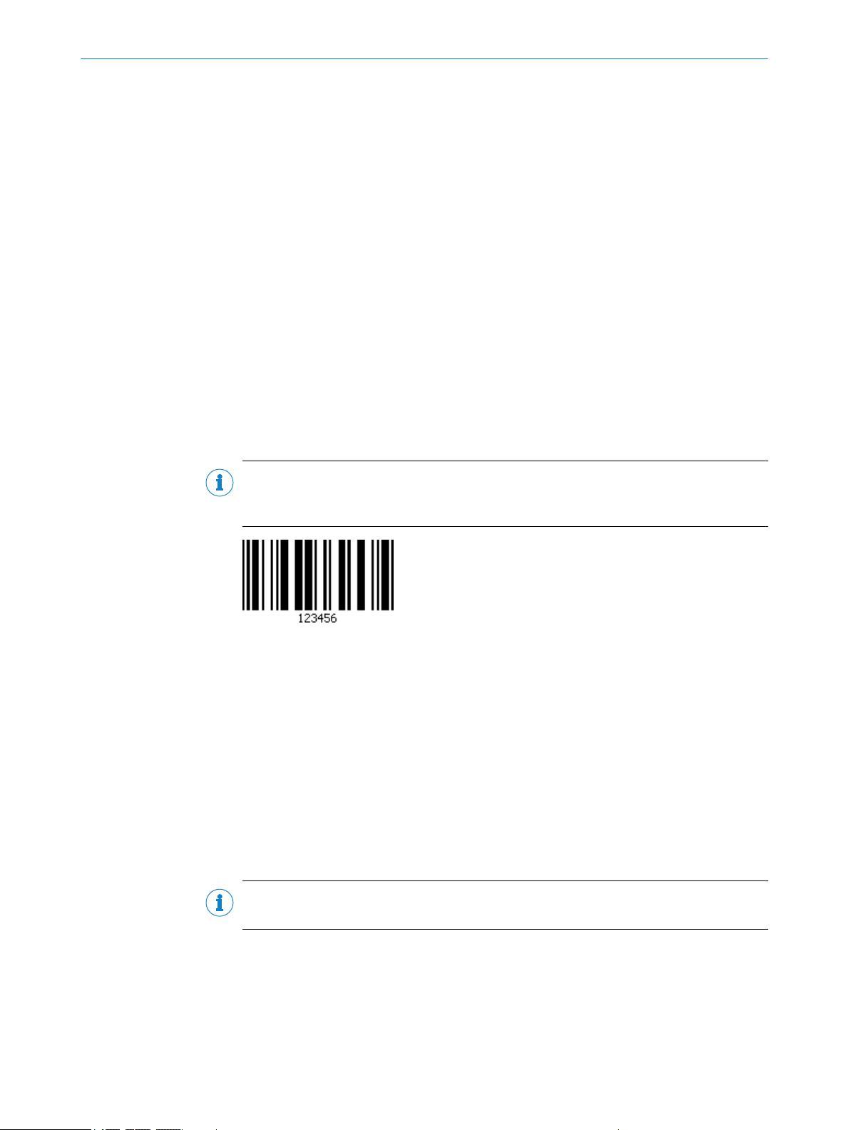
3 2/5 Interleaved
If the 2/5 Interleaved parameter is activated, decoding is activated for the correspond‐
ing code type. The configuration tab for the corresponding code type can be seen and
opened in SOPAS ET.
SOPAS PARAMETER OVERVIEW
NOTE
As only activated code types are processed, you can increase the processing speed by
deactivating the code types that are not being used.
Code name: 2/5 Interleaved or ITF (2-value)
•
Character set: Numeric characters
•
Structure: 5 code elements per character, 2 of which wide and 3 narrow (charac‐
•
ters at odd positions are represented by bars. Characters at even positions are
represented by gaps.)
Intrinsic safety: Low
•
Spatial requirements: Low (up to 18 characters)
•
Standard: ISO/IEC 16390
•
Areas of application: Parcel and postal service
•
4
2D Symbologies
The 2D Symbologies group contains all of the parameters for configuring the 2D code.
NOTE
The fewer code types are activated in parallel, the faster the decoding process.
8013778/YPV6/2016-01-14 | SICK O N L IN E H E LP | Lector62x
Subject to change without notice
13
Page 14
SOPAS PARAMETER OVERVIEW
5 2D Components
If the GS1 DataBar parameter is activated, decoding is activated for the DataBar 14,
DataBar Expanded, and DataBar Limited activated code types. (This requires the GS1
DataBar code type to be deactivated.)
NOTE
As only activated code types are processed, you can increase the processing speed by
deactivating the code types that are not being used.
6 2D Increase Performance
It is possible to optimize the decoding process for 2D codes via the parameters in the
2D Increase Performance group. The parameters can be used to eliminate interference,
thereby increasing device performance.
Adapting the settings to suit the application reduces the decoding time and increases
both reading reliability and the readability of low-contrast, 2D codes.
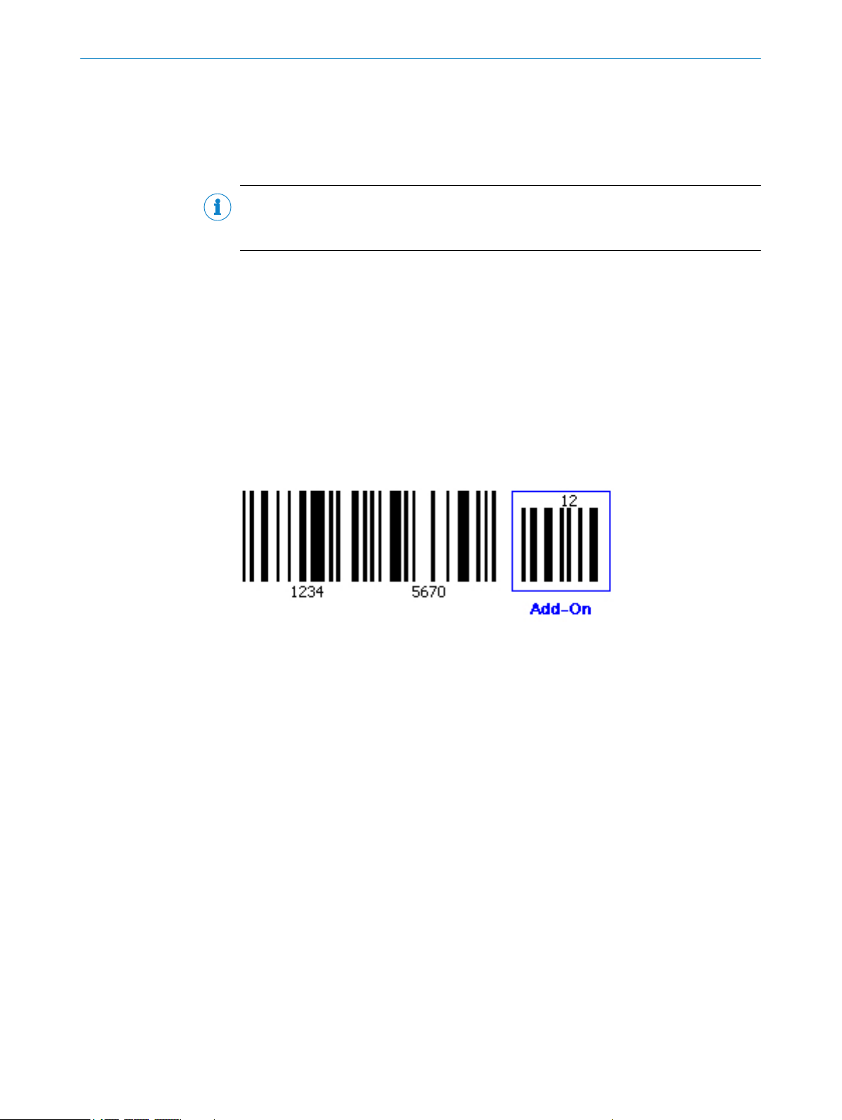
7 Add-on
The Add-on parameter allows you to adjust how the extended code structure is handled
(additional information generally found on magazines).
•
•
•
8 Add-on length
The Add-on length parameter is used to define the length of the extended code struc‐
ture.
•
•
•
NONE: There is no extended code structure available within the code.
ACTIVE: There is an extended code structure available within the code.
REQUIRED: Only codes with an extended code structure are read.
2 CHARACTERS: A 1
5 CHARACTERS: A 1 B 2 C
2 OR 5 CHARACTERS: A 1 or A 1 B 2 C
9 Address
The address of the image server to which the images for the SICK Visualization Platform
are to be sent is specified under the Address parameter.
10 Addressing mode
The Addressing mode parameter is used to specify whether the IP address of the sen‐
sor should be defined manually (STATICALLY) or assigned by a server (DHCP).
14
O NL I NE HE L P | Lector62x 8013778/YPV6/2016-01-14 | SICK
Subject to change without notice
Page 15

11 Active
12 Active
SOPAS PARAMETER OVERVIEW
The data output of the SICK Visualization Platform can be activated via the Active
parameter.
NOTE
The device time must be set to operate the SVP.
The event that activates the digital output is selected via the Active parameter.
SOPAS COMMAND: The output can be activated via a command. This allows defined
•
statuses to be displayed by a connected indicator lamp when a corresponding
command is issued by the control (PLC).
DEVICE READY: The output is activated as soon as the sensor is ready for use.
•
GOOD READ: The output is activated if the read operation was successful.
•
NO READ: The output is activated if the read operation was unsuccessful.
•
TEACH-IN 1 OK: The output is activated if the MATCH CODE TEACH-IN 1 has been success‐
•
fully taught in.
TEACH-IN 1 NOK: The output is activated if the MATCH CODE TEACH-IN 1 could not be suc‐
•
cessfully taught in.
TEACH-IN 2 OK: The output is activated if the MATCH CODE TEACH-IN 2 has been success‐
•
fully taught in.
TEACH-IN 2 NOK: The output is activated if the MATCH CODE TEACH-IN 2 could not be suc‐
•
cessfully taught in.
MATCH 1 CONDITION: The output is activated if the code that has been read corre‐
•
sponds to the MATCH 1 CONDITION match code.
MULTICODES1 CONDITION: The output is activated if the number of codes that have
•
been read corresponds to the number specified by the MULTICODES1 CONDITION.
TEACH-IN1 CONDITION: The output is activated if the code that has been read corre‐
•
sponds to the TEACH-IN1 CONDITION match code.
TEACH-IN2 CONDITION: The output is activated if the code that has been read corre‐
•
sponds to the TEACH-IN2 CONDITION match code.
13
Active Script
Scripts can be activated in the Active Script group.
14 Enable user I/O PDOs
If the Enable user I/O PDOs parameter is activated, user-defined process data objects
(PDOs) can be sent and received by a script program.
The user-defined PDOs are entries in the object directory that are reserved for scripts
and configured in the object directory. The reserved PDOs allow the script to receive
status changes from the CAN input modules and control CAN output modules by send‐
ing a PDO. This is how the communication bandwidth of the device is extended in terms
of its software. The reading device can use the extended communication bandwidth for
control tasks within its surrounding area, even if the required number of switching
inputs and outputs for the control process is not available.
15
8013778/YPV6/2016-01-14 | SICK O N L IN E H E LP | Lector62x
Subject to change without notice
Enable heartbeat
If the Enable heartbeat parameter is activated, a signal is output via the interface at
regular intervals (Heartbeat interval). In this way, the availability of the sensor can be
checked via the interface.
15
Page 16

SOPAS PARAMETER OVERVIEW
16 Activate teach-in mode
Depending on how the Start teach-in parameter has been configured, the Activate
teach-in mode parameter is used to define the signal for preparing or starting the
teach-in process for the match code.
The signal can, for example, originate from a key switch at one of the digital inputs or
be triggered via a command.
NOT DEFINED: The match code is not taught in.
•
SENSOR 1: The match-code teach-in process is prepared and started via a signal at
•
digital input 1 (e.g., a key switch).
SENSOR 2: The match-code teach-in process is prepared and started via a signal at
•
digital input 2.
EXTERNAL INPUT 1 (see note): The match-code teach-in process is prepared and
•
started via a signal at digital external input 1.
EXTERNAL INPUT 2 (see note): The match code teach-in process is prepared and
•
started via a signal on the digital external input 2.
SOPAS COMMAND: The match-code read-in process is prepared and started via a cor‐
•
responding command.
NOTE
The number of available digital inputs can be expanded by using the CDB620/CDM420
connection module in conjunction with the CMC600 parameter memory module. The
purpose of the CMC parameter memory module is to act as an input expansion module
and convert a digital signal into a command. External digital inputs generally respond
more slowly than the internal digital inputs of the sensor.
17
Teach-in stop by
Depending on how the Start teach-in parameter has been configured, the Teach-in stop
by parameter is used to define which signal or condition should terminate the match-
code teach-in process.
TEACH-IN TRIGGER SOURCE: The teach-in process is terminated by a signal (e.g., a key
•
switch) at one of the sensor's digital inputs.
OBJECT TRIGGER: The teach-in process is terminated as soon as the reading gate
•
closes.
VALID CODE TAUGHT IN: The teach-in process is terminated as soon as a match code
•
has been successfully read.
Teach-in Condition
The Teach-in Condition parameter defines the condition that must apply when the newly
taught-in match code content is stored. The selected condition is used as a basis when
the target/actual comparison is activated. Each code that is read is compared to the
code content that was read in for the target condition.
The Teach-in Condition parameter is used to assign the items of code content that are
to be compared to a condition. The taught-in match codes can be retrieved and acti‐
vated at a later time, subject to the condition being met.
Store current counter values now
Pressing the Store current counter values now button saves all values to the device's
flash memory. This means the values remain available without a permanent supply volt‐
age, i.e., the values are still saved after the device is restarted.
16
O NL I NE HE L P | Lector62x 8013778/YPV6/2016-01-14 | SICK
Subject to change without notice
Page 17

18 General Match-code teach-in settings
The General Match-code teach-in settings group contains the parameters for teaching
in the match codes.
The two match codes are stored in the Match-code teach-in 1 and Match-code teach-in
2 (Additional) groups and can be subsequently customized.
19 Alpha
The device's Alpha angle in relation to the code and trigger position is defined under
the Alpha parameter.
Example: Angle set to 90° or 270°. The reading is taken perpendicular to the convey‐
ing direction.
20 Alternate Score
If the Alternate Score parameter is activated, the calculation of the score value is opti‐
mized.
This parameter is used to increase the score values of the Alternate Classifier.
SOPAS PARAMETER OVERVIEW
NOTE
The optimization option is only available for the Alternate Classifier.
21 Change camera settings
If the Change camera settings parameter is activated, the brightness and contrast are
adjusted via the AUTO-SETUP function. This function is accessed by pressing the pushbut‐
tons on the sensor.
22 Change code settings
If the Change code settings parameter is activated, the code settings for the DATA MATRIX
code type are adjusted via the AUTO-SETUP function. This function is accessed by pressing
the pushbuttons on the sensor.
23 Change reading distance
If the Change reading distance parameter is activated, the reading distance is adjusted
via the AUTO-SETUP function. This function is accessed by pressing the pushbuttons on
the sensor.
24 Number of Images
The Number of Images parameter is used to set the number of images that are cap‐
tured in INDIVIDUAL IMAGES capturing mode. The number of images captured depends on
the reading gate length.
25 Number of mapped RPDO bytes
The Number of mapped RPDO bytes parameter defines the scope of the receive proc‐
ess data objects (RPDOs) that can be received by the script program.
8013778/YPV6/2016-01-14 | SICK O N L IN E H E LP | Lector62x
Subject to change without notice
17
Page 18

SOPAS PARAMETER OVERVIEW
26 Number of PDOs
The Number of PDOs parameter is used to determine the number of process data
objects (PDOs) that transmit the reading result.
When reading results are transmitted via PDOs, the reading result data is distributed
across several PDOs. The PDOs are transmitted in sequence. The configured reading
result is restricted to 50 characters for this type of transmission.
27 Number of Attempts
Enter the maximum number of read attempts that are to be made with an activated
parameter set in the event of an automatic parameter switchover under the Number of
Attempts parameter.
28 Application Identifier Marking
If the Application Identifier Marking parameter is activated, the APPLICATION IDENTIFIERS
appear in parentheses in the output format.
On the basis of the APPLICATION IDENTIFIERS, the subsequent values of the code content are
assigned to a defined property. This means that the data contained within a code (e.g.,
use-by date, batch number, date of manufacture, etc.) can be represented in a standar‐
dized format.
29 Application Counters
Events such as successful (GOOD READ) and unsuccessful (NO READ) read operations can
be counted and saved on the Application Counters tab.
Depending on the setting, the device stores the data temporarily in the RAM or perma‐
nently in the flash memory.
Quantitative conditions are defined using counters and can be used for output format‐
ting, for example. Counting functions can be used to control processes, e.g., object bun‐
dling is initiated when a defined counter value is reached.
30 APS/EPS 1
Camera and illumination settings that are used cyclically in the event of automatic or
event-controlled parameter switchover can be made in the APS/EPS 1 to APS/EPS 4
groups.
Pressing the APPLY STANDARD PARAMETERS button applies the parameter settings saved
under the CAMERA AND ILLUMINATION tab.
31 Output Condition
If the Data transmission point parameter is set to the value AS SOON AS POSSIBLE, the Out‐
put Condition parameter can be used to select the data output condition.
GOOD READ: The reading results are output if the read operation was successful.
•
MATCH1 CONDITION: The reading results are output if the code that has been read cor‐
•
responds to the MATCH1 CONDITION match code.
MULTICODES1 CONDITION: The reading results are output if the number of codes that
•
have been read corresponds to the number specified by the MULTICODES1 CONDITION.
TEACH-IN1 CONDITION: The reading results are output if the code that has been read
•
corresponds to the TEACH-IN1 CONDITION match code.
TEACH-IN2 CONDITION: The reading results are output if the code that has been read
•
corresponds to the TEACH-IN2 CONDITION match code.
18
O NL I NE HE L P | Lector62x 8013778/YPV6/2016-01-14 | SICK
Subject to change without notice
Page 19

32 Output Format 1
The format of the data string for outputting the reading results is defined on the graphi‐
cal interface of the Output Format 1 group. A total of two different formats (Output For‐
mat 1 and Output Format 2) can be defined. During configuration of the interfaces,
either of the two output formats can be assigned.
The output format is graphically displayed and can contain conditions, special charac‐
ters (orange), variables (blue), or free text. To customize the output format, select the
required insertion position with the mouse. Use the keyboard or special buttons to
make your entries:
SOPAS PARAMETER OVERVIEW
33
You can use the
tions, special characters (e.g., start and stop), or variables, for example, for the reading
results.
You can use the
tion, you can define which data should be output if the condition is met. You can also
define data in case the condition is not met. Conditions can be interleaved.
To check the output format, you can display the reading results on the terminal. To do
this, open the terminal using the relevant button in the toolbar and establish a con‐
nection with the device (CONNECTION menu on the terminal). For each trigger (reading
gate), a data string is transferred and displayed on the terminal.
Output Format 2
The format of the data string for outputting the reading results is defined on the graphi‐
cal interface of the Output Format 2 group. A total of two different formats (Output For‐
mat 1 and Output Format 2) can be defined. During configuration of the interfaces,
either of the two output formats can be assigned.
The output format is graphically displayed and can contain conditions, special charac‐
ters (orange), variables (blue), or free text. To customize the output format, select the
required insertion position with the mouse. Use the keyboard or special buttons to
make your entries:
button or the context menu (right mouse button) to insert condi‐
button to modify the properties of a condition. For each condi‐
You can use the
button or the context menu (right mouse button) to insert condi‐
tions, special characters (e.g., start and stop), or variables, for example, for the reading
results.
You can use the
button to modify the properties of a condition. For each condi‐
tion, you can define which data should be output if the condition is met. You can also
define data in case the condition is not met. Conditions can be interleaved.
To check the output format, you can display the reading results on the terminal. To do
this, open the terminal using the relevant button in the toolbar and establish a con‐
nection with the device (CONNECTION menu on the terminal). For each trigger (reading
gate), a data string is transferred and displayed on the terminal.
8013778/YPV6/2016-01-14 | SICK O N L IN E H E LP | Lector62x
Subject to change without notice
19
Page 20

SOPAS PARAMETER OVERVIEW
34 Output Format
An output format is assigned to the interface via the Output Format parameter.
NOTE
Output formats are defined under Data processing.
Enable heartbeat
If the Enable heartbeat parameter is activated, what happens at regular intervals
(Heartbeat-Intervall) is that a signal is output via the interface. In this way, the availabil‐
ity of the reading device can be checked via the interface.
Heartbeat interval
The Heartbeat interval parameter is used to define the time between the heartbeat sig‐
nals in seconds.
Restart interval on sending
If the Restart interval on sending parameter is activated, the time between the heart‐
beat signals starts again after the reading results have been output.
35 Output Format
The output format for the interface is selected via the Output Format parameter.
•
•
•
•
36
37
Output Hex-ASCII
If the Output Hex-ASCII parameter is activated, every code character is output as a hex‐
adecimal value. If hexadecimal output has been deactivated via the parameter, the
code content is output directly as ASCII characters. If an ASCII code is output containing
control characters, these are replaced by the @ character to avoid conflicts with the pro‐
tocol framework.
Converting the code content into hexadecimal values enables all characters – including
control characters – to be output.
Output Control
The Output Control group contains the parameters used to determine the timings for
outputting the Output Format 1 and Output Format 2 data.
NO OUTPUT: No data is output via this interface.
OUTPUT FORMAT 1: Data that is output via this interface is formatted in line with the
configuration in the Output Format 1 group.
OUTPUT FORMAT 2: Data that is output via this interface is formatted in line with the
configuration in the Output Format 2 group.
CUSTOMER OUTPUT FORMAT: Via this interface, data is output in a customer-specific for‐
mat. The formatting is defined using the with number parameter.
20
Control system
■
Distance-controlled: If a distance-controlled delay is set, the reading gate only
opens once the object has continued traveling for a predefined distance after the
trigger signal is issued.
■
Time-controlled: If a time-controlled delay is set, the reading gate only opens once
a predefined time has elapsed after the trigger signal is issued.
O NL I NE HE L P | Lector62x 8013778/YPV6/2016-01-14 | SICK
Subject to change without notice
Page 21

38 Output delay
The Output delay parameter allows you to choose between a configuration based on
length units and a configuration based on time units for the Delay, Label Timeout, Con‐
dition Timeout, and Timeout parameters.
DISTANCE-CONTROLLED: The parameter values are entered in mm.
•
TIME-CONTROLLED: The parameter values are entered in ms.
•
39 Data transmission point
You can use the Data transmission point parameter to define when the reading results
are to be output.
END OF READ CYCLE: The reading results of all codes are output as soon as the reading
•
gate is closed. As a result, the data is output at a definable point in time.
AS SOON AS POSSIBLE: The reading results of a code are output as soon as the code
•
has been identified (even if the reading gate is still open). This means that data
can undergo further processing immediately.
NEW CODE: The reading results of a code are output as soon as a code has been
•
identified. However, before the same code can be output again, another code
must first be identified. As a result, you can prevent a code from being identified
multiple times and the data being output again (e.g., during manual reading).
END OF LABEL: The reading results of a code are output as soon as a code leaves the
•
reading area of the sensor.
SOPAS PARAMETER OVERVIEW
In operating mode, image transmission and diagnosis are only available for the END OF
READ CYCLE setting.
40 Output / Result 1
The Output / Result 1 group contains the parameters for adjusting digital output 1.
41 Output / Result 2
The Output / Result 2 group contains the parameters for adjusting digital output 2.
8013778/YPV6/2016-01-14 | SICK O N L IN E H E LP | Lector62x
Subject to change without notice
21
Page 22

SOPAS PARAMETER OVERVIEW
Active
The Active parameter is used to select the event that activates the digital output.
SOPAS COMMAND: The output can be activated via a command. This allows defined
•
statuses to be displayed by a connected indicator lamp when a corresponding
command is issued by the control (PLC).
DEVICE READY: The output is activated as soon as the sensor is ready for use.
•
GOOD READ: The output is activated if the read operation was successful.
•
NO READ: The output is activated if the read operation was unsuccessful.
•
TEACH-IN 1 OK: The output is activated if the MATCH CODE TEACH-IN 1 has been success‐
•
fully taught in.
TEACH-IN 1 NOK: The output is activated if the MATCH CODE TEACH-IN 1 could not be suc‐
•
cessfully taught in.
TEACH-IN 2 OK: The output is activated if the MATCH CODE TEACH-IN 2 has been success‐
•
fully taught in.
TEACH-IN 2 NOK: The output is activated if the MATCH CODE TEACH-IN 2 could not be suc‐
•
cessfully taught in.
EXTERNAL ILLUMINATION: External lighting is connected to the output and can be
•
switched on and off by the device.
MATCH 1 CONDITION: The output is activated if the code that has been read corre‐
•
sponds to the MATCH 1 CONDITION match code.
MULTICODES1 CONDITION: The output is activated if the number of codes that have
•
been read corresponds to the number specified by the MULTICODES1 CONDITION.
TEACH-IN1 CONDITION: The output is activated if the code that has been read corre‐
•
sponds to the TEACH-IN1 CONDITION match code.
TEACH-IN2 CONDITION: The output is activated if the code that has been read corre‐
•
sponds to the TEACH-IN2 CONDITION match code.
NOTE
The behavior of the external illumination and the switch type are set under Illumination.
Inactive
The Inactive parameter is used to select the event that leads to the digital output being
deactivated.
TIMER/TRACKING: The output is deactivated on expiry of a specific period (Length).
•
NEXT OBJECT TRIGGER: The output is deactivated as soon as the next reading gate
•
opens.
SOPAS COMMAND: The output can be deactivated via a command. This allows defined
•
statuses to be displayed by a connected indicator lamp when a corresponding
command is issued by the control (PLC).
GOOD READ: The output is deactivated if the read operation was successful.
•
NO READ: The output is deactivated if the read operation was unsuccessful.
•
TEACH-IN 1START: The output is deactivated as soon as the MATCH CODE TEACH-IN 1 teach-
•
in process commences.
TEACH-IN 2START: The output is deactivated as soon as the MATCH CODE TEACH-IN 2 teach-
•
in process commences.
MATCH 1 CONDITION: The output is deactivated if the code that has been read corre‐
•
sponds to the MATCH 1 CONDITION match code.
MULTICODES1 CONDITION: The output is deactivated if the number of codes that have
•
been read corresponds to the number specified by the MULTICODES1 CONDITION.
TEACH-IN1 CONDITION: The output is deactivated if the code that has been read corre‐
•
sponds to the TEACH-IN1 CONDITION match code.
TEACH-IN2 CONDITION: The output is deactivated if the code that has been read corre‐
•
sponds to the TEACH-IN2 CONDITION match code.
22
O NL I NE HE L P | Lector62x 8013778/YPV6/2016-01-14 | SICK
Subject to change without notice
Page 23

SOPAS PARAMETER OVERVIEW
or
The or parameter can be used to select a second condition for deactivating the digital
output.
In order for the digital output to be deactivated, one of the conditions must be met.
---: No second condition selected
•
MATCH 1 CONDITION: The output is deactivated if the code that has been read corre‐
•
sponds to the MATCH 1 CONDITION match code.
MULTICODES1 CONDITION: The output is deactivated if the number of codes that have
•
been read corresponds to the number specified by the MULTICODES1 CONDITION.
TEACH-IN1 CONDITION: The output is deactivated if the code that has been read corre‐
•
sponds to the TEACH-IN1 CONDITION match code.
TEACH-IN2 CONDITION: The output is deactivated if the code that has been read corre‐
•
sponds to the TEACH-IN2 CONDITION match code.
Logic
The Logik parameter is used to select the polarity of the digital output.
NOT INVERTED: If this option is activated, the digital output switches from Low (0) to
•
High (1).
INVERTED: If this option is activated, the digital output switches from High (1) to Low
•
(0).
Control system
The Control system parameter allows you to choose between a configuration based on
length units and a configuration based on time units.
DISTANCE-CONTROLLED: The values for the Länge parameter are entered in mm.
•
TIME-CONTROLLED: The values for the Länge parameter are entered in ms.
•
Length
If the Inactive parameter is set to the TIMER/TRACKING condition, the Length parameter
can be used to specify how long the digital output should remain activated. The unit
can be selected via the Control system parameter.
42 Output / Result 3
The Output / Result 3 group contains the parameters for adjusting digital output 3.
NOTE
Digital outputs 3 and 4 are not available via the 15-pin D-Sub port on the CDB620 or
CDM420 connection module. They can only be utilized if a 17-pin open-ended cable is
used.
8013778/YPV6/2016-01-14 | SICK O N L IN E H E LP | Lector62x
Subject to change without notice
23
Page 24

SOPAS PARAMETER OVERVIEW
Active
The Active parameter is used to select the event that activates the digital output.
SOPAS COMMAND: The output can be activated via a command. This allows defined
•
statuses to be displayed by a connected indicator lamp when a corresponding
command is issued by the control (PLC).
DEVICE READY: The output is activated as soon as the sensor is ready for use.
•
GOOD READ: The output is activated if the read operation was successful.
•
NO READ: The output is activated if the read operation was unsuccessful.
•
TEACH-IN 1 OK: The output is activated if the MATCH CODE TEACH-IN 1 has been success‐
•
fully taught in.
TEACH-IN 1 NOK: The output is activated if the MATCH CODE TEACH-IN 1 could not be suc‐
•
cessfully taught in.
TEACH-IN 2 OK: The output is activated if the MATCH CODE TEACH-IN 2 has been success‐
•
fully taught in.
TEACH-IN 2 NOK: The output is activated if the MATCH CODE TEACH-IN 2 could not be suc‐
•
cessfully taught in.
EXTERNAL ILLUMINATION: External lighting is connected to the output and can be
•
switched on and off by the device.
MATCH 1 CONDITION: The output is activated if the code that has been read corre‐
•
sponds to the MATCH 1 CONDITION match code.
MULTICODES1 CONDITION: The output is activated if the number of codes that have
•
been read corresponds to the number specified by the MULTICODES1 CONDITION.
TEACH-IN1 CONDITION: The output is activated if the code that has been read corre‐
•
sponds to the TEACH-IN1 CONDITION match code.
TEACH-IN2 CONDITION: The output is activated if the code that has been read corre‐
•
sponds to the TEACH-IN2 CONDITION match code.
Inactive
The Inactive parameter is used to select the event that leads to the digital output being
deactivated.
TIMER/TRACKING: The output is deactivated on expiry of a specific period (Length).
•
NEXT OBJECT TRIGGER: The output is deactivated as soon as the next reading gate
•
opens.
SOPAS COMMAND: The output can be deactivated via a command. This allows defined
•
statuses to be displayed by a connected indicator lamp when a corresponding
command is issued by the control (PLC).
GOOD READ: The output is deactivated if the read operation was successful.
•
NO READ: The output is deactivated if the read operation was unsuccessful.
•
TEACH-IN 1START: The output is deactivated as soon as the MATCH CODE TEACH-IN 1 teach-
•
in process commences.
TEACH-IN 2START: The output is deactivated as soon as the MATCH CODE TEACH-IN 2 teach-
•
in process commences.
MATCH 1 CONDITION: The output is deactivated if the code that has been read corre‐
•
sponds to the MATCH 1 CONDITION match code.
MULTICODES1 CONDITION: The output is deactivated if the number of codes that have
•
been read corresponds to the number specified by the MULTICODES1 CONDITION.
TEACH-IN1 CONDITION: The output is deactivated if the code that has been read corre‐
•
sponds to the TEACH-IN1 CONDITION match code.
TEACH-IN2 CONDITION: The output is deactivated if the code that has been read corre‐
•
sponds to the TEACH-IN2 CONDITION match code.
24
O NL I NE HE L P | Lector62x 8013778/YPV6/2016-01-14 | SICK
Subject to change without notice
Page 25

SOPAS PARAMETER OVERVIEW
or
The or parameter can be used to select a second condition for deactivating the digital
output.
In order for the digital output to be deactivated, one of the conditions must be met.
---: No second condition selected
•
MATCH 1 CONDITION: The output is deactivated if the code that has been read corre‐
•
sponds to the MATCH 1 CONDITION match code.
MULTICODES1 CONDITION: The output is deactivated if the number of codes that have
•
been read corresponds to the number specified by the MULTICODES1 CONDITION.
TEACH-IN1 CONDITION: The output is deactivated if the code that has been read corre‐
•
sponds to the TEACH-IN1 CONDITION match code.
TEACH-IN2 CONDITION: The output is deactivated if the code that has been read corre‐
•
sponds to the TEACH-IN2 CONDITION match code.
Logic
The Logic parameter is used to select the polarity of the digital output.
NOT INVERTED: If this option is activated, the digital output switches from Low (0) to
•
High (1).
INVERTED: If this option is activated, the digital output switches from High (1) to Low
•
(0).
Control system
The Control system parameter allows you to choose between a configuration based on
length units and a configuration based on time units.
DISTANCE-CONTROLLED: The values for the Length parameter are entered in mm.
•
TIME-CONTROLLED: The values for the Length parameter are entered in ms.
•
Length
If the Inactive parameter is set to the TIMER/TRACKING condition, the Length parameter
can be used to specify how long the digital output should remain activated. The unit
can be selected via the Control system parameter.
43 Output / Result 4
The Output / Result 4 group contains the parameters for adjusting digital output 4.
NOTE
Digital outputs 3 and 4 are not available via the 15-pin D-Sub port on the CDB620 or
CDM420 connection module. They can only be utilized if a 17-pin open-ended cable is
used.
8013778/YPV6/2016-01-14 | SICK O N L IN E H E LP | Lector62x
Subject to change without notice
25
Page 26

SOPAS PARAMETER OVERVIEW
Active
The Active parameter is used to select the event that activates the digital output.
SOPAS COMMAND: The output can be activated via a command. This allows defined
•
statuses to be displayed by a connected indicator lamp when a corresponding
command is issued by the control (PLC).
DEVICE READY: The output is activated as soon as the sensor is ready for use.
•
GOOD READ: The output is activated if the read operation was successful.
•
NO READ: The output is activated if the read operation was unsuccessful.
•
TEACH-IN 1 OK: The output is activated if the MATCH CODE TEACH-IN 1 has been success‐
•
fully taught in.
TEACH-IN 1 NOK: The output is activated if the MATCH CODE TEACH-IN 1 could not be suc‐
•
cessfully taught in.
TEACH-IN 2 OK: The output is activated if the MATCH CODE TEACH-IN 2 has been success‐
•
fully taught in.
TEACH-IN 2 NOK: The output is activated if the MATCH CODE TEACH-IN 2 could not be suc‐
•
cessfully taught in.
MATCH 1 CONDITION: The output is activated if the code that has been read corre‐
•
sponds to the MATCH 1 CONDITION match code.
MULTICODES1 CONDITION: The output is activated if the number of codes that have
•
been read corresponds to the number specified by the MULTICODES1 CONDITION.
TEACH-IN1 CONDITION: The output is activated if the code that has been read corre‐
•
sponds to the TEACH-IN1 CONDITION match code.
TEACH-IN2 CONDITION: The output is activated if the code that has been read corre‐
•
sponds to the TEACH-IN2 CONDITION match code.
Inactive
The Inactive parameter is used to select the event that leads to the digital output being
deactivated.
TIMER/TRACKING: The output is deactivated on expiry of a specific period (see
•
"Length", page 84).
NEXT OBJECT TRIGGER: The output is deactivated as soon as the next reading gate
•
opens.
SOPAS COMMAND: The output can be deactivated via a command. This allows defined
•
statuses to be displayed by a connected indicator lamp when a corresponding
command is issued by the control (PLC).
GOOD READ: The output is deactivated if the read operation was successful.
•
NO READ: The output is deactivated if the read operation was unsuccessful.
•
TEACH-IN 1START: The output is deactivated as soon as the MATCH CODE TEACH-IN 1 teach-
•
in process commences.
TEACH-IN 2START: The output is deactivated as soon as the MATCH CODE TEACH-IN 2 teach-
•
in process commences.
MATCH 1 CONDITION: The output is deactivated if the code that has been read corre‐
•
sponds to the MATCH 1 CONDITION match code.
MULTICODES1 CONDITION: The output is deactivated if the number of codes that have
•
been read corresponds to the number specified by the MULTICODES1 CONDITION.
TEACH-IN1 CONDITION: The output is deactivated if the code that has been read corre‐
•
sponds to the TEACH-IN1 CONDITION match code.
TEACH-IN2 CONDITION: The output is deactivated if the code that has been read corre‐
•
sponds to the TEACH-IN2 CONDITION match code.
26
O NL I NE HE L P | Lector62x 8013778/YPV6/2016-01-14 | SICK
Subject to change without notice
Page 27

SOPAS PARAMETER OVERVIEW
or
The or parameter can be used to select a second condition for deactivating the digital
output.
In order for the digital output to be deactivated, one of the conditions must be met.
---: No second condition selected
•
MATCH 1 CONDITION: The output is deactivated if the code that has been read corre‐
•
sponds to the MATCH 1 CONDITION match code.
MULTICODES1 CONDITION: The output is deactivated if the number of codes that have
•
been read corresponds to the number specified by the MULTICODES1 CONDITION.
TEACH-IN1 CONDITION: The output is deactivated if the code that has been read corre‐
•
sponds to the TEACH-IN1 CONDITION match code.
TEACH-IN2 CONDITION: The output is deactivated if the code that has been read corre‐
•
sponds to the TEACH-IN2 CONDITION match code.
Logic
The Logic parameter is used to select the polarity of the digital output.
NOT INVERTED: If this option is activated, the digital output switches from Low (0) to
•
High (1).
INVERTED: If this option is activated, the digital output switches from High (1) to Low
•
(0).
Control system
The Control system parameter allows you to choose between a configuration based on
length units and a configuration based on time units.
DISTANCE-CONTROLLED: The values for the Länge parameter are entered in mm.
•
TIME-CONTROLLED: The values for the Länge parameter are entered in ms.
•
Length
If the Inactive parameter is set to the TIMER/TRACKING condition, the Length parameter
can be used to specify how long the digital output should remain activated. The unit
can be selected via the Control system parameter.
44 Evaluation Conditions
Conditions that are checked by the device at each reading gate are defined in the Eval‐
uation Conditions group. If defined conditions are fulfilled, specific actions can be per‐
formed by the device – for example, setting an output signal, ending a reading gate, or
outputting an image or a particular data string.
Evaluation conditions can be used to define situations that serve as reference points in
the device software for flexible process control and data processing. The use of evalua‐
tion conditions shifts the complexity of control tasks from the external controls (PLCs)
into the code reader, meaning costs are reduced.
8013778/YPV6/2016-01-14 | SICK O N L IN E H E LP | Lector62x
Subject to change without notice
27
Page 28
SOPAS PARAMETER OVERVIEW
General operation
Conditions that have already been created can be edited via the button. A dialog
box opens which specifies the condition in detail.
Conditions that have been taught in can be deleted via the button.
Another new condition can be created via the
allows you to specify the condition precisely. The condition type and name are precisely
defined in the dialog box along with the condition itself.
45 Auto
Pressing the Auto button starts the Auto-Setup wizard for automatic adjustment of the
reading distance.
In order for the reading distance to be adjusted automatically, a suitable object with
contrast variations or edges (e.g., code, text, or other structures) must be placed in the
reading area.
NOTE
The reading distance can only be adjusted automatically if there is a certain back‐
ground brightness to ensure the structures in the image are visible.
46 Automatic Tuning / Parameter Switchover
The parameter switchover switches over the saved parameter sets during the reading
interval. A maximum of four different parameter sets can be saved in the parameter
switchover.
If codes are to be read on different background materials or under different application
conditions, the parameter switchover can be used. The individual parameter sets can
be adapted individually and optimally to the respective code or the application. This
increases the flexibility and stability of the sensor.
button. A dialog box opens which
47
28
Automatic Tuning
Image optimization can be activated and configured in the Automatic Tuning group dur‐
ing operation.
The brightness tuning is ideally used if code contrasts fluctuate or ambient lighting con‐
ditions change slightly. It is recommended that brightness tuning is only carried out
when the system is stationary due to the time required for the brightness measurement
and adjustment.
O NL I NE HE L P | Lector62x 8013778/YPV6/2016-01-14 | SICK
Subject to change without notice
Page 29

48 Auto-Setup via function button menu
The Auto-Setup via function button menu group contains the parameters for adjusting
the Auto-Setup wizards.
The AUTO-SETUP function is divided into three individual modules:
READING DISTANCE
•
IMAGE SETTINGS (brightness and contrast)
•
CODE SETTINGS (only available for DATA MATRIX for the time being)
•
The AUTO-SETUP function can be started in different ways:
Via wizard
•
Via pushbuttons on sensor
•
By pressing the AUTO buttons
•
Via command (SOPAS command)
•
Commands for starting the AUTO-SETUP function:
SMN MASSTART: The Auto-Setup process is started.
•
SMN MASFINISH: The Auto-Setup process is stopped and the result is applied. To
•
return to reading mode, you must end the Auto-Setup process with a stop com‐
mand.
SMN MASCANCEL: The Auto-Setup process is stopped. This does, however, cause the
•
result to be discarded. To return to reading mode, you must end the Auto-Setup
process with a stop command.
SOPAS PARAMETER OVERVIEW
NOTE
Even if you start the AUTO-SETUP function via a command, the settings for the wizard
(standard or advanced) are still taken into consideration. The settings can also be con‐
figured using commands. A detailed list of commands can be obtained from SICK on
request.
49 Barcode Symbology
The Barcode Symbology parameter determines which barcode symbology is used to
enter the received data in the sensor. The selected barcode symbology must also be
enabled in the sensor.
For the USE FIRST CHARACTER FOR IDENTIFICATION setting, the first character after the Rx
Header must correspond to the code ID for the required bar code.
Examples:
STX > E 123456 ETX: Input via code ID "e" as 2/5 Interleaved, content = 123456
•
STX > B ABCDEF ETX: Input via code ID "b" as code 39, content = abcdef
•
NOTE
For a list of valid bar code IDs, see Code-IDs für Barcodes
8013778/YPV6/2016-01-14 | SICK O N L IN E H E LP | Lector62x
Subject to change without notice
29
Page 30

SOPAS PARAMETER OVERVIEW
Code IDs for bar codes
a, CODABAR
•
b, CODE39
•
c, UPC
•
d, EAN
•
e, INTERLEAVED25
•
g, MSI CODE
•
i, CODE93
•
j, CODE128
•
l, PLESSY
•
n, EAN 128
•
o, PHARMA
•
p, GS1 DataBar Expanded
•
r, PDF417
•
s, QR CODE
•
t, TELEPEN
•
u, GS1 DataBar Limited
•
w, MAXICODE
•
y, GS1_DATABAR
•
z, AZTEC
•
<, CODE32 (6 digit C39 decodes as C32)
•
50 Base COB-ID for ReadResult PDOs
The Base COB-ID for ReadResult PDOs parameter defines the CAN identifier of the first
transmit process data object (TPDO), which used to transmit the reading result.
When reading results are transmitted via process data objects (PDOs), the reading
result is distributed across several PDOs that are sent to the PLC one after the other.
The identifier for the first PDO must be configured; subsequent PDOs have consecutive
identifiers.
51 Baud rate
The maximum transmission rate for data sent by the sensor to the host can be adjusted
via the Baud rate parameter.
The value is specified in baud. This value defines the number of signal changes that
can take place via the interface per second. Depending on the protocol, up to four bits
can be transmitted per signal change (e.g., with 2,400 baud: up to 9,600 bits/second).
52 Baud rate
The maximum transmission rate can be adjusted via the Baud rate parameter.
The value is specified in bits/s.
NOTE
All devices on the CAN network must run at the same data baud rate. The maximum
length of cable for the network is dependent on the baud rate.
30
O NL I NE HE L P | Lector62x 8013778/YPV6/2016-01-14 | SICK
Subject to change without notice
Page 31

53 Condition for image storing
The Condition for image storing parameter is used to select the condition that must be
met for images to be stored for diagnostic purposes.
GOOD READ: Only images resulting from a successful code reading operation are
•
stored.
NO READ: Only images resulting from an unsuccessful code reading operation are
•
stored.
ALL: All captured images are stored.
•
MATCH 1 CONDITION: The captured images are only stored if the code that has been
•
read corresponds to the MATCH 1 CONDITION match code.
MULTICODES1 CONDITION: The captured images are only stored if the number of codes
•
that have been read corresponds to the number specified by the MULTICODES1 CONDI‐
TION.
TEACH-IN1 CONDITION: The captured images are only stored if the Match-code teach-in
•
1 condition is met.
TEACH-IN2 CONDITION: The captured images are only stored if the Match-code teach-in
•
2 (Additional) condition is met.
54 Condition for Good Read
SOPAS PARAMETER OVERVIEW
The Condition for Good Read list box is used to define the condition that must be met in
order for a read operation to be evaluated as "good" (GOOD READ).
•
•
•
•
•
55 Invert condition
A condition can be inverted using the Invert condition parameter. Inverting a condition
allows all code content to be approved except the taught-in match code content.
With this function, it is possible to prevent a particular product from leaving the produc‐
tion line.
USE MIN./MAX. NUMBER OF CODES: Depending on how the Check min. number of valid
codes and Check max. number of valid codes parameters are configured, a read
operation is evaluated as "good" (GOOD READ) if the number of codes read falls
between the minimum and maximum values specified.
MATCH1 CONDITION: The read operation is evaluated as "good" (GOOD READ) if the code
that has been read corresponds to MATCH CODE MATCH 1.
MULTICODES1 CONDITION: The read operation is evaluated as "good" (GOOD READ) if the
number of codes that have been read corresponds to the specified number.
TEACH-IN1 CONDITION: The read operation is evaluated as "good" (GOOD READ) if the
code that has been read corresponds to MATCH CODE TEACH-IN 1.
TEACH-IN2 CONDITION: The read operation is evaluated as "good" (GOOD READ) if the
code that has been read corresponds to MATCH CODE TEACH-IN 2.
8013778/YPV6/2016-01-14 | SICK O N L IN E H E LP | Lector62x
Subject to change without notice
31
Page 32

SOPAS PARAMETER OVERVIEW
56 Usage of Input Data
The Usage of Input Data parameter is used to define how the sensor uses data
received at the serial host interface.
NO INPUT DATA: No data is received at the interface.
•
DATA STRING FORWARDING: The incoming data is forwarded to another interface. Possi‐
•
ble destination interfaces are serial auxiliary, serial host, Ethernet auxiliary, and
Ethernet host.
AUXILIARY INPUT: The incoming data is output to all configured interfaces in the same
•
way as an internal reading result.
EDS TEXT ELEMENT IN OUTPUT FORMAT: The incoming data is assigned to the EDS variable,
•
which can be used in the output string.
NOTE
For further details and settings, see External Input Data.
57 Illumination
The parameters in the Illumination group are used to switch the illumination elements
on or off as well as to adjust them.
By optimizing the settings, you can create a high-contrast reading field that is con‐
stantly illuminated. In this way, external influences – such as sunlight, darkness, room
illumination, etc. – can be minimized.
58 Shutter time
The Shutter time parameter is used to define the time frame for capturing an image in
µs. The shutter time can be set via the slide control.
A short shutter time can accommodate high object speeds. As this causes the
•
image brightness to decrease, it may be necessary to adjust the signal amplifica‐
tion (Brightness). This does, however, increase the image noise.
A long shutter time offers a high level of brightness and, therefore, minimal image
•
noise. This is the optimal setting for stationary or slow-moving objects.
59
User Name
A user name for the FTP image transfer to the SICK Visualization Platform is specified
under the User Name parameter.
60 Activate Calculation
Code evaluation based on various standards can be activated in the Activate Calcula‐
tion group.
32
NOTE
The results of the code evaluation sensor are not ISO standardized values. As the sen‐
sor is not a standardized verifier, the process is deemed 'code evaluation' rather than
verification.
O NL I NE HE L P | Lector62x 8013778/YPV6/2016-01-14 | SICK
Subject to change without notice
Page 33

61 certain numb. of new labels
If the value NEW CODE is selected for the Data transmission point parameter, the certain
numb. of new labels parameter can be used to define the minimum number of codes
that must be read before a code is output again. This prevents the same object from
being read multiple times.
62 Beta
The device's Beta angle in relation to the trigger position is defined under the Beta
parameter.
63 Operation
If you press the Operation button, the mode for setting up the sensor is stopped, and
the operating mode of the sensor is activated in accordance with the current configura‐
tion.
NOTE
Image sequence displays the captured images one after the other. The reading results
are displayed in the Code info box. The reading results for the last readings are com‐
bined in the display fields for the Statistics group.
SOPAS PARAMETER OVERVIEW
So that the current contrast setting can be evaluated, the identified codes are dis‐
played in different colors:
•
•
•
64 Operating Data
Various items of operating information are recorded for the device under Operating
Data.
•
•
•
65 Operating mode
The Operating mode parameter is used to select a data transmission mode.
•
•
•
Green (excellent): Contrast between 55% and 100%
Yellow (good): Contrast between 20% and 55%
Red (poor): Contrast less than 20%
POWER-ON COUNTER: Displays how many times the device has been switched on.
OPERATING HOURS: Displays the total number of device operating hours.
POWER-ON TIME: Displays the current number of operating hours since the last
switch-on.
MODE1: CMF STANDARD FORMAT / BYTE HANDSHAKE / DIGITAL IO: In this transmission mode,
telegram acknowledgment ensures that no telegrams are lost. This mode is rec‐
ommended for high object frequencies and long telegrams.
MODE2: CMF STANDARD FORMAT / NO BYTE HANDSHAKE / DIGITAL IO: In this transmission
mode, no telegrams are acknowledged. It is possible to lose telegrams if the PLC
cycle time is too slow. The mode should only be used for low object frequencies
and short telegrams.
MODE3: BMV-COMPATIBLE / NO DIGITAL IO: The mode is compatible with BMV/H10-0111.
The mode should only be selected if it is necessary to replace a BMV/H.
NOTE
Some parameter values are not supported by all device types.
8013778/YPV6/2016-01-14 | SICK O N L IN E H E LP | Lector62x
Subject to change without notice
33
Page 34

SOPAS PARAMETER OVERVIEW
66 Image Capturing Mode
Two image capturing processes are available under the Image Capturing Mode parame‐
ter:
CONTINUOUS: Continuous image capturing by the sensor at the set image frequency.
•
If the image frequency was not set manually, images are captured at 25 or 60 Hz
depending on the device type.
INDIVIDUAL IMAGES: Only the number of images set under the NUMBER OF IMAGES param‐
•
eter are captured regardless of the reading interval length.
The CONTINUOUS image capturing mode is the default setting and suitable for most appli‐
cations. It is recommended that INDIVIDUAL IMAGES capturing mode is used for fast appli‐
cations with small gaps between objects. The decoding time is considerably reduced
due to the limited number of images captured.
67 Image output dominant over trigger
The Image output dominant over trigger parameter defines a processing sequence for
outputting images and accepting an object trigger. If this parameter is activated, the
diagnostic images are transmitted in full before the device accepts and processes the
object trigger for the subsequent reading process. If this parameter is deactivated, a
trigger signal is processed by the device anyway and any image output operation that
has not yet been completed is interrupted.
For the purpose of editing the reading device, image output can be prioritized to deter‐
mine what the device detects within a reading gate. If this parameter is activated, you
can check the object trigger interval and length of the reading process. We only recom‐
mend prioritizing the image output for normal operation in exceptional circumstances in
the case of applications where image output is more important than continuous object/
code detection.
68 Image region of interest
The Image region of interest parameter allows you to focus the reading field on the rele‐
vant areas.
Reducing the size of the reading field makes the decoding time shorter and increases
the frame rate. This enables faster object speeds to be achieved.
NOTE
To change the size of the reading field, adjust the red marking by dragging and drop‐
ping or by entering the four % values.
34
O NL I NE HE L P | Lector62x 8013778/YPV6/2016-01-14 | SICK
Subject to change without notice
Page 35

69 Image selection
The Image selection parameter is used to select the images that are to be stored for
each reading gate.
LAST GOOD READ / LAST IMAGE: Following a successful code reading operation, the sys‐
•
tem stores the last image from which one or more codes have been read. If the
code reading operation was unsuccessful, the most recently captured image is
stored. (This is recommended for applications where the code does not move out
of the reading gate during reading.)
FIRST IMAGE: The system stores the first image captured in each case. (This is recom‐
•
mended for applications where the code moves during reading and the code acts
as a trigger, i.e., the first image already contains a code.)
IMAGE SEQUENCE: All captured images are stored as a sequence. (This is recom‐
•
mended for applications where the reading gate is opened by an object and the
position of the code on the object is not precisely known.) Image sequences can
be captured to carry out a triggering check and to verify the quality of the shots in
the case of moving objects. The images are numbered in the top left-hand corner.
If any image numbers are missing, it means that not all the shots could be
decoded and so the settings (e.g., code settings) must be adjusted accordingly.
70 Image rotation 180°
SOPAS PARAMETER OVERVIEW
If the Image rotation 180° parameter is activated, the image is rotated 180° when it is
captured.
Given that images are always processed from top to bottom, codes that are located
toward the top of the image get detected earlier. Rotating the image 180° reduces the
decoding time for codes that are not positioned centrally. This is particularly applicable
when reading stationary objects.
71 Image settings
The image brightness and contrast settings are made via the parameters in the Image
settings group.
A good image that displays the code clearly is essential for a reliable reading. Optimiza‐
tion of the image settings results in better code identification and, in turn, increases the
reliability of the reading.
72 Copy images
The images stored in the sensor or on the microSD memory card are transferred to the
PC via the Copy images button.
You can select any storage location on the PC.
Delete images
You can use the Bilder löschen button to remove the data (images, .xml files, etc.)
stored in the sensor or on the microSD memory card.
Load image(s)
You can use the Load image(s) button to display the images that have been transferred
previously.
8013778/YPV6/2016-01-14 | SICK O N L IN E H E LP | Lector62x
Subject to change without notice
35
Page 36

SOPAS PARAMETER OVERVIEW
73 Save Images
If the Save Images parameter is activated, the images recorded by the sensor are
stored on a separate image server.
74 Image filter
The Image filter group contains parameters for optimizing the camera image in the
case of noise or special code markings.
75 Set frame rate manually
If the Set frame rate manually parameter is activated, the frame rate (image frequency)
can be specified by the user. If this parameter is deactivated, the reading device oper‐
ates at the maximum frame rate. The REQUEST button can be used to retrieve the current
frame rate of a connected device. There may be a discrepancy between the frame rate
set and the actual frame rate used by the reading device. The device adjusts the frame
rate in line with other settings, such as the shutter time. A long shutter time reduces
the frame rate significantly.
It makes sense to reduce the frame rate for slow applications where the object contain‐
ing the code moves past the reading device slowly. Reducing the frame rate increases
the time for evaluating individual images. This results in increased reading reliability for
each individual image. A lower frame rate is not suitable for fast applications, as you
run the risk of not detecting the code on any image.
76 Image file name
The Image file name parameter can be used to specify the name for the image files.
The image files also contain a consecutive number and, if the Good Read / No Read file
prefix parameter is activated, a name prefix is included as well (GOOD READ or NO READ).
Assigning appropriate file names makes it possible to identify the image files clearly
(e.g., by attributing them to a particular project/device).
77 Image quality
The Image quality parameter can be used to adjust the file size/quality (resolution) of
the stored image files. This setting does not affect the reading speed of the sensor.
An xml file containing the Code info box data is stored for each image.
•
•
•
•
•
•
Quality level 6 (maximum resolution): File size for full image region of interest 354
KB
Quality level 5: File size for full image region of interest 90 KB
Quality level 4: File size for full image region of interest 41 KB
Quality level 3: File size for full image region of interest 24 KB
Quality level 2: File size for full image region of interest 16 KB
Quality level 1: File size for full image region of interest 12 KB
36
O NL I NE HE L P | Lector62x 8013778/YPV6/2016-01-14 | SICK
Subject to change without notice
Page 37

78 Image sequence
Image sequence displays the captured images one after the other. The images that
were captured last are inserted on the left.
By comparing and evaluating the images that have been captured, it is possible to ana‐
lyze (for example):
•
•
•
NOTE
In order to determine the cause of unsuccessful read operations, it can sometimes be
helpful to analyze the images containing codes that could not be identified (NO READ).
Click on the smaller images in the Image sequence to display them in the main view.
The file names and storage locations of images are displayed in a tooltip (mouseover).
SOPAS PARAMETER OVERVIEW
Whether the trigger has been set correctly and the appropriate section of the read‐
ing field has been captured
Whether the codes on moving objects have been captured in focus and whether
the shutter time has been set correctly
How often a code was captured per reading gate
You can use the and buttons to switch between multiple sequences.
The number of images displayed depends on the operating mode and the configura‐
tion:
Depending on how the Image selection parameter is configured, either the last
•
200 individual images (one image per trigger) or sets of 60 images per second are
displayed in individual sequences.
During the reading process for testing the configuration (Setup operating mode),
•
the system shows the last 30 images captured.
8013778/YPV6/2016-01-14 | SICK O N L IN E H E LP | Lector62x
Subject to change without notice
37
Page 38

SOPAS PARAMETER OVERVIEW
79 C32 conversion
If the C32 conversion parameter is activated, decoding is enabled for the relevant code
type.
NOTE
As only activated code types are processed, the processing speed can be increased by
specifically activating/deactivating the necessary code types.
Code name: C32 conversion (two-value)
•
Character set: 32 alphanumeric characters (upper-case letters A to Z, digits 0 to 9,
•
no special characters)
Structure: Leading quiet zone, start character, useful character, check character,
•
stop character, trailing quiet zone (13 to 16 modules per character)
Intrinsic safety: High
•
Spatial requirements: Variable symbol length
•
Standard: ISO/IEC 16388, ANSI/AIM BC5 1995
•
Areas of application: Part numbers for pharmaceutical products (Italian Pharma‐
•
code), packaging for human medicines
80
CAN
The CAN interface is configured on the CAN tab.
81 CAN Open Heartbeat Time / ms
The see "CAN Open Heartbeat Time / ms", page 38 parameter defines the time interval
between the CANopen heartbeat objects in ms.
The heartbeat protocol is used on CANopen networks to check the CAN nodes. The
CANopen heartbeat protocol stipulates that every CAN node must send out heartbeat
objects at cyclical intervals and receive them from other bus participants. The transmis‐
sion cycle must be configured.
38
O NL I NE HE L P | Lector62x 8013778/YPV6/2016-01-14 | SICK
Subject to change without notice
Page 39

82 CANopen Receive PDOs 1 .. 4
The process data objects (PDOs) received by the device are configured in the CANopen
Receive PDOs 1 .. 4 group. The values entered must correspond to the CANopen speci‐
fication.
PREDEF. CONN.: A Yes value indicates that the Predefined Connection Set identifiers
•
defined by the CANopen specification should be used. The configured COB identifi‐
ers are ignored.
MAP OBJ.1-8: Up to eight objects can be mapped for each TPDO. If the number of
•
mapping objects specified is lower, the last entries in the table are ignored.
NOTE
The values entered are not validated via the SOPAS ET user interface. If invalid or incon‐
sistent values have been entered, an incorrect entry is created during PDO initialization.
83 CANopen Transmit PDOs 1 .. 4
The process data objects (PDOs) sent by the device are configured in the CANopen
Transmit PDOs 1 .. 4 group. The values entered must correspond to the CANopen speci‐
fication.
SOPAS PARAMETER OVERVIEW
84 Classifier
PREDEF. CONN.: A Yes value indicates that the Predefined Connection Set identifiers
•
defined by the CANopen specification should be used. The configured COB identifi‐
ers are ignored.
MAP OBJ.1-8: Up to eight objects can be mapped for each TPDO. If the number of
•
mapping objects specified is lower, the last entries in the table are ignored.
NOTE
The values entered are not validated via the SOPAS ET user interface. If invalid or incon‐
sistent values have been entered, an incorrect entry is created during PDO initialization.
The Classifier parameter determines which algorithm the sensor uses to optimize rec‐
ognition. The Classifier algorithm defines the type of character recognition and charac‐
ter comparison with the taught-in characters.
ALTERNATE: The Alternate algorithm is an optimized algorithm that improves the
•
reading rate but reduces the score value.
STANDARD: The Standard algorithm is suitable for applications in which the print
•
quality is paramount. Stricter criteria are used to determine the score values out‐
put.
NOTE
It is recommended to use the Alternate Classifier to ensure a more stable reading.
85 COB-ID Emergency Obj.
The COB-ID Emergency Obj. parameter defines the CAN identifier for emergency objects
in the CANopen protocol.
The CANopen protocol requires emergency objects to transmit error codes. The error
codes are defined in communication profile DS-301 and in device profile DSP-40x.
8013778/YPV6/2016-01-14 | SICK O N L IN E H E LP | Lector62x
Subject to change without notice
39
Page 40

SOPAS PARAMETER OVERVIEW
86 COB-ID RPDO user Dig. Input
The COB-ID RPDO user Dig. Input parameter defines the CAN identifier for the userdefined receive process data objects (RPDOs) received on the reading device.
For the first four receive process data objects (RPDOs), communication and mapping
can be configured by accessing objects 0x1400 to 0x1403 and 0x1600 to 0x1603.
The configuration is saved in the device's parameter set. The other RPDOs cannot be
configured.
87 COB-ID RPDO Dig. Input
The COB-ID RPDO Dig. Input parameter defines the CAN identifier for the receive proc‐
ess data objects (RPDOs) received on the reading device.
88 COB-ID TPDO user Dig. Output
The COB-ID TPDO user Dig. Output parameter defines the CAN identifier for the userdefined transmit process data objects (TPDOs) sent by the reading device.
89 COB-ID TPDO Dig. Output
The COB-ID TPDO Dig. Output parameter defines the CAN identifier for the transmit
process data objects (TPDOs) sent by the reading device.
For the first four transmit process data objects (TPDOs), communication and mapping
can be configured by accessing objects 0x1800 to 0x1803 and 0x1A00 to 0x1A03.
This task is normally performed by a CANopen control. The configuration is saved in the
device's parameter set.
Objects TPDO6 to TPDO12 are used to output the reading result and cannot be config‐
ured.
NOTE
It is recommended to use TPDO2 to TPDO4 for user-defined applications. Object TPDO1
is used for synchronization. TPDO1 is used to signal the availability of data that can be
retrieved by the service data object client (SDO client) via an SDO upload access.
40
O NL I NE HE L P | Lector62x 8013778/YPV6/2016-01-14 | SICK
Subject to change without notice
Page 41

90 Codabar
SOPAS PARAMETER OVERVIEW
If the Codabar parameter is activated, decoding is activated for the corresponding code
type. The configuration tab for the corresponding code type can be seen and opened in
SOPAS ET.
NOTE
As only activated code types are processed, you can increase the processing speed by
deactivating the code types that are not being used.
Code name: Codabar (two-value)
•
Character set: 16 alphanumeric characters (10 digits, 6 special characters)
•
Structure: 7 code elements (4 bars, 3 gaps); start character (A, B, C, or D), code
•
content, stop character (A, B, C, or D)
Intrinsic safety: Low
•
Spatial requirements: Variable
•
Areas of application: Parcel and postal service
•
Standard: EN 798 bar coding
•
91 Code 128
If the Code 128 parameter is activated, decoding is enabled for the relevant code type.
(This requires the Code 128 code type to be deactivated.)
NOTE
As only activated code types are processed, the processing speed can be increased by
specifically activating/deactivating the necessary code types.
Code name: Code 128 (4-value)
•
Character set: Alphanumeric (ASCII) with three switchable character sets and one
•
check digit
Character set A: Digits, upper-case letters, special characters, and ASCII con‐
°
trol characters
Character set B: Digits, upper-case and lower-case letters, special characters,
°
and escape characters
Character set C: 100 pairs of digits (00 to 99) and FNC1 special character
°
Structure: Start symbol, useful information, check digit, stop symbol (11 modules
•
per symbol, each with 3 bars and 3 gaps)
Intrinsic safety: Very high (self-checking: even number of bars, uneven number of
•
gaps)
Spatial requirements: Largest possible number of characters per centimeter
•
Standard: ISO/IEC 15420
•
Areas of application: All areas, as UCC 128/EAN 128 in retail
•
8013778/YPV6/2016-01-14 | SICK O N L IN E H E LP | Lector62x
Subject to change without notice
41
Page 42

SOPAS PARAMETER OVERVIEW
92 Code 128 Family
If the Code 128 Family parameter is activated, decoding is enabled for the activated
Code 128 and EAN 128 code types at the same time. (This requires the Pharmacode
code type to be deactivated.) The configuration tab for the corresponding code types
can be seen and opened in SOPAS ET.
NOTE
As only activated code types are processed, you can increase the processing speed by
deactivating the code types that are not being used.
93 Code 39
If the Code 39 parameter is activated, decoding is enabled for the relevant code type.
NOTE
As only activated code types are processed, the processing speed can be increased by
specifically activating/deactivating the necessary code types.
94 Code 93
Code name: Code 39 (two-value)
•
Character set: 43 alphanumeric characters (10 digits, 26 letters, 7 special charac‐
•
ters)
Structure: 9 code elements (5 bars, 4 gaps) – 3 wide and 6 narrow
•
Intrinsic safety: Average
•
Spatial requirements: High
•
Standard: ISO/IEC 16388
•
Areas of application: Parcel and postal service
•
If the Code 93 parameter is activated, decoding is enabled for the relevant code type.
NOTE
As only activated code types are processed, the processing speed can be increased by
specifically activating/deactivating the necessary code types.
Code name: Code 93 (4-value)
•
Character set: 43 alphanumeric characters (10 digits, 26 upper-case letters, 7
•
special characters: space, -, ., $, /, +, and %)
Intrinsic safety: Average
•
Spatial requirements: Low
•
Standard: ISO/IEC 16388
•
Areas of application: Parcel and postal service
•
42
O NL I NE HE L P | Lector62x 8013778/YPV6/2016-01-14 | SICK
Subject to change without notice
Page 43

95 Code appearance
The decoding process can be limited to mirrored or non-mirrored codes using the Code
appearance parameter, which reduces the decoding time.
NORMAL: Only non-mirrored codes can be decoded correctly.
•
MIRRORED: Only mirrored codes that have been captured from below through a glass
•
pane, for example, can be decoded correctly. This involves reversing the images
that have been captured by mirroring them again before they are decoded.
BOTH: Both mirrored and non-mirrored codes are read.
•
SOPAS PARAMETER OVERVIEW
96
Code distance
97 Code format
The Code distance parameter is used to define the minimum distance for distinguish‐
ing between identical codes.
In this case, the system only distinguishes between codes of the same type and with
identical content if the distance between them on the object is equal to or greater than
the specified Code distance.
The Code format parameter is used to select the format (Data Matrix code symbology)
for outputting data:
ECC200: The data is output in the standard data format.
•
GS1: The data is output in the special GS1 data format. User-specific characters
•
can be defined for the FNC1 character (control character at the start of the code)
and for the separator (control character within the code). This means, for example,
that a line break (CR, LF) can be inserted in the data string after each APPLICATION
IDENTIFIER.
98
8013778/YPV6/2016-01-14 | SICK O N L IN E H E LP | Lector62x
Subject to change without notice
Code background
The decoding process can be limited to codes with a light or dark background color
using the Code background parameter, which reduces the decoding time.
WHITE: Only dark codes on a light background are read.
•
BLACK: Only light codes on a dark background (inverted codes) are read.
•
BOTH: Both dark codes on a light background and light codes on a dark background
•
(inverted codes) are read.
43
Page 44

SOPAS PARAMETER OVERVIEW
99 Code info box
The reading results are displayed in the Code info box. So that the readability and read
quality can be evaluated, the code content is displayed along with other relevant data
for all detected codes. Codes that have been detected multiple times in one image are
listed one below the other.
NOTE
The columns can be enlarged and their sequence changed using drag and drop.
CODE CONTENT
The content of the codes is displayed in the CODE CONTENT column.
The fact that the code content is matched to the code means you can compare the con‐
tent that has been read with the actual content of the code.
CODE ID
The code type is displayed in the CODE ID column. The process of assigning the code
type to the code content allows you to activate/deactivate certain code types in the
code configuration in order to limit multiple content to one code type, for example.
CODE CONTRAST PCS
100
The contrast of the codes is displayed in % in the CODE CONTRAST PCS column.
A high contrast makes it easier to identify a code. By comparing different configura‐
tions, you can find the setting for the highest possible contrast.
From 55% to 100%: Contrast EXCELLENT
•
From 20% to 55%: Contrast GOOD
•
Less than 20%: Contrast POOR
•
MODULE WIDTH/HEIGHT IN PX
The module width and height of the codes is displayed in pixels in the MODULE WIDTH/
HEIGHT IN PX column.
The value can be used to evaluate the reading reliability (reserve) in relation to the
image resolution. The higher the value, the more reliable the reading. A value of at least
2/2 is recommended, i.e., every code element is represented by at least 2/2 pixels.
By comparing the two values, you can detect any distortion of the image or of the code.
The module width is the dimension of the smallest code element (bar of a bar
•
code or cell in a Data Matrix code) in pixels.
The module height is the length of a bar in a bar code or the height of a cell in a
•
Data Matrix code.
Code configuration
The parameters on the Code configuration tab allow you to make decoding settings for
individual code types. The code types are each assigned to a code structure.
44
NOTE
As only activated code types are processed, you can increase the processing speed by
deactivating the code types that are not being used.
O NL I NE HE L P | Lector62x 8013778/YPV6/2016-01-14 | SICK
Subject to change without notice
Page 45

101 Code configuration
The Code configuration parameter allows you to specify whether the teach-in process
for a match code should affect the current code configuration, and if so, how.
DO NOT CHANGE: The process of teaching in a match code does not change the cur‐
•
rent code configuration. The system can carry on reading all the configured code
types.
LIMIT TO THE CODE LAST TAUGHT IN: The code configuration is adjusted in line with the
•
match code that has been taught in. This means that the parameters for the code
type, the code length, and the code content are restricted to the match code prop‐
erties. As a result, the system can only read codes that conform to the match
code.
EXPAND WITH THE CODE LAST TAUGHT IN: The code configuration is adjusted in line with the
•
match code that has been taught in by activating the parameters for this new
match code as well. As all the other code settings remain unchanged, the system
can carry on reading all the configured code types.
102 Code contrast
To find the codes in the reading field, the captured image is searched thoroughly for
structures with sufficiently large contrast variations. A code pattern is only expected
within these structures.
SOPAS PARAMETER OVERVIEW
103 Code length
A minimum value for these contrast variations is defined in % via the Code contrast
parameter. The system does not search for code patterns in areas where the contrast is
below the defined value.
So that low-contrast codes can still be read reliably, a low value (e.g., 10%) must
•
be set. This does, however, increase the decoding time, as it involves searching a
larger image area.
For high-contrast codes, the value can be increased accordingly. In this case, a
•
correspondingly smaller image area is searched, which reduces the decoding time.
The Code length parameter can be used to restrict the number of characters allowed
within a code.
FREE: Codes of any code length are read.
•
INTERVAL: The Interval parameter can be used to define the minimum and maximum
•
code length. Codes are only read if their length falls between these two values.
FIXED: The Fixed Codelengths parameter can be used to define several fixed code
•
lengths. Codes are only read if they feature one of these defined code lengths.
8013778/YPV6/2016-01-14 | SICK O N L IN E H E LP | Lector62x
Subject to change without notice
45
Page 46

SOPAS PARAMETER OVERVIEW
104 Code Quality
The code evaluation settings are made on the Code Quality tab. Code evaluations
based on various standards can be used to compare and check reading results from
different sensors.
105 Separate codes depending on position
If the Separate codes depending on position parameter is activated, codes of the same
type and with identical content are distinguished from one another according to their
position on the object.
For this to take place, there must be a definable minimum distance (Code distance)
between the identical codes on the object.
106 Label timeout active
If the Label timeout active parameter is activated, you can define how much time has to
elapse before an identical code may be output again.
107 Code surrounded by patterns
If the Code surrounded by patterns parameter is activated, any lines (e.g., printed con‐
ductors on a PCB) around the code are disregarded during evaluation.
This keeps the reading operation focused on the code elements and reduces the
decoding time.
NOTE
When the function is activated, poor quality codes tend to be ignored.
46
O NL I NE HE L P | Lector62x 8013778/YPV6/2016-01-14 | SICK
Subject to change without notice
Page 47

108 Code surrounded by text
If the see "Code surrounded by text", page 47 parameter is activated, any text (e.g., on
packaging) around the code is disregarded during evaluation.
This keeps the reading operation focused on the code elements and reduces the
decoding time.
NOTE
When the function is activated, poor quality codes tend to be ignored.
SOPAS PARAMETER OVERVIEW
109 DataBar 14
If the DataBar 14 parameter is activated, decoding is enabled for the relevant code
type.
NOTE
As only activated code types are processed, you can increase the processing speed by
deactivating the code types that are not being used.
Code name: DataBar 14
•
Character set: 14 fixed digits
•
Structure: 94 modules divided into 46 elements; code words consist of 15 or 16
•
modules and are represented by 4 gaps and 4 lines; the finder pattern has 14
modules; the lines and gaps are shown with 8 different module widths, i.e., the
elements can be between 1X and 8X wide
Intrinsic safety: High
•
Standard: ISO/IEC 2427
•
Areas of application: Trade
•
8013778/YPV6/2016-01-14 | SICK O N L IN E H E LP | Lector62x
Subject to change without notice
47
Page 48

SOPAS PARAMETER OVERVIEW
110 DataBar Expanded
If the DataBar Expanded parameter is activated, decoding is enabled for the relevant
code type.
NOTE
As only activated code types are processed, you can increase the processing speed by
deactivating the code types that are not being used.
Code name: GS1 DataBar Expanded (GDBE)
•
Character set: Max. 74 digits, max. 41 characters
•
Structure: 2 guard patterns: 2 modules each, both containing 1 bar and 1 gap;
•
4-22 data characters: 17 modules each, all containing 4 bars and 4 gaps; 2-11
finder patterns and 1 check digit
Intrinsic safety: High
•
Spatial requirements: Variable
•
Standard: ISO/IEC 646
•
Areas of application: Variable-measure foods, coupons
•
111
DataBar Limited
If the DataBar Limited parameter is activated, decoding is enabled for the relevant code
type.
NOTE
As only activated code types are processed, you can increase the processing speed by
deactivating the code types that are not being used.
•
•
•
•
•
•
•
Code name: GS1 DataBar Limited (GDBL)
Character set: 14 fixed digits
Structure: No quiet zone, the separator consists of a gap (1X) and a line (1X)
Intrinsic safety: High
Spatial requirements: Low
Standard: ISO/IEC 24727
Areas of application: Trade and industry (pharmaceuticals industry and electronics
sector)
48
O NL I NE HE L P | Lector62x 8013778/YPV6/2016-01-14 | SICK
Subject to change without notice
Page 49

112 Data Matrix
SOPAS PARAMETER OVERVIEW
If the Data Matrix parameter is activated, decoding is activated for the corresponding
code type. The configuration tab for the corresponding code type can be seen and
opened in SOPAS ET.
As only activated code types are processed, you can increase the processing speed by
deactivating the code types that are not being used.
Code name: Data Matrix
•
Max. number of numeric characters: 3,116
•
Max. number of alphanumeric characters: 2,335
•
Max. number of ASCII characters: 1,982
•
Max. number of ISO characters: 1,556
•
Structure: Symbol with L-pattern, rectangular symbols also possible
•
Standard: ISO/IEC 16022
•
Areas of application: Electronics, automotive, aviation, pharmaceuticals, and food
•
packaging
113 File Format
The file format can be configured in the File Format group.
114 File name
The File name parameter can be used to specify a file name for the log file.
115 File Path
The structure of the data storage can be specified under File Path.
116 Data output mode
The Data output mode parameter is used to define how often data is output.
SINGLE: The reading results are output once.
•
MULTIPLE: Initially, the reading results are output once. On expiry of a specific period
•
(Label Timeout or Condition Timeout), the data is output again. If the appropriate
setting is made, it is possible to distinguish between different objects with identi‐
cal codes.
117 Data bits / parity
The Data bits / parity parameter is used to define the number of data bits (8 or 7) and
the corresponding parity. The setting must match the one on the host.
118 Collection of data
Data is assigned to an object in the Collection of data group. Using the parameters in
the Collection of data group, object data can be uniquely set in relation to a particular
object and the code content can be uniquely assigned to an object.
8013778/YPV6/2016-01-14 | SICK O N L IN E H E LP | Lector62x
Subject to change without notice
49
Page 50

SOPAS PARAMETER OVERVIEW
Timeout
The Timeout parameter defines how much time has to elapse before data processing is
started or stopped.
119 Data Source
Select an interface to be recorded in the Data Source group.
120 Data processing
The Data processing tab contains the parameters for defining the two output formats,
as well as for filtering, sorting, and controlling data output.
These parameters are used to define what data is output on the communication inter‐
faces, as well as when, under what conditions, and in what order.
121 Data String Forwarding
This option can be used if you intend to send data from an external device such as a
hand-held scanner to a host in addition to the reading result. In this case, the data is
not interpreted by the sensor, but is also output at the specified interface. The digital
outputs are not controlled and the data is not processed according to evaluation condi‐
tions.
Possible destinations are:
Serial aux interface
•
Serial host interface
•
Ethernet aux interface
•
Ethernet host interface
•
122 Date (YYYY-MM-DD)
The Date (YYYY-MM-DD) parameter is used to enter the date that the reading device
should apply when setting its device time. Device time synchronization is triggered by
the user via the SET DEVICE TIME button.
123 Date
If the Date parameter is activated, a subfolder is created with the creation date.
124 Duration
The Duration parameter is used to define the time frame for the optical feedback
(Green feedback spot).
125 Decoding
The Decoding parameter defines whether the read operation should be time-optimized
or whether it is more important to adopt an aggressive decoding approach.
50
FAST: Fast decoding is recommended if the code is of high quality and it is impor‐
•
tant to achieve a short decoding time.
AGGRESSIVE: The Aggressive option should be selected when the decoding time is
•
less relevant, e.g., when reading a stationary object, but the code is of lower qual‐
ity (e.g., low levels of contrast or when the code contains an error).
BALANCED: The Balanced option accommodates applications that fall between the
•
two extremes.
O NL I NE HE L P | Lector62x 8013778/YPV6/2016-01-14 | SICK
Subject to change without notice
Page 51

126 Default Gateway
The default gateway address is defined manually via the Default Gateway parameter.
The default gateway redirects all network activity that does not belong to this subnet‐
work to another subnetwork.
127 Default Data String
The Default Data String parameter is used to define a default text for the EDS variable.
The default text is output for EDS whenever no valid data has been received during the
reading interval.
The EDS variable is described using the default data string at the start of the reading
interval. During the reading interval, the EDS variable can be overwritten by an external
device with the required data – several times, if necessary. At the end, the most
recently assigned value or the default data string is output.
In order for data to be output, the EDS variable (object-related, EDS = external data
string) must be inserted in the output format. By double-clicking, you have the option to
format the EDS variable, e.g., by setting a fixed length.
128 DeviceNet-Gateway
SOPAS PARAMETER OVERVIEW
The DeviceNet-Gateway group contains the parameters for DeviceNet settings.
129 DHCP
If the DHCP parameter is activated, a DHCP server from the corporate network auto‐
matically provides the gateway with an IP address, subnet mask, and default gateway
address. The addresses do not have to be entered manually.
130 DHCP Fallback Mode
The DHCP Fallback Mode parameter is used to select an action that is performed if
automatic IP assignment was not possible.
STATIC IP: A static IP value is set as soon as it is established that DHCP was not pos‐
•
sible.
REPEAT DHCP: The process is repeated until an IP is assigned via DHCP.
•
131 Image Diagnosis Settings
The Image Diagnosis Settings tab is used to define which images are transmitted or
stored by the reading device for diagnostic purposes. It is even possible to define time
delays and the conditions for transmitting or saving the images.
The file path, storage medium, and image names can also be defined.
One of the purposes of saving images is to support the user during the commissioning
process by making it clear what the device is detecting. A further function of saving
images is to help with device analysis in the event of a failed read operation (reading
result: NO READ). The stored images make it easy to identify potential causes of failure
such as the deterioration of code markings.
8013778/YPV6/2016-01-14 | SICK O N L IN E H E LP | Lector62x
Subject to change without notice
51
Page 52

SOPAS PARAMETER OVERVIEW
132 Log File Diagnosis Settings
Using the Log File Diagnosis Settings parameter, reading results from different interfa‐
ces can be written to the internal memory or the micro SD card.
This function enables the reading results to be recorded without an external PC so that
they can be evaluated later.
133 Digital Outputs / Beeper
The Digital Outputs / Beeper tab contains all of the parameters for configuring the digi‐
tal outputs.
These parameters define which events cause an output signal to be sent.
NOTE
The required output signal function must be configured accordingly in another area. If,
for example, you want to use output signals as application counters, you must make the
relevant settings on the Application Counters tab.
134 Digital Inputs
The Digital Inputs tab contains all of the parameters for configuring the digital inputs.
These parameters define the signal that causes the input to respond, along with the
associated time delay.
NOTE
The required input signal function must be configured accordingly in another area. If,
for example, you want to use input signals as object triggers, you must make the rele‐
vant settings on the Object Trigger Control tab.
52
O NL I NE HE L P | Lector62x 8013778/YPV6/2016-01-14 | SICK
Subject to change without notice
Page 53

135 Dot size
SOPAS PARAMETER OVERVIEW
The Dot size parameter expands the code elements optically so that the sensor can be
adjusted to cope with poorly legible codes (e.g., codes with gaps between the dots of
the L-pattern).
: Poorly legible
: Perfectly legible
If the codes have been produced using ink-jet printers, dot peening machines, or lasers
(for example), the code elements may not be joined together seamlessly. In this case,
the readability of the codes can be improved by expanding the code elements.
136 EAN 128
NOTE
The value should be increased in stages until the code can be read successfully.
If the EAN 128 parameter is activated, decoding is enabled for the relevant code type.
(This requires the Pharmacode code type to be deactivated.)
NOTE
As only activated code types are processed, the processing speed can be increased by
specifically activating/deactivating the necessary code types.
Code name: EAN 128 (4-value)
•
Character set: Alphanumeric (ASCII) with three switchable character sets
•
Character set A: Digits, upper-case letters, and special characters
°
Character set B: Digits, upper-case and lower-case letters
°
Character set C: Double-density digits
°
Structure: FNC1, characters, check digit
•
Intrinsic safety: High
•
Spatial requirements: Low
•
Standard: ISO/IEC 15417
•
Areas of application: Identification of durable consumer goods
•
8013778/YPV6/2016-01-14 | SICK O N L IN E H E LP | Lector62x
Subject to change without notice
53
Page 54

SOPAS PARAMETER OVERVIEW
Multiread
The Multiread parameter is used to define the minimum number of successful read
operations (GOOD READS) required in order for the GOOD READ result to be output.
Defining a minimum number of read operations reduces the likelihood of codes being
misinterpreted if the print quality is poor or the contrast is low. At the same time, it
increases the reading reliability.
137
EAN
138 Setup
The GTIN 8 / EAN 8 and GTIN 13 / EAN 13 code types can be activated or deactivated
under the EAN group.
Pressing the Setup button starts the reading process for testing the configuration. Dur‐
ing this process, images are captured in free-running mode and displayed in the main
view.
Changes to the configuration (e.g., image settings or code configuration) or the position
of the sensor (e.g., reading distance or angle) are immediately visible in the main view.
This makes it possible to complete test readings, as well as to check and optimize the
current position and configuration of the sensor.
So that the current contrast setting can be evaluated, the identified codes are dis‐
played in different colors:
Green (excellent): Contrast between 55% and 100%
•
Yellow (good): Contrast between 20% and 55%
•
Red (poor): Contrast less than 20%
•
Behavior of the sensor during editing:
Images are integrated into the image sequence at a rate of one per second so that
•
changes can be recorded.
So that the current contrast setting can be evaluated, the identified codes are dis‐
•
played in different colors.
The code content and other relevant data are displayed in the code info box for all
•
detected codes so that the reading stability can be assessed.
The reading results are transferred to the AUX interface in the configured output
•
format.
The reading results are not transferred to the host interface.
•
External triggers at the digital inputs are ignored.
•
Trigger distribution on the CAN interface is deactivated.
•
No digital outputs are set.
•
139
Emcy Inhibit Time
140 Sensitivity
54
O NL I NE HE L P | Lector62x 8013778/YPV6/2016-01-14 | SICK
The Emcy Inhibit Time parameter defines the interval that must elapse between the
repeated transmission of emergency objects in ms.
The Sensitivity parameter allows you to choose between edge control and level control.
EDGE: The digital input responds to the switch between Low (0) and High (1)
•
according to how the Logic parameter is configured. Any signal that is permanently
present is ignored.
LEVEL: The digital input responds to a permanently present signal according to how
•
the Logic parameter is configured.
Subject to change without notice
Page 55

141 Enable Diagnosis Output
If the Enable Diagnosis Output parameter is activated, the device's reading diagnosis
data is monitored by the control via the CANopen interface. The reading device initiates
monitoring via process data objects (PDOs). The device sends a PDO with identifier
0x180 and details of the CAN node to indicate that the control should load an entry.
142 Enable Command Response
If the Enable Command Response parameter is activated, the reading device responds
to the SOPAS commands sent by the PLC.
SOPAS commands from the control are entered into object 0x2200/0. The reading
device responds via an entry in object 0x2020/4 and sends a process data object
(PDO) with identifier 0x180 and the CAN node number to the PLC. The PLC loads the
command response entered in the object directory via the SDO domain.
SOPAS commands constitute a command language that can be used to control the
functions of the reading device and the object trigger control. A detailed list of the com‐
mands can be obtained from SICK on request.
143 Debouncing
SOPAS PARAMETER OVERVIEW
Depending on how the Control system parameter is configured, the Debouncing param‐
eter specifies the minimum distance in mm or the minimum time in ms for the signal at
the external input. If the value is not achieved, the signal is not detected.
Depending on the application, this value may have to be adapted in line with the read
cycle rates required.
144 EPS Source
Specify the interface at which an event-based parameter switchover is triggered under
the EPS Source parameter.
145 Number of Lines Detected
The Number of Lines Detected parameter outputs the number of lines that have been
detected.
The value may change if the NUMBER OF LINES EXPECTED parameter has been changed. If all
the lines have been correctly identified in a stable manner, the values for the number of
lines expected and detected will be the same.
146 Allowed code types
You can use the Allowed code types parameter to define which code types should be
read in as a match code.
Any code could be interpreted as a Pharmacode, even if it actually had a different code
type. Therefore, the Pharmacode type must be selected exclusively.
ACTIVATED CODE TYPES: All the activated code types are accepted for the purpose of
•
teaching in the match code in accordance with the code configuration. To ensure
that the required code type can be read, the code configuration must first be
checked.
ALL (EXCEPT PHARMACODE): All code types are accepted for the purpose of teaching in
•
the match code, apart from the Pharmacode type.
PHARMA ONLY: Only codes of the Pharmacode type are accepted for the purpose of
•
teaching in the match code.
8013778/YPV6/2016-01-14 | SICK O N L IN E H E LP | Lector62x
Subject to change without notice
55
Page 56

SOPAS PARAMETER OVERVIEW
147 Allowed Characters / Scoring
A character filter can be used to limit the number of characters to be read and a scor‐
ing system activated in the Allowed Characters / Scoring group.
Setting the character filter limits the number of characters to be detected for the
selected character position. When the filter is set, the stability and accuracy of the
reading is increased and the reading time is reduced. Depending on the font used, the
character “1” is similar to the characters “I” and “J”. “F” is similar to “P” and “C” is simi‐
lar to “G”.
The scoring system specifies how identical the detected character is to the taught-in - or
ideal - character. The maximum value is 100.
148 Allowed Character 1
This parameter is used to define allowed characters for a character position by setting a
character filter in the field at the desired position.
Character filter:
? – ALL CHARACTERS: All characters are expected and detected by the sensor at this
•
position.
$ – ONLY A-Z: Only upper-case letters of the Latin alphabet are expected and
•
detected by the sensor at this position.
* – ONLY A-Z: Only lower-case letters of the Latin alphabet are expected and detected
•
by the sensor at this position.
# – ONLY NUMBERS: Only numbers are expected and detected by the sensor at this
•
position.
% – ONLY SPECIAL CHARACTERS: Only special characters are expected and detected by
•
the sensor at this position.
& – ONLY A-Z + NUMBERS: Only upper-case letters of the Latin alphabet and numbers
•
are expected and detected by the sensor at this position.
A - CHARACTER TO BE READ (E.G., A): The sensor only expects and detects the character
•
specified in the field at this position.
NOTE
If a filter is only set for numbers, for example, letters will not be accepted when teach‐
ing in is subsequently carried out.
149 Calculated Speed
The current speed is indicated in the Calculated Speed display field.
For this to happen, a connection must be established between the sensor and the PC.
150 FNC1 Character Replacement
In the GS1 code format, the FNC1 Character Replacement parameter can be used to
define user-specific characters for the FNC1 character (control character at the start of
the code).
The characters are entered via the keyboard or clipboard.
It is possible to select special characters or enter hexadecimal characters via the
symbol.
Information on editing the characters is available via the symbol.
56
O NL I NE HE L P | Lector62x 8013778/YPV6/2016-01-14 | SICK
Subject to change without notice
Page 57

151 Separator Character Replacement
In the GS1 code format, the Separator Character Replacement parameter can be used
to define user-specific characters for the separator (control character within the code).
The characters are entered via the keyboard or clipboard.
It is possible to select special characters or enter hexadecimal characters via the
symbol.
Information on editing the characters is available via the symbol.
SOPAS PARAMETER OVERVIEW
152
Expected Number of Characters 1
This parameter can be used to determine the number of expected characters in a line.
The number of expected characters must be specified. The algorithm uses this value to
optimize the search for characters.
153 Number of Lines Expected
The Number of Lines Expected parameter determines the number of lines in the image
expected by the sensor.
The number of expected lines must be specified. The algorithm uses this value to opti‐
mize the search for lines of text.
154 EtherNet/IP
Device communication via Ethernet/IP can be activated and configured on the Ether‐
Net/IP tab.
155 EtherNet/IP enabled
Device communication via Ethernet/IP is activated/deactivated via the EtherNet/IP
enabled parameter. Once Ethernet/IP has been activated, the reading device must be
restarted.
156 Ethernet
The Ethernet tab contains all of the parameters for configuring the Ethernet interface.
The device address and the configuration data for the host and aux ports can be
entered on the tab.
157 Ethernet General
The Ethernet General group contains general parameters for configuring the Ethernet
interfaces (host and aux).
158 Ethernet Aux
If the Ethernet Aux parameter is activated, the results from the Ethernet aux interface
are written to the save destination.
8013778/YPV6/2016-01-14 | SICK O N L IN E H E LP | Lector62x
Subject to change without notice
57
Page 58

SOPAS PARAMETER OVERVIEW
159 Ethernet Aux Port
The Ethernet Aux Port group contains the parameters for configuring the Ethernet aux
interface. The Ethernet aux interface is typically used for configuring and analyzing the
sensor.
Output Format
The Output Format parameter is used to select the output format for the interface.
NO OUTPUT: No data is output via this interface.
•
READING DIAGNOSIS: This interface is used to output a diagnosis string for each read‐
•
ing gate.
OUTPUT FORMAT 1: Data that is output via this interface is formatted in line with the
•
configuration in the Output Format 1 group.
OUTPUT FORMAT 2: Data that is output via this interface is formatted in line with the
•
configuration in the Output Format 2 group.
For the reading diagnosis, the following information is combined in a diagnosis string
for each reading gate:
TT: Reading gate duration in ms
•
OTL: Trigger length in mm
•
CC: No. of codes per reading gate
•
FC: Focal position in mm
•
Code content
•
Code type
•
For 1D Symbologies
CL: Code length
•
RSD1DV: Ratio of scans to decoded scans (reading reliability) in %
•
For 2D Symbologies
SZ: Symbol size
•
RES: Cell resolution in pixels
•
CTV: Symbol contrast in %
•
UECV: Decodability (unused error correction) in %
•
MC: Number of multireads per code
•
Server / Client
The Server / Client parameter is permanently set to the CLIENT value and cannot be
changed.
IP port
The IP-Port parameter can be used to adjust the port number for the Ethernet aux inter‐
face (default value: 2111) in line with the connected PC or control (PLC).
160 Ethernet Host
If the Ethernet Host parameter is activated, the results from the Ethernet host interface
are written to the save destination.
161 Ethernet Host Port
58
The Ethernet Host Port group contains the parameters for configuring the Ethernet host
interface. The Ethernet host interface is typically used for communication with the con‐
trol.
O NL I NE HE L P | Lector62x 8013778/YPV6/2016-01-14 | SICK
Subject to change without notice
Page 59

SOPAS PARAMETER OVERVIEW
Output Format
The Output Format parameter is used to select the output format for the interface.
NO OUTPUT: No data is output via this interface.
•
OUTPUT FORMAT 1: Data that is output via this interface is formatted in line with the
•
configuration in the Output Format 1 group.
OUTPUT FORMAT 2: Data that is output via this interface is formatted in line with the
•
configuration in the Output Format 2 group.
162
Event Monitor
Input signals and output signals are represented graphically in the Event Monitor group.
The signal visualization function allows you to test events such as output triggering or
switching and to check the logic and function of signal sequences.
163 External Output 1
The number of available digital outputs can be expanded by using the CDB620/
CDM420 connection module in conjunction with the CMC600 parameter memory mod‐
ule. The purpose of the CMC parameter memory module is to act as an output expan‐
sion module and convert a digital signal into a command. External digital outputs gen‐
erally respond more slowly than the internal digital outputs of the sensor.
The External Output 1 group contains the parameters for adjusting external digital out‐
put 1.
ACTIVE
The Active parameter is used to select the event that activates the digital output.
SOPAS COMMAND: The output can be activated via a command. This allows defined
•
statuses to be displayed by a connected indicator lamp when a corresponding
command is issued by the control (PLC).
DEVICE READY: The output is activated as soon as the sensor is ready for use.
•
GOOD READ: The output is activated if the read operation was successful.
•
NO READ: The output is activated if the read operation was unsuccessful.
•
TEACH-IN 1 OK: The output is activated if the MATCH CODE TEACH-IN 1 has been success‐
•
fully taught in.
TEACH-IN 1 NOK: The output is activated if the MATCH CODE TEACH-IN 1 could not be suc‐
•
cessfully taught in.
TEACH-IN 2 OK: The output is activated if the MATCH CODE TEACH-IN 2 has been success‐
•
fully taught in.
TEACH-IN 2 NOK: The output is activated if the MATCH CODE TEACH-IN 2 could not be suc‐
•
cessfully taught in.
MATCH 1 CONDITION: The output is activated if the code that has been read corre‐
•
sponds to the MATCH 1 CONDITION match code.
MULTICODES1 CONDITION: The output is activated if the number of codes that have
•
been read corresponds to the number specified by the MULTICODES1 CONDITION.
TEACH-IN1 CONDITION: The output is activated if the code that has been read corre‐
•
sponds to the TEACH-IN1 CONDITION match code.
TEACH-IN2 CONDITION: The output is activated if the code that has been read corre‐
•
sponds to the TEACH-IN2 CONDITION match code.
8013778/YPV6/2016-01-14 | SICK O N L IN E H E LP | Lector62x
Subject to change without notice
59
Page 60

SOPAS PARAMETER OVERVIEW
Inactive
The Inactive parameter is used to select the event that leads to the digital output being
deactivated.
TIMER/TRACKING: The output is deactivated on expiry of a specific period (Length).
•
NEXT OBJECT TRIGGER: The output is deactivated as soon as the next reading gate
•
opens.
SOPAS COMMAND: The output can be deactivated via a command. This allows defined
•
statuses to be displayed by a connected indicator lamp when a corresponding
command is issued by the control (PLC).
GOOD READ: The output is deactivated if the read operation was successful.
•
NO READ: The output is deactivated if the read operation was unsuccessful.
•
TEACH-IN 1START: The output is deactivated as soon as the MATCH CODE TEACH-IN 1 teach-
•
in process commences.
TEACH-IN 2START: The output is deactivated as soon as the MATCH CODE TEACH-IN 2 teach-
•
in process commences.
MATCH 1 CONDITION: The output is deactivated if the code that has been read corre‐
•
sponds to the MATCH 1 CONDITION match code.
MULTICODES1 CONDITION: The output is deactivated if the number of codes that have
•
been read corresponds to the number specified by the MULTICODES1 CONDITION.
TEACH-IN1 CONDITION: The output is deactivated if the code that has been read corre‐
•
sponds to the TEACH-IN1 CONDITION match code.
TEACH-IN2 CONDITION: The output is deactivated if the code that has been read corre‐
•
sponds to the TEACH-IN2 CONDITION match code.
or
The or parameter can be used to select a second condition for deactivating the digital
output.
In order for the digital output to be deactivated, one of the conditions must be met.
---: No second condition selected
•
MATCH 1 CONDITION: The output is deactivated if the code that has been read corre‐
•
sponds to the MATCH 1 CONDITION match code.
MULTICODES1 CONDITION: The output is deactivated if the number of codes that have
•
been read corresponds to the number specified by the MULTICODES1 CONDITION.
TEACH-IN1 CONDITION: The output is deactivated if the code that has been read corre‐
•
sponds to the TEACH-IN1 CONDITION match code.
TEACH-IN2 CONDITION: The output is deactivated if the code that has been read corre‐
•
sponds to the TEACH-IN2 CONDITION match code.
Logic
The Logic parameter is used to select the polarity of the digital output.
NOT INVERTED: If this option is activated, the digital output switches from Low (0) to
•
High (1).
INVERTED: If this option is activated, the digital output switches from High (1) to Low
•
(0).
Control system
60
The Control system parameter allows you to choose between a configuration based on
length units and a configuration based on time units.
DISTANCE-CONTROLLED: The values for the Length parameter are entered in mm.
•
TIME-CONTROLLED: The values for the Length parameter are entered in ms.
•
O NL I NE HE L P | Lector62x 8013778/YPV6/2016-01-14 | SICK
Subject to change without notice
Page 61

Length
If the Inactive parameter is set to the TIMER/TRACKING condition, the Length parameter
can be used to specify how long the digital output should remain activated. The unit
can be selected via the Control system parameter.
164 EXTERNAL OUTPUT 2
The number of available digital outputs can be expanded by using the CDB620/
CDM420 connection module in conjunction with the CMC600 parameter memory mod‐
ule. The purpose of the CMC parameter memory module is to act as an output expan‐
sion module and convert a digital signal into a command. External digital outputs gen‐
erally respond more slowly than the internal digital outputs of the sensor.
The External Output 2 group contains the parameters for adjusting external digital out‐
put 2.
ACTIVE
The Active parameter is used to select the event that activates the digital output.
•
•
•
•
•
•
•
•
•
•
•
•
SOPAS PARAMETER OVERVIEW
SOPAS COMMAND: The output can be activated via a command. This allows defined
statuses to be displayed by a connected indicator lamp when a corresponding
command is issued by the control (PLC).
DEVICE READY: The output is activated as soon as the sensor is ready for use.
GOOD READ: The output is activated if the read operation was successful.
NO READ: The output is activated if the read operation was unsuccessful.
TEACH-IN 1 OK: The output is activated if the MATCH CODE TEACH-IN 1 has been success‐
fully taught in.
TEACH-IN 1 NOK: The output is activated if the MATCH CODE TEACH-IN 1 could not be suc‐
cessfully taught in.
TEACH-IN 2 OK: The output is activated if the MATCH CODE TEACH-IN 2 has been success‐
fully taught in.
TEACH-IN 2 NOK: The output is activated if the MATCH CODE TEACH-IN 2 could not be suc‐
cessfully taught in.
MATCH 1 CONDITION: The output is activated if the code that has been read corre‐
sponds to the MATCH 1 CONDITION match code.
MULTICODES1 CONDITION: The output is activated if the number of codes that have
been read corresponds to the number specified by the MULTICODES1 CONDITION.
TEACH-IN1 CONDITION: The output is activated if the code that has been read corre‐
sponds to the TEACH-IN1 CONDITION match code.
TEACH-IN2 CONDITION: The output is activated if the code that has been read corre‐
sponds to the TEACH-IN2 CONDITION match code.
8013778/YPV6/2016-01-14 | SICK O N L IN E H E LP | Lector62x
Subject to change without notice
61
Page 62

SOPAS PARAMETER OVERVIEW
Inactive
The Inactive parameter is used to select the event that leads to the digital output being
deactivated.
TIMER/TRACKING: The output is deactivated on expiry of a specific period (Length).
•
NEXT OBJECT TRIGGER: The output is deactivated as soon as the next reading gate
•
opens.
SOPAS COMMAND: The output can be deactivated via a command. This allows defined
•
statuses to be displayed by a connected indicator lamp when a corresponding
command is issued by the control (PLC).
GOOD READ: The output is deactivated if the read operation was successful.
•
NO READ: The output is deactivated if the read operation was unsuccessful.
•
TEACH-IN 1START: The output is deactivated as soon as the MATCH CODE TEACH-IN 1 teach-
•
in process commences.
TEACH-IN 2START: The output is deactivated as soon as the MATCH CODE TEACH-IN 2 teach-
•
in process commences.
MATCH 1 CONDITION: The output is deactivated if the code that has been read corre‐
•
sponds to the MATCH 1 CONDITION match code.
MULTICODES1 CONDITION: The output is deactivated if the number of codes that have
•
been read corresponds to the number specified by the MULTICODES1 CONDITION.
TEACH-IN1 CONDITION: The output is deactivated if the code that has been read corre‐
•
sponds to the TEACH-IN1 CONDITION match code.
TEACH-IN2 CONDITION: The output is deactivated if the code that has been read corre‐
•
sponds to the TEACH-IN2 CONDITION match code.
or
The or parameter can be used to select a second condition for deactivating the digital
output.
In order for the digital output to be deactivated, one of the conditions must be met.
---: No second condition selected
•
MATCH 1 CONDITION: The output is deactivated if the code that has been read corre‐
•
sponds to the MATCH 1 CONDITION match code.
MULTICODES1 CONDITION: The output is deactivated if the number of codes that have
•
been read corresponds to the number specified by the MULTICODES1 CONDITION.
TEACH-IN1 CONDITION: The output is deactivated if the code that has been read corre‐
•
sponds to the TEACH-IN1 CONDITION match code.
TEACH-IN2 CONDITION: The output is deactivated if the code that has been read corre‐
•
sponds to the TEACH-IN2 CONDITION match code.
Logic
The Logic parameter is used to select the polarity of the digital output.
NOT INVERTED: If this option is activated, the digital output switches from Low (0) to
•
High (1).
INVERTED: If this option is activated, the digital output switches from High (1) to Low
•
(0).
Control system
62
The Control system parameter allows you to choose between a configuration based on
length units and a configuration based on time units.
DISTANCE-CONTROLLED: The values for the Length parameter are entered in mm.
•
TIME-CONTROLLED: The values for the Length parameter are entered in ms.
•
O NL I NE HE L P | Lector62x 8013778/YPV6/2016-01-14 | SICK
Subject to change without notice
Page 63

Length
If the Inactive parameter is set to the TIMER/TRACKING condition, the Length parameter
can be used to specify how long the digital output should remain activated. The unit
can be selected via the Control system parameter.
165 External Input 1
The number of available digital inputs can be expanded by using the CDB620/CDM420
connection module in conjunction with the CMC600 parameter memory module. The
purpose of the CMC parameter memory module is to act as an input expansion module
and convert a digital signal into a command. External digital inputs generally respond
more slowly than the internal digital inputs of the sensor.
The External Input 1 group contains the parameters for adjusting external digital input
1.
Control system
The Control system parameter allows you to choose between a configuration based on
length units and a configuration based on time units.
•
•
SOPAS PARAMETER OVERVIEW
DISTANCE-CONTROLLED: The configuration is based on distance increments in mm.
These are either generated by the configuration software (SOPAS)/CAN interface
or via a rotary encoder at the digital input.
TIME-CONTROLLED: The configuration is based on times entered in ms.
Sensitivity
The Sensitivity parameter allows you to choose between edge control and level control.
EDGE: The digital input responds to the switch between Low (0) and High (1)
•
according to how the Logic parameter is configured. Any signal that is permanently
present is ignored.
LEVEL: The digital input responds to a permanently present signal according to how
•
the Logic parameter is configured.
Logic
The Logic parameter is used to select the polarity for the Sensitivity parameter.
NOT INVERTED: The digital input responds to a rising edge, i.e., to a switch from Low
•
(0) to High (1), or to a High signal (1) that is permanently present.
INVERTED: The digital input responds to a falling signal edge, i.e., to a switch from
•
High (1) to Low (0), or to a Low signal (0) that is permanently present.
Debouncing
Depending on how the Control system parameter is configured, the Debouncing param‐
eter specifies the minimum distance in mm or the minimum time in ms for the signal at
the external input. If the value is not achieved, the signal is not detected.
Depending on the application, this value may have to be adapted in line with the read
cycle rates required.
8013778/YPV6/2016-01-14 | SICK O N L IN E H E LP | Lector62x
Subject to change without notice
63
Page 64

SOPAS PARAMETER OVERVIEW
166 External Input 2
The number of available digital inputs can be expanded by using the CDB620/CDM420
connection module in conjunction with the CMC600 parameter memory module. The
purpose of the CMC parameter memory module is to act as an input expansion module
and convert a digital signal into a command. External digital inputs generally respond
more slowly than the internal digital inputs of the sensor.
The External Input 2 group contains the parameters for adjusting external digital input
2.
Control system
The Control system parameter allows you to choose between a configuration based on
length units and a configuration based on time units.
DISTANCE-CONTROLLED: The configuration is based on distance increments in mm.
•
These are either generated by the configuration software (SOPAS)/CAN interface
or via a rotary encoder at the digital input.
TIME-CONTROLLED: The configuration is based on times entered in ms.
•
Sensitivity
The Sensitivity parameter allows you to choose between edge control and level control.
167
EDGE: The digital input responds to the switch between Low (0) and High (1)
•
according to how the Logic parameter is configured. Any signal that is permanently
present is ignored.
LEVEL: The digital input responds to a permanently present signal according to how
•
the Logic parameter is configured.
Logic
The Logic parameter is used to select the polarity for the Sensitivity parameter.
NOT INVERTED: The digital input responds to a rising edge, i.e., to a switch from Low
•
(0) to High (1), or to a High signal (1) that is permanently present.
INVERTED: The digital input responds to a falling signal edge, i.e., to a switch from
•
High (1) to Low (0), or to a Low signal (0) that is permanently present.
Debouncing
Depending on how the Control system parameter is configured, the Debouncing param‐
eter specifies the minimum distance in mm or the minimum time in ms for the signal at
the external input. If the value is not achieved, the signal is not detected.
Depending on the application, this value may have to be adapted in line with the read
cycle rates required.
FC1-Value on First Position
The FC1-Value on First Position parameter can be used to define an alternative charac‐
ter for the FC1 character (control character at the start of the code) in the case of the
EAN 128 code format.
64
Up to three characters can be defined. The values must be entered as decimal num‐
bers.
O NL I NE HE L P | Lector62x 8013778/YPV6/2016-01-14 | SICK
Subject to change without notice
Page 65

168 FC1-Value within Code
The FC1-Value within Code parameter can be used to define an alternative character
for the separator (control character within the code) in the case of the EAN 128 code
format.
Up to three characters can be defined. The values must be entered as decimal num‐
bers.
169 Errors in L-pattern
According to the ISO/IEC 16022 standard, the code structure (L pattern) is not allowed
to have any gaps in it and must extend across the entire code height and width. If the
Errors in L-pattern parameter is activated, codes can still be read even if they contain
defective code structures.
This means that any gaps in the code structure are ignored during decoding. So that
the code can still be read, there must be a quiet zone around the code that is at least
five times as big as the cell size. This may increase the decoding time.
SOPAS PARAMETER OVERVIEW
170 Error Score 1
The see "Error Score 1", page 65 parameter is used to define a value that serves as the
definition of a correctly read character. This specified value must be achieved for the
character to be detected. If the value is not achieved, a “?” is output in the output for‐
mat for this character.
The parameter can also be used as a quality mark to detect poorly printed characters/
text, for example. The see "Error Score 1", page 65 parameter can also be used to gen‐
erate an event, e.g., an output signal.
171
Fieldbus Gateway
All settings for connecting the reading device to a gateway are made on the Fieldbus
Gateway tab. The gateway can be configured directly via the reading device. The gate‐
way and reading device communicate via the serial interface.
The reading device is incorporated into the required fieldbus via a gateway.
172 Fixed size 1
A fixed symbol size can be selected using the Fixed size 1 parameter. Only codes with
this symbol size are read.
By defining the specific symbol sizes that are permissible, you can restrict the range of
codes to be read. This can lead to a reduction in the decoding time.
173 Fixed size 2
A fixed symbol size can be selected using the Fixed size 2 parameter. Only codes with
this symbol size are read.
By defining the specific symbol sizes that are permissible, you can restrict the range of
codes to be read. This can lead to a reduction in the decoding time.
8013778/YPV6/2016-01-14 | SICK O N L IN E H E LP | Lector62x
Subject to change without notice
65
Page 66

SOPAS PARAMETER OVERVIEW
174 Fixed size 3
A fixed symbol size can be selected using the Fixed size 3 parameter. Only codes with
this symbol size are read.
By defining the specific symbol sizes that are permissible, you can restrict the range of
codes to be read. This can lead to a reduction in the decoding time.
175 Fixed size 4
A fixed symbol size can be selected using the Fixed size 4 parameter. Only codes with
this symbol size are read.
By defining the specific symbol sizes that are permissible, you can restrict the range of
codes to be read. This can lead to a reduction in the decoding time.
176 Fixed Length
The required code length can be specified using the Fixed Length parameter. Only
codes with this length are read.
177 Fixed size 5
A fixed symbol size can be selected using the Fixed size 5 parameter. Only codes with
this symbol size are read.
By defining the specific symbol sizes that are permissible, you can restrict the range of
codes to be read. This can lead to a reduction in the decoding time.
178 Fixed Codelengths
Several fixed code lengths can be defined via the Fixed Codelengths parameter. Codes
are only read if they feature one of these defined code lengths.
NOTE
By defining the specific code lengths that are permissible, you can restrict the range of
codes to be read. This can lead to a reduction in the decoding time.
66
O NL I NE HE L P | Lector62x 8013778/YPV6/2016-01-14 | SICK
Subject to change without notice
Page 67

179 Filters/Sorters for Output Format 1
You can use the graphical interface in the Filters/Sorters for Output Format 1 group to
restrict (filter) the data when outputting the reading results and to define the order in
which the data is output (sorted). This means you can individually control how the data
is output by combining filters and sorters.
For this purpose, any number of filters and sorters can be graphically arranged between
the device and PC. The filters can also be arranged in parallel.
You can add further filters and sorters by pulling down the corresponding symbols. The
filters or sorters can be copied by dragging the symbols while holding down the Ctrl key.
To delete a symbol, drag it over to the recycle bin. Symbols can also be removed by
pressing the DEL pushbutton once they have been selected.
SOPAS PARAMETER OVERVIEW
During filtering, you can use the
tering.
Example: (CL) CODE LENGTH = 10: Only codes with a code length of exactly ten characters
are output.
During sorting, you can use the button to select the variable for sorting the reading
results. You can also choose to sort the results in ascending or descending order.
Example: (CL) CODE LENGTH - ASCENDING: The codes with the shortest code length are output
first.
180 Filters/Sorters for Output Format 2
You can use the graphical interface in the Filters/Sorters for Output Format 2 group to
restrict (filter) the data when outputting the reading results and to define the order in
which the data is output (sorted). This means you can individually control how the data
is output by combining filters and sorters.
For this purpose, any number of filters and sorters can be graphically arranged between
the device and PC. The filters can also be arranged in parallel.
You can add further filters and sorters by pulling down the corresponding symbols. The
filters or sorters can be copied by dragging the symbols while holding down the Ctrl key.
To delete a symbol, drag it over to the recycle bin. Symbols can also be removed by
pressing the DEL pushbutton once they have been selected.
button to define the variable and condition for fil‐
During filtering, you can use the
button to define the variable and condition for fil‐
tering.
Example: (CL) CODE LENGTH = 10: Only codes with a code length of exactly ten characters
are output.
During sorting, you can use the button to select the variable for sorting the reading
results. You can also choose to sort the results in ascending or descending order.
Example: (CL) CODE LENGTH - ASCENDING: The codes with the shortest code length are output
first.
8013778/YPV6/2016-01-14 | SICK O N L IN E H E LP | Lector62x
Subject to change without notice
67
Page 68

SOPAS PARAMETER OVERVIEW
181 Filter/Sorter for Output
You can use the graphical interface on the Filter/Sorter for Output tab to restrict (filter)
the data when outputting the reading results and to define the order in which the data
is output (sorted). This means you can individually control how the data is output by
combining filters and sorters.
You can use the graphical interface in the Filters/Sorters for Output Format 2 group to
restrict (filter) the data when outputting the reading results and to define the order in
which the data is output (sorted). This means you can individually control how the data
is output by combining filters and sorters.
For this purpose, any number of filters and sorters can be graphically arranged between
the device and PC. The filters can also be arranged in parallel.
You can add further filters and sorters by pulling down the corresponding symbols. The
filters or sorters can be copied by dragging the symbols while holding down the Ctrl key.
To delete a symbol, drag it over to the recycle bin. Symbols can also be removed by
pressing the DEL pushbutton once they have been selected.
182
Full ASCII
During filtering, you can use the
button to define the variable and condition for fil‐
tering.
Example: (CL) CODE LENGTH = 10: Only codes with a code length of exactly ten characters
are output.
During sorting, you can use the
button to select the variable for sorting the reading
results. You can also choose to sort the results in ascending or descending order.
Example: (CL) CODE LENGTH - ASCENDING: The codes with the shortest code length are output
first.
The Full ASCII parameter must be activated if the code is to contain a mixture of digits
and other characters.
Check digit test
The Check digit test parameter is used to define the calculation method for checking
the plausibility of the code content. During this check, a check digit is calculated from
the code content and compared with the check digit within the code. The method that
you select must be the same as the one used during code creation. The read operation
is only classed as "good" (GOOD READ) if the calculated check digit matches the one in
the code.
68
NOTE
Check digits prevent codes from being misinterpreted and increase the reading reliabil‐
ity.
O NL I NE HE L P | Lector62x 8013778/YPV6/2016-01-14 | SICK
Subject to change without notice
Page 69

183 Function
SOPAS PARAMETER OVERVIEW
The Function parameter specifies how the device should function within the SICK net‐
work in master/slave operating mode.
STAND ALONE: The reading device is not integrated into a SICK network and operates
•
as a single device station in the system. The device communicates directly with
the host.
SLAVE: When configured as a slave, the reading device receives trigger signals for
•
starting and ending the reading process from the master. The slave sends the
reading result to the master.
MASTER: When configured as the master, the reading device distributes trigger sig‐
•
nals for starting and ending the reading process to the slaves. The master receives
the trigger signals directly from a photoelectric switch or serially from the PLC.
Once it receives the reading results from the slaves, the master sends these to the
PLC in accordance with the configured output format.
Slave list
The Slave list parameter is used to specify the device IDs of the slaves that are con‐
nected to the master device. The device IDs are separated by commas. Up to ten slaves
can be entered for one master.
NOTE
The input field is highlighted in red if an invalid entry is made.
8013778/YPV6/2016-01-14 | SICK O N L IN E H E LP | Lector62x
Subject to change without notice
69
Page 70

SOPAS PARAMETER OVERVIEW
184 Function
The Function parameter is used to define the functions of the sensor pushbuttons and
how they should behave.
NO FUNCTION: The function buttons on the sensor are deactivated. This prevents
•
operational faults from occurring because the buttons have been pushed uninten‐
tionally.
TRIGGER AND AIMING LASER: You can use the pushbuttons on the sensor to initiate
•
reading without the sensor having to be connected to the PC.
°
°
MENU (STORE PERMANENTLY): The pushbuttons on the sensor act like menu keys and
•
can be used for configuration. The modified parameter values are permanently
saved in the device. This overwrites the existing values.
MENU (STORE TEMPORARILY): The pushbuttons on the sensor act like menu keys and
•
can be used for configuration. The existing values are overwritten just for the time
being. The modified parameter values remain stored in the device until it is
restarted. Given that the old parameter values are restored after the restart, this
setting is suitable for testing parameter changes. This function can also be used if
The pushbutton on the left opens the reading gate. The reading gate remains
open until you release the pushbutton or until the condition for closing the
reading gate has been met.
The pushbutton on the right switches the aiming laser on/off. The aiming
laser switches off automatically after five minutes.
70
O NL I NE HE L P | Lector62x 8013778/YPV6/2016-01-14 | SICK
Subject to change without notice
Page 71

SOPAS PARAMETER OVERVIEW
you want to read a different code and then restore the settings more or less
straight away by performing a restart.
When menu mode is activated, the following functions can be accessed via the push‐
buttons on the sensor:
READ DIAGN: A suitable code is read in the reading area using the current configura‐
•
tion. The read rate for the last ten read operations is displayed in % above the bar
display on the sensor housing.
TEACH-IN MATCH CODE: A suitable code is read in the reading area and stored as a
•
match code (set code).
AUTO-SETUP (only available for DATA MATRIX for the time being): Depending on how the
•
parameters in the Auto-Setup via function button menu group are configured, the
reading distance, the image settings (brightness and contrast), and the code set‐
tings are adjusted automatically. In order for this to happen, a suitable object with
contrast variations or edges (e.g., code, text, or other structures) must be placed in
the reading area.
AUTOFOCUS: The focus position (reading distance) is adjusted automatically. In order
•
for this to happen, a suitable object with contrast variations or edges (e.g., code,
text, or other structures) must be placed in the reading area.
USERDEFINED: (not yet implemented)
•
185 Function buttons
The Function buttons group contains the parameters for defining the functions of the
sensor pushbuttons.
186 Gamma
The device's Gamma angle in relation to the trigger position is defined under the
Gamma parameter.
187 Device ID
The Device ID parameter assigns the device a unique number on the network. The
assigned ID is used as a CAN node for the CAN bus.
NOTE
If the device is connected to a SICK network via CAN, device IDs 1 to 63 can be
assigned. If the device is connected to a CANopen fieldbus, device IDs 1 to 127 can be
assigned. Duplicate IDs must not be assigned.
The device must be uniquely identified on the network to enable communication via
CAN bus and so that reading results can be correctly attributed to devices.
188
Device Information
The parameters in the Device Information group display sensor identification data.
This data is important in the context of servicing.
Manufacturer
The Manufacturer display field shows the sensor manufacturer.
Device type
The Gerätetyp display field shows the sensor device type.
8013778/YPV6/2016-01-14 | SICK O N L IN E H E LP | Lector62x
Subject to change without notice
71
Page 72

SOPAS PARAMETER OVERVIEW
Software version
The Software version display field shows the version of the firmware installed.
Order number
The Bestellnummer display field shows the sensor order number.
Serial number
The Serial number display field shows the sensor serial number.
189 Device Name
A name is assigned to the device via the Device Name parameter. The device name
appears in SOPAS in the project tree.
It is not compulsory to assign a device name, but it can offer a better overview of all
devices in the system during the configuration process.
190 Device Time
Synchronization of the device time is defined via the parameters in the Device Time
group.
191 Speed
By entering a time source that the device can use to synchronize itself, it is possible to
analyze the reading results exactly at the end of the recording period.
The current time on the connected reading device can be retrieved via the GET CURRENT
TIME button.
The maximum transmission rate for data sent by the sensor can be adjusted in line
with the speed of the network via the Speed parameter.
To ensure a reliable connection, we recommend determining the speed of your directly
connected PC automatically (AUTO).
72
O NL I NE HE L P | Lector62x 8013778/YPV6/2016-01-14 | SICK
Subject to change without notice
Page 73

192 Stored Images
Stored images can be displayed in the main view of the Stored Images group.
The images saved in the sensor or on the microSD memory card can be transferred to
the PC, where they can be stored in a database, for example, and opened when
required. The data (images, .xml files, etc.) stored in the sensor or on the microSD
memory card can also be deleted.
NOTE
By comparing and evaluating the images that have been captured, it is possible to ana‐
lyze which codes were not identified and whether faulty code structures prevented
reading from taking place, for example. Click on the smaller images on display in the
Image sequence to display them in the main view. The relevant code data is listed in
the Code info box. By right-clicking, you can display the date and time when the images
were captured, which makes it easier to attribute them correctly.
So that the current contrast setting can be evaluated, the identified codes are dis‐
played in different colors:
•
•
•
SOPAS PARAMETER OVERVIEW
Green (excellent): Contrast between 55% and 100%
Yellow (good): Contrast between 20% and 55%
Red (poor): Contrast less than 20%
193 Stored Log Files
Reading results from different interfaces can be written to the internal memory or the
micro SD card via the Stored Log Files settings.
This function enables the reading results to be recorded without an external PC so that
they can be evaluated later.
194 Good Read / No Read file prefix
If the see "Good Read / No Read file prefix", page 73 parameter is activated, an appro‐
priate prefix is added to the name so that the images can be analyzed more easily
according to the reading result (GOOD READ or NO READ).
195 Good Reads
The Good Reads display field shows how many triggers resulted in the Good Read con‐
dition being met.
The triggers involved in setting up the sensor are not included in the statistics.
8013778/YPV6/2016-01-14 | SICK O N L IN E H E LP | Lector62x
Subject to change without notice
73
Page 74

SOPAS PARAMETER OVERVIEW
196 Green feedback spot
The Green feedback spot parameter is used to select the condition that must be met
for a green LED spot to light up in the reading field. This allows you to set up optical
feedback for a specific event.
197
The illumination time frame is set via the Duration parameter.
•
•
•
•
•
•
•
•
•
•
•
GS1 / EAN 128
The control characters in the EAN 128 code format can be replaced with alternative,
user-specific characters under the GS1 / EAN 128 group. Control characters in the EAN
128 code format are used at the start of the code to identify the code format and
within the code to classify the data groups. The user-specific characters are entered via
the keyboard or clipboard as hexadecimal values.
OFF: The green LED spot never lights up.
GOOD READ: The green LED spot lights up if the read operation was successful.
NO READ: The green LED spot lights up if the read operation was unsuccessful.
TEACH-IN 1 OK: The green LED spot lights up if the MATCH CODE TEACH-IN 1 has been suc‐
cessfully read in.
TEACH-IN 1 NOK: The green LED spot lights up if the MATCH CODE TEACH-IN 1 could not be
successfully read in.
TEACH-IN 2 OK: The green LED spot lights up if the MATCH CODE TEACH-IN 2 has been suc‐
cessfully read in.
TEACH-IN 2 NOK: The green LED spot lights up if the MATCH CODE TEACH-IN 2 could not be
successfully read in.
MATCH1 CONDITION: The green LED spot lights up if the code that has been read cor‐
responds to the MATCH1 CONDITION match code.
MULTICODES1 CONDITION: The green LED spot lights up if the number of codes that
have been read corresponds to the number specified by the MULTICODES1 CONDITION.
TEACH-IN1 CONDITION: The green LED spot lights up if the code that has been read cor‐
responds to the TEACH-IN1 CONDITION match code.
TEACH-IN2 CONDITION: The green LED spot lights up if the code that has been read cor‐
responds to the TEACH-IN2 CONDITION match code.
74
O NL I NE HE L P | Lector62x 8013778/YPV6/2016-01-14 | SICK
Subject to change without notice
Page 75

198 GS1 DataBar
If the GS1 DataBar parameter is activated, decoding is activated for the DataBar 14,
DataBar Expanded, and DataBar Limited activated code types. (This requires the GS1
DataBar code type to be deactivated.)
NOTE
As only activated code types are processed, you can increase the processing speed by
deactivating the code types that are not being used.
199 GS1 Format
The control characters in the GS1 Data Matrix code format can be replaced with alter‐
native, user-specific characters under the GS1 Format group. Control characters in the
GS1 Data Matrix code format are used at the start of the code to identify the code for‐
mat and within the code to classify the data groups. The user-specific characters are
entered as hexadecimal values via the keyboard, clipboard, or the ADD VARIABLE OR CON‐
STANT button.
200 GTIN 13 / EAN 13
SOPAS PARAMETER OVERVIEW
If the GTIN 13 / EAN 13 parameter is activated, decoding is enabled for the relevant
code type.
NOTE
As only activated code types are processed, you can increase the processing speed by
deactivating the code types that are not being used.
Code name: GTIN 13 / EAN 13 (European Article Numbering) (4-value)
•
Character set: 13 numeric characters (check digits: last two characters)
•
Structure: 2 characters for country prefix (in accordance with GS1 standards), 8
•
characters for the manufacturer and article (in accordance with GS1 standards), 2
characters as check digits
Intrinsic safety: High
•
Spatial requirements: Low
•
Standard: DIN/EN 797
•
Areas of application: Foodstuffs and consumer goods in Europe
•
8013778/YPV6/2016-01-14 | SICK O N L IN E H E LP | Lector62x
Subject to change without notice
75
Page 76

SOPAS PARAMETER OVERVIEW
201 GTIN 8 / EAN 8
If the GTIN 8 / EAN 8 parameter is activated, decoding is enabled for the relevant code
type.
NOTE
As only activated code types are processed, you can increase the processing speed by
deactivating the code types that are not being used.
Code name: GTIN 8 / EAN 8 (European Article Numbering) (4-value)
•
Character set: 8 numeric characters (check digits: last two characters)
•
Structure: 2 characters for country prefix (in accordance with GS1 standards), 4
•
characters for the manufacturer and article (in accordance with GS1 standards), 2
characters as check digits
Intrinsic safety: High
•
Spatial requirements: Low
•
Standard: DIN/EN 797
•
Areas of application: Foodstuffs and consumer goods in Europe
•
202 Hardware
The protocol for the serial interfaces (RS232 or RS244) is selected via the Hardware
parameter.
203 Heartbeat interval
The Heartbeat interval parameter is used to define the time between the heartbeat sig‐
nals in seconds.
204 Brightness
The amplification of the signal is set via the Brightness parameter. The signal amplifica‐
tion can be set using the slide control.
The image brightness can be adjusted by amplifying the signal in order to achieve bet‐
ter visibility and decodability. When setting the signal amplification, it should be noted
that an overly high setting causes significant image noise and therefore makes it diffi‐
cult to read the code.
NOTE
To avoid this, the value should be increased in stages until the code can be read suc‐
cessfully.
205 Brightness Range
The minimum and maximum brightness values can be set using the slide control of the
Brightness Range parameter.
76
O NL I NE HE L P | Lector62x 8013778/YPV6/2016-01-14 | SICK
Subject to change without notice
Page 77

206 Brightness Tuning
The image brightness optimization can be activated via the Brightness Tuning parame‐
ter during operation.
207 Auxiliary Input / Auxiliary Read Result
This option can be used if you want data from an external device (such as a hand-held
scanner) to be output instead of the internal sensor reading. The auxiliary input must
be made when the sensor's reading gate is closed.
The external device data is entered in the sensor's database and output immediately at
all configured interfaces – including the fieldbus interfaces – in the same way as an
internal reading result.
The same format is generated as for an internal reading result. The data is interpreted
by the sensor and can also control the digital outputs and, if necessary, the beeper. The
data can also be checked using Evaluation Conditions (e.g., at Match 1).
208 Background
The structure of the text background is determined via the Background parameter.
SOPAS PARAMETER OVERVIEW
REMAINS THE SAME: The structure of the background is homogeneous.
•
LINEARLY VARIABLE: In the text background there is a linear transition, e.g., from light
•
to dark.
NOT LINEARLY VARIABLE: In the text background there are individual areas in which the
•
background structure varies.
209 Multiple Identical Codes Present
The robustness of the code reading operation can be further enhanced using the Multi‐
ple Identical Codes Present parameter if multiple codes with identical structures and
content are present in the sensor's field of view.
As recommended by the SEMI PV29-0212 standard, multiple codes with identical struc‐
tures and content are used to mark solar wafers. By activating this parameter, codes
that are destroyed by the finger bars of the solar wafers can also be read.
8013778/YPV6/2016-01-14 | SICK O N L IN E H E LP | Lector62x
Subject to change without notice
77
Page 78

SOPAS PARAMETER OVERVIEW
210 Inactive
The Inactive parameter is used to select the event that leads to the digital output being
deactivated.
TIMER/TRACKING: The output is deactivated on expiry of a specific period (Length).
•
NEXT OBJECT TRIGGER: The output is deactivated as soon as the next reading gate
•
opens.
SOPAS COMMAND: The output can be deactivated via a command. This allows defined
•
statuses to be displayed by a connected indicator lamp when a corresponding
command is issued by the control (PLC).
GOOD READ: The output is deactivated if the read operation was successful.
•
NO READ: The output is deactivated if the read operation was unsuccessful.
•
TEACH-IN 1START: The output is deactivated as soon as the MATCH CODE TEACH-IN 1 teach-
•
in process commences.
TEACH-IN 2START: The output is deactivated as soon as the MATCH CODE TEACH-IN 2 teach-
•
in process commences.
MATCH 1 CONDITION: The output is deactivated if the code that has been read corre‐
•
sponds to the MATCH 1 CONDITION match code.
MULTICODES1 CONDITION: The output is deactivated if the number of codes that have
•
been read corresponds to the number specified by the MULTICODES1 CONDITION.
TEACH-IN1 CONDITION: The output is deactivated if the code that has been read corre‐
•
sponds to the TEACH-IN1 CONDITION match code.
TEACH-IN2 CONDITION: The output is deactivated if the code that has been read corre‐
•
sponds to the TEACH-IN2 CONDITION match code.
211 Inhibit Time
The Inhibit Time parameter defines the interval that must elapse between the repeated
transmission of process data objects (PDOs) in ms.
212 Increment
The Increment group contains parameters for converting distance and speed signals.
The signals are either generated by the configuration software (SOPAS)/CAN interface
or via an incremental encoder at the digital input. Incremental encoders are sensors for
detecting positional changes (linear) or angle changes (rotating) that can capture the
distance and direction or the angle change and direction of rotation. They are also
known as rotary encoders, incremental rotary encoders, and rotary pulse encoders.
213 Increment Configuration
The Increment Configuration tab contains parameters for converting distance and
speed signals.
The signals are either generated by the configuration software (SOPAS)/CAN interface
or via an incremental encoder at the digital input. Incremental encoders are sensors for
detecting positional changes (linear) or angle changes (rotating) that can capture the
distance and direction or the angle change and direction of rotation. They are also
known as rotary encoders, incremental rotary encoders, and rotary pulse encoders.
78
O NL I NE HE L P | Lector62x 8013778/YPV6/2016-01-14 | SICK
Subject to change without notice
Page 79

214 Increment source
The Increment source parameter is used to select the source of the incremental sig‐
nals:
FIXED SPEED: You can use the Fixed speed parameter to enter a constant value for
•
the feed speed of the belt.
SENSOR 1: The incremental signals are expected from a rotary encoder connected at
•
digital input 1. You configure the digital input using the parameters in the Sensor /
Input 1 group. The maximum input frequency at the input is 300 Hz.
SENSOR 2: The incremental signals are expected from a rotary encoder connected at
•
digital input 2. You configure the digital input using the parameters in the Sensor /
Input 2 group. The maximum input frequency at the input is 300 Hz.
CAN: The incremental signals are expected via the CAN interface.
•
SOPAS COMMAND: Appropriate commands are expected to arrive as incremental sig‐
•
nals. The commands can be generated by an external control (PLC), for example,
and transmitted to the sensor at defined intervals.
215 Length of Input-Data
The length of the input data for the PLC or master is determined via the Length of Input-
Data parameter.
SOPAS PARAMETER OVERVIEW
216 Internal
The Internal parameter is used to adjust the internal illumination of the sensor in line
with the local lighting situation of the application.
OFF: If external illumination is used, the internal illumination can be deactivated.
•
LEFT / RED (type-dependent): This illumination type permits the maximum contrast
•
for codes in the wavelength spectrum between blue and green.
RIGHT / BLUE (type-dependent): This illumination type offers the maximum contrast
•
for codes in the wavelength spectrum between green and red, and can improve
the reflective properties of codes on metal surfaces.
BOTH / RED + BLUE (type-dependent): The combination of both illumination types
•
offers the maximum contrast for black codes. The reading area is illuminated uni‐
formly with increased light output. This setting is recommended for large reading
distances and when the background color is unknown or subject to change.
BOTH / INFRARED (type-dependent): The advantage of the infrared illumination type is
•
that the light is invisible to humans, meaning that no disruptive light sources are
emitted by the device. The code contrast achieved by the illumination is depend‐
ent on the material properties and surface condition of the code and must be
tested.
NOTE
Some parameter values are not supported by all device types.
By setting the internal illumination, you can achieve optimum illumination of the read‐
ing field and a higher read rate.
217
8013778/YPV6/2016-01-14 | SICK O N L IN E H E LP | Lector62x
Subject to change without notice
Internal memory (permanent)
If the Internal memory (permanent) parameter is activated, the captured images are
stored permanently in the sensor's internal memory. The images are retained even after
the device is switched off.
The amount of internal memory available is 120 MB. The stored images can be trans‐
ferred to the PC and deleted manually.
79
Page 80

SOPAS PARAMETER OVERVIEW
218 Internal memory (temporary)
If the Internal memory (temporary) parameter is activated, the captured images are
stored in the sensor's internal memory. The stored images are deleted when the sensor
is switched off.
The amount of internal memory available is 15 MB. This is enough to store approxi‐
mately 40 images. The stored images can be transferred to the PC and deleted man‐
ually.
Counter
The Counter parameter is used to define the numbering for the stored images.
CYCLIC NO.: The stored images are numbered consecutively up to a definable value
•
(Modulo). As soon as this value is reached, the numbering recommences at 1,
which results in existing images being overwritten. Likewise, when the device is
restarted or the configuration is changed, the numbering starts again from 1.
Cyclic numbering stores the images that were captured last.
TRIGGER NO.: The stored images are numbered consecutively. The number is
•
increased by 1 as soon as the reading gate opens. When the device is restarted,
the numbering starts again from 1. Once the memory is full, no more images can
be stored. Trigger-based numbering stores the images that were captured first.
219 Interval
220 IP-Address
221
IP port
The minimum and maximum code length can be defined via the Interval parameter.
Codes are only read if their length falls between these two values.
By defining a minimum and maximum code length, you can restrict the range of codes
to be read. This can lead to a reduction in the decoding time.
The Ethernet address for the sensor is set manually via the IP-Address parameter.
Before this can happen, a connection must be established with the sensor at the SERV‐
ICE EMPLOYEE user level.
NOTE
The IP-Address and Subnet mask parameters can be changed via the connection wiz‐
ard if the AUTHORIZED CUSTOMER user level is accessed.
The Ethernet address must match the setting for the Subnet mask parameter and be
adjusted in line with the network.
The IP port parameter can be used to adjust the port number for the Ethernet host
interface (default value: 2112) in line with the connected PC or control (PLC).
80
O NL I NE HE L P | Lector62x 8013778/YPV6/2016-01-14 | SICK
Subject to change without notice
Page 81

222 ISO15415 (Data Matrix)
If the ISO15415 (Data Matrix) parameter is activated, the quality of the codes that are
read is evaluated based on ISO/IEC 15415.
General notes on the standard:
The verification method is used to evaluate the code quality and readability universally
and independently of the production process.
The ISO/IEC 15415 standard primarily only refers to Data Matrix codes that are printed
on labels.
The device configuration, the intensity, and the aperture angle of the illumination
should be implemented in accordance with the standard. The verifiers are calibrated in
such a way that the code classification will always have the same result regardless of
which verification device is used. This standard is therefore suitable for verifying that
2D codes, which need to be read by a wide variety of reading systems at any production
site, are fit for purpose. The evaluation result is output either in levels from A to F or as
a numerical value from 4 to 0.
223 ISO TR29158 / AIM DPM (Data Matrix)
If the ISO TR29158 / AIM DPM (Data Matrix) parameter is activated, the quality of the
codes that are read is evaluated based on ISO TR29158/AIM DPM.
SOPAS PARAMETER OVERVIEW
224 Calibration
General notes on the standard:
The verification method is used to evaluate the code quality and readability universally
and independently of the production process.
The ISO TR29158 and AIM DPM standards supplement the ISO/IEC 15415 standard
and refer to Data Matrix codes that are printed on labels. The classification is per‐
formed using special verification devices known as verifiers.
DPM AIM takes into account the following evaluation criteria:
Damage to fixed finder patterns
•
Extension of modulation from ISO/IEC 15415
•
Determination of the final result (grading)
•
The device configuration, the intensity, and the aperture angle of the illumination
should be implemented in accordance with the standard. The verifiers are calibrated in
such a way that the code classification will always have the same result regardless of
which verification device is used. This standard is therefore suitable for verifying that
2D codes, which need to be read by a wide variety of reading systems at any production
site, are fit for purpose. The evaluation result is output either in levels from A to F or as
a numerical value from 4 to 0.
Pressing the Calibration button starts the image brightness calibration for the AIM DPM
code evaluation.
8013778/YPV6/2016-01-14 | SICK O N L IN E H E LP | Lector62x
Subject to change without notice
81
Page 82

SOPAS PARAMETER OVERVIEW
225 Camera and Illumination
The Camera and Illumination tab contains all the parameters that affect the quality of
the captured images.
By optimizing the camera and illumination settings, you can improve the contrast,
sharpness, and lighting level. This results in better code identification, thereby increas‐
ing the reading reliability.
NOTE
A high image quality increases the time required to save the captured images. The save
times can be lowered by reducing the image quality.
226 Communication Mode
The Communication Mode parameter is used to select a communication mode for
exchanging data between the reading device and host.
WITHOUT HANDSHAKE: The protocol type outputs the telegram directly. This mode does
•
not use handshakes. A repeat request is not processed.
WITH HANDSHAKE: The protocol type outputs the telegram directly. This mode does
•
use handshakes. A repeat request is processed.
NOTE
If several data telegrams are sent at the same time, the "With handshake" mode should
be used to prevent data loss.
82
O NL I NE HE L P | Lector62x 8013778/YPV6/2016-01-14 | SICK
Subject to change without notice
Page 83

227 Communication Mode
The Communication Mode parameter is used to select communication modes for
exchanging data between the reading device and the fieldbus master.
OPERATING MODE BMV10: This mode is compatible with the data communication con‐
•
cept of the SICK BMV10/BMH10 bus connection module. This means that the
reading device is connected to a CDF600 Profibus proxy while other fieldbus
nodes communicate via the BMV10 bus connection module. No output states are
transferred. The fieldbus module's digital switching inputs and outputs can be
used for the reading device regardless of this.
CMF400 OPERATING MODE WITHOUT HANDSHAKE: This mode is compatible with the data
•
communication concept of the CMF400-1x01 fieldbus module. This means that
the reading device is connected to a CDF600 Profibus proxy while other fieldbus
nodes communicate via the CMF400 fieldbus module. This mode operates with‐
out byte handshakes and is used for testing data transmission. The handshake
timeout is deactivated.
CMF400 OPERATING MODE: This mode is compatible with the data communication con‐
•
cept of the CMF400-1x01 fieldbus module. It is used for exchanging data during
normal operation in the context of existing systems. This means that the reading
device is connected to a CDF600 Profibus proxy while other fieldbus nodes com‐
municate via the CMF400 fieldbus module.
OPERATING MODE CDF600: This mode is used for exchanging data during normal opera‐
•
tion in new reading device installations. The fieldbus module operates as a proxy.
OPERATING MODE CDF600 WITHOUT HANDSHAKE: This mode operates without byte hand‐
•
shakes and is used for testing data transmission. The handshake timeout is deac‐
tivated.
SOPAS PARAMETER OVERVIEW
228
Fixed speed
229 Contrast
NOTE
Some parameter values are not supported by all device types.
The communication modes without handshake are used when the application does not
require monitoring.
You can use the Fixed speed parameter to enter a constant value for the feed speed of
the belt in m/sec.
This speed is converted into time/distance automatically.
The Contrast parameter is used to set the gamma correction in % and adapt it to the
code contrast. The gamma correction can be set via the slide control.
If the optical difference between black and white code elements is minimal, the param‐
eter should be set to a high value until the code elements can be clearly distinguished.
NOTE
To check the contrast, you can evaluate the data in the Code info box (CONTRAST):
• 100%: Max. contrast
• 10%: Code can already be identified
8013778/YPV6/2016-01-14 | SICK O N L IN E H E LP | Lector62x
Subject to change without notice
83
Page 84

SOPAS PARAMETER OVERVIEW
230 Coordinates
The Coordinates group defines the position of the device above the conveying system in
relation to a zero point. Establishing the device position makes it easier to map the
position of an identified object at a later stage.
Looking in the conveying direction, the zero point is usually located on the bottom righthand edge of the conveying system.
231 Italic Text
Activating the Italic Text parameter enables italic fonts to be read.
This parameter increases the quality and stability of the reading operation when italic
font is used or text is at a slight angle.
232 Length
If the Inactive parameter is set to the TIMER/TRACKING condition, the Length parameter
can be used to specify how long the digital output should remain activated. The unit
can be selected via the Control system parameter.
233 Length
Codes with a defined number of characters can be excluded from the reading process
via the parameters in the Length group.
Limiting the number of codes to be read reduces the decoding time.
Code length
The Code length parameter can be used to restrict the number of characters allowed
within a code.
FREE: Codes of any code length are read.
•
INTERVAL: The Intervall parameter can be used to define the minimum and maxi‐
•
mum code length. Codes are only read if their length falls between these two val‐
ues.
FIXED: The Feste Längen parameter can be used to define several fixed code
•
lengths. Codes are only read if they feature one of these defined code lengths.
Interval
The Interval parameter can be used to define the minimum and maximum code length.
Codes are only read if their length falls between these two values.
By defining a minimum and maximum code length, you can restrict the range of codes
to be read. This can lead to a reduction in the decoding time.
Fixed Codelengths
84
The Feste Längen parameter can be used to define several fixed code lengths. Codes
are only read if they feature one of these defined code lengths.
NOTE
By defining the specific code lengths that are permissible, you can restrict the range of
codes to be read. This can lead to a reduction in the decoding time.
O NL I NE HE L P | Lector62x 8013778/YPV6/2016-01-14 | SICK
Subject to change without notice
Page 85

234 Volume
The Volume parameter can be used to deactivate the beeper (OFF) or to select the vol‐
ume level (LOUD or SOFT).
This allows you to adjust the beeper according to the level of background noise.
235 Teach-in code ID
If the Teach-in code ID parameter is activated, the code type of the match code is
taught in.
This reduces the likelihood of the code being mistaken for a different one.
236 Teach in code content
If the Teach in code content parameter is activated, the code content of the match code
is taught in and applied as a condition.
This reduces the likelihood of the code being mistaken for a different one.
237 Teach in code length
SOPAS PARAMETER OVERVIEW
If the Teach in code length parameter is activated, the code length of the match code is
taught in.
This reduces the likelihood of the code being mistaken for a different one.
238 Reading distance
The distance between the sensor and the object is set via the parameters in the see
"Reading distance", page 85 group. The reading distance is used to adapt the focal
range of the sensor to the mounting location.
The value can be entered manually in mm or set automatically via the Auto button.
NOTE
To avoid disruptive reflections on the object surface, the sensor should be mounted on
a suitable mounting bracket (see mounting information).
The reading distance affects the minimum code resolution and the size of the reading
field:
If the reading distance is small, smaller codes can be read.
•
A larger reading distance increases the reading field. The resulting reduction in
•
image brightness is compensated by means of the brightness control and, if nec‐
essary, by increasing the shutter time.
8013778/YPV6/2016-01-14 | SICK O N L IN E H E LP | Lector62x
Subject to change without notice
85
Page 86

SOPAS PARAMETER OVERVIEW
Reference values for reading distance - reading field size - resolution
Maximum reading distance with minimum resolution
Skew angle, depending on the application
The sensor should typically be tilted by 20° out of plumb to the surface of the code to
avoid disruptive reflections.
In the case of codes created on metal, e.g., by dot peening, an angle of between 0°
(bright field light) and 45° (dark field light) may be advisable.
86
O NL I NE HE L P | Lector62x 8013778/YPV6/2016-01-14 | SICK
Subject to change without notice
Page 87

239 Mode to send ReadResult
The Mode to send ReadResult parameter determines how the reading result is trans‐
mitted within the CANopen protocol.
WITH SDO: The reading result is stored in the object directory in the configured out‐
•
put format. The reading device sends a process data object (PDO) with a status bit
set to DATA AVAILABLE to indicate that reading results are available. A CANopen client,
typically the PLC, can load the data via the service data object domain (SDO
domain). Once the upload is complete, the CANopen client issues an enable signal
for the reading results in the object directory.
WITH PDO: The reading result is transmitted via several consecutive process data
•
objects (PDOs). The configured reading result is restricted to 50 characters for this
type of transmission. It is possible to configure the number of PDOs used for the
transmission and the identifier of the first PDO sent. All other PDOs involved in
data transmission use consecutive identifiers.
DEACTIVATED: No reading results are transferred.
•
NOTE
The output format is configured on the Output Format tab under the Data processing
folder.
SOPAS PARAMETER OVERVIEW
240 Read Rate
The Read Rate display field shows the ratio between the number of triggers that
resulted in the Good Read condition being met and the total number of triggers in %.
The triggers involved in setting up the sensor are not included in the statistics.
241 Reading gate on
The reading gate can be opened manually by pressing the Reading gate on button.
All the outputs, the output strings, and the image transmission process behave in
accordance with the configuration so that the current settings can be tested. The read‐
ing gate is closed in accordance with the configuration.
NOTE
This function is ideal for testing the operating mode and simulating a machine trigger
with a click of the mouse.
242 Reading Gates
The Reading Gates display field shows the total number of triggers since the device was
started or last reset.
The triggers involved in setting up the sensor are not included in the statistics.
243 Reading gate length
If the Stop by parameter is set to the TIMER / DISTANCE signal source, the Reading gate
length parameter can be used to specify how long the reading gate should remain
open. The unit can be selected via the Trigger delay parameter.
8013778/YPV6/2016-01-14 | SICK O N L IN E H E LP | Lector62x
Subject to change without notice
87
Page 88

SOPAS PARAMETER OVERVIEW
244 Reading gate off
The reading gate can be closed manually by pressing the Reading gate off button.
This allows you to terminate the reading process even if the condition configured for
closing the reading gate automatically has not been met.
NOTE
This function is ideal for testing the operating mode and simulating a machine trigger
with a click of the mouse.
245 Logic
The Logic parameter is used to select the polarity for the Sensitivity parameter.
NOT INVERTED: The digital input responds to a rising edge, i.e., to a switch from Low
•
(0) to High (1), or to a High signal (1) that is permanently present.
INVERTED: The digital input responds to a falling signal edge, i.e., to a switch from
•
High (1) to Low (0), or to a Low signal (0) that is permanently present.
246 MAC address
The MAC address display field shows a unique number for devices with an Ethernet
interface. The sensor can be uniquely identified on the basis of this number.
247 Mask for Dig. Input
The Mask for Dig. Input parameter is used to enter a filter for the digital input bits. This
is used for assigning data when the device is integrated into a second fieldbus.
Example: If 0xFFFF is entered, all the bits are active.
NOTE
For details of how the CAN digital input bits are arranged, see COB-ID RPDO Dig. Input.
248 Master / Slave
The Master / Slave group is used to configure the device as a node on a SICK network
running in the master/slave operating mode. A maximum of 10 slaves can be con‐
nected to a master. The master sends the trigger signal to the slaves via the CAN bus at
the start of the reading process. The slaves send the reading results to the master,
which then sends the reading result in the configured output format to the PLC at the
end of the reading process. The PLC only receives a No Read from the master to indi‐
cate an unsuccessful reading result if none of the slave devices have sent a successful
reading result (Good Read) to the master.
A SICK network running in the master/slave operating mode is typically used to read
objects that have the code attached to them in different positions. Several reading devi‐
ces can be used to search for an available code on all sides of the object. The only
reading transmitted by the master to the PLC is the one from the device with the suc‐
cessful reading result. The unsuccessful readings (No Reads) from the devices where
no code was available are not sent to the PLC. This increases the processing speed of
the control system.
88
O NL I NE HE L P | Lector62x 8013778/YPV6/2016-01-14 | SICK
Subject to change without notice
Page 89

249 Match code
SOPAS PARAMETER OVERVIEW
Wizard
Pressing the START WIZARD button launches a dialog box for fully configuring the device as
a node on a SICK network running in the master/slave operating mode. The wizard pro‐
vides the parameters required for configuring the CAN interface, device network func‐
tions, output control, and object trigger control. The values you enter in the wizard are
applied to the relevant parameter groups and tabs once configuration is complete.
The Match code tab contains the parameters for teaching in match codes (set codes).
Codes read during operation are compared with the content of the match code. The cor‐
relation is displayed.
NOTE
So that this can happen, the first step is to ensure that the prerequisites for a success‐
ful read operation are in place by checking that the parameters on the Camera and Illu‐
mination tab have been set correctly.
NOTE
If a match code is to be activated after it has been taught in, the relevant condition
must be selected for the Condition for Good Read parameter, for example. If the con‐
tent of the codes that has been read does not match the active match code conditions,
the read operation is classed as unsuccessful (NO READ).
250 Match-code teach-in 1
The Match-code teach-in 1 group contains the parameters for teaching in match code
1.
NOTE
If a match code is to be activated after it has been taught in, the relevant condition
must be selected for the Condition for Good Read parameter, for example.
251 Match-code teach-in 2 (Additional)
The Match-code teach-in 2 (Additional) group contains the parameters for teaching in
match code 2.
NOTE
If a match code is to be activated after it has been taught in, the relevant condition
must be selected for the Condition for Good Read parameter, for example.
252 Check max. number of valid codes
If the Check max. number of valid codes parameter is activated, the system calculates
how many different codes there are and compares this number with a specified maxi‐
mum (Maximum).
This can be used, for example, to ensure that only the required codes are present on an
object.
8013778/YPV6/2016-01-14 | SICK O N L IN E H E LP | Lector62x
Subject to change without notice
89
Page 90

SOPAS PARAMETER OVERVIEW
253 Max. Storage Space (MB)
The maximum amount of storage space reserved in the save destination for the log
files can be specified under the Max. Storage Space (MB) parameter. If the specified
maximum storage space is exceeded, the oldest log files are deleted.
254 Max. allowed Error Correction
The level of redundancy that may be used for decoding is specified as a percentage via
the Max. allowed Error Correction parameter. With an error correction of 0%, no redun‐
dancy within the code is used for the read operation. Only good-quality codes that have
been properly applied are read and identified. With an error correction of 100%, code
detection is maximized by exploiting the redundancy within the code.
Setting the error correction parameter to a high value increases the read rate. Low val‐
ues reduce the read rate but increase the quality of the reading results.
255
Maximum
The Maximum parameter defines the maximum number of different codes that may be
detected in order for a reading to be classed as "good" (GOOD READ). If the specified
value is exceeded, the reading is deemed invalid (NO READ).
In this context, the system counts all the codes that differ from other codes in terms of
the code type, code length, code content, or code position.
256 Multiple Lines
If the Multiple Lines parameter is activated, the sensor can detect multiple lines of text.
NOTE
If the device needs to detect multiple lines of text, this parameter must be activated.
257 Multiread
The Multiread parameter is used to define the minimum number of successful read
operations (GOOD READ) required in order for the (GOOD READ) result to be output.
Defining a minimum number of read operations reduces the likelihood of codes being
misinterpreted if the print quality is poor or the contrast is low. At the same time, it
increases the reading reliability.
258 Measuring Region
The measuring region for the brightness tuning is determined by changing the horizon‐
tal and vertical limits.
90
O NL I NE HE L P | Lector62x 8013778/YPV6/2016-01-14 | SICK
Subject to change without notice
Page 91

259 MicroSD card
If the MicroSD card parameter is activated, the captured images are stored perma‐
nently on the sensor's memory card.
This is only possible if a suitable memory card (MicroSD up to 32 GB, FAT file system)
has been inserted in the sensor.
Memory cards provide an easy way of expanding the available storage space. The
stored image files can be analyzed or undergo further processing on any PC.
NOTE
Many MicroSD cards restrict the number of files per folder to a maximum of 10,000.
Counter
The Counter parameter is used to define the numbering for the stored images.
•
•
SOPAS PARAMETER OVERVIEW
CYCLIC NO.: The stored images are numbered consecutively up to a definable value
(Modulo). As soon as this value is reached, the numbering recommences at 1,
which results in existing images being overwritten. Likewise, when the device is
restarted or the configuration is changed, the numbering starts again from 1.
Cyclic numbering stores the images that were captured last.
TRIGGER NO.: The stored images are numbered consecutively. The number is
increased by 1 as soon as the reading gate opens. When the device is restarted,
the numbering starts again from 1. Once the memory is full, no more images can
be stored. Trigger-based numbering stores the images that were captured first.
Modulo
The Modulo parameter defines the maximum value for the counter.
As soon as this value is reached, the numbering recommences at 1, which results in
existing images being overwritten. In this way, you can restrict the maximum amount of
memory required by the stored images.
260 Check min. number of valid codes
If the Check min. number of valid codes parameter is activated, the system calculates
how many different codes there are and compares this number with a specified mini‐
mum (Minimum).
This can be used, for example, to check whether all the required codes are present on
an object.
261 Minimum bar width
The smallest structure for decoding a code is defined in mm via the Minimum bar width
parameter.
To optimize the decoding process, the value should be matched as precisely as possi‐
ble to the smallest code element (module width) that actually exists within the code. An
average module width must be specified so that codes with varying module widths can
still be read reliably.
8013778/YPV6/2016-01-14 | SICK O N L IN E H E LP | Lector62x
Subject to change without notice
91
Page 92

SOPAS PARAMETER OVERVIEW
262 Minimum cell size
The smallest cell structure for decoding a code is defined in mm via the Minimum cell
size parameter.
To optimize the decoding process, the value should be matched as precisely as possi‐
ble to the smallest code element (cell size) that actually exists within the code. The cell
size should be between 60% and 105% of the ideal cell size.
The very smallest cell size must be specified so that codes with varying cell sizes can
still be read reliably.
263
Minimum
The Minimum parameter defines the minimum number of different codes that must be
detected in order for a reading to be classed as "good" (GOOD READ). If the specified
value is not reached, the reading is deemed invalid (NO READ).
In this context, the system counts all the codes that differ from other codes in terms of
the code type, code length, code content, or code position.
264 with number
The with number parameter is used to specify the number for the customer-specific
output format.
92
O NL I NE HE L P | Lector62x 8013778/YPV6/2016-01-14 | SICK
Subject to change without notice
Page 93

265 Mode
The Mode parameter is used to define whether the CAN interface should be used, and
if so how.
•
•
•
NOTE
The master/slave or multiplexer/server operating modes are available for the SICK net‐
work. The operating modes are configured on the Network / Interface / IOs tab.
266 Module width
SOPAS PARAMETER OVERVIEW
INACTIVE: Communication via the CAN interface is deactivated.
SICK NETWORK: The device is integrated into a SICK network. On a SICK network, only
SICK reading devices are networked via the CAN bus. This type of device group is
used to scan an object from different perspectives and transmit the reading result
to a host. As far as the host is concerned, the device group functions as an individ‐
ual device.
CANOPEN: The device is integrated into an unspecified CAN fieldbus system. The
SICK reading device operates as a slave under a CANopen client (PLC) and can
communicate with devices from other manufacturers.
267 Modulo
268 Mode
The Module width parameter allows you to choose between an automatic module width
or a user-defined one.
The Modulo parameter defines the maximum value for the counter.
As soon as this value is reached, the numbering recommences at 1, which results in
existing images being overwritten. In this way, you can restrict the maximum amount of
memory required by the stored images.
The type of parameter switchover can be selected via the Mode parameter:
AUTOMATIC PARAMETER SWITCHOVER (APS): Automatic switchover to an activated APS / EPS
•
parameter set is carried out after a specified number of attempts, which is config‐
ured in the NUMBER OF ATTEMPTS parameter. One image is captured and decoded by
the sensor per attempt. The activated parameter sets are used one after the other
until the reading operation is successful. The next time a trigger is initiated, the
sensor starts with the parameter set that was last successfully used for reading.
EVENT-BASED PARAMETER SWITCHOVER (EPS): Switchover to an activated parameter set is
•
carried out based on an external event, which is configured in the EPS SOURCE
parameter.
8013778/YPV6/2016-01-14 | SICK O N L IN E H E LP | Lector62x
Subject to change without notice
93
Page 94

SOPAS PARAMETER OVERVIEW
269 Multiplexer / Server
The Multiplexer / Server group is used to configure the device as a node on a SICK net‐
work running in the multiplexer/server operating mode. A maximum of 31 devices can
be connected to a multiplexer as servers. The servers receive trigger signals for starting
and ending the reading process via their respective photoelectric switches, which are
connected to the digital input (sensor 1). This allows them to be distributed at different
positions throughout a system. The servers transmit the reading results to the multi‐
plexer, which forwards them to the PLC in the configured output format along with the
relevant server device IDs. As the servers have their own trigger sources and operate
independently of each other, the reading results are processed and forwarded in the
multiplexer in the same order that they arrive.
In the multiplexer/server operating mode, a SICK network of 32 reading devices can be
managed without auxiliary devices. This operating mode is typically used in systems
with a large number of distributed reading devices that function independently of each
other.
Wizard
Pressing the START WIZARD button launches a dialog box for fully configuring the device as
a node on a SICK network running in the multiplexer/server operating mode. The wizard
provides the parameters required for configuring the CAN interface, device network
functions, output format, output control, and object trigger control. The values you enter
in the wizard are applied to the relevant parameter groups and tabs once configuration
is complete.
270
Multiplexer Output
Data output can be switched on or off via the Multiplexer Output parameter.
271 Automatic Release
If the Automatic Release parameter is activated, the reading results are automatically
released by the SDO client after the upload.
If the reading results are transmitted via a service data object (SDO), the reading
results are stored in the object directory and downloaded by the SDO client. In order for
the subsequent reading result to be entered, a release process must take place after
the SDO upload. If release is automatic, the SDO client does not require an application
for release purposes. Data transmission is relatively insecure, as the process after
automatic release does not enable a repeated data request by the SDO client.
272
Name
The Name parameter can be used to specify a device name as the folder name.
273 Tilt angle
The Tilt angle parameter is used to define the tilt angle of all characters to the base
line.
This parameter increases the quality and stability of reading if the text is written at a
slight tilt angle. The maximum value must not exceed +/-5°.
94
O NL I NE HE L P | Lector62x 8013778/YPV6/2016-01-14 | SICK
Subject to change without notice
Page 95

274 Network / Interface / IOs
Settings for using the CAN bus interface can be made on the Network / Interface / IOs
tab. The CDF600 connection module provides SICK reading devices with a CAN inter‐
face that can be used as follows:
The CAN interface is used to integrate the device into a SICK network. On a SICK
•
network, only SICK reading devices are networked via the CAN bus. This type of
device group is used to scan an object from different perspectives and transmit
the reading result to a host. As far as the host is concerned, the device group func‐
tions as an individual device. The master/slave or multiplexer/server operating
modes are available for the SICK network. Both operating modes can be com‐
bined.
The reading device can be integrated into an unspecified CAN fieldbus system via
•
CANopen. The SICK reading device operates as a slave under a CANopen client
(PLC) and can communicate with devices from other manufacturers.
The Network / Interface / IOs folder in the project tree contains all the parameters for
configuring and activating serial interfaces, fieldbus interfaces, digital inputs and out‐
puts, and beepers.
275 Network Options
SOPAS PARAMETER OVERVIEW
The Network Options group contains parameters for identifying the reading devices on
the network.
276 Restart interval on sending
If the Restart interval on sending parameter is activated, the time between the heart‐
beat signals starts running again once the reading results have been output.
277 No Reads
The No Reads display field shows how many triggers did NOT result in the Good Read
condition being met.
The triggers involved in setting up the sensor are not included in the statistics.
278 Usage PLC-Input Bit0
The Usage PLC-Input Bit0 parameter specifies how the PLC input should be used.
NO FUNCTION: The PLC input is not used.
•
DEVICE READY
•
GOOD READ
•
NO READ
•
STATUS OF INPUT SENSOR 1
•
STATUS OF INPUT SENSOR 2
•
STATUS OF EXTERNAL INPUT 1
•
STATUS OF EXTERNAL INPUT 2
•
The parameter is used in conjunction with the CMF400 operating mode to assign prop‐
erties to PLC inputs. As there is no opportunity to use triggers in the CMF400 communi‐
cation mode, instructions can be issued via the input properties.
8013778/YPV6/2016-01-14 | SICK O N L IN E H E LP | Lector62x
Subject to change without notice
95
Page 96

SOPAS PARAMETER OVERVIEW
279 Usage PLC-Input Bit1
The Usage PLC-Input Bit1 parameter specifies how the PLC input should be used.
NO FUNCTION: The PLC input is not used.
•
DEVICE READY
•
GOOD READ
•
NO READ
•
STATUS OF INPUT SENSOR 1
•
STATUS OF INPUT SENSOR 2
•
STATUS OF EXTERNAL INPUT 1
•
STATUS OF EXTERNAL INPUT 2
•
The parameter is used in conjunction with the CMF400 operating mode to assign prop‐
erties to PLC inputs. As there is no opportunity to use triggers in the CMF400 communi‐
cation mode, instructions can be issued via the input properties.
280 Usage PLC-Output Bit0
The Usage PLC-Output Bit0 parameter specifies how the PLC output should be used.
NO FUNCTION: The PLC output is not used.
•
OBJECT TRIGGER: A digital trigger signal is sent via the PLC output. To use this func‐
•
tion, you must set the OBJECT TRIGGER CONTROL parameter to the FIELDBUS INPUT value.
The OBJECT TRIGGER CONTROL parameter is located under READING CONFIGURATION ->
OBJECT TRIGGER CONTROL.
SET / RESET EXTERNAL OUTPUT 1/2: External output 1 or 2 is reset. To use this function,
•
you must set the EXTERNAL OUTPUT 1 or EXTERNAL OUTPUT 2 parameter to the FIELDBUS
INPUT value. The EXTERNAL OUTPUT 1/2 parameters can be found under NETWORK / INTER‐
FACES / IOS -> DIGITAL OUTPUTS / BEEPER.
DISTANCE CONFIGURATION BIT 0/1: The DYNAMIC FOCUS parameter is controlled via the PLC
•
output. To use this function, you must set the DYN. CONF. MODE parameter to the
FIELDBUS value.
The parameter is used in conjunction with the CMF400 operating mode to assign prop‐
erties to PLC outputs. As there is no opportunity to use triggers in the CMF400 commu‐
nication mode, instructions can be issued via the output properties.
281 Usage PLC-Output Bit1
The Usage PLC-Output Bit1 parameter specifies how the PLC output should be used.
NO FUNCTION: The PLC output is not used.
•
OBJECT TRIGGER: A digital trigger signal is sent via the PLC output. To use this func‐
•
tion, you must set the OBJECT TRIGGER CONTROL parameter to the FIELDBUS INPUT value.
The OBJECT TRIGGER CONTROL parameter is located under READING CONFIGURATION ->
OBJECT TRIGGER CONTROL.
SET / RESET EXTERNAL OUTPUT 1/2: External output 1 or 2 is reset. To use this function,
•
you must set the EXTERNAL OUTPUT 1 or EXTERNAL OUTPUT 2 parameter to the FIELDBUS
INPUT value. The EXTERNAL OUTPUT 1/2 parameters can be found under NETWORK / INTER‐
FACES / IOS -> DIGITAL OUTPUTS / BEEPER.
DISTANCE CONFIGURATION BIT 0/1: The DYNAMIC FOCUS parameter is controlled via the PLC
•
output. To use this function, you must set the DYN. CONF. MODE parameter to the
FIELDBUS value.
The parameter is used in conjunction with the CMF400 operating mode to assign prop‐
erties to PLC outputs. As there is no opportunity to use triggers in the CMF400 commu‐
nication mode, instructions can be issued via the output properties.
96
O NL I NE HE L P | Lector62x 8013778/YPV6/2016-01-14 | SICK
Subject to change without notice
Page 97

282 Object Trigger Control
The Object Trigger Control tab contains the parameters for opening and closing the
reading gate.
283 OCR
If the OCR parameter is activated, optical character recognition is switched on in the
sensor. The text must be taught in using the OCR Setup wizard.
284 or
The or parameter can be used to select a third signal source/condition for closing the
reading gate.
In order for the reading gate to be closed, one of the signal sources/conditions must
apply.
NOT DEFINED: No function defined for closing the reading gate
•
READ CYCLE SOURCE: The reading gate is closed by the same signal source that
•
opened it (e.g., the reading gate opens as soon as an object trips a photoelectric
switch and closes again as soon as the object is clear of the photoelectric switch).
SENSOR / INPUT 1: A signal at digital input 1 (e.g., from a photoelectric switch) causes
•
the reading gate to close.
SENSOR / INPUT 2: A signal at digital input 2 (e.g., from a photoelectric switch) causes
•
the reading gate to close.
EXTERNAL INPUT 1: A signal at external digital input 1 (e.g., from a photoelectric
•
switch) causes the reading gate to close.
EXTERNAL INPUT 2: A signal at external digital input 2 (e.g., from a photoelectric
•
switch) causes the reading gate to close.
SOPAS COMMAND: A corresponding standard command for closing the reading gate is
•
expected from a device such as an external control (PLC) (a detailed list of the
commands can be obtained from SICK on request).
TIMER / DISTANCE: The reading gate remains open for a defined time/distance (Read‐
•
ing gate length).
GOOD READ: The reading gate closes as soon as the GOOD READ condition is met (e.g.,
•
the required number of codes has been read). This ensures that the reading gate
is only kept open for as long as necessary (direct feedback).
USER-DEFINED COMMAND: For the purpose of closing the reading gate, you can freely
•
define a corresponding command that is generated by a device such as an exter‐
nal control (PLC) and transmitted to the sensor.
MATCH 1 CONDITION: The reading gate closes as soon as the condition is met.
•
MULTICODES1 CONDITION: The reading gate closes as soon as the number of detected
•
codes corresponds to the number specified.
TEACH-IN1 CONDITION: The reading gate closes as soon as the Match-code teach-in 1
•
condition is met.
TEACH-IN2 CONDITION: The reading gate closes as soon as the Match-code teach-in 2
•
(Additional) condition is met.
SOPAS PARAMETER OVERVIEW
8013778/YPV6/2016-01-14 | SICK O N L IN E H E LP | Lector62x
Subject to change without notice
97
Page 98

SOPAS PARAMETER OVERVIEW
285 or
The or parameter can be used to select a second condition for deactivating the digital
output.
In order for the digital output to be deactivated, one of the conditions must be met.
---: No second condition selected
•
MATCH 1 CONDITION: The output is deactivated if the code that has been read corre‐
•
sponds to the MATCH 1 CONDITION match code.
MULTICODES1 CONDITION: The output is deactivated if the number of codes that have
•
been read corresponds to the number specified by the MULTICODES1 CONDITION.
TEACH-IN1 CONDITION: The output is deactivated if the code that has been read corre‐
•
sponds to the TEACH-IN1 CONDITION match code.
TEACH-IN2 CONDITION: The output is deactivated if the code that has been read corre‐
•
sponds to the TEACH-IN2 CONDITION match code.
286 or Teach-in via function buttons
If the or Teach-in via function buttons parameter is activated, the match code teach-in
process can also be started by pressing the pushbuttons on the sensor. In this case, no
Activate teach-in mode signal is required to prepare for the teach-in process.
287 Online Image
The captured images are displayed on the Online Image tab.
The display enables you to look at the images in detail and assess the quality of the
shots. By modifying the configuration and comparing each of the images captured, you
can optimize the reading properties and the position of the sensor.
NOTE
The reading results are displayed in the Code info box.
So that the current contrast setting can be evaluated, the identified codes are dis‐
played in different colors:
•
•
•
288 Folder name
The Folder name parameter is used to select the default name for the image folder.
•
•
Green (excellent): Contrast between 55% and 100%
Yellow (good): Contrast between 20% and 55%
Red (poor): Contrast less than 20%
SERIAL NUMBER: The image files are stored in a folder with the same name as the
sensor's serial number.
DEVICE NAME: The image files are stored in a folder with the same name as the value
set for the Name parameter. Assigning appropriate device names makes it easy to
distinguish between file names when there are several similar devices (e.g., on a
network).
98
Name
The Name parameter can be used to define a device name for the sensor. The image
files generated by the sensor are stored in a folder with the same name. Assigning
appropriate device names makes it easy to distinguish between file names when there
are several similar devices (e.g., on a network).
O NL I NE HE L P | Lector62x 8013778/YPV6/2016-01-14 | SICK
Subject to change without notice
Page 99

SOPAS PARAMETER OVERVIEW
Date
If the Date parameter is activated, the diagnosis images are sorted by date of capture
and stored in a subfolder with the appropriate time stamp. A new subfolder is created
for each day.
NOTE
In order for the files to be stored by date of capture, the device time must be set exactly
(see Device Time).
It makes sense to store the image files according to the date of capture if there are a lot
of them.
Hour
If the Hour parameter is activated, the diagnosis images are sorted by time of capture
and stored in a subfolder with the appropriate time stamp. A new subfolder is created
for each complete hour.
NOTE
In order for the images to be stored by time of capture, the device time must be set
exactly (see Device Time).
It makes sense to store the image files according to the time of capture if there are a lot
of them.
289 Length of Output-Data
The length of the output data for the PLC or master is determined via the Length of Out‐
put-Data parameter.
290 Parameter
Settings for protecting the configuration can be made on the Parameter tab.
The PARAMETER folder in the project tree brings together all the available parameters in
one location.
291 Parameterization is password-protected
If this parameter is activated, access to the device configuration is password protected.
Before you can change any parameters, you must log in to the device at the user level
of authorized customer or higher. You can use the SOPAS options (which are located
outside of the device configuration) without logging in. Password protection is activated
the next time the device is restarted.
292 Password
A password for the FTP image transfer to the SICK Visualization Platform is specified
under the Password parameter.
293 Pause
If the Start by parameter is set to the AUTOCYCLE signal source, the Pause parameter can
be used to specify how long the reading gate should remain closed. The unit can be
selected via the Trigger delay parameter.
8013778/YPV6/2016-01-14 | SICK O N L IN E H E LP | Lector62x
Subject to change without notice
99
Page 100

SOPAS PARAMETER OVERVIEW
294 PDF 417
If the PDF 417 parameter is activated, decoding is activated for the corresponding code
type. The configuration tab for the corresponding code type can be seen and opened in
SOPAS ET.
NOTE
As only activated code types are processed, you can increase the processing speed by
deactivating the code types that are not being used.
Code name: PDF 417
•
Character set: 2,710 numeric, 1,850 alphanumeric, 1,400 ASCII, or 1,108 ISO
•
characters
Symbol size: 3 to 90
•
Intrinsic safety: Very high (error correction)
•
Spatial requirements: Very low
•
Standard: ISO/IEC 15438
•
Areas of application: Parcel and postal service
•
295 Increase Performance
The parameters in the Increase Performance group can be used to ensure the readabil‐
ity of the codes at higher object speeds and/or to reduce the decoding time.
296 Pharmacode
If the Pharmacode parameter is activated, decoding is activated for the corresponding
code type. The configuration tab for the corresponding code type can be seen and
opened in SOPAS ET.
NOTE
All other code types are deactivated.
Code name: Pharmacode (binary)
•
Character set: Numeric characters (integers between 3 and 131,070)
•
Structure: Wide bars: 1, narrow bars: 0 (main code and additional code can be dif‐
•
ferent colors)
Intrinsic safety: High
•
Spatial requirements: Low
•
Standard: Laetus bar code standard
•
Areas of application: Packaging checks in the pharmaceutical industry (must
•
match a reference code in a code list)
100
O NL I NE HE L P | Lector62x 8013778/YPV6/2016-01-14 | SICK
Subject to change without notice
 Loading...