

Page 1
LECTOR620
Image-Based Code Reader
Clever, simple, industrial
ONLINE HELP
Page 2

Software Versions
Software Function Status
Device description
(LECTOR620XX.sdd)
SOPAS-ET Operating and configuration
Operating and configuring the
LECTOR
software
®
620
V 1.XX
V 2.38
ONLINE HELP SOPAS
LECTOR®620
Copyright
Copyright © 2013
SICK AG, Waldkirch
Auto Ident, Werk Reute
Nimburger Strasse 11
79276 Reute
Germany
Trademarks
Windows 2000™, XP™, Vista™, and Internet Explorer™ are registered trademarks or trademarks of the Microsoft Corporation in the USA and other countries.
Acrobat™ Reader™ is a trademark of Adobe Systems Incorporated.
2 © SICK AG · Germany · All rights reserved · Subject to change without notice 8013778/Y269/2013-11-27
Page 3

ONLINE HELP SOPAS
LECTOR®620
Contents
Table of contents
1 Notes on this document.................................................................................................13
2 Software interface .......................................................................................................... 15
3 Online images..................................................................................................................16
3.1 Online images..................................................................................................16
3.1.1 Image history ............................................................................................18
3.1.2 Code infobox.............................................................................................19
3.1.3 Statistics ...................................................................................................20
4 Stored images .................................................................................................................21
4.1 Saved images..................................................................................................21
4.1.1 Image history ............................................................................................22
4.1.2 Code infobox.............................................................................................23
5 Parameters ......................................................................................................................25
5.1 General ............................................................................................................25
5.1.1 Configuration is password protected......................................................25
5.2 Auto setup via function button menu ............................................................25
5.2.1 Change reading distance.........................................................................26
5.2.2 Change camera settings..........................................................................26
5.2.3 Change code settings ..............................................................................26
5.3 Function buttons .............................................................................................26
5.3.1 Function ....................................................................................................26
5.4 Reading configuration.....................................................................................27
5.4.1 Camera and lighting.................................................................................27
5.4.1.1 Reading distance ............................................................................27
5.4.1.1.1 Reading distance......................................................................29
5.4.1.1.2 Auto ...........................................................................................29
5.4.1.2 Exposure time..................................................................................29
5.4.1.2.1 Exposure time...........................................................................29
5.4.1.2.2 Exposure time...........................................................................30
5.4.1.3 Image settings.................................................................................30
5.4.1.3.1 Brightness.................................................................................30
5.4.1.3.2 Brightness.................................................................................30
5.4.1.3.3 Contrast.....................................................................................31
5.4.1.3.4 Contrast.....................................................................................31
5.4.1.3.5 Auto ...........................................................................................31
5.4.1.4 Illumination......................................................................................31
5.4.1.4.1 Internal......................................................................................31
5.4.1.4.2 Aiming laser ..............................................................................32
5.4.1.4.3 Green feedback spot................................................................33
5.4.1.4.4 Duration ....................................................................................33
5.4.1.5 Image filters.....................................................................................33
5.4.1.5.1 Noise suppression....................................................................33
5.4.1.5.2 Dot size .....................................................................................34
5.4.1.6 Increase performance.....................................................................34
5.4.1.6.1 Setting image frequency manually..........................................35
5.4.1.6.2 Image frequency input field.....................................................35
5.4.1.6.3 Image rotation 180°................................................................35
5.4.1.6.4 Image region of interest...........................................................35
5.4.2 Object trigger control................................................................................35
5.4.2.1 Starting/Stopping the object trigger ..............................................36
5.4.2.1.1 Trigger delay .............................................................................36
5.4.2.1.2 Start delay.................................................................................36
5.4.2.1.3 Start by......................................................................................36
5.4.2.1.4 Stop delay .................................................................................37
5.4.2.1.5 Stop by ......................................................................................38
5.4.2.1.6 Reading gate length .................................................................39
5.4.2.1.7 Or ...............................................................................................39
8013778/Y269/2013-11-27 © SICK AG · Germany · All rights reserved · Subject to change without notice 3
Page 4

Contents
5.4.2.1.8 Or............................................................................................... 40
5.4.2.1.9 Pulse ......................................................................................... 40
5.4.2.1.10 Pause........................................................................................ 40
5.4.2.1.11 Of...............................................................................................41
5.4.2.1.12 Trigger echo on......................................................................... 41
5.4.2.1.13 Reading gate on....................................................................... 41
5.4.2.1.14 Reading gate off....................................................................... 41
5.4.2.2 Trigger distribution.......................................................................... 41
5.4.2.2.1 Distribution............................................................................... 42
5.5 Position............................................................................................................ 42
5.5.1 Coordinates .............................................................................................. 42
5.5.1.1 X-coordinate .................................................................................... 42
5.5.1.2 Y-coordinate .................................................................................... 42
5.5.1.3 Z-coordinate .................................................................................... 42
5.5.2 Angle ......................................................................................................... 42
5.5.2.1 Alpha................................................................................................42
5.5.2.2 Beta .................................................................................................43
5.5.2.3 Gamma............................................................................................ 43
5.6 Increment configuration................................................................................. 43
5.6.1 Increment ................................................................................................. 43
5.6.1.1 Increment source............................................................................ 43
5.6.1.2 Fixed speed .....................................................................................44
5.6.1.3 System increment resolution......................................................... 44
5.7 Code configuration ......................................................................................... 44
5.7.1 General ..................................................................................................... 44
5.7.1.1 Automatic code configuration........................................................44
5.7.2 1D Symbologies ....................................................................................... 44
5.7.2.1 Minimum module width.................................................................. 44
5.7.2.2 Codabar........................................................................................... 45
5.7.2.3 Code 39........................................................................................... 45
5.7.2.4 UPC/GTIN/EAN ............................................................................... 45
5.7.2.5 2/5 Interleaved............................................................................... 46
5.7.2.6 Code 93........................................................................................... 46
5.7.2.7 Code 128 Family............................................................................. 46
5.7.2.8 GS1 DataBar ................................................................................... 47
5.7.2.9 Pharmacode.................................................................................... 47
5.7.2.10 Stacked codes ................................................................................ 47
5.7.2.10.1 PDF417..................................................................................... 47
5.7.3 Increase 1D performance ....................................................................... 48
5.7.3.1 Code contrast.................................................................................. 48
5.7.3.2 Code background............................................................................ 48
5.7.4 2D code types ..........................................................................................48
5.7.4.1 Minimum cell size........................................................................... 49
5.7.4.2 Data matrix...................................................................................... 49
5.7.5 Increase 2D performance ....................................................................... 50
5.7.5.1 Code contrast.................................................................................. 50
5.7.5.2 Code background............................................................................ 50
5.7.5.3 Code alignment............................................................................... 50
5.7.6 Codabar ....................................................................................................51
5.7.6.1 General............................................................................................ 51
5.7.6.1.1 Multiread .................................................................................. 51
5.7.6.1.2 Start/Stop identical ................................................................. 51
5.7.6.1.3 Outputting start/stop............................................................... 52
5.7.6.1.4 Check digit test ........................................................................ 52
5.7.6.2 Length.............................................................................................. 52
5.7.6.2.1 Code length .............................................................................. 52
5.7.6.2.2 Interval...................................................................................... 53
ONLINE HELP SOPAS
LECTOR®620
4 © SICK AG · Germany · All rights reserved · Subject to change without notice 8013778/Y269/2013-11-27
Page 5

ONLINE HELP SOPAS
LECTOR®620
Contents
5.7.6.2.3 Fixed length...............................................................................53
5.7.7 Code 39 ....................................................................................................53
5.7.7.1 General ............................................................................................53
5.7.7.1.1 Multiread...................................................................................53
5.7.7.1.2 Transmit start/stop ..................................................................54
5.7.7.1.3 Full ASCII ...................................................................................54
5.7.7.1.4 Check digit test.........................................................................54
5.7.7.1.5 C32 conversion.........................................................................54
5.7.7.1.6 Hex – ASCII output ...................................................................55
5.7.7.2 Length ..............................................................................................55
5.7.7.2.1 Code length...............................................................................55
5.7.7.2.2 Interval ......................................................................................55
5.7.7.2.3 Fixed length...............................................................................55
5.7.8 UPC/GTIN/EAN .........................................................................................55
5.7.8.1 General ............................................................................................56
5.7.8.1.1 Multiread...................................................................................56
5.7.8.1.2 Add-on .......................................................................................56
5.7.8.2 UPC...................................................................................................56
5.7.8.2.1 UPC A.........................................................................................56
5.7.8.2.2 UPC E.........................................................................................57
5.7.8.2.3 UPC E extended ........................................................................57
5.7.8.3 EAN...................................................................................................57
5.7.8.3.1 GTIN 8 / EAN 8 .........................................................................57
5.7.8.3.2 GTIN 13 / EAN 13.....................................................................58
5.7.9 2/5 interleaved ........................................................................................58
5.7.9.1 General ............................................................................................59
5.7.9.1.1 Multiread...................................................................................59
5.7.9.1.2 Check digit test.........................................................................59
5.7.9.1.3 Check-Digit-Test #2 ..................................................................59
5.7.9.1.4 Check-Digit-Test #3 ..................................................................59
5.7.9.1.5 Check-Digit-Test #4 ..................................................................59
5.7.9.1.6 Check-Digit-Test #5 ..................................................................59
5.7.9.2 Length ..............................................................................................59
5.7.9.2.1 Code length...............................................................................60
5.7.9.2.2 Interval ......................................................................................60
5.7.9.2.3 Fixed length...............................................................................60
5.7.10 Code 93 ....................................................................................................60
5.7.10.1 General ............................................................................................61
5.7.10.1.1 Multiread...................................................................................61
5.7.10.2 Length ..............................................................................................61
5.7.10.2.1 Code length...............................................................................61
5.7.10.2.2 Interval ......................................................................................61
5.7.10.2.3 Fixed length...............................................................................61
5.7.11 Code 128 family .......................................................................................62
5.7.11.1 General ............................................................................................62
5.7.11.1.1 Code 128 ..................................................................................62
5.7.11.1.2 EAN 128....................................................................................62
5.7.11.1.3 Multiread...................................................................................63
5.7.11.2 Length ..............................................................................................63
5.7.11.2.1 Code length...............................................................................63
5.7.11.2.2 Interval ......................................................................................63
5.7.11.2.3 Fixed length...............................................................................64
5.7.11.3 GS1/EAN 128..................................................................................64
5.7.11.3.1 FC1-Value within code..............................................................64
5.7.11.3.2 FC1-Value on first position.......................................................64
5.7.12 GS1 DataBar.............................................................................................64
5.7.12.1 General ............................................................................................64
8013778/Y269/2013-11-27 © SICK AG · Germany · All rights reserved · Subject to change without notice 5
Page 6

Contents
5.7.12.1.1 DataBar 14............................................................................... 65
5.7.12.1.2 DataBar Expanded...................................................................65
5.7.12.1.3 DataBar Limited ....................................................................... 66
5.7.13 Pharmacode............................................................................................. 66
5.7.13.1 General............................................................................................ 66
5.7.13.1.1 Multiread .................................................................................. 67
5.7.13.1.2 Module width............................................................................ 67
5.7.13.1.3 Reverse..................................................................................... 67
5.7.13.2 Not calibratable .............................................................................. 67
5.7.13.2.1 Fixed length .............................................................................. 67
5.7.14 Data matrix...............................................................................................67
5.7.14.1 General............................................................................................ 68
5.7.14.1.1 Code format.............................................................................. 68
5.7.14.1.2 Max. permissible error correction........................................... 68
5.7.14.1.3 Activate ISO15415 verification............................................... 68
5.7.14.2 Length.............................................................................................. 68
5.7.14.2.1 Symbol size...............................................................................69
5.7.14.2.2 Fixed length 1........................................................................... 69
5.7.14.2.3 Fixed length 2........................................................................... 69
5.7.14.2.4 Fixed length 3........................................................................... 69
5.7.14.2.5 Fixed length 4........................................................................... 70
5.7.14.2.6 Fixed length 5........................................................................... 70
5.7.14.2.7 Allow rectangular data fields...................................................70
5.7.14.3 Reducing evaluation time .............................................................. 70
5.7.14.3.1 Code surrounded by patterns ................................................. 70
5.7.14.3.2 Code surrounded by text ......................................................... 70
5.7.14.3.3 Decoding...................................................................................71
5.7.14.4 Increasing robustness.................................................................... 71
5.7.14.4.1 Errors in L-pattern .................................................................... 71
5.7.14.5 GS1 format...................................................................................... 71
5.7.14.5.1 Replacing the FNC1 character................................................ 71
5.7.14.5.2 Replacing the separator ..........................................................73
5.7.14.5.3 Application identifier marking.................................................74
5.7.15 PDF 417 ................................................................................................... 74
5.7.15.1 General............................................................................................ 74
5.8 Data processing..............................................................................................75
5.8.1 Collection of data..................................................................................... 75
5.8.1.1 Timeout............................................................................................ 75
5.8.2 Code summarization................................................................................ 75
5.8.2.1 Separate codes depending on position ........................................ 75
5.8.2.2 Code distance .................................................................................75
5.8.2.3 Separate codes dependent on sensor..........................................76
5.8.3 Output control .......................................................................................... 76
5.8.3.1 Output control ................................................................................. 76
5.8.3.1.1 Control ......................................................................................76
5.8.3.1.2 Output time............................................................................... 76
5.8.3.1.3 Output condition ...................................................................... 76
5.8.3.1.4 Data output mode.................................................................... 77
5.8.3.1.5 Label timeout ........................................................................... 77
5.8.3.1.6 Condition timeout ....................................................................77
5.8.3.1.7 Delay .........................................................................................77
5.8.3.1.8 Output delay ............................................................................. 77
5.8.3.1.9 Certain numb. of new labels ................................................... 78
5.8.3.1.10 Label timeout active ................................................................ 78
5.8.3.1.11 Timeout..................................................................................... 78
5.8.4 Evaluation conditions ..............................................................................78
5.8.4.1 Conditions for Good Read.............................................................. 78
ONLINE HELP SOPAS
LECTOR®620
6 © SICK AG · Germany · All rights reserved · Subject to change without notice 8013778/Y269/2013-11-27
Page 7

ONLINE HELP SOPAS
LECTOR®620
Contents
5.8.4.1.1 Check min. number of valid codes..........................................79
5.8.4.1.2 Check max. number of valid codes .........................................79
5.8.4.2 Evaluation conditions......................................................................79
5.8.5 Match code ...............................................................................................80
5.8.5.1 Matchcode Teach-in 1 ....................................................................80
5.8.5.1.1 Activating teach-in mode .........................................................80
5.8.5.1.2 Or teach-in via function buttons..............................................81
5.8.5.1.3 Teach-in stop by........................................................................81
5.8.5.1.4 Teach-in condition ....................................................................81
5.8.5.1.5 Inverting a condition.................................................................81
5.8.5.1.6 Teach-in code content..............................................................81
5.8.5.1.7 Teach-in code ID (type) ............................................................81
5.8.5.1.8 Teach-in code length................................................................82
5.8.5.2 Match-code Teach-in 2 (Additional) ...............................................82
5.8.5.2.1 Activate teach-in mode ............................................................82
5.8.5.2.2 Teach-in stop by........................................................................83
5.8.5.2.3 Teach-in condition ....................................................................83
5.8.5.2.4 Invert condition.........................................................................83
5.8.5.2.5 Teach-in code content..............................................................83
5.8.5.2.6 Teach-in code ID (type) ............................................................83
5.8.5.2.7 Teach-in code length................................................................83
5.8.5.3 General Match code teach-in - settings.........................................84
5.8.5.3.1 Start teach-in ............................................................................84
5.8.5.3.2 Allowed code types...................................................................84
5.8.5.3.3 Code configuration ...................................................................84
5.8.5.3.4 Save permanent.......................................................................85
5.8.6 Filters/Sorters for the output formatting................................................85
5.8.6.1 Filters/Sorters for Output Format1................................................85
5.8.6.2 Filters/Sorters for Output Format2................................................91
5.8.7 Output format ...........................................................................................96
5.8.7.1 Output format 1...............................................................................96
5.8.7.2 Output format 2............................................................................ 102
5.8.7.3 Heartbeat format.......................................................................... 107
5.8.8 Serial input data.................................................................................... 108
5.8.8.1 Data forwarding............................................................................ 108
5.8.8.1.1 Rx header............................................................................... 108
5.8.8.1.2 Rx terminator ......................................................................... 108
5.8.8.1.3 Target interface ..................................................................... 108
5.8.8.1.4 Tx header ............................................................................... 109
5.8.8.1.5 Tx terminator.......................................................................... 109
5.8.8.2 Auxiliary input/Auxiliary read result ............................................ 109
5.8.8.2.1 Rx header............................................................................... 109
5.8.8.2.2 Rx terminator ......................................................................... 109
5.8.8.2.3 Bar code type......................................................................... 109
5.8.8.2.4 Code IDs for bar codes.......................................................... 110
5.8.8.3 EDS text element in output format / element output format ... 110
5.8.8.3.1 Rx header............................................................................... 111
5.8.8.3.2 Rx terminator ......................................................................... 111
5.8.8.3.3 Default text ............................................................................ 111
5.8.9 Application counters ............................................................................. 111
5.8.9.1 Application counter ...................................................................... 111
5.8.9.1.1 Resetting counter statuses................................................... 112
5.8.9.1.2 Saving current counter statuses .......................................... 112
5.8.9.1.3 Application counter ............................................................... 112
5.8.9.1.4 Value ...................................................................................... 113
5.8.9.1.5 Saving the counter state permanently................................. 113
5.9 Analysis tools................................................................................................ 113
8013778/Y269/2013-11-27 © SICK AG · Germany · All rights reserved · Subject to change without notice 7
Page 8

Contents
5.9.1 Device time.............................................................................................113
5.9.1.1 Device time ...................................................................................113
5.9.1.1.1 Time source............................................................................113
5.9.1.1.2 Time server IP address..........................................................113
5.9.1.1.3 Port..........................................................................................114
5.9.1.1.4 Connection timeout ...............................................................114
5.9.1.1.5 Time difference to GMT .........................................................114
5.9.1.1.6 Date (YYYY-MM-DD) ...............................................................114
5.9.1.1.7 Time (hh:mm:ss) ....................................................................114
5.9.2 Image diagnosis.....................................................................................114
5.9.2.1 Image diagnostic...........................................................................114
5.9.2.1.1 Conditions for image storing .................................................115
5.9.2.1.2 Prioritizing image output over the trigger.............................115
5.9.2.1.3 Image selection......................................................................115
5.9.2.1.4 Image quality..........................................................................116
5.9.2.2 Save destination ...........................................................................116
5.9.2.2.1 Internal memory (permanent)...............................................116
5.9.2.2.4 Internal memory (temporary) ................................................117
5.9.2.2.7 MicroSD card..........................................................................117
5.9.2.2.12 SOPAS (PC) .............................................................................118
5.9.2.3 Image file path ..............................................................................119
5.9.2.3.1 Folder name ...........................................................................119
5.9.2.3.2 Date ........................................................................................119
5.9.2.3.3 Hour ........................................................................................120
5.9.2.3.4 Subfolder Good Read / No Read..........................................120
5.9.2.3.5 Good Read / No Read file prefix...........................................120
5.9.2.3.6 Image file name .....................................................................120
5.10 Network/Interfaces/IOs ...............................................................................120
5.10.1 Network options.....................................................................................121
5.10.1.1 Device ID .......................................................................................121
5.10.1.2 Device name .................................................................................121
5.10.2 Master/Slave .........................................................................................121
5.10.2.1 Function.........................................................................................122
5.10.2.2 Slave list ........................................................................................122
5.10.3 Multiplexer/Server.................................................................................122
5.10.3.1 Function.........................................................................................123
5.10.3.2 Server list ......................................................................................123
5.10.4 Monitoring ..............................................................................................123
5.10.4.1 Assign to........................................................................................123
5.10.4.2 Monitored devices ........................................................................123
5.10.4.3 Max. startup time for the monitored devices..............................123
5.10.5 Serial.......................................................................................................123
5.10.5.1 Serial Host.....................................................................................123
5.10.5.1.1 Output Format........................................................................124
5.10.5.1.2 With number...........................................................................124
5.10.5.1.3 Multiplexer output..................................................................124
5.10.5.1.4 Baud rate................................................................................124
5.10.5.1.5 Stop bits..................................................................................124
5.10.5.1.6 Data bits / parity ....................................................................124
5.10.5.1.7 Hardware ................................................................................124
5.10.5.1.8 Enable heartbeat ...................................................................124
5.10.5.1.9 Heartbeat interval..................................................................125
5.10.5.1.10 Restart interval on sending...................................................125
5.10.5.1.11 Handling input data ...............................................................125
5.10.5.2 Serial Aux.......................................................................................125
5.10.5.2.1 Output format.........................................................................125
5.10.5.2.2 RDT ID.....................................................................................126
ONLINE HELP SOPAS
LECTOR®620
8 © SICK AG · Germany · All rights reserved · Subject to change without notice 8013778/Y269/2013-11-27
Page 9

ONLINE HELP SOPAS
LECTOR®620
Contents
5.10.5.2.3 Enable heartbeat................................................................... 126
5.10.5.2.4 Heartbeat interval ................................................................. 126
5.10.5.2.5 Restart interval on sending................................................... 126
5.10.5.2.6 Handling input data............................................................... 126
5.10.6 Ethernet ................................................................................................. 127
5.10.6.1 Ethernet General.......................................................................... 127
5.10.6.1.1 Addressing Mode................................................................... 127
5.10.6.1.2 IP address .............................................................................. 127
5.10.6.1.3 Subnet-Mask.......................................................................... 127
5.10.6.1.4 Default gateway..................................................................... 127
5.10.6.1.5 Speed ..................................................................................... 128
5.10.6.1.6 Negotiated ............................................................................. 128
5.10.6.1.7 MAC-Address.......................................................................... 128
5.10.6.2 Ethernet Host Port........................................................................ 128
5.10.6.2.1 Output Format ....................................................................... 128
5.10.6.2.2 Multiplexer output ................................................................. 128
5.10.6.2.3 Server/Client.......................................................................... 128
5.10.6.2.4 IP port..................................................................................... 128
5.10.6.2.5 Server Address ...................................................................... 129
5.10.6.2.6 Enable heartbeat................................................................... 129
5.10.6.2.7 Heartbeat interval ................................................................. 129
5.10.6.2.8 Restart interval on sending................................................... 129
5.10.6.3 Ethernet Aux Port ......................................................................... 129
5.10.6.3.1 Output Format ....................................................................... 129
5.10.6.3.2 Server/Client.......................................................................... 130
5.10.6.3.3 IP port..................................................................................... 130
5.10.7 Ethernet/IP ............................................................................................ 130
5.10.7.1 Ethernet/IP ................................................................................... 130
5.10.7.1.1 Activate Ethernet/IP.............................................................. 130
5.10.7.1.2 Communication protocol....................................................... 130
5.10.7.1.3 Protocol/Output format......................................................... 130
5.10.7.1.4 Assembly size output on the PLC ......................................... 130
5.10.7.1.5 Assembly size input on the PLC............................................ 131
5.10.8 Web server............................................................................................. 131
5.10.8.1 Web server.................................................................................... 131
5.10.8.1.1 Activate web server at device startup.................................. 131
5.10.9 Monitoring.............................................................................................. 131
5.10.9.1 Monitored ports............................................................................ 131
5.10.9.1.1 Serial host interface (port 4003) ......................................... 131
5.10.9.1.2 Serial auxiliary interface (port 4002)................................... 132
5.10.9.1.3 DHCP Fallback Mode............................................................. 132
5.10.10 CAN......................................................................................................... 132
5.10.10.1 CAN................................................................................................ 132
5.10.10.1.1 Mode ...................................................................................... 132
5.10.10.1.2 Using device ID as a node ID................................................ 132
5.10.10.1.3 Device ID................................................................................ 133
5.10.10.1.4 Data transmission rate ......................................................... 133
5.10.10.1.5 Output format ........................................................................ 133
5.10.10.1.6 Enable heartbeat................................................................... 133
5.10.10.1.7 Heartbeat interval ................................................................. 133
5.10.10.1.8 Restart interval on sending................................................... 133
5.10.10.1.9 Mask for digital input ............................................................ 133
5.10.10.1.10 Enable digital output............................................................. 134
5.10.10.1.11 COB ID RPDO digital input .................................................... 134
5.10.10.1.12 COB ID TPDO digital output................................................... 135
5.10.10.1.13 Enable user IO PDOs ............................................................. 136
5.10.10.1.14 COB ID RPDO user digital input............................................ 136
8013778/Y269/2013-11-27 © SICK AG · Germany · All rights reserved · Subject to change without notice 9
Page 10

Contents
5.10.10.1.15 COB ID TPDO user digital output...........................................136
5.10.10.1.16 Number of mapped RPDO bytes...........................................136
5.10.10.1.17 Number of mapped TPDO bytes ...........................................136
5.10.10.1.18 Reading result with SDO/PDO ..............................................136
5.10.10.1.19 Reading result timeout..........................................................137
5.10.10.1.20 Automatic release after SDO upload ....................................137
5.10.10.1.21 Enable command response output ......................................137
5.10.10.1.22 Command response timeout.................................................137
5.10.10.1.23 Basic COB ID for PDO reading results ..................................138
5.10.10.1.24 Transmission type..................................................................138
5.10.10.1.25 Inhibit time .............................................................................138
5.10.10.1.26 Number of PDOs ....................................................................138
5.10.10.1.27 Enable diagnosis output........................................................138
5.10.10.1.28 Diagnostics timeout...............................................................139
5.10.10.1.29 CANopen heartbeat rate / ms...............................................139
5.10.10.1.30 COB ID Emergency Obj ..........................................................139
5.10.10.1.31 Emergency Inhibit Time .........................................................139
5.10.10.1.32 CANopen Transmit PDOs 1-4 ................................................139
5.10.10.1.33 CANopen Receive PDOs 1-4..................................................140
5.10.11 Fieldbus gateway ...................................................................................140
5.10.11.1 Profibus proxy CDF600 ................................................................140
5.10.11.1.1 Slave address.........................................................................140
5.10.11.1.2 Communication protocol .......................................................141
5.10.11.1.3 Protocol/Output format .........................................................141
5.10.11.1.4 Using PLC output bit 0...........................................................141
5.10.11.1.5 Using PLC output bit 1...........................................................142
5.10.11.1.6 Using PLC input bit 0 .............................................................142
5.10.11.1.7 Using PLC input bit 1 .............................................................142
5.10.11.2 Profibus/DeviceNet/Profinet Gateway CMF400/CDM425.......143
5.10.11.2.1 Serial auxiliary interface........................................................143
5.10.11.2.2 Serial host interface...............................................................143
5.10.11.3 Profibus DP gateway.....................................................................144
5.10.11.3.1 Using device ID as a Profibus address.................................144
5.10.11.3.2 Device ID.................................................................................144
5.10.11.3.3 Operating mode .....................................................................144
5.10.11.4 DeviceNet gateway .......................................................................144
5.10.11.4.1 Using device ID as a DeviceNet address..............................144
5.10.11.4.2 Device ID.................................................................................144
5.10.11.4.3 Operating mode .....................................................................144
5.10.11.4.4 Data transmission rate..........................................................145
5.10.11.4.5 Useful input data length ........................................................145
5.10.11.4.6 Useful output data length......................................................145
5.10.11.5 Profinet IO gateway CDM425-PN.................................................145
5.10.11.5.1 DHCP.......................................................................................145
5.10.11.5.2 IP address...............................................................................145
5.10.11.5.3 Subnet mask ..........................................................................145
5.10.11.5.4 Default gateway .....................................................................145
5.10.11.5.5 Station name..........................................................................145
5.10.12 Digital inputs ..........................................................................................146
5.10.12.1 Sensor / Result 1..........................................................................146
5.10.12.1.1 Control ....................................................................................146
5.10.12.1.2 Sensitivity ...............................................................................146
5.10.12.1.3 Logic........................................................................................146
5.10.12.1.4 Debouncing ............................................................................147
5.10.12.2 Sensor / Result 2..........................................................................147
5.10.12.2.1 Control ....................................................................................147
5.10.12.2.2 Sensitivity ...............................................................................147
ONLINE HELP SOPAS
LECTOR®620
10 © SICK AG · Germany · All rights reserved · Subject to change without notice 8013778/Y269/2013-11-27
Page 11

ONLINE HELP SOPAS
LECTOR®620
Contents
5.10.12.2.3 Logic ....................................................................................... 147
5.10.12.2.4 Debouncing............................................................................ 147
5.10.12.3 External Input 1............................................................................ 148
5.10.12.3.1 Control.................................................................................... 148
5.10.12.3.2 Sensitivity............................................................................... 148
5.10.12.3.3 Logic ....................................................................................... 148
5.10.12.3.4 Debouncing............................................................................ 148
5.10.12.4 External Input 2............................................................................ 149
5.10.12.4.1 Control.................................................................................... 149
5.10.12.4.2 Sensitivity............................................................................... 149
5.10.12.4.3 Logic ....................................................................................... 149
5.10.12.4.4 Debouncing............................................................................ 149
5.10.13 Digital outputs/Beeper ......................................................................... 150
5.10.13.1 Output / Result 1 ......................................................................... 150
5.10.13.1.1 Active...................................................................................... 150
5.10.13.1.2 Function (Off)......................................................................... 150
5.10.13.1.3 Or ............................................................................................ 151
5.10.13.1.4 Logic ....................................................................................... 151
5.10.13.1.5 Control.................................................................................... 151
5.10.13.1.6 Length .................................................................................... 152
5.10.13.2 Output/Result 2 ........................................................................... 152
5.10.13.2.1 Active...................................................................................... 152
5.10.13.2.2 Function (Off)......................................................................... 152
5.10.13.2.3 Or ............................................................................................ 153
5.10.13.2.4 Logic ....................................................................................... 153
5.10.13.2.5 Control.................................................................................... 154
5.10.13.2.6 Length .................................................................................... 154
5.10.13.3 Output / Result 3 ......................................................................... 154
5.10.13.3.1 Active...................................................................................... 154
5.10.13.3.2 Function (Off)......................................................................... 155
5.10.13.3.3 Or ............................................................................................ 155
5.10.13.3.4 Logic ....................................................................................... 155
5.10.13.3.5 Control.................................................................................... 156
5.10.13.3.6 Length .................................................................................... 156
5.10.13.4 Output / Result 4 ......................................................................... 156
5.10.13.4.1 Active...................................................................................... 156
5.10.13.4.2 Function (Off)......................................................................... 157
5.10.13.4.3 Or ............................................................................................ 157
5.10.13.4.4 Logic ....................................................................................... 157
5.10.13.4.5 Control.................................................................................... 158
5.10.13.4.6 Length .................................................................................... 158
5.10.13.5 External Output 1 ......................................................................... 158
5.10.13.5.1 Active...................................................................................... 158
5.10.13.5.2 Function (Off)......................................................................... 159
5.10.13.5.3 Or ............................................................................................ 159
5.10.13.5.4 Logic ....................................................................................... 159
5.10.13.5.5 Control.................................................................................... 160
5.10.13.5.6 Length .................................................................................... 160
5.10.13.6 External output 2.......................................................................... 160
5.10.13.6.1 Active...................................................................................... 160
5.10.13.6.2 Function (Off)......................................................................... 161
5.10.13.6.3 Or ............................................................................................ 161
5.10.13.6.4 Logic ....................................................................................... 161
5.10.13.6.5 Control.................................................................................... 162
5.10.13.6.6 Length .................................................................................... 162
5.10.13.7 Beeper........................................................................................... 162
5.10.13.7.1 Beeper.................................................................................... 162
8013778/Y269/2013-11-27 © SICK AG · Germany · All rights reserved · Subject to change without notice 11
Page 12

Contents
5.10.13.7.2 Volume....................................................................................162
6 Service ............................................................................................................................163
6.1 Operating data ..............................................................................................163
6.1.1 Device information.................................................................................163
6.1.1.1 Manufacturer ................................................................................163
6.1.1.2 Device type....................................................................................163
6.1.1.3 Software version...........................................................................163
6.1.1.4 Order number................................................................................163
6.1.1.5 Serial number ...............................................................................163
6.1.2 Operating data .......................................................................................163
6.1.3 Service information................................................................................163
6.2 System status ...............................................................................................164
6.2.1 System information................................................................................164
6.3 Reading field/Scanning frequency..............................................................164
7 Analysis ..........................................................................................................................165
7.1 Event monitor................................................................................................165
7.1.1 Event monitor.........................................................................................165
ONLINE HELP SOPAS
LECTOR®620
12 © SICK AG · Germany · All rights reserved · Subject to change without notice 8013778/Y269/2013-11-27
Page 13
ONLINE HELP SOPAS Chapter 1
Notes on this document
LECTOR®620
1 Notes on this document
This document contains the online help of device description LECTOR620.sdd (for operation and configuration with SOPAS Single Device or SOPAS-ET).
Used symbols To gain easier access, some information in this documentation is emphasized as follows:
Hint
This symbol points out specific features.
Note
This symbol indicates additional settings in the SOPAS-ET configuration software.
Important
This symbol indicates supplementary technical documentation.
Intended use The camera-based LECTOR
ding of codes on moving or still-standing objects. It reads all common 1D codes (barcodes)/
2D codes (stacked codes/matrix codes). Via its host interface, the LECTOR
the reading data to a higher-level computer for further processing.
Safety information Read the LECTOR
and its functions.
To avoid the dazzle caused by integrated illumination, do not look into the reading win-
dow when switching the LECTOR
The accessible radiation of the laser LEDs poses no risk.
Temporary, irritating, optical effects on the human eye (e.g. dazzle, blindness from flash,
after-images, impairment of color vision) cannot be completely ruled out, particularly with
low ambient brightness. Precautionary measures are not required. Caution - incorrect use
may result in the user being exposed to hazardous radiation.
Do not intentionally look directly into the light sources for long periods of times.
Observe the currently applicable regulations on photobiological safety of lamps and
lamp systems as well as laser protection.
®
620 is an intelligent sensor for the automatic, stationary deco-
®
620 transmits
®
620 operating instructions and familiarize yourself with the device
®
620 on and off.
Hint
No maintenance is required in order to ensure compliance with risk group RG 1/laser protection class 1.
8013778/Y269/2013-11-27 © SICK AG · Germany · All rights reserved · Subject to change without notice 13
Page 14

Chapter 1 ONLINE HELP SOPAS
Notes on this document
LECTOR®620
Further information
Important
For information on startup, operation, and maintenance, see the operating instructions for
the LECTOR
For more information on the LECTOR
®
620.
®
620, see the LECTOR®620 product page on the inter-
net at the SICK Partner Portal, www.mysick.com:
• Detailed technical data in the online data sheet
• Scale drawing and 3D CAD scale models in various electronic formats
• EC Declaration of Conformity
• Integration of the Lector™620 in field bus systems
• Overview of the command strings
• Updates of the SOPAS ET configuration software
• Other useful software
You can also obtain assistance from your sales partner (www.sick.com).
14 © SICK AG · Germany · All rights reserved · Subject to change without notice 8013778/Y269/2013-11-27
Page 15

ONLINE HELP SOPAS Chapter 2
LECTOR®620
Software interface
2 Software interface
Wizards Pressing the AUTO-SETUP button on the WIZARDS tab on the left-hand side of the software
interface automatically calls up the Auto Setup wizard for automatic setting of the following
parameters:
•R
EADING DISTANCE
•IMAGE SETTINGS
–BRIGHTNESS
–CONTRAST
•CODE SETTINGS
Note
The automatic setting of these parameters can also be called up individually (chapter 5.2
Auto setup via function button menu, page 25).
Context help The CONTEXT HELP tab on the left-hand side of the software interface provides you with infor-
mation on the currently selected parameters.
8013778/Y269/2013-11-27 © SICK AG · Germany · All rights reserved · Subject to change without notice 15
Page 16

Chapter 3 ONLINE HELP SOPAS
Online images
LECTOR®620
3 Online images
The recorded images are displayed on the Online images tab.
The display enables you to look at the images in detail and assess the recording quality. By
modifying the configuration and comparing the recorded images, you can optimize the reading properties and the position of the LECTOR
The reading results are displayed in Code infobox.
For an evaluation of the current setting for the contrast, the identified codes are displayed
with different colors:
• Green (excellent): Contrast between 55 % and 100 %
• Yellow (good): Contrast between 20 % and 55 %
• Red (poor): Contrast less than 20 %
®
620.
3.1 Online images
The most recently recorded image is displayed in the main view of the Online images group.
The display enables you to look at the images in detail and assess the quality of the shot.
By modifying the configuration and comparing each of the images taken, you can optimize
the reading properties and the position of the LECTOR
The reading results are displayed in the Code infobox.
For an evaluation of the current setting for the contrast, the identified codes are displayed
with different colors:
• Green (excellent): Contrast between 55% and 100%
• Yellow (good): Contrast between 20% and 55%
• Red (poor): Contrast less than 20%
Operation If you press the Operation button, the mode for setting up the LECTOR
the operating mode of the LECTOR
®
620 is activated in accordance with the current configu-
ration.
In Image history, the recorded images are displayed one after the other. The reading
results are displayed in the Code infobox. The reading results for the last readings are combined in the display fields for the Statistics group.
For an evaluation of the current setting for the contrast, the identified codes are displayed
with different colors:
• Green (excellent): Contrast between 55% and 100%
• Yellow (good): Contrast between 20% and 55%
• Red (poor): Contrast less than 20%
®
620.
®
620 is stopped, and
16 © SICK AG · Germany · All rights reserved · Subject to change without notice 8013778/Y269/2013-11-27
Page 17

ONLINE HELP SOPAS Chapter 3
LECTOR®620
Online images
Setup Pressing the Setup button starts the reading process for testing the configuration. This in-
volves images being taken in free-running mode and displayed in the main view.
Changes to the configuration (e.g., image settings or code configuration) or the position of
the LECTOR
®
620 (e.g., reading distance or angle) are immediately visible in the main view.
This makes it possible to complete test readings, as well as to check and optimize the current position and configuration of the LECTOR
®
620.
For an evaluation of the current setting for the contrast, the identified codes are displayed
with different colors:
• Green (excellent): Contrast between 55% and 100%
• Yellow (good): Contrast between 20% and 55%
• Red (poor): Contrast less than 20%
Behavior of the LECTOR
®
620 during setup:
• Images are accepted into the image sequence at a rate of one per second so that changes
can be recorded.
• To evaluate the current contrast settings, the codes that have been detected are highlighted with different colors.
• The code contents and other relevant data for all known codes are displayed in the code
info box for the purposes of assessing the reading stability.
• The reading results are transferred to the AUX interface in the configured output format.
• The reading results are not transferred to the host interface.
• External triggers at the digital inputs are ignored.
• The trigger distribution on the CAN interface is deactivated.
• Digital outputs are not used.
Toolbar Pause
You can use the button to pause the continuous display of recorded images during setup
and in operating mode.
In the case of paused continuous display, reading continues; however, the currently displayed image can be looked at in more detail without being overwritten with a new image.
The image region of interest can be moved with the mouse ( ).
You can use the button to continue with the continuous display of recorded images.
Store
You can use the button to store the currently displayed image on the PC. For each stored
image, an xml file containing additional information is stored.
You can choose any image name and storage location.
8013778/Y269/2013-11-27 © SICK AG · Germany · All rights reserved · Subject to change without notice 17
Page 18

Chapter 3 ONLINE HELP SOPAS
Online images
LECTOR®620
Enlarge
You can use the button to enlarge the image in increments.
The image region of interest can be moved with the mouse ( ).
To look at the code structure in more detail and thus find errors in the code, you can also
enlarge the image using the mouse scroll wheel.
Reduce
You can use the button to reduce the image in increments.
You can also reduce the image using the mouse scroll wheel.
Standard size
You can use the button to display the image in its standard size.
3.1.1 Image history
In Image history, the recorded images are displayed one after the other. The images recorded most recently are added on the left.
By comparing and assessing the recorded images, you can analyze, for example,
• whether the trigger is set correctly and the appropriate region of the reading area was
recorded
• whether the codes for moving objects were represented in focus and whether the shutter
time was set correctly
• how often a code was recorded per reading gate.
To find out the reason for unsuccessful readings, you may find it useful to analyze the
images without identified codes (N
O READ).
The images displayed in reduced form in Image history are displayed by clicking in the main
view. The file name and storage location of the images are displayed as a tooltip (mouseover).
You can use the and buttons to switch between several sequences.
The number of displayed images depends on the operating mode and the configuration:
• Depending on the configuration of the Image selection parameter, either the last 200 individual images are displayed (one individual image per trigger) or 60 images per second
are displayed in individual sequences.
• During reading to test the configuration (operating mode Setup), the last 30 images recorded are displayed.
18 © SICK AG · Germany · All rights reserved · Subject to change without notice 8013778/Y269/2013-11-27
Page 19

ONLINE HELP SOPAS Chapter 3
LECTOR®620
Online images
3.1.2 Code infobox
The reading results are displayed in the Code infobox. To evaluate the readability and read
quality, the code contents are displayed along with other relevant data for all known codes.
Codes that have been detected several times in one image are listed one below the other.
The columns can be enlarged and their sequence changed using drag and drop.
Code content
The contents of the codes are displayed in the C
ODE CONTENT column.
By assigning the code contents to the code, you can compare the read contents with the
actual contents of the code.
ODE ID
C
The code type of the code is displayed in the C
ODE ID column. By assigning the code type to
the code contents, you can activate/deactivate certain code types in the code configuration
in order to limit multiple contents to one code type, for example.
Code contrast PCS
The contrast of the codes in % is displayed in the C
ODE CONTRAST PCS column.
A high contrast simplifies identification of a code. By comparing different configurations,
you can find the setting for the highest possible contrast.
• From 55% to 100%: Contrast
EXCELLENT
• From 20% to 55%: Contrast GOOD
• Less than 20%: Contrast POOR
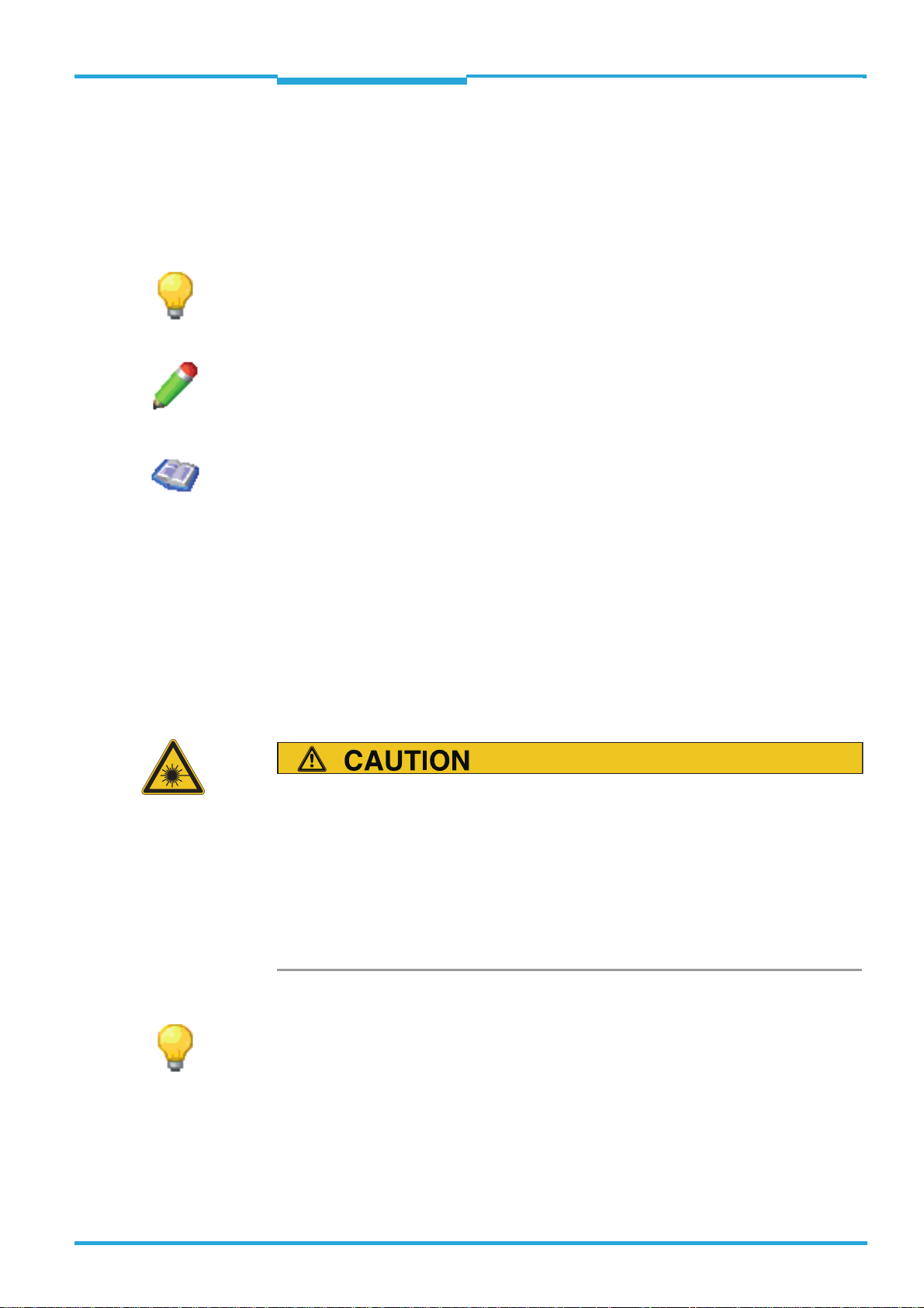
Module width/height in px
The module width and height of the codes is displayed in pixels in the M
IN PX column.
ODULE WIDTH/HEIGHT
The value can be used to evaluate the reading reliability (reserve) in relation to the image
resolution. The higher the value, the more reliable the reading. A value of at least 2/2, is
recommended, i.e. every code element is represented by at least 2/2 pixels.
By comparing the two values, you may be able to detect a distortion of the image or of the
code.
8013778/Y269/2013-11-27 © SICK AG · Germany · All rights reserved · Subject to change without notice 19
Page 20

Chapter 3 ONLINE HELP SOPAS
Online images
LECTOR®620
• The module width is the dimension of the smallest code element (bar of a bar code or dot
in a data matrix code) in pixels.
• The module height is the length of a bar of a bar code or the height of a dot in the data
matrix code.
3.1.3 Statistics
The display fields of the Statistics group are used to evaluate the reading results across all
triggers since the device was started or since the last reset.
The reading results during setup of the LECTOR
®
620 are not taken into consideration in the
statistics.
Reading gates The number of all triggers since the device was started or since the last reset are displayed
in the Reading gates display field.
The triggers during setup of the LECTOR
®
620 are not taken into consideration in the stati-
stics.
Good Reads The number of triggers for which the condition for Good Read was met is displayed in the
Good Reads display field.
The triggers during setup of the LECTOR
®
620 are not taken into consideration in the stati-
stics.
No Reads The number of triggers for which the condition for Good Read was NOT met is displayed in
the No Reads display field.
The triggers during setup of the LECTOR
®
620 are not taken into consideration in the stati-
stics.
Read rate The proportion of triggers for which the condition for Good Read compared to all triggers is
displayed as a % in the Read rate display field.
The triggers during setup of the LECTOR
®
620 are not taken into consideration in the stati-
stics.
Reset The Reset button is used to delete the values of the Reading gates, Good Reads, No Reads,
and Read rate display fields.
20 © SICK AG · Germany · All rights reserved · Subject to change without notice 8013778/Y269/2013-11-27
Page 21

ONLINE HELP SOPAS Chapter 4
LECTOR®620
Stored images
4 Stored images
Stored images can be displayed on the Stored images tab.
The images stored in the LECTOR
to the PC. The data (images, xml files, etc.) stored in the LECTOR
memory card can also be deleted.
By comparing and assessing the recorded images, you can, for example, analyze which
codes were not identified and whether faulty code structures have prevented a reading. For
this, the images displayed in reduced form in Image history are displayed by clicking in the
main view. The relevant code data is listed in Code infobox. To classify the recorded images
more effectively, you can use the right mouse button to display the date and time of recording.
For an evaluation of the current setting for the contrast, the identified codes are displayed
with different colors:
• Green (excellent): Contrast between 55 % and 100 %
• Yellow (good): Contrast between 20 % and 55 %
• Red (poor): Contrast less than 20 %
®
620 or on the MicroSD memory card can be transferred
®
620 or on the MicroSD
4.1 Saved images
Images that have been saved are displayed on the main display of the Saved images group.
The images saved in the LECTOR
to the PC, where they can be stored in a database, for example, and opened when required.
The data (images, .xml files, etc.) saved in the LECTOR
can also be deleted.
By comparing and evaluating the images that have been taken, it is possible to analyze,
for example, which codes were not identified and whether faulty code structures affected
the reading. Click on the smaller images on display in the Image history to display them in
the main view. The relevant code data is listed in the Code infobox. Right-clicking the mouse
displays the date and time the images were taken, allowing them to be organized better.
For an evaluation of the current setting for the contrast, the identified codes are displayed
with different colors:
• Green (excellent): Contrast between 55% and 100%
• Yellow (good): Contrast between 20% and 55%
• Red (poor): Contrast less than 20%
®
620 or on the microSD memory card can be transferred
®
620 or on the microSD memory card
Copying images The images saved in the LECTOR
®
620 or on the microSD memory card are transferred to
the PC via the Copying images button.
It is possible to select the storage location on the PC.
8013778/Y269/2013-11-27 © SICK AG · Germany · All rights reserved · Subject to change without notice 21
Page 22

Chapter 4 ONLINE HELP SOPAS
Stored images
LECTOR®620
Deleting images The data (images, .xml files, etc.) saved in the LECTOR®620 or on the microSD memory card
can also be removed by pressing the Deleting images button.
Loading images The images that have been transferred previously are displayed by pressing the Loading im-
ages button.
Toolbar Store
You can use the button to store the currently displayed image on the PC. For each stored
image, an xml file containing additional information is stored.
You can choose any image name and storage location.
Enlarge
You can use the button to enlarge the image in increments.
Reduce
You can use the button to reduce the image in increments.
You can also reduce the image using the mouse scroll wheel.
Standard size
You can use the button to display the image in its standard size.
4.1.1 Image history
In Image history, the recorded images are displayed one after the other. The images recorded most recently are added on the left.
By comparing and assessing the recorded images, you can analyze, for example,
• how often a code was recorded in total
• how often a code was recorded per reading gate
• whether the codes for moving objects were represented in focus and whether the shutter
time was set correctly
To find out the reason for unsuccessful readings, you may find it useful to analyze the
images without identified codes (N
O READ).
The images displayed in reduced form in Image history are displayed by clicking in the main
view. The file name and storage location of the images are displayed as a tooltip (mouseover).
You can use the and buttons to switch between several sequences.
22 © SICK AG · Germany · All rights reserved · Subject to change without notice 8013778/Y269/2013-11-27
Page 23

ONLINE HELP SOPAS Chapter 4
LECTOR®620
Stored images
The number of displayed images depends on the operating mode and the configuration:
• Depending on the configuration of the Image selection parameter, either the last 200 individual images are displayed (one individual image per trigger) or 60 images per second
are displayed in individual sequences.
• During reading to test the configuration (operating mode Setup), the last 30 images recorded are displayed.
4.1.2 Code infobox
The reading results are displayed in the Code infobox. To evaluate the readability and read
quality, the code contents are displayed along with other relevant data for all known codes.
Codes that have been detected several times in one image are listed one below the other.
The columns can be enlarged and their sequence changed using drag and drop.
C
ODE CONTENT
The contents of the codes are displayed in the CODE CONTENT column.
By assigning the code contents to the code, you can compare the read contents with the
actual contents of the code.
ODE ID
C
The code type of the code is displayed in the C
ODE ID column. By assigning the code type to
the code contents, you can activate/deactivate certain code types in the code configuration
in order to limit multiple contents to one code type, for example.
Code contrast PCS
The contrast of the codes in % is displayed in the C
ODE CONTRAST PCS column.
A high contrast simplifies identification of a code. By comparing different configurations,
you can find the setting for the highest possible contrast.
• From 55% to 100%: Contrast
EXCELLENT
• From 20% to 55%: Contrast GOOD
• Less than 20%: Contrast POOR
Module width/height in px
The module width and height of the codes is displayed in pixels in the M
IN PX column.
ODULE WIDTH/HEIGHT
8013778/Y269/2013-11-27 © SICK AG · Germany · All rights reserved · Subject to change without notice 23
Page 24

Chapter 4 ONLINE HELP SOPAS
Stored images
LECTOR®620
The value can be used to evaluate the reading reliability (reserve) in relation to the image
resolution. The higher the value, the more reliable the reading. A value of at least 2/2, is
recommended, i.e. every code element is represented by at least 2/2 pixels.
By comparing the two values, you may be able to detect a distortion of the image or of the
code.
• The module width is the dimension of the smallest code element (bar of a bar code or dot
in a data matrix code) in pixels.
• The module height is the length of a bar of a bar code or the height of a dot in the data
matrix code.
24 © SICK AG · Germany · All rights reserved · Subject to change without notice 8013778/Y269/2013-11-27
Page 25

ONLINE HELP SOPAS Chapter 5
LECTOR®620
Parameters
5 Parameters
Settings for protecting the configuration can be made on the Parameters tab.
The P
ARAMETER folder in the project tree combines all available parameters.
5.1 General
Password protection for the device configuration can be activated in the General group.
Password protection ensures that only authorized users can enter device parameters. This
prevents incorrect settings from being made.
5.1.1 Configuration is password protected
If this parameter is activated, access to the device configuration is password protected. To
be able to change parameters, you must log in to the device at the user level of authorized
customer or higher. You can use the SOPAS options, which can be found outside of the device configuration, without logging in. Password protection is activated the next time the device is restarted.
5.2 Auto setup via function button menu
The Auto setup via function button menu group contains the parameters for adjusting the
auto-setup wizards.
The A
UTO-SETUP function is divided into three individual modules:
• R
EADING DISTANCE
• IMAGE SETTINGS (brightness and contrast)
• C
ODE SETTINGS (currently only available for DATA MATRIX)
The A
UTO-SETUP function can be started in different ways:
• via wizard
• via the pushbuttons on LECTOR
• by pressing the A
UTO buttons
• via command (SOPAS command)
Commands for starting the A
•
SMN MASSTART: The Auto-Setup process is started.
•
SMN MASFINISH: The Auto-Setup process is stopped and the result is transmitted. To re-
turn to reading mode, you must end the Auto-Setup process with a stop command.
•
SMN MASCANCEL: The Auto-Setup process is stopped. This does, however, cause the result
to be discarded. To return to reading mode, you must end the Auto-Setup process with a
stop command.
®
620
UTO-SETUP function:
Even if you start the A
UTO-SETUP function via a command, the settings for the wizard
(standard or advanced) are taken into consideration. The settings can also be configured
using commands. A detailed list of commands can be obtained from SICK on request.
8013778/Y269/2013-11-27 © SICK AG · Germany · All rights reserved · Subject to change without notice 25
Page 26

Chapter 5 ONLINE HELP SOPAS
Parameters
LECTOR®620
5.2.1 Change reading distance
If the Change reading distance parameter is activated, the reading distance is modified
using the A
TOR
UTO-SETUP function. The function is called up using the buttons on the LEC-
®
620.
5.2.2 Change camera settings
If the Change camera settings parameter is activated, the brightness and contrast are modified using the A
®
TOR
620.
UTO-SETUP function. The function is called up using the buttons on the LEC-
5.2.3 Change code settings
If the Change code settings parameter is activated, the code settings for the D
symbology are modified using the A
buttons on the LECTOR
®
620.
UTO-SETUP function. The function is called up using the
ATAMATRIX
5.3 Function buttons
The Function buttons contains the parameters for defining the functions of the buttons on
®
620.
®
620.
®
620 are deactivated. As a result, you
®
620 having to be connected to the PC.
®
620 have a menu function and can
®
620 have a menu function and can
®
620 to carry out a rea-
the LECTOR
5.3.1 Function
You use the Function parameter to define the function and behavior of the buttons on the
LECTOR
• N
O FUNCTION: The function buttons on the LECTOR
can avoid malfunctions during operation caused by pressing the buttons by accident.
• T
RIGGER AND AIMING LASER: You can use the buttons on the LECTOR
ding without the LECTOR
- You use the left button to open the reading gate. The reading gate remains open until the
button is released again or until the condition for closing the reading gate has been met.
- You use the right button to turn the aiming laser on/off. The aiming laser is automatically
turned off after 5 minutes.
• M
ENU (SAVE PERMANENT): The buttons on the LECTOR
be used for parameterization. The changed parameter values are permanently stored in the
device. Existing values are overwritten.
• M
ENU (SAVE TEMPORARY): The buttons on the LECTOR
be used for parameterization. Existing values are initially overwritten. The changed parameter values are retained and stored in the device until the device is restarted. As the old parameter values are restored after the restart, this setting is useful for testing parameter
changes. The function can also be used to temporarily read another code and reset the settings by restarting the device.
26 © SICK AG · Germany · All rights reserved · Subject to change without notice 8013778/Y269/2013-11-27
Page 27

ONLINE HELP SOPAS Chapter 5
LECTOR®620
Parameters
If the menu function is activated, the following functions can be accessed using the buttons
on the LECTOR
• R
EAD DIAGN: A suitable code in the reading area is read with the current configuration. The
®
620:
reading rate of the last 10 readings is displayed in % via the bar chart on the housing of the
LECTOR
• T
®
620.
EACHIN MATCHCODE: A suitable code in the reading area is read and stored as a match-
code.
• A
UTO-SETUP (initially only available for DATA MATRIX): Depending on the configuration of the
parameters in the Auto setup via function button menu group, the reading distance, image
settings (brightness and contrast), and code settings are modified automatically. For this, a
suitable object with contrast changes or edges (e.g. code, text, or other structures) must be
placed in the reading area.
• A
UTOFOCUS: The focus position (reading distance) is modified automatically. For this, a sui-
table object with contrast changes or edges (e.g. code, text, or other structures) must be
placed in the reading area.
• U
SERDEFINED: (currently not implemented)
5.4 Reading configuration
5.4.1 Camera and lighting
All parameters that affect the quality of the images taken are combined on the Camera and
lighting tab.
Optimizing the camera and lighting settings improves the contrast, sharpness and illumination. This results in better code identification and therefore increases the reliability of the
reading.
A high image quality increases the time required to save the images taken. The save
times can be lowered by reducing the image quality.
5.4.1.1 Reading distance
The distance between the LECTOR
Reading distance group. The reading distance is used to adapt the focal range of the LEC-
®
TOR
620 to the mounting site.
The value can be entered manually in mm or set automatically via the Auto button.
To avoid disruptive reflections on the object surface, the LECTOR
ted on a suitable mounting bracket (see installation information).
®
620 and the object is set via the parameters for the
®
620 should be moun-
The reading distance affects the minimum code resolution and the size of the reading
area:
• If the reading distance is small, smaller codes can be read.
• A larger reading distance increases the reading area. The reduction in image brightness
caused by this is compensated for by the brightness control and, if necessary, by increasing
the shutter time.
8013778/Y269/2013-11-27 © SICK AG · Germany · All rights reserved · Subject to change without notice 27
Page 28
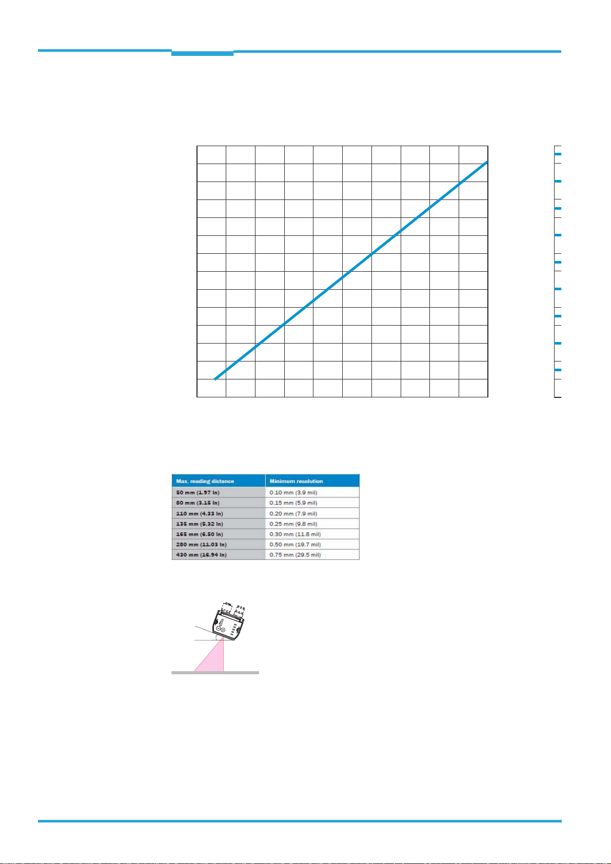
Chapter 5 ONLINE HELP SOPAS
0
100
(3.94)
150
(5.91)
200
(7.87)
250
(9.84)
300
(11.81)
350
(13.78)
325
(12.18)
50
(1.97)
75
(2.95)
125
(4.92)
175
(6.89)
225
(8.86)
275
(10.83)
25
(0.98)
100
(3.94)
150
(5.91)
200
(7.87)
250
(9.84)
300
(11.81)
350
(13.78)
325
(12.18)
50
(1.97)
75
(2.95)
125
(4.92)
175
(6.89)
225
(8.86)
275
(10.83)
25
(0.98)
64
(2.52)
96
(3.78)
128
(5.04)
160
(6.30)
192
(7.56)
224
(8.82)
00
32
(1.26)
48
(1.89)
80
(3.15)
112
(4.41)
144
(5.67)
176
(6.93)
208
(8.19)
16
(0.63)
050
(1.97)
100
(3.94)
150
(5.91)
200
(7.87)
250
(9.84)
300
(13.78)
350
(11.81)
400
(15.75)
450
(17.72)
500
(19.69)
Field of view/length in mm (inch)
Field of view/length in mm (inch)
Reading distance in mm (inch)
Field of view/width in mm (inch)
R =
typ. 20°
Parameters
LECTOR®620
Reference values for reading distance - reading field size - resolution
28 © SICK AG · Germany · All rights reserved · Subject to change without notice 8013778/Y269/2013-11-27
Maximum reading distance with minimum resolution
Skew angle, depending on the application
should typically be tilted by 20° out of the perpendicular in relation to the surface of the
code to avoid disruptive reflections.
In the case of codes created on metal, e.g., by dot peening, an angle of between 0° (bright
field light) and 45° (dark field light) may be advisable.
Page 29

ONLINE HELP SOPAS Chapter 5
LECTOR®620
Parameters
5.4.1.1.1 Reading distance
The Reading distance parameter is used to set the distance between the LECTOR
the object. The reading distance is used to modify the depth of field of the LECTOR
®
620 and
®
620 at
the installation location.
The value can be entered manually in mm or set automatically using the Auto button.
To avoid disruptive reflections on the object surface, the LECTOR
®
620 should be in-
stalled at a suitable fixing bracket (see installation information).
The reading distance influences the minimum code resolution and the size of the reading
area:
• If the reading distance is small, smaller codes can be read.
• A larger reading distance increases the reading area. The reduction in image brightness
caused by this is compensated for by the brightness control and, if necessary, by increasing
the shutter time.
5.4.1.1.2 Auto
Pressing the Auto button calls up the Auto Setup wizard for automatic configuration of the
reading distance.
For the reading distance to be adjusted automatically, a suitable object with contrast changes or edges (e.g. code, text, or other structures) must be placed in the reading area.
A prerequisite for automatic configuration of the reading distance is a certain basic
brightness at which the structures in the image are visible.
5.4.1.2 Exposure time
The time frame for taking an image is defined in μs via the parameters for the Exposure time
group.
• A short exposure time can accommodate high object speeds. As this causes the image
brightness to decrease, it may be necessary to adjust the signal amplification (Exposure
time). This does, however, increase the image noise.
• A long exposure time offers a high level of brightness and therefore minimal image noise.
This is the optimal setting for stationary or slow-moving objects.
5.4.1.2.1 Exposure time
The time frame for taking an image is defined in μs via the Exposure time parameter. The
exposure time can be set via the slide control.
• A short exposure time can accommodate high object speeds. As this causes the image
brightness to decrease, it may be necessary to adjust the signal amplification (Brightness).
This does, however, increase the image noise.
• A long exposure time offers a high level of brightness and therefore minimal image noise.
This is the optimal setting for stationary or slow-moving objects.
8013778/Y269/2013-11-27 © SICK AG · Germany · All rights reserved · Subject to change without notice 29
Page 30

Chapter 5 ONLINE HELP SOPAS
Parameters
LECTOR®620
5.4.1.2.2 Exposure time
The time frame for taking an image is defined in μs via the Exposure time parameter. The
exposure time can be entered in the input field.
• A short exposure time can accommodate high object speeds. As this causes the image
brightness to decrease, it may be necessary to adjust the signal amplification (Exposure
time). This does, however, increase the image noise.
• A long exposure time offers a high level of brightness and therefore minimal image noise.
This is the optimal setting for stationary or slow-moving objects.
5.4.1.3 Image settings
The image brightness and contrast settings are made via the parameters in the Image set-
tings group.
A good image that displays the code clearly is essential for a reliable reading. Optimizing the
image settings results in better code identification and therefore increases the reliability of
the reading.
5.4.1.3.1 Brightness
The amplification of the signal is set via the Brightness parameter. The signal amplification
can be set via the slide control.
The image brightness can be adjusted by amplifying the signal in order to achieve better visibility and decodability. When setting the signal amplification, it should be noted that an
overly high setting causes significant image noise and therefore makes it difficult to read
the code.
For this to be avoided, the value should be increased in stages until the code can be
read successfully.
5.4.1.3.2 Brightness
The amplification of the signal is set via the Brightness parameter. The signal amplification
value can be entered into the input field.
The image brightness can be adjusted by amplifying the signal in order to achieve better visibility and decodability. When setting the signal amplification, it should be noted that an
overly high setting causes significant image noise and therefore makes it difficult to read
the code.
For this to be avoided, the value should be increased in stages until the code can be
read successfully.
30 © SICK AG · Germany · All rights reserved · Subject to change without notice 8013778/Y269/2013-11-27
Page 31

ONLINE HELP SOPAS Chapter 5
LECTOR®620
Parameters
5.4.1.3.3 Contrast
The Contrast parameter is used to set the gamma correction in % and adapt it to the code
contrast. The gamma correction can be set via the slide control.
If the optical difference between black and white code elements is minimal, the parameter
should be set to a high value until the code elements can be clearly distinguished.
To monitor the contrast, the data in the Code infobox (C
ONTRAST) can be evaluated:
• 100%: Max. contrast
• 10%: Code can already be identified
5.4.1.3.4 Contrast
The Contrast parameter is used to set the gamma correction in % and adapt it to the code
contrast. The percentage value for the gamma correction can be entered into the input field.
If the optical difference between black and white code elements is minimal, the parameter
should be set to a high value until the code elements can be clearly distinguished.
To monitor the contrast, the data in the Code infobox (C
ONTRAST) can be evaluated:
• 100%: Max. contrast
• 10%: Code can already be identified
5.4.1.3.5 Auto
Pressing the Auto button calls up the Auto Setup wizard for automatic configuration of the
brightness and contrast.
For the settings to be adjusted automatically, a suitable object with contrast changes or
edges (e.g. code, text, or other structures) must be placed in the reading area.
5.4.1.4 Illumination
The parameters of the Illumination group are used to deactivate and configure the illumination elements.
Optimizing the settings leads to an optimum, high-contrast, and consistently illuminated
reading area. External influences caused by sun, darkness, room lighting, etc. can therefore
be minimized.
5.4.1.4.1 Internal
The Internal parameter is used to modify the internal illumination of the LECTOR
®
620 in line
with the application's in situ lighting situation.
• O
FF: If external illumination is used, the internal illumination can be deactivated.
• L
EFT/RED (type-dependent): This illumination type permits the maximum contrast for co-
des in the wavelength spectrum between blue and green.
8013778/Y269/2013-11-27 © SICK AG · Germany · All rights reserved · Subject to change without notice 31
Page 32

Chapter 5 ONLINE HELP SOPAS
Parameters
LECTOR®620
• RIGHT/BLUE (type-dependent): This lighting type offers the maximum contrast for codes in
the wavelength spectrum between green and red and can improve the reflective properties
of codes on metal surfaces.
• B
OTH/RED + BLUE (type-dependent): The combination of both illumination types offers the
maximum contrast for black codes. The reading area is illuminated uniformly with increased
light output. This setting is recommended for large reading distances and when the background color is unknown or subject to change.
• B
OTH/INFRARED (type-dependent): The advantage of the infrared lighting is that the light is
invisible to humans, meaning that no disruptive light sources are emitted from the device.
The code contrast achieved by the lighting is dependent on the code's material properties
and surface condition and must be tested.
Individual parameter values are not supported by all device types.
Optimal illumination of the reading field and an increased read rate are achieved by setting
the internal lighting.
5.4.1.4.2 Aiming laser
For various operating statuses, you can use the Aiming laser parameter to mark the optimum position for the codes in the center of the reading area directly on the object using the
integrated laser pointer.
As a result, you can easily position the codes manually and achieve optimum alignment.
• O
FF: Aiming laser is deactivated.
• L
IVE IMAGE, AUTO-SETUP: Aiming laser is only activated to set up the LECTOR
• T
RIGGER, LIVE IMAGE, AUTO-SETUP: Aiming laser remains activated as long as the reading gate
®
620.
is open.
To avoid malfunctions caused by the aiming laser, deactivate it (O
ding or if the position changes frequently, the T
RIGGER, LIVE IMAGE, AUTO-SETUP setting is re-
FF). For manual rea-
commended.
To activate/deactivate the aiming laser using keys on the LECTOR
parameter must have value T
RIGGER AND AIMING LASER.
®
620, the Function
32 © SICK AG · Germany · All rights reserved · Subject to change without notice 8013778/Y269/2013-11-27
Page 33

ONLINE HELP SOPAS Chapter 5
LECTOR®620
Parameters
5.4.1.4.3 Green feedback spot
The Green feedback spot parameter is used to select the condition causing a green LED
spot to be illuminated in the reading area. As a result, an optical notification can be set up
for a specific event.
The timeframe for illumination is defined using the Duration parameter.
• O
FF: The LED spot never illuminates.
• G
OOD READ: The green LED spot illuminates if reading was successful.
• N
O READ: The green LED spot illuminates if reading was unsuccessful.
• T
EACH-IN 1 OK: The green LED spot illuminates if the MATCHCODE TEACH-IN 1 was read in suc-
cessfully.
• T
EACH-IN 1 NOK: The green LED spot illuminates if the MATCHCODE TEACH-IN 1 was not read
in successfully.
• T
EACH-IN 2 OK: The green LED spot illuminates if the MATCHCODE TEACH-IN 2 was read in suc-
cessfully.
• T
EACH-IN 2 NOK: The green LED spot illuminates if the MATCHCODE TEACH-IN 2 was not read
in successfully.
• C
ONDITION MATCH1: The green LED spot illuminates if the read code corresponds to the
matchcode of C
• C
ONDITION MULTCODES1: The green LED spot illuminates if the number of read codes cor-
responds to the required number from C
• C
ONDITION TEACHIN1: The green LED spot illuminates if the read code corresponds to the
matchcode from C
• C
ONDITION TEACHIN2: The green LED spot illuminates if the read code corresponds to the
matchcode from C
ONDITION MATCH1.
ONDITION MULTCODES1.
ONDITION TEACHIN1.
ONDITION TEACHIN2.
5.4.1.4.4 Duration
The Duration parameter is used to define the timeframe for the optical notification (Green
feedback spot).
5.4.1.5 Image filters
Parameters for optimizing the camera image in the case of noise or special code markings
are combined in the Image filters group.
5.4.1.5.1 Noise suppression
Image smoothing is switched on and off via the Noise suppression parameter to pick out
the code clearly against the background.
8013778/Y269/2013-11-27 © SICK AG · Germany · All rights reserved · Subject to change without notice 33
Page 34
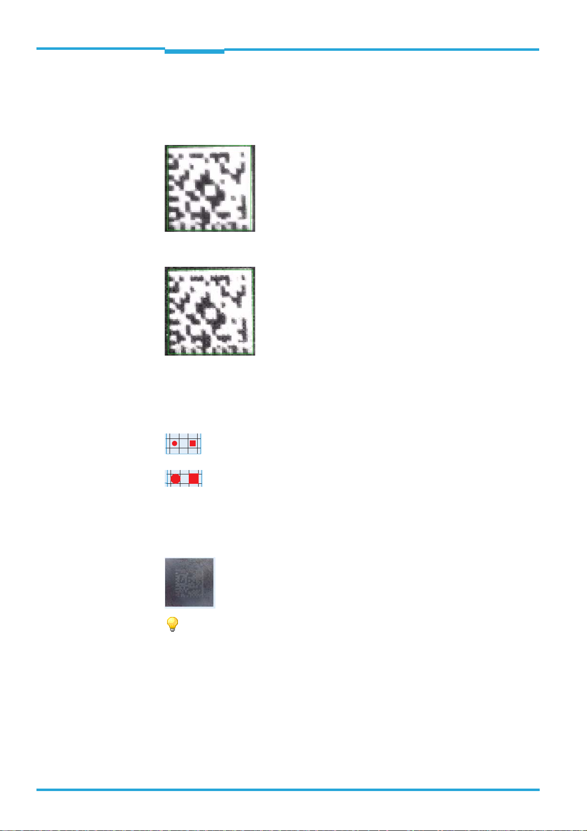
Chapter 5 ONLINE HELP SOPAS
Parameters
LECTOR®620
Smoothing improves the reading properties, particularly if the image appears to be affected
by noise or the code background is unstable due to a high level of amplification
(Brightness).
Without noise
With noise
5.4.1.5.2 Dot size
You can use the Dot size parameter to optically enlarge the code elements in order to adapt
the LECTOR
®
620 to hard-to-read codes (e.g. codes with gaps between the points of the L-
pattern).
: difficult to read
: ideal to read
In the case of codes that were created e.g. with inkjet printers, dot peeners, or lasers, the
code elements may not be connected in some cases. In this case, the readability of the codes can be improved by enlarging the code elements.
The value should be increased step by step until the code can be read successfully.
5.4.1.6 Increase performance
The parameters for the Increase performance group can be used to ensure the readability
of the codes at higher object speeds and/or to reduce the evaluation time.
34 © SICK AG · Germany · All rights reserved · Subject to change without notice 8013778/Y269/2013-11-27
Page 35

ONLINE HELP SOPAS Chapter 5
LECTOR®620
Parameters
5.4.1.6.1 Setting image frequency manually
If the Setting image frequency manually parameter is activated, the image frequency can
by specified by the user. If this parameter is deactivated, the reading device operates at maximum image frequency. The R
EQUEST button can be used to retrieve the current image fre-
quency of a connected device. There may be a deviation between the set image frequency
and the actual image frequency used by the reading device. The device adjusts the image
frequency to other settings such as the exposure time. A long exposure time significantly reduces the image frequency.
It makes sense to reduce the image frequency for slow applications in which the object containing the code moves past the reading device slowly. Reducing the image frequency increases the time for evaluating individual images. This results in increased reading
reliability for each individual image. Reduced image frequency is not suitable for fast applications, as you run the risk of not detecting the code on any image.
5.4.1.6.2 Image frequency input field
The required image frequency can be entered into the input field in Hz, number of images
/ s. A message appears if invalid values are entered.
5.4.1.6.3 Image rotation 180°
If the Image rotation 180° parameter is activated, the image is recorded rotated around
180°.
As the image is processed from the top down, codes in the top part of the image are identified earlier. By rotating the image around 180°, you can therefore reduce the evaluation
time for codes that are not positioned centrally. This is particularly true for readings at a
standstill.
5.4.1.6.4 Image region of interest
You can use the Image region of interest parameter to concentrate the reading area on the
required region.
A reduction in the reading area reduces the evaluation time and increases the frame rate.
This enables you to achieve higher object speeds.
To change the size of the reading area, you drag and drop the red marking or enter the
four percentage values.
5.4.2 Object trigger control
The Object trigger control tab contains the parameters for opening and closing the reading
gate.
8013778/Y269/2013-11-27 © SICK AG · Germany · All rights reserved · Subject to change without notice 35
Page 36

Chapter 5 ONLINE HELP SOPAS
Parameters
LECTOR®620
5.4.2.1 Starting/Stopping the object trigger
The Starting/Stopping the object trigger group contains the parameters for opening and
closing the reading gate.
To ensure that the image is taken at the correct time and the code is securely registered,
the electrical properties of the digital inputs must be adjusted to the sensors and triggers
that are connected.
Depending on the application, this ensures that the appropriate image region of interest is
recorded and that the settings are adjusted to the reading, whether this is in motion or stationary.
5.4.2.1.1 Trigger delay
The Trigger delay parameter is used to choose between configuration with units of length or
configuration with units of time.
• T
RACK CONTROLLED: The values of the Pause, Reading gate length, Start delay, and Stop de-
lay parameters are entered in mm. In the event of a track-controlled delay, the reading gate
is not opened until the object has continued to move a predefined distance after the trigger
signal.
• T
IME CONTROLLED: The values of the Pause, Reading gate length, Start delay, and Stop de-
lay parameters are entered in ms. In the event of a time-controlled delay, the reading gate
is not opened until a predefined time has elapsed after the trigger signal.
5.4.2.1.2 Start delay
You can use the Start delay parameter to influence the time for opening the reading gate.
The unit can be selected in the Trigger delay parameter.
A positive value causes the reading gate to be opened later, e.g. in order to only enter codes
that are at the rear of an object to therefore reduce the decoding time.
By modifying the trigger, you can adjust the image recording more accurately to the code
position.
•
A. START DELAY (additional time/distance in which the reading gate remains closed after
event A)
5.4.2.1.3 Start by
The Start by parameter is used to select the signal source for opening the reading gate.
• A S
TART BY (signal for opening reading gate)
36 © SICK AG · Germany · All rights reserved · Subject to change without notice 8013778/Y269/2013-11-27
Page 37

ONLINE HELP SOPAS Chapter 5
LECTOR®620
Parameters
If the reading gate is open, the LECTOR®620 records images with a frequency of 60 Hz and
evaluates these by codes. Ideally, at least one code will have been completely recorded and
identified on an image. If the reading gate is closed, no images are recorded.
Signal sources for opening the reading gate:
• S
ENSOR / RESULT 1: A signal at digital input 1 (e.g. via a light barrier) opens the reading
gate.
• S
ENSOR / RESULT 2: A signal at digital input 2 (e.g. via a light barrier) opens the reading
gate.
• E
XTERNAL INPUT 1: A signal at external digital input 1 (e.g. via a light barrier) opens the rea-
ding gate.
• E
XTERNAL INPUT 2: A signal at external digital input 2 (e.g. via a light barrier) opens the rea-
ding gate.
• SOPAS C
OMMAND: A command to open the reading gate is expected e.g. from an external
controller (PLC). (A detailed list of the command language is available from SICK on request.)
• A
UTO CYCLE: The reading gate is opened and closed automatically after a defined cycle
(using the Pulse and Pause parameters) (e.g. if the feed speed stays the same and the code
position is constant or for manual code reading)
• CAN: The signal for opening and closing the reading gate is expected via the CAN interface. In a network of devices that communicate with each other via the CAN network, the
signal for opening the reading gate can be distributed. For this, a suitable trigger signal is
received by a device (usually the master) and distributed to the other CAN network.
• U
SER DEFINED COMMAND: You can freely define a command for opening the reading gate,
which is e.g. generated by an external controller (PLC) and transmitted to the LECTOR
• F
REE RUNNING: The reading gate is permanently open. As a result, manual code reading is
®
620.
possible without an external trigger signal (e.g. from a light barrier). Signals for opening/closing the reading gate are ignored. As it is therefore not possible to define a specific point in
time for data output, a signal for N
ding speed depend on the degree of utilization of the LECTOR
O READ cannot be output. The time of output and the rea-
®
620.
5.4.2.1.4 Stop delay
You can use the Stop delay parameter to influence the time for closing the reading gate. The
unit can be selected in the Trigger delay parameter.
A positive value enables the reading gate to be closed later, e.g. to extend the evaluation
period for codes at the rear of an object.
•
B. STOP DELAY (additional time/distance for which the reading gate remains open after
event B)
8013778/Y269/2013-11-27 © SICK AG · Germany · All rights reserved · Subject to change without notice 37
Page 38

Chapter 5 ONLINE HELP SOPAS
Parameters
LECTOR®620
5.4.2.1.5 Stop by
The Stop by parameter is used to select the signal source/condition for closing the reading
gate.
• B S
TOP BY (signal for closing reading gate)
If the reading gate is open, the LECTOR
®
620 records images with a frequency of 60 Hz and
evaluates these by codes. Ideally, at least one code will have been completely recorded and
identified on an image. If the reading gate is closed, no images are recorded.
Signal sources for closing the reading gate:
• N
OT DEFINED: No function for closing the reading gate defined
• T
RIGGER SOURCE: The reading gate is closed by the same signal source that opened it. (For
example, opening of reading gate as soon as an object breaks a light barrier and closing of
reading gate as soon as the object is no longer in front of the light barrier.)
• S
ENSOR / RESULT 1: A signal at digital input 1 (e.g. via a light barrier) closes the reading
gate.
• S
ENSOR / RESULT 2: A signal at digital input 2 (e.g. via a light barrier) closes the reading
gate.
• E
XTERNAL INPUT 1: A signal at external digital input 1 (e.g. via a light barrier) closes the rea-
ding gate.
• E
XTERNAL INPUT 2: A signal at external digital input 2 (e.g. via a light barrier) closes the rea-
ding gate.
• SOPAS C
OMMAND: A standard command to close the reading gate is expected e.g. from an
external controller (PLC). (A detailed list of the command language is available from SICK
on request.)
• T
IMER/TRACKING: The reading gate remains open for a defined time/distance (Reading
gate length). If the speed of the objects remains the same, and increment pulse is not re-
quired (Increment source). If the speed changes, the signals of an incremental encoder, for
example, can be used to calculate the current speed. As a result, the reading gate can be
closed independently of the speed of the object as soon as the object has covered a certain
distance.
• G
OOD READ: The reading gate is closed as soon as the GOOD READ condition has been met
(e.g. the required number of codes was read). As a result, the reading gate is only open for
as long as required (direct notification of whether a code was identified).
• U
SER DEFINED COMMAND: You can freely define a command for closing the reading gate,
which is e.g. generated by an external controller (PLC) and transmitted to the LECTOR
• C
ONDITION MATCH 1: The reading gate is closed as soon as the condition is met.
• C
ONDITION MULTCODES1: The reading gate is closed as soon as the number of identified co-
®
620.
des matches the required number.
• C
ONDITION TEACHIN1: The reading gate is closed as soon as the Matchcode Teach-in 1 con-
dition is met.
• C
ONDITION TEACHIN2: The reading gate is closed as soon as the Match-code Teach-in 2 (Ad-
ditional) condition is met.
38 © SICK AG · Germany · All rights reserved · Subject to change without notice 8013778/Y269/2013-11-27
Page 39

ONLINE HELP SOPAS Chapter 5
LECTOR®620
Parameters
5.4.2.1.6 Reading gate length
If the T
IMER/TRACKING signal source is selected under the Stop by parameter, the Reading
gate length parameter is used to enter the duration for which the reading gate stays open.
The unit can be selected in the Trigger delay parameter.
5.4.2.1.7 Or
You can use the Or parameter to choose a second signal source/condition for closing the
reading gate.
For the reading gate to be closed, one of the signal sources/conditions must be met.
• N
OT DEFINED: No function for closing the reading gate defined
• T
RIGGER SOURCE: The reading gate is closed by the same signal source that opened it. (For
example, opening of reading gate as soon as an object breaks a light barrier and closing of
reading gate as soon as the object is no longer in front of the light barrier.)
• S
ENSOR / RESULT 1: A signal at digital input 1 (e.g. via a light barrier) closes the reading
gate.
• S
ENSOR / RESULT 2: A signal at digital input 2 (e.g. via a light barrier) closes the reading
gate.
• E
XTERNAL INPUT 1: A signal at external digital input 1 (e.g. via a light barrier) closes the rea-
ding gate.
• E
XTERNAL INPUT 2: A signal at external digital input 2 (e.g. via a light barrier) closes the rea-
ding gate.
• SOPAS C
OMMAND: A standard command to close the reading gate is expected e.g. from an
external controller (PLC). (A detailed list of the command language is available from SICK
on request.)
• T
IMER/TRACKING: The reading gate remains open for a defined time/distance (Reading
gate length).
• G
OOD READ: The reading gate is closed as soon as the GOOD READ condition has been met
(e.g. the required number of codes was read). As a result, the reading gate is only open for
as long as necessary (direct notification).
• U
SER DEFINED COMMAND: You can freely define a command for closing the reading gate,
which is e.g. generated by an external controller (PLC) and transmitted to the LECTOR
• C
ONDITION MATCH 1: The reading gate is closed as soon as the condition is met.
• C
ONDITION MULTCODES1: The reading gate is closed as soon as the number of identified co-
®
620.
des matches the required number.
• C
ONDITION TEACHIN1: The reading gate is closed as soon as the Matchcode Teach-in 1 con-
dition is met.
• C
ONDITION TEACHIN2: The reading gate is closed as soon as the Match-code Teach-in 2 (Ad-
ditional) condition is met.
8013778/Y269/2013-11-27 © SICK AG · Germany · All rights reserved · Subject to change without notice 39
Page 40

Chapter 5 ONLINE HELP SOPAS
Parameters
LECTOR®620
5.4.2.1.8 Or
You can use the Or parameter to choose a third signal source/condition for closing the reading gate.
For the reading gate to be closed, one of the signal sources/conditions must be met.
• N
OT DEFINED: No function for closing the reading gate defined
• T
RIGGER SOURCE: The reading gate is closed by the same signal source that opened it. (For
example, opening of reading gate as soon as an object breaks a light barrier and closing of
reading gate as soon as the object is no longer in front of the light barrier.)
• S
ENSOR / RESULT 1: A signal at digital input 1 (e.g. via a light barrier) closes the reading
gate.
• S
ENSOR / RESULT 2: A signal at digital input 2 (e.g. via a light barrier) closes the reading
gate.
• E
XTERNAL INPUT 1: A signal at external digital input 1 (e.g. via a light barrier) closes the rea-
ding gate.
• E
XTERNAL INPUT 2: A signal at external digital input 2 (e.g. via a light barrier) closes the rea-
ding gate.
• SOPAS C
OMMAND: A standard command to close the reading gate is expected e.g. from an
external controller (PLC). (A detailed list of the command language is available from SICK
on request.)
• T
IMER/TRACKING: The reading gate remains open for a defined time/distance (Reading
gate length).
• G
OOD READ: The reading gate is closed as soon as the GOOD READ condition has been met
(e.g. the required number of codes was read). As a result, the reading gate is only open for
as long as necessary (direct notification).
• U
SER DEFINED COMMAND: You can freely define a command for closing the reading gate,
which is e.g. generated by an external controller (PLC) and transmitted to the LECTOR
• C
ONDITION MATCH 1: The reading gate is closed as soon as the condition is met.
• C
ONDITION MULTCODES1: The reading gate is closed as soon as the number of identified co-
®
620.
des matches the required number.
• C
ONDITION TEACHIN1: The reading gate is closed as soon as the Matchcode Teach-in 1 con-
dition is met.
• C
ONDITION TEACHIN2: The reading gate is closed as soon as the Match-code Teach-in 2 (Ad-
ditional) condition is met.
5.4.2.1.9 Pulse
If the A
UTO CYCLE signal source is selected under the Start by parameter, the Pulse parame-
ter is used to enter the duration for which the reading gate stays open. The unit can be selected in the Trigger delay parameter.
5.4.2.1.10 Pause
If the A
UTO CYCLE signal source is selected under the Start by parameter, the Pause parame-
ter is used to enter the duration for which the reading gate is closed. The unit can be selected in the Trigger delay parameter.
40 © SICK AG · Germany · All rights reserved · Subject to change without notice 8013778/Y269/2013-11-27
Page 41

ONLINE HELP SOPAS Chapter 5
LECTOR®620
Parameters
5.4.2.1.11 Of
If the CAN signal source is selected under the Start by parameter, the Of parameter can be
used to enter the CAN address of a device from the CAN network. This device receives a suitable trigger signal and distributes it to the other devices in the CAN network.
5.4.2.1.12 Trigger echo on
If the C
OMMAND signal source is selected under the Start by parameter, the command is sent
from the LECTOR
®
620 as a response to the controller if the Trigger echo on parameter is
activated.
As a result, the controller can check transmitted SOPAS commands.
5.4.2.1.13 Reading gate on
Pressing the Reading gate on button manually opens the reading gate.
So that you can test the current settings, all outputs, output strings and image transmission
function in accordance with the configuration. The reading gate is closed in accordance with
the configuration.
This function is ideally suited to testing operating mode and simulating a machine trig-
ger with a mouse click.
5.4.2.1.14 Reading gate off
Pressing the Reading gate off button manually closes the reading gate.
This enables you to conclude the reading operation even if the configured condition for automatically closing the reading gate does not occur.
This function is ideally suited to testing operating mode and simulating a machine trig-
ger with a mouse click.
5.4.2.2 Trigger distribution
The communication from the trigger signal to network users is defined in the Trigger distri-
bution group.
In a network with several reading devices, it is often sufficient to use a photoelectric switch
or connect a reading device to the control. The trigger signal is then distributed to the network users.
The Trigger distribution function allows trigger signals and the number of photoelectric swit-
ches in use to be significantly reduced. This leads to a significant reduction in system complexity and cost.
8013778/Y269/2013-11-27 © SICK AG · Germany · All rights reserved · Subject to change without notice 41
Page 42

Chapter 5 ONLINE HELP SOPAS
Parameters
LECTOR®620
5.4.2.2.1 Distribution
The trigger signal communication is activated/deactivated and assigned to a communication network via the Distribution parameter.
EACTIVATED: The trigger is not distributed to other network users.
• D
• CAN: In a group of devices that communicate with each other via the CAN network, the
signal for opening the reading gate can be distributed. This involves an appropriate trigger
signal being received by one of the devices – usually the master – and distributed to the
remaining devices in the CAN network
5.5 Position
The coordinates and angles of the LECTOR®620 above the conveying system are defined on
the Position tab. In the application, this means that objects can be clearly assigned, a defined position can be output, and the objects can be aligned in relation to the reading point.
5.5.1 Coordinates
In the Coordinates group, the position of the device above the conveying system is defined
in relation to a neutral point. Establishing the device position makes it easier to map the position of an identified object at a later stage.
Looking in the conveying direction, the neutral point can generally be found on the bottom
right-hand edge of the conveying system.
5.5.1.1 X-coordinate
The distance between the reading device and the reference point in the X-direction, i.e.
along the length of the conveying direction, is entered under the X-coordinate parameter.
5.5.1.2 Y-coordinate
The distance between the reading device and the reference point in the Y-direction (at 90°
to the conveying direction), is entered under the Y-coordinate parameter.
5.5.1.3 Z-coordinate
The distance between the reading device and the reference point in the Z-direction, i.e. the
distance above the conveying line, is entered under the Z-coordinate parameter.
5.5.2 Angle
The three-dimensional position of the camera is defined in the Angle group.
5.5.2.1 Alpha
The device's Alpha angle in relation to the code and trigger position is defined under the
Alpha parameter.
Example: Setting the angle to 90° or 270°. The reading is taken perpendicular to the conveying direction.
42 © SICK AG · Germany · All rights reserved · Subject to change without notice 8013778/Y269/2013-11-27
Page 43

ONLINE HELP SOPAS Chapter 5
LECTOR®620
Parameters
5.5.2.2 Beta
The device's Beta angle in relation to the trigger position is defined under the Beta parameter.
5.5.2.3 Gamma
The device's Gamma angle in relation to the trigger position is defined under the Gamma
parameter.
5.6 Increment configuration
The Increment configuration tab contains the parameters for converting the signals for distances and speeds.
The signals are either generated by the configuration software (SOPAS) or CAN interface, or
via an incremental encoder on the digital input. Incremental encoders refer to sensors for
capturing positional changes (linear) or angle changes (rotating) that can capture the distance and direction or angle change and direction of rotation. They are also known as rotary encoders, incremental rotary encoders, and rotary pulse encoders.
5.6.1 Increment
The Increment group contains parameters for converting signals for distances and speeds.
The signals are either generated by the configuration software (SOPAS) or via the CAN interfaces or are generated via an incremental encoder on the digital input. Incremental encoders refer to sensors for capturing positional changes (linear) or angle changes (rotating)
that can capture the distance and direction or angle change and direction or rotation. They
are also known as relative encoders.
5.6.1.1 Increment source
The Increment source parameter is used to select the source of the incremental signals:
• F
IXED SPEED: You can use the Fixed speed parameter to enter a constant value for the feed
speed of the belt.
• S
ENSOR 1: The incremental signals are expected from a rotary encoder connected at digi-
tal input 1. You configure the digital input using the parameters for the Sensor / Result 1
group. The maximum input frequency at the input is 300 Hz.
• S
ENSOR 2: The incremental signals are expected from a rotary encoder connected at digi-
tal input 2. You configure the digital input using the parameters for the Sensor / Result 2
group. The maximum input frequency at the input is 300 Hz.
• CAN: The incremental signals are expected via the CAN interface.
• SOPAS C
OMMAND: Corresponding commands are expected as incremental signals. The
commands can be generated by an external control (PLC), for example, and transmitted to
the LECTOR
®
620 at defined intervals.
8013778/Y269/2013-11-27 © SICK AG · Germany · All rights reserved · Subject to change without notice 43
Page 44

Chapter 5 ONLINE HELP SOPAS
Parameters
LECTOR®620
5.6.1.2 Fixed speed
The Fixed speed parameter is used to enter a constant value for the feed speed of the conveyer belt in m/sec.
This speed is automatically converted to time/distance.
5.6.1.3 System increment resolution
You use the System increment resolution parameter to define the conversion factor for the
increment signal.
The value corresponds to the distance covered per increment in mm. For the concrete calculation of speeds and distances, the value must be adapted to the incremental encoder
used.
5.7 Code configuration
The Code configuration tab contains the decoding settings parameters for individual code
types. The code types are each assigned to a code structure.
As only activated code types are processed, the processing speed can be increased by
deactivating the code types that are not being used.
5.7.1 General
A wizard is available via the A
UTO button in the General group, which can be used to set the
code configuration automatically.
5.7.1.1 Automatic code configuration
Pressing the A
UTO button (Automatic code configuration) starts the auto-setup wizard for au-
tomatic code-type configuration.
To perform the code configuration automatically, a suitable code must be placed in the reading area.
5.7.2 1D Symbologies
The 1D Symbologies group contains all parameters for configuration of the 1D symbologies
(barcodes).
5.7.2.1 Minimum module width
The smallest structure for decoding a code is defined in mm via the Minimum module width
parameter.
To optimize the decoding process, the value should be adapted as closely as possible to the
smallest code element (module width) that actually exists within the code. An average module width must be specified in order to read codes with varying module widths reliably.
44 © SICK AG · Germany · All rights reserved · Subject to change without notice 8013778/Y269/2013-11-27
Page 45

ONLINE HELP SOPAS Chapter 5
LECTOR®620
Parameters
5.7.2.2 Codabar
If the Codabar parameter is activated, decoding is activated for the code type.
As only activated code types are processed, you can increase the processing speed by
specifically activating/deactivating the required code types.
• Code name: Codabar (two-value)
• Character set: 16 alphanumeric characters (10 digits, 6 special characters)
• Structure: 7 code elements (4 bars, 3 gaps); start character (A, B, C or D), code contents,
stop character (A, B, C or D)
• Intrinsic reliability: Low
• Space required: Variable
• Area of application: Packet and postal service
• Standard: EN 798 bar-coding
5.7.2.3 Code 39
If the Code 39 parameter is activated, decoding is activated for the code type.
As only activated code types are processed, you can increase the processing speed by
specifically activating/deactivating the required code types.
• Code name: Code 39 (two-value)
• Character set: 43 alphanumeric characters (10 digits, 26 letters, 7 special characters)
• Structure: 9 code elements (5 bars, 4 gaps), 3 of which wide and 6 narrow
• Intrinsic reliability: Medium
• Space required: High
• Standard: ISO/IEC 16388
• Area of application: Packet and postal service
5.7.2.4 UPC/GTIN/EAN
Activating the UPC/GTIN/EAN parameter starts the decoding process for the UPC A, UPC E,
GTIN 8 / EAN 8, and GTIN 13 / EAN 13 activated code types.
As only activated code types are processed, the processing speed can be increased by
specifically activating/deactivating the necessary code types.
8013778/Y269/2013-11-27 © SICK AG · Germany · All rights reserved · Subject to change without notice 45
Page 46

Chapter 5 ONLINE HELP SOPAS
Parameters
LECTOR®620
5.7.2.5 2/5 Interleaved
If the 2/5 Interleaved parameter is activated, decoding is activated for the code type.
As only activated code types are processed, you can increase the processing speed by
specifically activating/deactivating the required code types.
• Code name: 2/5 Interleaved or ITF (2-value)
• Character set: Numeric characters
• Structure: 5 code elements per character, 2 of which wide and 3 narrow (characters at
uneven positions are represented by bars. Characters at even positions are represented by
gaps.)
• Intrinsic reliability: Low
• Space required: Low (with up to 18 characters)
• Standard: ISO/IEC 16390
• Area of application: Packet and postal service
5.7.2.6 Code 93
If the Code 93 parameter is activated, decoding is activated for the code type.
As only activated code types are processed, you can increase the processing speed by
specifically activating/deactivating the required code types.
• Code name: Code 93 (4-value)
• Character set: 43 alphanumeric characters (10 digits, 26 upper-case letters, 7 special
characters: Blanks, -, ., $, /, + and %)
• Intrinsic reliability: Medium
• Space required: Low
• Standard: ISO/IEC 16388
• Area of application: Packet and postal service
5.7.2.7 Code 128 Family
If the Code 128 Family parameter is activated, decoding is activated jointly for code types
Code 128 and EAN 128. (Code type Pharmacode must be deactivated.)
As only activated code types are processed, you can increase the processing speed by
specifically activating/deactivating the required code types.
46 © SICK AG · Germany · All rights reserved · Subject to change without notice 8013778/Y269/2013-11-27
Page 47

ONLINE HELP SOPAS Chapter 5
LECTOR®620
Parameters
5.7.2.8 GS1 DataBar
If the GS1 DataBar parameter is activated, decoding is activated for the DataBar 14,
DataBar Expanded, and DataBar Limited active code types. This requires the Pharmacode
code type to be deactivated.
As only activated code types are processed, you can increase the processing speed by
deactivating the code types that are not being used.
5.7.2.9 Pharmacode
If the Pharmacode parameter is activated, decoding is activated for the code type.
All other code types are deactivated.
• Code name: Pharmacode (binary)
• Character set: Numeric characters (integers between 3 and 131070)
• Structure: Wide bars: 1, narrow bars: 0 (main code and additional code can have different
colors)
• Intrinsic reliability: High
• Space required: Low
• Standard: Barcode standard of the company Laetus
• Area of application: Packaging check in the pharmaceutical industry (agreement with reference code from a code list)
5.7.2.10 Stacked codes
The Stacked codes group contains all the parameters for configuring the stacked codes (se-
veral barcodes stacked in rows one above the other, with the same start and stop character).
5.7.2.10.1 PDF417
If the PDF417 parameter is activated, decoding is activated for the code type.
As only activated code types are processed, you can increase the processing speed by
specifically activating/deactivating the required code types.
• Code name: PDF417
• Character set: 2710 numeric, 1850 alphanumeric, 1400 ASCII or 1108 ISO characters
8013778/Y269/2013-11-27 © SICK AG · Germany · All rights reserved · Subject to change without notice 47
Page 48

Chapter 5 ONLINE HELP SOPAS
Parameters
LECTOR®620
• Symbol size: 3 - 90
• Intrinsic reliability: Very high (error correction)
• Space required: Very low
• Standard: ISO/IEC 15438
• Area of application: Packet and postal service
5.7.3 Increase 1D performance
It is possible to optimize the decoding process for 1D codes via the parameters for the
Increase 1D performance group. The parameters can be used to eliminate interference,
thereby increasing device performance.
Adapting the settings to suit the application reduces the decoding time and increases both
reading reliability and the readability of low-contrast, 1D codes.
5.7.3.1 Code contrast
To find the codes in the reading field, the image taken is searched thoroughly for structures
with sufficiently large contrast variations. A code pattern is only expected within these structures.
A minimum value for these contrast variations is defined in % via the Code contrast parameter. Areas where the contrast is below the defined value are not searched for code patterns.
• To read low-contrast codes reliably regardless, a low value (e.g., 10%) must be set. This
does, however, increase the decoding time, as it involves searching a larger image area.
• For high-contrast codes, the value can be increased accordingly. In this case, a correspondingly smaller image area is searched, which reduces the decoding time.
5.7.3.2 Code background
The decoding process can be limited to codes with a light or dank background color using
the Code background parameter, which reduces the decoding time.
• W
HITE: Only dark codes on a light background are read.
• B
LACK: Only light codes on a dark background (inverted codes) are read.
• B
OTH: Both dark codes on a light background and light codes on a dark background (in-
verted codes) are read.
5.7.4 2D code types
The 2D code types group contains all of the parameters for configuring the 2D code.
The fewer code types are activated in parallel, the faster the decoding process.
48 © SICK AG · Germany · All rights reserved · Subject to change without notice 8013778/Y269/2013-11-27
Page 49

ONLINE HELP SOPAS Chapter 5
LECTOR®620
Parameters
5.7.4.1 Minimum cell size
You use the Minimum cell size parameter to specify in mm the smallest structure of cells
for decoding a code.
To optimize decoding, the value should be tailored as accurately as possible to the smallest
code element (cell size) that actually occurs in the code. The cell size should be between 60
% and 105 % of the ideal cell size.
To be able to reliably read codes with different cell sizes, the value for the absolutely smallest cell size must be entered
5.7.4.2 Data matrix
If the Data matrix parameter is activated, decoding starts for the relevant code type.
As only activated code types are processed, the processing speed can be increased by specifically activating/deactivating the necessary code types.
• Code name: Data matrix
• Max. number of numeric characters: 3116
• Max. number of alphanumeric characters: 2335
• Max. number of ASCII characters: 1982
• Max. number of ISO characters: 1556
• Structure: Symbol with L pattern, rectangular symbols also possible
• Standard: ISO/IEC 16022
• Areas of application: Electronics, automotive, aviation, pharmaceuticals, and food pakkaging
8013778/Y269/2013-11-27 © SICK AG · Germany · All rights reserved · Subject to change without notice 49
Page 50

Chapter 5 ONLINE HELP SOPAS
Parameters
LECTOR®620
5.7.5 Increase 2D performance
It is possible to optimize the decoding process for 2D codes via the parameters for the
Increase 2D performance group. The parameters can be used to eliminate interference,
thereby increasing device performance.
Adapting the settings to suit the application reduces the decoding time and increases both
reading reliability and the readability of low-contrast, 2D codes.
5.7.5.1 Code contrast
To find the codes in the reading field, the image taken is searched thoroughly for structures
with sufficiently large contrast variations. A code pattern is only expected within these structures.
A minimum value for these contrast variations is defined in % via the Code contrast parameter. Areas where the contrast is below the defined value are not searched for code patterns.
• To read low-contrast codes reliably regardless, a low value (e.g., 10%) must be set. This
does, however, increase the decoding time, as it involves searching a larger image area.
• For high-contrast codes, the value can be increased accordingly. In this case, a correspondingly smaller image area is searched, which reduces the decoding time.
5.7.5.2 Code background
The decoding process can be limited to codes with a light or dank background color using
the Code background parameter, which reduces the decoding time.
• W
HITE: Only dark codes on a light background are read.
• B
LACK: Only light codes on a dark background (inverted codes) are read.
• B
OTH: Both dark codes on a light background and light codes on a dark background (in-
verted codes) are read.
5.7.5.3 Code alignment
The decoding process can be limited to mirrored or non-mirrored codes using the Code
alignment parameter, which reduces the decoding time.
• N
ORMAL: Only non-mirrored codes can be decoded correctly.
• M
IRRORED: Only mirrored codes that have been recorded from below through a glass pane,
for example, can be decoded correctly. This required the images taken prior to the decoding
process to be mirrored once again.
• B
OTH: Both mirrored and non-mirrored codes are read.
50 © SICK AG · Germany · All rights reserved · Subject to change without notice 8013778/Y269/2013-11-27
Page 51

ONLINE HELP SOPAS Chapter 5
LECTOR®620
Parameters
5.7.6 Codabar
If the Codabar parameter is activated, decoding is activated for the corresponding code type. The configuration tab for the relevant code type can be seen and opened in SOPAS ET.
As only activated code types are processed, you can increase the processing speed by
deactivating the code types that are not being used.
• Code name: Codabar (two-value)
• Character set: 16 alphanumeric characters (10 digits, 6 special characters)
• Structure: 7 code elements (4 bars, 3 gaps); start character (A, B, C or D), code content,
stop character (A, B, C or D)
• Intrinsic safety: Low
• Spatial requirements: Variable
• Area of application: Parcel and postal service
• Standard: EN 798 bar coding
5.7.6.1 General
Reading processes such as the number of necessary multireads, regulations for dealing
with the start and stop characters, or check digit tests are configured under the General
group.
5.7.6.1.1 Multiread
You use the Multiread parameter to define a minimum number of G
reading to be output as a G
OOD READ.
OOD READ required for a
By defining a minimum number of readings, you reduce the likelihood of misinterpretations
for codes with poor printing quality or a low contrast, and increase reading reliability.
5.7.6.1.2 Start/Stop identical
If the Start/Stop identical parameter is activated, only codes whose start character is the
same as the stop character are read.
A code of code type Codabar can have one of the four characters (A, B, C or D) as the start/
stop character. If only identical start and stop characters are permitted, the reading reliability is increased, and misinterpretations are avoided.
8013778/Y269/2013-11-27 © SICK AG · Germany · All rights reserved · Subject to change without notice 51
Page 52

Chapter 5 ONLINE HELP SOPAS
Parameters
LECTOR®620
5.7.6.1.3 Outputting start/stop
When the Outputting start/stop parameter is activated, the start and stop characters are
output along with the code content.
The characters are therefore available for evaluating the reading results.
5.7.6.1.4 Check digit test
This Check digit test parameter is used to define the calculation method for the plausibility
check on the code contents. A check digit is calculated from the code contents and compared with the check digit in the code. The selected method must match the method used during creation of the code. If the calculated check digit matches the check digit in the code,
the reading is regarded as a G
OOD READ).
Check digits prevent misinterpretations and increase reading reliability.
5.7.6.2 Length
Codes with a defined number of rows and columns can be excluded from the reading process via the parameters in the Length group. Limiting the number of codes to be read reduces the decoding time.
5.7.6.2.1 Code length
You can use the Code length parameter to restrict the permitted number of characters in a
code.
• F
REE: Codes of any code length are read.
• I
NTERVAL: The Interval parameter can be used to define the minimum and maximum code
length. Only codes with a code length between these two values are read.
• F
IXED: The Fixed length parameter is used to define several fixed code lengths. Only codes
with one of these defined code lengths are read.
52 © SICK AG · Germany · All rights reserved · Subject to change without notice 8013778/Y269/2013-11-27
Page 53

ONLINE HELP SOPAS Chapter 5
LECTOR®620
Parameters
5.7.6.2.2 Interval
The Interval parameter can be used to define the minimum and maximum code length. Only
codes with a code length between these two values are read.
By defining a minimum and maximum code length, you restrict the range of codes to be
read. This can lead to a reduction in the decoding time.
5.7.6.2.3 Fixed length
The Fixed length parameter is used to define several fixed code lengths. Only codes with one
of these defined code lengths are read.
By defining certain permitted code lengths, you restrict the range of codes to be read.
This can lead to a reduction in the decoding time.
5.7.7 Code 39
If the Code 39 parameter is activated, decoding is activated for the corresponding code type. The configuration tab for the corresponding code type can be seen and opened in
SOPAS ET.
As only activated code types are processed, you can increase the processing speed by
deactivating the code types that are not being used.
• Code name: Code 39 (two-value)
• Character set: 43 alphanumeric characters (10 digits, 26 letters, 7 special characters)
• Character set: 43 alphanumeric characters (10 digits, 26 letters, 7 special characters)
• Structure: 9 code elements (5 bars, 4 gaps) – 3 wide and 6 narrow
• Intrinsic safety: Average
• Spatial requirements: High
• Standard: ISO/IEC 16388
• Area of application: Parcel and postal service
5.7.7.1 General
Reading processes such as the number of necessary multireads, regulations for dealing
with the start and stop characters, or check digit tests are configured under the General
group.
5.7.7.1.1 Multiread
You use the Multiread parameter to define a minimum number of G
reading to be output as a G
OOD READ.
OOD READ required for a
By defining a minimum number of readings, you reduce the likelihood of misinterpretations
for codes with poor printing quality or a low contrast, and increase reading reliability.
8013778/Y269/2013-11-27 © SICK AG · Germany · All rights reserved · Subject to change without notice 53
Page 54

Chapter 5 ONLINE HELP SOPAS
Parameters
LECTOR®620
5.7.7.1.2 Transmit start/stop
If the Transmit start/stop parameter is activated, the start and stop characters are transmitted together with the code contents.
As a result, the characters are available for evaluation of the reading results.
5.7.7.1.3 Full ASCII
The Full ASCII parameter must be activated if the code contains both digits and other characters.
5.7.7.1.4 Check digit test
This Check digit test parameter is used to define the calculation method for the plausibility
check on the code contents. A check digit is calculated from the code contents and compared with the check digit in the code. The selected method must match the method used during creation of the code. If the calculated check digit matches the check digit in the code,
the reading is regarded as a G
OOD READ).
Check digits prevent misinterpretations and increase reading reliability.
5.7.7.1.5 C32 conversion
If the C32 conversion parameter is activated, decoding is activated for the code type.
As only activated code types are processed, you can increase the processing speed by
specifically activating/deactivating the required code types.
• Code name: C32 conversion (two-value)
• Character set: 32 alphanumeric characters (upper case letters A - Z, digits 0 - 9, no special
characters)
• Structure: Leading light zone, start character, message characters, check digit, stop character, closing light zone (13 - 16 modules per character)
• Intrinsic reliability: High
• Space required: Variable symbol length
• Standard: ISO/IEC 16388, ANSI/AIM BC5 1995
• Area of application: Article number for pharmaceutical products (Italian pharmaceutical
code), drug packaging for human medicine
54 © SICK AG · Germany · All rights reserved · Subject to change without notice 8013778/Y269/2013-11-27
Page 55

ONLINE HELP SOPAS Chapter 5
LECTOR®620
Parameters
5.7.7.1.6 Hex – ASCII output
If the Hex – ASCII output parameter is activated, every code character is output as a hexadecimal value. If the parameter has deactivated the hexadecimal output, the code contents
are output directly as ASCII characters. If the code contains control characters during the
ASCII output, these are replaced by the @ character to avoid conflicts with the protocol framework.
Converting the code contents into hexadecimal values enables all characters – including
control characters – to be output.
5.7.7.2 Length
Codes with a defined number of characters can be excluded from the reading process via
the parameters in the Length group.
Limiting the number of codes to be read reduces the decoding time.
5.7.7.2.1 Code length
You can use the Code length parameter to restrict the permitted number of characters in a
code.
• F
REE: Codes of any code length are read.
• I
NTERVAL: The Interval parameter can be used to define the minimum and maximum code
length. Only codes with a code length between these two values are read.
• F
IXED: The Fixed length parameter is used to define several fixed code lengths. Only codes
with one of these defined code lengths are read.
5.7.7.2.2 Interval
The Interval parameter can be used to define the minimum and maximum code length. Only
codes with a code length between these two values are read.
By defining a minimum and maximum code length, you restrict the range of codes to be
read. This can lead to a reduction in the decoding time.
5.7.7.2.3 Fixed length
The Fixed length parameter is used to define several fixed code lengths. Only codes with one
of these defined code lengths are read.
By defining certain permitted code lengths, you restrict the range of codes to be read.
This can lead to a reduction in the decoding time.
5.7.8 UPC/GTIN/EAN
If the UPC/GTIN/EAN parameter is activated, decoding is activated for the UPC A, UPC E,
GTIN 8 / EAN 8, and GTIN 13 / EAN 13 active code types. The configuration tab for the cor-
responding code types can be seen and opened in SOPAS ET.
As only activated code types are processed, you can increase the processing speed by
deactivating the code types that are not being used.
8013778/Y269/2013-11-27 © SICK AG · Germany · All rights reserved · Subject to change without notice 55
Page 56

Chapter 5 ONLINE HELP SOPAS
Parameters
LECTOR®620
5.7.8.1 General
Reading processes such as the number of necessary multireads, regulations for dealing
with the start and stop characters, or check digit tests are configured under the General
group.
5.7.8.1.1 Multiread
You use the Multiread parameter to define a minimum number of G
reading to be output as a G
OOD READ.
OOD READ required for a
By defining a minimum number of readings, you reduce the likelihood of misinterpretations
for codes with poor printing quality or a low contrast, and increase reading reliability.
5.7.8.1.2 Add-on
The Add-on parameter is used to configure how the extended code structure is used (additional information usually on magazines).
• N
ONE: No extended code structure for the code
• A
CTIVE: Extended code structure for the code
• R
EQUIRED: Only codes with an extended code structure are read.
Add-on length The Add-on length parameter is used to define the length of the extended code structure.
• 2
DIGITS: A 1
• 5
DIGITS: A 1 B 2 C
• 2
OR 5 DIGITS: A 1 or A 1 B 2 C
5.7.8.2 UPC
The UPC A, UPC E and UPC E extended code types can be activated or deactivated under
the UPC group.
5.7.8.2.1 UPC A
If the UPC A parameter is activated, decoding is activated for the code type.
As only activated code types are processed, you can increase the processing speed by
specifically activating/deactivating the required code types.
• Code name: UPC A (Universal Product Code) (4-value)
• Character set: 12 numeric characters (check digit: last character)
• Structure: 2 characters for country prefix, 9 characters for manufacturer and article, 1
character as check digit
56 © SICK AG · Germany · All rights reserved · Subject to change without notice 8013778/Y269/2013-11-27
Page 57

ONLINE HELP SOPAS Chapter 5
LECTOR®620
Parameters
• Intrinsic reliability: High
• Space required: Low
• Standard: DIN/EN 797
• Area of application: Food and consumer goods in the USA and Canada
5.7.8.2.2 UPC E
If the UPC E parameter is activated, decoding is activated for the code type.
As only activated code types are processed, you can increase the processing speed by
specifically activating/deactivating the required code types.
• Code name: UPC E (Universal Product Code) (4-value)
• Character set: 8 numeric characters
• Structure: System ID (always 0), 2 characters for country prefix, 4 characters for manufacturer and article, 1 character as check digit
• Intrinsic reliability: High
• Space required: Low
• Standard: DIN/EN 797
• Area of application: Food and consumer goods in the USA and Canada
5.7.8.2.3 UPC E extended
If the UPC E extended parameter is activated, 8-character codes of code type UPC E are au-
tomatically converted to 12-character codes. (Code type Pharmacode must be deactivated.)
5.7.8.3 EAN
The GTIN 8 / EAN 8 and GTIN 13 / EAN 13 code types can be activated or deactivated under
the EAN group.
5.7.8.3.1 GTIN 8 / EAN 8
If the GTIN 8 / EAN 8 parameter is activated, decoding starts for the relevant code type.
As only activated code types are processed, you can increase the processing speed by
deactivating the code types that are not being used.
• Code name: GTIN 8 / EAN 8 (European Article Numbering) (4-value)
• Character set: 8 numerical characters (check digits: last two characters)
8013778/Y269/2013-11-27 © SICK AG · Germany · All rights reserved · Subject to change without notice 57
Page 58

Chapter 5 ONLINE HELP SOPAS
Parameters
LECTOR®620
• Structure: 2 characters for country prefix (in accordance with GS1 standards), 4 characters for the manufacturer and part (in accordance with GS1 standards), 2 characters as
check digits
• Intrinsic safety: High
• Spatial requirements: Low
• Standard: DIN/EN 797
• Areas of application: Foodstuffs and consumer goods in Europe
5.7.8.3.2 GTIN 13 / EAN 13
If the GTIN 13 / EAN 13 parameter is activated, decoding starts for the relevant code type.
As only activated code types are processed, you can increase the processing speed by
deactivating the code types that are not being used.
• Code name: GTIN 13 / EAN 13 (European Article Numbering) (4-value)
• Character set: 13 numerical characters (check digits: last two characters)
• Structure: 2 characters for country prefix (in accordance with GS1 standards), 8 characters for the manufacturer and part (in accordance with GS1 standards), 2 characters as
check digits
• Intrinsic safety: High
• Spatial requirements: Low
• Standard: DIN/EN 797
• Areas of application: Foodstuffs and consumer goods in Europe
5.7.9 2/5 interleaved
If the 2/5 interleaved parameter is activated, decoding is activated for the corresponding
code type. The configuration tab for the corresponding code type can be seen and opened
in SOPAS ET.
As only activated code types are processed, you can increase the processing speed by
deactivating the code types that are not being used.
• Code name: 2/5 interleaved or ITF (2-value)
• Character set: Numeric characters
• Structure: 5 code elements per character, 2 of which wide and 3 narrow (characters at
uneven positions are represented by bars. Characters at even positions are represented by
gaps.)
• Intrinsic safety: Low
• Spatial requirements: Low (up to 18 characters)
58 © SICK AG · Germany · All rights reserved · Subject to change without notice 8013778/Y269/2013-11-27
Page 59

ONLINE HELP SOPAS Chapter 5
LECTOR®620
Parameters
• Standard: ISO/IEC 16390
• Area of application: Parcel and postal service
5.7.9.1 General
Reading processes such as the number of necessary multireads, regulations for dealing
with the start and stop characters, or check digit tests are configured under the General
group.
5.7.9.1.1 Multiread
You use the Multiread parameter to define a minimum number of G
reading to be output as a G
OOD READ.
OOD READ required for a
By defining a minimum number of readings, you reduce the likelihood of misinterpretations
for codes with poor printing quality or a low contrast, and increase reading reliability.
5.7.9.1.2 Check digit test
This Check digit test parameter is used to define the calculation method for the plausibility
check on the code contents. A check digit is calculated from the code contents and compared with the check digit in the code. The selected method must match the method used during creation of the code. If the calculated check digit matches the check digit in the code,
the reading is regarded as a G
OOD READ).
Check digits prevent misinterpretations and increase reading reliability. The use of a
check digit is recommended for this code type.
5.7.9.1.3 Check-Digit-Test #2
Check-Digit-Test #2
5.7.9.1.4 Check-Digit-Test #3
Check-Digit-Test #3
5.7.9.1.5 Check-Digit-Test #4
Check-Digit-Test #4
5.7.9.1.6 Check-Digit-Test #5
Check-Digit-Test #5
5.7.9.2 Length
Codes with a defined number of characters can be excluded from the reading process via
the parameters in the Length group.
Limiting the number of codes to be read reduces the decoding time.
8013778/Y269/2013-11-27 © SICK AG · Germany · All rights reserved · Subject to change without notice 59
Page 60

Chapter 5 ONLINE HELP SOPAS
Parameters
LECTOR®620
5.7.9.2.1 Code length
You can use the Code length parameter to restrict the permitted number of characters in a
code.
• F
REE: Codes of any code length are read.
• I
NTERVAL: The Interval parameter can be used to define the minimum and maximum code
length. Only codes with a code length between these two values are read.
• F
IXED: The Fixed length parameter is used to define several fixed code lengths. Only codes
with one of these defined code lengths are read.
5.7.9.2.2 Interval
The Interval parameter can be used to define the minimum and maximum code length. Only
codes with a code length between these two values are read.
By defining a minimum and maximum code length, you restrict the range of codes to be
read. This can lead to a reduction in the decoding time.
5.7.9.2.3 Fixed length
The Fixed length parameter is used to define several fixed code lengths. Only codes with one
of these defined code lengths are read.
By defining certain permitted code lengths, you restrict the range of codes to be read.
This can lead to a reduction in the decoding time.
5.7.10 Code 93
If the Code 93 parameter is activated, decoding is activated for the corresponding code type. The configuration tab for the corresponding code type can be seen and opened in
SOPAS ET.
As only activated code types are processed, you can increase the processing speed by
deactivating the code types that are not being used.
• Code name: Code 93 (4-value)
• Character set: 43 alphanumeric characters (10 digits, 26 upper-case letters, 7 special
characters: Space, -, ., $, /, +, and %)
• Intrinsic safety: Average
• Spatial requirements: Low
• Standard: ISO/IEC 16388
• Area of application: Parcel and postal service
60 © SICK AG · Germany · All rights reserved · Subject to change without notice 8013778/Y269/2013-11-27
Page 61

ONLINE HELP SOPAS Chapter 5
LECTOR®620
Parameters
5.7.10.1 General
Reading processes such as the number of necessary multireads, regulations for dealing
with the start and stop characters, or check digit tests are configured under the General
group.
5.7.10.1.1 Multiread
You use the Multiread parameter to define a minimum number of G
reading to be output as a G
OOD READ.
OOD READ required for a
By defining a minimum number of readings, you reduce the likelihood of misinterpretations
for codes with poor printing quality or a low contrast, and increase reading reliability.
5.7.10.2 Length
Codes with a defined number of characters can be excluded from the reading process via
the parameters in the Length group.
Limiting the number of codes to be read reduces the decoding time.
5.7.10.2.1 Code length
You can use the Code length parameter to restrict the permitted number of characters in a
code.
• F
REE: Codes of any code length are read.
• I
NTERVAL: The Interval parameter can be used to define the minimum and maximum code
length. Only codes with a code length between these two values are read.
• F
IXED: The Fixed length parameter is used to define several fixed code lengths. Only codes
with one of these defined code lengths are read.
5.7.10.2.2 Interval
The Interval parameter can be used to define the minimum and maximum code length. Only
codes with a code length between these two values are read.
By defining a minimum and maximum code length, you restrict the range of codes to be
read. This can lead to a reduction in the decoding time.
5.7.10.2.3 Fixed length
The Fixed length parameter is used to define several fixed code lengths. Only codes with one
of these defined code lengths are read.
By defining certain permitted code lengths, you restrict the range of codes to be read.
This can lead to a reduction in the decoding time.
8013778/Y269/2013-11-27 © SICK AG · Germany · All rights reserved · Subject to change without notice 61
Page 62

Chapter 5 ONLINE HELP SOPAS
Parameters
LECTOR®620
5.7.11 Code 128 family
If the Code 128 family parameter is activated, decoding is activated for the Code 128 and
EAN 128 active code types. This requires the Pharmacode code type to be deactivated. The
configuration tab for the corresponding code types can be seen and opened in SOPAS ET.
As only activated code types are processed, you can increase the processing speed by
deactivating the code types that are not being used.
5.7.11.1 General
Reading processes such as the number of necessary multireads, regulations for dealing
with the start and stop characters, or check digit tests are configured under the General
group.
5.7.11.1.1 Code 128
If the Code 128 parameter is activated, decoding starts for the relevant code type. This requires the Pharmacode code type to be deactivated.
As only activated code types are processed, the processing speed can be increased by
specifically activating/deactivating the necessary code types.
• Code name: Code 128 (4-value)
• Character set: alphanumeric (ASCII) with three switchable character sets and one check
digit
Character set A: Digits, upper-case letters, special characters, and ASCII control characters
Character set B: Digits, upper-case and lower-case letters, special characters and escape
characters
Character set C: 100 pairs of digits (00 to 99) and FNC1 special characters
• Structure: Start symbol, useful information, check digit, stop symbol (11 modules per
symbol, each with 3 bars and 3 gaps)
• Intrinsic safety: Very high (self-checking: Even number of bars, uneven number of gaps)
• Spatial requirements: Largest possible number of characters per centimeter
• Standard: ISO/IEC 15420
• Area of application: All areas, as UCC 128/EAN 128 in retail
5.7.11.1.2 EAN 128
If the EAN 128 parameter is activated, decoding is activated for the code type. (Code type
Pharmacode must be deactivated.)
As only activated code types are processed, you can increase the processing speed by
specifically activating/deactivating the required code types.
62 © SICK AG · Germany · All rights reserved · Subject to change without notice 8013778/Y269/2013-11-27
Page 63

ONLINE HELP SOPAS Chapter 5
LECTOR®620
Parameters
• Code name: EAN 128 (4-value)
• Character set: Alphanumeric (ASCII) with three switchable character sets
Character set A: Digits, upper case letters, and special characters
Character set B: Digits, upper and lower case letters
Character set C: Digits with double density
• Structure: FNC1, characters, check digit
• Intrinsic reliability: High
• Space required: Low
• Standard: ISO/IEC 15417
• Area of application: Marking of commodities
5.7.11.1.3 Multiread
You use the Multiread parameter to define a minimum number of G
reading to be output as a G
OOD READ.
OOD READ required for a
By defining a minimum number of readings, you reduce the likelihood of misinterpretations
for codes with poor printing quality or a low contrast, and increase reading reliability.
5.7.11.2 Length
Codes with a defined number of characters can be excluded from the reading process via
the parameters in the Length group.
Limiting the number of codes to be read reduces the decoding time.
5.7.11.2.1 Code length
You can use the Code length parameter to restrict the permitted number of characters in a
code.
• F
REE: Codes of any code length are read.
• I
NTERVAL: The Interval parameter can be used to define the minimum and maximum code
length. Only codes with a code length between these two values are read.
• F
IXED: The Fixed length parameter is used to define several fixed code lengths. Only codes
with one of these defined code lengths are read.
5.7.11.2.2 Interval
The Interval parameter can be used to define the minimum and maximum code length. Only
codes with a code length between these two values are read.
By defining a minimum and maximum code length, you restrict the range of codes to be
read. This can lead to a reduction in the decoding time.
8013778/Y269/2013-11-27 © SICK AG · Germany · All rights reserved · Subject to change without notice 63
Page 64

Chapter 5 ONLINE HELP SOPAS
Parameters
LECTOR®620
5.7.11.2.3 Fixed length
The Fixed length parameter is used to define several fixed code lengths. Only codes with one
of these defined code lengths are read.
By defining certain permitted code lengths, you restrict the range of codes to be read.
This can lead to a reduction in the decoding time.
5.7.11.3 GS1/EAN 128
The control characters in the EAN 128 code format can be replaced with alternative, userspecific characters under the GS1/EAN 128 group. Control characters in the EAN 128 code
format are used at the start of the code to identify the code format and within the code to
classify the data groups. The user-specific characters are entered via the keyboard or clipboard as hexadecimal values.
5.7.11.3.1 FC1-Value within code
With the parameter FC1-Value within code an alternative character for the FC1-character
(control character at the beginning of the code) can be defined for the EAN 128 code.
Up to three characters can be defined. Enter data as a decimal character.
5.7.11.3.2 FC1-Value on first position
With the parameter FC1-Value on first position an alternative character for the FC1-character (control character at the beginning of the code) can be defined for the EAN 128 code.
Up to three characters can be defined. Enter data as a decimal character.
5.7.12 GS1 DataBar
If the GS1 DataBar parameter is activated, decoding is activated for the DataBar 14,
DataBar Expanded and DataBar Limited active code types. This requires the Pharmacode
code type to be deactivated. The configuration tab for the corresponding code types can be
seen and opened in SOPAS ET.
As only activated code types are processed, you can increase the processing speed by
deactivating the code types that are not being used.
5.7.12.1 General
Reading processes such as the number of necessary multireads, regulations for dealing
with the start and stop characters, or check digit tests are configured under the General
group.
64 © SICK AG · Germany · All rights reserved · Subject to change without notice 8013778/Y269/2013-11-27
Page 65

ONLINE HELP SOPAS Chapter 5
LECTOR®620
Parameters
5.7.12.1.1 DataBar 14
If the DataBar 14 parameter is activated, decoding starts for the relevant code type.
As only activated code types are processed, you can increase the processing speed by
deactivating the code types that are not being used.
• Code name: DataBar 14
• Character set: 14 fixed digits
• Structure: 94 modules divided into 46 elements; code words consist of 15 or 16 modules
and are displayed with 4 gaps and 4 lines; the pattern has 14 modules; the lines and gaps
are shown with 8 different module widths, i.e. the elements can be between 1X and 8X wide
• Intrinsic safety: High
• Standard: ISO/IEC 2427
• Area of application: Trade
5.7.12.1.2 DataBar Expanded
If the DataBar Expanded parameter is activated, decoding starts for the relevant code type.
As only activated code types are processed, you can increase the processing speed by
deactivating the code types that are not being used.
• Code name: GS1 DataBar Expanded (GDBE)
• Character set: Max. 74 digits, max. 41 characters
• Structure: 2 corner characters: 2 modules each, both containing 1 bar and 1 gap; 4-22
data characters: 17 modules each, both containing 4 bars and 4 gaps; 2-11 patterns and
1 check digit
• Intrinsic safety: High
• Spatial requirements: Variable
• Standard: ISO/IEC 646
• Areas of application: Variable-measure foods, coupons
8013778/Y269/2013-11-27 © SICK AG · Germany · All rights reserved · Subject to change without notice 65
Page 66

Chapter 5 ONLINE HELP SOPAS
Parameters
LECTOR®620
5.7.12.1.3 DataBar Limited
If the DataBar Limited parameter is activated, decoding starts for the relevant code type.
As only activated code types are processed, you can increase the processing speed by
deactivating the code types that are not being used.
• Code name: GS1 DataBar Limited (GDBL)
• Character set: 14 fixed digits
• Structure: No quiet zone, the separator consists of a gap (1X) and a line (1X)
• Intrinsic safety: High
• Spatial requirements: Low
• Standard: ISO/IEC 24727
• Areas of application: Trade and industry (pharmaceuticals industry and electronics sector)
5.7.13 Pharmacode
If the Pharmacode parameter is activated, decoding is activated for the corresponding code
type. The configuration tab for the corresponding code type can be seen and opened in
SOPAS ET.
All other code types are deactivated.
• Code name: Pharmacode (binary)
• Character set: Numeric characters (integers between 3 and 131,070)
Structure: Wide bars: 1, narrow bars: 0 (main code and additional code can have different
colors)
• Intrinsic safety: High
• Spatial requirements: Low
• Standard: Laetus bar code standard
• Area of application: Packaging checks in the pharmaceutical industry (agreement with reference code from a code list)
5.7.13.1 General
General (PHARMA)
66 © SICK AG · Germany · All rights reserved · Subject to change without notice 8013778/Y269/2013-11-27
Page 67

ONLINE HELP SOPAS Chapter 5
LECTOR®620
Parameters
5.7.13.1.1 Multiread
User-defined module
width
You use the Multiread parameter to define a minimum number of G
reading to be output as a G
OOD READ.
OOD READ required for a
By defining a minimum number of readings, you reduce the likelihood of misinterpretations
for codes with poor printing quality or a low contrast, and increase reading reliability.
5.7.13.1.2 Module width
You can use the Module width parameter to choose between the automatic and user-defined module width.
You use the User-defined module width parameter to specify in mm the smallest structure
for decoding a code.
Missing start and stop characters for codes of code type Pharmacode mean that incorrect
readings could occur for structures with a similar code. To increase reading reliability, the
value should be tailored as accurately as possible to the smallest code element (module
width) that actually occurs in the code.
5.7.13.1.3 Reverse
If the Reverse parameter is activated, the code is read in reverse direction.
As the codes of code type Pharmacode do not have a start or stop character and do not have
a check digit at the end, the code contents differ depending on the reading direction. The
reading direction must therefore be defined in the configuration.
5.7.13.2 Not calibratable
Not calibratable (PHARMA)
5.7.13.2.1 Fixed length
The Fixed length parameter can be used to define a required code length. Only codes with
this length are read.
5.7.14 Data matrix
If the Data matrix parameter is activated, decoding is activated for the corresponding code
type. The configuration tab for the corresponding code type can be seen and opened in
SOPAS ET.
As only activated code types are processed, you can increase the processing speed by deactivating the code types that are not being used.
• Code name: Data matrix
• Max. number of numeric characters: 3116
8013778/Y269/2013-11-27 © SICK AG · Germany · All rights reserved · Subject to change without notice 67
Page 68

Chapter 5 ONLINE HELP SOPAS
Parameters
LECTOR®620
• Max. number of alphanumeric characters: 2335
• Max. number of ASCII characters: 1982
• Max. number of ISO characters: 1556
• Structure: Symbol with L pattern, rectangular symbols also possible
• Standard: ISO/IEC 16022
• Areas of application: Electronics, automotive, aviation, pharmaceuticals, and food pakkaging
5.7.14.1 General
Reading processes such as the code format and symbol size are configured under the
General group.
5.7.14.1.1 Code format
You can use the Code format parameter to select the format (Data Matrix Code symbology)
for data output:
• ECC200: The data is output with the standard data formatting.
• GS1: The data is output with the special GS 1 data formatting. User-specific characters
can be defined for the FNC1 character (control character at the start of the code) and for
the separator (control character within the code). As a result, after every
FIER for example, a line break (CR, LF) can be inserted in the data string.
APPLICATION IDENTI-
5.7.14.1.2 Max. permissible error correction
The redundancy that may be used for decoding purposes is specified as a percentage via
the Max. permissible error correction parameter. With an error correction of 0 %, no redundancy is used in the code for the reading. Only good-quality codes that have been properly
applied are read and identified. With an error correction of 100 %, the code detection is maximized by means of redundancy.
A high value during parameter error correction increases the read rate. Low values reduce
the read rate and increase the quality of the reading results.
5.7.14.1.3 Activate ISO15415 verification
If the Activate ISO15415 verification parameter is activated, the codes are verified for compliance with the ISO/IEC 15415 standard. For this, the code contents are used to calculate
values that can be output in the data strings via configuration of the output formats.
As the calculation of the values increases the decoding time, the function should only
be activated if required.
5.7.14.2 Length
Codes with a defined number of rows and columns can be excluded from the reading process via the parameters in the Length group.
Limiting the number of codes to be read reduces the decoding time.
68 © SICK AG · Germany · All rights reserved · Subject to change without notice 8013778/Y269/2013-11-27
Page 69

ONLINE HELP SOPAS Chapter 5
LECTOR®620
Parameters
5.7.14.2.1 Symbol size
You can use the Symbol size parameter to restrict the permitted number of lines and columns of the codes.
The code dimensions are calculated from the symbol size and module size. For this, the
symbol size is multiplied by the module size.
To reduce the decoding time, it may make sense to set the actual symbol size of the
code and thus exactly specify the expected code size.
• F
REE: All AIM/ISO/IEC-specified Data Matrix ECC200 sizes are decoded.
• F
IXED: The Fixed length 1, Fixed length 2 and Fixed length 3 parameters can be used to
select fixed symbol sizes. Only codes with one of these defined symbol sizes are read.
5.7.14.2.2 Fixed length 1
The Fixed length 1 parameter can be used to select a fixed symbol size. Only codes with this
symbol size are read.
By defining certain permitted symbol sizes, you restrict the range of codes to be read. This
can lead to a reduction in the decoding time.
5.7.14.2.3 Fixed length 2
The Fixed length 2 parameter can be used to select a fixed symbol size. Only codes with this
symbol size are read.
By defining certain permitted symbol sizes, you restrict the range of codes to be read. This
can lead to a reduction in the decoding time.
5.7.14.2.4 Fixed length 3
The Fixed length 3 parameter can be used to select a fixed symbol size. Only codes with this
symbol size are read.
By defining certain permitted symbol sizes, you restrict the range of codes to be read. This
can lead to a reduction in the decoding time.
8013778/Y269/2013-11-27 © SICK AG · Germany · All rights reserved · Subject to change without notice 69
Page 70

Chapter 5 ONLINE HELP SOPAS
Parameters
LECTOR®620
5.7.14.2.5 Fixed length 4
A fixed symbol size can be selected using the Fixed length 4 parameter. Only codes with this
symbol size are read.
Defining specific permissible symbol sizes restricts the spectrum of codes to be read. This
can lead to a reduction in the decoding time.
5.7.14.2.6 Fixed length 5
A fixed symbol size can be selected using the Fixed length 5 parameter. Only codes with
this symbol size are read.
Defining specific permissible symbol sizes restricts the spectrum of codes to be read. This
can lead to a reduction in the decoding time.
5.7.14.2.7 Allow rectangular data fields
If the Symbol size parameter has value F
REE , square (e.g. 16 x 16) and rectangular (e.g. 8
x 18) symbols are identified if the Allow rectangular data fields parameter is activated.
5.7.14.3 Reducing evaluation time
The decoding time is adapted to the application on site and optimized via the parameters
for the Reducing evaluation time group.
5.7.14.3.1 Code surrounded by patterns
If the Code surrounded by patterns parameter is activated, patterns/lines (e.g. strip conductors on printed circuit board) in the code environment are ignored during evaluation.
As a result, the reading concentrates on the code elements and the decoding time is reduced.
Codes with poor quality are generally ignored if the function is activated.
5.7.14.3.2 Code surrounded by text
If the Code surrounded by text parameter is activated, text (e.g. on packaging) in the code
environment are ignored during evaluation.
70 © SICK AG · Germany · All rights reserved · Subject to change without notice 8013778/Y269/2013-11-27
Page 71

ONLINE HELP SOPAS Chapter 5
LECTOR®620
Parameters
As a result, the reading concentrates on the code elements and the decoding time is reduced.
Codes with poor quality are generally ignored if the function is activated.
5.7.14.3.3 Decoding
The parameter Decoding defines if the reading is optimized on time or on aggressive decoding.
•
FAST: Fast decoding is recommanded when the code quality is good and the decoding time
must be very short.
•
AGGRESSIVE: Aggressive is usefull when decoding time is not that relevant, e.g. stationary
applications, but the code is of poor quality, e.g. low contrast, errors in the codes.
•
BALANCED: Balanced meets the needs of applications in between.
5.7.14.4 Increasing robustness
The settings in the Increasing robustness group are used to increase the readability of codes with poor printing quality. However, these settings reduce the reading reliability.
5.7.14.4.1 Errors in L-pattern
According to the ISO/IEC 16022 standard, the code structure (L-pattern) must be marked
without gaps and must extend across the complete code height and width. If the Errors in
L-pattern parameter is active, however, codes with an incorrect code structure are also
read.
During decoding, any gaps in the code structure are ignored. For the code to still be read,
there must be a quiet zone of at least 5 times the cell size around the code. This may increase the decoding time.
5.7.14.5 GS1 format
The control characters in the GS1 data matrix code format can be replaced with alternative,
user-specific characters under the GS1 format group. Control characters in the GS1 data
matrix are used at the start of the code to identify the code format and within the code to
classify the data groups. The user-specific characters are entered as hexadecimal values
via the keyboard, clipboard, or the A
DD VARIABLE OR CONSTANT button.
5.7.14.5.1 Replacing the FNC1 character
In the GS1 code format, the Replacing the FNC1 character parameter can be used to define
user-specific characters for the FNC1 character (control character at the start of the code).
The characters are entered via the keyboard or clipboard.
8013778/Y269/2013-11-27 © SICK AG · Germany · All rights reserved · Subject to change without notice 71
Page 72

Chapter 5 ONLINE HELP SOPAS
Parameters
LECTOR®620
It is possible to select special characters or enter hexadecimal characters via the symbol.
Information on editing the characters is available via the symbol.
For additional information see the F1 help.
Special characters… Description
NUL 00H Null
SOH 01H Start of heading
STX 02H Start of text
ETX 03H End of text
EOT 04H End of transmission
ENQ 05H Enquiry
ACK 06H Acknowledge
BEL 07H Bell
BS 08H Backspace
HT 09H Horizontal tab
LF 0AH NL line feed, new line
VT 0BH Vertical tab
FF 0CH NP from feed, new page
CR 0DH Carriage return
SO 0EH Shift out
SI 0FH Shift in
DLE 10H Data link escape
DC1 11H Device control 1
DC2 12H Device control 2
DC3 13H Device control 3
DC4 14H Device control 4
NAK 15H Negative acknowledge
SYN 16H Synchronous idle
ETB 17H End of transmission block
CAN 18H Cancel
EM 19H End of medium
SUB 1AH Substitute
ESC 1BH Escape
FSP1CH File separator
GSP 1DH Group separator
RSP 1 EH Record separator
USP 1FH Unit separator
SPC 20H Space
DEL 7FH Delete
User defined User defined [HEX]
Nothing Nothing
72 © SICK AG · Germany · All rights reserved · Subject to change without notice 8013778/Y269/2013-11-27
Page 73

ONLINE HELP SOPAS Chapter 5
LECTOR®620
Parameters
5.7.14.5.2 Replacing the separator
In the GS1 code format, the Replacing the separator parameter can be used to define user-
specific characters for the separator (control character at the start of the code).
The characters are entered via the keyboard or clipboard.
It is possible to select special characters or enter hexadecimal characters via the symbol.
Information on editing the characters is available via the symbol.
For additional information see the F1 help.
Special characters… Description
NUL 00H Null
SOH 01H Start of heading
STX 02H Start of text
ETX 03H End of text
EOT 04H End of transmission
ENQ 05H Enquiry
ACK 06H Acknowledge
BEL 07H Bell
BS 08H Backspace
HT 09H Horizontal tab
LF 0AH NL line feed, new line
VT 0BH Vertical tab
FF 0CH NP from feed, new page
CR 0DH Carriage return
SO 0EH Shift out
SI 0FH Shift in
DLE 10H Data link escape
DC1 11H Device control 1
DC2 12H Device control 2
DC3 13H Device control 3
DC4 14H Device control 4
NAK 15H Negative acknowledge
SYN 16H Synchronous idle
ETB 17H End of transmission block
CAN 18H Cancel
EM 19H End of medium
SUB 1AH Substitute
ESC 1BH Escape
FSP1CH File separator
GSP 1DH Group separator
RSP 1 EH Record separator
8013778/Y269/2013-11-27 © SICK AG · Germany · All rights reserved · Subject to change without notice 73
Page 74

Chapter 5 ONLINE HELP SOPAS
Parameters
LECTOR®620
Special characters… Description
USP 1FH Unit separator
SPC 20H Space
DEL 7FH Delete
User defined User defined [HEX]
Nothing Nothing
5.7.14.5.3 Application identifier marking
If the Application identifier marking parameter is activated, the
APPLICATION IDENTIFIER are out-
put in parentheses in the output format.
As a result of the
APPLICATION IDENTIFIERS the following values of the code contents are assi-
gned to a defined property. As a result, you can display the data of a code (e.g. expiry date,
batch number, date of manufacture etc.) in standardized form.
5.7.15 PDF 417
If the PDF 417 parameter is activated, decoding is activated for the corresponding code type. The configuration tab for the corresponding code type can be seen and opened in
SOPAS ET.
As only activated code types are processed, you can increase the processing speed by
deactivating the code types that are not being used.
• Code name: PDF 417
• Character set: 2710 numeric, 1850 alphanumeric, 1400 ASCII or 1108 ISO characters
• Symbol size: 3 to 90
• Intrinsic safety: Very high (error correction)
• Spatial requirements: Very low
• Standard: ISO/IEC 15438
• Area of application: Parcel and postal service
5.7.15.1 General
General (PDF)
74 © SICK AG · Germany · All rights reserved · Subject to change without notice 8013778/Y269/2013-11-27
Page 75

ONLINE HELP SOPAS Chapter 5
LECTOR®620
Parameters
5.8 Data processing
The Data processing tab contains the parameters for defining the two output formats, as
well as for filtering, sorting, and controlling the data output.
These parameters are used to define the data, conditions, time, and sequence of the output
on the communication interfaces.
5.8.1 Collection of data
Data is assigned to an object in the Collection of data group. Using the parameters in the
Collection of data group, object data can be used uniquely in relation to a particular object
and the code content can be uniquely assigned to an object.
5.8.1.1 Timeout
The Timeout parameter defines the duration before data processing should be started or
stopped.
5.8.2 Code summarization
Depending on their position on the object, a distinction can be made between codes of the
same type and with the same content using the parameters in the Code summarization
group.
For this to take place, there must be a definable minimum distance (code distance) between the identical codes on the object.
5.8.2.1 Separate codes depending on position
If the Separate codes depending on position parameter is activated, the system differentiates between codes of the same code type and with identical code contents depending on
their position on the object.
The identical codes on the object must have a definable minimum distance (Code distance).
5.8.2.2 Code distance
The Code distance parameter is used to define the minimum distance for differentiating
between identical codes.
The system only differentiates between codes with the same symbology and identical code
contents if their distance on the object is at least the defined Code distance.
8013778/Y269/2013-11-27 © SICK AG · Germany · All rights reserved · Subject to change without notice 75
Page 76

Chapter 5 ONLINE HELP SOPAS
Parameters
LECTOR®620
5.8.2.3 Separate codes dependent on sensor
Separate codes dependent on sensor
5.8.3 Output control
The Output control tab contains the parameters used to determine the timings for outputting the Output format 1 and Output format 2 data.
5.8.3.1 Output control
The Output control group contains the parameters used to define the timeline for data output for Output format 1 and Output format 2.
5.8.3.1.1 Control
Control
5.8.3.1.2 Output time
You can use the Output time parameter to define when the reading results are to be output.
• E
ND OF TRIGGER: The reading results of all codes are output as soon as the reading gate is
closed. As a result, the data is output at a definable point in time.
• A
S SOON AS POSSIBLE: The reading results of a code are output immediately after code iden-
tification (even if the reading gate is still open). As a result, data can immediately be processed further.
• N
EW LABEL: The reading results of a code are output directly after identification of a code.
However, before the same code can be output again, another code must be identified. As a
result (e.g. during manual reading), you can prevent a code from being identified multiple
times and the data being output again.
• E
ND OF LABEL: The reading results of a code are output as soon as a code leaves the rea-
ding area of the LECTOR
In operating mode, image transmission and diagnosis are only available for the E
GER setting.
®
620.
ND OF TRIG-
5.8.3.1.3 Output condition
S SOON AS POSSIBLE value is selected for the Output time parameter, you can use the
If the A
Output condition parameter to select the condition for data output.
• G
OOD READ: The reading results are output if the reading was successful.
• C
ONDITION MATCH1: The reading results are output if the read code corresponds to the
matchcode from C
• C
ONDITION MULTCODES1: The reading results are output if the number of read codes corre-
sponds to the required number from C
• C
ONDITION TEACHIN1: The reading results are output if the read code corresponds to the
matchcode from C
• C
ONDITION TEACHIN2: The reading results are output if the read code corresponds to the
matchcode from C
ONDITION MATCH1.
ONDITION MULTCODES1.
ONDITION TEACHIN1.
ONDITION TEACHIN2.
76 © SICK AG · Germany · All rights reserved · Subject to change without notice 8013778/Y269/2013-11-27
Page 77

ONLINE HELP SOPAS Chapter 5
LECTOR®620
Parameters
5.8.3.1.4 Data output mode
The Data output mode parameter is used to define the frequency of data output.
• S
INGLE: The reading results are output once.
• M
ULTIPLE: The reading results are initially output once. After a certain period of time (Label
timeout or Condition timeout), the data is output again. With a suitable setting, you can dif-
ferentiate between different objects with identical codes.
Label timeout If the A
Label timeout parameter to define the duration up to renewed output of the data. During
this period, the data is output again as long as the code is in the reading area.
The unit can be selected in the Output delay parameter.
Condition timeout If the A
Condition timeout parameter to define the duration up to renewed output of the data. Du-
ring this period, the data is output again as long as the condition for data output (Output
condition) is met.
The unit can be selected in the Output delay parameter.
5.8.3.1.5 Label timeout
Label timeout
5.8.3.1.6 Condition timeout
Condition timeout
5.8.3.1.7 Delay
S SOON AS POSSIBLE value is selected for the Output time parameter, you can use the
S SOON AS POSSIBLE value is selected for the Output time parameter, you can use the
If the E
ND OF TRIGGER value is selected for the Output time parameter, the Delay parameter
can be used to hold back the data for a certain period after the reading gate has been
closed. This allows the timings to be adapted to the control (PLC).
The unit can be selected via the Output delay parameter.
A long delay time slows down the image output. The image output can speed up if the
delay values are low.
5.8.3.1.8 Output delay
The Output delay parameter is used to choose between configuration with units of length or
configuration with units of time for the Delay, Label timeout, Condition timeout, and
Timeout parameters
• T
RACK CONTROLLED: The entries for the parameters are made in mm.
• T
IME CONTROLLED: The entries for the parameters are made in ms.
8013778/Y269/2013-11-27 © SICK AG · Germany · All rights reserved · Subject to change without notice 77
Page 78

Chapter 5 ONLINE HELP SOPAS
Parameters
LECTOR®620
5.8.3.1.9 Certain numb. of new labels
If the N
EW LABEL value is selected for the Output time parameter, the Certain numb. of new
labels parameter can be used to define the minimum number of codes (labels) that have to
be read before a code is output again. This can be used to ensure that the same object is
not read multiple times.
5.8.3.1.10 Label timeout active
If the Label timeout active parameter is activated, you can define the time period after
which an identical code (label) may be output again.
5.8.3.1.11 Timeout
If the E
ND OF LABEL value is selected for the Output time parameter, you can use the Timeout
parameter to define the period after which a code is output again.
The unit can be selected in the Output delay parameter.
5.8.4 Evaluation conditions
Conditions that are checked by the device at each reading gate are defined on the
Evaluation conditions tab. If defined conditions are fulfilled, specific actions can be perfor-
med by the device – for example, setting an output signal, ending a reading gate, or outputting an image or a particular data string.
Evaluation conditions can be used to define situations that serve as reference points for flexible process control and data processing in the device software. The use of evaluation conditions shifts the complexity of control tasks from the external controls (PLCs) into the code
reader, meaning costs are reduced.
5.8.4.1 Conditions for Good Read
The Conditions for Good Read selection list is used to define the condition for which a reading is classed as a G
OOD READ.
• U
SE MIN./MAX. NUMBER OF CODES: Depending on the configuration of parameters Check min.
number of valid codes and Check max. number of valid codes a reading is classed as a G
R
EAD if the number of read codes lies between the specified minimum value and the speci-
OOD
fied maximum value.
• C
ONDITION MATCH1: Reading is rated as a GOOD READ if the read code corresponds to
M
ATCHCODE MATCH 1.
• C
ONDITION MULTCODES1: Reading is rated as a GOOD READ if the number of read codes cor-
responds to the required number.
• C
ONDITION TEACHIN1: Reading is rated as a GOOD READ if the read code corresponds to
M
ATCHCODE TEACH-IN 1.
• C
ONDITION TEACHIN2: Reading is rated as a GOOD READ if the read code corresponds to
M
ATCHCODE TEACH-IN 2.
78 © SICK AG · Germany · All rights reserved · Subject to change without notice 8013778/Y269/2013-11-27
Page 79

ONLINE HELP SOPAS Chapter 5
LECTOR®620
Parameters
5.8.4.1.1 Check min. number of valid codes
If the Check min. number of valid codes parameter is activated, the number of different codes is determined and compared with a specified minimum value (Minimum).
This enables you to check, for example, whether all required codes for an object are available.
Minimum The Minimum parameter is used to define the minimum number of different codes that
must be identified so that a reading is classed as a G
reached, the reading is classed as invalid (N
O READ).
OOD READ. If the specified value is not
All codes that differ from the other codes in terms of the symbology, code length, code contents, or code positions are counted.
5.8.4.1.2 Check max. number of valid codes
If the Check max. number of valid codes parameter is activated, the number of different codes is determined and compared with a specified maximum value (Maximum).
This enables you to ensure, for example, that only the required codes for an object are available.
Maximum The Maximum parameter is used to define the maximum number of different codes that can
be identified so that a reading is classed as a G
the reading is classed as invalid (N
O READ).
OOD READ. If the specified value is exceeded,
All codes that differ from the other codes in terms of the symbology, code length, code contents, or code positions are counted.
5.8.4.2 Evaluation conditions
Conditions that are checked by the device at each reading gate are defined in the
Evaluation conditions group. If defined conditions are fulfilled, specific actions can be per-
formed by the device – for example, setting an output signal, ending a reading gate, or outputting an image or a particular data string.
Evaluation conditions can be used to define situations that serve as reference points for flexible process control and data processing in the device software. The use of evaluation conditions shifts the complexity of control tasks from the external controls (PLCs) into the code
reader, meaning costs are reduced.
General operation Conditions that have already been created can be edited via the button. A dialog box
opens which specifies the condition in detail.
Conditions that have been taught in can be deleted via the button.
A further new condition can be created via the button. A dialog box opens which allows
you to accurately specify the condition. The condition type and name are accurately defined
in the dialog box along with the condition itself.
8013778/Y269/2013-11-27 © SICK AG · Germany · All rights reserved · Subject to change without notice 79
Page 80

Chapter 5 ONLINE HELP SOPAS
Parameters
LECTOR®620
5.8.5 Match code
The Match code tab contains all of the parameters for teaching-in match codes (set codes).
Codes read during operation are compared with the contents of the match code. The correlation is displayed.
It is then necessary to ensure the prerequisites for a successful reading are met by set-
ting the parameters correctly on the Camera and lighting tab.
To activate a match code that has been taught in, the corresponding condition is selected via parameter Conditions for Good Read. If the content of the codes that have been read
does not correspond with the activated match code conditions, the reading is evaluated as
unsuccessful (N
O READ).
5.8.5.1 Matchcode Teach-in 1
The Matchcode Teach-in 1 group contains the parameters for teaching in matchcode 1.
To activate a taught-in matchcode, the corresponding condition is selected e.g. for the
Conditions for Good Read parameter.
5.8.5.1.1 Activating teach-in mode
Depending on the settings for the Start teach-in parameter, the Activating teach-in mode
parameter is used to define the signal for preparing or starting the teach-in process for the
match code.
The signal can, for example, originate from a key switch at one of the digital inputs or be
triggered via a command.
• N
OT DEFINED: Match code is not taught in.
• S
ENSOR 1: The match-code teach-in process is prepared and started via a signal at digital
input 1 (e.g. a key switch).
• S
ENSOR 2: The match-code teach-in process is prepared and started via a signal at digital
input 2.
• E
XT. INPUT 1 (see note): The match-code teach-in process is prepared and started via a si-
gnal at digital external input 1.
• E
XT. INPUT 2 (see note): The match-code teach-in process is prepared and started via a si-
gnal at digital external input 2.
• SOPAS C
OMMAND: The match-code read-in process is prepared and started via a corre-
sponding command.
The number of available digital inputs can be expanded via the CDB620/CDM420 connection module in conjunction with the CMC600 parameter memory module. The purpose
of the CMC parameter memory module is to act as an input expansion module and convert
a digital signal into a command. External digital outputs generally respond more slowly than
the internal digital inputs of the LECTOR
®
620.
80 © SICK AG · Germany · All rights reserved · Subject to change without notice 8013778/Y269/2013-11-27
Page 81

ONLINE HELP SOPAS Chapter 5
LECTOR®620
Parameters
5.8.5.1.2 Or teach-in via function buttons
If the Or teach-in via function buttons parameter is activated, the matchcode can also be
taught in via the buttons on the LECTOR
®
620. No signal is required in order to prepare
teach-in (Activating teach-in mode).
5.8.5.1.3 Teach-in stop by
Depending on the setting for the Start teach-in parameter, the Teach-in stop by parameter
is used to define which signal or condition stops teach-in of the matchcode.
• T
EACH-IN TRIGGER SOURCE: Teach-in is stopped by a signal (e.g. a key switch) at one of the
digital inputs of the LECTOR
• O
BJECT TRIGGER: Teach-in stops as soon as the reading gate is closed.
• T
AUGHT VALID CODE: Teach-in stops as soon as a matchcode was read successfully.
®
620.
5.8.5.1.4 Teach-in condition
The Teach-in condition parameter defines the condition in which the newly taught-in match
code content is stored. The selected condition is used as a basis when activating the target/
actual comparison. Each code that is read is compared to the read-in code content for the
target condition.
The code contents to be compared are assigned to a condition via the Teach-in condition
parameter. The taught-in match codes can be started and activated at a later time, subject
to the condition.
5.8.5.1.5 Inverting a condition
A condition can be inverted using the Inverting a condition parameter. Inverting a condition
allows all code contents to be approved except the taught-in match code content.
With this function, it is possible to prevent a particular product from leaving the production
line.
5.8.5.1.6 Teach-in code content
If the Teach-in code content parameter is activated, the code content of the matchcode is
taught in and included as a condition.
This reduces the likelihood of the code being confused with other codes.
5.8.5.1.7 Teach-in code ID (type)
If the Teach-in code ID (type) parameter is activated, the code type of the matchcode is
taught in.
This reduces the likelihood of the code being confused with other codes.
8013778/Y269/2013-11-27 © SICK AG · Germany · All rights reserved · Subject to change without notice 81
Page 82

Chapter 5 ONLINE HELP SOPAS
Parameters
LECTOR®620
5.8.5.1.8 Teach-in code length
If the Teach-in code length parameter is activated, the code length of the matchcode is
taught in.
This reduces the likelihood of the code being confused with other codes.
5.8.5.2 Match-code Teach-in 2 (Additional)
The Match-code Teach-in 2 (Additional) group contains the parameters for teaching in
matchcode 2.
To activate a taught-in matchcode, the corresponding condition is selected e.g. for the
Conditions for Good Read parameter.
5.8.5.2.1 Activate teach-in mode
Depending on the settings for the Start teach-in parameter, the Activate teach-in mode parameter is used to define the signal for preparing or starting the teach-in process for the
match code.
The signal can, for example, originate from a key switch at one of the digital inputs or be
triggered via a command.
• N
OT DEFINED: Match code is not taught in.
• S
ENSOR 1: The match-code teach-in process is prepared and started via a signal at digital
input 1 (e.g. a key switch).
• S
ENSOR 2: The match-code teach-in process is prepared and started via a signal at digital
input 2.
• E
XT. INPUT 1 (see note): The match-code teach-in process is prepared and started via a si-
gnal at digital external input 1.
• E
XT. INPUT 2 (see note): The match-code teach-in process is prepared and started via a si-
gnal at digital external input 2.
• SOPAS C
OMMAND: The match-code read-in process is prepared and started via a corre-
sponding command.
The number of available digital inputs can be expanded via the CDB620/CDM420 connection module in conjunction with the CMC600 parameter memory module. The purpose
of the CMC parameter memory module is to act as an input expansion module and convert
a digital signal into a command. External digital outputs generally respond more slowly than
the internal digital inputs of the LECTOR
®
620.
82 © SICK AG · Germany · All rights reserved · Subject to change without notice 8013778/Y269/2013-11-27
Page 83

ONLINE HELP SOPAS Chapter 5
LECTOR®620
Parameters
5.8.5.2.2 Teach-in stop by
Depending on the setting for the Start teach-in parameter, the Teach-in stop by parameter
is used to define which signal or condition stops teach-in of the matchcode.
• T
EACH-IN TRIGGER SOURCE: Teach-in is stopped by a signal (e.g. a key switch) at one of the
digital inputs of the LECTOR
• O
BJECT TRIGGER: Teach-in stops as soon as the reading gate is closed.
• T
AUGHT VALID CODE: Teach-in stops as soon as a matchcode was read successfully.
®
620.
5.8.5.2.3 Teach-in condition
The Teach-in condition parameter defines the condition in which the newly taught-in match
code content is stored. The selected condition is used as a basis when activating the target/
actual comparison. Each code that is read is compared to the read-in code content for the
target condition.
The code contents to be compared are assigned to a condition via the Teach-in condition
parameter. The taught-in match codes can be started and activated at a later time, subject
to the condition.
5.8.5.2.4 Invert condition
A condition can be inverted using the Invert condition parameter. Inverting a condition allows all code contents to be approved except the taught-in match code content.
With this function, it is possible to prevent a particular product from leaving the production
line.
5.8.5.2.5 Teach-in code content
If the Teach-in code content parameter is activated, the code content of the matchcode is
taught in and included as a condition.
This reduces the likelihood of the code being confused with other codes.
5.8.5.2.6 Teach-in code ID (type)
If the Teach-in code ID (type) parameter is activated, the code type of the matchcode is
taught in.
This reduces the likelihood of the code being confused with other codes.
5.8.5.2.7 Teach-in code length
If the Teach-in code length parameter is activated, the code length of the matchcode is
taught in.
This reduces the likelihood of the code being confused with other codes.
8013778/Y269/2013-11-27 © SICK AG · Germany · All rights reserved · Subject to change without notice 83
Page 84

Chapter 5 ONLINE HELP SOPAS
Parameters
LECTOR®620
5.8.5.3 General Match code teach-in - settings
The General Match code teach-in - settings group contains the parameters for teaching in
matchcodes.
The two matchcodes are stored in the Matchcode Teach-in 1 and Match-code Teach-in 2
(Additional) group respectively and can be subsequently modified individually.
5.8.5.3.1 Start teach-in
The Start teach-in parameter is used to select the signal that triggers automatic teach-in of
a matchcode.
• A
UTOMATIC/STATIC: The reading gate is automatically opened by a signal (e.g. a key switch).
The next read code is taught in as a matchcode.
• M
ACHINE TRIGGER / DYNAMIC: Matchcode teach-in is prepared by a signal (e.g. a key switch)
at one of the digital inputs of the LECTOR
®
620. After the reading gate has been opened
(usually by a light barrier), the next read code is taught in as a matchcode.
5.8.5.3.2 Allowed code types
You use the Allowed code types parameter to define which code types are to be taught in
as the matchcode.
As every code of a different code type could also be interpreted as a pharmacode, the Pharmacode code type must be selected exclusively.
• A
CTIVATED CODE TYPES: In accordance with the code configuration, all activated code types
are accepted for matchcode teach-in. To ensure that the desired code type can be read, the
code configuration must first be checked.
• A
LL TYPES (EXCEPT PHARMACODE): All code types except Pharmacode are accepted for match-
code teach-in.
• O
NLY PHARMACODE: Only codes of code type Pharmacode are accepted for matchcode
teach-in.
5.8.5.3.3 Code configuration
You use the Code configuration parameter to define whether and how the teaching in of a
matchcode should affect the current code configuration.
• D
ON'T CHANGE: The current code configuration is not changed by a matchcode teach-in. All
configured code types can continue to be read.
• L
IMIT TO LAST TAUGHT CODE: The code configuration is adapted to the taught-in matchcode.
The parameters for code type, code length, and code content are limited to the properties
of the matchcode. As a result, only codes that match the matchcode can be read.
• E
XPAND BY LAST TAUGHT CODE: The code configuration is adapted to the taught-in matchcode
by also activating the parameters for the taught matchcode. As all other code settings remain unchanged, all configured code types can continue to be read.
84 © SICK AG · Germany · All rights reserved · Subject to change without notice 8013778/Y269/2013-11-27
Page 85

ONLINE HELP SOPAS Chapter 5
LECTOR®620
Parameters
5.8.5.3.4 Save permanent
If the Save permanent parameter is activated, the taught-in match code are kept even after
the LECTOR
®
620 is switched off.
As the information is stored in the device's internal memory, on the Micro-SD memory card
and/or parameter memory module CMC600, the save operation may be delayed.
5.8.6 Filters/Sorters for the output formatting
You can use the graphical interface on the Filters/Sorters for the output formatting tab to
restrict (filter) data for outputting the reading results and define the sequence in which the
data is output (sorted). By combining filters and sorters, you can therefore individually influence data output.
Any number of filters and sorters can be graphically arranged for this between the device
and PC. The filters can also be arranged in parallel.
You can add further filters and sorters by pulling down the corresponding symbols. The filters or sorters can be copied by dragging the symbols while holding down the Ctrl pushbutton. To delete a symbol, drag it over to the recycle bin. Selected symbols can also be
removed by pressing the E
NTF. button.
During filtering, you can use the button to define the variable and condition for filtering.
Example: (CL) C
ODELÄNGE = 10: Only codes with a code length of exactly 10 characters are
output.
During sorting, you can use the button to select the variable used to sort the reading results. The option is also available to sort the results in ascending or descending order.
Example: (CL) C
ODELÄNGE - AUFSTEIGEND: The codes with the shortest code length are output
first.
5.8.6.1 Filters/Sorters for Output Format1
You can use the graphical interface of the Filters/Sorters for Output Format1 group to restrict (filter) data for output of the reading results and define the sequence in which the data
is output (sort). By combining filters and sorters, you can therefore individually influence
data output.
Any number of filters and sorters can be graphically arranged for this between the device
and PC. The filters can also be arranged in parallel.
You can add further filters and sorters by pulling down the corresponding symbols. If you
move the symbols while holding down the Ctrl key, you can copy filters or sorters. You can
delete the symbols by moving them to the trash. Selected symbols can also be removed by
pressing the D
EL. key.
During filtering, you can use the button to define the variable and condition for filtering.
8013778/Y269/2013-11-27 © SICK AG · Germany · All rights reserved · Subject to change without notice 85
Page 86

Chapter 5 ONLINE HELP SOPAS
Parameters
LECTOR®620
Example: (CL) C
ODE LENGTH = 10: Only codes with a code length of exactly 10 characters are
output.
During sorting, you use the button to select the variable used to sort the reading results.
You can also choose between sorting in ascending and descending order.
Example: (CL) C
ODE LENGTH - ASCENDING: The codes with the shortest code length are output
first.
For more information, see the F1 help.
Items Description
BC - Code content Code content of read code
CL - Code length Code length of read code
X - X pos. absolute Code distance to trigger position X in mm
Y - Y pos. absolute Code distance to trigger position Y in mm
Z - Z pos. absolute Code distance to trigger position Z in mm
CS - Code security Indicates how 1D codes was read
VAL - Code valid (1 or 0) Output whether read code is valid/ whether the
set condition is fulfilled (e.g. whether number of
multireads was fulfilled)
ID - Code type Code type of read code
ON - Internal object number Number of actual object (summed up number of
scanned objectes)
CC - Code count Number of read codes within reading gate
VCC - Number of valid codes Number of valid codes within reading gate
More code-realted items… Description
IWA - Code ID Code type according to allignment number
(ASCII position of code ID which is a alphabetical
number of the respective code type)
IN - Increment Increment value at start of reading gate
FC - Focus position Reading distance which is set in mm
RSD1DV - Ratio scans/decoded scans value Ratio between "S1D - Scans auf 1D Codes" to
"S1D1 - Decoded scans on 1D codes". Grading
to verify the reading stability on 1D codes
VTH - Threshold of CS for code to become valid Valid if CS>=VTH which means that number of
scans = VTH*2 (for 1D codes only)
S1D - Scans on 1D codes Number of scans on 1D codes
SD1D - Decoded scans on 1D codes Number of decoded scans on 1D codes
FCT - Code type full description Code type, elaborated description
DI - Dimension Indicates wheter it is a 1D code or a 2D code
X1 - Code corner 1 X Pixel position of code corner 1X
Y1 - Code corner 1 Y Pixel position of code corner 1Y
X2 - Code corner 2 X Pixel position of code corner 2X
Y2 - Code corner 2 Y Pixel position of code corner 2Y
X3 - Code corner 3 X Pixel position of code corner 3X
86 © SICK AG · Germany · All rights reserved · Subject to change without notice 8013778/Y269/2013-11-27
Page 87

ONLINE HELP SOPAS Chapter 5
LECTOR®620
Parameters
More code-realted items… Description
Y3 - Code corner 3 Y Pixel position of code corner 3Y
X4 - Code corner 4 X Pixel position of code corner 4X
Y4 - Code corner 4 Y Pixel position of code corner 4Y
CPX - X position relative to image origin Code center X in pixels
CPY - Y position relative to image origin Code center Y in pixels
AN2 - Tilt angle Tilt angle for 1D codes and 2D codes relative to
the horizontal (angular degree)
MCR - Ratio between image and multicount [in %]Ratio between images and successful multi-
reads
X2D - X 2D Symbol size (number of modules) in X direction;
for 2D codes only
Y2D - Y 2D Symbol size (number of modules) in Y direction;
for 2D codes only
MX2 - Modul X size Average modul size in X direction in mm; for 2D
codes only
MY2 - Modul Y size Average modul size in Y direction in mm; for 2D
codes only
IV2 - Inverse (boolean) Code was read inverted
MD2 - Mirrored (boolean) Code was read mirrored
CTG - ISO16022/ISO15415 Symbol contrast
grade
CTG - ISO16022/ISO15415 Symbol contrast
value
Grading for symbol contrast according to ISO/
IEC16022 and ISO/IEC15415. Checks the con-
trast between brigth and dark dots in the code.
Value for symbol contrast according to ISO/
IEC16022 and ISO/IEC15415. Checks the con-
trast between brigth and dark dots in the code.
More… Description
PGV - ISO16022/ISO15415 Print growth value Grading for print growth according to ISO/
IEC16022 and ISO/IEC15415. Checks the difference between the ideal and the actual dot size.
PGG - ISO16022/ISO15415 Print growth grade Value for print growth according to ISO/
IEC16022 and ISO/IEC15415. Checks the difference between the ideal and the actual dot size.
ANUV - ISO16022/ISO15415 Axial non-uniformity value
ANUG - ISO16022/ISO15415 Axial non-uniformity grade
UECV - ISO16022/ISO15415 Unused error correction value
Value for axial non-uniformity according to ISO/
IEC16022 and ISO/IEC15415. Checks the ration
between length and width of the code. If the
code is streched or compressed in length or
width, it is given a poor rating for its axial nonlinearity.
Grading for axial non-uniformity according to
ISO/IEC16022 and ISO/IEC15415. Checks the
ration between length and width of the code. If
the code is streched or compressed in length or
width, it is given a poor rating for its axial nonlinearity.
Value for unused error correction according to
ISO/IEC16022 and ISO/IEC15415. Checks how
much redundant data had to be used during reading to decode the data content. The best grade
is achieved if redundancy was not required at all.
8013778/Y269/2013-11-27 © SICK AG · Germany · All rights reserved · Subject to change without notice 87
Page 88

Chapter 5 ONLINE HELP SOPAS
Parameters
LECTOR®620
More… Description
UECG - ISO16022/ISO15415 Unused error correction grade
OSG - Overall symbol grade Overall symbol grade according to ISO/
GNUV - ISO15415 Grid non-uniformity value Grading for grid non-uniformity according to ISO/
GNUG - ISO15415 Grid non-uniformity grade Value for grid non-uniformity according to ISO/
MODV - ISO15415 Modulation value Value for modulation according to ISO/
MODG - ISO15415 Modulation grade Grading for modulation according to ISO/
FPDV - ISO15415 Fixed pattern damage value Value for fixed pattern damage according to ISO/
FPDG - ISO15415 Fixed pattern damage grade Grading for fixed pattern damage according to
EC - ECC level Specific DMX quality value
ECCW - ECC code words Number of read code modules for Reed-Solo-
DCW - Data code words Number of code data modules
NEC - Num. ECC correctables Number of correctable code modules in case of
NEE - Num. of ECC errors Number of incorrect code modules
NES - Num. of ECC erasures Number of incorrect code modules with known
MC - Multi Count. Indicates how often a code was read within a
DLSZ - Number of devices Number of connected devices
DLCS - Device list separated by comma List of connected devices separated by comma
DLBS - Device list separated by blank List of connected devices separated by blank
Grading for unused error correction according to
ISO/IEC16022 and ISO/IEC15415. Checks how
much redundant data had to be used during reading to decode the data content. The best grade
is achieved if redundancy was not required at all.
IEC16022 and ISO/IEC15415. This grading can
be considered as a summary of the criteria. The
poorest af all the criteria used is always output.
IEC15415. A grid is placed over the code using
the alternating pattern to locate the scan points
for decoding. Grid non-uniformity checks the
extent to which the grid deviates from the ideal
grid.
IEC15415. A grid is placed over the code using
the alternating pattern to locate the scan points
for decoding. Grid non-uniformity checks the
extent to which the grid deviates from the ideal
grid.
IEC15415. Checks uniformity of the reflectance
of dark and light dots.
IEC15415. Checks uniformity of the reflectance
of dark and light dots.
IEC15415. Checks the fundamental characteristics of the code (quiet zone, finder, alternating
patterns and reference dots) for defects and calculates an average.
ISO/IEC15415. Checks the fundamental characteristics of the code (quiet zone, finder, alternating patterns and reference dots) for defects and
calculates an average.
mon-Error correction
damage
position
reading gate (Codes are not displayed separately!)
88 © SICK AG · Germany · All rights reserved · Subject to change without notice 8013778/Y269/2013-11-27
Page 89

ONLINE HELP SOPAS Chapter 5
LECTOR®620
Parameters
More… Description
DN - Device number Device number alternatively parameteruzed in
field bus; default: number is identical to "Device
ID"
DIN - Increment read from device Increment read by device
SID - Symbol ID Symbol ID
More obj. related items… Description
FIX1 - Fix defined string 1 User defined string 1
FIX2 - Fix defined string 2 User defined string 2
FIX3 - Fix defined string 3 User defined string 3
TT - Reading gate duration in ms Reading gate duration in ms
OTL - Trigger length in mm Trigger length in mm
NZ - Nr. of mismatches Number of mismatches (codes which do not fulfil
the matchcode condition)
NY - Nr. of no matches Number of objects without any match
GNC - Global nr. of codes Number of codes
NVRB - Global nr. valid released codes Number of valid released codes
NC - Number of reading gates Number of reading gates
DID - Device ID Device ID
SCGR - Superordinate counter Good Read Superordinate Good Read counter; remains in
case of a new parameterization (reset via power
cycle)
SCNR - Superordinate counter No Read Superordinate No Read counter; remains in case
of a new parameterization (reset via power cycle)
DEVN - Device name Device name
APC01 - Application counter 1 Definable counter 1
APC02 - Application counter 2 Definable counter 2
APC03 - Application counter 3 Definable counter 3
APC04 - Application counter 4 Definable counter 4
APC05 - Application counter 5 Definable counter 5
APC06 - Application counter 6 Definable counter 6
APC07 - Application counter 7 Definable counter 7
APC08 - Application counter 8 Definable counter 8
APC09 - Application counter 9 Definable counter 9
APC10 - Application counter 10 Definable counter 10
TS - Time stamp Time stamp of reading gate (start reading gate)
RR - Read rate Ration between Good Reads (SCGR) and num-
ber of reading gates
OGA - Distance between two objects Object to previous object in mm
Match counter… Description
Match1 Counter how often condition Match1 was ful-
filled (object related)
TeachIn1 Counter how often condition TeachIn1 was ful-
filled (object related)
TeachIn2 Counter how often condition TeachIn2 was ful-
filled (object related)
8013778/Y269/2013-11-27 © SICK AG · Germany · All rights reserved · Subject to change without notice 89
Page 90

Chapter 5 ONLINE HELP SOPAS
Parameters
LECTOR®620
Superordinate counter…. Description
Match1 Counter how often condition Match1 was ful-
filled
TeachIn1 Counter how often condition TeachIn1 was ful-
filled
TeachIn2 Counter how often condition TeachIn2 was ful-
filled
Special character… Description
NUL 00H Null
SOH 01H Start of heading
STX 02H Start of text
ETX 03H End of text
EOT 04H End of transmission
ENQ 05H Enquiry
ACK 06H Acknowledge
BEL 07H Bell
BS 08H Backspace
HT 09H Horizontal tab
LF 0AH NL line feed, new line
VT 0BH Verticval tab
FF 0CH NP from feed, new page
CR 0DH Carriage return
SO 0EH Shift out
SI 0FH Shift in
DLE 10H Data link escape
DC1 11H Device control 1
DC2 12H Device control 2
DC3 13H Device control 3
DC4 14H Device control 4
NAK 15H Negative acknowledge
SYN 16H Synchronous idle
ETB 17H End of transmission block
CAN 18H Cancel
EM 19H End of medium
SUB 1AH Substitute
ESC 1BH Escape
FSP1CH File separator
GSP 1DH Group separator
RSP 1 EH Record separator
USP 1FH Unit separator
SPC 20H Space
DEL 7FH Delete
User defined User defined [HEX]
Nothing Nothing
90 © SICK AG · Germany · All rights reserved · Subject to change without notice 8013778/Y269/2013-11-27
Page 91

ONLINE HELP SOPAS Chapter 5
LECTOR®620
Parameters
5.8.6.2 Filters/Sorters for Output Format2
You can use the graphical interface of the Filters/Sorters for Output Format2 group to restrict (filter) data for output of the reading results and define the sequence in which the data
is output (sort). By combining filters and sorters, you can therefore individually influence
data output.
Any number of filters and sorters can be graphically arranged for this between the device
and PC. The filters can also be arranged in parallel.
You can add further filters and sorters by pulling down the corresponding symbols. If you
move the symbols while holding down the Ctrl key, you can copy filters or sorters. You can
delete the symbols by moving them to the trash. Selected symbols can also be removed by
pressing the D
EL. key.
During filtering, you can use the button to define the variable and condition for filtering.
Example: (CL) C
ODE LENGTH = 10: Only codes with a code length of exactly 10 characters are
output.
During sorting, you use the button to select the variable used to sort the reading results.
You can also choose between sorting in ascending and descending order.
Example: (CL) C
ODE LENGTH - ASCENDING: The codes with the shortest code length are output
first.
For more information, see the F1 help.
Items Description
BC - Code content Code content of read code
CL - Code length Code length of read code
X - X pos. absolute Code distance to trigger position X in mm
Y - Y pos. absolute Code distance to trigger position Y in mm
Z - Z pos. absolute Code distance to trigger position Z in mm
CS - Code security Indicates how 1D codes was read
VAL - Code valid (1 or 0) Output whether read code is valid/ whether the
set condition is fulfilled (e.g. whether number of
multireads was fulfilled)
ID - Code type Code type of read code
ON - Internal object number Number of actual object (summed up number of
scanned objectes)
CC - Code count Number of read codes within reading gate
VCC - Number of valid codes Number of valid codes within reading gate
More code-realted items… Description
IWA - Code ID Code type according to allignment number
(ASCII position of code ID which is a alphabetical
number of the respective code type)
8013778/Y269/2013-11-27 © SICK AG · Germany · All rights reserved · Subject to change without notice 91
Page 92

Chapter 5 ONLINE HELP SOPAS
Parameters
LECTOR®620
More code-realted items… Description
IN - Increment Increment value at start of reading gate
FC - Focus position Reading distance which is set in mm
RSD1DV - Ratio scans/decoded scans value Ratio between "S1D - Scans auf 1D Codes" to
"S1D1 - Decoded scans on 1D codes". Grading
to verify the reading stability on 1D codes
VTH - Threshold of CS for code to become valid Valid if CS>=VTH which means that number of
scans = VTH*2 (for 1D codes only)
S1D - Scans on 1D codes Number of scans on 1D codes
SD1D - Decoded scans on 1D codes Number of decoded scans on 1D codes
FCT - Code type full description Code type, elaborated description
DI - Dimension Indicates wheter it is a 1D code or a 2D code
X1 - Code corner 1 X Pixel position of code corner 1X
Y1 - Code corner 1 Y Pixel position of code corner 1Y
X2 - Code corner 2 X Pixel position of code corner 2X
Y2 - Code corner 2 Y Pixel position of code corner 2Y
X3 - Code corner 3 X Pixel position of code corner 3X
Y3 - Code corner 3 Y Pixel position of code corner 3Y
X4 - Code corner 4 X Pixel position of code corner 4X
Y4 - Code corner 4 Y Pixel position of code corner 4Y
CPX - X position relative to image origin Code center X in pixels
CPY - Y position relative to image origin Code center Y in pixels
AN2 - Tilt angle Tilt angle for 1D codes and 2D codes relative to
the horizontal (angular degree)
MCR - Ratio between image and multicount [in %]Ratio between images and successful multi-
reads
X2D - X 2D Symbol size (number of modules) in X direction;
for 2D codes only
Y2D - Y 2D Symbol size (number of modules) in Y direction;
for 2D codes only
MX2 - Modul X size Average modul size in X direction in mm; for 2D
codes only
MY2 - Modul Y size Average modul size in Y direction in mm; for 2D
codes only
IV2 - Inverse (boolean) Code was read inverted
MD2 - Mirrored (boolean) Code was read mirrored
CTG - ISO16022/ISO15415 Symbol contrast
grade
CTG - ISO16022/ISO15415 Symbol contrast
value
Grading for symbol contrast according to ISO/
IEC16022 and ISO/IEC15415. Checks the con-
trast between brigth and dark dots in the code.
Value for symbol contrast according to ISO/
IEC16022 and ISO/IEC15415. Checks the con-
trast between brigth and dark dots in the code.
More… Description
PGV - ISO16022/ISO15415 Print growth value Grading for print growth according to ISO/
IEC16022 and ISO/IEC15415. Checks the difference between the ideal and the actual dot size.
PGG - ISO16022/ISO15415 Print growth grade Value for print growth according to ISO/
IEC16022 and ISO/IEC15415. Checks the difference between the ideal and the actual dot size.
92 © SICK AG · Germany · All rights reserved · Subject to change without notice 8013778/Y269/2013-11-27
Page 93

ONLINE HELP SOPAS Chapter 5
LECTOR®620
Parameters
More… Description
ANUV - ISO16022/ISO15415 Axial non-uniformity value
ANUG - ISO16022/ISO15415 Axial non-uniformity grade
UECV - ISO16022/ISO15415 Unused error correction value
UECG - ISO16022/ISO15415 Unused error correction grade
OSG - Overall symbol grade Overall symbol grade according to ISO/
GNUV - ISO15415 Grid non-uniformity value Grading for grid non-uniformity according to ISO/
GNUG - ISO15415 Grid non-uniformity grade Value for grid non-uniformity according to ISO/
MODV - ISO15415 Modulation value Value for modulation according to ISO/
MODG - ISO15415 Modulation grade Grading for modulation according to ISO/
FPDV - ISO15415 Fixed pattern damage value Value for fixed pattern damage according to ISO/
FPDG - ISO15415 Fixed pattern damage grade Grading for fixed pattern damage according to
EC - ECC level Specific DMX quality value
Value for axial non-uniformity according to ISO/
IEC16022 and ISO/IEC15415. Checks the ration
between length and width of the code. If the
code is streched or compressed in length or
width, it is given a poor rating for its axial nonlinearity.
Grading for axial non-uniformity according to
ISO/IEC16022 and ISO/IEC15415. Checks the
ration between length and width of the code. If
the code is streched or compressed in length or
width, it is given a poor rating for its axial nonlinearity.
Value for unused error correction according to
ISO/IEC16022 and ISO/IEC15415. Checks how
much redundant data had to be used during reading to decode the data content. The best grade
is achieved if redundancy was not required at all.
Grading for unused error correction according to
ISO/IEC16022 and ISO/IEC15415. Checks how
much redundant data had to be used during reading to decode the data content. The best grade
is achieved if redundancy was not required at all.
IEC16022 and ISO/IEC15415. This grading can
be considered as a summary of the criteria. The
poorest af all the criteria used is always output.
IEC15415. A grid is placed over the code using
the alternating pattern to locate the scan points
for decoding. Grid non-uniformity checks the
extent to which the grid deviates from the ideal
grid.
IEC15415. A grid is placed over the code using
the alternating pattern to locate the scan points
for decoding. Grid non-uniformity checks the
extent to which the grid deviates from the ideal
grid.
IEC15415. Checks uniformity of the reflectance
of dark and light dots.
IEC15415. Checks uniformity of the reflectance
of dark and light dots.
IEC15415. Checks the fundamental characteristics of the code (quiet zone, finder, alternating
patterns and reference dots) for defects and calculates an average.
ISO/IEC15415. Checks the fundamental characteristics of the code (quiet zone, finder, alternating patterns and reference dots) for defects and
calculates an average.
8013778/Y269/2013-11-27 © SICK AG · Germany · All rights reserved · Subject to change without notice 93
Page 94

Chapter 5 ONLINE HELP SOPAS
Parameters
LECTOR®620
More… Description
ECCW - ECC code words Number of read code modules for Reed-Solo-
mon-Error correction
DCW - Data code words Number of code data modules
NEC - Num. ECC correctables Number of correctable code modules in case of
damage
NEE - Num. of ECC errors Number of incorrect code modules
NES - Num. of ECC erasures Number of incorrect code modules with known
position
MC - Multi Count. Indicates how often a code was read within a
reading gate (Codes are not displayed separa-
tely!)
DLSZ - Number of devices Number of connected devices
DLCS - Device list separated by comma List of connected devices separated by comma
DLBS - Device list separated by blank List of connected devices separated by blank
DN - Device number Device number alternatively parameteruzed in
field bus; default: number is identical to "Device
ID"
DIN - Increment read from device Increment read by device
SID - Symbol ID Symbol ID
More obj. related items… Description
FIX1 - Fix defined string 1 User defined string 1
FIX2 - Fix defined string 2 User defined string 2
FIX3 - Fix defined string 3 User defined string 3
TT - Reading gate duration in ms Reading gate duration in ms
OTL - Trigger length in mm Trigger length in mm
NZ - Nr. of mismatches Number of mismatches (codes which do not fulfil
the matchcode condition)
NY - Nr. of no matches Number of objects without any match
GNC - Global nr. of codes Number of codes
NVRB - Global nr. valid released codes Number of valid released codes
NC - Number of reading gates Number of reading gates
DID - Device ID Device ID
SCGR - Superordinate counter Good Read Superordinate Good Read counter; remains in
case of a new parameterization (reset via power
cycle)
SCNR - Superordinate counter No Read Superordinate No Read counter; remains in case
of a new parameterization (reset via power cycle)
DEVN - Device name Device name
APC01 - Application counter 1 Definable counter 1
APC02 - Application counter 2 Definable counter 2
APC03 - Application counter 3 Definable counter 3
APC04 - Application counter 4 Definable counter 4
APC05 - Application counter 5 Definable counter 5
APC06 - Application counter 6 Definable counter 6
APC07 - Application counter 7 Definable counter 7
APC08 - Application counter 8 Definable counter 8
94 © SICK AG · Germany · All rights reserved · Subject to change without notice 8013778/Y269/2013-11-27
Page 95

ONLINE HELP SOPAS Chapter 5
LECTOR®620
Parameters
More obj. related items… Description
APC09 - Application counter 9 Definable counter 9
APC10 - Application counter 10 Definable counter 10
TS - Time stamp Time stamp of reading gate (start reading gate)
RR - Read rate Ration between Good Reads (SCGR) and num-
ber of reading gates
OGA - Distance between two objects Object to previous object in mm
Match counter… Description
Match1 Counter how often condition Match1 was ful-
filled (object related)
TeachIn1 Counter how often condition TeachIn1 was ful-
filled (object related)
TeachIn2 Counter how often condition TeachIn2 was ful-
filled (object related)
Superordinate counter…. Description
Match1 Counter how often condition Match1 was ful-
filled
TeachIn1 Counter how often condition TeachIn1 was ful-
filled
TeachIn2 Counter how often condition TeachIn2 was ful-
filled
Special character… Description
NUL 00H Null
SOH 01H Start of heading
STX 02H Start of text
ETX 03H End of text
EOT 04H End of transmission
ENQ 05H Enquiry
ACK 06H Acknowledge
BEL 07H Bell
BS 08H Backspace
HT 09H Horizontal tab
LF 0AH NL line feed, new line
VT 0BH Verticval tab
FF 0CH NP from feed, new page
CR 0DH Carriage return
SO 0EH Shift out
SI 0FH Shift in
DLE 10H Data link escape
DC1 11H Device control 1
DC2 12H Device control 2
DC3 13H Device control 3
DC4 14H Device control 4
NAK 15H Negative acknowledge
8013778/Y269/2013-11-27 © SICK AG · Germany · All rights reserved · Subject to change without notice 95
Page 96

Chapter 5 ONLINE HELP SOPAS
Parameters
LECTOR®620
Special character… Description
SYN 16H Synchronous idle
ETB 17H End of transmission block
CAN 18H Cancel
EM 19H End of medium
SUB 1AH Substitute
ESC 1BH Escape
FSP1CH File separator
GSP 1DH Group separator
RSP 1 EH Record separator
USP 1FH Unit separator
SPC 20H Space
DEL 7FH Delete
User defined User defined [HEX]
Nothing Nothing
5.8.7 Output format
The format of the data strings for outputting the reading results are defined on the Output
format tab.
The flexibility of the output format allows additional information to be added relating to the
code and its position, the reading gate, and the individual reading results.
5.8.7.1 Output format 1
The format of the data string for outputting the reading results is defined on the graphical
interface of the Output format 1 group. A total of two different formats (Output format 1 and
Output format 2) can be defined. During configuration of the interfaces, one of the two out-
put formats can be assigned.
The output format is graphically displayed and can contain conditions, special characters
(orange), variables (blue), or free text. To individually modify the output format, you select
the required insertion position with the mouse. The entries are made using the keyboard or
special buttons:
You can use the button or the context menu (right mouse button) to insert, for example,
conditions, special characters (e.g., start and stop), or reading result variables.
For additional information see the F1 help.
You can use the button to modify the properties of a condition. For each condition, you
can define which data should be output if the condition is met. You can also define data for
the case in which the condition is not met. Conditions can be interleaved.
To check the output format, you can display the reading results on the terminal. To do this,
you open the terminal using the button in the toolbar and establish a connection with the
96 © SICK AG · Germany · All rights reserved · Subject to change without notice 8013778/Y269/2013-11-27
Page 97

ONLINE HELP SOPAS Chapter 5
LECTOR®620
Parameters
device (CONNECTION menu on the terminal). For each trigger (reading gate), a data string is
transferred and displayed in the terminal.
Data Description
BC – Code content Content of the code that has been read
CL – Code length Length of the code that has been read
X – X pos. absolute Code distance to trigger position X in mm
Y – Y pos. absolute Code distance to trigger position Y in mm
Z – Z pos. absolute Code distance to trigger position Z in mm
CS – Code security Indicates how a 1D code was read
VAL – Code valid (1 or 0) Outputs whether the code that has been read is
valid, i.e., whether the configured conditions
have been met, e.g., queries whether number of
multireads has been reached
ID – Code type Code type of code that has been read
ON – Object number Number of the current object (total number of
scanned objects)
CC – Code count Number of codes that have been read within rea-
ding gate
VCC – Number of valid codes Number of valid codes within reading gate
More code-related data… Description
IWA – Code ID Code type designated according to alignment
number (ASCII position of the code ID, i.e.,
alphabetical numbering of the code types)
IN – Increment Increment value at the start of the reading gate
FC – Focus position Reading distance setting in mm
RSD1DV – Ratio between scans and decoded
scans
VTH – CS threshold for code to become valid Valid when CS ≥ VTH, i.e. number of scans =
S1D – Scans on 1D codes Number of scans completed on 1D codes
SD1D – Decoded scans on 1D codes Number of successful scans completed on 1D
FCT – Full code type description Code type, detailed description
DI – Dimension Indicates whether the code is 1D or 2D
X1 – Code corner 1 X Pixel position of code corner 1X
Y1 – Code corner 1 Y Pixel position of code corner 2Y
X2 – Code corner 2 X Pixel position of code corner 2X
Y2 – Code corner 2 Y Pixel position of code corner 2Y
X3 – Code corner 3 X Pixel position of code corner 3X
Y3 – code corner 3 Y Pixel position of code corner 3Y
X4 – code corner 4 X Pixel position of code corner 4X
Y4 – code corner 4 Y Pixel position of code corner 4Y
CPX – X position relative to image origin Code center X in pixels
CPY – Y position relative to image origin Code center Y in pixels
Value that indicates the ratio between "S1D –
Number of scans completed on a 1D code" and
"SD1D – Number of scans completed suc-
cessfully on a 1D code"; grading for evaluating
the reading stability of 1D codes.
VTH*2 (for 1D codes only)
codes
8013778/Y269/2013-11-27 © SICK AG · Germany · All rights reserved · Subject to change without notice 97
Page 98

Chapter 5 ONLINE HELP SOPAS
Parameters
LECTOR®620
More code-related data… Description
AN2 – Tilt angle Tilt angle for 1D and 2D codes [in degrees] rela-
tive to the horizontal
MCR – Ratio between image and MC [in %] Relationship between images that have been
taken and successful multireads
X2D – X 2D Symbol size (number of modules) in X direction;
for 2D codes only
Y2D – Y 2D Symbol size (number of modules) in Y direction;
for 2D codes only
MX2 – Module X size Average module size in X direction in mm; for 2D
codes only
MY2 – Module Y size Average module size in Y direction in mm; for 2D
codes only
IV2 – Inverse (boolean) Code was read inversely
MD2 – Mirrored (boolean) Code was read as a mirror-image
CTG – ISO 16022/ISO15415 Symbol contrast
grade
CTV – ISO16022/ISO15415 Symbol contrast
value
Grading for symbol contrast in accordance with
ISO/IEC16022 and ISO/IEC15415. Checks the
contrast between dark and light dots in the
code.
Value for symbol contrast in accordance with
ISO/IEC16022 and ISO/IEC15415. Checks the
contrast between dark and light dots in the
code.
More… Description
PGG – ISO16022/ISO15415 Print growth grade Grading for print growth in accordance with ISO/
IEC16022 and ISO/IEC15415. Checks the difference between the ideal and actual dot size. The
value is output in accordance with the values
defined in ISO/IEC16022 and ISO/IEC15415.
PGV – ISO16022/ISO15415 Print growth value Value for print growth in accordance with ISO/
IEC16022 and ISO/IEC15415. Checks the difference between the ideal and actual dot size. The
value is output in accordance with the values
defined in ISO/IEC16022 and ISO/IEC15415.
ANUV – ISO16022/ISO15415 Axial non-uniformity value
ANUG – ISO16022/ISO15415 Axial non-uniformity grade
UECV – ISO16022/ISO15415 Unused error correction value
Value for axial non-uniformity in accordance with
ISO/IEC16022 and ISO/IEC15415. Checks the
ratio between the code length and width. If the
code is stretched or compressed in terms of its
length or width, it is given a poor rating for its
axial non-uniformity.
Grading for axial non-uniformity in accordance
with ISO/IEC16022 and ISO/IEC15415. Checks
the ratio between the code length and width. If
the code is stretched or compressed in terms of
its length or width, it is given a poor rating for its
axial non-uniformity.
Value for unused error correction in accordance
with ISO/IEC16022 and ISO/IEC15415. Checks
how much redundant data had to be used during
the reading to decode the data content. The best
grade is achieved if redundancy was not
required at all.
98 © SICK AG · Germany · All rights reserved · Subject to change without notice 8013778/Y269/2013-11-27
Page 99

ONLINE HELP SOPAS Chapter 5
LECTOR®620
Parameters
More… Description
UECG – ISO16022/ISO15415 Unused error correction grade
OSG – Overall symbol grade Overall symbol grade in accordance with
GNUV – ISO16022/ISO15415 Grid non-uniformity value
GNUG – ISO16022/ISO15415 Grid non-uniformity grading
MODV – ISO15415 Modulation value Value for modulation in accordance with ISO/
MODG – ISO15415 Modulation grade Grading for modulation in accordance with ISO/
FPDV – ISO15415 Fixed pattern damage value Value for fixed pattern damage in accordance
FPDG – ISO15415 Fixed pattern damage grade Grading for fixed pattern damage in accordance
EC – ECC level Specific DMX quality value
ECCW – ECC code words Number of redundant code modules for Reed-
DCW – Data code words Number of code data modules
NEC – Number of ECC correctables Number of correctable code modules in case of
NEE – Number of ECC errors Number of incorrect code modules
NES – number of ECC erasures Number of incorrect code modules with known
MC – Multiread count Indicates how often a code was read within a
DLSZ – Number of devices Number of connected devices
Grading for unused error correction in accordance with ISO/IEC16022 and ISO/IEC15415.
Checks how much redundant data had to be
used during the reading to decode the data content. The best grade is achieved if redundancy
was not required at all.
ISO16022 and ISO15415. This grading can be
considered as a summary of the criteria. The
poorest of all the criteria used is always output.
Grading for grid non-linearity in accordance with
ISO/IEC16022 and ISO/IEC15415. A grid is
placed over the code using the alternating pattern to locate the scan points for decoding. Grid
non-uniformity checks the extent to which the
grid deviates from the ideal grid and issues this
in the form of a value.
Value for grid non-uniformity in accordance with
ISO/IEC15415. A grid is placed over the code
using the alternating pattern to locate the scan
points for decoding. Grid non-uniformity checks
the extent to which the grid deviates from the
ideal grid and issues this in the form of a grading.
IEC15415. Checks reflective uniformity of dark
and light dots and issues this in the form of a
value.
IEC15415. Checks the reflective uniformity of
dark and light dots and issues this in the form of
a grading.
with ISO/IEC15415. Checks the essential features of the code (quiet zone, finder, alternating
patterns, and reference dots) for defects and
calculates an average value.
with ISO/IEC15415. Checks the essential features of the code (quiet zone, finder, alternating
patterns, and reference dots) for defects and
calculates an average grading.
Solomon error correction
damage
position
reading gate (codes are not displayed separately!)
8013778/Y269/2013-11-27 © SICK AG · Germany · All rights reserved · Subject to change without notice 99
Page 100

Chapter 5 ONLINE HELP SOPAS
Parameters
LECTOR®620
More… Description
DLCS – Device list separated by comma List of all connected devices separated by a
comma
DLBS – Device list separated by blank List of all connected devices separated by a
blank space
DN – Device number Device number alternatively configured in the
fieldbus; number is identical to device ID by
default
DIN – Increment read by device Increment read by device
SID – Symbol ID Symbol ID
More object-related data… Description
FIX1 – Fix defined string 1 User-defined string 1
FIX2 – Fix defined string 2 User-defined string 2
FIX3 – Fix defined string 3 User-defined string 3
TT – Reading gate duration in ms Reading gate duration in ms
OTL – Trigger length in mm Trigger length in mm
NZ – Number of mismatches Number of mismatches (codes which do not ful-
fill the match code condition)
NY – Number of no matches Number of objects without any match
GNC – Global number of codes Number of codes
NVRB – Global number of valid released codes Number of valid released codes
NC – Number of reading gates Number of reading gates
DID – Device ID Device ID
SCGR – Superordinate counter: Good Read Superordinate Good Read counter; remains in
case of a new parameterization (reset via power
cycle)
SCNR – Superordinate counter: No Read Superordinate No Read counter; remains in case
of a new parameterization (reset via power cycle)
DEVN – Device name Device name
APC01 – Application counter 1 Definable counter 1
APC02 – Application counter 2 Definable counter 2
APC03 – Application counter 3 Definable counter 3
APC04 – Application counter 4 Definable counter 4
APC05 – Application counter 5 Definable counter 5
APC06 – Application counter 6 Definable counter 6
APC07 – Application counter 7 Definable counter 7
APC08 – Application counter 8 Definable counter 8
APC09 – Application counter 9 Definable counter 9
APC10 – Application counter 10 Definable counter 10
TS – Time stamp Time stamp of reading gate (start reading gate)
RR – Read rate Ratio between Good Reads (SCGR) and number
of reading gates
OGA – Distance between two objects Distance to previous object in mm
Match counters… Description
Match1 Counts how often Condition Match1 was fulfilled
(object-related)
100 © SICK AG · Germany · All rights reserved · Subject to change without notice 8013778/Y269/2013-11-27
 Loading...