

Page 1
8014493/ YDB5/2014-11-25 © SICK AG · Germany · All rights reserved · Subject to change without notice Page 1 of 26
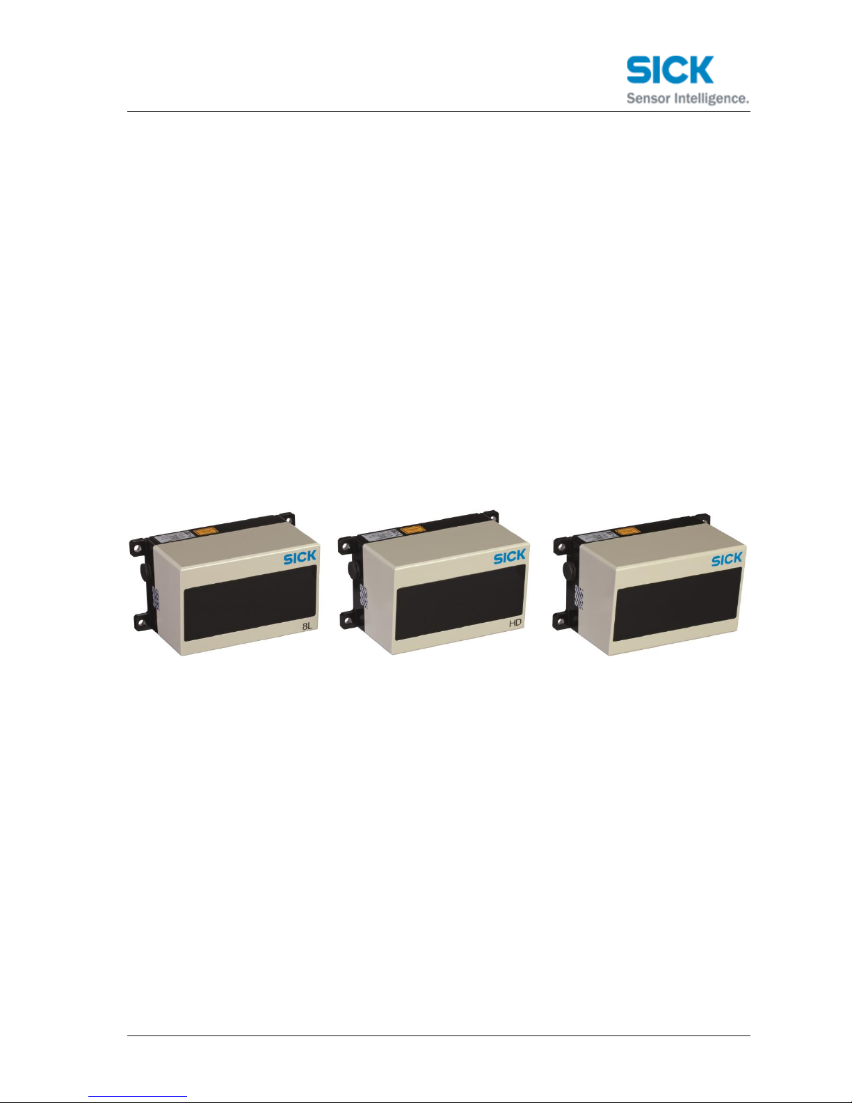
CAN data protocol
LD-MRS 400001S01
LD-MRS 400102S01
LD-MRS 800001S01
Page 2

8014493/ YDB5/2014-11-25 © SICK AG · Germany · All rights reserved · Subject to change without notice Page 2 of 26
Table of Content
1 Introduction 3
2 General information 3
2.1 CAN frame format 3
2.2 Identifiers 3
2.3 Message format 4
3 Object Data 5
3.1 List header: CAN Base ID (e.g. 0x500) 5
3.2 Timestamp: CAN Base ID + 0x1 (e.g. 0x501) 6
3.3 Tracking1: CAN Base ID + 0x2 (e.g. 0x502) 6
3.4 Tracking2: CAN Base ID + 0x3 (e.g. 0x503) 7
3.5 Class and box1: CAN Base ID + 0x4 (e.g. 0x504) 7
3.6 Box2: CAN Base ID + 0x5 (e.g. 0x505) 7
3.7 Contour header: CAN Base ID + 0x6 (e.g. 0x506) 8
3.8 Contour points: CAN Base ID + 0x7 (e.g. 0x507) 8
4 Command Interface 10
4.1 LD-MRS commands and command replies 10
4.1.1 Reset sensor 10
4.1.2 SaveConfig 11
4.1.3 Set Parameter 11
4.1.4 Get Parameter 11
4.1.5 Load Factory Defaults 12
4.1.6 Start Measure 12
4.1.7 Stop Measure 13
4.1.8 SetNTPTimestampSec 13
4.1.9 SetNTPTimestampFracSec 14
4.2 LD-MRS parameter list 15
4.3 Examples 22
5 LD-MRS error/warning 23
1.1 Error register 1 23
1.2 Error register 2 24
1.3 Warning register 1 25
1.4 Warning register 2 25
6 Ego motion information 26
Page 3

8014493/ YDB5/2014-11-25 © SICK AG · Germany · All rights reserved · Subject to change without notice Page 3 of 26
1 Introduction
This document describes how data is received and transmitted via CAN. Addressed
systems are LD-MRS400001S0, LD-MRS400102S01 and LD-MRS800000S01.
This document is based on firmware version 3.02.
Note: The standard LD-MRSXXX (without “S01”) also has a CAN interface. This interface
is used to control the external I/O-extender of the sensor and uses other commands.
This document does not apply to this sensor type!
2 General information
2.1 CAN frame format
The LD-MRS uses CAN 2.0A with 11-bit identifiers. The baudrate is 500 kBit/s.
2.2 Identifiers
Each CAN messages has an identifier (ID). For the LD-MRS, a base ID can be set as a
parameter (default is 0x500). This base ID defines a range of 16 subsequent IDs, starting
with the base ID itself. E.g., with the base ID set to 0x500, the used CAN messages will
have the IDs 0x500 through 0x50F.
As the message ID defines the message and its contents, each ID may only be used by
one device (or for one purpose) on the CAN bus. If multiple sensors should be used on
one CAN bus, each sensor must have a base ID that separates its ID range from the
other devices.
Table 1: CAN ID overview
CAN ID
Default ID
Description
0x303 –
0x306
(fixed)
Vehicle motion data
base ID
0x500
Object list header (start of object data)
base ID+1
0x501
Object timestamp
base ID+2
0x502
Tracking1: First set of information for an object
base ID+3
0x503
Tracking2: Second set of information for an object
base ID+4
0x504
Class and box1: Bounding box information for an
object
base ID+5
0x505
Box2: Bounding box information for an object
base ID+6
0x506
Contour header: Start of contour information for an
object
base ID+7
0x507
Contour points: Additional contour points.
base ID+8
0x508
Object list trailer
base ID+9
0x509
(unused)
base ID+10
0x50A
Command to the sensor.
base ID+11
0x50B
Reply from the sensor (for each received
Page 4

8014493/ YDB5/2014-11-25 © SICK AG · Germany · All rights reserved · Subject to change without notice Page 4 of 26
command).
base ID+12
0x50C
(unused)
base ID+13
0x50D
(unused)
base ID+14
0x50E
(unused)
base ID+15
0x50F
Error messages
2.3 Message format
Message length is always 8 bytes, unless declared differently in the description.
Message byte and bit numbering is zero based. E.g., the first data byte of a message ist
byte 0, the last one byte 7.
Data encoding is big endian (Motorola) for all messages except command, command
reply and errors and warnings, which use little endian (Intel).
Page 5

8014493/ YDB5/2014-11-25 © SICK AG · Germany · All rights reserved · Subject to change without notice Page 5 of 26
3 Object Data
Object data can be transmitted via CAN if the corresponding output flag is enabled in the
sensor.
The ID range is CAN base ID … CAN base ID + 0x7, first and last ID included.
For a base ID 0x500 the range is [0x500, 0x507].
One set of object data consist of:
A list header message
A timestamp message
For each object:
o A Tracking1 message
o A Tracking2 message
o A Class and box1 message
o A Box2 message
o A contour header message
o For each next 1-3 contour points:
A Contour point message
Note: Data encoding is Big Endian format.
3.1 List header: CAN Base ID (e.g. 0x500)
Content
Data area
Data type
Description
Version
byte 0
UINT8
Version of the object data format. This
document describes version 1.
Number of objects
byte 1
UINT8
Number of objects transmitted in this
cycle.
View range
estimation
byte 2
UINT8
Estimated maximum sensor view range
on typical vehicles in percent [0,100].
100: full view range
0: low view range
0xFF: invalid (no estimation possible)
Sensor
temperature
byte 3
INT8
Current sensor temperature in °C. 0x80
indicates an invalid value.
Object data info
flags
byte 4
bit field
8 bits
bit 0: Velocity type
0 = absolute velocities,
1 = relative velocities.
bit 1: Bounding boxes
0 = boxes are object boxes (aligned to
object),
1 = boxes are bounding boxes (aligned
to axes of coordinate system).
bits 2…7:
reserved
Page 6

8014493/ YDB5/2014-11-25 © SICK AG · Germany · All rights reserved · Subject to change without notice Page 6 of 26
Counter
byte 5
UINT8
Counter for header and trailer message
(to be able to match header and trailer)
Blindness
byte 6
UINT8
0: sensor not covered; other: sensor
covered = blind
Unused
byte 7
-
-
3.2 Timestamp: CAN Base ID + 0x1 (e.g. 0x501)
Content
Data area
Data type
Description
NTP seconds
bytes 0…3
UINT32
Start time of the scan these objects are
based on.
NTP fractional
seconds
byte 4…7
UINT32
Fractional seconds the scan start time.
3.3 Tracking1: CAN Base ID + 0x2 (e.g. 0x502)
Content
Data area
Data type
Description
Object ID
byte 0
UINT8
ID of this object from the tracking. Use
this ID to refer messages to an object.
Position x
bytes 1…2
INT16
Position of the object (reference point,
e.g. center of gravity) in the reference
coordinate system in cm.
Position y
bytes 3…4
INT16
Velocity x
byte 5
bits 0…7,
byte 6
bits 4…7
INT12
Object velocity in 0.1 m/s in the reference
coordinate system. See list header for
absolute or relative velocities. 0x800
indicates an invalid velocity.
Velocity y
byte 6
bits 0…3,
byte 7
bits 0…7
INT12
Please refer to this image for clarification of the bits and bytes used for each information:
Byte 7 6 5 4 3 2 1 0
0
1
2
3
4
5 Velocity X
6
7 Velocity Y
Bit
Object ID
Position X
Position Y
Page 7

8014493/ YDB5/2014-11-25 © SICK AG · Germany · All rights reserved · Subject to change without notice Page 7 of 26
3.4 Tracking2: CAN Base ID + 0x3 (e.g. 0x503)
Content
Data area
Data type
Description
Object ID
byte 0
UINT8
ID of this object from the tracking. Use
this ID to refer messages to an object.
Object age
byte 1
UINT8
Number of scans this object has been
tracked for. Saturates at 0xFF.
Object prediction
age
byte 2
UINT8
Number of scans this object has only be
predicted without measurement update.
Saturates at 0xFF. Is reset to 0 after
measurement update.
Object time offset
byte 3
UINT8
Detection time of this object as offset to
the reference time stamp in ms.
Position x sigma
byte 4
UINT8
Standard deviation of the position
estimation in cm.
Position y sigma
byte 5
UINT8
Velocity x sigma
byte 6
UINT8
Standard deviation of the velocity
estimation in cm.
Velocity y sigma
byte 7
UINT8
3.5 Class and box1: CAN Base ID + 0x4 (e.g. 0x504)
Content
Data area
Data type
Description
Object ID
byte 0
UINT8
ID of this object from the tracking. Use
this ID to refer messages to an object.
reserved
byte 1
UINT8
reserved
reserved
byte 2
UINT8
reserved
reserved
byte 3
UINT8
reserved
Box center x
bytes 4…5
INT16
Center position of the box in cm. See list
header for object box / bounding box.
Box center y
bytes 6…7
INT16
3.6 Box2: CAN Base ID + 0x5 (e.g. 0x505)
Content
Data area
Data type
Description
Object ID
byte 0
UINT8
ID of this object from the tracking. Use
this ID to refer messages to an object.
Box size x
bytes 1…2
UINT16
Size of the box in cm in the object
coordinate system. The box orientation is
only available for an object box. A
bounding box is an unrotated rectangle in
the reference coordinate system. In this
case the box size is always given in the
reference coordinate system. 0x8000
indicates an invalid orientation.
Box size x
bytes 3…4
UINT16
Page 8

8014493/ YDB5/2014-11-25 © SICK AG · Germany · All rights reserved · Subject to change without notice Page 8 of 26
Box orientation
byte 5…6
INT16
Object box orientation in the reference
coordinate system in 1/100°. 0x8000
indicates an invalid orientation.
Reserved
byte 7
-
-
3.7 Contour header: CAN Base ID + 0x6 (e.g. 0x506)
Content
Data area
Data type
Description
Object ID
byte 0
UINT8
ID of this object from the tracking. Use
this ID to refer messages to an object.
Number of contour
points
byte 1
UINT8
Number of contour points including start
point transmitted for this object. The
number of following ObjectDataContour
messages can be calculated by
(NumOfContourPoints+1) Div 3. If this
value is set to 0xFF (invalid), the contour
of this object was not calculated correctly
(e.g. too many contour points). In this
case, the ContourStartpoint contains the
closest distance to the object. No more
contour point messages are sent for this
object.
Closest contour
point number
byte 2
UINT8
The closest object distance can be found
in the contour point with this number. The
numbering starts with 0 (start point).
Reserved
byte 3
-
-
Start point x
bytes 4…5
INT16
Position of the first contour point in cm in
the reference coordinate system. This is
the first point of the contour (or the
closest distance, see above). The
following contour points are only given by
offsets to the previous points.
Start point y
bytes 6…7
INT16
3.8 Contour points: CAN Base ID + 0x7 (e.g. 0x507)
Content
Data area
Data type
Description
Object ID
byte 0
UINT8
ID of this object from the tracking. Use
this ID to refer messages to an object.
Contour message
number
byte 1
UINT8
Number of this contour message. Zero
based.
x offset
(e.g. point 1)
byte 2
INT8
Add these offsets to the position of the
previous point. Calculate the position for
Page 9

8014493/ YDB5/2014-11-25 © SICK AG · Germany · All rights reserved · Subject to change without notice Page 9 of 26
y offset
(e.g. point 1)
byte 3
INT8
each contour point (besides the start
point) using the offsets.
First contour point is the start point sent
in the contour header message.
Note that these offsets have a resolution
of 4 cm. Multiply these values by 4 to
convert to cm.
x offset
(e.g. point 2)
byte 4
INT8
y offset
(e.g. point 2)
byte 5
INT8
x offset
(e.g. point 3)
byte 6
INT8
y offset
(e.g. point 3)
byte 7
INT8
3.9 List trailer: CAN Base ID (e.g. 0x508)
Content
Data area
Data type
Description
Number of object
CAN messages
sent
byte 0 - 1
UINT16
Number of CAN messages sent for the
current object list.
NumOfWarningErr
orMessagesSent
byte 2
UINT8
Number of warning/error messages sent
since the last object list trailer:
Counter
byte 3
UINT8
Counter for header and trailer message
(to be able to match header and trailer)
Unused
byte 4 - 7
-
-
Page 10

8014493/ YDB5/2014-11-25 © SICK AG · Germany · All rights reserved · Subject to change without notice Page 10 of 26
4 Command Interface
Commands can be transmitted via CAN.
The ID is CAN base ID + 0xA. Example: For a base ID 0x500 the command ID is 0x50A.
Attention: The data is encoded in little endian byte order in this message!
Content
Data area
Data type
Description
Command ID
bytes 0…1
UINT16
See detailed list of commands and
according options/parameters.
Command data
bytes 2…7
-
Depending on command. May be unused
for some commands.
After receiving a command a reply is always sent.
The ID is CAN base ID + 0xB. Example: For a base ID 0x500 the command ID is 0x50B.
Attention: The data is encoded in little endian byte order in this message!
Content
Data area
Data type
Description
Reply ID
bytes 0…1
UINT16
If a command succeeded, the reply ID is
equal to the corresponding command ID.
If a command failed, the reply ID is the
command ID + 0x8000. Thus, the most
significant bit indicates a failed
command.
Command data
bytes 2…7
-
Depending on command this reply is
related to. May be completely unused for
some replies and if a command failed.
4.1 LD-MRS commands and command replies
4.1.1 Reset sensor
Bytes
Offset
LD-MRS command:
content
Content type
Description
2 0 0x0000
UINT16
Reset DSP
Restarts the sensor. For this command, no reply is sent.
Example: Reset the sensor.
Send the message ID=0x50A, DLC=2, Data=00 00. This will immediately reset the
sensor. Note that no reply is sent from the sensor.
Page 11

8014493/ YDB5/2014-11-25 © SICK AG · Germany · All rights reserved · Subject to change without notice Page 11 of 26
4.1.2 SaveConfig
Bytes
Offset
LD-MRS command:
content
Content type
Description
2 0 0x0004
UINT16
Current sensor configuration
will be saved permanently.
Multiple SetParameter
commands may be sent
before saving the changes
permanently.
The command SaveConfig will be acknowledged by the same command ID without
command reply data.
4.1.3 Set Parameter
Bytes
Offset
LD-MRS command:
content
Content type
Description
2 0 0x0010
UINT16
Set a single Parameter by its
index to the sensor memory.
Parameter is set only
temporarily until a SaveConfig
command (see 4.1.2) is sent.
2 2 Parameter index
UINT16
Refer to LD-MRS parameter
list.
4 4 Parameter
UINT32
Set parameter accordingly to
parameter list. If e.g. a 2 byte
value is set, use the first 2
bytes. Fill the remaining 2
bytes with 0.
The command Set Parameter will be acknowledged by the same command ID without
any command reply data.
4.1.4 Get Parameter
Bytes
Offset
LD-MRS command:
content
Content type
Description
2 0 0x0011
UINT16
Read a single Parameter with
its index from the LD-MRS.
2 2 Parameter index
UINT16
Refer to LD-MRS parameter
list (4.2)
Page 12

8014493/ YDB5/2014-11-25 © SICK AG · Germany · All rights reserved · Subject to change without notice Page 12 of 26
Bytes
Offset
LD-MRS reply: content
Content type
Description
2 0 0x0011
UINT16
Read a single Parameter by
its index from the LD-MRS.
2 2 Parameter index
UINT16
Refer to LD-MRS parameter
list (4.2)
4 4 Parameter
UINT32
Example: Read the data output flags.
Send the message ID=0x50A, DLC=4, Data=11 00 12 10.
Answer from the sensor is ID=050B, DLC=8, Data=11 00 12 10 80 00 00 00.
Note that the two bold numbers can vary as they are the requested parameter.
4.1.5 Load Factory Defaults
Bytes
Offset
LD-MRS command:
content
Content type
Description
2 0 0x001A
UINT16
Resets all parameters to the
factory defaults.
The command Load Factory Defaults will be acknowledged by the same command
ID without any command reply data.
Example: Send the message ID=0x50A, DLC=2, Data=1A 00. Reply from the sensor is
the message ID=0x50B, DLC=8, Data=1A 00 00 00 00 00 00 00.
4.1.6 Start Measure
Bytes
Offset
LD-MRS command:
content
Content type
Description
2 0 0x0020
UINT16
Starts the measurement with
the current settings.
The command Start Measure will be acknowledged by the same command ID without
any command reply data.
Example: Send the message ID=0x50A, DLC=2, Data=20 00. Reply from the sensor is
the message ID=0x50B, DLC=8, Data=20 00 00 00 00 00 00 00.
Page 13

8014493/ YDB5/2014-11-25 © SICK AG · Germany · All rights reserved · Subject to change without notice Page 13 of 26
4.1.7 Stop Measure
Bytes
Offset
LD-MRS command:
content
Content type
Description
2 0 0x0021
UINT16
Stops the measurement.
The command Stop Measure will be acknowledged by the same command ID without
any command reply data.
Example: Send the message ID=0x50A, DLC=2, Data=21 00. Reply from the sensor is
the message ID=0x50B, DLC=8, Data=21 00 00 00 00 00 00 00.
4.1.8 SetNTPTimestampSec
Bytes
Offset
LD-MRS command:
content
Content type
Description
2 0 0x0030
UINT16
sets the second of
NTPtimestamp.
2 2 Reserved0
UINT16
-
4 4 Timestamp
UINT32
Seconds (NTP format). The
time will be set in the sensor
when the fractional seconds
command is received (see 0).
The command SetNTPTimestampSec will be acknowledged by the same command ID
without any command reply data.
Example: To set the NTP-Seconds to 0x12345678, send the message ID=0x50A,
DLC=8, Data=30 00 00 00 78 56 34 12. Reply from the sensor is the message
ID=0x50B, DLC=8, Data=30 00 00 00 00 00 00 00.
Note that in order to set the time, you must send the fractional seconds with the
command SetNTPTimestampFracSec command next!
Page 14

8014493/ YDB5/2014-11-25 © SICK AG · Germany · All rights reserved · Subject to change without notice Page 14 of 26
4.1.9 SetNTPTimestampFracSec
Attention: Before this command can be executed, first command
"SetNTPTimestampSec” (0x0030) must be sent (see 4.1.8)!
Bytes
Offset
LD-MRS command:
content
Content type
Description
2 0 0x0031
UINT16
sets the fractional second of
NTPtimestamp.
2 2 Reserved0
UINT16
-
4 4 Timestamp
UINT32
Fractional seconds (NTP
format).
The command SetNTPTimestampFracSec will be acknowledged by the same command
ID without any command reply data.
Page 15

8014493/ YDB5/2014-11-25 © SICK AG · Germany · All rights reserved · Subject to change without notice Page 15 of 26
4.2 LD-MRS parameter list
This table gives an overview of available LD-MRS parameters. Please refer to 4.1.3 and
4.1.4 for details on getting and setting these parameters.
IP address, subnet mask and standard gateway encode the data as UINT32 value which
is built like that: aa.bb.cc.dd = 0xaabbccdd. Due to little endian byte order this value must
be sent as 0xddccbbaa.
Bytes
Parameter
index
LD-MRS parameter
datatype
Description
4
0x1000
IP address
UINT32
Valid: all
2
0x1001
TCP Port
UINT32
Valid: all
4
0x1002
Subnet Mask
UINT32
Valid: all
4
0x1003
Standard gateway
UINT32
Valid: all
4
0x1010
CAN Base ID
UINT32
Valid: value <= 0x7F0
2
0x1011
CAN Baud Rate
UINT16
in kBaud - next matching
value (1000 kBaud, 500
kBaud, 250 kBaud, 125
kBaud) will be used.
2
0x1012
Data Output Flag
16 bit field
Bit true: disable output,
false: enable output.
0xFFFF is invalid.
bit0: ETH scan data
bit1: reserved/internal
bit2: ETH object data
bit3: ETH vehicle data
bit4: ETH errors/warnings
bit5: CAN errors/warnings
bit6: CAN object data
bit7...15: reserved
2
0x1013
maxObjectsViaCAN
UINT16
<= 65 (max. number of
objects) limited by tracking
and CAN bus capacity.
2
0x1014
ContourPointDensity
UINT16
Valid: < 3
0: closest point only
1: low density
2: high density
2
0x1015
ObjectPriorizationCrit
erion
UINT16
Valid: < 2
Used to reduce transmitted
objects via CAN. Decision
which objects are
discarded is based on this
criterion.
0: Radial
1: Look ahead
Page 16

8014493/ YDB5/2014-11-25 © SICK AG · Germany · All rights reserved · Subject to change without notice Page 16 of 26
Bytes
Parameter
index
LD-MRS parameter
datatype
Description
2
0x1016
CAN object data
options
16 bit field
Valid: all
bit 0: 0 = absolute
velocities, 1 = relative
velocities
bit 1: 0 = boxes are object
boxes, 1 = boxes are
bounding boxes
bits 2…15: reserved
2
0x1017
Minimum Object Age
UINT16
Valid: all
Minimum tracking age
(number of scans) of an
object to be transmitted.
2
0x1018
Maximum Prediction
Age
UINT16
Valid: all
Maximum prediction age
(number of scans) of an
object to be transmitted.
2
0x1100
Start angle
INT16
In 1/32°, in the sensor
coordinate system.
Valid: 1600…-1919.
Start angle > end angle!
2
0x1101
End angle
INT16
In 1/32°, in the sensor
coordinate system.
Valid: 1599…-1920.
Start angle > end angle!
2
0x1102
Scan frequency
UINT16
In 1/256 Hz.
Valid:
3200 (12.5 Hz)
6400 (25.0 Hz)
12800 (50.0 Hz)
2
0x1103
Sync angle offset
INT14 (!)
(16 bits
transferred)
In 1/32° in the sensor
coordinate system.
Valid: -5760…+5759
(-180°…+180°).
Bits 14 and 15 are ignored!
2
0x1104
angular resolution
type
UINT16
0: focused
1: constant
2: reserved
2
0x1105
angleTicksPerRotati
on
UINT16
11520 (read only),
constant for LD-MRS
2
0x1108
RangeReduction
UINT16
Available for
LDMRS800001.S01 only
0: full sensitivity (default)
1: lower 4 layers reduced
2: upper 4 layers reduced
3: both reduced
Page 17

8014493/ YDB5/2014-11-25 © SICK AG · Germany · All rights reserved · Subject to change without notice Page 17 of 26
Bytes
Parameter
index
LD-MRS parameter
datatype
Description
2
0x1109
Upside down mode
UINT16
Available for
LDMRS800001.S01 only
0: device not in upside
down mode (default)
1: upside down mode
active
2
0x110A
Ignore near range
UINT16
Available for
LDMRS800001.S01 only
0: do not ignore points in
near range (up to 15m)
(default)
1: ignore points in near
range if 0x1108 is 1
2
0x110B
Sensitivity control
active
UITN16
0: not active (default)
1: Sensitivity will be
reduced dynamically up to
60% in case of direct sun
light.
2
0x1200
SensorMounting_X
INT16
In cm, related to vehicle
reference point, rear axle.
Order of translation and
rotation is essential
(Rotation -> Translation).
2
0x1201
SensorMounting_Y
INT16
In cm, related to vehicle
reference point, rear axle.
Order of translation and
rotation is essential
(Rotation -> Translation).
2
0x1202
SensorMounting_Z
INT16
In cm, related to vehicle
reference point, rear axle.
Order of translation and
rotation is essential
(Rotation -> Translation).
2
0x1203
SensorMounting_Ya
w
INT16
In 1/32°, order of
translation and rotation is
essential (Yaw->Pitch>Roll-> Translation).
2
0x1204
SensorMounting_Pit
ch
INT16
In 1/32°, order of
translation and rotation is
essential (Yaw->Pitch>Roll-> Translation).
Page 18

8014493/ YDB5/2014-11-25 © SICK AG · Germany · All rights reserved · Subject to change without notice Page 18 of 26
Bytes
Parameter
index
LD-MRS parameter
datatype
Description
2
0x1205
SensorMounting_Rol
l
INT16
In 1/32°, order of
translation and rotation is
essential (Yaw->Pitch>Roll-> Translation).
2
0x1206
VehicleFrontToFront
Axle
UINT16
valid: all; in cm
2
0x1207
FrontAxleToRearAxl
e
UINT16
valid: all; in cm
2
0x1208
RearAxleToVehicleR
ear
UINT16
valid: all; in cm
2
0x1209
VehicleWidth
UINT16
Width of the vehicle; valid:
all; in cm.
2
0x120A
steerRatioType
UINT16
Reserved, internal.
4
0x120C
SteerRatioPoly0
Float32
Reserved, internal.
Valid: all
4
0x120D
SteerRatioPoly1
Float32
Reserved, internal.
Valid: all
4
0x120E
SteerRatioPoly2
Float32
Reserved, internal.
Valid: all
4
0x120F
SteerRatioPoly3
Float32
Reserved, internal.
Valid: all
2
0x1210
Vehicle Motion Data
Flags
16 bit field
Reserved, internal.
Bit 0: Vehicle Motion data
expected: 1=true, 0=false
Bits 1 to 15: reserved
2
0x2208
EnableSensorInfo
UINT16
Enable flag for
“SensorInfo”-data. Default
is 0 (disabled). When set
to 1, the sensor sends
SensorInfo data with each
scan.
Please refer to chapter Fehler!
Verweisquelle konnte nicht
gefunden werden. for details.
This setting is non-persistent
and has to be re-activated after
each reboot.
Page 19

8014493/ YDB5/2014-11-25 © SICK AG · Germany · All rights reserved · Subject to change without notice Page 19 of 26
Bytes
Parameter
index
LD-MRS parameter
datatype
Description
2
0x3302
BeamTilt
CompressedR
adian
Beam tilt angle. For
standard devices, this
angle is 0. For 8-layer
devices, this is the tilt of
the scan center in 0°
(forward) direction typically either 1.2° or 1.6°.
For a description of the data
format, see chapter Fehler!
Verweisquelle konnte nicht
gefunden werden..
4
0x3500
Timemeter
UINT32
Current timemeter value, in
[minutes]. This is the
overall power-on-time of
the sensor since
production.
This parameter is read-only.
2
0x3600
Enable APD control
UINT16
Enables adaptive
sensitivity control. If
disabled, sensor works at
maximum sensitivity. Valid
values are 1 (Enabled,
DEFAULT) or 0 (Disabled).
This parameter is not persistent;
it will not be saved in the flash
memory and is set to default
(=enabled) at reboot.
This parameter is available only
in DSP firmware version 2.2.09.
2
0x4000
NumSectors
UINT16
FlexRes feature: Number
of angle sectors. This
defines the number of valid
sectors, set with the
following parameters.
The sensor checks the validity of
the sectors before applying the
configuration. In case of an
error, read parameter 0x7000 for
further information.
2
0x4001
StartAngle, Sector 1
INT16
In 1/32°, in the sensor
coordinate system.
Valid: 1600…-1919.
This is the start angle of
the first sector.
The angular resolution for this
sector is set with parameter
0x4009.
Page 20

8014493/ YDB5/2014-11-25 © SICK AG · Germany · All rights reserved · Subject to change without notice Page 20 of 26
Bytes
Parameter
index
LD-MRS parameter
datatype
Description
2
0x4002
StartAngle, Sector 2
INT16
In 1/32°, in the sensor
coordinate system.
Valid: 1600…-1919.
This is the start angle of
the second sector.
The angular resolution for this
sector is set with parameter
0x400A.
2
0x4003
StartAngle, Sector 3
INT16
…see above.
2
0x4004
StartAngle, Sector 4
INT16
…see above.
2
0x4005
StartAngle, Sector 5
INT16
…see above.
2
0x4006
StartAngle, Sector 6
INT16
…see above.
2
0x4007
StartAngle, Sector 7
INT16
…see above.
2
0x4008
StartAngle, Sector 8
INT16
…see above.
2
0x4009
Angular resolution,
Sector 1
INT16
Angular resolution of first
sector. Valid values are 32
(1.0°), 16 (0.5°), 8 (0.25°)
and 4 (0.125°).
2
0x400A
Angular resolution,
Sector 2
INT16
Angular resolution of
second sector.
2
0x400B
Angular resolution,
Sector 3
INT16
…see above.
2
0x400C
Angular resolution,
Sector 4
INT16
…see above.
2
0x400D
Angular resolution,
Sector 5
INT16
…see above.
2
0x400E
Angular resolution,
Sector 6
INT16
…see above.
2
0x400F
Angular resolution,
Sector 7
INT16
…see above.
2
0x4010
Angular resolution,
Sector 8
INT16
…see above.
Page 21

8014493/ YDB5/2014-11-25 © SICK AG · Germany · All rights reserved · Subject to change without notice Page 21 of 26
Bytes
Parameter
index
LD-MRS parameter
datatype
Description
4
0x7000
Detailed error code
for FlexRes
UINT32
Detailed error information
for FlexRes feature. When
parameter setting of
0x4000 fails, reading this
parameter will give the
reason.
0x006C: The number of shots
per scan is higher than
440.
0x006D: The sectors with a
resolution of 0.125° sum
up to more than 20°.
0x006E: The scan frequency is
not 12.5Hz.
0x006F: The start angles of the
sectors decrease not
strictly monotone.
0x0070: Could not set FlexRes
parameter because the
sensor is not idle and in
flex res mode.
0x0071: The resolution of one
sector is not 4,8,16 or
32 (0.125°, 0.25°, 0.5°,
1°)
0x0072: The number of sectors
is larger than 8
Page 22

8014493/ YDB5/2014-11-25 © SICK AG · Germany · All rights reserved · Subject to change without notice Page 22 of 26
4.3 Examples
This example shows how to set the IP address via CAN to 10.152.36.200.
Bytes
Message ID:
CAN base ID + 0xA
e.g. 0x50A
Content type
Content
0
Command ID: 0x0010
UINT16
0x10
1
0x00
2
Parameter index: 0x1000 (IP Address)
UINT16
0x00
3
0x10
4
Parameter data (here: 10.152.36.200,
resp. 0x0A9824C8)
UINT64
0xC8
5
0x24
6
0x98
7
0x0A
Page 23

8014493/ YDB5/2014-11-25 © SICK AG · Germany · All rights reserved · Subject to change without notice Page 23 of 26
5 LD-MRS error/warning
As soon as a LD-MRS laserscanner detects an error or wants to emit a warning, this
message is sent asynchronously. Errors and warning bits are reset after sending this
message.
This message will be sent periodically as long as errors of warnings persist.
The ID is CAN base ID + 0xF. Example: For a base ID 0x500, the command ID is 0x50F.
This message is encoded in Little Endian format!
Name
Data area
Data type
Description
Error register 1
bytes 0…1
bit field 16
bits
See detailed description below
Error register 2
bytes 2…3
bit field 16
bits
Warning register 1
bytes 4…5
bit field 16
bits
Warning register 2
bytes 6…7
bit field 16
bits
1.1 Error register 1
This register contains error flags from the FPGA of the scanner.
Bytes
Comment
Bit 0
contact support
Bit 1
contact support
Bit 2
scan buffer transmitted incompletely, decrease scan
resolution/frequency/range; contact support
Bit 3
Scan buffer overflow , decrease scan
resolution/frequency/range; contact support
Bit 4
contact support
Bit 5-7
Reserved
Bit8…9
Bit 8: APD Under Temperature, provide heating. This bit
is set when the internal temperature drops below -40°C.
Bit 9: APD Over Temperature, provide cooling. This bit
is set when the internal temperature rises above
+125°C.
Bit 8 and 9: APD Temperature Sensor defect, contact
support
Bit 10
contact support
Bit 11
contact support
Bit 12
contact support
Bit 13
contact support
Bit 14-15
Reserved
Page 24

8014493/ YDB5/2014-11-25 © SICK AG · Germany · All rights reserved · Subject to change without notice Page 24 of 26
1.2 Error register 2
This register contains error flags from the processor of the scanner.
Bytes
Comment
Bit 0
Internal communication error. The DSP did not receive
any scan data from the FPGA. This error typically occurs
if the sensor cannot measure correctly. If the error
persists, contact support.
Bit 1
Internal communication error. The DSP could not
communicate correctly with the FPGA via the control
interface. If the error persists, contact support.
Bit 2
Internal communication error. The DSP did not receive
valid scan data from the FPGA for more than 500 ms.
This error may be caused by the current operating state
(e.g. failure of the motor control due to heavy vibration),
or by an internal defect. If the error persists, contact
support.
Bit 3
contact support
Bit 4
Incorrect configuration data, load correct configuration
values.
Bit 5
Configuration contains incorrect parameters, load correct
configuration values
Bit 6
Data processing timeout, decrease scan resolution or
scan frequency
Bit 7
contact support
Bit 8
Incoming CAN message lost. This is an overflow of the
input buffer, and at least one incoming CAN message
was lost. This error may indicate that the sensor is
flooded with incoming messages. Reduce the number of
messages.
Bit 9
reserved
Bit 10
Severe deviation (> 10%) from expected scan frequency.
This may indicate motor trouble. If error persists, contact
support.
This bit is available in firmware v2.2.09 and 3.02 or newer.
Bit 11
Motor blocked. No rotation of the internal mirror was
detected, and automatic restart has failed. This may
indicate motor trouble. If error persists, contact support.
This bit is available in firmware v2.2.09 and 3.02 or newer.
Bits 1215
reserved
Page 25

8014493/ YDB5/2014-11-25 © SICK AG · Germany · All rights reserved · Subject to change without notice Page 25 of 26
1.3 Warning register 1
This register contains warning flags from the FPGA of the scanner.
Bytes
Comment
Bit0-2
reserved
Bit3
warning of insufficient temperature (“Low temperature”).
This bit is set when the internal temperature drops below
-30°C.
Bit4
warning of exceeding temperature (“High temperature”).
This bit is set when the internal temperature rises above
+115°C.
Bit5-6
reserved
Bit 7
check syncronisation- and scan frequency
Bit
8…15
reserved
1.4 Warning register 2
This register contains warning flags from the processor of the scanner.
Bytes
Comment
Bit0
reserved
Bit1
Ethernet interface blocked, check Ethernet connection
Bit2
reserved
Bit3
contact support
Bit4
Check Ethernet data
Bit5
Incorrect or forbidden command received, check
command
Bit6
Memory access failure, restart LD-MRS, contact support
Bit7..14
Internal warning states:
Bit 7: Segement overflow
Bit 8: EgoMotion
Bit 9: MountingPosition
Bit 10: calculated frequency
Bit 11: no ntp time
Bit 12: no time sync pps
Bit 13: no time sync command
Bit 14: no time sync
Bit 15
Slight deviation from expected scan frequency (5..10%).
This may occur during operation due to vibration or
sensor movement, but may also indicate motor trouble.
This bit is available in Firmware v2.2.09 and 3.02 or newer.
Page 26

8014493/ YDB5/2014-11-25 © SICK AG · Germany · All rights reserved · Subject to change without notice Page 26 of 26
6 Ego motion information
Algorithms working in the LD-MRS are designed to use ego motion information if the
sensor is mounted e.g. on a vehicle. The ego motion data is the data from the vehicle,
e.g. ist speed, that is supplied to the sensor.
Generally this data is not mandatory, but data quality from the sensor will increase if
sensor is moving and reliable ego motion information is supplied via CAN. Data update
rate must be at least the scan frequency of the LD-MRS, but may be higher for better
results.
If vehicle motion data is supplied, it must be sent in the predefined CAN messages
specified below.
Note: Data encoding is Big Endian format.
0x303
Data area
Data type
Description
Version
byte 0
UINT8
Set to 2.
Velocity
bytes 1…2
INT16
Velocity in 0.01 m/s. Two’s complement.
Forward: positive values.
0x304
Data area
Data type
Description
Version
byte 0
UINT8
Set to 2.
Cross acceleration
bytes 1…2
INT16
Cross acceleration in 0.001 m/s². Two’s
complement. To the left: positive values.
0x305
Data area
Data type
Description
Version
byte 0
UINT8
Set to 2.
Steering wheel
angle
bytes 1…2
INT16
Steering wheel angle in 0.001 rad. Two’s
complement. To the left: positive values.
0x306
Data area
Data type
Description
Version
byte 0
UINT8
Set to 2.
Yaw rate
bytes 1…2
INT16
Yaw rate in 0.0001 rad/s. Two’s
complement. To the left: positive values.
 Loading...