

Page 1

D
F
GB
S
LBV 331
-
Tra n sis tor (N PN/ P NP )
B E T R I E B S A N L E I T U N G
Page 2

Inhaltsverzeichnis
Inhaltsverzeichnis
1 Zu diesem Dokument
1.1 Funktion. . . . . . . . . . . . . . . . . . . . . . . . . . . . . . . . . .
1.2 Zielgruppe . . . . . . . . . . . . . . . . . . . . . . . . . . . . . . . .
1.3 Verwendete Symbolik . . . . . . . . . . . . . . . . . . . . . . . .
2 Zu Ihrer Sicherheit
2.1 Autorisiertes Personal. . . . . . . . . . . . . . . . . . . . . . . .
2.2 Bestimmungsgemäße Verwendung . . . . . . . . . . . . . .
2.3 Warnung vor Fehlgebrauch . . . . . . . . . . . . . . . . . . . .
2.4 Allgemeine Sicherheitshinweise. . . . . . . . . . . . . . . . .
2.5 Sicherheitskennzeichen am Gerät . . . . . . . . . . . . . . .
2.6 CE-Konformität. . . . . . . . . . . . . . . . . . . . . . . . . . . . .
2.7 Sicherheitshinweise für Ex-Bereiche . . . . . . . . . . . . .
3 Produktbeschreibung
3.1 Aufbau. . . . . . . . . . . . . . . . . . . . . . . . . . . . . . . . . . .
3.2 Arbeitsweise . . . . . . . . . . . . . . . . . . . . . . . . . . . . . .
3.3 Bedienung . . . . . . . . . . . . . . . . . . . . . . . . . . . . . . . .
3.4 Lagerung und Transport . . . . . . . . . . . . . . . . . . . . . .
4 Montieren
4.1 Allgemeine Hinweise . . . . . . . . . . . . . . . . . . . . . . . .
4.2 Montagehinweise . . . . . . . . . . . . . . . . . . . . . . . . . . .
5 An die Spannungsversorgung anschließen
5.1 Anschluss vorbereiten. . . . . . . . . . . . . . . . . . . . . . . .
5.2 Anschlussschritte . . . . . . . . . . . . . . . . . . . . . . . . . . .
5.3 Anschlussplan Einkammergehäuse . . . . . . . . . . . . . .
5.4 Anschlussplan - Ausführung IP 66/IP 68, 1 bar. . . . . .
4
4
4
5
5
5
5
6
6
6
7
8
8
9
10
11
15
15
16
18
6 In Betrieb nehmen
6.1 Allgemein. . . . . . . . . . . . . . . . . . . . . . . . . . . . . . . . .
6.2 Bedienelemente . . . . . . . . . . . . . . . . . . . . . . . . . . . .
6.3 Funktionstabelle . . . . . . . . . . . . . . . . . . . . . . . . . . . .
7 Instandhalten und Störungen beseitigen
7.1 Wartung. . . . . . . . . . . . . . . . . . . . . . . . . . . . . . . . . .
7.2 Störungen beseitigen . . . . . . . . . . . . . . . . . . . . . . . .
7.3 Elektronikeinsatz tauschen . . . . . . . . . . . . . . . . . . . .
7.4 Das Gerät reparieren . . . . . . . . . . . . . . . . . . . . . . . .
8 Ausbauen
8.1 Ausbauschritte . . . . . . . . . . . . . . . . . . . . . . . . . . . . .
8.2 Entsorgen . . . . . . . . . . . . . . . . . . . . . . . . . . . . . . . .
9 Anhang
9.1 Technische Daten . . . . . . . . . . . . . . . . . . . . . . . . . .
9.2 Maße. . . . . . . . . . . . . . . . . . . . . . . . . . . . . . . . . . . .
2 LBV 331 • - Transistor (NPN/PNP)
19
19
20
22
22
23
24
25
25
26
30
39165-DE-110617
Page 3

Inhaltsverzeichnis
Sicherheitshinweise für Ex-Bereiche
Beachten Sie bei Ex-Anwendungen die Ex-spezifischen Sicherheitshinweise. Diese sind Bestandteil der Betriebsanleitung und liegen
jedem Gerät mit Ex-Zulassung bei.
Redaktionsstand: 2011-06-17
39165-DE-110617
LBV 331 • - Transistor (NPN/PNP) 3
Page 4

1 Zu diesem Dokument
1 Zu diesem Dokument
1.1 Funktion
Die vorliegende Betriebsanleitung liefert Ihnen die erforderlichen
Informationen für Montage, Anschluss und Inbetriebnahme sowie
wichtige Hinweise für Wartung und Störungsbeseitigung. Lesen Sie
diese deshalb vor der Inbetriebnahme und bewahren Sie sie als
Produktbestandteil in unmittelbarer Nähe des Gerätes jederzeit
zugänglich auf.
1.2 Zielgruppe
Diese Betriebsanleitung richtet sich an ausgebildetes Fachpersonal.
Der Inhalt dieser Anleitung muss dem Fachpersonal zugänglich
gemacht und umgesetzt werden.
1.3 Verwendete Symbolik
Information, Tipp, Hinweis
Dieses Symbol kennzeichnet hilfreiche Zusatzinformationen.
Vorsicht: Bei Nichtbeachten dieses Warnhinweises können
Störungen oder Fehlfunktionen die Folge sein.
Warnung: Bei Nichtbeachten dieses Warnhinweises kann ein Perso-
nenschaden und/oder ein schwerer Geräteschaden die Folge sein.
Gefahr: Bei Nichtbeachten dieses Warnhinweises kann eine ernst-
hafte Verletzung von Personen und/oder eine Zerstörung des Gerätes
die Folge sein.
Ex-Anwendungen
Dieses Symbol kennzeichnet besondere Hinweise für Ex-Anwendungen.
l Liste
Der vorangestellte Punkt kennzeichnet eine Liste ohne zwingende
Reihenfolge.
à Handlungsschritt
Dieser Pfeil kennzeichnet einen einzelnen Handlungsschritt.
1 Handlungsfolge
Vorangestellte Zahlen kennzeichnen aufeinander folgende Handlungsschritte.
4 LBV 331 • - Transistor (NPN/PNP)
39165-DE-110617
Page 5

2 Zu Ihrer Sicherheit
2 Zu Ihrer Sicherheit
2.1 Autorisiertes Personal
Sämtliche in dieser Betriebsanleitung beschriebenen Handhabungen
dürfen nur durch ausgebildetes und vom Anlagenbetreiber autorisiertes Fachpersonal durchgeführt werden.
Bei Arbeiten am und mit dem Gerät ist immer die erforderliche
persönliche Schutzausrüstung zu tragen.
2.2 Bestimmungsgemäße Verwendung
Der LBV 331 ist ein Sensor zur Grenzstanderfassung.
Detaillierte Angaben zum Einsatzbereich finden Sie im Kapitel
"Produktbeschreibung".
Die Betriebssicherheit des Gerätes ist nur bei bestimmungsgemäßer
Verwendung entsprechend den Angaben in der Betriebsanleitung
sowie in den evtl. ergänzenden Anleitungen gegeben.
Eingriffe über die in der Betriebsanleitung beschriebenen Hand-
habungen hinaus dürfen aus Sicherheits- und Gewährleistungsgründen nur durch vom Hersteller autorisiertes Personal vorgenommen
werden. Eigenmächtige Umbauten oder Veränderungen sind ausdrücklich untersagt.
2.3 Warnung vor Fehlgebrauch
Bei nicht sachgerechter oder nicht bestimmungsgemäßer Verwendung können von diesem Gerät anwendungsspezifische Gefahren
ausgehen, so z. B. ein Überlauf des Behälters oder Schäden an
Anlagenteilen durch falsche Montage oder Einstellung.
2.4 Allgemeine Sicherheitshinweise
Das Gerät entspricht dem Stand der Technik unter Beachtung der
üblichen Vorschriften und Richtlinien. Durch den Anwender sind die
Sicherheitshinweise in dieser Betriebsanleitung, die landesspezifi-
schen Installationsstandards sowie die geltenden Sicherheitsbestimmungen und Unfallverhütungsvorschriften zu beachten.
Das Gerät darf nur in technisch einwandfreiem und betriebssicheren
Zustand betrieben werden. Der Betreiber ist für den störungsfreien
Betrieb des Gerätes verantwortlich.
Der Betreiber ist ferner verpflichtet, während der gesamten Einsatz-
dauer die Übereinstimmung der erforderlichen Arbeitssicherheitsmaßnahmen mit dem aktuellen Stand der jeweils geltenden Regelwerke festzustellen und neue Vorschriften zu beachten.
39165-DE-110617
LBV 331 • - Transistor (NPN/PNP) 5
Page 6

2 Zu Ihrer Sicherheit
2.5 Sicherheitskennzeichen am Gerät
Die auf dem Gerät angebrachten Sicherheitskennzeichen und hinweise sind zu beachten.
2.6 CE-Konformität
Dieses Gerät erfüllt die gesetzlichen Anforderungen der zutreffenden
EG-Richtlinien. Mit der Anbringung des CE-Zeichens bestätigen wir
die erfolgreiche Prüfung.
2.7 Sicherheitshinweise für Ex-Bereiche
Beachten Sie bei Ex-Anwendungen die Ex-spezifischen Sicherheitshinweise. Diese sind Bestandteil der Betriebsanleitung und liegen
jedem Gerät mit Ex-Zulassung bei.
6 LBV 331 • - Transistor (NPN/PNP)
39165-DE-110617
Page 7

3 Produktbeschreibung
1
2
3
3.1 Aufbau
3 Produktbeschreibung
Lieferumfang
Komponenten
Der Lieferumfang besteht aus:
l Grenzstandsensor LBV 331
l Dokumentation
- Dieser Betriebsanleitung
- Ex-spezifischen "Sicherheitshinweisen" (bei Ex-Ausführun-
gen)
- Ggf. weiteren Bescheinigungen
Der LBV 331 besteht aus den Komponenten:
l Gehäusedeckel
l Gehäuse mit Elektronik
l Prozessanschluss mit Schwingstab
Abb. 1: LBV 331 - mit Kunststoffgehäuse
1 Gehäusedeckel
2 Gehäuse mit Elektronik
3 Prozessanschluss
Typschild
Das Typschild enthält die wichtigsten Daten zur Identifikation und zum
Einsatz des Gerätes:
l Artikelnummer
l Seriennummer
l Technische Daten
l Artikelnummern Dokumentation
Zusätzlich zum Typschild außen am Gerät finden Sie die Seriennummer auch im Inneren des Gerätes.
39165-DE-110617
LBV 331 • - Transistor (NPN/PNP) 7
Page 8

3 Produktbeschreibung
3.2 Arbeitsweise
Einsatzbereich
Funktionsprinzip
Der LBV 331 ist ein Grenzstandsensor mit Schwingstab zur
Grenzstanderfassung.
Er ist konzipiert für industrielle Einsätze in allen Bereichen der
Verfahrenstechnik und wird vorzugsweise in Schüttgütern eingesetzt.
Typische Anwendungen sind Überlauf- und Trockenlaufschutz. Durch
sein einfaches und robustes Messsystem lässt sich der LBV 331
nahezu unabhängig von den chemischen und physikalischen Eigenschaften des Schüttgutes einsetzen.
Er arbeitet auch unter starken Fremdvibrationen oder bei wechselndem Füllgut.
Feststoffdetektion in Wasser
Wenn Sie den LBV 331 als Gerät zur Feststoffdetektion in Wasser
bestellt haben, ist der Schwingstab auf die Dichte des Wassers
abgeglichen. Bei Bedeckung mit Wasser (Dichte: 1 g/cm³/0.036 lbs/in)
meldet der LBV 331 unbedeckt. Erst wenn das Schwingelement
zusätzlich mit Feststoffen (z. B. Sand, Schlamm, Kies etc.) bedeckt
wird, meldet der Sensor eine Bedeckung.
Funktionsüberwachung
Der Elektronikeinsatz des LBV 331 überwacht kontinuierlich folgende
Kriterien:
l Korrekte Schwingfrequenz
l Leitungsbruch zum Piezoantrieb
Wird eine Funktionsstörung erkannt oder fällt die Spannungsversorgung aus, so nimmt die Elektronik einen definierten Schaltzustand an,
d. h. der Ausgang ist geöffnet (sicherer Zustand).
Der Schwingstab wird piezoelektrisch angetrieben und schwingt auf
seiner mechanischen Resonanzfrequenz von ca. 360 Hz. Wird der
Schwingstab mit Füllgut bedeckt, ändert sich die Schwingamplitude.
Diese Änderung wird vom eingebauten Elektronikeinsatz erfasst und
in einen Schaltbefehl umgewandelt.
Spannungsversorgung
Der LBV 331 ist ein Kompaktgerät, d. h. er kann ohne externe
Auswertung betrieben werden. Die integrierte Elektronik wertet das
Füllstandsignal aus und stellt ein Schaltsignal zur Verfügung. Mit
diesem Schaltsignal können Sie ein nachgeschaltetes Gerät direkt
betätigen (z. B. eine Warneinrichtung, eine SPS, eine Pumpe etc.).
Die Daten für die Spannungsversorgung finden Sie im Kapitel
"Technische Daten".
3.3 Bedienung
In der Werkseinstellung können Füllgüter mit einer Dichte > 0,05 g/cm³
(0.002 lbs/in³) gemessen werden. Bei Füllgütern mit niedriger Dichte
> 0,02 g/cm³ (0.0007 lbs/in³) kann das Gerät angepasst werden.
8 LBV 331 • - Transistor (NPN/PNP)
39165-DE-110617
Page 9

3 Produktbeschreibung
Auf dem Elektronikeinsatz finden Sie folgende Anzeige- und Bedienelemente:
l Kontrollleuchte zur Anzeige des Schaltzustandes (grün/rot)
l Potentiometer zur Anpassung an die Füllgutdichte
l Betriebsartenumschaltung zur Wahl des Schaltzustandes (min./
max.)
3.4 Lagerung und Transport
Verpackung
Transport
Transportinspektion
Lagerung
Lager- und Transport-
temperatur
Ihr Gerät wurde auf dem Weg zum Einsatzort durch eine Verpackung
geschützt. Dabei sind die üblichen Transportbeanspruchungen durch
eine Prüfung nach DIN EN 24180 abgesichert.
Bei Standardgeräten besteht die Verpackung aus Karton, ist umweltverträglich und wieder verwertbar. Der Messfühler ist zusätzlich mit
einer Schutzkappe aus Pappe versehen. Bei Sonderausführungen
wird zusätzlich PE-Schaum oder PE-Folie verwendet. Entsorgen Sie
das anfallende Verpackungsmaterial über spez ialisierte Recyclingbetriebe.
Der Transport muss unter Berücksichtigung der Hinweise auf der
Transportverpackung erfolgen. Nichtbeachtung kann Schäden am
Gerät zur Folge haben.
Die Lieferung ist bei Erhalt unverzüglich auf Vollständigkeit und
eventuelle Transportschäden zu untersuchen. Festgestellte Transportschäden oder verdeckte Mängel sind entsprechend zu behandeln.
Die Packstücke sind bis zur Montage verschlossen und unter
Beachtung der außen angebrachten Aufstell- und Lagermarkierungen
aufzubewahren.
Packstücke, sofern nicht anders angegeben, nur unter folgenden
Bedingungen lagern:
l Nicht im Freien aufbewahren
l Trocken und staubfrei lagern
l Keinen aggressiven Medien aussetzen
l Vor Sonneneinstrahlung schützen
l Mechanische Erschütterungen vermeiden
l Lager- und Transporttemperatur siehe Kapitel "Anhang - Techni-
sche Daten - Umgebungsbedingungen"
l Relative Luftfeuchte 20 … 85 %
39165-DE-110617
LBV 331 • - Transistor (NPN/PNP) 9
Page 10

4 Montieren
4 Montieren
4.1 Allgemeine Hinweise
Eignung für die Prozessbedingungen
Schaltpunkt
Feuchtigkeit
Stellen Sie sicher, dass sämtliche, im Prozess befindlichen Teile des
Gerätes, insbesondere Sensorelement, Prozessdichtung und Pro-
zessanschluss für die auftretenden Prozessbedingungen geeignet
sind. Dazu zählen insbesondere Prozessdruck, Prozesstemperatur
sowie die chemischen Eigenschaften der Medien.
Die Angaben dazu finden Sie im Kapitel "Technische Daten" bzw. auf
dem Typschild.
Grundsätzlich kann der LBV 331 in jeder beliebigen Lage eingebaut
werden. Das Gerät muss lediglich so montiert werden, dass sich das
Schwingelement auf Höhe des gewünschten Schaltpunktes befindet.
Verwenden Sie die empfohlenen Kabel (siehe Kapitel "An die
Spannungsversorgung anschließen") und ziehen Sie die Kabelver-
schraubung fest an.
Sie schützen Ihr Gerät zusätzlich gegen das Eindringen von
Feuchtigkeit, indem Sie das Anschlusskabel vor der Kabelverschrau-
bung nach unten führen. Regen- und Kondenswasser können so
abtropfen. Dies gilt vor allem bei Montage im Freien, in Räumen, in
denen mit Feuchtigkeit zu rechnen ist (z. B. durch Reinigungsprozesse) oder an gekühlten bzw. beheizten Behältern.
Abb. 2: Maßnahmen gegen das Eindringen von Feuchtigkeit
Transport
10 LBV 331 • - Transistor (NPN/PNP)
Halten Sie den LBV 331 nicht am Schwingelement. Insbesondere bei
Flansch- oder Rohrversionen kann der Sensor durch das Gerätege-
wicht beschädigt werden.
Entfernen Sie die Schutzkappe erst unmittelbar vor dem Einbau.
39165-DE-110617
Page 11

4 Montieren
Druck/Vakuum
Handhabung
Rührwerke und Fluidi-
sierung
Bei Über- oder Unterdruck im Behälter müssen Sie den Prozessanschluss abdichten. Prüfen Sie vor dem Einsatz, ob das Dichtungsmaterial gegenüber dem Füllgut und der Prozesstemperatur beständig
ist.
Den maximal zulässigen Druck können Sie dem Kapitel "Technische
Daten" oder dem Typschild des Sensors entnehmen.
Der Vibrationsgrenzschalter ist ein Messgerät und muss entsprechend
behandelt werden. Ein Verbiegen des Schwingelements führt zur
Zerstörung des Gerätes.
Warnung:
Das Gehäuse darf nicht zum Einschrauben verwendet werden! Das
Festziehen kann Schäden an der Drehmechanik des Gehäuses
verursachen.
Verwenden Sie zum Einschrauben den Sechskant oberhalb des
Gewindes.
4.2 Montagehinweise
Rührwerke, anlagenseitige Vibrationen o. Ä. können dazu führen, dass
der Grenzschalter starken seitlichen Kräften ausgesetzt ist. Wählen
Sie aus diesem Grund das Verlängerungsrohr des LBV 331 nicht zu
lang, sondern prüfen Sie, ob statt dessen nicht ein kurzer Grenzschalter seitlich in horizontaler Lage montiert werden kann.
Extreme anlagenseitige Vibrationen und Erschütterungen, z. B. durch
Rührwerke und turbulente Strömungen im Behälter z. B. durch
Fluidisierung können das Verlängerungsrohr des LBV 331 zu
Resonanzschwingungen anregen. Dies führt zu einer erhöhten
Materialbeanspruchung an der oberen Schweißnaht. Wenn eine lange
Rohrversion notwendig ist, können Sie deshalb unmittelbar oberhalb
des Schwingelements eine geeignete Abstützung anbringen, um das
Verlängerungsrohr zu fixieren.
Diese Maßnahme gilt vor allem für Anwendungen im Ex-Bereich. Achten
Sie darauf, dass das Rohr durch diese Maßnahme nicht auf Biegung
beansprucht wird.
Einströmendes Füllgut
39165-DE-110617
LBV 331 • - Transistor (NPN/PNP) 11
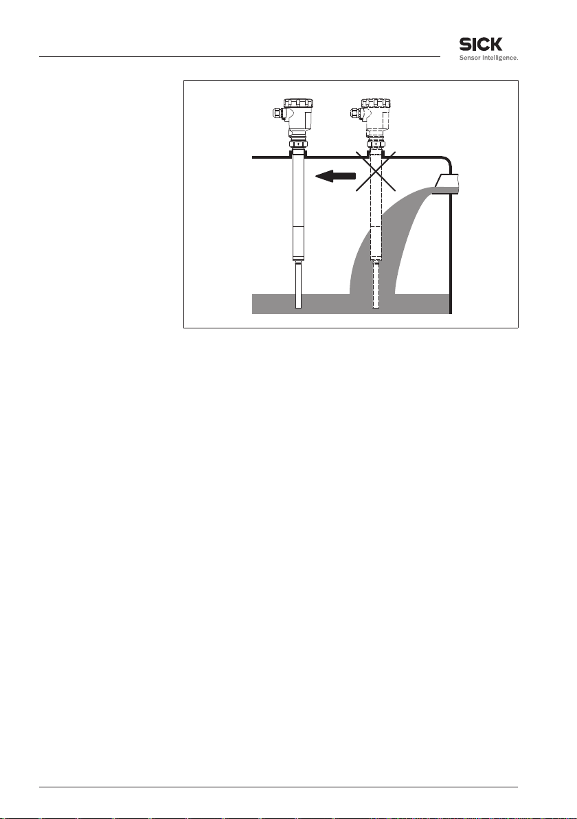
Wenn der LBV 331 im Befüllstrom eingebaut ist, kann dies zu
unerwünschten Fehlmessungen führen. Montieren Sie den LBV 331
deshalb an einer Stelle im Behälter, wo keine störenden Einflüsse, wie
z. B. von Befüllöffnungen, Rührwerken etc. auftreten können.
Dies gilt vor allem für die Gerätetypen mit langem Verlängerungsrohr.
Page 12
4 Montieren
Abb. 3: Einströmendes Füllgut
Arretierverschraubung
Stutzen
Schüttkegel
Der LBV 331 kann zur stufenlosen Höheneinstellung mit einer
Arretierverschraubung montiert werden. Beachten Sie die Druck-
angaben der Arretierverschraubung.
Das Schwingelement sollte möglichst frei in den Behälter ragen, um
Ablagerungen zu verhindern. Vermeiden Sie deshalb S tutzen für
Flansche und Einschraubstutzen. Dies gilt vor allem für Füllgüter, die
zu Anhaftungen neigen.
In Schüttgutsilos können sich Schüttkegel bilden, die den Schaltpunkt
verändern. Beachten Sie dies bei der Anordnung des Sensors im
Behälter. Wir empfehlen, einen Einbauort zu wählen, an dem der
Schwingstab einen Mittelwert des Schüttkegels detektiert.
Je nach Anordnung der Befüll- und Entleeröffnung im Behälter muss
der Schwingstab entsprechend eingebaut werden.
Um bei zylindrischen Behältern den Messfehler zu kompensieren, der
durch den Schüttkegel entsteht, müssen Sie den Sensor im Abstand
d/6 von der Behälterwand einbauen.
39165-DE-110617
12 LBV 331 • - Transistor (NPN/PNP)
Page 13

d d
d
6
d
6
Abb. 4: Befüllung und Entleerung mittig
d
d
6
1
2
3
4 Montieren
Abb. 5: Befüllung mittig, Entleerung seitlich
1 LBV 331
2 Entleeröffnung
3 Befüllöffnung
39165-DE-110617
LBV 331 • - Transistor (NPN/PNP) 13
Page 14

> 125 mm
(4 59/64")
4 Montieren
Prallschutz gegen Steinschlag
Bei Anwendungen z. B. in Sandfängen oder in Absetzbecken für
Grobsedimente ist das Schwingelement mit einem geeigneten Prall-
blech vor Beschädigungen zu schützen.
Dieses Prallblech müssen Sie selbst anfertigen.
Abb. 6: Prallblech zum Schutz vor Beschädigungen
14 LBV 331 • - Transistor (NPN/PNP)
39165-DE-110617
Page 15

5 An die Spannungsversorgung anschließen
5 An die Spannungsversorgung anschließen
5.1 Anschluss vorbereiten
Sicherheitshinweise beachten
Sicherheitshinweise für ExAnwendungen
beachten
Spannungsversorgung
Anschlusskabel
Beachten Sie grundsätzlich folgende Sicherheitshinweise:
l Nur in sp annungslosem Zustand anschließen
In explosionsgefährdeten Bereichen müssen die entsprechenden
Vorschriften, Konformitäts- und Baumusterprüfbescheinigungen der
Sensoren und der Versorgungsgeräte beachtet werden.
Schließen Sie die Betriebsspannung gemäß den nachfolgenden
Anschlussbildern an. Beachten Sie dazu die allgemeinen Installa-
tionsvorschriften. Verbinden Sie den LBV 331 grundsätzlich mit der
Behältererde (PA) bzw. bei Kunststoffbehältern mit dem nächstgele-
genen Erdpotenzial. Seitlich am Gerätegehäuse befindet sich dazu
eine Erdungsklemme zwischen den Kabelverschraubungen. Diese
Verbindung dient zur Ableitung elektrostatischer Aufladungen. Bei Ex-
Anwendungen müssen Sie übergeordnet die Errichtungsvorschriften
für explosionsgefährdete Bereiche beachten.
Die Daten für die Spannungsversorgung finden Sie im Kapitel
"Technische Daten".
Das Gerät wird mit handelsüblichem zweiadrigem Kabel ohne Schirm
angeschlossen. Falls elektromagnetische Einstreuungen zu erwarten
sind, die über den Prüfwerten der EN 61326 für industrielle Bereiche
liegen, sollte abgeschirmtes Kabel verwendet werden.
Verwenden Sie Kabel mit rundem Querschnitt. Ein Kabelaußendurchmesser von 5 … 9 mm (0.2 … 0.35 in) gewährleistet die
Dichtwirkung der Kabelverschraubung. Wenn Sie Kabel mit anderem
Durchmesser oder Querschnitt einsetzen, wechseln Sie die Dichtung
oder verwenden Sie eine geeignete Kabelverschraubung.
Verwenden Sie für LBV 331 in explosionsgeschützten Bereichen nur
zugelassene Kabelverschraubungen.
Anschlusskabel
für Ex-Anwendungen
Bei Ex-Anwendungen sind die entsprechenden Errichtungsvorschriften zu beachten.
5.2 Anschlussschritte
Bei Ex-Geräten darf der Gehäusedeckel nur dann geöffnet werden,
wenn keine explosionsfähige Atmosphäre vorhanden ist.
Gehen Sie wie folgt vor:
1 Gehäusedeckel abschrauben
2 Überwurfmutter der Kabelverschraubung lösen
3 Anschlusskabel ca. 10 cm (4 in) abmanteln, Aderenden ca. 1 cm
(0.4 in) abisolieren
39165-DE-110617
LBV 331 • - Transistor (NPN/PNP) 15
Page 16

5 An die Spannungsversorgung anschließen
4 Kabel durch die Kabelverschraubung in den Sensor schieben
5 Öffnungshebel der Klemmen mit einem Schraubendreher an-
heben (siehe nachfolgende Abbildung)
Abb. 7: Anschlussschritte 5 und 6
6 Aderenden nach Anschlussplan in die offenen Klemmen stecken
7 Öffnungshebel der Klemmen nach unten drücken, die Klemmen-
feder schließt hörbar
8 Korrekten Sitz der Leitungen in den Klemmen durch leichtes
Ziehen prüfen
9 Überwurfmutter der Kabelverschraubung fest anziehen. Der
Dichtring muss das Kabel komplett umschließen
10 Eventuell neuen Abgleich durchführen
11 Gehäusedeckel verschrauben
Der elektrische Anschluss ist somit fertig gestellt.
5.3 Anschlussplan Einkammergehäuse
Die nachfolgenden Abbildungen gelten sowohl für die Nicht-Ex-, als
auch für die EEx-d-Ausführung.
16 LBV 331 • - Transistor (NPN/PNP)
39165-DE-110617
Page 17

1 2
4 4
4
3
1
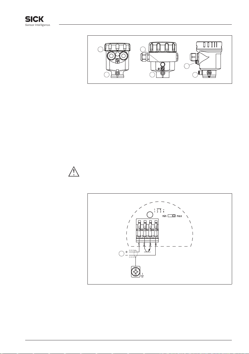
Gehäuseübersicht
5 An die Spannungsversorgung anschließen
Abb. 8: Werkstoffvarianten Einkammergehäuse
1 Kunststoff (nicht bei EEx d)
2 Aluminium
3 Edelstahl, elektropoliert
4 Filterelement für Luftdruckausgleich
Anschlussplan
Wir empfehlen den LBV 331 so anzuschließen, dass der Schaltstromkreis bei Grenzstandmeldung, Leitungsbruch oder Störung
geöffnet ist (sicherer Zustand).
Zum Ansteuern von Relais, Schützen, Magnetventilen, Leuchtmeldern, Hupen sowie von SPS-Eingängen.
Vorsicht:
Es besteht kein Verpolungsschutz. Beachten Sie die Polarität der
Ausgangsleitungen.
Abb. 9: Anschlussplan
39165-DE-110617
LBV 331 • - Transistor (NPN/PNP) 17
Page 18

+ -
+-
+-
+ -
1
2
3
4
5
5 An die Spannungsversorgung anschließen
Abb. 10: NPN-Verhalten
Abb. 11: PNP-Verhalten
5.4 Anschlussplan - Ausführung IP 66/IP 68, 1 bar
Aderbelegung An-
schlusskabel
Abb. 12: Aderbelegung Anschlusskabel. Die Nummern der Adern entsprechen
den Anschlussklemmen des Gerätes.
1 Braun (+) Spannungsversorgung
2 Weiß
3 Gelb
4 Blau (-) Spannungsversorgung
18 LBV 331 • - Transistor (NPN/PNP)
5 Abschirmung
39165-DE-110617
Page 19
3
4
5
1
2
6 In Betrieb nehmen
6 In Betrieb nehmen
6.1 Allgemein
Die Zahlenangaben in Klammern beziehen sich auf die nachfolgenden
Abbildungen.
Funktion/Aufbau
Elektronik- und An-
schlussraum
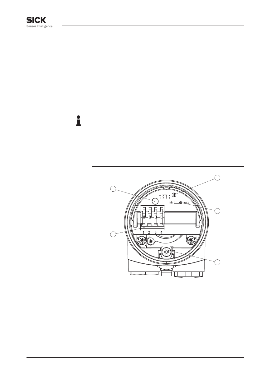
Auf dem Elektronikeinsatz finden Sie folgende Anzeige- und Bedienelemente:
l Potentiometer zur Anpassung an die Füllgutdichte (1)
l DIL-Schalter zur Betriebsartenumschaltung - min./max. (2)
l Kontrollleuchte (5)
Hinweis:
Stellen Sie generell vor der Inbetriebnahme des LBV 331 mit dem
Betriebsartenschalter (2) die Betriebsart ein. Wenn Sie den Betriebs-
artenschalter (2) nachträglich umschalten, ändert sich der Schaltausgang. Das heißt, nachgeschaltete Geräte we rden evtl. betätigt.
6.2 Bedienelemente
Abb. 13: Elektronik- und Anschlussraum - Transistorausgang
1 Potentiometer zur Schaltpunktanpassung
2 DIL-Schalter zur Betriebsartenumschaltung
3 Erdungsklemme
4 Anschlussklemmen
5 Kontrollleuchte
39165-DE-110617
LBV 331 • - Transistor (NPN/PNP) 19
Page 20

6 In Betrieb nehmen
Schaltpunktanpassung
(1)
Betriebsartenumschaltung (2)
Kontrollleuchte (5)
Mit dem Potentiometer können Sie den Schaltpunkt an das Schüttgut
anpassen. Es ist ab Werk voreingestellt und muss nur in Grenzfällen
verändert werden.
Das Potentiometer des LBV 331 steht ab Werk auf Rechtsanschlag
(> 0,3 g/cm³ bzw. 0.011 lbs/in³). Bei besonders leichten Schüttgütern
drehen Sie das Potentiometer auf Linksanschlag (0,02 … 0,1 g/cm³
bzw. 0.0007 … 0.0036 lbs/in³). Damit wird der LBV 331 empfindlicher
und kann leichte Schüttgüter sicherer detektieren.
Bei Geräten zur Feststoffdetektion in Wasser gelten diese Einstellungen nicht. Die Schaltpunktanpassung ist ab Werk eingestellt
und darf nicht verändert werden.
Mit der Betriebsartenumschaltung (min./max.) können Sie den
Schaltzustand des Transistorausgangs ändern. Sie können damit die
gewünschte Betriebsart gemäß "Funktionstabelle" einstellen (max. Maximalstanderfassung bzw. Überlaufschutz, min. - Minimalstander-
fassung bzw. Trockenlaufschutz).
Wir empfehlen, den Anschluss im Ruhestromprinzip (Schaltausgang
bei Erreichen des Schaltpunktes geöffnet), da der Transistorausgang
bei erkannter Störung den gleichen (sicheren) Zustand annimmt.
Kontrollleuchte zur Anzeige des Schaltzustandes
l Grün = Ausgang geschlossen
l Rot = Ausgang offen
l Rot (blinkt) = Störung
6.3 Funktionstabelle
Die folgende Tabelle gibt eine Übersicht über die Schaltzustände in
Abhängigkeit von der eingestellten Betriebsart und dem Füllstand.
Füllstand Schaltzustand Kontrollleuchte
Betriebsart max.
Überlaufschutz
Betriebsart max.
Überlaufschutz
Betriebsart min.
Trockenlaufschutz
geschlossen
Grün
offen
Rot
geschlossen
Grün
20 LBV 331 • - Transistor (NPN/PNP)
39165-DE-110617
Page 21

Füllstand Schaltzustand Kontrollleuchte
Betriebsart min.
Trockenlaufschutz
Ausfall der Span-
nungsversorgung
(Betriebsart min./
max.)
Störung beliebig offen
beliebig offen
offen
6 In Betrieb nehmen
Rot
blinkt rot
39165-DE-110617
LBV 331 • - Transistor (NPN/PNP) 21
Page 22

7 Instandhalten und Störungen beseitigen
7 Instandhalten und Störungen beseitigen
7.1 Wartung
Bei bestimmungsgemäßer Verwendung ist im Normalbetrieb keine
besondere Wartung erforderlich.
7.2 Störungen beseitigen
Verhalten bei Störungen
Störungsursachen
Störungsbeseitigung
Schaltsignal überprüfen
Es liegt in der Verantwortung des Anlagenbetreibers, geeignete
Maßnahmen zur Beseitigung aufgetretener Störungen zu ergreifen.
Der LBV 331 bietet Ihnen ein Höchstmaß an Funktionssicherheit.
Dennoch können während des Betriebes Störungen auftreten. Diese
können z. B. folgende Ursachen haben:
l Sensor
l Prozess
l Spannungsversorgung
l Signalauswertung
Die erste Maßnahme ist die Überprüfung des Ausgangssignals. In
vielen Fällen lassen sich die Ursachen auf diesem Wege feststellen
und die Störungen so beseitigen.
Fehler Ursache Beseitigung
Der LBV 331
meldet bedeckt
ohne Füllgutbedeckung (Überfüllsicherung)
Der LBV 331
meldet unbedeckt
mit Füllgutbedeckung (Trockenlaufschutz)
Betriebsspannung zu niedrig
Elektronik defekt Betriebsartenschalter betätigen.
Einbauort un-
günstig
Anhaftungen am
Schwingelement
Betriebsspannung prüfen
Wenn das Gerät daraufhin umschaltet,
kann das Schwingelement mit Anhaftungen bedeckt oder mechanisch beschädigt sein. Sollte die Schaltfunktion
auf der korrekten Betriebsart wieder
fehlerhaft sein, senden Sie das Gerät
zur Reparatur ein.
Betriebsartenschalter betätigen.
Wenn das Gerät daraufhin nicht um-
schaltet, ist der Elektronikeinsatz defekt. Elektronikeinsatz tauschen.
Gerät an einer Stelle einbauen, an der
sich keine Toträume oder Wächten im
Behälter bilden können.
Kontrollieren Sie das Schwingelement
und den Stutzen auf eventuelle Anhaftungen und entfernen Sie diese.
39165-DE-110617
22 LBV 331 • - Transistor (NPN/PNP)
Page 23

7 Instandhalten und Störungen beseitigen
Fehler Ursache Beseitigung
Kontrollleuchte
blinkt rot
Falsche Betriebsart gewählt
Fehler am
Schwingelement
Störung an der
Elektronik
Gerät defekt Gerät austauschen bzw. zur Repara-
Korrekte Betriebsart am Betriebsar-
tenschalter einstellen (Überlaufschutz,
Trockenlaufschutz). Die Verkabelung
sollte nach dem Ruhestromprinzip
ausgeführt werden.
Kontrollieren Sie, ob das Schwingelement beschädigt oder stark korrodiert ist.
Elektronikeinsatz tauschen
tur einsenden
Verhalten nach Stö-
rungsbeseitigung
Je nach Störungsursache und getroffenen Maßnahmen sind ggf. die
im Kapitel "In Betrieb nehmen" beschriebenen Handlungsschritte
erneut zu durchlaufen.
7.3 Elektronikeinsatz tauschen
Generell können alle Elektronikeinsätze der Typenreihe VB60 unter-
einander getauscht werden. Falls Sie einen Elektronikeinsatz mit
einem anderen Signalausgang verwenden wollen, können Sie die
dazu passende Betriebsanleitung auf unserer Homepage unter
Downloads herunterladen.
Bei EEx-d-Geräten darf der Gehäusedeckel nur dann geöffnet werden,
wenn keine explosionsfähige Atmosphäre vorhanden ist.
Gehen Sie wie folgt vor:
1 Spannungsversorgung abschalten
2 Gehäusedeckel abschrauben
3 Öffnungshebel der Klemmen mit einem Schraubendreher an-
heben
4 Anschlussleitungen aus den Klemmen herausziehen
5 Die beiden Halteschrauben mit einem Schraubendreher (Torx
Größe T10 oder Schlitz 4) lösen
39165-DE-110617
LBV 331 • - Transistor (NPN/PNP) 23
Page 24

2
1
7 Instandhalten und Störungen beseitigen
Abb. 24: Halteschrauben lösen
1 Elektronikeinsatz
2 Halteschrauben (2 Stück)
6 Den alten Elektronikeinsatz herausziehen
7 Neuen Elektronikeinsatz mit dem Alten vergleichen. Das Typschild
auf dem Elektronikeinsatz muss dem Typschild des alten
Elektronikeinsatzes entsprechen. Dies gilt vor allem für Geräte in
explosionsgeschützten Bereichen.
8 Einstellungen der beiden Elektronikeinsätze vergleichen. Die
Bedienelemente des neuen Elektronikeinsatzes auf dieselbe
Einstellung des alten Elektronikeinsatzes stellen.
Information:
Achten Sie darauf, dass das Gehäuse während des Elektroniktausches nicht verdreht wird. Der Stecker kann dadurch in einer anderen
Stellung stehen.
9 Elektronikeinsatz vorsichtig einstecken. Darauf achten, dass der
Stecker in korrekter Position steht.
10 Die beiden Halteschrauben mit einem Schraubendreher (Torx
Größe T10 oder Schlitz 4) einschrauben und festziehen
11 Aderenden nach Anschlussplan in die offenen Klemmen stecken
12 Öffnungshebel der Klemmen nach unten drücken, die Klemmen-
feder schließt hörbar
13 Korrekten Sitz der Leitungen in den Klemmen durch leichtes
Ziehen prüfen
14 Kabelverschraubung auf Dichtigkeit überprüfen. Der Dichtring
muss das Kabel komplett umschließen.
15 Gehäusedeckel verschrauben
Der Elektroniktausch ist somit abgeschlossen.
39165-DE-110617
7.4 Das Gerät reparieren
Sollte eine Reparatur erforderlich sein, wenden Sie sich bitte an die
zuständige Sick-Vertretung.
24 LBV 331 • - Transistor (NPN/PNP)
Page 25

8 Ausbauen
8 Ausbauen
8.1 Ausbauschritte
Warnung:
Achten Sie vor dem Ausbauen auf gefährliche Prozessbedingungen
wie z. B. Druck im Behälter, hohe Temperaturen, aggressive oder
toxische Füllgüter etc.
Beachten Sie die Kapitel "Montage" und "An die Spannungsversor-
gung anschließen" und führen Sie die dort angegebenen Schritte
sinngemäß umgekehrt durch.
Bei Ex-Geräten darf der Gehäusedeckel nur dann geöffnet werden,
wenn keine explosionsfähige Atmosphäre vorhanden ist.
8.2 Entsorgen
Das Gerät besteht aus Werkstoffen, die von darauf spezialisierten
Recyclingbetrieben wieder verwertet werden können. Wir haben
hierzu die Elektronik leicht trennbar gestaltet und verwenden
recyclebare Werkstoffe.
WEEE-Richtlinie 2002/96/EG
Das vorliegende Gerät unterliegt nicht der WEEE-Richtlinie 2002/96/
EG und den entsprechenden nationalen G esetzen. Führen Sie das
Gerät direkt einem spezialisierten Recyclingbetrieb zu und nutzen Sie
dafür nicht die kommunalen Sammelstellen. Diese dürfen nur für privat
genutzte Produkte gemäß WEEE-Richtlinie genutzt werden.
Eine fachgerechte Entsorgung vermeidet negative Auswirkungen auf
Mensch und Umwelt und ermöglicht eine Wiederverwendung von
wertvollen Rohstoffen.
Werkstoffe: siehe Kapitel "Technische Daten"
Sollten Sie keine Möglichkeit haben, das Altgerät fachgerecht zu
entsorgen, so sprechen Sie mit uns über Rücknahme und Entsorgung.
39165-DE-110617
LBV 331 • - Transistor (NPN/PNP) 25
Page 26

9 Anhang
9 Anhang
9.1 Technische Daten
Allgemeine Daten
Werkstoff 316L entspricht 1.4404 oder 1.4435
Werkstoffe, medienberührt
- Prozessanschluss - Gewinde 316L
- Prozessanschluss - Flansch 316L
- Prozessdichtung Klingersil C-4400
- Schwingstab 316L, 318 S13 (1.4462)
- Verlängerungsrohr ø 29 mm (1.14 in) 316L
Werkstoffe, nicht medienberührt
- Kunststoffgehäuse Kunststoff PBT (Polyester)
- Aluminium-Druckgussgehäuse Aluminium-Druckguss AlSi10Mg, pulverbeschichtet
- Edelstahlgehäuse, elektropoliert 316L
- Dichtung zwischen Gehäuse und Ge-
häusedeckel
- Lichtleiter im Gehäusedeckel (Kunst-
stoff)
- Erdungsklemme 316L
Prozessanschlüsse
- Rohrgewinde, zylindrisch (DIN 3852-A) G1 A, G1½ A
- Amerikan. Rohrgewinde, kegelig
(ASME B1.20.1)
Gewicht ca.
- Gerätegewicht (je nach Prozessan-
schluss)
- Verlängerungsrohr 1450 g/m (15.6 oz/ft)
Sensorlänge (L) 0,3 … 6 m (0.984 … 19.69 ft)
Max. seitliche Belastung 140 Nm, max. 400 N (103 lbf ft, max. 90 lbf)
- Basis: Polyester
Silikon
PMMA (Makrolon)
1 NPT, 1½ NPT
0,8 … 4 kg (0.18 … 8.82 lbs)
Ausgangsgröße
Ausgang Potenzialfreier Transistorausgang, dauerkurz-
schlussfest
Laststrom < 400 mA
Schaltspannung < 55 V DC
Sperrstrom < 100 µA
Betriebsarten (umschaltbar) min./max.
Schaltverzögerung
- Bei Bedeckung 0,5 s
26 LBV 331 • - Transistor (NPN/PNP)
39165-DE-110617
Page 27

6 bar
(87psi)
-50°C
(-58°F)
16 bar
(232psi)
50°C
(122°F)
100°C
(212°F)
0°C
(32°F)
150°C
(302°F)
200°C
(392°F)
250°C
(482°F)
1
2
1
2
3
-50°C
(-58°F)
50°C
(122°F)
40°C
(104°F)
-40°C
(-40°F)
80°C
(176°F)
0°C
(32°F)
100°C
(212°F)
150°C
(302°F)
200°C
(392°F)
250°C
(482°F)
9 Anhang
- Bei Freiwerden 1 s
Umgebungsbedingungen
Umgebungstemperatur am Gehäuse -40 … +80 °C (-40 … +176 °F)
Lager- und Transporttemperatur -40 … +80 °C (-40 … +176 °F)
Prozessbedingungen
Messgröße Grenzstand von Schüttgütern
Prozessdruck -1 … 16 bar/-100 … 1600 kPa (-14.5 … 232 psig)
Abb. 25: Prozessdruck - Prozesstemperatur
1 Prozesstemperatur
2 Prozessdruck
LBV 331 aus 316L -50 … +150 °C (-58 … +302 °F)
Prozesstemperatur (Gewinde- bzw.
-50 … +250 °C (-58 … +482 °F)
Flanschtemperatur) mit Temperaturzwi-
schenstück (optional)
Abb. 26: Umgebungstemperatur - Prozesstemperatur
1 Prozesstemperatur
2 Umgebungstemperatur
3 Temperaturbereich mit Temperaturzwischenstück
39165-DE-110617
LBV 331 • - Transistor (NPN/PNP) 27
Page 28

9 Anhang
Dichte
- Standard > 0,05 g/cm³ (0.002 lbs/in³)
- Einstellbar > 0,02 g/cm³ (0.0007 lbs/in³)
Korngröße keine Einschränkung
1)
Elektromechanische Daten - Ausführung IP 66/IP 67 und IP 66/IP 68; 0,2 bar
Kabeleinführung/Stecker
2)
- Einkammergehäuse l 1 x Kabelverschraubung M20 x 1,5 (Kabel:
ø 5 … 9 mm), 1 x Blindstopfen M20 x 1,5
oder:
l 1 x Verschlusskappe ½ NPT, 1 x Blindstopfen
½ NPT
oder:
l 1 x Stecker (je nach Ausführung), 1 x Blind-
stopfen M20 x 1,5
Federkraftklemmen für Leitungsquerschnitt bis 1,5 mm² (AWG 16)
Elektromechanische Daten - Ausführung IP 66/IP 68 (1 bar)
Kabeleinführung
- Einkammergehäuse l 1 x IP 68-Kabelverschraubung M20 x 1,5; 1 x
Blindstopfen M20 x 1,5
oder:
l 1 x Verschlusskappe ½ NPT, 1 x Blindstopfen
½ NPT
Anschlusskabel
- Aufbau vier Adern, ein Tragseil, eine Druckausgleichska-
pillare, Schirmgeflecht, Folie, Mantel
- Leitungsquerschnitt 0,5 mm²
- Aderwiderstand < 0,036 Ω/m (0.011 Ω/ft)
- Zugfestigkeit > 1200 N (270 pounds force)
- Standardlänge 5 m (16.4 ft)
- Max. Länge 1000 m (3280 ft)
- Min. Biegeradius 25 mm (bei 25 °C/77 °F)
- Durchmesser ca. 8 mm
- Farbe - Standard PE Schwarz
- Farbe - Standard PUR Blau
- Farbe - Ex-Ausführung Blau
Bedienelemente
Betriebsartenschalter
1)
max. 20 mm (0.8 in) bei Füllgutdichte < 0,05 g/cm³ (0.002 lbs/in³).
2)
Je nach Ausführung M12 x 1, nach ISO 4400, Harting, 7/8" FF.
28 LBV 331 • - Transistor (NPN/PNP)
39165-DE-110617
Page 29

9 Anhang
- Min. Minimalstanderfassung bzw. Trockenlaufschutz
- Max. Maximalstanderfassung bzw. Überlaufschutz
Spannungsversorgung
Betriebsspannung 10 … 55 V DC
Leistungsaufnahme max. 0,5 W
Elektrische Schutzmaßnahmen
Schutzart
- Kunststoffgehäuse IP 66/IP 67
- Aluminium- und Edelstahlgehäuse Stan-
IP 66/IP 68 (0,2 bar)
3)
dard
- Aluminium- und Edelstahlgehäuse (op-
IP 66/IP 68 (1 bar)
tional)
Überspannungskategorie III
Schutzklasse II
Zulassungen
Geräte mit Zulassungen können je nach Ausführung abweichende technische Daten haben. Bei
diesen Geräten sind deshalb die zugehörigen Zulassungsdokumente zu beachten. Diese sind im
Gerätelieferumfang enthalten.
3)
Voraussetzung für die Einhaltung der Schutzart ist das passende Kabel.
39165-DE-110617
LBV 331 • - Transistor (NPN/PNP) 29
Page 30

~ 69 mm
(2.72")
ø 79 mm
(3.11")
110 mm (4.33")
M20x1,5/
½ NPT
~ 116 mm (4.57")
ø 86 mm (3.39")
108 mm (4.25")
M20x1,5M20x1,5/
½ NPT
1 2
~ 59 mm
(2.32")
ø 80 mm
(3.15")
112 mm (4.41")
M20x1,5/
½ NPT
3
9 Anhang
9.2 Maße
LBV 331
Abb. 27: Gehäuseausführungen
1 Kunststoffgehäuse
2 Aluminiumgehäuse
3 Edelstahlgehäuse, elektropoliert
30 LBV 331 • - Transistor (NPN/PNP)
39165-DE-110617
Page 31

20mm
(
25
/
32
")
25mm
(
63
/
64
")
L
125mm (4
59
/
64
")
ø16mm (5/8")
G1A
ø 29mm (1 9/64")
9 Anhang
Abb. 28: LBV 331 - Gewindeausführung G1 A (DIN ISO 228/1)
L Sensorlänge, siehe Kapitel "Technische Daten"
39165-DE-110617
LBV 331 • - Transistor (NPN/PNP) 31
Page 32

22mm
(
55
/
64
")
33mm
(1
19
/
64
")
L
125mm (4
59
/
64
")
ø16mm (5/8")
G1½A
ø 29mm (1 9/64")
9 Anhang
Abb. 29: LBV 331 - Gewindeausführung G1½ A (DIN ISO 228/1)
32 LBV 331 • - Transistor (NPN/PNP)
L Sensorlänge, siehe Kapitel "Technische Daten"
39165-DE-110617
Page 33

ø 34 mm
(1.34")
178 mm (7.01")
9 Anhang
Abb. 30: Temperaturzwischenstück
39165-DE-110617
LBV 331 • - Transistor (NPN/PNP) 33
Page 34

9 Anhang
34 LBV 331 • - Transistor (NPN/PNP)
39165-DE-110617
Page 35

9 Anhang
39165-DE-110617
LBV 331 • - Transistor (NPN/PNP) 35
Page 36

8013986/20111706 · VS · Printed in Germany (201106) · Änderungen vorbehalten
Angegebene Produkteigenschaften und technische Daten stellen keine Garantieerklärung dar
LBV 331
39165-DE-110617
Page 37

GB
LB V 331
- t r an s ist or (N P N/ P N P)
O P E R A T I N G I N S T R U C T I O N S
Page 38

Contents
Contents
1 About this document
1.1 Function. . . . . . . . . . . . . . . . . . . . . . . . . . . . . . . . . .
1.2 Target group . . . . . . . . . . . . . . . . . . . . . . . . . . . . . .
1.3 Symbolism used. . . . . . . . . . . . . . . . . . . . . . . . . . . .
2 For your safety
2.1 Authorised personnel . . . . . . . . . . . . . . . . . . . . . . . .
2.2 Appropriate use . . . . . . . . . . . . . . . . . . . . . . . . . . . .
2.3 Warning about misuse . . . . . . . . . . . . . . . . . . . . . . .
2.4 General safety instructions . . . . . . . . . . . . . . . . . . . .
2.5 Safety label on the instrument . . . . . . . . . . . . . . . . . .
2.6 CE conformity . . . . . . . . . . . . . . . . . . . . . . . . . . . . .
2.7 Safety instructions for Ex areas . . . . . . . . . . . . . . . . .
3 Product description
3.1 Structure . . . . . . . . . . . . . . . . . . . . . . . . . . . . . . . . .
3.2 Principle of operation . . . . . . . . . . . . . . . . . . . . . . . .
3.3 Configuration . . . . . . . . . . . . . . . . . . . . . . . . . . . . . .
3.4 Storage and transport . . . . . . . . . . . . . . . . . . . . . . .
4 Mounting
4.1 General instructions . . . . . . . . . . . . . . . . . . . . . . . . .
4.2 Mounting instructions . . . . . . . . . . . . . . . . . . . . . . . .
5 Connecting to power supply
5.1 Preparing the connection . . . . . . . . . . . . . . . . . . . . .
5.2 Connection procedure. . . . . . . . . . . . . . . . . . . . . . . .
5.3 Wiring plan, single chamber housing . . . . . . . . . . . . .
5.4 Wiring plan - version IP 66/IP 68, 1 bar . . . . . . . . . . .
4
4
4
5
5
5
5
6
6
6
7
8
8
9
10
11
15
15
16
18
6 Set up
6.1 General information . . . . . . . . . . . . . . . . . . . . . . . . .
6.2 Adjustment elements . . . . . . . . . . . . . . . . . . . . . . . .
6.3 Function chart . . . . . . . . . . . . . . . . . . . . . . . . . . . . .
7 Maintenance and fault rectification
7.1 Maintenance . . . . . . . . . . . . . . . . . . . . . . . . . . . . . .
7.2 Fault rectification . . . . . . . . . . . . . . . . . . . . . . . . . . .
7.3 Exchanging the electronics module . . . . . . . . . . . . . .
7.4 Instrument repair . . . . . . . . . . . . . . . . . . . . . . . . . . .
8 Dismounting
8.1 Dismounting steps . . . . . . . . . . . . . . . . . . . . . . . . . .
8.2 Disposal . . . . . . . . . . . . . . . . . . . . . . . . . . . . . . . . .
9 Supplement
9.1 Technical data . . . . . . . . . . . . . . . . . . . . . . . . . . . . .
9.2 Dimensions . . . . . . . . . . . . . . . . . . . . . . . . . . . . . . .
2 LBV 331 • - transistor (NPN/PNP)
19
19
20
22
22
23
24
25
25
26
30
39165-EN-110621
Page 39

Contents
Safety instructions for Ex areas
Please note the Ex-specific safety information for installation and
operation in Ex areas. These safety instructions are part of the
operating instructions manual and come with the Ex-approved
instruments.
Editing status: 2011-06-17
39165-EN-110621
LBV 331 • - transistor (NPN/PNP) 3
Page 40

1 About this document
1 About this document
1.1 Function
This operating instructions manual provides all the information you
need for mounting, connection and setup as well as important
instructions for maintenance and fault rectification. Please read this
information before putting the instrument into operation and keep this
manual accessible in the immediate vicinity of the device.
1.2 Target group
This operating instructions manual is directed to trained qualified
personnel. The contents of this manual should be made available to
these personnel and put into practice by them.
1.3 Symbolism used
Information, tip, note
This symbol indicates helpful additional information.
Caution: If this warning is ignored, faults or malfunctions can
result.
Warning: If this warning is ignored, injury to persons and/or serious
damage to the instrument can result.
Danger: If this warning is ignored, serious injury to persons and/or
destruction of the instrument can result.
Ex applications
This symbol indicates special instructions for Ex applications.
l List
The dot set in front indicates a list with no implied sequence.
à Action
This arrow indicates a single action.
1 Sequence
Numbers set in front indicate successive steps in a procedure.
4 LBV 331 • - transistor (NPN/PNP)
39165-EN-110621
Page 41

2 For your safety
2 For your safety
2.1 Authorised personnel
All operations described in this operating instructions manual must be
carried out only by trained specialist personnel authorised by the plant
operator.
During work on and with the device the required personal protective
equipment must always be worn.
2.2 Appropriate use
The LBV 331 is a sensor for level detection.
You can find detailed information on the application range in chapter
"Product description".
Operational reliability is ensured only if the instrument is properly used
according to the specifications in the operating instructions manual as
well as possible supplementary instructions.
For safety and warranty reasons, any invasive work on the device
beyond that described in the operating instructions manual may be
carried out only by personnel authorised by the manufacturer. Arbitrary
conversions or modifications are explicitly forbidden.
2.3 Warning about misuse
Inappropriate or incorrect use of the instrument can give rise to
application-specific hazards, e.g. vessel overfill or damage to system
components through incorrect mounting or adjustment.
2.4 General safety instructions
This is a high-tech instrument requiring the strict observance of
standard regulations and guidelines. The user must take note of the
safety instructions in this operating instructions manual, the countryspecific installation standards as well as all prevailing safety
regulations and accident prevention rules.
The instrument must only be operated in a technically flawless and
reliable condition. The operator is responsible for trouble-free
operation of the instrument.
During the entire duration of use, the user is obliged to determine the
compliance of the necessary occupational safety measures with the
current valid rules and regulations and also take note of new
regulations.
39165-EN-110621
LBV 331 • - transistor (NPN/PNP) 5
Page 42

2 For your safety
2.5 Safety label on the instrument
The safety approval markings and safety tips on the device must be
observed.
2.6 CE conformity
This device fulfills the legal requirements of the applicable EC
guidelines. By attaching the CE mark, we provide confirmation of
successful testing.
2.7 Safety instructions for Ex areas
Please note the Ex-specific safety information for installation and
operation in Ex areas. These safety instructions are part of the
operating instructions manual and come with the Ex-approved
instruments.
6 LBV 331 • - transistor (NPN/PNP)
39165-EN-110621
Page 43

3 Product description
1
2
3
3.1 Structure
3 Product description
Scope of delivery
Constituent parts
The scope of delivery encompasses:
l LBV 331 point level switch
l Documentation
- this operating instructions manual
- Ex-specific "Safety instructions" (with Ex versions)
- if necessary, further certificates
The LBV 331 consists of the components:
l Housing cover
l Housing with electronics
l Process fitting with vibrating rod
Fig. 1: LBV 331 - with plastic housing
1 Housing cover
2 Housing with electronics
3 Process fitting
Type label
The type label contains the most important data for identification and
use of the instrument:
l Article number
l Serial number
l Technical data
l Article numbers, documentation
In addition to the type label outside on the instrument, you find the
serial number also inside the instrument.
39165-EN-110621
LBV 331 • - transistor (NPN/PNP) 7
Page 44

3 Product description
3.2 Principle of operation
Application area
Functional principle
LBV 331 is a point level sensor with vibrating rod for level detection.
It is designed for industrial use in all areas of process technology and
is preferably used for bulk solids.
Typical applications are overfill and dry run protection. Thanks to its
simple and robust measuring system, LBV 331 is virtually unaffected
by the chemical and physical properties of the bulk solid.
It also works when subjected to strong external vibrations or changing
products.
Solid detection in water
If LBV 331 was ordered for solid detection in water, the vibrating rod is
calibrated to the density of water. If covered by water (density: 1 g/cm³/
0.036 lbs/in) LBV 331 signals "uncovered". Only if the vibrating
element is also covered with solids (e.g. sand, sludge, gravel etc.) will
the sensor signal "covered".
Fault monitoring
The electronics module of LBV 331 monitors continuously the
following criteria:
l Correct vibrating frequency
l Line break to the piezo drive
If a malfunction is detected or in case of power failure, the electronics
takes on a defined switching condition, i.e. the output is open (safe
condition).
The vibrating rod is piezoelectrically energised and vibrates at its
mechanical resonance frequency of approx. 360 Hz. When the
vibrating rod is submerged in the product, the vibration amplitude
changes. This change is detected by the integrated electronics module
and converted into a switching command.
Voltage supply
LBV 331 is a compact instrument, i.e. it can be operated without
external evaluation system. The integrated electronics evaluates the
level signal and outputs a switching signal. With this switching signal, a
connected device can be operated directly (e.g. a warning system, a
PLC, a pump etc.).
The data for power supply are specified in chapter "Technical data".
3.3 Configuration
With the factory setting, products with a density of > 0.05 g/cm³
(0.002 lbs/in³) can be measured. It is possible to adapt the instrument
for products with lower density > 0.02 g/cm³ (0.0007 lbs/in³).
On the electronics module you will find the following indicating and
adjustment elements:
l Signal lamp for indication of the switching condition (green/red)
8 LBV 331 • - transistor (NPN/PNP)
39165-EN-110621
Page 45

3 Product description
l Potentiometer for adaptation to the product density
l Mode switch for selecting the switching condition (min./max.)
3.4 Storage and transport
Packaging
Transport
Transport inspection
Storage
Storage and transport
temperature
The device was protected by packaging during transport. Its capacity
to handle normal loads during transport is assured by a test according
to DIN EN 24180.
The packaging of standard instruments consists of environmentfriendly, recyclable cardboard. In addition, the sensor is provided with
a protective cover of paperboard. For special versions PE foam or PE
foil is also used. Dispose of the packaging material via specialised
recycling companies.
Transport must be carried out under consideration of the notes on the
transport packaging. Nonobservance of these instructions can cause
damage to the device.
The delivery must be checked for completeness and possible transit
damage immediately at receipt. Ascertained transit damage or
concealed defects must be appropriately dealt with.
Up to the time of installation, the packages must be left closed and
stored according to the orientation and storage markings on the
outside.
Unless otherwise indicated, the packages must be stored only under
the following conditions:
l Not in the open
l Dry and dust free
l Not exposed to corrosive media
l Protected against solar radiation
l Avoiding mechanical shock and vibration
l Storage and transport temperature see chapter "Supplement -
Technical data - Ambient conditions"
l Relative humidity 20 … 85 %
39165-EN-110621
LBV 331 • - transistor (NPN/PNP) 9
Page 46

4 Mounting
4 Mounting
4.1 General instructions
Suitability for the process conditions
Switching point
Moisture
Make sure that all parts of the instrument exposed to the process, in
particular the sensor element, process seal and process fitting, are
suitable for the existing process conditions. These include above all
the process pressure, process temperature as well as the chemical
properties of the medium.
You can find the specifications in chapter "Technical data" or on the
type label.
In general, LBV 331 can be installed in any position. The instrument
only has to be mounted in such a way that the vibrating element is at
the height of the desired switching point.
Use the recommended cables (see chapter "Connecting to power
supply") and tighten the cable gland.
You can give your instrument additional protection against moisture
penetration by leading the connection cable downward in front of the
cable entry. Rain and condensation water can thus drain off. This
applies mainly to outdoor mounting as well as installation in areas
where high humidity is expected (e.g. through cleaning processes) or
on cooled or heated vessels.
Fig. 2: Measures against moisture penetration
Transport
10 LBV 331 • - transistor (NPN/PNP)
Do not hold LBV 331 on the vibrating element. Especially with flange
and tube versions, the sensor can be damaged by the weight of the
instrument.
Remove the protective cover just before mounting.
39165-EN-110621
Page 47

4 Mounting
Pressure/Vacuum
Handling
Agitators and fluidiza-
tion
The process fitting must be sealed if there is gauge or low pressure in
the vessel. Before use, check if the seal material is resistant against
the measured product and the process temperature.
The max. permissible pressure is specified in chapter "Technical data"
or on the type label of the sensor.
The vibrating level switch is a measuring instrument and must be
treated accordingly. Bending the vibrating element will destroy the
instrument.
Warning:
The housing must not be used to screw the instrument in! Applying
tightening force can damage internal parts of the housing.
Use the hexagon above the thread for screwing in.
4.2 Mounting instructions
Due to the effects of agitators, equipment vibration or similar, the level
switch can be subjected to strong lateral forces. For this reason, do not
use an overly long extension tube for LBV 331, but check if you can
mount a short level switch on the side of the vessel in horizontal
position.
Extreme vibration caused by the process or the equipment, e.g.
agitators or turbulence in the vessel e.g. from fluidization, can cause
the extension tube of LBV 331 to vibrate in resonance. This leads to
increased stress on the upper weld joint. Should a longer tube version
be necessary, you can provide a suitable support directly above the
tuning fork to secure the extension tube.
This measure applies mainly to applications in Ex areas. Make sure that
the tube is not subject to bending stress due to this measure.
Inflowing medium
39165-EN-110621
LBV 331 • - transistor (NPN/PNP) 11
If LBV 331 is mounted in the filling stream, unwanted false measure-
ment signals can be generated. For this reason, mount LBV 331 at a
position in the vessel where no disturbances, e.g. from filling openings,
agitators, etc., can occur.
This applies particularly to instrument types with long extension tube.
Page 48

4 Mounting
Fig. 3: Inflowing medium
Lock fitting
Socket
Material cone
LBV 331 can be mounted with a lock fitting for height adjustment. Take
note of the pressure information of the lock fitting.
The vibrating element should protrude into the vessel to avoid buildup.
For that reason, avoid using mounting bosses for flanges and screwed
fittings. This applies particularly to use with adhesive products.
In silos for bulk solids, material cones can form and change the
switching point. Please keep this in mind when installing the sensor in
the vessel. We recommend selecting an installation location where the
vibrating rod detects an average value of the material cone.
The vibrating rod must be mounted in a way that takes the
arrangement of the filling and emptying apertures into account.
To compensate measurement errors caused by the material cone in
cylindrical vessels, the sensor must be mounted at a distance of d/6
from the vessel wall.
39165-EN-110621
12 LBV 331 • - transistor (NPN/PNP)
Page 49

d d
d
6
d
6
Fig. 4: Filling and emptying centred
d
d
6
1
2
3
4 Mounting
Fig. 5: Filling in the centre, emptying laterally
1 LBV 331
2 Discharge opening
3 Filling opening
39165-EN-110621
LBV 331 • - transistor (NPN/PNP) 13
Page 50

> 125 mm
(4 59/64")
4 Mounting
Baffle protection against
falling rocks
In applications such as grit chambers or settling basins for coarse
sediments, the vibrating element must be protected against damage
with a suitable baffle.
This baffle must be manufactured by you.
Fig. 6: Baffle for protection against mechanical damage
14 LBV 331 • - transistor (NPN/PNP)
39165-EN-110621
Page 51

5 Connecting to power supply
5 Connecting to power supply
5.1 Preparing the connection
Note safety instructions
Take note of
safety instructions for Ex applications
Voltage supply
Connection cable
Connection ca-
ble for Ex applications
Always keep in mind the following safety instructions:
l Connect only in the complete absence of line voltage
In hazardous areas you must take note of the respective regulations,
conformity and type approval certificates of the sensors and power
supply units.
Connect the operating voltage according to the following diagrams.
Take note of the general installation regulations. As a rule, connect
LBV 331 to vessel ground (PA), or in case of plastic vessels, to the
next ground potential. On the side of the instrument housing there is a
ground terminal between the cable entries. This connection serves to
drain off electrostatic charges. In Ex applications, the installation
regulations for hazardous areas must be given priority.
The data for power supply are specified in chapter "Technical data".
The instrument is connected with standard two-wire cable without
screen. If electromagnetic interference is expected which is above the
test values of EN 61326 for industrial areas, screened cable should be
used.
Use cable with round cross-section. A cable outer diameter of 5 … 9 mm
(0.2 … 0.35 in) ensures the seal effect of the cable gland. If you are
using cable with a different diameter or cross-section, exchange the
seal or use a suitable cable gland.
In hazardous areas, only use approved cable connections for LBV 331.
Take note of the corresponding installation regulations for Ex
applications.
5.2 Connection procedure
With Ex instruments, the housing cover may only be opened if there is
no explosive atmosphere present.
Proceed as follows:
1 Unscrew the housing cover
2 Loosen compression nut of the cable entry
3 Remove approx. 10 cm (4 in) of the cable mantle, strip approx.
1 cm (0.4 in) of insulation from the ends of the individual wires
4 Insert the cable into the sensor through the cable entry
5 Lift the opening levers of the terminals with a screwdriver (see
following illustration)
39165-EN-110621
LBV 331 • - transistor (NPN/PNP) 15
Page 52

5 Connecting to power supply
Fig. 7: Connection steps 5 and 6
6 Insert the wire ends into the open terminals according to the wiring
plan
7 Press down the opening levers of the terminals, you will hear the
terminal spring closing
8 Check the hold of the wires in the terminals by lightly pulling on
them
9 Tighten the compression nut of the cable entry. The seal ring must
completely encircle the cable
10 If necessary, carry out a fresh adjustment
11 Screw the housing cover on
The electrical connection is finished.
5.3 Wiring plan, single chamber housing
The following illustrations apply to the non-Ex as well as to the EEx-d
version.
16 LBV 331 • - transistor (NPN/PNP)
39165-EN-110621
Page 53
1 2
4 4
4
3
1
Housing overview
5 Connecting to power supply
Fig. 8: Material versions, single chamber housing
1 Plastic (not with EEx d)
2 Aluminium
3 Stainless steel, electro-polished
4 Filter element for air pressure compensation
Wiring plan
We recommend connecting LBV 331 in such a way that the switching
circuit is open when there is a level signal, line break or failure (safe
condition).
The instrument is used to control relays, contactors, magnet valves,
warning lights, horns as well as PLC inputs.
Caution:
There is no reverse polarity protection. Take note of the polarity of the
output lines.
Fig. 9: Wiring plan
39165-EN-110621
LBV 331 • - transistor (NPN/PNP) 17
Page 54

+ -
+-
+-
+ -
1
2
3
4
5
5 Connecting to power supply
Fig. 10: NPN action
Fig. 11: PNP action
5.4 Wiring plan - version IP 66/IP 68, 1 bar
Wire assignment con-
nection cable
Fig. 12: Wire assignment connection cable. The numbers of the wires
correspond to the terminals of the instrument.
1 brown (+) voltage supply
2 White
3 Yellow
4 blue (-) voltage supply
5 Shielding
18 LBV 331 • - transistor (NPN/PNP)
39165-EN-110621
Page 55

6 Set up
3
4
5
1
2
6.1 General information
The figures in brackets refer to the following illustrations.
6 Set up
Function/Configuration
Electronics and connec-
tion compartment
On the electronics module you will find the following indicating and
adjustment elements:
l Potentiometer for adaptation to the product density (1)
l DIL switch for mode adjustment - min./max. (2)
l Signal lamp (5)
Note:
As a rule, always set the mode with mode switch (2) before starting the
setup of LBV 331. The switching output will change if you set the mode
switch (2) afterwards. This could possibly trigger other connected
instruments or devices.
6.2 Adjustment elements
Fig. 13: Electronics and connection compartment - transistor output
1 Potentiometer for switching point adaptation
2 DIL switch for mode adjustment
3 Ground terminal
4 Connection terminals
5 Control lamp
Switching point adaptation (1)
39165-EN-110621
LBV 331 • - transistor (NPN/PNP) 19
With the potentiometer you can adapt the switching point to the solid. It
is already preset and must only be modified in special cases.
Page 56

6 Set up
As a default setting, the potentiometer of LBV 331 is set to the
complete right position (> 0.3 g/cm³/0.011 lbs/in³). In very light solids
you have to turn the potentiometer to the complete left position
(0.02 … 0.1 g/cm³ or 0.0007 … 0.0036 lbs/in³). By doing this, LBV 331
will be more sensitive and light solids can be detected more reliably.
For instruments detecting solids in water, these settings are not
applicable. The switching point adaptation is preset and must not be
changed.
Mode adjustment (2)
Signal lamp (5)
With the mode adjustment (min./max.) you can change the switching
condition of the transistor output. You can set the required mode
according to the "Function chart" (max. - max. detection or overflow
protection, min. - min. detection or dry run protection).
We recommend connecting according to the quiescent current
principle (switching output is opened when the switching point is
reached) because the transistor output takes on the same (safe)
condition if a failure is detected.
Control lamp for indication of the switching status
l Green = O utput closed
l Red = Output open
l red (flashing) = failure
6.3 Function chart
The following chart provides an overview of the switching conditions
depending on the adjusted mode and level.
Level Switching status Control lamp
Mode max.
Overflow protec-
tion
Mode max.
Overflow protec-
tion
closed
Green
open
Red
Mode min.
Dry run protection
Mode min.
Dry run protection
closed
Green
open
Red
20 LBV 331 • - transistor (NPN/PNP)
39165-EN-110621
Page 57

Level Switching status Control lamp
Failure of the supply voltage
(min./max. mode)
Failure any open
any open
6 Set up
flashes red
39165-EN-110621
LBV 331 • - transistor (NPN/PNP) 21
Page 58

7 Maintenance and fault rectification
7 Maintenance and fault rectification
7.1 Maintenance
If the instrument is used properly, no special maintenance is required
in normal operation.
7.2 Fault rectification
Reaction when malfunc-
tions occur
Causes of faults
Fault rectification
Checking the switching
signal
The operator of the system is responsible for taking suitable measures
to rectify faults.
LBV 331 offers maximum reliability. Nevertheless, faults can occur
during operation. These may be caused by the following, e.g.:
l Sensor
l Process
l Voltage supply
l Signal processing
The first measure to be taken is to check the output signal. In many
cases, the causes can be determined this way and the faults rectified.
Error Cause Removal
LBV 331 signals
"covered" without
being submerged
(overfill protection)
LBV 331 signals
"uncovered" when
being submerged
(dry run protection)
Operating voltage
too low
Electronics defective
Unfavourable installation location
Buildup on the vibrating element
Check operating voltage
Press the mode switch. If the instru-
ment then changes the mode, the
vibrating element may be covered with
buildup or mechanically damaged.
Should the switching function in the
correct mode still be faulty, return the
instrument for repair.
Press the mode switch. If the instrument then does not change the mode,
the electronics module is defective.
Exchange the electronics module.
Mount the instrument at a location in
the vessel where no dead zones or
mounds can form.
Check the vibrating element and the
sensor if there is buildup and remove
it.
39165-EN-110621
22 LBV 331 • - transistor (NPN/PNP)
Page 59

7 Maintenance and fault rectification
Error Cause Removal
Signal lamp
flashes red
Wrong mode selected
Error on the vibrating element
Interference on
the electronics
module
instrument defective
Set the correct mode on the mode
switch (overflow protection, dry run
protection). Wiring should be carried
out according to the quiescent current
principle.
Check if the vibrating element is
damage or extremely corroded.
Exchanging the electronics module
Exchange the instrument or send it in
for repair
Reaction after fault rectification
Depending on the failure reason and measures taken, the steps
described in chapter "Set up" must be carried out again, if necessary.
7.3 Exchanging the electronics module
In general, all electronics modules of series VB60 can be inter-
changed. If you want to use an electronics module with a different
signal output, you can download the corresponding operating
instructions manual from our homepage under Downloads.
With EEx d instruments, the housing cover may only be opened if there
is no explosive atmosphere present.
Proceed as follows:
1 Switch off power supply
2 Unscrew the housing cover
3 Lift the opening levers of the terminals with a screwdriver
4 Pull the connection cables out of the terminals
5 Loosen the two screws with a screw driver (Torx size T10 or slot 4)
39165-EN-110621
LBV 331 • - transistor (NPN/PNP) 23
Page 60

2
1
7 Maintenance and fault rectification
Fig. 24: Loosening the holding screws
1 Electronics module
2 Screws (2 pcs.)
6 Pull out the old electronics module
7 Compare the new electronics module with the old one. The type
label of the electronics module must correspond to that of the old
electronics module. This applies particularly to instruments used in
hazardous areas.
8 Compare the settings of the two electronics modules. Set the
adjustment elements of the new electronics module to the same
setting of the old one.
Information:
Make sure that the housing is not rotated during the electronics
exchange. Otherwise the plug may be in a different position later.
9 Insert the electronics module carefully. Make sure that the plug is
in the correct position.
10 Screw in and tighten the two holding screws with a screwdriver
(Torx size T10 or Phillips 4)
11 Insert the wire ends into the open terminals according to the wiring
plan
12 Press down the opening levers of the terminals, you will hear the
terminal spring closing
13 Check the hold of the wires in the terminals by lightly pulling on
them
14 Check cable gland on tightness. The seal ring must completely
encircle the cable.
15 Screw the housing cover on
The electronics exchange is now finished.
39165-EN-110621
7.4 Instrument repair
If it is necessary to repair the instrument, please contact the
responsible Sick agency.
24 LBV 331 • - transistor (NPN/PNP)
Page 61

8 Dismounting
8 Dismounting
8.1 Dismounting steps
Warning:
Before dismounting, be aware of dangerous process conditions such
as e.g. pressure in the vessel, high temperatures, corrosive or toxic
products etc.
Take note of chapters "Mounting" and "Connecting to power supply"
and carry out the listed steps in reverse order.
With Ex instruments, the housing cover may only be opened if there is
no explosive atmosphere present.
8.2 Disposal
The instrument consists of materials which can be recycled by
specialised recycling companies. We use recyclable materials and
have designed the electronics to be easily separable.
WEEE directive 2002/96/EG
This instrument is not subject to the WEEE directive 2002/96/EG and
the respective national laws. Pass the instrument directly on to a
specialised recycling company and do not use the municipal collecting
points. These may be used only for privately used products according
to the WEEE directive.
Correct disposal avoids negative effects on humans and the environment and ensures recycling of useful raw materials.
Materials: see chapter "Technical data"
If you have no way to dispose of the old instrument properly, please
contact us concerning return and disposal.
39165-EN-110621
LBV 331 • - transistor (NPN/PNP) 25
Page 62

9 Supplement
9 Supplement
9.1 Technical data
General data
Material 316L corresponds to 1.4404 or 1.4435
Materials, wetted parts
- Process fitting - thread 316L
- Process fitting - flange 316L
- Process seal Klingersil C-4400
- Vibrating rod 316L, 318 S13 (1.4462)
- Extension tube ø 29 mm (1.14 in) 316L
Materials, non-wetted parts
- Plastic housing plastic PBT (Polyester)
- Aluminium die-casting housing Aluminium die-casting AlSi10Mg, powder-coated -
- Stainless steel housing, electropolished 316L
- Seal between housing and housing
cover
- Light guide in housing cover (plastic) PMMA (Makrolon)
- Ground terminal 316L
Process fittings
- Pipe thread, cylindrical (DIN 3852-A) G1 A, G1½ A
- American pipe thread, conical
(ASME B1.20.1)
Weight approx.
- Instrument weight (depending on proc-
ess fitting)
- Extension tube 1450 g/m (15.6 oz/ft)
Sensor length (L) 0.3 … 6 m (0.984 … 19.69 ft)
Max. lateral load 140 Nm, max. 400 N (103 lbf ft, max. 90 lbf)
basis: Polyester
Silicone
1 NPT, 1½ NPT
0.8 … 4 kg (0.18 … 8.82 lbs)
Output variable
Output Floating transistor output, permanently shortcircuit-
proof
Load current < 400 mA
Turn-on voltage < 55 V DC
Blocking current < 100 µA
Modes (adjustable) min./max.
Switching delay
- When immersed 0.5 s
26 LBV 331 • - transistor (NPN/PNP)
39165-EN-110621
Page 63

6 bar
(87psi)
-50˚C
(-58˚F)
16 bar
(232psi)
50˚C
(122˚F)
100˚C
(212˚F)
0˚C
(32˚F)
150˚C
(302˚F)
200˚C
(392˚F)
250˚C
(482˚F)
1
2
1
2
3
-50˚C
(-58˚F)
50˚C
(122˚F)
40˚C
(104˚F)
-40˚C
(-40˚F)
80˚C
(176˚F)
0˚C
(32˚F)
100˚C
(212˚F)
150˚C
(302˚F)
200˚C
(392˚F)
250˚C
(482˚F)
9 Supplement
- When laid bare 1 s
Ambient conditions
Ambient temperature on the housing -40 … +80 °C (-40 … +176 °F)
Storage and transport temperature -40 … +80 °C (-40 … +176 °F)
Process conditions
Measured variable Limit level of solids
Process pressure -1 … 16 bar/-100 … 1600 kPa (-14.5 … 232 psig)
Fig. 25: Process pressure - Process temperature
1 Process temperature
2 Process pressure
LBV 331 of 316L -50 … +150 °C (-58 … +302 °F)
Process temperature (thread or flange tem-
-50 … +250 °C (-58 … +482 °F)
perature) with temperature adapter (option)
Fig. 26: Ambient temperature - Process temperature
1 Process temperature
2 Ambient temperature
3 Temperature range with temperature adapter
39165-EN-110621
LBV 331 • - transistor (NPN/PNP) 27
Page 64

9 Supplement
Density
- Standard > 0.05 g/cm³ (0.002 lbs/in³)
- adjustable > 0.02 g/cm³ (0.0007 lbs/in³)
Granular size no limitation
1)
Electromechanical data - version IP 66/IP 67 and IP 66/IP 68; 0.2 bar
Cable entry/plug
2)
- Single chamber housing l 1 x cable gland M20 x 1.5 (cable: ø 5 … 9 mm),
1 x blind stopper M20 x 1.5
or:
l 1 x closing cap ½ NPT, 1 x blind plug ½ NPT
or:
l 1 x plug (depending on the version), 1 x blind
stopper M20 x 1.5
Spring-loaded terminals for wire cross-section up to 1.5 mm² (AWG 16)
Electromechanical data - version IP 66/IP 68 (1 bar)
Cable entry
- Single chamber housing l 1 x IP 68 cable gland M20 x 1.5; 1 x blind
stopper M20 x 1.5
or:
l 1 x closing cap ½ NPT, 1 x blind plug ½ NPT
Connection cable
- Structure four wires, one suspension cable, one breather
capillary, screen braiding, foil, mantle
- Wire cross-section 0.5 mm²
- Wire resistance < 0.036 Ω/m (0.011 Ω/ft)
- Tensile strength > 1200 N (270 pounds force)
- Standard length 5 m (16.4 ft)
- Max. length 1000 m (3280 ft)
- Min. bending radius 25 mm (with 25 °C/77 °F)
- Diameter approx. 8 mm
- Colour - standard PE Black
- Colour - standard PUR Blue
- Colour - Ex-version Blue
Adjustment elements
Mode switch
- Min. Min. detection or dry run protection
- Max. Max. detection or overflow protection
1)
max. 20 mm (0.8 in) with product density < 0.05 g/cm³ (0.002 lbs/in³).
2)
Depending on the version M12 x 1, according to ISO 4400, Harting, 7/8" FF.
28 LBV 331 • - transistor (NPN/PNP)
39165-EN-110621
Page 65

9 Supplement
Voltage supply
Operating voltage 10 … 55 V DC
Power consumption max. 0.5 W
Electrical protective measures
Protection rating
- Plastic housing IP 66/IP 67
- Aluminium and stainless steel standard IP 66/IP 68 (0.2 bar)
- Aluminium and stainless housing (op-
IP 66/IP 68 (1 bar)
3)
tionally available)
Overvoltage category III
Protection class II
Approvals
Depending on the version, instruments with approvals can have different technical data. For these
instruments, please note the corresponding approval documents. They are included in the scope
of delivery.
3)
A suitable cable is the prerequisite for maintaining the protection rating.
39165-EN-110621
LBV 331 • - transistor (NPN/PNP) 29
Page 66

~ 69 mm
(2.72")
ø 79 mm
(3.11")
110 mm (4.33")
M20x1,5/
½ NPT
~ 116 mm (4.57")
ø 86 mm (3.39")
108 mm (4.25")
M20x1,5M20x1,5/
½ NPT
1 2
~ 59 mm
(2.32")
ø 80 mm
(3.15")
112 mm (4.41")
M20x1,5/
½ NPT
3
9 Supplement
9.2 Dimensions
LBV 331
Fig. 27: Housing versions
1 Plastic housing
2 Aluminium housing
3 Stainless steel housing, electropolished
30 LBV 331 • - transistor (NPN/PNP)
39165-EN-110621
Page 67

20mm
(
25
/
32
")
25mm
(
63
/
64
")
L
125mm (4
59
/
64
")
ø16mm (5/8")
G1A
ø 29mm (1 9/64")
9 Supplement
Fig. 28: LBV 331 - threaded version G1 A (DIN ISO 228/1)
L Sensor length, see chapter "Technical data"
39165-EN-110621
LBV 331 • - transistor (NPN/PNP) 31
Page 68

22mm
(
55
/
64
")
33mm
(1
19
/
64
")
L
125mm (4
59
/
64
")
ø16mm (5/8")
G1½A
ø 29mm (1 9/64")
9 Supplement
Fig. 29: LBV 331 - threaded version G1½ A (DIN ISO 228/1)
32 LBV 331 • - transistor (NPN/PNP)
L Sensor length, see chapter "Technical data"
39165-EN-110621
Page 69

ø 34 mm
(1.34")
178 mm (7.01")
9 Supplement
Fig. 30: Temperature adapter
39165-EN-110621
LBV 331 • - transistor (NPN/PNP) 33
Page 70

9 Supplement
34 LBV 331 • - transistor (NPN/PNP)
39165-EN-110621
Page 71

9 Supplement
39165-EN-110621
LBV 331 • - transistor (NPN/PNP) 35
Page 72

The specied product features and technical data do not represent any guarantee
8013986/20112106 · VS · Printed in Germany (201106) · Subject to change without notice
LBV 331
39165-EN-110621
 Loading...