

Page 1
Operating Instructions
LinCoder ® L 230
Contactless, absolute length measuring system
Operating Instructions 8019664/13GU Issue 02-2019
Subject to change without notice
Page 2
© by SICK STEGMANN GmbH
SICK STEGMANN GmbH claims copyright over this documentation.
This documentation may neither be altered, expanded, reproduced
or passed to third parties without the previous written agreement of
SICK STEGMANN GmbH.
The products are specified by the statements in this
documentation; no assurance of the properties is given.
The worldwide patent rights are the property of SICK STEGMANN GmbH.
SICK STEGMANN GmbH
Dürrheimer Straße 36
D-78166 Donaueschingen
Telephone: 07 71/8 07 - 0
Fax: 07 71/8 07 - 1 00
Internet: http://www.sick.com
e-mail: info@sick-stegmann.de
Issue date: 02/19
The right is reserved to change designs and devices.
Page 3

Documentation overview
Documentation overview
®
The overall documentation on the LinCoder
System comprises the following:
Product information
Operating instructions*
this is the present documentation.
*
To request these documents, please apply to SICK STEGMANN GmbH
The address and the telephone/fax number will be found on the inside front cover
of these operating instructions.
LinCoder® L 230 02-2019
Subject to change without notice
8
019664/13GU
Page 4

List of contents
List of contents
Chapter Title Page
1 Forward 1
2 General advice 3
2.1 Validity 3
2.2 Proper use 3
2.3 Symbols and their meaning 3
3 Safety advice 4
3.1 Personal protection 4
3.2 Device safety 5
4 Testing the system components 6
4.1 Goods inward monitoring 6
4.2 Scope of supply 6
4.3 Complaints 6
4.4 Guarantee 6
5 System description 7
5.1 Construction of the system components 7
5.2 Functional principle 8
6 Ambient conditions 9
7 Mounting advice 10
7.1 Mounting possibilities 11
7.2 Mounting arrangement 12
7.3 Mounting tolerances 13
8 Mounting/Disassembly/Expansion 14
8.1 Mounting the sensor 15
8.2 Mounting the magnet strip 17
8.3 Disassembling the LinCoder
8.4 Expansion 18
®
Systems 18
9 Commissioning/Test run 19
10 Faults/Repairs 20
10.1 Fault causes 20
10.2 Repairs 21
11 Maintenance/Cleaning 22
11.1 Maintenance 22
11.2 Cleaning 22
12 Technical data 23
12.1 Accessories 23
12.2 General data 24
12.3 Dimensioned drawing 26
12.4 Terminal connection diagram for HIPERFACE
LinCoder® L 230 02-2019
®
and u interfaces 27
Subject to change without notice
8
019664/13GU
Page 5
1 Foreword
Foreward
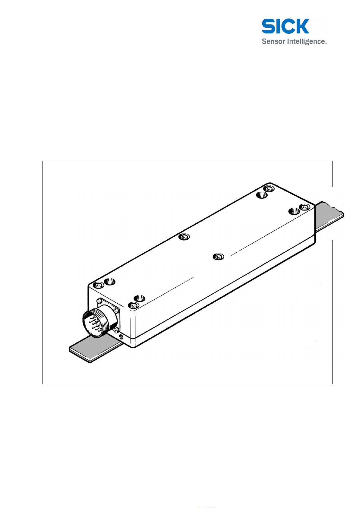
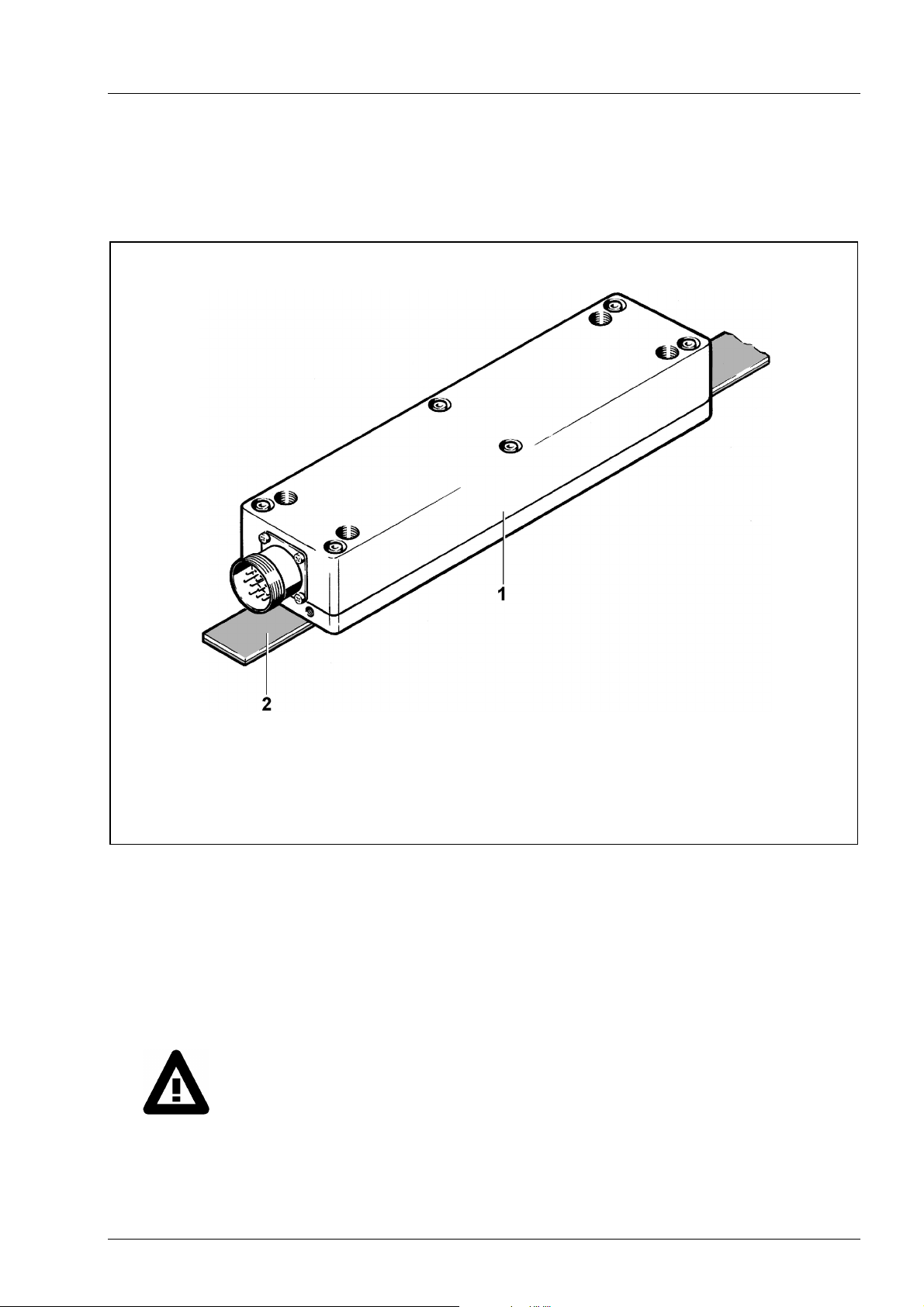
1 Sensor
2 Scale (magnetic strip)
Fig. 1-1 LinCoder
®
length measuring system
Dear Customer,
Dear Engineer,
You are about to mount a SICK LinCoder® System.
These operating instructions are intended to give you the knowledge which is
necessary for you to be able to carry out the mounting rapidly and correctly.
Please read these instructions through carefully and pay particular attention to the
advice and warning notes!
LinCoder® L 230 02-2019
Subject to change without notice 1
8019664/13GU
Page 6

Foreword
The LinCoder® System from SICK is a contactless, absolute length measuring system.
The measuring system is suitable for length measurement up to maximum of 40 metres,
both indoors and outdoors under normal ambient condition.
The measuring system comprises at least two parts:
– the scale
– the sensor
Scale
The scale – referred to below as the magnetic strip – comprises a magnetized plastic
strip which, at the factory, is laminated to a (ferromagnetic) steel strip.
The plastic strip contains the absolute length information magnetized on in the form of a
12-bit code.
Sensor
The sensor substantially comprises a rectangular aluminium housing
with a flanged plug or PG outlet.
In the application, the sensor is guided over the magnetic strip.
The sensor registers the information magnetized onto the magnetic strip and
from this determines a defined absolute length value.
The absolute position data are transmitted from and by the sensor to a control system or
to a host computer.
If you have any questions in relation to the LinCoder
answer them.
The telephone number will be found on the inside front cover of these operating
instructions.
®
System, we shall be pleased to
SICK STEGMANN GmbH
2 Subject to change without notice
8019664/13GU
LinCoder® L 230 02-2019
Page 7
General Advice
2 General Advice
2.1 Validity
These operating instructions apply to the LinCoder® L 230 contactless,
absolute length measuring system.
The configuration of the length measuring system is specific to a customer, that is to
say the syste
measured length.
2.2 Proper use
The LinCoder® L 230 length measuring system may be used only for the purpose
corresponding to its design – the determination of length or distance information.
Any further use or use going beyond this counts as improper and may lead to
personal injury or damage to property.
m is composed of a sensor and a magnetic strip which depends on the
2.3 Symbols and their meaning
Text which is identified with this symbol contains very important advice, also including
advice for averting health risks.
Observe these texts without fail.
Text which is identified with this symbol contains very important advice, also including
advise for preventing damage to property.
Observe these texts without fail.
This symbol indicates text which contains comments/advice or tips.
This bullet identifies the descriptions of actions which you should carry out.
LinCoder® L 230 02-2019
Subject to change without notice 3
8019664/13GU
Page 8

Safety Advice
3 Safety advice
3.1 Personal protection
The LinCoder® System operates exclusively with safe low voltages and, because of its
low inherent weight, represents a virtually negligible potential hazard. Nevertheless, the
measuring system may pose a threat in conjunction with further devices, machines or
plant.
Therefore, please observe the following advice:
Switch off all the devices/machines/plant affected by mounting
Depressurize pneumatic/hydraulic devices/machines/plant before mounting or
If necessary, set up warning signs in order to prevent the inadvertent starting
or repair.
If appropriate, isolate the devices/machines/plant from the mains.
repair.
up of the devices/machines/plant.
Do not under any circumstances start up the length measuring system
– with faulty safety equipment and/or
– with damaged components/modules (for example damaged plug connectors).
In these cases, isolate the system from the mains.
Ensure that, during the defect or the repair, the system cannot inadvertently be
connected to the mains. If necessary, set up warning signs.
After completing the repair work, carry out a test run of the system and check
the correct functioning of the safety equipment.
Observe the relevant professional safety and accident prevention regulations
when carrying out the mounting/repair work.
Prevent hands or fingers being able to get between sensor and magnetic strip, if
necessary by means of covers or the like.
Check the correct function of the safety equipment (for example the emergency
off push buttons) of the higher-order devices/machines/plant at regular intervals.
4 Subject to change without notice
8019664/13GU
LinCoder® L 230 02-2019
Page 9

Safety Advice
3.2 Device safety
The LinCoder® System is a quality product produced in accordance with the recognized
industrial regulations and meets the quality requirements of ISO 9001.
The system left the manufacturing plant in perfect condition with regard to safety.
In order to maintain this condition, as installer you must carry out your task in accor-
dance with the descriptions in these instructions, technically correctly and with the
greatest possible precision.
In addition, we assume that you have sound knowledge in mechanical, precision engineering and electrical engineering.
Use the length measuring system only for the purpose corresponding to its de-
sign.
Switch off the devices/machines/plant affected by mounting.
If appropriate, isolate the devices/machines/plant from the mains.
Depressurize pneumatic/hydraulic devices/machines/plant before mounting.
If necessary, set up warning signs, in order to prevent inadvertent starting up of
the devices/machines/plant.
Take care, for example in the case of long mounting lengths, that no parts of the
plant penetrate into the mounting area.
Lay the data cable from the sensor to the controller in such a way that it
– does not remain hanging during operation when moving over the measure-
ment length;
– is not crushed, kinked or otherwise damaged;
– does not run directly beside power lines or through relatively strong alternat-
ing electromagnetic fields.
In the case of electrical welding work which is carried out in the immediate vi-
cinity of the LinCoder
damage to the measuring system from high induced currents.
®
System, switch off its supply voltage, in order to rule out
Never open the housing of the sensor.
Opening the sensor impairs the functional reliability and leads to the
cancellation of the guarantee or guarantee claims.
Use only undamaged/fault-free tools and components for the mounting work.
Do not start up the LinCoder
®
System if any parts are damaged.
Following the mounting of the measuring system, and before releasing the
devices/machines/plant affected by it to the production process, carry out a test
run.
Avoid intense external magnetic fields acting on and ferromagnetic foreign
bodies (for example iron filings) being deposited on the magnetic strip.
LinCoder® L 230 02-2019
Subject to change without notice 5
8019664/13GU
Page 10
Testing the system components
4 Testing the system components
4.1 Goods inward inspection
Check
– directly after delivery, the parts of the measuring system for any transport damage
and deficiencies.
– with reference to the accompanying delivery note, the number of parts and that all
the small parts are present.
Do not leave any parts in the packaging.
4.2 Scope of supply
– Sensor
– Magnetic strip (sold by the metre)
– Operating
Accessories: see Chapter 12.2 Accessories
instructions for LinCoder® L 230
4.3 Complaints
Claims for compensation which relate to transport damage can only be considered valid if
the delivery company is notified without delay.
For returns (because of transport damage/repairs), prepare a damage report
immediately and send the parts back to the manufacturing plant, if possible in the
original packaging.
Attach the following information to the return:
– Name and address of the recipient
– Reference/Order/Part number
– Description of the defect
4.4 Guarantee
For the LinCoder® L 230 length measuring system, we give a guarantee period in accordance with the sales contract.
The general guarantee conditions of SICK STEGMANN GmbH apply.
6 Subject to change without notice
8019664/13GU
LinCoder® L 230 02-2019
Page 11

5 System description
5.1 Construction of the system components
System Description
Fig. 5-1 Scanning unit (sensor)
1 Basic housing body
2 Fastening holes
3 Cable outlet
Fig. 5-2 Construction of the plastic magnetic strip (sc
LinCoder® L 230 02-2019
Subject to change without notice 7
ale)
1 Dou
2 Steel strip
3 Plastic magneti
ble-sided adhesive tape
c strip
8019664/13GU
Page 12

System Description
5.2 Functional principle
The LinCoder® L 230 length measuring system comprises a magnetic strip and a sensor.
The magnetic strip represents the scale for a distance of up to 40 metres.
The absolute information is magnetized onto the strip in a sequential 12-bit code. In order
to achieve as high a resolution and accuracy as possible, a so-called incremental track is
also magnetized onto the magnetic strip, that is to say north and south poles are always
present alternately.
The magnetic strip is laminated by the manufacturer onto a ferromagnetic strip (steel
strip) which, firstly, serves as a magnetic return path and, secondly, serves as a
dimensionally stable mounting aid. The magnetic strip can therefore be bonded directly
onto a ferromagnetic carrier without any restriction, without there being any influence on
the magnetization. Depending on the composition of the carrier material (for the magnetic
strip) at the customer, the magnetic strip is supplied with an appropriate double-sided
adhesive tape, which is already bonded to one side of the steel strip by the manufacturer.
A contactless magnetic sensor with integrated evaluation electronics and corresponding
interface is led over the measurement path, and its position is output with a resolution of
1 µm/10 µm/156.25 m.
The sensor outputs its information to the control system either via an SSI interface
(synchronous serial interface) or via a HIPERFACE
interface).
®
interface (high performance
8 Subject to change without notice
8019664/13GU
LinCoder® L 230 02-2019
Page 13

Ambient Conditions
6 Ambient conditions
The LinCoder® System has been conceived for normal operating conditions. Therefore,
some restrictions have to be observed for its mounting and subsequent operation.
• Take care that
– the measuring system is mounted in accordance with the operating instructions
listed below.
– during operation, no foreign bodies – in particular ferromagnetic bodies – can be
deposited on the magnetic strip.
– the measurement system is not exposed to severe temperature fluctuations.
– the coefficient of thermal expansion of the carrier material (device/machine/plant)
agrees approximately with that of the stainless steel strip of the magnetic strip.
– no external magnetic
uring system.
– the measuring system or individual parts of the system are employed in accordance
with the characteristic values specified in the technical data.
Non-compliance with the operating instructions, or use outside the specified
characteristic values, can have a negative influence on the accuracy of the system.
fields of more that 64 mT (640 Oe; 52 kA/m) act on the meas-
The use of the measuring
place only after discussions with the manufacturer.
system under the influence of radioactive radiation may take
LinCoder® L 230 02-2019
Subject to change without notice 9
8019664/13GU
Page 14

Mounting Advice
7 Operating instructions
Because of the many possible areas of use and mounting arrangements of the
LinCoder
As a specialist, you can yourself solve specific tasks
cases after consultation with the manufacturer.
®
System, we can give only general advice.
or applications on site, or in specific
Before mounting, it is absolutely necessary to take note of the safety advice and
warning notes under
3 Safety advice
Comply exactly with the predefined installation dimensions.
In order to mount the sensor, use only screws, nuts, washers and spring rings
made of non-ferrous material (non-magnetic materials).
Never open the sensor.
Opening the sensor impairs the functional reliability and leads to cancellation of
the guarantee and guarantee claims.
10 Subject to change without notice
8019664/13GU
LinCoder® L 230 02-2019
Page 15

7.1 Mounting options
Mounting Advice
Fig. 7-1 Mounting options
The LinCoder
LinCoder® L 230 02-2019
®
System can be mounted and operated in all three axes.
Subject to change without notice 11
8019664/13GU
Page 16

Mounting Advice
7.2 Mounting arrangement
8
Fig. 7-2 Mounting arrangement for sensor and magnetic strip
1 Carrier for the sensor (from the customer)
2 Carrier for the magnetic strip (from the customer)
3 Identification of magnetic strip start
4 Cable outlet/plug connection of the sensor
5 Sensor
6 Fixing of the sensor optionally from above or from
below
7 Magnetic strip
8
Direction of travel for increasing counting sequence
1 Strip start
2 Strip end
Fig. 7-3 Distances covered
The mounting arrangement must ensure that the sensor can overtravel the start and finish of the
magnetic tape by at least 50 mm; this enables the complete measurement length of the tape to be
registered. The start of the tape is marked by a coloured dot. The arrow indicates the direction of
travel which results in an increasing code sequence. Due to the way the system operates, the magnetic tape is always 130 mm longer than the measurement length required.
12 Subject to change without notice
A = Scanning range, length 130 mm
X <
50 mm unequivocal measurement
range
X > 50 mm fault message
8019664/13GU
LinCoder® L 230 02-2019
Page 17

7.3 Mounting tolerances
Mounting Advice
1 Sensor
2 Magnetic strip
Fig. 7-4 Mounting tolerances
The operational relia
other things) compliance with the mounting tolerances.
Fig. 7-4 shows that the sensor is to be mounted at a distance of 1 mm parallel to the
magnetic strip (nominal distance). From this, a deviation of at most +/- 0.8 mm in the Z direction (distance between sensor and magnetic strip: 0.2 mm to 1.8 mm*) is permitted.
The lateral deviation of the sensors from the centre line of the magnetic strip (Y direction)
must be at most +/- 1 mm over the entire measurement length.
* between 1.8 mm and 3.5 mm, jumps in the position are undefined, at > 3.5 mm a fault
message is output.
LinCoder® L 230 02-2019
bility and accuracy of the measuring system assumes (amongst
Subject to change without notice 13
8019664/13GU
Page 18

Mounting/Disassembly/Expansion
8 Mounting/Disassembly/Expansion
In the following description, we assume that you have read through the preceding
chapter carefully and that, during the mounting/disassembly work, you will observe
the safety advice and the warning notes.
Note that the following descriptions are only general examples, since we do not know
the actual mounting situation on site.
Please adapt the examples to your mounting situation.
Before carrying out the mounting, take note of the dimensions and sizes under
12 Technical data.
14 Subject to change without notice
8019664/13GU
LinCoder® L 230 02-2019
Page 19

Mounting/Disassembly/Expansion
8.1 Mounting the sensor
1 2
1 Mounting from above
2 Mounting from below
Fig. 8-1 Mounting options for the sensor
The sensor is to be mounted on that part of the device/machines/plant whose travel represents the future measurement path.
Mounting can be carried out either from above, using four M8 screws, from below, using
four M8 screws (and nuts from above) or from below using four M6 screws.
Taking into account the conditions and the dimensions specified in Fig. 8-1, either drill
four clearance holes (diameter 8.5 mm) or four tapping holes (diameter 5 mm) into the
sensor mounting plate.
If necessary, cut four M6 threads into the sensor mounting plate.
Position the sensor in such a way that the plug or cable outlet points in the direction of
the start of the measurement path, i.e. opposite direction to the direction the arrow is
pointing on the magnet strip.
LinCoder® L 230 02-2019
Subject to change without notice 15
8019664/13GU
Page 20

Mounting/Disassembly/Expansion
Push the non-ferrous screws from the figure appropriately through the holes and
tighten them loosely.
If necessary, shift the sensor until its longitudinal axis runs parallel to the reference
edge of the part of the device/machine/plant.
Fix the sensor by tightening the fixing screws.
If necessary, mount dust-clearing brushes on the front and rear of the sensor.
If appropriate, connect the cable to the sensor and lay it as far as the control system.
Lay the cable such that it is not rubbed, crushed or sheared off.
When laying the cable, maintain a bending radius of greater than 80 mm.
This concludes the mounting of the sensor.
16 Subject to change without notice
8019664/13GU
LinCoder® L 230 02-2019
Page 21

Mounting/Disassembly/Expansion
8.2 Mounting the magnetic strip
We assume the surface(s), onto which the magnetic tape is glued, to be stable, even, dry,
free from dust, oil, oxides, release agents and other contamination. Cleaning agents such
as isopropanol/water (50/50), heptane, ethanol, acetone and MEK may be used to remove contamination. The cleaning agent must be chosen such that the substance used
does not attack the surface to be glued and does not leave any residues; basically, it depends on the materials to be cleaned. When cleaning metal surfaces with acetone, the
metal surface may cool down during the evaporation phase, and condensate may form. If
so, wait until the surface has dried again.
In order to fix the magnetic strip, we recommended, if not already supplied, the use of the
double-sided adhesive tape type 3M4611F (from Scotch). This adhesive tape is particularly suitable for bases made of steel, galvanized steel, aluminium and plastic. In order to
check the adhesive strength with other bases in advance, we will gladly provide a sample
on request.
Make the sensor travel over the measurement path and, by means of a plumb line or a
square, transfer the centre line of the sensor to the base. Identify this point by means
of a scriber, lead pencil or the like.
Connect the individual points by means of a rule, chalk line or with the aid of a laser
beam to form a continuous line. This line corresponds to the centre line of the measurement path.
If necessary, draw a second line at a distance of 12.5 mm from the centre line.
If appropriate, stick a double-sided adhesive tape over the complete magnetic strip
length, flat on the underside of the magnetic strip.
Lay the magnetic strip centrally on the centre line over its complete length. The point-
like marking on the magnetic strip must point in the direction of the start of the measurement path.
Fix the magnetic strip provisionally (for example with weights, non-ferrous screw
clamps) at a number of points.
Lift the magnetic strip upwards a little at the start of the measurement path and, in the
starting area, remove the protective film from the double-sided adhesive tape.
Stick the starting area of the magnetic strip exactly onto the centre line.
Stick the rest of the magnetic strip onto the base, by removing the fixing piece by
piece and pulling out the protective film sideways.
®
This concludes the mounting of the LinCoder
System.
LinCoder® L 230 02-2019
Subject to change without notice 17
8019664/13GU
Page 22

Mounting/Disassembly/Expansion
8.3 Disassembly of the LinCoder® System
Before you begin disassembling the LinCoder
– switch off all the devices/machines/plant affected by the disassembly.
– if appropriate, isolate the devices/machines/plant from the mains.
– Depressurize pneumatic/hydraulic devices/machines/plant.
If necessary, set up warning signs in order to prevent the inadvertent starting
up of the devices/machines/plant.
Disassemble
– the cable from the sensor to the control system,
– the sensor,
– the magnetic strip.
Treat the parts carefully, collect all the parts together – including the screws, nuts and
so on, and keep them for possible subsequent use.
®
System,
Inform the user of the device or the machine/plant that the measuring system
has been disassembled.
8.4 Expansion
Expanding an existing measurement system is possible only by removing the old and
mounting a new, longer magnetic
please take note of the descriptions in these operating instructions.
strip, because of the system used. In this case,
18 Subject to change without notice
8019664/13GU
LinCoder® L 230 02-2019
Page 23

Commissioning/Test run
9 Commissioning/test run
Following the mounting/expansion/repair, the device or the machine/plant should be subjected to a test run before it is released for the production process.
Remove all tools, aids or the like from the active area of the measuring system.
Check whether all parts of the measurement system are correctly and firmly installed.
Switch on all parts of the device/machine/ plant which have a functional relationship
with the measuring system.
If appropriate, activate the necessary safety equipment (for example shut-off
systems, warning lamps or the like).
Start up the device, the machine/plant, and check whether the sensor can move cor-
rectly over the measurement path.
Check whether the control system is receiving the data from the sensor and whether
the part of the device/machine/plant to which the sensor is fitted is reacting to the control signals.
Check the functioning of any emergency off buttons or other safety equipment
which may be present.
Only release systems for the production process which function without error.
LinCoder® L 230 02-2019
Subject to change without notice 19
8019664/13GU
Page 24

Faults/Repairs
10 Faults/Repairs
Like any te
exhibit malfunctions. The causes are often of a trivial nature and easy to rectify.
Before you make contact with us, we request that the first measure you take is to look
for the cause of the fault yourself.
In the following list, we have compiled the most frequent fault causes for you.
In the event of a system fault, please read through the listed causes carefully and
check whether one of these applies.
Should this list not help you further, please telephone us. The telephone number will
be found on the front inside cover of these operating instructions.
chnical system, the LinCoder® System can also fail as a result of faults or
10.1 Fault causes
– Plant or parts of the plant not switched on
– Cable not plugged in (correctly)
– Cable defective
– Plugs/sockets defective
– Centre mounted incorrectly (cable/plug outlet does not point to the start of the
measurement path, i.e. see direction of the arrow on the magnet strip)
– Positional tolerances not observed (Sensor mounted too high or too far removed
from the centre line of the measurement path)
– There is ferromagnetic material on or in the vicinity of the magnetic strip
– The magnetic strip has been mounted the wrong way round (marking not pointing
to the start of the measurement path)
– Information on the magnetic strip has been changed or erased by the action of ex-
ternal magnetic fields
– Power supply to the sensor not serviceable, or it is too weak
– Interfaces of control system and sensor not compatible
Once you have defined the cause of the fault unequivocally, please rectify it if it lies
within your capabilities.
20 Subject to change without notice
8019664/13GU
LinCoder® L 230 02-2019
Page 25

Faults/Repairs
10.2 Repairs
The repair work on the LinCoder® System is restricted, as far as you are concerned,
to the activities which you have also carried out during the mounting.
Before carrying out repairs, it is absolutely necessary to take note of:
3 Safety Advice,
7 Mounting Advice and
8 Mounting/Disassembly/Expansion
Before carrying out the repairs, switch off all the parts of the de-
vice/machine/plant that are affected.
Under no circumstances open the parts of the measuring system. Damaged parts
such as sensor or magnetic strip must be replaced.
In this regard, see:
12.1 LinCoder
®
ordering key.
Use only original SICK STEGMANN spare parts as replacement parts.
Following repair work, carry out a test run of the measuring system.
In this regard, see:
9 Commissioning/Test run.
LinCoder® L 230 02-2019
Subject to change without notice 21
8019664/13GU
Page 26

Maintenance/Cleaning
11 Maintenance/Cleaning
Before carrying out maintenance/cleaning work, switch off all the parts of the
device/machine/plant that are affected.
11.1 Maintenance
The LinCoder® System is a contactless measuring system and contains no moving
parts. Therefore it is basically maintenance-free.
Under rough operating conditions – above all outdoors – corrosion or material fatigue
phenomena (adhesive tape) may be produced by ambient influences.
Before this wear causes faults, the influences should be prevented by suitable measures.
Therefore, from time to time check the parts of the measuring system for damage.
Replace damaged parts only by original SICK STEGMANN spare parts.
Under no circumstances open the parts of the measuring system.
11.2 Cleaning
Do not use any scouring or corrosive cleaning agents.
Prevent liquids or moisture penetrating into the sensor.
Under no circumstances open parts of the measuring system.
22 Subject to change without notice
8019664/13GU
LinCoder® L 230 02-2019
Page 27

12 Technical data
12.1 Accessories
Connection Systems
Programming Tool for individual parametrizing of
HIPERFACE Encoders
Technical Data
LinCoder® L 230 02-2019
Subject to change without notice 23
8019664/13GU
Page 28

Technical data
12.2 General data
Measurement length Max. 40 m
Magnetic strip length
Reproducibility ± 10
Measurement accuracy typ. ± 0.3 mm/m at 20 °C
Max. speed of travel 6 m/s
Temperature expansion coefficient
Position and mounting tolerances see page 13:
Dimensions
Material sensor part AlMgSiPbF28
Working temperature range SSI 0 ... + 70 °C
Working temperature range HIPERFACE 0 ... + 60 °C
Storage temperature range - 40 ... + 100 °C
Fixing the magnetic tape with adhesive
tape (unprocessed)
Protection class IP 65
1)
steel strip
Tk
magnetic strip
steel strip
Technically necessary constant
Values Units
Measurement length
+ 130
1)
mm
m
16
m / °C /
m
7.3 Mounting tolerances
see page 26
12.3 Dimensional drawing
Tromaflex 928
Nr. 1.4435
10 months min. from date
code (yyww), at around 20°C
and 50% humidity
24 Subject to change without notice
8019664/13GU
LinCoder® L 230 02-2019
Page 29

Technical Data
Values Units
Position resolution 0 to 8.35 m²
)
0 to 40 m
Position repetition time 750 µs
Initialisation time 3500 ms
Supply voltage 10 ... 32 V
Max. power consumption 4.8 W
2)
longer measurement lengths on request
1
10
µm
µm
HIPERFACE
Periodic length
Position resolution
®
Values
5 3%
156.25
Units
mm
µm
(Periodic length /32=5mm/32)
Initialisation time 2500
Supply voltage 7...12
Max. operating current, no load 4.3
ms
V
W
Interface signals:
Process data channel
SIN, COS
REFSIN/REFCOS
Non-linearity within one sine/cosine cycle,
0.9...1.1
2.2...2.8
50
Vpp
V
µm
differential non-linearity
Parameter channel
External ma
gnetic fields
to EIA 485
External magnetic fields should not exceed 64 mT (640 Oe; 52kA/m) on the surface of
the gauge, since this can damage the coding on the gauge. Magnetic fields > 1 mT at the
measuring system affect the measurement accuracy.
Initial commissioning
The measurement path can start at any position between 0 m and 40 m. Therefore it will
be helpful, prior to initial commissioning, to align the electrical zero point to your intended
mechanical position. When operating with the SSI interface, this can be performed via the
SET input, for HIPERFACE variants, this can be programmed via software.
LinCoder® L 230 02-2019
Subject to change without notice 25
8019664/13GU
Page 30

Technical data
p
12.3 Dimensional drawing
Magnetic strip with double-sided
e.
Adhesive ta
Fig. 12-1 LinCoder® L 230 dimensions
26 Subject to change without notice
8019664/13GU
LinCoder® L 230 02-2019
Page 31

Technical Data
12.4 Connection details for HIPERFACE® and interfaces
12-pole round
connection for
PIN Colour Signal PIN Colour Signal
1 Blue GND 1 Black REFCOS
2 White Data (+) 2 Grey RS 485 (+)
3 Yellow Clock (+) 3 – N. C.
4 Grey RS 485 (+) 4 – N. C.
5 Green RS 485 (-) 5 White SIN
6 – N. C. 6 Brown REFSIN
7 – N. C. 7 Green RS 485 (-)
8 Red US (+) 8 Pink COS
9 Orange
10 Brown Data (-) 10 Blue GND
11 Purple Clock (-) 11 – N. C.
12 Black
* This input is use
on this terminal, the LinCoder position is set to 0.
Cable
d for electronic adjustment. By means of a high signal (Us) > 20 ms
For serial in-
terface
*
Set
**
V/R
12-pole
round con-
nector for
HIPERFACE®
9 – N. C. Screen
12 Red US
Cable
For
HIPERFACE
interface
®
** This output programmes the counting direction of the LinCoder. If not connected, this
input is “high”. If the LinCoder is moved from the start to the end of the magnetic strip,
it counts upwards. If the LinCoder is to count upwards from the end to the start of the
magnetic strip, this terminal must be connected permanently to “low” GND.
View on the plug side at the LinCoder
N.C.: = no connection
Screening via housing plug
Please observe the connection details of the measuring system without fail.
LinCoder® L 230 02-2019
Subject to change without notice 27
8019664/13GU
Page 32

8019664/13GU/2019-02-06 ∙ AB_07
Australia
Phone +61 3 9497 4100
1800 33 48 02 – tollfree
E-Mail sales@sick.com.au
Belgium/Luxembourg
Phone +32 (0)2 466 55 66
E-Mail info@sick.be
Brasil
Phone +55 11 3215-4900
E-Mail sac@sick.com.br
Ceská Republika
Phone +420 2 57 91 18 50
E-Mail sick@sick.cz
China
Phone +852-2763 6966
E-Mail ghk@sick.com.hk
Danmark
Phone +45 45 82 64 00
E-Mail sick@sick.dk
Deutschland
Phone +49 211 5301-301
E-Mail kundenservice@sick.de
España
Phone +34 93 480 31 00
E-Mail info@sick.es
France
Phone +33 1 64 62 35 00
E-Mail info@sick.fr
Great Britain
Phone +44 (0)1727 831121
E-Mail info@sick.co.uk
India
Phone +91–22–4033 8333
E-Mail info@sick-india.com
Israel
Phone +972-4-999-0590
E-Mail info@sick-sensors.com
Italia
Phone +39 02 27 43 41
E-Mail info@sick.it
Japan
Phone +81 (0)3 3358 1341
E-Mail support@sick.jp
Nederlands
Phone +31 (0)30 229 25 44
E-Mail info@sick.nl
Norge
Phone +47 67 81 50 00
E-Mail austefjord@sick.no
Österreich
Phone +43 (0)22 36 62 28 8-0
E-Mail office@sick.at
Polska
Phone +48 22 837 40 50
E-Mail info@sick.pl
Republic of Korea
Phone +82-2 786 6321/4
E-Mail info@sickkorea.net
Republika Slovenija
Phone +386 (0)1-47 69 990
E-Mail office@sick.si
România
Phone +40 356 171 120
E-Mail office@sick.ro
Russia
Phone +7 495 775 05 34
E-Mail info@sick-automation.ru
Schweiz
Phone +41 41 619 29 39
E-Mail contact@sick.ch
Singapore
Phone +65 6744 3732
E-Mail admin@sicksgp.com.sg
Suomi
Phone +358-9-25 15 800
E-Mail sick@sick.fi
Sverige
Phone +46 10 110 10 00
E-Mail info@sick.se
Taiwan
Phone +886 2 2375-6288
E-Mail sales@sick.com.tw
Türkiye
Phone +90 216 587 74 00
E-Mail info@sick.com.tr
United Arab Emirates
Phone +971 4 8865 878
E-Mail info@sick.ae
USA/Canada/México
Phone +1(952) 941-6780
1 800-325-7425 – tollfree
E-Mail info@sickusa.com
More representatives and agencies
in all major industrial nations at
www.sick.com
SICK AG | Waldkirch | Germany | www.sick.com
 Loading...