

Page 1
FOR THE HARSHEST CONDITIONS –
THE HEAVY-DUTY LINEAR ENCODER
A
KH53 LINEAR ENCODERS
B
C
D
E
F
G
H
I
Additional information
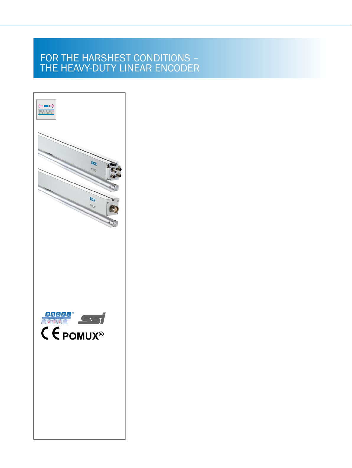
Product description
The POMUX KH53 non-contact linear encoder can measure absolute lengths up
to 1,700 m. The encoder consists of two
main components: The non-contact read
head determines the absolute position
using a series of measuring elements
attached along the measurement path.
Each measuring element consists of a
number of permanent magnets. Since
the distances between the magnets are
unique, they can be used to develop an
absolute measuring code. No reference
At a glance
• Non-contact length measurement
– maintenance-free, rugged, long
service life
• High reproducibility (0.3 mm / 1 mm),
high system resolution (0.1 mm)
• SSI and PROFIBUS interfaces
• Determination of absolute position
• Measuring lengths of up to 1,700 m
possible
Your benets
• After installation, the system is
immediately available and completely
maintenance-free, which leads to time
and cost savings
• Reliable determination of position
under harshest ambient conditions
such as the effects of dirt, dust, fog,
shock, and vibration
run is required due to the absolute position being determined. The read head
is passed parallel to these measuring
elements at a distance of 25 mm or
55 mm. With a measuring length of
up to 1,700 m, the KH53 is ideal for
use in cranes, in storage and conveyor
systems, and for railed vehicles. Due to
the non-contact technology, this system
works wear-free even in harsh ambient
conditions,so that a long lifetime is
ensured.
• Can be used in the harshest ambient
conditions
• High traversing speedds of up to
6.6 m/s
• Distance tolerance between read
head and measuring element: up to
55 mm ± 20 mm possible
• High efciency and productivity levels
• Time savings – no reference run nec-
essary on initial commissioning due
to absolute position measurement
• Accurate positioning even with high
mounting tolerances
Detailed technical data. . . . . . . . . J-645
Ordering information. . . . . . . . . . . J-647
J
K
L
Dimensional drawings . . . . . . . . . J-651
Pin assignment ...............J-652
Implementation ..............J-654
Switch settings ...............J-655
General information ...........J-655
Position tolerance . . . . . . . . . . . . . J-655
Recommended accessories. . . . . J-656
J-644
ENCODERS | SICK 8015560/2015-09-01
Subject to change without notice
Page 2

LINEAR ENCODERS KH53
Fields of application
• Position determination for container cranes in container
terminals
• Positioning of the trolley on cranes
Detailed technical data
Performance
Measuring length
Measuring range
Interfaces
Resolution
Reproducibility
Max. traversing speed
Measurement accuracy
1)
An error message appears if the max. traversing speed is exceeded or the read head cannot detect a measuring element (with SSI FF FF FE hex).
2)
Related to the start of a measuring element if a position tolerance of ± 1 mm is maintained based on the nominal distance in the N and Y directions. ME = Length of
the measuring element (see illustration on page J-652), Tu = ambient temperature in °C, Tk = coefcient of thermal expansion (see "Mechanical Data" table on page
J-646).
1)
2)
0 m ... 1,700 m 0 m ... 548 m
38 m, 107 m, 354 m, 1,700 m 54 m, 548 m
SSI and PROFIBUS
0.1 mm
0.3 mm 1 mm
6.6 m/s
± 1000 + ME (Tu –25 °C) Tk µm ± 2000 + ME (Tu –25 °C) Tk µm
• Positioning of automated guided vehicles in storage and
conveyor systems
KH53 KH53 Advanced
A
B
C
D
Electrical data
Initialization time
Position forming time
PROFIBUS 1.1 ms
Supply voltage
Electrical connection
PROFIBUS 3 x M12 male connectors
SSI
RS422 interface for parameterizing
Interface digital, serial
Default setting SSI standard
SSI power consumption
PROFIBUS DP
Electrical interface
Address setting (node number)
Protocol
Bus termination
SET (electronic adjustment)
Encoder prole
Data transmission rate (baud rate)
Status information
PROFIBUS power consumption in operation
1)
According to ISO13849. This product is a standard product and does not constitute a safety component as dened in the Machinery Directive. Calculation based on
nominal load of components, average ambient temperature of 40°C, frequency of use 8760 h/a. All electronic failures are considered hazardous. For more informa-
tion, see document no. 8015532.
2 s
SSI 0.8 ms
10 … 32 V
SSI Cable
M23 male connector
Four wire transmission, asynchronous, full-duplex
Data format: 1 start bit, 8 data bits, 1 stop bit, no parity
Data protocol: ASCII, Baud rate 9,600
SSI 24 bit, gray
RS 422 OFF
250 mA
RS485 (as per EN 50 170-2 (DIN 19245 Parts 1–3) electrically isolated by optocoupler
0 ... 127 (hex switch or protocol)
PROFIBUS DP basic functions (DP-V0)
Via external male connectors
Via protocol
Proles for encoders (07hex) – Class 2
9.6 kBaud ...12 Mbaud (autodetect)
Operation (LED green), bus activity (LED red)
2.5 W
E
F
G
H
I
J
K
Subject to change without notice
ENCODERS | SICK8015560/2015-09-01
J-645
L
Page 3

A
B
C
D
E
F
KH53 LINEAR ENCODERS
MTTFd: mean time to dangerous failure
SSI Measuring range up to 38 m: 45 years
Measuring range up to 107 m: 40 years
Measuring range up to 354 m: 31 years
Measuring range up to 1,700 m:
21 years
PROFIBUS Measuring range up to 38 m: 40 years
Measuring range up to 107 m: 35 years
Measuring range up to 354 m: 28 years
1)
According to ISO13849. This product is a standard product and does not constitute a safety component as dened in the Machinery Directive. Calculation based on
nominal load of components, average ambient temperature of 40°C, frequency of use 8760 h/a. All electronic failures are considered hazardous. For more informa-
tion, see document no. 8015532.
Measuring range up to 1,700 m: 20 years
1)
Mechanical data
KH53 KH53 Advanced
Mass
Read head 38 2.4 kg –
Read head 107 2.7 kg –
Read head 354 3.6 kg –
Read head 1,700 5.2 kg –
Read head 54 – 4.4 kg
Read head 548 – 6.7 kg
Measuring element 0.5 kg/m 0.65 kg/m
Length of measuring element
Coefcient of thermal expansion
Position tolerance (see diagram on Page
J-655)
Read head material
Measuring element material
See tables on Page J-647 and Page J-649
28 µm/°C/m
± 10 mm ± 20 mm
AIMgSiPbF28
AIMgSiO,5F22
1)
Measuring range up to 54 m: 34 years
1)
Measuring range up to 548 m: 22 years
1)
1)
Measuring range up to 54 m: 30 years
1)
Measuring range up to 548 m: 20 years
1)
1)
1)
1)
1)
1)
G
H
I
J
K
Ambient data
1)
EMC
Enclosure rating
SSI read head with cable IP 66
SSI read head with screw-in system IP 65 (with mating connector tted)
Read head with PROFIBUS connectors IP 67 (with mating connector tted)
Operating temperature range
Read head storage temperature range
Resistance to shocks
Read head 30 g/10 ms
Measuring element 50 g / 10 ms
Resistance to vibrations
Read head 10 g/20 ... 250 Hz
Measuring element 30 g / 20 ... 250 Hz
1)
The EMC according to the standards quoted is achieved if shielded connecting cables are used.
According to EN 61000-6-2 and EN 61000-6-4
–20 ... +60 °C –30 … +70 °C
–40 … +85 °C
According to EN 61000-2-27
According to DIN EN 61000-2-6
L
J-646
ENCODERS | SICK 8015560/2015-09-01
Subject to change without notice
Page 4
SSI ordering information
Length of measuring element
LINEAR ENCODERS KH53
incl. separation
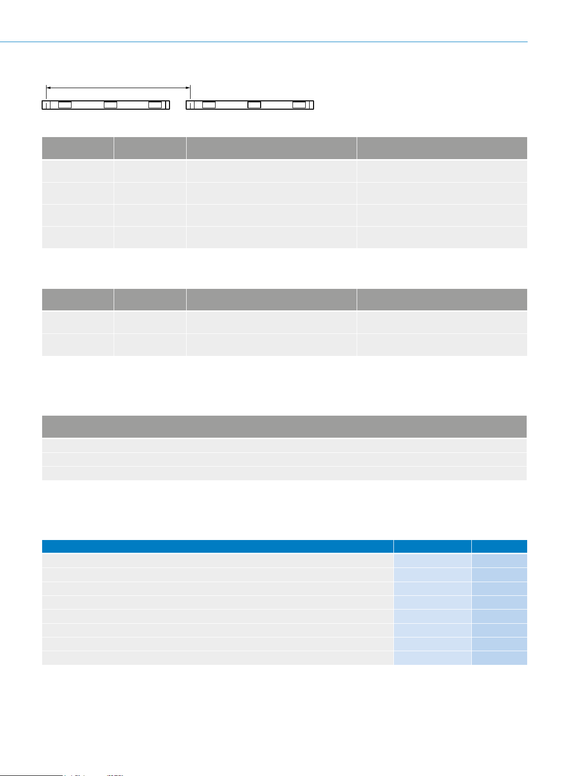
Dimensions and calculation table - KH53
Measuring range
up to
39.90 m 0.886 m 2.304 m
107.40 m 1.051 m 1.8688 m
351.20 m 1.376 m 2.5088 m
1676.40 m 2.026 m 1.9072 m
The dimensions given are slightly rounded.
Read head length Length of measuring element including
distance
Identication letters A1 ... ≤ A18
Identication letters B1 ... ≤ B58
Identication letters C1 ... ≤ C141
Identication letters D1 ... ≤ D880
Measurement and calculation table - KH53 Advanced
Measuring range
up to
53.50 m 1.58 m 1.408 m
546.40 m 2.506 m 2.3552 m
The dimensions given are slightly rounded.
Read head length Length of measuring element including
distance
Identication letters F1 ... ≤ F39
Identication letters G1 ... ≤ G233
Mounting systems per measuring element
(suggestion)
4 clamp holders or 8 mounting brackets
3 clamp holders or 6 mounting brackets
4 clamp holders or 8 mounting brackets
3 clamp holders or 6 mounting brackets
Mounting systems per measuring element
(suggestion)
3 clamp holders or 6 mounting brackets
4 clamp holders or 8 mounting brackets
A
B
C
D
E
Calculation example for a measurement distance of 100 m
Selected system with measuring range up to 107 m
Number of measuring elements required = measurement path + length of the read head / length of measurement element (according to table above)
Number of measuring elements required = 101.051 m / 1.8688 m = 54.07
Ordering amount therefore 55 measuring elements and 55 * 3 = 165 clamp holders
If two separate measurement paths are to be implemented, then please order 2 x 55 measuring elements (not 110 measuring elements)
Attention! For position determination, the read head must not travel beyond the last measuring element.
KH53 length measurement systems (absolute, linear)
Measuring range up to 38 meters
Description Type Part no.
Read head 38, SSI, cable 1.5 m KHK53-AXR00038 1030048
Read head 38, SSI, cable 3.0 m KHK53-AXS00038 1030049
Read head 38, SSI, cable 5.0 m KHK53-AXT00038 1030050
Read head 38, SSI, cable 10.0 m KHK53-AXU00038 1030051
Read head 38, SSI, M23 male, 12 pin KHK53-AXB00038 1030052
Measuring element up to 38 m, coded
Measuring element up to 38 m, universally codeable
Assembly gauge 38 KHM53-XXX00038 1030057
1)
When ordering replacements for individual defective measuring elements, please enter the code for the measuring element in question .
2)
For the temporary replacement of defective, coded measuring elements.
1)
2)
KHT53-XXX00038 1030055
KHU53-XXX00038 1030056
F
G
H
I
J
K
Subject to change without notice
ENCODERS | SICK8015560/2015-09-01
J-647
L
Page 5

KH53 LINEAR ENCODERS
Measuring range up to 107 meters
A
B
C
D
E
F
Description Type Part no.
Read head 107, SSI, cable 1.5 m KHK53-AXR00107 1030058
Read head 107, SSI, cable 3.0 m KHK53-AXS00107 1030059
Read head 107, SSI, cable 5.0 m KHK53-AXT00107 1030060
Read head 107, SSI, cable 10.0 m KHK53-AXU00107 1030061
Read head 107, SSI, M23 male device connector, 12 pin KHK53-AXB00107 1030062
Measuring element up to 107 m, coded
Measuring element up to 107 m, universally codeable
Assembly gauge 107 KHM53-XXX00107 1030067
1)
When ordering replacements for individual defective measuring elements, please enter the code for the measuring element in question .
2)
For the temporary replacement of defective, coded measuring elements.
Measuring range up to 354 meters
Description Type Part no.
Read head 354, SSI, cable 1.5 m KHK53-AXR00107 1030068
Read head 354, SSI, cable 3.0 m KHK53-AXS00354 1030069
Read head 354, SSI, cable 5.0 m KHK53-AXT00354 1030070
Read head 354, SSI, cable 10.0 m KHK53-AXU00354 1030071
Read head 354, SSI, M23 male device connector, 12 pin KHK53-AXB00354 1030072
Measuring element up to 354 m, coded
Measuring element up to 354 m, universally codeable
Assembly gauge 354 KHM53-XXX00354 1030077
1)
When ordering replacements for individual defective measuring elements, please enter the code for the measuring element in question .
2)
For the temporary replacement of defective, coded measuring elements.
1)
2)
1)
2)
KHT53-XXX00107 1030065
KHU53-XXX00107 1030066
KHT53-XXX00354 1030075
KHU53-XXX00354 1030076
G
H
I
J
K
Measuring range up to 1,700 meters
Description Type Part no.
Read head 1700, SSI, cable 1.5 m KHK53-AXR01700 1030078
Read head 1700, SSI, cable 3.0 m KHK53-AXS01700 1030079
Read head 1700, SSI, cable 5.0 m KHK53-AXT01700 1030080
Read head 1700, SSI, cable 10.0 m KHK53-AXU01700 1030081
Read head 1700, SSI, M23 male device connector, 12 pin KHK53-AXB01700 1030082
Measuring element up to 1,700 m, coded
Measuring element up to 1,700 m, universally codeable
Assembly gauge 1700 KHM53-XXX01700 1030087
1)
When ordering replacements for individual defective measuring elements, please enter the code for the measuring element in question .
2)
For the temporary replacement of defective, coded measuring elements.
1)
2)
KHT53-XXX01700 1030085
KHU53-XXX01700 1030086
L
J-648
ENCODERS | SICK 8015560/2015-09-01
Subject to change without notice
Page 6

KH53 advanced length measurement systems (absolute, linear)
Length of measuring element
LINEAR ENCODERS KH53
Measuring range up to 54 meters
Description Type Part no.
Read head 54, SSI, cable 5.0 m KHK53-AXT00054 1035442
Read head 54, SSI, M23 male device connector, 12 pin KHK53-AXB00054 1035443
Measuring element up to 54 m, coded
Measuring element up to 54 m, universally codeable
Assembly gauge 54 KHM53-XXX00054 1035447
1)
When ordering replacements for individual defective measuring elements, please enter the code for the measuring element in question .
2)
For the temporary replacement of defective, coded measuring elements.
Measuring range up to 548 meters
Description Type Part no.
Read head 548, SSI, cable 5.0 m KHK53-AXT00548 1035448
Read head 548, SSI, M23 male device connector, 12 pin KHK53-AXB00548 1035449
Measuring element up to 548 m, coded
Measuring element up to 548 m, universally codeable
Assembly gauge 548 KHM53-XXX00548 1035453
1)
When ordering replacements for individual defective measuring elements, please enter the code for the measuring element in question .
2)
For the temporary replacement of defective, coded measuring elements.
1)
2)
1)
2)
KHT53-XXX00054 1035445
KHU53-XXX00054 1035446
KHT53-XXX00548 1035451
KHU53-XXX00548 1035452
A
B
C
D
E
PROFIBUS ordering information
incl. separation
Dimensions and calculation table - KH53
Measuring range
up to
39.90 m 0.905 m 2.304 m
107.40 m 1.070 m 1.8688 m
351.20 m 1.395 m 2.5088 m
1676.40 m 2.045 m 1.9072 m
The dimensions given are slightly rounded.
Read head length Length of measuring element including
distance
Identication letters A1 ... ≤ A18
Identication letters B1 ... ≤ B58
Identication letters C1 ... ≤ C141
Identication letters D1 ... ≤ D880
Measurement and calculation table - KH53 Advanced
Measuring range
up to
53.50 m 1.599 m 1.408 m
546.40 m 2.525 m 2.3552 m
The dimensions given are slightly rounded.
Read head length Length of measuring element including
distance
Identication letters F1 ... ≤ F39
Identication letters G1 ... ≤ G233
Mounting systems per measuring element
(suggestion)
4 clamp holders or 8 mounting brackets
3 clamp holders or 6 mounting brackets
4 clamp holders or 8 mounting brackets
3 clamp holders or 6 mounting brackets
Mounting systems per measuring element
(suggestion)
3 clamp holders or 6 mounting brackets
4 clamp holders or 8 mounting brackets
F
G
H
I
J
Subject to change without notice
K
ENCODERS | SICK8015560/2015-09-01
J-649
L
Page 7

KH53 LINEAR ENCODERS
Calculation example for a measurement distance of 100 m
A
B
C
D
E
F
G
Selected system with measuring range up to 107 m
Number of measuring elements required = measurement path + length of the read head / length of measurement element (according to table above)
Number of measuring elements required = 101.070 m / 1.8688 m = 54.08
Ordering amount therefore 55 measuring elements and 55 * 3 = 165 clamp holders
If two separate measurement paths are to be implemented, then please order 2 x 55 measuring elements (not 110 measuring elements)
Attention! For position determination, the read head must not travel beyond the last measuring element.
KH53 length measurement systems (absolute, linear)
Measuring range up to 38 meters
Description Type Part no.
Read head 38, PROFIBUS DP KHK53-PXF00038 1036163
Measuring element up to 38 m, coded
Measuring element up to 38 m, universally codeable
Assembly gauge 38 KHM53-XXX00038 1030057
1)
When ordering replacements for individual defective measuring elements, please enter the code for the measuring element in question .
2)
For the temporary replacement of defective, coded measuring elements.
Measuring range up to 107 meters
Description Type Part no.
Read head 107, PROFIBUS DP KHK53-PXF00107 1036164
Measuring element up to 107 m, coded
Measuring element up to 107 m, universally codeable
Assembly gauge 107 KHM53-XXX00107 1030067
1)
When ordering replacements for individual defective measuring elements, please enter the code for the measuring element in question .
2)
For the temporary replacement of defective, coded measuring elements.
1)
2)
1)
2)
KHT53-XXX00038 1030055
KHU53-XXX00038 1030056
KHT53-XXX00107 1030065
KHU53-XXX00107 1030066
H
I
J
K
L
Measuring range up to 354 meters
Description Type Part no.
Read head 354, PROFIBUS DP KHK53-PXF00354 1036165
Measuring element up to 354 m, coded
Measuring element up to 354 m, universally codeable
Assembly gauge 354 KHM53-XXX00354 1030077
1)
When ordering replacements for individual defective measuring elements, please enter the code for the measuring element in question .
2)
For the temporary replacement of defective, coded measuring elements.
Measuring range up to 1,700 meters
Description Type Part no.
Read head 1700, PROFIBUS DP KHK53-PXF01700 1036166
Measuring element up to 1,700 m, coded
Measuring element up to 1,700 m, universally codeable
Assembly gauge 1700 KHM53-XXX01700 1030087
1)
When ordering replacements for individual defective measuring elements, please enter the code for the measuring element in question .
2)
For the temporary replacement of defective, coded measuring elements.
J-650
ENCODERS | SICK 8015560/2015-09-01
1)
2)
1)
2)
KHT53-XXX00354 1030075
KHU53-XXX00354 1030076
KHT53-XXX01700 1030085
KHU53-XXX01700 1030086
Subject to change without notice
Page 8

KH53 advanced length measurement systems (absolute, linear)
61.1 (2.41)
Bending radius > 80 (3.15)
57 (2.24)
LINEAR ENCODERS KH53
Measuring range up to 54 meters
Description Type Part no.
Read head 54, PROFIBUS DP KHK53-PXF00054 1036167
Measuring element up to 54 m, coded
Measuring element up to 54 m, universally codeable
Assembly gauge 54 KHM53-XXX00054 1035447
1)
When ordering replacements for individual defective measuring elements, please enter the code for the measuring element in question .
2)
For the temporary replacement of defective, coded measuring elements.
Measuring range up to 548 meters
Description Type Part no.
Read head 548, PROFIBUS DP KHK53-PXF00548 1036168
Measuring element up to 548 m, coded
Measuring element up to 548 m, universally codeable
Assembly gauge 548 KHM53-XXX00548 1035453
1)
When ordering replacements for individual defective measuring elements, please enter the code for the measuring element in question .
2)
For the temporary replacement of defective, coded measuring elements.
Dimensional drawing SSI read head (dimensions in mm)
1)
2)
1)
2)
KHT53-XXX00054 1035445
KHU53-XXX00054 1035446
KHT53-XXX00548 1035451
KHU53-XXX00548 1035452
A
B
C
D
E
(0.31)
51 (2.01)
Plugged on
Bending radius
≥ 80 (3.15)
8
20
(0.79)
F
With 12-pin connector
G
Length read head
With PG outlet
H
I
J
Subject to change without notice
K
ENCODERS | SICK8015560/2015-09-01
J-651
L
Page 9

Length read head
13.5
51 (2.01)
+0.3
(0.30)
Ø 10
Ø 23.5
29.05
A
KH53 LINEAR ENCODERS
Dimensional drawing PROFIBUS read head (dimensions in mm)
±1
(0.53)
B
C
D
E
F
Mounting slot designed for
non-magnetic M6 DIN 933
screws.
Dimensional drawing for measuring element
(0.39)
15
(0.59)
Length measuring element (ME)
(1.14)
3
(0.12)
(0.93)
24
(0.28)
6
(0.24)
10
(0.39)
Ø 7
Pin assignment for SSI interface
Mounting slot
5.7
7.7
(0.22)
3.5
(0.14)
10.2
6.2
(0.24)
61.1 (2.41)
A
A
(0.40)
+0.2
G
H
I
J
K
View of M23 male device connector on SSI encoder
PIN Signal Wire colors
1 GND Blue Ground connection
2 Data + White Interface signals
3 Clock + Yellow Interface signals
4 R x D + Gray RS-422 programming cables
5 R x D – Green RS-422 programming cables
6 T x D + Pink RS-422 programming cables
7 T x D – Black RS-422 programming cables
8 + U
9 N. C. Orange Not connected
10 Data – Brown Interface signals
11 Clock – Violet Interface signals
12 N. C. – Not connected
N. C. = Not Connected.
Other interfaces on request.
S
Explanation
(cable outlet)
Red Operating voltage
L
J-652
ENCODERS | SICK 8015560/2015-09-01
Subject to change without notice
Page 10

Pin assignment for PROFIBUS interface
LED1
re
een
LINEAR ENCODERS KH53
A
d
Male connector, 4
pin
1 – – US (24 V) Operating voltage 10 ... 32 V
3 – – 0 V (GND) Ground (0 V)
– – 4 B B cable PROFIBUS DP (out)
– – 2 A A cable PROFIBUS DP (out)
– 4 – B B cable PROFIBUS DP (in)
– 2 – A A cable PROFIBUS DP (in)
– – 1 2P5
– – 3 2M
4 1 – Not connected –
2 3 – Not connected –
– 5 5 Screen Housing potential
1)
Use for external bus termination.
Male connector, 5
pin
LED2
gr
Female connector
5 pin
Signal Explanation
1)
1)
+ 5 V (potential free)
0 V (potential free)
B
C
D
E
F
G
H
I
J
K
Subject to change without notice
ENCODERS | SICK8015560/2015-09-01
J-653
L
Page 11

S1
S2
A
B
C
D
E
KH53 LINEAR ENCODERS
Implementation
DP functionalities
according to PROFIBUS-DP basic functionalities.
DP services
• Data exchange (Write_Read_Data)
• Address allocation (Set_Slave_Address)
• Control commands (Global_Control)
• Reading inputs (Read_Inputs)
• Reading outputs (Read_Outputs)
• Reading diagnostic data (Slave_Diagnosis)
• Sending parameter data (Set_Param)
• Checking conguration data (Chk_Cong)
Communication
• Cyclic master-slave data trafc.
Safety mechanisms
• Transfer of data with HD = 4.
• Time monitoring of data trafc.
Conguration
Settings according to encoder prole
• Counting direction (CW, CCW)
• Class 2 functionality (ON, OFF)
• Scaling function (ON, OFF)
Conguration
Setting the formats (IN/OUT) for the cyclic data exchange
through a conguration byte (K-1).
2 words IN/OUT data (I-1/O-1)
4 words IN/OUT data (I-1, I-2, I-3/O-1)
Data exchange: – Input data (IN)
I-1 Position value 1) 4 bytes
I-2 Speed (0.1 m/min)
I-3 Time stamp
Data exchange: – Output data (out)
O-1 PRESET – Value 1) 4 bytes
Diagnostic information
• Station related diagnostic (63 bytes according to encoder
prole Class 2)
Setting: – PRESET value
The PRESET function is used for commissioning and the allocation of a particular position value to current physical positioning.
The following settings are possible:
• Via software: – (see Output Data)
2)
2 bytes
2)
2 bytes
1)
2)
F
G
H
I
J
• “Activation of SSA service”
• Selection of the station address
1)
In accordance with encoder prole.
2)
Manufacturer specic function.
Setting: – Counting direction
• Via hardware via hex switch S2
• Via software via telegram
Count direction increasing:
Movement of the encoder from prole item n in the direction of
prole item n+1
2)
2)
Setting: – Station address
• Via hardware via hex switch S1/S2
• Via software via telegram
Setting by software only occurs with prior activation of the “SSA
service”.
Device specic le (*.GS_)
The *.GS_ le is designed for automatic commissioning of the
encoder. Within it all the characteristic features of the device
are dened.
STEG05F6.GSD German
STEG05F6.GSE English
K
L
J-654
ENCODERS | SICK 8015560/2015-09-01
Subject to change without notice
Page 12

Switch settings
Zero mark on the read head
Zero
Connector or cable outlet always at this position
last permanent magnet
The following settings are possible via hex switches:
S1/S2 Address setting (0 ... 127)
S2 Counting direction (CW/CCW)
Access is via a screw connection on the side of the read head
male connector.
General information
The KH53 PROFIBUS is an absolute length measurement
system with a resolution of 100 µm. The bus coupling is inside
the encoder and is an interface connection as PROFIBUS DP
slave according to EN 50170 Vol. 2. Implementation is with the
Siemens PROFIBUS ASIC SPC3.
The KH53 PROFIBUS contains all Class 2 functionalities ac-
cording to the encoder prole (V1.1)
Implementation of the encoder is as a DP slave with the DP
basic functions.
LINEAR ENCODERS KH53
Status information via LEDs
LED-1 Bus activity (red)
LED-2 Operating voltage (green)
Conformity with PROFIBUS DP is ensured by a PNO certied test
center.
The following options are available:
• M12 plug connector system
A
B
C
D
Position tolerances
Start of measurement path
Read head
Measuring element
End of measurement path
Last measuring element
Assumed position of the
E
F
G
Read head
H
I
Subject to change without notice
J
K
ENCODERS | SICK8015560/2015-09-01
J-655
L
Page 13

11
22
All dimensions in mm (inch)
11
22
All dimensions in mm (inch)
A
KH53 LINEAR ENCODERS
The operating reliability and accuracy of the measuring system depends on (amongst other things) compliance with the position
tolerances. Magnetic or magnetizable materials are not permitted within 80 mm of the encoder or the measuring element.
KH53
KH53 Advanced
B
C
D
E
F
1 Read head
2 Measuring element
)
±10
±0.39
(0.98
N = 25
±10
(0.39)
)
±20
±0.0.79
N = 55
(2.17
Y
±20
(0.79)
1 Read head
2 Measuring element
Y
G
Only use non ferro-magnetic materials for the assembly base of the read head.
A separation distance of 80 mm must be observed for ferro-magnetic materials (e.g., iron).
H
I
J
K
Recommended accessories
Mounting systems
Mounting brackets and plates
Mounting bracket
Figure Brief description Type Part no.
Mounting bracket for KH53 measuring elements, without mounting hardware for the
base
Clamp and alignment brackets
Terminal brackets
Figure Brief description Type Part no.
Spacer for KH53 measuring elements, without mounting hardware for the base BEF-KHA-KHT53 2042468
BEF-WK-KHT53 2029159
L
J-656
ENCODERS | SICK 8015560/2015-09-01
Subject to change without notice
Page 14

Connectors
LINEAR ENCODERS KH53
Plug connectors and cables
Connecting cables with female connector
Figure Brief description Length
Head A: M12 female connector, 4-pin, straight
Head B: cable
Cable: for power supply, suitable for drag chain, PVC, unshielded,
4 x 0.25 mm², Ø 5.0 mm
Head A: M12 female connector, 5-pin, straight
Head B: cable
Cable: suitable for drag chain, PROFIBUS DP, PUR, halogen-free, shielded,
2 x 0.34 mm², Ø 8.0 mm
Head A: M23 female connector, 12-pin, straight
Head B: cable
Cable: SSI, RS-422, suitable for drag chain, PUR, shielded, 4 x 2 x 0.25 mm²
+ 2 x 0.5 mm² + 2 x 0.14 mm², Ø 7.8 mm
Connecting cables with male connector
Figure Brief description Length
Head A: M12 male connector, 5-pin, straight, B-coded
Head B: cable
Cable: PROFIBUS DP, suitable for drag chain, PUR, halogen-free, shielded,
2 x 0.34 mm², Ø 8.0 mm
Wire shielding: AL-PT foil, total shield, tin-plated C shield
Type Part no.
of
cable
5 m DOL-1204-G05M 6009866
5 m DOL-1205-G05MQ 6026006
10 m DOL-1205-G10MQ 6026008
1.5 m DOL-2312-G1M5MA1 2029200
3 m DOL-2312-G03MMA1 2029201
5 m DOL-2312-G05MMA1 2029202
10 m DOL-2312-G10MMA1 2029203
20 m DOL-2312-G20MMA1 2029204
30 m DOL-2312-G30MMA1 2029205
Type Part no.
of
cable
5 m STL-1205-G05MQ 6026005
10 m STL-1205-G10MQ 6026007
12 m STL-1205-G12MQ 6032635
A
B
C
D
E
F
Female connectors (ready to assemble)
Figure Brief description Type Part no.
Head A: M12 female connector, 4-pin, straight, unshielded, for power supply, for cable
diameter 4 mm ... 6 mm
Head B: -
Head A: M12 female connector, 5-pin, straight, B-coded, PROFIBUS DP, shielded, for
cable diameter 4 mm ... 9 mm
Head B: -
Head A: M23 female connector, 12-pin, straight, HIPERFACE®, SSI, incremental, shielded, for cable diameter 5.5 mm ... 10.5 mm
Head B:
Operating temperature: –20 °C ... +130 °C
DOS-1204-G 6007302
DOS-1205-GQ 6021353
DOS-2312-G 6027538
G
H
I
J
K
Subject to change without notice
ENCODERS | SICK8015560/2015-09-01
J-657
L
Page 15

KH53 LINEAR ENCODERS
Cables (ready to assemble)
A
B
C
D
E
F
Figure Brief description Length
of
cable
Head A: cable
Head B: cable
Cable: PROFIBUS DP, suitable for drag chain, PUR, shielded, 2 x 0.25 mm²,
Ø 8.0 mm
Head A: cable
Head B: cable
Cable: SSI, suitable for drag chain, PUR, halogen-free, shielded,
4 x 2 x 0.25 mm² + 2 x 0.5 mm² + 2 x 0.14 mm², Ø 7.8 mm
Head A: cable
Head B: cable
Cable: suitable for drag chain, PUR, halogen-free,
shielded, UV and saltwater resistant, 4 x 2 x 0.25 mm² + 2 x 0.5 mm²
+ 2 x 0.14 mm², Ø 7.8 mm
Other plug connectors and cables
Figure Brief description Type Part no.
Head A: M12 male connector, 4-pin, straight, B-coded
Cable: PROFIBUS DP, terminator
Male connector (ready to assemble)
Figure Brief description Type Part no.
Head A: M12 male connector, 5-pin, straight, B-coded, PROFIBUS DP, shielded, for cable
diameter 4 mm ... 9 mm
Head B: -
Head A: M23 male connector, 12-pin, straight, HIPERFACE®, SSI, incremental, RS-422,
shielded, for cable diameter 5.5 mm ... 10.5 mm
Head B:
Operating temperature: –20 °C ... +130 °C
By the
meter
Type Part no.
LTG-2102-MW 6021355
LTG-2512-MW 6027531
LTG-2612-MW 6028516
STE-END-Q 6021156
STE-1205-GQ 6021354
STE-2312-G 6027537
G
H
I
J
K
Additional accessories
Programming and conguration tools
Figure Brief description Type Part no.
Programming tool for ATM60, ATM90 and KH53 SSI PGT-01-S 1030111
- For additional accessories, please see page K-668 onwardsw
L
J-658
ENCODERS | SICK 8015560/2015-09-01
Subject to change without notice
Page 16

LINEAR ENCODERS KH53
A
B
C
D
E
F
G
H
I
Subject to change without notice
J
K
ENCODERS | SICK8015560/2015-09-01
J-659
L
 Loading...