

Page 1
BETRIEBSANLEITUNG/OPERATING INSTRUCTIONS
ISD400
IR-Datenübertragungssystem
IR Data Transmission System
D
GB
Page 2

Betriebsanleitung
Inhalt/Contents
ISD400
Inhalt/Contents
D Seite 2–60
GB Page 61–119
Dieses Werk ist urheberrechtlich geschützt.
Die dadurch begründeten Rechte bleiben bei
der Firma SICK AG. Eine Vervielfältigung des
Werkes oder von Teilen dieses Werkes ist
nur in den Grenzen der gesetzlichen Bestimmungen des Urheberrechtsgesetzes zulässig.
Eine Abänderung oder Kürzung des Werkes
ist ohne ausdrückliche schriftliche Zustimmung der Firma SICK AG untersagt.
2 © SICK AG • Deutschland • Alle Rechte vorbehalten 8012620/YYZ3/2016-08-01
Page 3

Betriebsanleitung
Inhalt
ISD400
Inhalt
1 Zu diesem Dokument ............ 6
1.1 Funktion dieses
Dokuments ....................... 6
1.2 Verwendete Symbole ....... 7
2 Produktbeschreibung ............ 9
2.1 Sicherheitshinweise ...... 10
2.1.1 Sicherheitsstandard .. 10
2.1.2 Bestimmungsgemäße
Verwendung ............... 10
2.2 Gerätebezeichnung ....... 13
2.3 Funktionsprinzip ........... 14
2.4 Unterstützte Protokolle . 15
2.5 Signalverzögerung ........ 16
3 Montage ............................... 17
3.1 Gegenseitige
Beeinflussung ............... 17
3.2 Mechanische
Anbringung .................... 19
8012620/YYZ3/2016-08-01 © SICK AG • Deutschland • Alle Rechte vorbehalten 3
Page 4

Betriebsanleitung
Inhalt
ISD400
3.3 Kaskadierung von
mehreren
Übertragungsstrecken .. 21
3.4 Elektrischer Anschluss . 22
4 Bedienfeld mit LCD-Anzeige24
4.1 Menüebene 1
PROFIBUS ...................... 25
4.2 Menüebene 2 bzw. 3
PROFIBUS ...................... 26
4.3 Parameterliste
PROFIBUS ...................... 27
4.4 Menüebene 1 Ethernet 29
4.4.1 Ethernet-Busstatus .... 29
4.5 Menüebene 2 bzw. 3
Ethernet ......................... 30
5 Inbetriebnahme ................... 35
5.1 Gerätekonfiguration ..... 35
5.2 Bus-Terminierung bei
PROFIBUS ...................... 36
5.3 Ausrichtung ................... 36
4 © SICK AG • Deutschland • Alle Rechte vorbehalten 8012620/YYZ3/2016-08-01
Page 5

Betriebsanleitung
Inhalt
ISD400
5.4 Sende-LED über MF-
Eingang ausschalten .... 40
5.5 Anzeige orange Status-
LED ................................. 40
6 Technische Daten ................ 42
6.1 Datenblatt ...................... 42
6.2 Maßbilder ...................... 47
6.3 Zubehör ......................... 48
6.3.1 Anschlusstechnik für
PROFIBUS-Schnitt-
stelle ........................... 48
6.3.2 Ausrichtzubehör ......... 55
7 Troubleshooting ................... 58
8012620/YYZ3/2016-08-01 © SICK AG • Deutschland • Alle Rechte vorbehalten 5
Page 6

Betriebsanleitung
Zu diesem Dokument
ISD400
1 Zu diesem
Dokument
Bitte lesen Sie dieses Kapitel sorgfältig, bevor Sie mit der Dokumentation und dem ISD400 arbeiten.
1.1 Funktion dieses Dokuments
Diese Betriebsanleitung leitet das
technische Personal des Maschinenherstellers bzw. Maschinenbetreibers zur sicheren Montage,
Parametrierung, Elektroinstallation,
Inbetriebnahme sowie zum Betrieb
und zur Wartung des optischen
Datenübertragungssystems ISD400
an.
6 © SICK AG • Deutschland • Alle Rechte vorbehalten 8012620/YYZ3/2016-08-01
Page 7

Betriebsanleitung
Zu diesem Dokument
ISD400
Diese Betriebsanleitung leitet nicht
zur Bedienung der Maschine an, in
die das optische Datenübertragungssystem integriert ist oder wird.
Informationen hierzu enthält die
Betriebsanleitung der Maschine.
Hinweis
Handeln
Sie …
1.2 Verwendete Symbole
Hinweise informieren Sie über
Besonderheiten des Geräts.
Handlungsanweisungen sind durch
einen Pfeil gekennzeichnet. Lesen
und befolgen Sie Handlungsanweisungen sorgfältig.
8012620/YYZ3/2016-08-01 © SICK AG • Deutschland • Alle Rechte vorbehalten 7
Page 8

Betriebsanleitung
Zu diesem Dokument
ACHTUNG
ISD400
Warnhinweis!
Ein Warnhinweis weist Sie auf konkrete oder potenzielle Gefahren hin.
Dies soll Sie vor Unfällen bewahren.
Lesen und befolgen Sie Warnhinweise sorgfältig!
8 © SICK AG • Deutschland • Alle Rechte vorbehalten 8012620/YYZ3/2016-08-01
Page 9

Betriebsanleitung
Produktbeschreibung
ISD400
2 Produkt-
beschreibung
Dieses Kapitel informiert Sie über
die besonderen Eigenschaften des
ISD400. Es beschreibt den Aufbau
und die Arbeitsweise des Gerätes,
insbesondere die verschiedenen
Betriebsarten.
Lesen Sie dieses Kapitel auf
jeden Fall, bevor Sie das Gerät
montieren, installieren und in
Betrieb nehmen.
8012620/YYZ3/2016-08-01 © SICK AG • Deutschland • Alle Rechte vorbehalten 9
Page 10

Betriebsanleitung
Produktbeschreibung
ISD400
2.1 Sicherheitshinweise
2.1.1 Sicherheitsstandard
Das optische Datenübertragungssystem ISD400 ist unter Beachtung
geltender Sicherheitsnormen entwickelt, gefertigt und geprüft worden. Es entspricht dem Stand der
Technik.
2.1.2 Bestimmungsgemäße Verwendung
Das optische Datenübertragungssystem ISD400 ist für die optische
Übertragung von Daten im Infrarotbereich konzipiert und entwickelt
worden.
10 © SICK AG • Deutschland • Alle Rechte vorbehalten 8012620/YYZ3/2016-08-01
Page 11

Betriebsanleitung
Produktbeschreibung
ACHTUNG
ISD400
Der Schutz von Betriebspersonal
und Gerät ist nicht gewährleistet,
wenn das Gerät nicht entsprechend seiner bestimmungsgemäßen Verwendung eingesetzt wird.
Hinweis
Für eine einwandfreie Funktion ist
ein unterbrechungsfreier Sichtkontakt zwischen den beiden
ISD400 erforderlich. Sollte es in der
Applikation zu Unterbrechungen des
Sichtkontakts kommen (z. B. bei
Wartungsarbeiten) wird empfohlen,
zuvor über den MF-Eingang die
Sende-LED der beiden ISD400
auszuschalten. Hierdurch werden
Störungen in der Kommunikation
verhindert.
8012620/YYZ3/2016-08-01 © SICK AG • Deutschland • Alle Rechte vorbehalten 11
Page 12

Betriebsanleitung
Produktbeschreibung
ISD400
Einsatzgebiete
Das ISD400 ist für folgende Einsatzgebiete geeignet:
Automatisierte Hochregallager
Stationäre Datenübertragung
zwischen Gebäuden
Überall, wo eine Datenübertra-
gung zu und von festen oder bewegten Objekten (Sichtverbindung) auch auf größere Distanz
(bis zu 180 m) gefordert ist.
12 © SICK AG • Deutschland • Alle Rechte vorbehalten 8012620/YYZ3/2016-08-01
Page 13

Betriebsanleitung
Produktbeschreibung
Tab. 1:
zeichnung
ISD400
2.2 Gerätebezeichnung
Gerätebe-
Datenschnittstelle
Gerätebezeichnung
PROFIBUS ISD400-
1111
ISD4001121
Ethernet ISD400-
BestellNr.
Heizung
1042286 ohne
1043511 mit
1046119 ohne
6111
ISD4006121
1046120 mit
8012620/YYZ3/2016-08-01 © SICK AG • Deutschland • Alle Rechte vorbehalten 13
Page 14
Betriebsanleitung
Produktbeschreibung
Abb. 1:
prinzip
ISD400
2.3 Funktionsprinzip
Damit sich die Geräte bei der Datenübertragung im Duplex-Betrieb
nicht gegenseitig beeinflussen, verwenden sie zwei Frequenzpaare.
Diese sind über das Bedienfeld ein-
Funktions-
stellbar.
Der Empfangspegel wird an beiden
Geräten überprüft und kann an
einer Bargraph- Anzeige abgelesen
werden. Bei Absinken des
Empfangspegels unter einen bestimmten Wert, z. B. bei zunehmender Verschmutzung der Optik, wird
ein Warnausgang aktiviert. Alle Arbeiten am Gerät (Montieren, An-
14 © SICK AG • Deutschland • Alle Rechte vorbehalten 8012620/YYZ3/2016-08-01
Page 15

Betriebsanleitung
Produktbeschreibung
ISD400
schließen, Ausrichten, Anzeige-/Bedienelemente) werden komfortabel
von oben durchgeführt.
2.4 Unterstützte Protokolle
Folgende Datenprotokolle können
mit der ISD400 übertragen werden:
PROFIBUS:
Es können PROFIBUS, MPI und
PROFIsafe übertragen werden.
Ethernet:
Es können EtherNet TCP/IP,
EtherNet/IP, PROFINET und
PROFIsafe übertragen werden.
Hinweis
Bei der Übertragung von Ethernetprotokollen sind die maximale
optische Datenübertragungsrate
8012620/YYZ3/2016-08-01 © SICK AG • Deutschland • Alle Rechte vorbehalten 15
Page 16

Betriebsanleitung
Produktbeschreibung
ISD400
von 3 Mbit/s, sowie der maximale
Ein- und Ausgangsdatenpuffer von
jeweils 8 kByte der ISD400 zu
berücksichtigen.
Zur Reduzierung des Datenverkehrs
können externe Switches oder
Router eingesetzt werden.
2.5 Signalverzögerung
Die im Anhang "Technische Daten"
dokumentierten Signalverzögerungen können in Grenzfällen eine
Anpassung der Bus-Timingparameter in der Steuerung
erfordern.
16 © SICK AG • Deutschland • Alle Rechte vorbehalten 8012620/YYZ3/2016-08-01
Page 17

Betriebsanleitung
Montage
ISD400
3 Montage
Dieses Kapitel beschreibt die Vorbereitung und Durchführung der
Montage des optischen Datenübertragungssystems ISD400. Die Geräte können liegend oder stehend
auf die Halterung montiert werden.
3.1 Gegenseitige Beeinflussung
In manchen Anwendungen ist ein
Betrieb zweier Datenlichtschrankenstrecken nebeneinander notwendig.
Hierfür ist ein minimaler Abstand
8012620/YYZ3/2016-08-01 © SICK AG • Deutschland • Alle Rechte vorbehalten 17
einzuhalten.
Page 18
Betriebsanleitung
Montage
Abb. 2:
Abstände
ISD400
d
d
s
= s
min
= Mindestabstand
min
= Max. benötigte Reichweite
max
max
x tan (0,5°)
18 © SICK AG • Deutschland • Alle Rechte vorbehalten 8012620/YYZ3/2016-08-01
Bei Parallelmontage der Datenlichtschranke ISD400 mit einem
Distanzsensor der DME, bzw.
DL100 Produktfamilie, ist ein
Mindestabstand von 100 mm
Page 19

Betriebsanleitung
Montage
ISD400
einzuhalten (a>100 mm). Dieser
Mindestabstand ist unabhängig von
der maximalen Entfernung zwischen
den beiden ISD.
3.2 Mechanische Anbringung
Die Geräte sind so zu montieren,
dass bei minimalem Abstand die
optischen Achsen der beiden
Geräte übereinstimmen:
– Streckenabstand 0,2 ... 180 m:
Die beiden Geräte um 180°
zueinander gedreht montieren.
– Streckenabstand 3,0 … 180 m:
Die beiden Geräte können ohne
8012620/YYZ3/2016-08-01 © SICK AG • Deutschland • Alle Rechte vorbehalten 19
180°-Drehung montiert
werden.
Page 20
Betriebsanleitung
Montage
Abb. 3:
stehend
ISD400
Montage
ISD400
liegend und
Empfänger
Sender
Status-LED (Funktionsanzeige/
Pegelwarnung)
Optische Ausrichthilfe
(Fadenkreuz)
20 © SICK AG • Deutschland • Alle Rechte vorbehalten 8012620/YYZ3/2016-08-01
Page 21

Betriebsanleitung
Montage
ISD400
3.3 Kaskadierung von
mehreren
Übertragungsstrecken
Es können bis zu 2 Übertragungsstrecken in Reihe geschaltet
(kaskadiert) werden.
8012620/YYZ3/2016-08-01 © SICK AG • Deutschland • Alle Rechte vorbehalten 21
Page 22

Betriebsanleitung
Montage
ISD400
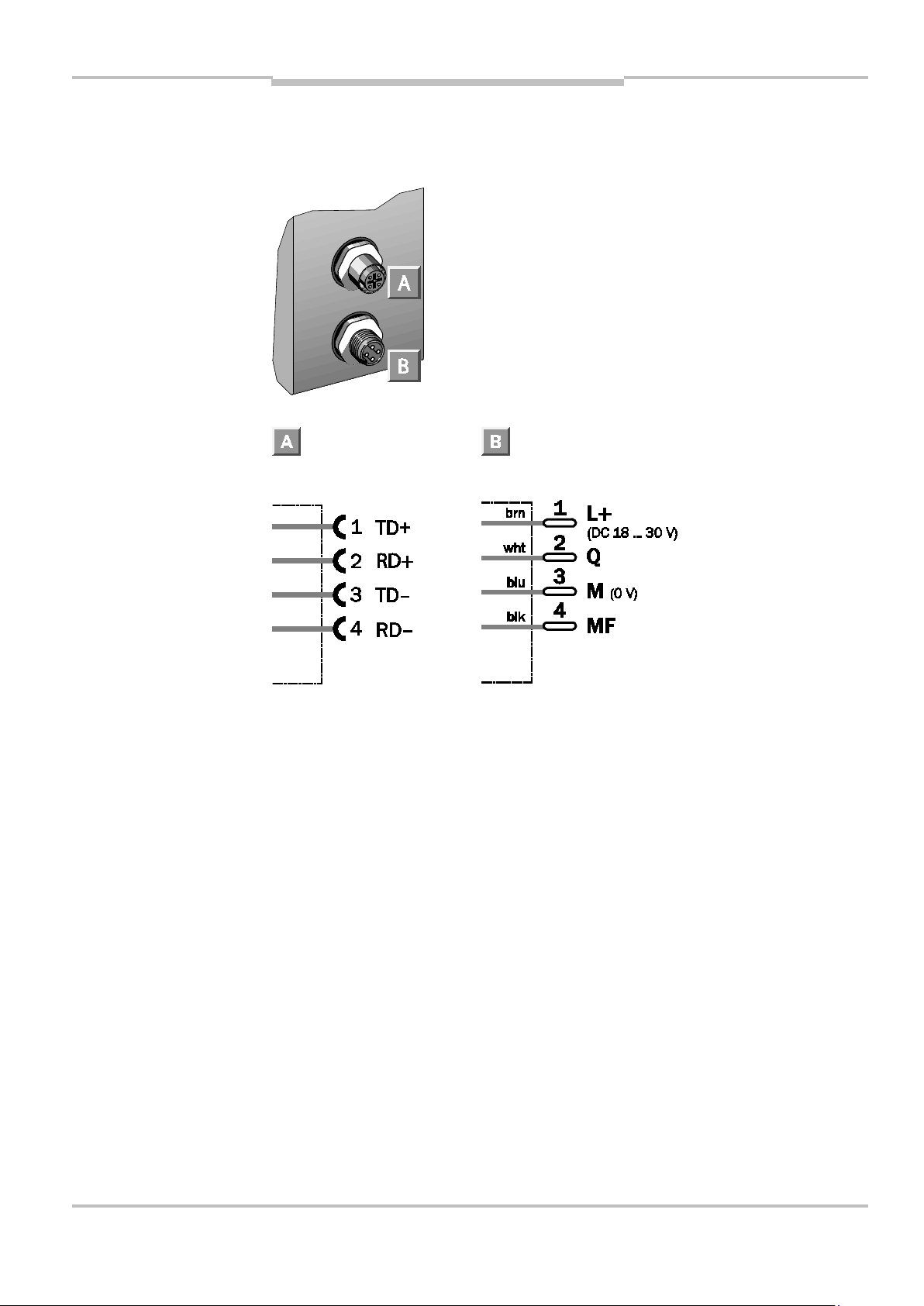
3.4 Elektrischer Anschluss
Abb. 4:
Anschluss-
art,
PROFIBUS
5-polig, 5-polig, 4-polig,
M12, M12, M12
Bus in Bus out
22 © SICK AG • Deutschland • Alle Rechte vorbehalten 8012620/YYZ3/2016-08-01
Page 23
Betriebsanleitung
Montage
ISD400
Abb. 5:
Anschluss-
art,
Ethernet
4-polig, 4-polig,
M12, M12
Ethernet
8012620/YYZ3/2016-08-01 © SICK AG • Deutschland • Alle Rechte vorbehalten 23
Page 24
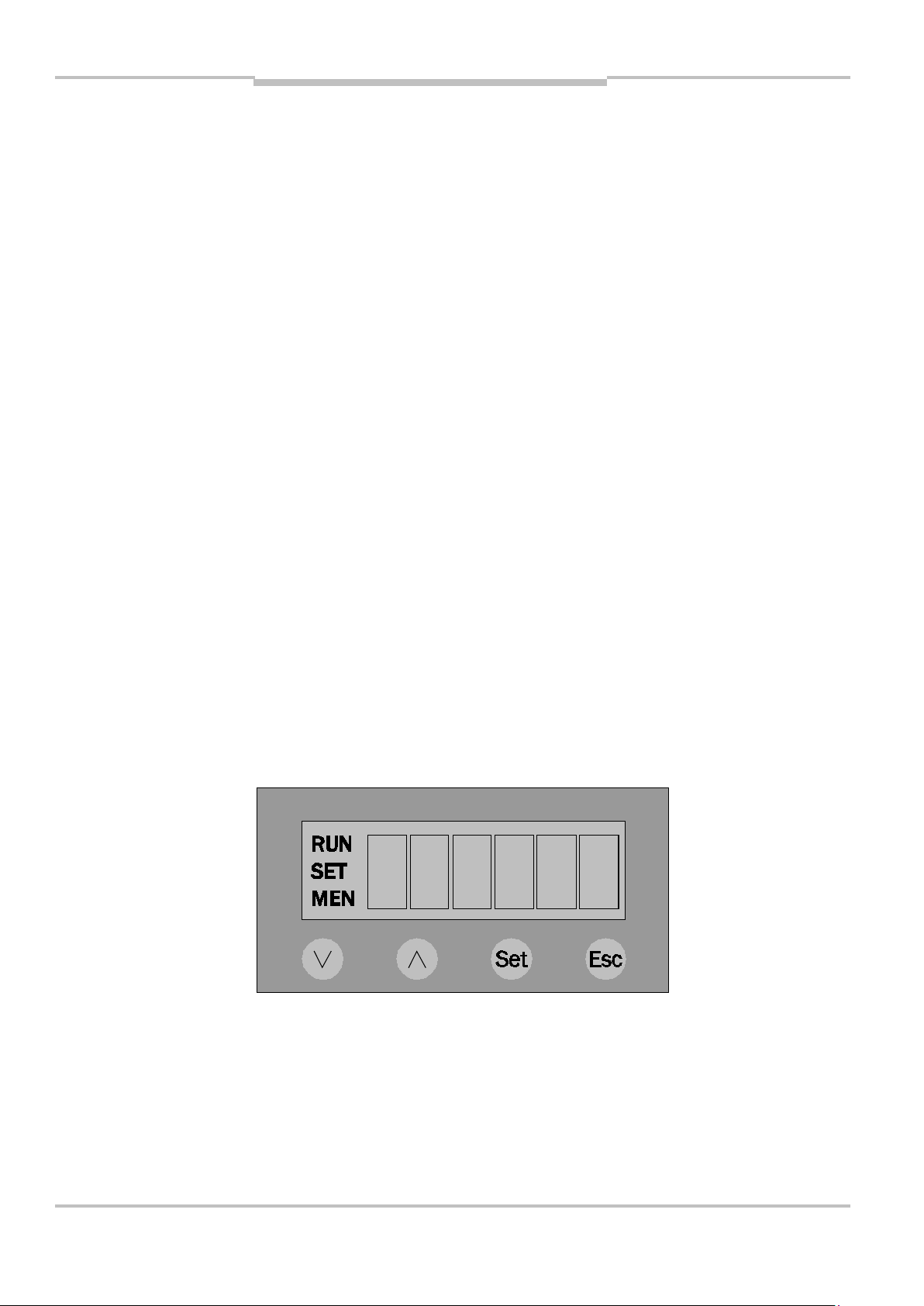
Bedienfeld mit LCD
-
Anzeige
Abb. 6:
Bedienfeld
Betriebsanleitung
ISD400
4 Bedienfeld mit LCD-
Anzeige
6 Segmente mit 5x7 Pixel
Pegelanzeige mit max. 20 Balken
(4 Segmente mit 7 Pixeln pro
Balken)
Mode-Anzeigen mit: RUN, SET,
MEN
4 Tasten DOWN, UP, SET, ESC
24 © SICK AG • Deutschland • Alle Rechte vorbehalten 8012620/YYZ3/2016-08-01
Page 25
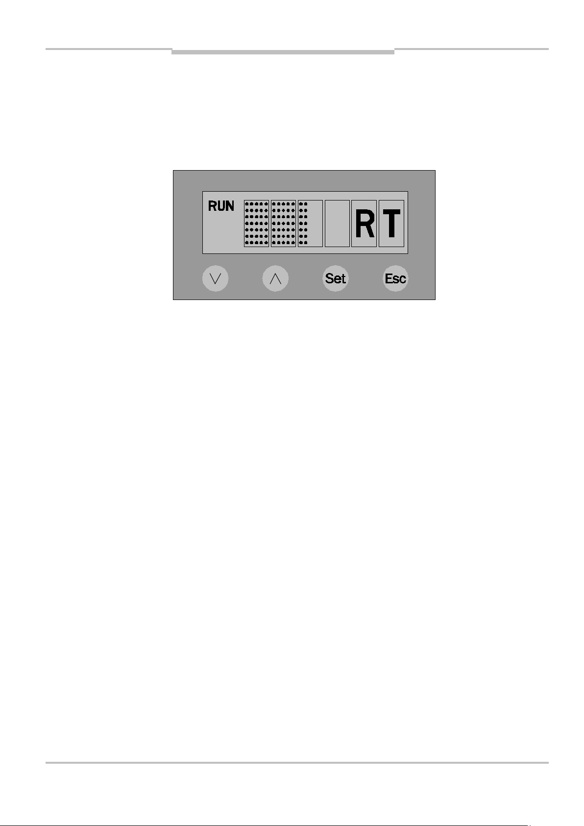
Bedienfeld mit LCD
-
Anzeige
Abb. 7:
kation
Betriebsanleitung
ISD400
4.1 Menüebene 1 PROFIBUS
Display im
Run-Mode
bei aktiver
Kommuni-
8012620/YYZ3/2016-08-01 © SICK AG • Deutschland • Alle Rechte vorbehalten 25
Page 26
Bedienfeld mit LCD
-
Anzeige
Betriebsanleitung
ISD400
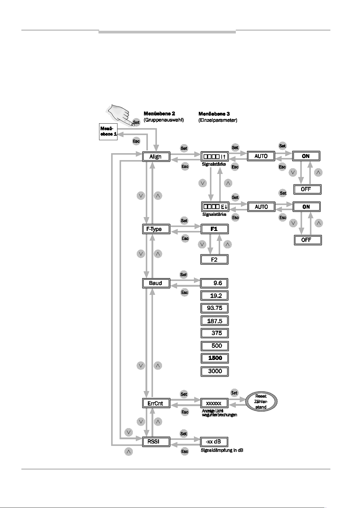
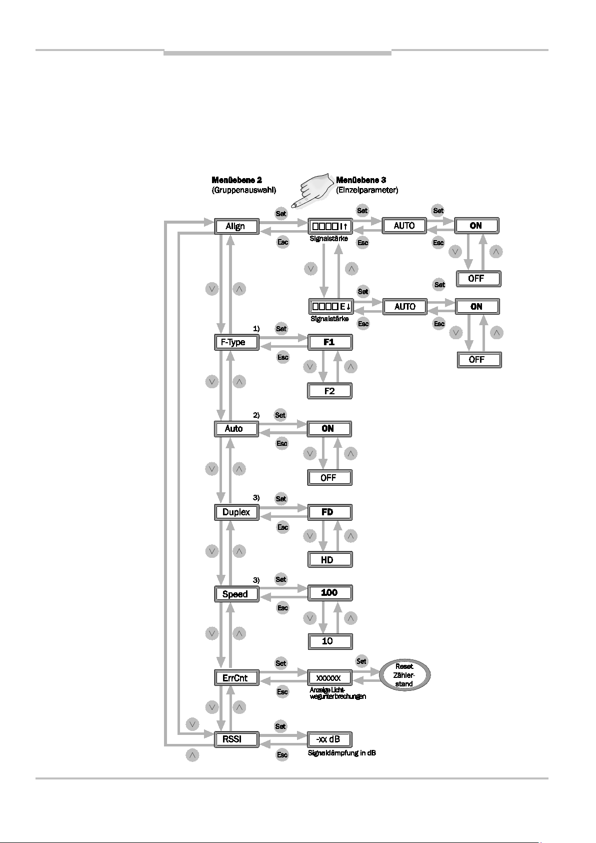
4.2 Menüebene 2 bzw. 3 PROFIBUS
26 © SICK AG • Deutschland • Alle Rechte vorbehalten 8012620/YYZ3/2016-08-01
Page 27

Bedienfeld mit LCD
-
Anzeige
Anzeige
Gegenseite (E ↓)
Schaltet die
Ausrichtmodus aus.
Tab. 2:
PROFIBUS
Betriebsanleitung
ISD400
4.3 Parameterliste PROFIBUS
Parameterliste
Bezeichnung
Auswahl
Align I, E
Auto On, Off
Funktion
Empfangspegel
eigene Seite (I ↑),
automatische
Umstellung der
Gegenstelle in den
F-Type F1, F2 Auswahl Trägerfre-
quenz F1 bzw. F2
Baud 9.6 …
3000
Übertragungsrate
in kbit/s
8012620/YYZ3/2016-08-01 © SICK AG • Deutschland • Alle Rechte vorbehalten 27
Page 28

Bedienfeld mit LCD
-
Anzeige
Betriebsanleitung
ISD400
Bezeich-
Auswahl
Funktion
nung
ErrCnt – Zähler für Lichtweg-
unterbrechung
(Reset mit SET)
RSSI – Signaldämpfung
in dB
28 © SICK AG • Deutschland • Alle Rechte vorbehalten 8012620/YYZ3/2016-08-01
Page 29

Bedienfeld mit LCD
-
Anzeige
Abb. 8:
Ethernet
Betriebsanleitung
ISD400
4.4 Menüebene 1 Ethernet
Menüebene 1
4.4.1 Ethernet-Busstatus
Der Ethernet-Busstatus wird durch
das RUN-Icon signalisiert:
RUN statisch ein:
Ethernet-Link OK
RUN blinkend:
Ethernet-Link OK, geräteinterner
Datenpuffer (8 kB) voll, Tele-
8012620/YYZ3/2016-08-01 © SICK AG • Deutschland • Alle Rechte vorbehalten 29
gramme werden verworfen
RUN aus:
Ethernet-Link nicht vorhanden
Page 30
Bedienfeld mit LCD
-
Anzeige
Abb. 9:
Ethernet
Betriebsanleitung
ISD400
4.5 Menüebene 2 bzw. 3 Ethernet
Menüebene 2
30 © SICK AG • Deutschland • Alle Rechte vorbehalten 8012620/YYZ3/2016-08-01
Page 31

Bedienfeld mit LCD
-
Anzeige
Betriebsanleitung
ISD400
1)
Beim Eintritt in den Menüpunkt wird die
aktuell gültige Frequenz zuerst angezeigt.
2)
Beim Eintritt in den Menüpunkt wird die
aktuell gültige Einstellung zuerst gezeigt.
3)
Beim Eintritt in den Menüpunkt wird die
aktuell gültige Einstellung zuerst angezeigt. Steht Auto auf ON, wird die automatisch gewählte Konfiguration angezeigt;
eine Änderung ist dann nicht möglich.
8012620/YYZ3/2016-08-01 © SICK AG • Deutschland • Alle Rechte vorbehalten 31
Page 32

Bedienfeld mit LCD
-
Anzeige
Anzeige Empfangs-
(E ↓)
Tab. 3:
Ethernet
Betriebsanleitung
ISD400
4.6 Parametrierliste Ethernet
Parameterliste
Bezeichnung
Auswahl
Align I, E
AUTO ON,
OFF
Funktion
pegel eigene Seite
(I ↑), Gegenseite
Schaltet die
automatische Umstellung der Gegen-
F-Type F1, F2 Auswahl Trägerfre-
32 © SICK AG • Deutschland • Alle Rechte vorbehalten 8012620/YYZ3/2016-08-01
stelle in den Ausrichtmodus aus.
quenz F1 bzw. F2
Page 33

Bedienfeld mit LCD
-
Anzeige
Betriebsanleitung
ISD400
Bezeichnung
Auswahl
Auto ON,
OFF
Funktion
Auswahl Autonegotiation aktiv
bzw. inaktiv
Hinweis: Wenn
„Auto“ = „ON“,
zeigen die
Duplex FD,
HD
Parameter "Duplex"
und "Speed" die
automatisch
ermittelten
Parameter an.
Auswahl Datenfluss
Vollduplex bzw.
Halbduplex
8012620/YYZ3/2016-08-01 © SICK AG • Deutschland • Alle Rechte vorbehalten 33
Page 34

Bedienfeld mit LCD
-
Anzeige
Betriebsanleitung
ISD400
Bezeich-
Auswahl
Funktion
nung
Speed 100,
10
Auswahl Datenrate
100 Mbit/s bzw.
10 Mbit/s
ErrCnt – Zähler für Lichtweg-
unterbrechung
(Reset mit SET)
RSSI – Signaldämpfung
in dB
34 © SICK AG • Deutschland • Alle Rechte vorbehalten 8012620/YYZ3/2016-08-01
Page 35

Betriebsanleitung
Inbetriebnahme
ISD400
5 Inbetriebnahme
5.1 Gerätekonfiguration
Hinweis
Vor Inbetriebnahme ist die
Frequenz F1/F2 zu wählen. Die
Baudrate (für PROFIBUS) ist an die
Baudrate des Busmasters anzupassen (default: 1500 Mbit/s). Bei
Ethernet ist defaultmäßig Autonegotiation eingestellt.
8012620/YYZ3/2016-08-01 © SICK AG • Deutschland • Alle Rechte vorbehalten 35
Page 36

Betriebsanleitung
Inbetriebnahme
ISD400
5.2 Bus-Terminierung bei PROFIBUS
Endet das PROFIBUS-Kabel an
der ISD400 (kein Buskabel an
Buchse „PROFIBUS out“), ist der
Bus mittels eines Terminierungssteckers in der Buchse
„PROFIBUS out“ abzuschließen.
5.3 Ausrichtung
Üblicherweise stehen sich die Geräte zunächst in der Nahdistanz
gegenüber. Nach Anlegen der
Versorgungsspannung geht das
36 © SICK AG • Deutschland • Alle Rechte vorbehalten 8012620/YYZ3/2016-08-01
ISD400 automatisch in den RUNMode über. Besteht die optische
Verbindung zum gegenüberliegenden Gerät, wird dies durch die
Page 37

Betriebsanleitung
Inbetriebnahme
ISD400
orange Status-LED signalisiert (permanent aktiv) und es können sofort
Daten übertragen werden.
Fahren Sie mit dem Fahrzeug so
weit, bis die Datenübertragung
des ISD400 abbricht und die
orange Status-LED blinkt. Die Geräte können jetzt jeweils einzeln
nachjustiert werden. Bei zu geringem Empfangspegel muss der
gegenüberliegende Sender nachjustiert werden. Im Run-Mode ist
die Güte der Ausrichtung des
Senders direkt am Bargraph des
Empfängers ablesbar. Für eine
komfortable Ausrichtung des
8012620/YYZ3/2016-08-01 © SICK AG • Deutschland • Alle Rechte vorbehalten 37
Senders kann an diesem der
ALIGN-Mode aktiviert werden.
Page 38

Betriebsanleitung
Inbetriebnahme
ISD400
In der Werkseinstellung
"Align"/"AUTO" = "ON" ist danach
sowohl der Empfangspegel des
gegenüberliegenden Empfängers
(E ↓) als auch des eigenen
Empfängers (I ↑) ohne Wechsel
des Standorts ablesbar. Bei guter
Ausrichtung müssen die StatusLEDs beider ISD400 aktiv sein.
Zur Weiterfahrt ist in den RUN-
Mode zu wechseln und gegebenenfalls die Nachjustierung zu
wiederholen.
Die optische Ausrichthilfe mit Fadenkreuz erleichtert die Ausrichtung
zusätzlich.
38 © SICK AG • Deutschland • Alle Rechte vorbehalten 8012620/YYZ3/2016-08-01
Nehmen Sie im Nahbereich die
Ausrichtung ggfs. mit einem
geraden mechanischen Hilfsmittel
wie z. B. einer langen Wasserwaage
Page 39

Betriebsanleitung
Inbetriebnahme
ISD400
vor, falls die gegenüberliegende ISD
über die optische Ausrichthilfe nicht
deutlich genug erkennbar sein
sollte.
Hinweis
Im ALIGN-Mode ist keine Buskommunikation möglich.
Nach der Inbetriebnahme wird
empfohlen den Parameter
"Align"/"AUTO" auf "OFF" zu
parametrieren. Damit ist gewährleistet, dass bei Kommunikationsstörungen kein automatischer
Sprung in den ALIGN-Mode erfolgt.
8012620/YYZ3/2016-08-01 © SICK AG • Deutschland • Alle Rechte vorbehalten 39
Page 40

Betriebsanleitung
Inbetriebnahme
ISD400
5.4 Sende-LED über MFEingang ausschalten
Über den MF-Eingang kann die
Sende-LED ausgeschaltet werden.
Im ausgeschalteten Zustand blinkt
die orange Status-LED und im
Display wird "LsrOff" angezeigt.
5.5 Anzeige orange Status-LED
Die orange Status-LED gibt
Aufschluss über den Betriebsstatus
40 © SICK AG • Deutschland • Alle Rechte vorbehalten 8012620/YYZ3/2016-08-01
der ISD400.
Folgende Betriebsstati und Geräte-
verhalten werden angezeigt:
Page 41

Betriebsanleitung
Inbetriebnahme
ISD400
Im RUN-Modus:
genügend Pegel
-> LED dauerhaft ein
Pegel fällt unter Warnschwelle
-> LED blinkt, Kommunikation
weiter möglich
Pegel fällt unter Funktionsschwelle
-> LED blinkt, Kommunikation nicht
mehr möglich
Im ALIGN-Modus:
genügend Pegel
-> LED dauerhaft ein
Pegel fällt unter Warnschwelle
-> LED blinkt
Pegel fällt unter Funktionsschwelle
8012620/YYZ3/2016-08-01 © SICK AG • Deutschland • Alle Rechte vorbehalten 41
-> LED dauerhaft aus
Page 42

Betriebsanleitung
Technische Daten
Tab. 4:
ISD400
ISD400
6 Technische Daten
6.1 Datenblatt
Allgemeine Daten
Datenblatt
Betriebs-
0,2 … 180 m
reichweite
Lichtquelle Infrarot-LED,
850 nm
Öffnungs-
± 0,5°
winkel
Lichtfleck-
durchmesser
1,75 m bei 100 m
Entfernung
42 © SICK AG • Deutschland • Alle Rechte vorbehalten 8012620/YYZ3/2016-08-01
Page 43

Betriebsanleitung
Technische Daten
ISD400
Elektrische Daten
Versorgungs-
DC 18 … 30 V
spannung UV
Strom-
aufnahme
Ohne Heizung max.
0,4 A
Mit Heizung max.
1,2 A
Schutzklasse
Anschluss Stecker M12
Anzeigen/Bedienelemente
Optische
Fadenkreuz
Ausrichthilfe
Status-LED Funktionsanzeige
und Pegelwarnung
(orange)
LCD-Anzeige Balkenanzeige für
Empfangspegel,
8012620/YYZ3/2016-08-01 © SICK AG • Deutschland • Alle Rechte vorbehalten 43
Menüführung
Page 44

Betriebsanleitung
Technische Daten
ISD400
Bedienung 4 Folientasten,
Menüführung
Ausrichtmodus
Schnittstellen Daten-
Wählbare Anzeige
des internen und
externen Empfangspegels über Balkenanzeige
PROFIBUS
schnittstelle
Ethernet
Baudrate
PROFIBUS
9,6, 19,2, 93,75,
187,5, 375, 500,
1500, 3000 kBit/s,
einstellbar über
Bedientasten
Ethernet 10/100 Mbit/s
44 © SICK AG • Deutschland • Alle Rechte vorbehalten 8012620/YYZ3/2016-08-01
Page 45

Betriebsanleitung
Technische Daten
ISD400
Signalverzögerung
PROFIBUS
Signalverzögerung
Ethernet
Schalteingang MF
1 µs + 2 Tbit
≤ 350 µs + Anzahl
der Bytes x 8 /
3 Mbit/s
UV – 2 V: Sende-LED
deaktiviert
Schaltausgang Q
PNP, UV – 2 V:
störungsfreier
Betrieb,
= 100 mA,
I
out
kurzschlussfest
Mechanische Daten
Gehäuse-
Metall
material
8012620/YYZ3/2016-08-01 © SICK AG • Deutschland • Alle Rechte vorbehalten 45
Gewicht Ca. 900 g
Page 46

Betriebsanleitung
Technische Daten
ISD400
Abmes-
60 x 105 x 105 mm
sungen
Schutzart IP 65
Umweltbedingungen
Umgebungs-
–25 … +55 °C
temperatur
–40 … +55 °C
(mit Heizung)
Lager-
–40 … +75 °C
temperatur
EMV1) EN 61000-6-2,
EN 61000-6-4
46 © SICK AG • Deutschland • Alle Rechte vorbehalten 8012620/YYZ3/2016-08-01
1)
Dies ist eine Einrichtung der Klasse A.
Diese Einrichtung kann im Wohnbereich
Funkstörungen verursachen.
Page 47

Betriebsanleitung
Technische Daten
Abb. 10:
ISD400
ISD400
6.2 Maßbilder
Maßbild
8012620/YYZ3/2016-08-01 © SICK AG • Deutschland • Alle Rechte vorbehalten 47
Page 48

Betriebsanleitung
Technische Daten
ISD400
6.3 Zubehör
6.3.1 Anschlusstechnik für PROFIBUS-Schnittstelle
PROFIBUS-Abschlusswiderstand
Typ Bestell-Nr.
PR-STE-END 6021156
48 © SICK AG • Deutschland • Alle Rechte vorbehalten 8012620/YYZ3/2016-08-01
Page 49

Betriebsanleitung
Technische Daten
ISD400
PROFIBUS-Leitungsdose, M12,
5-polig, Bus in
Typ Bestell-Nr.
PR-DOS-1205-G 6021353
PROFIBUS-Leitungsstecker, M12,
5-polig, Bus out
Typ Bestell-Nr.
PR-STE-1205-G 6021354
8012620/YYZ3/2016-08-01 © SICK AG • Deutschland • Alle Rechte vorbehalten 49
Page 50

Betriebsanleitung
Technische Daten
ISD400
PROFIBUS-Leitung, 2 x 0,34 mm2,
Meterware
Typ Bestell-Nr.
LTG-2102-MW 6021355
Temperatur-
bereich
Bewegt:
–5 … +80 °C
Festverlegt:
–40 … +80 °C
Mantel PUR violett
Ø 8 mm
Schirmung AL-PT-Folie
50 © SICK AG • Deutschland • Alle Rechte vorbehalten 8012620/YYZ3/2016-08-01
Page 51

Betriebsanleitung
Technische Daten
ISD400
Leitungsdose mit PROFIBUSLeitung, Bus in
Typ Bestell-Nr. Leitungslänge
DOL-12PR-G05
DOL-12PR-G10
6026006 5 m
6026008 10 m
8012620/YYZ3/2016-08-01 © SICK AG • Deutschland • Alle Rechte vorbehalten 51
Page 52

Betriebsanleitung
Technische Daten
ISD400
Leitungsstecker mit PROFIBUSLeitung, Bus in
Typ Bestell-Nr. Leitungslänge
STL-12PR-G05
STL-12PR-G10
6026005 5 m
6026007 10 m
52 © SICK AG • Deutschland • Alle Rechte vorbehalten 8012620/YYZ3/2016-08-01
Page 53

Betriebsanleitung
Technische Daten
ISD400
Ethernet Leitung M12 Stecker
D-codiert gerade auf RJ45 gerade
Typ Bestell-Nr. Leitungs-
länge
SSL-2J04G03ME
SSL-2J04G05ME
SSL-2J04G10ME
SSL-2J04G25ME
6029630 3 m
6035389 5 m
6030928 10 m
6033555 25 m
8012620/YYZ3/2016-08-01 © SICK AG • Deutschland • Alle Rechte vorbehalten 53
Page 54

Betriebsanleitung
Technische Daten
ISD400
PROFINET Leitung M12 Stecker Dcodiert gerade auf RJ45 gerade
Typ Bestell-Nr. Leitungs-
länge
SSL-2J04G02MZ60
SSL-2J04G05MZ60
SSL-2J04G10MZ60
6048244 3 m
6048245 5 m
6048246 10 m
54 © SICK AG • Deutschland • Alle Rechte vorbehalten 8012620/YYZ3/2016-08-01
Page 55

Betriebsanleitung
Technische Daten
ISD400
6.3.2 Ausrichtzubehör
Ausrichthalterung
Typ Bestell-Nr.
BEF-DME/ISD 2046052
8012620/YYZ3/2016-08-01 © SICK AG • Deutschland • Alle Rechte vorbehalten 55
Page 56

Betriebsanleitung
Technische Daten
ISD400
Befestigungswinkel
Typ Bestell-Nr.
BEF-WINKDME/ISD
2046444
56 © SICK AG • Deutschland • Alle Rechte vorbehalten 8012620/YYZ3/2016-08-01
Page 57

Betriebsanleitung
Technische Daten
ISD400
8012620/YYZ3/2016-08-01 © SICK AG • Deutschland • Alle Rechte vorbehalten 57
Page 58

Betriebsanleitung
Troubleshooting
F1/F2 wählen
Ausrichten
Baudrate
ISD400
7 Troubleshooting
Problem Ursache Lösung
NoSync (im
Display) bzw.
Status-LED
blinken
NoSync (im
Display) bzw.
Status-LED
blinken
F1/F2 nicht
gewählt
Kein
Sichtkontakt
NoSync (im
Display) bzw.
Status-LED
blinken
Kein R
(im Display)
58 © SICK AG • Deutschland • Alle Rechte vorbehalten 8012620/YYZ3/2016-08-01
Baudrate
nicht korrekt
Kein Telegramm von
Kupferseite
wählen
Verkabelung
prüfen
Page 59

Betriebsanleitung
Troubleshooting
ISD400
Problem Ursache Lösung
Kein T
(im Display)
Kein Telegramm von
optischer Seite
Status-LED aus Versorgung
fehlt/Hardware
defekt
Status-LED
blinkt
Funktionsreserve
Verkabelung
prüfen
Versorgung
überprüfen/
Gerät austauschen
Ausrichtung
überprüfen
Kein RUN-Icon
(im Display)
RUN-Icon (im
Display) blinkt
Kein EthernetLink vorhanden
Verkabelung
prüfen, BusParameter
prüfen
Pufferüberlauf Übertragene
Datenmenge
reduzieren
8012620/YYZ3/2016-08-01 © SICK AG • Deutschland • Alle Rechte vorbehalten 59
Page 60

Betriebsanleitung
Troubleshooting
ISD400
Problem Ursache Lösung
Keine
Datenübertragung
vorhanden,
SET-Icon im
Display aktiv
Schlechte
Ausrichtung;
Gerät ist im
Align-Modus
Nach
Inbetriebnahme den
Parameter
„Align“
„AUTO“ auf
„OFF“ setzen.
60 © SICK AG • Deutschland • Alle Rechte vorbehalten 8012620/YYZ3/2016-08-01
Page 61

Betriebsanleitung
Troubleshooting
ISD400
This work is protected by copyright. All rights
reserved by SICK AG. Reproduction of this
document or parts of this document is only
permissible within the limits of the legal
determination of Copyright Law. Modification
or expurgation of this work is prohibited
without the express written permission of
SICK AG.
8012620/YYZ3/2016-08-01 © SICK AG • Deutschland • Alle Rechte vorbehalten 61
Page 62

Betriebsanleitung
Contents
ISD400
Contents
1 About this document ........... 65
1.1 Purpose of this
document ...................... 65
1.2 Symbols used ................ 66
2 Product description ............. 68
2.1 Safety notes .................. 69
2.1.1 Safety standard ......... 69
2.1.2 Correct use ................. 69
2.2 Device name ................. 71
2.3 Principle of operation ... 73
2.4 Supported protocols ..... 74
2.5 Signal delay ................... 75
3 Mounting .............................. 76
3.1 Mutual interference ...... 76
3.2 Mechanical mounting ... 78
3.3 Cascading of multiple
transmission lines ......... 80
3.4 Electrical connection .... 81
62 © SICK AG • Deutschland • Alle Rechte vorbehalten 8012620/YYZ3/2016-08-01
Page 63

Betriebsanleitung
Contents
ISD400
4 Control panel with LCD
display .................................. 83
4.1 Menu level 1
(PROFIBUS) .................... 84
4.2 Menu levels 2 and 3
PROFIBUS ...................... 85
4.3 Parameter list
PROFIBUS ...................... 86
4.4 Menu level 1 Ethernet .. 88
4.4.1 Ethernet bus status ... 88
4.5 Menu level 2 or 3
Ethernet ......................... 89
5 Commissioning .................... 94
5.1 Device configuration ..... 94
5.2 Bus termination with
PROFIBUS ...................... 95
5.3 Alignment ...................... 95
5.4 Switch OFF Send LED
via MF input ................... 99
8012620/YYZ3/2016-08-01 © SICK AG • Deutschland • Alle Rechte vorbehalten 63
5.5 Display of the orange
status LED ..................... 99
Page 64

Betriebsanleitung
Contents
ISD400
6 Technical data ................... 101
6.1 Data sheet ................... 101
6.2 Dimensional drawings 106
6.3 Accessories ................. 107
6.3.1 Connectivity for
PROFIBUS interface 107
6.3.2 Alignment
accessories .............. 114
7 Troubleshooting ................. 117
64 © SICK AG • Deutschland • Alle Rechte vorbehalten 8012620/YYZ3/2016-08-01
Page 65

Betriebsanleitung Kapitel 1
About this document
ISD400
1 About this document
Please read this chapter carefully
before you begin working with this
documentation and the ISD400.
1.1 Purpose of this document
These operating instructions are for
giving technical personnel of the
machine manufacturer or operator
instructions on the safe mounting,
configuration, electrical installation,
commissioning, operation and
maintenance of the ISD400 optical
data transmission system.
These operating instructions do not
provide information on operating
the machine in which the optical
8012620/YYZ3/2016-08-01 © SICK AG • Deutschland • Alle Rechte vorbehalten 65
Page 66

Kapitel 1 Betriebsanleitung
About this document
ISD400
data transmission system is
integrated. For information about
this, refer to the instruction manual
of the respective machine.
1.2 Symbols used
Note
Take
action …
Notes inform you about special
aspects of the device.
Instructions for taking action are
indicated by an arrow. Read
carefully and follow the instructions
for action.
66 © SICK AG • Deutschland • Alle Rechte vorbehalten 8012620/YYZ3/2016-08-01
Page 67

Betriebsanleitung Kapitel 1
About this document
WARNING
ISD400
Warning!
A warning indicates a specific or
potential hazard. This is intended to
protect you against accidents.
Read carefully and follow the
warnings!
8012620/YYZ3/2016-08-01 © SICK AG • Deutschland • Alle Rechte vorbehalten 67
Page 68

Kapitel 2 Betriebsanleitung
Product description
ISD400
2 Product description
This chapter provides information
on the special properties of the
ISD400. It describes the
construction and operating principle
of the device, in particular the
various operating modes.
Always read this chapter before
you mount, install and
commission the device.
68 © SICK AG • Deutschland • Alle Rechte vorbehalten 8012620/YYZ3/2016-08-01
Page 69

Betriebsanleitung Kapitel 2
Product description
ISD400
2.1 Safety notes
2.1.1 Safety standard
The ISD400 optical data
transmission system has been
developed, produced and tested in
accordance with the applicable
safety standards. It is a state-of-theart device.
2.1.2 Correct use
The ISD400 optical data
transmission system has been
designed and developed for optical
transmission of data using infrared
light.
8012620/YYZ3/2016-08-01 © SICK AG • Deutschland • Alle Rechte vorbehalten 69
Page 70

Kapitel 2 Betriebsanleitung
Product description
WARNING
ISD400
The protection of personnel and the
Note
device cannot be guaranteed if the
device is operated in a manner not
corresponding to its correct use.
Faultless operation requires an
uninterrupted safety contact
between the two ISD400. Should
safety contact interruptions arise in
the application (e.g., in the event of
maintenance work), we recommend
first switching off the sender LEDs
of the two ISD400 via the MF input.
This prevents communication faults.
70 © SICK AG • Deutschland • Alle Rechte vorbehalten 8012620/YYZ3/2016-08-01
Page 71

Betriebsanleitung Kapitel 2
Product description
Tab. 5:
designation
ISD400
Areas of application
The ISD400 is suitable for the
following areas of application:
Automated high-bay warehouses
Stationary data transmission
between buildings
Anywhere, where data
transmission to and from
stationary or moving objects
(visual contact) over relatively
long distances (up to 180 m) is
required.
2.2 Device name
Data
Device
Order No. Heating
Device
8012620/YYZ3/2016-08-01 © SICK AG • Deutschland • Alle Rechte vorbehalten 71
interface
name
PROFIBUS ISD400-
1111
1042286 without
Page 72

Kapitel 2 Betriebsanleitung
Product description
ISD400
Data
interface
Device
name
ISD4001121
Ethernet ISD400-
6111
ISD4006121
Order No. Heating
1043511 with
1046119 without
1046120 with
72 © SICK AG • Deutschland • Alle Rechte vorbehalten 8012620/YYZ3/2016-08-01
Page 73

Betriebsanleitung Kapitel 2
Product description
Fig. 11:
operation
ISD400
2.3 Principle of operation
To prevent mutual interference
when operating in duplex mode, the
data transmission system use two
Principle of
different frequency pairs. These are
set via the control panel.
Both devices monitor the received
signal level which can be displayed
on a bar graph indicator. If the
received level drops below a certain
level e.g. due to soiling of the optics,
8012620/YYZ3/2016-08-01 © SICK AG • Deutschland • Alle Rechte vorbehalten 73
a warning output signal is activated.
All work on the device (mounting,
connecting, aligning, configuration)
Page 74

Kapitel 2 Betriebsanleitung
Product description
ISD400
can be performed from the top of
the units.
2.4 Supported protocols
The ISD400 supports the following
data protocols:
Note
PROFIBUS:
PROFIBUS, MPI and PROFIsafe can
be transmitted.
Ethernet:
EtherNet TCP/IP, EtherNet/IP,
PROFINET and PROFIsafe can be
transmitted.
When transmitting Ethernet
protocols, the maximum optical
data transmission rate of 3 Mbit/s,
as well as the maximum input and
output data buffer of 8 kByte of the
74 © SICK AG • Deutschland • Alle Rechte vorbehalten 8012620/YYZ3/2016-08-01
Page 75

Betriebsanleitung Kapitel 2
Product description
ISD400
ISD400 should be taken into
account.
To reduce data traffic, external
switches or routers can be used.
2.5 Signal delay
The signal delays documented in
the appendix "Technical data" may
require in borderline cases
adjustment of the bus timing
parameters in the control.
8012620/YYZ3/2016-08-01 © SICK AG • Deutschland • Alle Rechte vorbehalten 75
Page 76

Kapitel 3 Betriebsanleitung
Mounting
ISD400
3 Mounting
This chapter describes how to
prepare and mount the ISD400
optical data transmission system.
The devices can be mounted
horizontally or vertically on the
bracket.
3.1 Mutual interference
Operation of two optical data
transmission devices side by side is
required in some applications. A
minimum distance between the
devices must be maintained.
76 © SICK AG • Deutschland • Alle Rechte vorbehalten 8012620/YYZ3/2016-08-01
Page 77

Betriebsanleitung Kapitel 3
Mounting
Fig. 12:
Distances
ISD400
d
d
s
= s
min
= Minimum distance
min
= Max. required scanning range
max
max
x tan (0.5°)
8012620/YYZ3/2016-08-01 © SICK AG • Deutschland • Alle Rechte vorbehalten 77
When the ISD400 optical data
transmission device is mounted in
parallel to a DME distance sensor or
DL100 product family, a minimum
distance of 100 mm must be
Page 78

Kapitel 3 Betriebsanleitung
Mounting
ISD400
maintained (a >100 mm). This
minimum distance is independent
of the maximum distance between
the two ISDs.
3.2 Mechanical mounting
Install the devices so the optical
axes of the two devices match at
minimum distance:
– Line distance 0.2 to 180 m:
Install the two devices facing
one another but rotate one
through 180°.
– Line distance 3.0 to 180 m:
The two devices can be
78 © SICK AG • Deutschland • Alle Rechte vorbehalten 8012620/YYZ3/2016-08-01
installed without 180° rotation.
Page 79

Betriebsanleitung Kapitel 3
Mounting
Fig. 13:
installation
ISD400
ISD400
horizontal
and vertical
Receiver
Sender
Status LED (function indicator /
level warning)
Optical alignment aid
(crosshair)
8012620/YYZ3/2016-08-01 © SICK AG • Deutschland • Alle Rechte vorbehalten 79
Page 80

Kapitel 3 Betriebsanleitung
Mounting
ISD400
3.3 Cascading of multiple transmission lines
Up to 2 transmission lines can be
connected in series (cascaded).
80 © SICK AG • Deutschland • Alle Rechte vorbehalten 8012620/YYZ3/2016-08-01
Page 81

Betriebsanleitung Kapitel 3
Mounting
ISD400
3.4 Electrical connection
Fig. 14:
Connection
type,
PROFIBUS
5-pin, 5-pin, 4-pin,
M12, M12, M12
Bus in Bus out
8012620/YYZ3/2016-08-01 © SICK AG • Deutschland • Alle Rechte vorbehalten 81
Page 82

Kapitel 3 Betriebsanleitung
Mounting
ISD400
Fig. 15:
Connection
type,
Ethernet
4-pin, 4-pin,
M12, M12
Ethernet
82 © SICK AG • Deutschland • Alle Rechte vorbehalten 8012620/YYZ3/2016-08-01
Page 83

Betriebsanleitung Kapitel 4
Control panel with LCD display
Fig. 16:
panel
ISD400
4 Control panel with
LCD display
6 segments with 5x7 pixels
Level indicator with max. 20 bars
(4 segments with 7 pixels per bar)
Control
Mode indicators with: RUN, SET,
MEN
4 buttons DOWN, UP, SET, ESC
8012620/YYZ3/2016-08-01 © SICK AG • Deutschland • Alle Rechte vorbehalten 83
Page 84

Kapitel 4 Betriebsanleitung
Control panel with LCD
display
Fig. 17:
tion
ISD400
4.1 Menu level 1 (PROFIBUS)
Display in
Run mode
during
active
communica
84 © SICK AG • Deutschland • Alle Rechte vorbehalten 8012620/YYZ3/2016-08-01
Page 85

Betriebsanleitung Kapitel 4
Control panel with LCD
display
ISD400
4.2 Menu levels 2 and 3 PROFIBUS
8012620/YYZ3/2016-08-01 © SICK AG • Deutschland • Alle Rechte vorbehalten 85
Page 86

Kapitel 4 Betriebsanleitung
Control panel with LCD
display
Display of
(E ↓)
Switches off
Align mode.
Tab. 6:
PROFIBUS
ISD400
4.3 Parameter list PROFIBUS
Name Selection Function
Parameter
list,
Align I, E
reception level
own side (I ↑),
opposite side
Auto On, Off
automatic
changeover of the
remote station to
F-Type F1, F2 Selection of
Baud 9.6 to
86 © SICK AG • Deutschland • Alle Rechte vorbehalten 8012620/YYZ3/2016-08-01
3000
carrier frequency
F1 or F2
Transmission rate
in kbit/s
Page 87

Betriebsanleitung Kapitel 4
Control panel with LCD
display
ISD400
Name Selection Function
ErrCnt – Counter for light
beam interruption
(reset with SET)
RSSI – Signal damping
in dB
8012620/YYZ3/2016-08-01 © SICK AG • Deutschland • Alle Rechte vorbehalten 87
Page 88

Kapitel 4 Betriebsanleitung
Control panel with LCD
display
Fig. 18:
1 Ethernet
ISD400
4.4 Menu level 1 Ethernet
Menu level
4.4.1 Ethernet bus status
The Ethernet bus status is indicated
by the RUN icon:
RUN static on:
Ethernet link OK
RUN flashing:
Ethernet link OK, device-internal
data buffer (8 kB) full, telegrams
are discarded
RUN off:
No Ethernet link
88 © SICK AG • Deutschland • Alle Rechte vorbehalten 8012620/YYZ3/2016-08-01
Page 89

Betriebsanleitung Kapitel 4
Control panel with LCD
display
Fig. 19:
2 Ethernet
ISD400
4.5 Menu level 2 or 3 Ethernet
Menu level
8012620/YYZ3/2016-08-01 © SICK AG • Deutschland • Alle Rechte vorbehalten 89
Page 90

Kapitel 4 Betriebsanleitung
Control panel with LCD
display
ISD400
4)
When you access the menu item, the
currently valid frequency is first
displayed.
5)
When you access the menu item, the
currently valid setting is first displayed.
6)
When you access the menu item, the
currently valid setting is first displayed. If
Auto is set to ON, the automatically
selected configuration is displayed; then
a change is not possible.
90 © SICK AG • Deutschland • Alle Rechte vorbehalten 8012620/YYZ3/2016-08-01
Page 91

Betriebsanleitung Kapitel 4
Control panel with LCD
display
Display of
(E ↓)
changeover of the
Tab. 7:
Ethernet
ISD400
4.6 Parameter list Ethernet
Name Selection Function
Parameter
list
Align I, E
reception level
own side (I ↑),
opposite side
AUTO ON, OFF Switches off
automatic
remote station to
Align mode.
F-Type F1, F2 Selection of
8012620/YYZ3/2016-08-01 © SICK AG • Deutschland • Alle Rechte vorbehalten 91
carrier frequency
F1 or F2
Page 92

Kapitel 4 Betriebsanleitung
Control panel with LCD
display
"ON", the "Duplex"
ISD400
Name Selection Function
Auto ON, OFF Selection of
autonegotiation
active or inactive
Note: If "Auto" =
and "Speed"
Duplex FD, HD Selection of data
Speed 100, 10 Selection of data
parameters
display the
automatically
determined
parameters.
flow full-duplex or
half-duplex
92 © SICK AG • Deutschland • Alle Rechte vorbehalten 8012620/YYZ3/2016-08-01
rate 100 Mbit/s
or 10 Mbit/s
Page 93

Betriebsanleitung Kapitel 4
Control panel with LCD
display
beam interruption
ISD400
Name Selection Function
ErrCnt – Counter for light
(reset with SET)
RSSI – Signal damping
in dB
8012620/YYZ3/2016-08-01 © SICK AG • Deutschland • Alle Rechte vorbehalten 93
Page 94

Kapitel 5 Betriebsanleitung
Commissioning
ISD400
5 Commissioning
5.1 Device configuration
Note
Before operating the devices, you
must select the frequency F1/F2.
Set the data transmission rate for
PROFIBUS to the same data
transmission rate as the bus master
(default: 1500 Mbit/s). For
Ethernet, the default is autonegotiation.
94 © SICK AG • Deutschland • Alle Rechte vorbehalten 8012620/YYZ3/2016-08-01
Page 95

Betriebsanleitung Kapitel 5
Commissioning
ISD400
5.2 Bus termination with PROFIBUS
If the PROFIBUS cable ends at
ISD400 (no bus cable at the
"PROFIBUS out" jack), terminate
the bus using a terminator plug in
the "PROFIBUS out" jack.
5.3 Alignment
The devices are normally first
aligned at a close distance. After
you connect the supply voltage, the
ISD400 switches into RUN mode
automatically. If there is an optical
8012620/YYZ3/2016-08-01 © SICK AG • Deutschland • Alle Rechte vorbehalten 95
connection to the opposing device,
this is indicated by the orange
status LED (permanently active) and
Page 96

Kapitel 5 Betriebsanleitung
Commissioning
ISD400
data can be transmitted
immediately.
Move the vehicle until the data
transmission of the ISD400 is
interrupted and the orange status
LED flashes. The devices can be
realigned individually one after
another. If there is a low reception
level, the opposing sender must
be realigned. In Run mode, the
quality of the alignment of the
sender can be read from the bar
graph of the receiver directly. For
convenient alignment of the
sender, ALIGN mode can be
activated on the sender.
96 © SICK AG • Deutschland • Alle Rechte vorbehalten 8012620/YYZ3/2016-08-01
Page 97

Betriebsanleitung Kapitel 5
Commissioning
ISD400
In the default setting "Align" /
"AUTO" = "ON", both the reception
level of the opposing receiver
(E ↓) and current receiver (I ↑)
can be read without a change of
location. If the alignment is good,
the status LEDs of both ISD400
devices must be active.
Switch to RUN mode to drive on
and repeat the realignment if
required.
The optical alignment aid with
crosshairs serves to further simplify
the alignment.
Use a straight mechanical aid if
necessary, e.g. a long bubble level,
in close proximity for alignment if
8012620/YYZ3/2016-08-01 © SICK AG • Deutschland • Alle Rechte vorbehalten 97
the opposing ISD cannot be seen
clearly enough via the optical
alignment aid.
Page 98

Kapitel 5 Betriebsanleitung
Commissioning
ISD400
Note
No bus communication is possible
in ALIGN mode.
After commissioning, it is
recommended that you set the
"Align" / "AUTO" parameter to "OFF".
This ensures that ALIGN mode does
not automatically start in the event
of communication faults.
98 © SICK AG • Deutschland • Alle Rechte vorbehalten 8012620/YYZ3/2016-08-01
Page 99

Betriebsanleitung Kapitel 5
Commissioning
ISD400
5.4 Switch OFF Send LED via MF input
The MF input can be used to switch
off the Send LED. When OFF, the
orange status LED flashes and
"LsrOff" appears on the display.
5.5 Display of the orange status LED
The orange status LED provides
information about the operating
status of the ISD400.
The following operating statuses
8012620/YYZ3/2016-08-01 © SICK AG • Deutschland • Alle Rechte vorbehalten 99
and device behaviors are displayed:
Page 100

Kapitel 5 Betriebsanleitung
Commissioning
ISD400
In RUN mode:
Sufficient level
-> LED ON continuously
Level falls below warning threshold
-> LED flashes, communication can
continue
Level falls below functional
threshold
-> LED flashes, communication no
longer possible
In ALIGN mode:
Sufficient level
-> LED ON continuously
Level falls below warning threshold
-> LED flashes
100 © SICK AG • Deutschland • Alle Rechte vorbehalten 8012620/YYZ3/2016-08-01
Level falls below functional
threshold
-> LED OFF continuously
 Loading...