

Page 1

IOLSHPB-P3104R01
Feldmodul für IO-Link Devices
Field module of IO-Link devices
BETRIEBSANLEITUNG/OPERATING INSTRUCTIONS
D
GB
Page 2

Betriebsanleitung
IOLSHPB-P3104R01
2 © SICK AG • Industrial Sensors • Deutschland • Irrtümer und Änderungen vorbehalten 2010-07-05
Dieses Werk ist urheberrechtlich geschützt. Die dadurch begründeten Rechte bleiben bei der Firma SICK AG. Eine
Vervielfältigung des Werkes oder von Teilen dieses Werkes ist nur in den Grenzen der gesetzlichen Bestimmungen des Urheberrechtsgesetzes zulässig. Eine Abänderung oder Kürzung des Werkes ist ohne ausdrückliche
schriftliche Zustimmung der Firma SICK AG untersagt.
Page 3

Betriebsanleitung
IOLSHPB-P3104R01
2010-07-05 © SICK AG • Industrial Sensors • Deutschland • Irrtümer und Änderungen vorbehalten 3
Inhalt
Inhalt
1 Zu diesem Dokument......................................................................................................4
1.1 Funktion dieses Dokuments.................................................................................4
1.2 Zielgruppe..............................................................................................................4
1.3 Informationstiefe...................................................................................................4
1.4 Verwendete Symbole und Abkürzungen..............................................................4
2 Zur Sicherheit..................................................................................................................5
2.1 Bestimmungsgemäße Verwendung.....................................................................5
2.2 Allgemeine Sicherheitshinweise und Schutzmaßnahmen .................................5
3 Funktionsbeschreibung..................................................................................................6
4 Anschlussbeispiel ...........................................................................................................7
4.1 Anschlusshinweise................................................................................................ 7
4.2 Konfigurationsdaten .............................................................................................7
5 Inbetriebnahme und Betrieb..........................................................................................8
5.1 Slave-Adresse........................................................................................................ 8
5.2 Konfiguration mit GSD (Geräte-Stammdaten-Datei)...........................................8
5.2.1 Allgemein.............................................................................................8
5.2.2 Minimalkonfiguration....................................................................... 10
5.2.3 Maximalkonfiguration ...................................................................... 10
5.2.4 Beispielkonfiguration....................................................................... 15
5.3 Bedeutung der Prozessdaten des IO-Link Master Status................................ 19
5.4 Objekte des Masters.......................................................................................... 19
5.5 IO-Link CALL........................................................................................................ 24
5.6 IO-Link-Kommunikation direkt über DP/V1 (mit Slot und Index) .................... 24
5.7 IO-Link-Kommunikation indirekt über DP/V0................................................... 25
5.7.1 Die azyklische Kommunkation über Prozessdaten (DP/V0) ......... 25
5.7.2 Mechanismus der Übertragung in den Prozessdaten.................... 25
5.7.3 Vorgehensweise bei der Übertragung............................................. 27
5.8 Die Parameter bei VC1 haben folgende Bedeutung:....................................... 28
5.8.1 Allgemein.......................................................................................... 28
5.8.2 Beispiel 1.......................................................................................... 29
5.8.3 Beispiel 2.......................................................................................... 30
6 Diagnose....................................................................................................................... 31
6.1 Lokale Diagnose und Statusanzeigen .............................................................. 31
6.2 Diagnosedaten über den PROFIBUS................................................................. 32
6.2.1 Block 1: PROFIBUS-Standard-Diagnose.......................................... 34
6.2.2 Block 2: Kennungsbezogene Diagnose.......................................... 35
6.2.3 Block 3: Status-PDU (Port-Status)................................................... 35
6.2.4 Block 4: Kanalbezogene Diagnose ................................................. 36
6.2.5 Block 5: Revisionsdiagnose............................................................. 36
6.2.6 Block 6: IO-Link-spezifische Diagnose............................................ 37
7 Technische Daten ........................................................................................................ 39
7.1 Maßzeichnung.................................................................................................... 39
7.2 Pin-Belegung des PROFIBUS ............................................................................. 40
7.3 Pin-Belegung der Spannungsversorgung ULS................................................... 41
7.4 Pin-Belegung der Ports ...................................................................................... 41
7.5 Spezifikationen................................................................................................... 42
Page 4

Kapitel 1 Betriebsanleitung
IOLSHPB-P3104R01
4 © SICK AG • Industrial Sensors • Deutschland • Irrtümer und Änderungen vorbehalten 2010-07-05
Zu diesem Dokument
1 Zu diesem Dokument
Bitte lesen Sie dieses Kapitel sorgfältig, bevor Sie mit der Dokumentation und dem
Feldmodul IOLSHPB-P3104R01 arbeiten.
1.1 Funktion dieses Dokuments
Diese Betriebsanleitung leitet das technische Personal des Maschinenherstellers bzw.
Maschinenbetreibers zur sicheren Montage, Parametrierung, Inbetriebnahme sowie zum
Betrieb und zur Prüfung des Feldmoduls IOLSHPB-P3104R01 an.
1.2 Zielgruppe
Diese Betriebsanleitung richtet sich an die Planer, Entwickler und Betreiber von Anlagen,
welche durch einen oder mehrere Feldmodule IOLSHPB-P3104R01 betrieben werden
sollen.
Sie richtet sich auch an Personen, die das Feldmodul IOLSHPB-P3104R01 in eine Anlage
integrieren, erstmals in Betrieb nehmen oder prüfen.
1.3 Informationstiefe
Diese Betriebsanleitung enthält Informationen über das Feldmodul IOLSHPB-P3104R01
zu folgenden Themen:
Inbetriebnahme,
Konfiguration,
IO-Link-Kommunikation,
Parametrierung,
Diagnose.
Darüber hinaus sind bei Planung und Einsatz von Feldmodulen technische Fachkenntnisse
notwendig, die nicht in diesem Dokument vermittelt werden.
Nutzen Sie auch die Homepage im Internet unter: http://www.sick.com
1.4 Verwendete Symbole und Abkürzungen
Hinweise erläutern Vorteile bestimmter Einstellungen und helfen, den optimalen Nutzen
aus dem Feldmodul IOLSHPB-P3104R01 zu ziehen.
Warnhinweise!
Ein Warnhinweis weist Sie auf konkrete oder potenzielle Gefahren hin. Dies soll Sie vor
Unfällen bewahren.
Lesen und befolgen Sie Warnhinweise sorgfältig!
Hinweis
Hinweis
a
ACHTUNG
Page 5

Betriebsanleitung Kapitel 2
IOLSHPB-P3104R01
2010-07-05 © SICK AG • Industrial Sensors • Deutschland • Irrtümer und Änderungen vorbehalten 5
Zur Sicherheit
2 Zur Sicherheit
2.1 Bestimmungsgemäße Verwendung
Das Feldmodul IOLSHPB-P3104R01 ist für dezentrale Automatisierungsaufgaben unter
rauen Umgebungsbedingungen konzipiert. Das Feldmodul IOLSHPB-P3104R01 erfüllt die
Schutzart IP 65 und IP 67. Mit dem Feldmodul IOLSHPB-P3104R01 wird der direkte
Anschluss von IO-Link-Sensoren und -Aktoren (IOLD) mit bis zu 32 Byte IN und 32 Byte OUT
ermöglicht (alle Telegrammtypen).
Bei jeder anderen Verwendung sowie bei Veränderungen an den Geräten – auch im
Rahmen von Montage und Installation – verfällt jeglicher Gewährleistungsanspruch gegenüber der SICK AG.
2.2 Allgemeine Sicherheitshinweise und
Schutzmaßnahmen
> Die Betriebsanleitung vor der Inbetriebnahme lesen.
> Anschluss, Montage und Einstellung nur durch Fachpersonal vornehmen.
> Das Feldmodul IOLSHPB-P3104R01 bei Inbetriebnahme vor Feuchte und
Verunreinigung schützen.
> Das Feldmodul IOLSHPB-P3104R01 ist kein Sicherheitsmodul gemäß EU-Maschinen-
richtlinie.
> Die nationalen Sicherheits- und Unfallverhütungsvorschriften beachten.
> Reparaturen dürfen nur vom Hersteller durchgeführt werden. Eingriffe und Änderungen
am Feldmodul IOLSHPB-P3104R01 sind unzulässig.
> Verdrahtungsarbeiten, Öffnen und Schließen von elektrischen Verbindungen nur im
spannungslosen Zustand durchführen.
Page 6

Kapitel 3 Betriebsanleitung
IOLSHPB-P3104R01
6 © SICK AG • Industrial Sensors • Deutschland • Irrtümer und Änderungen vorbehalten 2010-07-05
Funktionsbeschreibung
3 Funktionsbeschreibung
Das Feldmodul IOLSHPB-P3104R01 verfügt an jeder der 5-poligen M12-Buchsen für die
Ports 1 bis Port 4 über:
eine C/Q-Leitung X(n), PIN 4
eine Geräteversorgung L+/L-, PIN 1/Pin 3 und
eine Funktionserde FE.
Diese Belegung ist auch auf dem Feldmodul IOLSHPB-P3104R01 aufgedruckt.
Jeder Port (1 bis 4) verfügt über vier Betriebsarten, die über Parameter der GSD individuell
eingestellt werden können.
In der Betriebsart Digital Input wird der binäre Zustand der C/Q-Leitung der Ports in den
Prozessdaten angezeigt.
In der Betriebsart SCAN-Mode eines Ports wird zyklisch im Abstand von ca. einer Sekunde
an jedem Port versucht, die Kommunikation mit einem IO-Link-Device aufzubauen. War
der Kommunikationsaufbau erfolgreich, wechselt der Zustand der C/Q-Leitung dieses
Ports in den IO-Link-Modus und bleibt in diesem Zustand, bis die Kommunikation
unterbrochen wird.
Im COM-Modus werden die IO-Link-Prozessdaten in den Prozessdaten angezeigt. Nach
einem Kommunikationsabbruch, z. B. „Leitung defekt“ oder „M12-Stecker nicht gesteckt“,
wird zyklisch im Abstand von ca. einer Sekunde versucht, eine Kommunikation
aufzubauen.
In der Betriebsart Digital Output kann der Port als digitaler Ausgang betrieben werden.
In der Betriebsart SIO-IN mit IO-Link-Access ist es möglich, ein IOLD im Standard-Input-
Modus zu betreiben und azyklische Dienste auszutauschen ohne die Betriebsart zu
wechseln. Während des azyklischen Datenaustausches ist das SIO-Bit nicht gültig.
Es gibt drei verschiedene Möglichkeiten der azyklischen Kommunikation zwischen dem
Feldmodul IOLSHPB-P3104R01 und dem IOLD:
1. Indirekte Lese-/Schreibzugriffe auf die IOLD-Objekte über den standardisierten IO-Link
CALL (DP/V1), welcher mit PROFIBUS-I&M-Funktionen realisiert wird
(Funktionsbaustein vorhanden).
2. Direkte Lese-/Schreibzugriffe auf die IOLD-Objekte über DP/V1 (Funktionsbaustein
vorhanden).
3. Direkte Lese-/Schreibzugriffe auf die IOLD-Objekte über einen konfigurierbaren
Prozessdatenkanal über DP/V0.
Page 7
Betriebsanleitung Kapitel 4
IOLSHPB-P3104R01
2010-07-05 © SICK AG • Industrial Sensors • Deutschland • Irrtümer und Änderungen vorbehalten 7
Anschlussbeispiel
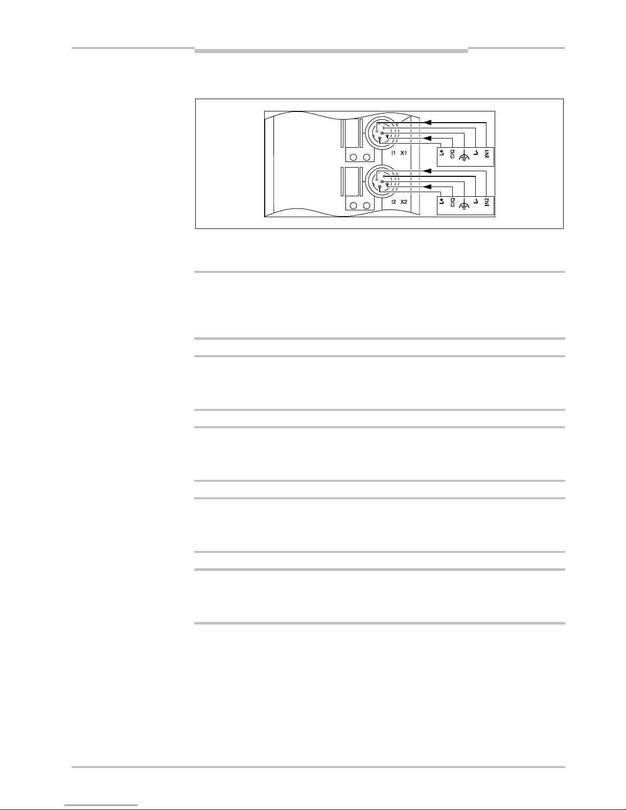
4 Anschlussbeispiel
4.1 Anschlusshinweise
Störfestigkeit erfüllen!
> Realisieren Sie den FE-Anschluss über eine Befestigungsschraube oder über eine
Kabelverbindung zur FE-Anschlusslasche (bei Montage auf einem nicht leitenden
Untergrund).
Schutzart garantieren!
> Versehen Sie nicht benutzte Anschlussbuchsen mit Schutzkappen, um die Schutzart
IP65/67 zu garantieren.
Schäden an der Elektronik vermeiden!
> Versorgen Sie die IO-Link-Devices ausschließlich mit der an den Anschlusspunkten
bereitgestellten Spannung U
S
.
Verpolungen vermeiden!
> Vermeiden Sie eine Verpolung der Versorgungsspannungen UL, US, um eine Beschädi-
gung des Geräts zu vermeiden.
Anschlusszuordnung beachten!
> Berücksichtigen Sie beim Anschluss der Sensoren die Zuordnung der Anschlüsse zu den
PROFIBUS-Eingangsprozessdaten (siehe Kapitel 7.2 „Pin-Belegung des PROFIBUS“).
4.2 Konfigurationsdaten
Identnummer: 0x0A8C
Eingabe-Adressraum: Abhängig von der Konfiguration
(minimal 2 Byte, maximal 162 Byte)
Ausgabe-Adressraum: Abhängig von der Konfiguration
(minimal 2 Byte, maximal 162 Byte)
A
bb. 1: Beispielhafter
Anschluss von IO-LinkDevices
a
ACHTUNG
a
ACHTUNG
a
ACHTUNG
a
ACHTUNG
a
ACHTUNG
Page 8

Kapitel 5 Betriebsanleitung
IOLSHPB-P3104R01
8 © SICK AG • Industrial Sensors • Deutschland • Irrtümer und Änderungen vorbehalten 2010-07-05
Inbetriebnahme und Betrieb
5 Inbetriebnahme und Betrieb
5.1 Slave-Adresse
Vor dem Einschalten des Feldmoduls IOLSHPB-P3104R01 muss eine gültige PROFIBUSSlave-Adresse eingestellt werden. Der Wertebereich muss zwischen „1“ und „126“ liegen.
1 ≤ Feldmodul-Adresse ≤ 126
> Stellen Sie mit den beiden Drehcodierschaltern X10 (für Zehnerstellen) und X1 (für
Einerstellen) die Stationsadresse ein, unter der das Gerät vom PROFIBUS-Master
angesprochen wird.
Bei Einschalten des Gerätes wird diese Adresse übernommen und kann im Betrieb nicht
mehr verändert werden.
5.2 Konfiguration mit GSD (Geräte-Stammdaten-Datei)
5.2.1 Allgemein
Die GSD „Sick0A8C.GSD“ enthält folgende Module:
Module der GSD IO-Link-
Betriebsart
Bedeutung Hinweis
IO-Link Master Status – Status des IOPLM (2 Byte)
digital IN – Slot/Port ist ein digitaler Eingang (PD Bit im Master-
Status)
digital OUT – Slot/Port ist ein digitaler Ausgang (PD Bit im Master-
Status)
SIO IN SIO IN Mit diesem Modul wird ein IOLD im SIO-
IN-Mode betrieben. Für den Zeitraum
des Zugriffes wird das IOLD automatisch in den COM-Mode versetzt.
(PD Bit im MasterStatus)
IOL_I__8 bit COM-Mode
8 Bit IN
Mit diesem Modul wird ein IOLD im
COM-Mode betrieben.
„Eigene“ PD
IOL_I__16 bit COM-Mode
16 Bit IN
Mit diesem Modul wird ein IOLD im
COM-Mode betrieben.
„Eigene“ PD
IOL_I__32 bit COM-Mode
32 Byte IN
Mit diesem Modul wird ein IOLD im
COM-Mode betrieben.
„Eigene“ PD
IOL_I__8 byte COM-Mode 8
Bit IN
Mit diesem Modul wird ein IOLD im
COM-Mode betrieben.
„Eigene“ PD
IOL_I__32 byte COM-Mode
32 Bit IN
Mit diesem Modul wird ein IOLD im
COM-Mode betrieben.
„Eigene“ PD
IOL_O__8 bit COM-Mode
8 Bit OUT
Mit diesem Modul wird ein IOLD im
COM-Mode betrieben.
„Eigene“ PD
IOL_O__16 bit COM-Mode
16 Bit OUT
Mit diesem Modul wird ein IOLD im
COM-Mode betrieben.
„Eigene“ PD
IOL_O__32 bit COM-Mode
32 Bit OUT
Mit diesem Modul wird ein IOLD im
COM-Mode betrieben.
„Eigene“ PD
IOL_O__8 byte COM-Mode 8
Byte OUT
Mit diesem Modul wird ein IOLD im
COM-Mode betrieben.
„Eigene“ PD
IOL_O__32 byte COM-Mode 32
Byte OUT
Mit diesem Modul wird ein IOLD im
COM-Mode betrieben.
„Eigene“ PD
IOL_I/O__8/_8 bit COM-Mode 8
Bit IN
8 Bit OUT
Mit diesem Modul wird ein IOLD im
COM-Mode betrieben.
„Eigene“ PD
IOL_I/O__16/16 bit COM-Mode 16
Bit IN
16 Bit OUT
Mit diesem Modul wird ein IOLD im
COM-Mode betrieben.
„Eigene“ PD
IOL_I/O__32/32 bit COM-Mode 32
Bit IN
32 Bit OUT
Mit diesem Modul wird ein IOLD im
COM-Mode betrieben.
„Eigene“ PD
Hinweis
Page 9

Betriebsanleitung Kapitel 5
IOLSHPB-P3104R01
2010-07-05 © SICK AG • Industrial Sensors • Deutschland • Irrtümer und Änderungen vorbehalten 9
Inbetriebnahme und Betrieb
Module der GSD IO-Link-
Betriebsart
Bedeutung Hinweis
IOL_I/O__4/_1 byte COM-Mode 4
Byte IN
1 Byte OUT
Mit diesem Modul wird ein IOLD im
COM-Mode betrieben.
„Eigene“ PD
IOL_I/O__2/_8 byte COM-Mode 2
Byte IN
8 Byte OUT
Mit diesem Modul wird ein IOLD im
COM-Mode betrieben.
„Eigene“ PD
IOL_I/O__4/32 byte COM-Mode 4
Byte IN
32 Byte OUT
Mit diesem Modul wird ein IOLD im
COM-Mode betrieben.
„Eigene“ PD
IOL_I/O__32/4 byte COM-Mode 32
Byte IN
4 Byte OUT
Mit diesem Modul wird ein IOLD im
COM-Mode betrieben.
„Eigene“ PD
IOL_I/O__32/32 byte COM-Mode
32 Byte IN
32 Byte OUT
Mit diesem Modul wird ein IOLD im
COM-Mode betrieben.
„Eigene“ PD
IOL_I__8 bit + dev prm COM-Mode
8 Bit IN
Mit diesem Modul wird ein IOLD im
COM-Mode betrieben.
„Eigene“ PD
IOL_I__16 bit + dev prm COM-Mode
16 Bit IN
Mit diesem Modul wird ein IOLD im
COM-Mode betrieben.
„Eigene“ PD
IOL_I__32 bit + dev prm COM-Mode
32 Bit IN
Mit diesem Modul wird ein IOLD im
COM-Mode betrieben.
„Eigene“ PD
IOL_I__8 byte + dev prm COM-Mode
8 Byte IN
Mit diesem Modul wird ein IOLD im
COM-Mode betrieben.
„Eigene“ PD
IOL_I__32 byte + dev prm COM-Mode
32 Byte IN
Mit diesem Modul wird ein IOLD im
COM-Mode betrieben.
„Eigene“ PD
IOL_O__8 bit + dev prm COM-Mode
8 Bit OUT
Mit diesem Modul wird ein IOLD im
COM-Mode betrieben.
„Eigene“ PD
IOL_O__16 bit + dev prm COM-Mode
16 Bit OUT
Mit diesem Modul wird ein IOLD im
COM-Mode betrieben.
„Eigene“ PD
IOL_O__32 bit + dev prm COM-Mode
16 Bit OUT
Mit diesem Modul wird ein IOLD im
COM-Mode betrieben.
„Eigene“ PD
IOL_O__8 byte + dev prm COM-Mode 8
Byte OUT
Mit diesem Modul wird ein IOLD im
COM-Mode betrieben.
„Eigene“ PD
IOL_O__32 byte +
dev prm
COM-Mode
32 Byte OUT
Mit diesem Modul wird ein IOLD im
COM-Mode betrieben.
„Eigene“ PD
IOL_I/O__8/_8 bit + dev
prm
COM-Mode
8 Bit IN
8 Bit OUT
Mit diesem Modul wird ein IOLD im
COM-Mode betrieben.
„Eigene“ PD
IOL_I/O_16/16 bit + dev
prm
COM-Mode
16 Bit IN
16 Bit OUT
Mit diesem Modul wird ein IOLD im
COM-Mode betrieben.
„Eigene“ PD
IOL_I/O_32/32 bit + dev
prm
COM-Mode
32 Bit IN
32 Bit OUT
Mit diesem Modul wird ein IOLD im
COM-Mode betrieben.
„Eigene“ PD
IOL_I/O__4/_1 byte + dev
prm
COM-Mode
4 Byte IN
1 Byte OUT
Mit diesem Modul wird ein IOLD im
COM-Mode betrieben.
„Eigene“ PD
IOL_I/O__2/_8 byte + dev
prm
COM-Mode
2 Byte IN
8 Byte OUT
Mit diesem Modul wird ein IOLD im
COM-Mode betrieben.
„Eigene“ PD
IOL_I/O__8/_2 byte + dev
prm
COM-Mode
8 Byte IN
2 Byte OUT
Mit diesem Modul wird ein IOLD im
COM-Mode betrieben.
„Eigene“ PD
IOL_I/O__4/32 byte + dev
prm
COM-Mode
4 Byte IN
32 Byte OUT
Mit diesem Modul wird ein IOLD im
COM-Mode betrieben.
„Eigene“ PD
IOL_I/O_32/_4 byte + dev
prm
COM-Mode
32 Byte IN
4 Byte OUT
Mit diesem Modul wird ein IOLD im
COM-Mode betrieben.
„Eigene“ PD
IOL_I/O_32/32 byte +
dev prm
COM-Mode
32 Byte IN
32 Byte OUT
Mit diesem Modul wird ein IOLD im
COM-Mode betrieben.
„Eigene“ PD
PD-PCP 4 words – Dieses Modul ist ein azyklischer Kanal
in den Prozessdaten.
(4 Worte IN/4 Worte OUT)
„Virtuelles“ Modul,
„Eigene“ PD
PD-PCP 6 words – Dieses Modul ist ein azyklischer Kanal
in den Prozessdaten.
(6 Worte IN/6 Worte OUT)
„Virtuelles“ Modul,
„Eigene“ PD
Page 10

Kapitel 5 Betriebsanleitung
IOLSHPB-P3104R01
10 © SICK AG • Industrial Sensors • Deutschland • Irrtümer und Änderungen vorbehalten 2010-07-05
Inbetriebnahme und Betrieb
Module der GSD IO-Link-
Betriebsart
Bedeutung Hinweis
PD-PCP 8 words – Dieses Modul ist ein azyklischer Kanal
in den Prozessdaten.
(8 Worte IN/8 Worte OUT)
„Virtuelles“ Modul,
„Eigene“ PD
PD-PCP 10 words – Dieses Modul ist ein azyklischer Kanal
in den Prozessdaten.
(10 Worte IN/10 Worte OUT)
„Virtuelles“ Modul,
„Eigene“ PD
PD-PCP 12 words – Dieses Modul ist ein azyklischer Kanal
in den Prozessdaten.
(12 Worte IN/12 Worte OUT)
„Virtuelles“ Modul,
„Eigene“ PD
PD-PCP 14 words – Dieses Modul ist ein azyklischer Kanal
in den Prozessdaten.
(14 Worte IN/14 Worte OUT)
„Virtuelles“ Modul,
„Eigene“ PD
PD-PCP 16 words – Dieses Modul ist ein azyklischer Kanal
in den Prozessdaten. (16 Worte IN/16
Worte OUT)
„Virtuelles“ Modul,
„Eigene“ PD
5.2.2 Minimalkonfiguration
Die Minimalkonfiguration muss mindestens folgende Module enthalten:
PD-Breite (Byte) Slot Modul
IN OUT
1 IO-Link Master Status 2 2
2 digital Input 0 0
3 digital Input 0 0
4 digital Input 0 0
5 digital Input 0 0
In dieser Konfiguration wird das Gerät mit vier digitalen Eingängen betrieben. Dafür
werden 2 Byte Ein- und 2 Byte Ausgangsdaten in den PROFIBUS-Prozessdaten belegt.
Die Default-Einstellungen der globalen Parameter des Gerätes sind in der Tabelle auf der
Seite 12 entsprechend gekennzeichnet. Die GSD sieht dieses Modul als mandatory auf
Slot 1 vor.
5.2.3 Maximalkonfiguration
In der Maximalkonfiguration können sechs Module verwendet werden.
PD-Breite (Byte) Slot Modul
IN OUT
1 IO-Link Master Status 2 2
2 IOL_I/O_32/32 byte 32 32
3 IOL_I/O_32/32 byte 32 32
4 IOL_I/O_32/32 byte 32 32
5 IOL_I/O_32/32 byte 32 32
6 PD-PCP 16 words 32 32
In dieser Konfiguration wird das Gerät mit vier IOLD (COM-Mode) betrieben, wobei jedes
IOLD über eine Prozessdatenbreite von 32 Byte IN und 32 Byte OUT verfügen kann.
Zusätzlich ist die Verwendung des azyklischen Prozessdatenkanals möglich. Dafür werden
162 Byte Ein- und 162 Byte Ausgangsdaten in den PROFIBUS-Prozessdaten belegt.
Page 11

Betriebsanleitung Kapitel 5
IOLSHPB-P3104R01
2010-07-05 © SICK AG • Industrial Sensors • Deutschland • Irrtümer und Änderungen vorbehalten 11
Inbetriebnahme und Betrieb
Hierbei muss für die einzelnen Ports die entsprechende Betriebsart (SCAN-Mode) in den
globalen Parametern des Gerätes parametriert werden.
Parameter
Die Module „PD-PCP x words“ enthalten keine veränderbaren Parameter. Die Parameter
der anderen Module können entsprechend geändert werden.
Globale Parameter des Gerätes:
Betriebsart Port n
Digital Input (Default) Port n ist ein digitaler Eingang.
Port n ist ein digitaler Ausgang.
Digital Output
a
WARNING
Es darf kein IOLD angeschlossen
werden!!
SCAN Mode Port n versucht zyklisch eine IO-Link-Komm-
unikation aufzubauen. Wird ein IOLD
erkannt, wechelt der Port in den COM-Mode.
Zwischen den Kommunikationsversuchen
verhält sich der Port wie ein digitaler
Eingang.
SIO Input mit
IO-Link-Zugriff
Port n ist ein digitaler Eingang. Bei einem
Lese- oder Schreibzugriff seitens der Applikation auf ein an diesem Port angeschlossenes IOLD wird versucht eine IO-LinkKommunikation aufzubauen. Wird ein IOLD
erkannt, wird der Zugriff abhängig von der
parametrierten IOLD-ID durchgeführt. Wird
kein IOLD erkannt, werden die Kommunikationsversuche nach ca. 5 Sekunden
abgebrochen.
Kennungsbezogene Diagnose
freigeben (Default) Kennungsbezogene Diagnose ist aktiv.
sperren Kennungsbezogene Diagnose ist nicht aktiv.
Port-Status-Diagnose
freigeben (Default) Modul-Status-Diagnose ist aktiv.
sperren Modul-Status-Diagnose ist nicht aktiv.
Kanalgenaue Diagnose
freigeben (Default) Kanalgenaue Diagnose ist aktiv.
sperren Kanalgenaue Diagnose ist nicht aktiv.
IOL-Status-Meldungen-Diagnose
freigeben (Default) IOL-Status-Meldungen-Diagnose ist aktiv.
sperren IOL-Status-Meldungen-Diagnose ist nicht
aktiv.
IOLM-Diagnose
freigeben (Default) Die Events des IOLD an Port n werden
quittiert und in der PROFIBUS-Diagnose
abgebildet.
sperren Die Events des IOLD an Port n werden nur
quittiert.
Page 12

Kapitel 5 Betriebsanleitung
IOLSHPB-P3104R01
12 © SICK AG • Industrial Sensors • Deutschland • Irrtümer und Änderungen vorbehalten 2010-07-05
Inbetriebnahme und Betrieb
Portfreigabe nach Überlastung
manuell freigeben
(Default)
Nach Erkennen einer Überlast muss der
Port über einen DP/V1-Schreibdienst
freigegeben werden.
auto freigeben nach
1 ms
Nach Erkennen einer Überlast eines Ports
wird dieser abgeschaltet und nach 1 ms
automatisch freigegeben.
Globale Parameter des Gerätes:
Failsafe-Code Port 1
Betriebsart Port n:
digital Input Keine Aktion
digital Output Wird zurückgesetzt
SCAN mode Alle Ausgangsbits (wenn vorhanden)
werden auf „0“ gesetzt.
alle zurücksetzen (Default)
SIO Input mit
IO-Link-Zugriff
Keine Aktion
Betriebsart Port n:
digital Input Keine Aktion
digital Output Wird gesetzt
SCAN mode Alle Ausgangsbits (wenn vorhanden)
werden auf „0“ gesetzt.
alle setzen
SIO Input mit
IO-Link-Zugriff
Keine Aktion
Betriebsart Port n:
digital Input Keine Aktion
digital Output Letzter Wert wird gehalten
SCAN mode Alle Werte des letzten gültigen Ausgangsbits
(wenn vorhanden) werden gehalten.
letzten Wert
halten
SIO Input mit
IO-Link-Zugriff
Keine Aktion
Betriebsart Port n:
digital Input Keine Aktion, da keine IO-Link-Kommunika-
tion vorhanden
digital Output Keine Aktion, da keine IO-Link-Kommunika-
tion vorhanden
SCAN mode Wenn das IOLD im COM-Mode ist und Aus-
gangsdaten hat, wird dem IOLD mitgeteilt,
dass die Ausgangsdaten ungültig sind.
a
ACHTUNG
Reaktion ist vom IOLD abhängig!
Beachten Sie die Herstellerbeschreibung!
PD Invalid zum
IOLD senden
SIO Input mit
IO-Link-Zugriff
Keine Aktion
(IOLD hat keine Ausgangsdaten.)
Page 13

Betriebsanleitung Kapitel 5
IOLSHPB-P3104R01
2010-07-05 © SICK AG • Industrial Sensors • Deutschland • Irrtümer und Änderungen vorbehalten 13
Inbetriebnahme und Betrieb
Parameter des IOL-XXX-Moduls
Die Vendor-ID (16 Bit), wird nur in der Anlaufphase des IOLD geprüft, wenn die Vendor-ID
ungleich 0x0000 ist. Default = 0x0000
Vendor_ID_1 Erstes Byte der 16 Bit Vendor ID (MSB)
Vendor_ID_1 Zweites Byte der 16 Bit Vendor ID (LSB)
Device-ID (24 Bit), wird nur in der Anlaufphase des IOLD geprüft, wenn die Device-ID ungleich
0x000000 ist. Default = 0x000000
Device_ID_1 Erstes Byte der 24 Bit Device ID (MSB)
Device_ID_2 Zweites Byte der 24 Bit Device ID
Device_ID_3 Drittes Byte der 24 Bit Device ID (LSB)
Parameter des IO-xxx + dev prm-Moduls
Die Vendor-ID (16 Bit), wird nur in der Anlaufphase des IOLD geprüft, wenn die Vendor-ID
ungleich 0x0000 ist. Default = 0x0000
Vendor_ID_1 Erstes Byte der 16 Bit Vendor ID (MSB)
Vendor_ID_1 Zweites Byte der 16 Bit Vendor ID (LSB)
Device-ID (24 Bit), wird nur in der Anlaufphase des IOLD geprüft, wenn die Device-ID ungleich
0x000000 ist. Default = 0x000000
Device_ID_1 Erstes Byte der 24 Bit Device ID (MSB)
Device_ID_2 Zweites Byte der 24 Bit Device ID
Device_ID_3 Drittes Byte der 24 Bit Device ID (LSB)
Deviceparameter (12 Byte) (siehe direct Parameter Page des IOLD:
0x10-0x1B Device specific) Deviceparameter n = Default 0x00
Deviceparameter 1
Direct Parameter 0x10 des IOLD, siehe IOLD-Herstellerbeschreibung
Deviceparameter 2
Direct Parameter 0x11 des IOLD, siehe IOLD-Herstellerbeschreibung
Deviceparameter 3
Direct Parameter 0x12 des IOLD, siehe IOLD-Herstellerbeschreibung
Deviceparameter 4
Direct Parameter 0x13 des IOLD, siehe IOLD-Herstellerbeschreibung
Deviceparameter 5
Direct Parameter 0x14 des IOLD, siehe IOLD-Herstellerbeschreibung
Deviceparameter 6
Direct Parameter 0x15 des IOLD, siehe IOLD-Herstellerbeschreibung
Deviceparameter 7
Direct Parameter 0x16 des IOLD, siehe IOLD-Herstellerbeschreibung
Deviceparameter 8
Direct Parameter 0x17 des IOLD, siehe IOLD-Herstellerbeschreibung
Deviceparameter 9
Direct Parameter 0x18 des IOLD, siehe IOLD-Herstellerbeschreibung
Deviceparameter 10
Direct Parameter 0x19 des IOLD, siehe IOLD-Herstellerbeschreibung
Deviceparameter 11
Direct Parameter 0x1A des IOLD, siehe IOLD-Herstellerbeschreibung
Page 14

Kapitel 5 Betriebsanleitung
IOLSHPB-P3104R01
14 © SICK AG • Industrial Sensors • Deutschland • Irrtümer und Änderungen vorbehalten 2010-07-05
Inbetriebnahme und Betrieb
Deviceparameter 12
Direct Parameter 0x1B des IOLD, siehe IOLD-Herstellerbeschreibung
Beachten Sie bei der Verwendung der IOL-XXX + dev prm-Module Folgendes:
1. Nur bei der Port-Betriebsart SCAN-Mode (COM-Mode) werden die „12 device specific“Parameter nach erfolgreicher Validierung zum IOLD gesendet.
2. Nach jedem Neuanlauf der IO-Link-Kommunikationan in dieser Betriebsart werden
diese Parameter gesendet.
Hinweis
Page 15

Betriebsanleitung Kapitel 5
IOLSHPB-P3104R01
2010-07-05 © SICK AG • Industrial Sensors • Deutschland • Irrtümer und Änderungen vorbehalten 15
Inbetriebnahme und Betrieb
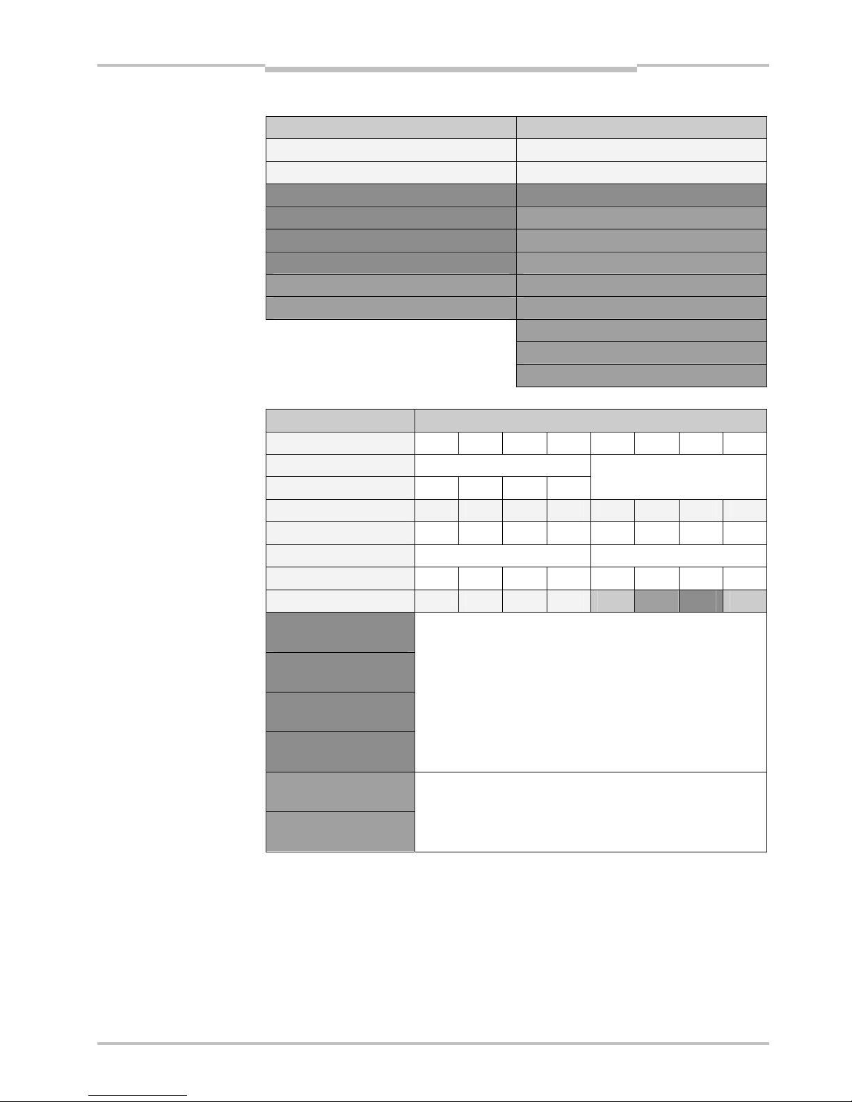
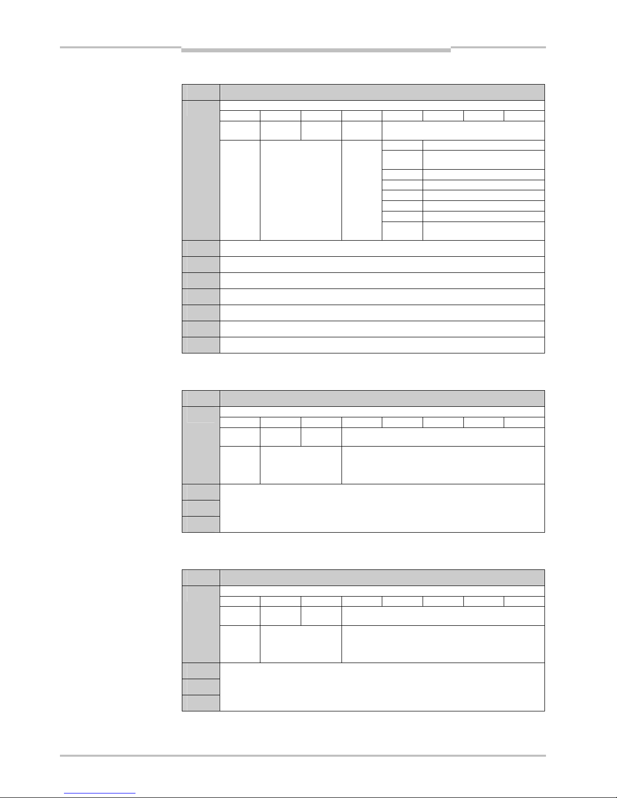
5.2.4 Beispielkonfiguration
Die farblichen Unterlegungen der einzelnen Prozessdaten-Bytes bis hin zu farblichen
Unterlegungen einzelner Bits sollen die Zusammenhänge der Prozessdaten zu den
einzelnen Modulen verdeutlichen.
PD-Breite (Byte) Slot Modul
IN OUT
Parameter Parameterwert
Betriebsart Port 1 SCAN-Mode
Betriebsart Port 2 Digital Input
Betriebsart Port 3 SCAN-Mode
Betriebsart Port 4 SIO Input mit
IO-Link-Zugriff
Diagnose
Kennungsbezogen
freigegeben
Diagnose
Modul-Status
freigegeben
Diagnose StatusMeldungen
freigegeben
Diagnose
Kanalgenau
freigegeben
Diagnose
IOL-Status
freigegeben
Diagnose Master freigegeben
Diagnose Port 1 freigegeben
Diagnose Port 2 freigegeben
Diagnose Port 3 freigegeben
Diagnose Port 4 freigegeben
Portfreigabe nach
Überlast
manuell freigeben
Failsafe-Code
Port 1
alle zurücksetzen
Failsafe-Code
Port 2
alle zurücksetzen
Failsafe-Code
Port 3
alle zurücksetzen
1 IO-Link Master
Status
2 2
Failsafe-Code
Port 4
alle zurücksetzen
Hinweis
Page 16

Kapitel 5 Betriebsanleitung
IOLSHPB-P3104R01
16 © SICK AG • Industrial Sensors • Deutschland • Irrtümer und Änderungen vorbehalten 2010-07-05
Inbetriebnahme und Betrieb
PD-Breite (Byte) Slot Modul
IN OUT
Parameter Parameterwert
Vendor_ID_1 0x00 (wird nicht
validiert)
Vendor_ID_2 0x00 (wird nicht
validiert)
Device_ID_1 0x00 (wird nicht
validiert)
Device_ID_2 0x00 (wird nicht
validiert)
2 IOL_I/O__4/_1
byte
4 1
Device_ID_3 0x00 (wird nicht
validiert)
3 digital Input 0 0
Vendor_ID_1 0x00 (wird validiert)
Vendor_ID_2 0x01 (wird validiert)
Device_ID_1 0x00
Device_ID_2 0x00
Device_ID_3 0x00
Deviceparameter 1 0xF1
Deviceparameter 2 0xF2
Deviceparameter 3 0xF3
Deviceparameter 4 0xF4
Deviceparameter 5 0xF5
Deviceparameter 6 0xF6
Deviceparameter 7 0xF7
Deviceparameter 8 0xF8
Deviceparameter 9 0xF9
Deviceparameter 10 0xFA
Deviceparameter 11 0xFB
4 IOL_I/O__2/_8
Byte + dev prm
2 8
Deviceparameter 12 0xFC
5 0 0 Vendor_ID_1 0xD0
Vendor_ID_2 0xD1
Device_ID_1 0xDA
Device_ID_2 0xDB
Device_ID_3 0xDC
6
Page 17
Betriebsanleitung Kapitel 5
IOLSHPB-P3104R01
2010-07-05 © SICK AG • Industrial Sensors • Deutschland • Irrtümer und Änderungen vorbehalten 17
Inbetriebnahme und Betrieb
Prozessdatenabbild der Beispielkonfiguration
Eingangs-Prozessdaten Ausgangs-Prozessdaten
„IOLM Status“ Byte 0 „IOLM Status“ Byte 0
„IOLM Status“ Byte 1 „IOLM Status“ Byte 1
„IOL_I/O__4/_1 byte Byte 0 „IOL_I/O__4/_1 byte Byte 0
„IOL_I/O__4/_1 byte Byte 1 „IOL_I/O__2/_8 Byte + dev prm“ Byte 0
„IOL_I/O__4/_1 byte Byte 2 „IOL_I/O__2/_8 Byte + dev prm“ Byte 1
„IOL_I/O__4/_1 byte Byte 2 „IOL_I/O__2/_8 Byte + dev prm“ Byte 2
„IOL_I/O__2/_8 Byte + dev prm“ Byte 0 „IOL_I/O__2/_8 Byte + dev prm“ Byte 3
„IOL_I/O__2/_8 Byte + dev prm“ Byte 1 „IOL_I/O__2/_8 Byte + dev prm“ Byte 4
„IOL_I/O__2/_8 Byte + dev prm“ Byte 5
„IOL_I/O__2/_8 Byte + dev prm“ Byte 6
„IOL_I/O__2/_8 Byte + dev prm“ Byte 7
Eingangs-Prozessdaten Belegung
„IOLM Status“ Byte 0 Bit 7 Bit 6 Bit 5 Bit 4 Bit 3 Bit 2 Bit 1 Bit 0
COM-States
Port4 Port3 Port2 Port1
reserviert
X X X X 0 0 0 0
„IOLM Status“ Byte 1 Bit 7 Bit 6 Bit 5 Bit 4 Bit 3 Bit 2 Bit 1 Bit 0
PD-Vaild States Digital Input States
Port4 Port3 Port2 Port1 Port4 Port3 Port2 Port1
X X X X X X X X
„IOL_I/O__4/_1 byte“
Byte 0
„IOL_I/O__4/_1 byte“
Byte 1
„IOL_I/O__4/_1 byte“
Byte 2
„IOL_I/O__4/_1 byte“
Byte 3
siehe IOLD-Herstellerbeschreibung
„IOL_I/O__2/_8 Byte +
dev prm“ Byte 0
„IOL_I/O__2/_8 Byte +
dev prm“ Byte 1
siehe IOLD-Herstellerbeschreibung
Wenn eine IOL-Kommunikation aktiv ist, bedeutet dies nicht automatisch, dass die
Prozessdaten des IOLD gültig sind. Dies kann verschiedene Gründe haben, z. B. war die
Validierung nicht erfolgreich oder das IOLD meldet von sich aus einen Fehlerzustand.
Hinweis
Page 18

Kapitel 5 Betriebsanleitung
IOLSHPB-P3104R01
18 © SICK AG • Industrial Sensors • Deutschland • Irrtümer und Änderungen vorbehalten 2010-07-05
Inbetriebnahme und Betrieb
Ausgangs-Prozessdaten Belegung
„IOLM Status“ Byte 0 Bit 7 Bit 6 Bit 5 Bit 4 Bit 3 Bit 2 Bit 1 Bit 0
reserviert
0 0 0 0 0 0 0 0
„IOLM Status“ Byte 1 Bit 7 Bit 6 Bit 5 Bit 4 Bit 3 Bit 2 Bit 1 Bit 0
digital Ouput States
reserviert
Port4 Port3 Port2 Port1
X X X X X X X X
„IOL_I/O__4/_1 byte“
Byte 0
siehe IOLD-Herstellerbeschreibung
„IOL_I/O__2/_8 Byte +
dev prm“ Byte 0
„IOL_I/O__2/_8 Byte +
dev prm“ Byte 1
„IOL_I/O__2/_8 Byte +
dev prm“ Byte 2
„IOL_I/O__2/_8 Byte +
dev prm“ Byte 3
„IOL_I/O__2/_8 Byte +
dev prm“ Byte 4
„IOL_I/O__2/_8 Byte +
dev prm“ Byte 5
„IOL_I/O__2/_8 Byte +
dev prm“ Byte 6
„IOL_I/O__2/_8 Byte +
dev prm“ Byte 7
siehe IOLD-Herstellerbeschreibung
Die farblichen Unterlegungen der einzelnen Prozessdaten-Bytes bis hin zu farblichen
Unterlegungen einzelner Bits sollen die Zusammenhänge der Prozessdaten zu den
einzelnen Modulen verdeutlichen.
Hinweis
Page 19

Betriebsanleitung Kapitel 5
IOLSHPB-P3104R01
2010-07-05 © SICK AG • Industrial Sensors • Deutschland • Irrtümer und Änderungen vorbehalten 19
Inbetriebnahme und Betrieb
5.3 Bedeutung der Prozessdaten des IO-Link Master Status
Eingangs-Prozessdaten
1 IO-Link-Kommunikation aktiv. Com States
(Port n)
0 IO-Link-Kommunikation nicht aktiv.
1 Eingangs-Prozessdaten des IOLD sind gültig. PD-Valid
States
(Port n)
0 Eingangs-Prozessdaten des IOLD sind nicht
gültig.
1 Digitaler Eingang ist gesetzt.
IO-Link Master
Status
SIO-IN /
digital Input
States
(Port n)
0 Digitaler Eingang ist nicht gesetzt.
Ausgangs-Prozessdaten
1 Digitaler Ausgang wird gesetzt, rücklesbar über
digital Input States.
IO-Link Master
Status
digitale
Outputs
(Port n)
0 Digitaler Ausgang wird nicht gesetzt, rücklesbar
über digital Input States.
5.4 Objekte des Masters
Slot Index-Nr. Inhalt/Funktion Zugriff
IOLM Control (1 Byte)
Mit diesem Objekt können Fehler- oder Diagnose-
zustände zurückgesetzt werden.
Durch ein eingesetztes Bit wird die entsprechende
Aktion ausgeführt.
Bit 1 (LSB) = reserviert
Bit 2 = Portfreigabe (Überlastete Ports
werden wieder freigegeben.)
Bit 3 = reserviert
Bit 4 = reserviert
Bit 5 = reserviert
Bit 6 = reserviert
Bit 7 = reserviert
0 4
Bit 8 (MSB) = reserviert
Write only
Status der IO-Link-Verbindungen, pro Port = 3 Byte
Byte 1 = Portnummer
Byte 2 = Status der Verbindung
00
hex
in DIO
01
hex
in Kommunikation
FF
hex
fehlerhafte Kommunikation
(kein IOL-Device)
0 5
Byte 3 = reserviert (00
hex
)
Read only
Page 20

Kapitel 5 Betriebsanleitung
IOLSHPB-P3104R01
20 © SICK AG • Industrial Sensors • Deutschland • Irrtümer und Änderungen vorbehalten 2010-07-05
Inbetriebnahme und Betrieb
Slot Index-Nr. Inhalt/Funktion Zugriff
Portkonfiguration, Parameter zur Konfiguration der
Betriebsart der Ports
Byte 1 Betriebsart
Port 1
Physik/Port
zyklus
1101
bin
XXXX
bin
Physik 2
(3-Leiter)/frei
other XXXX
bin
reserviert
Betriebs-
modus
XXXX
bin
0001
bin
digitaler Ein-
gang (SIOMode-DI)
XXXX
bin
0010
bin
digitaler Aus-
gang (SIOMode-DO)
XXXX
bin
0011
bin
SCAN-Mode
XXXX
bin
1001
bin
SIO-IN (mit
IO-LinkZugriff)
XXXX
bin
other reserviert
Byte 2 = reserviert
Byte 3 = Betriebsart Port 2
Byte 4 = reserviert
Byte 5 = Betriebsart Port 3
Byte 6 = reserviert
Byte 7 = Betriebsart Port 4
0 128
Byte 8 = reserviert
Read/Write
Page 21

Betriebsanleitung Kapitel 5
IOLSHPB-P3104R01
2010-07-05 © SICK AG • Industrial Sensors • Deutschland • Irrtümer und Änderungen vorbehalten 21
Inbetriebnahme und Betrieb
Slot Index-Nr. Inhalt/Funktion Zugriff
Status aller Ports
Byte 1 Betriebsart
Port 1
Physik/Port
zyklus
1101
bin
XXXX
bin
Physik 2 (3-
Leiter)/frei
Betriebs-
modus
XXXX
bin
0001
bin
digitaler Ein-
gang (SIOMode-DI)
XXXX
bin
0010
bin
digitaler Aus-
gang (SIOMode-DO)
XXXX
bin
0011
bin
SCAN-Mode
XXXX
bin
0100
bin
COM1-Mode
XXXX
bin
0101
bin
COM2-Mode
XXXX
bin
0110in COM3-Mode
XXXX
bin
1001
bin
SIO-IN (mit
IO-LinkAccess)
XXXX
bin
0101
bin
reserviert
Byte 2 = Zykluszeit Port 1
Byte 3 = Status Port 2
Byte 4 = Zykluszeit Port 2
Byte 5 = Status Port 3
Byte 6 = Zykluszeit Port 3
Byte 7 = Status Port 4
0 144
Byte 8 = Zykluszeit Port 4
Read only
Service Response Timeout-Wert der IO-Link-Ports. Zeit
(Wert x100) in ms, welche das IOLD hat, um eine
gültige Service Response auf ein Service Request zu
senden.
min: 10 (1,0 s Timeout)
max: 255 (25,5 s Timeout)
default: 100 (10, 0 s Timeout)
Byte 1 Wert x 100 ms = Port 1 Service Response
Timeout
Byte 2 Wert x 100 ms = Port 2 Service Response
Timeout
Byte 3 Wert x 100 ms = Port 3 Service Response
Timeout
0 145
Byte 4 Wert x 100 ms = Port 4 Service Response
Timeout
Read/Write
Page 22

Kapitel 5 Betriebsanleitung
IOLSHPB-P3104R01
22 © SICK AG • Industrial Sensors • Deutschland • Irrtümer und Änderungen vorbehalten 2010-07-05
Inbetriebnahme und Betrieb
Slot Index-Nr. Inhalt/Funktion Zugriff
Versorgungsspannungs-Zustände des Gerätes:
Bit 0: Überlast Device-Versorgung
Port 1
Bit 1: Überlast Device-Versorgung
Port 2
Bit 2: Überlast Device-Versorgung
Port 3
Bit 3: Überlast Device-Versorgung
Port 4
Bit 4: Zustand der 24-V-
Versorgungsspannung U
S
Bit 5 … Bit 7: 0
Überlast Device-Versorgung:
0: OK
1: Überlast
24-V-Versorgungsspannung:
0: OK
0 146
1: nicht ausreichend
Read only
0 161 IOLD_PD_Out_1 Ausgangsdaten des IO-Link-
Devices an Port 1 im COMMode.
Die zurückgegebene Datenlänge entspricht der Datenlänge des IO-Link-Devices an
Port 1 im COM-Mode.
Read only
0 162 IOLD_PD_Out_2 Ausgangsdaten des IO-Link-
Devices an Port 2 im COMMode.
Die zurückgegebene Datenlänge entspricht der Datenlänge des IO-Link-Devices an
Port 2 im COM-Mode.
Read only
0 163 IOLD_PD_Out_3 Ausgangsdaten des IO-Link-
Devices an Port 3 im COMMode.
Die zurückgegebene Datenlänge entspricht der Datenlänge des IO-Link-Devices an
Port 3 im COM-Mode.
Read only
Page 23

Betriebsanleitung Kapitel 5
IOLSHPB-P3104R01
2010-07-05 © SICK AG • Industrial Sensors • Deutschland • Irrtümer und Änderungen vorbehalten 23
Inbetriebnahme und Betrieb
Slot Index-Nr. Inhalt/Funktion Zugriff
0 164 IOLD_PD_Out_4 Ausgangsdaten des IO-Link-
Devices an Port 4 im COMMode.
Die zurückgegebene Datenlänge entspricht der Datenlänge des IO-Link-Devices an
Port 4 im COM-Mode.
Read only
0 177 IOLD_PD_In_1 Eingangsdaten des IO-Link-
Devices an Port 1 im COMMode
Die zurückgegebene Datenlänge entspricht der Datenlänge des IO-Link-Devices an
Port 1 im COM-Mode.
Read only
0 178 IOLD_PD_In_2 Eingangsdaten des IO-Link-
Devices an Port 2 im COMMode.
Die zurückgegebene Datenlänge entspricht der Datenlänge des IO-Link-Devices an
Port 2 im COM-Mode.
Read only
0 179 IOLD_PD_In_3 Eingangsdaten des IO-Link-
Devices an Port 3 im COMMode.
Die zurückgegebene Datenlänge entspricht der Datenlänge des IO-Link-Devices an
Port 3 im COM-Mode.
Read only
0 180 IOLD_PD_In_4 Eingangsdaten des IO-Link-
Devices an Port 4 im COMMode.
Die zurückgegebene Datenlänge entspricht der Datenlänge des IO-Link-Devices an
Port 4 im COM-Mode.
Read only
1 0-254 Für den Device an Port 1 wird automatisch ein Read-/
Write-Request auf entsprechendem Index erzeugt.
(SubIndex = 0 )
Read/Write
2 0-254 Für den Device an Port 2 wird automatisch ein Read-/
Write-Request auf entsprechendem Index erzeugt.
(SubIndex = 0 )
Read/Write
3 0-254 Für den Device an Port 3 wird automatisch ein Read-/
Write-Request auf entsprechendem Index erzeugt.
(SubIndex = 0 )
Read/Write
4 0-254 Für den Device an Port 4 wird automatisch ein Read-/
Write-Request auf entsprechendem Index erzeugt.
(SubIndex = 0 )
Read/Write
Page 24

Kapitel 5 Betriebsanleitung
IOLSHPB-P3104R01
24 © SICK AG • Industrial Sensors • Deutschland • Irrtümer und Änderungen vorbehalten 2010-07-05
Inbetriebnahme und Betrieb
5.5 IO-Link CALL
Der IO-Link CALL ist ein standardisierter Lese- und Schreibzugriff auf die IOLD-Objekte.
Dieser nutzt die Mechanismen der PROFIBUS-I&M Funktionen (über DP/V1).
Den Funktionsbaustein finden Sie auf der Homepage der jeweiligen Systemhersteller.
Eine Kommunikation mit einem angeschlossenen Sensor über IO-Link ist nur dann
möglich, wenn:
der Port im IO-Link-Modus ist,
das entsprechende Statusbit in den Eingangs-Prozessdaten gesetzt ist und wenn der
Status der Verbindung „in Kommunikation“ ist, siehe Kapitel 5.4 „Objekte des Masters“
auf Seite 19 (Slot 0, Index 5, Byte 2).
5.6 IO-Link-Kommunikation direkt über DP/V1
(mit Slot und Index)
Über einen DP/V1-Schreib-Dienst oder DP/V1-Lese-Dienst kann direkt auf IOLD-Objekte
zugegriffen werden.
Die Slotnummer des Dienstes muss hierbei der Portnummer des gewünschten IOLD
entsprechen. Der V1-Index muss dem IO-Link-Device-Objekt-Index entsprechen.
Den Funktionsbaustein finden Sie auf der Homepage der jeweiligen Systemhersteller.
Die Ähnlichkeit von Struktur und Funktion des IO-Link-Service-Kanals und DP/V1-Kanals
ermöglicht einen effektiven Zugriff auf IO-Link-Device-Datenobjekte. Die „normalen“ Leseund Schreibdienste, die der Kanal zu Verfügung stellt, werden auf den IO-Link-ServiceKanal abgebildet. Ausnahmen sind Index 0 und 1. Auf diese werden die direkten
Parameter abgebildet. Ein Datenaustausch ist nur möglich, wenn die IO-LinkKommunikation mit dem IO-Link-Device aktiv ist, d. h. wenn der entsprechende Status
COMx gesetzt ist, siehe Kapitel 5.4 „Objekte des Masters“ auf Seite 19, „Port Status“
(Slot-Nr. 0).
Dabei entsprechen:
Slot-Nr. = Portnummer des IO-Link-Devices, Slot-Nr. 1 ... 4
DP/V1-Index 0 = Direkte Parameter 0 ... 15
DP/V1-Index 1 = Direkte Parameter 16 ... 31
DP/V1-Index 0 ... 254 = IO-Link-Service-PDU-Index
(ohne Subindex, dieser wird immer „0“ gesetzt)
Beispiel
Der „Vendor Name“ eines IOLD hat nach IO-Link Communication Specification den fest
definierten IOL-Index 16 (0x10). Der Datentyp ist ein Visible-String von maximal 64 Byte
Länge. Der „Vendor Name“ des IOLD an Port 3 soll gelesen werden.
Dafür ist ein DP/V1-Lese-Dienst mit Slot 3 Index 16 auszuführen.
Wenn die IO-Link-Kommunikation an diesem Port aktiv ist, wird vom IOLM ein IO-Link Read
Service Request auf den an Port 3 angeschlossenen IOLD durchgeführt.
Die IO-Link-Read-Service-Response-Daten des IOLD werden vom IOLM transparent auf den
Responsedaten des DP/V1-Lese-Dienstes abgebildet.
Bei einer negativen IO-Link Read Service Response wird eine entsprechende negative
DP/V1-Lese-Dienst-Response zurückgegeben.
Hinweis
Page 25

Betriebsanleitung Kapitel 5
IOLSHPB-P3104R01
2010-07-05 © SICK AG • Industrial Sensors • Deutschland • Irrtümer und Änderungen vorbehalten 25
Inbetriebnahme und Betrieb
5.7 IO-Link-Kommunikation indirekt über DP/V0
5.7.1 Die azyklische Kommunkation über Prozessdaten (DP/V0)
Die DP/V1-Kommunikation ist im Vergleich zur zyklischen DP/V0-Kommunikation relativ
neu. Die Lebensdauer von Steuerungen und Anlagen ist dagegen jedoch so groß, dass
Erweiterungen und Umrüstungen stattfinden. Die Steuerung ist oft noch nicht DP/V1-fähig,
soll aber dennoch komplexe Teilnehmer bedienen können.
Zu diesem Zweck ist die Bedienung azyklischer Dienste auch innerhalb der Prozessdaten
möglich. D. h. auch eine Steuerung, die kein DP/V1 beherrscht, kann ohne weiteres komplexe Geräte, z. B. einen IO-Link-Master, bedienen.
Informationen zur IO-Link-Kommunikation und zur Service-PDU finden Sie in der IO-LinkSpezifikation, Version 1.0.
5.7.2 Mechanismus der Übertragung in den Prozessdaten
Das VC1-Gerät ist ein „fest installiertes“ virtuelles Gerät des IO-Link-Masters, weil die
Prozessdaten zur Übertragung von Kommunikationsdaten (Service-PDU) genutzt werden
können. Während des aktiven Prozessdatenaustausches ist es möglich, das VC1-Gerät
den einzelnen Ports des Masters und deren Kommunikationsobjekten sequentiell zuzuordnen und parallel zu den Prozessdaten auch Service-PDU-Daten auszutauschen.
Die Prozessdatenbreite, die das VC1-Gerät dabei im Prozessdatenkanal belegt, hat eine
parametrierbare Länge von 4 bis 16 Worten, siehe Tabelle in Abschnitt 5.2.1.
Da die Datenbreite des VC1-Gerätes 4 Worte beträgt, der Nutzdatenumfang jedoch bis zu
240 Byte je Kommunikation umfassen darf, kann es nötig sein, Daten in mehreren
Schritten fragmentiert zu übertragen.
Daher gibt es ein:
Startfragment,
Fortsetzungsfragment,
Abschlussfragment,
Fehler- oder Abbruchfragment.
In jedem Fragment gibt es ein Dienst-Byte, das jeweils eine genaue Zuordnung des
Fragmentes erlaubt. Im Folgenden sind die einzelnen Fragmente und das Dienst-Byte
detailliert erläutert.
Page 26
Kapitel 5 Betriebsanleitung
IOLSHPB-P3104R01
26 © SICK AG • Industrial Sensors • Deutschland • Irrtümer und Änderungen vorbehalten 2010-07-05
Inbetriebnahme und Betrieb
Startfragment (8 Byte)
Byte Beschreibung
Dienst im Startfragment
Bit 7 Bit 6 Bit 5 Bit 4 Bit 3 Bit 2 Bit 1 Bit 0
Request/
Response
0 0 Fragmen-
tierung
Aktion
00
hex
Keine Aktion (clear/reset)
01
hex
bis 02
hex
Reserviert
03
hex
Read-Dienst
04
hex
Write-Dienst
05
hex
Reserviert
06
hex
Read-Dienst
07
hex
Write-Dienst
1
„0“ =
Request
„1“ =
Response
Fragmenttyp:
„00“ = Startfragment
„1“ = fragmentiert
„0“ = nicht
fragmentiert
08
hex
bis 0F
hex
Reserviert
2
Gerätenummer
3
Invoke-ID (Kanal/Slot)
4
Index High
5
Index Low
6
Subindex
7
Länge, falls erforderlich
8
Datenblock, falls erforderlich
Fortsetzungsfragment (8 Byte)
Byte Beschreibung
Dienst im Fortsetzungsfragment
Bit 7 Bit 6 Bit 5 Bit 4 Bit 3 Bit 2 Bit 1 Bit 0
Request/
Response
0 1 Fragmentnummer (01
hex
bis 1F
hex
)
1
„0“ =
Request
„1“ =
Response
Fragmenttyp:
„01“ = Fortsetzungs-
fragment
Zähler:
Fragmentnummer (01
hex
bis 1F
hex
)
2
…
8
Datenblock, falls erforderlich
Abschlussfragment (8 Byte)
Byte Beschreibung
Dienst im Abschlussfragment
Bit 7 Bit 6 Bit 5 Bit 4 Bit 3 Bit 2 Bit 1 Bit 0
Request/
Response
1 0
Reserviert
1
„0“ =
Request
„1“ =
Response
Fragmenttyp:
„10“ = Endfragment
(Abschlussfragment)
Reserviert
2
…
8
Datenblock, falls erforderlich
Page 27

Betriebsanleitung Kapitel 5
IOLSHPB-P3104R01
2010-07-05 © SICK AG • Industrial Sensors • Deutschland • Irrtümer und Änderungen vorbehalten 27
Inbetriebnahme und Betrieb
Abbruchfragment
Byte Beschreibung
Dienst im Abschlussfragment
Bit 7 Bit 6 Bit 5 Bit 4 Bit 3 Bit 2 Bit 1 Bit 0
Request/
Response
1 1 Reserviert
1
„0“ =
Request
„1“ =
Response
Fragmenttyp
„11“ = Abbruch-/Fehler-
fragment
Reserviert
2
…
8
Error-Code, falls erforderlich
5.7.3 Vorgehensweise bei der Übertragung
Nach jedem Request wird ein Response gesendet. Dieses Response zeigt jeweils an, dass
der Request empfangen wurde und welcher Status derzeit vorliegt:
Byte Beschreibung
1 Dienst (gespiegelter Request mit gesetztem Response-Bit)
2 Status, falls erforderlich
3 Länge nur beim ersten Read-Response
4
…
n
Datenblock, falls erforderlich
Der Status wird bei Abschluss der lokalen Service-PDU-Übertragung sowie im Fehlerfall
angezeigt. Der Datenblock kann im Fehlerfall Details liefern. Von einem Fehler muss
ausgegangen werden, wenn das Status-Byte einen Wert ungleich 00
hex
annimmt.
00
hex
kein Fehler
44
hex
Fehler bei der Kommunikation
Weitere Fehler (noch nicht festgelegt)
Page 28

Kapitel 5 Betriebsanleitung
IOLSHPB-P3104R01
28 © SICK AG • Industrial Sensors • Deutschland • Irrtümer und Änderungen vorbehalten 2010-07-05
Inbetriebnahme und Betrieb
5.8 Die Parameter bei VC1 haben folgende Bedeutung:
5.8.1 Allgemein
Gerätenummer
Ein „Stand alone“-IO-Link-Master hat die Gerätenummer 0.
Invoke-ID (Kanal/Slot)
Die Invoke-ID hat eine Länge von einem Byte und wird nur bei einigen Geräten verwendet.
Bei einem IO-Link-Master bezeichnet die Invoke-ID dessen Ports.
0 = bezeichnet den IO-Link-Master selber
1 = den Device an Port 1
n = den Device an Port n
Index High und Index Low
Hiermit wird der Objekt-Index des angesprochenen Objektes in zwei Byte angegeben.
Das gilt auch für Objekte auf dem IO-Link-Master.
Subindex
Der Subindex erlaubt bei einem IO-Link-Objekt die Auswahl eines bestimmten Elementes
aus einem Array oder einem Record. Bei Zugriffen auf einen IO-Link-Device ist folglich der
Subindex immer anzugeben.
Subindex 0 = alle Elemente des Objektes
Subindex 1 = erstes Element des Objektes
Subindex n = n-tes Element des Objektes
Länge
Dieser Wert gibt an, wieviel Byte Objektdaten (Objektinhalte) anschließend folgen. Es kann
sich je nach angesprochenem Slot (Invoke-ID) um Objektdaten des IO-Link-Masters oder
um Objektdaten eines angeschlossenen IO-Link-Devices handeln.
Datenblock
Dies sind ausschließlich die Inhalte eines Objektes. Die Länge und der Umfang der Objektdaten werden bereits zuvor durch den Parameter Länge beschrieben. Zur Verdeutlichung
sollen im Folgenden Beispiele von Diensten dargestellt werden.
Page 29

Betriebsanleitung Kapitel 5
IOLSHPB-P3104R01
2010-07-05 © SICK AG • Industrial Sensors • Deutschland • Irrtümer und Änderungen vorbehalten 29
Inbetriebnahme und Betrieb
5.8.2 Beispiel 1
Lesen des Gerätetyps des Devices an Port 3 (hier „WL12GLAS“ auf Index 1702dec,
SubIndex 2dec):
Read-Request (Master -> Device)
PD-Daten des Tunnels (4 Worte VC1) hex Struktur der Daten
03 / 00 / 03 / 06 A6 / 02 / 00 00 Read-Request IO-Link-Master/Geräte-
nummer/Port/Index High Index
Low/Subindex/2 Byte ungenutzt
Read-Response (Device -> Master)
PD-Daten des Tunnels (4 Worte VC1) hex Struktur der Daten
93 / 00 / 08 / 57 42 31 32 47 Read-Response/Status/Länge/5 Byte
Objektdaten
Read-Request (Master -> Device)
PD-Daten des Tunnels (4 Worte VC1) hex Struktur der Daten
93 / xx xx xx xx xx xx xx Quittierung Startfragment/7 Byte
ungenutzt
Read-Response (Device -> Master)
PD-Daten des Tunnels (4 Worte VC1) hex Struktur der Daten
C0 / 4C 41 53 / 00 00 00 00 Abschlussfragment/3 Byte Objektdaten/
4 Byte ungenutzt
In der Read-Response erhält man, wie erwartet, die oben beschriebenen 8 Byte des
Objektes von Index 1702, SubIndex 2 des angeschlossenen Sensors. Die ersten 5 ByteObjektdaten werden im Startfragment übertragen, die fehlenden 3 Byte folgen im zweiten
und bereits letzten Fragment. Das Statusbyte zeigt an, dass die Kommunikation fehlerfrei
war.
Page 30

Kapitel 5 Betriebsanleitung
IOLSHPB-P3104R01
30 © SICK AG • Industrial Sensors • Deutschland • Irrtümer und Änderungen vorbehalten 2010-07-05
Inbetriebnahme und Betrieb
5.8.3 Beispiel 2
Schreiben eines Strings (Länge 10 Byte) auf den Device an Port 4 (hier „Alles i.O.“ auf
Index 67dec, SubIndex 3dec):
Write-Request (Master -> Device)
PD-Daten des Tunnels (4 Worte VC1) hex Struktur der Daten
14 / 00 / 04 / 00 43 / 03 / 41 6C Write-Request IO-Link-Master/Gerätenum-
mer/Port/Index High Index Low/Subindex/
2 Byte Objektdaten
Write-Response (Device -> Master)
PD-Daten des Tunnels (4 Worte VC1) hex Struktur der Daten
14 / xx xx xx xx xx xx xx Response/7 Byte ungenutzt
Write-Request (Master -> Device)
PD-Daten des Tunnels (4 Worte VC1) hex Struktur der Daten
21 / 6C 6C 73 20 69 2E 4F 1. Fortsetzungsfragment/7 Byte
Objektdaten
Write-Response (Device -> Master)
PD-Daten des Tunnels (4 Worte VC1) hex Struktur der Daten
21 / xx xx xx xx xx xx xx Response/7 Byte ungenutzt
Write-Request (Master -> Device)
PD-Daten des Tunnels (4 Worte VC1) hex Struktur der Daten
40 / 2E / xx xx xx xx xx xx Abschlussfragment/1 Byte Objektdaten/
6 Byte ungenutzt
Write-Response (Device -> Master)
PD-Daten des Tunnels (4 Worte VC1) hex Struktur der Daten
84 / 00 / xx xx xx xx xx xx Response/Status/6 Byte ungenutzt
Clear-Request (Master -> Device)
PD-Daten des Tunnels (4 Worte VC1) hex Struktur der Daten
00 / 00 00 00 00 00 00 00 Response/Status/6 Byte ungenutzt
Clear-Response (Device -> Master)
PD-Daten des Tunnels (4 Worte VC1) hex Struktur der Daten
00 / 00 00 00 00 00 00 00 Clear-Response
Hier wird die Write-Vorgabe in drei Fragmenten gemacht. Erst nach dem Empfang des
letzten Fragments übernimmt der IO-Link-Master die Anforderung. Die Response „84“
zeigt, dass das Kommando „04“ ausgeführt wurde. Mit dem Status „0“ wird gezeigt, dass
die Übertragung erfolgreich war.
Mit einem „Clear“ können die Kommunikationsdaten wieder in ihren Ausgangszustand
gesetzt werden.
Page 31

Betriebsanleitung Kapitel 6
IOLSHPB-P3104R01
2010-07-05 © SICK AG • Industrial Sensors • Deutschland • Irrtümer und Änderungen vorbehalten 31
Diagnose
6 Diagnose
6.1 Lokale Diagnose und Statusanzeigen
49,3
31
7040
871
861
0
2
6
4
8
9
x1
0
2
6
4
8
10
12x10
OUT
U
LS
BUS
IN
IN
U
LS
OUT
UL
US
BF
I1 X1
I2 X2
I3 X3
I4 X4
1
2
ß
5
6
9
3
4
87
Bezeichnung Farbe Bedeutung
LED grün Logikversorgung
Grün ein: Logikversorgung ist ausreichend
UL
Grün aus: Logikversorgung ist nicht ausreichend
LED rot Buskommunikation
Rot ein: – Slaveadresse ungültig
(außerhalb des Wertebereichs von 1 bis 126)
– PROFIBUS-DP nicht angeschlossen
– Master nicht aktiv
– Fehlerhafte Einstellung
(Masterprojektierung, Stationsadresse)
– Synchronisierung oder Parametrierung läuft,
Timeout ist abgelaufen
BF
Rot aus: – Gerät wird vom Master angesprochen und befindet sich
im Zustand „Zyklischer Prozessdatenaustausch“.
– Fehlende Geräteversorgung
A
bb. 2: Diagnose- und Statusanzeigen des Feldmoduls
IOLSHPB-P3104R01
1 Bus INs
2 Bus OUT
3 Versorgungsspannung IN
4 LED US
5 Port 1 … 4
6 Versorgungsspannung OUT
7 LED BF
8 LED UL
9 X1/X10
ß LED Port 1 … 4
Page 32

Kapitel 6 Betriebsanleitung
IOLSHPB-P3104R01
32 © SICK AG • Industrial Sensors • Deutschland • Irrtümer und Änderungen vorbehalten 2010-07-05
Diagnose
Bezeichnung Farbe Bedeutung
LED
grün/gelb/rot
Status der IO-Link-Ports
Grün ein: IO-Link-Kommunikation aktiv
Gelb ein: Im DIO-Modus ist der digitale Ein-oder Ausgang gesetzt.
Rot ein: – Im IO-Link-Modus:
IO-Link-Kommunikationsfehler
– Im DIO-Modus:
Überlast der L+/ L- Leitung
Port X1 bis
Port X4
LED aus: Im DIO-Modus ist der digitale Ein-oder Ausgang nicht
gesetzt.
LED
grün/rot
Spannungsversorgung für Port X1 bis Port X4
Grün ein: Spannungsversorgung ist ausreichend
Rot ein: Spannungsversorgung ist nicht ausreichend oder Überlast
US
LED aus: Spannungsversorgung ist nicht vorhanden
6.2 Diagnosedaten über den PROFIBUS
Das Diagnosekonzept des IOLM besteht aus zwei Komponenten. Zum einen werden die
Diagnosedaten über den PROFIBUS dem Steuerungssystem in Form von Diagnosebytes
zur Verfügung gestellt. Zum anderen ist es die Vor-Ort-Diagnose, die durch bestimmte
Farb-Codes der LEDs auf dem IOLM die Fehlerart anzeigt.
Die PROFIBUS-Diagnose besteht aus fünf Blöcken:
1. PROFIBUS-Standard-Diagnose
2. Kennungsbezogene Diagnose
3. Port-Status
4. Kanalgenaue Diagnose
(auf PROFIBUS gemappte IO-Link-Events und IOLM-Diagnose)
5. Revision
6. IOL-Status-Meldungen
Byte Bit 7 Bit 6 Bit 5 Bit 4 Bit 3 Bit 2 Bit 1 Bit 0 Bedeutung
Block 1: PROFIBUS-Standard-Diagnose
1 X X X X X X X X Stationsstatus 1
2 X X X X X X X X Stationsstatus 2
3 X X X X X X X X Stationsstatus 3
4 X X X X X X X X PROFIBUS-Master-Adresse
5 0 0 0 0 1 0 1 0 Herstellerkennung High-Byte
(0A
hex
)
6 1 0 0 0 1 1 0 0 Herstellerkennung High-Byte
(8C
hex
)
Page 33

Betriebsanleitung Kapitel 6
IOLSHPB-P3104R01
2010-07-05 © SICK AG • Industrial Sensors • Deutschland • Irrtümer und Änderungen vorbehalten 33
Diagnose
Byte Bit 7 Bit 6 Bit 5 Bit 4 Bit 3 Bit 2 Bit 1 Bit 0 Bedeutung
Block 2: Kennungsbezogene Diagnose
7 0 1 L = Länge des Blocks Kennungsbezogene
Diagnose (Header)
8 0 0 0 0 P4 P3 P2 P1 Port 1 bis 4
Block 3: Port Status
8 0 0 L = Länge des Blocks Status (Header)
9 1 0 0 0 0 0 1 0 Status-Typ = Port Status
10 0 0 0 0 0 0 0 0 Slot (= 0 = allgemeiner
Status des IOLM)
11 0 0 0 0 0 0 SP Specifier
12 ST P 4 ST P 3 ST P 2 ST P 1 Status Port 1 bis 4
Block 4: Kanalgenaue Diagnose
(13) 1 0 Portnummer Kanalbezogene Diagnose
(Header) Portnummer (0 =
IOLM, 1-4 = IOLD Port)
(14) IO 0 0 0 0 0 0 0 IO = IN / OUT und IO-Link
(15) CT ET Kanal- und
Fehlertyp Portnummer
Es kann keine oder bis zu 10 kanalgenaue Diagnosen im Diagnose-Telegramm
enthalten sein. Liegt keine kanalgenaue Diagnose vor, ist dieser Teil des
Diagnose-Telegramms nicht vorhanden.
Wenn vorhanden, ergibt sich die Länge des Blocks der kanalgenauen Diagnose
zu: yx3 Byte, mit y = Anzahl der kanalgenauen Diagnosen.
Für die Berechnungen der Bytenummern bei vorhandener kanalgenauer Diagnose
ergeben sich folgende Formeln:
…
Byte-Nr. für kanalbezogene Diagnose Header (n)
Byte-Nr. für IN/OUT und IO-Link Portnummer (n)
Byte-Nr. für Kanal-/Fehlertyp und Port.-Nr. (n)
= 12 + (nx3)-2
= 12 + (nx3)-1
= 12 + (nx3)-0
Block 5: Revisionsdiagnose
1 1 X X X X X X Revision (Start mit C1) k
k = 13 + (nx3) ((nx3) = Länge der kanalgenauen Diagnose (Byte))
Block 6: IO-Link spezifische Diagnose
k+1 0 0 Länge des Blocks
(Header + m IO-Link-Status)
Device-spezifische Diagnose
(IO-Link-Diagnose)
k+2 1 0 0 0 0 0 0 1 Statusmodell:
Status Message
k+3 0 0 0 0 0 0 0 0 Slot-Nr. (immer 0)
k+4 0 0 0 0 0 0 0 0 Status Spezifizierung
(keine Spezifizierung)
k+5 0 0 0 0 0 0 0 1 Status Daten-Beschreibung
(IOL-StatusDataDescription)
k+6 X X X X X X X X EventCode High-Byte
k+7 X X X X X X X X EventCode Low-Byte
Page 34

Kapitel 6 Betriebsanleitung
IOLSHPB-P3104R01
34 © SICK AG • Industrial Sensors • Deutschland • Irrtümer und Änderungen vorbehalten 2010-07-05
Diagnose
Byte Bit 7 Bit 6 Bit 5 Bit 4 Bit 3 Bit 2 Bit 1 Bit 0 Bedeutung
k+8 X X X X X X X X Portnummer
k+9 X X X X X X X X Event-Klassifizierung nach
IO-Link-Spezifikation
Es kann keine oder bis zu 10 kanalgenaue Diagnosen im Diagnose-Telegramm
enthalten sein. Liegt keine kanalgenaue Diagnose vor, ist dieser Teil des
Diagnose-Telegramms nicht vorhanden.
Wenn vorhanden, ergibt sich die Länge des Blocks bei IO-Link-Status-Meldungen
wie folgt: 5 + (zx4) Byte mit z = Anzahl der IO-Link-Status-Meldungen
Für die Berechnungen der Bytenummern bei vorhandener kanalgenauer Diagnose
ergeben sich folgende Formeln:
…
Byte-Nr. für EventCode High-Byte (i)
Byte-Nr. für EventCode Low-Byte (i)
Byte-Nr. für Portnummer (i)
Byte-Nr. für Event-Klassifizierung (i)
= k + 5 + (ix4)-3
= k + 5 + (ix4)-2
= k + 5 + (ix4)-1
= k + 5 + (ix4)-0
6.2.1 Block 1: PROFIBUS-Standard-Diagnose
X: Wert 1 ist aktiviert. Wert 0 ist deaktiviert.
M: Slave sendet 0, Master ergänzt falls nötig.
Byte Beschreibung
Stationsstatus 1
Bit 7 Bit 6 Bit 5 Bit 4 Bit 3 Bit 2 Bit 1 Bit 0
M Station existiert nicht.
X Slave ist nicht bereit für
den Datenaustausch.
X Fehler im Konfigurations-
telegramm
X Im Telegramm folgt eine
erweiterte Diagnose.
X Angeforderte Funktion wird
vom Slave nicht unterstützt.
M Ungültige Antwort vom Slave
X Fehler im Parameter-
telegramm
1
M Slave ist von einem
anderem Master belegt.
Page 35

Betriebsanleitung Kapitel 6
IOLSHPB-P3104R01
2010-07-05 © SICK AG • Industrial Sensors • Deutschland • Irrtümer und Änderungen vorbehalten 35
Diagnose
Byte Beschreibung
Stationstatus 2
Bit 7 Bit 6 Bit 5 Bit 4 Bit 3 Bit 2 Bit 1 Bit 0
X Slave muss neu
parametriert werden.
X Statische Diagnose
1 Fest auf 1 für DP-Betrieb
X Watchdog ist aktiviert.
X Freeze-Kommando erhalten.
X Sync-Kommando erhalten.
0 Reserviert
2
M Slave ist deaktiviert.
Stationsstatus 3
Bit 7 Bit 6 Bit 5 Bit 4 Bit 3 Bit 2 Bit 1 Bit 0
0 0 0 0 0 0 0 Reserviert
3
X Slave hat mehr Diagnose-
informationen, als im Telegramm dargestellt werden.
PROFIBUS-Master-Adresse
Bit 7 Bit 6 Bit 5 Bit 4 Bit 3 Bit 2 Bit 1 Bit 0
4
0-125 (0x00-0x7E) Adresse des Masters
nach Parametrierung,
Default ist 255 (0xFF)
Ident Number
Bit 7 Bit 6 Bit 5 Bit 4 Bit 3 Bit 2 Bit 1 Bit 0
0-225 (0x00-0xFF) Ident Number High Byte
5
und
6
0-225 (0x00-0xFF) Ident Number Low Byte
6.2.2 Block 2: Kennungsbezogene Diagnose
In Abschnitt 6.2 werden die fehlerhaften Ports angezeigt.
Für jeden fehlerhaften Port wird eine „1“ eingetragen.
Im ersten Byte des Blocks wird in Bit 0 bis 5 die Länge L des gesamten kennungsbezogenen Diagnose-Blocks einschließlich Header angegeben.
Die Länge dieses Blocks ist 2 Byte.
6.2.3 Block 3: Status-PDU (Port-Status)
Für jeden Port gibt es 2 Bits, um den Zustand zu codieren:
ST Pn x: 00 = Daten des Ports sind gültig.
ST Pn x: 01 = Daten des Ports sind aufgrund eines Fehlers des IOLD ungültig.
ST Pn x: 10 = Daten des Ports sind ungültig, da ein falsches IOLD gesteckt ist.
ST Pn x: 11 = Daten des Ports sind ungültig, weil die IO-Link-Kommunikation
nicht aktiv ist (kein oder defektes IOLD).
Page 36

Kapitel 6 Betriebsanleitung
IOLSHPB-P3104R01
36 © SICK AG • Industrial Sensors • Deutschland • Irrtümer und Änderungen vorbehalten 2010-07-05
Diagnose
Der Specifier (SP) ist gleich 1, wenn ein fehlerhafter Zustand eintritt. Der Specifier ist
gleich 2, wenn der Port aus einem fehlerhaften in den fehlerfreien Zustand wechselt.
Bei 0 hat sich der Zustand nicht geändert.
SP: 0 = Keine Bewertung
SP: 1 = Fehler tritt auf (Anzahl > 0)
SP: 2 = Fehler verschwindet (Anzahl = 0)
SP: 3 = Reserviert
Im ersten Byte des Blocks wird in Bit 0 bis 5 die Länge L des gesamten Status-PDU-Blocks
einschließlich Header angegeben. Die Länge dieses Blocks ist 5.
6.2.4 Block 4: Kanalbezogene Diagnose
Bis zu zehn Fehler werden hier angezeigt. Pro Fehler gibt es 3 Byte, dieser Block kann
insgesamt maximal 30 Byte groß werden. Jeder Fehler ist in sich abgeschlossen zu
betrachten. Die Voraussetzung für die Anzeige der Fehler ist, dass das IOLD die IO-Link
Diagnose unterstützt und die kanalgenaue Diagnose des Gerätes aktiviert ist.
IO: 00
bin
= Reserviert
IO: 01
bin
= Input
IO: 10
bin
= Output
IO: 11
bin
= IO-Link
Channel: Portnummer des betroffenen Gerätekanals,
0 = IOLM
1 ... 4 = IOLM
CT: 000
bin
= Reserviert
ET:0 = Reserviert
ET: 1 = Kurzschluss
ET: 2 = Unterspannung
ET: 3 = Überspannung
ET: 4 = Überlast
ET: 5 = Übertemperatur
ET: 6 = Leitungsbruch
ET: 7 = Oberer Grenzwert überschritten
ET: 8 = Unterer Grenzwert überschritten
ET: 9 = Allgemeiner Fehler
6.2.5 Block 5: Revisionsdiagnose
Zeigt die Revision der Firmware an, z. B. 0xC3 = Revision 3.
Page 37

Betriebsanleitung Kapitel 6
IOLSHPB-P3104R01
2010-07-05 © SICK AG • Industrial Sensors • Deutschland • Irrtümer und Änderungen vorbehalten 37
Diagnose
6.2.6 Block 6: IO-Link-spezifische Diagnose
Statusmodell
Die Datenstruktur in der nachfolgenden Tabelle zeigt die Parametrierung des DiagnoseStatusmodells für PROFIBUS-DP. Die Status- und iPar-Meldung benutzen dasselbe Modell.
Sie unterscheiden sich im Status-Typ (1: Status-Meldung, 7: iPar-Meldung) und in den
Statusdaten:
1 = Status-Meldung
(Statusdaten enthalten die IOL_StatusDataDescription (IO-Link Event)
7 = iPar-Meldung
(Statusdaten enthalten die Daten der iPar Notification)
Struktur der Statusmeldungen
Oktett Bit 7 Bit 6 Bit 5 Bit 4 Bit 3 Bit 2 Bit 1 Bit 0
Header n
0 0 Länge des Blocks
Status-Typ
1 Status-Typ 1
Status-Typ:
(0): reserviert (8-29): reserviert
(1): Status Message (30): PrmCmdAck
(2): Modul_Status (31): Red_Stat
(3): DxB_Link_Status (32-125): herstellerspezifisch
(4-6): reserviert (126): PA-Profil
n+1
Statusm
odell
(7): iPar Notification (127) reserviert
Slotnummer n+2
Slotnummer
Status Spezifizierung
reserviert (voreingestellt „0“) X X
Status-Spezifikationen:
(0): keine weitere Differenzierung
(1): Status gekommen
(2): Status gegangen
n+3
(3): reserviert
Status Daten Beschreibung
0 0 0 0 0 0 0 0
n+4
(Status_Type =1) IOL_Status Meldung
(Status_Type =7) iPar Notification
Page 38

Kapitel 6 Betriebsanleitung
IOLSHPB-P3104R01
38 © SICK AG • Industrial Sensors • Deutschland • Irrtümer und Änderungen vorbehalten 2010-07-05
Diagnose
IOL_Status-Meldungen
Ein IOL_Status Meldungsblock beschreibt ein IO-Link-Ereignis und seine Attribute
eindeutig:
EventCode
Portnummer
Event-Klassifizierung
IOL_Status-Meldungen Größe Codierung Beschreibung
EventCode 2 Oktetts (0 … 65535) Der IO-Link EventCode ent-
spricht der IO-Link-Spezifikation [8].
(0): IOL-M Portnummer 1 Oktett
(1 … 63):
Portnummer (IOL-D)
Kanal-/Port-Selektor
Event-Klassifizierung 1 Oktett siehe nachfolgende
Tabelle
Die Event-Klassifizierung
entspricht der IO-Link-Spezifikation [8].
Nachfolgend wird die Bit-Struktur der Event-Klassifizierung definiert:
Bit Beschreibung
Event-Klassifizierung: Instanz 0 … 2
Die Bits 0 bis 2 bilden einen Vorgang ab, der durch ein Ereignis (Event-Quelle)
ausgelöst wurde. Dieser Vorgang ist somit die Grundlage für die Auswertung
von Ereignissen. Für Ereignisse gilt:
0 = unbekannt
1 = Phy
2 = DL
3 = AL
4 = Anwendung
5 … 7 = reserviert
3 Dieses Bit ist reserviert und sollte den Wert „0“ betragen.
Event-Klassifizierung: Typ 4 … 5
Die Bits 4 bis 5 zeigen die Event-Kategorie an, hierfür gilt:
0 = reserviert
1 = Information
2 = Warnung
3 = Error
Event-Klassifizierung: Modus 6 … 7
Die Bits 6 bis 7 zeigen den Event-Modus an. Zulässige Werte sind:
0 = reserviert
1 = Einzelereignis
2 = Ereignis gegangen
3 = Ereignis gekommen
Page 39

Betriebsanleitung Kapitel 7
IOLSHPB-P3104R01
2010-07-05 © SICK AG • Industrial Sensors • Deutschland • Irrtümer und Änderungen vorbehalten 39
Technische Daten
7 Technische Daten
Gefahr durch Kurzschluss
Die maximale Strombelastung von 4 A pro Kontakt darf generell nicht überschritten
werden!
7.1 Maßzeichnung
49,3
31
7040
871
861
0
2
6
4
8
9
x1
0
2
6
4
8
10
12x10
OUT
U
LS
BUS
IN
IN
U
LS
OUT
UL
US
BF
I1 X1
I2 X2
I3 X3
I4 X4
1
2
ß
5
6
9
3
4
87
Bezeichnung Bedeutung
BUS IN PROFIBUS IN
BUS OUT PROFIBUS OUT
ULS IN Spannungsversorgung IN (Logik und IO-Link-Ports)
I1/X1 … I4/X4 Port 1 bis 4 (M12-Buchsen)
ULS OUT Spannungsversorgung OUT (Logik und IO-Link-Ports) für
weitere Geräte
X1/X10 Drehcodierschalter zum Einstellen der Slave-Adresse
X1 für Einerstellen, X10 für Zehnerstellen
a
ACHTUNG
A
bb. 3: Maßzeichnung
IOLSHPB-P3104R01
1 Bus IN
2 Bus OUT
3 Versorgungsspannung IN
4 LED US
5 Port 1 … 4
6 Versorgungsspannung OUT
7 LED BF
8 LED UL
9 X1/X10
ß LED Port 1 … 4
Page 40

Kapitel 7 Betriebsanleitung
IOLSHPB-P3104R01
40 © SICK AG • Industrial Sensors • Deutschland • Irrtümer und Änderungen vorbehalten 2010-07-05
Technische Daten
7.2 Pin-Belegung des PROFIBUS
Der Busanschluss erfolgt über zwei M12-Steckverbinder (A- und B-codiert).
Der ankommende Bus (IN) ist als Stecker und der weiterführende Bus (OUT) als Buchse
ausgeführt.
Gefahr
Auf eine niederimpedante Kontaktierung zwischen Leitungsschirm und Gehäuse der PBSteckverbinder achten.
Im Gerät wird der Schirm auf FE gelegt.
PROFIBUS IN PROFIBUS OUT
PIN Signal Spezifikation Beschreibung
1 VP V DC 5 V für Abschlusswiderstand
2 RxD/TxD-N A, RS-485, PD Invertierte Busleitung
3 DGND V DC 0 V
4 RxD/TxD-P B, RS-485, PU Nichtinvertierte Busleitung
5 Schirm FE Leitungsschirm auf FE gelegt
Gehäuse Schirm FE Leitungsschirm auf FE gelegt
Legende:
A = Leitung A
B = Leitung B
FE = Funktionserde
RS-485 = RS-485 Pegel (bidirektional)
V = Spannungsversorgung
PU = Pull-up
PD = Pull-down
a
ACHTUNG
Hinweis
A
bb. 4: Belegung der
PROFIBUS-Schnittstellen
IN und OUT
Page 41

Betriebsanleitung Kapitel 7
IOLSHPB-P3104R01
2010-07-05 © SICK AG • Industrial Sensors • Deutschland • Irrtümer und Änderungen vorbehalten 41
Technische Daten
7.3 Pin-Belegung der Spannungsversorgung ULS
Gefahr der Überspannung
Die Spannungen UL und US an der Buchse ULS OUT dürfen jeweils mit maximal 2 A belasten
werden!
IN OUT
PIN IN OUT
1 U
L
DC +24 V UL DC +24 V
2 U
S
GND US GND
3 U
L
GND UL GND
4 U
S
DC +24 V US DC +24 V
5 nicht belegt nicht belegt
7.4 Pin-Belegung der Ports
Die Pins 1, 3 und 4 bilden die IO-Link-Schnittstelle.
OUT
PIN Port (n)
1 L+
2 NC
3 L-
4 C/Q
5 NC
a
ACHTUNG
A
bb. 5: Pin-Belegung der
Spannungsversorgung U
LS
Hinweis
A
bb. 6: Pin-Belegung der
Ports
Page 42

Kapitel 7 Betriebsanleitung
IOLSHPB-P3104R01
42 © SICK AG • Industrial Sensors • Deutschland • Irrtümer und Änderungen vorbehalten 2010-07-05
Technische Daten
7.5 Spezifikationen
Feldmodul IOLSHPB-P3104R01
Bestell-Nr. 6039728
Versorgungsspannung (Bereich) UV DC 18 V … DC 30 V, inklusive Welligkeit
Versorgungsspannung (Nennwert) UV DC 24 V
Stromaufnahme U
L
1)
bei DC 24 V typisch 75 mA (maximal 100 mA)
Stromaufnahme U
S
1)
bei DC 24 V typisch 25 mA + Sensor-/Aktorstrom
(maximal 800 mA)
Luftfeuchtigkeit 95 %
Betriebsumgebungstemperatur –20 °C … +55 °C
Lagertemperatur –25 °C … +85 °C
Schutzart IP 65/67
Gewicht ca. 285 g
Gehäusemaße 70 mm x 178 mm x 49,3 mm
IO-Link-Portversorgung
Minimale Sensorspannung U
S
–1 V
Nennstrom je Kanal 200 mA
Nennstrom je Gerät 800 mA
Überlastschutz elektronisch im Gerät
Kurzschlussschutz elektronisch im Gerät
Zulässige Leitungslänge zum
Sensor/Aktor
< 20 m
Fehlermeldungen an das übergeordnete Steuerungs- oder Rechnersystem
Kurzschluss der Sensorversorgung ja
Überlast der Sensorversorgung ja
Schnittstellen
Bussystem PROFIBUS-DP
Baudrateneinstellung automatische Baudratenerkennung
Ankommender Bus
Kopplung der Schirmanbindung hart an FE
Übertragungsrate maximal 12 MBaud
Weiterführender Bus
Kopplung der Schirmanbindung hart an FE
Übertragungsrate maximal 12 MBaud
Längsinduktivitäten!
> Bei Übertragungsraten von mehr als 3 MBaud im PROFIBUS sind die entsprechenden
Längsinduktivitäten im Gerät vorhanden. Bitte beachten Sie die diesbezüglichen
Installationsvorschriften der PROFIBUS-Nutzerorganisation.
1)
Die Spannungen UL und US an der Buchse ULS OUT dürfen maximal mit jeweils 2 A belastet werden.
a
ACHTUNG
Page 43

Betriebsanleitung Kapitel 7
IOLSHPB-P3104R01
2010-07-05 © SICK AG • Industrial Sensors • Deutschland • Irrtümer und Änderungen vorbehalten 43
Technische Daten
Potenzialtrennung/Isolation der Spannungsbereiche
Getrennte Potenziale im Gerät
Prüfstrecke Prüfspannung
24-V-Versorgung
(Buslogik)/Busanschluss
AC 500 V, 50 Hz, 1 min
24-V-Versorgung
(Buslogik)/FE
AC 500 V, 50 Hz, 1 min
24-V-Versorgung
(Buslogik)/IO-Link-Ports
(Sensorversorgung)
AC 500 V, 50 Hz, 1 min
Busanschluss/FE AC 500 V, 50 Hz, 1 min
Busanschluss/IO-Link-Ports
(Sensorversorgung)
AC 500 V, 50 Hz, 1 min
Digitale Eingänge im DIO-Modus:
Anzahl maximal 4
Definition der Schaltschwellen:
Maximale Spannung
des Low-Pegels
U
Lmax
< DC 5 V
Minimale Spannung
des High-Pegels
U
Hmin
> DC 11 V
Nenneingangsspannung DC 24 V
Bereich DC 0 V < U
IN
< DC +30 V
Nenneingangsstrom 8 mA bei DC 24 V
Stromverlauf linear im Bereich 0 V < U
IN
< DC 30 V
Verzögerungszeit t
on
< 3 ms typisch
t
off
= 3 ms typisch
Zulässige Leitungslänge
zum Sensor
< 20 m
Digitale Ausgänge im DIO-Modus:
Anzahl maximal 4
Nennausgangsspannung U
OUT
U
S
– DC 3 V
Nennstrom I
Nenn
je Kanal 200 mA
Gesamtstrom 800 mA
Schutz Kurzschlussschutz;
Überlastschutz ist nicht vorhanden.
Verhalten bei Überlast Ausgang kann zerstört werden.
Begrenzung induktiver
Abschaltspannung
ca. DC –1 V
Art der Schutzschaltung integrierte Freilaufdiode je Kanal
Festigkeit gegen dauerhaft angelegte
Rückspannungen
nein
Schaltfrequenz bei einer
ohmschen Nennlast
maximal 100 Hz
Page 44

Operating Instructions
IOLSHPB-P3104R01
44 © SICK AG • Industrial Sensors • Germany • Subject to change without notice 2010-07-16
This document is protected by the law of copyright, whereby all rights established therein remain with the
company SICK AG. Reproduction of this document or parts of this document is only permissible within the limits
of the legal determination of Copyright Law. Alteration or abridgement of the document is not permitted without
the explicit written approval of the company SICK AG.
Page 45

Operating Instructions
IOLSHPB-P3104R01
2010-07-16 © SICK AG • Industrial Sensors • Germany • Subject to change without notice 45
Contents
Contents
1 About this document ................................................................................................... 46
1.1 Function of this document................................................................................. 46
1.2 Target group ....................................................................................................... 46
1.3 Depth of information.......................................................................................... 46
1.4 Symbols used ..................................................................................................... 46
2 On safety.......................................................................................................................47
2.1 Correct use ......................................................................................................... 47
2.2 General safety notes and protective measures ............................................... 47
3 System description ...................................................................................................... 48
4 Connection example.................................................................................................... 49
4.1 Connection notes ............................................................................................... 49
4.2 Configuration data ............................................................................................. 49
5 Commissioning and operation .................................................................................... 50
5.1 Slave address..................................................................................................... 50
5.2 Configuration with GSD (device master data file)............................................ 50
5.2.1 General ............................................................................................. 50
5.2.2 Minimum configuration.................................................................... 52
5.2.3 Maximum configuration................................................................... 52
5.2.4 Example configuration ..................................................................... 56
5.3 Meaning of the process data for the IO-Link master status............................ 60
5.4 Objects of the master ........................................................................................ 60
5.5 IO-Link CALL........................................................................................................ 65
5.6 IO-Link communication direct via DP/V1 (with slot and index)...................... 65
5.7 IO-Link communication indirect via DP/V0....................................................... 66
5.7.1 Acyclic communication via process data (DP/V0).......................... 66
5.7.2 Mechanism for transmission in the process data.......................... 66
5.7.3 Procedure for transmission ............................................................. 68
5.8 For VC1, the parameters have the following meaning:.................................... 69
5.8.1 General ............................................................................................. 69
5.8.2 Example 1......................................................................................... 70
5.8.3 Example 2......................................................................................... 71
6 Diagnostics................................................................................................................... 72
6.1 Local diagnostics and status displays .............................................................. 72
6.2 Diagnostic data via PROFIBUS .......................................................................... 73
6.2.1 Block 1: PROFIBUS standard diagnostics....................................... 75
6.2.2 Block 2: ID-specific diagnostics....................................................... 76
6.2.3 Block 3: Status-PDU (port status) ................................................... 76
6.2.4 Block 4: Channel-specific diagnostics ............................................ 77
6.2.5 Block 5: Version diagnostics ........................................................... 77
6.2.6 Block 6: IO-Link-specific diagnostics............................................... 78
7 Technical data.............................................................................................................. 80
7.1 Dimensional drawing ......................................................................................... 80
7.2 Assignment of the PROFIBUS cables................................................................ 81
7.3 Pin assignment of the power supply ULS........................................................... 82
7.4 Pin assignment of the ports .............................................................................. 82
7.5 Specifications..................................................................................................... 83
Page 46

Chapter 1 Operating Instructions
IOLSHPB-P3104R01
2010-07-16 © SICK AG • Industrial Sensors • Germany • Subject to change without notice 46
About this document
1 About this document
Please read this chapter carefully before working with these operating instructions and the
field module IOLSHPB-P3104R01.
1.1 Function of this document
These operating instructions provide the machine manufacturer’s or machine operator’s
technical personnel instructions on the safe mounting, configuration, electrical
installation, commissioning, and on the operation and test of the field module IOLSHPBP3104R01.
1.2 Target group
These operating instructions are addressed to planning engineers, developers and the
operators of plant and systems which are to be operated by one or more field modules
IOLSHPB-P3104R01.
It also addresses people who integrate the field module IOLSHPB-P3104R01 into a plant,
initialise its use, or who are in charge of servicing and testing the unit.
1.3 Depth of information
These operating instructions contain information on the field module IOLSHPB-P3104R01
on the following subjects:
Mounting,
Configuration,
IO-Link communication,
Parameterization,
Diagnostics.
The planning and use of protective devices such as the field module IOLSHPB-P3104R01
also require specific technical skills that are not detailed in this document.
We also refer you to the SICK homepage in the internet at: http://www.sick.com
1.4 Symbols used
Refer to notes for special features of the field module IOLSHPB-P3104R01.
Warning!
A warning notice indicates an actual or potential risk or health hazard. They are designed
to help you to prevent accidents.
Always read warnings attentively and follow instructions carefully!
Note
Note
a
WARNING
Page 47

Operating Instructions Chapter 2
IOLSHPB-P3104R01
2010-07-16 © SICK AG • Industrial Sensors • Germany • Subject to change without notice 47
On safety
2 On safety
2.1 Correct use
The field module IOLSHPB-P3104R01 is designed for distributed automation tasks in
harsh environmental conditions. The field module IOLSHPB-P3104R01 meets the requirements for IP 65/IP 67 protection. The field module IOLSHPB-P3104R01 enables direct
connection of IO-Link sensors and actuators (IOLD) with up to 32 bytes IN and up to 32
bytes OUT (all telegramm types) in an evironment close to the station.
All warranty claims against SICK AG are forfeited in the case of any other use, or alterations being made to devices, even as part of their mounting or installation.
2.2 General safety notes and protective measures
> Read the operating instructions before operation start-up.
> Connection, mounting and setting only by qualified personnel.
> Protect the field module IOLSHPB-P3104R01 from humidity and soiling at operation
start-up.
> The field module IOLSHPB-P3104R01 is not a safety module according to EU machine
regulations.
> Observe the national safety and accident-prevention regulations.
> Only the manufacturer may make repairs. Interfering with and changes to the field
module IOLSHPB-P3104R01 are not permitted.
> Only carry out cabling work and open and close electric connections when power is
switched off.
Page 48

Chapter 3 Operating Instructions
IOLSHPB-P3104R01
48 © SICK AG • Industrial Sensors • Germany • Subject to change without notice 2010-07-16
System description
3 System description
The field module IOLSHPB-P3104R01 has the following at each of the 5 pin M12 female
connectors ports 1 to Port 4:
one C/Q cable X(n), pin 4
one device supply L+/L-, pin 1/pin 3 and
one functional earth ground FE.
This assignment is also printed on the field module IOLSHPB-P3104R01.
Each port (1 bis 4) has four operating modes, which can be set individually using GSD
parameters.
In digital input mode, the binary state of the C/Q cable of the ports is displayed in the
process data.
In SCAN mode of a port, an attempt is made cyclically at approximately one-second
intervals to establish communication with an IO-Link device at each port. If communication
is established successfully, the C/Q cable state for this port switches to IO-Link mode and
remains in this state until communication is interrupted.
In COM mode, the IO-Link process data is displayed in the process data. When communication is aborted, e.g. “faulty cabel” or “M12 male connector not inserted”, an attempt is
made cyclically at approximately one-second intervals to establish communication.
In digital output mode, the port can be operated as a digital output.
In SIO IN mode with IO-Link access, an IOLD can be operated in standard input mode and
acyclic services can be exchanged without changing the operating mode. The SIO bit is not
valid during acyclic data exchange.
There are three different options for acyclic communication between the field module
IOLSHPB-P3104R01 and the IOLD:
1. Indirect read/write access to the IOLD objects using the standardized IO-Link CALL
(DP/V1), which is implemented with PROFIBUS I&M functions (function block
available).
2. Direct read/write access to the IOLD objects using DP/V1 (function block available).
3. Direct read/write access to the IOLD objects using a configurable process data
channel via DP/V0.
Page 49

Operating Instructions Chapter 4
IOLSHPB-P3104R01
2010-07-16 © SICK AG • Industrial Sensors • Germany • Subject to change without notice 49
Connection example
4 Connection example
4.1 Connection notes
Observe requirements for interference resistance!
> Connect the FE using an attachment screw or via a cable link to the FE connection plate
(when installed on a non-conducting base).
Observe protective system!
> To ensure protective system IP 65/67, fix safety caps to connection sockets not in use.
Avoid damage to electronic components!
> Supply the IO-Link devices only with the US voltage supplied from the connection points.
Avoid polarity reversal!
> Avoid reverse pole connection of supply voltages UL, US to prevent damage to the device.
Observe allocation of connections!
> When connecting the sensors, observe the correct allocation of the connections to the
PROFIBUS input process data (refer to chapter 7.2 “Assignment of the PROFIBUS
cables”).
4.2 Configuration data
Ident number: 0x0A8C
Input address area: Depends on the configuration
(2 bytes, minimum; 162 bytes, maximum)
Output address area: Depends on the configuration
(2 bytes, minimum; 162 bytes, maximum)
Fig. 1: Typical connection of
IO-Link devices
a
CAUTION
a
CAUTION
a
CAUTION
a
CAUTION
a
CAUTION
Page 50

Chapter 5 Operating Instructions
IOLSHPB-P3104R01
50 © SICK AG • Industrial Sensors • Germany • Subject to change without notice 2010-07-16
Commissioning and operation
5 Commissioning and operation
5.1 Slave address
A valid PROFIBUS slave address must be set before switching the field module IOLSHPBP3104R01. The PROFIBUS slave address must be between “1” and “126”.
1 ≤ Field module address ≤ 126
> Setting with the rotary encoding switch X10 (for tens) and X1 (for units) the slave
address up at which the device be approach by the PROFIBUS master.
When the device is switched on, this address is applied and cannot be modified again
during operation.
5.2 Configuration with GSD (device master data file)
5.2.1 General
The GSD “Sick0A8C.GSD” contains the following moduls:
GSD modules IO-Link-mode Meaning Note
IO-Link Master Status – Status of the IOPLM (2 bytes)
digital IN – Slot/port is a digital input (PD bit in master-
status)
digital OUT – Slot/port is a digital output (PD bit in master-
status)
SIO IN SIO IN This module is used to operate an IOLD
in SIO-IN mode. During access, the
IOLD is automatically set to COM mode.
(PD bit in masterstatus)
IOL_I__8 bit COM mode
8 bits IN
This module is used to operate an IOLD
in COM mode.
“Own” PD
IOL_I__16 bit COM mode
16 bits IN
This module is used to operate an IOLD
in COM mode.
“Own” PD
IOL_I__32 bit COM mode
32 Byte IN
This module is used to operate an IOLD
in COM mode.
“Own” PD
IOL_I__8 byte COM mode 8
bits IN
This module is used to operate an IOLD
in COM mode.
“Own” PD
IOL_I__32 byte COM mode
32 bits IN
This module is used to operate an IOLD
in COM mode.
“Own” PD
IOL_O__8 bit COM mode
8 bits OUT
This module is used to operate an IOLD
in COM mode.
“Own” PD
IOL_O__16 bit COM mode
16 bits OUT
This module is used to operate an IOLD
in COM mode.
“Own” PD
IOL_O__32 bit COM mode
32 bits OUT
This module is used to operate an IOLD
in COM mode.
“Own” PD
IOL_O__8 byte COM mode
8 byte OUT
This module is used to operate an IOLD
in COM mode.
“Own” PD
IOL_O__32 byte COM mode
32 byte OUT
This module is used to operate an IOLD
in COM mode.
“Own” PD
IOL_I/O__8/_8 bit COM mode
8 bits IN
8 bits OUT
This module is used to operate an IOLD
in COM mode.
“Own” PD
IOL_I/O__16/16 bit COM mode
16 bits IN
16 bits OUT
This module is used to operate an IOLD
in COM mode.
“Own” PD
IOL_I/O__32/32 bit COM mode
32 bits IN
32 bits OUT
This module is used to operate an IOLD
in COM mode.
“Own” PD
IOL_I/O__4/_1 byte COM mode
4 byte IN
1 byte OUT
This module is used to operate an IOLD
in COM mode.
“Own” PD
Note
Page 51

Operating Instructions Chapter 5
IOLSHPB-P3104R01
2010-07-16 © SICK AG • Industrial Sensors • Germany • Subject to change without notice 51
Commissioning and operation
GSD modules IO-Link-mode Meaning Note
IOL_I/O__2/_8 byte COM mode
2 byte IN
8 byte OUT
This module is used to operate an IOLD
in COM mode.
“Own” PD
IOL_I/O__4/32 byte COM mode
4 byte IN
32 byte OUT
This module is used to operate an IOLD
in COM mode.
“Own” PD
IOL_I/O__32/4 byte COM mode
32 byte IN
4 byte OUT
This module is used to operate an IOLD
in COM mode.
“Own” PD
IOL_I/O__32/32 byte COM mode
32 byte IN
32 byte OUT
This module is used to operate an IOLD
in COM mode.
“Own” PD
IOL_I__8 bit + dev prm COM mode
8 bits IN
This module is used to operate an IOLD
in COM mode.
“Own” PD
IOL_I__16 bit + dev prm COM mode
16 bits IN
This module is used to operate an IOLD
in COM mode.
“Own” PD
IOL_I__32 bit + dev prm COM mode
32 bits IN
This module is used to operate an IOLD
in COM mode.
“Own” PD
IOL_I__8 byte + dev prm COM mode
8 byte IN
This module is used to operate an IOLD
in COM mode.
“Own” PD
IOL_I__32 byte + dev prm COM mode
32 byte IN
This module is used to operate an IOLD
in COM mode.
“Own” PD
IOL_O__8 bit + dev prm COM mode
8 bits OUT
This module is used to operate an IOLD
in COM mode.
“Own” PD
IOL_O__16 bit + dev prm COM mode
16 bits OUT
This module is used to operate an IOLD
in COM mode.
“Own” PD
IOL_O__32 bit + dev prm COM mode
16 bits OUT
This module is used to operate an IOLD
in COM mode.
“Own” PD
IOL_O__8 byte + dev prm COM mode 8
byte OUT
This module is used to operate an IOLD
in COM mode.
“Own” PD
IOL_O__32 byte +
dev prm
COM mode
32 byte OUT
This module is used to operate an IOLD
in COM mode.
“Own” PD
IOL_I/O__8/_8 bit + dev
prm
COM mode
8 bits IN
8 bits OUT
This module is used to operate an IOLD
in COM mode.
“Own” PD
IOL_I/O_16/16 bit + dev
prm
COM mode
16 bits IN
16 bits OUT
This module is used to operate an IOLD
in COM mode.
“Own” PD
IOL_I/O_32/32 bit + dev
prm
COM mode
32 bits IN
32 bits OUT
This module is used to operate an IOLD
in COM mode.
“Own” PD
IOL_I/O__4/_1 byte + dev
prm
COM mode
4 byte IN
1 byte OUT
This module is used to operate an IOLD
in COM mode.
“Own” PD
IOL_I/O__2/_8 byte + dev
prm
COM mode
2 byte IN
8 byte OUT
This module is used to operate an IOLD
in COM mode.
“Own” PD
IOL_I/O__8/_2 byte + dev
prm
COM mode
8 byte IN
2 byte OUT
This module is used to operate an IOLD
in COM mode.
“Own” PD
IOL_I/O__4/32 byte + dev
prm
COM mode
4 byte IN
32 byte OUT
This module is used to operate an IOLD
in COM mode.
“Own” PD
IOL_I/O_32/_4 byte + dev
prm
COM mode
32 byte IN
4 byte OUT
This module is used to operate an IOLD
in COM mode.
“Own” PD
IOL_I/O_32/32 byte +
dev prm
COM mode
32 byte IN
32 byte OUT
This module is used to operate an IOLD
in COM mode.
“Own” PD
PD-PCP 4 words – This module is an acyclic channel in the
process data.
(4 words IN/4 words OUT)
“Virtual” module,
“Own” PD
PD-PCP 6 words – This module is an acyclic channel in the
process data.
(6 words IN/6 words OUT)
“Virtual” module,
“Own” PD
Page 52

Chapter 5 Operating Instructions
IOLSHPB-P3104R01
52 © SICK AG • Industrial Sensors • Germany • Subject to change without notice 2010-07-16
Commissioning and operation
GSD modules IO-Link-mode Meaning Note
PD-PCP 8 words – This module is an acyclic channel in the
process data.
(8 words IN/8 words OUT)
“Virtual” module,
“Own” PD
PD-PCP 10 words – This module is an acyclic channel in the
process data.
(10 words IN/10 words OUT)
“Virtual” module,
“Own” PD
PD-PCP 12 words – This module is an acyclic channel in the
process data.
(12 words IN/12 words OUT)
“Virtual” module,
“Own” PD
PD-PCP 14 words – This module is an acyclic channel in the
process data.
(14 words IN/14 words OUT)
“Virtual” module,
“Own” PD
PD-PCP 16 words – This module is an acyclic channel in the
process data.
(16 words IN/16 words OUT)
“Virtual” module,
“Own” PD
5.2.2 Minimum configuration
The minimum configuration must at least include the following modules:
PD-width (bytes) Slot Module
IN OUT
1 IO-Link Master Status 2 2
2 digital Input 0 0
3 digital Input 0 0
4 digital Input 0 0
5 digital Input 0 0
In this configuration, the device is operated with four digital inputs. 2 bytes of input data
and 2 bytes of output data are used for this in the PROFIBUS process data.
The default settings of the global device parameters are indicated in accordance with the
table on page 55. According to the GSD, this module must occupy slot 1.
5.2.3 Maximum configuration
In the maximum configuration six modules can be used.
PD width (bytes) Slot Module
IN OUT
1 IO-Link Master Status 2 2
2 IOL_I/O_32/32 byte 32 32
3 IOL_I/O_32/32 byte 32 32
4 IOL_I/O_32/32 byte 32 32
5 IOL_I/O_32/32 byte 32 32
6 PD-PCP 16 words 32 32
In this configuration, the device is operated with four IOLDs (COM mode), which means
that each IOLD can have a process data width of 32 bytes IN and 32 bytes OUT. In
addition, the acyclic process data channel can be used. 162 bytes of input data and
162 bytes of output data are used for this in the PROFIBUS process data.
The corresponding operating mode (SCAN mode) must be parameterized for the individual
ports in the global device parameters.
Page 53

Operating Instructions Chapter 5
IOLSHPB-P3104R01
2010-07-16 © SICK AG • Industrial Sensors • Germany • Subject to change without notice 53
Commissioning and operation
Parameters
The “PD-PCP x words” modules do not contain any parameters that can be modified.
The parameters of other modules can be modified accordingly.
Global device parameters:
Operating mode Port n
Digital input (default) Port n is a digital input.
Port n is a digital output.
Digital output
a
WARNING
An IOLD must not be connected!
SCAN mode Port n cyclically attempts to establish IO-Link
communication. If an IOLD is detected, the
port switches to COM mode. Between communication attempts the port behaves like a
digital input.
SIO input with IO-Link
access
Port n is a digital input. During read or write
access by the application to an IOLD
connected to this port, an attempt is made
to establish IO-Link communication. If an
IOLD is detected, access is executed in
accordance with the parameterized IOLD-ID.
If no IOLD is detected, the communication
attempts are aborted after around 5
seconds.
ID-specific diagnostics
Enable (default) ID-specific diagnostics are active.
Disable ID-specific diagnostics are not active.
Module status diagnostics
Enable (default) Module status diagnostics are active.
Disable Module status diagnostics are not active.
Channel-specific diagnostics
Enable (default) Channel-specific diagnostics are active.
Disable Channel-specific diagnostics are not active.
IOL status diagnostics
Enable (default) IOL status diagnostics are active.
Disable IOL status diagnostics are not active.
IOLM diagnostics
Enable (default) The events of the IOLD at port n are acknow-
ledged and mapped to the PROFIBUS
diagnostics.
Disable The events of the IOLD at port n are only
acknowledged.
Page 54

Chapter 5 Operating Instructions
IOLSHPB-P3104R01
54 © SICK AG • Industrial Sensors • Germany • Subject to change without notice 2010-07-16
Commissioning and operation
Port enabling after overload
Manual enable
(default)
After detecting an overload, the port must
be enabled via a DP/V1 write service.
Auto enable after
1 ms
After detecting an overload at a port, the
port is disabled and then automatically
enabled after 1 ms.
Global device parameter:
Failsafe-Code Port 1
Operating mode port n:
Digital input No action
Digital output Reset
SCAN mode All output bits (if present) are set to “0”.
Reset all
(default)
SIO input with IO-Link
access
No action
Operating mode port n:
Digital input No action
Digital output Set
SCAN mode All output bits (if present) are set to “0”.
Set all
SIO input with IO-Link
access
No action
Operating mode port n:
Digital input No action
Digital output Last value is held
SCAN mode All the values of the last valid output bit
(if present) are held.
Hold last value
SIO input with IO-Link
access
No action
Operating mode port n:
Digital input No action, as there is no IO-Link communi-
cation
Digital output No action, as there is no IO-Link communi-
cation
SCAN mode If the IOLD is in COM mode and has output
data, the IOLD is informed that the output
data is invalid.
a
WARNING
Response depends on the IOLD.
Please refer to the manufacturer
description.
Send PD invalid
to IOLD
SIO input with IO-Link
access
No action (IOLD has no output data)
Page 55

Operating Instructions Chapter 5
IOLSHPB-P3104R01
2010-07-16 © SICK AG • Industrial Sensors • Germany • Subject to change without notice 55
Commissioning and operation
Parameter of the IOL-xxx module
The vendor ID (16 bits) is only checked in the IOLD startup phase if the vendor ID does not
equal 0x0000. Default = 0x0000
Vendor_ID_1 First byte of the 16-bit vendor ID (MSB).
Vendor_ID_1 Second byte of the 16-bit vendor ID (LSB).
The device ID (24 bits) is only checked in the IOLD startup phase if the device ID does not
equal 0x000000. Default = 0x000000
Device_ID_1 First byte of the 24-bit device ID (MSB).
Device_ID_2 Second byte of the 24-bit device ID.
Device_ID_3 Third byte of the 24-bit device ID (LSB).
Parameters of the IO-xxx + dev prm module
The vendor ID (16 bits) is only checked in the IOLD startup phase if the vendor ID does not
equal 0x0000. Default = 0x0000
Vendor_ID_1 First byte of the 16-bit vendor ID (MSB).
Vendor_ID_1 Second byte of the 16-bit vendor ID (LSB).
The device ID (24 bits) is only checked in the IOLD startup phase if the device ID does not
equal 0x000000. Default = 0x000000
Device_ID_1 First byte of the 24-bit device ID (MSB).
Device_ID_2 Second byte of the 24-bit device ID.
Device_ID_3 Third byte of the 24-bit device ID (LSB).
Device parameter (12 bytes) (see direct parameter page of the IOLD: 0x10 - 0x1B devicespecific) Device parameter n = Default 0x00
Device parameter 1 Direct parameter 0x10 of the IOLD, see IOLD manufacturer description
Device parameter 2 Direct parameter 0x10 of the IOLD, see IOLD manufacturer description
Device parameter 3 Direct parameter 0x10 of the IOLD, see IOLD manufacturer description
Device parameter 4 Direct parameter 0x10 of the IOLD, see IOLD manufacturer description
Device parameter 5 Direct parameter 0x10 of the IOLD, see IOLD manufacturer description
Device parameter 6 Direct parameter 0x10 of the IOLD, see IOLD manufacturer description
Device parameter 7 Direct parameter 0x10 of the IOLD, see IOLD manufacturer description
Device parameter 8 Direct parameter 0x10 of the IOLD, see IOLD manufacturer description
Device parameter 9 Direct parameter 0x10 of the IOLD, see IOLD manufacturer description
Device parameter 10 Direct parameter 0x10 of the IOLD, see IOLD manufacturer description
Device parameter 11 Direct parameter 0x10 of the IOLD, see IOLD manufacturer description
Device parameter 12 Direct parameter 0x10 of the IOLD, see IOLD manufacturer description
Please note the following when using IOL-XXX + dev prm modules:
1. It is only in SCAN mode (COM mode) (port operating mode) that the “12 devicespecific” parameters are sent to the IOLD following successful validation.
2. These parameters are sent each time IO-Link communication is restarted in this
operating mode.
Note
Page 56

Chapter 5 Operating Instructions
IOLSHPB-P3104R01
56 © SICK AG • Industrial Sensors • Germany • Subject to change without notice 2010-07-16
Commissioning and operation
5.2.4 Example configuration
The background color of the individual process data bytes and the background color of the
individual bits is intended to illustrate the relationship between the process data and the
individual modules.
PD width (bytes) Slot Module
IN OUT
Parameter Parameter value
Operating mode port 1 SCAN mode
Operating mode port 2 Digital input
Operating mode port 3 SCAN mode
Operating mode port 4 SIO Input mit
IO-Link access
Diagnostics ID-specific Enable
Diagnostics module
status
Enable
Diagnostics status
description
Enable
Diagnostics channelspecific
Enable
Diagnostics IOL status Enable
Diagnostics Master Enable
Diagnostics port 1 Enable
Diagnostics port 2 Enable
Diagnostics port 3 Enable
Diagnostics port 4 Enable
Port enabling after
overload
Manual enable
Failsafe code port 1 Reset all
Failsafe code port 2 Reset all
Failsafe code port 3 Reset all
1 IO-Link Master
Status
2 2
Failsafe code port 4 Reset all
Note
Page 57

Operating Instructions Chapter 5
IOLSHPB-P3104R01
2010-07-16 © SICK AG • Industrial Sensors • Germany • Subject to change without notice 57
Commissioning and operation
PD width (bytes) Slot Module
IN OUT
Parameter Parameter value
Vendor_ID_1 0x00 (not
validated)
Vendor_ID_2 0x00 (not
validated)
Device_ID_1 0x00 (not
validated)
Device_ID_2 0x00 (not
validated)
2 IOL_I/O__4/_1
byte
4 1
Device_ID_3 0x00 (not
validated)
3 Digital input 0 0
Vendor_ID_1 0x00 (validated)
Vendor_ID_2 0x01 (validated)
Device_ID_1 0x00
Device_ID_2 0x00
Device_ID_3 0x00
Device parameter 1 0xF1
Device parameter 2 0xF2
Device parameter 3 0xF3
Device parameter 4 0xF4
Device parameter 5 0xF5
Device parameter 6 0xF6
Device parameter 7 0xF7
Device parameter 8 0xF8
Device parameter 9 0xF9
Device parameter 10 0xFA
Device parameter 11 0xFB
4 IOL_I/O__2/_8
byte + dev prm
2 8
Device parameter 12 0xFC
5 0 0 Vendor_ID_1 0xD0
Vendor_ID_2 0xD1
Device_ID_1 0xDA
Device_ID_2 0xDB
Device_ID_3 0xDC
6
Page 58

Chapter 5 Operating Instructions
IOLSHPB-P3104R01
58 © SICK AG • Industrial Sensors • Germany • Subject to change without notice 2010-07-16
Commissioning and operation
Process data image of the example configuration
IN process data OUT process data
“IOLM Status” byte 0 “IOLM Status” byte 0
“IOLM Status” byte 1 “IOLM Status” byte 1
“IOL_I/O__4/_1 byte” byte 0 “IOL_I/O__4/_1 byte” Byte 0
“IOL_I/O__4/_1 byte” byte 1 “IOL_I/O__2/_8 byte + dev prm” byte 0
“IOL_I/O__4/_1 byte” byte 2 “IOL_I/O__2/_8 byte + dev prm” byte 1
“IOL_I/O__4/_1 byte” byte 2 “IOL_I/O__2/_8 byte + dev prm” byte 2
“IOL_I/O__2/_8 byte + dev prm” byte 0 “IOL_I/O__2/_8 byte + dev prm” byte 3
“IOL_I/O__2/_8 byte + dev prm” byte 1 “IOL_I/O__2/_8 byte + dev prm” byte 4
“IOL_I/O__2/_8 byte + dev prm” byte 5
“IOL_I/O__2/_8 byte + dev prm” byte 6
“IOL_I/O__2/_8 byte + dev prm” byte 7
IN process data Assignment
“IOLM Status” byte 0 Bit 7 Bit 6 Bit 5 Bit 4 Bit 3 Bit 2 Bit 1 Bit 0
COM states
Port4 Port3 Port2 Port1
Reserved
X X X X 0 0 0 0
“IOLM Status” byte 1 Bit 7 Bit 6 Bit 5 Bit 4 Bit 3 Bit 2 Bit 1 Bit 0
PD vaild states Digital input states
Port4 Port3 Port2 Port1 Port4 Port3 Port2 Port1
X X X X X X X X
“IOL_I/O__4/_1 byte”
byte 0
“IOL_I/O__4/_1 byte”
byte 1
“IOL_I/O__4/_1 byte”
byte 2
“IOL_I/O__4/_1 byte”
byte 3
See IOLD manufacturer description
“IOL_I/O__2/_8 Byte +
dev prm” byte 0
“IOL_I/O__2/_8 byte +
dev prm” byte 1
See IOLD manufacturer description
If IOL communication is active, this does not automatically mean that the IOLD process
data is valid. This can be due to various reasons, e.g., validation was not completed
successfully or the IOLD is indicating an error state.
Note
Page 59

Operating Instructions Chapter 5
IOLSHPB-P3104R01
2010-07-16 © SICK AG • Industrial Sensors • Germany • Subject to change without notice 59
Commissioning and operation
OUT process data Assignment
“IOLM Status” byte 0 Bit 7 Bit 6 Bit 5 Bit 4 Bit 3 Bit 2 Bit 1 Bit 0
Reserved
0 0 0 0 0 0 0 0
“IOLM Status” byte 1 Bit 7 Bit 6 Bit 5 Bit 4 Bit 3 Bit 2 Bit 1 Bit 0
Digital ouput states
Reserved
Port4 Port3 Port2 Port1
X X X X X X X X
“IOL_I/O__4/_1 byte”
byte 0
See IOLD manufacturer description
“IOL_I/O__2/_8 byte +
dev prm” Byte 0
“IOL_I/O__2/_8 byte +
dev prm” byte 1
“IOL_I/O__2/_8 byte +
dev prm” byte 2
“IOL_I/O__2/_8 byte +
dev prm” byte 3
“IOL_I/O__2/_8 byte +
dev prm” byte 4
“IOL_I/O__2/_8 byte +
dev prm” byte 5
“IOL_I/O__2/_8 byte +
dev prm” byte 6
“IOL_I/O__2/_8 byte +
dev prm” byte 7
See IOLD manufacturer description
The background color of the individual process data bytes and the background color of the
individual bits is intended to illustrate the relationship between the process data and the
individual modules.
Note
Page 60

Chapter 5 Operating Instructions
IOLSHPB-P3104R01
60 © SICK AG • Industrial Sensors • Germany • Subject to change without notice 2010-07-16
Commissioning and operation
5.3 Meaning of the process data for the IO-Link
master status
IN process data
1 IO-Link communikation is active. Com states
(port n)
0 IO-Link communikation is not active.
1 IN process data of the IOLD is valid. PD valid
states (port n)
0 IN process data of the IOLD is not valid.
1 Digital input is set.
IO-Link master
status
SIO-IN/digital
input states
(port n)
0 Digital input is not set.
OUT process data
1 Digital output is set, can be read via digital
input states.
IO-Link master
status
Digitale
outputs
(port n)
0 Digital output is not set, can be read via digital
input states.
5.4 Objects of the master
Slot Index No Content/function Access
IOLM control (1 byte)
This object can be used to reset error or diagnostic
states.
The corresponding action is executed by one of the
bits used.
Bit 1 (LSB) = Reserved
Bit 2 = Port enable (overloaded ports are
enabled again.)
Bit 3 = Reserved
Bit 4 = Reserved
Bit 5 = Reserved
Bit 6 = Reserved
Bit 7 = Reserved
0 4
Bit 8 (MSB) = Reserved
Write only
Status of the IO-Link connections, per port = 3 bytes
Byte 1 = Port number
Byte 2 = Status of the connection
00
hex
in DIO
01
hex
in communication
FF
hex
faulty communication
(no IOL device)
0 5
Byte 3 = Reserved (00
hex
)
Read only
Page 61

Operating Instructions Chapter 5
IOLSHPB-P3104R01
2010-07-16 © SICK AG • Industrial Sensors • Germany • Subject to change without notice 61
Commissioning and operation
Slot Index No Content/function Access
Port configuration, parameters for configuring the port
operating mode:
Byte 1 Status
port 1
Physics/
port cycle
1101
bin
XXXX
bin
Physics 2
(3-wire)/free
other XXXX
bin
Reserved
Operating
mode
XXXX
bin
0001
bin
Digital input
(SIO mode
DI)
XXXX
bin
0010
bin
Digital
output (SIO
mode DO)
XXXX
bin
0011
bin
SCAN mode
XXXX
bin
1001
bin
SIO-IN (with
IO-Link
access)
XXXX
bin
other Reserved
Byte 2 = Reserved
Byte 3 = Status port 2
Byte 4 = Reserved
Byte 5 = Status port 3
Byte 6 = Reserved
Byte 7 = Status port 4
0 128
Byte 8 = Reserved
Read/Write
Page 62

Chapter 5 Operating Instructions
IOLSHPB-P3104R01
62 © SICK AG • Industrial Sensors • Germany • Subject to change without notice 2010-07-16
Commissioning and operation
Slot Index No. Content/function Access
Status of all ports
Byte 1 Status
port 1
Physics/
port cycle
1101
bin
XXXX
bin
Physics 2
(3-wire)/free
Operating
mode
XXXX
bin
0001
bin
Digital input
(SIO mode
DI)
XXXX
bin
0010
bin
Digital
output (SIO
mode DO)
XXXX
bin
0011
bin
SCAN mode
XXXX
bin
0100
bin
COM1 mode
XXXX
bin
0101
bin
COM2 mode
XXXX
bin
0110in COM3 mode
XXXX
bin
1001
bin
SIO-IN (with
IO-Link
access)
XXXX
bin
0101
bin
Reserved
Byte 2 = Cycle time port 1
Byte 3 = Status port 2
Byte 4 = Cycle time port 2
Byte 5 = Status port 3
Byte 6 = Cycle time port 3
Byte 7 = Status port 4
0 144
Byte 8 = Cycle time port 4
Read only
Service response timeout value of the IO-Link ports.
Time (value x100) in ms the IOLD has in order to send
a valid service response to a service request.
Min: 10 (1.0 s timeout)
Max: 255 (25.5 s timeout)
Default: 100 (10.0 s timeout)
Byte 1 Value x 100 ms = Port 1 service response
timeout
Byte 2 Value x 100 ms = Port 2 service response
timeout
Byte 3 Value x 100 ms = Port 3 service response
timeout
0 145
Byte 4 Value x 100 ms = Port 4 service response
timeout
Read/Write
Page 63

Operating Instructions Chapter 5
IOLSHPB-P3104R01
2010-07-16 © SICK AG • Industrial Sensors • Germany • Subject to change without notice 63
Commissioning and operation
Slot Index No. Content/function Access
Supply voltage states of the device:
Bit 0: Overload device supply port 1
Bit 1: Overload device supply port 2
Bit 2: Overload device supply port 3
Bit 3: Overload device supply port 4
Bit 4: State of the 24 V supply
voltage U
S
Bit 5 … Bit 7: 0
Overload device supply:
0: OK
1: Overload
24 V supply voltage:
0: OK
0 146
1: Too low
Read only
0 161 IOLD_PD_Out_1 Output data of the IO-Link
device at port 1 in COM mode.
The returned data length
corresponds to the data
length of the IO-Link device at
port 1 in COM mode.
Read only
0 162 IOLD_PD_Out_2 Output data of the IO-Link
device at port 2 in COM mode.
The returned data length cor-
responds to the data length of
the IO-Link device at port 2 in
COM mode.
Read only
0 163 IOLD_PD_Out_3 Output data of the IO-Link
device at port 3 in COM mode.
The returned data length cor-
responds to the data length of
the IO-Link device at port 3 in
COM mode.
Read only
Page 64

Chapter 5 Operating Instructions
IOLSHPB-P3104R01
64 © SICK AG • Industrial Sensors • Germany • Subject to change without notice 2010-07-16
Commissioning and operation
Slot Index No. Content/function Access
0 164 IOLD_PD_Out_4 Output data of the IO-Link
device at port 4 in COM mode.
The returned data length
corresponds to the data
length of the IO-Link device at
port 4 in COM mode.
Read only
0 177 IOLD_PD_In_1 Input data of the IO-Link
device at port 1 in COM mode.
The returned data length
corresponds to the data
length of the IO-Link device at
port 1 in COM mode.
Read only
0 178 IOLD_PD_In_2 Input data of the IO-Link
device at port 2 in COM mode.
The returned data length
corresponds to the data
length of the IO-Link device at
port 2 in COM mode.
Read only
0 179 IOLD_PD_In_3 Input data of the IO-Link
devices at port 3 in COM
mode.
The returned data length
corresponds to the data
length of the IO-Link device at
port 3 im COM mode.
Read only
0 180 IOLD_PD_In_4 Input data of the IO-Link
device at port 4 in COM mode.
The returned data length
corresponds to the data
length of the IO-Link device at
port 4 in COM mode.
Read only
1 0-254 A read/write request for the corresponding index is
automatically generated for the device at port 1.
(Subindex = 0)
Read/Write
2 0-254 A read/write request for the corresponding index is
automatically generated for the device at port 2.
(SubIndex = 0 )
Read/Write
3 0-254 A read/write request for the corresponding index is
automatically generated for the device at port 3.
(SubIndex = 0 )
Read/Write
4 0-254 A read/write request for the corresponding index is
automatically generated for the device at port 4.
(SubIndex = 0 )
Read/Write
Page 65

Operating Instructions Chapter 5
IOLSHPB-P3104R01
2010-07-16 © SICK AG • Industrial Sensors • Germany • Subject to change without notice 65
Commissioning and operation
5.5 IO-Link CALL
IO-Link CALL is a standardized read and write access procedure to IOLD objects. It uses
the mechanisms of PROFIBUS I&M functions (via DP/V1).
The function block can be found on the homepage of the relevant system manufacturer.
Communication with a connected sensor via IO-Link is only possible, if:
the port is in IO-Link mode,
The corresponding status bit in the IN process data is set and the connection status is
“in communication”, refer to chapter 5.4 “Objects of the master” on page 60 (slot 0,
index 5, byte 2).
5.6 IO-Link communication direct via DP/V1
(with slot and index)
A DP/V1 write service or DP/V1 read service can be used to directly access IOLD objects.
The slot number of this service must therefore correspond to the port number of the
desired IOLD. The V1 index must correspond to the IO-Link device object index.
The function block can be found on the homepage of the relevant system manufacturer.
The similarity between the structure and function of the IO-Link service channel and DP/V1
channel enables effective access to IO-Link device data objects. The “normal” read and
write services that the channel provides are mapped to the IO-Link service channel.
Exceptions are index 0 and 1, to which direct parameters are mapped. Data exchange is
only possible if IO-Link communication with the IO-Link device is active, i.e., if the corresponding COMx status is set refer to chapter 5.4 “Objects of the master” on page 60,
“Port Status” (slot number 0).
Where:
Slot-Nr. = Port number of the IO-Link devices, slot number 1 ... 4
DP/V1-Index 0 = Direct parameter 0 ... 15
DP/V1-Index 1 = Direct parameter 16 ... 31
DP/V1-Index 0 ... 254 = IO-Link service-PDU index
(without subindex, this is always set to “0”)
Example
According to the IO-Link Communication Specification the “Vendor Name” of an IOLD has
the fixed IOL index 16 (0x10). The data type is a visible string with a maximum length of 64
bytes. The “Vendor Name” of the IOLD at port 3 should be read.
A DP/V1 read service with slot 3 index 16 should be executed for this.
If IO-Link communication is active at this port, the IOLM sends an IO-Link read service
request to the IOLD connected at port 3.
The IO-Link read service response data of the IOLD is mapped transparently by the IOLM to
the response data of the DP/V1 read service.
In the event of a negative IO-Link read service response, a corresponding negative DP/V1
read service response is returned.
Note
Page 66

Chapter 5 Operating Instructions
IOLSHPB-P3104R01
66 © SICK AG • Industrial Sensors • Germany • Subject to change without notice 2010-07-16
Commissioning and operation
5.7 IO-Link communication indirect via DP/V0
5.7.1 Acyclic communication via process data (DP/V0)
DP/V1 communication is relatively new compared to cyclic DP/V0 communication.
However, the service life of control systems and plants is so long that extensions and
modifications are made. In many cases, the control system is not DP/V1-compatible, but is
expected to operate complex devices.
For this purpose, acyclic services can also be operated within the process data, i.e., even a
control system that does not have DP/V1 can operate additional complex devices, e.g., an
IO-Link master, without modification.
For informationen about IO-Link communication and service PDU, please refer to IO-Link
specification, version 1.0.
5.7.2 Mechanism for transmission in the process data
The VC1 device is a “permanently installed” virtual device of the IO-Link master, because
the process data can be used to transmit communication data (service PDU). During active
process data exchange, it is possible to assign the VC1 device sequentially to the individual ports of the master and its communication objects and to exchange service PDU data
parallel to the process data.
The process data width occupied by the VC1 device in the process data channel has a
parameterizable length of 4 to 16 words, refer to table in section 5.2.1.
As the data width of the VC1 device is 4 words, but there can be up to 240 bytes of user
data per communication, it may be necessary to split the data and transmit it in several
steps.
This leads to:
Start fragment,
Continue fragment,
End fragment,
Error or abort fragment.
Each fragment contains a service byte, which is used for the precise assignment of the
fragment. The individual fragments and the service byte are explained in detail in the
following.
Page 67

Operating Instructions Chapter 5
IOLSHPB-P3104R01
2010-07-16 © SICK AG • Industrial Sensors • Germany • Subject to change without notice 67
Commissioning and operation
Start fragment (8 bytes)
Byte Description
Service in start fragment
Bit 7 Bit 6 Bit 5 Bit 4 Bit 3 Bit 2 Bit 1 Bit 0
Request/
Response
0 0 Fragmen-
tion
Action
00
hex
No action (clear/reset)
01
hex
bis 02
hex
Reserved
03
hex
Read service
04
hex
Write service
05
hex
Reserved
06
hex
Read service
07
hex
Write service
1
“0” =
Request
“1” =
Response
Fragment type:
„00“ = Start fragment
“1” = fragmented
“0” = not
fragmented
08
hex
bis 0F
hex
Reserved
2
Device number
3
Invoke-ID (channel/slot)
4
Index high
5
Index low
6
Subindex
7
Length, if required
8
Data block, if required
Continue fragment (8 bytes)
Byte Description
Service in continue fragment
Bit 7 Bit 6 Bit 5 Bit 4 Bit 3 Bit 2 Bit 1 Bit 0
Request/
Response
0 1 Fragment number (01
hex
bis 1F
hex
)
1
“0” =
Request
“1” =
Response
Fragment type:
“01” = Continue
fragment
Counter:
Fragment number (01
hex
bis 1F
hex
)
2
…
8
Data block, if required
End fragment (8 bytes)
Byte Description
Service in end fragment
Bit 7 Bit 6 Bit 5 Bit 4 Bit 3 Bit 2 Bit 1 Bit 0
Request/
Response
1 0
Reserved
1
“0” =
Request
“1” =
Response
Fragment type:
“10” = End fragment
Reserved
2
…
8
Data block, if required
Page 68

Chapter 5 Operating Instructions
IOLSHPB-P3104R01
68 © SICK AG • Industrial Sensors • Germany • Subject to change without notice 2010-07-16
Commissioning and operation
Abort fragment
Byte Description
Service in abort fragment
Bit 7 Bit 6 Bit 5 Bit 4 Bit 3 Bit 2 Bit 1 Bit 0
Request/
Response
1 1 Reserved
1
“0” =
Request
“1” =
Response
Fragment type:
“11” = abort/error
fragment
Reserved
2
…
8
Error code, if required
5.7.3 Procedure for transmission
A response is sent after every request. This response indicates that the request has been
received and shows its current status:
Byte Description
1 Service (mirrored request with set response bit)
2 Status, if required
3 Length only on first read response
4
…
n
Datablock, if required
The status is indicated, when IO-Link transmission is complete and in the event of an error.
In the event of an error, the data block can provide details. An error has occurred if the
value of the status byte does not equal 00hex.
00
hex
No error
44
hex
Error during communication
Additional errors (not yet defined)
Page 69

Operating Instructions Chapter 5
IOLSHPB-P3104R01
2010-07-16 © SICK AG • Industrial Sensors • Germany • Subject to change without notice 69
Commissioning and operation
5.8 For VC1, the parameters have the following meaning:
5.8.1 General
Device number
A “stand-alone” IO-Link master has the device number 0.
Invoke-ID (channal/slot)
The invoke ID has a length of one byte and is only used for a few devices. For an IO-Link
master, this refers to its ports.
0 = Refers to the IO-Link master itself
1 = The device at port 1
n = The device at port n
Index high und index low
This specifies the object index of the addressed object in two bytes. This also applies for
objects on the IO-Link master.
Subindex
When working with an IO-Link object, the subindex can be used to select a specific
element from an array or record. Therefore the subindex should always be specified when
accessing an IO-Link device.
Subindex 0 = All elements of the object
Subindex 1 = First element of the object
Subindex n = n
th
element of the object
Length
This value specifies how many bytes of object data (object contents) follow. Depending on
the addressed slot (invoke ID), this may be object data of the IO-Link master or object data
of a connected IO-Link device.
Data block
This is only the contents of an object. The length and scope of the object data has already
been described by the length parameter. To aid understanding, the services are illustrated
in the following examples.
Page 70

Chapter 5 Operating Instructions
IOLSHPB-P3104R01
70 © SICK AG • Industrial Sensors • Germany • Subject to change without notice 2010-07-16
Commissioning and operation
5.8.2 Example 1
Reading the device type of the device at port 3 (here
“WL12GLAS” at index 1702dec,
subindex 2dec):
Read request (master -> device)
Read request (master -> device)
Tunnel PD data (4 words VC1) hex Data structure
03 / 00 / 03 / 06 A6 / 02 / 00 00 IO-Link master read request/device
number/port/index high index
low/subindex/2 bytes unused
Read response (device -> master)
Tunnel PD data (4 words VC1) hex Data structure
93 / 00 / 08 / 57 42 31 32 47 Read response/status/length/5 bytes of
object data
Read request (master -> device)
Tunnel PD data (4 words VC1) hex Data structure
93 / xx xx xx xx xx xx xx Start fragment acknowledgment/7 bytes
unused
Read response (device -> master)
Tunnel PD data (4 words VC1) hex Data structure
C0 / 4C 41 53 / 00 00 00 00 End fragment/3 bytes of object
data/4 bytes unused
In the read response, the user receives, as anticipated, the 8 bytes of the object of index
1702, subindex 2 of the connected sensor as described above. The first 5 object data
bytes are transmitted in the start fragment. The missing 3 bytes follow in the second
fragment which is already the last. The status byte indicates that communication was
error-free.
Page 71

Operating Instructions Chapter 5
IOLSHPB-P3104R01
2010-07-16 © SICK AG • Industrial Sensors • Germany • Subject to change without notice 71
Commissioning and operation
5.8.3 Example 2
Writing a string (10 bytes in length) to the device at port 4 (here “All OK” at index 67dec,
subindex 3dec):
Write request (master -> device)
Tunnel PD data (4 words VC1) hex Data structure
14 / 00 / 04 / 00 43 / 03 / 41 6C IO-Link master write request/device
number/port/index high index
low/subindex/2 bytes of object data
Write response (device -> master)
Tunnel PD data (4 words VC1) hex Data structure
14 / xx xx xx xx xx xx xx Response/7 bytes unused
Write request (master -> device)
Tunnel PD data (4 words VC1) hex
Data structure
21 / 6C 6C 73 20 69 2E 4F 1st continue fragment/7 bytes of object
data
Write response (device -> master)
Tunnel PD data (4 words VC1) hex Data structure
21 / xx xx xx xx xx xx xx Response/7 bytes unused
Write request (master -> device)
Tunnel PD data (4 words VC1) hex Data structure
40 / 2E / xx xx xx xx xx xx End fragment/1 byte of object
data/6 bytes unused
Write response (device -> master)
Tunnel PD data (4 words VC1) hex Data structure
84 / 00 / xx xx xx xx xx xx Response/status/6 bytes unused
Clear request (master -> device)
Tunnel PD data (4 words VC1) hex Data structure
00 / 00 00 00 00 00 00 00 Response/status/6 byte unused
Clear response (device -> master)
Tunnel PD data (4 words VC1) hex Data structure
00 / 00 00 00 00 00 00 00 Clear response
Here, the write specification is done in 3 fragments. The IO-Link master only accepts the
request once the last fragment has been received. The response “84” indicates that
command “04” was executed. The status “0” indicates that transmission was successful.
The communication data can be reset to the initial state via “Clear”.
Page 72

Chapter 6 Operating Instructions
IOLSHPB-P3104R01
72 © SICK AG • Industrial Sensors • Germany • Subject to change without notice 2010-07-16
Diagnostics
6 Diagnostics
6.1 Local diagnostics and status displays
49.3
31
7040
871
861
0
2
6
4
8
9
x1
0
2
6
4
8
10
12x10
OUT
U
LS
BUS
IN
IN
U
LS
OUT
UL
US
BF
I1 X1
I2 X2
I3 X3
I4 X4
1
2
ß
5
6
9
3
4
87
All dimensions in mm
Designation Color Description
LED green: Communications power
Green on: Communications power present
UL
Green off: Communications power too low
LED red Bus communication
Red on: – Invalid slave address
(out of the range from 1 to 126)
– PROFIBUS-DP not connected
– Master not active
– Incorrect setting
(master configuration, station address)
– Synchronization or parameterization running, timeout
elapsed
BF
Red off: – Device is addressed by the master and is in the
“cyclic process data exchange” state
– Device supply not present
A
bb. 2: Diagnostics and
status displays of the field
module IOLSHPB-P3104R01
1 Bus INs
2 Bus OUT
3 Power supply volagte IN
4 LED U
S
5 Port 1 … 4
6 Power supply volagte OUT
7 LED BF
8 LED U
L
9 X1/X10
ß LED Port 1 … 4
Page 73

Operating Instructions Chapter 6
IOLSHPB-P3104R01
2010-07-16 © SICK AG • Industrial Sensors • Germany • Subject to change without notice 73
Diagnostics
Designation Color Description
LED
green/yellow/
red
Status of IO-Link ports
Green on: IO-Link communication active
Yellow on: In DIO mode, the digital input or output is set
Red on: – In IO-Link mode:
IO-Link communication error
– In DIO mode:
Overload of the L+/L- cable
Port X1 bis
Port X4
LED off: In DIO mode, the digital input or output is not set
LED
green/red
Power supply for port 1 to port 4
Green on: Power supply present
Red on: Power supply too low or overload
US
LED off: Power supply not present
6.2 Diagnostic data via PROFIBUS
The diagnostic concept for the IOLM consists of two components. Firstly, diagnostic data is
supplied to the control system via PROFIBUS in the form of diagnostic bytes. Secondly,
local diagnostics are available, whereby the error type is indicated by the specific color
coding of the LEDs on the IOLM.
PROFIBUS diagnostics consist of five blocks:
1. PROFIBUS standard diagnostics
2. ID-specific diagnostics
3. Port status
4. Channel-specific diagnostics
(IO-Link events and IOLM diagnostics mapped to PROFIBUS)
5. Version
6. IOL-status messages
Byte Bit 7 Bit 6 Bit 5 Bit 4 Bit 3 Bit 2 Bit 1 Bit 0 Meaning
Block 1: PROFIBUS standard diagnostics
1 X X X X X X X X Station status 1
2 X X X X X X X X Station status 2
3 X X X X X X X X Station status 3
4 X X X X X X X X PROFIBUS master address
5 0 0 0 0 1 0 1 0 Manufacturer ID high byte
(0A
hex
)
6 1 0 0 0 1 1 0 0 Manufacturer ID low byte
(8C
hex
)
Page 74

Chapter 6 Operating Instructions
IOLSHPB-P3104R01
74 © SICK AG • Industrial Sensors • Germany • Subject to change without notice 2010-07-16
Diagnostics
Byte Bit 7 Bit 6 Bit 5 Bit 4 Bit 3 Bit 2 Bit 1 Bit 0 Meaning
Block 2: ID-specific diagnostics
7 0 1 L = Length of block ID-specific diagnostics
(header)
8 0 0 0 0 P4 P3 P2 P1 Port 1 to 4
Block 3: Port status
8 0 0 L = Length of block Status (header)
9 1 0 0 0 0 0 1 0 Status type = Port status
10 0 0 0 0 0 0 0 0 Slot (= 0 = General status of
the IOLM)
11 0 0 0 0 0 0 SP Specifier
12 ST P 4 ST P 3 ST P 2 ST P 1 Status port 1 to 4
Block 4: Channel-specific diagnostics
(13) 1 0 Port number Channel-specific diagnostics
(header) port number
(0 = IOLM, 1 - 4 = IOLD port)
(14) IO 0 0 0 0 0 0 0 IO = IN/OUT and IO-Link
(15) CT ET Channel and error type port
number
The diagnostic telegram can contain zero or up to 10 channel-specific diagnostics.
If there are no channel-specific diagnostics, this part of the diagnostic telegram is
not present.
If present, the length of the block for channel-specific diagnostics is: yx3 bytes,
where y = the number of channel-specific diagnostics.
The following formulas are used to calculate the byte numbers for existing
channel-specific diagnostics:
…
Byte number for channel-specific diagnostics header (n)
Byte number for IN/OUT and IO-Link port number (n)
Byte number for channel/error type and port number (n)
= 12 + (nx3)-2
= 12 + (nx3)-1
= 12 + (nx3)-0
Block 5: Version
1 1 X X X X X X Version (start with C1) k
k = 13 + (nx3) ((nx3) = Length of channel-specific diagnostics (bytes))
Block 6: IO-Link-specific diagnostics
k+1 0 0 Length of block
(header + m IO-Link states)
Device-specific diagnostics
(IO-Link diagnostics)
k+2 1 0 0 0 0 0 0 1 Status model:
Status message
k+3 0 0 0 0 0 0 0 0 Slot number (always 0)
k+4 0 0 0 0 0 0 0 0 Status data description
(IOL-StatusDataDescription)
k+5 0 0 0 0 0 0 0 1 Status data description
(IOL-StatusDataDescription)
k+6 X X X X X X X X EventCode high byte
k+7 X X X X X X X X EventCode low byte
Page 75

Operating Instructions Chapter 6
IOLSHPB-P3104R01
2010-07-16 © SICK AG • Industrial Sensors • Germany • Subject to change without notice 75
Diagnostics
Byte Bit 7 Bit 6 Bit 5 Bit 4 Bit 3 Bit 2 Bit 1 Bit 0 Meaning
k+8 X X X X X X X X Port number
k+9 X X X X X X X X Event classification accor-
ding to IO-Link specification
The diagnostic telegram can contain zero or up to 10 channel-specific diagnostics.
If there are no channel-specific diagnostics, this part of the diagnostic telegram is
not present.
If present, the length of the block for the IO-Link status messages is: 5 + (zx4)
bytes, where z = the number of IO-Link status messages.
The following formulas are used to calculate the byte numbers for existing
channel-specific diagnostics:
…
Byte number for EventCode high byte (i)
Byte number for EventCode low byte (i)
Byte number for Port number (i)
Byte number for Event classification (i)
= k + 5 + (ix4)-3
= k + 5 + (ix4)-2
= k + 5 + (ix4)-1
= k + 5 + (ix4)-0
6.2.1 Block 1: PROFIBUS standard diagnostics
X: Value 1 is activated. Value 0 is deactivated.
M: Slave transmits 0, master adds if necessary.
Byte Description
Station status 1
Bit 7 Bit 6 Bit 5 Bit 4 Bit 3 Bit 2 Bit 1 Bit 0
M Station does not exist
X Slave is not ready for data
exchange
X Error in configuration
telegram
X Telegram includes extended
diagnostics
X Requested function not
supported by slave
M Invalid response from slave
X Error in parameter telegram
1
M Slave assigned to another
master
Page 76

Chapter 6 Operating Instructions
IOLSHPB-P3104R01
76 © SICK AG • Industrial Sensors • Germany • Subject to change without notice 2010-07-16
Diagnostics
Byte Description
Station status 2
Bit 7 Bit 6 Bit 5 Bit 4 Bit 3 Bit 2 Bit 1 Bit 0
X Slave must be repara-
meterized
X Static diagnostics
1 Fixed to 1 for DP operation
X Watchdog is active
X Freeze command received
X Sync command received
0 Reserved
2
M Slave is not active
Station status 3
Bit 7 Bit 6 Bit 5 Bit 4 Bit 3 Bit 2 Bit 1 Bit 0
0 0 0 0 0 0 0 Reserved
3
X Slave has more diagnostic
information than displayed
in the telegram
PROFIBUS master address
Bit 7 Bit 6 Bit 5 Bit 4 Bit 3 Bit 2 Bit 1 Bit 0
4
0-125 (0x00-0x7E) Master address following
parameterization, default
address is 255 (0xFF)
Ident Number
Bit 7 Bit 6 Bit 5 Bit 4 Bit 3 Bit 2 Bit 1 Bit 0
0-225 (0x00-0xFF) ID number high byte
5
and
6
0-225 (0x00-0xFF) ID number low byte
6.2.2 Block 2: ID-specific diagnostics
The faulty ports are displayed in section 6.2.
For each faulty port, a “1” is entered.
In the first byte of the block, the length L of the entire ID-specific diagnostic block including
the header is specified in bits 0 to 5. The length of this block is 2 bytes.
6.2.3 Block 3: Status-PDU (port status)
For each port there are 2 bits for status encoding:
ST Pn x: 00 = Port data is valid.
ST Pn x: 01 = Port data is invalid due to an IOLD error.
ST Pn x: 10 = Port data is invalid, as an incorrect IOLD is inserted.
ST Pn x: 11 = Port data is invalid because IO-Link communication is not active
(no or faulty IOLD).
Page 77

Operating Instructions Chapter 6
IOLSHPB-P3104R01
2010-07-16 © SICK AG • Industrial Sensors • Germany • Subject to change without notice 77
Diagnostics
The specifier (SP) equals 1, if a faulty state is entered. The specifier equals 2 if the port
changes from a faulty state to an error-free state. If the specifier equals 0, the state has
not changed.
SP: 0 = No evaluation
SP: 1 = Error occurs (number > 0)
SP: 2 = Error disappears (number = 0)
SP: 3 = Reserved
In the first byte of the block, the length L of the entire status PDU block including the
header is specified in bits 0 to 5. The length of this block is 5 bytes.
6.2.4 Block 4: Channel-specific diagnostics
Up to ten errors are displayed here. There are 3 bytes per error, this block can be a
maximum of 30 bytes in size. Each error should be considered individually. In order to
display the errors, the IOLD must support IO-Link diagnostics and channel-specific
diagnostics must be activated for the device.
IO: 00
bin
= Reserved
IO: 01
bin
= Input
IO: 10
bin
= Output
IO: 11
bin
= IO-Link
Channel: Port number of the affected device channel,
0 = IOLM
1 ... 4 = IOLM
CT: 000
bin
= Reserved
ET:0 = Reserved
ET: 1 = Short circuit
ET: 2 = Undervoltage
ET: 3 = Surge voltage
ET: 4 = Overload
ET: 5 = Overtemperature
ET: 6 = Cable break
ET: 7 = Upper limit value exceeded
ET: 8 = Lower limit value not reached
ET: 9 = General error
6.2.5 Block 5: Version diagnostics
Indicates the firmware version, e.g., 0xC3 = Version 3.
Page 78

Chapter 6 Operating Instructions
IOLSHPB-P3104R01
78 © SICK AG • Industrial Sensors • Germany • Subject to change without notice 2010-07-16
Diagnostics
6.2.6 Block 6: IO-Link-specific diagnostics
Status model
The data structure in the following table shows the coding prescription of the diagnosis
status model of PROFIBUS-DP. The status message and iPar notification are using the
same model. They differ in the status type (1: Status message, 7: iPar notification) and in
the status data:
1 = Status description
(Status data contains the IOL_Status data description (IO-Link event)
7 = iPar description
(Status data contains the iPar notification data)
Structure of the status messages
Oktett Bit 7 Bit 6 Bit 5 Bit 4 Bit 3 Bit 2 Bit 1 Bit 0
Header n
0 0 Length of the block
Status-type
1 Status type 1
Status type:
(0): Reserved (8-29): Reserved
(1): Status message (30): PrmCmdAck
(2): Modul status (31): Red_Stat
(3): DxB_Link_Status (32-125): manufacturer
specific
(4-6): Reserved (126): PA profile
n+1
Status
model
(7): iPar notification (127) Reserved
Slot number n+2
Slot number
Status specifier
Reserved (set to “0”) X X
Status specifier:
(0): No further differentiation
(1): Status appeared
(2): Status disappeared
n+3
(3): Reserved
Status data description
0 0 0 0 0 0 0 0
n+4
(Status_Type =1) IOL_Status data description
(Status_Type =7) iPar notification
Page 79

Operating Instructions Chapter 6
IOLSHPB-P3104R01
2010-07-16 © SICK AG • Industrial Sensors • Germany • Subject to change without notice 79
Diagnostics
IOL_Status description
An IOL_Status data description block describes an IO-Link event and its attributes in an
unambiguous manner:
EventCode
Port number
Event classification
IOL_Status description Size Coding Description
EventCode 2 Octets (0 … 65535) IO-Link Event code
according to the IO-Link
specification [8]
(0): IOL-M Port number 1 Octet
(1 … 63):
Port number (IOL-D)
Channel- /port selector
Event qualifier 1 Octet see the following
table
Event classification
according to the IO-Link
specification [8]
In the following the bit structure of the event qualifier is defined:
Bit Description
Event qualifier: Instance 0 … 2
The bits 0 to 2 indicate the instance triggered by the event (event source) and,
therefore, the instance forming the basis for the evaluation of the event.
For events is valid:
0 = Unknown
1 = Phy
2 = DL
3 = AL
4 = Application
5 … 7 = Reserved
3 This bit is reserved and shall be set “0”.
Event qualifier: Type 4 … 5
The bits 4 to 5 indicate the event category, therefore is valid:
0 = Reserved
1 = Information
2 = Warning
3 = Error
Event qualifier: Mode 6 … 7
The bits 6 to 7 indicate the event mode. Permitted values are:
0 = Reserved
1 = Event single shot
2 = Event disappears
3 = Event appears
Page 80

Chapter 7 Operating Instructions
IOLSHPB-P3104R01
80 © SICK AG • Industrial Sensors • Germany • Subject to change without notice 2010-07-16
Technical data
7 Technical data
Danger of short circuit
In general, the maximum current load of 4 A per contact must not be exceeded!
7.1 Dimensional drawing
49.3
31
7040
871
861
0
2
6
4
8
9
x1
0
2
6
4
8
10
12x10
OUT
U
LS
BUS
IN
IN
U
LS
OUT
UL
US
BF
I1 X1
I2 X2
I3 X3
I4 X4
1
2
ß
5
6
9
3
4
87
All dimensions in mm
Designation Meaning
BUS IN PROFIBUS IN
BUS OUT PROFIBUS OUT
ULS IN Power supply IN (logic and IO-Link ports)
I1/X1 … I4/X4 Port 1 to 4 (M12 female connector) X(n) C/Q cable
(pin 4 of the M12 female connector)
ULS OUT Power supply OUT (logic and IO-Link ports) for additional devices
X1/X10 Rotary switches to setting the slave address
X1 for units, X10 for tens
a
WARNING
A
bb. 3: Dimensional drawing
of the field module IOLSHPBP3104R01
1 Bus IN
2 Bus OUT
3 Power supply voltage IN
4 LED US
5 Port 1 … 4
6 Power supply voltage OUT
7 LED BF
8 LED UL
9 X1/X10
ß LED Port 1 … 4
Page 81

Operating Instructions Chapter 7
IOLSHPB-P3104R01
2010-07-16 © SICK AG • Industrial Sensors • Germany • Subject to change without notice 81
Technical data
7.2 Assignment of the PROFIBUS cables
The bus is connected by two B-coded M12 plugs. The incoming bus (IN) is a plug and the
outgoing bus (OUT) is a socket.
Danger
Observe the low-impedance contacting between the cable shield and the PB connector
housing.
The shield is connected to FE in the device.
PROFIBUS IN PROFIBUS OUT
PIN Signal Specification Description
1 VP V 5 V DC for termination resistor
2 RxD/TxD-N A, RS-485, PD Inverted bus cable
3 DGND V 0 V DC
4 RxD/TxD-P B, RS-485, PU Non-inverted bus cable
5 Shield FE Cable shield connected to FE
Housing Shield FE Cable shield connected to FE
Legend:
A = Cable A
B = Cable B
FE = Functional earth ground
RS-485 = RS-485 level (bidirectional)
V = Voltage supply
PU = Pull up
PD = Pull down
a
WARNING
Note
A
bb. 4: Pin assignment of the
PROFIBUS ports IN und OUT
Page 82

Chapter 7 Operating Instructions
IOLSHPB-P3104R01
82 © SICK AG • Industrial Sensors • Germany • Subject to change without notice 2010-07-16
Technical data
7.3 Pin assignment of the power supply ULS
Danger of overvoltage
The voltages UL and US at female connector ULS OUT may each only carry a maximum
current of 2 A!
IN OUT
PIN IN OUT
1 U
L
+24 V DC UL +24 V DC
2 U
S
GND US GND
3 U
L
GND UL GND
4 U
S
+24 V DC US +24 V DC
5 Not used Not used
7.4 Pin assignment of the ports
Pins 1, 3, and 4 form the IO-Link interface.
OUT
PIN Port (n)
1 L+
2 NC
3 L-
4 C/Q
5 NC
a
WARNING
A
bb. 5: Pin assignment of the
power supply U
LS
Note
A
bb. 6: Pin assignment of the
ports
Page 83

Operating Instructions Chapter 7
IOLSHPB-P3104R01
2010-07-16 © SICK AG • Industrial Sensors • Germany • Subject to change without notice 83
Technical data
7.5 Specifications
Field module IOLSHPB-P3104R01
Ordering No. 6039728
Power supply (range) UV 18 V DC … 30 V DC, ripple included
Power supply (nominal value) UV 24 V DC
Current consumption U
L
1)
at 24 V DC 75 mA, typical (100 mA, maximum)
Current consumption U
S
1)
at 24 V DC 25 mA + sensor/actuators, typical
(800 mA, maximum)
Permissible humidity 95 %
Permissible temperature (operation) –20 °C … +55 °C
Permissible temperature
(storage/transport)
–25 °C … +85 °C
Protection IP 65/67
Weight ca. 285 g
Housing dimensions 70 mm x 178 mm x 49,3 mm
IO-Link port supply
Minimum sensor voltage U
S
–1 V
Nominal current per channel 200 mA
Nominal current per device 800 mA
Overload protection Electronical in the device
Short-circuit protection Electronical in the device
Permissible cable length to the sensor < 20 m
Error messages to the higher-level control or computer system
Sensor supply short circuit yes
Sensor supply overload yes
Interface
Bus system PROFIBUS-DP
Baud rate setting Automatic baud rate detection
Incoming bus
Coupling of shield connection Directly to FE
Transmission speed 12 MBaud, maximum
Outgoing bus
Coupling of shield connection Directly to FE
Transmission speed 12 MBaud, maximum
Length inductance!
> For transmission speeds of more than 3 MBaud in PROFIBUS, series inductance is avail-
able in the device. Please observe the installation instructions of the PROFIBUS user
organization.
1)
The voltages UL and US at female connector ULS OUT may each only carry a maximum current of 2 A.
a
WARNING
Page 84

Chapter 7 Operating Instructions
IOLSHPB-P3104R01
84 © SICK AG • Industrial Sensors • Germany • Subject to change without notice 2010-07-16
Technical data
Electrical isolation/isolation of the voltage areas
Separate potentials in the device
Test distance Test voltage
24 V supply (bus logic)/bus
connection
500 V AC, 50 Hz, 1 min
24 V supply (bus logic)/FE 500 V AC, 50 Hz, 1 min
24 V supply (bus logic)/IO-Link ports
(sensor supply)
500 V AC, 50 Hz, 1 min
Bus connection/FE 500 V AC, 50 Hz, 1 min
Bus connection/IO-Link ports
(sensor supply)
500 V AC, 50 Hz, 1 min
Digital inputs in DIO mode:
Number 4, maximum
Definition of switching thresholds:
Maximum low-level voltage U
Lmax
< 5 V DC
Minimum high-level voltage U
Hmin
> 11 V DC
Nominal input voltage 24 V DC
Range 0 V DC < U
IN
< +30 V DC
Nominal input current 8 mA bei 24 V DC
Current flow Linear in the range 0 V < U
IN
< 30 V DC
Delay time t
on
< 3 ms, typical
t
off
= 3 ms, typical
Permissible cable length to the sensor < 20 m
Digital outputs in DIO mode:
Number 4, maximum
Nominal output voltage U
OUT
U
S
–3 V DC
Nominal current I
Nenn
per channel 200 mA
Total current 800 mA
Protection Short-circuit protection;
overload protection is not available.
Overload response Output may be damaged
Limitation of the voltage induced on
circuit interruption
ca. –1 V DC
Protective circuit type Integrated free-wheeling diode for each channel
Resistance to permanently applied
reverse voltages
No
Switching frequency with nominal
ohmic load
100 Hz, maximum
Page 85

SICK AG | Waldkirch | Germany | www.sick.com
2010-07-16 ∙ GO/GO (2010-07) ∙ A4 sw int35
Australia
Phone +61 3 9497 4100
1800 33 48 02 – tollfree
E-Mail sales@sick.com.au
Belgium/Luxembourg
Phone +32 (0)2 466 55 66
E-Mail info@sick.be
Brasil
Phone +55 11 3215-4900
E-Mail sac@sick.com.br
Ceská Republika
Phone +420 2 57 91 18 50
E-Mail sick@sick.cz
China
Phone +852-2763 6966
E-Mail ghk@sick.com.hk
Danmark
Phone +45 45 82 64 00
E-Mail sick@sick.dk
Deutschland
Phone +49 211 5301-301
E-Mail kundenservice@sick.de
España
Phone +34 93 480 31 00
E-Mail info@sick.es
France
Phone +33 1 64 62 35 00
E-Mail info@sick.fr
Great Britain
Phone +44 (0)1727 831121
E-Mail info@sick.co.uk
India
Phone +91–22–4033 8333
E-Mail info@sick-india.com
Israel
Phone +972-4-999-0590
E-Mail info@sick-sensors.com
Italia
Phone +39 02 27 43 41
E-Mail info@sick.it
Japan
Phone +81 (0)3 3358 1341
E-Mail support@sick.jp
Nederlands
Phone +31 (0)30 229 25 44
E-Mail info@sick.nl
Norge
Phone +47 67 81 50 00
E-Mail austefjord@sick.no
Österreich
Phone +43 (0)22 36 62 28 8-0
E-Mail office@sick.at
Polska
Phone +48 22 837 40 50
E-Mail info@sick.pl
Republic of Korea
Phone +82-2 786 6321/4
E-Mail info@sickkorea.net
Republika Slovenija
Phone +386 (0)1-47 69 990
E-Mail office@sick.si
România
Phone +40 356 171 120
E-Mail office@sick.ro
Russia
Phone +7 495 775 05 34
E-Mail info@sick-automation.ru
Schweiz
Phone +41 41 619 29 39
E-Mail contact@sick.ch
Singapore
Phone +65 6744 3732
E-Mail admin@sicksgp.com.sg
Suomi
Phone +358-9-25 15 800
E-Mail sick@sick.fi
Sverige
Phone +46 10 110 10 00
E-Mail info@sick.se
Taiwan
Phone +886 2 2375-6288
E-Mail sales@sick.com.tw
Türkiye
Phone +90 216 587 74 00
E-Mail info@sick.com.tr
United Arab Emirates
Phone +971 4 8865 878
E-Mail info@sick.ae
USA/Canada/México
Phone +1(952) 941-6780
1 800-325-7425 – tollfree
E-Mail info@sickusa.com
More representatives and agencies
in all major industrial nations at
www.sick.com
 Loading...