

Inspector 110 120 140
2D vision
Austria Phone +43 22 36 62 28 8-0
Belgium/Luxembourg
Phone +32 2 466 55 66 Brazil Phone +55 11 3215-4900
Phone +1 905 771 14 44 Czech Republic Phone +420 2 57 91 18 50
China Phone +86 20 2882 3600
France Phone +33 1 64 62 35 00
Germany Phone +49 211 5301-301
Hong Kong Phone +852 2153 6300
Hungary Phone +36 1 371 2680
Israel Phone +972 4 6881000
Italy Phone +39.02.27/13/1
Japan Phone +81 3 5309 2112
Malaysia Phone +6 03 8080 7425
New Zealand Phone +64 9 415 0459
Mexico Phone +52 472 748 9451
Disclaimer
SICK uses standard IP technology for its products e.g. IO Link industrial PCs. The focus here is on providing availability of SICK always assumes that the integrity and confidentiality of
- data and rights involved in the use of the above-mentioned products are ensured by customers themselves.
- In all cases, the appropriate security measures, e.g. network separation, firewalls, antivirus protection, patch management according to the situation.
Safety
- ▶ Read the operating instructions before using the Inspector. Connection, assembly, and settings must be performed
- Do not connect external I/O signals to the Inspector while Make sure that any loose cable ends are properly separated.
- or isolated before powering the Inspector. Otherwise the Protect the Inspector from moisture and dirt during
- Do not use the Inspector in areas with risk for explosion
- ► To keen IP 67 classification, open and close the front
- window only with the supplied tool. Make sure that the seal
- ► To avoid damages, only Inspector accessory lenses offered by SICK are allowed to be used (Flex)
- Minimize the risk of getting dust into the device by changing Minimize the risk of getting dust into the device by char the lenses in a dust-free environment. Do not keep the device without the front window and wipe off the front window before you open it (Flex)

Norway Phone +47 67 81 50 00
Russia
Singapore Phone +65 6744 3732
Slovenia 24-200 +386 591 788 49
South Korea Phone +82 2 786 6321
Spain Phone +34 93 480 31 00
Phone +886 2 2375-6288
Turkey
United Kingdom Phone +44 1727 831121
USA 21000 +1 800 325 7425
Product Features
- High-speed object inspection Robust pattern match algorithm to locate objects indepen- Multi-feature inspections /object Multi-reference object teaching ► Fasy-to-use configuration in PC Emulator log statistics and record for production control Industrial Ethernet for monitoring over network ► Exchangeable lens (Flex) Outputs by logical expressions (I20, I40)
- ► Store inspected images to remote FTP server (I40)
-
Provide detailed inspection results over EtherNet/IP (I40)
- Live image/log/statistics view and reference object change
Installing
1. Mount the Inspector at an appropriate distance from the

An Inspector with ring An Inspector with Dome light may need to be light should be aligned inted at a small angle with the objects at a to avoid too much reflexes
distance of approximately 50 mm to get optimal effect of the dome lighting
2. Connect the Ethernet connector on the Inspector to a
3. If the input or output signals are used, or if an external lighting will be used, connect those devices to the Inspector's Power connector (P)
Make sure that the loose ends of the I/O cable are separated before powering the Inspector.
- Connect the Inspector to a 24 V DC power supply ( If a PC should be used for configuring the Inspector, install the configuration software SOPAS FT v 3 x SOPAS 5.
- FT is available for download. free of charge, from the
Overview
first locates the
- The Inspector inspects objects in the following way: First, it locates the object in the view.
- ► After that, it inspects details on the object to find out whether the object is OK or not

details on the found
- Fach inspection gives one of the following results: Not located The object was not located, or a detailed
- The object was located but at least one of the Detail failed detailed inspections failed.
- All passed The object was located and all detailed inspec


| 110 | 3 fixed built-in digital outputs |
out1 – Not located
out2 – Detail failed out3 – All passed |
|
120,
140 |
3 built-in digital outputs |
Configurable, using
Outputs by logical |
|
16 additional digital
outputs with I/O exten- |
outputs with I/O exten- | expressions |
| sion box | (Default same as I10) | |
| 140 | EtherNet/IP | Detailed inspection results |
SOPAS ET
SOPAS ET is the PC application that is used for monitoring and configuring the Inspector. It can be installed on any PC, and then be used for accessing any Inspector that is connected to the same network as the PC.
- To connect to an Inspector from SOPAS FT
- 1 Make sure that the Inspector is powered, and connected to the PC or to the same network as the PC.
- 2. Start SOPAS ET.
- In the Device search pane, double-click on the Inspector in

The device now appears in the New Project pane. Double-click
If the Inspector is not listed in the Device search name click Search settings to fine tune the search criteria.
If the connection to the device is not working, change the IP settings of the device via the edit icon on the device tile. Also make sure that the required SOPAS Device Driver (SDD is installed: Select the Device catalog tab and add the SDD via the Configuration button.
For more information about the connection, see the online
Teaching with SOPAS ET
2 Place an object in front of the Inspector and adjust focus and exposure so that the Live image is sharp and bright.
1. Switch the Inspector to Edit mode by clicking Edit in the

3 Click Teach reference object

The Inspector captures a reference image of the object
If necessary, adjust the size and location of the object

Bright contours are more important than dim contours Avoid highlighting contours outside the object
It is not necessary to get bright contours everywhere on the important contours.


Test the inspection in the Live image and adjust the

When the inspections are accurate enough, switch to Run to they will be remembered if the power should be disconnected.
Teaching without PC
- configured the resulting reference object will have an object locator that covers the entire field of view.
-
1. Place an object in front of the Inspector and connect in2
- After about 3 seconds the Function LED starts to flash


3 Find the field of view with the help of for example a pen When the Inspector detects movements in the field of view, the Function LED changes color to blue.

Disconnect in2 from the power. The Inspector will now use the latest captured image as

The Inspector will then automatically switch to Run mode and start inspecting


for all inspections of these types for a reference obiect.

An object locator is used when teaching the Inspector to recognise the objects to inspect. Each reference object can
- The Inspector locates an object by recognising the contours of it. The contours that are used are highlighted in green in
- Adjust the amount of contours to learn with the Edge strength slider on the Object locator tab.
Adjust the size, location, shape, and rotation of the object example if they have different labels

Enough amoun Too many cor of learned tours, as well as
Match Settings
- ► If objects are never rotated, deselect Allow rotation to
- To verify that objects are not rotated more than a small amount, select Allow rotation and set the max rotation to a
- If objects are always of the same size and at the same distance from the Inspector deselect Allow scaled objects to improve both robustness and speed.
Counts the number of pixels within the region that has an
Similar to the Pixel counter, but counts the number of
edge pixels in the region. The location of the edges is not considered only the number of pixels
Compares the contours in the region with the contours in
Compares each pixel's value in the region with the
corresponding pixel value in the reference image. The better
the pixels correspond, the greater is the matching score for
the same region on the reference object. The better the two
intensity (grey scale value) that is within a specified range.
Detailed Inspections
Edge pixel counter
Contou
Divel counter

256 colors (recommended 65536 colors)
Recommended FTP servers to use with Store images to
For more information on the Inspector, please refer to the
For support issues, please contact your local sales office.
More product and order information is found on:
Operating Instructions at www.sick.com, or the online help in SOPAS ET. License texts are found at www.sick.com/licensetexts.
▶ 570 MB free hard disk space
Further Information
Ethernet: 100MBit/s recommended
- ► Windows XP Professional (Service Pack 2) Windows Vista Business Edition (32/64 bit) service pack 1, or
- ▶ Pentium III 550MHz or higher For simulated device mode a Pentium 4 2.5GHz or higher should be used
- ► 512 MB of RAM (recommended 1024 MB)
Service and Maintenance
- The Inspector contains no user serviceable parts inside.
- Check screw connections and connectors at regular intervals.
- Clean the housing with a soft cloth, dry or dampened with a mild water diluted cleaning agent without powder additives
Exchange the lens To replace the standard lens of the Inspector Flex: 1 Onen the front window of the Inspector Flex using the large end of the supplied tool.
Power In/Out
(12 pin M12)
С
Connectors
Ethernet
- 2. Remove the standard lens by using the small end of Attach the new lens. Refer to the graph for the correct number of distance rings to use.
- 4 Attach the front window again to the Inspector Flex

| Lens | Distance ring | Working distanse |
|---|---|---|
| Focal length 16 mm |
Black (3 mm)
+ Silver (1,5 mm) |
100 mm 140 mm |
| Focal length 16 mm | Black (3 mm) | 140 mm 600 mm |
| Focal length 16 mm | Silver (1,5 mm) | 600 mm ∞ |
| Focal length 10 mm | Silver (1,5 mm) | 50 mm 120 mm |
| Focal length 10 mm | None | 120 mm ∞ |
| Focal length 8 mm | Silver (1,5 mm) | 50 mm ∞ |
| Focal length 6 mm | None | 50 mm ∞ |
| Focal length 4.3 mm | Black (3 mm) | 50 mm ∞ |
Mounting filters
- To replace the front window with a front glass color filter:
-
1. Open the front window of the Flex housing using the large end of the supplied tool. 2. Attach the front glass color filter to the Flex housing
G Inspector LEDs

| LED | Color | Description |
|---|---|---|
| Data | Yellow | Ethernet Data |
| Link | Green | Ethernet Link |
| Function | Multi | See separate table. |
| On | Green | Power On |


Object distance [mm]


Obiect distance [mm]
F Mounting Dome lighting
- To replace the front window with the Dome:
- 1. Open the front window of the Flex housing using the Open the front window of the F large end of the supplied tool. Attach the Dome to the Flex housing by hand

| Function LED | Color | Description |
|---|---|---|
|
Run & Edit
mode |
Blue | Not located. |
| Red | Detail failed. | |
| Green | All passed. | |
| Off | No inspection. | |
| External teach | Flashing |
Image focus. Higher
frequency means better focus. |
| Green | No motion in field of view. | |
| Blue | Motion in field of view. | |
| White | Storing reference image in flash. | |
| Anytime |
Red, slow
flashing |
Fatal error. |
| H Technical da | ta |
VSPI-
1R111 I10 Standard |
VSPI-
1D111 I10 d Dome |
VSPI-
2F111 I20 Flex |
VSPI-
2D111 I20 Dome |
VSPI-
2F121 I2O-UV Flex |
VSPI-
2F141 I2O-IR Flex |
VSPI-
4F2111 I40 Flex |
VSPI-
4F2311 I4O-LUT Flex |
VSPI-
4F2411 I40-IR Flex |
|---|---|---|---|---|---|---|---|---|---|---|
| Working distance | 50 ∞ mm | |||||||||
|
Working distance, internal
illumination |
50 200 mm | |||||||||
| 50 mm | 2 | |||||||||
|
Field of view, internal illu-
mination |
20 x 20 72 x 72 mm 2 | |||||||||
| 30 x 30 mm 2 | ||||||||||
| 22 x 15 79 x 58 mm 2 | ||||||||||
| Optics | Exchangeable | |||||||||
| Max performance | 250 fps | |||||||||
| Typical performance (1) | 40 fps | |||||||||
| Toolset | Object locator | |||||||||
|
Pixel count, edge pixel count, contour
Pattern |
||||||||||
| Number of inspections | 32 regions | 1 | 1 | 1 | ||||||
| Reference images | 16 objects | |||||||||
| Reference images | 32 objects | 1 | ||||||||
| Emulator | 1 | 1 | ||||||||
| Broduction control | Emulator | |||||||||
| - Operator interface | SOPAS Viewer | 1 | 1 | 1 | 1 | |||||
| - Data store and | ||||||||||
| retrieve | ||||||||||
| Record images on PC | ||||||||||
| - PIC communication | EtherNet/IP | |||||||||
| - 1/0 box extension | Ax inputs for object selection | 1 | ||||||||
| - I/ O DOX EXTENSION | 1 | |||||||||
| 1 | 1 | |||||||||
| Pacalution | 1 | |||||||||
| Resolution | 384 x 384 pixels | 1 | ||||||||
| Lidet | 640 x 480 pixels | _ | ||||||||
| Light source | white ring light: 6 high power LEDS | |||||||||
| White Dome light | ||||||||||
| UV ring light, 385 nm | ||||||||||
| IR ring light, 850 nm | ( | 1 | _ | - | ||||||
| - LED class | Risk group 1 (low risk, | |||||||||
| EC62471:2006) | ||||||||||
| Spectral response | Approx 400 750 pm | 1 | Í | |||||||
| Near LIV < 400 nm | ||||||||||
| 1 | 1 | 1 | Ĩ. | |||||||
| < 450 mA without load | - | |||||||||
| _ | ||||||||||
| _ | ||||||||||
| - Outputs currents | 100 mA | _ | ||||||||
| - Default outputs | No object located, all pass, any fail | |||||||||
| - Configurable outputs | Outputs by logical expressions | |||||||||
| Store images to FIP overflow | 1 | 1 | 1 | |||||||
| Control of external light | 5 V 11L | |||||||||
| Digital inputs | 4 inputs 24 V | |||||||||
| - Configurable inputs | External trigger, encoder, external | |||||||||
| - Max encoder | 40 kHz | |||||||||
| frequency | 1 | ( | 1 | |||||||
| Interface | 100 Mb Ethernet | |||||||||
| Ambient temperature (2) | Operation: 0 45 °C | |||||||||
| Storage: -20 °C 70 °C | ||||||||||
| Housing material | Aluminum | |||||||||
| - Window material | PMMA (plastic) | |||||||||
| Glass | ||||||||||
| Weight | 350 g | |||||||||
| 400 g | ||||||||||
| Enclosure rating | IP 67 | |||||||||
|
Mechanical chock and
vibration load |
EN 60068-2-27, EN 60068-2-6 | |||||||||
| Device specific accessorie | es (3) | |||||||||
| - Lenses, focal length | 4.3 mm | |||||||||
| 6 mm | ||||||||||
| 8 mm | ||||||||||
| 10 mm | ||||||||||
| 16 mm | ||||||||||
| - Glass front filters (4) | Red (> 588 nm) | |||||||||
| Green (544 ± 53 nm) | 1 | |||||||||
| Blue (468 ± 62 nm) | 1 | |||||||||
| IR (> 730 nm) | ||||||||||
| - Dome | Ontimal for 50 mm working distance | 1 | ||||||||
| - 1/O extension her | ||||||||||
| - i/ o mouule | ||||||||||
| Viewer | 1 | |||||||||
| reference object change |
(1) Full (2) Rel. humidity: 35 ... 85%. 95% at storage
(3) Full accessory list at www.sick.com
(4) > 60% transmission
SICK
Norway Phone +47 67 81 50 00
Russia
Singapore Phone +65 6744 3732
Slovenia 24-200 +386 591 788 49
South Korea Phone +82 2 786 6321
Spain Phone +34 93 480 31 00
Phone +886 2 2375-6288
Turkey
United Kingdom Phone +44 1727 831121
USA 21000 +1 800 325 7425
ancor Intelligence.
Inspector 110 120 140
2D-Vision
Austria Phone +43 22 36 62 28 8-0
Belgium/Luxembourg
Phone +32 2 466 55 66 Brazil Phone +55 11 3215-4900
Phone +1 905 771 14 44 Czech Republic Phone +420 2 57 91 18 50
China
France Phone +33 1 64 62 35 00
Germany Phone +49 211 5301-301
Hong Kong Phone +852 2153 6300 Hungary Phone +36 1 371 2680
India Phone +91 22 4033 8333
Israel Phone +972 4 6881000
Italy Phone +39.02.27/3/1
Japan Phone +81 3 5309 2112
Malaysia Phone +6 03 8080 7425
New Zealand Phone +64 9 415 0459
Mexico
Haftungsausschluss
SICK verwendet für seine Produkte Standard-IP-Technologie mitunter für IO-Link und Industrierechner. Dabei liegt der Fokus insbesondere auf der Verfügbarkeit der Produkte und
SICK setzt stets voraus, dass Integrität und Vertraulichkeit der Daten und Rechte rund um die Nutzung der oben aufgeführ-
In allen Fällen sind entsprechende Sicherheitsmaßnahmen. Patch-Managemenet usw. je nach Situation stets vom Kunden selbst zu treffen
Sicherheit
- ► Lesen Sie diese Anweisungen vor Benutzung des Inspectors Anschlüsse Installation und Konfiguration dürfen nur durch ausgebildete Techniker ausgeführt werden.
- Eühren Sie alle Anschlüsse nur an einem spannungsfreien Gerät aus. Ansonsten kann es zu Beschädigungen kommen. ► Trennen und isolieren Sie alle losen Kabelenden, bevor Sie die Spannungsversorgung des Inspector einschalten. Ansonsten kann es zur Beschädigung des Geräts kommen.
- ► Schützen Sie den Inspector während des Betriebs vor
- ▶ Benutzen Sie den Inspector nicht in explosionsgefährdeten
- ▶ Öffnen und schließen Sie die Frontscheibe nur mit dem mitgelieferten Werkzeug, um den Schutz gemäß IP 67 zu
- ▶ Um Schäden zu vermeiden, verwenden Sie ausschließlich zugelassenen Objektive (Flex).
- ► Wechseln Sie das Objektiv nur in staubarmer Umgebung, um das Eindringen von Staub und Schmutz in den Vision-Sensor zu vermeiden. Entfernen Sie die Frontscheibe des Geräts bevor Sie sie öffnen (Flex)
Produkteigenschaften
- Prüfungen mit hoher Geschwindigkeit
- ► Zuverlässiger Mustervergleich unabhängig von Position Drehwinkel und Größe
- Simultane Mehrfachprüfung
- Mehrere Referenzobjekte
- Benutzerfreundliche Konfiguration am Computer
- Emulation, Protokollierung, Statistik und Aufzeichnung zur
- ▶ Industrielles Ethernet für die Überwachung im Netzwerk Wechselobiektiv (Flex)
- Logisch verknüpfte Ausgänge (120, 140)
- ▶ I/O-Box zur Erweiterung der Eingänge und Ausgänge (I20, I40)
- ► Geprüfte Bilder auf Remote-FTP-Server speichern (I40)
- Ergebnisse der Objektpr
- ► Externe Anzeige zur Betrachtung von Bildern. Statistiken und LOG-Dateien oder zur einfachen Änderung des Referenzobjektes.
Installation
-
1. Bringen Sie den Inspector im geeigneten Abstand zu den
Ein Inspector mit Dombe
leuchtung sollte direkt au
Ein Inspector mit Ring
- die Objekte gerichtet sein Oberflächenreflexionen zu
- 2. Verbinden Sie die Ethernet-Schnittstelle des Inspector mit
- Wenn Eingangs- oder Ausgangssignale oder eine externe Beleuchtung verwendet werden verbinden Sie diese mit dem Anschluss Power des Inspector (B)
- I/O-Kabels voneinander getrennt sind, bevor Sie
- einem Netzteil 24 V DC (B).
- Falls Sie den Inspector mit Hilfe eines PCs konfigurieren möchten, installieren Sie die Konfigurationssoftware SOPAS ET v 3 x SOPAS ET kann über den Softwarefinder auf www.sick.com kostenlos heruntergeladen werden.
Üborcioht So prüft der Inspector:
findet zuerst das
- ► Zuerst wird das Objekt im Sichtfeld gesucht
- Anschließend folgen Detailnrüfungen um festzustellen ob das Objekt fehlerfrei ist oder nicht.

prüfungen am gefundenen Obiekt ...
- lede Objektprüfung hat eines der folgenden Ergebnisse:
- Nicht gefunden Das Objekt wurde nicht gefunden, oder eine Detailprüfung lag außerhalb des Sichtfeldes.
- Das Objekt wurde gefunden, aber mindes-Detailfehler tens eine Objektprüfung lieferte einen Fehler.
- Das Objekt wurde gefunden und alle Objektprüfungen sind fehlerfrei abgelaufen.

Der Inspector liefert das Ergebnis der Prüfung je nach Modell ndermaßen
| 110 |
3 feste, interne digitale
Ausgänge |
out1 – Nicht gefunden
out2 – Detailfehler out3 – Alle OK |
|
120,
140 |
3 interne digitale
Ausgänge |
Mit Hilfe von Aus-
gangsfunktionen durch |
|
16 zusätzliche digitale
Ausgänge mit I/O-Box |
logische verknupfungen
konfigurierbar |
|
| (Standard wie I10) | ||
| 140 | EtherNet/IP |
Ergebnisse der
Objektprüfung |
CODAC ET
SOPAS ET ist eine PC-Anwendung zur Konfiguration und Überwachung des Inspector. Die Anwendung kann auf jedem beliebigen PC installiert werden und bietet Zugang zu iedem beliebigen Inspector, der mit demselben Netzwerk verknüpft
- Verbindung mit einem Inspector über SOPAS ET herstellen Stellen Sie sicher, dass der Inspector mit Strom versorg der jeweilige PC verknüpft ist.
- Doppelklicken Sie im Register Gerätesuche in der Liste der
- SICK Set Set System for the set
- Das Gerät wird nun im Register Neues Projekt angezeigt. Doppelklicken Sie auf das Gerät um das Gerätefenster zu öffner und die Konfiguration zu starten.
► Wenn der Inspector nicht im Register Gerätesuche aufgelistet ist, klicken Sie auf Sucheinstellungen, um die Suchkriterien zu verfeinern
Sollte die Verbindung mit dem Gerät nicht einwandfrei funktionieren, passen Sie bitte die IP-Einstellungen des Geräts über das Symbol Bearbeiten im Gerätemenü an. Stellen Sie zudem sicher dass der benötigte SOPAS Device Driver (SDD) installiert ist: Wählen Sie das Register Gerätekatalog aus und fügen Sie den SDD über die Schaltfläche Konfiguration hinzu Weitere Informationen zum Thema Anschluss finden Sie in der
Einlernen mit SOPAS ET
Schalten Sie den Inspector in den Einrichtungsmodus. indem Sie im Hauptfenster auf Einrichten klicken
aus dass das Objekt im Bild sichtbar ist und stellen Sie Belichtung und Fokus so ein, dass das Live-Bild hell und

3. Klicken Sie auf Referenzobiekt lernen

ector nimmt ein Referenzbild vom Obiekt auf und zeigt es an.
4. Wenn nötig, ändern Sie Größe und Lage des Objektfir ders, und wählen Sie die Anzahl markierter Kor

Helle Konturen sind wichtiger als dunkle Konturer
► Vermeiden Sie Markierungen außerhalb des Obiekts ► Es ist nicht notwendig dass alle wichtigen Konturen hell sind.
5 Fügen Sie Detailprüfungen an den entsprechenden Stellen des Objekts hinzu.

Testen Sie die Prüfungen im Live-Bild und korrigieren Sie die Finstellungen wenn nötig
6

Wenn die Testnrüfungen erfolgreich sind wechseln Sie in den Betriebsmodus, um die Prüfungen zu starten. Wenn das Stromnetz und Wiedereinschalten erneut verwenden kann.
Lernen ohne Verwendung des Computers
-
Wenn Sie das Lernen mit einem nicht konfigurierten Inspecto Der Obiektfinder erkennt die aktuelle Position des Obiektes bei jeder einzelnen Prüfung. Jedes Referenzobjekt kann höchstens einen Objektfinder verwenden Objektfinder, der das gesamte Sichtfeld abdeckt.
- Legen Sie ein Objekt vor den Inspector, und verbinden Sie
- Nach etwa 3 s beginnt die LED Function zu blinken.

2. Stellen Sie den Fokus mit Hilfe der Fokusschraube ein. Je schneller die LED blinkt, desto besser ist der Fokus


Trennen Sie die Spannung vom Eingang in2 Der Inspector verwendet jetzt das zuletzt aufgenommene Bild als Referenzbild


Betriebsmodus um und startet die Prüfung.


gemeinsam für alle Prüfungen zu einem Referenzobiekt.

Objektfinder
ОК
gelernter
einen kleinen Wert
heraufzusetzen
Detailprüfungen
berücksichtigt, nur die Anzah
SOPAS ET grün hervorgehoben
erkennt. Die Konturen, die verwendet werden, werden in
► Stellen Sie die Anzahl der zu lernenden Konturen mit dem
Schieberegler Kantenstärke auf dem Register Objektfinder
Stellen Sie Größe, Lage, Form und Rotation so ein, dass das Obiekt iederzeit erfasst wird Verwenden Sie Masken
Schlecht
Zu wenige
▶ Wenn keine gedrehten Obiekte auftreten, deaktivieren
Sie die Option Rotation erlauben um Genauigkeit und
► Um sicherzustellen, dass Objekte nur leicht gedreht sind
Der Pixelzähler zählt in einer bestimmten Region alle Pixel, deren Grauwert (Helligkeit) innerhalb eines definierten
Grauwertbereiches liegt. Die Lage der Pixel wird nicht
aktivieren Sie die Option Rotation erlauben, und wählen Sie
Geschwindigkeit der Prüfung heraufzusetzen.
▶ Wenn Objekte immer in der gleichen Größe und im vern objekte immer in der gleichen Größe und im gleichen Abstand zum Inspector erwartet werden, deaktivieren Sie die Option Andere Objektgrößen erlauben, um Genauigkeit und Geschwindigkeit der Prüfung
Zu viele
und Konturen
Hintergrund
um bestimmte Bereiche auszuschließen
Einstellungen für den Obiektfinde

Die Konturen in einer bestimmten Region werden mit den Konturen derselben Region im Referenzbild verdichen Je höher die Übereinstimmung ist, desto besser ist die

Muster (140)
Der Wert jedes Pixels in der Region wird mit den entspre chenden Pixelwerten im Referenzhild verglichen. Je besser sich die Pixel decken desto höher ist der Übereinstim


- ▶ Windows XP Professional (Service Pack 2) oder Windows Vista Business Edition Service Pack 1 (32/64 Bit) oder
- ▶ Pentium III 550MHz oder höher ntium m 550MHz oder höher für Emulatorbetrieb ► 512 MB RAM (1024 MB empfohlen)
Wartung und Pflege
- In dem Inspector sind keinerlei Komponenten unterge bracht, die von dem Benutzer gewartet werden können.
- ► Überprüfen Sie Schraub- und Steckanschlüsse in regelmäßigen Abständen.
- Reinigen Sie das Gehäuse mit einem weichen Tuch Dieses kann entweder trocken sein oder mit einer milden Reinigungslösung ohne Pulverzusätze benetzt werden.
▶ Bildschirmauflösung 1 024 x 768 oder höher Bildschirmauflosung 1.024 × 768 oder noner, mindestens 256 Farben (empfohlen 65536 Farben) CD-ROM-Laufwerk ► 570 MB verfügbarer Festplattenspeicherplatz
► Ethernet: Empfehlung, 100Mbit/s Empfohlene FTP-Server zum Speichern von Bildern auf
Weitere Informationen
- Weitere Informationen über den Inspector finden Sie in der Betriebsanleitung auf www.sick.com, oder in der Online-Hilfe von SOPAS ET. Lizenztexte finden Sie auf www.sick.com/licensetexts. Bei Problemstellungen rund um Support wenden Sie sich bitte an Ihr Sales Office vor Ort.
- Weitere Informationen zu Produkten und Bestellungen finden Sie unter: www.sick.com

Wechsel des Obiektivs
С
So wechseln Sie das Objektiv am Inspector Elex:
- 1 Öffnen Sie die Frontscheibe des Inspector Flex-Gehäuses mit dem breiten Ende des mitgelieferten Werkzeugs.
- Schrauben Sie das Objektiv mit dem schmalen Ende des Werkzeugs heraus.
- Schrauben Sie das neue Obiektiv ein. Verwenden Sie dabei die erforderliche Anzahl von Distanzringen (vgl. Tabelle).
- 4. Verschließen Sie den Inspector Flex wieder mit der Frontscheibe

| Objektiv | Distanzring | Nenn-Tastweite |
|---|---|---|
| Objektivbrennweite 16 mm |
Schwarz (3 mm)
+ Silber (1,5 mm) |
100 mm 140 mm |
| Objektivbrennweite 16 mm | Schwarz (3 mm) | 140 mm 600 mm |
| Objektivbrennweite 16 mm | Silber (1,5 mm) | 600 mm ∞ |
| Objektivbrennweite 10 mm | Silber (1,5 mm) | 50 mm 120 mm |
| Objektivbrennweite 10 mm | Keiner | 120 mm ∞ |
| Objektivbrennweite 8 mm | Silber (1,5 mm) | 50 mm ∞ |
| Objektivbrennweite 6 mm | Keiner | 50 mm ∞ |
| Objektivbrennweite 4,3 mm | Schwarz (3 mm) | 50 mm ∞ |
E Filter montieren
- So ersetzen Sie die Frontscheibe durch einen Frontglasfarbfilter: 1. Öffnen Sie die Frontscheibe des Flex-Gehäuses mit
- dem breiten Ende des mitgelieferten Werkzeugs. Bringen Sie den Frontglasfarbfilter mit Hilfe des mitgelieferten Werkzeugs am Elex-Gehäuse an

G LEDs

| LED | Farbe | Beschreibung |
|---|---|---|
| Data | Gelb | Ethernet Datenübertr. akt. |
| Link | Grün | Ethernet Verbindung aktiv |
| Function | Mehrfach | Siehe separate Tabelle |
| On | Grün | Betriebsbereitschaft |

PMMA (Kunststof
16 mm Rot (> 588 nm
4 Eingänge, 8 Ausgänge
des Referenzobjektes
8 zusätzliche digitale Ausgänge
- Material der Fron
Mechanische Stoßfest und Schwingbelastung
- Frontglasfilter (
- I/0-Box
- I/O-Modu
- Viewer
(4) > 60 % Übertragung
(2) Rel Luftfeuchtigkeit: 35 85 % 95 % hei Lagerung
(3) Komplette Zubehörliste auf www.sick.com
Gewicht

f = 6 mm, hor
| LED Function | Farbe | Beschreibung |
|---|---|---|
|
Einrichten und
Betrieb |
Blau | Nicht gefunden. |
| Rot | Detailfehler. | |
| Grün | Alle OK. | |
| Aus | Keine Prüfung. | |
|
Externes
Lernen |
Blinken |
Fokus. Höhere Frequenz be
besserer Fokuseinstellung. |
| Grün |
Keine Bewegung im
Sichtfeld. |
|
| Blau | Bewegung im Sichtfeld. | |
| Weiß |
Gerätedaten werden im
Flash-Speicher gesichert. |
|
| Immer |
Rot,
langsames Blinken |
Schwerer Fehler. |
| C | E | |||
|---|---|---|---|---|
140-LUT 140-II
INICIO RÁPIDO
SICK
Norway Phone +47 67 81 50 00
Russia Disease +7 495 775 05 30
Singapore Phone +65 6744 3732
Slovenia 24-200 +386 591 788 49
South Korea Phone +82 2 786 6321
Spain Phone +34 93 480 31 00
Phone +886 2 2375-6288
Turkey
United Kingdom Phone +44 1727 831121
USA 21000 +1 800 325 7425
Sensor Intelligence.
Inspector 110, 120, 140
Visión 2D
Austria Phone +43 22 36 62 28 8-0
Belgium/Luxembourg
Phone +32 2 466 55 66 Brazil Phone +55 11 3215-4900
Phone +1 905 771 14 44 Czech Republic Phone +420 2 57 91 18 50
China
Denmark Phone +45 45 82 64 00
France Phone +33 1 64 62 35 00
Germany Phone +49 211 5301-301
Hong Kong Phone +852 2153 6300
Hungary Phone +36 1 371 2680
India Phone +91 22 4033 8333 Israel Phone +972 4 6881000
Italy Phone +39.02.27/3/1
Japan Phone +81 3 5309 2112
Malaysia Phone +6 03 8080 7425
New Zealand Phone +64 9 415 0459
Mexico Phone +52 472 748 9451
Exención de responsabilidad
SICK utiliza para sus productos tecnología IP estándar, en ocasiones para Sus productos tecnología in estandar, en ocasiones para IO-Link y equipos industriales. Para ello, se centra particularmente en la disponibilidad de los productos
SICK presupone que la integridad y confidencialidad de los datos y derechos relativos a la utilización de los productos
En cualquier caso, el cliente debe adoptar las medidas de ellas se encuentran los cortafuegos, la protección antivirus, la
- ► Lea las instrucciones de funcionamiento antes de empezar a utilizar el Inspector
- Las conexiones, el montaie y los ajustes deben realizarlos técnicos especializados
- No conecte las señales externas F/S al Inspector mientras esté encendido. Esto podría dañar el dispositivo Asegúrese de que los extremos sueltos de los cables estér
- correctamente separados o aislados antes de encender el Inspector. De lo contrario, el dispositivo podría resultar dañado.
- Proteja el Inspector frente a la humedad y la suciedad
- ► No utilice el Inspector en lugares que presenten riesgo
- ▶ Para mantener la clasificación IP 67, abra y cierre la ventana de que el cierre hermético encaja correctamente (Flex)
- ▶ Para evitar daños, sólo se permite el uso de las lentes
- Para minimizar el riesgo de que penetre polvo en el dispositivo, realice la sustitución de las lentes en un entorno libre de polvo. No deje el dispositivo sin ventana frontal
Características del producto
- Inspección de objetos a alta velocidad Algoritmo de alta fidelidad para el cálculo de localizar obietos. independientemente de su posición, rotación y escala
- Inspecciones multifunción/obieto
- Teach/Aprendizaje de objetos con múltiples referencias
- Configuración en PC de fácil maneio
- Simulador, registro, estadísticas e historial para el control Ethernet industrial para el control por red
- I entes intercambiables (Flex)
- ► Salidas digitales con combinaciones lógicas (I20, I40)
- Extensiones de entradas y salidas con una I/O box (I20, I40)
- Almacenamiento de imágenes inspeccionadas en un
- Envío de resultados de inspección de detalle a través de EtherNet/IP (I40) Imagen live/registro/Ver estadísticas y cambio de obieto de
Inst
de l
nara
1. Monte el Inspector a una distancia apropiada de los objetos que vaya a inspeccionar.

| osible que un | Un Inspector con domo de |
|---|---|
| ector con anillo | luz deberá alinearse con le |
| iz deba montarse | objetos, a una distancia de |
| un ángulo reducido | aproximadamente 50 mm, |
| evitar que haya | para conseguir un efecto |
| asiados reflejos. | óptimo en la iluminación |
| de la domo. | |
Conecte el conector Ethernet del Inspector a una red o. 3 Si se utilizan las señales de entrada o salida o se utilizará
una iluminación externa, conecte estos dispositivos al conector de alimentación del Inspector (B).
Nota: Asegúrese de que los extremos sueltos del cable dispositivo
- Conecte el Inspector a una fuente de alimentación de 24 V CC (B).
- En caso de que desee configurar el Inspector con la avuda de un PC, instale el software de configuración SOPAS ET v 3.x. SOPAS ET puede descargarse gratuitamente a través del Softwarefinder en www.sick.com
Aspectos generales
primero el objeto.
- El Inspector inspecciona los obietos de la siguiente manera:
- ► En primer lugar, localiza el obieto en el campo de visión
- ► A continuación, inspecciona los detalles del obieto para determinar si son correctos o no.

Cada inspección proporciona uno de los siguientes resultados
lo inspecciona.
- No encontrado No se localizó el objeto o la inspección de detalle se efectuó fuera de vista.
- Fallo de detalle Se localizó el obieto pero al menos una de las
- Se localizó el obieto v todas las inspecciones

Según el modelo, el Inspector ofrece el resultado de la
| 110 |
3 salidas digitales
incorporadas fijas |
Salida 1: No encontrada
Salida 2: Fallo de detalle Salida 3: Pieza OK |
|---|---|---|
|
120,
140 |
3 salidas digitales
incorporadas |
Configurable a través de
salidas con expresiones |
| 16 salidas digitales | (predeterminada igual | |
| de extensión E/S | que la de 110) | |
| 140 | EtherNet/IP |
Resultados de la
inspección de detalle |
SODAS ET
configuración y supervisión del Inspector La anlicación nuede instalarse en cualquier PC y permite acceder a cualquier
- Crear una conexión con un Inspector a través de SOPAS ET.
- 1. Asegúrese de que el Inspector reciba alimentación eléctrica y que se encuentre conectado a un PC o a la
- 2. Inicie SOPAS ET.
- Haga doble clic en el registro Búsqueda de dispositivos disponibles.

Ahora, el dispositivo se muestra en el registro Nuevo provecto correspondiente e iniciar la configuración.
► Si el Inspector no aparece en el registro Búsqueda de dispositivos, haga clic en Configuración de búsqueda para acotar
► En caso de que la conexión con el dispositivo no funcionas correctamente, adapte la configuración IP del dispositivo seleccionando el símbolo de edición en el menú del dispositivo. Además, asegúrese de que el controlador SOPAS
Device Driver (SDD) necesario se encuentre instalado: seleccione el registro Catálogo de dispositivos y añada el SDD mediante el botón Configuración.
Puede encontrar más información sobre la conexión de
Aprendizaje mediante SOPAS ET
- 1. Cambie el Inspector al modo Edición haciendo clic en Edición en la vista principal.
- Coloque un objeto frente al Inspector y ajuste el enfoque y la exposición hasta que la Imagen en vivo sea nítida y clara.

El Inspector captura una imagen de referencia del obieto
► Los contornos brillantes son más importantes que los
Evite destacar contornos fuera del obieto
4. Si es preciso, ajuste el tamaño y la posición del localiza

3 Encuentre el campo de visión sirviéndose, por ejemplo de un bolígrafo.
visión, el LED de funcionamiento cambia al color azu

El Inspector utilizará la imagen más reciente capturada
► No es necesario conseguir que todos los puntos de los
Añada inspecciones de detalle a las partes del obieto que vaya a inspeccionar.

6. Pruebe la inspección en la Imagen en directo y realice los aiustes necesarios

Cuando las inspecciones tengan la precisión suficiente, pase Cuando se le solicite, deberá guardar los ajustes en la
memoria flash del Inspector para asegurarse de que éstos se memorizarán si se desconecta la alimentación
Teach/Aprendizaje sin PC
Al realizar el Teach a un dsipositivo no configurado previa mente, el objeto de referencia tendrá un localizador de objeto que cubre todo el campo de visión.
Localizador de objeto
Localizador de obieto
etiquetas distintas
Correcto
Aiustes de Similitud
Inspecciones de detalle
Contador de píxeles de bordes
Cuenta el número de píxeles en el área que tienen una
intensidad (Escala grises) dentro de un umbral específico
cuenta la posición de los bordes, sólo el número de píxeles
Compara los contornos del área con los contornos de
la misma región del objeto de referencia. Cuanto más
coinciden los dos contornos, mayor es la puntuaciór
Contador de píxeles
Se utiliza un localizador de obieto para enseñar al Inspector
de sus contornos. Los contornos utilizados aparecen
► Ajuste el tamaño, posición, forma y rotación del
► Aiuste la cantidad de contornos que deben aprenderse
el objeto. Utilice máscaras para descartar áreas que
Ma
así como
con la barra deslizante Intensidad del borde en la pestaña
1. Coloque un objeto delante del Inspector y conecte in2 a +24 V. Transcurridos unos 3 segundos, el LED de funciona-


Cuando el Inspector detecta movimientos en el campo de


inspecciones de este tipo para un mismo obieto de referencia.


- ► Windows XP Professional (Service Pack 2) o Windows Vista Business Edition service pack 1 (32/64 bits) o
- ▶ Pentium III 550MHz o superior Para el emulador se recomienda trabajar con un Pentium 4 2.5GHz o superior
- ► 512 MB de RAM (1024 MB recomendados)
Servicio y mantenimiento
- En el Inspector no hay piezas que el usuario deba reparar.
- ► Compruebe las conexiones y los conectores roscados a intervalos regulares.
- ► Limpie la carcasa con un paño suave, seco o humedecido con un agente limpiador diluido en agua tibia sin aditivos
- ▶ Resolución de pantalla 1.024 x 768 o superior mínimo 256 colores (recomendable 65.536 colores
- 570 MB de espacio de almacenamiento disponible en disco ► Ethernet: 100MBit/s recomendado
- Servidores FTP recomendados para utilizarlos con Guardar imágenes en FTP: Filezilla. Microsoft IIS
Información adicional
Podrá encontrar más información sobre el Inspector en las instrucciones de uso, en www.sick.com o en la ayuda en línea de SOPAS ET. Puede encontrar los textos de licencia problema que requiera asistencia técnica, póngase en Si desea obtener más información sobre productos y pedidos visite www.sick.com

f = 6 mm, hor
F
v Ediciór
Aprendizaje
En cualquier
Intercambio de Lente D
С
Para sustituir la lente estándar del Inspector Flex
- 1 Abra la ventana frontal del Inspector Flex con avuda del extremo de mayor tamaño de la herramienta provista.
- 2. Quite la lente aplicando la punta pequeña de la
- Ponga la lente. Revise el gráfico para poner el número correcto de anillos de senaración 4 Vuelva a montar la ventanilla frontal

| ·····gj- | |
|---|---|
|
Negro (3 mm)
+ Plata (1,5 mm) |
100 mm 140 mm |
| Negro (3 mm) | 140 mm 600 mm |
| Plata (1,5 mm) | 600 mm ∞ |
| Plata (1,5 mm) | 50 mm 120 mm |
| Sin anillo | 120 mm ∞ |
| Plata (1,5 mm) | 50 mm ∞ |
| Sin anillo | 50 mm ∞ |
| Negro (3 mm) | 50 mm ∞ |
|
Negro (3 mm)
+ Plata (1,5 mm) Negro (3 mm) Plata (1,5 mm) Plata (1,5 mm) Sin anillo Plata (1,5 mm) Sin anillo Negro (3 mm) |
Ξ Filtros de montaje
- Para sustituir la ventana frontal por un filtro de color de cristal frontal:
- 1. Abra la ventana frontal de la carcasa Flex con ayuda del 2 Fije el filtro de color de cristal frontal a la carcasa Elex

LED del Inspector G

| LED | Color | Descripción |
|---|---|---|
| Datos | Amarillo | Datos Ethernet |
| Enlace | Verde | Enlace Ethernet |
| Función | Multi | Véase tabla a parte. |
| Activado | Verde | Encendido |

- Lentes, long C. LED Function Color - Filtros delan Azu cristal (4) Domo - Extensión Sa Entradas I/ Parpadea Enfoque de imagen Mayor frecuencia equ Visualizado el campo de visión. (3) Lista completa ( Azul (4) > 60% de transi de visión. Guardando imagen de referencia en flash. Blanco Rojo, parpadeo Error grave. lento
|
IRIII
I10 Estándar |
IDIII
I10 Domo |
2F111
I20 Flex |
20111
120 Domo |
I20-UV
Flex |
I20-IR
Flex |
4F2111
I40 Flex |
4F2311
I40-LUT Flex |
4F241
I40-IR Flex |
||
|---|---|---|---|---|---|---|---|---|---|---|
| bración | 50 ∞ mm | |||||||||
| ción, | 50 200 mm | |||||||||
| 50 mm | ( | |||||||||
| Inacion | 20 x 20 72 x 72 mm | |||||||||
| 30 x 30 mm 2 | 1 | |||||||||
| 22 X 15 /9 X 58 mm² | 1 | |||||||||
| no | 250 fps | 1 | 1 | |||||||
| (1) | 40 fps | |||||||||
| ntas | Localizador de objetos | |||||||||
|
Contorno, Contador de píxeles, Contador de
píxeles del borde |
||||||||||
| Patrón | ||||||||||
| iones | 32 regiones | |||||||||
| encia | 16 objetos | |||||||||
| 32 objetos | 1 | 1 | Í. | 1 | ( | |||||
| ión | Emulador | |||||||||
| erador | SOPAS, Visualizador | |||||||||
| ito y recu- | Registro del dispositivo de 30 imágenes | |||||||||
| 103 | Registro de imágenes en el PC | 1 | ĺ | ĺ | ||||||
| Guardar imágenes en FTP | ||||||||||
| PLC | EtherNet/IP | |||||||||
| ión de E/S | 4 entradas para selección de objetos | 1 | ||||||||
| o entradas para selección de objetos | 1 | |||||||||
| 384 x 384 píxeles | ||||||||||
| 640 x 480 píxeles | ||||||||||
| Illuminación (anillo) blanco Ring: 6 LED de | ||||||||||
|
aita potencia
Domo de luz blanca |
||||||||||
| Illuminación (anillo) UV Ring, 385 nm | ||||||||||
| Illuminación (anillo) IR Ring, 850 nm | ||||||||||
|
Grupo de riesgo 1 (riesgo bajo,
FC62471:2006) |
||||||||||
| Grupo de riesgo 0 (riesgo bajo, | ||||||||||
| al | EC62471:2006) | 1 | 1 | í – | - | 1 | ||||
| Casi UV < 400 nm | ||||||||||
| Aprox. 370 900 nm | ||||||||||
| ación V | 24 VCC ±20% | |||||||||
| < 5 Vpp | ||||||||||
| orriente | < 450 mA sin carga | _ | | | |||||||
| chile | 3 salidas de 24 V (tipo B) | _ | ||||||||
| ecto | Objeto no encontrado, pieza OK, cualquier | - | ||||||||
| fallo | 1 | 1 | ||||||||
| irables | Desbordamiento al guardar imágenes | |||||||||
| en FTP | 1 | 1 | J | |||||||
| ma | 5 V IIL | _ | ||||||||
| gurables | Disparador externo, encoder, aprendizaje | - | ||||||||
| externo, selección del objeto de referencia | 1 | |||||||||
| x. del | 40 kHz | |||||||||
| Ethernet de 100 Mb | ||||||||||
| de funcionamiento: 0 45 °C | ||||||||||
| asa | ||||||||||
| ventana | PMMA (plástico) | |||||||||
| Vidrio | - | - | ||||||||
| 350 g | ||||||||||
| 400 g | ( | 1 | ||||||||
| otección | ||||||||||
| a y carga | EN 00000-2-21, EN 00008-2-6 | |||||||||
| cos del disp | ositivo (3) | |||||||||
| a iocai | 6 mm | |||||||||
| 8 mm | 1 | |||||||||
| 10 mm | ||||||||||
| 16 mm | ||||||||||
| os de | Rojo (> 588 nm) | 1 | ||||||||
| Verde (544 ± 53 nm) | ||||||||||
| Azul (468 ± 62 nm) | ||||||||||
| IR (> 730 nm) | ||||||||||
|
opuma para una distancia de exploración
de 50 mm |
||||||||||
| las/ | 4 entradas, 8 salidas | 1 | ||||||||
| UX. | 2 entradas digitales adicionales | |||||||||
| 8 salidas digitales adicionales | ||||||||||
| Imagen live/registro/Ver estadísticas y | ||||||||||
| v rotación - | campio de objeto de referencia | |||||||||
| a: 35 85%, | 95% en almacenamiento | |||||||||
| accesorios e | en www.sick.com | 6 | ||||||||
|
e accesorios e
lisión |
on www.sick.com | C | CE |
DÉMARRAGE RAPIDE
SICK
Norway Phone +47 67 81 50 00
Russia Disease +7 495 775 05 30
Singapore Phone +65 6744 3732
Slovenia 24-200 +386 591 788 49
South Korea Phone +82 2 786 6321
Spain Phone +34 93 480 31 00
Phone +886 2 2375-6288
Turkey Phone +90 21.6 528 50 00
United Kingdom Phone +44 1727 831121
USA 21000 +1 800 325 7425
ensor Intelligence
Inspector 110, 120, 140
Vision 2D
Austria Phone +43 22 36 62 28 8-0
Belgium/Luxembourg
Phone +32 2 466 55 66 Brazil Phone +55 11 3215-4900
Phone +1 905 771 14 44 Czech Republic Phone +420 2 57 91 18 50
China Phone +86 20 2882 3600
Denmark Phone +45 45 82 64 00
France Phone +33 1 64 62 35 00
Germany Phone +49 211 5301-301
Hong Kong Phone +852 2153 6300 Hungary
India Phone +91 22 4033 8333
Israel Phone +972 4 6881000
Italy Phone +39.02.27/13/1
Japan Phone +81 3 5309 2112
Malaysia Phone +6 03 8080 7425
New Zealand Phone +64 9 415 0459
8013387/YLIV5 - Imprimé en Allemagne (2016-06
Mexico Phone +52 472 748 9451
Clause de non-responsabilité
SICK utilise la technologie IP-Standard pour ses produits, parfois pour IO-Link et ordinateur industriel. Ici, l'accent est mis sur la disponibilité des produits et les prestations de service.
SICK part alors toujours du principe que l'intégrité et la confidentialité des données et des droits liées à l'utilisation des produits mentionnés ci-dessus sont garanties par le client
Dans tous les cas, les mesures de protection appropriées, telles que la séparation du réseau, les pare-feux, la protection antivirus ou la gestion des correctifs, doivent toujours être mises en œuvre en fonction de la situation par le client.
Sécurité
Lisez la notice d'utilisation avant d'utiliser l'Inspector. Le raccordement, le montage et le paramétrage doivent être effectués par des techniciens compétents.
- Ne raccordez pas de signaux d'E/S externes à l'Inspecto
- Vérifiez que les extrémités libres des câbles sont correctement séparées ou isolées avant de mettre l'Inspector sous
- Protégez l'Inspector de l'humidité et de la poussière pendant le fonctionnement.
- N'utilisez PAS l'Inspector dans les zones à risque d'explosion.
- Pour rester conforme à la classe de protection IP 67, ouvrez et refermez impérativement la vitre avant à l'aide de l'outil foursi des margareurs de licitate de licitate de la vitre avant à l'aide de l'outil
- Pour éviter tout dommage, seuls les objectifs Inspector fournis par SICK sont autorisés (Flex).
- Réduisez les risques de pénétration de poussière dans l'appareil en effectuant le changement d'objectif dans un environnement exempt de poussière. Ne laissez pa l'appareil sans vitre avant et essuyez la vitre avant de l'ouvrir (Flex).
Caractéristiques produit
- Inspection des obiets à cadence élevée
- Algorithme puissant de recherche de formes pour localise les objets quelles que soient leur position, leur rotation et leur échelle
- Inspections multi-caractéristiques pour chaque objet
- Apprentissage multi-programmes Configuration simple par PC
- Émulateur, journal, statistiques et enregistrement d'images
- pour contrôle de production Surveillance possible via un réseau Ethernet industriel
- Objectifs interchangeables (Elex)
-
► Expressions logiques sur les sorties (I20. I40)
- Entrées et sorties additionnelles via boitier E/S (I20, I Stockage des images inspectées sur un serveur FTP distant (I40)
- Envoi des résultats des outils d'inspection via Ethernet/IP (I40)
- Visualisation Image directe/enregistrée/statistiques et sélection de programme via afficheur externe
Installation
1. Montez l'Inspector à une distance appropriée des objets

Un Inspector avec dôme
obiets en respectant une
Il est possible qu'un Inspector avec source lumineuse annulaire doive être monté légèrement incliné pour éviter au maximum mes reflets.
2. Branchez le connecteur Ethernet de l'Inspector sur un réseau ou directement sur le connecteur Ethernet
Si vous utilisez les signaux d'entrée ou de sortie, ou bien si vous utilisez un éclairage externe, raccordez les appareils correspondants au connecteur « Power » de l'Inspector (B).
- Remarque : Vérifiez que les extrémités libres du câble d'E/S sont isolées avant de mettre l'Inspector sous tension
- Branchez l'Inspector sur une alimentation 24 V CC (E). Si vous souhaitez configurer l'Inspector à l'aide d'un PC.
- Si vous souhartez configurer l'Inspector a l'aide d'un F installez le logiciel de configuration SOPAS ET v 3.x. SOPAS ET peut être téléchargé gratuitement via la recherche logiciels sur www.sick.com.
Vue d'ensemble
- L'Inspector inspecte les objets de la manière suivante
- D'abord, il localise l'objet présent à l'image. Ensuite, il examine les détails de l'objet pour déterminer
- si cet objet est OK ou non.

L'Inspector ... puis ins localise d'abord les détails l'objet...
- Chaque inspection donne l'un des résultats suivants : Non localisé L'objet n'a pas été détecté ou bien un outil d'inspection était bors champ
- Non reconnu L'objet a été détecté mais les résultats d'au moins un des outils d'inspection ne sont pas OK.
- Résultat OK L'objet a été détecté et les résultats de tous les outils d'inspection sont OK.

L'Inspector communique le résultat de chaque inspection de la façon suivante, selon le modèle :
|
3 sorties numériques
intégrées fixes |
S1 – Non localisé
S2 – Non reconnu S3 – Résultat OK |
|
3 sorties numériques
intégrées |
Configurable, via la
fonction Sorties par expressions logiques |
|
supplémentaires avec
boîtier d'extension E/S |
(Paramètres par défaut
identiques à ceux de I10) |
| Ethernet/IP |
Résultats des outils
d'inspection |
|
3 sorties numériques
intégrées fixes 3 sorties numériques intégrées 16 sorties numériques supplémentaires avec boîtier d'extension E/S Ethernet/IP |
SOPAS ET
- SOPAS ET est une application PC pour la configuration et la surveillance de l'Inspector. L'application peut être installée sur n'importe quel PC et offre un accès à n'importe que l'Inspector relié au même réseau que le PC.
- Établir la connexion avec un Inspector via SOPAS ET.
- Assurez-vous que l'Inspector est alimenté en électricité et qu'il est relié à un PC ou au même réseau que le PC respectif.
- 2. Démarrez SOPAS ET.
- Double-cliquez sur l'Inspector dans le registre Recherche d'appareils sur la liste des appareils disponibles.

L'appareil est maintenant affiché dans le registre Nouveau projet. Double-cliquez sur l'appareil pour ouvrir la fenêtre appareil et démarrer la configuration.
- Si l'Inspector ne se trouve pas dans le registre Recherche d'appareils, cliquez sur Paramètres de recherche, pour affiner les critères de recherche.
- Si la connexion avec l'appareil ne devait pas fonctionner correctement, veuillez adapter les réglages IP de l'appareil via le symbole Éditer dans le menu Appareils. Assurez-vous que le SOPAS Device Driver (SDD) requis est installé : sélectionnez le registre Catalogue d'appareils et ajoutez le SDD
- via la touche Configuration. Pour des informations supplémentaires au sujet du raccordement ment consulter l'aide en ligne
Fonction d'apprentissage avec SOPAS ET
- 1. Faites passer l'Inspector en mode Réglages en cliquant sur Réglages dans la fenêtre principale.
- Placez un objet devant l'Inspector puis réglez la focale et l'exposition pour que l'image en direct affichée soit nette et claire.

3. Cliquez sur Sélectionner l'image de référence.

- L'Inspector capture une image de référence de l'objet et l'affiche
- Si nécessaire, réglez la taille et l'emplacement de l'outil de détection ainsi que la quantité de contours mis en surbrillance.

Les contours bien contrastés sont plus importants que les contours pour margués.
- Évitez les contours surlignés hors de l'objet. Il n'est pas nécessaire que tous les contours importants soient mis en surbrillance.
- 5. Ajoutez les outils d'inspection détaillée sur l'objet

Testez l'inspection sur l'image en direct et réglez les paramètres si nécessaire.

Lorsque les inspections sont satisfaisantes, passez en mode Run pour mettre l'Inspector en service. Enregistrez les paramètres dans la mémoire Flash de l'appareil pour vous assurer qu'ils seront conservés en cas de coupure de couran
Apprentissage sans PC
Lors du premier apprentissage d'un Inspector qui n'a pas encore été configuré, l'objet de référence est pourvu d'une zone d'outil de détection couvrant la totalité du champ de vision.
- Placez un objet devant l'Inspector et connectez l'entrée E2 sur +24 V.
- La LED « Function » commence à clignoter au bout d'environ 3 secondes.

Réglez la focale à l'aide de la vis. Plus la LED « Function » clignote rapidement, meilleure est la focale.

Déterminez le champ de vision à l'aide d'un stylo par exemple.
Lorsque l'Inspector détecte des mouvements dans le champ de vision, la LED « Function » devient bleue.

4. Débranchez l'entrée E2 de l'alimentation. L'Inspector utilise maintenant la dernière image capturée

5. L'Inspector passe ensuite automatiquement en mode Bun et démarre l'inspection


Compare la valeur de chaque pixel de la zone à la valeu
correspondante dans l'image de référence. Plus les pixels
Remarque : Le paramètre Seuillage contour des outils Pixels contour et Contour est commun à toutes les inspections de ces types pour un programme donné.

Outil de détection
Réglez la quantité de contours à apprendre en déplaçant le curseur Seuillage contour dans l'onglet Outil de détection.
Un outil de détection utilisé lors de l'apprentissage permet
Définissez la taille, l'emplacement, la forme et la rotation de l'outil de détection pour qu'il couvre correctement l'objet. Utilisez des masques pour cacher les zones qui doivent varier sur les objets, par exemple des étiquettes différentes.


Paramètres de reconnaissance
- Si les objets ne subissent jamais de rotation, vous pouvez désélectionner l'option Autoriser rotation pour améliorer la précision et la vitesse de détection.
- Si vous êtes certain que les objets ne subissent qu'une rotation limitée, cochez l'option Autoriser rotation et fixez l'angle maximum à une valeur réduite. Si les objets sont toujours de la même taille et à la même
distance de l'Inspector, vous pouvez désélectionner l'option Autoriser la variation d'échelle pour améliorer la
L'outil Pixels obiet compte le nombre de pixels présents
de pixels de contours de la zone. L'emplacement de ces
L'outil Contour compare les contours d'une zone à ceux de
la même zone dans l'objet de référence du programme.
dans la zone dont l'intensité (niveau de gris) est située dans
fiabilité et la vitesse de fonctionnement
Outils d'inspection détaillée
Compteur de pixels de bord
Pixels objet

Configuration système
- ► Windows XP Professional (Service Pack 2) ou Windows Vindows XP Professional (Service Pack 2) ou Windows Vista Business Edition Service Pack 1 (32/64 bits) ou
- Pentium III 550MHz ou plus Pour le mode simulé un Pentium 4 2 56Hz ou plus devra être utilisé
- ▶ 512 Mo de RAM (1024 Mo recommandés)
Service et Maintenance
- L'Inspector ne contient aucun élément interne dont la maintenance soit réalisable par l'utilisateur.
- Vérifiez régulièrement que les vis sont bien serrées et les connecteurs bien en place.
- Nettoyez le boîtier avec un chiffon doux, sec ou humidifié à l'aide d'un agent nettoyant doux dilué à l'eau, non abrasif.
- ► Écran 1024 x 768 ou résolution supérieure minimum Ecran 1024 X 768 ou resolution superieure, m 256 couleurs (65 536 couleurs recommandé) ► Lecteur CD-ROM ► 570 Mo d'espace disque disponible Ethernet: 100MBit/s recommandé
- Serveurs FTP recommandés à utiliser avec Stocker des images sur FTP : FileZilla, Microsoft IIS
Informations complémentaires
Pour des informations supplémentaires sur l'Inspector, voir la notice d'instruction sur www.sick.com, ou sous l'aide en l'assistance, veuillez contacter votre revendeur sur place. Pour plus d'informations sur les produits et les commandes, consultez le site : www.sick.com
marron 1 24 V ±20% CC Ethernet (4 broches M12) Alimentation E/S (12 broches M12) bleu 2 0 V blanc 3 E3/Déclench. 4 S1 E2/Apprent. ext. 6 S2 53 F1 9 Déclench sortie 5 V ____6 E4/Codeur gris/ros 11 réservé rouge/bl réservé Couleurs valables pour les câbles de type DOL-1212-.. Changement d'obiectif Résolution du champ de vision (384x384 pixels)
Distance de travail [mm] Résolution du champ de vision (640x480 pixel
300 400 500 600 700 800 900
Description
Non localisé.
Pas d'inspection
réglée
Rouge, clignote Erreur fatale.
élevée = focale mieux
le champ de vision
référence dans la Flash.
champ de vision
(2) Humidité relative : 35 - 85 %, 95 % pendant le stockage
(3) Liste complète des accessoires sur www.sick.com
(4) > 60 % transmission
Distance de travail [mm]
Montage de l'éclairage en dôme
Pour remplacer la vitre avant par le Dôme
Bleu
Clignote
Bleue
lontomon
1. Ouvrez la vitre avant du boîtier Flex à l'aide de
Fixez manuellement le dôme au boîtier Flex.
f = 6 mm, horiz
F
LED Function
& Réglage
Apprentis-
À tou
D
Connecteurs
С
Pour changer l'objectif standard de l'Inspector Flex :
- 1 Ouvrez la vitre avant de l'Inspector Flex à l'aide de l'extrémité large de l'outil fourni.
- 2. Enlevez l'objectif standard en utilisant la partie fine
-
Mettez le nouvel objectif en place. Reportez-vous au graphique pour le nombre de bagues allonges à utiliser. 4 Replacez la vitre avant sur l'Inspector Elex
| Objectif | Bague allonge | Distance de travail |
|---|---|---|
| Objectif focale 16 mm |
Noir (3 mm)
+ Argent (1,5 mm) |
100 mm 140 mm |
| Objectif focale 16 mm | Noir (3 mm) | 140 mm 600 mm |
| Objectif focale 16 mm | Argent (1,5 mm) | 600 mm ∞ |
| Objectif focale 10 mm | Argent (1,5 mm) | 50 mm 120 mm |
| Objectif focale 10 mm | Aucune | 120 mm ∞ |
| Objectif focale 8 mm | Argent (1,5 mm) | 50 mm ∞ |
| Objectif focale 6 mm | Aucune | 50 mm ∞ |
| Objectif focale 4,3 mm | Noir (3 mm) | 50 mm ∞ |
Е Montage des filtres
- Pour remplacer la vitre avant par un filtre avant en verre coloré :
- 1. Ouvrez la vitre avant du boîtier Flex à l'aide de
- Eixez le filtre avant en verre coloré au boîtier Elex

I FD de l'Inspector G

| LED | Couleur | Description |
|---|---|---|
| Data | Jaune | Données Ethernet |
| Link | Verte | Liaison Ethernet |
| Function | Multi | Cf. tableau ci-contre |
| On | Verte | Appareil sous tension |
| ies techniques |
VSPI-
1R111 I10 Standard |
VSPI-
1D111 I10 Domo |
VSPI-
2F111 I20 Elox |
VSPI-
2D111 I20 Domo |
VSPI-
2F121 120-UV Flox |
VSPI-
2F141 120-IR Elox |
VSPI-
4F2111 140 Flox |
VSPI-
4F2311 I40-LUT Flox |
VSPI-
4F2411 I40-IR Flox |
|
|---|---|---|---|---|---|---|---|---|---|---|
| Portée nominale | 50 ∞ mm | Standard | Dome | Flex | Dome | Flex | Flex | Flex | Flex | Flex |
| Distance d'utilisation éclairage | 50 200 mm | |||||||||
| interne | 50 mm | |||||||||
| Champ de vision, éclairage interne |
20 x 20 72 x 72 mm
2
30 x 30 mm 2 |
|||||||||
| 22 x 15 79 x 58 mm 2 | ||||||||||
| Objectifs | Interchangeables | |||||||||
| Performances max. | 250 fps | |||||||||
| Performances standard (1) | 40 fps | |||||||||
| Outils | Localisation d'objet | |||||||||
| Pixels objet, Pixels contour, Contour | ||||||||||
| Forme | ||||||||||
| Nombre d'inspections | 32 zones | |||||||||
| Image de référence | 16 objets | ( | ||||||||
| • • | 32 objets | 1 | 1 | 1 | - | |||||
| Support hors ligne | Emulateur | |||||||||
| - Interface opérateur | SOPAS. Afficheur | 1 | 1 | 1 | Í. | í. | ||||
| - Enregistrement et récu- | lournal de l'appareil 30 images | |||||||||
| pération des données | Enregistrement des images sur PC | Í | ||||||||
| Stockage d'images sur FTP | ||||||||||
| - Communication API | Ethernet/IP | |||||||||
| - Boîtier d'extension E/S | 4 entrées pour sélection de programme | |||||||||
| 5 entrées pour sélection de programme | ||||||||||
| 16 sorties | ||||||||||
| Résolution | 384 x 384 pixels | |||||||||
| 640 x 480 pixels | ||||||||||
| Source lumineuse | Éclairage en anneau blanc : 6 LED haute | |||||||||
|
puissance
Éclairage par dôme blanc |
||||||||||
| Éclairage annulaire LIV 385 nm | ||||||||||
| Éclairage annulaire IR 850 nm | ||||||||||
| - Catégorie de LED | Groupe de risque 1 (risque faible. | 1 | 1 | 1 | Í | |||||
| CEI 62471:2006) | ||||||||||
| Groupe de risque 0 (risque faible, | ||||||||||
| Réponse spectrale | Env. 400 750 nm | 1 | 1 | 1 | 1 | Í | ||||
| • • | UV proches < 400 nm | |||||||||
| Env. 370 900 nm | ||||||||||
| Tension d'alimentation Vs | 24 V CC ± 20 % | 1 | 1 | |||||||
| - Ondulation | < 5 Vpp | |||||||||
| - Consommation | < 450 mA sans charge | |||||||||
| Sorties numériques | 3 sorties 24 V (type B) | |||||||||
| - Courant de sortie | 100 mA | |||||||||
| - Sorties par défaut | Pas d'objet détecté, résultat OK, tout | |||||||||
| Serties confidurables | échec | 1 | Í | í | ||||||
| - Sorties configurables | ||||||||||
| sur FTP | ||||||||||
| Commande de l'éclairage | 5 V TTL | |||||||||
|
externe
Entrées numériques |
A entrées 24 V | 1 | 1 | 1 | Í. | ( | ||||
| - Entrées configurables | _ | |||||||||
| apprentissage externe, sélection de | ||||||||||
| programme | 1 | 1 | 1 | 1 | 1 | |||||
| - mequence max. uu codeur | 100 Mo Ethernet | |||||||||
| Température (2) | d'utilisation : 0 45 °C | |||||||||
| de stockage : -20 °C 70 °C | ||||||||||
| Matériau du boîtier | Aluminium | |||||||||
| - Matériau de la fenêtre | PMMA (plastique) | |||||||||
| Verre | ||||||||||
| Poids | 350 g | |||||||||
| 400 g | ||||||||||
| Indice de protection | IP 67 | |||||||||
| Résistance aux chocs | EN 60068-2-27, EN 60068-2-6 | |||||||||
| mécaniques et aux vibrations | ||||||||||
| Accessoires spècifiques à l'appa | 43 mm | |||||||||
| objectils, longueur locale | ||||||||||
| 8 mm | ||||||||||
| 10 mm | ||||||||||
| 16 mm | ||||||||||
| - Filtres avant en verre (4) | Rouge (> 588 pm) | |||||||||
| Thues availe en verre | Vert (544 + 53 nm) | |||||||||
| Bleu (468 ± 62 pm) | ||||||||||
| IR (> 730 nm) | ||||||||||
| - Dôme | ||||||||||
| - Dome | de 50 mm | |||||||||
| - Boitier d'extension E/S | 4 entrées, 8 sorties | |||||||||
| - Module E/S | 2 entrées numériques supplémentaires | |||||||||
| 8 sorties numériques supplémentaires | ||||||||||
| - Afficheur | Visualisation Image directe/enregistrée/ | |||||||||
| statistiques et selection de programme |
SICK
Norway Phone +47 67 81 50 00
Russia
Singapore Phone +65 6744 3732
Slovenia 25000 +386 591 788 49
South Korea Phone +82 2 786 6321
Spain Phone +34 93 480 31 00
Phone +886 2 2375-6288
Turkey
United Kingdom Phone +44 1727 831121
USA 21000 +1 800 325 7425
8013387/YUV5 - Stampato in Germania (2016-06)
Austria Phone +43 22 36 62 28 8-0
Belgium/Luxembourg
Phone +32 2 466 55 66 Brazil Phone +55 11 3215-4900
Phone +1 905 771 14 44 Czech Republic Phone +420 2 57 91 18 50
China Phone +86 20 2882 3600
Denmark Phone +45 45 82 64 00
France Phone +33 1 64 62 35 00
Germany Phone +49 211 5301-301 Hong Kong Phone +852 2153 6300
Hungary Phone +36 1 371 2680
India Phone +91 22 4033 8333
Israel Phone +972 4 6881000
Italy Phone +39.02.27/3/1
Japan Phone +81 3 5309 2112
Malaysia Phone +6 03 8080 7425
New Zealand Phone +64 9 415 0459
Mexico Phone +52 472 748 9451
Inspector 110 120 140
Visione 2D
Esclusione di responsabilità
SICK utilizza per i propri prodotti la tecnologia standard IP compatibile con IO-Link e computer industriali. In particolare si
SICK si basa sul presupposto che l'integrità e la riservatezza l'utilizzo dei suddetti prodotti.
In ogni caso il cliente deve adottare adeguate misure di sicurezza in base alla situazione, tra cui separazioni di rete, firevall antivisrus, patch managemenet e simili
Sicurezza
- ▶ Leggere le istruzioni operative prima di utilizzare Inspector ▶ La connessione, il montaggio e le impostazioni vanno
- eseguite da tecnici competenti.
- ► Non connettere segnali di I/O esterni mentre l'Inspector è alimentato. Questo potrebbe danneggiare il dispositivo. Assicurarsi che ogni cavo aperto all'estremità abbia i fili
- opportunamente senarati ed isolati, prima di alimentare l'Inspector, altrimenti il dispositivo potrebbe danneggiarsi.
- ▶ Proteggere l'Inspector da umidità e sporco durante l'uso. ► Non utilizzare l'Inspector in aree a rischio di esplosione.
- ▶ Per mantenere il grado di protezione IP67, aprire e chiudere la finestra frontale solo con lo strumento fornito. Assicurarsi che la guarnizione sia montata correttamente (Elex)
- ▶ Per evitare danneggiamenti utilizzare solamente le ottiche fornite da SICK come accessorio (Flex)
- ► Cambiare l'ottica in ambiente pulito e privo di polvere per di aprirla (Flex)
Caratteristiche di prodotto
-
Ispezione ad alta velocità di oggetti Sensor Intelligence.
- Algoritmo di ricerca affidabile per localizzare oggett pendentemente dalla loro posizione, rotazione e scala. Ispezioni multiple per ogni oggetto
- Apprendimento multiplo di oggetti
- ► Facile configurazione su PC
- Emulatore, registro, statistiche e registrazione per il controllo della produzione
- ▶ Interfaccia Ethernet industriale per il controllo in rete Ottiche intercambiabili (Flex)
- ► Elscite controllabili tramite espressioni logiche (120-140)
- ► Espansione degli ingressi e uscite tramite I/O box (I20, I40) Memorizzazione delle immagini ispezionate su un server
- FTP (140) ▶ Risultati dettagliati delle ispezioni su EtherNet/IP (I40)
- ► Visualizzatore esterno per la visione di Immagine Live/ Storico/Statistiche e cambio di oggetto campione
Installazione
-
1. Installare Ispector ad una distanza appropriata dall'oggetto da ispezionare.
Potrebbe essere Un Inspector con necessario montare illuminatore Dome un Inspector con illuminatore ad anello con eli ogetti a circa leggermente inclinato 50 mm di distanza, per per evitare riflession ottenere l'effetto ideale
Connettere II connettore Ethernet dell'Inspector ad una
Se vengono utilizzati segnali di ingresso o uscita, oppure questi dispositivi al connettore Power dell'Inspector (B).
Nota: Assicurarsi che le estremità libere del cavo di I/O
- 4. Connettere Inspector ad un alimentatore 24V DC (B).
- Per configurare Inspector con l'ausilio di un PC, installare il software di configurazione SOPAS ET v 3.x. SOPAS ET nuò essere scaricato gratuitamente tramite softwarefinder all'indirizzo www.sick.com.
Panoramica
l'oggetto...
- L'Inspector ispeziona gli oggetti nel seguente modo: Localizza l'oggetto nel campo inquadrato.
- Quindi ispeziona i dettagli sull'oggetto per determinare se l'oggetto è corretto o no

Ogni ispezione fornisce uno dei seguenti risultati: Non trovato L'oggetto non è stato trovato o l'ispezione era fuori campo visivo.
- non riuscita L'oggetto è stato trovato ma almeno una
- L'oggetto è stato trovato e anche tutte le ispezioni dettagliate sono state superate


3 uscite digitali incorporate Configurabile, utilizzando 16 uscite digitali aggiuntive con box espressioni logiche delle ispezioni
SOPAS ET
SOPAS ET è un'applicazione PC per la configurazione e la sorveglianza di Inspector. L'applicazione può essere installata su ogni PC e consente di accedere a qualsiasi Inspector collegato alla stessa rete del PC.
- Instaurare il collegamento con Inspector tramite SOPAS ET. Assicurarsi che Inspector sia alimentato con corrente e
- 3 Fare doppio clic sulla voce Ricerca dispositivo pella lista dei dispositivi disponibili in Inspector.

Il dispositivo viene ora visualizzato nella voce Nuovo progetto Fare doppio clic sul dispositivo per aprire la finestra dei dispositivi e avviare la configurazione.
► Se Inspector non è elencato nella voce Ricerca dispositivo cliccare su Impostazioni ricerca per affinare i criteri di ricerca.
► Se il collegamento con il dispositivo non funzionasse perfettamente, adattare le impostazioni IP del dispositivo Accertarsi inoltre che sia installato l'SDD (SOPAS Device Driver) necessario: selezionare la voce Catalogo dispositivi e aggiungere l'SDD tramite l'interfaccia Configurazione
supporto online.
Illegamento sono riportate nel
Inizializzazione con SOPAS ET
su Modifica nella pagina principale 2. Posizionare un oggetto davanti all'Inspector, regolare fuoco ed esposizione affinchè l'immagine Live sia nitida.
1. Passare alla modalità Edit dell'Inspector facendo clic

3. Premere Apprendi oggetto campion

nspector acquisisce un'immagine dell'oggetto campione
4 Se necessario, regolare la dimensione e la nosizione della Ricerca oggetto e la quantità dei contorni evidenziati.

I contorni netti sono più importanti dei contorni sfumati. ► Evitare di evidenziare i contorni non appartenenti
▶ Non è necessario ottenere dei contorni evidenziati in ogni nunto dei contorni
5. Aggiungere le ispezioni sulle parti dell'oggetto da

6. Verificare le ispezioni sull'Immagine Live e aggiustare

Quando le ispezioni sono sufficientemente accurate nassare niesto, potete salvare le impostazioni nella memoria Flash
Apperendimento senza PC
Ouando si effettua l'apprendimento con un Inspector che non è stato precedentemente configurato. l'Oggetto campione avrà una Ricerca Oggetto grande quanto il campo visivo.
1. Posizionare un oggetto davanti all'Inspector e connettere
Dopo circa 3 secondi il LED funzione comincia a lampeggiare


Identificare il campo visivo con l'ajuto di un niccolo oggetto, ad esempio una matita. Quando l'Inspector rileva un movimento nel campo


4. Scollegare +24V dall'in2. Inspector usera l'ultima immagine acquisita come
•

Inspector si porterà automaticamente in modalità Run e inizierà ad ispezionare


comuni per tutte le ispezioni sullo stesso Oggetto campione
Una Ricerca oggetto è utilizzata quando si deve far apprendere all'Inspector l'oggetto da ispezionare. Ogni Odgetto campione non può avere niù di una Bicerca oggetto Inspector trova un orgetto riconoscendone il profilo. I profili
Ricerca oggetto
- utilizzati sono evidenziati in verde in SOPAS ET.
- ▶ Regolare la quantità di contorni da considerare con i parametro Intensità transizione nella sezione Ricerca oggetto ▶ Regolare dimensione posizione forma e rotazione
- dello strumento Ricerca oggetto, in modo da adattarsi all'oggetto da ricercare. Usare lo strumento Maschera pel mascherare le zone che variano nell'oggetto e che non devono essere considerate per la ricerca.

| ок | Scarso | Scarso |
|---|---|---|
| Quantità | Numero | Troppi contorni, |
| sufficiente di | insufficiente | contorni anche |
| ontorni rilevati | di contorni | sullo sfondo |
Impostazioni di Picerca
Contatore di pixel
Contatore pixel spigoli
- Se gli oggetti non si presentano mai ruotati, disabilitare enti rotazione per migliorare sia l'affidabilità che la velocità
- ▶ Per verificare che gli oggetti non siano ruotati niù di un certo angolo, selezionare Consenti rotazione e impostare
- Se gli oggetti sono sempre delle stesse dimensioni e alla stessa distanza dall'Inspector, deselezionare Consentiogetti in scala per migliorare sia l'affidabilità che la velocità.
Conta il numero di pixel nell'area, avente un'intensità
(valore in scala di grigi) compresa entro un determinato intervallo. Viene preso in considerazione solamente il
Conta il numero di pixel sui bordi (transizioni scuro/chiaro
Confronta i contorni nell'area con i contorni dell'area
Confrontare il valore di ciascun pixel nella regione
con il valore corrispondente nell'immagine campione
Migliore è la corrispondenza dei pixel, maggiore è il livello
sull'Oggetto campione. Migliore è la corrispondenza dei
due contorni, maggiore è il punteggio di corrispondenza

Requisiti di sistema
- ► Windows XP Professional (Service Pack 2) o Windows Vista Business Edition service pack 1 (32/64 bit) o
- Pentium III 550MHz o superiore Per la modalità Dispositivo Simulato è consigliato un Pentium 4 2.5GHz o superiore
- ► 512 MB di RAM (1024 MB consigliati)
Manutenzione e riparazione
- Inspector non contiene parti riparabili dall'utente.
- ► Controllare regolarmente il serraggio delle viti e dei connettori.
- ▶ Pulire il dispositivo con un panno morbido, asciutto o inumidito con un agente pulente diluito in acqua, non contenente additivi abrasivi
- ► 1024 x 768 risoluzione minima, minimo 256 colori 1024 X 768 risoluzione m (consigliati 65536 colori) ► CD-ROM drive ► 570 MB di memoria disponibili nel disco fisso
- Ethernet: 100MBit/s consigliato
- Server FTP consigliati per l'uso con la funzione Memorizza immagini su FTP: Filezilla, Microsoft IIS
Ulteriori informazioni
Ulteriori informazioni su Inspector sono contenute nelle istruzioni per l'uso all'indirizzo www.sick.com o nel supporto online di SOPAS ET. I testi di licenza si trovano all'indirizzo www.sick.com/licensetexts. In caso di problemi o per assistenza rivolgersi all'Ufficio Vendite locale.
Maggiori informazioni sul prodotto e per le ordinazioni sono disponibili su: www.sick.com

Cambiare la lente D
С
Per sostituire l'ottica standard dell'Inspector Elex
- 1 Aprire la finestra frontale dell'Inspector Elex usando l'estremità larga dello strumento fornito.
- 2. Rimuovere l'ottica standard usando l'estremità stretta 3. Montare la nuova ottica. Fare riferimento al grafico per
- utilizzare.
4. Rimontare la finestra frontale sull'Inspector Flex
| Ottiche | Anello distanziale | Distanza di lavoro |
|---|---|---|
| Lungh. focale 16 mm |
Nero (3 mm)
+ Argento (1,5 mm ) |
100 mm 140 mm |
| Lungh. focale 16 mm | Nero (3 mm) | 140 mm 600 mm |
| Lungh. focale 16 mm | Argento (1,5 mm) | 600 mm ∞ |
| Lungh. focale 10 mm | Argento (1,5 mm) | 50 mm 120 mm |
| Lungh. focale 10 mm | Nessuno | 120 mm ∞ |
| Lungh. focale 8 mm | Argento (1,5 mm) | 50 mm ∞ |
| Lungh. focale 6 mm | Nessuno | 50 mm ∞ |
| Lungh. focale 4,3 mm | Nero (3 mm) | 50 mm ∞ |
Ε Montaggio dei filtri
Per sostituire la finestra frontale con un filtro colorato anteriore in vetro:
- 1. Aprire la finestra frontale dell'Inspector Flex con
- 2. Montare il filtro colorato anteriore in vetro sull'Inspecto

G LED di Inspector

| LED | Colore | Descrizione |
|---|---|---|
| Data | Giallo | Ethernet Data |
| Link | Verde | Ethernet Link |
| Function | Multiplo | Consultare tabella a parte |
| On | Verde | Alimentato |
| n∕Ou | t | marr 1 | 5 24 V ±20% DC | Dati tecnici |
VSPI-
1R111 I10 Standard |
VSPI-
1D111 I10 I Dome |
VSPI-
2F111 I20 Flex |
VSPI-
2D111 I20 Dome |
VSPI-
2F121 I2O-UV Flex |
VSPI-
2F141 I20-IR Flex |
VSPI-
4F2111 I40 Flex |
VSPI-
4F2311 I4O-LUT Flex |
VSPI-
4F2411 I40-IR Flex |
|
|---|---|---|---|---|---|---|---|---|---|---|---|---|---|---|
| M12 | ) | blu 2 | ov | Distanza di lavoro | 50 ∞ mm | 1 | 1 | |||||||
| bianco 3 | in3/tridder | Distanza di lavoro, illuminatore | 50 200 mm | |||||||||||
| _ | — 2 verde 4 | ino/ inggen | interno | 50 mm | 1 | |||||||||
| X | - 10 | out1 | Campo visivo, illuminatore | 20 x 20 72 x 72 mm 2 | ||||||||||
| 6 | in2/teach esterno | interno | 20 20 | |||||||||||
| out2 | 30 X 30 mm 2 | 1 | ||||||||||||
| out3 | Ottica | Intercambiabile | Í | |||||||||||
| grigio 8 | in1 | Prestazione massima | 250 fps | |||||||||||
| rosso 9 | Prestazione tipica (1) | 40 fps | ||||||||||||
| viola 10 | ) Uscita trigger, 5 V | Set strumenti | Object locator | |||||||||||
| dridio/rosa 11 | in4/encoder | Contorno, conteggio di pixel, conteggio pixel | ||||||||||||
| grigioy rood | Non usato | Pattern | 1 | |||||||||||
| rosso/ blu | Non usato | Numero di ispezioni | 32 regioni | |||||||||||
| J | Immagini campione | 16 oggetti | ||||||||||||
| l colori sono validi pe | r il cavo tipo DOL-1212 | 32 oggetti | ||||||||||||
| Assistenza offline | Emulatore | |||||||||||||
| Ξ | Campo inquadrato (38 | 4x384 pixels) | - Interfaccia operatore | SOPAS. Visualizzatore | 1 | 1 | Í | 1 | ||||||
| mm] | 600 Г | 6 40 | - Memorizzazione e | Storico 30 immagini dal dispositivo | ||||||||||
| ale | f = 6 mm | richiamo dati | - · | í – | í | í – | í | |||||||
| ertic | 500 - | f = 8 mm | Memorizza immagini su FTP | |||||||||||
| e/ve | f = 16 mm | - Comunicazione PLC | EtherNet/IP | |||||||||||
| ntal | 400 | - Box di espansione I/O | 4 ingressi per la selezione degli oggetti | 1 | ||||||||||
| izzo | 200 | 5 ingressi per la selezione degli oggetti | ||||||||||||
| o or | 300 | 16 uscite | ||||||||||||
| amp | 200 | Risoluzione | 384 x 384 pixel | |||||||||||
| elc | 640 x 480 pixel | |||||||||||||
| ne c | 100 | liiuminatore | elevata potenza | |||||||||||
| nsio | Illuminatore Dome bianco | |||||||||||||
| ime | 0 L | Illuminatore ad anello UV, 385 nm | ||||||||||||
| Δ | 0 |
100 200 300 400 500
Distanza di lava |
600 700 800 900 1000 | Gruppo a rischio 1 (rischio basso | 1 | 1 | 1 | |||||||
| Distanza un lavoi | וס (וווווז) | EC62471:2006) | _ | · | ||||||||||
| [mu | 600 - | Campo inquadrato (64 | l0x480 pixels) |
Gruppo a rischio 0 (rischio basso,
EC62471:2006) |
||||||||||
| le [r | 000 [ | f = 6 mm, horiz. | Risposta spettrale | Circa 400 750 nm | ||||||||||
| tica | 500 | f = 6 mm, vert. | Near UV < 400 nm | |||||||||||
| /vei | - f = 8 mm, vert. | Circa 370 900 nm | 1 | |||||||||||
| tale | 400 | f = 10 mm, horiz. | 1 1.00 | Tensione di alimentazione Vs | 24 V CC ±20 % | |||||||||
| rzon | f = 10 mm, vert. | 1 | - Ondulazione | < 5 vpp | ||||||||||
| oriz | 300 | f = 16 mm, noriz. | 10 | Uscite digitali | 3 uscite da 24 V (tipo B) | |||||||||
| odu | - Corrente di uscita | 100 mA | ||||||||||||
| l ca | 200 | 1. | - Uscite di default | Nessun oggetto trovato, tutto ok, alcune | ||||||||||
| e de | 100 | 11 | - Uscite configurabili |
non riuscite
Uscite con espressioni logiche |
( | 1 | ||||||||
| sion | 100 | 10000000 | Sovraccarico Memorizza immagini su FTP | |||||||||||
| nen | ٥٢ | Sec. | Controllo dell'illuminatore | 5 V TTL | ||||||||||
| Din | 0 | 100 200 300 400 500 | 600 700 800 900 1000 |
esterno
Ingressi digitali |
4 ingressi da 24 V | 1 | ||||||||
| Distanza di lavo | ro [mm] | - Ingressi configurabili | Trigger esterno, encoder, apprendimento | |||||||||||
| esterno, selezione oggetto campione | ||||||||||||||
| F | N | /Iontaggio dell'illum | ninatore Dome | - Frequenza max encoder | 40 KHZ | |||||||||
| Por | enetit | tuire la finestra frontale o | on Dome: | di utilizzo: 0 45 °C | ||||||||||
| 1 | Increator Flox con | di stoccaggio: -20 °C 70 °C | ||||||||||||
| 1. | l'est |
re la intestra nontale dell'
remità larga dello strume |
ento fornito. | Materiale custodia | Alluminio | |||||||||
| 2 | Mon | itare manualmente Dome | sull'Inspector Flex | - Materiale finestra | PMMA (plastica) | |||||||||
| ۷. | 1100 | Vetro | ||||||||||||
| 4 | Peso | 350 g | ||||||||||||
| 1 | 1. 🕇 2. | 0 | Grado di protezione | 400 g | 1 | |||||||||
| Resistenza a shock | EN 60068-2-27. EN 60068-2-6 | |||||||||||||
| meccanico e vibrazioni | ||||||||||||||
| Accessori specifici del dispositi | 4.3 mm | |||||||||||||
| SICK | arch | Lond, Milgh. Iodale | 6 mm | í | ||||||||||
| 100 | 8 mm | 1 | ||||||||||||
| 10 mm | ||||||||||||||
| - |
| LED funzione | Colore | Descrizione |
|---|---|---|
|
Modalità Run
& Edit |
Blu | Non trovato |
| Rosso | Ispezione fallita | |
| Verde | Tutto OK | |
| Spento | Nessuna ispezio | |
| Teach esterno | Lampeggiante |
Fuoco dell'imma
Maggiore velociti |
- Filtri anteriori in vetro (4)
Vieuoli--
(4) Trasmissione > 60%
(2) Umidità rel.: 35 ... 85%. 95% spento.
(3) Elenco accessori completo disponibile su www.sick.com
16 mm
4 ingressi, 8 uscite
2 ingressi digitali extra
8 uscite digitali extra
Visualizzazione di Immagine Live/Storico, Statistiche e cambio di oggetto campione
F
| ach esterno | Lampeggiante |
Fuoco dell'immagine.
Maggiore velocità indic migliore fuoco |
| Verde |
Nessun movimento ne
campo visivo |
|
| Blu |
Movimento nel campo
visivo |
|
| Bianco |
Salvatagio dell'oggetto
campione in flash |
|
| mpre |
Rosso,
lampegg. lento |
Errore di sistema |
Inspector 110, 120, 140
2D 视觉
Austria Phone +43 22 36 62 28 8-0
Belgium/Luxembourg
Phone +32 2 466 55 66 Brazil Phone +55 11 3215-4900
Phone +1 905 771 14 44 Czech Republic Phone +420 2 57 91 18 50
Phone Chile
免责声明
SICK为其产品采用标准IP技术,例如IO-link和工业计算机。 此处特别要强调的是产品的可用性和功能。 SICK始终认为涉及上述产品使用的数据和权限的完整性和保密性须由客户自己确保。 在任何情况下,视情况而定,客户自己应始终采取相应的 安全措施,包括网络隔离、防火墙、病毒防护、补丁程序
安全须知
- ▶ 为了您的安全,请在使用Inspector之前阅读操作手册。 ▶ Inspector的连接。装配和设置必须通过专业的技术员
- 元风; ▶请不要在诵由的情况下把外部的I/O信号直接接入到 ▶ 「有不要任週电的情况下把外部的I/O Inspector, 这样容易损坏Inspector.
- INSPECTOF,这样谷勿须小INSPECTOF; ▶ 在通由之前请确认所有被剥开的由源由绺的各根信号线和 由源线相互之间是分离的或者是绝缘厚完好的。否则也同 样可能损坏Inspector 件可能烦坏Inspector; ►Inspector必须工作在远离湿润和灰尘的环境中。
- ▶ Inspector 公狈工作在远离湿润和灰尘的坏现 ▶ Inspector 不能工作在有爆炸风险的环境中,
- ▶为了保证IP67的防护等级,请使用专用工具来打开和关闭 Inspector I20的前窗。以保证密封的可靠性(Flex)
- ▶为避免损坏设备,请使用SICK提供给Inspector的镜头(Flex ▶ 为避免灰尘进入Inspector,请在无尘的环境中更换镜头。 打开前窗前请擦拭前窗,并且不要让Inspector长期处于无 前窗状态(Flex)
产品特征
- ▶ 内置强大的模板匹配算法,用于物体定位,不受位置,旋
- 按用度和图像缩放的影响 ▶ 多特征,多日标的检查。 ▶多行位、多日标的恒宜; ▶多个日标特征的白尝习。
-
Sensor Intelligence.
- ▶ 为生产线的实时控制提供信直, 检测结果日志记录, 统计 和存储功能
- № 14 № 14▶ 通过工业以大网接口实现网络监视.
-
▶ 结头可更换(Fley)
- ▶ 钥尖可更拱(Flex) ▶ 田逻辑表达式来控制输出(120 140) ▶ 通过1/0合扩展输入输出(120,140)
- ▶ 將於古國優友協至近程FTP服參與(140)
- ▶ 通过EtherNet/IP提供细节检查结果(I40)
- ▶实时图像/图像记录/统计数据查看和通过外部显示屏切换 参考物体
Norway Phone +47 67 81 50 00 Russia Singapore Phone +65 6744 3732 Slovakia Phone +421 482 901201 Slovenia 24-200 +386 591 788 49 South Korea Phone +82 2 786 6321 Spain Phone +34 93 480 31 00 -unwan Phone +886 2 2375-6288
SICK
-
China Phone +86 20 2882 3600 Denmark Phone +45 45 82 64 00 France Phone +33 1 64 62 35 00 Germany Phone +49 211 5301-301 Hong Kong Phone +852 2153 6300 Hungary Phone +36 1 371 2680 Turkey Phone +90 216 528 50 00 Israel Phone +972 4 6881000 United Kingdom Phone +44 1727 831121 Italy Phone +39.02.27/3/1 USA 21000 +1 800 325 7425 Japan Phone +81 3 5309 2112 Vietnam Phone +84 945452999 Mexico Phone +52 472 748 9451 Phone +52 472 748 945. Netherlands Phone +31 30 2044 000 New Zealand Phone +64 9 415 0459
安装步骤
1. 把Inspector安装在距离被检测物体合适的距离范围内:

可能需要以较小角度安装 应将带有碗状光的 可能而安好权分词这个不 带环型光的Inspector, 以 避免大多的反光 。 与日标对齐, 以莽得碗状 光的最佳效果。
-
2 通过Inspector上的以大网连接端口把Inspector连接到网 终上, 或者是直接连接到PC的以大网端口上, 3 加里需要使用输入/输出信号, 或者是外部光源, 请
- 通过Inspector上由源接口的多芯由绺的相应端口直接 接λ.
_____________________________________ 他导线是分离的或者绝缘尽完好的。
请把Inspector的由源端接入到24VDC的由源 項把INSpector的电源 际按入到24 VDC的电源; 加您希望借助计算机配置 Inspector, 请安装配置软件 SOPAS ET v 3. x。SOPAS ET 可通过 www.sick.com 上 的软件搜索器免费下载。
功能概述
位目标物体
Inspector通过下面的方式来检查物体 ▶ 在视野范围内对目标进行定位捕捉: ▶通过检测目标的细节特征来判断物体是否符合要求。

目标物体上进行细
| 查提供下列结果 | 之一 : |
|---|---|
| 找不到目标,或者细节检查超出 | |
| 视野范围 | |
| 查未通过 | 找到目标,但至少其中一项细节 |
| 检查未通过 | |
| 过 | 找到目标且所有细节检查也通过 |

| nspector通过以下方法按型号提供检查: | |||||||
|---|---|---|---|---|---|---|---|
| 110 | 3个固定内置数字输出 |
out1 - 找不到
out2 - 细节检查未通: out3 - 全部通过 |
|||||
| 120, | 3个内置数字输出 | 可使用"逻辑表达式 | |||||
| 140 |
16个带有I/O扩展盒的
附加数字输出 |
制制出 进行配直
(与I10的默认值相同 |
|||||
| A | |||||||
SOPAS FT
SOPAS ET是一款用于配置和监控Inspector的计算机应用程 序。此应用程序可安装在任意一台计算机上,并且可访问任 意一个与此计算机连接相同网络的Inspector。 通过SOPAS ET与Inspector建立连接
- 确保Inspector通电并且连接到计算机或与相应计算机相 启动SOPAS ET。
- 3. 在选项卡设备查找上双击Inspector上可用设备的列表。

设备此时显示在洗顶卡新顶目中。双击设备,打开设备窗口 并开始配置.
- 卅开炉配直。 ▶如果Inspector未列在洗顶卡设备查找 中, 请占击查找设
- ▶ 如果与设备的连接不能顺利进行, 请通过设备萃单中的 ·如米与汉金的连按个屁帜利进行, > 编辑图你 例 金 以 留 的 IF 以 里。 此 7 何 99 1 所 马 3 4 7 1 10 1 9 3 SOPAS 设备 驱动程序 (SDD), 选择洗 项卡设备目录 并占
利用SOPAS ET示教
1. 在主视图中单击"编辑",将Inspector切换至"编辑"
2. 把需要检测的物体置于Inspector前方的视野范围内,通 过调节焦点和曝光时间获得对比度清晰和明亮的图像:

4. 单击"学习参考目标"按钮;

Inspector全捕获到一张参考目标的图像并显示在SOPAS 的主界面上。
如参老目标图像不能满足要求, 可以通过SOPAS软件调 黎 目标定位框的尺寸大小,位置和改变目标轮廓区域的

▶图像中标识的轮廓区域是否清晰、明亮在目标定位中 发挥着关键作用 ▶图像中的轮廓的所有细节不必完全被标识出来。
5. 使用细节特征检查工具对待测目标需要检查的特征进行 检查,


设置完成, 可使用"运行"按钮将Inspector由调试状态转为 工作状态,当系统提示是否保存设置时,应选择保存,
脱离PC的Inspector设定
通过以下步骤,可实现对脱离PC的Inspector进行全视野范围
目标定位:
节目标轮廓的亮度。
×7 学习到了足够
细节特征检查
兀配设置
当Inspector需要识别待检查物体时,有时需要对目标进行
定位操作。每个目标只能使用一次定位工具。Inspector通
过识别其轮廓找到一个对象。所使用的轮廓在SOPAS ET中
▶在"目标定位"标签栏中使用"边缘强度"滑动条来调
位,同时使用屏蔽工具可以消除不希望作为检测样本的
▶ 在 "目标定位"栏中通过调节定位框的尺寸、位置 化 日标定位 仁平通过调节定位准的尺寸、位置、 形状和允许的旋转角度就可以对检测目标进行准确的定
太少的轮廓
▶ 如果被检查的物体不存在旋转的情况,请取消"允许旋
▶ 如果被检查的物体存在旋转的情况,请选择"允许旋 转"洗项,并请根据需求设定合适的允许旋转的角度范
请取消"允许物体缩放"洗项以提高识别的准确度和速
面积像素计算是针对指定的目标区域,计算在设定的灰度
边缘像素计算与像素计算不同之处在于仅仅计算目标轮廓
边缘像系订昇与像系订昇个回之处住于仅仅订昇 边缘的傻素数日,日同样不差虑傻素出现的位置。
等级范围内的像素数量,而不考虑像素出现的具体位置。
以及轮廓在背
部分,或者是可能带来干扰的特征。
1. 在Inspector前放置好物体,并将Inspector的in2引脚连接 到直流24V。大约3秒钟后,Inspector的功能指示LED灯

2. 调节聚焦螺钉使图像聚焦,聚焦效果越好,功能指示 LED闪烁的越快。

可通过铅笔等类似物体来确定Inspector的视野范围。当 Inspector在视野范围内检测到移动物体时,IFD灯将转 变为蓝色.

4. 断开in2引脚的直流24V电源,此时Inspector会将最后捕 捉的图像作为参考图像。


轮廓识别需要通过对比被识别的物体的轮廓与目标轮廓的
相似程度,两个轮廓的相似程度越高,检查所获得的匹配
度就会越高

- ▶ Windows XP Professional (Service Pack 2) 或 Windows Vista Business Edition Service Pack 1 (32/64 位) 或 Windows 7 Professional (32/64 位) ▶ Pentium III、500 MHz或更高 f Dentium III、SOU MHZ或史高 仿直模式需要Pentium 425GHz或者更高频率CPU
- 仍具模式需要Pentium 4 2.5GF ▶ 512 MB内存(建议1024 MB)
维护及其注意事项
- Inspector的内部装置免维护
- ▶定期检查连接的螺丝端口是否可靠连接
- ▶ 定期用干的软布或者是稀释过的清洁剂来清洁外壳,请 不要使用带粉末状的清洁剂;
・ 建以的用丁橋 Microsoft IIS 更多信息 关于Inspector的更多信息可在www.sick.com上的操作指南中
▶ 建议的用于将图像存储至FTP的FTP服务器, Filezilla
▶ CD-ROM光驱
▶ 570MB可用硬盘存储空间
或者SOPAS ET的在线帮助中找到。许可证文本可在 www.sick.com/licensetexts上找到。如有关于支持的疑问, 请与当地销售办事处联系。


| ED指示灯 | 颜色 | 说明 |
|---|---|---|
| ata | 黄色 | Ethernet数据 |
| nk | 绿色 | Ethernet连接 |
| unction | 多种 | 参加右表 |
| n | 绿色 | 通电 |
| Function指示灯 | 颜色 | 说明 |
| 运行&设定模式 | 蓝色 | 没有正确定位 |
| 红色 | 细节检查不合格 | |
| 绿色 | 全部合格 | |
| 熄灭 | 没有检查任务 | |
| 外部自学习 | 闪烁 |
图像聚集
闪烁频率越高聚集越好 |
| 绿色 | 视野范围内无物体移动 | |
| 蓝色 | 视野范围内有物体移动 | |
| 白色 | 存储参考目标到Flash中 | |
| 任何时刻 |
红色,
缓慢闪烁 |
严重错误 |
| ■ 技术参数 |
VSPI-
1R111 I10 Standard |
VSPI-
1D111 I10 Dome |
VSPI-
2F111 I20 Flex |
VSPI-
2D111 I20 Dome |
VSPI-
2F121 I20 -UV Flex |
VSPI-
2F141 I20-IR Flex |
VSPI-
4F2111 I40 Flex |
VSPI-
4F2311 I4O-LUT Flex |
VSPI-
4F2411 I40-IR Flex |
|
|---|---|---|---|---|---|---|---|---|---|---|
| 最佳工作距离 | 50 ∞ mm | |||||||||
| 工作距离,内部照明 | 50 ~ 200 mm | |||||||||
| 50 mm | ||||||||||
| 视野,内部照明 | 20 x 20 72 x 72 mm 2 | |||||||||
| 30 x 30 mm 2 | ||||||||||
| 22 x 15 79 x 58 mm 2 | _ | |||||||||
| 光学 | 可交换 | |||||||||
| 最大性能 | 250fps | |||||||||
| 一般性能(1) | 40fps | |||||||||
| 工具集 | 目标定位 | |||||||||
| 面积像素,边缘像素,轮廓 | ||||||||||
| 模版 | ||||||||||
| 检查数目 | 32个区域 | |||||||||
| 参照物 | 16个目标 | |||||||||
| 32个目标 | ||||||||||
| 脱机支持 | 仿真器 | |||||||||
| 生产控制 | 1 | 1 | 1 | |||||||
| - 操作界面 | SOPAS,显示屏 | ļ | ||||||||
| - 数据仔储和检索 | 30个图像设备日志 | ļ | ļ | |||||||
| 记录PC上的图像 | ļ | |||||||||
| 将图像仔储全FTP | ||||||||||
| - PLC通信 | EtherNet/IP | ( | _ | |||||||
| - I/0盒扩展 | 目标选择的4x输入 | ( | ||||||||
| 目标选择的5x输入 | ( | |||||||||
| 41 MD - A- | 16x输出 | |||||||||
| 分辨率 | 384 x 384 像素 | |||||||||
| 640 x 480像素 | ||||||||||
| 光源 | 自色环型光: 6个高功率LED | _ | ||||||||
| 白色碗状光 | ||||||||||
| 紫外线环型光,385 nm | ||||||||||
| 红外环形灯,850 nm | - | |||||||||
| - LED类别 | Risk group 1(低风 | |||||||||
| 险, EC62471:2006) | ||||||||||
| Risk group 0 (低风 | ||||||||||
| 来递响应 | 应, EC62471:2006) | 1 | 1 | 1 | 1 | 1 | 1 | |||
| 儿相响应 | 八约 400 750 mm 近影外米 < 400 nm | - | ||||||||
| 上系介元 < 400 mm | ||||||||||
| 中派 | 24 VDC + 20 % | 1 | I | ( | 1 | ( | ||||
| ~~~~~~~~~~~~~~~~~~~~~~~~~~~~~~~~~~~~~~ | ||||||||||
| - | < 5 Vpp | |||||||||
| - 电沉切耗 | < 450 mA / 空软 | |||||||||
| 级子 制出 | 3111124 V(B型) | _ | ||||||||
|
- 制出电流
|
100 MA 사고 이미는 수 있을 것 (이 분을 것) | |||||||||
| - |
找个到日休, 王部通过, 住門木通过
胡圭计士按知检山 |
|||||||||
| - 刂 配 直 的 制 出 | | 相衣込氏 (2) 利用出 | |||||||||
| 시 소리 사 사람들은 문제 | 将图像仔储至F1P渔出 | 1 | ( | 1 | - | |||||
| 外部尤源投制 | 5V / 11L | _ | ||||||||
|
4 湘八24 V
创 如 杨 华 昭 《 印 昭 · 创 初 兴 习 |
||||||||||
| - 刂 配 直 湘 八 |
外 部 肥 及 益 , 细 円 益 , 外 部 子 刁 ,
会 昭 物 迭 择 |
|||||||||
| - 编码器最大频率 | 1 | 1 | 1 | 1 | [ | |||||
| 接口类型 | 100 Mb以太网 | |||||||||
| 环谙温度 (2) | 工作温度・0-45℃ | |||||||||
| 储存温度: -20-70℃ | ||||||||||
| 外壳材料 | 铝 | |||||||||
| - 窗户材料 | PMMA (塑料) | |||||||||
| 玻璃 | ||||||||||
| 重量 | 3500 | 1 | 1 | 1 | ||||||
| 400g | ||||||||||
| 防护等级(密封等级) | IP67 | 1 | 1 | |||||||
| 机械冲击和震动负载 | EN 60068-2-27 EN 60068-2-6 | |||||||||
| 设备特定附件(3) | ||||||||||
| -镜头,焦距 | 4.3 mm | 1 | ||||||||
| 6 mm | [ | |||||||||
| 8 mm | ||||||||||
| 10 mm | ||||||||||
| 16 mm | ||||||||||
| - 玻璃面讨滤器(4) | ||||||||||
| 200 TEL 100 TEL 100 TEL 1 | 绿色 (544 + 53 nm) | |||||||||
| 蓝色 (468 + 62 nm) | ||||||||||
| 红外 (> 730 pm) | ||||||||||
| - Dome | ||||||||||
|
- Dome
I/O扩展合 |
→×∞−□」 50 mm上下距离
Λ绘λ g绘山 |
|||||||||
| -1/01/ 成品 | ➡+ | |||||||||
| 1/∪1天朳 |
▲」 1077 双丁 間八
8个 貓 外 粉 空 給 中 |
|||||||||
| 息云屋 | ○」 (积/丁奴丁間山 | |||||||||
| 业小时 |
六町国际/国际に米/切り数据亘有
和会または知故 |
(1) 全分辨率,高速模式下的全旋转 (2)相对 湿度: 35 ... 85%,存储时为 95%
③完整附件列表可在 www sick com 中找到 (4)元登附件列表


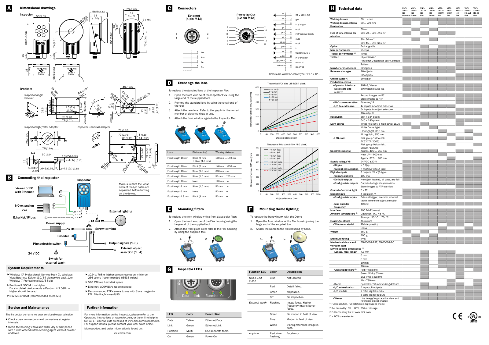
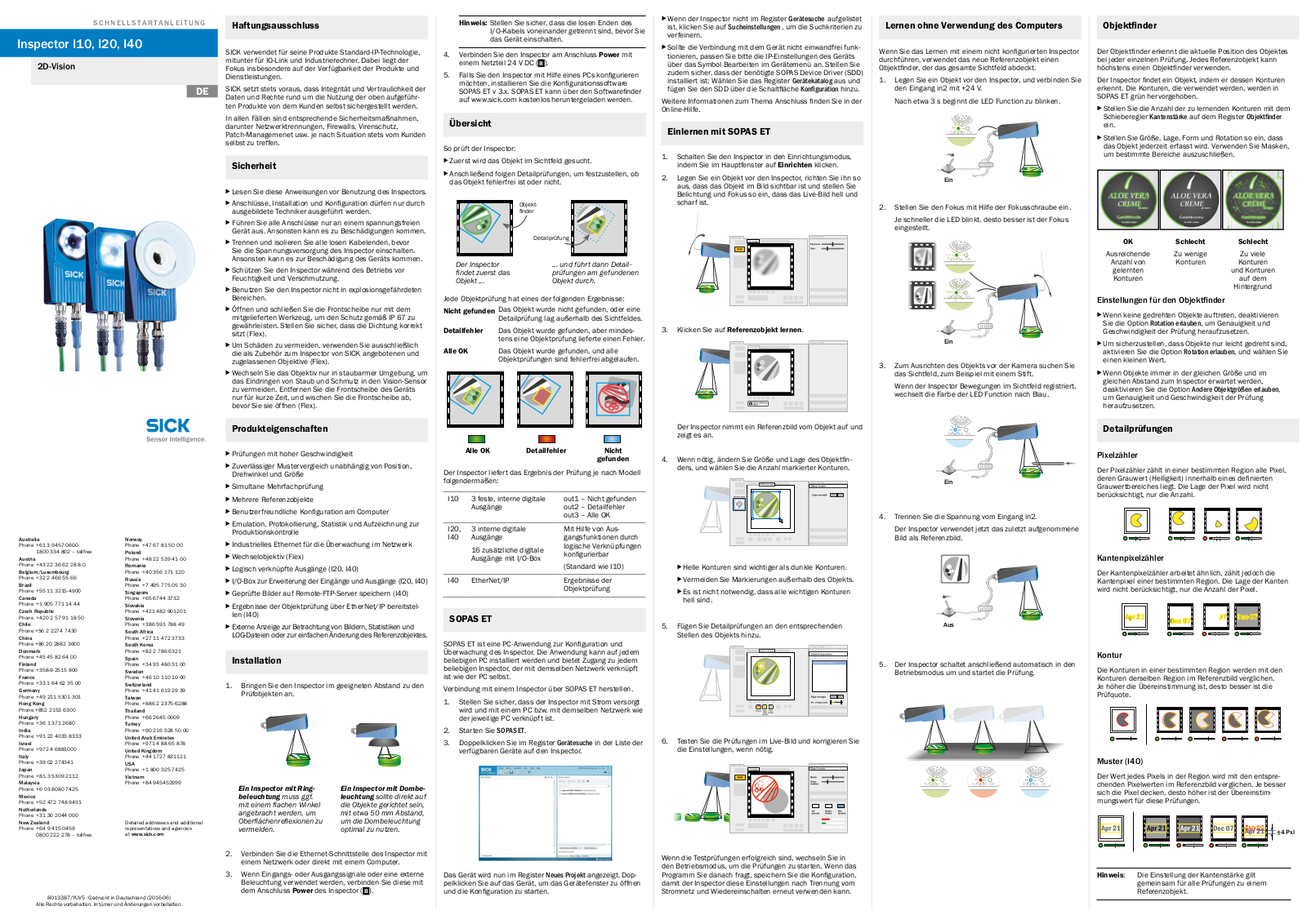
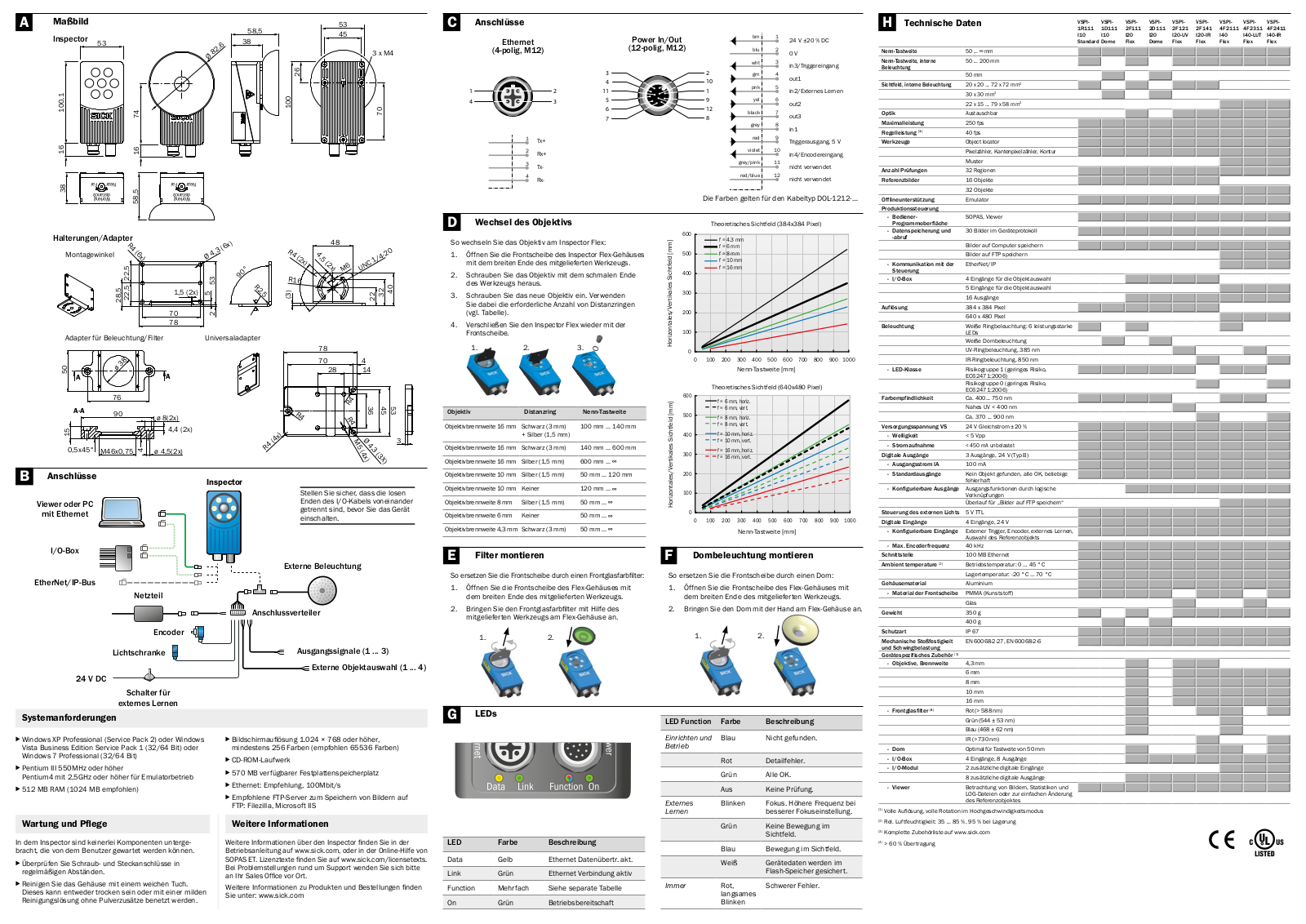


 Loading...