

Page 1
OPERATING INSTRUCTIO
NS
IN4000 Direct
Safety switch
de
en
es
fr
it
Page 2

Inhalt/Contents
Operating instructions
IN4000 Direct
Inhalt/Contents
de Seite 3–48
en Page 49-92
es Página 93–140
fr Page 141–190
it Pagina 191-237
This document is protected by the law of copyright,
whereby all rights established therein remain with the
company SICK AG. Reproduction of this document or
parts of this document is only permissible within the
limits of the legal determination of Copyright Law.
Alteration or abridgement of the document is not
permitted without the explicit written approval of the
company SICK AG.
2 © SICK AG • Germany • All rights reserved 8012183/ZWH0/2018-07-26
Subject to change without notice
Page 3

Betriebsanleitung
de
IN4000 Direct
Inhalt
Inhalt
1 Zu diesem Dokument ..........................................5
1.1 Funktion dieses Dokuments ......................5
1.2 Zielgruppe....................................................5
1.3 Informationstiefe......................................... 6
1.4 Geltungsbereich .......................................... 7
1.5 Verwendete Abkürzungen ..........................7
1.6 Verwendete Symbole ..................................7
2 Zur Sicherheit.......................................................9
2.1 Befähigte Personen ....................................9
2.2 Verwendungsbereiche der
Sicherheitsschalter ...................................10
2.3 Bestimmungsgemäße Verwendung ........11
2.4 Vorhersehbare Fehlanwendung...............11
2.5 Allgemeine Sicherheitshinweise und
Schutzmaßnahmen ..................................12
3 Produktbeschreibung ....................................... 14
3.1 Sicherheitsschalter der Typenreihe
IN4000 Direct............................................14
3.2 Merkmale und Funktionsprinzip..............14
3.3 Freigabezone und sicherer
Ausschaltabstand .....................................15
3.4 LED-Anzeigen.............................................17
3.4.1 Anzeigen im Betriebsmodus ....................17
3.4.2 Anzeigen im Justagemodus .....................18
3.5 Signalverhalten .........................................20
3.6 Manipulationsschutz ................................21
4 Montage............................................................. 22
4.1 Montage des Sicherheitsschalters ..........23
8012183/ZWH0/2018-07-26 © SICK AG • Deutschland • Alle Rechte vorbehalten 3
Irrtümer und Änderungen vorbehalten
Page 4

Inhalt
de
Betriebsanleitung
IN4000 Direct
5 Elektroinstallation und Justage ....................... 27
5.1 Elektroinstallation..................................... 27
5.2 Justage ......................................................29
5.3 Anschlussleitungen ..................................29
5.3.1 Anforderungen an die
Anschlussleitungen ..................................29
5.3.2 Maximale Leitungslänge .......................... 30
5.3.3 Bestimmung der Leitungslänge –
Fallbeispiel ................................................ 31
6 Inbetriebnahme und Betrieb ............................ 32
6.1 Prüfungen vor der
Erstinbetriebnahme.................................. 32
6.1.1 Start-Funktion überprüfen .......................33
6.2 Wiederkehrende technische
Prüfungen.................................................. 34
6.2.1 Tägliche Prüfung.......................................34
6.2.2 Prüfungen durch eine befähigte
Person........................................................34
7 Fehlerdiagnose.................................................. 35
7.1 Sicherheit ..................................................35
7.2 Fehlerbehebung........................................ 36
7.3 Sicherer Zustand im Fehlerfall................37
8 Wartung und Entsorgung ................................. 38
9 Technische Daten.............................................. 39
9.1 Datenblatt .................................................39
9.2 Anschlussbelegung................................... 43
9.3 Maßbild .....................................................44
10 Bestelldaten ...................................................... 45
10.1 Geräte........................................................45
10.2 Zubehör .....................................................45
11 Anhang ............................................................... 46
11.1 Konformität mit EU-Richtlinien................46
11.2 Tabellenverzeichnis ..................................46
11.3 Abbildungsverzeichnis ............................. 48
4 © SICK AG • Deutschland • Alle Rechte vorbehalten 8012183/ZWH0/2018-07-26
Irrtümer und Änderungen vorbehalten
Page 5

Betriebsanleitung Kapitel 1
de
IN4000 Direct
Zu diesem Dokument
1 Zu diesem Dokument
Bitte lesen Sie dieses Kapitel sorgfältig, bevor Sie mit
der Dokumentation und dem IN4000 Direct arbeiten.
1.1 Funktion dieses Dokuments
Diese Betriebsanleitung leitet das technische Personal
des Maschinenherstellers bzw. Maschinenbetreibers
zur sicheren Montage, Parametrierung, Elektroinstallation, Inbetriebnahme sowie zum Betrieb und zur Prüfung des berührungslosen Sicherheitsschalters IN4000
Direct an.
Diese Betriebsanleitung leitet nicht zur Bedienung der
Maschine an, in die der Sicherheitsschalter integriert
ist oder wird. Informationen hierzu enthält die Betriebsanleitung der Maschine.
1.2 Zielgruppe
Diese Betriebsanleitung richtet sich an die Planer,
Entwickler und Betreiber von Anlagen, welche durch
einen oder mehrere berührungslose Sicherheitsschalter IN4000 Direct abgesichert werden sollen. Sie
richtet sich auch an Personen, die den IN4000 Direct
in eine Maschine integrieren, erstmals in Betrieb
nehmen oder prüfen.
8012183/ZWH0/2018-07-26 © SICK AG • Deutschland • Alle Rechte vorbehalten 5
Irrtümer und Änderungen vorbehalten
Page 6

Kapitel 1 Betriebsanleitung
de
Zu diesem Dokument
IN4000 Direct
1.3 Informationstiefe
Diese Betriebsanleitung enthält Informationen über
den berührungslosen Sicherheitsschalter IN4000
Direct zu folgenden Themen:
• Montage
• Elektroinstallation
• Hardware-Inbetriebnahme
• Fehlerdiagnose und Fehlerbehebung
• Artikelnummern
• Konformität und Zulassung
Darüber hinaus sind bei Planung und Einsatz von SICKSchutzeinrichtungen wie dem IN4000 Direct technische Fachkenntnisse notwendig, die nicht in diesem
Dokument vermittelt werden.
Grundsätzlich sind die behördlichen und gesetzlichen
Vorschriften beim Betrieb des berührungslosen Sicherheitsschalters IN4000 Direct einzuhalten.
Allgemeine Informationen zum Thema Sicherheitstechnik enthält die Kompetenzbroschüre „Leitfaden
Sichere Maschinen“.
Hinweis
Nutzen Sie auch die Homepage im Internet unter:
www.sick.com
Dort finden Sie:
• Beispielapplikationen
• Eine Liste häufiger Fragen zum IN4000 Direct
6 © SICK AG • Deutschland • Alle Rechte vorbehalten 8012183/ZWH0/2018-07-26
Irrtümer und Änderungen vorbehalten
Page 7

Betriebsanleitung Kapitel 1
de
IN4000 Direct
Zu diesem Dokument
1.4 Geltungsbereich
Diese Betriebsanleitung ist eine Original-Betriebsanleitung.
Diese Betriebsanleitung ist gültig für den berührungslosen Sicherheitsschalter IN4000 Direct.
1.5 Verwendete Abkürzungen
OSSD
Output signal switching device = Signalausgang, der
den Sicherheitsstromkreis ansteuert
Speicherprogrammierbare Steuerung
SPS
1.6 Verwendete Symbole
Empfehlung
Hinweis
Ν, ∏, ν
= Handeln
Sie …
Empfehlungen geben Ihnen Entscheidungshilfe hinsichtlich der Anwendung einer Funktion oder technischen Maßnahme.
Hinweise informieren Sie über Besonderheiten des
Geräts.
LED-Symbole beschreiben den Zustand einer DiagnoseLED. Beispiele:
Ν Die LED leuchtet konstant.
∏ Die LED blinkt.
ν Die LED ist aus.
Handlungsanweisungen sind durch einen Pfeil gekennzeichnet. Lesen und befolgen Sie Handlungsanweisungen sorgfältig.
ACHTUNG
8012183/ZWH0/2018-07-26 © SICK AG • Deutschland • Alle Rechte vorbehalten 7
Irrtümer und Änderungen vorbehalten
Warnhinweis!
Ein Warnhinweis weist Sie auf konkrete oder potentielle Gefahren hin. Dies soll Sie vor Unfällen bewahren.
⋅ Lesen und befolgen Sie Warnhinweise sorgfältig!
Page 8

Kapitel 1 Betriebsanleitung
de
Zu diesem Dokument
IN4000 Direct
Der Begriff „Gefahr bringender Zustand“
In den Abbildungen in diesem Dokument wird der
Gefahr bringende Zustand (Normbegriff) der Maschine
stets als Bewegung eines Maschinenteils dargestellt. In
der Praxis kann es verschiedene Gefahr bringende
Zustände geben:
• Maschinenbewegungen
• Strom führende Teile
• Sichtbare oder unsichtbare Strahlung
• Eine Kombination mehrerer Gefahren
8 © SICK AG • Deutschland • Alle Rechte vorbehalten 8012183/ZWH0/2018-07-26
Irrtümer und Änderungen vorbehalten
Page 9

Betriebsanleitung Kapitel 2
de
IN4000 Direct
Zur Sicherheit
2 Zur Sicherheit
Dieses Kapitel dient Ihrer Sicherheit und der Sicherheit
der Anlagenbenutzer.
⋅ Bitte lesen Sie dieses Kapitel sorgfältig, bevor Sie
mit den induktiven Sicherheitsschaltern der Typenreihe IN4000 Direct oder der durch diese Sicherheitsschalter in Verbindung mit den entsprechenden
Schutzeinrichtungen geschützten Maschine
arbeiten.
Für Einbau und Verwendung der Sicherheitsschalter
der Typenreihe IN4000 Direct sowie für Inbetriebnahme und wiederkehrende technische Überprüfungen
gelten die nationalen/internationalen Rechtsvorschriften, insbesondere:
• die Maschinenrichtlinie
• die EMV-Richtlinie
• die Arbeitsmittelbenutzungsrichtlinie
• die Sicherheitsvorschriften
sowie
• die Unfallverhütungsvorschriften/Sicherheitsregeln
2.1 Befähigte Personen
Die Sicherheitsschalter der Typenreihe IN4000 Direct
dürfen nur von befähigten Personen montiert und in
Betrieb genommen werden. Befähigt ist, wer
• über eine geeignete technische Ausbildung verfügt
und
• vom Maschinenbetreiber in der Bedienung und den
gültigen Sicherheitsrichtlinien unterwiesen wurde
und
• Zugriff auf diese Betriebsanleitung hat.
8012183/ZWH0/2018-07-26 © SICK AG • Deutschland • Alle Rechte vorbehalten 9
Irrtümer und Änderungen vorbehalten
Page 10

Kapitel 2 Betriebsanleitung
de
Zur Sicherheit
IN4000 Direct
2.2 Verwendungsbereiche der Sicherheitsschalter
Die Sicherheitsschalter der Typenreihe IN4000 Direct
sind induktive Sensoren, die berührungslos durch
Metall betätigt werden. Der sichere Zustand ist der
stromlose Zustand (logisch „0“ eines OSSDs).
Mit den Sicherheitsschaltern der Typenreihe IN4000
Direct und der entsprechenden Maschinen- oder
Anlagensteuerung können Positionen von beweglichen
Maschinen oder Maschinenteilen so abgesichert
werden, dass …
• der Gefahr bringende Zustand der Maschine oder
Anlage nur dann eingeschaltet werden kann, wenn
sich diese in sicherer Position befinden.
• ein Stopp-Befehl ausgelöst wird, wenn bei laufender
Maschine der sichere Bereich oder die sichere
Position verlassen wird.
Für die Steuerung bedeutet dies, dass …
• Einschaltbefehle, die Gefahr bringende Zustände
hervorrufen, erst dann wirksam werden dürfen,
wenn sich die beweglichen Maschinenteile in
sicherer Position befinden,
und
• Gefahr bringende Zustände beendet sein müssen,
bevor die Schutzstellung aufgehoben ist.
Vor dem Einsatz der Sicherheitsschalter ist eine Risikobeurteilung an der Maschine durchzuführen.
Zur bestimmungsgemäßen Verwendung gehört auch
das Einhalten der einschlägigen Anforderungen für den
Einbau und den Betrieb.
Die Sicherheitsschalter müssen regelmäßig einer
technischen Überprüfung unterzogen werden (siehe
Abschnitt 6.2 auf Seite 34).
10 © SICK AG • Deutschland • Alle Rechte vorbehalten 8012183/ZWH0/2018-07-26
Irrtümer und Änderungen vorbehalten
Page 11

Betriebsanleitung Kapitel 2
de
IN4000 Direct
Zur Sicherheit
2.3 Bestimmungsgemäße Verwendung
Die Sicherheitsschalter der Typenreihe IN4000 Direct
dürfen nur im Sinne von Abschnitt 2.2 „Verwendungsbereiche der Sicherheitsschalter“ auf Seite 10 verwendet werden. Die Sicherheitsschalter dürfen nur von befähigten Personen installiert und nur an der Maschine
verwendet werden, an der sie gemäß dieser Betriebsanleitung von einer befähigten Person installiert und
erstmalig in Betrieb genommen wurden.
Der Sicherheitsschalter darf zu jeder Zeit nur innerhalb
der Grenzen der vorgeschriebenen und angegebenen
technischen Daten und Betriebsbedingungen verwendet werden.
Bei jeder anderen Verwendung sowie bei Veränderungen an den Geräten – auch im Rahmen von Montage
und Installation – verfällt jeglicher Gewährleistungsanspruch gegenüber der SICK AG.
2.4 Vorhersehbare Fehlanwendung
Der Sicherheitsschalter ist unter anderem für nachfolgende Verwendungen nicht geeignet:
• In der Umgebung von chemischen und biologischen
Medien (fest, flüssig, gasförmig)
• In Umgebungen mit erhöhter ionisierender Strahlung
8012183/ZWH0/2018-07-26 © SICK AG • Deutschland • Alle Rechte vorbehalten 11
Irrtümer und Änderungen vorbehalten
Page 12

Kapitel 2 Betriebsanleitung
de
Zur Sicherheit
IN4000 Direct
2.5 Allgemeine Sicherheitshinweise und Schutzmaßnahmen
Der Sicherheitsschalter IN4000 Direct erfüllt eine Personenschutzfunktion. Unsachgemäßer Einbau oder
Manipulationen können zu schweren Verletzungen von
Personen führen.
Der Sicherheitsschalter IN4000 Direct erfüllt folgende
Sicherheitsanforderungen:
• SIL3 gemäß IEC 61 508,
• SILCL3 gemäß EN 62 061,
• Performance Level e gemäß EN ISO 13 849-1
(applikationsabhängig).
Änderungshinweis
• Für Geräte bis KW24 2018 gilt:
PFHD 2,5 × 10⁻⁹/Kategorie 4 (EN ISO 13 849-1)
• Für Geräte ab KW25 2018 gilt:
PFHD 1,0 × 10⁻⁸/Kategorie 3 (EN ISO 13 849-1)
⋅ Prüfen Sie, ob das Gerät den gewünschten Sicher-
heitsanforderungen der Applikation entspricht.
Hinweis zur Klassifizierung des Geräts gemäß
EN 60 947-5-2:
• Der Sicherheitsschalter IN40-E0101K entspricht in
Abhängigkeit von der Einbauart der Klassifizierung
I1C40SP2M bzw. I2C40SP2M.
• Der Sicherheitsschalter IN40-E0109K entspricht in
Abhängigkeit von der Einbauart der Klassifizierung
I2C40SP2M.
12 © SICK AG • Deutschland • Alle Rechte vorbehalten 8012183/ZWH0/2018-07-26
Irrtümer und Änderungen vorbehalten
Page 13

Betriebsanleitung Kapitel 2
de
IN4000 Direct
ACHTUNG
Zur Sicherheit
Sicherheitsschalter dürfen nicht umgangen, weggedreht, entfernt oder auf andere Weise unwirksam
gemacht werden. Die Ausgänge dürfen nicht überbrückt werden.
Die induktiven Sicherheitsschalter reagieren auf
metallische Gegenstände. Andere metallische
Gegenstände, die die Sicherheitsfunktion nicht
auslösen sollen, dürfen keinesfalls auf die aktive
Fläche der Sicherheitsschalter aufgebracht werden.
Deshalb müssen geeignete Maßnahmen getroffen
werden, die das verhindern.
Bitte beachten Sie die Einbaumaßnahmen gemäß
EN ISO 14 119.
Beschädigte Geräte müssen ausgetauscht werden.
8012183/ZWH0/2018-07-26 © SICK AG • Deutschland • Alle Rechte vorbehalten 13
Irrtümer und Änderungen vorbehalten
Page 14

Kapitel 3 Betriebsanleitung
de
Produktbeschreibung
IN4000 Direct
3 Produktbeschreibung
3.1 Sicherheitsschalter der Typenreihe IN4000 Direct
Der Sicherheitsschalter verfügt über ein quaderförmiges Gehäuse mit ausrichtbarer aktiver Sensorfläche. Die Klassifizierung gemäß EN 60 947-5-2 hängt
von der Montageart ab (siehe Tab. 5 auf Seite 23).
3.2 Merkmale und Funktionsprinzip
Die Sicherheitsschalter der Typenreihe IN4000 Direct
werden typischerweise für eine sichere Positionserkennung eingesetzt. Der Sensor detektiert die Anbzw. Abwesenheit von Metall. Um den Anforderungen
gegen einfache Manipulation nachzukommen, wird der
Schaltbereich des Sensors zeitlich und räumlich
überwacht.
Mittels LEDs kann der Status direkt am Sensor abgelesen werden. Fehler, wie beispielsweise Spulenbruch,
Kurzschluss und Leitungsbruch, werden durch die
Selbstüberwachung des Sensors erkannt.
Der Sicherheitsschalter kann direkt an eine
fehlersichere SPS oder an eine andere sichere
Auswerteeinheit angeschlossen werden.
14 © SICK AG • Deutschland • Alle Rechte vorbehalten 8012183/ZWH0/2018-07-26
Irrtümer und Änderungen vorbehalten
Page 15
Betriebsanleitung Kapitel 3
de
Ausschaltabstand
IN4000 Direct
Produktbeschreibung
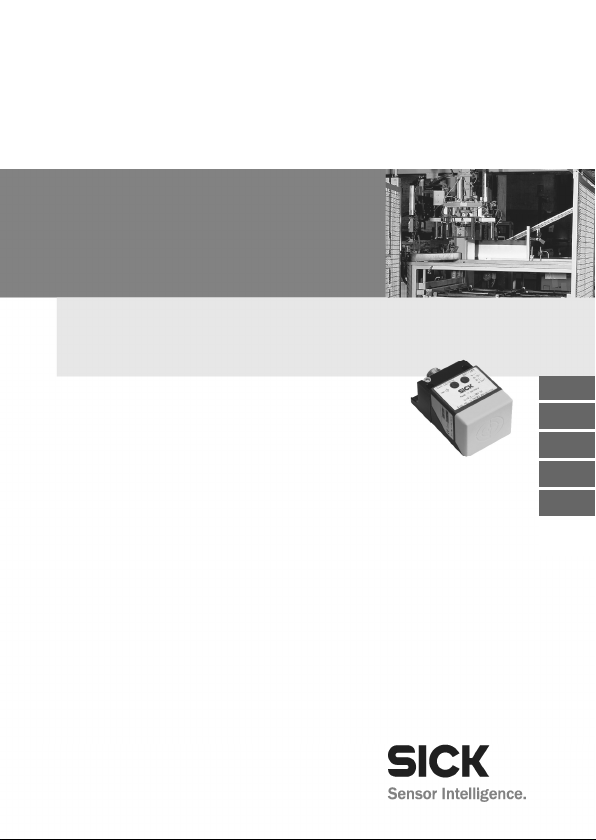
3.3 Freigabezone und sicherer Ausschaltabstand
Abb. 1: Schematische Abbildung
der Zonen der
Sicherheitsschalter IN4000
Direct
Nahbereich
Sensor
Freigabezone
Bedämpfungsobjekt
(Metall)
8012183/ZWH0/2018-07-26 © SICK AG • Deutschland • Alle Rechte vorbehalten 15
Irrtümer und Änderungen vorbehalten
Sicherer
Distanz
Der Ausgang des Sicherheitsschalters wird nur bei
einer Bedämpfung innerhalb der Freigabezone freigegeben. Außerhalb der Freigabezone, also auch im
Nahbereich, bleibt der Ausgang ausgeschaltet.
Nach einer Bedämpfung im Nahbereich muss entweder
die Versorgungsspannung unterbrochen oder das
Bedämpfungselement für mehr als 2 s in den sicheren
Ausschaltabstand gebracht werden, bevor wieder die
Freigabe erfolgen kann.
Die Freigabezone ist abhängig von Material und Form
des Bedämpfungselements. Die Verwendung anderer
Bedämpfungselemente (Material, Form) ergibt eine
andere Freigabezone.
Typischerweise werden bei einer Umgebungstemperatur von 20 °C bei nicht-bündigem Einbau des Sicherheitsschalters mit einer Normplatte gemäß
EN 60 947-5-2 (IN40-E0101K: 45 × 45 × 1 mm³,
IN40-E0109K: 60 × 60 × 1 mm³) mit verschiedenen
Materialien folgende Freigabezonen erreicht:
Page 16

Kapitel 3 Betriebsanleitung
de
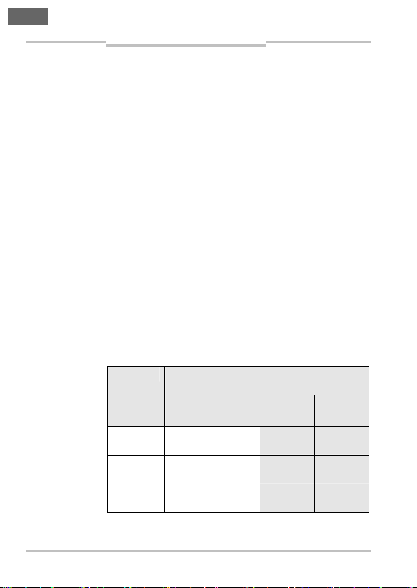
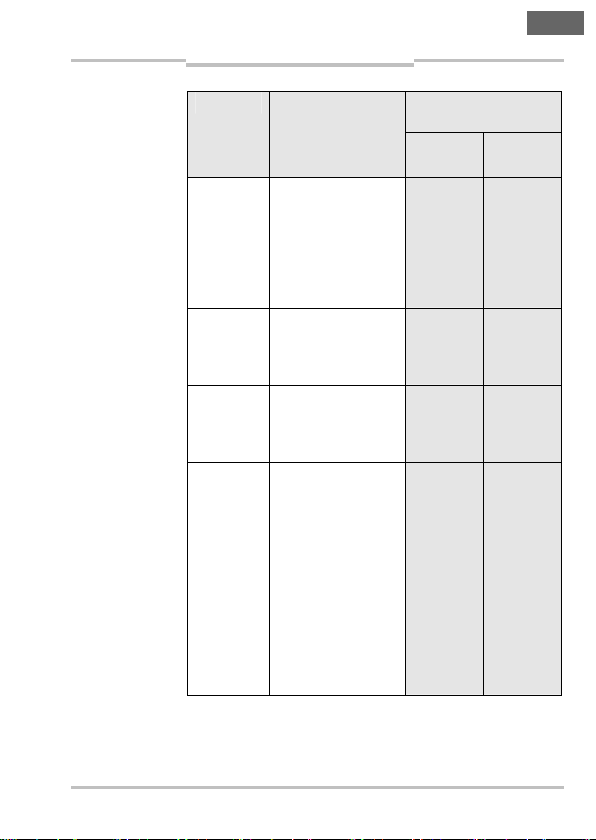
Tab. 1: Freigabezone und sicherer
Ausschaltabstand
IN40-E0101K
Produktbeschreibung
IN40-E0101K
FreigabezoneMaterial
Untere
Grenze
Obere
Grenze
IN4000 Direct
Sicherer
Ausschalt-
abstand
Stahl FE360 10,0 mm 15,0 mm
Edelstahl
7,5 mm 13,2 mm
1.4302 (V2A)
AlMg 3G22 2,0 mm 5,8 mm
30 mm
Al 99 % 1,4 mm 5,0 mm
CuZn 37 2,3 mm 6,2 mm
Cu 0,8 mm 4,3 mm
Tab. 2: Freigabezone und sicherer
Ausschaltabstand
IN40-E0109K
IN40-E0109K
FreigabezoneMaterial
Untere
Grenze
Obere
Grenze
Sicherer
Ausschalt-
abstand
Stahl FE360 4,0 mm 20,0 mm
Edelstahl
2,0 mm 17,6 mm
1.4302 (V2A)
AlMg 3G22 0,0 mm 9,6 mm
45 mm
Al 99 % 0,0 mm 8,6 mm
CuZn 37 0,0 mm 10,0 mm
Cu 0,0 mm 7,0 mm
16 © SICK AG • Deutschland • Alle Rechte vorbehalten 8012183/ZWH0/2018-07-26
Irrtümer und Änderungen vorbehalten
Page 17
Betriebsanleitung Kapitel 3
de
grün
gelb
IN4000 Direct
Produktbeschreibung
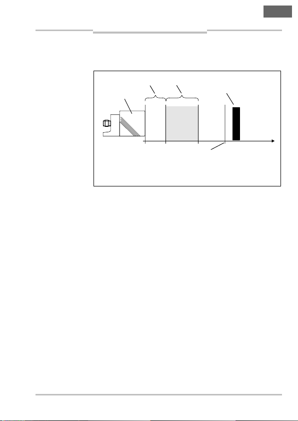
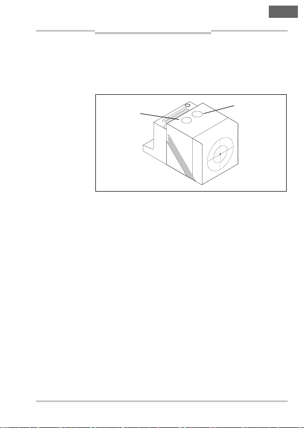
3.4 LED-Anzeigen
Die Sicherheitsschalter besitzen zwei LEDs, die den
Status der Versorgungsspannung und den Betriebszustand anzeigen.
Abb. 2: LEDAnzeigen für
Versorgungsspannung und
Betriebszustand
Hinweis
LED Power,
3.4.1 Anzeigen im Betriebsmodus
Die gelbe Signal-LED leuchtet je nach Dauer der vorhergehenden Entdämpfung sofort oder zeitverzögert,
wenn ein Bedämpfungsobjekt in die Freigabezone
gelangt.
Unabhängig vom Verhalten der gelben Signal-LED
schaltet der Ausgang in jedem Fall mit den normalen
Reaktionszeiten (siehe Abschnitt 9.1 auf Seite 42)
ohne zusätzliche Verzögerung.
• Wenn sich das Bedämpfungselement bei Einschalten der Versorgungsspannung in der Freigabezone
(vgl. Tab. 1 auf Seite 16) befindet, schaltet die gelbe
Signal-LED mit einer Zeitverzögerung von 5 s.
• War das Bedämpfungselement ≥ 2 s im sicheren
Ausschaltabstand (vgl. Tab. 1 auf Seite 16) vom
Sensor entfernt und wird dann wieder in die
Freigabezone gebracht, schaltet die gelbe SignalLED mit einer Verzögerung von 3 s.
LED Signal,
8012183/ZWH0/2018-07-26 © SICK AG • Deutschland • Alle Rechte vorbehalten 17
Irrtümer und Änderungen vorbehalten
Page 18
Kapitel 3 Betriebsanleitung
de
Produktbeschreibung
IN4000 Direct
• War das Bedämpfungselement < 2 s im sicheren
Ausschaltabstand (vgl. Tab. 1 auf Seite 16) vom
Sensor entfernt und wird dann wieder in die
Freigabezone gebracht, schaltet die gelbe SignalLED ohne Zeitverzögerung.
• Wird das Bedämpfungselement in den sicheren
Ausschaltabstand (vgl. Tab. 1 auf Seite 16) vom
Sensor gebracht, schaltet die gelbe Signal-LED ohne
Verzögerung ab.
• Wird das Bedämpfungselement in den Nahbereich
(vgl. Tab. 1 auf Seite 16) gebracht, schaltet die gelbe
Signal-LED mit einer Verzögerung von 2 s ab.
3.4.2 Anzeigen im Justagemodus
Im Justagemodus (siehe Abschnitt 5.2 auf Seite 29)
• blinkt die gelbe Signal-LED, wenn sich das Bedämpfungselement außerhalb der Freigabezone befindet,
• erlischt die gelbe Signal-LED, wenn sich das
Bedämpfungselement innerhalb der Freigabezone
oder im sicheren Ausschaltbereich befindet.
Hinweis
Im Justagemodus bleibt der Ausgang im sicheren
Zustand.
Tab. 3: Betriebsanzeigen des
IN4000 Direct im
Justagemodus
Ν Die LED
leuchtet
konstant.
∏ Die LED
blinkt.
⌠∏ Die LED
blinkt
schnell.
ν Die LED
ist aus.
Anzeige Bedeutung
ν Gelb
ν Grün
ν Gelb
Keine Versorgungsspannung
Unterspannung 0 0
∏ Grün
ν Gelb
Überspannung
⌠∏ Grün
Schaltzustand der
Ausgänge
OUT1
(OSSD1)
(OSSD2)
0 0
0 0
OUT2
18 © SICK AG • Deutschland • Alle Rechte vorbehalten 8012183/ZWH0/2018-07-26
Irrtümer und Änderungen vorbehalten
Page 19
Betriebsanleitung Kapitel 3
de
IN4000 Direct
Produktbeschreibung
Anzeige Bedeutung
Schaltzustand der
Ausgänge
ν Gelb
Ν Grün
Ausgang ausgeschaltet; außerhalb
OUT1
(OSSD1)
0 0
OUT2
(OSSD2)
der Freigabezone
(Betriebsmodus)
oder innerhalb der
Freigabezone
(Justagemodus)
Ν Gelb
Ν Grün
Ausgang geschaltet;
innerhalb der
1 1
Freigabezone
(Betriebsmodus)
∏ Gelb
Ν Grün
Ausgang ausgeschaltet; außerhalb
0 0
der Freigabezone
(Justagemodus)
∏ Gelb
ν Grün
Interner oder
externer Fehler:
• z. B. Querschluss
0
0
0
1
zwischen den
Ausgängen
• z. B. Kurzschluss
1
0
eines Ausgangs
mit Versorgung
oder Masse
(siehe Abschnitt 7.2
„Fehlerbehebung“
auf Seite 36)
8012183/ZWH0/2018-07-26 © SICK AG • Deutschland • Alle Rechte vorbehalten 19
Irrtümer und Änderungen vorbehalten
Page 20
Kapitel 3 Betriebsanleitung
de
Produktbeschreibung
IN4000 Direct
3.5 Signalverhalten
Der sichere Zustand ist der ausgeschaltete Zustand
(stromloser Zustand: logisch „0“ eines OSSDs).
Ist das Bedämpfungselement in der Freigabezone und
liegt kein Sensorfehler vor, werden beide Ausgangsstufen (OSSD) durchgeschaltet (logisch „1“).
Die Ausgangskenndaten sind kompatibel zu den
Kenndaten des Eingangs gemäß EN 61 131-2 Typ 1
oder 2:
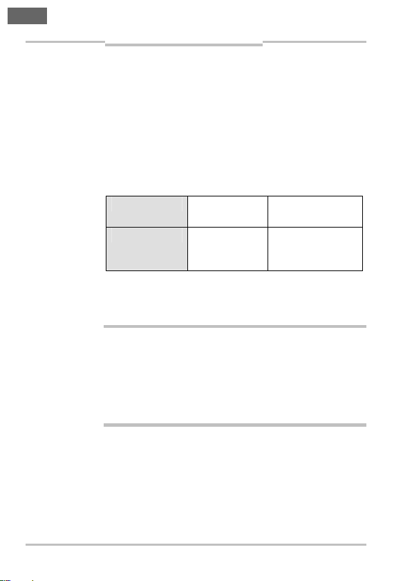
Tab. 4: Ausgangskenndaten der
Sicherheitsschalter IN4000
Direct
ACHTUNG
Logisch „1“ ≥ 15 V
≥ 11 V
Logisch „0“ ≤ 5 V Reststrom 0,2 mA
Ist das Bedämpfungselement außerhalb der Freigabezone, werden die Ausgänge abgeschaltet (logisch „0“;
sicherer Zustand).
Querschlüsse zwischen beiden Ausgängen werden
vom Sicherheitsschalter erkannt und führen zur
Abschaltung der Ausgänge (OSSD).
Querschlüsse zwischen der Versorgungsspannung
und einem Ausgang werden erkannt und führen zur
Abschaltung des anderen Ausgangs.
2 … 15 mA
15 … 30 mA
Pull-down-Strom
typ. 30 mA
20 © SICK AG • Deutschland • Alle Rechte vorbehalten 8012183/ZWH0/2018-07-26
Irrtümer und Änderungen vorbehalten
Page 21

Betriebsanleitung Kapitel 3
de
IN4000 Direct
Produktbeschreibung
3.6 Manipulationsschutz
Die induktiven Sicherheitsschalter reagieren auf
ACHTUNG
metallische Gegenstände. Andere metallische
Gegenstände, die die Sicherheitsfunktion nicht
auslösen sollen, dürfen keinesfalls auf die aktive
Fläche der Sicherheitsschalter gelangen. Deshalb
müssen geeignete Maßnahmen getroffen werden,
um dies zu verhindern.
Der Sicherheitsschalter ist durch das folgende Schaltverhalten gegen einfaches Umgehen gesichert:
• Durch langsame Annäherung eines metallischen
Gegenstandes in die Freigabezone wird der Ausgang
unverzüglich angesteuert, aber durch die Signal-LED
erst mit einer Zeitverzögerung von ca. 3 s angezeigt.
Dadurch befindet sich der Gegenstand in der Regel
in der Nahbereichszone, bevor die Signal-LED
leuchtet. Die technischen Vorschriften hinsichtlich
des Wiederanlaufs der Anlage sind zu beachten.
• Bleibt dieser Gegenstand länger als ca. 2 s in der
Nahbereichszone, wird der Ausgang komplett gesperrt und bei einer Bedämpfung in der Freigabezone nicht mehr freigegeben. Bleibt der Gegenstand
länger als ca. 5 s in der Nahbereichszone, wird der
Justagemodus aktiviert (siehe Abschnitt 5.2 auf
Seite 29).
Die Entsperrung der Freigabezone kann entweder
erfolgen
• durch Entdämpfen
(IN40-E0101K: > 30 mm, IN40-E0109K: > 45 mm)
für eine Zeit von mehr als 2 s
oder
• durch eine Spannungsunterbrechung (siehe
Abschnitt 5.2 auf Seite 29).
8012183/ZWH0/2018-07-26 © SICK AG • Deutschland • Alle Rechte vorbehalten 21
Irrtümer und Änderungen vorbehalten
Page 22

Kapitel 4 Betriebsanleitung
de
Montage
IN4000 Direct
4 Montage
Der Sicherheitsschalter IN4000 Direct darf nur von
ACHTUNG
ACHTUNG
GEFAHR
autorisiertem Fachpersonal montiert werden.
Den Montageort und die Montageposition des Sicherheitsschalters so auswählen, dass
• der Sicherheitsschalter für Bedienpersonal bei
geöffneter Schutzeinrichtung schwer zugänglich ist,
• Kontrolle und Austausch des Sicherheitsschalters
möglich ist.
Eine Umgehung des induktiven Sicherheitsschalters
auf einfache Weise oder eine unbeabsichtigte Betätigung muss gemäß EN ISO 14 119 durch geeignete
Einbaumaßnahmen verhindert werden.
Beschädigung des Sicherheitsschalters durch
mechanische Belastung
Verlust der Sicherheitsfunktion
⋅ Sicherheitsschalter vor mechanischer Belastung wie
Schlägen oder permanentem Anpressdruck
schützen, z. B. durch zusätzlichen Anschlag.
22 © SICK AG • Deutschland • Alle Rechte vorbehalten 8012183/ZWH0/2018-07-26
Irrtümer und Änderungen vorbehalten
Page 23
Betriebsanleitung Kapitel 4
de
IN4000 Direct
Montage
4.1 Montage des Sicherheitsschalters
Beachten Sie die vorgeschriebene Montageart und
ACHTUNG
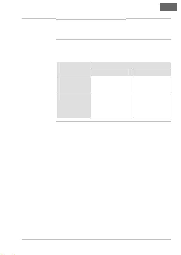
Tab. 5: Zulässige
Montagearten und
resultierende Klassifizierung gemäß
EN 60
947-5-2
die resultierende Klassifizierung gemäß
EN 60 947-5-2!
Material
Kupfer,
Aluminium,
Messing
Stahl Einseitig bündig
Zulässige MontageartenUmgebendes
IN40-E0101K IN40-E0109K
Bündig
φ I1C40SP2
oder
nicht-bündig
φ I2C40SP2
Nicht-bündig
φ I2C40SP2
8012183/ZWH0/2018-07-26 © SICK AG • Deutschland • Alle Rechte vorbehalten 23
Irrtümer und Änderungen vorbehalten
Page 24
Kapitel 4 Betriebsanleitung
de
Montage
IN4000 Direct
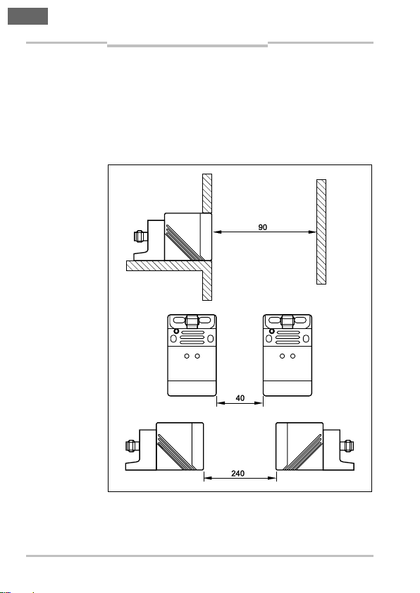
• Sicheren Ausschaltabstand und Freigabezone
beachten (vgl. Tab. 1 auf Seite 16).
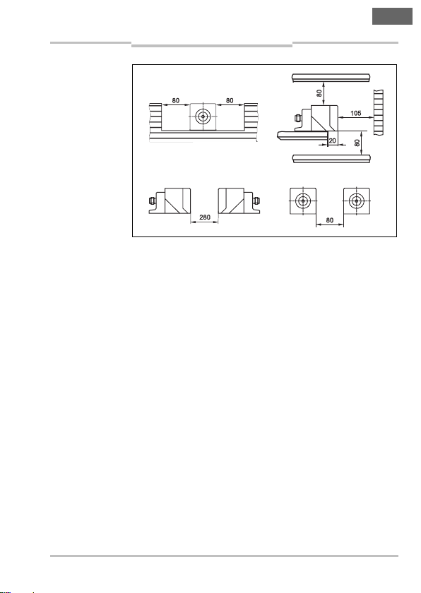
• Die in Abb. 3 (IN40-E0101K) bzw. Abb. 4
(IN40-E0109K) genannten Mindestabstände für
benachbarte und gegenüberliegende Sensoren und
die Mindestabstände zu feststehenden Anlagenteilen und Wänden müssen eingehalten werden.
Abb. 3: Mindestabstände bei der
Montage des
Sicherheitsschalters
IN40-E0101K
24 © SICK AG • Deutschland • Alle Rechte vorbehalten 8012183/ZWH0/2018-07-26
Irrtümer und Änderungen vorbehalten
Page 25
Betriebsanleitung Kapitel 4
de
IN4000 Direct
Abb. 4: Mindestabstände bei der
Montage des
Sicherheitsschalters
IN40-E0109K
Montage
• Der Sicherheitsschalter muss so montiert werden,
dass die aktive Fläche des Sensors zum beweglichen Teil der Schutzeinrichtung (Tür o. ä.) orientiert
ist. Die aktive Fläche kann bei Bedarf ausgerichtet
werden.
• Der Sicherheitsschalter wird vormontiert auf einem
Haltewinkel ausgeliefert. Zur Ausrichtung der aktiven
Fläche des Sensors muss der Haltewinkel nicht demontiert werden.
Die aktive Fläche des Sicherheitsschalters so ausrichten, dass sie nach der Montage zum beweglichen
Teil der Schutzeinrichtung orientiert ist.
So richten Sie den Sicherheitsschalter aus:
⋅ Die Innensechskantschraube am Sensorhalter
öffnen und den Sensor vom Halter abziehen
(vgl. Abb. 5 a–b).
⋅ Die beiden Schrauben an der unteren Ecke des
Sensorgehäuses lösen und die aktive Sensorfläche
in die richtige Position drehen (vgl. Abb. 5 c–d).
⋅ Das Sensorgehäuse wieder verschrauben und den
Sensor wieder am Sensorhalter montieren
(vgl. Abb. 5 e–f).
8012183/ZWH0/2018-07-26 © SICK AG • Deutschland • Alle Rechte vorbehalten 25
Irrtümer und Änderungen vorbehalten
Page 26

Kapitel 4 Betriebsanleitung
de
Abb. 5: Ausrichtung der aktiven
Sensorfläche des
Sicherheitsschalters
Montage
IN4000 Direct
a b
dc
e f
⋅ Den Sicherheitsschalter mithilfe des Haltewinkels
möglichst unlösbar am ausgewählten Montageort
und in der gewählten Position befestigen. Unlösbare
Schrauben mit 1,0 Nm anziehen.
26 © SICK AG • Deutschland • Alle Rechte vorbehalten 8012183/ZWH0/2018-07-26
Irrtümer und Änderungen vorbehalten
Page 27

Elektroinstallation und
de
Betriebsanleitung Kapitel 5
IN4000 Direct
Justage
5 Elektroinstallation und Justage
5.1 Elektroinstallation
Die Versorgungsspannung (L+ … L–) ist zwischen Pin 1
und Pin 3 des Steckers anzuschließen (vgl. Abschnitt
9.2 auf Seite 43). Die Nennspannung beträgt 24 V DC.
Diese Spannung darf entsprechend EN 61 131-2
zwischen 19,2 V und 30 V bei 5 % Restwelligkeit
schwanken.
Die Versorgungsspannung muss SELV gemäß
ACHTUNG
EN 60 950-1 entsprechen.
Für den Einsatz und die Verwendung gemäß den Anforderungen von cULus muss die Versorgungsspannung
von einem sekundär abgesicherten Transformator
bereitgestellt werden:
a) entweder max. 5 A für Spannungen von 0 … 20 Vrms
(0 … 28,3 Vp)
b) oder 100/Vp für Spannungen von 20 … 30 Vrms
(28,3 … 42,4 Vp).
Es ist ein sicheres industrielles Netzteil mit Überspannungsschutz zu verwenden. Im Fehlerfall dürfen
60 V DC nicht überschritten werden.
8012183/ZWH0/2018-07-26 © SICK AG • Deutschland • Alle Rechte vorbehalten 27
Irrtümer und Änderungen vorbehalten
Page 28

Elektroinstallation und
de
OSSD1
Sicherheitsausgang1OSSD2
Sicherheitsausgang2
OSSD1
Sicherheitsausgang1
OSSD2
Sicherheitsausgang2
Kapitel 5 Betriebsanleitung
ACHTUNG
Justage
IN4000 Direct
Verhindern Sie, dass zwischen Last und Schutzeinrichtung eine Potenzialdifferenz entstehen kann!
⋅ Wenn Sie an den OSSDs bzw. Sicherheitsausgängen
Lasten anschließen, die nicht verpolungssicher sind,
dann müssen Sie die 0-V-Anschlüsse dieser Lasten
und die der zugehörigen Schutzeinrichtung einzeln
und unmittelbar an dieselbe 0-V-Klemmleiste
anschließen. Nur so ist sichergestellt, dass im
Fehlerfall keine Potenzialdifferenz zwischen den
0-V-Anschlüssen der Lasten und denen der zugehörigen Schutzeinrichtung möglich ist.
28 © SICK AG • Deutschland • Alle Rechte vorbehalten 8012183/ZWH0/2018-07-26
Irrtümer und Änderungen vorbehalten
Page 29
Elektroinstallation und
de
Betriebsanleitung Kapitel 5
IN4000 Direct
Justage
5.2 Justage
Um eine geeignete Montageposition zu ermitteln, kann
der Sensor in einen Justagemodus gebracht werden.
⋅ Metallischen Gegenstand für etwa 5 s in den Nah-
bereich (vgl. Abb. 1 auf Seite 15 und Tab. 1 auf
Seite 16) des Sensors halten; wenn die gelbe SignalLED blinkt, ist der Sensor im Justagemodus.
Hinweis
Im Justagemodus bleibt der Ausgang im sicheren
Zustand.
⋅ Zur Ermittlung der Freigabezone Bedämpfungs-
element vor den Sensor bewegen; die gelbe SignalLED geht aus, wenn sich das Bedämpfungselement
in der Freigabezone befindet.
⋅ Sensor und Bedämpfungselement in der gefunde-
nen Position fest montieren.
⋅ Justagemodus durch Spannungsunterbrechung oder
Entdämpfen des Sensors für mehr als 2 s wieder
ausschalten.
5.3 Anschlussleitungen
5.3.1 Anforderungen an die Anschlussleitungen
Durch falsche Bemessung der Anschlussleitungen
kann es zu einem Ausfall der Sicherheitsfunktion kommen. Verwenden Sie möglichst Anschlussbauteile und
Anschlussleitungen der SICK AG. Die Anschlussleitungen müssen die folgenden Bedingungen erfüllen:
Tab. 6: Geeignete
Anschlussleitungen der Sicherheitsschalter
IN4000 Direct
Aderquerschnitt min. 0,34 mm²
R max. 60 Ω/km
C max. 120 nF/km
L max. 0,65 mH/km
Empfohlener Leitungstyp LIYY 8 × bzw. 5 × 0,34 mm²
Wert
8012183/ZWH0/2018-07-26 © SICK AG • Deutschland • Alle Rechte vorbehalten 29
Irrtümer und Änderungen vorbehalten
Page 30
Elektroinstallation und
de
Kapitel 5 Betriebsanleitung
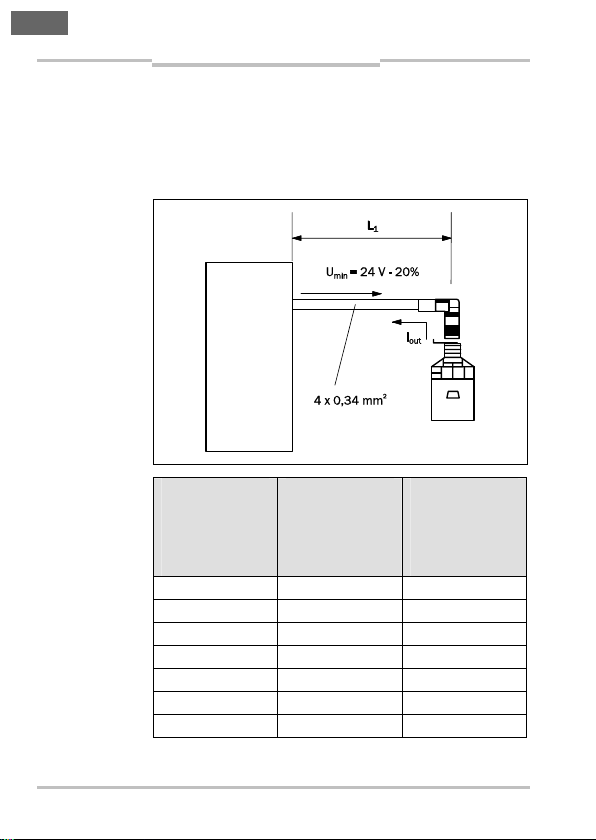
Abb. 6: Maximale
Leitungslänge
Justage
IN4000 Direct
5.3.2 Maximale Leitungslänge
Unter Berücksichtigung des spezifizierten Leitungswiderstandes sind folgende Leitungslängen in Abhängigkeit des Ausgangsstromes I
(siehe Tab. 7).
pro Kanal zulässig
out
SPS
Tab. 7: Maximale
Leitungslänge
I
[mA]
out
Möglicher
Ausgangsstrom
pro Kanal
OUT1/OUT2
L1 [m]
Maximale
Leitungslänge
(siehe Abschnitt
5.3.1, Seite 29)
widerstand
20 65 6,4
30 45 4,4
40 30 3,2
50 25 2,6
70 18 1,8
90 15 1,4
100 12 1,3
30 © SICK AG • Deutschland • Alle Rechte vorbehalten 8012183/ZWH0/2018-07-26
Irrtümer und Änderungen vorbehalten
R
[Ω]
max
Maximal
zulässiger
Leitungs-
Page 31

Elektroinstallation und
de
Betriebsanleitung Kapitel 5
IN4000 Direct
ACHTUNG
Justage
Begrenzen Sie die Leitungslänge und den Leitungswiderstand zur nachgeschalteten Sicherheitsauswertung auf die durch Tab. 7 auf Seite 30 ermittelte
maximale Leitungslänge L1 und maximalen
Leitungswiderstand R
zwischen den Ausgängen sicher erkannt wird.
, damit ein Querschluss
max
5.3.3 Bestimmung der Leitungslänge –
Fallbeispiel
Die nachgeschaltete Sicherheitsauswertung, an die der
IN4000 Direct angeschlossen ist, nimmt auf den
beiden Sicherheitseingängen je 75 mA Strom auf. Über
Tab. 7 auf Seite 30 lassen sich alle relevanten Werte
ermitteln.
• In Spalte I
(Beispiel: 90 mA).
nach einem Strom ≥ 75 mA suchen
out
• Aus der Spalte L1 kann die maximale Leitungslänge
entnommen werden (Beispiel: 15 m).
• Aus der Spalte R
Leitungswiderstand entnommen werden
kann der maximal zulässige
max
(Beispiel: 1,4 Ω).
8012183/ZWH0/2018-07-26 © SICK AG • Deutschland • Alle Rechte vorbehalten 31
Irrtümer und Änderungen vorbehalten
Page 32

Kapitel 6 Betriebsanleitung
de
Inbetriebnahme und Betrieb
IN4000 Direct
6 Inbetriebnahme und Betrieb
Vor der Erstinbetriebnahme muss eine befähigte Per-
ACHTUNG
son die Sicherheitsfunktionen der Maschine oder Anlage vollständig prüfen und dokumentieren.
Nach jeder Änderung und nach Wartungs- und Reparaturarbeiten muss die gesamte Schutzeinrichtung
von einer befähigten Person auf ihre Wirksamkeit
geprüft werden.
6.1 Prüfungen vor der Erstinbetriebnahme
• Einhaltung der Bedingungen gemäß Kapitel 4 auf
Seite 22 überprüfen.
• Elektrische Funktionsprüfung des Sensors zusam-
men mit einer entsprechenden Auswerteeinheit oder
einer sicheren Steuerung vornehmen.
32 © SICK AG • Deutschland • Alle Rechte vorbehalten 8012183/ZWH0/2018-07-26
Irrtümer und Änderungen vorbehalten
Page 33

Betriebsanleitung Kapitel 6
de
IN4000 Direct
ACHTUNG
Inbetriebnahme und Betrieb
6.1.1 Start-Funktion überprüfen
Die Überprüfung muss für jede Schutzeinrichtung
gesondert erfolgen.
⋅ Maschine oder Anlage ausschalten.
⋅ Bedämpfungselement (Metall) aus dem Ansprech-
bereich des Sensors entfernen.
⋅ Maschine oder Anlage starten; bei korrekter Sicher-
heitsfunktion der Schutzeinrichtung darf die
Maschine oder Anlage nicht anlaufen.
Wenn die Maschine oder Anlage dennoch startet,
Einhaltung der Montagebedingungen und korrekte
Ausführung aller elektrischen Anschlüsse erneut
prüfen und Funktionsfähigkeit des Sicherheitssystems herstellen.
8012183/ZWH0/2018-07-26 © SICK AG • Deutschland • Alle Rechte vorbehalten 33
Irrtümer und Änderungen vorbehalten
Page 34

Kapitel 6 Betriebsanleitung
de
Inbetriebnahme und Betrieb
IN4000 Direct
6.2 Wiederkehrende technische Prüfungen
Wartungsarbeiten sind nicht erforderlich. Um eine
einwandfreie und dauerhafte Funktion zu gewährleisten, sind regelmäßige Kontrollen erforderlich.
6.2.1 Tägliche Prüfung
Täglich oder vor Schichtbeginn muss das Bedienpersonal den Sicherheitsschalter IN4000 Direct prüfen auf
• einwandfreie Funktion und
• erkennbare Manipulation.
6.2.2 Prüfungen durch eine befähigte Person
Die Prüfung durch eine befähigte Person muss regelmäßig entsprechend den national gültigen Vorschriften
innerhalb der darin geforderten Fristen durchgeführt
werden. Dies dient der Aufdeckung von Veränderungen
an der Maschine oder von Manipulationen an der
Schutzeinrichtung nach der Erstinbetriebnahme.
34 © SICK AG • Deutschland • Alle Rechte vorbehalten 8012183/ZWH0/2018-07-26
Irrtümer und Änderungen vorbehalten
Page 35

Betriebsanleitung Kapitel 7
de
IN4000 Direct
Fehlerdiagnose
7 Fehlerdiagnose
Dieses Kapitel beschreibt, wie Sie Fehler erkennen und
beheben können, die die Funktion des Sicherheitsschalters IN4000 Direct stören.
7.1 Sicherheit
ACHTUNG
Hinweis
8012183/ZWH0/2018-07-26 © SICK AG • Deutschland • Alle Rechte vorbehalten 35
Irrtümer und Änderungen vorbehalten
Gefahr der Unwirksamkeit der Schutzeinrichtung
Zu schützende Personen und Körperteile werden bei
Nichtbeachtung nicht erkannt.
⋅ Setzen Sie die Maschine bei unklarem Verhalten
sofort außer Betrieb.
⋅ Setzen Sie die Maschine im Fehlerfall sofort außer
Betrieb, wenn Sie den Fehler nicht eindeutig
zuordnen können oder nicht sicher beheben können.
⋅ Sichern Sie die Maschine gegen unbeabsichtigtes
Einschalten.
Gefahr durch unerwarteten Anlauf der Maschine
⋅ Sichern Sie die Maschine gegen unbeabsichtigtes
Einschalten.
⋅ Wenn Sie einen Fehler nicht mithilfe der Informatio-
nen in diesem Kapitel beheben können, dann setzen
Sie sich mit Ihrer zuständigen SICK-Niederlassung in
Verbindung.
Im Fehlerfall wird die Art des Fehlers über die LEDAnzeige am Sender oder am Empfänger angezeigt.
Page 36

Kapitel 7 Betriebsanleitung
de
Fehlerdiagnose
IN4000 Direct
7.2 Fehlerbehebung
Tab. 8: Fehlerbehebung beim
IN4000 Direct
(LED-Anzeigen
siehe 3.4 auf
Seite 17)
Problem Mögliche Ursache So beheben Sie den
Fehler
Keine LEDAnzeige
Keine Versorgungsspannung
⋅ Schalten Sie die
Spannungsversorgung ein.
• LED
„Power“
blinkt
nicht.
• Sensor
• Unterspannung
• Überspannung
⋅ Prüfen Sie die
Versorgungsspannung (siehe
9.1 „Datenblatt“
auf Seite 39).
schaltet
nicht.
• LED
„Power“
ist aus.
• LED
„Signal“
blinkt.
Interner oder
externer Fehler
⋅ Entdämpfung und
Bedämpfung
durchführen
⋅ Schalten Sie die
Spannungsversorgung aus
und wieder ein
⋅ Prüfen Sie die
Anschlüsse und
deren Verdrahtung
⋅ Beheben Sie
mögliche Querschlüsse.
⋅ Prüfen Sie die
verbundenen
Komponenten,
z. B. die SPS.
⋅ Tauschen Sie das
Gerät aus.
36 © SICK AG • Deutschland • Alle Rechte vorbehalten 8012183/ZWH0/2018-07-26
Irrtümer und Änderungen vorbehalten
Page 37

Betriebsanleitung Kapitel 7
de
IN4000 Direct
Fehlerdiagnose
7.3 Sicherer Zustand im Fehlerfall
Beim Auftreten eines Fehlers, der zum Verlust der
Sicherheitsfunktion führt, nimmt der Sicherheitsschalter einen definierten, sicheren Zustand ein. In
diesem Zustand verbleibt der Sicherheitsschalter, bis
der Fehler bzw. die Ursache des Fehlers behoben ist
(siehe 9.1 „Datenblatt“ auf Seite 39).
Fehler, die zum Verlust der Sicherheitsfunktion führen,
können z. B. sein:
• Sicherheitsrelevante, interne Fehler
• Ungültige Eingangssignalbedingungen
• Verlust der Versorgungsspannung
• Verlust der zugesicherten Detektionsfähigkeit
8012183/ZWH0/2018-07-26 © SICK AG • Deutschland • Alle Rechte vorbehalten 37
Irrtümer und Änderungen vorbehalten
Page 38

Kapitel 8 Betriebsanleitung
de
Wartung und Entsorgung
IN4000 Direct
8 Wartung und Entsorgung
Wartung
Bei sachgemäßem Betrieb sind keine Maßnahmen für
Wartung und Instandhaltung notwendig.
Das Gerät darf nur vom Hersteller repariert werden.
Entsorgung
Die Entsorgung unbrauchbarer oder irreparabler
Geräte sollte immer gemäß den jeweils gültigen landesspezifischen Abfallbeseitigungsvorschriften erfolgen
(z. B. Europäischer Abfallschlüssel 16 02 14).
Hinweis
Gerne sind wir Ihnen bei der Entsorgung dieser Geräte
behilflich. Sprechen Sie uns an.
38 © SICK AG • Deutschland • Alle Rechte vorbehalten 8012183/ZWH0/2018-07-26
Irrtümer und Änderungen vorbehalten
Page 39

Betriebsanleitung Kapitel 9
de
IN4000 Direct
Technische Daten
9 Technische Daten
9.1 Datenblatt
Tab. 9: Datenblatt
IN4000 Direct
Minimal Typisch Maximal
Sicherheitstechnische Kenngrößen
SicherheitsIntegritätslevel
SIL-Anspruchs-
1)
grenze
1)
SIL3 (IEC 61 508)
SILCL3 (EN 62 061)
Kategorie Kategorie 3 (EN ISO 13 849-1)
Performance Level PL e (EN ISO 13 849-1)
2)
PFH
D
1,0 × 10
Bauart Bauart 3 (EN ISO 14 119)
Codierungsstufe des
Uncodiert (EN ISO 14 119)
Betätigers
Sicherer Zustand im
Fehlerfall (s. S. 37)
Mindestens ein OSSD befindet sich
im Zustand LOW (logisch „0“)
Allgemeine Daten
Gehäusewerkstoff PPE, Zinkdruckguss
Schutzart IP65/IP67 (EN 60 529)
Schutzklasse III
Anzeige
LED gelb (Signal)
LED grün (Power)
Anschluss
M12-Steckverbindung,
Kontakte vergoldet
WertParameter
–8
1)
Für detaillierte Informationen zur Sicherheitsauslegung Ihrer
Maschine/Anlage setzen Sie sich bitte mit Ihrer zuständigen
SICK-Niederlassung in Verbindung.
2)
Mittlere Wahrscheinlichkeit eines Gefahr bringenden
Ausfalls pro Stunde.
8012183/ZWH0/2018-07-26 © SICK AG • Deutschland • Alle Rechte vorbehalten 39
Irrtümer und Änderungen vorbehalten
Page 40

Kapitel 9 Betriebsanleitung
de
Technische Daten
IN4000 Direct
WertParameter
Minimal Typisch Maximal
Umgebungsbedingungen
Einsatzort Klasse C gemäß EN 60 654-1
Wettergeschützter Einsatzort
Temperatur-
0,5 K/min
änderungsrate
Höhe über NN ≤ 2000 m
Ionisierende
Nicht zulässig
Strahlung
Salznebel Nein
TM (Gebrauchsdauer) EN ISO 13 849-1; abhängig von
Umgebungsbedingungen: siehe
folgende Zeilen
Betriebsumgebungstemperatur
TM = 10 Jahre
IN40-E0101K –25 °C +70 °C
IN40-E0109K –25 °C +60 °C
TM = 20 Jahre +10 °C +40 °C
Relative Feuchte
TM = 10 Jahre 5 % 95 %
TM = 20 Jahre 5 % 70 %
Luftdruck 80 kPa 106 kPa
40 © SICK AG • Deutschland • Alle Rechte vorbehalten 8012183/ZWH0/2018-07-26
Irrtümer und Änderungen vorbehalten
Page 41

Betriebsanleitung Kapitel 9
de
IN4000 Direct
Technische Daten
WertParameter
Minimal Typisch Maximal
Elektrische Daten
Betriebsspannung 24 V DC (19,2 … 30 V DC)
3)
Stromaufnahme
IN40-E0101K < 15 mA
IN40-E0109K < 30 mA
Spannungsabfall am
< 2,5 V; 100 mA
4)
Ausgang OUT1 und
OUT2
Max. Schaltstrom je
100 mA
Ausgang
EMV/Vibration,
EN 60 947-5-2
Schock
Betriebsdaten
Ansprechbereich/
Freigabezone
IN40-E0101K
IN40-E0109K
5)
10 mm 15 mm
6)
4 mm 20 mm
Sicherer
Ausschaltabstand
IN40-E0101K
IN40-E0109K
5)
6)
> 30 mm
> 45 mm
3)
Siehe Abschnitt 5.1.
4)
Siehe Abschnitt 3.5.
5)
Gilt im gesamten Temperaturbereich, bezogen auf eine
Referenzplatte 45 × 45 × 1 mm³ nach IEC 60 947-5-2
(FE360 = ST37K).
6)
Gilt im gesamten Temperaturbereich, bezogen auf eine
Referenzplatte 60 × 60 × 1 mm³ nach IEC 60 947-5-2
(FE360 = ST37K).
8012183/ZWH0/2018-07-26 © SICK AG • Deutschland • Alle Rechte vorbehalten 41
Irrtümer und Änderungen vorbehalten
Page 42

Kapitel 9 Betriebsanleitung
de
Technische Daten
IN4000 Direct
WertParameter
Minimal Typisch Maximal
Reaktionszeiten
Reaktionszeit auf
50 ms
7)
Sicherheitsanforderung
Reaktionszeit bei
100 ms
Annäherung in
Nahbereichszone
(nicht sicherheitsrelevante Zone)
Reaktionszeit bei
100 ms 200 ms
Annäherung in die
Freigabezone
(Freigabezeit)
Fehlerreaktionszeit
100 ms
bei sicherheitsrelevanten Fehlern
Zulässige Verweil-
2 s
dauer im Nahbereich
Verzögerungszeit zur
Aktivierung des
Justagemodus
8)
Verweilzeit im
5 s
2 s
entdämpften Zustand
zur Rückkehr in den
Betriebsmodus
8)
7)
In dieser Zeit werden die Ausgänge ausgeschaltet
(logisch „0“).
8)
Siehe Abschnitt 5.2.
42 © SICK AG • Deutschland • Alle Rechte vorbehalten 8012183/ZWH0/2018-07-26
Irrtümer und Änderungen vorbehalten
Page 43

Betriebsanleitung Kapitel 9
de
IN4000 Direct
Technische Daten
WertParameter
Minimal Typisch Maximal
Gleichzeitigkeit der
50 ms
Ein- und Abschaltung
der Ausgänge bei
Sicherheitsanforderung
Dauer der Abschalt-
1 ms
testimpulse
9.2 Anschlussbelegung
Abb. 7: PinBelegung und
Anschlussschema
Sichere Steuerung
Sicherheits-
schalter
Tab. 10: PinBelegung der
Sicherheitsschalter IN4000
Direct
Pin Aderfarbe Funktion
1 BN (braun) L+ (24 V)
2 WH (weiß) OUT1 (OSSD1)
3 BU (blau) L– (GND)
4 BK (schwarz) OUT2 (OSSD2)
8012183/ZWH0/2018-07-26 © SICK AG • Deutschland • Alle Rechte vorbehalten 43
Irrtümer und Änderungen vorbehalten
Page 44

Kapitel 9 Betriebsanleitung
de
Technische Daten
IN4000 Direct
9.3 Maßbild
Abb. 8: Maßbild
Sicherheitsschalter IN4000
Direct (mm)
44 © SICK AG • Deutschland • Alle Rechte vorbehalten 8012183/ZWH0/2018-07-26
Irrtümer und Änderungen vorbehalten
Page 45

Betriebsanleitung Kapitel 10
de
IN4000 Direct
Bestelldaten
10 Bestelldaten
10.1 Geräte
Bezeichnung Typ Artikel-
kubischer Bauform
IN40-E0101K 6027388Sicherheitsschalter in
IN40-E0109K 6050281
10.2 Zubehör
Bezeichnung Typ Artikel-
Anschlussleitung 5 m,
Stecker gerade
Anschlussleitung 10 m,
Stecker gerade
Anschlussleitung 15 m,
Stecker gerade
Anschlussleitung 20 m,
Stecker gerade
YF2A14-050VB3XLEAX 2096235
YF2A14-100VB3XLEAX 2096236
YF2A14-150VB3XLEAX 2096237
YF2A14-200VB3XLEAX 2096238
nummer
nummer
8012183/ZWH0/2018-07-26 © SICK AG • Deutschland • Alle Rechte vorbehalten 45
Irrtümer und Änderungen vorbehalten
Page 46

Kapitel 11 Betriebsanleitung
de
Anhang
IN4000 Direct
11 Anhang
11.1 Konformität mit EU-Richtlinien
IN4000 Direct, Sicherheitsschalter
SICK AG, Erwin-Sick-Straße 1, D-79183 Waldkirch
Sie finden die EU-Konformitätserklärung und die
aktuelle Betriebsanleitung, indem Sie auf
www.sick.com im Suchfeld die Artikelnummer eingeben
(Artikelnummer: siehe Typenschildeintrag im Feld
„Ident. no.“).
Direktlink zur EU-Konformitätserklärung:
www.sick.com/9122447
Der Unterzeichner, der den Hersteller vertritt, erklärt
hiermit, dass das Produkt in Übereinstimmung mit den
Bestimmungen der nachstehenden EU-Richtlinie(n)
(einschließlich aller zutreffenden Änderungen) ist, und
dass die in der EU-Konformitätserklärung angegebenen
Normen und/oder technischen Spezifikationen
zugrunde gelegt sind.
• MACHINERY DIRECTIVE 2006/42/EC
• EMC DIRECTIVE 2014/30/EU
• ROHS DIRECTIVE 2011/65/EU
Waldkirch: 2017-07-22
ppa. Walter Reithofer
Vice President R&D
(GBC Industrial Safety)
authorized for technical
documentation
ppa. Birgit Knobloch
Vice President Operations
(GBC Industrial Safety)
46 © SICK AG • Deutschland • Alle Rechte vorbehalten 8012183/ZWH0/2018-07-26
Irrtümer und Änderungen vorbehalten
Page 47

Betriebsanleitung Kapitel 11
de
IN4000 Direct
Anhang
11.2 Tabellenverzeichnis
Tab. 1: Freigabezone und sicherer
Tab. 2: Freigabezone und sicherer
Tab. 3: Betriebsanzeigen des IN4000 Direct im
Tab. 4: Ausgangskenndaten der
Tab. 5: Zulässige Montagearten und
Tab. 6: Geeignete Anschlussleitungen der
Tab. 7: Maximale Leitungslänge...............................30
Tab. 8: Fehlerbehebung beim IN4000 Direct..........36
Tab. 9: Datenblatt IN4000 Direct.............................39
Tab. 10: Pin-Belegung der Sicherheitsschalter
Ausschaltabstand IN40-E0101K .................16
Ausschaltabstand IN40-E0109K .................16
Justagemodus ...............................................18
Sicherheitsschalter IN4000 Direct ..............20
resultierende Klassifizierung gemäß
EN 60 947-5-2 ...............................................23
Sicherheitsschalter IN4000 Direct ..............29
IN4000 Direct................................................43
8012183/ZWH0/2018-07-26 © SICK AG • Deutschland • Alle Rechte vorbehalten 47
Irrtümer und Änderungen vorbehalten
Page 48

Kapitel 11 Betriebsanleitung
de
Anhang
IN4000 Direct
11.3 Abbildungsverzeichnis
Abb. 1: Schematische Abbildung der Zonen der
Abb. 2: LED-Anzeigen für Versorgungsspannung
Abb. 3: Mindestabstände bei der Montage des
Abb. 4: Mindestabstände bei der Montage des
Abb. 5: Ausrichtung der aktiven Sensorfläche
Abb. 6: Maximale Leitungslänge ..............................30
Abb. 7: Pin-Belegung und Anschlussschema .......... 43
Abb. 8: Maßbild Sicherheitsschalter IN4000
Sicherheitsschalter IN4000 Direct..............15
und Betriebszustand ....................................17
Sicherheitsschalters IN40-E0101K ............24
Sicherheitsschalters IN40-E0109K ............25
des Sicherheitsschalters .............................. 26
Direct (mm).................................................... 44
48 © SICK AG • Deutschland • Alle Rechte vorbehalten 8012183/ZWH0/2018-07-26
Irrtümer und Änderungen vorbehalten
Page 49

Operating instructions
en
IN4000 Direct
Contents
Contents
1 About this document ........................................ 51
1.1 Function of this document .......................51
1.2 Target group ..............................................51
1.3 Depth of information ................................52
1.4 Scope .........................................................53
1.5 Abbreviations used ...................................53
1.6 Symbols used ............................................53
2 On safety............................................................ 55
2.1 Qualified safety personnel .......................55
2.2 Applications of the safety switches .........56
2.3 Correct use ................................................57
2.4 Foreseeable misuse..................................57
2.5 General safety notes and protective
measures...................................................57
3 Product description .......................................... 59
3.1 Safety switch of the IN4000 Direct
series..........................................................59
3.2 Features and principle of operation ........59
3.3 Enable zone and safe switch off
distance .....................................................60
3.4 LED indicators ...........................................62
3.4.1 Indications in the operating mode...........62
3.4.2 Indications in the adjustment mode .......63
3.5 Signal behavior..........................................65
3.6 Manipulation prevention ..........................66
4 Mounting ........................................................... 67
4.1 Mounting of the safety switch..................68
8012183/ZWH0/2018-06-05 © SICK AG • Germany • All rights reserved 49
Subject to change without notice
Page 50

Contents
en
Operating instructions
IN4000 Direct
5 Electrical installation and adjustment............ 72
5.1 Electrical installation................................72
5.2 Adjustment ................................................74
5.3 Connecting cables .................................... 74
5.3.1 Requirements on connecting cables ......74
5.3.2 Maximum cable length............................. 75
5.3.3 Determination of the cable length —
example.....................................................76
6 Commissioning and operation ......................... 77
6.1 Tests before the initial
commissioning..........................................77
6.1.1 Checking start function............................77
6.2 Periodic technical inspections................. 78
6.2.1 Daily test.................................................... 78
6.2.2 Inspections by qualified safety
personnel ..................................................78
7 Fault diagnosis .................................................. 79
7.1 Safety......................................................... 79
7.2 Troubleshooting ........................................ 80
7.3 Safe state in case of an error .................. 81
8 Maintenance and disposal ............................... 82
9 Technical specifications................................... 83
9.1 Data sheet................................................. 83
9.2 Pin assignment ......................................... 87
9.3 Dimensional drawing................................ 88
10 Ordering information......................................... 89
10.1 Devices ...................................................... 89
10.2 Accessories ...............................................89
11 Annex.................................................................. 90
11.1 Compliance with EU directives................90
11.2 List of tables.............................................. 90
11.3 List of illustrations ....................................92
50 © SICK AG • Germany • All rights reserved 8012183/ZWH0/2018-06-05
Subject to change without notice
Page 51

Operating instructions Chapter 1
en
IN4000 Direct
About this document
1 About this document
Please read this chapter carefully before working with
this documentation and the IN4000 Direct.
1.1 Function of this document
These operating instructions are designed to address
the technical personnel of the machine manufacturer
or the machine operator in regards to safe mounting,
configuration, electrical installation, commissioning,
operation and testing of the IN4000 Direct non-contact
safety switch.
These operating instructions do not provide
instructions for operating machines on which the safety
switch is, or will be, integrated. Information on this is to
be found in the operating instructions of the machine.
1.2 Target group
These operating instructions are addressed to planning
engineers, machine designers and operators of plants
and systems which are to be protected by one or several IN4000 Direct non-contact safety switches. It also
addresses people who integrate the IN4000 Direct into
a machine, initialize its use, or who are in charge of
testing the device.
8012183/ZWH0/2018-06-05 © SICK AG • Germany • All rights reserved 51
Subject to change without notice
Page 52

Chapter 1 Operating instructions
en
About this document
IN4000 Direct
1.3 Depth of information
These operating instructions contain information on
the IN4000 Direct non-contact safety switch on the
following subjects:
• mounting
• electrical installation
• hardware commissioning
• fault diagnosis and troubleshooting
• part numbers
• conformity and approval
Planning and using SICK protective devices such as the
IN4000 Direct also require specific technical skills
which are not detailed in this documentation.
When operating the IN4000 Direct non-contact safety
switch, the national, local and statutory rules and
regulations must be observed.
General information on the subject of safety technology
is given in the competence brochure “Guidelines Safe
Machinery”.
Please refer also to the SICK homepage on the Internet
Note
at: www.sick.com
Here you will find information on:
• sample applications
• a list of frequently asked questions regarding the
IN4000 Direct
52 © SICK AG • Germany • All rights reserved 8012183/ZWH0/2018-06-05
Subject to change without notice
Page 53

Operating instructions Chapter 1
en
IN4000 Direct
About this document
1.4 Scope
These operating instructions are original operating
instructions.
These operating instructions are applicable to the
IN4000 Direct non-contact safety switch.
1.5 Abbreviations used
OSSD
Output signal switching device = signal output that
drives the safety circuit
Programmable logic controller
PLC
1.6 Symbols used
Recommen-
dation
Ν, ∏, ν
= Take
action …
Recommendations are designed to give you some
assistance in your decision-making process with
respect to a certain function or a technical measure.
Refer to notes for special features of the device.
Note
LED symbols describe the state of a diagnostics LED.
Examples:
Ν The LED is illuminated constantly.
∏ The LED is flashing.
ν The LED is off.
Instructions for taking action are shown by an arrow.
Read carefully and follow the instructions for action.
WARNING
8012183/ZWH0/2018-06-05 © SICK AG • Germany • All rights reserved 53
Subject to change without notice
Warning!
A warning notice indicates an actual or potential risk
or health hazard. They are designed to help you to
prevent accidents.
⋅ Read carefully and follow the warning notices!
Page 54

Chapter 1 Operating instructions
en
About this document
IN4000 Direct
The term “dangerous state”
The dangerous state (standard term) of the machine is
always shown in the drawings and diagrams of this
document as a movement of a machine part. In practical operation, there may be a number of different
dangerous states:
• machine movements
• electrical conductors
• visible or invisible radiation
• a combination of several risks and hazards
54 © SICK AG • Germany • All rights reserved 8012183/ZWH0/2018-06-05
Subject to change without notice
Page 55

Operating instructions Chapter 2
en
IN4000 Direct
On safety
2 On safety
This chapter deals with your own safety and the safety
of the equipment operators.
⋅ Please read this chapter carefully before working
with the inductive safety switches of the IN4000
Direct series or with the machine protected by these
safety switches in conjunction with the related
guards.
The national/international rules and regulations apply
to the installation, commissioning, use and periodic
technical inspections of the safety switches of the
IN4000 Direct series, in particular:
• the Machinery Directive
• the EMC directive
• the Work Equipment Directive
• the safety regulations
as well as
• the work safety regulations/safety rules
2.1 Qualified safety personnel
The safety switches of the IN4000 Direct series are
only allowed to be placed in operation by qualified
safety personnel. Qualified safety personnel are
defined as persons who
• have undergone the appropriate technical training
and
• have been instructed by the responsible machine
owner in the operation of the machine and the
current valid safety guidelines
and
• have access to these operating instructions.
8012183/ZWH0/2018-06-05 © SICK AG • Germany • All rights reserved 55
Subject to change without notice
Page 56

Chapter 2 Operating instructions
en
On safety
IN4000 Direct
2.2 Applications of the safety switches
The safety switches of the IN4000 Direct series are
inductive sensors that are actuated electro-sensitively
by metal. The safe state is the unpowered state (logical
“0” on an OSSD).
Using the safety switches in the IN4000 Direct series
and the related machine or system control, the positions of moving machines or parts of machines can be
protected such that …
• the dangerous state of the machine or system can
then only be switched on if these are in the safe
position.
• a stop command is triggered if the safe area or safe
position is left with the machine in operation.
For the control this means that …
• switch-on commands that result in dangerous states
are then only allowed to become effective if the
moving parts of the machine are in the safe position,
and
• dangerous states must be terminated before the
protective position is left.
Prior to the use of the safety switches, a risk assessment must be performed on the machine.
Correct use includes observance of the applicable
requirements on installation and operation.
The safety switches must be regularly subjected to a
technical inspection (see section 6.2 on page 78).
56 © SICK AG • Germany • All rights reserved 8012183/ZWH0/2018-06-05
Subject to change without notice
Page 57

Operating instructions Chapter 2
en
IN4000 Direct
On safety
2.3 Correct use
The safety switches of the IN4000 Direct series must
be used only as defined in section 2.2 “Applications of
the safety switches” on page 56. The safety switches
are only allowed to be installed by qualified safety
personnel and are only allowed to be used on the
machine on which they have been installed and
initialized by qualified safety personnel as per these
operating instructions.
The safety switch must only be used within the limits of
the prescribed and specified technical data and
operating conditions at all times.
All warranty claims against SICK AG are forfeited in the
case of any other use, or alterations being made to
devices, even as part of their mounting or installation.
2.4 Foreseeable misuse
Among others, the safety switch is not suitable for the
following applications:
• in an environment with chemical or biological media
(solid, liquid, gaseous)
• in environments with enhanced ionizing radiation
2.5 General safety notes and
protective measures
The IN4000 Direct safety switch provides a personnel
protection function. Incorrect installation or manipulation can result in serious injuries.
The IN4000 Direct safety switch complies with the
following safety requirements:
• SIL3 according to IEC 61 508,
• SILCL3 according to EN 62 061,
• Performance Level e as per EN ISO 13 849-1
(application-dependent).
8012183/ZWH0/2018-06-05 © SICK AG • Germany • All rights reserved 57
Subject to change without notice
Page 58

Chapter 2 Operating instructions
en
WARNING
On safety
IN4000 Direct
Change notice
• For devices up to CW24 2018 the following
applies:
PFHD 2.5 × 10⁻⁹/category 4 (EN ISO 13 849-1)
• For devices from CW25 2018 the following
applies:
PFHD 1.0 × 10⁻⁸/category 3 (EN ISO 13 849-1)
⋅ Check whether the device complies with the
necessary safety requirements for the application.
Note on the classification of the device according to
EN 60 947-5-2:
• The IN40-E0101K safety switch complies with the
classification I1C40SP2M or I2C40SP2M depending
on the installation.
• The IN40-E0109K safety switch complies with the
classification I1C40SP2M or I2C40SP2M depending
on the installation.
Safety switches are not allowed to be bypassed,
turned away, removed or made ineffective in any
other manner. The outputs must not be bridged.
The inductive safety switches react to metal objects.
It must be ensured that it is not possible to place
other metal objects that are not intended to trigger
the safety function on the sensing face of the safety
switches. Suitable measures must be taken to
prevent this situation arising.
Please observe the installation features as per
EN ISO 14 119.
Damaged devices must be replaced.
58 © SICK AG • Germany • All rights reserved 8012183/ZWH0/2018-06-05
Subject to change without notice
Page 59

Operating instructions Chapter 3
en
IN4000 Direct
Product description
3 Product description
3.1 Safety switch of the IN4000 Direct series
The safety switch has a square housing with a sensing
face that can be aligned. The classification as per
EN 60 947-5-2 depends on the mounting method (see
Tab. 5 on page 68).
3.2 Features and principle of operation
The safety switches of the IN4000 Direct series are
typically used for safe position detection. The sensor
detects the presence or absence of metal. To address
requirements to prevent simple tampering, the
switching range of the sensor is monitored spatially
and over time.
Using LEDs the status can be read directly on the sensor. Errors, for example a coil break, short circuit or
cable break are detected by the sensor’s selfmonitoring.
The safety switch can be connected directly to a failsafe PLC or another safe evaluation unit.
8012183/ZWH0/2018-06-05 © SICK AG • Germany • All rights reserved 59
Subject to change without notice
Page 60

Chapter 3 Operating instructions
en
Actuating object
Product description
IN4000 Direct
3.3 Enable zone and safe switch off distance
Fig. 1: Schematic
figures of the
zones for the
safety switches
IN4000 Direct
Sensor
Near range
Enable zone
(metal)
Safe
switch off distance
The output of the safety switch is only enabled on
activation within the enable zone. Outside the enable
zone, that is also in the near range, the output remains
switched off.
After activation in the near range, either the power
supply must be interrupted or the actuating element
must be placed at the safe switch off distance for more
than 2 s before enable is possible again.
The enable zone is dependent on the material and
shape of the actuating element. The use of different
actuating elements (material, shape) will result in
different enable zones.
At an ambient temperature of 20 °C, with the safety
switch surface mounted, with a standard plate as
per EN 60 947-5-2 (IN40-E0101K: 45 × 45 × 1 mm³,
IN40-E0109K: 60 × 60 × 1 mm³) the following enable
zone is typically achieved with different materials:
60 © SICK AG • Germany • All rights reserved 8012183/ZWH0/2018-06-05
Subject to change without notice
Distance
Page 61

Operating instructions Chapter 3
en
IN4000 Direct
Tab. 1: Enable
zone and safe
switch off distance
IN40-E0101K
Product description
Lower limit Upper limit
IN40-E0101K
Enable zoneMaterial
Safe
switch off
distance
Steel FE360 10.0 mm 15.0 mm
Stainless
7.5 mm 13.2 mm
steel 1.4302
(V2A)
AlMg 3G22 2.0 mm 5.8 mm
30 mm
Al 99 % 1.4 mm 5.0 mm
CuZn 37 2.3 mm 6.2 mm
Cu 0.8 mm 4.3 mm
Tab. 2: Enable
zone and safe
switch off distance
IN40-E0109K
IN40-E0109K
Enable zoneMaterial
Lower limit Upper limit
Safe
switch off
distance
Steel FE360 4.0 mm 20.0 mm
Stainless
2.0 mm 17.6 mm
steel 1.4302
(V2A)
AlMg 3G22 0.0 mm 9.6 mm
45 mm
Al 99 % 0.0 mm 8.6 mm
CuZn 37 0.0 mm 10.0 mm
Cu 0.0 mm 7.0 mm
8012183/ZWH0/2018-06-05 © SICK AG • Germany • All rights reserved 61
Subject to change without notice
Page 62

Chapter 3 Operating instructions
en
green
yellow
Product description
IN4000 Direct
3.4 LED indicators
The safety switches have two LEDs that indicate the
status of the supply voltage and the operational status.
Fig. 2: LED
indicators for
supply voltage and
operational status
Note
Power LED,
3.4.1 Indications in the operating mode
When an actuating object enters the enable zone, the
yellow signal LED illuminates either immediately or with
a time delay depending on the duration of the prior
removal of activation.
The output always switches with normal response
times (see section 9.1 on page 86) without an additional delay, independent of the behavior of the yellow
LED.
• If the actuating element is in the enable zone (cf.
Tab. 1 on page 61) when the supply voltage is
switched on, the yellow signal LED switches with a
time delay of 5 s.
• If the actuating element was at the safe switch off
distance from the sensor for ≥ 2 s (cf. Tab. 1 on
page 61) and is then brought back into the enable
zone, the yellow signal LED switches with a time
delay of 3 s.
Signal LED,
62 © SICK AG • Germany • All rights reserved 8012183/ZWH0/2018-06-05
Subject to change without notice
Page 63

Operating instructions Chapter 3
en
IN4000 Direct
Product description
• If the actuating element was at the safe switch off
distance from the sensor for < 2 s (cf. Tab. 1 on
page 61) and is then brought back into the enable
zone, the yellow signal LED switches without a time
delay.
• If the actuating element is placed at the safe switch
off distance (cf. Tab. 1 on page 61) from the sensor,
the yellow signal LED extinguishes without a delay.
• If the actuating element is placed in the near range
(cf. Tab. 1 on page 61), the yellow signal LED
extinguishes with a delay of 2 s.
3.4.2 Indications in the adjustment mode
In the adjustment mode (see section 5.2 on page 74)
• the yellow signal LED flashes when the actuating
element is outside the enable zone,
• the yellow signal LED extinguishes when the actuating element is within the enable zone or in the safe
switch off range.
The output remains in the safe state in the adjustment
Note
mode.
Tab. 3: Status
indicators of the
IN4000 Direct in
adjustment mode
Ν The LED is
illuminated
constantly.
∏ The LED is
flashing.
⌠∏ The LED is
flashing
quickly.
ν The LED is
off.
LED
indication
ν Yellow
ν Green
ν Yellow
∏ Green
ν Yellow
⌠∏ Green
Meaning
No supply voltage 0 0
Undervoltage 0 0
Overvoltage 0 0
Output state of the
outputs
OUT1
(OSSD1)
(OSSD2)
OUT2
8012183/ZWH0/2018-06-05 © SICK AG • Germany • All rights reserved 63
Subject to change without notice
Page 64

Chapter 3 Operating instructions
en
Product description
LED
indication
ν Yellow
Ν Green
Meaning
Output switched
off; outside the
IN4000 Direct
Output state of the
outputs
OUT1
(OSSD1)
OUT2
(OSSD2)
0 0
enable zone
(operating mode)
or inside the
enable zone
(adjustment mode)
Ν Yellow
Ν Green
Output switched;
inside the enable
1 1
zone (operating
mode)
∏ Yellow
Ν Green
Output switched
off; outside the
0 0
enable zone
(adjustment mode)
∏ Yellow
ν Green
Internal or external
error:
• e.g. cross-circuit
0
0
0
1
between the
outputs
• e.g. short-circuit
1
0
on an output to
supply or earth
(see section 7.2
“Troubleshooting”
on page 80)
64 © SICK AG • Germany • All rights reserved 8012183/ZWH0/2018-06-05
Subject to change without notice
Page 65

Operating instructions Chapter 3
en
IN4000 Direct
Product description
3.5 Signal behavior
The safe state is the switched off state (unpowered
state: logical “0” on an OSSD).
If the actuating element is in the enable zone and there
is no sensor error, both output stages (OSSD) are
enabled (logical “1”).
The output parameters are compatible with the parameters for the input as per EN 61 131-2 type 1 or 2:
Tab. 4: Output
parameters for the
IN4000 Direct
safety switch
WARNING
Logical “1” ≥ 15 V
≥ 11 V
Logical “0” ≤ 5 V Residual current
If the actuating element is outside the enable zone, the
outputs are switched off (logical “0”; safe state).
Cross-circuits between the two outputs will be
detected by the safety switch and result in the
shutdown of the outputs (OSSD).
Cross-circuits between the supply voltage and an
output will be detected and result in the shutdown of
the other output.
2 … 15 mA
15 … 30 mA
0.2 mA
Pull-down current
typ. 30 mA
8012183/ZWH0/2018-06-05 © SICK AG • Germany • All rights reserved 65
Subject to change without notice
Page 66

Chapter 3 Operating instructions
en
Product description
IN4000 Direct
3.6 Manipulation prevention
The inductive safety switches react to metal objects.
WARNING
Other metal objects that are not to trigger the safety
function must never reach the sensing face of the
safety switches. Suitable measures must be taken to
prevent this situation arising.
The safety switch is protected against simple bypassing
with the following switching behavior:
• The output is operated without delay on the slow
approach of a metal object to the enable zone,
however this situation is only indicated by the signal
LED with a time delay of approx. 3 s. As a result the
object is in general in the near range zone before the
signal LED illuminates. The technical regulations in
relation to restarting the system are to be observed.
• If this object remains in the near range zone for
longer than approx. 2 s, the output is completely
inhibited and no longer enabled on activation in the
enable zone. If the object remains in the near range
zone for longer than approx. 5 s, the adjustment
mode is activated (see section 5.2 on page 74).
The enable zone can be unlocked either
• by means of de-activation
(IN40-E0101K: > 30 mm, IN40-E0109K: > 45 mm)
for a time of more than 2 s
or
• by interrupting the power supply (see section 5.2 on
page 74).
66 © SICK AG • Germany • All rights reserved 8012183/ZWH0/2018-06-05
Subject to change without notice
Page 67

Operating instructions Chapter 4
en
IN4000 Direct
Mounting
4 Mounting
The IN4000 Direct safety switch is only allowed to be
WARNING
WARNING
DANGER
fitted by authorized specialist personnel.
Select the mounting location and the mounting position
for the safety switch such that
• it is difficult for operators to access the safety switch
when the protective device is open,
• it is possible to inspect and replace the safety
switch.
Bypassing the inductive safety switch by simple
means or unintentional actuation must be prevented
by appropriate installation features as per
EN ISO 14 119.
Damage to the safety switch due to mechanical
loads
Loss of the safety function
⋅ Protect safety switch against mechanical loads such
as impacts or continuous contact pressure, e.g. by
using an additional stop.
8012183/ZWH0/2018-06-05 © SICK AG • Germany • All rights reserved 67
Subject to change without notice
Page 68

Chapter 4 Operating instructions
en
Mounting
IN4000 Direct
4.1 Mounting of the safety switch
Pay attention to the stipulated mounting method and
WARNING
Tab. 5: Permissible mounting
method and
resulting classification as per
EN 60
947-5-2
the resulting classification as per EN 60 947-5-2!
material
Copper,
aluminium,
brass
Steel Flush on one
Permissible mounting methodsSurrounding
IN40-E0101K IN40-E0109K
Flush
φ I1C40SP2
side
or
non-flush
φ I2C40SP2
Non-flush
φ I2C40SP2
68 © SICK AG • Germany • All rights reserved 8012183/ZWH0/2018-06-05
Subject to change without notice
Page 69

Operating instructions Chapter 4
en
IN4000 Direct
Mounting
• Pay attention to safe switch off distance and enable
zone (cf. Tab. 1 on page 61).
• The minimum distances stated in Fig. 3
(IN40-E0101K) and Fig. 4 (IN40-E0109K) for neighboring sensors, sensors mounted opposite and the
minimum distances to fixed parts of the plant and
walls must be observed.
Fig. 3: Minimum
distances on
mounting the
IN40-E0101K
safety switch
8012183/ZWH0/2018-06-05 © SICK AG • Germany • All rights reserved 69
Subject to change without notice
Page 70

Chapter 4 Operating instructions
en
Fig. 4: Minimum
distances on
mounting the
IN40-E0109K
safety switch
Mounting
IN4000 Direct
• The safety switch must be mounted such that the
sensing face is orientated towards the moving part
of the guard (door or similar). The sensing face can
be aligned if required.
• The safety switch is supplied pre-assembled on a
mounting bracket. It is not necessary to dismantle
the mounting bracket to align the sensing face on
the sensor.
Align the sensing face on the safety switch such that it
is orientated towards the moving part of the guard.
How to align the safety switch:
⋅ Undo the hex socket head screw on the sensor
bracket and pull the sensor off the bracket
(cf. Fig. 5 a-b).
⋅ Undo the two screws on the bottom corner of the
sensor housing and rotate the sensing face on the
sensor to the correct position (cf. Fig. 5 c-d).
⋅ Refit the sensor housing and refit the sensor to the
sensor bracket (cf. Fig. 5 e-f).
70 © SICK AG • Germany • All rights reserved 8012183/ZWH0/2018-06-05
Subject to change without notice
Page 71

Operating instructions Chapter 4
en
IN4000 Direct
Fig. 5: Alignment
of the sensing face
on the safety
switch
Mounting
a b
dc
e f
⋅ Mount safety switch with the aid of a mounting
bracket at the selected mounting location, if possible
so that it cannot be detached, and fasten in the
selected position. Tighten self-locking screws to
1.0 Nm.
8012183/ZWH0/2018-06-05 © SICK AG • Germany • All rights reserved 71
Subject to change without notice
Page 72

Electrical installation and
en
Chapter 5 Operating instructions
adjustment
IN4000 Direct
5 Electrical installation and
adjustment
5.1 Electrical installation
The supply voltage (L+ … L–) is to be connected
between pin 1 and pin 3 on the plug (cf. section 9.2
on page 87). The nominal voltage is 24 V DC. This
voltage is allowed, as per EN 61 131-2, to fluctuate
between 19.2 V and 30 V with 5 % residual ripple.
The supply voltage must comply with SELV as per
WARNING
EN 60 950-1.
For application and usage as per the requirements of
cULus, the supply voltage must be provided by a transformer with protected secondary:
a) either max. 5 A for voltages from 0 … 20 Vrms
(0 … 28.3 Vp)
b) or 100/Vp for voltages from 20 … 30 Vrms
(28.3 … 42.4 Vp).
A safe industrial power supply unit with overcurrent
protection is to be used. In case of error 60 V DC may
not be exceeded.
72 © SICK AG • Germany • All rights reserved 8012183/ZWH0/2018-06-05
Subject to change without notice
Page 73

Electrical installation and
en
OSSD1
Safety output 1
OSSD2
Safety outp
OSSD1
Safety output 1
OSSD2
Safety output 2
Operating instructions Chapter 5
IN4000 Direct
WARNING
adjustment
Prevent the occurrence of a potential difference
between the load and the protective device!
⋅ If you connect loads to the OSSDs that are not
reverse polarity protected, then you must connect
the 0 V connections for these loads and the related
protective device separately, one after the other, to
the same 0 V terminal strip. Only then is it ensured
that in the case of a fault, it is not possible for a
potential difference to form between the 0 V connections for the loads and the related protective
device.
ut 2
8012183/ZWH0/2018-06-05 © SICK AG • Germany • All rights reserved 73
Subject to change without notice
Page 74

Electrical installation and
en
Chapter 5 Operating instructions
adjustment
IN4000 Direct
5.2 Adjustment
To determine a suitable mounting position, the sensor
can be placed in an adjustment mode.
⋅ Hold metal object in the near range (cf. Fig. 1 on
page 60 and Tab. 1 on page 61) of the sensor
bracket for around 5 s; the sensor is in the adjustment mode when the yellow signal LED flashes.
The output remains in the safe state in the adjustment
Note
mode.
⋅ To identify the enable zone, move the actuating
element in front of the sensor; The yellow signal LED
extinguishes when the actuating element is in the
enable zone.
⋅ Mount sensor and actuating element in the position
found.
⋅ Switch off adjustment mode by interrupting the
power supply or removing the activation for more
than 2 s.
5.3 Connecting cables
5.3.1 Requirements on connecting cables
The safety function may fail if the connecting cables
are incorrectly rated. As far as possible use connecting
components and connecting cables from SICK AG. The
connecting cables must meet the following conditions:
Tab. 6: Suitable
connecting cables
for the IN4000
Direct safety
switches
Core cross-section min. 0.34 mm²
R max. 60 Ω/km
C max. 120 nF/km
L max. 0.65 mH/km
Recommended cable type LIYY 8 × or 5 × 0.34 mm²
Value
74 © SICK AG • Germany • All rights reserved 8012183/ZWH0/2018-06-05
Subject to change without notice
Page 75

Electrical installation and
en
Operating instructions Chapter 5
IN4000 Direct
Fig. 6: Maximum
cable length
adjustment
5.3.2 Maximum cable length
Taking into account the specified cable resistance, the
following cable lengths are allowed as a function of the
output current I
per channel (see Tab. 7).
out
PLC
Tab. 7: Maximum
cable length
I
[mA]
out
Possible output
current per
channel
OUT1/OUT2
L1 [m]
Maximum cable
length (see
section 5.3.1,
page 74)
R
[Ω]
max
Maximum
permissible cable
resistance
20 65 6.4
30 45 4.4
40 30 3.2
50 25 2.6
70 18 1.8
90 15 1.4
100 12 1.3
8012183/ZWH0/2018-06-05 © SICK AG • Germany • All rights reserved 75
Subject to change without notice
Page 76

Electrical installation and
en
Chapter 5 Operating instructions
WARNING
adjustment
IN4000 Direct
Limit the cable length and the cable resistance to
the downstream safety evaluation to the maximum
cable length L1 and maximum cable resistance R
determined using Tab. 7 on page 75 so that a crosscircuit between the outputs is safely detected.
max
5.3.3 Determination of the cable length —
example
The downstream safety evaluation to which the IN4000
Direct is connected draws up to 75 mA on each of the
two safety inputs. All relevant values can be
determined using Tab. 7 on page 75.
• In column I
90 mA).
find a current ≥ 75 mA (example:
out
• The maximum cable length can be taken from the L
column (example: 15 m).
• The maximum cable resistance allowed can be
taken from the R
76 © SICK AG • Germany • All rights reserved 8012183/ZWH0/2018-06-05
column (example: 1.4 Ω).
max
Subject to change without notice
1
Page 77

Commissioning and
en
Operating instructions Chapter 6
IN4000 Direct
operation
6 Commissioning and operation
Prior to initial commissioning, the machine or system
WARNING
safety functions must be fully checked by specialist
personnel and also documented.
After every change and after maintenance and repair
work, the entire protective device must be checked
for effectiveness by specialist personnel.
6.1 Tests before the initial commissioning
• Check compliance with the criteria as per chapter 4
on page 67.
• Perform electrical function test on the sensor
together with an appropriate evaluation unit or a
safe control.
6.1.1 Checking start function
The check must be performed separately for each
protective device.
⋅ Switch off machine or system.
⋅ Remove actuating element (metal) from the
response range of the sensor.
⋅ Start machine or system; if the safety function of the
guard is correct, the machine or system must not
start.
If, nevertheless, the machine or system starts, again
WARNING
8012183/ZWH0/2018-06-05 © SICK AG • Germany • All rights reserved 77
Subject to change without notice
check compliance with mounting conditions, the
correctness of all electrical connections and correct
the function of the safety system.
Page 78

Commissioning and
en
Chapter 6 Operating instructions
operation
IN4000 Direct
6.2 Periodic technical inspections
Maintenance work is not necessary. To ensure correct
function over the long term, regular checks are
necessary.
6.2.1 Daily test
Daily or before starting a shift, the operator must check
the IN4000 Direct safety switch for
• correct function and
• visible signs of tampering.
6.2.2 Inspections by qualified safety personnel
The inspection by qualified safety personnel must be
performed regularly as per the applicable national
regulations within the intervals defined. This procedure
ensures that any changes on the machine or manipulations of the protective device after the initial commissioning are detected.
78 © SICK AG • Germany • All rights reserved 8012183/ZWH0/2018-06-05
Subject to change without notice
Page 79

Operating instructions Chapter 7
en
IN4000 Direct
Fault diagnosis
7 Fault diagnosis
This chapter describes how you can identify and detect
errors that are interfering with the function of the
IN4000 Direct safety switch.
7.1 Safety
Hazard due to lack of effectiveness of the protective
WARNING
device
The persons and parts of the body to be protected
will not be detected on failure to observe.
⋅ Immediately shut down the machine in case of
unclear behavior.
⋅ In case of error stop the machine immediately if you
cannot clearly identify or allocate the error or if you
cannot safely rectify the malfunction.
⋅ Secure machine against unintentional switching on.
Hazard due to unexpected starting of the machine
⋅ Secure machine against unintentional switching on.
⋅ If you cannot rectify an error with the help of the
Note
information provided in this chapter, please contact
your local SICK representative.
In case of an error the type of error is indicated via the
LED display on the sender or on the receiver.
8012183/ZWH0/2018-06-05 © SICK AG • Germany • All rights reserved 79
Subject to change without notice
Page 80

Chapter 7 Operating instructions
en
Fault diagnosis
IN4000 Direct
7.2 Troubleshooting
Tab. 8: Troubleshooting for the
IN4000 Direct
(LED indicators
see 3.4 on
page 62)
Problem Possible cause Rectification of the
error
No LED
indication
• Power
LED does
not flash.
• Sensor
No supply voltage ⋅ Switch the voltage
supply on.
• Undervoltage
• Overvoltage
⋅ Check supply
voltage (see 9.1
“Data sheet” on
page 83).
does not
switch.
• Power
LED is
off.
• Signal
LED
flashes.
Internal or
external fault
⋅ Undamp/damp
⋅ Switch the voltage
supply off and
back on again.
⋅ Test the
connections and
their wiring.
⋅ Rectify possible
cross-circuits.
⋅ Test the
components
connected, e.g.
the PLC.
⋅ Replace the
device.
80 © SICK AG • Germany • All rights reserved 8012183/ZWH0/2018-06-05
Subject to change without notice
Page 81

Operating instructions Chapter 7
en
IN4000 Direct
Fault diagnosis
7.3 Safe state in case of an error
On the occurrence of an error that results in the loss of
the safety function, the safety switch adopts a defined,
safe state. The safety switch remains in this state until
the error or the cause of the error has been rectified
(see 9.1 “Data sheet” on page 83).
Errors that can result in the loss of the safety function,
can be e.g.:
• safety-related internal errors
• invalid input signal conditions
• supply voltage loss
• loss of the assured detection capability
8012183/ZWH0/2018-06-05 © SICK AG • Germany • All rights reserved 81
Subject to change without notice
Page 82

Chapter 8 Operating instructions
en
Maintenance and disposal
IN4000 Direct
8 Maintenance and disposal
Maintenance
In case of proper operation, no maintenance or
servicing measures are required.
The device is only allowed to be repaired by the
manufacturer.
Disposal
Unusable or irreparable devices should always be
disposed as per the applicable national regulations on
waste disposal (e.g. European waste code 16 02 14).
We would be pleased to be of assistance to you on the
Note
disposal of these devices. Contact us.
82 © SICK AG • Germany • All rights reserved 8012183/ZWH0/2018-06-05
Subject to change without notice
Page 83

Operating instructions Chapter 9
en
IN4000 Direct
Technical specifications
9 Technical specifications
9.1 Data sheet
Tab. 9: Data sheet
IN4000 Direct
Minimum Typical Maximum
Safety-related parameters
Safety Integrity
1)
Level
SIL claim limit
1)
SIL3 (IEC 61 508)
SILCL3 (EN 62 061)
Category Category 3 (EN ISO 13 849-1)
Performance Level PL e (EN ISO 13 849-1)
2)
PFH
D
1.0 × 10
Type Type 3 (EN ISO 14 119)
Actuator coding level Uncoded (EN ISO 14 119)
Safe state in case of
an error (see
At least one OSSD is in the LOW state
(logical “0”)
page 81)
General data
Housing material PPE, zinc die-cast housing
Enclosure rating IP65/IP67 (EN 60 529)
Protection class III
LED indication LED yellow (signal)
LED green (Power)
Connection M12 plug, gold plated contacts
ValueParameters
–8
1)
For detailed information on the safety design of your
machine/system, please contact your local SICK
representative.
2)
Mean probability of a dangerous failure per hour.
8012183/ZWH0/2018-06-05 © SICK AG • Germany • All rights reserved 83
Subject to change without notice
Page 84

Chapter 9 Operating instructions
en
Technical specifications
IN4000 Direct
ValueParameters
Minimum Typical Maximum
Environmental conditions
Application location Class C in accordance with
EN 60 654-1
Application location protected from
the weather
Rate of temperature
0.5 K/min
change
Height above sea
≤ 2000 m
level
Ionizing radiation Not permitted
Salt mist No
TM (mission time) EN ISO 13 849-1; depending on
environmental conditions: see
following lines
Ambient operating
temperature
TM = 10 years
IN40-E0101K –25 °C +70 °C
IN40-E0109K –25 °C +60 °C
TM = 20 years +10 °C +40 °C
Relative humidity
TM= 10 years 5 % 95 %
TM = 20 years 5 % 70 %
Air pressure 80 kPa 106 kPa
84 © SICK AG • Germany • All rights reserved 8012183/ZWH0/2018-06-05
Subject to change without notice
Page 85

Operating instructions Chapter 9
en
IN4000 Direct
Technical specifications
ValueParameters
Minimum Typical Maximum
Electrical data
Operating voltage 24 V DC (19.2 … 30 V DC)
3)
Power consumption
IN40-E0101K < 15 mA
IN40-E0109K < 30 mA
Voltage drop at out-
< 2.5 V; 100 mA
4)
put OUT1 and OUT2
Max. switching
100 mA
current per output
EMC/vibration,
EN 60 947-5-2
shock
Operating data
Response range/
enable zone
IN40-E0101K
IN40-E0109K
5)
10 mm 15 mm
6)
4 mm 20 mm
Safe switch off
distance
IN40-E0101K
IN40-E0109K
5)
> 30 mm
6)
> 45 mm
3)
See section 5.1.
4)
See section 3.5.
5)
Applies in the entire temperature range, referred to a
reference plate 45 × 45 × 1 mm³ in accordance with
IEC 60 947-5-2 (FE360 = ST37K).
6)
Applies in the entire temperature range, referred to a
reference plate 60 × 60 × 1 mm³ in accordance with
IEC 60 947-5-2 (FE360 = ST37K).
8012183/ZWH0/2018-06-05 © SICK AG • Germany • All rights reserved 85
Subject to change without notice
Page 86

Chapter 9 Operating instructions
en
Technical specifications
IN4000 Direct
ValueParameters
Minimum Typical Maximum
Response times
Response time to
50 ms
7)
safety request
Response time on
100 ms
approach to near
range zone (non
safety-related zone)
Response time on
100 ms 200 ms
approach to enable
zone (enable time)
Error response time
100 ms
on safety-relevant
errors
Permissible duration
2 s
in the near range
Delay time for the
activation of the
adjustment mode
Dwell time in the state
8)
5 s
2 s
with activation removed for the return to
the operating mode
Simultaneity with
8)
50 ms
which the outputs are
switched on and shut
down on safety request
Duration of the
1 ms
shutdown test pulses
7)
The outputs are switched off during this time (logical “0”).
8)
See section 5.2.
86 © SICK AG • Germany • All rights reserved 8012183/ZWH0/2018-06-05
Subject to change without notice
Page 87

Operating instructions Chapter 9
en
IN4000 Direct
Technical specifications
9.2 Pin assignment
Fig. 7: Pin
assignment and
connection
example
Safe control
Safety switch
Tab. 10: Pin
assignment for the
IN4000 Direct
safety switches
Pin Wire color Function
1 BN (brown) L+ (24 V)
2 WH (white) OUT1 (OSSD1)
3 BU (blue) L– (GND)
4 BK (black) OUT2 (OSSD2)
8012183/ZWH0/2018-06-05 © SICK AG • Germany • All rights reserved 87
Subject to change without notice
Page 88

Chapter 9 Operating instructions
en
Technical specifications
IN4000 Direct
9.3 Dimensional drawing
Fig. 8: Dimensional drawing
IN4000 Direct
safety switch
(mm)
88 © SICK AG • Germany • All rights reserved 8012183/ZWH0/2018-06-05
Subject to change without notice
Page 89

Operating instructions Chapter 10
en
IN4000 Direct
Ordering information
10 Ordering information
10.1 Devices
Designation Type Part
shape
IN40-E0101K 6027388Safety switch in cuboid
IN40-E0109K 6050281
10.2 Accessories
Designation Type Part
Connecting cable 5 m,
straight plug
Connecting cable 10 m,
straight plug
Connecting cable 15 m,
straight plug
Connecting cable 20 m,
straight plug
YF2A14-050VB3XLEAX 2096235
YF2A14-100VB3XLEAX 2096236
YF2A14-150VB3XLEAX 2096237
YF2A14-200VB3XLEAX 2096238
number
number
8012183/ZWH0/2018-06-05 © SICK AG • Germany • All rights reserved 89
Subject to change without notice
Page 90

Chapter 11 Operating instructions
en
Annex
IN4000 Direct
11 Annex
11.1 Compliance with EU directives
IN4000 Direct, Sicherheitsschalter
SICK AG, Erwin-Sick-Straße 1, D-79183 Waldkirch
You can call up the EU declaration of conformity and
the current operating instructions by entering the part
number in the search field at www.sick.com (part
number: see the type label entry in the “Ident. no.”
field).
Direct link to EU declaration of conformity:
www.sick.com/9122447
The undersigned, representing the manufacturer, herewith declares that the product is in conformity with the
provisions of the following EU directive(s) (including all
applicable amendments), and that the standards
and/or technical specifications stated in the EU declaration of conformity have been used as a basis for this.
• MACHINERY DIRECTIVE 2006/42/EC
• EMC DIRECTIVE 2014/30/EU
• ROHS DIRECTIVE 2011/65/EU
Waldkirch: 2017-07-22
ppa. Walter Reithofer
Vice President R&D
(GBC Industrial Safety)
authorized for technical
documentation
ppa. Birgit Knobloch
Vice President Operations
(GBC Industrial Safety)
90 © SICK AG • Germany • All rights reserved 8012183/ZWH0/2018-06-05
Subject to change without notice
Page 91

Operating instructions Chapter 11
en
IN4000 Direct
Annex
11.2 List of tables
Tab. 1: Enable zone and safe switch off
Tab. 2: Enable zone and safe switch off
Tab. 3: Status indicators of the IN4000 Direct
Tab. 4: Output parameters for the IN4000
Tab. 5: Permissible mounting method and
Tab. 6: Suitable connecting cables for the
Tab. 7: Maximum cable length .................................75
Tab. 8: Troubleshooting for the IN4000 Direct .......80
Tab. 9: Data sheet IN4000 Direct............................83
Tab. 10: Pin assignment for the IN4000 Direct
distance IN40-E0101K .................................61
distance IN40-E0109K .................................61
in adjustment mode ......................................63
Direct safety switch .......................................65
resulting classification as per
EN 60 947-5-2 ...............................................68
IN4000 Direct safety switches .....................74
safety switches ..............................................87
8012183/ZWH0/2018-06-05 © SICK AG • Germany • All rights reserved 91
Subject to change without notice
Page 92

Chapter 11 Operating instructions
en
Annex
IN4000 Direct
11.3 List of illustrations
Fig. 1: Schematic figures of the zones for the
Fig. 2: LED indicators for supply voltage and
Fig. 3: Minimum distances on mounting the
Fig. 4: Minimum distances on mounting the
Fig. 5: Alignment of the sensing face on the
Fig. 6: Maximum cable length .................................75
Fig. 7: Pin assignment and connection
Fig. 8: Dimensional drawing IN4000 Direct
safety switches IN4000 Direct ....................60
operational status.........................................62
IN40-E0101K safety switch .........................69
IN40-E0109K safety switch .........................70
safety switch.................................................. 71
example .........................................................87
safety switch (mm)........................................ 88
92 © SICK AG • Germany • All rights reserved 8012183/ZWH0/2018-06-05
Subject to change without notice
Page 93

Instrucciones de servicio
es
IN4000 Direct
Contenido
Contenido
1 Respecto a este documento............................ 95
1.1 Función de este documento ....................95
1.2 Destinatarios de este documento ...........95
1.3 Alcance de las informaciones..................96
1.4 Ámbito de validez......................................97
1.5 Abreviaturas utilizadas .............................97
1.6 Símbolos utilizados...................................97
2 Respecto a la seguridad .................................. 99
2.1 Personas cualificadas ..............................99
2.2 Ámbitos de aplicación de los
interruptores de seguridad ................... 100
2.3 Utilización conforme al uso previsto ....101
2.4 Mal uso previsible.................................. 101
2.5 Indicaciones de seguridad y
medidas de protección generales ........102
3 Descripción del producto ...............................104
3.1 Interruptor de seguridad de la serie
IN4000 Direct......................................... 104
3.2 Características y principio de
funcionamiento ...................................... 104
3.3 Zona de validación y distancia de
desconexión segura............................... 105
3.4 LEDs indicadores ...................................107
3.4.1 Indicaciones en el modo de
operación................................................ 108
3.4.2 Indicaciones en el modo de ajuste.......109
3.5 Comportamiento de las señales ........... 111
3.6 Protección contra manipulaciones....... 112
4 Montaje............................................................ 113
4.1 Montaje del interruptor de
seguridad................................................ 114
8012183/ZWH0/2018-07-26 © SICK AG • Alemania • Reservados todos los derechos 93
Sujeto a cambio sin previo aviso
Page 94

Contenido
es
Instrucciones de servicio
IN4000 Direct
5 Instalación eléctrica y ajuste......................... 118
5.1 Instalación eléctrica ...............................118
5.2 Ajuste.......................................................120
5.3 Cables de conexión ................................120
5.3.1 Requerimientos de los cables de
conexión ..................................................120
5.3.2 Máxima longitud del cable.....................121
5.3.3 Determinar la longitud del cable –
caso ejemplar .........................................122
6 Puesta en marcha y funcionamiento ............123
6.1 Comprobaciones antes de la
primera puesta en servicio ....................123
6.1.1 Comprobar la función de arranque.......124
6.2 Comprobaciones técnicas
periódicas................................................125
6.2.1 Comprobación diaria ..............................125
6.2.2 Comprobaciones a cargo de una
persona cualificada ................................125
7 Diagnóstico de fallos ......................................126
7.1 Seguridad ................................................126
7.2 Eliminación de fallos ..............................127
7.3 Estado seguro en caso de error ............128
8 Mantenimiento y eliminación de residuos ... 129
9 Datos técnicos................................................. 130
9.1 Hoja de datos ..........................................130
9.2 Ocupación de la conexión......................134
9.3 Croquis de dimensiones ........................135
10 Datos para el pedido ....................................... 136
10.1 Equipos....................................................136
10.2 Accesorios ...............................................136
11 Anexo................................................................137
11.1 Conformidad con las directivas
de la UE ...................................................137
11.2 Índice de tablas ......................................137
11.3 Índice de figuras e ilustraciones ...........139
94 © SICK AG • Alemania • Reservados todos los derechos 8012183/ZWH0/2018-07-26
Sujeto a cambio sin previo aviso
Page 95

Instrucciones de servicio Capítulo 1
es
IN4000 Direct
Respecto a este documento
1 Respecto a este documento
Lea detenidamente este capítulo antes de comenzar a
trabajar con la documentación técnica y con el IN4000
Direct.
1.1 Función de este documento
Estas instrucciones de servicio sirven de guía al
personal técnico del fabricante de la máquina o al
explotador de la máquina para lograr el montaje, la
parametrización, la instalación eléctrica y la puesta en
servicio seguros del interruptor de seguridad electrosensitivo IN4000 Direct, así como para operar con él y
comprobarlo.
Estas instrucciones de servicio no sirven de guía para
el manejo de la máquina donde se integre el interruptor de seguridad. Las informaciones a este respecto
están contenidas en las instrucciones de servicio de la
máquina.
1.2 Destinatarios de este documento
Estas instrucciones de servicio van dirigidas a los proyectistas, constructores y explotadores de aquellas
instalaciones que hayan de ser protegidas por uno o
varios interruptores de seguridad electrosensitivos
IN4000 Direct. También van dirigidas a aquellas personas que integren el IN4000 Direct en una máquina,
o que lo pongan en servicio por primera vez o lo
comprueben.
8012183/ZWH0/2018-07-26 © SICK AG • Alemania • Reservados todos los derechos 95
Sujeto a cambio sin previo aviso
Page 96

Capítulo 1 Instrucciones de servicio
es
Respecto a este documento
IN4000 Direct
1.3 Alcance de las informaciones
Estas instrucciones de servicio contienen informaciones sobre el interruptor de seguridad electrosensitivo
IN4000 Direct acerca de los siguientes temas:
• montaje
• instalación eléctrica
• puesta en servicio del hardware
• diagnóstico y eliminación de fallos
• números de referencia de los artículos
• conformidad y homologación
Aparte de estas informaciones, para la planificación y
la utilización de dispositivos de protección como el
IN4000 Direct se requieren conocimientos técnicos
especializados que no están incluidos en el presente
documento.
Como base general, en todo lo relativo al funcionamiento del interruptor de seguridad electrosensitivo
IN4000 Direct se deberán cumplir las normas prescritas por las autoridades y por la legislación vigente.
El folleto sobre competencias “Manual para máquinas
seguras” contiene informaciones generales sobre el
tema de la tecnología de seguridad.
Indicación
Consulte asimismo la página web en la siguiente
dirección de Internet: www.sick.com
Allí encontrará:
• ejemplos de aplicaciones
• una lista con las cuestiones más frecuentes acerca
del IN4000 Direct
96 © SICK AG • Alemania • Reservados todos los derechos 8012183/ZWH0/2018-07-26
Sujeto a cambio sin previo aviso
Page 97

Instrucciones de servicio Capítulo 1
es
IN4000 Direct
Respecto a este documento
1.4 Ámbito de validez
Estas instrucciones de servicio son las instrucciones de
servicio originales.
Estas instrucciones de servicio tienen validez para el
interruptor de seguridad electrosensitivo IN4000
Direct.
1.5 Abreviaturas utilizadas
OSSD
Output signal switching device = salida de señal que
excita el circuito de seguridad
Programmable logic controller = control lógico
PLC
programable
1.6 Símbolos utilizados
Recomen-
dación
Indicación
Ν, ∏, ν
= Haga
esto …
Las recomendaciones le ayudarán a la hora de tomar
decisiones relativas a la aplicación de una función o de
medidas técnicas.
Las indicaciones proporcionan información sobre
particularidades del equipo.
Los símbolos de los LED describen el estado de un LED
de diagnóstico. Ejemplos:
Ν El LED luce constantemente.
∏ El LED parpadea.
ν El LED está apagado.
Las instrucciones sobre acciones concretas que debe
realizar el usuario están señaladas con una flecha. Lea
detenidamente y cumpla con esmero las instrucciones
sobre las acciones a realizar.
8012183/ZWH0/2018-07-26 © SICK AG • Alemania • Reservados todos los derechos 97
Sujeto a cambio sin previo aviso
Page 98

Capítulo 1 Instrucciones de servicio
es
ATENCIÓN
Respecto a este documento
IN4000 Direct
¡Indicación de aviso!
Una indicación de aviso le advierte sobre peligros
concretos o potenciales. Estas indicaciones tienen
como finalidad protegerle de posibles accidentes.
⋅ ¡Lea detenidamente y cumpla estrictamente las
indicaciones de aviso!
El término “estado peligroso”
En las ilustraciones de este documento, el estado
peligroso de la máquina (término normalizado) se
representa siempre como movimiento de una parte de
la máquina. En la práctica se pueden dar distintos
estados peligrosos:
• movimientos de la máquina
• piezas conductoras de electricidad
• radiación visible o invisible
• una combinación de varios peligros
98 © SICK AG • Alemania • Reservados todos los derechos 8012183/ZWH0/2018-07-26
Sujeto a cambio sin previo aviso
Page 99

Instrucciones de servicio Capítulo 2
es
IN4000 Direct
Respecto a la seguridad
2 Respecto a la seguridad
Este capítulo sirve para su propia seguridad y la de los
usuarios de la instalación.
⋅ Lea detenidamente este capítulo antes de trabajar
con los interruptores inductivos de seguridad de la
serie IN4000 Direct o con la máquina protegida con
estos interruptores y los respectivos dispositivos de
protección.
Para el montaje y la utilización de los interruptores de
seguridad de la serie IN4000 Direct, así como para la
puesta en servicio y las verificaciones técnicas
periódicas rigen las normas legales nacionales/
internacionales, particularmente:
• la Directiva de Máquinas
• la Directiva CEM
• la Directiva de utilización por parte de los trabaja-
dores de equipos de trabajo
• las normas de seguridad
y
• las prescripciones sobre prevención de accidentes y
las normas de seguridad.
2.1 Personas cualificadas
Los interruptores de seguridad de la serie IN4000
Direct sólo deben ser montados y puestos en funcionamiento por personas cualificadas. Personas
cualificadas son aquellas que
• tiene una formación técnica apropiada
y
• ha sido informado por el propietario de la máquina
acerca del manejo y de las directivas vigentes de
seguridad
y
• tiene acceso a estas instrucciones de servicio.
8012183/ZWH0/2018-07-26 © SICK AG • Alemania • Reservados todos los derechos 99
Sujeto a cambio sin previo aviso
Page 100

Capítulo 2 Instrucciones de servicio
es
Respecto a la seguridad
IN4000 Direct
2.2 Ámbitos de aplicación de los interruptores de seguridad
Los interruptores de seguridad de la serie IN4000
Direct son sensores inductivos, accionados electrosensitivamente por metales. El estado seguro es el
estado sin corriente (“0” lógico de una OSSD).
Con los interruptores de seguridad de la serie IN4000
Direct y el correspondiente sistema de control de la
máquina o instalación se pueden proteger posiciones
de máquinas móviles o partes móviles de una máquina
de tal forma que …
• el movimiento peligroso de la máquina o instalación
solamente se pueda conectarcuando éstas se
encuentren en la posición segura.
• se activa una orden de parada cuando, estando la
máquina en marcha, se abandone la zona segura o
la posición segura.
En lo que respecta al sistema de control, esto significa
lo siguiente …
• los comandos de conexión que originen estados
peligrosos no podrán ser efectivos hasta que las
partes móviles de la máquina se encuentren en la
posición segura,
y
• los estados peligrosos deberán haber terminado
antes de que se anule la posición de protección.
Antes de utilizar los interruptores de seguridad hay que
evaluar los riesgos en la máquina.
Dentro de la utilización conforme al uso previsto se
incluye el cumplimiento de los requerimientos pertinentes para el montaje y el servicio.
Los interruptores de seguridad deben ser sometidos
con regularidad a una verificación técnica (ver apartado 6.2 en la página 125).
100 © SICK AG • Alemania • Reservados todos los derechos 8012183/ZWH0/2018-07-26
Sujeto a cambio sin previo aviso
 Loading...