

Page 1
IME2S
Safety switches
O P E R A T I N G I N S T R U C T I O N S
Page 2
Described product
IME2S
Manufacturer
SIC
K AG
Erwin-Sick-Str. 1
79183 Waldkirch
Germany
Legal information
his work is protected by copyright. Any rights derived from the copyright shall be
T
reserved for SICK AG. Reproduction of this document or parts of this document is only
permissible within the limits of the legal determination of Copyright Law. Any modifica‐
tion, abridgment or translation of this document is prohibited without the express writ‐
ten permission of SICK AG.
The trademarks stated in this document are the property of their respective owner.
© SICK AG. All rights reserved.
Original document
T
his document is an original document of SICK AG.
2
O PE R AT I NG IN S TR U CT I ON S | IME2S 8023341/14TD/2019-08-08 | SICK
Subject to change without notice
Page 3

Contents
CONTENTS
1 About this document........................................................................ 5
1.1 Function of this document....................................................................... 5
1.2 Scope......................................................................................................... 5
1.3 Target groups of these operating instructions........................................ 5
1.4 Additional information.............................................................................. 5
1.5 Symbols and document conventions...................................................... 5
2 Safety information............................................................................ 7
2.1 General safety notes................................................................................ 7
2.2 Intended use............................................................................................. 7
2.3 Improper use............................................................................................. 7
2.4 Requirements for the qualification of personnel.................................... 7
3 Product description........................................................................... 9
3.1 Structure and function............................................................................. 9
3.2 Product characteristics............................................................................ 9
4 Project planning................................................................................ 11
4.1 Manufacturer of the machine.................................................................. 11
4.2 Operating entity of the machine.............................................................. 11
4.3 Design........................................................................................................ 11
4.4 Integration in the electrical control.......................................................... 13
4.5 Thorough check concept.......................................................................... 14
5 Mounting............................................................................................. 15
5.1 Flush mounting......................................................................................... 15
5.2 Non-flush mounting.................................................................................. 16
6 Electrical installation........................................................................ 18
6.1 Safety......................................................................................................... 18
6.2 Notes on cULus......................................................................................... 19
6.3 System connection (M12, 4-pin)............................................................. 19
6.4 System connection (open cable end, 4-pin)........................................... 20
7 Commissioning.................................................................................. 21
7.1 Safety......................................................................................................... 21
7.2 Switching on.............................................................................................. 21
7.3 Adjustment................................................................................................ 21
8 Troubleshooting................................................................................. 22
8.1 Safety......................................................................................................... 22
8.2 Fault indicators......................................................................................... 22
9 Maintenance...................................................................................... 23
9.1 Cleaning..................................................................................................... 23
8023341/14TD/2019-08-08 | SICK OP E RA T IN G I N ST R UC T IO N S | IME2S
Subject to change without notice
3
Page 4

CONTENTS
10 Decommissioning............................................................................. 24
10.1 Disposal..................................................................................................... 24
11 Technical data.................................................................................... 25
11.1 Data sheet................................................................................................. 25
11.2 Table of weights........................................................................................ 28
11.3 Dimensional drawings.............................................................................. 28
12 Ordering information........................................................................ 32
12.1 Scope of delivery....................................................................................... 32
12.2 Ordering information................................................................................. 32
13 Annex.................................................................................................. 33
13.1 Compliance with EU directives................................................................. 33
4
O PE R AT I NG IN S TR U CT I ON S | IME2S 8023341/14TD/2019-08-08 | SICK
Subject to change without notice
Page 5

1 About this document
1.1 Function of this document
These operating instructions contain the information needed during the life cycle of the
afety switch.
s
They must be made available to all people who work with the safety switch.
1.2 Scope
These operating instructions apply only to the following safety switches:
he IME2S product family
T
•
This document is included with the following SICK part numbers (this document in all
available language versions):
8023339
1.3 Target groups of these operating instructions
Some chapters of these operating instructions are intended for certain target groups.
Ho
wever, the entire operating instructions are relevant for intended use of the product.
Table 1: Target groups and selected chapters of these operating instructions
Target group Chapter of these operating instructions
Project developers (planners, developers,
designers)
Installers "Mounting", page 15
Electricians "Electrical installation", page 18
Safety experts (such as CE authorized repre‐
atives, compliance officers, people who
sent
test and approve the application)
Operators "Troubleshooting", page 22
Maintenance personnel "Maintenance", page 23
ABOUT THIS DOCUMENT 1
"Project planning", page 11
"Technical data", page 25
"Project planning", page 11
"Commissioning", page 21
"Technical data", page 25
roubleshooting", page 22
"T
1.4 Additional information
www.sick.com
T
he following information is available on the Internet:
This document in other languages
•
Data sheets and application examples
•
CAD data and dimensional drawings
•
Certificates (e.g. EU declaration of conformity)
•
Guide for Safe Machinery Six steps to a safe machine
•
1.5 Symbols and document conventions
The following symbols and conventions are used in this document:
8023341/14TD/2019-08-08 | SICK OP E RA T IN G I N ST R UC T IO N S | IME2S
Subject to change without notice
5
Page 6
1 A
BOUT THIS DOCUMENT
Safety notes and other notes
DANGER
ates a situation presenting imminent danger, which will lead to death or serious
Indic
injuries if not prevented.
WARNING
Indic
ates a situation presenting possible danger, which may lead to death or serious
injuries if not prevented.
CAUTION
Indicates a situation presenting possible danger, which may lead to moderate or minor
injuries if not prevented.
NOTICE
ates a situation presenting possible danger, which may lead to property damage if
Indic
not prevented.
NOTE
Indic
ates useful tips and recommendations.
Instructions to action
he arrow denotes instructions to action.
T
b
1. The sequence of instructions for action is numbered.
2. Follow the order in which the numbered instructions are given.
✓
The check mark denotes the result of an instruction.
LED symbols
These symbols indicate the status of an LED:
The LED is off.
o
The LED is flashing.
Ö
The LED is illuminated continuously.
O
6
O PE R AT I NG IN S TR U CT I ON S | IME2S 8023341/14TD/2019-08-08 | SICK
Subject to change without notice
Page 7
2 Safety information
2.1 General safety notes
This chapter contains general safety information about the safety switch.
urther safety information is provided in the respective chapters to cover the specific
F
situations in which the product may be used.
DANGER
H
azard due to lack of effectiveness of the protective device
In the case of non-compliance, it is possible that the dangerous state of the machine
may not be stopped or not stopped in a timely manner.
Please read this document carefully and make sure that you understand the con‐
b
tent fully before working with the device.
Follow all safety notes in this document.
b
NOTICE
T
he adhesive strip above the LED displays must not be removed in order to achieve the
specified enclosure rating.
SAFETY INFORMATION 2
2.2 Intended use
The safety switch is an inductive safety switch which is activated by actuating elements
(me
applications:
•
The safety switch is used for protecting people.
The safety switch must only be used within the limits of the prescribed and specified
technical data and operating conditions at all times.
Incorrect use, improper modification or manipulation of the safety switch will invalidate
any warranty from SICK; in addition, any responsibility and liability of SICK for damage
and secondary damage caused by this is excluded.
2.3 Improper use
The safety switch is no
•
•
•
tal objects) without making contact. The safety switch is suitable for the following
Safe position and area determination of metal objects
t suitable for the following applications, among others:
Environments with increased levels of ionizing radiation
Applications in which the safety switch is exposed to chemicals, for example clean‐
ing in food processing.
Outdoors (only suitable for weather-protected areas of application, Class C accord‐
ing to IEC 60654-1)
2.4 Requirements for the qualification of personnel
The safety switch must be configured, mounted, connected, commissioned, and ser‐
iced by qualified safety personnel only.
v
Project planning
For project planning, a person is considered competent when he/she has expertise and
experience in the selection and use of protective devices on machines and is familiar
with the relevant technical rules and national work safety regulations.
8023341/14TD/2019-08-08 | SICK OP E RA T IN G I N ST R UC T IO N S | IME2S
Subject to change without notice
7
Page 8

AFETY INFORMATION
2 S
Mechanical mounting, electrical installation, and commissioning
F
or the task, a person is considered qualified when he/she has the expertise and expe‐
rience in the relevant field and is sufficiently familiar with the application of the protec‐
tive device on the machine to be able to assess whether it is in an operationally safe
state.
Operation and maintenance
For operation and maintenance, a person is considered competent when he/she has
the expertise and experience in the relevant field and is sufficiently familiar with the
application of the protective device on the machine and has been instructed by the
machine operator in its operation.
8
O PE R AT I NG IN S TR U CT I ON S | IME2S 8023341/14TD/2019-08-08 | SICK
Subject to change without notice
Page 9
3 Product description
1 2 3 4 5
OSSD ON OSSD OFF
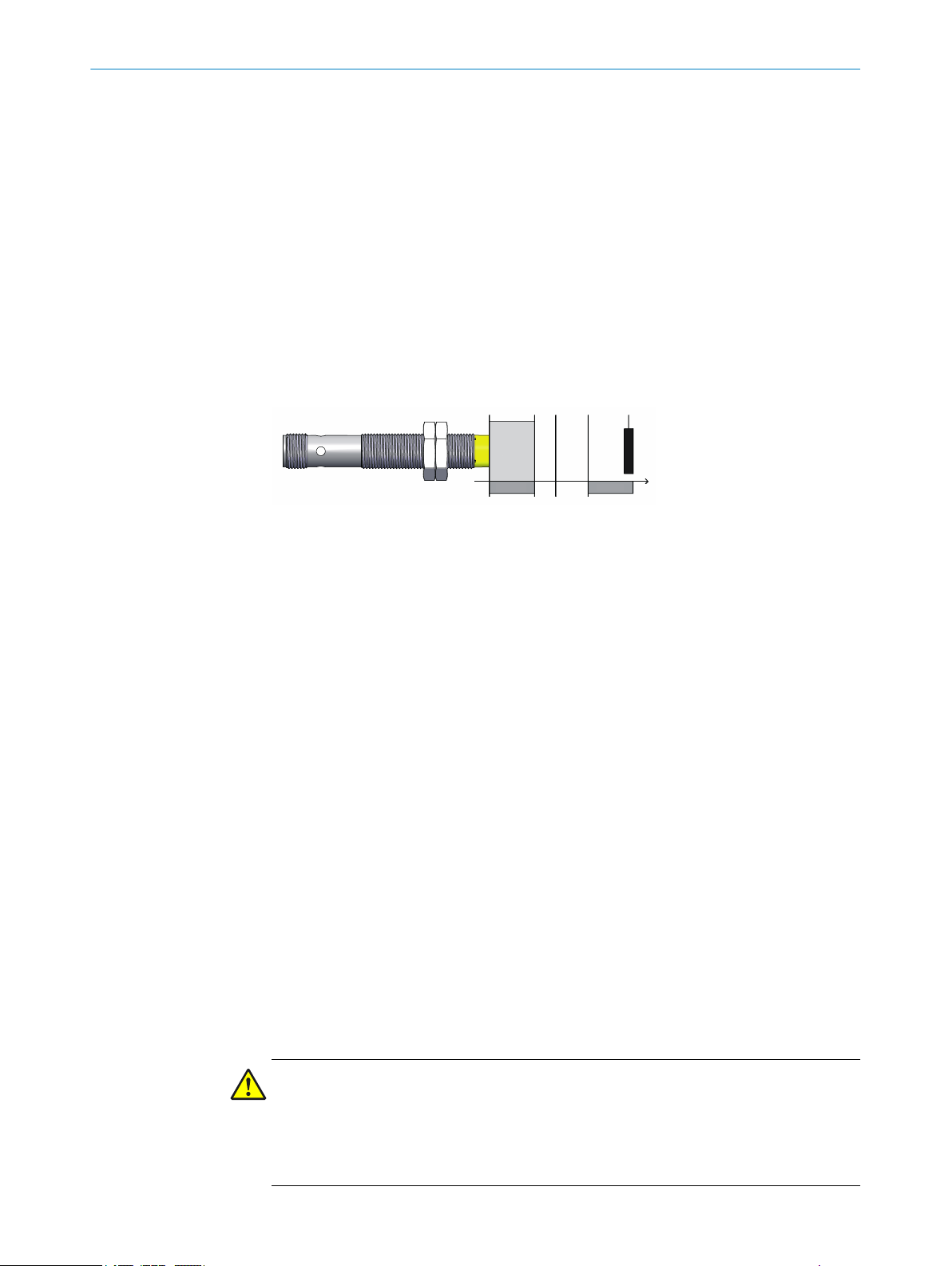
3.1 Structure and function
Description of operation
he safety switch is an inductive safety switch which is activated by actuating elements
T
(metal objects) without making contact.
If an actuating element is situated between the active sensor surface and assured
switch-off distance Sao, safety outputs (OSSDs) are safe in the ON state. If an actuating
element is situated outside assured safe switch-off distance Sar, safety outputs
(OSSDs) are in the OFF state.
The machine or its control must safely analyze the signals (for example using a safe
control or safety relays) and stop the dangerous state.
PRODUCT DESCRIPTION 3
Safety switches
1
Assured switch-on distance S
2
Sensing range Sn (switch-on distance under laboratory conditions)
3
Assured switch off distance S
4
Actuating element
5
ao
ar
Assured switch on distance (Sao)
tance from the active sensor surface within which the presence of the actuating ele‐
Dis
ment can be safely detected.
The assured switch-on distance is the important value for safe applications.
Sensing range (Sn)
Is de
tected under laboratory conditions.
Typical sensing range of the safety switch. The sensing range can change with the
shape and material of the actuating element. Manufacturing tolerances as well as
external influences such as temperature or supply voltage are not considered.
Assured switch off distance (Sar)
Dis
tance from the active sensor surface outside of which the presence of the actuating
element is reliably detected.
3.2 Product characteristics
3.2.1 Protective functions
DANGER
L
oss of cross-circuit monitoring when output load at the OSSDs is too high
Loss of safety function
The safety switch must always be operated within the limits of the prescribed and
b
8023341/14TD/2019-08-08 | SICK OP E RA T IN G I N ST R UC T IO N S | IME2S
Subject to change without notice
specified technical data.
9
Page 10
1
RODUCT DESCRIPTION
3 P
The safety switch is available for the following internal protective functions:
•
•
•
•
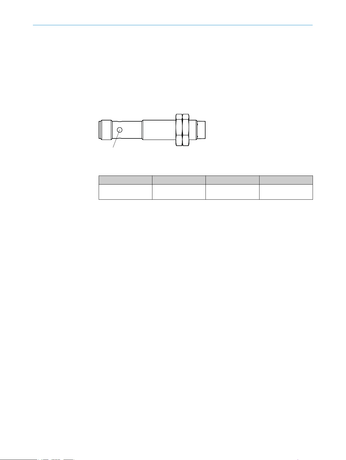
3.2.2 Status indicators
LEDs on the device
T
he safety switch signals the operational status via an LED.
Figure 1: LED IME2S
Table 2: LED
Item Name Color Purpose
1
hort-circuit protection at all outputs
S
Cross-circuit monitoring at the OSSDs
Overload protection at the OSSDs
Supply voltage reverse polarity protection
STATE Green/Red Signals when an
ject is detected.
ob
Further topics
see "F
•
ault indicators", page 22
10
O PE R AT I NG IN S TR U CT I ON S | IME2S 8023341/14TD/2019-08-08 | SICK
Subject to change without notice
Page 11
4 Project planning
4.1 Manufacturer of the machine
DANGER
F
ailure to comply with manufacturer’s obligations
Hazard due to lack of effectiveness of the protective device
Carry out a risk assessment before using the safety switch.
b
Do not tamper with, open, or modify the components of the safety switch.
b
Do not repair defective devices – they must be replaced instead.
b
Make sure that switch-on commands which bring about a dangerous state of the
b
machine are not enabled until the protective device is closed.
Ensure that a stop command is triggered if the actuating element is no longer
b
detected (e.g. when the protective device is opened during a hazardous machine
status).
The safety switches must not be circumvented (contacts bypassed), rotated away,
b
removed, or rendered ineffective in any other way. Put measures in place to
reduce possibilities for circumvention.
PROJECT PLANNING 4
4.2 Operating entity of the machine
DANGER
F
ailure to observe operator obligations
Hazard due to lack of effectiveness of the protective device
Changes to the machine and changes to the mechanical mounting of the safety
b
switch necessitate a new risk assessment. The results of this risk assessment
may require the entity operating the machine to meet the obligations of a manu‐
facturer.
Apart from the procedures described in this document, the components of the
b
safety switch must not be opened or modified.
Do not carry out any repair work on components. Improper repair of the safety
b
switch can lead to a loss of the protective function.
4.3 Design
Important information
DANGER
B
ypassing the protective device
Hazard due to lack of effectiveness of the protective device
Avoid incentives to manipulate the safety switch by taking at least one of the fol‐
b
lowing measures:
Attach safety switch outside of the sensing range.
°
Cover safety switch with obstacles or shield.
°
Attach safety switch at the covered position.
°
If possible, do not mount the safety switch with the active sensor surface fac‐
°
ing upwards.
8023341/14TD/2019-08-08 | SICK OP E RA T IN G I N ST R UC T IO N S | IME2S
Subject to change without notice
11
Page 12

4 P
ROJECT PLANNING
DANGER
amage to the safety switch due to mechanical stress
D
Loss of safety function
Protect the safety switch from mechanical stress such as impacts or permanent
b
contact pressure, for example with an additional stop
Mounting location
Se
lect the mounting location so that the safety switch is protected from impacts and
mechanical pressure. If necessary, attached additional stop.
Measures to protect against unintentional actuation
The safety switch can be actuated by any metal objects such as metal chips, doors or
moving machine elements. Constructive measures must be taken so that the safety
switch is only actuated by the intended actuating element.
Distance
If several safety switches are mounted on the machine, they must be mounted at a min‐
imum distance to one another.
Alignment
The safety switch can be mounted with any alignment. If the safety sensor is mounted
with the sensor surface facing upwards, the risk of unintended actuation by loose metal
objects (for example metal chips) or manipulation of the safety switch increases.
Possible mounting methods
There are several mounting methods. The permitted mounting method depends on the
product variant:
Flush mounting. The active sensor surface is at the same level as the surrounding
•
material.
Non-flush mounting. The active sensor surface protrudes a bit out of the surround‐
•
ing material.
Further topics
lush mounting", page 15
see "F
•
see "Non-flush mounting", page 16
•
4.3.1 Determining the sensing ranges
Sensing ranges Sao, Sar and Sn depend on t
ment. The specified values assume the following prerequisites:
Length and width of the actuating element: Diameter of the active sensor surface
•
Material thickness: 1 mm
•
Material of the actuating element: Structural steel (FE360)
•
Ambient temperature: 25 °C
•
If the actuating element consists of another material, the specified values for Sao, S
and Sn must be multiplied with the respective correction factor (see table 3, page 13)
(values of sensing ranges see table 11, page 25).
he material and form of the actuating ele‐
ar
12
O PE R AT I NG IN S TR U CT I ON S | IME2S 8023341/14TD/2019-08-08 | SICK
Subject to change without notice
Page 13

OSSD 1
V
t
1
2
V
t
2
OSSD 2
2 2
PROJECT PLANNING 4
Table 3: Correction factor for sensing ranges Sao, Sar and S
Material Correction factor
Mu-metal 1.2
Molded metal 1.1
Structural steel (Fe 360) 1.0
Rust-free steel (V2A, 304) 0.8
Aluminum 0.45
Copper 0.3
Brass 0.4
Example calculation
F
or a copper actuating element, the safe switch-off distance changes as follows:
S
ao/copper
= Sao * 0.3
4.4 Integration in the electrical control
Switch-on commands that put the machine in a dangerous state may only be activated
he safety switch detects an actuating element. When the machine goes into a
when t
dangerous state, a stop command must be triggered if no suitable object is detected.
Depending on the safety concept, the signal is analyzed by safety relays or a safety con‐
troller, for example.
n
The connected control and all devices responsible for safety must comply with the
required performance level and the required category (for example, according to
EN ISO 13849-1:2015).
4.4.1 Course of the OSSD test over time
The safety locking device tests the OSSDs for self-diagnosis at regular intervals. To
do t
his, the safety locking device switches each OSSD briefly to the OFF state and
checks whether this channel is voltage-free during this time.
Make sure that the machine’s control does not react to these test pulses and the
machine does not switch off.
Figure 2: Course of the OSSD test over time
Legend number Description Value
1
2
Test pulse interval Usually every 20 ms
Test pulse width 300 μs
8023341/14TD/2019-08-08 | SICK OP E RA T IN G I N ST R UC T IO N S | IME2S
Subject to change without notice
13
Page 14

ROJECT PLANNING
4 P
4.5 Thorough check concept
The safety switch must be tested by appropriately qualified safety personnel during
ommissioning, after modifications, and at regular intervals; see "Requirements for the
c
thorough check during commissioning and in certain situations", page 14.
Regular thorough checks serve to investigate the effectiveness of the safety switch and
discover defects resulting from modifications or external influences (such as damage or
manipulation).
The manufacturer and operating entity must define the type and frequency of the thor‐
ough checks on the machine on the basis of the application conditions and the risk
assessment. The process of defining the thorough checks must be documented in a
traceable manner.
4.5.1 Requirements for the thorough check during commissioning and in certain situations
The protective device and its application must be thoroughly checked in the following
sit
uations:
Before commissioning
•
After changes to the configuration or the safety function
•
After changes to the mounting, the alignment, or the electrical connection
•
After exceptional events, such as after a manipulation has been detected, after
•
modification of the machine, or after replacing components
The thorough check ensures the following:
All relevant regulations are complied with and the protective device is active for all
•
of the machine’s operating modes.
The documentation corresponds to the state of the machine, including the protec‐
•
tive device
The thorough checks must be carried out by qualified safety personnel or specially qual‐
ified and authorized personnel and must be documented in a traceable manner.
k whether the protective device of the machine is effective in all operating
Chec
b
modes in which the machine can be set.
Make sure that operating personnel have been instructed in the function of the
b
protective device before starting work on the machine. The machine operator has
overall responsibility for the instruction, which must be carried out by qualified per‐
sonnel.
4.5.2 Minimum requirements for regular thorough checks
The following thorough checks must be carried out at least once a year:
horough check of the principal protective function of the safety switch
T
•
Thorough check of assured sensing range S
•
Thorough check for damage on the switch housing
•
Thorough check for damage on the switch cables
•
Thorough check for signs of misuse or manipulation on the safety switch
•
ar
14
O PE R AT I NG IN S TR U CT I ON S | IME2S 8023341/14TD/2019-08-08 | SICK
Subject to change without notice
Page 15

5 Mounting
2
1
3
6
5.1 Flush mounting
Important information
DANGER
If t
he safety switch is not mounted with the intended mounting method, the switching
behavior is affected. The safety switch might not switch as intended.
b
b
b
Approach
b
MOUNTING 5
Only use safety switches for flush mounting which are intended for flush mounting.
Only use safety switches for non-flush mounting which are intended for non-flush
mounting.
If something is unclear, use the part number to check for which mounting method
the safety switch is suited (see "Ordering information", page 32).
serve the max. tightening torque during mounting.
Ob
IME2S: 12 Nm
°
Figure 3: Distances for flush mounting
8023341/14TD/2019-08-08 | SICK OP E RA T IN G I N ST R UC T IO N S | IME2S
Subject to change without notice
Figure 4: Distance with 2 opposing safety
switches
15
Page 16

2
1
3
4
4
5
5 MOUNTING
Table 4: Dimensions for flush mounting in mm
Variant
IME2S12-04***** 12 > 24 > 12 > 32
IME2S18-05***** 18 > 36 > 15 > 40
IME2S18-08***** 18 > 36 > 24 > 64
IME2S30-12***** 30 > 60 > 36 > 96
General formula –
5.2 Non-flush mounting
1
Diame
ter of the safety switch
2
Minimum dis‐
tance to the
neighboring
safety switch
2 × 1
3
Minimum free
space above the
active sensor
surface
> 3 × S
n
6
Minimum dis‐
tance to the
opposing safety
switch
> 8 × S
Important information
DANGER
If t
he safety switch is not mounted with the intended mounting method, the switching
behavior is affected. The safety switch might not switch as intended.
n
Only use safety switches for flush mounting which are intended for flush mounting.
b
Only use safety switches for non-flush mounting which are intended for non-flush
b
mounting.
If something is unclear, use the part number to check for which mounting method
b
the safety switch is suited (see "Ordering information", page 32).
Approach
or mounting, observe max. tightening torque: 12 Nm
F
b
16
Figure 5: Distances for non-flush mounting
O PE R AT I NG IN S TR U CT I ON S | IME2S 8023341/14TD/2019-08-08 | SICK
Subject to change without notice
Page 17

6
MOUNTING 5
Figure 6: Distance for 2 opposing safety
switches
Table 5: Dimensions for non-flush mounting in mm
Variant
General formula –
IME2S12-04***** 12 > 24 > 12 > 12 > 8 > 32
IME2S12-08***** 12 > 24 > 24 > 12 > 16 > 64
IME2S18-08***** 18 > 36 > 24 > 18 > 16 > 64
IME2S30-15***** 30 > 60 > 45 > 30 > 30 > 120
1
Diame
ter of
the safety
switch
2
Minimum
distance to
the neighbor‐
ing safety
switch
> 2 × 1
3
Minimum free
space above the
active sensor
surface
> 3 × S
n
4
Minimum
free space
around the
active sensor
surface
> 1 × 1
5
Overrun of
the active
sensor sur‐
face
> 2 × S
n
6
Minimum
distance to
the opposing
safety switch
> 8 × S
n
8023341/14TD/2019-08-08 | SICK OP E RA T IN G I N ST R UC T IO N S | IME2S
Subject to change without notice
17
Page 18

6 ELE
CTRICAL INSTALLATION
6 Electrical installation
6.1 Safety
Important information
DANGER
H
azard due to electrical voltage
Hazard due to unexpected starting of the machine
Make sure that the machine is and remains disconnected from the power supply
b
during the electrical installation.
Make sure that the dangerous state of the machine is and remains switched off
b
during electrical installation.
Make sure that the outputs of the safety switch have no effect on the machine
b
during electrical installation.
DANGER
Hazard due to lack of effectiveness of the protective device
The dangerous state may not be stopped in the event of non-compliance.
Always connect the two OSSDs separately. The two OSSDs must not be connected
b
to each other.
Connect the OSSDs such that the machine controller processes both signals sepa‐
b
rately.
Isolated connection of OSSD1 and OSSD2
Figure 7: Dual-channel and isolated connection of OSSD1 and OSSD2
Avoiding any potential difference between load and protective device
18
ou connect loads to the output signal switching devices (switching outputs) that then
If y
also switch if controlled with negative voltage (e.g., electro-mechanical contactor with‐
out reverse polarity protection diode), you must connect the 0 V connections of these
loads and those of the corresponding protective device separately and also directly to
the same 0 V terminal strip. In the event of a fault, this is the only way to ensure that
there can be no potential difference between the 0 V connections of the loads and
those of the corresponding protective device.
O PE R AT I NG IN S TR U CT I ON S | IME2S 8023341/14TD/2019-08-08 | SICK
Subject to change without notice
Page 19

Figure 8: No potential difference between load and protective device
12
3 4
6.2 Notes on cULus
Important information
DANGER
k of burns from hot housing
Ris
ELECTRICAL INSTALLATION 6
Take measures to make sure the safety switch cannot be touched during opera‐
b
tion.
For use according to the requirements of UL 60947-5-2, the following conditions must
also be me
•
•
t:
The voltage supply must correspond to Class 2 in accordance with UL 508
Voltage supply Uv secured with 1 A fuse
6.3 System connection (M12, 4-pin)
Figure 9: System connection pin assignment (male connector)
Table 6: Device connection pin assignment (male connector, M12, 4-pin, A-coded)
Pin Wire color
1 Brown +24 V DC Voltage supply 24 V DC
2 White OSSD 1 Output OSSD1
3 Blue 0 V Voltage supply 0 V DC
4 Black OSSD 2 Output OSSD2
1)
Applies to the extension cables recommended as accessories.
1)
Designation Description
P
ay attention to seal tightness of the plug connector.
b
8023341/14TD/2019-08-08 | SICK OP E RA T IN G I N ST R UC T IO N S | IME2S
Subject to change without notice
19
Page 20

6 ELECTRICAL INSTALLATION
6.4 System connection (open cable end, 4-pin)
Table 7: Device connection pin assignment (open cable end, 4-pin)
Wire color Designation Description
Brown +24 V DC Voltage supply 24 V DC
White OSSD 1 Output OSSD1
Blue 0 V Voltage supply 0 V DC
Black OSSD 2 Output OSSD2
20
O PE R AT I NG IN S TR U CT I ON S | IME2S 8023341/14TD/2019-08-08 | SICK
Subject to change without notice
Page 21

7 Commissioning
7.1 Safety
DANGER
H
azard due to lack of effectiveness of the protective device
In the case of non-compliance, it is possible that the dangerous state of the machine
may not be stopped or not stopped in a timely manner.
1. Before commissioning the machine, have it checked and released by qualified
safety personnel.
2. Make sure that the time for the safety requirement (closing the protective device
again) is longer than the response time.
7.2 Switching on
Approach
1. Verify that the actuating element is not located within the assured switch-off dis‐
tance.
2. Switch on the supply voltage.
COMMISSIONING 7
7.3 Adjustment
As soon as the supply voltage is applied, the safety switch initializes automatically.
When the STATE LED permanently lights up red, the safety switch is ready for operation.
Table 8: LED displays and OSSD status during commissioning
STATE LED OSSDs Device state
Ö Gr
O R
ed
OGr
een/Red
een
OFF state Safety switch initializes.
OFF state The safety switch is switched
ctuating object is not
on. A
detected.
ON state The safety switch is switched
ctuating object is
on. A
detected.
Further topics
ault indicators", page 22
see "F
•
Adjusting distance
A
djust the distance between the safety switch and actuating element so that the
b
actuating object is reliably detected within assured switch-off distance Sao (LED
STATE permanently green).
Complementary information
NOTE
F
or variants with cylindrical housing, the distance can be adjusted by rotating the safety
switch in or out.
8023341/14TD/2019-08-08 | SICK OP E RA T IN G I N ST R UC T IO N S | IME2S
Subject to change without notice
21
Page 22

8 TROUBLESHOOTING
8 Troubleshooting
8.1 Safety
DANGER
H
azard due to lack of effectiveness of the protective device
In the case of non-compliance, it is possible that the dangerous state of the machine
may not be stopped or not stopped in a timely manner.
Immediately shut the machine down if the behavior of the machine cannot be
b
clearly identified.
If a machine fault cannot be definitively determined or safely rectified, immediately
b
shut the machine down.
Secure the machine so that it cannot switch on unintentionally.
b
NOTE
A
dditional information on troubleshooting can be found at the responsible SICK sub‐
sidiary.
8.2 Fault indicators
Table 9: Fault indicators
LED STATE Possible cause Corrective measure
Green Red
o o
o Ö (4 Hz)
o Ö (1 Hz)
No supply voltage
Internal error
Supply voltage too high or
t
oo low
External error
witch on the supply voltage.
S
•
Switch the voltage supply off and
•
on.
If the error occurs again, the sen‐
•
sor is defective. Replace sensor.
k the supply voltage.
Chec
•
k wiring for cross-circuit and
Chec
•
short-circuit.
Switch the voltage supply off and
•
on.
If the error occurs again, the sen‐
•
sor is defective. Replace sensor.
22
O PE R AT I NG IN S TR U CT I ON S | IME2S 8023341/14TD/2019-08-08 | SICK
Subject to change without notice
Page 23

9 Maintenance
9.1 Cleaning
NOTICE
b
b
b
MAINTENANCE 9
D
o not use aggressive cleaning agents (such as isopropanol or spirit).
Do not use any substances that hinder the wetting properties of lacquers.
We recommend anti-static cleaning agents.
8023341/14TD/2019-08-08 | SICK OP E RA T IN G I N ST R UC T IO N S | IME2S
Subject to change without notice
23
Page 24

10 DECOMMISSIONING
10 Decommissioning
10.1 Disposal
Approach
ways dispose of unusable devices in accordance with national waste disposal
Al
b
regulations.
Complementary information
SICK will be glad to help you dispose of these devices on request.
24
O PE R AT I NG IN S TR U CT I ON S | IME2S 8023341/14TD/2019-08-08 | SICK
Subject to change without notice
Page 25

11 Technical data
11.1 Data sheet
Table 10: Safety-related parameters
Safety-related parameters
Performance level PL d (EN ISO 13849-1:2015)
Category Category 2 (EN ISO 13849-1:2015)
Safety integrity level SIL 2 (IEC 61508)
SIL claim limit SILCL 2 (IEC 62061)
PFHd (mean probability of a dangerous failure per hour)
For operating heights ≤ 1,000 m above sea
vel
le
For operating heights 1,001 m … 2,000 m
above sea level
For operating heights 2,001... 3,000 m
above sea level
TM (mis
Type Type 3 (ISO 14119)
Safe status when a fault occurs At least one safety-related semiconductor out‐
TECHNICAL DATA 11
6 × 10⁻⁸ at 40 °C
7 × 10⁻⁸ at 40 °C
8 × 10⁻⁸ at 40 °C
sion time) 20 years (EN ISO 13849–1:2015)
SSD) is in the OFF state.
put (O
Table 11: Features
Features
Assured switch-on distance Sao
1)
IME2S**-04***** 3.2 mm
IME2S**-08***** 6.5 mm
IME2S**-05***** 4 mm
IME2S**-12***** 9.6 mm
IME2S**-15***** 12 mm
Assured switch off distance Sar
1)
IME2S**-04***** 6 mm
IME2S**-08***** 12 mm
IME2S**-05***** 7.5 mm
IME2S**-12***** 18 mm
IME2S**-15***** 22.5 mm
Sensing range Sn
1)
IME2S**-04***** 4 mm
IME2S**-08***** 8 mm
IME2S**-05***** 5 mm
IME2S**-12***** 12 mm
IME2S**-15***** 15 mm
Actuating frequency ≤ 100 Hz
1)
Specified values apply to steel (FE360). A correction factor must be used for other materials see
table 3.
8023341/14TD/2019-08-08 | SICK OP E RA T IN G I N ST R UC T IO N S | IME2S
Subject to change without notice
25
Page 26

11 TECHNICAL DATA
Table 12: Correction factor for sensing ranges Sao, Sar and S
n
Material Correction factor
Mu-metal 1.2
Molded metal 1.1
Structural steel (Fe 360) 1.0
Rust-free steel (V2A, 304) 0.8
Aluminum 0.45
Copper 0.3
Brass 0.4
Table 13: Interfaces
Interfaces
System connection (voltage supply and local inputs and outputs)
IME2S12 Cable with M12 male connector, 4-pin
M12 male connec
tor, 4-pin
Open cable
IME2S18 M12 male connector, 4-pin
IME2S30 M12 male connector, 4-pin
Table 14: Electrical data
Electrical data
Protection class III (EN 61140/IEC 61140)
Supply voltage V
S
Residual ripple ±10%
Rated insulation voltage U
i
Voltage drop (of supply voltage) ≤ 3 V
DC 24 V (19.2 V DC … 28.8 V DC)
1)
28.8 V
2)
Contamination degree 3 (external, according to EN 60947-1)
Rated impulse withstand voltage U
p
im
1,500 V
Utilization category (IEC 60947-5-1) DC-12: 24 V / 20 mA
Device fuse 1 A
Current consumption at 24 V < 20 mA
Hysteresis ≤ 15% of S
n
Repeatability 2%
Power-up delay (after supply voltage applied) 3)< 1 s
Response time (removal from response range) < 1 ms
Release time (response time when approaching response range)
IME2S12 < 1 ms
IME2S18-05B4DC0 < 2 ms
IME2S18-05B4DC0 < 1 ms
IME2S18-08N4DC0 < 1.5 ms
IME2S30-15B4DC0 < 5 ms
IME2S30-15N4DC0 < 1 ms
26
O PE R AT I NG IN S TR U CT I ON S | IME2S 8023341/14TD/2019-08-08 | SICK
Subject to change without notice
Page 27

TECHNICAL DATA 11
Electrical data
Risk time
1)
2)
3)
4)
Table 15: Mechanical data
Dimensions see "Dimensional drawings", page 28
Material IME2S
Tightening torque for mounting
Weight see "Table of weights", page 28
4)
Within the limits of UV.
AT 50 mA at each OSSD channel
Once the supply voltage has been switched on, the OSSDs are in the OFF state during the time delay
be
fore availability.
The risk time is the time needed to detect internal and external faults. External errors affect the OSSDs
(short-circuit to an OSSD and cross-circuit between the two OSSDs). At least one of the two OSSDs is
safely switched off during the risk time.
< 20 ms
Housing Nickel plated brass
Sensor surface Vistal
®
Cable PVC
Fixing nuts Brass alloy
IME2S 12 Nm
Table 16: Outputs
Outputs
Switching outputs 2 PNP semiconductors
Switching voltage
ON state 19.2 V DC … 28.8 V DC
OFF state 0 V DC … 2 V DC
Switching current
ON state ≤ 50 mA
OFF state < 500 µA
Load capacity 80 nF
Short-circuit protection Yes
Reverse polarity protection Yes
Test pulse width 300 µs
Table 17: Ambient data
Ambient data
Enclosure rating IP 67 (IEC 60529)
1)
Ambient operating temperature –25 °C … +70 °C
Temperature change rate ≤ 1 °K/min
Storage temperature –25 °C … +70 °C
Area of application (IEC 60654-1) Class C; weather-protected area of application
Operating altitude ≤ 3,000 m above sea level
Relative humidity 50% at 70 °C (IEC 60947-5-2)
Vibration resistance 1 mm / 10 Hz … 55 Hz (IEC 60947-5-2)
Shock resistance In accordance with IEC 60947-5-2
8023341/14TD/2019-08-08 | SICK OP E RA T IN G I N ST R UC T IO N S | IME2S
Subject to change without notice
27
Page 28

M12 x 1
63
52,3
40,9
LED 2 x 180°
17
4
2000
4
M12 x 1
17
LED 2 x 180°
63
52,3
36,9
2000
5
11 T
ECHNICAL DATA
Ambient data
EMC In accordance with IEC 60947-5-2, IEC
Minimum distance between 2 safety switches see "Mounting", page 15
1)
The adhesive strip above the LED displays must not be removed in order to achieve the specified enclo‐
sur
11.2 Table of weights
Table 18: Weight IME2S
Type code Weight in g
IME2S12-04B4DQ9 33
IME2S12-04N4DQ9 33
IME2S12-04B4DC0 18
IME2S12-04B4DW2 60
IME2S12-04N4DC0 18
IME2S12-04N4DW2 60
IME2S12-08N4DC0 18
IME2S18-05B4DC0 42
IME2S18-08N4DC0 38
IME2S18-08B4DC0 42
IME2S30-12B4DC0 102
IME2S30-15N4DC0 94
e rating.
60947-5-3 and IE
C 61000-6-7
11.3 Dimensional drawings
IME2S12
Figure 10: IME2S12-**B**W2 dimensional drawing
28
Figure 11: IME2S12-**N**W2 dimensional drawing
O PE R AT I NG IN S TR U CT I ON S | IME2S 8023341/14TD/2019-08-08 | SICK
Subject to change without notice
Page 29

M12 x 1
M12 x 1
65
52,3
40,9
LED 2 x 180°
17
4
Figure 12: IME2S12-**B**C0 dimensional drawing
M12 x 1
M12 x 1
65
52,3
36,9
LED 2 x 180°
17
4
5
M12 x 1
63
52,3
40,9
300
LED 2 x 180°
17
4
M12 x 1
63
52,3
36,9
300
LED 2 x 180°
17
5
4
TECHNICAL DATA 11
Figure 13: IME2S12-**N**C0 dimensional drawing
Figure 14: IME2S12-**B**Q9 dimensional drawing
Figure 15: IME2S12-**N**Q9 dimensional drawing
8023341/14TD/2019-08-08 | SICK OP E RA T IN G I N ST R UC T IO N S | IME2S
Subject to change without notice
29
Page 30

M18 x 1
M12 x 1
69
56,3
44,2
6,5
LED 2 x 180°
24
4
M18 x 1
M12 x 1
69
56,3
35,2 10
6,5
LED 2 x 180°
24
4
M30 x 1,5
M12 x 1
71
58,3
45,9
6,2
LED 2 x 180°
36
4
11 TECHNICAL DATA
IME2S18
Figure 16: IME2S18-**B**C0 dimensional drawing
Figure 17: IME2S18-**N**C0 dimensional drawing
IME2S30
Figure 18: IME2S30-**B**C0 dimensional drawing
30
O PE R AT I NG IN S TR U CT I ON S | IME2S 8023341/14TD/2019-08-08 | SICK
Subject to change without notice
Page 31

M30 x 1,5
M12 x 1
71
58,3
34,6
6,2
LED 2 x 180°
36
4
12,3
Figure 19: IME2S30-**N**C0 dimensional drawing
TECHNICAL DATA 11
8023341/14TD/2019-08-08 | SICK OP E RA T IN G I N ST R UC T IO N S | IME2S
Subject to change without notice
31
Page 32

12 ORDERING INFORMATION
12 Ordering information
12.1 Scope of delivery
Scope of delivery, IME2S
1 × IME2S s
•
2 × fixing nuts
•
1 × safety notes
•
Operating instructions for download: www.sick.com
•
afety switch
12.2 Ordering information
Table 19: IME2S ordering information
Design Housing diame‐
t
er
Cylindrical M12 Cable with M12
M18 M12 male con‐
M30 M12 male con‐
Sensor connec‐
tion type
male connec
4-pin
Cable with M12
male connector,
4-pin
M12 male con‐
nector, 4-pin
Open cable Flush IME2S12-04B4DW2 1091945
M12 male con‐
tor, 4-pin
nec
Open cable Non-flush IME2S12-04N4DW2 1091947
M12 male con‐
nector, 4-pin
tor, 4-pin
nec
M12 male con‐
nector, 4-pin
M12 male con‐
tor, 4-pin
nec
nector, 4-pin
M12 male con‐
tor, 4-pin
nec
Structural state Type code Part number
Flush IME2S12-04B4DQ9 1091142
tor,
Non-flush IME2S12-04N4DQ9 1091943
Flush IME2S12-04B4DC0 1091944
Non-flush IME2S12-04N4DC0 1091946
Non-flush IME2S12-08N4DC0 1091948
Flush IME2S18-05B4DC0 1091949
Non-flush IME2S18-08N4DC0 1091950
Flush IME2S18-08B4DC0 1091951
Flush IME2S30-12B4DC0 1091952
Non-flush IME2S30-15N4DC0 1091953
32
O PE R AT I NG IN S TR U CT I ON S | IME2S 8023341/14TD/2019-08-08 | SICK
Subject to change without notice
Page 33

13 Annex
13.1 Compliance with EU directives
EU declaration of conformity (extract)
he undersigned, representing the manufacturer, herewith declares that the product is
T
in conformity with the provisions of the following EU directive(s) (including all applicable
amendments), and that the standards and/or technical specifications stated in the EU
declaration of conformity have been used as a basis for this.
Complete EU declaration of conformity for download
You can call up the EU declaration of conformity and the current operating instructions
for the protective device by entering the part number in the search field at
www.sick.com (part number: see the type label entry in the “Ident. no.” field).
ANNEX 13
8023341/14TD/2019-08-08 | SICK OP E RA T IN G I N ST R UC T IO N S | IME2S
Subject to change without notice
33
Page 34

13 ANNEX
34
O PE R AT I NG IN S TR U CT I ON S | IME2S 8023341/14TD/2019-08-08 | SICK
Subject to change without notice
Page 35

ANNEX 13
8023341/14TD/2019-08-08 | SICK OP E RA T IN G I N ST R UC T IO N S | IME2S
Subject to change without notice
35
Page 36

Detailed addresses and further locations at www.sick.com
Australia
Phone +61 (3) 9457 0600
1800 33 48 02 – tollfree
E-Mail sales@sick.com.au
Austria
Phone +43 (0) 2236 62288-0
E-Mail office@sick.at
Belgium/Luxembourg
Phone +32 (0) 2 466 55 66
E-Mail info@sick.be
Brazil
Phone +55 11 3215-4900
E-Mail comercial@sick.com.br
Canada
Phone +1 905.771.1444
E-Mail cs.canada@sick.com
Czech Republic
Phone +420 234 719 500
E-Mail sick@sick.cz
Chile
Phone +56 (2) 2274 7430
E-Mail chile@sick.com
China
Phone +86 20 2882 3600
E-Mail info.china@sick.net.cn
Denmark
Phone +45 45 82 64 00
E-Mail sick@sick.dk
Finland
Phone +358-9-25 15 800
E-Mail sick@sick.fi
France
Phone +33 1 64 62 35 00
E-Mail info@sick.fr
Germany
Phone +49 (0) 2 11 53 010
E-Mail info@sick.de
Greece
Phone +30 210 6825100
E-Mail office@sick.com.gr
Hong Kong
Phone +852 2153 6300
E-Mail ghk@sick.com.hk
Hungary
Phone +36 1 371 2680
E-Mail ertekesites@sick.hu
India
Phone +91-22-6119 8900
E-Mail info@sick-india.com
Israel
Phone +972 97110 11
E-Mail info@sick-sensors.com
Italy
Phone +39 02 27 43 41
E-Mail info@sick.it
Japan
Phone +81 3 5309 2112
E-Mail support@sick.jp
Malaysia
Phone +603-8080 7425
E-Mail enquiry.my@sick.com
Mexico
Phone +52 (472) 748 9451
E-Mail mexico@sick.com
Netherlands
Phone +31 (0) 30 229 25 44
E-Mail info@sick.nl
New Zealand
Phone +64 9 415 0459
0800 222 278 – tollfree
E-Mail sales@sick.co.nz
Norway
Phone +47 67 81 50 00
E-Mail sick@sick.no
Poland
Phone +48 22 539 41 00
E-Mail info@sick.pl
Romania
Phone +40 356-17 11 20
E-Mail office@sick.ro
Russia
Phone +7 495 283 09 90
E-Mail info@sick.ru
Singapore
Phone +65 6744 3732
E-Mail sales.gsg@sick.com
Slovakia
Phone +421 482 901 201
E-Mail mail@sick-sk.sk
Slovenia
Phone +386 591 78849
E-Mail office@sick.si
South Africa
Phone +27 10 060 0550
E-Mail info@sickautomation.co.za
South Korea
Phone +82 2 786 6321/4
E-Mail infokorea@sick.com
Spain
Phone +34 93 480 31 00
E-Mail info@sick.es
Sweden
Phone +46 10 110 10 00
E-Mail info@sick.se
Switzerland
Phone +41 41 619 29 39
E-Mail contact@sick.ch
Taiwan
Phone +886-2-2375-6288
E-Mail sales@sick.com.tw
Thailand
Phone +66 2 645 0009
E-Mail marcom.th@sick.com
Turkey
Phone +90 (216) 528 50 00
E-Mail info@sick.com.tr
United Arab Emirates
Phone +971 (0) 4 88 65 878
E-Mail contact@sick.ae
United Kingdom
Phone +44 (0)17278 31121
E-Mail info@sick.co.uk
USA
Phone +1 800.325.7425
E-Mail info@sick.com
Vietnam
Phone +65 6744 3732
E-Mail sales.gsg@sick.com
8023341/14TD/2019-08-08/en
SICK AG | Waldkirch | Germany | www.sick.com
 Loading...