

Page 1

IDM Corded / Bluetooth
HAND-HELD SCANNERS
OPERATING INSTRUCTIONS
Page 2
General Remarks
Operating Instructions
& IDM Bluetooth
2
© SICK AG · Germany · All rights reserved · Subject to change without notice
8017159/142O/2019-05-23
EN61000-6-22
Class B ITE
IDM corded
General Remarks
Further information on the IDM Hand-held scanners can be found on the internet on the IDM product page at
www.sick.com
• Detailed technical data in the online data sheet
• Overview of accessories
• Configuration software IDM Set Up Tool
• EC Declaration of conformity
• Identification solutions product catalog
• Product information Hand-held scanners
Print out this manual
If you want to print out this manual please ensure that the original size is remained and the print out is of
good quality. Otherwise the configuration codes contained in this manual may be distorted and cannot be
scanned anymore.
Regulatory
EN61000-3-2/ EN61000-3-31,
EN60950-1, EN61000-6-3,
KN22, KN24 (KN61000-2,-3,-4,-5,-6,-8,-11)3
4
Clause 2, Article 58-2 of Radio Waves Act
Part 15B, Part 15C
CNS13438, CNS14336
AS/NZS CISPR 22:2009 Class B LED Eye Safety IEC62471 Exempt group
LP0002 Laser Eye Safety IEC60825-1 Class 1
4
V-3/2011.04, TECHNICAL REQUIREMENTS,
Copyright
Copyright © 2019
SICK AG Waldkirch
Germany
Trademark
Adobe™ Reader™ is a trademark of Adobe Systems Incorporated.
3
MIC T401
1
Relevant for IDM Corded Hand-held scanners with power supply.
2
At the presence of high frequency interference in the frequency range of 15 MHz to 50 MHz there may be performance restrictions.
3
Relevant for IDM Corded Hand-held scanners
4
Relevant for IDM Bluetooth Hand-held scanners
Page 3

Operating Instructions
Table of contents
IDM corded
8017159/142O/2019-05-23
© SICK AG · Germany · All rights reserved · Subject to change without notice
3
& IDM Bluetooth
Table of contents
1 Getting familiar with your IDM Hand-held scanner ........................................................................................ 6
1.1 Connectivity ....................................................................................................................................... 8
1.1.1 Standard Interfaces (RS-232, USB) .................................................................................... 8
1.1.2 Industrial fieldbus ................................................................................................................ 9
1.2 Technical Specifications ................................................................................................................. 10
1.2.1 IDM Corded Hand-held Scanners ..................................................................................... 10
1.2.2 IDM Bluetooth Hand-held Scanners ................................................................................. 11
2 IDM Bluetooth Scanners ................................................................................................................................... 12
2.1 Preparation before using ................................................................................................................ 12
2.1.1 Battery installation ............................................................................................................. 12
2.1.2 Charging the battery .......................................................................................................... 12
2.1.3 Placing the scanner into the cradle .................................................................................. 13
2.1.4 USB Bus power ................................................................................................................... 13
2.1.5 Indications .......................................................................................................................... 14
2.2 Paging Function .............................................................................................................................. 15
2.3 Radio Link Mode ............................................................................................................................. 15
2.3.1 PAIR Mode .......................................................................................................................... 16
2.3.2 PICO Mode .......................................................................................................................... 16
2.3.3 HID Mode ............................................................................................................................ 18
2.3.4 SSP Master/ Slave Mode .................................................................................................. 20
2.4 Out-of-Range Scanning
2.5 Presentation Scanning ................................................................................................................... 22
2.6 Battery status (IDM Bluetooth only) ............................................................................................... 22
2.7 Sleep Mode & Power Off ................................................................................................................ 22
2.8 Batch Scanning (Inventory Mode) .................................................................................................. 23
2.8.1 Quantity feature ................................................................................................................. 23
2.8.2 Data output format ............................................................................................................ 24
2.8.3 Transmit stored data ......................................................................................................... 25
2.8.4 Delete data ......................................................................................................................... 25
3 Configuration via Barcodes .............................................................................................................................. 26
3.1 Programming Commands ............................................................................................................... 26
3.1.1 System Command .............................................................................................................. 26
3.1.2 Family Code ........................................................................................................................ 26
3.1.3 Option Code ........................................................................................................................ 26
3.2 Programming Procedures ............................................................................................................... 26
3.2.1 Program & End ................................................................................................................... 27
3.2.2 System List & Master Default ........................................................................................... 28
3.2.3 Single Scan ......................................................................................................................... 28
3.2.4 Multiple Scan ..................................................................................................................... 29
3.2.5 Cycling Scan ....................................................................................................................... 30
3.2.6 Dual Level Scan ................................................................................................................. 31
3.3 Host Interface Selection
3.4 Keyboard Interface Control ............................................................................................................ 33
3.4.1 Keyboard Layout (Language) ............................................................................................ 33
3.4.2 Suffix, Preamble, Postamble, FNC1 Transmit, Caps Lock ............................................... 34
3.4.3 Delay Settings .................................................................................................................... 35
................................................................................................................... 21
................................................................................................................. 32
Page 4

Table of contents
Operating Instructions
& IDM Bluetooth
4
© SICK AG · Germany · All rights reserved · Subject to change without notice
8017159/142O/2019-05-23
IDM corded
3.4.4 Function Key, Key Pad Emulation, Upper/Lower Case, Dollar Sign .............................. 36
3.4.5 Barcode Encoding Format, Keyboard Output ................................................................... 36
3.5 Serial Interface Control ................................................................................................................... 39
3.5.1 Suffix, Preamble, Postamble ............................................................................................. 39
3.5.2 Delay Settings .................................................................................................................... 40
3.5.3 Handshaking Protocol, ACK/ NAK .................................................................................... 41
3.5.4 Response Time-out, Baud Rate ........................................................................................ 42
3.5.5 Data Frame ......................................................................................................................... 43
3.6 Wand/ Laser Emulation Control (IDM1xx series) .......................................................................... 44
3.6.1 Output Polarity, Signal State, Margin/ Module Time ....................................................... 44
3.7 Symbology Reading Control ............................................................................................................ 45
3.7.1 User Defined Symbol ID ..................................................................................................... 45
3.7.2 Symbology ID Transmission .............................................................................................. 46
3.7.3 Readable Bar Codes .......................................................................................................... 47
3.7.4 Code 39/ Code 32 ............................................................................................................. 49
3.7.5 Code 39 .............................................................................................................................. 50
3.7.6 Codabar/ NW-7 .................................................................................................................. 51
3.7.7 UPC-A/ UPC-E ..................................................................................................................... 52
3.7.8 EAN Code ............................................................................................................................ 55
3.7.9 UCC Coupon Extended Code ............................................................................................. 57
3.7.10 IATA & Interleaved 2 of 5 ................................................................................................ 58
3.7.11 Code 25 Family ................................................................................................
................ 59
3.7.12 Code 11 & Code 93 ......................................................................................................... 60
3.7.13 MSI/ Plessey .................................................................................................................... 61
3.7.14 Code 128 ......................................................................................................................... 62
3.7.15 GS1-128 ........................................................................................................................... 64
3.7.16 UK/ Plessey ...................................................................................................................... 66
3.7.17 Telepen ............................................................................................................................. 67
3.7.18 GS1 DataBar .................................................................................................................... 68
3.7.19 Composite Codes, Codablock F, PDF417, Micro PDF417 ............................................ 69
3.7.20 Code 16K & Code 49 ...................................................................................................... 70
3.7.21 QR Code ........................................................................................................................... 71
3.7.22 Data Matrix ....................................................................................................................... 72
3.7.23 Aztec Code ....................................................................................................................... 73
3.7.24 Autralian Post, US Planet, US Postnet, British Post, Japan Post, Posti 4-State ........... 74
3.7.25 Netherland KIX Code, Intelligent Mail, Korea Post Code ............................................. 75
3.7.26 MaxiCode Setting ............................................................................................................. 76
3.7.27 DPM Code ........................................................................................................................ 77
3.8 Operation Mode .............................................................................................................................. 78
3.8.1 Corded scanners (IDMxx0 series) ..................................................................................... 78
3.8.2 Bluetooth scanners (IDMxx1 series) ................................................................................. 79
3.9 Operation Control ............................................................................................................................ 80
3.9.1 Buzzer, Power On LED, Good read indicator, Vibrator Control ........................................ 80
3.9.2 Buzzer Volume
................................................................................................................... 81
3.9.3 Redundancy, 1D Code Inverse Reading ........................................................................... 82
3.9.4 Reread Delay, Good Read Delay Control .......................................................................... 83
3.9.5 Light Source On Time, Hands Free Time-out .................................................................... 84
3.9.6 Presentation Auto-Sense, Sensitivity ................................................................................ 86
3.9.7 Presentation Control, Scan Rate, Flash Duty ................................................................... 87
Page 5

Operating Instructions
Table of contents
IDM corded
8017159/142O/2019-05-23
© SICK AG · Germany · All rights reserved · Subject to change without notice
5
& IDM Bluetooth
3.9.8 Illumination Control, Presentation Background Lighting ................................................. 88
3.9.9 Aiming, Delay Aiming Time-out, Decode Aiming .............................................................. 89
3.9.10 Center Alignment, Unique Barcode Reporting ............................................................... 90
3.9.11 1D Barcode Reading Direction ....................................................................................... 91
3.9.12 Motion Control ................................................................................................................. 92
3.9.13 Timestamp Functions ...................................................................................................... 93
3.9.14 Scene mode ..................................................................................................................... 95
3.10 Bluetooth Operation Control (IDM Bluetooth series) .................................................................... 96
3.10.1 Out-of-range Scanning, Beeping Control ........................................................................ 96
3.10.2 Radio-off Time-Out, Sleep Time-out, Power Off Time-out .............................................. 97
3.10.3 Bluetooth Batch Scanning .............................................................................................. 98
3.10.4 Bluetooth Device name, Security Settings ................................................................... 100
3.10.5 HID Link Quality, Power Saving Mode .......................................................................... 101
3.11 Batch Reading (IDM2xx series) .................................................................................................... 102
3.12 Condensed Data Wizard ............................................................................................................... 105
3.12.1 Preamble, Postamble, Data Length, Symbol ID Transmission ................................... 105
3.12.2 Data Formatter .............................................................................................................. 106
3.12.3 Data Verifier ................................................................................................................... 107
3.12.4 Data Replacer ................................................................................................................ 108
3.12.5 Data Organizer ............................................................................................................... 109
3.12.6 Select Barcode Symbology ............................................................................................ 110
3.12.7 Position Calculation ....................................................................................................... 111
3.12.8 Application Example ...................................................................................................... 111
4 IDM Set Up Tool ...............................................................................................................................................113
4.1 Configuration via IDM Set Up Tool ............................................................................................... 113
4.1.1 IDM Corded Scanners ...................................................................................................... 113
4.1.2 IDM Bluetooth Scanners ................................................................................................. 113
4.2 Firmware Upgrade via IDM Set Up Tool ....................................................................................... 114
4.2.1 IDM Corded Scanner ........................................................................................................ 114
4.2.2 IDM Bluetooth Scanner ................................................................................................... 114
4.2.3 IDM Bluetooth Cradle ...................................................................................................... 115
5 Disposal .............................................................................................................................................................116
6 Appendix ...........................................................................................................................................................117
6.1 Symbology ID Table (1D Codes) ................................................................................................... 117
6.2 Symbology ID table (2D and Post codes) .................................................................................... 118
6.3 Keyboard Function Code Table .................................................................................................... 118
6.4 ASCII Input Shortcut (Reference Table) ....................................................................................... 119
6.5 GS1-128 ASCII Table .................................................................................................................... 120
6.6 Application Identifier Table ........................................................................................................... 123
6.7 Host Interface Quick Set ............................................................................................................... 126
6.8 Operation Mode Quick Set ........................................................................................................... 127
6.8.1 1D Corded Scanners (IDM1x0 series) ............................................................................ 127
6.8.2 2D Corded Scanners (IDM2x0 series) ............................................................................ 128
6.8.3 Bluetooth Scanners ......................................................................................................... 128
6.9 Link Mode Quick Set ..................................................................................................................... 129
6.10 System Commands ....................................................................................................................... 130
6.11 Option Codes ................................................................................................................................. 132
Page 6
Connectivity
Operating Instructions
& IDM Bluetooth
6
© SICK AG · Germany · All rights reserved · Subject to change without notice
8017159/142O/2019-05-23
IDM Corded Scanners
Unlocking opening
for connection plate
Mounting eye
(metal)
Mounting eye
(plastic)
IDM Bluetooth Scanners
Battery
compartment
Mounting eye
(metal)
Mounting eye
(plastic)
IDM corded
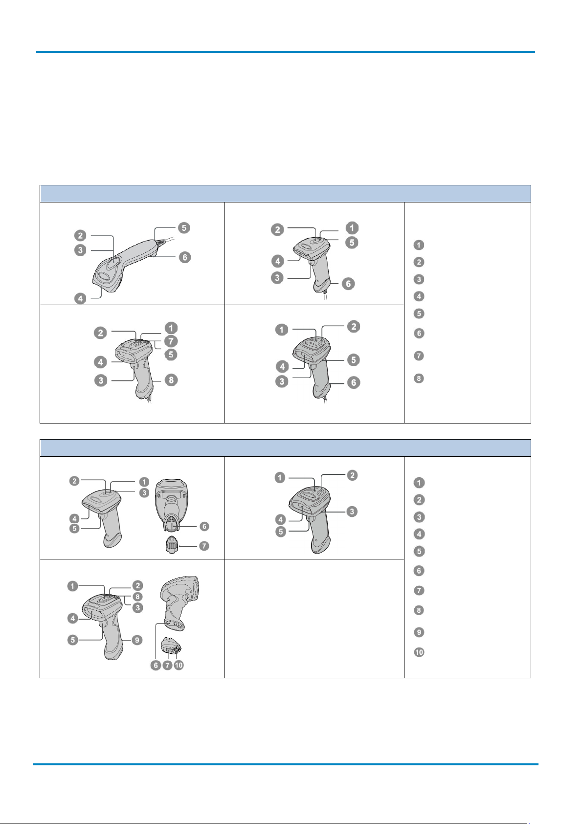
1 Getting familiar with your IDM Hand-held scanner
The IDM family includes 1D scanners with linear imagers and 2D scanners with area imagers. There are
Bluetooth and corded versions available. Furthermore there are different models for variant target
applications. IDMx2x and IDMx4x can be used for general purpose applications whereas IDMx6x is designed
for industrial environments.
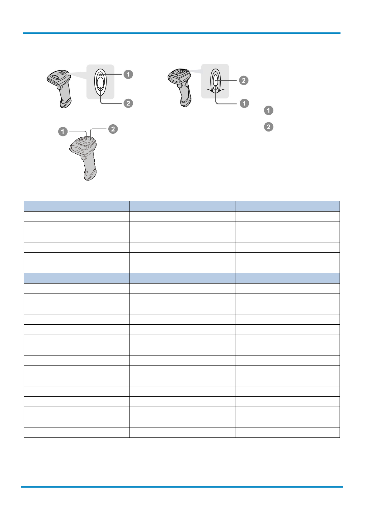
IDM120
IDM160/IDM260
IDM140
IDM240
Operating indicator
Status indicator
Trigger
Viewing window
Beeper
IDM141
IDM241
Connection indicator
IDM161/IDM261
Status indicator
Beeper
Reading window
Trigger
End Cap
Retaining screw
Page 7
Operating Instructions
Connectivity
IDM corded
8017159/142O/2019-05-23
© SICK AG · Germany · All rights reserved · Subject to change without notice
7
Paging/Reset
pushbutton
DC female connector
(power supply unit)
& IDM Bluetooth
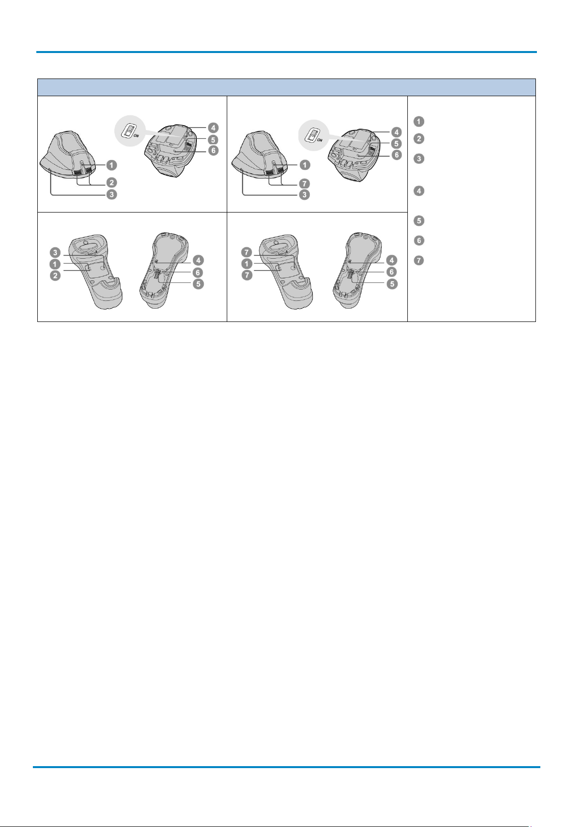
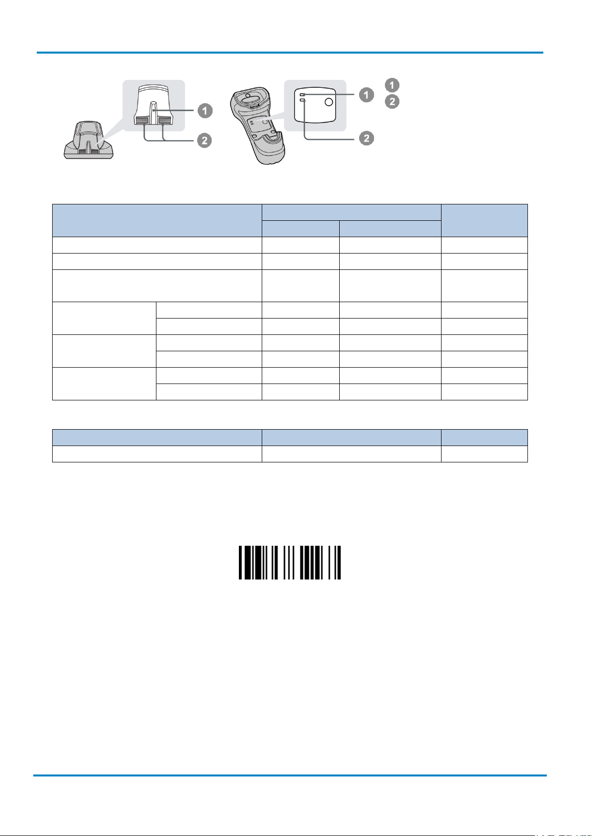
IDM Bluetooth Cradles
IDMx41 smart base station
IDMx41 charging station
Operating indicator
Status Indicators
USB bus power
switch
IDMx61 smart base station
IDMx61 charging station
Host interface
Reserved
Page 8
Connectivity
Operating Instructions
& IDM Bluetooth
8
© SICK AG · Germany · All rights reserved · Subject to change without notice
8017159/142O/2019-05-23
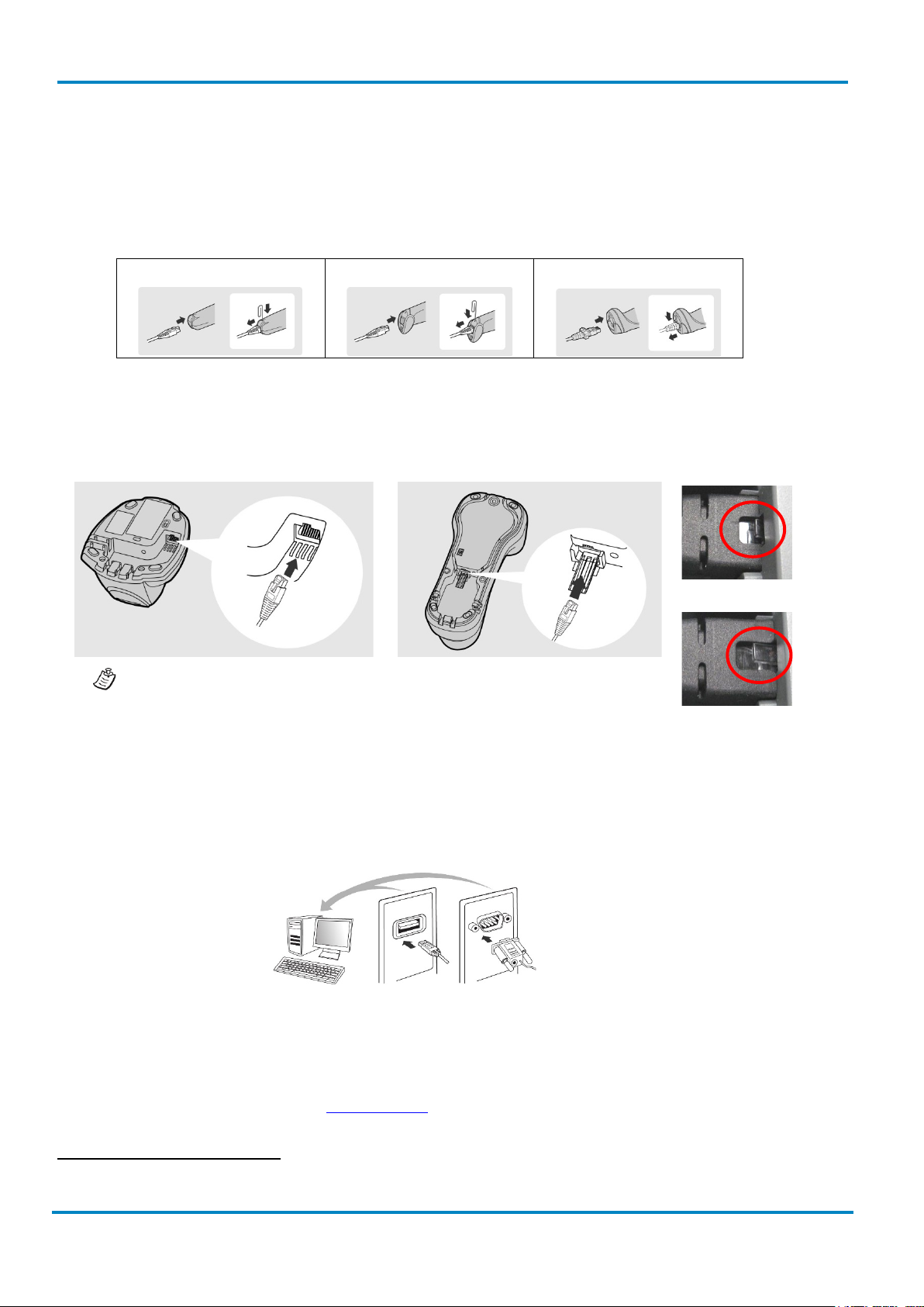
IDMx41: base cradle
IDMx61: base cradle
Correct:
Not correct:
cradle to secure the data transmission to the host.
RS-232
Serial
USB HID &
USB Com Port
IDM corded
1.1 Connectivity
To connect the scanner, plug the cable into the interface port of the scanner and connect it to the host. To
remove the cable, straighten one end of a paper clip and insert it into the cable release hole to pull out the
cable. For IDM160/260 series you need to push down the bracket of the enclosure clip and pull out the cable.
IDM120 Series
For IDM Bluetooth scanners the cable needs to be connected to the smart cradles. The cable inlet is on the
bottom side of the cradles.
IDM140/240 Series
IDM160/260 Series
Ensure that the cable is pushed all the way into the RJ inlet of the base
1.1.1 Standard Interfaces (RS-232, USB)
1
IDM scanners support USB
and RS-232 Serial interfaces.
• USB HID (Human Interface Device): The scanner works as a generic USB Keyboard.
• USB COM: The scanner works as a RS-232 serial device. Please note that you have to install the USB
COM Port driver (available on www.sick.com
) before use.
1
USB is not suitable for use in industrial environments. Therefore, at cable installation it is important to ensure that there are no close
sources of interference.
Page 9
Operating Instructions
Connectivity
IDM corded
8017159/142O/2019-05-23
© SICK AG · Germany · All rights reserved · Subject to change without notice
9
RS-2323 cable
Adapter cable
Connection
module
& IDM Bluetooth
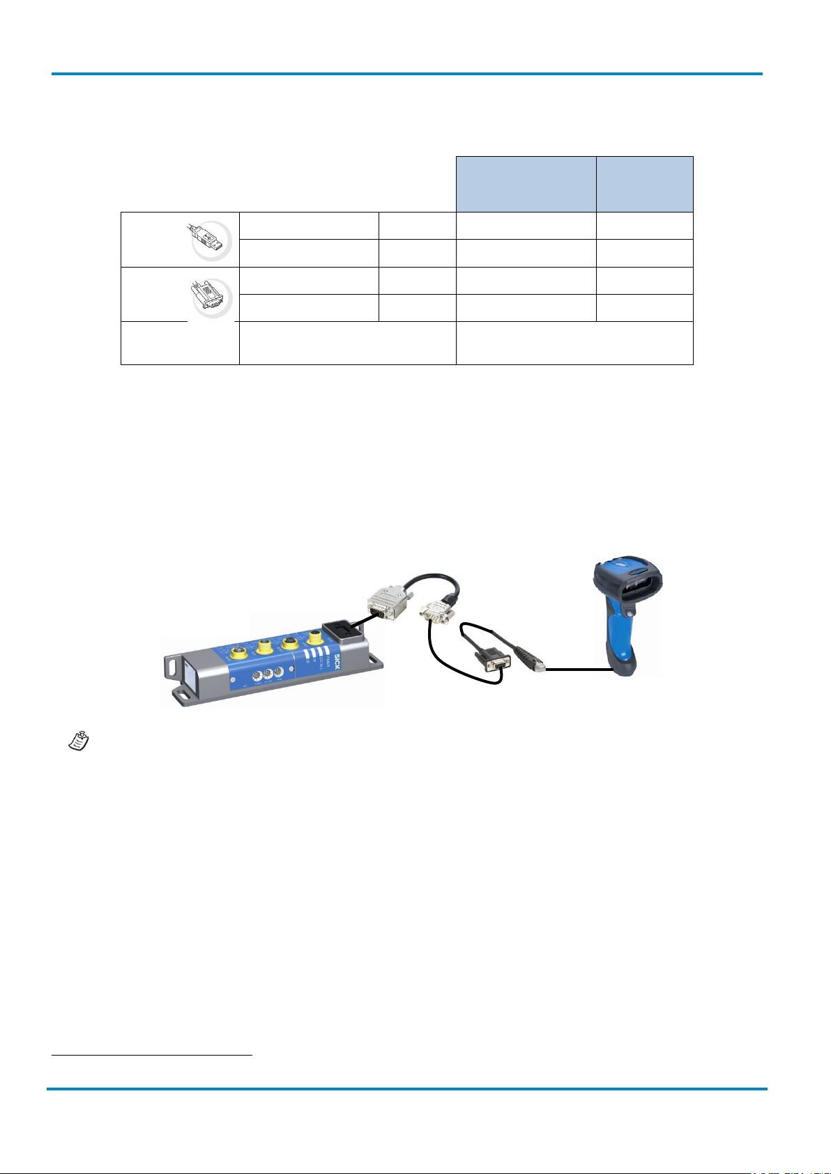
Depending on the Scanner model different cables are available.
IDM120, IDMx40,
IDM Bluetooth base
stations
IDM160,
IDM260
USB
RS-232
Power Supply
straight 1.8 m 6036728 6045195
spiral 3 m 6039158 6045232
straight 1.8 m 6041540 6045196
spiral 3 m 6039156 6045233
needed for operation with RS-232
1
cables
, Bluetooth
6036722
1.1.2 Industrial fieldbus
The IDM Hand-held scanners can be connected to industrial fieldbuses (such as PROFIBUS, PROFINET,
Ethernet TCP/IP, DeviceNet, etc.) via SICK connection modules and an adapter cable. The adapter cable
includes a voltage converter from DC 24 to 5 V for the voltage supply of the hand-held scanner, eliminating
the need of a separate power supply.
For more information on necessary components and order numbers please contact your local SICK
sales representative.
1
If there is no power on Pin 9.
Page 10

Technical Specifications
Operating Instructions
& IDM Bluetooth
10
© SICK AG · Germany · All rights reserved · Subject to change without notice
8017159/142O/2019-05-23
IDM corded
1.2 Technical Specifications
1.2.1 IDM Corded Hand-held Scanners
Type IDM120 IDM140 IDM160 IDM240 IDM260
Field of
application
Enclosure
rating
Supported
code types
Code
resolution
Reading
distance
(at code
resolution)
Interfaces
Optical
indicators
General Purpose General Purpose Industrial General Purpose Industrial
IP 41 IP 41 IP 65 IP 41 IP 65
1D, Stacked1 1D, Stacked, 2D 1D, Stacked, 2D2
≥0.102 mm
1)
≥0.076 mm
1)
≥0.07 mm1), ≥0.13 mm2)
SR model:
0 mm ... 400 mm
(0.102 mm)
1)
20 mm ... 850 mm
(0.5 mm)
1)
20 mm ... 850 mm
(0.5 mm)
1)
30 mm ... 400 mm (0.25 mm)
USB (Keyboard Wedge & Com Port Emulation), RS-232,
(Ethernet TCP/IP, PROFINET, PROFIBUS, DeviceNet)
1 LED
(good read)
2 LEDs (operational status, good read)
3
Vibration No No Yes No Yes
Acoustic
indicators
Operating
Voltage
Beeper, disengageable
5 V DC (+/- 5%)
2)
Max. 395 mA
(Vibrator disabled)
Max. 420 mA
(Vibrator enable)
Current
consumption
(Operating)
Typical
170 mA
Typical 180 mA
180 mA
(Vibrator disabled)
230 mA
(Vibrator enable)
Typical 395 mA
Current
consumption
Typical 75 mA Typical 80 mA Typical 80 mA Typical 220 mA Max. 220 mA
(Standby)
Light source LED: visible red light (630 nm)
Laser aimer No Yes (Laser Class 1)
Ambient
operating
0 °C ... 50 °C -10°C … 50°C -20 °C ... 50 °C -10 °C ... 50 °C -20 °C ... 50 °C
temperature
Storage
temperature
1)
Valid for Code 39, 2) Valid for Data Matrix
-20 °C ... 60 °C -40 °C ... 70 °C -30 °C ... 70 °C -40 °C ... 70 °C -40 °C ... 70 °C
1
Depending on scanner version (PDF version is necessary).
2
Depending on scanner version, option of low performance DPM Code reading can be enabled via Plug-in
3
Optional via external SICK connection modules.
Page 11

Operating Instructions
Technical Specifications
IDM corded
8017159/142O/2019-05-23
© SICK AG · Germany · All rights reserved · Subject to change without notice
11
& IDM Bluetooth
1.2.2 IDM Bluetooth Hand-held Scanners
Type IDM141 IDM161 IDM241 IDM261
Field of
General Purpose Industrial General Purpose Industrial
application
Enclosure rating IP 41 IP 65 IP 41 IP 65
Supported code
1D, Stacked1 1D, Stacked
1
1D, Stacked, 2D 1D, Stacked, 2D2
types
Code resolution ≥0.076 mm
Reading
distance
20 mm ... 850 mm
(0.5 mm)
1)
(at code
1)
≥0.076 mm
20 mm ... 850 mm (0.5
1)
mm)
1)
≥0.07 mm1), ≥0.13 mm2)
SR model:
30 mm ... 400 mm (0.25 mm)
resolution)
Interfaces
Bluetooth
USB (Keyboard Wedge & Com Port Emulation), RS-232,
(Ethernet TCP/IP, PROFINET, PROFIBUS, DeviceNet)
3
Bluetooth v 2.1 EDR, 2.4 ... 2.4835 GHz Bluetooth v 4.0, 2.402 … 2.4830 GHz
Protocol
Bluetooth
operating range
Optical
Up to 100 m (free view), Batch function for
expansion of the wireless radius
Up to 100 m (free view), Batch function for
expansion of the wireless radius
2 LEDs (good read, charge of battery, radio connection status)
indicators
Vibration No Yes No Yes
Acoustic
Beeper, disengageable
indicators
2)
Operating
5 V DC (+/- 5%)
Voltage
Current
consumption
(Operating)
Current
180 mA 230 mA (Vibrator enabled)
180 mA (Vibrator disabled)
750 mA
(charging incl.
750 mA (charging incl.
base station)
base station
80 mA 80 mA 175 mA 175 mA
consumption
(Standby)
Light source LED: visible red light (630 nm)
Laser aimer No Yes (Laser Class 1) No Yes (Laser Class 1)
Ambient
-10 °C ... 50 °C -20 °C ... 50 °C -10 °C ... 50 °C -20 °C ... 50 °C
operating
temperature
Storage
-40 °C ... 70 °C -30 °C ... 70 °C -40 °C ... 70 °C -40 °C ... 70 °C
temperature
1)
Valid for Code 39, 2) Valid for Data Matrix
For detailed technical specifications, see the Online Data Sheet on the product site on the web
(www.sick.com
).
1
Depending on scanner version (PDF version is necessary).
2
Depending on scanner version, option of low performance DPM Code reading can be enabled via Plug-in.
3
Optional via external SICK connection modules.
Page 12

Preparation before using
Operating Instructions
& IDM Bluetooth
12
© SICK AG · Germany · All rights reserved · Subject to change without notice
8017159/142O/2019-05-23
IDMx4x: General Purpose series
IDMx6x: Industrial series
IDM corded
2 IDM Bluetooth Scanners
2.1 Preparation before using
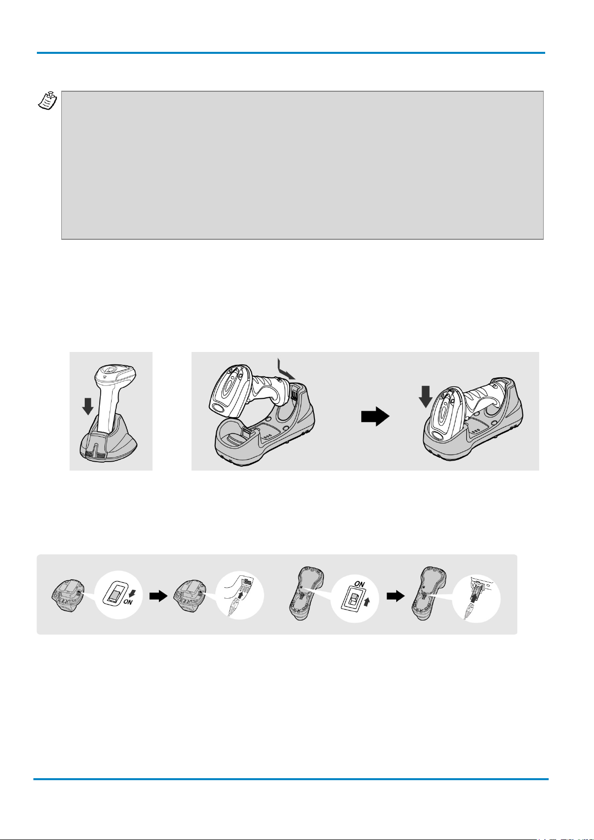
2.1.1 Battery installation
1. Ensure the battery contacts of the battery pack are facing the charging contacts inside the battery
cavity.
2. Slide the battery pack into the battery cavity until hearing a click sound before locking it with the end
cap. The scanner will give 4 beeps when the battery pack is installed properly if the battery pack still
has power.
3. Secure the end cap with the screw provided.
You can use the overlapping battery label to pull out the battery if needed.
2.1.2 Charging the battery
1. Choose an appropriate plug for your country and slide it into the power adapter cavity until it is locked.
Then plug the AC power plug into the AC wall socket.
Please make sure the USB bus power switch is in “OFF” position.
2.
3. Plug the DC power cord of the power supply unit into the DC Jack of the cradle. The smart cradle emits
the power-on beeps and the central (IDMx4x)/ upper (IDMx6x) power indicator gives one blue blink. If
you use the charging cradle, the central (IDMx4x)/ upper (IDMx6x) power indicator turns steady blue.
4. Place the scanner on the cradle. The status indicator of scanner will turn steady red if the battery is
not fully charged. When the battery is fully charged, the status indicator of the scanner turns steady
green.
Please note the important battery information on the next page!
Page 13
Operating Instructions
Preparation before using
IDM corded
8017159/142O/2019-05-23
© SICK AG · Germany · All rights reserved · Subject to change without notice
13
vertically
Afterwards push the scanner head down.
Important information: Please charge the new battery pack for 8 hours prior to the first use. Ensure
destruction of the battery.
& IDM Bluetooth
that you are using a battery with enough capacity. Otherwise the scanner might lose its radio
connection. As soon as the scanner gives warning messages (one red blink and one beep at a regular
interval) the scanner needs to be recharged. If the scanner gives 8 red blinks and 8 beeps, the battery
power is extremely low. In that case the battery needs to be recharged immediately! If the scanner is
not placed into the charging cradle right the way, the scanner turns off automatically. Due to an internal
protection circuit there will now be measured 0 V on the outside contacts of the battery. If the battery
is not recharged immediately, a further discharge takes place even though the scanner is turned off.
Due to the internal chemical processes of lithium ion batteries, this will then result in an irreversible
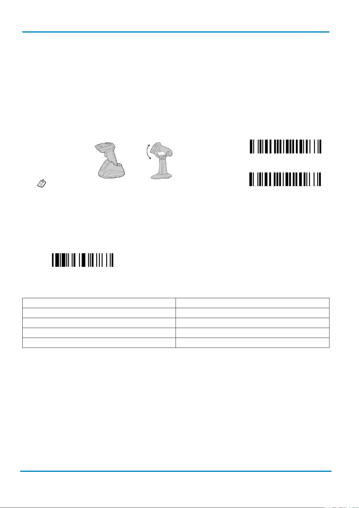
2.1.3 Placing the scanner into the cradle
Ensure that the scanner is placed properly into the respective smart or charging cradle. If the unit is not
placed correctly into the cradle, the charging might not start.
IDMx41: Insert the scanner
IDMx61: Insert the back of the scanner first.
The correct placement into the cradle can be verified by the charging LED on the scanner. (See also chapter
2.1.5 on page 14)
2.1.4 USB Bus power
• If USB 3.0 is available in your host device, both battery charging and regular operation can be
supported by the USB Bus Power without using external power supply.
• If you want to use this feature, set the USB bus power switch to “ON”. Then connect the cradle and
host device via an USB cable.
• If only USB 2.0 is available in your host device the external power supply is necessary as a power
source, because the power supplied from USB 2.0 is not enough to support both battery charging and
regular operation simultaneously.
Page 14
Preparation before using
Operating Instructions
& IDM Bluetooth
14
© SICK AG · Germany · All rights reserved · Subject to change without notice
8017159/142O/2019-05-23
IDM141
IDM161/IDM261
IDM241
Description
Link indicator
Beeper
Radio connection
1 blue blink per 2.5 sec.
Off
Radio disconnection
3 blue blinks per 2 sec.
Off
During connection
Quick blue blinks
Short clicks
Radio connection built
1 blue blink per 2.5 sec.
4 beeps in ascending tone
Radio connection lost
3 blue blinks per 2 sec.
4 beeps in descending tone
Data Transmission
Quick blue blink
Short clicks
Description
Status Indicator
Beeper
Under charging (on cradle)
Steady red
Off
Fully charged (on cradle)
Steady green
Off
Under batch scanning
1 green blink per 2.5 sec.
Off
Pair failure
Steady red
2 Di-do Di-do beeps
Out of memory
2 red blinks
2 long beeps
Battery power low
1 red blink at regular interval
1 beep at regular interval
Battery power extremely low
1 red blink
8 beeps
Good read
1 green blink
1 good read beep
Under Configuration
Steady red
Off
Uninstall state
Alternative red and green blinks
Off
Upgrade state
Steady red
Short click
Time out warning
Off
3 long beeps
Paged by smart cradle
Off
6 page beeps
Sleep state / Battery no power
Off
Off
Power Off
Off
Off
Link Indicator
2.1.5 Indications
IDM Bluetooth Scanners
IDM corded
Status Indicator
Page 15
Operating Instructions
Paging Function
IDM corded
8017159/142O/2019-05-23
© SICK AG · Germany · All rights reserved · Subject to change without notice
15
IDM Smart Cradle
Indicators
Power
Status
Power on
1 blue blink
Off
Power on beeps
Smart Cradle Upgrade State
Off
Steady red
Short clicks
green blinks
Radio Connected
Steady blue
Steady Green
Off
Radio Disconnected
Off
Steady red
Off
Radio Connected
Steady blue
Off
Off
Radio Disconnected
Off
Steady red
Off
PICO Mode
Steady blue
Steady green
6 page beeps
PAIR Mode
Steady blue
Off
6 page beeps
IDM Charging Cradle
Description
Power Indicator
Beeper
Power on
Steady blue
Off
Paging
Power indicator
& IDM Bluetooth
Status indicator(s)
Description
Uninstall state Off Alternative red-
PICO Mode
PAIR Mode
Smart cradle paged
by scanner
2.2 Paging Function
Beeper
Off
The paging function helps to locate the paired smart cradle or scanner. If you would like to page the paired
smart cradle, you can scan the “Paging” command.
If you would like to page the paired scanner, you can press the paging/rest button of the smart cradle no
longer than 5 seconds.
2.3 Radio Link Mode
The IDM Bluetooth scanners provide several radio link modes to communicate with the host device. When the
Bluetooth-enabled host device is not available, the scanner can work with the smart cradle in PAIR mode
(peer-to-peer connection) or PICO mode (multiple connections) to provide a plug-and-play cordless migration
of your existing non-Bluetooth devices. Moreover, you are able to use the scanner to work with Bluetoothenabled host devices via SPP mode or HID mode. When the radio link is disconnected, the scanner is capable
of reconnecting the radio link automatically when it returns into the Bluetooth radio range area. Please note
Page 16

Radio Link Mode
Operating Instructions
& IDM Bluetooth
16
© SICK AG · Germany · All rights reserved · Subject to change without notice
8017159/142O/2019-05-23
Uninstall
PAIR Mode
IDM corded
that this feature is not available in SPP slave mode. If you would like to change the radio link mode, please
scan the “Uninstall” command to reset the scanner to the uninstall state.
2.3.1 PAIR Mode
In PAIR mode, one smart cradle will work with one scanner. The smart cradle does not only provide the
Bluetooth radio link with the scanner, but also offers the legacy cabled interfaces to the host device, including
USB HID, USB COM, and RS-232 serial.
Use IDM Hand-held scanner in PAIR Mode:
1. Ensure the battery is fully charged. Refer to the section of “2.1.2 Charging the battery” for details.
2. Choose the interface cable, plug it into the smart cradle and connect it to the host device. (Refer to
chapter “1.1 Connectivity” for details.)
3. Turn on the power of your host device.
4. Note that if the scanner is shipped together with a smart cradle, they are pre-paired already. You will
see the link indicator of the scanner shows 1 blue blink per 2.5 seconds and the central (IDMx41)/
upper (IDMx61) power indicator of the smart cradle turns steady blue. If the scanner and smart cradle
just give alternative red and green blinks (“Uninstall” state), please follow step 5 to establish the
connection between scanner and smart cradle.
5. Scan the “PAIR mode” command. The status indicator of the scanner will turn steady red immediately.
Place the scanner into the smart cradle. You will hear one short beep to indicate the activation of the
pairing process. The scanner will emit continuous short clicks and the link indicator of the scanner will
flash blue quickly during the pairing process. When you hear 4 beeps in ascending tone, the pairing
process is completed. You will see that the link indicator of the scanner gives 1 blue blink per 2.5
seconds and the central (IDMx41)/ upper (IDMx61) power indicator of the smart cradle turns steady
blue. If the scanner pairing process failed or if the scanner is not placed into the smart cradle within
20 seconds, you will hear 2 “Di-do Di-do” beeps indicating that the pairing process was not successful.
The scanner will return to the uninstall state automatically.
6. Scan the corresponding host interface quick set command (chapter 5.7) to complete the installation.
The default host interface of the smart cradle is preset to USB HID. If you want to set the host interface to
USB COM you need to install the USB COM Port driver (available on www.sick.com
) before using.
2.3.2 PICO Mode
In PICO mode up to 7 scanners can be connected to one smart cradle. If you would like to un-pair all scanners
paired with the smart cradle, please press and hold the paging/reset button of the smart cradle for more than
5 seconds. If you just want to un-pair part of the paired scanners, please take those paired scanners and scan
the “Uninstall” command.
Page 17

Operating Instructions
Radio Link Mode
IDM corded
8017159/142O/2019-05-23
© SICK AG · Germany · All rights reserved · Subject to change without notice
17
Uninstall
PICO Mode
& IDM Bluetooth
Use IDM Hand-held scanner in PICO Mode:
1. Ensure the battery is fully charged. You may refer to the section of “2.1.2 Charging the battery” for
details.
2. Choose the interface cable, plug it into the smart cradle and connect it to the host device. (Refer to
chapter “1.1 Connectivity” for details.
3. Turn on the power of your host device.
4. Ensure the side (IDMx41)/ lower (IDMx61) status indicators of the smart cradle shows alternative red
and green blinks (“Uninstall” state). If the smart cradle is paired with other scanners press and hold
the paging/ rest button for more than 5 seconds to un-pair all paired scanners. This way the smart
cradle will return to uninstall state automatically.
5. Prepare the scanners you would like to pair with the smart cradle. Ensure that the status indicator of
each scanner gives alternative red and green blinks (“Uninstall state”). If the scanner is no in the
“Uninstall state”, scan the “Uninstall” command to un-pair the scanner, then scan the “PICO Mode”
command. The status indicator of the scanner will turn to steady red.
Place the scanner into the smart cradle. You will hear one short beep to indicate the activation of the
pairing process. The scanner will emit continuous short clicks and the link indicator of the scanner will
flash blue quickly during the pairing process. When you hear 4 beeps in ascending tone, the pairing
process is completed. You will see that the link indicator of the scanner shows 1 blue blink per 2.5
seconds. The central (IDMx41)/ upper (IDMx61) power indicator of the smart cradle turns steady blue
and the side (IDMx41)/ lower (IDMx61) status indicators turn steady green.
If the scanner pairing process failed or if the scanner is not placed into the smart cradle within 20
seconds, you will hear 2 “Di-do Di-do” beeps to warn the failure of pairing. The scanner will return to
the uninstall state automatically.
6. Scan the corresponding host interface quick set command to complete the installation.
7. Repeat the same procedure to pair other scanners (up to seven scanners in total) with the smart
cradle.
For the user’s convenience, the smart cradle will automatically assign an ID number to each scanner.
Scan the “System Information” command to check the assigned ID number of each scanner.
Clone Function
For the user’s convenience, the clone function will help you to clone the host interface related parameters
(please refer to the following table for details) from one of the paired scanners to the rest of the paired
scanners under PICO mode. You can use one of the paired scanners to set the host interface related
parameters first and then scan the “Save Configuration” command. Afterwards, please take the other paired
scanners to scan the “Clone” command one by one to clone the host interface related parameters.
Page 18

Radio Link Mode
Operating Instructions
& IDM Bluetooth
18
© SICK AG · Germany · All rights reserved · Subject to change without notice
8017159/142O/2019-05-23
Save Configuration
Clone
Field Delimiter
Data Transmission Format
Host Interface Control
Host interface Selection
Keyboard Layout
Intermessage Delay
Interfunction Delay
Intercharacter Delay
Caps Lock Control
Caps Lock Release Control
Function Key Emulation
Key Pad Emulation
Upper/Lower Case
Handshaking Protocol
Intermessage Delay
Interfunction Delay
Intercharacter Delay
Baud Rate
Data Frame
Time Out Control
Output Polarity
Initial Signal State
Margin Time
Module Time
Narrow/Wide Ratio
Code39 Emulation
IDM corded
For using the Clone function, the paired scanners need to stay connected. The host interface related
parameters can’t be cloned to the paired scanner in disconnected status.
The below host interface related parameters will be impacted by the cloning function:
Data Transmission Parameter
Keyboard Interface Control
Serial Interface Control
Wand Emulation Control
2.3.3 HID Mode
Through the HID service, the scanner can work as a Bluetooth Keyboard. In this mode, the scanner will be
discoverable by the radio connection request issued by the remote host device. In some cases, you may be
requested to enter the Passkey (PIN) to establish the Bluetooth connection for security purpose.
Page 19

Operating Instructions
Radio Link Mode
IDM corded
8017159/142O/2019-05-23
© SICK AG · Germany · All rights reserved · Subject to change without notice
19
Uninstall
HID Mode
HID Legacy Mode
HID Mode with Passkey
& IDM Bluetooth
Use IDM Hand-held scanner in HID Mode:
1. Ensure the battery is fully charged. You may refer to the section of “2.1.2 Charging the battery” for
details.
2. Power on the scanner within radio range.
3. Ensure the status indicator of the scanner gives alternative red and green blinks (“Uninstall” state). If
the scanner is not in uninstall state scan the “Uninstall” command first.
4. If your remote host is equipped with the latest Bluetooth drivers or if it is an iOS or Android device we
recommend to use “HID Mode” for quick pairing. If necessary you may use “HID Mode with Passkey”
to establish a more secure connection. If you experience problems in “HID Mode” try “HID Legacy
Mode” instead.
5. Once you scan one of the above commands the link indicator of the scanner will give 3 blue blinks per
2 seconds during the searching process. You have to execute the Bluetooth Discovery procedure to
find available Bluetooth devices. Select “IDMxxx”.
6. If you use “HID Mode” go to step 9.
7. If you use “HID Mode with Passkey” you will be requested to enter the passkey (PIN) on the remote
host. Please enter the passkey (PIN) accordingly by scanning the “Option Codes” on page 132 and
then scan “FIN (Finish)” to end the passkey entry. Continue with step 9.
8. If you scan “HID Legacy Mode” the passkey (PIN) may be requested. Please enter “00000000”
(default setting). You will see “Keyboard on IDMxxx”. Double-click this HID service to establish the
connection between the scanner and the remote host device.
9. The scanner will emit 4 beeps in ascending tone to indicate the radio is connected. At the same time,
the link indicator of the scanner will give 1 blue blink per 2.5 seconds to indicate the scanner is in
radio-connected state. Please note that if the scanner failed to connect to the host device within 30
seconds, the link indicator will give 3 blue blinks per 2 seconds. But the scanner is still continuing to
discover the host device for another 30 seconds before going to sleep mode. In the interim, you still
can scan “Uninstall” command to revert the scanner to uninstall state. If the scanner goes to sleep
mode, you need to press the trigger to wake up the scanner to continue the installation.
The above procedures are based on popular Windows environment. However, the installation
procedure may vary depending on different remote host devices, operating systems and the Bluetooth
drivers.
Page 20

Radio Link Mode
Operating Instructions
& IDM Bluetooth
20
© SICK AG · Germany · All rights reserved · Subject to change without notice
8017159/142O/2019-05-23
Uninstall
SSP Master Mode
IDM corded
While using HID mode be aware of potential error in the data transmission when radio link quality is
poor. You are suggested to use the scanner under the communication coverage at all times.
2.3.4 SSP Master/ Slave Mode
Through the standard SPP service, the scanner can work as a Bluetooth Serial Device. In SPP Master Mode,
the scanner initiates the radio connection request to the remote slave device. In SPP slave mode, the scanner
will be discoverable by the radio connection request issued by the remote host device.
Establish SSP Master Connection
1. Ensure the battery is fully charged. Open the folder “Hardware” located in Bluetooth Advanced Setting
of the remote host device to check its device MAC address. Then prepare a 12-character Code 128
barcode of the remote host device MAC address, or follow the step 4 to input MAC address by
scanning 12 option codes.
2. Ensure a virtual COM port is available in your remote host for connecting the scanner. If not, please
open the folder “Local Services” located in Bluetooth Advanced Setting. Click the “Add Serial Services”
to add one more Bluetooth COM port.
3. Power on the scanner within radio coverage and ensure the status indicator of the scanner gives
alternative red and green blinks (“Uninstall” state). If the scanner is not in uninstall state, please scan
the “Uninstall” command first, and then scan the “SPP Master Mode” command. The status indicator
of the scanner will turn steady red immediately.
4. Scan a 12-character MAC address barcode, or scan 12 option codes and “FIN” command to confirm
your inputs. The scanner will emit continuous short clicks and the link indicator of the scanner will
flash blue quickly during the radio connecting process. If the PIN Code or Passkey is requested, please
enter “00000000” (default setting).
5. The scanner will emit 4 beeps in ascending tone to indicate the radio is connected. At the same time,
the link indicator of the scanner will give 1 blue blink per 2.5 seconds to indicate the scanner is in
radio-connected state. Please note that if the scanner failed to connect to the host device within 30
seconds, the link indicator will give 3 blue blinks per 2 seconds. But the scanner is still continuing to
discover the host device for another 30 seconds before go to sleep. In the interim, you still can scan
the “Uninstall” command to revert the scanner to uninstall state. If the scanner is already in sleep
mode, you just need to press the trigger to wake up the scanner to continue the installation.
The above procedures are based on popular Windows environment. However, the installation
procedure may vary depending on different remote host devices, operating systems and the Bluetooth
drivers.
Page 21

Operating Instructions
Out-of-Range Scanning
IDM corded
8017159/142O/2019-05-23
© SICK AG · Germany · All rights reserved · Subject to change without notice
21
Uninstall
SSP Slave Mode
Enable Out-of-Range Scanning
Disable Out-of-Range Scanning
& IDM Bluetooth
Establish SSP Slave Connection
1. Ensure the battery is fully charged and a virtual COM port is available in your remote host for
connecting the scanner. If not, please open the folder “Client Applications” located in Bluetooth
Advanced Setting. Click the “Add COM Port” to add one more Bluetooth COM port.
2. Power on the scanner within radio coverage and ensure the status indicator of scanner gives
alternative red and green blinks (in “Uninstall” state). If the scanner is not in uninstall state, please
scan the “Uninstall” command first. Then scan the “SPP Slave Mode” command, and the link indicator
of scanner will give 3 blue blinks per 2 seconds during searching process.
3. Execute the Bluetooth Discovery procedure to find all available Bluetooth device list in your remote
host. You will see “IDMxxx” is shown in the list if the scanner is successfully discovered.
4. Double click the “IDMxxx” on the discovered Bluetooth devices. If the PIN Code or Passkey is
requested for security connection, please enter “00000000” (default setting). You will see “Serial Port
on IDMxxx”. Please double click this SPP service to establish the connection between scanner and
remote host device.
5. The scanner will emit 4 beeps in ascending tone to indicate the radio is connected. At the same time,
the link indicator of the scanner will give 1 blue blink per 2.5 seconds to indicate the scanner is in
radio-connected state. Please note that if the scanner is not connected to the host device within 1
minute after scanning the “SPP Slave Mode” command, the scanner will go to sleep mode
automatically. You can just press the trigger to wake up the scanner to continue the installation.
The above procedures are based on popular Windows environment. However, the installation
procedure may vary depending on different remote host devices, operating systems and the Bluetooth
drivers.
2.4 Out-of-Range Scanning
When the radio connection is established between scanner and remote host device, the scanner will transmit
each scanned code content right after scanning the barcode. However, the scanner is preset not to scan any
barcode data when it loses the radio connection with the remote host device.
If you enable the Out-of-Range scanning function, the scanner can continue scanning barcode data while it is
out of radio coverage. All scanned data will be temporarily stored in the memory buffer until radio link
resumed.
If the scanner is out of radio coverage, you will hear 4 beeps in descending tone to indicate the loss of radio
connection. The link indicator of the scanner will give 3 blue blinks per 2 seconds. Once the scanner is back
Page 22
Presentation Scanning
Operating Instructions
& IDM Bluetooth
22
© SICK AG · Germany · All rights reserved · Subject to change without notice
8017159/142O/2019-05-23
Disable Auto-sense
Enable Auto-sense
Check Battery Status
IDM241-3 / IDM261-3: 1.00.01 and above
LED Indication
Battery Status
3 green and blue flashes
More than 75%
3 green flashes
More than 50%
3 orange flashes
More than 25%
3 red flashes
Less than 25%
IDM corded
to radio coverage, you will hear 4 beeps in ascending tone to indicate the radio connection is rebuilt and the
scanner will give 1 blue blink per 2.5 seconds. At the same time, all stored scanned data will be transmitted
automatically right after the radio link is resumed.
2.5 Presentation Scanning
The Presentation Scanning is designed for hand-free applications. If the “Presentation Scanning Auto-sense”
function is enabled, the scanner is capable of automatically switching to presentation mode as soon as you
place the scanner onto the Presentation Stand or into Smart Cradle.
Presentation scanning on cradle is only available for IDMx41
series.
2.6 Battery status (IDM Bluetooth only)
You can check battery status of the scanner by short pressing the Left Key or scanning “Check Battery Status”
command.
The following corresponding flashes of the LED indicators present the current battery status of the scanner.
Available Firmware:
IDM141-3 / IDM161-3: 4.00.05 and above
IDM241-1 / IDM261-1: 2.00.03 and above
2.7 Sleep Mode & Power Off
The scanner is preset to enter “Sleep Mode” if the scanner is not used after time-out duration. When the
scanner is under sleep mode, it is preset to enter “Power Off” automatically if it will not be waked up after
time-out duration.
Page 23

Operating Instructions
Batch Scanning (Inventory Mode)
IDM corded
8017159/142O/2019-05-23
© SICK AG · Germany · All rights reserved · Subject to change without notice
23
Sleep Mode
Power Off
Enter Batch Scanning
Exit Batch Scanning
Quantity 0
Quantity 5
Quantity 3
Quantity 8
Quantity 1
Quantity 6
Quantity 4
Quantity 9
Quantity 2
Quantity 7
& IDM Bluetooth
If you want your scanner to enter “Sleep Mode” or “Power Off” immediately, please scan the “Sleep Mode” or
“Power Off” command. The scanner can be waked up by pressing the trigger button.
2.8 Batch Scanning (Inventory Mode)
With the help of the Batch Scanning function, the scanner is capable of storing the barcode data of up to
100,000 EAN-13 barcodes. This functionality is often used for inventory applications.
Once you scan the “Enter Batch Scanning” command to activate this function, all scanned barcode data will
be stored into the memory storage and the status indicator of scanner will give green blink at regular interval
during batch scanning. You can scan and store the barcode data till the memory storage is full. If the storage
is full, you will hear 2 long beeps and the status indicator will give 2 red blinks to indicate out of storage. To
terminate the batch scanning, please scan the “Exit Batch Scanning” command.
2.8.1 Quantity feature
The scanner supports quantity feature when it enters batch scanning. When you use quantity feature, the
quantity information and scanned barcode data will be stored into the memory storage together. You can
enter the quantity information from 1 to 9999 by scanning the following quantity commands right after you
scanned the barcode data.
Page 24

Batch Scanning (Inventory Mode)
Operating Instructions
& IDM Bluetooth
24
© SICK AG · Germany · All rights reserved · Subject to change without notice
8017159/142O/2019-05-23
As many times as the quantity indicates
<Field delimiter><Quantity><Scanned data>
<Scanned data><Field delimiter><Quantity>
IDM corded
2.8.2 Data output format
There are three ways to output the stored barcode data and quantity information. The preset output format is
to transmit stored data as many times as the quantity indicates. But you still can set the scanner to output
stored barcode data together with quantity information in two fields, and a preset delimiter (“,”) will be output
in between. To fulfill different application requirements, both the delimiter and the output sequence can be
changed.
Page 25

Operating Instructions
Batch Scanning (Inventory Mode)
IDM corded
8017159/142O/2019-05-23
© SICK AG · Germany · All rights reserved · Subject to change without notice
25
Transmit stored data
Scan Barcode Command
Place scanner onto the cradle
Scan command or place scanner onto the cradle
Delete last scanned data
Clear all Stored Data
& IDM Bluetooth
2.8.3 Transmit stored data
The scanner is preset to transmit all the stored data by scanning the “Transmit Stored Data” command.
During the transmission, the scanner will emit continuous short clicks and the link indicator will blink blue.
Then the scanner will give two short beeps after data transmission is completed.
You are still able to set the scanner to transmit the stored data by placing the scanner onto the cradle as well.
2.8.4 Delete data
If a wrong barcode was scanned, the “Delete Last Scanned Data’’ command is helpful to recover mistakes. By
scanning the ‘’Delete Last Scanned Data’’ command, the last stored data can be deleted.
The scanner is preset to keep all the stored data until you scan the “Clear All Stored Data” command.
However you are also able to change the setting to “Auto Delete Stored Data after transmission”. (Refer to
chapter 3.10.3)
Page 26

Programming Commands
Operating Instructions
& IDM Bluetooth
26
© SICK AG · Germany · All rights reserved · Subject to change without notice
8017159/142O/2019-05-23
IDM corded
3 Configuration via Barcodes
3.1 Programming Commands
The IDM scanner bar code commands are specially designed proprietary bar code labels which allow you to
set the IDM Scanner’s internal programming parameters. There are System Command, Family Code and
Option Code for programming purpose.
Each programmable family and bar code command label is listed on the same page with major system
commands. The detailed explanations and special programming flowchart are printed on facing or following
pages. The Option Codes and System Commands can be found in the appendix on page 128 and 130.
3.1.1 System Command
The System Command is the highest level bar code command which directs the IDM Scanner to perform
immediate operations, such as entering programming mode (PROGRAM), exiting programming mode (EXIT),
listing system information (SYSLIST), recovering to factory preset configurations (M_DEFAULT) and so on.
Please note that all system commands will take a few seconds to complete the operations. User must wait for
the completion beeps before scanning another bar code.
3.1.2 Family Code
The Family Code is scanned to select the user desired programming family. IDM Scanner has already provided
more than one hundred programming families to meet any specific requirements.
3.1.3 Option Code
The Option Codes is a set of bar code commands represented by “0–9”, “A–F” and finishing selection (FIN).
For most setting, you must select at least one option code following the family code selection to set the
desired parameter for the selected programming family. The Option Codes can be found on page 128.
3.2 Programming Procedures
As you scan the bar code command to select the desired parameters, information about the final selected
parameters represented by the bar code commands are stored in the Hand-held scanner’s internal Flash
Memory ASIC or non-volatile memory. If you turn off the unit, the Flash Memory ASIC or non-volatile memory
retains all programming options. You don’t need to re-program the IDM Scanner if you want to keep the
existing configurations in the next power on.
The programming procedures of the IDM Scanner are designed as simple as possible for ease of setting. Most
programming families take the “Single Scan Selection” programming procedure. But several programming
families have more complex and flexible programmable options, and you must take “Multiple Scan Selection”,
“Cycling Scan Selection” or “Dual Level Selection” to complete their programming procedures. Each kind of
programming procedure is listed in the following pages for your reference. Please give careful attention to
become familiar with each programming procedure.
Page 27
Operating Instructions
Programming Procedures
IDM corded
8017159/142O/2019-05-23
© SICK AG · Germany · All rights reserved · Subject to change without notice
27
„PROGRAM“
beeping.
„END“
& IDM Bluetooth
If the programming family must take “Multiple Scan Selection”, “Cycling Scan Selection”, or “Dual Level
Selection” procedures, the family of the programming menu will be marked with the matched representing
symbol of Programming Category (P.C.) listed in the following table.
Conventions Descriptions
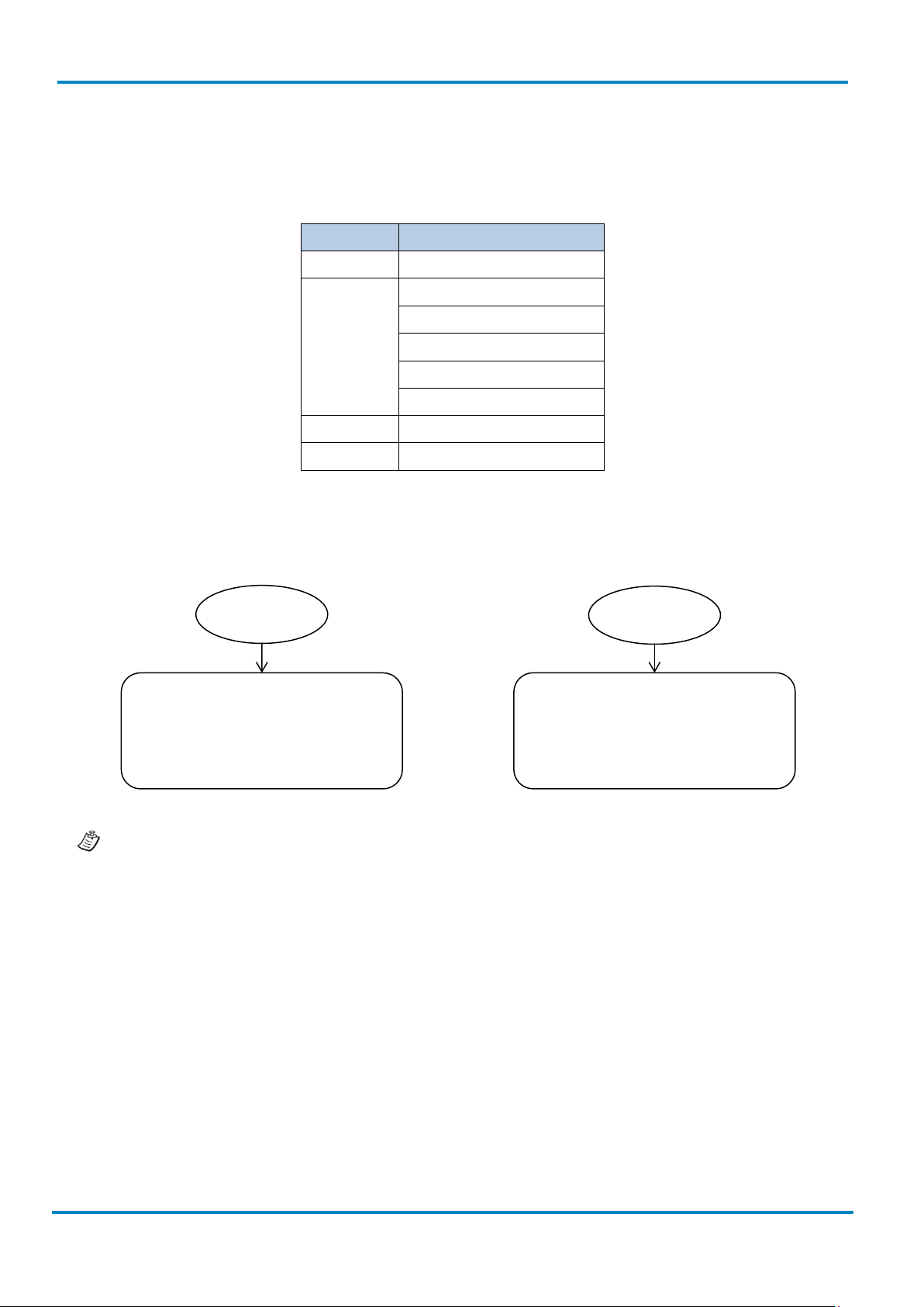
3.2.1 Program & End
The scanner will enter programming
mode and inhibit all non-
programming functions.
Scan
P.C.
( )
[ ] Selectable option code
Factory default value
Programming category
SS: Single scan selection
MS: Multiple scan selection
CS: Cycling scan selection
DS: Dual level scan selection
Necessary option code
The scanner will exit programming
mode, and store all parameters in
Flash Memory ASIC or non-volatile
memory, then issue the completion
Scan
Please note that the IDM Scanner will take 3-4 seconds to store parameters in internal Flash Memory
ASIC or non-volatile memory after you scan the “END”. Please don’t turn off the power before the
completion beeping. It may destroy all configured parameters.
Page 28
Programming Procedures
Operating Instructions
& IDM Bluetooth
28
© SICK AG · Germany · All rights reserved · Subject to change without notice
8017159/142O/2019-05-23
„M_DEFAULT
„SYSLIST“
Scan one of family
codes
Scan
„PROGRAM“
Scan one of option
codes
Scan
„END“
Yes
No
Enter Programming mode.
family.
parameter.
programming family?
Exit programming mode.
3.2.2 System List & Master Default
IDM corded
The scanner will list the product
information and revision number to
host via selected host interface,
then issue the completion beeping.
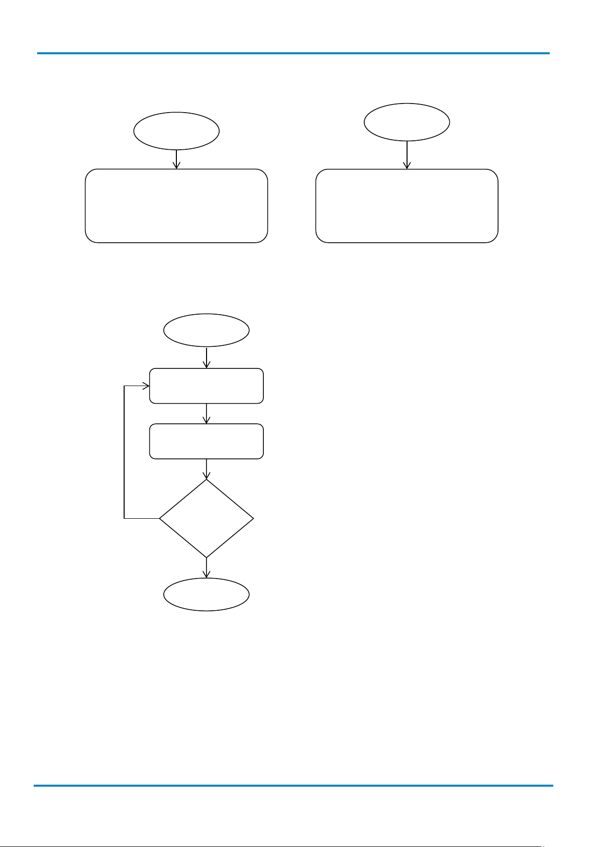
3.2.3 Single Scan
Scan
Repeat
selection
The scanner will recover all
programmable parameters into
factory preset configurations and
Select the desired programming
Select one option code for the desired
Do you want to select another
then issue the completion beeping.
Scan
Page 29
Operating Instructions
Programming Procedures
IDM corded
8017159/142O/2019-05-23
© SICK AG · Germany · All rights reserved · Subject to change without notice
29
Scan one of family
codes
Scan
„PROGRAM“
Scan one or several
option codes
Scan
„END“
Yes
No
Enter Programming mode.
family.
terminate the option code selection.
programming family?
Exit programming mode.
& IDM Bluetooth
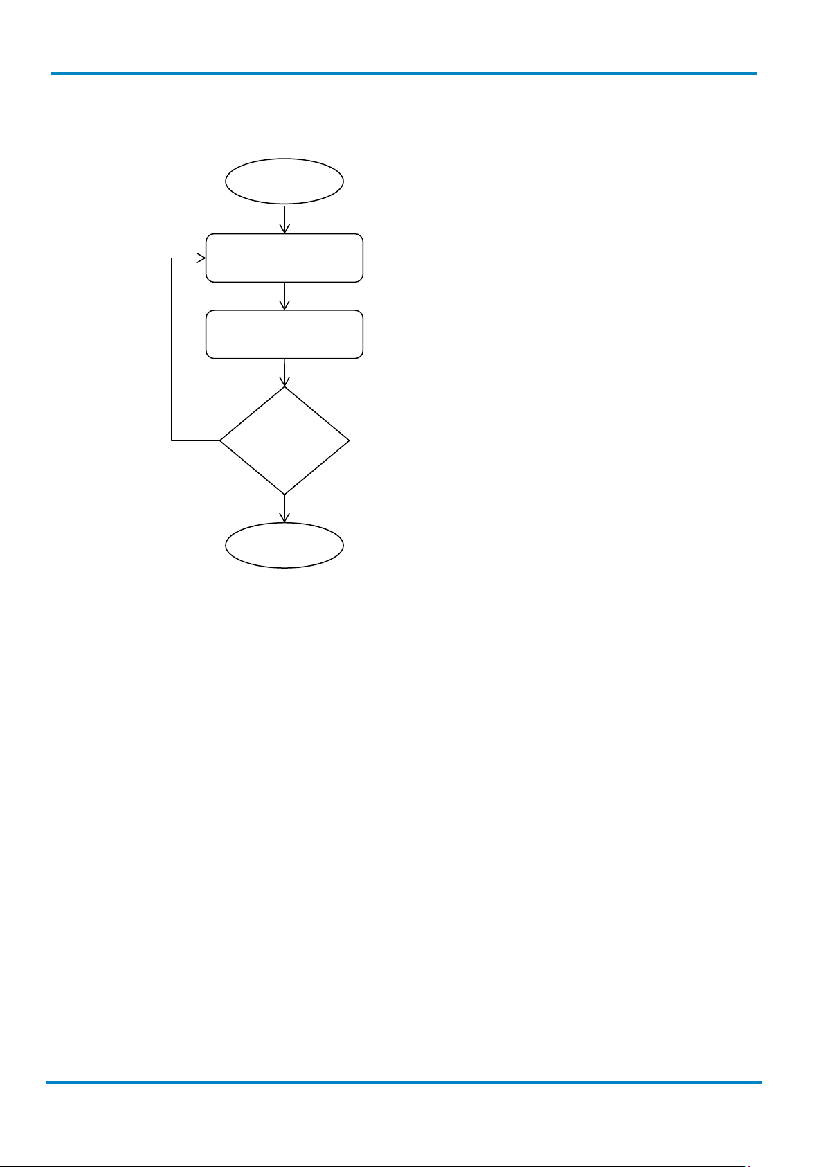
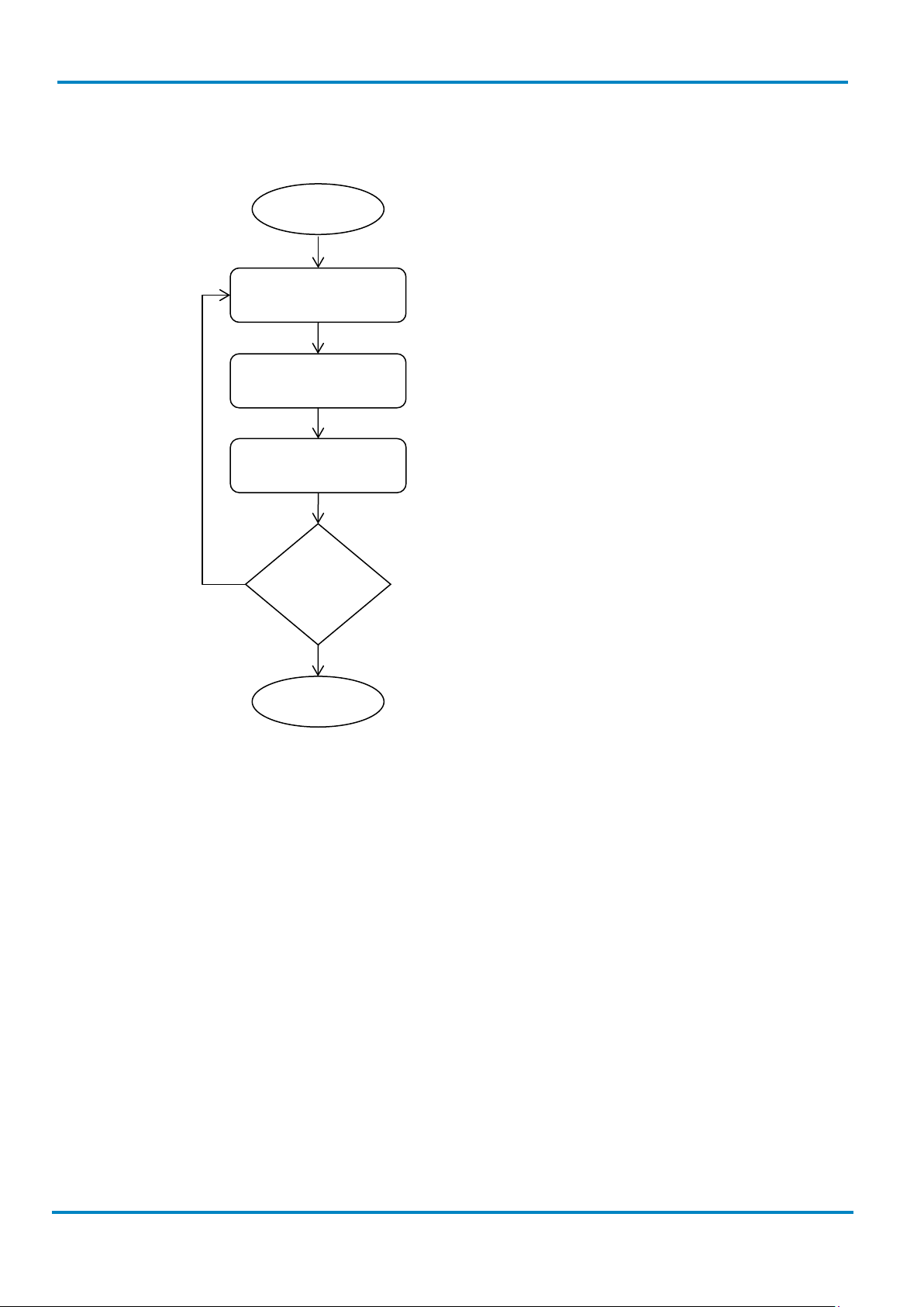
3.2.4 Multiple Scan
Repeat
selection
Select the desired programming
Select one or several option codes for
the desired parameters.
If it‘s necessary scan „FIN“ to
Do you want to select another
Page 30
Programming Procedures
Operating Instructions
& IDM Bluetooth
30
© SICK AG · Germany · All rights reserved · Subject to change without notice
8017159/142O/2019-05-23
Scan one of family
codes
Scan
„PROGRAM“
Scan one or several
option codes
Scan
„END“
Yes
No
Enter Programming mode.
family.
“Multiple” scan selection.
programming family?
Exit programming mode.
Finish cycling selection. (If necessary)
3.2.5 Cycling Scan
Scan “FIN”
Repeat
selection
IDM corded
Select the desired programming
Select one or several option codes for
the desired parameters as “Single” or
Do you want to select another
Page 31

Operating Instructions
Programming Procedures
IDM corded
8017159/142O/2019-05-23
© SICK AG · Germany · All rights reserved · Subject to change without notice
31
codes
Scan
„PROGRAM“
option codes
Scan
„END“
Yes
No
Enter Programming mode.
family.
selection.
programming family?
Exit programming mode.
several option codes
& IDM Bluetooth
3.2.6 Dual Level Scan
Scan one of family
(1st) Scan several
(2nd) Scan one or
Repeat
selection
Select the desired programming
Select several option codes for the
desired parameters.
1. Select one or several option
codes for the desired
parameters.
2. If it’s necessary scan “FIN” to
terminate the option code
Do you want to select another
Page 32

Host Interface Selection
Operating Instructions
& IDM Bluetooth
32
© SICK AG · Germany · All rights reserved · Subject to change without notice
8017159/142O/2019-05-23
PROGRAM
F_DEFAULT
3.3 Host Interface Selection
IDM corded
Family Code Selection P.C. Parameter Selection Option Code
Host Interface Selection
MS IBM PS/2 25-30 series keyboard wedge interface 02
MS Standard/TTL RS-232 peer-to-peer serial 06
MS Wand Emulation 08
MS USB Com Port Emulation 09
MS PS/2 (DOS/V) direct link (keyboard replacement) 10
MS PS/2 (DOS/V) keyboard wedge turbo mode 13
MS PS/2 (DOS/V) keyboard wedge standard mode 14
MS Laser emulation 17
MS USB HID standard mode 18
MS USB HID turbo mode 19
MS USB HID Legacy 20
IDM2xx series doesn’t support Wand emulation, Laser emulation and USB HID Legacy
Page 33

Operating Instructions
Keyboard Interface Control
IDM corded
8017159/142O/2019-05-23
© SICK AG · Germany · All rights reserved · Subject to change without notice
33
PROGRAM
F_DEFAULT
& IDM Bluetooth
3.4 Keyboard Interface Control
3.4.1 Keyboard Layout (Language)
Family Code Selection P.C. Parameter Selection Option Code
Keyboard Layout
SS USA (QWERTY) 00
SS France (AZERTY) 01
SS Germany (QWERTZ) 02
SS United Kingdom (QWERTY) 03
SS Canadian French (QWERTY) 04
SS Spain (Spanish, QWERTY) 05
SS Sweden/Finland (QWERTY) 06
SS Portugal (QWERTY) 07
SS Norway (QWERTY) 08
SS Spain (Latin America, QWERTY) 09
SS Italy (QWERTY) 10
SS Netherlands (QWERTY) 11
SS Denmark (QWERTY) 12
SS Belgium (AZERTY) 13
SS Switzerland-Germany (QWERTZ) 14
SS Iceland (QWERTY) 15
SS Japan (DOS/V) 16
SS Czech (QWERTY) 17
Please refer to the ASCII/HEX Table listed in the Appendix to determine the HEX codes for characters,
symbols, and functions to be used as preamble or postamble.
To set preamble or postamble as function key output, you must enable the “Function Key Emulation” feature
first.
Keyboard Interface Message String:
Preamble Data Length Prefix Symbol ID Scanned Data Suffix Symbol ID Postamble Record Suffix
1-15
characters
2-4 digits 1 or 3 characters Variable
length
1 or 3 characters 1-15
characters
1 character
Page 34

Keyboard Interface Control
Operating Instructions
& IDM Bluetooth
34
© SICK AG · Germany · All rights reserved · Subject to change without notice
8017159/142O/2019-05-23
PROGRAM
F_DEFAULT
FNC1 Symbol Char.
Caps Lock Release
3.4.2 Suffix, Preamble, Postamble, FNC1 Transmit, Caps Lock
IDM corded
Family Code Selection P.C. Parameter Selection Option Code
Record Suffix
Preamble
Postamble
SS None 0
SS RETURN 1
SS TAB 2
SS SPACE 3
SS ENTER (Numeric Key Pad) 4
SS User defined character (1 character) 5, (00-7F)
SS None FIN
MS 1-15 characters [00-7F], FIN
Maximum 15-character input.
Scan “FIN” to terminate this selection.
SS None FIN
MS 1-15 characters [00-7F], FIN
Transmit
Caps Lock Control
Control
Maximum 15-character input.
Scan “FIN” to terminate this selection.
SS Disable 0
SS Enable
SS “Caps Lock Off” State 0
SS “Caps Lock On” State 1
SS Auto Detect (PC/AT, PS/2, Keyboard Replacement
and DOS/V Machines only)
SS “Caps Lock On, Caps Off” 0
SS “Caps Lock On, Shift Off”
1
2
1
FNC1 Symbol Character. Transmit
When this function is enabled and the FNC1 is contained in the scanned data, the scanner transmits the
FNC1 to the host. When the scanner interface is set to keyboard, the scanned code is converted to
corresponding key function before it is transmitted.
The function of “Caps Lock Control” and “Key Pad Emulation” are only available for IBM PC/AT, PS/VP, PS/2
series personal computers and compatible machines. While selecting the other host interfaces, these
selections don’t perform the above functions.
Page 35

Operating Instructions
Keyboard Interface Control
IDM corded
8017159/142O/2019-05-23
© SICK AG · Germany · All rights reserved · Subject to change without notice
35
PROGRAM
F_DEFAULT
& IDM Bluetooth
Please check the actual Caps Lock state in use while software application is running. If the Caps Lock state is
off, select “Caps Lock Off” state, and then the Hand-held scanner will perform normal data transmission. If
the Caps Lock state is on, select “Caps Lock On” state. If “Auto Detect” is selected, the Hand-held scanner will
perform special transmission handshaking without changing the status of Caps Lock switch.
3.4.3 Delay Settings
Family Code Selection P.C. Parameter Selection Option Code
Intermessage Delay
Intercharacter Delay
Interfunction Delay
SS None FIN
MS 01-99 (x5) msec. (2 digits)
Scan 2 digits from the option code chart in the Appendix;
then the scanner will terminate this selection automatically.
SS None FIN
MS 01-99 (x5) msec. (2 digits)
Scan 2 digits from the option code chart in the Appendix;
then the scanner will terminate this selection automatically.
SS None FIN
MS 01-99 (x5) msec. (2 digits)
Scan 2 digits from the option code chart in the Appendix;
then the scanner will terminate this selection automatically.
Intermessage Delay: is a time delay between messages outputted by the Hand-held scanner. Increasing this
delay will help host applications to process the incoming data on time.
Intercharacter Delay: is a time delay between data characters outputted by the Hand-held scanner. These two
parameters are used to synchronize data communication when: 1) the data transmission speed is too fast,
characters may be skipped; 2) multitasking operation system or host computers in a network may slow down
the keyboard handling; 3) various notebook or desktop PC systems require different timing parameter
settings. It is recommended to always add one extra unit as safety margin when adjusting these two
parameters.
Interfunction Delay: is a time delay of between transmission and reception of each segment of the message
string.
Intermessage, Intercharacter and Interfunction Delay are not available for IDM Bluetooth scanners
working in SPP or HID mode.
Page 36

Keyboard Interface Control
Operating Instructions
& IDM Bluetooth
36
© SICK AG · Germany · All rights reserved · Subject to change without notice
8017159/142O/2019-05-23
PROGRAM
F_DEFAULT
3.4.4 Function Key, Key Pad Emulation, Upper/Lower Case, Dollar Sign
IDM corded
Family Code Selection P.C. Parameter Selection Option Code
Function Key Emulation
SS Enable ASCII 00-31 code as keyboard function code
0
output
SS Ctrl-Output 1
Refer to Appendix – Keyboard Function Code Table for details.
Key Pad Emulation
SS Disable key pad emulation 0
SS Enable numeric output as key pad (Num Lock On)
1
output
Upper/ Lower Case
SS Normal case (neglect the upper/lower case control) 0
SS Inverse case (change all characters output to inverse
1
case)
SS Upper case (force all characters output as upper case) 2
SS Lower case (force all characters output as lower case) 3
Dollar Sign Control
SS Dollar sign output as “$“ 0
SS
Dollar sign output as “¥“
SS Dollar sign output as “€“ 2
SS Dollar sign output as “£“ 3
SS Dollar sign output as “¢“ 4
3.4.5 Barcode Encoding Format, Keyboard Output
Family Code Selection P.C. Parameter Selection Option Code
Barcode Encoding
Format
MS UTF8 00
MS Code page 950 10
MS Code page 949 11
MS Code page 936 12
MS Code page 932 13
MS Code page 874 14
MS WIN1250 15
MS WIN1251 16
1
MS
WIN1252 ◆
MS WIN1253 18
MS WIN1254 19
MS WIN1255 1a
17
Page 37

Operating Instructions
Keyboard Interface Control
IDM corded
8017159/142O/2019-05-23
© SICK AG · Germany · All rights reserved · Subject to change without notice
37
& IDM Bluetooth
Family Code Selection P.C. Parameter Selection Option Code
MS WIN1256 1b
MS WIN1257 1c
MS WIN1258 1d
MS ISO 8859-1 Latin 1, Western European 1e
MS ISO 8859-2 Latin 2, Central European 1f
MS ISO 8859-3 Latin 3, Southern European 20
MS ISO 8859-4 Latin 4, Northern European 21
MS ISO 8859-5 Cyrillic 22
MS ISO 8859-6 Arabic 23
MS ISO 8859-7 Greek 24
MS ISO 8859-8 Hebrew 25
MS ISO 8859-9 Latin 5, Turkish 26
MS ISO 8859-10 Latin 6, Nordic 27
Keyboard Output
MS ISO 8859-11 Thai 28
MS ISO 8859-13 Latin 7, Baltic 29
MS ISO 8859-14 Latin 8, Celtic 2a
MS ISO 8859-15 Latin 9 2b
MS ISO 8859-16 Latin 10, South-Eastern European 2c
MS MAC Unicode Output 01
MS WIN Notepad Unicode Output 02
MS WIN Wordpad Unicode 03
MS Output Code page 950 Output 10
MS Code page 949 Output 11
MS Code page 936 Output 12
MS Code page 932 Output 13
MS Code page 874 Output 14
MS WIN1250 Output 15
MS WIN1251 Output 16
MS
WIN1252 Output ◆
17
MS WIN1253 Output 18
MS WIN1254 Output 19
MS Code page 852 Output 30
MS Code page 855 Output 31
MS Code page 866 Output 32
MS Code page 850 Output 33
MS Code page 437 Output 34
MS Code page 737 Output 35
MS Code page 857 Output 36
Page 38

Keyboard Interface Control
Operating Instructions
& IDM Bluetooth
38
© SICK AG · Germany · All rights reserved · Subject to change without notice
8017159/142O/2019-05-23
IDM corded
Family Code Selection P.C. Parameter Selection Option Code
MS Code page 862 Output 37
MS Code page 720 Output 38
MS Code page 775 Output 39
MS WIN1255 Output 1a
MS WIN1256 Output 1b
MS WIN1257 Output 1c
MS WIN1258 Output 1d
Corresponding Languages: Please see Appendix below, “Code Page - Table of Corresponding Languages”.
Barcode Encoding Format: 2D barcodes can be encoded using different code pages. To properly decode the
data of a 2D barcode, the scanner must first be set to the corresponding code page of such data. Select UTF8
if the 2D barcode was encoded in Unicode (UTF-8)
Keyboard Output: Different languages use different code pages. For your scanner to properly display the
content of a2D barcode, select the code page that corresponds to the content’s language. Please check your
system locale setting in Windows and make sure that it also matches this language.
1) Mac Device Output: If your host is a Mac device, select “MAC Unicode Output” as the scanner’s output
setting (the data will be in Unicode). You must also first ensure that your Mac device has the required
Unicode Hex Input Setup and is configured for the 16-bit input method. Please see Appendix below, “Code
Page - Unicode Hex Input Setup”.
2) WIN Notepad Unicode Output: If your host is a Windows device, you can output the data in Unicode format
to Notepad. You must first ensure that your Windows device has the required Unicode Hex Input Setup,
and is set to the US English input method. Please see Appendix below, “Code Page - Unicode Hex Input
Setup”.
3) WIN WordPad Unicode Output: If your host is a Windows device, you can output the data in Unicode
format to WordPad. You must first ensure that your Windows device is set to the US English input method.
Page 39

Operating Instructions
Serial Interface Control
IDM corded
8017159/142O/2019-05-23
© SICK AG · Germany · All rights reserved · Subject to change without notice
39
PROGRAM
F_DEFAULT
Data
Length
Prefix
Symbol ID
Scanned
Data
Suffix
Symbol ID
Record
Suffix
& IDM Bluetooth
3.5 Serial Interface Control
3.5.1 Suffix, Preamble, Postamble
Family Code Selection P.C. Parameter Selection Option Code
STX/ ETX Control
Record Suffix
Preamble
SS Disable STX/ETX transmission 0
SS Enable STX/ETX transmission 1
STX/ETX are two characters used to indicate the starting and
ending of the total data frame transmitted via serial
interface.
SS None 0
SS CR (0DH) 1
SS LF (0AH) 2
SS CRLF (0D0AH) 3
SS TAB (09H) 4
SS SPACE (20H) 5
SS None FIN
MS 1-15 characters [00-7F], FIN
Maximum 15-character input; scan “FIN” to terminate this
selection.
Postamble
FNC1 Symbol Char.
Transmit
SS None FIN
MS 1-15 characters [00-7F], FIN
Maximum 15-character input; scan “FIN” to terminate this
selection.
SS Disable 0
SS Enable 1
When this function is enabled and the FNC1 is contained in
scanned data, the scanner transmits the FNC1 to the host. A
chart of the FNC1 is provided in the GS1-128 ASCII Table.
When the scanner interface is set to keyboard, the scanned
code is converted to corresponding key function before it is
transmitted.
Serial Interface Message String (RS-232, USB COM)
STX Preamble
1
character
1-15
characters
2-4
digits
1 or 3
characters
Variable
length
1 or 3
characters
Postamble ETX
1-15
characters 1 character 1 character
Page 40

Serial Interface Control
Operating Instructions
& IDM Bluetooth
40
© SICK AG · Germany · All rights reserved · Subject to change without notice
8017159/142O/2019-05-23
PROGRAM
F_DEFAULT
3.5.2 Delay Settings
IDM corded
Family Code Selection P.C. Parameter Selection Option Code
Intermessage Delay
Intercharacter Delay
Interfunction Delay
SS None FIN
MS 01-99 (x5) msec. (2 digits)
Scan 2 digits from the option code chart in the Appendix;
then the scanner will terminate this selection automatically.
SS None FIN
MS 01-99 (x5) msec. (2 digits)
Scan 2 digits from the option code chart in the Appendix;
then the scanner will terminate this selection automatically.
SS None FIN
MS 01-99 (x5) msec. (2 digits)
Scan 2 digits from the option code chart in the Appendix;
then the scanner will terminate this selection automatically.
Intermessage Delay: is a time delay between messages outputted by the Hand-held scanner. Increasing this
delay will help host applications to process the incoming data on time.
Intercharacter Delay: is a time delay between data characters outputted by the Hand-held scanner. These two
parameters are used to synchronize data communication when: 1) the data transmission speed is too fast,
characters may be skipped; 2) multitasking operation system or host computers in a network may slow down
the keyboard handling; 3) various notebook or desktop PC systems require different timing parameter
settings. It is recommended to always add one extra unit as safety margin when adjusting these two
parameters.
Interfunction Delay: is a time delay of between transmission and reception of each segment of the message
string.
Intermessage, Intercharacter and Interfunction Delay are not available for IDM Bluetooth scanners
working in SPP or HID mode.
Page 41

Operating Instructions
Serial Interface Control
IDM corded
8017159/142O/2019-05-23
© SICK AG · Germany · All rights reserved · Subject to change without notice
41
PROGRAM
F_DEFAULT
& IDM Bluetooth
3.5.3 Handshaking Protocol, ACK/ NAK
Family Code Selection P.C. Parameter Selection Option Code
Handshaking Protocol
NAK Retry Count
ACK Indication
SS None (free running mode) 0
SS RTS/CTS (hardware handshaking) 1
SS ACK/NAK (software handshaking) 2
SS Xon/Xoff (software handshaking) 3
SS 3 times FIN
SS 000-255 times
SS Disable ACK Time-out Indication 0
SS Enable ACK Time-out Indication 1
SS Disable ACK Indication 2
SS Enable ACK Indication 3
(3 digits)
• USB COM doesn’t support RTS/CTS handshaking protocol.
• When the RTS/CTS Hardware Handshaking option is selected, the RTS (request to send) and CTS
(clear to send) signals will be issued before normal data communication. This option is very helpful to
ensure the reliability of data communication.
• When the ACK/NAK Software Handshaking option is selected, the Hand-held scanner waits for an
ACK (acknowledge) or NAK (not acknowledge) from the host computer after each data transmission. If
the NAK is received, the Hand-held scanner will re-send the data until receiving ACK. (This function is
not available for IDM Bluetooth Scanners in PICO or HID Mode.)
NAK Retry Count
After transmitting data, the scanner expects a NAK response from the host up to the preset “Serial Response
Time-out”. If the scanner doesn’t get a response, the scanner will issue an error indication and discard the
data. When a NAK is received, the scanner transmits the same data again and waits for either an ACK or NAK.
The scanner issues an error indication and discards the data under following two conditions:
1. After preset NAK retry counts is received within the preset serial response time-out.
2. If the preset time-out is up but the preset NAK retry counts haven’t come to the end.
The default retry counts are three times. If you program “0 times”, the scanner will not resend the data to the
host when the scanner receives a NAK. The scanner will discard the data. If you program “255 times”, the
scanner can receive unlimited NAKs from the host within the pre-set serial response time-out.
This function is not available for batch mode. When you enable this function in on-line mode, the out-of-range
function will be disabled automatically.
Page 42

Serial Interface Control
Operating Instructions
& IDM Bluetooth
42
© SICK AG · Germany · All rights reserved · Subject to change without notice
8017159/142O/2019-05-23
PROGRAM
F_DEFAULT
ACK Indication
Disable: There’s neither LED nor beeping indication for this setting.
Enable: There’s a specific LED and beeping indication for this setting.
3.5.4 Response Time-out, Baud Rate
IDM corded
Family Code Selection P.C. Parameter Selection Option Code
Serial Response Time-out
SS None 0
SS 200 mseconds 1
SS 500 mseconds 2
SS 800 mseconds 3
SS 1 second 4
SS 2 seconds 5
SS 3 seconds 6
SS 4 seconds 7
SS 5 seconds 8
SS 8 seconds 9
SS 10 seconds A
SS 15 seconds B
Baud Rate (BPS)
SS 38.4K BPS 0
SS 19.2K BPS 1
SS 9600 BPS 2
SS 4800 BPS 3
SS 2400 BPS 4
SS 1200 BPS 5
SS 57.6K BPS 8
SS 115.2K BPS 9
The Serial Response Time-out is a pre-defined delay time for the Hand-held scanner to wait for handshaking,
acknowledgment or non-acknowledgment from the host computer
Page 43

Operating Instructions
Serial Interface Control
IDM corded
8017159/142O/2019-05-23
© SICK AG · Germany · All rights reserved · Subject to change without notice
43
PROGRAM
F_DEFAULT
& IDM Bluetooth
3.5.5 Data Frame
Family Code Selection P.C. Parameter Selection Option Code
Data Frame
SS 8, None, 1 0
SS 8, Odd, 1 1
SS 8, Even, 1 2
SS 8, None, 2 5
SS 7, Odd, 1 6
SS 7, Even, 1 7
SS 7, Space, 1 8
SS 7, Mark, 1 9
SS 7, None, 2 A
SS 7, Odd, 2 B
SS 7, Even, 2 C
SS 7, Space, 2 D
SS 7, Mark, 2 E
Page 44

Wand/ Laser Emulation Control (IDM1xx series)
Operating Instructions
& IDM Bluetooth
44
© SICK AG · Germany · All rights reserved · Subject to change without notice
8017159/142O/2019-05-23
PROGRAM
F_DEFAULT
3.6 Wand/ Laser Emulation Control (IDM1xx series)
3.6.1 Output Polarity, Signal State, Margin/ Module Time
IDM corded
Family Code Selection P.C. Parameter Selection Option Code
Output Polarity
Initial Signal State
Margin Time
SS High level (5Vdc) on Bar (low level on Space) 0
SS Low level (0Vdc) on Bar (high level on Space) 1
Determine the output voltage level for both bar and space.
SS High Level (5Vdc) 0
SS Low Level (0Vdc) 1
Determine the initial state of output voltage level.
SS 10 msec. 0
SS 15 msec. 1
SS 20 msec. 2
SS 25 msec. 3
SS 30 msec. 4
Module Time
Narrow/ Wide ratio
Code 39/ Code 128
Emulation
SS Extremely short 0
SS Short 1
SS Medium 2
SS Long 3
SS 1:2 0
SS 1:2.5 1
SS 1:3 2
SS Disable standard Code 39 emulation 0
SS Enable standard Code 39 skip emulation 1
SS Enable standard Code 39 replace emulation 2
SS Enable Full ASCII Code 39 emulation 3
SS Enable Code 128 emulation 4
Code 39 Skip
When this option is selected, all scanned data will be translated as Standard Code 39 wand/laser emulation
output. If any lower case characters are read, they will be translated to upper case characters. Any other
characters that are not available in Code 39 symbology set will be skipped.
Code 39 Replace
Any character not normally available in the standard Code 39 symbology set will be translated as Space.
Page 45

Operating Instructions
Symbology Reading Control
IDM corded
8017159/142O/2019-05-23
© SICK AG · Germany · All rights reserved · Subject to change without notice
45
PROGRAM
F_DEFAULT
& IDM Bluetooth
3.7 Symbology Reading Control
3.7.1 User Defined Symbol ID
Family Code Selection P.C. Parameter Selection 1st Option Code 2nd Option Code
Symbol ID 1 character
DS Code 128 (default=B) 00 (1 character)
GS1-128 (default=C) 01 (1 character)
UPC-A (default=A) 02 (1 character)
EAN-13 (default=F) 03 (1 character)
Codabar/NW-7 (default=D) 04 (1 character)
Code 39/Code 32 (default=G) 05 (1 character)
Code 93 (default=H) 06 (1 character)
Standard/Industrial 2 of 5 (default=I) 07 (1 character)
Interleaved 2 of 5 (default=J) 08 (1 character)
Matrix 2 of 5 (default=K) 09 (1 character)
China Postal Code (default=L) 10 (1 character)
German Postal Code (default=M) 11 (1 character)
IATA (default=O) 12 (1 character)
Code 11 (default=P) 13 (1 character)
MSI/Plessey (default=R) 14 (1 character)
UK/Plessey (default=S) 15 (1 character)
Telepen (default=T) 16 (1 character)
GS1 DataBar (default=X) 17 (1 character)
UPC-E (default=E) 18 (1 character)
EAN-8 (default=N) 19 (1 character)
Trioptic Code 39 (default=W) 20 (1 character)
UCC Coupon Extended Code
21 (1 character)
(default=Z)
PDF417/Micro PDF417 (default=V) 22 (1 character)
Codablock F (default=Y) 23 (1 character)
Code 16K (default=Q) 24 (1 character)
Code 49 (default=U) 25 (1 character)
Korea Post Code (default=a) 26 (1 character)
Page 46

Symbology Reading Control
Operating Instructions
& IDM Bluetooth
46
© SICK AG · Germany · All rights reserved · Subject to change without notice
8017159/142O/2019-05-23
PROGRAM
F_DEFAULT
PROGRAM
F_DEFAULT
IDM corded
Family Code Selection P.C. Parameter Selection Option Code 2nd Option Code
Symbol ID 1 character
DS QR & Micro QR Code (default=b) 28 (1 character)
Data Matrix (default=c) 29 (1 character)
Australian Post (default=g) 33 (1 character)
British Post (default=h) 34 (1 character)
Intelligent Mail (USPS 4CB/One Code)
(default=j)
Japan Post (default=k) 37 (1 character)
Netherlands KIX Post (default=l) 38 (1 character)
US Planet (default=m) 39 (1 character)
US Postnet (default=o) 41 (1 character)
3.7.2 Symbology ID Transmission
36 (1 character)
Family Code Selection P.C. Parameter Selection Option Code
Symbology ID
Transmission
SS Disable symbology ID transmission 0
SS Enable prefix SICK symbology ID transmission 1
SS Enable suffix SICK symbology ID transmission 2
SS Enable both prefix and suffix SICK symbology ID
transmission
SS Enable prefix AIM symbology ID transmission 4
SS Enable suffix AIM symbology ID transmission 5
SS Enable both prefix and suffix AIM symbology ID
transmission
3
6
Page 47

Operating Instructions
Symbology Reading Control
IDM corded
8017159/142O/2019-05-23
© SICK AG · Germany · All rights reserved · Subject to change without notice
47
PROGRAM
F_DEFAULT
Remember to scan
& IDM Bluetooth
3.7.3 Readable Bar Codes
If your application is known, you may select those known symbologies only to increase the reading speed and
decrease the possibility of reading error. Furthermore, adding the “Symbology ID” into the transmitted data is
also helpful to identify the specific symbology.
Family Code Selection P.C. Parameter Selection Option Code
Readable Symbology
“FIN“ after you
terminate this section
(Cycling Scan).
If you choose “Auto”
(Single Scan) you
don’t need to scan
“FIN”.
SS Auto 00
CS Popular 1D CO
CS Code 128 * 01
CS GS1-128 31
CS UPC-A 02
CS UPC-E * 03
CS EAN-13 * 04
CS EAN-8 * 05
CS Codabar/NW-7 * 06
CS Code 39 * 07
CS Trioptic Code 39 47
CS Standard/Industrial 2 of 5 08
CS Matrix 2 of 5 38
CS Interleaved 2 of 5 * 48
CS China Postal Code 58
CS Germany Postal Code 68
CS Code 93 * 09
CS Code 11 10
CS MSI/Plessey 11
CS UK/Plessey 12
CS Telepen 13
CS GS1 DataBar (RSS-14) * 14
CS IATA 15
CS Coupon Code 16
CS PDF417 * /Micro PDF417 17
CS Codablock F 18
CS Code 16K 19
CS Code 49 20
CS Korea Post Code 21
Page 48

Symbology Reading Control
Operating Instructions
& IDM Bluetooth
48
© SICK AG · Germany · All rights reserved · Subject to change without notice
8017159/142O/2019-05-23
PROGRAM
F_DEFAULT
IDM corded
Family Code Selection P.C. Parameter Selection Option Code
Readable Symbology
CS QR Code */ Micro QR Code * A0
CS Data Matrix * A1
CS Maxi Code A2
CS Aztec Code * A3
CS Chinese Sesible (Han Xin) code A4
CS Australian Post B0
CS British Post B1
CS Intelligent Mail barcode B3
CS Japanese Post B4
CS KIX Post B5
CS Planet Code B6
CS Postnet B8
Above symbologies marked with * are enabled as default. When you select “Auto”, the scanner only reads
those symbologies marked with *.
8", "Codabar/NW-7", "Code 39", " Interleaved 2 of 5", "Code 93", "GS1 DataBar
"Popular 1D" includes "Code 128", "GSA-128", "UPC-A", "UPC-E", "EAN-13", "EAN-
(RSS-14)".
When you set the minimum and maximum length of each symbology, please note the data length of the
scanned bar code doesn’t include start/stop characters.
Page 49

Operating Instructions
Symbology Reading Control
IDM corded
8017159/142O/2019-05-23
© SICK AG · Germany · All rights reserved · Subject to change without notice
49
PROGRAM
F_DEFAULT
& IDM Bluetooth
3.7.4 Code 39/ Code 32
Family Code Selection P.C. Parameter Selection Option Code
Code 39 Family Setting
SS Disable Code 39 0
SS Enable Code 39 1
SS Select Standard Code 39 as primary format 2
SS Select Full ASCII Code 39 as primary format 3
SS Select Code 32 (PARAF, Italian Pharmaceutical) as
4
primary format
SS Disable start/stop symbol transmission 5
SS Enable start/stop symbol transmission 6
SS Disable Code 32 leading A transmission 7
SS Enable Code 32 leading A transmission 8
SS Disable MOD 43 check digit verification 9
SS Enable MOD 43 check digit verification A
Trioptic Code 39 Setting
Code 39 Min. Length
Code 39 Max. Length
Trioptic Code 39 and Code 39 Full ASCII cannot be enabled simultaneously.
SS Disable check digit transmission B
SS Enable check digit transmission C
SS Disable Code 39 buffering D
SS Enable Code 39 buffering E
SS Disable Trioptic Code 39 0
SS Enable Trioptic Code 39
1
SS Default (01) FIN
MS 01-98 (2 digits)
Scan 2 digits from the option code chart in the Appendix;
then the scanner will terminate this selection automatically.
SS Default (98) FIN
MS 01-98 (2 digits)
Scan 2 digits from the option code chart in the Appendix;
then the scanner will terminate this selection automatically.
Page 50

Symbology Reading Control
Operating Instructions
& IDM Bluetooth
50
© SICK AG · Germany · All rights reserved · Subject to change without notice
8017159/142O/2019-05-23
PROGRAM
F_DEFAULT
3.7.5 Code 39
IDM corded
Family Code Selection P.C. Parameter Selection Option Code
Code 39 Security Level
SS Level 0 0
SS Level 1 1
SS Level 2 2
SS Level 3 3
Code 39 Security Level
The scanner offers four levels of decode security for Code 39 bar codes:
• Level 0: If you are experiencing misread of poorly-printed or serious out-of-spec. bar codes in level 1
please select level 0.
• Level 1: If you are experiencing misread of poorly-printed or out-of-spec. bar codes in level 2, please
select level 1.
• Level 2: This is the default setting which allows the scanner to operate fastest, while providing
sufficient security in decoding “in-spec” Code 39 bar codes.
• Level 3: If you failed to read poorly-printed or out-of-spec. bar codes in level 2, please select level 3.
This is the most aggressive setting and may increase the misread.
Page 51

Operating Instructions
Symbology Reading Control
IDM corded
8017159/142O/2019-05-23
© SICK AG · Germany · All rights reserved · Subject to change without notice
51
PROGRAM
F_DEFAULT
& IDM Bluetooth
3.7.6 Codabar/ NW-7
Family Code Selection P.C. Parameter Selection Option Code
Codabar Settings
SS Disable Codabar 0
SS Enable Codabar 1
SS Select Codabar standard format 2
SS Select Codabar ABC format 3
SS Select Codabar CLSI format 4
SS Select Codabar CX format 5
SS Disable start/stop symbol transmission 6
SS Enable ABCD/ABCD start/stop symbol transmission 7
SS Enable abcd/abcd start/stop symbol transmission 8
SS Enable ABCD/TN*E start/stop symbol transmission 9
SS Enable abcd/tn*e start/stop symbol transmission A
Codabar Check Digit
Settings
Codabar Min. Length
Codabar Max. Length
SS Disable check digit verification B
SS Enable check digit verification C
SS Disable check digit transmission D
SS Enable check digit transmission E
SS Modulus 16 0
SS Modulus 10/weight 3 1
SS Modulus 11 2
SS Modulus 10/weight 2 3
SS 7 check DR 4
SS Weight Modulus 11 5
SS Runes (Modulus 10/weight 2) 6
SS Default (04) FIN
MS 01-98 (2 digits)
Scan 2 digits from the option code chart in the Appendix;
then the scanner will terminate this selection automatically.
SS Default (98) FIN
MS 01-98 (2 digits)
Scan 2 digits from the option code chart in the Appendix;
then the scanner will terminate this selection automatically.
Page 52

Symbology Reading Control
Operating Instructions
& IDM Bluetooth
52
© SICK AG · Germany · All rights reserved · Subject to change without notice
8017159/142O/2019-05-23
PROGRAM
F_DEFAULT
3.7.7 UPC-A/ UPC-E
IDM corded
Family Code Selection P.C. Parameter Selection Option Code
UPC-A Family Settings
SS Disable UPC-A 0
SS Enable UPC-A 1
SS Disable UPC-E 2
SS Enable UPC-E 3
SS Disable UPC-E expansion 4
SS Enable UPC-E expansion 5
SS Disable UPC standardization 6
SS Enable UPC standardization 7
SS Disable UPC numeric system 8
SS Enable UPC numeric system 9
SS Disable UPC-A check digit transmission A
SS Enable UPC-A check digit transmission B
SS Disable UPC-E check digit transmission C
SS Enable UPC-E check digit transmission D
SS Disable UPC “leading 1” portion E
SS Enable UPC “leading 1” portion F
When enable UPC-E expansion, the UPC-E decoded data will be converted to UPC-A format and
affected by related settings, such as UPC standardization, UPC numeric system and UPC-A check digit
transmission.
UPC-E & EAN-8 Expansion: Expand the 8-digit UPC-E and 8-digit ENA-8 to 12-digit UPC-A and 13-digit EAN-13.
UPC-A Standardization: Expand the 12-digit UPC-A to 13-digit EAN-13 with 1 zero insertion.
UPC Lead 1 Numeric System: To read UPC leading with the 1 numeric system, you must enable this option.
WPC Selection
(UPC/EAN/CAN)
UPC-A 12 - 1 - 1 + 2 + 5 + 1 0
Basic
Length
Disable
Check
Digit
Disable
Numeric
System
With 2-digit
Addendum
With 5-digit
Addendum
Enable
Standardization
Enable
Expansion
UPC-E 8 - 1 - 1 + 2 + 5 + 1 + 4
EAN-13 13 - 1 NC + 2 + 5 NC 0
EAN-8 8 - 1 NC + 2 + 5 NC + 5
Page 53

Operating Instructions
Symbology Reading Control
IDM corded
8017159/142O/2019-05-23
© SICK AG · Germany · All rights reserved · Subject to change without notice
53
PROGRAM
F_DEFAULT
& IDM Bluetooth
Family Code Selection P.C. Parameter Selection Option Code
UPC Supplement Settings
UPC/ EAN Security Level
Supplement Scan Vorting
SS Select UPC without supplement digits 0
SS Select UPC with only 2 supplement digits 1
SS Select UPC with only 5 supplement digits 2
SS Select UPC with 2/5 supplement digits 3
SS Disable force supplement digits output 4
SS Enable force supplement digits output 5
SS UPC Family Addenda Separator Off 6
SS UPC Family Addenda Separator On 7
SS Level 0 0
SS Level 1 1
SS Level 2 2
Only available for UPC-A & EAN-13
SS None 0
SS Level 1 1
SS Level 2 2
SS Level 3 3
SS Level 4 4
SS Level 5 5
SS Level 6 6
SS Level 7 7
SS Level 8 8
SS Level 9 9
SS Level 10 A
SS Level 11 B
SS Level 12 C
SS Level 13 D
UPC/EAN Security Level
The scanner offers three levels of decode security for UPC/EAN bar codes:
• Level 0: If you are experiencing misread of poorly-printed or out-of-spec. bar codes, especially in
characters 1, 2, 7, and 8 in level 1, please select level 0. Selection of this security level may
significantly impair the decoding ability of the scanner.
• Level 1: This is the default setting which allows the scanner to operate fastest, while providing
sufficient security in decoding “in-spec” UPC/EAN bar codes.
Page 54

Symbology Reading Control
Operating Instructions
& IDM Bluetooth
54
© SICK AG · Germany · All rights reserved · Subject to change without notice
8017159/142O/2019-05-23
IDM corded
• Level 2: If you are experiencing misread of poorly-printed, soiled or damage bar codes in level 1,
please select level 2. This is the most aggressive setting and may increase the misread.
Supplement Scan Voting
The Supplement Scan Voting is the number of times the same UPC/EAN with 2/5 supplement digits has to be
decoded before it is transmitted. It is helpful when decoding a mix of UPC/EAN symbols with and without
supplement digits. This function is effective when you select UPC/EAN with only 2 supplement digits,
UPC/EAN with only 5 supplement digits or UPC/EAN with 2/5 supplement digits. The default value is Level 3.
When you select a higher level, it may impact the reading speed on poorly-printed, low contrast or damaged
barcode labels.
Page 55

Operating Instructions
Symbology Reading Control
IDM corded
& IDM Bluetooth
8017159/142O/2019-05-23
© SICK AG · Germany · All rights reserved · Subject to change without notice
55
PROGRAM
F_DEFAULT
EAN Settings
SS
Disable EAN-13
0
SS
Enable EAN-13
1
SS
Disable EAN-8
2
SS
Enable EAN-8
3
SS
Disable EAN-8 expansion
4
SS
Enable EAN-8 expansion
5
SS
Disable EAN-13 check digit transmission
6
SS
Enable EAN-13 check digit transmission
7
SS
Disable EAN-8 check digit transmission
8
SS
Enable EAN-8 check digit transmission
9
SS
Disable ISBN/ISSN Conversion reading check
A
SS
Enable ISBN/ISSN Conversion reading check
B
SS
Select EAN without supplement digits
0
SS
Select EAN with only 2 supplement digits
1
SS
Select EAN with only 5 supplement digits
2
SS
Select EAN with 2/5 supplement digits
3
SS
Disable force supplement digits output
4
SS
Enable force supplement digits output
5
SS
EAN Addenda Separator Off
6
SS
EAN Addenda Separator On
7
SS
None
0
SS
Level 1
1
SS
Level 2
2
SS
Level 3
3
SS
Level 4
4
SS
Level 5
5
SS
Level 6
6
SS
Level 7
7
SS
Level 8
8
SS
Level 9
9
SS
Level 10
A
SS
Level 11
B
SS
Level 12
C
SS
Level 13
D
3.7.8 EAN Code
Family Code Selection P.C. Parameter Selection Option Code
EAN Supplement Settings
Supplement Scan Vorting
Page 56

Symbology Reading Control
Operating Instructions
& IDM Bluetooth
56
© SICK AG · Germany · All rights reserved · Subject to change without notice
8017159/142O/2019-05-23
IDM corded
Supplement Scan Voting
The Supplement Scan Voting is the number of times the same UPC/EAN with 2/5 supplement digits has to be
decoded before it is transmitted. It is helpful when decoding a mix of UPC/EAN symbols with and without
supplement digits. This function is effective when you select UPC/EAN with only 2 supplement digits,
UPC/EAN with only 5 supplement digits or UPC/EAN with 2/5 supplement digits. The default value is Level 3.
When you select a higher level, it may impact the reading speed on poorly-printed, low contrast or damaged
barcode labels.
PROGRAM F_DEFAULT
Family Code Selection P.C. Parameter Selection Option Code
EAN Supplement Control
UPC/ EAN Security Level
SS Disable all specific prefix supplement digital output 0
SS Enable all specific prefix supplement digital output 1
SS Enable 491 Supplement Digit Output 2
SS Enable 978/979 Supplement Digit Output 3
SS Enable 977 Supplement Digit Output 4
SS Enable 378/379 Supplement Digit Output 5
SS Enable 414/419 Supplement Digit Output 6
SS Enable 434/439 Supplement Digit Output 7
SS Level 0 0
SS Level 1 1
SS Level 2 2
Only available for UPC-A & EAN-13
EAN Supplement Control
If you select EAN with only 2 or 5 or 2/5 supplement digits and enable 491 prefix supplement digit output, the
scanner will transmit EAN with 2, or 5 or 2/5 supplement digits bar codes starting with 491 prefix. The EAN
without supplement digit will not be transmitted.
If you select EAN with only 2 or 5 or 2/5 supplement digits and enable the other except 491 prefix
supplement digit output, the scanner will transmit EAN with 2, or 5, or 2/5 supplement digits bar codes
starting with specific prefix. The EAN without supplement digit will be transmitted.
Page 57

Operating Instructions
Symbology Reading Control
IDM corded
8017159/142O/2019-05-23
© SICK AG · Germany · All rights reserved · Subject to change without notice
57
PROGRAM
F_DEFAULT
& IDM Bluetooth
UPC/EAN Security Level
The scanner offers three levels of decode security for UPC/EAN bar codes:
• Level 0: If you are experiencing misread of poorly-printed or out-of-spec. bar codes, especially in
characters 1, 2, 7, and 8 in level 1, please select level 0. Selection of this security level may
significantly impair the decoding ability of the scanner.
• Level 1: This is the default setting which allows the scanner to operate fastest, while providing
sufficient security in decoding “in-spec” UPC/EAN bar codes.
• Level 2: If you are experiencing misread of poorly-printed, soiled or damage bar codes in level 1,
please select level 2. This is the most aggressive setting and may increase the misread.
3.7.9 UCC Coupon Extended Code
Family Code Selection P.C. Parameter Selection Option Code
UCC Coupon Extended
Code Setting
SS Disable UCC Coupon Extended Code 0
SS Enable UCC Coupon Extended Code
1
UCC Coupon Extended Code
When UCC coupon extended code function is enabled, scanner decodes UPC-A barcodes starting with digit
“5”, EAN-13 barcodes starting with digit “99” and GS1-128 Coupon Codes. UPC-A, EAN-13 and EAN-128 must
be enabled to scan all types of Coupon Codes.
Page 58

Symbology Reading Control
Operating Instructions
& IDM Bluetooth
58
© SICK AG · Germany · All rights reserved · Subject to change without notice
8017159/142O/2019-05-23
PROGRAM
F_DEFAULT
3.7.10 IATA & Interleaved 2 of 5
IDM corded
Family Code Selection P.C. Parameter Selection Option Code
IATA Settings
SS Disable IATA 0
SS Enable IATA 1
SS Select 15-digit fixed length IATA checking 2
SS Select variable length IATA 3
SS Disable check digit verification 4
SS Enable check digit automatic verification 5
SS Enable S/N checking digit verification only 6
SS Enable CPN checking digit verification only 7
SS Enable CPN, Airline and S/N check digit verification 8
SS Disable check digit transmission 9
SS Enable check digit transmission A
SS Disable start/stop symbol transmission B
SS Enable start/stop symbol transmission C
Interleaved 2 of 5
Settings
SS Disable Interleaved 2 of 5 0
SS Enable Interleaved 2 of 5 1
SS Select Interleaved 2 of 5 as primary format 2
SS Select German Postal Code as primary format 3
SS No check character 4
SS Validate USS check digit 5
SS Validate OPCC check digit 6
SS Disable check digit transmission 7
SS Enable check digit transmission 8
Page 59

Operating Instructions
Symbology Reading Control
IDM corded
8017159/142O/2019-05-23
© SICK AG · Germany · All rights reserved · Subject to change without notice
59
PROGRAM
F_DEFAULT
& IDM Bluetooth
3.7.11 Code 25 Family
Family Code Selection P.C. Parameter Selection Option Code
Code 25 Settings
SS Disable Standard/Industrial 2 of 5 0
SS Enable Standard/Industrial 2 of 5 1
SS Disable Matrix 2 of 5 2
SS Enable Matrix 2 of 5 3
SS Disable China Postal Code 4
SS Enable China Postal Code 5
SS Disable check digit verification 6
SS Enable check digit verification 7
SS Disable check digit transmission 8
SS Enable check digit transmission 9
Code 25 Family Min.
Length
SS Default (04) FIN
MS 01-98 (2 digits)
Code 25 Family Max.
For Code25 setting, we recommend you to select only one type of Code 25 or set the
maximum/minimum bar code length. To decode all types of Code 25 or to variable length of Code 25
will increase the possibility of reading error.
Length
Scan 2 digits from the option code chart in the Appendix;
then the scanner will terminate this selection automatically.
SS Default (98) FIN
MS 01-98 (2 digits)
Scan 2 digits from the option code chart in the Appendix;
then the scanner will terminate this selection automatically.
Page 60

Symbology Reading Control
Operating Instructions
& IDM Bluetooth
60
© SICK AG · Germany · All rights reserved · Subject to change without notice
8017159/142O/2019-05-23
PROGRAM
F_DEFAULT
3.7.12 Code 11 & Code 93
IDM corded
Family Code Selection P.C. Parameter Selection Option Code
Code 11 Settings
SS Disable Code 11 0
SS Enable Code 11 1
SS Disable check digit verification 2
SS Select 1-check digit verification 3
SS Select 2-check digit verification 4
SS Disable check digit transmission 5
SS Enable check digit transmission 6
Code 11 Min. Length
SS Default (04) FIN
MS 01-98 (2 digits)
Scan 2 digits from the option code chart in the Appendix;
then the scanner will terminate this selection automatically.
Code 11 Max. Length
SS Default (98) FIN
MS 01-98 (2 digits)
Code 39 Settings
Code 39 Min. Length
Code 39 Max. Length
Scan 2 digits from the option code chart in the Appendix;
then the scanner will terminate this selection automatically.
SS Disable Code 93 0
SS Enable Code 93 1
SS Disable check digit transmission 2
SS Enable check digit transmission 3
SS Default (01) FIN
MS 01-98 (2 digits)
Scan 2 digits from the option code chart in the Appendix;
then the scanner will terminate this selection automatically.
SS Default (98) FIN
MS 01-98 (2 digits)
Scan 2 digits from the option code chart in the Appendix;
then the scanner will terminate this selection automatically.
Page 61

Operating Instructions
Symbology Reading Control
IDM corded
8017159/142O/2019-05-23
© SICK AG · Germany · All rights reserved · Subject to change without notice
61
PROGRAM
F_DEFAULT
& IDM Bluetooth
3.7.13 MSI/ Plessey
Family Code Selection P.C. Parameter Selection Option Code
MSI/ Plessey Settings
SS Disable MSI/Plessey 0
SS Enable MSI/Plessey 1
SS Select MOD 10 check digit 2
SS Select MOD 10-10 check digit 3
SS Select MOD 11-10 check digit 4
SS Disable check digit transmission 5
SS Enable check digit transmission 6
MSI/ Plessey Min. Length
SS Default (04) FIN
MS 01-98 (2 digits)
Scan 2 digits from the option code chart in the Appendix;
then the scanner will terminate this selection automatically.
MSI/ Plessey Max.
Length
SS Default (98) FIN
MS 01-98 (2 digits)
Scan 2 digits from the option code chart in the Appendix;
then the scanner will terminate this selection automatically.
Page 62

Symbology Reading Control
Operating Instructions
& IDM Bluetooth
62
© SICK AG · Germany · All rights reserved · Subject to change without notice
8017159/142O/2019-05-23
PROGRAM
F_DEFAULT
3.7.14 Code 128
IDM corded
Family Code Selection P.C. Parameter Selection Option Code
Code 128 Settings
Code 128 Min. Length
Code 128 Max. Length
SS Disable Code 128 0
SS Enable Code 128 1
SS ISBT Concatenation Off 2
SS ISBT Concatenation On 3
SS ISBT Concatenation on – Check ISBT table 4
SS ISBT Concatenation Auto 5
SS Default (01) FIN
MS 01-98 (2 digits)
Scan 2 digits from the option code chart in the Appendix;
then the scanner will terminate this selection automatically.
SS Default (98) FIN
MS 01-98 (2 digits)
Code 128 Security Level
Scan 2 digits from the option code chart in the Appendix;
then the scanner will terminate this selection automatically.
SS Level 0 0
SS Level 1 1
Code 128 Setting
• ISBT Concatenation Off: The scanner will not output ISBT concatenated barcodes.
• ISBT Concatenation On: The scanner will only decode and output ISBT concatenated barcodes. The
scanner will not decode or output single ISBT barcodes.
• ISBT Concatenation On – Check ISBT table: The scanner will only output ISBT concatenated barcodes
that conform to ICCBBA standards. The scanner will not output single ISBT barcodes or ISBT
concatenated barcodes that do not conform to ICCBBA standards.
• ISBT Concatenation Auto: The Scanner will decode and output both ISBT concatenated barcodes and
single ISBT barcodes
Page 63

Operating Instructions
Symbology Reading Control
IDM corded
8017159/142O/2019-05-23
© SICK AG · Germany · All rights reserved · Subject to change without notice
63
& IDM Bluetooth
Code 128 Security Level
The scanner offers two levels of decode security for Code128 bar codes:
• Level 0: If you are experiencing misread of poor-printed or out-of-spec. bar codes in level 1, please
select level 0.
• Level 1: This is the default setting which allows the scanner to operate fastest, while providing
sufficient security in decoding "in-spec." Code 128 bar codes.
Page 64

Symbology Reading Control
Operating Instructions
& IDM Bluetooth
64
© SICK AG · Germany · All rights reserved · Subject to change without notice
8017159/142O/2019-05-23
PROGRAM
F_DEFAULT
Disable “DD=00” transmission when AI data field contains
the date
Enable “DD=00” transmission when AI data field contains
the date
3.7.15 GS1-128
IDM corded
Family Code Selection P.C. Parameter Selection Option Code
GS1-128 Family Setting
GS1-128 Min. Length
SS
Disable GS1-128 special function
SS
Enable GS1-128 special function
SS
Disable First FNC1 transmission
SS
Enable First FNC1 convert to “]C1” and transmission
SS
Disable Application Identifier output
SS
Enable Application Identifier output
SS
Enable Application Identifier output with additional “()”
1
SS
SS
SS
Disable a dot insert in the decimal point position
SS
Enable a dot inset in the decimal point position
SS Default (01) FIN
0
1
2
3
4
5
6
7
8
9
A
MS 01-Maximum (2 digits)
Scan 2 digits from the option code chart in the Appendix; then the
scanner will terminate this selection automatically.
GS1-128 Max. Length
SS Default (98) FIN
MS 98-Minimum (2 digits)
Scan 2 digits from the option code chart in the Appendix; then the
scanner will terminate this selection automatically.
GS1-128 Edition Mode
SS None FIN
MS 1 – 10 Application Identifier (AIs) and Prefix, Suffix input [AI table]2,[GS1-128
Please scan the AI barcodes and ASCII barcodes in your desired output
sequence.
GS1-128 Edition Mode
Output Control
SS If the application identifier set in edition mode is not found,
only the Header Terminator Separator is output
SS If the application identifier set in edition mode is not found,
the Header Terminator Separator is not output.
If option 1 is chosen, the following settings can be applied:
SS If data was completely un-match, do not output original data 2
SS If data was completely un-match, output original data 3
1
Before using all GS1-128 functions, GS1-128 special function must be enabled via GS1-128 Family Settings.
2
For the Application Identifier (AI) table see chapter 6.6 on page 123
3
For the GS1-128 ASCII table see chapter 6.5 on page 120
ASCII table]
0
1
3
,[FIN]
Page 65

Operating Instructions
Symbology Reading Control
IDM corded
8017159/142O/2019-05-23
© SICK AG · Germany · All rights reserved · Subject to change without notice
65
PROGRAM
F_DEFAULT
application identifier with additional “()”
GS1-128 special function list
& IDM Bluetooth
Family Code Selection P.C. Parameter Selection Option Code
GS1-128 Element String
Separator
GS1-128 Data Separator
GS1-128 FNC1 since the
second transmission setting
GS1-128 Error Output Setting
SS None FIN
SS User defined character (1~2 characters) [GS1-128 ASCII Table]1, [FIN]
SS
None
MS
User defined character (1~2 characters)
[GS1-128 ASCII Table]
FIN
1
, [FIN]
SS None 0
MS GS (1DH) 1
MS User defined character (1~2 characters) 2, [GS1-128 ASCII Table]1, [FIN]
SS When Code 128 is converted into GS1-128,
0
no data output when Code 128 is read
SS Read and data output of Code 128, even
1
when Code 128 is converted to GS1-128
When the decode is not done as GS1-128
GS1 DataBar Output Control
SS
Disable GS1 DataBar (RSS-14) output
SS
Enable GS1 DataBar (RSS-14) output
application identifier with additional “()”
Record Suffix
USB (HID) I/F, AT wedge I/F
SS None 0
SS RETURN 5, [GS1-128 ASCII: 94]1, [FIN]
SS TAB 5, [GS1-128 ASCII: 8C]1, [FIN]
SS SPACE 3
SS User defined character (1 character) 5, [GS1-128 ASCII Table]1, [FIN]
Scanning this barcode shows the GS1-128 special function settings.
1
For the GS1-128 ASCII table see chapter 6.5 on page 120
0
1
Page 66

Symbology Reading Control
Operating Instructions
& IDM Bluetooth
66
© SICK AG · Germany · All rights reserved · Subject to change without notice
8017159/142O/2019-05-23
PROGRAM
F_DEFAULT
3.7.16 UK/ Plessey
IDM corded
Family Code Selection P.C. Parameter Selection Option Code
UK/ Plessey Settings
SS Disable UK/Plessey 0
SS Enable UK/Plessey 1
SS Select UK/Plessey Standard Format 2
SS Select UK/Plessey CLSI Format 3
SS Disable Convert X to A-F 4
SS Enable Convert X to A-F 5
SS Disable check digit transmission 6
SS Enable check digit transmission 7
UK/ Plessey Min. Length
SS Default (04) FIN
MS 01-98 (2 digits)
Scan 2 digits from the option code chart in the Appendix;
then the scanner will terminate this selection automatically.
UK/ Plessey Max. Length
SS Default (98) FIN
MS 01-98 (2 digits)
Scan 2 digits from the option code chart in the Appendix;
then the scanner will terminate this selection automatically.
Page 67

Operating Instructions
Symbology Reading Control
IDM corded
& IDM Bluetooth
8017159/142O/2019-05-23
© SICK AG · Germany · All rights reserved · Subject to change without notice
67
PROGRAM
F_DEFAULT
3.7.17 Telepen
Family Code Selection P.C. Parameter Selection Option Code
Telepen Settings
SS Disable Telepen 0
SS Enable Telepen 1
SS Select Telepen Numeric mode 2
SS Select Telepen Full ASCII mode 3
SS Disable check digit transmission 4
SS Enable check digit transmission 5
Telepen Min. Length
SS Default (04) FIN
MS 01-98 (2 digits)
Scan 2 digits from the option code chart in the Appendix;
then the scanner will terminate this selection automatically.
Telepen Max. Length
SS Default (98) FIN
MS 01-98 (2 digits)
Scan 2 digits from the option code chart in the Appendix;
then the scanner will terminate this selection automatically.
Page 68

Symbology Reading Control
Operating Instructions
& IDM Bluetooth
68
© SICK AG · Germany · All rights reserved · Subject to change without notice
8017159/142O/2019-05-23
PROGRAM
F_DEFAULT
GS1 DataBar Limited
3.7.18 GS1 DataBar
IDM corded
Family Code Selection P.C. Parameter Selection Option Code
GS1 DataBar Settings
Security Level
GS1 DataBar Min. Length
SS Disable GS1 DataBar (RSS-14) 0
SS Enable GS1 DataBar (RSS-14) 1
SS Disable GS1 DataBar Limited 2
SS Enable GS1 DataBar Limited 3
SS Disable GS1 DataBar Expanded 4
SS Enable GS1 DataBar Expanded 5
SS Level 1 0
SS Level 2 1
SS Level 3 2
Only available for GS1 DataBar Limited.
Only available for IDM120 series.
SS Default (04) FIN
MS 01-74 (2 digits)
Only available for Expanded GS1 DataBar.
Scan 2 digits from the option code chart in the Appendix;
then the scanner will terminate this selection automatically.
GS1 DataBar Max.
Length
SS Default (74) FIN
MS 01-74 (2 digits)
Only available for Expanded GS1 DataBar.
Scan 2 digits from the option code chart in the Appendix;
then the scanner will terminate this selection automatically.
GS1 128 Limited Security Level
The scanner IDM120 series offers three levels of decode security for GS1 DataBar Limited bar codes:
• Level 1: If you failed to read poorly-printed or out-of-spec. bar codes in level 2, please select level 1.
This is the most aggressive setting and may increase the misread.
• Level 2: If you are experiencing misread of poor-printed or out-of-spec. bar code in level 3, please
select level 2.
• Level 3: This is the default setting which allows the scanner to operate fastest, while providing
sufficient security in decoding "in-spec." GS1 128 Limited” bar codes.
Page 69

Operating Instructions
Symbology Reading Control
IDM corded
8017159/142O/2019-05-23
© SICK AG · Germany · All rights reserved · Subject to change without notice
69
PROGRAM
F_DEFAULT
& IDM Bluetooth
3.7.19 Composite Codes, Codablock F, PDF417, Micro PDF417
Family Code Selection P.C. Parameter Selection Option Code
Composite Codes
Settings
SS Disable composite codes 0
SS Enable composite codes 1
SS UPC Composite Mode: UPC never linked 2
SS UPC Composite Mode: UPC always linked 3
If “UPC Composite Mode: UPC never linked” is selected, UPC
barcodes are transmitted whether Micro PDF417 symbol is
detected or not.
If “UPC Composite Mode: UPC always linked” is selected,
UPC barcodes are only transmitted when the Micro PDF417
is detected.
Codablock F Settings
SS Disable 0
SS Enable
1
PDF417/ Micro PDF417
Settings
SS Disable PDF417 0
SS Enable PDF417 1
SS Disable MicroPDF417 2
SS Enable MicroPDF417 3
Page 70

Symbology Reading Control
Operating Instructions
& IDM Bluetooth
70
© SICK AG · Germany · All rights reserved · Subject to change without notice
8017159/142O/2019-05-23
PROGRAM
F_DEFAULT
3.7.20 Code 16K & Code 49
IDM corded
Family Code Selection P.C. Parameter Selection Option Code
Code 16K Settings
SS Disable Code 16K 0
SS Enable Code 16K 1
Code 16K Min. Length
SS Default (01) FIN
MS 001-160 (3 digits)
Scan 3 digits from the option code chart in the Appendix;
then the scanner will terminate this selection automatically.
Code 16K Max. Length
SS Default (160) FIN
MS 001-160 (3 digits)
Scan 3 digits from the option code chart in the Appendix;
then the scanner will terminate this selection automatically.
Code 49 Settings
Code 49 Min. Length
Code 49 Max. Length
SS Disable Code 49 0
SS Enable Code 49 1
SS Default (01) FIN
MS 01-81 (2 digits)
Scan 2 digits from the option code chart in the Appendix;
then the scanner will terminate this selection automatically.
SS Default (81) FIN
MS 01-81 (2 digits)
Scan 2 digits from the option code chart in the Appendix;
then the scanner will terminate this selection automatically.
Page 71

Operating Instructions
Symbology Reading Control
IDM corded
& IDM Bluetooth
8017159/142O/2019-05-23
© SICK AG · Germany · All rights reserved · Subject to change without notice
71
PROGRAM
F_DEFAULT
3.7.21 QR Code
Family Code Selection P.C. Parameter Selection Option Code
QR Code Settings
SS Disable QR Code 0
SS Enable QR Code 1
SS Disable MicroQR Code 2
SS Enable MicroQR Code 3
SS Disable QR Code Append 4
SS Enable QR Code Append 5
SS Disable QR Code Inverse Reading 6
SS Enable QR Code Inverse Reading 7
SS Auto detect QR Code Inverse Reading 8
QR Code Min. Length
SS Default (0001) FIN
MS 0001-7089 (4 digits)
QR Code Max. Length
Scan 4 digits from the option code chart in the Appendix;
then the scanner will terminate this selection automatically.
SS Default (7089) FIN
MS 0001-7089 (4 digits)
Scan 4 digits from the option code chart in the Appendix;
then the scanner will terminate this selection automatically.
Page 72

Symbology Reading Control
Operating Instructions
& IDM Bluetooth
72
© SICK AG · Germany · All rights reserved · Subject to change without notice
8017159/142O/2019-05-23
PROGRAM
F_DEFAULT
3.7.22 Data Matrix
IDM corded
Family Code Selection P.C. Parameter Selection Option Code
Data Matrix Settings
Data Matrix Min. Length
SS Disable Data Matrix 0
SS Enable Data Matrix 1
SS Disable Data Matrix Inverse Reading 4
SS Enable Data Matrix Inverse Reading 5
SS Auto Detect Data Matrix Inverse Reading 6
SS Disable Data Matrix Mirror Images 7
SS Enable Data Matrix Mirror Images 8
SS Auto Detect Data Matrix Mirror Images 9
SS Default (0001) FIN
MS 0001-3116 (4 digits)
Scan 4 digits from the option code chart in the Appendix;
then the scanner will terminate this selection automatically.
Data Matrix Max. Length
Small DM Code Reading
SS Default (3116) FIN
MS 0001-3116 (4 digits)
Scan 4 digits from the option code chart in the Appendix;
then the scanner will terminate this selection automatically.
SS Standard 0
SS
Level 1
SS
Level 2
1
2
Small DM Code Reading:
When small DataMatrix code can’t be read by 2D scanner, you can select "Level 1” or “Level 2” to improve the
scanner's ability to read small DataMatrix code. The scanner’s snappiness decreased when you select “Level
1” or “Level 2”. The higher level will take longer time to read the small DataMatrix barcode.
Small DM Code Reading:
Available firmware: IDM24x-3/IDM26x-3 1.00.01 and above
Page 73

Operating Instructions
Symbology Reading Control
IDM corded
8017159/142O/2019-05-23
© SICK AG · Germany · All rights reserved · Subject to change without notice
73
PROGRAM
F_DEFAULT
& IDM Bluetooth
3.7.23 Aztec Code
Family Code Selection P.C. Parameter Selection Option Code
Aztec Code Settings
SS Disable Aztec Code 0
SS Enable Aztec Code 1
Aztec Code Min. Length
SS Default (0001) FIN
MS 0001-3832 (4 digits)
Scan 4 digits from the option code chart in the Appendix;
then the scanner will terminate this selection automatically.
Aztec Code Max. Length
SS Default (3832) FIN
MS 0001-3832 (4 digits)
Scan 4 digits from the option code chart in the Appendix;
then the scanner will terminate this selection automatically.
Page 74

Symbology Reading Control
Operating Instructions
& IDM Bluetooth
74
© SICK AG · Germany · All rights reserved · Subject to change without notice
8017159/142O/2019-05-23
PROGRAM
F_DEFAULT
IDM corded
3.7.24 Autralian Post, US Planet, US Postnet, British Post, Japan Post, Posti 4-State
Family Code Selection P.C. Parameter Selection Option Code
Australian Post Settings
SS Disable Australian Post 0
SS Enable Australian Post 1
SS Raw format Output 2
SS Numeric Encoding Output (N Encoding Table) 3
SS Alphanumeric Encoding Output (C Encoding Table) 4
SS Auto-discriminate Output (Combination C & N
5
Encoding Table)
US Planet Settings
SS Disable US Planet 0
SS Enable US Planet 1
SS Disable Check Digit Transmission 2
SS Enable Check Digit Transmission 3
US Postnet Settings
SS Disable US Postnet 0
SS Enable US Postnet 1
SS Disable Check Digit Transmission 2
SS Enable Check Digit Transmission 3
British Post Settings
SS Disable British Post 0
SS Enable British Post 1
SS Disable Check Digit Transmission 2
SS Enable Check Digit Transmission 3
Japan Post Settings
SS Disable Japan Post 0
SS Enable Japan Post
1
Posti 4-State code
Setting
SS Disable Posti 4-State code Setting 0
SS Enable Posti 4-State code Setting
1
Australian Post Setting
Auto-discriminate output option increases the risk of misread because the encoded data format does not
specify the encoding table used for encoding.
Page 75

Operating Instructions
Symbology Reading Control
IDM corded
8017159/142O/2019-05-23
© SICK AG · Germany · All rights reserved · Subject to change without notice
75
PROGRAM
F_DEFAULT
& IDM Bluetooth
3.7.25 Netherland KIX Code, Intelligent Mail, Korea Post Code
Family Code Selection P.C. Parameter Selection Option Code
Netherlands KIX Code
Settings
SS Disable Netherlands KIX Code 0
SS Enable Netherlands KIX Code 1
Intelligent Mail Settings
(USPS 4CB/ One Code)
SS Disable Intelligent Mail 0
SS Enable Intelligent Mail 1
Korea Post Code Settings
SS Disable Korea Post Code 0
SS Enable Korea Post Code 1
Length fixed in 6 characters.
Page 76

Symbology Reading Control
Operating Instructions
& IDM Bluetooth
76
© SICK AG · Germany · All rights reserved · Subject to change without notice
8017159/142O/2019-05-23
PROGRAM
F_DEFAULT
automatically.
3.7.26 MaxiCode Setting
IDM corded
Family Code Selection P.C. Parameter Selection Option Code
MaxiCode Setting
MaxiCode Min. Length
SS Disable MaxiCode 0
SS Enable MaxiCode 1
SS Default (01) FIN
MS 01-Maximum (3 digits)
Scan 3 digits from the option code chart in
Appendix, then IDM will terminate this selection
automatically.
MaxiCode Max. Length
SS Default (150) FIN
MS 150-Minimum (3 digits)
Scan 3 digits from the option code chart in
Appendix, then IDM will terminate this selection
Page 77

Operating Instructions
Symbology Reading Control
IDM corded
8017159/142O/2019-05-23
© SICK AG · Germany · All rights reserved · Subject to change without notice
77
& IDM Bluetooth
3.7.27 DPM Code
If you own a DPM model (IDMxxx-x2xx) you can enable or disable the DPM code reading functionality by
scanning one of the following barcode commands.
Enable DPM functionality ◆
Disable DPM functionality
In order to verify if the DPM functionality is enabled, please scan the following barcode. If you can read this
barcode, the DPM functionality is enabled.
Test1
IDM Corded scanners: if you scan “factory default” and afterwards disconnect the scanner from your
host device, the DPM functionality will be disabled automatically.
IDM Bluetooth scanners: if you take out the battery the DPM functionality will be disabled
automatically.
If you disable the DPM functionality the performance of reading printed 1D and 2D codes will be
improved.
Page 78

Operation Mode
Operating Instructions
& IDM Bluetooth
78
© SICK AG · Germany · All rights reserved · Subject to change without notice
8017159/142O/2019-05-23
PROGRAM
F_DEFAULT
3.8 Operation Mode
3.8.1 Corded scanners (IDMxx0 series)
IDM corded
Family Code Selection P.C. Parameter Selection
Operation Mode
Option Code
SS Low Power mode (Low power triggering) 0 0
SS Trigger mode (External triggering) 1 1
SS Presentation mode (Auto detection) 2 2
SS Alternative mode (Periodic power off) 3 3
SS Flash mode 4 -
SS Force mode (Continued power on) 5 4
SS Toggle mode (Repeat reading) 6 5
SS Diagnostic mode (Test reading) 7 6
SS Level mode (Auto power off) 8 7
SS Multiple Read Mode - 8
1D scanner
(IDM1x0)
2D scanner
(IDM2x0)
Low Power Mode (Low Power Triggering)
The scanner goes into idle state after scanning the barcode. You must press the trigger to wake up the
scanner for operation. It is very helpful for mobile data collection and applications, which are concerned with
power saving.
Trigger Mode (External Triggering)
The scanner goes into standby state after scanning the barcode. You must press the trigger to turn on the
light source of the scanner before scanning the bar code.
Presentation Mode (Auto Detection)
Presentation mode uses ambient light to detect the barcodes. The light source is off until the scanner detects
an image which is similar to a barcode. Then the light source turns on automatically to read the bar code. If
the light level in the room is not high enough, Presentation Mode may not work properly. You can choose
different level of “Presentation Sensitivity” to meet your application’s requirements. (Please refer to the
setting of “Presentation Sensitivity” on page 86.)
Alternative Mode (Periodic Power Off)
The scanner keeps the light source of the scanner turned on till the pre-defined light source on time is up.
After the scanner turns off the light source, you must press the trigger to turn on the light source again. After
each good read, the timer counter of “Light Source on Time” is reset. For you do not have to press the trigger
frequently it is very convenient for multiple scanning.
Page 79

Operating Instructions
Operation Mode
IDM corded
8017159/142O/2019-05-23
© SICK AG · Germany · All rights reserved · Subject to change without notice
79
PROGRAM
F_DEFAULT
& IDM Bluetooth
Flash Mode (Pulse Driven Reading)
The scanner flashes the light source of the scanner without using the trigger. If the scanner detects an image
which is similar to a barcode, the scanner forces on the light source automatically and scans the barcode.
Flash Duty Cycle adjustment can change the frequency of the blinking.
Force Mode (Continued Power On)
The light source of the scanner is forced on for continued operation without pressing the trigger button. This
mode is convenient for high speed bar code reading.
Toggle Mode (Repeat Reading)
The toggle mode is very similar to the Alternative Mode but without the pre-defined light source on time
concern. You must press the trigger to turn on the light source of the scanner to scan. The scanner keeps the
light source turned on until you press the trigger again.
Diagnostic Mode (Test Reading)
This operation mode is specifically designed for diagnostic purposes. When this operation mode is selected,
the light source of the scanner is force on without regard for other programmable parameters, such as reread
delay, redundancy, and so forth.
Level Mode (Auto Power Off)
When this operation mode is selected, the scanner continues to turn on the light source of the scanner before
a good read or pre-defined “Light Source on Time”. If the scanner decodes a barcode successfully, it turns off
the light source immediately. After the scanner turns off the light source, you must press the trigger to turn on
the light source again. If there is no scanning operation performed during the pre-defined light source on time,
the scanner enters the idle state after the pre-defined light source on time is up.
3.8.2 Bluetooth scanners (IDMxx1 series)
Family Code Selection P.C. Parameter Selection Option Code
Operation Mode
SS Trigger mode 1
SS Presentation mode 2
Page 80

Operation Control
Operating Instructions
& IDM Bluetooth
80
© SICK AG · Germany · All rights reserved · Subject to change without notice
8017159/142O/2019-05-23
PROGRAM
F_DEFAULT
3.9 Operation Control
3.9.1 Buzzer, Power On LED, Good read indicator, Vibrator Control
IDM corded
Family Code Selection P.C. Parameter Selection Option Code
Buzzer Tone Adjust
Power On Indicator
SS Buzzer tone – mute 0
SS Buzzer tone – low (Frequency 1.20 kHz) 1
SS Buzzer tone – medium (Frequency 2.70 kHz) 2
SS Buzzer tone – high(Frequency 2.81 kHz) 3
SS Buzzer tone - extremely high(Frequency 2.93 kHz) 4
SS Power-on/power-off beep 5
SS No power-on/power-off beep 6
SS Disable (LED off) 0
SS LED steady on 1
SS LED flash 2
IDM120 series doesn’t support this function.
Good Read Indicator
Vibrator Control
Buzzer Volume:
Available for IDM 2xx-3
SS Disable
SS Enable
SS Disable 0
SS Enable 1
Only available for industrial series (IDMx6x).
0
1
Page 81

Operating Instructions
Operation Control
IDM corded
8017159/142O/2019-05-23
© SICK AG · Germany · All rights reserved · Subject to change without notice
81
PROGRAM
F_DEFAULT
& IDM Bluetooth
3.9.2 Buzzer Volume
Family Code Selection P.C. Parameter Selection Option Code
Buzzer Volume
SS Low 0
SS Medium 1
SS High 2
Buzzer Volume:
Available for IDM 2xx-3
Page 82

Operation Control
Operating Instructions
& IDM Bluetooth
82
© SICK AG · Germany · All rights reserved · Subject to change without notice
8017159/142O/2019-05-23
PROGRAM
F_DEFAULT
3.9.3 Redundancy, 1D Code Inverse Reading
IDM corded
Family Code Selection P.C. Parameter Selection Option Code
Redundancy
SS None 0
SS Level 1 1
SS Level 2 2
SS Level 3 3
SS Level 4 4
SS Level 5 5
The Redundancy is the number of times the same barcode
has to be decoded before it is transmitted.
(To prevent potential misreading.)
1D Barcode Inverse
Reading
SS Disable
SS Enable
0
1
Page 83

Operating Instructions
Operation Control
IDM corded
8017159/142O/2019-05-23
© SICK AG · Germany · All rights reserved · Subject to change without notice
83
PROGRAM
F_DEFAULT
& IDM Bluetooth
3.9.4 Reread Delay, Good Read Delay Control
Family Code Selection P.C. Parameter Selection Option Code
Reread Delay
(Double Scan Verification)
Good Read Delay
SS Disable 0
SS Immediate time out 1
SS Short time out 2
SS Medium time out 3
SS Long time out 4
SS Force verification 5
SS None 0
SS 200 msec. 1
SS 500 msec. 2
SS 1 sec. 3
SS 1.5 sec. 4
SS 2 sec. 5
SS 3 sec. 6
HID Mode Transmit Delay
SS None FIN
MS 1-250 msec. (3 digits)
Scan 3 digits from the option code chart in
Appendix, then IDM will terminate this selection
automatically.
The Reread Delay (Double Scan Verification)
This function is designed to inhibit the Hand-held scanner from reading the same bar code label twice in predefined short duration. Force Verification will not allow the reading of the same bar code twice.
IDM1x0: The Reread Delay function is only available when using the Hands-free stand.
IDM2x0: The Reread Delay function is only available in Multiple Read mode or when using the Handsfree stand.
Good Read Delay
This Good Read Delay is the minimum amount of time before the Hand-held scanner can read another
barcode.
HID Mode Transmit Delay
This HID Mode Transmit Delay will affect HID mode; when the scanner pairs with the Android, set this to
70 ms to avoid data loss.
Page 84

Operation Control
Operating Instructions
& IDM Bluetooth
84
© SICK AG · Germany · All rights reserved · Subject to change without notice
8017159/142O/2019-05-23
PROGRAM
F_DEFAULT
3.9.5 Light Source On Time, Hands Free Time-out
IDM corded
Family Code Selection P.C. Parameter Selection Option Code
Light Source On Time
Hands-free Time Out
SS Short ( for IDM corded) 0
SS Medium 1
SS Long (for IDM Bluetooth) 2
SS Extremely long 3
SS Short 0
SS Medium 1
SS Long 2
SS Extremely long 3
SS Disable 4
Good Read Duration
SS Short 0
SS Medium 1
SS Long 2
SS Extremely long 3
SS Extremely short 4
Time Delay to Low Power
Standby Mode
SS 1 sec. 0
SS 3 sec. 1
SS 5 sec. 2
SS 7 sec. 3
SS 9 sec. 4
SS Immediate 5
Low Power Standby mode
SS Turn off immediately 0
Link Indication
SS Last for 1 minute 1
SS Keep on till power-off 2
Light Source On Time
This function is a pre-defined light source time out counter for Alternative Mode, Presentation Mode and Level
Mode. The scanner keeps the light source on till the pre-defined light source on time is up.
Page 85

Operating Instructions
Operation Control
IDM corded
8017159/142O/2019-05-23
© SICK AG · Germany · All rights reserved · Subject to change without notice
85
& IDM Bluetooth
Hands-free Time Out
The Presentation Mode, Force Mode and Flash Mode are referred to as “Hands-free” mode. The Hands-free
mode will be automatically changed to manual trigger mode when you press the trigger. You can remain the
scanner in manual trigger mode by setting the Hands Free Time-Out. Once the time-out duration is up (if there
isn’t any trigger operation), the imager will revert to the original hands free mode.
Good Read Duration
Use Good Read Duration (Good Read Beep and Vibration Duration) to define beeps and vibration according to
operator preference and work environment.
Time Delay to Low Power Standby Mode
This function sets the time for the scanner to enter low power mode after any scanning activity. For corded
scanners this setting is only available if the scanner is in low power mode.
Page 86

Operation Control
Operating Instructions
& IDM Bluetooth
86
© SICK AG · Germany · All rights reserved · Subject to change without notice
8017159/142O/2019-05-23
PROGRAM
F_DEFAULT
3.9.6 Presentation Auto-Sense, Sensitivity
IDM corded
Family Code Selection P.C. Parameter Selection Option Code
Presentation Auto-sense
Presentation Sensitivity
SS Disable 0
SS Enable
SS Level 1 0
SS Level 2 1
SS Level 3 2
SS Level 4 3
SS Level 5 4
SS Level 6 5
SS Level 7 6
1
Presentation Auto sense
When enabling the Presentation Auto-sense, the scanner can switch automatically from hand-held to handsfree scanning when working with the Hands-free stand or cradle.
Presentation Sensitivity
The presentation sensitivity is used to configure the sensitivity level when the scanner is set as presentation
mode. The higher lever means higher sensitivity for detecting the barcode.
Page 87

Operating Instructions
Operation Control
IDM corded
8017159/142O/2019-05-23
© SICK AG · Germany · All rights reserved · Subject to change without notice
87
PROGRAM F_DEFAULT
& IDM Bluetooth
3.9.7 Presentation Control, Scan Rate, Flash Duty
Family Code
Selection
Presentation Control
Scan Rate Control
Flash Duty Cycle
Option Code
P.C. Parameter Selection
SS Presentation mode 0 0 - -
SS Flash mode 1 - - -
SS Force mode 2 1 - -
SS Dynamic 0 - 0 -
SS Fixed 1 - 1 -
SS 1/2 duty cycle 0 - - -
SS 2/3 duty cycle 1 - - -
SS 3/4 duty cycle 2 - - -
SS 4/5 duty cycle 3 - - -
1D Corded
(IDM1x0)
2D Corded
(IDM2x0)
1D BT
(IDM1x1)
2D BT
(IDM2x1)
Presentation Control
When the scanner is placed on the Hands-free stand, the scanner will be switched from hand-held scanning to
hands-free scanning automatically. Three hands-free scanning modes are available. You are recommended to
use flash mode or force mode while under insufficient ambient light.
Scan Rate Control
The scanner will have better motion tolerance when you select “Fixed” scan rate. It’s suitable for applications
which need higher motion tolerance on the move. But this may impact to the reading distance.
Flash Duty Cycle
The Flash Duty Cycle is designed to control the flashing frequency of the light source.
Page 88

Operation Control
Operating Instructions
& IDM Bluetooth
88
© SICK AG · Germany · All rights reserved · Subject to change without notice
8017159/142O/2019-05-23
PROGRAM F_DEFAULT
3.9.8 Illumination Control, Presentation Background Lighting
IDM corded
Option Code
Family Code
Selection
Illumnation Control
P.C. Parameter Selection
1D Corded
(IDM1x0)
SS Disable - 0 - 0
2D Corded
(IDM2x0)
1D BT
(IDM1x1)
2D BT
(IDM2x1)
SS Enable - 1 - 1
Not available for presentation, force and
diagnostic mode
Presentation
Background Lighting
SS LEDs Off - 0 - 0
SS LEDs On - 1 - 1
Presentation Background Lighting Control: You can enable or disable presentation background lighting of the
scanner according to the ambient light condition in presentation mode. When the ambient light is dim or dark,
you can enable this function to turn on the scanner’s LED illumination at a dim level.
Page 89

Operating Instructions
Operation Control
IDM corded
8017159/142O/2019-05-23
© SICK AG · Germany · All rights reserved · Subject to change without notice
89
PROGRAM F_DEFAULT
& IDM Bluetooth
3.9.9 Aiming, Delay Aiming Time-out, Decode Aiming
Family Code
Selection
Aiming Control
Delay Aiming Time-
out Control
Option Code
P.C. Parameter Selection
SS Regular Aiming ( for IDM BT) - 0 - 0
SS Intelligent Aiming ( for IDM
corded)
SS Delay Aiming Control - 2 - 2
SS 200 ms - 0 - 0
SS 400 ms - 1 - 1
SS 800 ms - 2 - 2
SS 1 sec - 3 - 3
SS 1.5 secs. - 4 - 4
SS 2 secs. - 5 - 5
1D Corded
(IDM1x0)
- 1 - 1
2D Corded
(IDM2x0)
1D BT
(IDM1x1)
2D BT
(IDM2x1)
SS 3 secs. - 6 - 6
SS 4 secs. - 7 - 7
Decode Aiming
Control
SS Disable in Hand-Held mode - 0 - 0
SS Enable in Hand-Held mode - 1 - 1
SS Disable in Hands-Free mode - 2 - 2
SS Enable in Hands-Free mode - 3 - 3
Aiming Control
The Aiming Control is only available for trigger mode. In Intelligent Aiming, the aiming light is turned on when
the scanner is lifted. A trigger pull activates decoding process. After 2 seconds of inactivity, the aiming light
will be shut off. Delay Aiming Control allows a delay time for the operator to aim the scanner before the image
is taken. During the delay time, the aiming light will be on, but the LED illumination won’t be turned on until
the delay time is up.
Delay Aiming Time-out Control
The Delay Aiming Time-out Control is only available for trigger mode. You can use Delay Aiming Time-out
Control to set the delay time.
Decode Aiming Control
For IDM260, this function is not supported in Hands-Free mode.
Hand-Held mode: Low power, Trigger, Alternative, Toggle, Level & Multiple read mode
Hands-Free mode: Presentation mode, Force mode, Diagnostic mode
Page 90

Operation Control
Operating Instructions
& IDM Bluetooth
90
© SICK AG · Germany · All rights reserved · Subject to change without notice
8017159/142O/2019-05-23
PROGRAM F_DEFAULT
3.9.10 Center Alignment, Unique Barcode Reporting
IDM corded
Family Code
Selection
Center Alignment
Unique Barcode
Reporting
Option Code
P.C. Parameter Selection
SS Disable in Hand-Held mode - 0 - 0
SS Enable in Hand-Held mode - 1 - 1
SS Disable in Hands-Free mode - 2 - 2
SS Enable in Hands-Free mode - 3 - 3
SS Disable - 0 - 0
SS Enable - 1 - 1
1D Corded
(IDM1x0)
2D Corded
(IDM2x0)
1D BT
(IDM1x1)
2D BT
(IDM2x1)
Center Alignment
When this function is enabled, the scanner only decodes barcode(s) around the aiming line.
Unique Bar Code Reporting
When this function is enabled, the scanner will only output data from each barcode once during a scanning
cycle (trigger key pressed and
is accidentally read multiple times during the same scanning cycle. For Multiple Read mode only.
held without release). This prevents the output of repeat data in case a barcode
Hand-Held mode: Low power mode, Trigger mode, Alternative mode, Toggle mode, Level mode, Multiple read
mode
Hands-Free mode: Presentation mode, Force mode, Diagnostic mode
Page 91

Operating Instructions
Operation Control
IDM corded
8017159/142O/2019-05-23
© SICK AG · Germany · All rights reserved · Subject to change without notice
91
PROGRAM F_DEFAULT
& IDM Bluetooth
3.9.11 1D Barcode Reading Direction
Family Code
Selection
1D Barcode Forward-
reading Indication
1D Barcode
Backward-reading
Indication
1D Barcode Direction
Indication
Transmission
Option Code
P.C. Parameter Selection
1D Corded
(IDM1x0)
2D Corded
(IDM2x0)
1D BT
(IDM1x1)
SS None 0 - - -
SS “S” 1 - - -
MS User defined character
(1 character)
2, [00-7F] - - -
SS None 0 - - -
SS “X” 1 - - -
MS User defined character
2, [00-7F] - - -
(1 character)
SS Disable 0 - - -
SS Enable prefix direction mark
1 - - -
transmission
SS Enable suffix direction mark
2 - - -
transmission
SS Enable both prefix and suffix
3 - - -
direction mark transmission
2D BT
(IDM2x1)
Page 92

Operation Control
Operating Instructions
& IDM Bluetooth
92
© SICK AG · Germany · All rights reserved · Subject to change without notice
8017159/142O/2019-05-23
PROGRAM F_DEFAULT
3.9.12 Motion Control
IDM corded
Family Code Selection P.C. Parameter Selection Option Code
Motion Control
SS Level 1 0
SS Level 2 1
SS Level 3 2
SS Level 4 3
The scanner will have better motion tolerance when you select higher level. The higher lever means higher
motion tolerance. It’s suitable for application which needs higher motion tolerance on the move. But this may
impact to the reading distance and the readability of high-dense barcodes. If the ambient light is dim or dark,
the scanning ability might be impacted.
Page 93

Operating Instructions
Operation Control
IDM corded
8017159/142O/2019-05-23
© SICK AG · Germany · All rights reserved · Subject to change without notice
93
PROGRAM
F_DEFAULT
Date & Time Format
& IDM Bluetooth
3.9.13 Timestamp Functions
Family Code Selection P.C. Parameter Selection Option Code
Set Date
Set Time
SS Scan Date (MMDDYY) 6 digits + END
For example, 2014-12-24, set 122414
SS Scan Time (MMDDYY) 4 digits + END
For example, for 24-hour clock Time Conversion,
14:56 set 1456
Timestamp Format Setting
SS HH:MM DD/MM/YYYY 0
SS HH:MM MM/DD/YYYY 1
SS HH:MM YYYY/MM/DD 2
SS HH:MM:SS DD/MM/YYYY 3
SS HH:MM:SS MM/DD/YYYY 4
Setting
Timestamp Output Control
SS HH:MM:SS YYYY/MM/DD 5
SS DD/MM/YYYY HH:MM 6
SS MM/DD/YYYY HH:MM 7
SS YYYY/MM/DD HH:MM 8
SS DD/MM/YYYY HH:MM:SS 9
SS MM/DD/YYYY HH:MM:SS 10
SS YYYY/MM/DD HH:MM:SS 11
SS DD/MM/YYYY 12
SS MM/DD/YYYY 13
SS YYYY/MM/DD 14
SS HH:MM 15
SS HH:MM:SS 16
SS 12 hour 0
SS 24 hour 1
SS Short Year (YY) 2
SS Full Year (YYYY) 3
SS None 0
SS Batch mode 1
SS Online mode 2
SS Online mode & Batch mode 3
Page 94

Operation Control
Operating Instructions
& IDM Bluetooth
94
© SICK AG · Germany · All rights reserved · Subject to change without notice
8017159/142O/2019-05-23
IDM corded
Family Code Selection P.C. Parameter Selection Option Code
Stored Data Output Format
SS Data/Record 0
SS Quantity + Data/Record 1
SS Data/Record + Quantity 2
SS Timestamp + Data/Record 3
SS Data/Record + Timestamp 4
SS Timestamp + Quantity + Data/Record 5
SS Timestamp + Data/Record + Quantity 6
SS Quantity + Timestamp + Data/Record 7
SS Quantity + Data/Record + Timestamp 8
SS Data/Record + Timestamp + Quantity 9
SS Data/Record + Quantity + Timestamp 10
Online Mode Output
SS Data/Record 0
Format
SS Timestamp + Data/Record 1
SS Data/Record + Timestamp 2
Timestamp Function:
Available for both Online Mode and Batch Mode.
Page 95

Operating Instructions
Operation Control
IDM corded
8017159/142O/2019-05-23
© SICK AG · Germany · All rights reserved · Subject to change without notice
95
PROGRAM
F_DEFAULT
& IDM Bluetooth
3.9.14 Scene mode
Family Code Selection P.C. Parameter Selection Option Code
Scene mode
SS Scene 1 0
SS Scene 2 1
SS Scene 3 2
SS Scene 4 3
SS Scene 5 4
SS Scene 6 5
SS Scene 7 6
Scene Mode optimizes the scanner's motion tolerance, scanning speed and scanning sensitivity in different
environments.
• Scene 1: This is the default setting. lt optimizes the scanner's motion tolerance, scanning speed and
scanning sensitivity in most working environments.
• Scene 2: When scanning high-density barcodes, you can set the scanner to "Scene 2"· to optimize
scanners' motion tolerance, scanning speed and scanning sensitivity.
• Scene 3: Scene 3 is for general retail applications. When scanning common retail barcodes, you can set
the scanner to "Scene 3" to optimize scanner's motion tolerance, scanning speed and scanning
sensitivity.
• Scene 4: Scene 4 is also for general retail applications. lt optimizes the scanner's sensitivity and speed
when scanning common retail barcodes. Moreover, it provides superior reading performance when
scanning barcodes from the screens of mobile devices, especially large screens or screens with low
brightness.
• Scene 5: Scene 5 is application-specific. lt optimizes the scanner's motion tolerance, scanning speed and
scanning sensitivity when scanning low PCS (print contrast) barcodes on circuit boards.
• Scene 6: Scene 6 is application-specific. lt optimizes the scanner's motion tolerance, scanning speed and
scanning sensitivity when scanning barcodes on circuit boards under sufficient ambient light.
• Scene 7: Scene 7 is application-specific. lt optimizes the scanner's motion tolerance, scanning speed and
scanning sensitivity when scanning barcodes from the screens of mobile devices.
Page 96

Bluetooth Operation Control (IDM Bluetooth
series)
Operating Instructions
& IDM Bluetooth
96
© SICK AG · Germany · All rights reserved · Subject to change without notice
8017159/142O/2019-05-23
PROGRAM
F_DEFAULT
3.10 Bluetooth Operation Control (IDM Bluetooth series)
3.10.1 Out-of-range Scanning, Beeping Control
IDM corded
Family Code Selection P.C. Parameter Selection Option Code
Out-of-range Scanning
Beeping Control
Radio Connection Beeps
SS Disable 0
SS Enable
SS Radio connected/ disconnected Beep On 0
SS Radio connected/ disconnected Beep Off 1
SS Battery Power Low Beep On 2
SS Battery Power Low Beep Off 3
SS Four ascending tone / Four descending tone 0
SS Low-high two beeps / High-low two beeps 1
1
Out-of-range Scanning
When radio link is built between the scanner and remote host device, the scanner will transmit each scanned
data right after scanning the barcode data. The scanner is preset to not scan any barcode data when it loses
the radio connection. You can enable the Out-of-range Scanning function to continue scanning barcode data
into the internal memory buffer until radio link resumed.
Page 97

Operating Instructions
Bluetooth Operation Control (IDM Bluetooth series)
IDM corded
8017159/142O/2019-05-23
© SICK AG · Germany · All rights reserved · Subject to change without notice
97
PROGRAM
F_DEFAULT
& IDM Bluetooth
3.10.2 Radio-off Time-Out, Sleep Time-out, Power Off Time-out
Family Code Selection P.C. Parameter Selection Option Code
Radio-off Time-out of
connected state
Radio-off Time-out of
disconnected state
Power Off Time-Out
SS 6 (x5) minutes FIN
MS 0-99 (x5) minutes (2 digits)
If you don’t want the scanner to enter sleep mode, please
set time-out to “0”.
SS 1 minute FIN
MS 0-99 minutes (2 digits)
If you don’t want the scanner to enter sleep mode, please
set time-out to “0”.
SS 6 (x5) minutes FIN
MS 0-12 minutes (2 digits)
If you don’t want the scanner to enter power off mode,
please set time-out to “0”.
Radio-off Time-out control
The Radio-off Time-out control can be set under radio connection or disconnection state. If the scanner is not
used within the preset time-out duration, it will automatically enter “Sleep Mode” for power saving purpose.
You can disable this function by setting the time-out duration to “0”.
Power off Time-out control
When the scanner is under sleep mode, it is preset to enter “Power Off” automatically if it is not woken up
after time-out duration. If you would like to wake up the scanner press the trigger button. Meanwhile you can
disable this function by setting the time-out duration to “0”.
Page 98

Bluetooth Operation Control (IDM Bluetooth
series)
Operating Instructions
& IDM Bluetooth
98
© SICK AG · Germany · All rights reserved · Subject to change without notice
8017159/142O/2019-05-23
PROGRAM
F_DEFAULT
–
3.10.3 Bluetooth Batch Scanning
IDM corded
Family Code Selection P.C. Parameter Selection Option Code
Batch Scanning Link
Control
Stored Data Transmission
Delete Stored Data after
Transmission
Field Delimiter
SS Radio disable 0
SS Radio enable 1
SS Either on cradle or by scanning barcode 0
SS On cradle 1
SS Scan barcode 2
SS Disable 0
SS Enable 1
SS None 0
SS , 1
SS SPACE 2
Batch Data Quantity
Output Format
Data Transmission Format
SS
SS . 4
SS User define 5, [00-7F]
SS As many times as the quantity indicates 0
SS <Quantity><Field Delimiter><Scanned Data> 1
SS <Scanned Data><Field Delimiter><Quantity> 2
SS Disable (scanned data only) 0
SS Leading with MAC address (MAC address &
SS Leading with ID No. (Scanner ID & scanned data) 2
scanned data)
Only available for RS-232, USB HID and USB COM interface
in PAIR & PICO mode.
3
1
Batch Scanning Link Control
It’s a predefined radio option to control the radio-on or radio-off status under batch scanning operation.
Please note that if “Radio disable” is selected, the radio link will be disconnected once you enter batch
scanning. The radio link will be resumed when you transmit the stored data or exit batch scanning.
Page 99

Operating Instructions
Bluetooth Operation Control (IDM Bluetooth series)
IDM corded
8017159/142O/2019-05-23
© SICK AG · Germany · All rights reserved · Subject to change without notice
99
& IDM Bluetooth
Stored Data Transmission
It’s a predefined approach when you want to transmit the scanned data under batch scanning operation. You
can transmit the scanned data by placing the scanner onto the cradle or scanning “Transmit Stored Data”
command (refer to chapter 2.7.3) or by either one of both methods.
Delete Stored Data after Transmission
This function is disabled in the factory default setting. The scanner will keep all stored data after transmission
until you scan the “Clear all Stored Data” command (refer to chapter 2.7.4). If you enable this function all
stored data will automatically be deleted after transmission.
Field Delimiter
This function is used to separate the specific information and the scanned data into two fields. You can
choose the delimiter format.
Batch Data Quantity Output Format
If you want to input the quantity information of the scanned barcode data, you can enter the quantity from 1
to 9999 by scanning the quantity barcodes right after scanning the barcode data. The quantity information
will be stored into the memory storage together with the barcode data. There are three ways to output the
stored barcode data and quantity information. (Also refer to chapter 2.7.1)
Data Transmission Format
In PICO mode up to seven scanners can be connected to one smart cradle. The Data Transmission Format
helps to identify the source of the transmitted data. Example format: <MAC address><Field delimiter><Data>
or <ID><Field delimiter><Data>.
Page 100

Bluetooth Operation Control (IDM Bluetooth
series)
Operating Instructions
& IDM Bluetooth
100
© SICK AG · Germany · All rights reserved · Subject to change without notice
8017159/142O/2019-05-23
PROGRAM
F_DEFAULT
3.10.4 Bluetooth Device name, Security Settings
IDM corded
Family Code Selection P.C. Parameter Selection Option Code
Bluetooth Device Name
Bluetooth PIN Code
Bluetooth Authentication
SS Default device name FIN
MS User defined
IDM1xx: 1-16 characters
IDM2xx: 1-32 characters
The default device name is: IDMxxx
SS Default Bluetooth PIN Code FIN
MS User defined (1-8 numbers) [30-39], FIN
The default PIN code is: 00000000
SS Disable 0
SS Enable 1
[00-7F], FIN
Bluetooth Authentication
You can enable or disable the Bluetooth Authentication between the scanner and remote host device. If this
function is enabled, when the scanner wants to connect itself and sends the data to the host device, the host
device has to return a link key shared between the scanner and the host device.
 Loading...