

Page 1
ICR 84x
Image Code Reader
Scanner family for reading
1-D and 2-D codes
OPERATING INSTRUCTIONS
Page 2

Software versions
Operating instructions
ICR 84x Image Code Reader
Software versions
Software/Tool Function Version
ICR 84x Firmware V 1.90 000O
CLV Setup Operating software (Windows-based) V 4.2 P658
CLV Setup Help Online help (HTML) V 4.2 P658
The ICR 84x is exclusively intended for use in an industrial environment.
In case of use in residential areas, RF interference may occur.
Copyright
Copyright © 2005
SICK AG Waldkirch
Auto Ident, Reute Plant
Nimburger Strasse 11
79276 Reute
Germany
Trademarks
TM
Windows 95
Explorer
TM
are registered trademarks or trademarks of the Microsoft Corporation in the USA
TM
/98
, Windows NTTM, Windows 2000TM, Windows XPTM and Internet
and other countries.
Latest manual version
For the latest version of this manual (PDF), see www.sick.com.
I-2 © SICK AG · Division Auto Ident · Germany · All rights reserved 8 010 961/0000/10-05-2005
Page 3

Operating instructions
ICR 84x Image Code Reader
Quick Finder
ICR 84x Image Code Reader
Quick Finder
• Scope of delivery
– Chapter 3.1.1 “Scope of delivery“, Page 3-1
• CAUTION!
– Chapter 2 “Safety information“, Page 2-1
• Installing device at reading station
– Chapter 4 “Installation“, Page 4-1
• Electrical connection of device
– Chapter 5 “Electrical installation“, Page 5-1
• Overview of device and its functions
– Chapter 3 “Product description“, Page 3-1
– Chapter 6.2 “Default setting“, Page 6-1
– Chapter 6.5 “Operating modes and outputting the reading result“, Page 6-28
– Chapter 9 “Technical data“, Page 9-1
• Starting device with default settings
– Chapter 6.3 “Quick start“, Page 6-3
– Chapter 6.3.2 “Configuring the ICR for the application with the Setup Assistant“,
Page 6-4
• Installing "CLV Setup" to PC
– Chapter 10.3 “Installation and operating instructions for the PC-based “CLV Setup“
program“, Page 10-3
• Adapting device to reading application
– Chapter 6.3.2 “Configuring the ICR for the application with the Setup Assistant“,
Page 6-4
• Troubleshooting
– Chapter 8 “Troubleshooting“, Page 8-1
• Finding information
– Table of contents, Page I-5
– Chapter 10.14 “Index“, Page 10-52
8 010 961/0000/10-05-2005 © SICK AG · Division Auto Ident · Germany · All rights reserved I-3
Page 4

Quick Finder
Installation procedure (overview)
Procedure for reading 2-D codes (DataMatrix):
Reading pulses via "Sensor 1" switching input (default setting)
Note In the default setting, the ICR does not read any bar codes.
Do not switch off the power supply during configuration.
1. Check the scope of delivery to ensure that it is complete.
2. Install the ICR in the reading station and align it with the stationary object with the 2-D
code (DataMatrix ECC 200) at a reading distance of 80 mm (3.15 in)(standard
device). Available reading area 40 mm x 32 mm (1.58 in x 1.26 in).
3. Install the CDB 420 or CDM 420 Connection Module.
4. Connect the ICR to the CDB 420 or CDM 420 Connection Module.
5. Install the reading pulse sensor.
6. Connect the sensor to the "Sensor 1" switching input in the CDB 420 or CDM 420.
7. Connect the host to the "host interface" in the CDB 420 or CDM 420.
8. Switch on the power supply for the CDB 420 or CDM 420.
Once the ICR has been started, the "Device Ready" LED lights up. The beeper beeps
twice to indicate that reading mode has been started.
9. Switch on the PC and start Windows
10. Install the CLV Setup operating software and the CLV Setup Help online help software,
which is supplied on the accompanying CD-ROM (“Manuals & Software“), on your PC.
11. Establish a physical connection between the PC and the Ethernet interface. To do so,
connect the PC directly to the ICR by means of a crossover cable or connect the PC and
ICR to the Ethernet by means of patch cables (OK = green "Ready" LED (Ethernet) lights
up on the ICR)
12. Start "CLV Setup". To initiate communication, select the Ethernet interface (O
INTERFACE). CLV Setup establishes communication with the ICR (standard IP address).
13. Upload the parameter set of the ICR (displayed on the tab pages).
14. Start the CLV Assistant and carry out the following steps consecutively: C
A
SSISTANT, ETHERNET ASSISTANT, SCANNER ADJUSTMENT, and DATAMATRIX AUTOSETUP.
15. To check the image online, launch the I
A
DJUSTMENT step.
16. Scanner Adjustment: Represent the 2-D code statically in the red illumination field
(pulsed) of the ICR. In I
MAGEFTP, make sure that the image is of a good quality in the
image memory.
17. DataMatrix AutoSetup: prepare AutoSetup and, when prompted, start the reading
trigger. Represent the 2-D code statically again in the red illumination field. When doing
so, retain the reading distance you adjusted previously.
18. Start DataMatrix AutoSetup. If successful, exit the Assistant after the final check. If not,
repeat AutoSetup.
19. Continue configuring the ICR using the setting options on the tabs in CLV Setup (reading
clock, data output). Download the modified parameter set to the ICR temporarily. Make
sure that data is transferred properly to the ICR.
20. If necessary, check and optimize the set parameter values. Download the parameter
set to the ICR permanently and save the parameter set as an "*.scl" configuration file
in CLV Setup.
The ICR can now be operated with the application-specific settings.
TM
(minimum requirement: Windows 95TM).
MAGEFTP program in parallel with the SCANNER
Operating instructions
ICR 84x Image Code Reader
PTIONS/
ONNECTION
I-4 © SICK AG · Division Auto Ident · Germany · All rights reserved 8 010 961/0000/10-05-2005
Page 5

Operating instructions
ICR 84x Image Code Reader
Contents
Table of Contents
1 Notes on this document ...............................................................................................1-1
1.1 Purpose ..........................................................................................................................................1-1
1.2 Target audience...........................................................................................................................1-1
1.2.1 Installation, electrical installation, maintenance and replacement.................... 1-1
1.2.2 Startup, operation and configuration ............................................................................ 1-1
1.3 Information content....................................................................................................................1-1
1.4 Symbols..........................................................................................................................................1-2
2 Safety information ..........................................................................................................2-1
2.1 Authorized users .........................................................................................................................2-1
2.1.1 Installation and maintenance .......................................................................................... 2-1
2.1.2 Electrical installation and replacement ........................................................................ 2-1
2.1.3 Startup, operation and configuration ............................................................................ 2-1
2.2 Intended use.................................................................................................................................2-1
2.3 General safety precautions and protection measures.................................................2-2
2.3.1 RF interferences ...................................................................................................................2-2
2.3.2 Electrical installation............................................................................................................ 2-2
2.3.3 LED illumination for reading area ................................................................................... 2-2
2.4 Quick stop and quick restart...................................................................................................2-3
2.4.1 Switching the ICR off...........................................................................................................2-3
2.4.2 Switching the ICR on again............................................................................................... 2-3
2.5 Environmental information.......................................................................................................2-4
2.5.1 Power requirements............................................................................................................2-4
2.5.2 Disposal after final removal from service ................................................................... 2-4
3 Product description .......................................................................................................3-1
3.1 Design .............................................................................................................................................3-1
3.1.1 Scope of delivery..................................................................................................................3-1
3.1.2 Variants....................................................................................................................................3-1
3.1.3 System requirements.........................................................................................................3-2
3.1.4 Product features and functions (overview) ................................................................3-3
3.1.5 View of the device ............................................................................................................... 3-5
3.2 Method of operation..................................................................................................................3-6
3.3 Indicators and control elements ........................................................................................... 3-8
3.3.1 Control elements.................................................................................................................. 3-8
3.3.2 Function of the LEDs...........................................................................................................3-8
3.3.3 Function of the beeper ................................................................................................... 3-10
4 Installation ........................................................................................................................4-1
4.1 Overview of installation sequence........................................................................................4-1
4.2 Installation preparations........................................................................................................... 4-1
4.2.1 Laying out the components to be installed................................................................4-1
4.2.2 Laying out accessories ......................................................................................................4-1
4.2.3 Laying out the required tools...........................................................................................4-1
4.2.4 Selecting the installation site...........................................................................................4-2
4.2.5 Mounting accessories........................................................................................................ 4-3
4.2.6 Distance between ICR and code ...................................................................................4-4
4.2.7 Count direction of the code position CP ..................................................................... 4-6
4.3 Installing and adjusting the device.......................................................................................4-8
4.3.1 Installing the ICR........................................................................................................
4.4 Installing external components.............................................................................................. 4-9
4.4.1 Installing the CDB 420 or CDM 420 Connection Module.................................... 4-9
4.4.2 Installing the external reading pulse sensor .............................................................. 4-9
4.4.3 Installing the incremental encoder ............................................................................. 4-10
4.5 Removing the device.............................................................................................................. 4-10
5 Electrical installation ....................................................................................................5-1
5.1 Overview of the installation sequence................................................................................ 5-1
5.1.1 SICK Connection Modules (Overview) .........................................................................5-1
........... 4-8
8 010 961/0000/10-05-2005 © SICK AG · Division Auto Ident · Germany · All rights reserved I-5
Page 6

Contents
5.2 Electrical connections and cables ........................................................................................5-1
5.2.1 Pre-fabricated cables (Overview) ...................................................................................5-2
5.2.2 Connections/cables for the CDB 420 or CDM 420 Connection Module ......5-2
5.3 Pin assignments...........................................................................................................................5-4
5.3.1 Cable plug................................................................................................................................5-4
5.3.2 RJ 45 socket 10baseT (Ethernet) .................................................................................5-4
5.4 Electrical installation preparations ........................................................................................5-5
5.4.1 Requirements for the host interface.............................................................................5-5
5.4.2 Power supply..........................................................................................................................5-5
5.4.3 Non-SICK power supply unit/connections without the SICK
connection module ..............................................................................................................5-6
5.5 Performing electrical installation............................................................................................5-7
5.5.1 Overview of connection procedure................................................................................5-7
5.5.2 Tools..........................................................................................................................................5-7
5.5.3 Connecting the power supply ..........................................................................................5-7
5.5.4 Connecting the host interface .........................................................................................5-8
5.5.5 Connecting the CAN interface .........................................................................................5-9
5.5.6 Connecting the Ethernet interface..............................................................................5-10
5.5.7 Connecting the PC.............................................................................................................5-12
5.5.8 Connecting the “Sensor 1“ switching input.............................................................5-13
5.5.9 Connecting the “Sensor 2“ switching input.............................................................5-14
5.5.10 Connecting the “Result 1“ and “Result 2“ switching outputs...........................5-15
6 Operation ..........................................................................................................................6-1
6.1 Overview of the startup procedure.......................................................................................6-1
6.2 Default setting ..............................................................................................................................6-1
6.2.1 Default setting........................................................................................................................6-2
6.3 Quick start ......................................................................................................................................6-3
6.3.1 Starting up the ICR for test reading with the factory default setting.................6-3
6.3.2 Configuring the ICR for the application with the Setup Assistant.......................6-4
6.4 Configuration (Parameterizing)............................................................................................6-17
6.4.1 Configuring the ICR with the user interface of CLV Setup..................................6-17
6.4.2 Function of tabs in CLV Setup (overview)................................................................6-19
6.4.3 Parameterization guide....................................................................................................6-21
6.5 Operating modes and outputting the reading result...................................................6-28
6.5.1 Reading mode (standard operating mode).............................................................6-28
6.5.2 Percentage Evaluation.....................................................................................................6-34
6.5.3 Image Acquisition .............................................................................................................6-36
6.5.4 Displaying and editing operating data .......................................................................6-39
6.5.5 Reading diagnosis .............................................................................................................6-39
6.5.6 Monitor Host Interface.....................................................................................................6-40
6.5.7 Auxiliary input.......................................................................................................................6-42
6.5.8 Self-test .................................................................................................................................6-42
6.5.9 Performing device functions of ICR in the dialog box ..........................................6-44
6.6 ICR messages............................................................................................................................6-45
6.6.1 Displaying messages .......................................................................................................6-45
6.6.2 Error messages..................................................................................................................6-46
6.7 Switching the ICR off ...............................................................................................................6-46
7 Maintenance....................................................................................................................7-1
7.1 Cleaning during operation........................................................................................................7-1
7.2 Maintenance .................................................................................................................................7-2
7.3 Disposal ..........................................................................................................................................7-2
8 Troubleshooting ..............................................................................................................8-1
8.1 Overview of errors and malfunctions which could occur .............................................8-1
8.1.1 Installation errors..................................................................................................................8-1
8.1.2 Electrical connection errors..............................................................................................8-1
8.1.3 Parameterization errors...................................................................................................
8.1.4 Malfunctions during operation .........................................................................................8-1
Operating instructions
ICR 84x Image Code Reader
...8-1
I-6 © SICK AG · Division Auto Ident · Germany · All rights reserved 8 010 961/0000/10-05-2005
Page 7

Operating instructions
ICR 84x Image Code Reader
Contents
8.2 Monitoring errors and malfunctions.....................................................................................8-1
8.3 Error messages ........................................................................................................................... 8-2
8.4 ST error status in the reading result of a bar code........................................................8-3
8.5 Troubleshooting...........................................................................................................................8-5
8.5.1 General malfunction: ICR not ready..............................................................................8-5
8.5.2 Malfunctions in Reading mode: Reading pulse errors...........................................8-6
8.5.3 Malfunctions in Reading mode: Result output errors.............................................8-9
8.5.4 Malfunctions in Reading mode: Errors when outputting the result status .. 8-13
8.5.5 Malfunctions: Configuration errors (parameterization) .......................................8-14
8.5.6 Malfunctions: Errors when using the image outputting in reading mode .... 8-15
8.6 SICK support.............................................................................................................................. 8-15
9 Technical data .................................................................................................................9-1
9.1 Data sheet for ICR 84x Image Code Reader .................................................................. 9-1
9.1.1 Suitable bar code lengths in the reading area..........................................................9-2
9.2 ICR 84x dimensional drawing................................................................................................. 9-3
9.3 Specification diagram................................................................................................................9-4
9.3.1 Reading conditions for the diagrams............................................................................9-4
9.3.2 Reading ranges of ICR – preliminary –........................................................................9-4
9.3.3 Reading area mapped in the image buffer memory – preliminary –...............9-5
10 Appendix ........................................................................................................................ 10-1
10.1 Appendix overview .................................................................................................................. 10-1
10.2 System messages................................................................................................................... 10-2
10.3 Installation and operating instructions for the PC-based
“CLV Setup“ program .............................................................................................................10-3
10.3.1 Preparing for installation.................................................................................................10-3
10.3.2 Performing installation.....................................................................................................10-3
10.3.3 Starting “CLV Setup“........................................................................................................10-6
10.3.4 CLV Setup user interface ...............................................................................................10-8
10.3.5 Functions.............................................................................................................................. 10-9
10.3.6 Hot keys................................................................................................................................10-9
10.3.7 Opening and closing tabs............................................................................................ 10-10
10.3.8 Online help program “CLV Setup Help“................................................................. 10-10
10.3.9 Transferring parameter sets between CLV Setup and the ICR.................... 10-11
10.3.10 Unknown parameters ................................................................................................... 10-11
10.3.11 Logging file in Terminal Emulator ............................................................................. 10-12
10.3.12 Starting CLV Setup with an INI file as an argument .......................................... 10-12
10.3.13 The CLV Assistant.......................................................................................................... 10-12
10.4 Settings for reading DataMatrix ECC 200................................................................... 10-13
10.4.1 Improving the image quality....................................................................................... 10-14
10.4.2 Optimizing reading characteristics for special applications ........................... 10-20
10.5 Configuring the ICR with command strings................................................................. 10-25
10.6 Auxiliary tables ....................................................................................................................... 10-27
10.6.1 Calculating code length of a bar code ................................................................... 10-27
10.7 Special applications and procedures............................................................................ 10-28
10.7.1 Triggering the Teach-in match code 1 via the “Sensor 2“
switching input................................................................................................................. 10-28
10.7.2 Auxiliary input via the auxiliary interface ................................................................ 10-34
10.7.3 Connection to Profibus DP.......................................................................................... 10-37
10.7.4 Connection to DeviceNet............................................................................................ 10-37
10.7.5 Building up a CAN scanner network ....................................................................... 10-37
10.8 Replacing an ICR (transferring the parameter set).................................................. 10-38
10.8.1 Transferring the parameter set using a download............................................ 10-38
10.9 Accessories...................................................................................................................... 10-40
10.9.1 Installation accessories ............................................................................................... 10-40
10.9.2 Connection modules..................................................................................................... 10-40
10.9.3 Extensions for connection modules........................................................................ 10-41
10.9.4 Cables and plug-in connections ............................................................................... 10-42
8 010 961/0000/10-05-2005 © SICK AG · Division Auto Ident · Germany · All rights reserved I-7
Page 8

Contents
10.9.5 Reading pulse generators...........................................................................................10-42
10.9.6 Incremental encoder.....................................................................................................10-42
10.10 Dimensional drawings of the accessories...................................................................10-43
10.10.1 Mounting bracket (for an ICR) ...................................................................................10-43
10.11 Supplementary documentation .......................................................................................10-44
10.11.1 CLV Connect (from version > 2.0)...........................................................................10-44
10.12 Glossary ....................................................................................................................................10-45
10.13 EC Declaration of Conformity............................................................................................10-51
10.14 Index...........................................................................................................................................10-52
10.15 Code samples.........................................................................................................................10-57
10.15.1 1-D and 2-D code samples for ICR 840 (standard type)...............................10-57
Operating instructions
ICR 84x Image Code Reader
I-8 © SICK AG · Division Auto Ident · Germany · All rights reserved 8 010 961/0000/10-05-2005
Page 9

Operating instructions
ICR 84x Image Code Reader
CAN Controller Area Network (standardized field-bus system with a message-oriented data
CDB Connection Device Basic.
CDM Connection Device Modular.
DOF Depth of Field
EEPROM Electrically Erasable Programmable Read Only
HTML Hyper Text Markup Language (language of Internet websites)
MTBF Mean Time Between Failure
RAM Random Access Memory. Temporary memory which is accessed directly
ROM Read Only Memory
SMART SICK Modular Advanced Recognition Technology
Figures and tables
Abbreviations
transfer protocol)
DSP Digitar signal processor
Memory
ICR Image Code Reader.
LED
Light Emitting Diode
PLC Progammable Logic Controller
RTF Rich Text Format (standardized document format with format descriptions)
Tables
Table 3-1: ICR 84x variants.................................................................................................................3-1
Table 3-2: Meaning of the general LEDs........................................................................................3-9
Table 3-3: Meaning of the LEDs of the Ethernet interface .....................................................3-9
Table 3-4: Beeper function...............................................................................................................3-10
Table 4-1: Permissible reading angle between the reading area and the
bar code/2-D code when reading with omni-directional decoder..................4-5
Table 4-2: Permissible reading angles between the reading area and bar
code when reading with standard/SMART decoder ............................................4-5
Tab. 5-1: Connection modules for the ICR..................................................................................5-1
Tab. 5-2: Cables for connecting the ICR......................................................................................5-2
Table 5-3: Pin assignment of the 15-pin D-Sub HD plug.........................................................5-4
Table 5-4: Pin assignment of the 8-pin RJ 45 10baseT socket ...........................................5-4
Table 5-5: Maximum cable lengths between the ICR and host ............................................5-5
Table 5-6: Power-up delay as a function of the device number GN ...................................5-5
Table 5-7: Wiring color assignment of cable no. 6 010 137 (open end)........................5-6
Table 5-8: Communication parameters for the host interface (default setting) .............5-8
Table 5-9: Ethernet interface communication parameters (default setting).................5-10
Table 5-10: Communication parameters for the auxiliary interface.................................... 5-12
Table 5-11: Characteristic data of the “Sensor 1“ switching input......................................5-13
Table 5-12: Characteristic data of the “Result 1“ switching output....................................5-15
Table 5-13: Characteristic data of the “Result 2“ switching output....................................5-16
Table 6-1: Extract: Default setting of the ICR parameter values ..........................................6-2
Table 6-2: Guide: Parameterizing the reading trigger and output of reading result ... 6-22
Table 6-3: Guide: Parameterizing the illumination timeout...................................................6-25
Table 6-4: Guide: Settings to be made for the evaluation of identical codes ..............6-26
Table 6-5: ImageFTP: Functions of the icon buttons..............................................................6-37
Table 6-6: ImageFTP: Colors for displaying the reading diagnosis data .........................6-38
Table 6-7: “Monitor Host Interface“ function.............................................................................6-40
Table 8-1: Error message output to the auxiliary interface.....................................................8-2
Table 8-2: Meaning of the ST error status in the reading result...........................................8-3
Table 8-3: Troubleshooting: Restoring operation (Reading mode)......................................8-5
8 010 961/0000/10-05-2005 © SICK AG · Division Auto Ident · Germany · All rights reserved I-9
Page 10

Figures and tables
Table 8-4: Troubleshooting: Reading pulse errors in Reading mode ................................. 8-6
Table 8-5: Troubleshooting: Result output errors in Reading mode (general
malfunctions) ...................................................................................................................... 8-9
Table 8-6: Troubleshooting: Result-status output errors in Reading mode
(reading 2-D codes).......................................................................................................8-11
Table 8-7: Troubleshooting: Result-status output errors in Reading mode
(reading bar codes)........................................................................................................8-12
Table 8-8: Troubleshooting: Errors in the result status output in Reading mode ........8-13
Table 8-9: Troubleshooting: Errors when using the Setup Assistant................................8-14
Table 8-10: Troubleshooting: Errors when using the image transfer via the
Ethernet interface ...........................................................................................................8-15
Table 9-1: Technical specifications of ICR 84x ........................................................................... 9-1
Table 9-2: Suitable bar code lengths at focus position (distance 80 mm
(3.15 in), reading area 42 mm x 35 mm (1.65 in x 1.26 in))......................... 9-2
Table 9-3: Reading conditions for specification diagrams ...................................................... 9-4
Table 10-1: System messages of the ICR.....................................................................................10-2
Table 10-2: Default settings in CLV Setup (extract)...................................................................10-6
Table 10-3: Formulas for calculating the code length of a bar code ...............................10-27
Table 10-4: Communication parameter settings for the terminal/PC for
the auxiliary input .........................................................................................................10-36
Table 10-5: Communication parameter settings for the SICK Hand-held
Scanner from the IT 38xx/46xx/48xx/58xx series........................................10-37
Table 10-6: Accessories: Installation accessories ..................................................................10-40
Table 10-7: Accessories: Connection modules CDB 420/CDM 420..............................10-40
Table 10-8: Accessories: Extensions for connection modules CDB 420/CDM 420 10-41
Table 10-9: Accessories: Cables and plug-in connections..................................................10-42
Table 10-10: Accessories: Incremental encoder........................................................................10-42
Table 10-11: Supplementary documentation ..............................................................................10-44
Operating instructions
ICR 84x Image Code Reader
Figures
Fig. 2-1: Black-yellow signed warning labels found on the ICR .......................................... 2-3
Fig. 3-1: Design of the ICR................................................................................................................ 3-5
Fig. 3-2: Reading area of the ICR in the focus position (standard type)......................... 3-6
Fig. 3-3: Block diagram: functions of the ICR ............................................................................ 3-6
Fig. 3-4: LEDs ........................................................................................................................................ 3-8
Fig. 4-1: Position of the securing threads on the ICR............................................................. 4-3
Fig. 4-2: ICR installation options using the mounting bracket no. 2 025 491............. 4-3
Fig. 4-3: Alignment of the ICR reading area with the code .................................................. 4-4
Fig. 4-4: Definition of the reading distance ................................................................................ 4-4
Fig. 4-5: Reading angles between the reading area and the code .................................. 4-5
Fig. 4-6: Installing the ICR parallel to the object surface....................................................... 4-6
Fig. 4-7: Count direction of the code position CP for bar codes along
the reading window............................................................................................................ 4-6
Fig. 4-8: Line scanner: Installation example for the external reading pulse sensor... 4-9
Fig. 5-1: Block diagram: Connection of the ICR to the CDB 420 or CDM 420
Connection Module............................................................................................................ 5-2
Fig. 5-2: Connections of the host interface................................................................................ 5-8
Fig. 5-3: Block diagram: Function of the Ethernet interface ..............................................5-10
Fig. 5-4: Connection of the auxiliary interface.........................................................................5-12
Fig. 5-5: Connections of the “Sensor 1“ switching input ....................................................5-13
Fig. 5-6: Connections of the “Sensor 2“ switching input ....................................................5-14
Fig. 5-7: Connection of the “Result 1“ switching output .....................................................5-15
Fig. 5-8: Connection of the “Result 2“ switching output .....................................................5-16
Fig. 6-1: 2-D code sample (DataMatrix ECC200; cell size 0.3 mm (11.8 mil)) .......... 6-3
Fig. 6-2: Bar code sample (code 39; module width 0.35 mm (13.8 mil);
print ratio 2:1)...................................................................................................................... 6-3
I-10 © SICK AG · Division Auto Ident · Germany · All rights reserved 8 010 961/0000/10-05-2005
Page 11

Operating instructions
ICR 84x Image Code Reader
Figures and tables
Fig. 6-3: CLV Assistant: Starting up window ...............................................................................6-5
Fig. 6-4: CLV Assistant: “Connection Assistant“ dialog box .................................................6-6
Fig. 6-5: CLV Assistant: “Ethernet Assistant“ dialog box after an ICR has
been detected in the network (here: IP address in the default setting
of the ICR)..............................................................................................................................6-6
Fig. 6-6: CLV Assistant: “Ethernet Assistant“ dialog box after a new IP address/
mask has been assigned to the ICR (here: 010.224.055.084/
255.255.248.000)............................................................................................................6-7
Fig. 6-7: CLV Assistant: Dialog box confirming that communication with
the ICR via Ethernet (TCP/IP) is successful ..............................................................6-8
Fig. 6-8: CLV Assistant: “Scanner Adjustment“ dialog box ...................................................6-8
Fig. 6-9: ImageFTP: “IP address“ dialog box ..............................................................................6-9
Fig. 6-10: ImageFTP: Program window............................................................................................6-9
Fig. 6-11: ImageFTP: Image output when adjusting the ICR (before starting
the AutoSetup)..................................................................................................................6-10
Fig. 6-12: ImageFTP: “User accounts“ dialog box ...................................................................6-10
Fig. 6-13: ImageFTP: “Edit Directory“ dialog box .....................................................................6-11
Fig. 6-14: ImageFTP: “Visualization“ dialog box........................................................................6-12
Fig. 6-15: CLV Assistant: “DataMatrix AutoSetup“ dialog box (part 1)............................6-12
Fig. 6-16: CLV Assistant: “DataMatrix AutoSetup“ dialog box (part 2)............................6-13
Fig. 6-17: ImageFTP: Image output when preparing the AutoSetup ................................6-13
Fig. 6-18: CLV Assistant: “DataMatrix AutoSetup“ dialog box after successful
reading .................................................................................................................................6-14
Fig. 6-19: CLV Assistant: Display of the performed steps and determined values.... 6-14
Fig. 6-20: CLV Setup: Status line with IP address/port of the Ethernet connection ..6-15
Fig. 6-21: CLV Setup: “Interface Options“ dialog box line with IP adress/port of
the Ethernet connection................................................................................................6-15
Fig. 6-22: ImageFTP: Image output, with the markings for CP limitations (violet),
the 2-D symbol (green) and the position of the DataMatrix decoder at
the end of reading pulse (blue) ..................................................................................6-16
Fig. 6-23: CLV Setup: Output of the reading result of the auxiliary interface for
2-D codes in the Terminal Emulator.........................................................................6-30
Fig. 6-24: Position of the symbol in the image field of the image memory ...................6-31
Fig. 6-25: CLV Setup: Output of the reading result of the auxiliary interface for
bar codes in the Terminal Emulator..........................................................................6-32
Fig. 6-26: CLV Setup: Display of the percentage evaluation of the auxiliary
interface for bar codes in the Terminal Emulator................................................6-35
Fig. 6-27: ImageFTP: Program window.........................................................................................6-37
Fig. 6-28: ImageFTP: Image output, with the marks for CP limitations (violet),
the 2-D symbol (green) and the position of the DataMatrix decoder
at the end of reading pulse (blue).............................................................................6-38
Fig. 6-29: CLV Setup: “Operating Data“ dialog box .................................................................6-39
Fig. 6-30: CLV Setup: Output of the reading result of the host interface in the
Terminal Emulator (in this case: O = Output)........................................................6-41
Fig. 6-31: CLV Setup: Displaying the self-test result in the Terminal Emulator ............6-43
Fig. 6-32: CLV Setup: Dialog box for executing Matchcode Teach-in..............................6-44
Fig. 6-33: CLV Setup: Displaying the system messages in the Terminal
Emulator when starting the ICR..................................................................................6-45
Fig. 7-1: Cleaning the reading window..........................................................................................7-1
Fig. 7-2: Cleaning the external optical sensor (reading pulse generator).......................7-2
Fig. 9-1: Dimensions of the ICR ......................................................................................................9-3
Fig. 9-2: ICR 840 (standard type): Reading range and length of the reading area .... 9-4
Fig. 9-3: ICR 840 (standard type): Reading range and width of the reading area......9-5
Fig. 9-4: ICR 840 (standard type): Reading area and reading range in
dependence of the reading distance..........................................................................9-5
Fig. 10-1: CLV Setup: Results of the AutoBaud detect function ........................................10-7
Fig. 10-2: User interface of the “CLV Setup“ software ..........................................................10-8
8 010 961/0000/10-05-2005 © SICK AG · Division Auto Ident · Germany · All rights reserved I-11
Page 12

Figures and tables
Fig. 10-3: CLV Setup: “Reading Configuration“ tab...............................................................10-14
Fig. 10-4: CLV Setup: “Code configuration“ tab.....................................................................10-14
Fig. 10-5: CLV Setup: “DataMatrix“ tab.....................................................................................10-15
Fig. 10-6: CLV Setup: “Code Properties Parameters“ tab .................................................10-16
Fig. 10-7: CLV Setup: using the "Deviation of dot size" slider .........................................10-17
Fig. 10-8: CLV Setup: “Optimisation“ tab..................................................................................10-17
Fig. 10-9: CLV Setup: “Code Properties Parameters“ tab .................................................10-19
Fig. 10-10: CLV Setup: “Reading Configuration“ tab...............................................................10-19
Fig. 10-11: CLV Setup: “Code Configuration“ tab....................................................................10-20
Fig. 10-12: CLV Setup: “DataMatrix“ tab.....................................................................................10-20
Fig. 10-13: CLV Setup: “Code Properties Parameters“ tab .................................................10-21
Fig. 10-14: Limiting the active evaluation area in the image memory.............................10-22
Fig. 10-15: CLV Setup: “Optimization“ tab..................................................................................10-22
Fig. 10-16: CLV Setup: “Reading Configuration“ tab...............................................................10-23
Fig. 10-17: CLV Setup: “Code Properties Parameters“ tab .................................................10-24
Fig. 10-18: CLV Setup: Entering commands in the Terminal Emulator ...........................10-26
Fig. 10-19: “Sensor 2“ configuration for triggering the teach-in match code 1...........10-28
Fig. 10-20: Auxiliary input via the auxiliary interface of the ICR ..........................................10-34
Fig. 10-21: CLV Setup: Auxiliary input via the Terminal Emulator ......................................10-36
Fig. 10-22: Dimensions of the mounting bracket no. 2 025 491 ...................................10-43
Fig. 10-23: Copy of the Declaration of Conformity (Page 1, scaled down)....................10-51
Fig. 10-24: Scannable 1-D codes with various module widths (print ratio 2:1)/
2-D code...........................................................................................................................10-57
Operating instructions
ICR 84x Image Code Reader
I-12 © SICK AG · Division Auto Ident · Germany · All rights reserved 8 010 961/0000/10-05-2005
Page 13

Operating instructions Chapter 1
ICR 84x Image Code Reader
Notes on this document
1 Notes on this document
1.1 Purpose
This document contains instructions for operating the 2-D code reader with fixed focus
• ICR 840 standard
The device is available
• with side reading window
• with front reading window
The Image Code Reader reads 2-D codes (DataMatrix ECC 200) using an image
recording and processing system. To do so, the device provides a rectangular reading
area in the reading plane. Currently, only images of stationary objects can be reliably
evaluated.
This document provides information on
• Installation and electrical installation
• Startup
• Operation and configuration (parameterizing)
• Maintenance
• Exchanging the device while retaining the parameter set
• Special applications and procedures
The ICR 84x Image Code Reader with all its variants is simply referred to as “ICR“ in the
document, except where a distinction is necessary.
1.2 Target audience
This document is intended for persons who are responsible for the following activities:
1.2.1 Installation, electrical installation, maintenance and replacement
Electricians and service technicians
1.2.2 Startup, operation and configuration
Technicians and engineers
1.3 Information content
This document contains all of the information necessary for the installation, electrical
installation and startup of the ICR with the factory default settings.
A series of step-by-step instructions is provided for each of these activities.
The ICR is configured for specific applications using the Windows-based “CLV Setup“
program. Further assistance is also available in the form of the online help system “CLV
Setup Help“. The procedure for installing and operating the software is described in the
Appendix.
Additional information on the structure of the Image Code Reader and 2-D code/bar code
technology is available from the Auto Ident division of SICK AG.
Internet address: www.2d-code.com.
8 010 961/0000/10-05-2005 © SICK AG · Division Auto Ident · Germany · All rights reserved 1-1
Page 14

Chapter 1 Operating instructions
Notes on this document
ICR 84x Image Code Reader
1.4 Symbols
Some of the information in this document is marked specially so that you can access it
quickly:
Warning
Warnings are provided to prevent injury to operating personnel or serious damage to the
Image Code Reader.
¾ Always read warnings carefully and observe them at all times.
Note Notes indicate special features or characteristics.
Explanation Explanations provide background information on technical correlations.
Recommendation Recommendations help you carry out certain procedures more effectively.
Tip Tips explain settings in the user interface of the CLV Setup program.
Default setting Marks a section containing the values of the factory default settings.
S
CANNING FREQUENCY This font indicates a term in the user interface of the CLV Setup program.
Icons refer to buttons in the user interface of the CLV Setup program.
“Host receive fault“ This font indicates messages output via the auxiliary interface of the ICR.
This symbol identifies sections that describe steps carried out with the user interface of the
CLV Setup program.
This symbol refers to additional technical documentation.
¾ This symbol identifies single-step instructions. An action must be performed.
Instructions consisting of several steps are numbered consecutively.
Ö Here you select a function of the user interface of CLV Setup.
1-2 © SICK AG · Division Auto Ident · Germany · All rights reserved 8 010 961/0000/10-05-2005
Page 15

Operating instructions Chapter 2
ICR 84x Image Code Reader
Safety information
2 Safety information
2.1 Authorized users
For the ICR to function properly and safely, it must be installed and setup by sufficiently
qualified personnel.
The end user must be supplied with the operating instructions.
The end user must be provided with expert tuition and is advised to read the operating
instructions.
The following qualifications are required for the various tasks involved:
2.1.1 Installation and maintenance
• General technical training
• Knowledge of the standard guidelines relating to safety in the workplace
2.1.2 Electrical installation and replacement
• Practical electrical training
• Knowledge of the common electrical safety guidelines
• Knowledge regarding the operation of the devices in the relevant application
(e.g. conveyor belt)
2.1.3 Startup, operation and configuration
• Knowledge regarding the operation of the devices in the relevant application
(e.g. conveyor belt)
• Knowledge of the hardware and software environment of the relevant application
(e.g. conveyor belt)
• Basic knowledge of Windows 95
Windows XP
• Basic knowledge of an HTML browser (e.g. Internet ExplorerTM)
• Basic knowledge of data transmission
• Basic knowledge of Ethernet connections
• Basic knowledge of 2-D code/bar code technology
TM
TM
/98TM, Windows NT4.0TM, Windows 2000TM or
2.2 Intended use
The ICR automatically scans and decodes 2-D codes and bar codes. It is installed in a
reading station and reads these codes on objects which are not moved.
The ICR transfers the data content of the decoded codes via its data interface (Host, CAN
or Ethernet) to a host for further processing.
Any warranty claims vis-à-vis SICK AG will be rendered invalid if the device is used for any
other purpose or if changes are made to the device, also as part of the installation and
electrical installation procedures.
Note Don’t open the device. The producer warranty will be forfeited if the device is opened.
8 010 961/0000/10-05-2005 © SICK AG · Division Auto Ident · Germany · All rights reserved 2-1
Page 16
Chapter 2 Operating instructions
Safety information
ICR 84x Image Code Reader
2.3 General safety precautions and protection measures
¾ Read the general safety precautions carefully and observe them at all times. This also
applies to the warnings and operating instructions in the individual chapters of this
document.
2.3.1 RF interferences
The ICR 84x is exclusively intended for use in an industrial environment.
In case of use in residential areas, RF interference may occur.
2.3.2 Electrical installation
Risk of injury by electrical current
In the CDM 420 Connection Module, the CMP 400 Power Supply Module is connected to a
mains voltage of 100 to 250 V AC/50 to 60 Hz.
¾ When working with electrical equipment, always follow the relevant safety regulations.
2.3.3 LED illumination for reading area
The ICR 84x is classified in LED class 1.
Under normal and sensible conditions, the accessible beam of the LED illumination is not
hazardous. Blinding, impairment of ability to see color, or other irritations, however, cannot
be excluded.
¾ The entire glass window acts as a LED outlet aperture.
¾ Caution – use of controls or adjustments or performance of procedures other than
those specified herein may result in hazardous radiation exposure.
¾ Do not open the housing.
(Opening the housing does not deactivate the laser diodes).
¾ Observe the laser protection specifications (latest version).
Radiation power
The LEDs of the illumination operate at a wavelength of λ =617nm ± 15 nm (visible red
light) with a pulse duration of max. 5 ms. The energy in the human eye is < 1,7 J/m
The product is classified in LED class 1 in accordance with EN 60825-1 and IEC 60825-1
(for publication date, see the warning sign on the device).
Warning labels
The warning label (Fig. 2-1, Page 2-3) in three languages is located on the wide side of the
housing (see Fig. 3-1, Page 3-5).
2
.
2-2 © SICK AG · Division Auto Ident · Germany · All rights reserved 8 010 961/0000/10-05-2005
Page 17

Operating instructions Chapter 2
ICR 84x Image Code Reader
Safety information
Fig. 2-1: Black-yellow signed warning labels found on the ICR
If the ICR is installed in a machine/panel with the result that the warning labels are no
longer visible, additional warnings (not included in the scope of delivery) must be
provided on the machine beside the emergence aperture of the LED radiation.
Activation and deactivation of the LEDs when reading is controlled by the reading pulse
(trigger source).
A timer (illumination timeout) automatically deactivates the LEDs 10 minutes (default
setting) after a continuous reading pulse is initiated in Reading mode with switching input
pulse modes “Sensor Input“ and “Serial Interface“. However, it does not end the reading
interval. In this case, the ICR outputs the following message to the auxiliary interface:
“Illumination safety timeout“
The reading interval must be terminated by resetting the trigger signal. The LEDs activated
again by the next reading pulse.
The illumination timeout can be set in the range of 1 min to 25 h or deactivated (see
Table 6-3, Page 6-25).
The Illumination LEDs are periodically activated in the operating mode “Percentage
Evaluation“ and are always activated in the pulse mode “Free Running“ in Reading
mode.
2.4 Quick stop and quick restart
2.4.1 Switching the ICR off
¾ Switch off the power supply or remove the ICR cable plug from the connection module.
This can result in loss of the following (at the most):
• The application-specific parameter set, if it was only stored temporarily in the ICR
• The last reading result
• Daily operating data
(operating hours counter, reading interval count, good read count, no read count,
maximum duration reading interval, minimum duration reading interval, number of
matches with match code 1, number of matches with match code 2, number of No
Matches.)
2.4.2 Switching the ICR on again
¾ Switch on the supply voltage or reattach cable plug of the ICR to the connection module.
The ICR resumes operation with the last permanently stored parameter set and resets
the daily operating data.
8 010 961/0000/10-05-2005 © SICK AG · Division Auto Ident · Germany · All rights reserved 2-3
Page 18

Chapter 2 Operating instructions
Safety information
ICR 84x Image Code Reader
2.5 Environmental information
The ICR is designed to cause minimum impact on the environment. It does not contain any
silicone-based materials on the housing surface and, therefore, does not represent any
problems for paint sprayers in paint shops, for example.
2.5.1 Power requirements
The power requirements are particularly low: The ICR has a max. power consumption of
typically 7 W (max. 10 W).
The value is given for devices with disconnected switching outputs.
2.5.2 Disposal after final removal from service
Dispose of unusable or irreparable devices in accordance with the respective state
regulations on waste disposal in a manner compatible with the environment. The ICR can be
separated into recyclable secondary raw materials and special-category waste (electronic
scrap) (see Chapter 7.3 “Disposal“, Page 7-2).
At present SICK AG does not take back devices which have become unusable or
irreparable.
2-4 © SICK AG · Division Auto Ident · Germany · All rights reserved 8 010 961/0000/10-05-2005
Page 19

Operating instructions Chapter 3
ICR 84x Image Code Reader
Product description
3 Product description
3.1 Design
3.1.1 Scope of delivery
The ICR is supplied with the following:
• An information sheet (note on device) with terminal diagram and Quick Start instructions
Depending on the number of devices ordered, one or more copies of the following:
• CD ROM (no. 2 029 112) with
– "CLV Setup" program for Windows
(HTML files)
– "CLV-Connect" PC software (HTML files showing terminal diagrams)
– ICR 84x Operating Instructions in English and German as PDF edition as well as
additional publications (connections module, other SICK bar code scanners)
– freely available "Acrobat Reader" PC software for reading PDF files
TM
and the "CLV Setup Help" online help system
Note The latest versions of all the current publications/programs on the CD ROM can also be
downloaded from www.sick.com.
Depending on the number of copies ordered, the delivery includes (optional):
• ICR 84x Operating Instructions in English and/or German (printed edition)
An overview of the available installation accessories, connection modules, incremental
encoder, cables, plug connections, and sensors for reading pulse generation is contained in
Chapter 10.9 “Accessories“, Page 10-40.
3.1.2 Variants
The ICR is available in the following variants:
Type (red light) Part No. Category Host interface type Reading window
ICR 840-0020 1 027 176 Standard RS 232/422/485, Ethernet Front
ICR 840-1020 1 028 254 RS 232/422/485, Ethernet Side
Table 3-1: ICR 84x variants
8 010 961/0000/10-05-2005 © SICK AG · Division Auto Ident · Germany · All rights reserved 3-1
Page 20

Chapter 3 Operating instructions
Product description
ICR 84x Image Code Reader
3.1.3 System requirements
The following are required to start up and operate the ICR:
Electrical connecting:
1. A SICK connection module for power supply of the ICR (15 to 30 V DC) and connection
of the data and functional interfaces.
Available types:
– CDB 420-001 (no. 1 023 885) for 10 to 30 V DC, enclosure rating max. IP 65
– CDB 420-101 (no. 1 024 305) for 10 to 30 V DC, enclosure rating max. IP 65
– CDM 420-0001 (no. 1 025 362) for 10 to 30 V DC, enclosure rating max. IP 65
– or –
Alternatively, a non-SICK power supply unit with a voltage output of 15 to 30 V DC
(functional extra-low voltage pursuant to IEC 364-4-41) and at least 12 W power
output.
Use cable no. 6 010 137 with 15-pin D-Sub HD socket and one open end for
connecting the ICR to the power supply unit.
2. The following operating voltages/power output values
– CDB 420-001: 10 to 30 V DC, pursuant to IEC 364-4-41, at least 10 W
– CDM 420-0001: 10 to 30 V DC, pursuant to IEC 364-4-41, at least 10 W.
100 to 250 V AC, 50 to 60 Hz when using the CMP 400 Power Supply Module
– If the following modules are additionally built-in in the CDB 420 module:
CMC 400 Connection Module Cloning: 10 to 30 V DC, additionally 0.5 W
– If the following modules are additionally built-in in the CDM 420 module:
CMC 400 Connection Module Cloning: 10 to 30 V DC, additionally 0.5 W
CMD 400 Connection Module Display: 18 to 30 V DC, additionally 1 W
CMF 400 Connection Module Fieldbus: 18 to 30 V DC, additionally 2 W
3. With external clock pulse (start/stop of reading interval) supply via the “Sensor 1“
switching input: a suitable reading pulse sensor for signaling the presence of an object
with a bar code, e. g. a photoelectric reflex switch.
4. With optional external clock pulse (stop of reading interval) supply via the “Sensor 2“
switching input: a suitable reading pulse sensor for signaling the end of reading intervall,
e. g. a photoelectric reflex switch.
5. If an external field illumination is necessary: a suitable light source to be connected to
the “Result 1“ switching output.
6. To delay the external reading pulse using a track controll: a suitable incremental
encoder.
7. A higher-level computer (host) with a data interface of type RS 422/485 or RS 232.
8. To connect the ICR to the Profibus DP and the DeviceNet: the corresponding CMF 400
Connection Module Fieldbus (Operating instructions see Chapter 10.11
“Supplementary documentation“, Page 10-44).
9. For connection of the ICR to the CAN bus: the operating instructions “Using the CAN
interface“ (no. 8 009 180, English).
Starting-up and configuring:
10. A PC (at least 80486, 66 MHz, 16 MB RAM, CD ROM drive, serial interface, mouse
(recommended) with Windows 95
Windows XP
TM
).
TM
/98TM, Windows NT4.0TM, Windows 2000TM or
3-2 © SICK AG · Division Auto Ident · Germany · All rights reserved 8 010 961/0000/10-05-2005
Page 21

Operating instructions Chapter 3
ICR 84x Image Code Reader
Product description
11. For configuring the ICR via the auxiliary interface a 3-core RS 232 data cable (null
modem cable) with two 9-pin D-Sub sockets for connecting the PC to the auxiliary
interface of the ICR in the CDB 420 or CDM 420 Connection Module,
e. g. no. 2 014 054. Pin 2 (RxD) and pin 3 (TxD) are crossed.
12. For configuring the ICR and outputting images via the Ethernet interface:
For the connection of the ICR to the network: a standard Ethernet data cable (patch
cable), e.g. no. 6 026 083.
For the connection of the ICR to the PC (network card): an Ethernet crossover line,
e. g. no. 6 026 084.
13. To use the online help system “CLV Setup Help“, an HTML browser is required,
e. g. “Internet Explorer
TM
“ browser.
3.1.4 Product features and functions (overview)
High-performance scanner:
• CMOS sensor of newest technology (1.3 Mega pixel)
• Fixed focus
• Front reading window, variant: side reading window
• Reading range (DOF) 58 to 106 mm (2.29 to 4.18 in), standard type
• Reading area (dependent of the reading distance), 40 mm x 32 mm (1.58 in x 1.26 in),
at reading distance 80 mm (3.15 in), standard type
• Resolution 0.15 to 2.0 mm (5.9 to 78.7 mil), standard type
• Image refresh rate/decoding frequency 25 Hz at highest resolution
• Function to adjust on the code print quality
• Variable active evaluation range of the image buffer, thereby higher image refresh rate
Safety and user-friendly features:
• Robust, compact metal housing, max. IP 65, CE certification
• LED class 1, illumination diodes switches off if reading interval is active for too long and
if the output power is exceeded
• Automatic self-test on startup. Can also be triggered at any time
• Diagnosis tools for installing and monitoring the system
• Parameterized output of reading diagnosis data in the read result
• Operating data query, and error messages on request
• Test string function for signaling readiness for operation
• Future proof thanks to firmware update via serial data interface (flash PROM)
• Low power consumption, other voltage range
Easy operation/configuration:
• With "CLV Setup" PC software for Windows (online), Help system and four assistants
(Connection Assistant, Ethernet Assistant, Scanner Adjustment, and DataMatrixAutoSetup).
Displaying the image memory content via the ImageFTP program.
• Alternatively with simple command strings, also for use with special devices
• Four status LEDs
• Beeper to confirm device functions or operating steps (can be switches off)
8 010 961/0000/10-05-2005 © SICK AG · Division Auto Ident · Germany · All rights reserved 3-3
Page 22

Chapter 3 Operating instructions
Product description
ICR 84x Image Code Reader
Operating modes:
• Reading mode
• Percentage evaluation - for assessing the quality of the reads (bar codes only)
• Special functions for system installation
2-D code/Bar code evaluation:
• DataMatrix ECC 200/all standard bar code types
• Max. 50 codes per reading pulse (max. 4,000 characters)
• Separation of identical bar codes of the same code type
• Code comparison (max. 2 matchcodes), can also be used as filter or sort criterion for
the reading result
• Sort sequences: code position, FIFO, LIFO, code length list
• Manipulation of the data output string via filter or format mask
Data communication:
• Main data interface: Host interface (with variable telegram structure), communication
can be routed via the Ethernet interface
• Auxiliary data interface: Terminal interface (with fixed telegram structure) with special
diagnosis functions, communication can be routed via the Ethernet interface
Reading pulse:
• External reading pulse, via switching input(s) or serial data interface
• Free running with timeout
Electrical interfaces:
• Serial host interface (RS 232, RS 422/485) with variable transfer rate and protocol
• Serial terminal interface (RS 232) as auxiliary data interface with fixed transfer rate and
fixed protocol
• CAN interface for integration in the SICK CAN scanner network or a CANopen network
• Ethernet interface with TCP/IP or FTP
• 2 switching inputs for external reading pulse and special function (e. g. teach-in of match
code or encoder increment)
• 2 switching outputs for signaling defined events in reading mode as well as for
triggering or direct powering an external field illumination
Connections:
• All interfaces excepting the Ethernet interface are connected via one 15-pin D Sub HD
plug, Ethernet interface: RJ 45 10 base T socket
• CDB 420 or CDM 420 Connection Module for connection to host (stand-alone) and for
integration in SICK CAN scanner network
• CMF 400 Connection Module Fieldbus in the CDM 420 Connection Module for
connection to field bus systems
3-4 © SICK AG · Division Auto Ident · Germany · All rights reserved 8 010 961/0000/10-05-2005
Page 23
Operating instructions Chapter 3
ICR 84x Image Code Reader
Product description
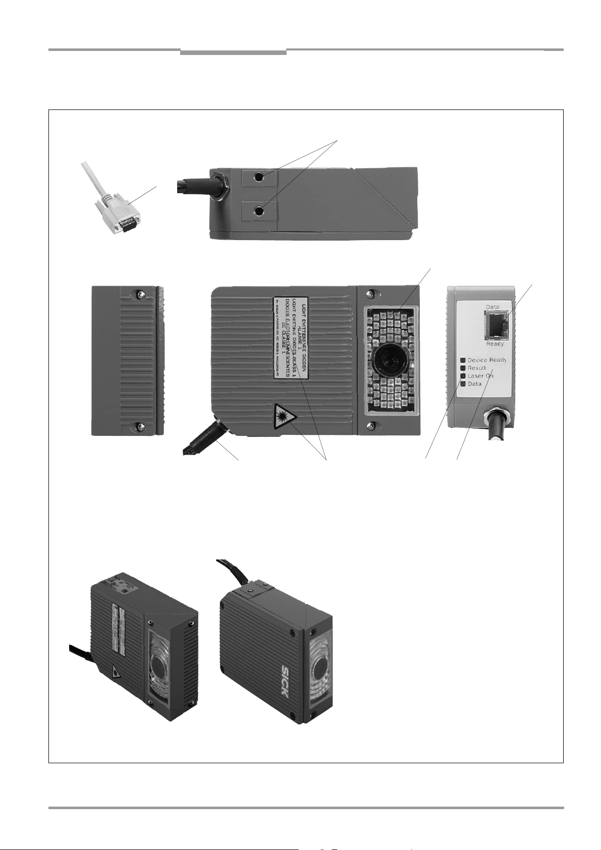
3.1.5 View of the device
2
1
3
4
Side reading window
8
Front reading window
7
6
Key:
5
1 D-Sub HD cable plug, 15-pin
2 Tapped blind holes M5,
8 mm (0.31 in) deep
3 Reading window with lens and
illumination LEDs
4 RJ 45 10baseT socket for Ethernet
connection with LEDs
5 Sound opening of the
beeper (covered)
6 LEDs (status indicators)
7 Laser warning labels
8 Connection cable
Fig. 3-1: Design of the ICR
8 010 961/0000/10-05-2005 © SICK AG · Division Auto Ident · Germany · All rights reserved 3-5
Page 24
Chapter 3 Operating instructions
Product description
ICR 84x Image Code Reader
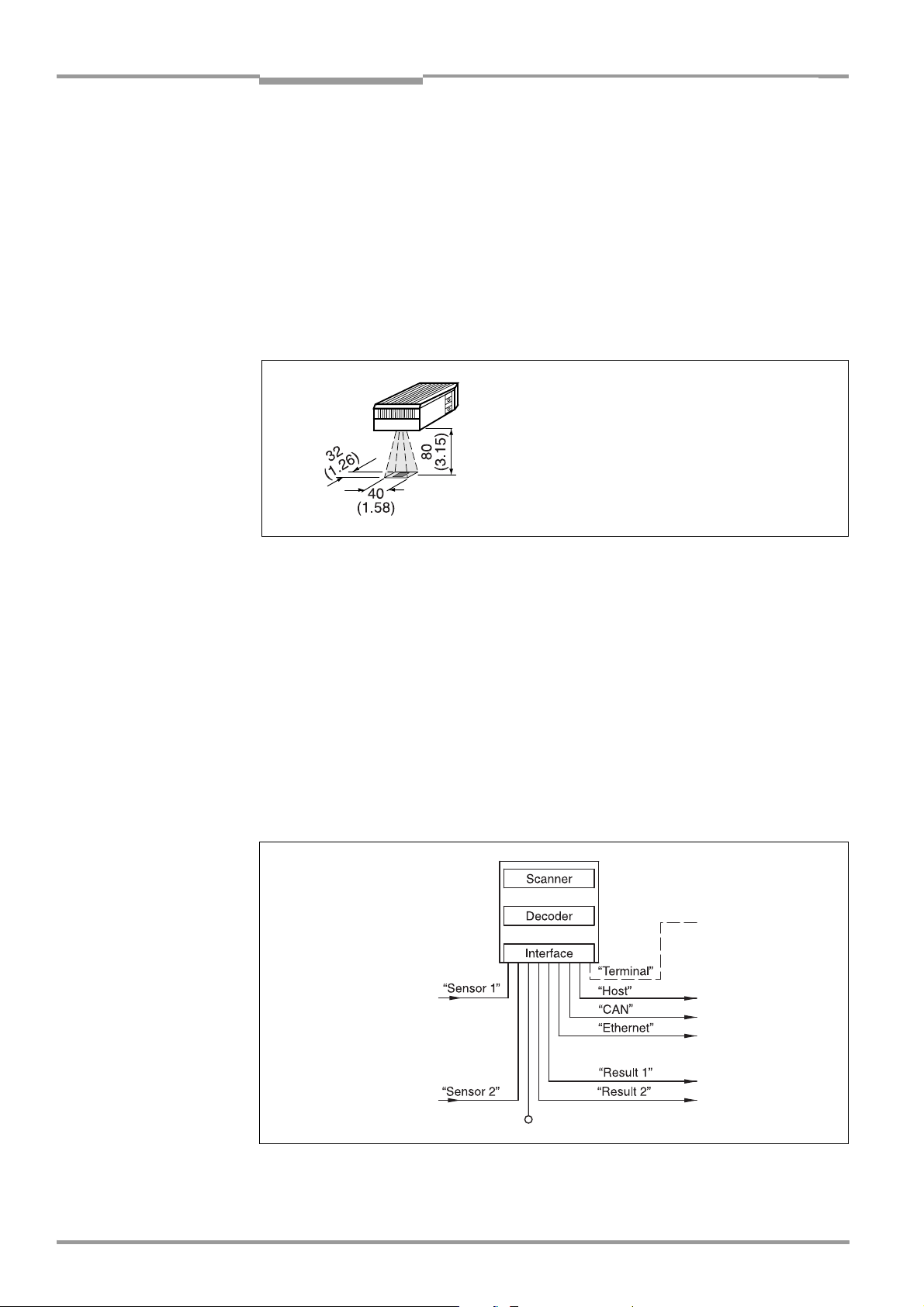
3.2 Method of operation
The ICR uses an image recording and processing system (CMOS matrix sensor with 1280
x 1024 pixels) to scan 2-D codes and bar codes with a rectangular reading area. To do so,
LEDs integrated in the housing illuminate the area to be read. The LEDs generate a red
illumination field (pulsed) with a configurable flash duration. To start a reading cycle, the ICR
switches on the illumination. It absorbs the light reflected from the reading area (Fig. 3-2)
through the lens as gray values of an image area, which are stored in an electronic image
memory (image refresh rate: 25 Hz at full memory utilization).
To prevent distorted images in the image buffer memory, the object with the code must
remain stationary while the image is being recorded.
All dimensions in mm (in)
Fig. 3-2: Reading area of the ICR in the focus position (standard type)
The reading area (surface), which is mapped in sharp focus by the ICR in its image memory,
depends on the reading distance and, depending on the resolution, must be within the
reading area (DOF). Fig. 9-4, Page 9-5 shows the available reading area.
If the appropriate configuration settings are made to reduce the image buffer memory area
(image geometry) used for the evaluation, this increases the potential image refresh rate.
The refresh rate with the VGA resolution (640 x 480 pixels) is 60 Hz, for example. The ICR
automatically adjusts the flash frequency. With a maximum of two working areas, a
maximum of just two separate strips in the image field can be evaluated.
As 2-D-codes or bar codes are detected in the image data, the ICR's decoding algorithms
determine the code(s) contents. At the end of the reading cycle or immediately after
successful decoding, the ICR outputs the code data information via its data interface (main
data interface: Host, CAN or Ethernet interface) to a host/PC for further processing.
PC
Operation
Parameterizing etc.
Photoelectric switch
Reading pulse
Signal
Path increment
Teach-in match code 1
End of reading interval
HOST
CAN bus
Image output
Status indicator
e.g. Good Read
e.g. No Read
Fig. 3-3: Block diagram: functions of the ICR
3-6 © SICK AG · Division Auto Ident · Germany · All rights reserved 8 010 961/0000/10-05-2005
Page 25

Operating instructions Chapter 3
ICR 84x Image Code Reader
Product description
The ICR is equipped with three decoders:
• The decoder for 2-D codes
• The SMART decoder (SICK Modular Advanced Recognition Technology) for decoding
bar codes with a small aspect ratio (ratio of the code height to the code length), bar
codes that are dirty or damaged, as well as bar codes that are tilted excessively
(azimuth angle)
• The tried-and-tested standard decoder of the CLV series for bar codes
The ICR derives useful diagnosis data from the reading process and transfers it to the host.
It also records operating data that can be requested at any time. The reading quality
of bar codes can be checked in the “Percentage Evaluation“ operating mode. The reading
quality of 2-D codes can be checked using the reading diagnosis data in normal Reading
mode. On request, the ICR outputs the image buffer memory content as binary or grey scale
bitmap via the Ethernet interface.
To start the reading process when an object is located in the reading area, the ICR requires
a suitable trigger. This opens a time window (“reading interval“) in the ICR for the reading
procedure. In the default setting, this trigger is supplied by an external reading pulse sensor.
Alternative trigger sources include Free Running mode and a command sent via the host
interface.
The current operating status is indicated by four LEDs. A beeper indicates the status of the
reading result. In the default setting, the “Good Read“ function is selected for this.
If the trigger is supplied externally by a sensor, the “Sensor 1“ switching input signals the
start of the reading procedure to the ICR. The “Sensor 2“ switching input is used to signal
the end of reading procedure or to enter a path increment. Alternatively, it can be used
e. g. to teach in a match code. The “Result 1“ and “Result 2“ switching outputs can be
assigned various functions and trigger external devices, such as a PLC. Using the “Result 1“
output, an external field illumination can additionally be triggered or directly powered (max.
100 mA) by the ICR.
The ICR is operated and configured via the serial auxiliary interface (auxiliary data interface)
with the user interface of the “CLV Setup“ software or via the host/auxiliary interface and
command strings. Alternatively, the Ethernet interface is available for both types of
operation.
The ICR outputs system and error messages as error codes, which can be requested from
the error memory using command strings.
8 010 961/0000/10-05-2005 © SICK AG · Division Auto Ident · Germany · All rights reserved 3-7
Page 26
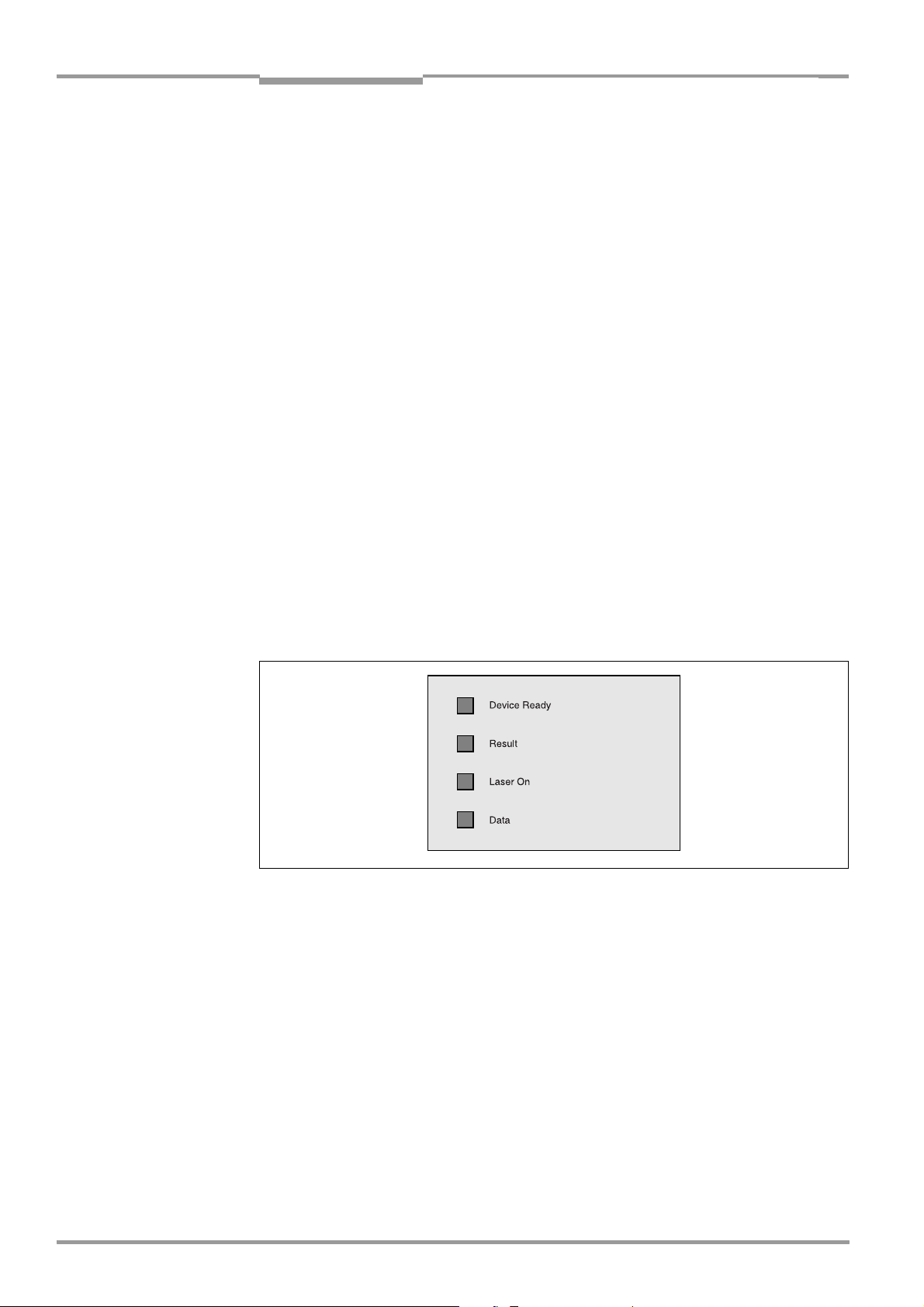
Chapter 3 Operating instructions
Product description
ICR 84x Image Code Reader
3.3 Indicators and control elements
3.3.1 Control elements
The ICR is operated and configured as described above. A variety of parameter options
allow you to adapt the device to a wide range of applications.
The following can be defined:
• The configuration of the code types to be read
• The reading, evaluation and output characteristics
• The communication parameters of the host interface, CAN or Ethernet interface
• The structure of the data output string for “Good Read“ and “No Read“ (host interface)
• The function of the auxiliary interface
Chapter 10.3 “Installation and operating instructions for the PC-based “CLV Setup“
program“, Page 10-3 describes the procedure for installing the “CLV Setup“ program and
explains how to use it. Configuration (parameterizing) is explained in Chapter 6.3.2
“Configuring the ICR for the application with the Setup Assistant“, Page 6-4.
3.3.2 Function of the LEDs
General LEDs
Four LEDs indicate the operating status, activity of the laser diode, the reading result status
and data transfer on the host interface. The LEDs (Fig. 3-4) are located on the rear of the
device toward the bottom. Table 3-2, Page 3-9 shows the meaning of the LEDs in the
different operating modes/functions.
Fig. 3-4: LEDs
3-8 © SICK AG · Division Auto Ident · Germany · All rights reserved 8 010 961/0000/10-05-2005
Page 27

Operating instructions Chapter 3
ICR 84x Image Code Reader
Operating mode LED Indication Function
Start Device Ready
Laser On
Reading mode Device Ready
Laser On
Result
Data
Percentage
Evaluation
Laser On
Result
Product description
Orange • Lights up after power-up if the self-test was successful and the wait time
for reading the profile bar codes (not suitable for ICR) has expired.
Orange • Lights up while the laser diodes for reading the profile bar codes (not
suitable for ICR) are active.
Orange • Lights up constantly
• Extinguishes with new operating mode/function
• Lights up when the laser diodes are active
(The laser diodes are activated/deactivated by reading pulse).
• Lights up constantly in the pulse mode Free Running, as the laser diodes
are always active.
Orange LED is connected to the “Result 2“ switching output. It indicates the
selected result status for the set pulse duration of the output.
• Lights up after a good read
(default setting: Good Read)
• Lights up (match code comparison active) if the read code matches the
predefined match code(s) and the corresponding result status output is
selected for the “Result 2“ output.
Orange • Flickers while the ICR transfers data to the host on the host
interface.
Orange • Lights up constantly (Free Running mode)
Orange Behavior depends on the reading quality:
• Extinguishes if reading rate < 30 %
• Flashes twice a second if reading rate is 30 % to 70 %
• Flashes five times a second if reading rate is 70 % to 90 %
• Lights up constantly if reading rate > 90 %
Table 3-2: Meaning of the general LEDs
LEDs of the Ethernet interface
Two LEDs, integrated in the RJ 45 socket 10baseT (Fig. 3-1, Page 3-5), indicate the status
of the Ethernet connection. Table 3-3 lists the meaning of the LEDs.
LED Indication Function
Ready Green Indicates the physical Ethernet connection
Data Yellow Lights up when the ICR receives or sends addressed data via
Table 3-3: Meaning of the LEDs of the Ethernet interface
Ethernet
8 010 961/0000/10-05-2005 © SICK AG · Division Auto Ident · Germany · All rights reserved 3-9
Page 28

Chapter 3 Operating instructions
Product description
ICR 84x Image Code Reader
3.3.3 Function of the beeper
The beeper uses different tone sequences and lengths (Table 3-4) to signal whether
functions have been executed successfully and whether any malfunctions have occurred.
For information on troubleshooting, see Chapter 8.5 “Troubleshooting“, Page 8-5.
In the default setting, the beeper is activated and indicates the result status “Good Read“
for the Reading mode. It is assumed in these Operating Instructions, that the beeper is
operated with the default setting in Reading mode.
The sound opening of the beeper is located on the rear, narrow side of the device and below
the LED labeling.
Operating mode Tone sequence Beeper function
Start Beep • Signals that the self-test after power-up was successful
Reading mode Beep Beep • Confirms that the device has assumed Reading mode after power
up and that the wait time of 5 s for reading the profile bar codes
(not suitable for ICR) has elapsed
Beep • Confirms a successful read (good read; default setting) and the
reading result output
Exceeding the
illumination timeout
Table 3-4: Beeper function
Tip
Beep Beep Beep • Signals that the illumination LEDs have been deactivated after the
illumination timeout of 10 min (default setting) was exceeded in
Reading mode. The reading interval is still active.
The behavior of the beeper in Reading mode can be changed on the DEVICE CONFIGURATION
tab of the CLV Setup user interface.
ON/OFF:
¾ To switch off the beeper, click on the O
FF radio button in the BEEPER group.
Output function for the result status:
1. Click the R
The R
2. Click the B
ESULT OUTPUT PARAMETERS button.
ESULT OUTPUT PARAMETERS dialog box is displayed.
EEPER list field in the RESULT FUNCTIONS section.
The list containing the available result status functions appears.
3. Click the desired function and choose “OK“.
4. Perform a download to the ICR. This is done by clicking in the toolbar.
The D
OWNLOAD PARAMETER dialog box is displayed.
5. Confirm the dialog box by selecting the P
ERMANENT save option.
The ICR operates the beeper with the values selected for the function of the result status.
3-10 © SICK AG · Division Auto Ident · Germany · All rights reserved 8 010 961/0000/10-05-2005
Page 29

Operating instructions Chapter 4
ICR 84x Image Code Reader
Installation
4 Installation
4.1 Overview of installation sequence
• Selecting the installation location for the ICR
• Aligning the ICR with the code (adjusting the reading distance)
• Mounting the ICR
• Installing the CDB 420 or CDM 420 Connection Module
• Connecting the IRC to the CDB 420 or CDM 420 Connection Module
• Adjusting the ICR
• Installing the reading pulse sensor for triggering the reading pulse
Note Don’t open the device. The producer warranty will be forfeited if the device is opened.
4.2 Installation preparations
4.2.1 Laying out the components to be installed
• ICR 84x Image Code Reader
4.2.2 Laying out accessories
• Mounting bracket no. 2 025 491 with 2 M5 x 16 mm (0.63 in) screws (not included in
the ICR scope of delivery)
– or –
Alternatively, if the bracket is supplied by the user:
Stable installation device that allows the alignment of the ICR to be varied in the x and
y axes. The ICR weighs approx. 900 g (31.75 oz) with the connection cable.
Two M5 screws for the ICR. The screw length depends on the wall thickness of the
bracket used. Depth of engagement in ICR max. 8 mm (0.31 in) from housing surface
• CDB 420 or CDM 420 Connection Module (not included in the scope of delivery of the
ICR)
• Reading pulse sensor(s) for external reading pulse trigger, e. g. photoelectric reflex
switch(es)/photoelectric proximity switch(es) (not included in the scope of delivery of
the ICR)
4.2.3 Laying out the required tools
• Two M5 screws for fastening the SICK mounting bracket (strength: 8 mm (0.31 in)) to
the installation base. The screw length depends on the wall thickness of the base
• Tool
• Protractor
8 010 961/0000/10-05-2005 © SICK AG · Division Auto Ident · Germany · All rights reserved 4-1
Page 30

Chapter 4 Operating instructions
Installation
ICR 84x Image Code Reader
4.2.4 Selecting the installation site
When you select the mounting location, the distance between the ICR and the host and
between the ICR and the code are important.
Distance between ICR and host
The ICR can be installed in a bus connection max. 1,200 m (3,936.96 ft) from the host. The
distance which can be achieved depends on the selected model of the host interface and
the set data transfer rate, however (see Table 5-5, Page 5-5). Via the Ethernet interface the
ICR can connected to the Ethernet network.
Distance between the ICR and the CDB 420 or CDM 420 Connection Module
The CDB 420 or CDM 420 Connection Module must not be located further than 10 m
(32.8 ft) from the ICR, since the “CLV Setup“ program on the PC accesses the auxiliary
interface of the ICR via this module (RS 232) by default.
4-2 © SICK AG · Division Auto Ident · Germany · All rights reserved 8 010 961/0000/10-05-2005
Page 31

Operating instructions Chapter 4
ICR 84x Image Code Reader
Installation
4.2.5 Mounting accessories
The ICR is mounted with two tapped blind holes (M5) located on the bottom narrow side of
the device. Fig. 4-1 shows the position of the threaded hole.
The dimensions of the IRC housing are shown in Fig. 9-1, Page 9-3.
All dimensions in mm (in)
Fig. 4-1: Position of the securing threads on the ICR
The ICR is installed with the mounting bracket no. 2 025 491.
The bracket is designed to support a variety of installation positions and alignments in two
planes. Fig. 4-2 shows a mounting example.
The slots in the mounting bracket allow a turning freedom of ±15° for the fine adjustment of
the ICR.
Fig. 4-2: ICR installation options using the mounting bracket no. 2 025 491
The dimensions of the mounting bracket are shown in Chapter 10.10 “Dimensional
drawings of the accessories“, Page 10-43.
8 010 961/0000/10-05-2005 © SICK AG · Division Auto Ident · Germany · All rights reserved 4-3
Page 32

Chapter 4 Operating instructions
Installation
ICR 84x Image Code Reader
4.2.6 Distance between ICR and code
a) Basic alignment with the 2-D code/bar code
The ICR is either used with the side or front reading window, depending on the application.
Fig. 4-3 shows how the reading area is aligned with the code on the object.
ICR with side reading windowICR with front reading window
Fig. 4-3: Alignment of the ICR reading area with the code
b) Reading distance to code
The distance between the reading window of the ICR and the code is determined by the
fixed focus position of the ICR and the resolution-specific depth of field for the desired cell
size/module width. The distance may not exceed the total technical limits. The resolutionspecific depth of field around the focus position is shown in Chapter 9.3.2 “Reading ranges
of ICR – preliminary –“, Page 9-4 .
Fig. 4-4 shows the exact definition of the reading distance from the reading window.
The reading distance of the standard device in the focus position is 80 mm (3.15 in).
ICR with side reading windowICR with front reading window
Y
All dimensions in mm (in)
Fig. 4-4: Definition of the reading distance
Note The size of the available reading area (surface), which is mapped in sharp focus by the ICR
in its image memory, depends on the reading distance. See Fig. 9-4, Page 9-5.
4-4 © SICK AG · Division Auto Ident · Germany · All rights reserved 8 010 961/0000/10-05-2005
Page 33

Operating instructions Chapter 4
ICR 84x Image Code Reader
Installation
Angular alignment of the ICR
The alignment of the ICR is optimum when the code is in the center of the reading area
(Fig. 4-3). All possible reading angles that can occur between the reading area and the code
must be taken into consideration (Fig. 4-5 and Table 4-2).
β
α
Reading
range
α: Azimuth angle (tilt)
β: Inclination angle (pitch)
γ: Rotation angle (skew)
γ
Reading
distance
Fig. 4-5: Reading angles between the reading area and the code
The following applies for bar codes and 2-D codes (DataMatrix ECC 200) when
reading with omni-directional decoder:
Angle Limit value
Azimuth α (tilt) 360°
Incline β (pitch) Max. ±45° (depending on the cell size and symbol size)
Rotation γ (skew) Max. ±45° (depending on the cell size and symbol size)
Table 4-1: Permissible reading angle between the reading area and the bar code/2-D code when
reading with omni-directional decoder
The following applies for bar codes when reading with standard/SMART decoder:
Angle Limit value
Azimuth α (tilt) Max. ±45° (in scanning axis and in focus position 100 mm (3.94 in) for
module width 0.2 to 0.5 mm (7.9 to 19.7 mil))
Incline β (pitch) Max. ±45° (depending on the module width)
Rotation γ (skew) Max. ±45° (depending on the module width)
Table 4-2: Permissible reading angles between the reading area and bar code when reading with
standard/SMART decoder
Note The length of readable bar code is reduced with respect to the decodable length as a result
of the distance-dependent dimensions of the reading area (surface) (see examples in
Table 9-2, Page 9-2).
8 010 961/0000/10-05-2005 © SICK AG · Division Auto Ident · Germany · All rights reserved 4-5
Page 34

Chapter 4 Operating instructions
Installation
ICR 84x Image Code Reader
Preventing surface reflections
The ICR can be installed parallel to the object surface.
ICR with front reading window ICR with side reading window
(Top view) (Side view)
Fig. 4-6: Installing the ICR parallel to the object surface
4.2.7 Count direction of the code position CP
Explanation The ICR can scan and decode several codes with each read.
In doing so, it determines the local reading diagnosis data for each code in the image
memory.
Fig. 4-7 shows the count direction of the code position along the reading window.
By determining the value, the device can separate identical codes (code type, code length,
and data content) and assign the code data in the reading result to its position on the object.
100 %
CP
0 %
Fig. 4-7: Count direction of the code position CP for bar codes along the reading window
100 %
CP
0 %
For 2-D codes, the ICR determines the spatial position of the finder patterns in the image
memory. It outputs its corner points in the shape of two-dimensional coordinates in the
reading result of the auxiliary interface as the “PT“ reading diagnosis data (see “1. Output of
reading result: 2-D code (DataMatrix ECC 200)“, Page 6-30).
For bar codes, the ICR determines the position of the first dark line of the start character in
the image memory. It outputs the value in the reading result of the auxiliary interface as
reading diagnosis data “CP“ (see “2. Output of reading result: Bar code“, Page 6-32).
When the ICR 840 is in the focus position (reading distance 80 mm ((3.15 in)), one pixel in
the image memory is approx. 33 µ, whereby 1% of the CP is approx. 0.4 mm lengthwise of
the reading area.
4-6 © SICK AG · Division Auto Ident · Germany · All rights reserved 8 010 961/0000/10-05-2005
Page 35

Operating instructions Chapter 4
ICR 84x Image Code Reader
Installation
Tip
In the default setting, the ICR does not output the values “PT“ or “CP“ in the reading result
of the host interface. If this is required to evaluate the result in the host, the values can be
included in the “reading data“ block of the output string using the CLV Setup program.
Configuring reading data:
1. Select the D
2. Click the R
The dialog window E
ATA STRINGS tab.
EADING DATA field.
DIT PARAMETER: TFS dialog box is displayed.
3. Use the mouse to place the cursor before or after the “BC“ (bar code) placeholder.
4. In the drop-down list box below it, click the parameter PT for 2-D codes or CP for bar
codes. PT or CP is added in the selected position in the input field.
5. Confirm the dialog box with “OK“.
6. Perform a download to the ICR. This is done by clicking in the toolbar.
The D
OWNLOAD PARAMETER dialog box is displayed.
7. Confirm the dialog box by selecting the P
ERMANENT save option.
The ICR outputs the PT or CP value for each code in the reading result via the host
interface. The values are always multi-digit numbers located in the selected position in
the reading data.
8 010 961/0000/10-05-2005 © SICK AG · Division Auto Ident · Germany · All rights reserved 4-7
Page 36

Chapter 4 Operating instructions
Installation
ICR 84x Image Code Reader
4.3 Installing and adjusting the device
4.3.1 Installing the ICR
1. Prepare the base for installing the bracket as described in Chapter 4.2.2 “Laying out
accessories“, Page 4-1.
Risk of damage to the housing
The maximum depth of engagement of the two tapped blind holes M5 is 8 mm (0.31 in).
Longer screws will damage the housing.
¾ Use screws with the correct length.
2. Screw the screws M5 through the bracket into the tapped blind holes of the ICR.
3. Tighten the screws slightly so that the ICR can to be varied in the x and y axes.
4. Place the object containing the 2-D code within the visible range of the ICR in the
position at which it is to be read (with the conveyor switched off).
5. Align the ICR with the code in such a way that
– The wide side of the device with the laser warning labels is nearly parallel with the
code surface, when using a side reading window.
– The narrow side of the device with the LEDs is nearly parallel with the code surface,
when using a front reading window.
Reading distance:
The reading distance of the standard device in the focus position is 80 mm (3.15 in) in
front of the reading window. See Fig. 4-4, Page 4-4.
All of the possible reading angles must be taken into consideration (see Fig. 4-5,
Page 4-5).
6. If relevant to the evaluation, pay attention to the count direction of the code position if
applicable (see Fig. 4-7, Page 4-6).
7. Mark the bracket of the ICR on the base (supporting stand), drill the required holes and
install the bracket on the base.
4-8 © SICK AG · Division Auto Ident · Germany · All rights reserved 8 010 961/0000/10-05-2005
Page 37

Operating instructions Chapter 4
ICR 84x Image Code Reader
Installation
4.4 Installing external components
4.4.1 Installing the CDB 420 or CDM 420 Connection Module
1. Install the CDB 420 or CDM 420 Connection Module near the ICR. The distance
between the CDB 420 or CDM 420 and ICR must not exceed 10 m (32.8 ft).
2. Install the CDB 420 or CDM 420 in such a way that the device can be accessed when
opened. The auxiliary interface of the ICR, used for parameterizing/diagnosis, is
accessed via the internal “Aux“ connector.
Detailed information on the installation and electrical installation procedures is provided in
the “CDB 420 Connection Module“ Operating Instructions (order no. 8 010 001, German/
English version) respectively in the “CDM 420 Connection Module“ Operating Instructions
(order no. 8 010 004, German/English version).
4.4.2 Installing the external reading pulse sensor
If the ICR is triggered by an external reading pulse sensor, the sensor must be installed in
the vicinity of the ICR. The “Sensor 1“ switching input is selected as the default trigger source
for this trigger type.
Fig. 4-8 shows two examples of where a photoelectric reflex switch can be installed. This
depends on the distance a from the code to the front of the object. Depending on the
application, you may need to attach the sensor in such a way that codes on objects of
different sizes can be read completely during the reading interval (no conveyor movement).
Code in the middle or at the end of the object being moved Code at the beginning of the object being moved
Fig. 4-8: Line scanner: Installation example for the external reading pulse sensor
1. Attach the reading pulse sensor to the installation location.
2. Connect the reading pulse sensor to the “Sensor 1“ switching input of the ICR via the
CDB 420 or CDM 420 Connection Module (see Chapter 5.5.8 “Connecting the “Sensor
1“ switching input“, Page 5-13).
3. Connect the ICR to the CDB 420 or CDM 420 Connection Module and switch on the
power supply to the module (see Chapter 5.5.3 “Connecting the power supply“,
Page 5-7).
After the ICR has started, it emits a tone to indicate that the self-test was successful.
After a short while, it outputs two consecutive tones to indicate that it has switched to
Reading mode. The “Device Ready“ LED lights up.
4. Connect the PC to the auxiliary interface of the ICR. For this purpose, connect a 3-core
RS 232 data cable (null modem cable) to the internal 9-pin “Aux“ plug of the module.
(see Chapter 5.5.7 “Connecting the PC“, Page 5-12).
8 010 961/0000/10-05-2005 © SICK AG · Division Auto Ident · Germany · All rights reserved 4-9
Page 38

Chapter 4 Operating instructions
Installation
ICR 84x Image Code Reader
– or –
Connect the PC to the Ethernet interface of the ICR.
(see Chapter 5.5.6 “Connecting the Ethernet interface“, Page 5-10)
5. Start Windows and “CLV Setup“ on your PC.
(see Chapter 10.3.3 “Starting “CLV Setup““, Page 10-6).
6. Click in the toolbar in CLV Setup.
The Terminal Emulator dialog box is then displayed.
7. Click R
EADING MODE under DEVICE MODE.
Monitor the reading result during each of the subsequent steps!
8. Represent objects with 2-D codes to the ICR one after another (no conveyor
movement).
9. Check for proper reading pulse triggering and the reading result.
Parameterizing an external sensor as a trigger source (not applicable in the case of
default setting):
1. Select the D
2. Click the R
The R
3. Choose S
EVICE CONFIGURATION tab.
EADING TRIGGER PARAMETERS button.
EADING TRIGGER PARAMETERS dialog box is then displayed.
ENSOR INPUT in the START OF READING INTERVAL section and confirm your
selection.
4. Perform a download to the ICR. This is done by clicking in the toolbar.
The D
OWNLOAD PARAMETER dialog box is displayed.
5. Confirm the dialog box by selecting the P
ERMANENT save option.
The ICR operates with the “Sensor 1“ switching input as an external trigger source.
The reading pulse starts when power is applied.
4.4.3 Installing the incremental encoder
An encoder is required for using a track controlled delay of the external reading trigger.
1. Install the incremental encoder (e. g. no. 2 022 714) near the ICR but in front of it,
preferably against the direction of the conveyor belt. The increment pulses must
originate from the area of the conveyor belt which the ICR is reading.
2. Ensure that the incremental encoder is contacting the conveyor and that the friction
wheel turns without slipping.
3. Connect incremental encoder to the "Sensor 2" switching input of the ICR). See
Chapter 5.5.9 “Connecting the “Sensor 2“ switching input“, Page 5-14.
4.5 Removing the device
1. Switch off the power supply to the CDB 420 or CDM 420 Connection Module.
2. Loosen the screws and remove the ICR cable plug from the CDB 420 or CDM 420
Connection Module.
3. When using the Ethernet interface, detach the connection cable from the socket on the
ICR.
4. Unscrew the ICR from the installation device.
When removing the device from service for the last time, please dispose of it in an
environmentally-friendly manner, as described in Chapter 7.3 “Disposal“, Page 7-2.
4-10 © SICK AG · Division Auto Ident · Germany · All rights reserved 8 010 961/0000/10-05-2005
Page 39

Operating instructions Chapter 5
ICR 84x Image Code Reader
Electrical installation
5 Electrical installation
5.1 Overview of the installation sequence
• Connecting the ICR to the CDB 420 or CDM 420 Connection Module
• Connecting the data and functional interfaces of the ICR in the module
• Connecting the Ethernet interface for image output and parameterization (recommen-
ded).
Alternatively without image output: Connect the PC to the auxiliary interface on the ICR.
• Optional: connecting the external illumination
• Connecting the power supply to the connection module
5.1.1 SICK Connection Modules (Overview)
Connection
Module
CDB 420-001
CDB 420-101
CDM 420-0001 – Connecting one ICR
Tab. 5-1: Connection modules for the ICR
Design Purpose
– Connecting one ICR
– 1 x 15-pin D Sub HD socket, 4 x cable gland
(CDB 420-101: 2 x cable gland, 2 x M12 plug
connection (1 x plug, 1 x socket))
– Operating voltage 10 to 30 V DC,
when using with the ICR 84x: 15 to 30 V DC
– Enclosure rating max. IP 65
– Temperature range –35 to +40 °C
(–31 to +104 °F)
– 1 x 15-pin D Sub HD socket,
6 x cable gland
– Operating voltage 10 to 30 V DC,
when using with the ICR 84x: 15 to 30 V DC
– Enclosure rating max. IP 65
– Temperature range –35 to +40 °C
(–31 to +104 °F)
For technical data on the modules see Chapter 10.9.2 “Connection modules“, Page 10-40.
5.2 Electrical connections and cables
The electrical connection of the ICR consists of a 15-pin D-Sub HD cable plug and an 8-pin
RJ 45 socket 10baseT on the device. It supplies the following interfaces:
• Four serial data interfaces (host, CAN, Ethernet and auxiliary interface)
• Two switching inputs (external reading pulse and multifunctional input)
• Two switching outputs (for result status function, or connecting to a PLC for example)
• Power supply
¾ All of the connections must be wired with copper cables with a minimum wire diameter
of 0.09 mm
8 010 961/0000/10-05-2005 © SICK AG · Division Auto Ident · Germany · All rights reserved 5-1
2
(approx. 17 AWG)!
Page 40

Chapter 5 Operating instructions
Electrical installation
ICR 84x Image Code Reader
5.2.1 Pre-fabricated cables (Overview)
Temperature range 0 to +40 °C (+32 to +104 °F).
Connection of
ICR to
CDB 420
CDM 420
Non-SICK
power pack
PC (RS 232) No. 2 014 054 3 m
Ethernet No. 6 026 083 3 m
PC with
Ethernet card
Tab. 5-2: Cables for connecting the ICR
Cable Length Purpose
No. 6 010 075 2 m
(6.56 ft)
No. 6 010 137 2 m
(6.56 ft)
(9.84 ft)
(9.84 ft)
No. 6 026 084 3 m
(9.84 ft)
Extension cable for data and function interfaces, with
15-pin D Sub HD socket and plug
Connection cable for data and functions interfaces,
with 15-pin D Sub HD socket and open end
RS 232 data cable (null modem cable) with two 9-pin
D Sub sockets (TxD and RxD are crossed)
Ethernet data cable (patch cable) with two 8-pin
RJ-45 plugs (grey)
Ethernet cross-over cable with two 8-pin RJ-45 plug
(red)
For technical data on the cables Chapter 10.9.4 “Cables and plug-in connections“,
Page 10-42.
5.2.2 Connections/cables for the CDB 420 or CDM 420 Connection Module
The CDB 420 or CDM 420 Connection Module is suitable for connecting the ICR to
peripherals (distribution function) and the power supply. The module can be used to
establish a connection to the host (point-to-point) and integrate the device into the CAN
scanner network. The CDB 420 is available in two variants. All modules can be operated with
an operating temperature to –35 to +40 °C (–31 to +104 °F).
Fig. 5-1 shows the connection principle of the CDB 420 or CDM 420 for one ICR.
ICR 84x
CDB 420/CDM 420
Photoelectric switch
Reading pulse
Photoelectric switch
Path increment
Teach-in
Match code 1
End of reading interval
– – cable if necessary
Fig. 5-1: Block diagram: Connection of the ICR to the CDB 420 or CDM 420 Connection Module
Connection Module
AUX
15 to 30 V DC
HOST/PLC
CAN bus
PLC
PLC
5-2 © SICK AG · Division Auto Ident · Germany · All rights reserved 8 010 961/0000/10-05-2005
Page 41

Operating instructions Chapter 5
ICR 84x Image Code Reader
Electrical installation
Connect and configure the CDB 420 or CDM 420 Connection Module as described in the
“CDB 420 Connection Module“ Operating Instructions (order no. 8 010 001, German/
English version) respectively in the “CDM 420 Connection Module“ Operating Instructions
(order no. 8 010 004, German/English version).
Note Diagramms showing you how to connect the CDB 420 and CDM 420 Connection Modules
are also available in the “CLV Connect“ PC program. This software is available on the
“Manuals & Software“ CD, which is included in the scope of delivery of the ICR. The software
can also be downloaded from the SICK home page (www.sick.com) at “Service&Support/
Downloadpool“. It can be called up using a standard HTML browser (e.g. Internet
Explorer
TM
).
Optional modules for building-in into the CDB 420:
• CMC 400 Connection Module Cloning for saving the parameters of the ICR externally
Optional modules for building-in into the CDM 420:
• CMP 400 Power Supply Module in optional cover for supplying the ICR without heater
directly from an AC power line
• CMC 400 Connection Module Cloning for saving the parameters of the ICR externally
• CMD 400 Connection Display Module in optional cover for representation of reading
results and reading diagnosis data
• CMF 400 Bus Modules (field bus gateways) for connecting the CLV to Profibus DP or
DeviceNet
For detailed descriptions about functions and installation see the corresponding Fitting/
Operatings Instructions (see Chapter 10.11 “Supplementary documentation“, Page 10-44).
8 010 961/0000/10-05-2005 © SICK AG · Division Auto Ident · Germany · All rights reserved 5-3
Page 42

Chapter 5 Operating instructions
Electrical installation
ICR 84x Image Code Reader
5.3 Pin assignments
5.3.1 Cable plug
5 6
1
11
Pin Signal Function
1 15 to 30 V DC Power supply
2 RxD (Aux) Auxiliary interface (receiver)
3 TxD (Aux) Auxiliary interface (transmitter)
4 Sensor 2 Switching input, variable function
5 GND Ground
6 RD+ (RS 422/485) Host interface (receiver)
7 RD– (RS 422/485); RxD (RS 232) Host interface (receiver)
8 TD+ (RS 422/485) Host interface (transmitter)
9 TD– (RS 422/485); TxD (RS 232) Host interface (transmitter)
10 CAN H CAN bus (IN/OUT)
11 CAN L CAN bus (IN/OUT)
12 Result 1 Switching output, variable function
13 Result 2 Switching output, variable function
14 Sensor 1 Switching input for external reading pulse
15 SensGND Common ground for all inputs
– – Shield
10
15
Table 5-3: Pin assignment of the 15-pin D-Sub HD plug
5.3.2 RJ 45 socket 10baseT (Ethernet)
Pin Signal Function
1 TX+ Transmitter+
2 TX– Transmitter–
3 RX+ Receiver+
6 RX– Receiver–
4, 5, 7, 8 n.c. Not connected
Table 5-4: Pin assignment of the 8-pin RJ 45 10baseT socket
5-4 © SICK AG · Division Auto Ident · Germany · All rights reserved 8 010 961/0000/10-05-2005
Page 43

Operating instructions Chapter 5
ICR 84x Image Code Reader
Electrical installation
5.4 Electrical installation preparations
5.4.1 Requirements for the host interface
The host interface of the ICR can be operated as an RS 422/485 or an RS 232 interface.
Table 5-5 shows the recommended maximum cable lengths as a function of the selected
data transfer rate.
Interface type Transmission rate Distance from host
RS 232 Up to 19,200 bd Max. 10 m (32.8 ft)
38,400 to 57,600 bd Max. 3 m (9.84 ft)
RS 422/485
1) with suitable line termination according to specifications
Table 5-5: Maximum cable lengths between the ICR and host
1)
Recommendation ¾ To prevent interference, do not lay the cable parallel with power supply and motor
cables over long distances, e.g. in cable ducts.
Max. 38,400 bd Max. 1,200 m (3,937 ft)
Max. 57,600 bd Max. 500 m (1,640 ft)
5.4.2 Power supply
The ICR requires a power supply of 15 to 30 V DC (functional extra-low voltage) in
accordance with the standard IEC 364-4-41. The functional extra-low voltage can be
generated by using a safety isolating transformer pursuant to IEC 742. The ICR has a typical
power consumption of typically 7 W, max. 10 W (when switching outputs are not connected).
The ICR is supplied with 15 to 30 V DC via the CDB 420 or CDM 420 Connection Module.
If an optional CMF 400 fieldbus gateway or a CMD 400 Connection Module Display is
additionally used in the CDM 420, the ICR is supplied with 18 to 30 V DC.
If the CMP 400 Power Supply Module is used in the CDM 420, a mains voltage of 100 to
250 V AC/50 to 60 Hz is required.
Power-up delay
The selected device number (default setting: 1) affects the power-up delay of the device.
This is useful if a large number of ICRs (e.g. in the CAN scanner network) are to be supplied
from one power source. Table 5-6 contains a list of the available intervals.
Device number GN Power-up
delay
1; 11; 21; 31 0 ms 6; 16; 26 2 000 ms
2; 12; 22 400 m 7; 17; 27 2 400 ms
3; 13; 23 800 ms 8; 18; 28 2 800 ms
4; 14; 24 1 200 ms 9; 19; 29 3 200 ms
5; 15; 25 1 600 ms 10; 20; 30 3 600 ms
Table 5-6: Power-up delay as a function of the device number GN
Device number GN Power-up
delay
Tip
The device number can be selected on the DEVICE CONFIGURATION tab in the CLV Setup
program.
8 010 961/0000/10-05-2005 © SICK AG · Division Auto Ident · Germany · All rights reserved 5-5
Page 44

Chapter 5 Operating instructions
Electrical installation
ICR 84x Image Code Reader
5.4.3 Non-SICK power supply unit/connections without the SICK connection module
If a non-SICK power supply unit is used instead of the CDB 420 or CDM 420, it must provide
a functional extra-low voltage in accordance with the standard IEC 364-4-41 and a
continuous power output of at least 12 W.
The output circuit must be reliably electrically isolated from the input circuit. Do do so,
use a safety isolating transformer pursuant to IEC 742.
The minimum wire cross-section for the power supply (pin 1/pin 5) must be at least
0.15 mm
2
(approx. 26 AWG).
¾ Use the cable no. 6 010 137 with 15-pin D-Sub HD cable socket and open end to
connect the ICR.
The color assignment of the wires is shown in Table 5-7.
Pin Signal Wiring color
1 15to30VDC Red
2 RxD (aux) Purple
3 TxD (aux) Yellow
4 Sensor 2 Red/black
5 GND Black
6 RD+ (RS 422/485) Light blue
7 RD– (RS 422/485); RxD (RS 232) Blue
8 TD+ (RS 422/485) Turquoise
9 TD– (RS 422/485); TxD (RS 232) Green
10 CAN H Gray
11 CAN L Pink
12 Result 1 Brown
13 Result 2 Orange
14 Sensor 1 White
15 SensGND White/black
– Shield White/green
Table 5-7: Wiring color assignment of cable no. 6 010 137 (open end)
Note The wiring color assignment shown above only applies for the upper cable, not for the
connection cable with the cable plug which runs to the ICR housing.
5-6 © SICK AG · Division Auto Ident · Germany · All rights reserved 8 010 961/0000/10-05-2005
Page 45

Operating instructions Chapter 5
ICR 84x Image Code Reader
Electrical installation
5.5 Performing electrical installation
5.5.1 Overview of connection procedure
• Connecting the power supply
• Connecting the host interface
– or –
Connecting the CAN interface
• Connecting the auxiliary interface (connecting the PC for parameterization)
• Connecting the Ethernet interface and the PC to Ethernet for image output
(recommended)
• Connecting the “Sensor 1“ and “Sensor 2“ switching inputs
• Connecting the “Result 1“ and “Result 2“ switching outputs
5.5.2 Tools
• Tool
• Digital measuring device (current/voltage measurement)
5.5.3 Connecting the power supply
If the ICR is powered via the CDB 420 or CDM 420 Connection Module, the power supply
does not have to be wired separately.
1. Ensure that the power supply to the CDB 420 or CDM 420 is switched off.
2. Connect the 15-pin cable plug on the ICR to the corresponding device socket on the
CDB 420 or CDM 420 and screw it tightly. The connection cable can be extended by
2 m (6.56 ft) using the extension cable no. 6 010 075.
The data and functional interfaces of the ICR are connected to the connection module.
– or –
External power supply unit:
¾ Connect the power supply to the red wire (pin 1, +V
) and the black wire (pin 5, GND)
S
of the cable no. 6 010 137 (see also Table 5-7).
8 010 961/0000/10-05-2005 © SICK AG · Division Auto Ident · Germany · All rights reserved 5-7
Page 46

Chapter 5 Operating instructions
Electrical installation
ICR 84x Image Code Reader
5.5.4 Connecting the host interface
(3)
RS 232
ICR 84x
RS 422
ICR 84x
CAN bus: Connection diagram for SICK CAN Scanner Network
see "CLV Connect" program on CD ROM
Fig. 5-2: Connections of the host interface
(2)
(5)
Host
( )= 9-pin D-Sub
plug on the PC
Host
Risk of damage to the interface module
Electrical components in the ICR can be damaged if the host interface is connected
incorrectly.
¾ Connect the host interface as shown in Fig. 5-2.
¾ Check the connections carefully before you switch on the ICR.
¾ Connect the host interface on the ICR to the host using shielded cables (EMC
requirements). Ensure that the maximum cable lengths are not exceeded (Table 5-5,
Page 5-5).
In the default setting, the ICR communicates with the host via the host interface using the
values shown in Table 5-8.
Parameter Value
Physical design RS 232
Data transmission rate 9,600 bd
Data bits 8
Parity None
Stop bits 1
Protocol SICK (start character: STX, stop character: ETX, no request for
repeat: none, timeout: 50 ms)
Table 5-8: Communication parameters for the host interface (default setting)
5-8 © SICK AG · Division Auto Ident · Germany · All rights reserved 8 010 961/0000/10-05-2005
Page 47

Operating instructions Chapter 5
ICR 84x Image Code Reader
Electrical installation
For connecting the host interface via the CDB 420 or CDM 420 Connection Module, see the
“CDB 420 Connection Module“ Operating Instructions (order no. 8 010 001, German/
English version) respectively the “CDM 420 Connection Module“ Operating Instructions
(order no. 8 010 004, German/English version).
Terminating the RS 422 interface
The interface can be terminated in the CDB 420 or CDM 420 Connection Module.
See “CDB 420 or CDM 420 Connection Module“ Operating Instructions.
Activating the RS 422 interface
The RS 422 interface can be activated with the CLV Setup program:
1. Select the H
2. Choose the “RS 422/485“ option from the H
F
ORMAT.
OST INTERFACE tab.
ARDWARE drop-down list under DATA
3. Perform a download to the ICR.
This is done by clicking in the toolbar.
The D
OWNLOAD PARAMETER dialog box is displayed.
4. Confirm the dialog box by selecting the P
ERMANENT save option.
The ICR now uses the RS 422 version of the host interface.
Tip The communication parameters can be changed, if necessary, on the H
To do so, change the values under D
ATA FORMAT and INTERFACE PROTOCOL.
OST INTERFACE tab.
5.5.5 Connecting the CAN interface
For information on the connection and parameterization of the ICR for use in a SICK-specific
CAN scanner network or in a CANopen network, see the “Application of the CAN interface“
Operating Instructions (no. 8 009 180, English version).
8 010 961/0000/10-05-2005 © SICK AG · Division Auto Ident · Germany · All rights reserved 5-9
Page 48

Chapter 5 Operating instructions
Electrical installation
ICR 84x Image Code Reader
5.5.6 Connecting the Ethernet interface
The Ethernet interface has four functions:
• Fast image output of the scanned code to the PC via FTP.
To carry out this function, choose the E
THERNET and IMAGE ACQUISITION tabs in CLV Setup
or use the Setup Assistant.
• The read result can be output via TCP/IP instead of via the host interface.
To carry out this function, choose the H
OST INTERFACE tab in CLV Setup.
• The auxiliary interface data (read result + reading diagnosis data) can be output via
TCP/IP instead of via the host interface.
To carry out this function, choose the A
UXILIARY INTERFACE tab in CLV Setup.
• Access to the ICR for parameterization with CLV Setup.
ICR 84x
RS 232
Aux
RS 232/422
Host
CAN
Port 2111: AUX
Ethernet
Fig. 5-3: Block diagram: Function of the Ethernet interface
Port 2112: Host
Port 21: FTP
PC
CLV Setup
FTP Server
Note If auxiliary interface communication is routed via the Ethernet interface by making the appro-
priate parameter settings (see above), the physical auxiliary interface (RS 232) is disabled.
If host interface communication is routed via the CAN or Ethernet interface by making the
appropriate parameter settings (see above), the physical host interface (RS 232/RS 422)
is disabled.
If the PC is connected to the ICR via the Ethernet interface for parameterization purposes,
however, the auxiliary interface and host interface of the ICR remain active (without diversion).
Recommendation To reduce electromagnetic emissions, attach a ferrite filter to the cable near the ICR in the
snap-in folding housing.
In the default setting, the ICR communicates with the values listed in Table 5-9.
Parameter Value
Data transmission rate 10 Mbit/s (cannot be changed)
IP address 192.168.0.1
IP gateway address 0.0.0.0
IP mask 255.255.255.0
IP port (Host) 2112
IP port (Aux) 2111
FTP port 21, FTP client disabled
Table 5-9: Ethernet interface communication parameters (default setting)
Table 3-3, Page 3-9 describes the function of the two LEDs on the connection socket.
5-10 © SICK AG · Division Auto Ident · Germany · All rights reserved 8 010 961/0000/10-05-2005
Page 49

Operating instructions Chapter 5
ICR 84x Image Code Reader
Electrical installation
Connection:
The Ethernet interface works parallel to the host interface without any additional required
activation. It is connected to the network with a standard data cable (patch cable). When
connected to a PC (point-to-point connection), on the other hand, a crossover line is
required (see Table 5-2, Page 5-2).
¾ Connect the Ethernet socket of the ICR to the Ethernet socket using a patch cable.
If the green “Ready“ LED at the socket of the ICR lights up, the physical connection has
finished successful.
Required settings in the PC and ICR (manually):
1. Select the IP address and subnet mask of the PC in the “Network“ dialog box under
“Control Panel“ in Windows.
Depending on the Windows version and the network architecture, administration rights
may be necessary here.
2. Define the IP address and subnet mask of the ICR with CLV Setup:
Enter the corresponding values on the E
Perform a download to the ICR with the P
THERNET tab.
ERMANENT save option!
3. Restart the ICR.
4. Select I
5. Activate the TCP/IP protocol of the PC in the I
Enter the IP address selected on the “Ethernet“ tab in the IP
NTERFACE under OPTIONS in the menu bar.
NTERFACE OPTIONS dialog box.
ADDRESS section.
Close the dialog box with “OK“.
Setting the addresses/mask using the Setup Assistant under CLV Setup:
See Chapter 6.3.2 “Configuring the ICR for the application with the Setup Assistant“,
Page 6-4.
Note When using the Ethernet Assistant there are some restrictions:
– A firewall installed on the host (PC) can block the telegrams between the host and the
ICR.
– If the subnet mask of the IP configuration of the ICR is set to 255.255.255.255, the
ICR will receive telegrams but cannot send any telegram.
– There is no forwarding of telegrams to an other subnet which is connected with the sub-
net of the ICR by a router.
8 010 961/0000/10-05-2005 © SICK AG · Division Auto Ident · Germany · All rights reserved 5-11
Page 50

Chapter 5 Operating instructions
Electrical installation
ICR 84x Image Code Reader
5.5.7 Connecting the PC
The ICR is operated and configured with the PC-based “CLV Setup“ program. In order to do
so, you must connect the device to the PC via the auxiliary interface by default. Alternatively
you can use the Ethernet interface. Unlike the host interface, the auxiliary interface has a
fixed data format and a fixed data transfer rate. Fig. 5-4 shows how the auxiliary interface is
connected. The cable length must not exceed 10 m (32.8 ft)
RS 232
ICR 84x
( )= 9-pin D-Sub
plug on the PC
Fig. 5-4: Connection of the auxiliary interface
PC
1. Switch off the PC and power supply to the SICK CDB 420 or CDM 420 connection
module.
2. Connect the PC to the internal, 9-pin ”Aux“ plug of the connection module.
To do so, use a 3-core RS 232 data cable (null modem cable), e.g. no. 2 014 054
(RxD and TxD crossed).
– or –
With the SICK Connection Module:
Connect the PC as shown in Fig. 5-4.
3. Switch on the PC and power supply to the SICK connection module.
4. Set the communication parameters (see Chapter 10.3.3 “Starting “CLV Setup““,
Page 10-6). The ICR communicates with the PC via the auxiliary interface using the fixed
values shown in Table 5-10.
Parameter Value
Physical design RS 232
Data transmission rate 9,600 bd
Data bits 8
Parity None
Stop bits 1
Protocol SICK (start character: STX, stop character: ETX)
Table 5-10: Communication parameters for the auxiliary interface
Tip
In the default setting, the auxiliary interface outputs the reading result in “Reading Diagnosis“
mode.
You can change the operating mode to M
STATISTICS FOR RDT 400 on the AUXILIARY INTERFACE tab in the CLV Setup program.
ONITOR HOST INTERFACE, AUXILIARY INPUT or CODE
5-12 © SICK AG · Division Auto Ident · Germany · All rights reserved 8 010 961/0000/10-05-2005
Page 51

Operating instructions Chapter 5
ICR 84x Image Code Reader
Electrical installation
5.5.8 Connecting the “Sensor 1“ switching input
If a reading procedure is to be triggered on the ICR by an external sensor, the reading pulse
sensor must be connected to the “Sensor 1“ switching input. The trigger type is selected in
the default setting of the ICR. Fig. 5-5 shows the connections for the “Sensor 1“ switching
input. Table 5-11 contains the characteristic data for this input.
¾ Connect the reading pulse sensor as shown in Fig. 5-5.
ICR 84x
V
i
VS= +15 to +30 V DC *) V
Fig. 5-5: Connections of the “Sensor 1“ switching input
Switching mode Current at the input starts the reading interval on the ICR.
(default setting: not inverted (active high), debouncing time: 10 ms,
start delay: 0 ms, stop delay: 0 ms)
Characteristics – Optodecoupled, non-interchangeable
– Can be connected to PNP output on a sensor
Electrical values Low: –1 V ≤ V
–0.3 mA ≤ Ii ≤ +0.3 mA +1.4 mA ≤ |Ii| ≤ +18 mA
i max
≤ +1 V High: +8 V ≤ |Vi| ≤ +28 V
i
PNP sensor Switch
= 28 V!
Table 5-11: Characteristic data of the “Sensor 1“ switching input
Tip
You can change the switching mode (polarity, debouncing time, start/stop delay and
response for first pulse after power-up) of the “Sensor 1“ switching input on the D
C
ONFIGURATION tab in the CLV Setup program.
¾ Edit S
ENSOR 1 section and click the READING TRIGGER PARAMETERS button.
Edit dialog box.
Download all changes to ICR.
For connecting the “Sensor 1“ switching input via the CDB 420 or CDM 420 Connection
Module, see the “CDB 420 Connection Module“ Operating Instructions (order no. 8 010
001, German/English version) respectively the “CDM 420 Connection Module“ Operating
Instructions (order no. 8 010 004, German/English version).
Note An external pulse is not required for “Percentage Evaluation“ mode.
EVICE
8 010 961/0000/10-05-2005 © SICK AG · Division Auto Ident · Germany · All rights reserved 5-13
Page 52

Chapter 5 Operating instructions
Electrical installation
ICR 84x Image Code Reader
5.5.9 Connecting the “Sensor 2“ switching input
The input has the following functions:
• Path increment input for track controlled delaying of the external reading trigger
• Trigger source for teaching in the match code 1
• External trigger source for end of the reading interval
“No function“ is selected by default.
The characteristic data is identical to that for the “Sensor 1“ input (Table 5-11, Page 5-13).
¾ Connect switch or incremental sensor as shown in Fig. 5-6.
SwitchICR 84x
V
S
V
S
1K5
1
4
Tip
= 28 V!
1K5
VS = +10 to +30 V DC
VS= +15 to +30 V DC
Fig. 5-6: Connections of the “Sensor 2“ switching input
Vi
15
5
V
i max
For connecting the “Sensor 2“ switching input via the CDB 420 or CDM 420 Connection
Module, see the “CDB 420 Connection Module“ Operating Instructions (order no. 8 010
001, German/English version) respectively the “CDM 420 Connection Module“ Operating
Instructions (order no. 8 010 004, German/English version).
The switching mode (polarity, debouncing time and stop delay) and the function assigned to
the “Sensor 2“ input can be modified on the D
EVICE CONFIGURATION tab in the CLV Setup
program.
¾ Select the desired option in the S
ENSOR 2 section (FUNCTION drop-down list) and edit
further parameters.
Download all changes to ICR.
The connections and procedure for teaching in match code 1 are described in
Chapter 10.7.1 “Triggering the Teach-in match code 1 via the “Sensor 2“ switching input“,
Page 10-28).
5-14 © SICK AG · Division Auto Ident · Germany · All rights reserved 8 010 961/0000/10-05-2005
Page 53

Operating instructions Chapter 5
ICR 84x Image Code Reader
Electrical installation
5.5.10 Connecting the “Result 1“ and “Result 2“ switching outputs
The two switching outputs can be assigned different functions for outputting result statuses
independently of each other. If the assigned event occurs during the reading process, the
corresponding switching output becomes live at the end of the reading pulse for the
selected pulse duration. The pulse duration is identical for both outputs, except to the
additional function of Result 1 (triggering an external illumination).
Using the “Result 1“ output, an external field illumination (powered external) can additionally
be triggered or switched on when directly powered (max. 100 mA) by the ICR.
The “Result 1“ output operates as low side switch, the “Result 2“ output operates as high
side switch.
The “Result“ LED is linked to the “Result 2“ output and lights up in “Reading“ mode for the
selected pulse duration and function of the result status display (default setting: “Good
Read“, 100 ms).
Fig. 5-7 and Fig. 5-8, Page 5-16 show an example of how the switching outputs can be
connected. Table 5-12 and Table 5-12, Page 5-15 describe the characteristic data for the
outputs.
¾ Connect the outputs as shown.
“Result 1“ switching output:
ICR 84x
“Result 1“
Pulse duration
based on setting:
– 10 to 990 ms
– 00: static
(to the end of the
next reading pulse)
V
= max. 30 V
Res1
Fig. 5-7: Connection of the “Result 1“ switching output
Switching mode NPN-switching with respect to the ground
Characteristics – Short-circuit-proof + temperature protected
– not electrically isolated from V
Function assignment
(default setting)
Electrical values V
Table 5-12: Characteristic data of the “Result 1“ switching output
“Device Ready (static)“, polarity: not inverted
< 0.2 V at Io≤ 100 mA
LOW
S
Note To trigger an external field illumination, the corresponding function must be assigned to the
“Result 1“ output on the D
1. Click the R
In the R
ESULT OUTPUT PARAMETERS button.
ESULT FUNCTIONS section, select the EXTERNAL FLASH PULSE option in the drop down
EVICE CONFIGURATION tab in the CLV Setup program.
list for the Result 1.
2. In the E
XTERNAL FLASH section, define the kind of flashing.
3. Download all changes to ICR.
8 010 961/0000/10-05-2005 © SICK AG · Division Auto Ident · Germany · All rights reserved 5-15
Page 54

Chapter 5 Operating instructions
Electrical installation
ICR 84x Image Code Reader
“Result 2“ switching output:
ICR 84x
V
S
“Result 2“
Pulse duration
based on setting:
V
VS= +15 to +30 V DC
Fig. 5-8: Connection of the “Result 2“ switching output
– 10 to 990 ms
o
– 00: static
(to the end of the
next reading pulse)
Switching mode PNP-switching with respect to the power supply V
S
Characteristics – Short-circuit-proof + temperature protected
Function assignment
– not electrically isolated from V
“Good Read“ (100 ms), polarity: not inverted
S
(default setting)
Electrical values (V
− 1.5 V)≤Vo<Vs at Io≤ 100 mA
s
Table 5-13: Characteristic data of the “Result 2“ switching output
Note If the “Device Ready“ function is chosen, the ICR outputs a static pulse in Reading mode.
For connecting the switching outputs via the CDB 420 or CDM 420 Connection Module, see
the “CDB 420 Connection Module“ Operating Instructions (order no. 8 010 001, German/
English version) respectively the “CDM 420 Connection Module“ Operating Instructions
(order no. 8 010 004, German/English version).
Tip
The output function, pulse duration (timer) and polarity of the signals can be changed on the
D
EVICE CONFIGURATION tab in the CLV Setup program.
¾ Click the R
ESULT OUTPUT PARAMETERS button.
Edit dialog box.
Download all changes to ICR.
Recommendation ¾ To check the switching functions using a high-impedance digital voltmeter, power the
outputs to prevent incorrect voltage statuses from being displayed.
This prevents incorrect voltage values/switching statuses from being displayed.
5-16 © SICK AG · Division Auto Ident · Germany · All rights reserved 8 010 961/0000/10-05-2005
Page 55

Operating instructions Chapter 6
ICR 84x Image Code Reader
Operation
6 Operation
6.1 Overview of the startup procedure
• Test reading: Start up the ICR with the factory default setting.
With this configuration, the ICR can be operated without being connected to a PC.
• Configure the ICR for the application using the Setup Assistant:
Connect the PC (see Chapter 5.5.7 “Connecting the PC“, Page 5-12 respectively
Chapter 5.5.6 “Connecting the Ethernet interface“, Page 5-10) and install the CLV
Setup program (see Chapter 10.3 “Installation and operating instructions for the PC-
based “CLV Setup“ program“, Page 10-3).
6.2 Default setting
Table 6.2, Page 6-1 shows an overview of the factory default setting of the ICR. The default
parameters are such that the ICR can be put into operation for 2-D code reading (DataMatrix
ECC 200) either straight away or following a few minor adjustments. A PC is not required for
startup with the default setting.
The values of the default setting are stored permanently both in the ICR (ROM) and in the
CLV Setup database. They can be loaded into the RAM of the ICR or displayed on the tabs
of CLV Setup at any time.
Displaying and printing out complete default setting in CLV Setup:
1. Choose F
CLV Setup saves the current settings in a configuration file “*.scl“.
2. Click in the toolbar.
CLV Setup loads the default setting from its internal database and displays it on the
tabs.
3. Click in the toolbar.
The P
4. If desired, a comment can be entered in the input field for the header of the printout.
Confirm the dialog box with “OK“.
The P
5. Edit the dialog box accordingly and confirm.
CLV Setup prints out the complete default setting in the form of a table. The header contains
the company and user names that were entered during the CLV Setup installation routine.
ILE and SAVE AS, and enter a file name in the dialog box that appears.
RINT FILE dialog box is then displayed.
RINT dialog box for configuring the printer is then displayed.
8 010 961/0000/10-05-2005 © SICK AG · Division Auto Ident · Germany · All rights reserved 6-1
Page 56

Chapter 6 Operating instructions
Operation
ICR 84x Image Code Reader
6.2.1 Default setting
Typ ICR 840 (Standard)
Decoder 2-D decoder
Active codes types DataMatrix ECC 200
(square data field, white background)
Symbol length/Code length Fsree
Min./max. code position 0/100 CP (area of interest 1)
Image refresh rate 25 Hz at 1,3 Megapixel (1280 x 1024 Pixel)
Flash pulse duration 1,000 µs
Efficiency of image buffer memory
(image geometry)
Resolution (min. cell size/min. bar width) 0.25 mm (9.8 mil)/0.35 mm (13.8 mil)
Max. object velocity No movement
Printing procedure Standard
Illumination mode Internal, all LEDs on
Reading pulse source Start: “Sensor 1“ switching input (active high); end: “Sensor 1“ switching input
Delay Start of reading interval: no delay; end of reading interval: no delay
“Sensor 1“ switching input Start and end of reading pulse (level: active high), debouncing 10 ms
“Sensor 2“ switching input No function
Switching outputs Not inverted; pulse duration: 100 ms
Status output function Result 1: “Device Ready“ (static), Result 2: “Good Read“
Beeper Status output function: “Good Read“, beeper “ON“
Output of the reading result Host Interface (RS 232/422)
Device number 1
Host interface (type) RS 232
Protocol NAK ; start character: STX, stop character: ETX
Transfer rate 9,600 Bd
Data format 8 data bits, no parity, 1 stop bit
Output format Header: empty, reading data: bar code contents, terminator: empty,
Output sorting In accordance with code position
Output time Reading result: immediate
Test string Not activated
Ethernet interface TCP/IP:
Auxiliary interface RS 232, 9,600 bd, 8 data bits, no parity, 1 stop bit (values cannot be changed)
Function Reading diagnosis
100% (Y1= 0%, Y2=100%, X1= 0%, X2=100%)
Error string: reading data + NOREAD
IP address: 192.168.000.001, IP mask: 255.255.255.000,
IP port Aux: 2111 (server), IP port Host: 2112 (server)
MAC address: see type plate on the ICR
Table 6-1: Extract: Default setting of the ICR parameter values
6-2 © SICK AG · Division Auto Ident · Germany · All rights reserved 8 010 961/0000/10-05-2005
Page 57

Operating instructions Chapter 6
ICR 84x Image Code Reader
Operation
6.3 Quick start
6.3.1 Starting up the ICR for test reading with the factory default setting
For simple test reading, a PC need not be connected when the ICR is operated with the
factory default setting. No read result will be displayed.
Note In the default setting, the ICR only reads DataMatrix ECC 200 oodes (free symbol length,
square data field, white background).
1. Connect the ICR to the SICK CDB 420 or CDM 420 Connection Module.
2. Connect the reading pulse sensor (e.g. photoelectric reflex switch) to the “Sensor 1“
switching input of the ICR via the CDB 420 or CDM 420 (see Chapter 5.5.8 “Connecting
the “Sensor 1“ switching input“, Page 5-13).
3. Switch on the power supply to the CDB 420 or CDM 420.
After the ICR has been started and has successfully completed the self-test, it outputs
a tone and then two consecutive tones shortly afterwards when the Reading mode is
initiated. The “Device Ready“ LED lights up. The “Result 1“ (“Device Ready“) output
switches.
4. Start the reading pulse: block the light path of the photoelectric switch or close the
switch. The “Laser On“ LED lights up. The ICR switches the red, pulsed illumination field
on for lighting the reading area.
5. For 2-D code reading, represent the sample from Fig. 6-1 at following reading distance
(no conveyor movement during reading!):
ICR 840 (standard type): 80 mm (3.15 in) for side/front reading window.
At this reading distance the ICR provides a reading area size of 40 mm x 32 mm
(1.58 in x 1.26 in). For assigning the reading area to the reading window see Fig. 3-2,
Page 3-6).
6. End the reading pulse: unblock the light path of the photoelectric switch or open the
switch.
The “Laser On“ LED extinguishes and the ICR switches off the red illumination field.
The ICR confirms that the bar code was read successfully by outputting a tone via the
beeper. The “Result“ LED lights up for duration of 100 ms. The “Result 2“ (“Good
Read“) output switches for the duration of 100 ms.
The ICR can now be operated with the factory default setting.
The device can be switched off without the configuration data being lost, as no changes
have been made to the parameter set.
Fig. 6-1: 2-D code sample (DataMatrix ECC200; cell size 0.3 mm (11.8 mil))
ICR 840
ICR
Fig. 6-2: Bar code sample (code 39; module width 0.35 mm (13.8 mil); print ratio 2:1)
8 010 961/0000/10-05-2005 © SICK AG · Division Auto Ident · Germany · All rights reserved 6-3
Page 58

Chapter 6 Operating instructions
Operation
ICR 84x Image Code Reader
6.3.2 Configuring the ICR for the application with the Setup Assistant
To configure the ICR with the Setup Assistant a PC must be connected to the ICR and the
“CLV Setup“ software installed on the PC. To use the optional image output function of the
ICR (recommended), an Ethernet connection to the ICR must be established and the
“ImageFTP“ PC program (supplied with the ICR) is required.
Features of the Setup Assistant
The Setup Assistant is a separate program started from CLV Setup. It provides a step-bystep, interactive guide to configuring the ICR.
The Assistant attempts to establish communication with the ICR, determine the required
parameter values for reading an application-specific DataMatrix code, and transfer these
values to CLV Setup for subsequent ICR parameterization (reading trigger, data output).
Once communication has been established, the Assistant uploads the recent parameter
values from the ICR (initial commissioning: default setting), which are also copied
automatically to CLV Setup.
The Setup Assistant provides the following features:
• Connection Assistant
(Establishes the communication via the auxiliary interface or via Ethernet)
• Ethernet Assistant
(Scans the network and assigns the IP address to the ICR).
The ICR images can only be output for a general reading check if communication takes
place via the fast Ethernet connection.
• Scanner Adjustment
(Starts the “ImageFTP“ program for displaying the image, mapps the code in sharp
focus by the ICR in its image memory)
• DataMatrix AutoSetup
(Prepares and performs AutoSetup)
• Display of the determined parameter values
(You can carry out a final check before the values are transferred to CLV Setup)
Note If the Setup Assistant is started from CLV Setup, CLV Setup is locked. When all the steps in
the Assistant have been completed or if the Assistant has been terminated, the system
automatically returns to CLV Setup. If the Assistant is terminated, no parameter values will
be changed in the ICR or in CLV Setup.
If DataMatrix AutoSetup has been successful, the Assistant transfers (among other things)
the following parameter values permanently to the ICR and to CLV Setup (after user
confirmation):
• Fixed symbol size
• Minimum cell size
• Printing procedure
• Code background
The ICR now only decodes DataMatrix codes that match the determined values.
The “ImageFTP“ program can be started in CLV Setup or in the Assistant and runs as a
server under Windows, independent of the Assistant and CLV Setup.
6-4 © SICK AG · Division Auto Ident · Germany · All rights reserved 8 010 961/0000/10-05-2005
Page 59

Operating instructions Chapter 6
ICR 84x Image Code Reader
Operation
Preparations:
1. Connect the ICR to the SICK CDB 420 or CDM 420 Connection Module.
2. Connect the reading pulse sensor (e.g. photoelectric reflex switch) to the “Sensor 1“
switching input of the ICR via the CDB 420 or CDM 420 (see Chapter 5.5.8 “Connecting
the “Sensor 1“ switching input“, Page 5-13).
3. Switch on the power supply to the CDB 420 or CDM 420.
The ICR beeps when it has been started and the self-tests have been successfully completed. It beeps twice when reading mode is initiated. The “Device Ready“ LED lights up.
4. Connect the PC to the ICR (see Chapter 5.5.6 “Connecting the Ethernet interface“,
Page 5-10).
When the green “Ready“ LED at the RJ-45 socket of the ICR lights up, a physical
connection been successfully established.
5. Install the CLV Setup program on the PC (see Chapter 10.3 “Installation and operating
instructions for the PC-based “CLV Setup“ program“, Page 10-3) and start the program.
Starting the Setup Assistant and calling up the Connection Assistant
1. In the program window of CLV Setup, click in the tool bar or select CLV A
the T
OOL menu.
SSISTANT in
The Assistant displays with the following dialog box:
Fig. 6-3: CLV Assistant: Starting up window
The program window of CLV Setup is minimized.
2. Confirm the default “Parametrize a scanner“.
To do so, click N
EXT.
The dialog box of the Connection Assistant is then displayed (Fig. 6-4, Page 6-6).
8 010 961/0000/10-05-2005 © SICK AG · Division Auto Ident · Germany · All rights reserved 6-5
Page 60

Chapter 6 Operating instructions
Operation
ICR 84x Image Code Reader
Fig. 6-4: CLV Assistant: “Connection Assistant“ dialog box
3. Activate the “TCP/IP“ option in the COMMUNICATION VIA... group.
(Do not click the control box S
TART WITH DEFAULT PARAMETERS, otherwise CLV Setup will
restore the default settings in the ICR. This means that the parameter values of a former
successfull Ethernet connection will be deleted.)
4. Click N
EXT.
The dialog box of the Ethernet Assistant is then displayed:
Fig. 6-5: CLV Assistant: “Ethernet Assistant“ dialog box after an ICR has been detected in the
network (here: IP address in the default setting of the ICR)
6-6 © SICK AG · Division Auto Ident · Germany · All rights reserved 8 010 961/0000/10-05-2005
Page 61

Operating instructions Chapter 6
ICR 84x Image Code Reader
Operation
5. The Assistant uses the UDP protocol to scan the Ethernet for nodes and displays the
result.
(To restart the Netscan, click at the bottom left.)
6. Identify the required device (if necessary, compare the display MAC address with the
MAC address on the type plate on the ICR) and select the corresponding device in the
dialog box.
Assigning a new address to the ICR:
7. Under “TCP/IP“ on the right, overwrite the IP address and the IP mask of the default ICR
setting in accordance with the user-side conditions in the Ethernet.
To jump from one input field to another, use the tabulator key.
8. Click (Assign) at the bottom right.
The Assistant downloads the new settings permanently to the ICR.
The ICR is then reset.
9. The Assistant now scans the Ethernet for nodes using the TCP/IP protocol and
displays the result.
10. Reselect the device and check, whether the required IP address/mask has been
successfully assigned to the ICR (Fig. 6-6).
Fig. 6-6: CLV Assistant: “Ethernet Assistant“ dialog box after a new IP address/mask has been
assigned to the ICR (here: 010.224.055.084/255.255.248.000)
11. To establish TCP/IP communication with the ICR, click N
EXT.
The Setup Assistant then displays a dialog box showing whether or not communication
is successful (Fig. 6-7, Page 6-8). (In this software version, the Assistant always
displays the dialog box for the serial data interface (RS 232) instead of the Ethernet
communication).
8 010 961/0000/10-05-2005 © SICK AG · Division Auto Ident · Germany · All rights reserved 6-7
Page 62

Chapter 6 Operating instructions
Operation
ICR 84x Image Code Reader
Fig. 6-7: CLV Assistant: Dialog box confirming that communication with the ICR via Ethernet (TCP/
IP) is successful
12. Click NEXT.
The dialog box of the Scanner Adjustment is then displayed:
Fig. 6-8: CLV Assistant: “Scanner Adjustment“ dialog box
The ICR switches the red illumination field (pulsed) on for lighting the reading area.
6-8 © SICK AG · Division Auto Ident · Germany · All rights reserved 8 010 961/0000/10-05-2005
Page 63

Operating instructions Chapter 6
ICR 84x Image Code Reader
Operation
Starting the PC program “ImageFTP“
1. To start the “ImageFTP“ program for outputting the images recorded in the ICR,
click .
The “Select IP address“ dialog box is then displayed:
Fig. 6-9: ImageFTP: “IP address“ dialog box
2. Select the local PC address and confirm the dialog box with A
PPLY.
The program window of ImageFTP is then displayed:
Fig. 6-10: ImageFTP: Program window
ImageFTP can only display images saved as BMP and JPEG data format.
If the FTP connection is started in the Assistant, the PC runs as server and the ICR
automatically as client. The program displays the actual connection status in the status
line at the bottom of the window (green = OK). In the standard reading mode, the client
function must first be assigned manually to the ICR with CLV Setup.
3. Move the program window to a free place on the screen, so that it is parallel to the
DataMatrix AutoSetup dialog box.
4. Represent the application-specific DataMatrix code in the reading area (no conveyor
movement). Reading distance:
ICR 840 (standard type): 80 mm (3.15 in) for side/front reading window.
At this reading distance the ICR provides a reading area size of 40 mm x 32 mm
(1.58 in x 1.26 in).
8 010 961/0000/10-05-2005 © SICK AG · Division Auto Ident · Germany · All rights reserved 6-9
Page 64

Chapter 6 Operating instructions
Operation
ICR 84x Image Code Reader
The ICR again records an image of the reading area (surface) in its image memory.
5. Check the image in ImageFTP. The DataMatrix code must cleary be visible with sufficient
sharpness and be undistorted (Fig. 6-11). If necessary, modify the reading distance.
Fig. 6-11: ImageFTP: Image output when adjusting the ICR (before starting the AutoSetup)
Note If any problems occur while images are being transferred from the ICR to the PC, the
communication procedure between client and server can be logged with the S
option in the V
6. In the U
7. Click in the tool bar or select U
IEW menu.
SER section select ANONYMOUS.
SER ACCOUNTS in the SERVER menu.
ERVER TRACE
The following dialog box is then displayed:
Fig. 6-12: ImageFTP: “User accounts“ dialog box
(Pass word for the default entry “anonymous“: anonymous.)
6-10 © SICK AG · Division Auto Ident · Germany · All rights reserved 8 010 961/0000/10-05-2005
Page 65

Operating instructions Chapter 6
ICR 84x Image Code Reader
Operation
8. In the DIRECTORY PERMISSIONS group, select the proposed PHYSICAL PATH and click EDIT.
The “Edit Directory“ dialog box for entering the permissions for the “anonymous“
account is then displayed:
Fig. 6-13: ImageFTP: “Edit Directory“ dialog box
9. In the P
HYSICAL PATH section, click and select the desired directory in which you want
to save the transfered images.
10. Confirm with OK.
ImageFTP returns to the “User Accounts“ dialog box.
11. Confirm with OK.
12. If necessary, select I
MAGE in the VIEW menu in the program window of ImageFTP.
The next image to be displayed will be scaled automatically to the size of the program
window.
Output criteria during using the Scanner Adjustment and the DataMatrix AutoSetup:
In the default setting, the ICR outputs the image memory content as followed:
– Greyscale bitmap, saved on the PC in the sub-directory “GRAY“ under the directory
selected in ImageFTP
– Scaling 8 (file size approx. 130 KB)
– File name: Cxxx.bmp, xxx= cyclic number 1 to 10 (to Modulo 10), after 10 image files
the first file will be overwritten again
– Reading diagnosis data (generated XML files that are assigned to the corresponding
bitmaps, saved in the sub-directory “DIAG“)
The image output parameters correspond to those in the default setting in standard reading
mode with CLV Setup (I
MAGE ACQUISITION tab).
Note To display the reading diagnosis data in the image, select V
ImageFTP.
The following dialog box is then displayed:
ISUALIZATION in the VIEW menu of
8 010 961/0000/10-05-2005 © SICK AG · Division Auto Ident · Germany · All rights reserved 6-11
Page 66

Chapter 6 Operating instructions
Operation
ICR 84x Image Code Reader
Fig. 6-14: ImageFTP: “Visualization“ dialog box
¾ For DataMatrix code, click SHOW DMX L PATTERN and SHOW DMX AREAS.
¾ Confirm the dialog box with OK.
Performing the DataMatrix AutoSetup
1. Return to the dialog box of the CLV assistant.
2. Click N
EXT.
The ICR switches the red illumination field off.
The dialog box of the DataMatrix AutoSetup is then displayed:
Fig. 6-15: CLV Assistant: “DataMatrix AutoSetup“ dialog box (part 1)
3. Enter known values in the S
– Click (activate) the E
TARTING PARAMETERS group for the AutoSetup.
NABLE CP LIMITATION checkbox if the code is always on the same
place on the objects.
– For reading trigger, choose S
4. Click P
REPARE AUTOSETUP.
ENSOR INPUT.
The Assistant downloads the start parameters to the ICR.
5. Click S
NAP AN IMAGE (Fig. 6-16).
6-12 © SICK AG · Division Auto Ident · Germany · All rights reserved 8 010 961/0000/10-05-2005
Page 67

Operating instructions Chapter 6
ICR 84x Image Code Reader
Operation
The Assistant requests the trigger for the ICR.
Fig. 6-16: CLV Assistant: “DataMatrix AutoSetup“ dialog box (part 2)
6. Start the reading pulse: block the light path of the photoelectric switch or close the
switch.
The ICR switches the red illumination field (pulsed) on for lighting the reading area. The
ICR starts recording the information from the reflected light of the reading area (surface)
as grey scale values in the image memory. With a small offset, the ICR starts decoding
simultaneously.
7. Represent the application-specific DataMatrix code in the reading area (no conveyor
movement). Retain the reading distance you adjusted previously.
8. Stop the reading pulse: unblock the light path of the photoelectric switch or open the
switch.
9. Check the image in ImageFTP (Fig. 6-17).
Fig. 6-17: ImageFTP: Image output when preparing the AutoSetup
8 010 961/0000/10-05-2005 © SICK AG · Division Auto Ident · Germany · All rights reserved 6-13
Page 68

Chapter 6 Operating instructions
Operation
ICR 84x Image Code Reader
10. If OK, click START AUTOSETUP in CLV Assistant.
The ICR tries to detect a DataMatrix code in the recorded image.
This can take some seconds.
11. If successfully detected, the Assistant displays the data content of the code and the
code size in the R
ESULT group right under the green smiley.
Fig. 6-18: CLV Assistant: “DataMatrix AutoSetup“ dialog box after successful reading
12. Click N
EXT.
The Assistant now displays the steps that were carried out and the values determined
(Fig. 6-19). This parameter values are permanently saved in the ICR.
Fig. 6-19: CLV Assistant: Display of the performed steps and determined values
6-14 © SICK AG · Division Auto Ident · Germany · All rights reserved 8 010 961/0000/10-05-2005
Page 69

Operating instructions Chapter 6
ICR 84x Image Code Reader
Operation
13. Click NEXT.
The Assistant transfers the determined values to CLV Setup and closes.
The Ethernet connection is interrupted (“No Connection“ displayed in red).
The ICR is ready for operation with the settings generated by AutoSetup.
14. You can check the values in CLV Setup on the R
EADING CONFIGURATION and DATAMATRIX
tabs. The data only needs to be downloaded to the ICR if any other parameters (reading
trigger, data output) are changed manually.
15. To restart the communication with the ICR, double-click on the displayed IP address/
port in the status line at the bottom left (grey frame).
Fig. 6-20: CLV Setup: Status line with IP address/port of the Ethernet connection
16. The I
Fig. 6-21: CLV Setup: “Interface Options“ dialog box line with IP adress/port of the Ethernet
NTERFACE OPTIONS dialog box is then displayed:
connection
17. Click OK.
CLV Setup restarts the communication with the ICR.
18. If the ICR again reads the DataMatrix code successfully, ImageFTP displays the reading
diagnosis data when enabled for outputting (Fig. 6-22, Page 6-16).
8 010 961/0000/10-05-2005 © SICK AG · Division Auto Ident · Germany · All rights reserved 6-15
Page 70

Chapter 6 Operating instructions
Operation
ICR 84x Image Code Reader
Fig. 6-22: ImageFTP: Image output, with the markings for CP limitations (violet), the 2-D symbol
(green) and the position of the DataMatrix decoder at the end of reading pulse (blue)
ImageFTP displays the following markings for the DataMatrix code:
• Violet line (dot and dash line): detected CP limitations (limitation of the evaluation range
in the image memory)
• Green line: detected DataMatrix code (Good Read)
• Red line: areas with DataMatrix codes
• Blue line (vertical): position of the DataMatrix decoder at the end of the reading pulse
For further marks, also for bar codes, see Chapter 6.5.3 “Image Acquisition“, Page 6-36.
6-16 © SICK AG · Division Auto Ident · Germany · All rights reserved 8 010 961/0000/10-05-2005
Page 71

Operating instructions Chapter 6
ICR 84x Image Code Reader
Operation
6.4 Configuration (Parameterizing)
The ICR is configured locally in accordance with the application at hand. The read, evaluation
and output characteristics can be parameterized as required. The factory default settings or
an application-specific parameter set of the ICR are in effect before changes are made.
The ICR offers two configuration methods:
• Configuration via the Setup Assistant and the “CLV Setup“ program
(parameter values are set via the serial interface)
(see Chapter 6.3.2 “Configuring the ICR for the application with the Setup Assistant“,
Page 6-4)
• Configuration via command strings
(parameter values are set via the serial interface)
(see Chapter 10.5 “Configuring the ICR with command strings“, Page 10-25)
In Parameter Mode, the ICR outputs only a reading result when using the Setup Asisstant.
6.4.1 Configuring the ICR with the user interface of CLV Setup
To be able to use “CLV Setup“, a PC must be connected and the program installed on it. The
procedure for connecting the PC to the ICR is described in Section Chapter 5.5.7
“Connecting the PC“, Page 5-12 respectively Chapter 5.5.6 “Connecting the Ethernet
interface“, Page 5-10. Installation and startup of “CLV Setup“ and operation of the user
interface are described in the appendix (Section Chapter 10.3 “Installation and operating
instructions for the PC-based “CLV Setup“ program“, Page 10-3).
Transferring parameter sets between CLV Setup and the ICR
Upload
When the ICR is being parameterized, CLV Setup runs in the offline mode. To be able to
modify the current parameter set of the ICR, this first has to be loaded to CLV Setup from
the ICR. This procedure is referred to as an upload ("Upload from ICR" in the ICR 84x menu
or [F3] key) during which CLV Setup always loads a complete copy of the current ICR
parameter set. This parameter set remains unchanged until it is overwritten by CLV Setup.
With the help of the context menu (right mouse button), only the parameter just edited can
be loaded ("Upload parameter") or from version 3.6 all parameters of one tab or one dialog
box ("Upload parameters of this view") from the ICR’s memory (RAM).
Download
Changes made to the current parameter set in CLV Setup do not take effect until the
parameter set has been transferred to the ICR. CLV Setup always sends a copy of the
complete parameter set to the ICR, i. e. all of the existing parameter values in the ICR are
overwritten. The procedure for transferring and saving the parameter values in the ICR is
referred to as a download ("Download to ICR" in the ICR 84x menu or [F4] key).
With the help of the context menu (right mouse button), only the parameter just edited
("Download parameter") or from version 3.6 all parameters of one tab or one dialog box
("Download parameters of this view") will be temporarily loaded into the ICR’s memory
(RAM). To finish the parametrization done by this way all parameters must be download
again to the CLV with the "Permanent" option.
8 010 961/0000/10-05-2005 © SICK AG · Division Auto Ident · Germany · All rights reserved 6-17
Page 72

Chapter 6 Operating instructions
Operation
ICR 84x Image Code Reader
Loading complete parameter set from the ICR (Upload)
¾ Click in the toolbar or press [F3] key.
CLV Setup loads the current ICR parameter set from the RAM of the ICR to its database
and displays the values on the tabs.
The “Device Ready“ LED is extinguished during the upload.
If the “CLV Setup“ program does not recognize the parameters transferred during the
upload, it outputs a warning. Unknown parameters can be edited on the E
XTRAS tab by
following the conventions for command strings. When the parameter set is saved, these
parameters are also taken into account.
Transferring the complete parameter set to the ICR and saving it (Download)
1. Click in the toolbar or press [F4] key.
The “Device Ready“ LED is extinguished.
CLV Setup copies the parameter set to the RAM of the ICR.
The D
OWNLOAD PARAMETERS dialog box with the save options is then displayed.
P
ERMANENT: CLV Setup copies the parameter set to the RAM and to the EEPROM of
the ICR.
T
EMPORARY: CLV Setup copies the parameter set to the RAM only. The changes are
lost when the ICR power supply is switched off.
2. Confirm the dialog box with the desired save option.
The “Device Ready“ LED lights up again.
The new parameter set is stored in the ICR either permanently or temporarily dependent of
the selected option.
Saving the parameter set in CLV Setup
1. To save the modified parameter set as a new configuration file in CLV Setup or to
overwrite an existing file, select the menu F
The S
AVE AS dialog box is then displayed.
ILE and the menu item SAVE AS.
2. Enter the file name in the dialog box (file extension “*.scl“) and confirm the
entry.
The new parameter set is now saved in CLV Setup in the subdirectory “data“.
6-18 © SICK AG · Division Auto Ident · Germany · All rights reserved 8 010 961/0000/10-05-2005
Page 73

Operating instructions Chapter 6
ICR 84x Image Code Reader
Operation
6.4.2 Function of tabs in CLV Setup (overview)
Reading Configuration
This tab (and additional dialog boxes) are used to set the following:
• Minimum/maximum cell size and module width for 2-D codes and/or bar codes
• Evaluation range of the reading area (CP value), image geometry
• Flash pulse duration, internal illumination mode
• Printing procedure of the code to be read
• Adapting to the quality of the code
• Design of quiet zone (start/stop ratio) for bar codes
Device Configuration
This tab (and additional dialog boxes) are used to set the following:
• Device number
• Source of the reading pulse
• Delay of start/end of reading pulse
• Polarity and debouncing of “Sensor 1“ switching input
• Output time of the reading result for Good Read/No Read referred to the start of the
reading pulse
• Illumination timeout
• Functional assignment of the “Sensor 2“ switching input, polarity and debouncing
• Functional assignments of the “Result 1“ and “Result 2“ switching outputs
• Functional assignment and activity of the beeper
• Code comparison (match code)
Code Configuration
This tab (and additional dialog boxes) are used to set the following:
• Activation of the decoder for 2-D codes/1-D codes (bar codes)
• For 2-D codes (DataMatrix ECC 200): Reading direction of the ICR referred to the
conveyor direction, symbol size, shape of data fields, error correction
• For bar codes: type of active decoder (SMART and/or standard decoder, omnidirectional decoder)
• Activation of evaluation routines for individual code types (multiple reads)
• Minimum and maximum number of codes to be read/output
• Check of min. number and max. number of codes read
• Activation of comparison of code position for the separation of identical bar codes
Recommendation To enhance the reading reliability with fast applications, only activate those code
types and code lengths that are actually relevant.
Host Interface
This tab (and additional dialog boxes) are used to set the following:
• Destination of result output
• Active physical interface (RS 232 or RS 422/485)
• Data format and transfer rate
• Data transfer protocol
• Start and stop characters of the interface protocol
8 010 961/0000/10-05-2005 © SICK AG · Division Auto Ident · Germany · All rights reserved 6-19
Page 74

Chapter 6 Operating instructions
Operation
ICR 84x Image Code Reader
Ethernet
This tab is used to set the following:
• ICR: IP address, IP gateway address, IP mask and IP port, PC: server address
• ICR: Operating mode of FTP client
Data Strings
This tab (and additional dialog boxes) are used to set the following:
• Data output format of the reading result (host, CAN or Ethernet interface)
• Constants and reading diagnosis data in the header and terminator
• Arrangement of the constants and reading diagnosis data with the reading data in the
data string
• Output format for no reads and contents of the error string
• Test string function
• Output sequence and sort criteria for reading more than one code per reading pulse
• Activation and structure of format mask
CAN interface
This tab (and additional dialog boxes) are used to set the following:
• Operating mode of the CAN interface
• Data transmission rate
• Type of logical data network of connected ICRs
• Use of switching inputs/outputs of the ICR as CANopen Digital I/O
Image acquisition
This tab (and additional dialog boxes) are used to set the following:
• Acquisition time of the image referred to the reading procedure (by the server (PC))
• Image file name
• Image format and quality
Note To use the image acquisition additional software is required on the PC (function: FTP server)
Fieldbus Gateway
This tab (and additional dialog boxes) are used to set the following:
• Data interface of the ICR to be connected to the gateway in the CDM 420
• Type of fieldbus
• Special fieldbus parameters
Auxiliary Interface
This tab is used to set the following:
• Operating mode of the auxiliary interface
Extras
This tab is used to edit parameters that were not recognized by CLV Setup after an upload.
Note The online “CLV Setup Help“ contains a detailed description of the functions of the
parameters and their valid entries (for calling up help, see Chapter 10.3.8 “Online help
program “CLV Setup Help““, Page 10-10).
6-20 © SICK AG · Division Auto Ident · Germany · All rights reserved 8 010 961/0000/10-05-2005
Page 75

Operating instructions Chapter 6
ICR 84x Image Code Reader
Operation
6.4.3 Parameterization guide
Overview of parameterization procedure
a) Parameterizing the optical reading characteristics
b) Setting up reading pulse
c) Parameterizing the illumination timeout
d) Parameterizing the evaluation characteristics of the decoder
e) Parameterizing the output characteristics (data, result status)
f) Defining the function of the auxiliary interface
When the ICR is started up for the first time, the factory default setting is in effect.
The following parameters must then be set:
a) Parameterizing optical reading characteristics
For 2-D codes (DataMatrix ECC 200):
• Minimum cell size
Ö READING CONFIGURATION tab Ö READING PARAMETERS 2-D section
• Parameterizing (if necessary):
– Contrast improvement
C
ODE PROPERTIES PARAMETERS button Ö BACKGROUND section
– Elimination of masking by the code surface
PROCESSING section Ö CODE PROPERTIES PARAMETERS button Ö SURFACE section
– For ink-jet printing: Compensation of poor dot size
I
MAGE PROCESSING section Ö CODE PROPERTIES PARAMETERS button Ö DILATATION section
– Illumination mode
button
Ö INTERNAL ILLUMINATION MODE section
Ö READING CONFIGURATION tab Ö IMAGE PROCESSING section Ö
Ö READING CONFIGURATION tab Ö IMAGE
Ö READING CONFIGURATION tab Ö
Ö READING CONFIGURATION tab Ö CODE PROPERTIES PARAMETERS
See also Chapter 10.4.1 “Improving the image quality“, Page 10-14
For bar codes:
• Minimum bar width
Ö READING CONFIGURATION tab Ö READING PARAMETERS 1-D section
• Parameterizing (if necessary):
–Bar saturation
P
ROPERTIES PARAMETERS button Ö 1D-CODES FOREGROUND section
Ö READING CONFIGURATION tab Ö IMAGE PROCESSING section Ö CODE
See also Chapter 10.4.1 “Improving the image quality“, Page 10-14
General:
• Flash pulse duration and Illumination power
P
ROCESSING section and CODE PROPERTIES PARAMETERS button Ö INTERNAL ILLUMINATION
MODE section
• Evaluation range of the reading area
P
ARAMETERS 2-D section Ö AREA OF INTEREST section
• Codelabel quality
PROCEDURE section
Ö READING CONFIGURATION tab Ö IMAGE PROCESSING section Ö PRINTING
Ö READING CONFIGURATION tab Ö IMAGE
Ö READING CONFIGURATION tab Ö READING
8 010 961/0000/10-05-2005 © SICK AG · Division Auto Ident · Germany · All rights reserved 6-21
Page 76

Chapter 6 Operating instructions
Operation
ICR 84x Image Code Reader
b) Parameterizing reading pulse source
Action Settings in CLV Setup
Parameterize reading trigger:
one external sensor
– or –
Ö DEVICE CONFIGURATION tab
Ö SENSOR 1 section
– Debouncing
– Invert Input (if necessary)
Ö READING TRIGGER PARAMETERS button
Start:
Ö START OF READING INTERVAL section
– Sensor Input
Ö START DELAY section
– Time controlled: value or
– Track contolled: value
(with connected increment encoder)
Ö DELAY CONTROLLING section
– Time controlled delaying or
– Track controlled delaying
Ö FIRST TRIGGER SENSOR section
– Edge or
– Level
Stop:
Ö END OF READING INTERVAL section (No Read)
– Trigger Source or
– Timer: Timeout (referred to beginning of reading interval)
Ö STOP DELAY section
–Auto or
– User defined
– Time controlled: value or
– Track contolled: value
(with connected increment encoder)
Output of reading result referred to beginning of reading
interval:
Ö RESULT OUTPUT section (Good Read)
– End of reading interval or
– Immediate output or
– End of next reading interval
Note:
Connect the external sensor to "Sensor 1“ switching input!
Table 6-2: Guide: Parameterizing the reading trigger and output of reading result
6-22 © SICK AG · Division Auto Ident · Germany · All rights reserved 8 010 961/0000/10-05-2005
Page 77

Operating instructions Chapter 6
ICR 84x Image Code Reader
Operation
Action Settings in CLV Setup
Parameterize reading trigger:
two external sensors
– or –
Ö DEVICE CONFIGURATION tab
Ö SENSOR 1 section
– Debouncing
– Invert Input (if necessary)
Ö READING TRIGGER PARAMETERS button
Start (sensor 1):
Ö START OF READING INTERVAL section
– Sensor Input
Ö START DELAY section
– Time controlled: value
Ö DELAY CONTROLLING section
– Time controlled delaying
Ö FIRST TRIGGER SENSOR section
– Edge or
– Level
Stop (sensor 2):
Ö END OF READING INTERVAL section (No Read)
– Trigger source
Ö DEVICE CONFIGURATION tab
Ö SENSOR 2 section
– Assignment
– Reading trigger stop
– Debouncing: value
– Invert Input (if necessary)
Output of reading result referred to beginning of reading
interval:
Ö RESULT OUTPUT section (Good Read)
– End of reading interval or
– Immediate output or
– End of next reading interval
Note:
Connect external sensor 1 (start) to "Sensor 1" switching input
and sensor 2 (stop) to "Sensor 2" switching input!
Table 6-2: Guide: Parameterizing the reading trigger and output of reading result (contd.)
8 010 961/0000/10-05-2005 © SICK AG · Division Auto Ident · Germany · All rights reserved 6-23
Page 78

Chapter 6 Operating instructions
Operation
Action Settings in CLV Setup
Parameterize reading trigger:
command strings
– or –
Ö DEVICE CONFIGURATION tab
Ö READING TRIGGER PARAMETERS button
Start:
Ö START OF READING INTERVAL section
– Serial Interface
Stop:
ICR 84x Image Code Reader
Ö END OF READING INTERVAL section (No Read)
– Trigger source or
– Timer: Timeout (referred to beginning of reading interval)
Trigger characters:
Ö SERIAL INTERFACE section
– Standard Trigger or
– Single character
Ö Using single character: start and stop characters
Output of reading result referred to beginning of reading
interval:
Ö RESULT OUTPUT section (Good Read)
– End of reading interval or
– Immediate output or
– End of next reading interval
Parameterize reading trigger:
free-running with timeout
Ö DEVICE CONFIGURATION tab
Ö READING TRIGGER PARAMETERS button
Start:
Ö START OF READING INTERVAL section
– Free-running with Timeout
Stop (generated by reading trigger source):
Ö END OF LABEL/FREE-RUINNING section
– Timeout: value
Output of reading result referred to beginning of reading
interval:
Ö RESULT OUTPUT section (Good Read)
– End of reading interval or
– Immediate output or
– End of next reading interval
Note:
No laser timeout function (defined switching off of laser diode
due to too long active reading gate) available in this trigger mode.
Table 6-2: Guide: Parameterizing the reading trigger and output of reading result (contd.)
6-24 © SICK AG · Division Auto Ident · Germany · All rights reserved 8 010 961/0000/10-05-2005
Page 79

Operating instructions Chapter 6
ICR 84x Image Code Reader
Operation
c) Parameterizing illumination timeout
Function only available for trigger source "Sensor input“/"Ser. interface“.
Action Settings
1. Select the duration for the illumination timeout
– or –
Ö DEVICE CONFIGURATION tab
Ö READING TRIGGER PARAMETERS button
Ö ILLUMINATION TIMEOUT section
– Duration
2. Deactivate the illumination timeout
(laser diode is always active when pulsing,
regardless of the pulse duration)
Table 6-3: Guide: Parameterizing the illumination timeout
Ö ILLUMINATION TIMEOUT section
– Click (deactivate) the A
CTIVE checkbox
d) Parameterizing evaluation characteristics
For 2-D codes (DataMatrix ECC200):
• Rectangular data field
button
Ö DATA FIELDS section
• Positive/negative code printing
E
DIT button Ö BACKGROUND section
• Improvement of code recognition
Ö EDIT button Ö OPTIMIZATION PARAMETERS button Ö DECODER RETRY ON... section
• Interruptions in code printing
E
DIT button Ö OPTIMIZATION PARAMETERS button Ö TOLERATE L-PATTERN ERRORS section
• Contrast level
O
PTIMIZATION PARAMETERS button Ö SYMBOL CONTRAST section
Ö CODE CONFIGURATION tab Ö 2D-SYMBOLOGIES section Ö EDIT button Ö
Ö CODE CONFIGURATION tab Ö 2D-SYMBOLOGIES section Ö EDIT
Ö CODE CONFIGURATION tab Ö 2D-SYMBOLOGIES section Ö
Ö CODE CONFIGURATION tab Ö 2D-SYMBOLOGIES section
Ö CODE CONFIGURATION tab Ö 2D-SYMBOLOGIES section Ö
See also Chapter 10.4.1 “Improving the image quality“, Page 10-14
Optimization (time-critical applications)
• Defining code size
Ö SYMBOL SIZE section
• Evaluation area of the image buffer memory
P
ROPERTIES PARAMETERS button Ö IMAGE GEOMETRY section
Ö CODE CONFIGURATION tab Ö 2D-SYMBOLOGIES section Ö EDIT button
Ö READING CONFIGURATION tab Ö CODE
Requirement for additional optimizations: high code quality
• Error correction restriction
button
Ö PERMISSIBLE ERROR CORRECTION section
• Supression of further decodings
Ö EDIT button Ö OPTIMIZATION PARAMETERS button Ö DECODER RETRY ON... section
Ö CODE CONFIGURATION tab Ö 2D-SYMBOLOGIES section Ö EDIT
Ö CODE CONFIGURATION tab Ö 2D-SYMBOLOGIES section
See also Chapter 10.4.2 “Optimizing reading characteristics for special applications“,
Page 10-20.
For bar codes:
• Selecting decoder type Ö C
• Activating code type
Ö CODE CONFIGURATION tab Ö 1D-SYMBOLOGIES section Ö EDIT
ODE CONFIGURATION tab Ö 1-D DECODER section
button
• Multiple reads
• Positive/negative code printing
1-D B
ACKGROUND section
Ö CODE CONFIGURATION tab Ö 1D-SYMBOLOGIES section Ö EDIT button
Ö CODE CONFIGURATION tab Ö1D-SYMBOLOGIES section Ö
8 010 961/0000/10-05-2005 © SICK AG · Division Auto Ident · Germany · All rights reserved 6-25
Page 80

Chapter 6 Operating instructions
Operation
ICR 84x Image Code Reader
General:
• Activate code comparison Ö D
EVICE CONFIGURATION tab Ö MATCH CODE PARAMETERS
button
• Mode for teaching in match code 1 via the “Sensor 2“ switching input Ö D
C
ONFIGURATION tab Ö SENSOR 2 section Ö Assignment
• Set output time for the reading result Ö D
P
ARAMETERS button Ö READ RESULT OUTPUT section (Good Read) and END OF READING
INTERVAL section (No Read).
EVICE CONFIGURATION tab Ö READING TRIGGER
EVICE
Separation of identical bar codes (same code type/identical contents)
No. of codes per object Moving conveyor object
1. Number n = 1
Ö CODE CONFIGURATION tab
Ö CODE POSITION section
– Deactivate “Compare“!
2. Number n > 1:
– Same code type
– Contents different or identical
3. Number n > 1:
– Code type different
– Contents different or identical
Ö CODE POSITION section
– Activate “Compare“!
Ö NUMBER OF CODES section
– Minimum
– Maximum
Ö CODE POSITION section
– Deactivate “Compare“!
Ö NUMBER OF CODES section
– Minimum
– Maximum
Table 6-4: Guide: Settings to be made for the evaluation of identical codes
e) Parameterizing output characteristics
Result status:
• Setting the function of the result status output of the “Result 1“ and “Result 2“ switching
outputs:
Ö D
EVICE CONFIGURATION tab Ö RESULT OUTPUT PARAMETERS button
• Defining function of result status output and activity of beeper:
Ö D
EVICE CONFIGURATION tab Ö BEEPER section and RESULT OUTPUT PARAMETERS button
• Check: success of multiple reads Ö D
• Check: min. and max. number of codes Ö C
ATA STRINGS tab Ö STATUS 5 OUTPUT section
ODE CONFIGURATION tab Ö NUMBER OF CODES
section
Main data interface (general):
• Destination of the reading result Ö H
STRINGS section
• Sorting of the reading result Ö D
• Masking of the reading result Ö D
OST INTERFACE tab Ö DESTINATION OF RESULT DATA
ATA STRINGS tab Ö OUTPUT SEQUENCE SORT section
ATA STRINGS tab Ö FORMAT MASK section
Host Interface:
• Physical interface Ö H
• Communication parameters Ö H
• Protocol Ö H
OST INTERFACE tab Ö INTERFACE PROTOCOL section
OST INTERFACE tab Ö DATA FORMAT section
OST INTERFACE tab Ö DATA FORMAT section
6-26 © SICK AG · Division Auto Ident · Germany · All rights reserved 8 010 961/0000/10-05-2005
Page 81

Operating instructions Chapter 6
ICR 84x Image Code Reader
Operation
Function of the CAN interface (alternative):
See “Application of the CAN Interface“ Operating Instructions (no. 8 009 180, English
version)
Function of the Ethernet interface (alternative):
• ICR: IP address, IP gateway address, IP mask and IP port
• PC: server address
Data output string of host, CAN or Ethernet interface:
• Selecting contents of the “header“ and “terminator“ blocks Ö D
O
UTPUT FORMAT section
• Providing code contents with reading diagnosis data Ö D
F
ORMAT section Ö READING DATA section
• Setting up wrong read format Ö D
C
HARACTER COUNT and ERROR STRING sections
• If necessary, parameterize/activate test string Ö D
ATA STRINGS tab Ö READING DATA IN CASE OF ERROR,
ATA STRINGS tab Ö TEST STRING
ATA STRINGS tab Ö
ATA STRINGS tab Ö OUTPUT
section
f) Parameterizing auxiliary interface
• A
UXILIARY INTERFACE tab
8 010 961/0000/10-05-2005 © SICK AG · Division Auto Ident · Germany · All rights reserved 6-27
Page 82

Chapter 6 Operating instructions
Operation
ICR 84x Image Code Reader
6.5 Operating modes and outputting the reading result
The following ICR operating modes/functions can be selected in CLV Setup:
Standard operating mode
• Reading mode
For startup
• Percentage Evaluation
For adapting device to application
• Parameterizing (configuration)
(see Chapter 6.4.1 “Configuring the ICR with the user interface of CLV Setup“,
Page 6-17)
• Teach-in match code 1/activating match code comparison with “Sensor 2“ switching
input (see Chapter 10.7.1 “Triggering the Teach-in match code 1 via the “Sensor 2“
switching input“, Page 10-28).
For monitoring purposes/correcting faults
• Image acquisition (Ethernet interface)
• Displaying and editing operating data
• Reading diagnosis
• Monitor host interface
• Auxiliary input
• Self-test
• Monitor (communication between CLV Setup and ICR)
6.5.1 Reading mode (standard operating mode)
The ICR performs a self-test after it has been switched on. The start of Reading mode is
confirmed with two consecutive, low tones from the beeper.
In the default setting, the “Sensor 1“ switching input is the (external) trigger source of the
reading pulse. The ICR only reads 2-D codes. The ICR outputs the reading result at the end
of the reading pulse, in the default setting, via the host and auxiliary interfaces.
Depending of the configuration, the "Result 1" and "Result 2" switching outputs become live
for the predefined pulse length when defined events occur during the reading process (e. g.
Good Read).
The reading result of the auxiliary interface can be displayed in the CLV Setup Terminal
Emulator. For this, the auxiliary interface of the ICR must be in “Reading Diagnosis“ mode.
This mode is selected for the default setting. The reading result of the auxiliary interface has
a fixed, invariable format.
The data communication of the auxiliary interface can also be routed via the Ethernet
interface. The physical auxiliary interface (RS 232) will then become disabled. See
Chapter 5.5.6 “Connecting the Ethernet interface“, Page 5-10.
Note For bar code reading, the corresponding bar code type must be activated for evaluation
beforehand (all bar code types are deactivated in the default setting).
The length of the readable code is reduced with respect to the decodable length as a result
of the distance-dependent dimensions of the reading area (surface) (see samples in
Table 9-2, Page 9-2).
The Reading mode can be called up by choosing V
Emulator.
IEW in the menu bar or via the Terminal
6-28 © SICK AG · Division Auto Ident · Germany · All rights reserved 8 010 961/0000/10-05-2005
Page 83

Operating instructions Chapter 6
ICR 84x Image Code Reader
Operation
Displaying the reading result in the Terminal Emulator
Reading 2-D Codes (DataMatrix ECC200):
1. Click in the toolbar.
The Terminal Emulator dialog box is then displayed.
2. Click R
EADING MODE under DEVICE MODE.
3. Start the reading pulse.
The “Laser On“ LED lights up. The red illumination field (pulsed) appears.
4. Represent the 2-D code sample from Fig. 6-1, Page 6-3 in the reading area (no
conveyor movement during reading!).
Reading distances:
ICR 840 (standard type): 80 mm (3.15 in) for side/front reading window. Available
reading area size at this reading distance: 40 mm x 32 mm (1.58 in x 1.26 in).
5. End the reading pulse.
The “Laser On“ LED is extinguished. The ICR switches off the red illumination field.
The ICR outputs a tone via the beeper and the reading result is displayed in the window
of the Terminal Emulator. The “Result“ LED lights up for a duration of 100 ms (default
setting).
Reading bar codes:
1. Select the C
2. Click the desired code type in the 1D-S
ODE CONFIGURATION tab.
YMBOLOGIES group (in this case: CODE 39).
3. Perform a download to the ICR.
To do so, click the desired code type again with the right mouse button and choose
D
OWNLOAD PARAMETER in the context menu.
CLV Setup copies the parameter to the ICR temporarily.
The selected bar code type is activated for reading until the ICR is switched off.
4. Click in the toolbar.
The Terminal Emulator dialog box is then displayed.
5. Click R
EADING MODE under DEVICE MODE.
6. Start the reading pulse.
The “Laser On“ LED lights up. The red illumination field (pulsed) appears.
7. Represent the bar code sample from Fig. 6-2, Page 6-3 in the reading area (no
conveyor movement during reading!).
Reading distances:
ICR 840 (standard type): 80 mm (3.15 in) for side/front reading window. Available
reading area size at this reading distance: 40 mm x 32 mm (1.58 in x 1.26 in).
8. End the reading pulse.
The “Laser On“ LED is extinguished. The ICR switches off the red illumination field. The
ICR outputs a tone via the beeper and the reading result is displayed in the window of
the Terminal Emulator. The “Result“ LED lights up for a duration of 100 ms (default
setting).
Fig. 6-23 shows an example of the “Good Read“ reading result output for 2-D codes and
Fig. 6-25, Page 6-32 shows an example of the “Good Read“ reading result output. The
structure of the “No Read“ reading result is identical for 2-D codes and bar codes, and is
displayed in Fig. 6-25.
The reading result is composed of the data contents of the code and the reading diagnosis
data.
8 010 961/0000/10-05-2005 © SICK AG · Division Auto Ident · Germany · All rights reserved 6-29
Page 84

Chapter 6 Operating instructions
Operation
ICR 84x Image Code Reader
Note The ICR only outputs several codes in the reading result via the host interface if the
parameterized “minimum and maximum number of codes“ is > 1, and several codes have
been presented. The number of codes to be read/output per reading interval can be
selected on the C
ODE CONFIGURATION tab in the NUMBER OF CODES group.
The reading result of the host interface can also be displayed in the Terminal Emulator.
Chapter 6.5.6 “Monitor Host Interface“, Page 6-40 describes the procedure and the
structure of the read result in the default setting.
1. Output of reading result: 2-D code (DataMatrix ECC 200)
Fig. 6-23: CLV Setup: Output of the reading result of the auxiliary interface for 2-D codes in the
Terminal Emulator
Structure of the reading result for Good Read (successful reading)
TT=_319 ms MG=_41 % n=_1
SICK AG Auto Ident ICR 840
DATX ST= 0 SZ=_22,_22,__400,_14,_13,_1 CT=191,172,0
EC= __0,__0,__0,__2 PT=_408,__602,_680,__598,678,__326 MC=_______1
with:
1st line: TT = Reading interval time
MG = Long-term mean value of identification quality
n = Number of recognized code labels
2nd line: SICK AG Auto Ident ICR 840 = data content of the 2-D codes
3rd line: DATX = ID: DataMatrix ECC 200
ST = Read status (ST = 0: Good Read)
SZ = Symbol size (format: aaa, bbb, ccccc, ddd, eee, ff)
aaa = Number of lines in bits
bbb = Number of columns in bits
ccccc = Number of data bits in the code for simple data field
ddd = Average size of a cell in the movement direction (scans)
6-30 © SICK AG · Division Auto Ident · Germany · All rights reserved 8 010 961/0000/10-05-2005
Page 85

Operating instructions Chapter 6
ICR 84x Image Code Reader
Operation
eee = Average size of a cell in the line direction (pixels)
ff = Number of data fields for a DataMatrix
CT = Contrast (format: aaa, bbb, c)
aaa = Min./max. contrast in the code (8-bit grayscale value)
bbb = Set contrast in the code for bit scanning
(8-bit grayscale value)
c = Code inverted (0: no, 1: yes)
1 = white code on black background
4th line: EC = Error Correction (Format: aaa, bbb, ccc, ddd)
aaa = Number of error-correction code words used
(persuant to Reed Solomon)
bbb = Percent ratio of the number of error-correction words used
to the total number of available error-correction code words
in the code (persuant to Reed Solomon)
ccc = Number of weak bits for error correction (bits)
ddd = Total number of weak bits in the symbol in image memory
PT = Position of the symbol in the image field of the image memory,
measured in pixels (Format: aaaa, bbbbb, cccc, ddddd, eeee, fffff)
aaaa = x position P 1
bbbbb = y position P 1
cccc = x position P 2
ddddd = y position P 2
eeee = x position P 3
ffffff = y position P 3
MC = Multi Count (Number of multiple readings), 8-digit
Fig. 6-24 shows the definition of the position of the symbol in the image field.
X-axis
Y-axis
Fig. 6-24: Position of the symbol in the image field of the image memory
8 010 961/0000/10-05-2005 © SICK AG · Division Auto Ident · Germany · All rights reserved 6-31
Page 86

Chapter 6 Operating instructions
Operation
ICR 84x Image Code Reader
2. Output of reading result: Bar code
Fig. 6-25: CLV Setup: Output of the reading result of the auxiliary interface for bar codes in the
Terminal Emulator
Structure of the reading result for Good Read (successful reading)
TT=__12 ms MG=_92 % n=_1
0123412345
C39 100% ST=0 CP=_59 CL=10 CA=__3 CS=__3 CK=__3 DI=R
with:
1st line: TT = Reading interval time
MG = Long-term mean value of identification quality
n = Number of recognized code labels
2nd line: 0123412345 = Data content of the bar code
3rd line: C39 = ID: Code type code 39
100 %= Identification quality
ST = Read status (ST = 0: Good Read)
CP = Code position
CL = Code length (character count)
CA = Scanning expenditure
CS = Code security
CK = Code continuity
DI = Decoding direction,
F = in counting direction of the CP,
R = against counting direction of the CP
6-32 © SICK AG · Division Auto Ident · Germany · All rights reserved 8 010 961/0000/10-05-2005
Page 87

Operating instructions Chapter 6
ICR 84x Image Code Reader
Operation
3. Output of reading result: No Read
The structure of the reading result for No Read is identical for 2-D codes and bar codes.
TT=_235 ms MG=_69 % n=_0
no code!
with:
1st line: TT = Reading interval time
MG = Long-term mean value of identification quality
n = Number of recognized code labels
2nd line: no code = No code found!
Triggering the reading pulse via the Terminal Emulator
In the default setting, the “Sensor 1“ switching input is the trigger source of the reading
pulse. The reading pulse can also be triggered directly via the terminal emulator of CLV
Setup for test purposes. To do so, a different trigger source must be selected temporarily
in the ICR.
1. Choose the D
2. Click the R
The R
EADING TRIGGER PARAMETERS dialog box is then displayed.
3. Click the S
EVICE CONFIGURATION tab.
EADING TRIGGER PARAMETERS button.
ERIAL INTERFACE radio button in the START OF READING INTERVAL group.
4. Perform a download to the ICR.
To do so, click the S
D
OWNLOAD PARAMETER in the context menu.
ERIAL INTERFACE option again with the right mouse button and choose
CLV Setup copies the parameter temporary to the ICR.
The serial interface has been activated as the trigger source of the reading pulse and
is ready to receive appropriate commands (until the ICR is switched off).
5. Click in the toolbar.
The Terminal Emulator dialog box is then displayed.
6. Click R
7. Click the SW-T
EADING MODE under DEVICE MODE.
RIGGER ON button or press [F7].
CLV Setup sends a start command to the ICR.
The “Laser On“ LED lights up. The red illumination field (pulsed) appears.
8. Represent the 2-D code sample from Fig. 6-1, Page 6-3 in the reading area (no
conveyor movement during reading!).
Reading distances:
ICR 840 (standard type): 80 mm (3.15 in) for side/front reading window. Available
reading area size at this reading distance: 40 mm x 32 mm (1.58 in x 1.26 in).
Note To read a bar code, proceed as described in “Displaying the reading result in the
Terminal Emulator“, Page 6-29.
9. Click the SW-T
RIGGER OFF button or press [F8].
CLV Setup sends a stop command to the ICR.
The “Laser On“ LED is extinguished. The ICR switches off the red illumination field.
The ICR outputs a tone via the beeper and the reading result is displayed in the window
of the Terminal Emulator. The “Result“ LED lights up for a duration of 100 ms (default
setting).
8 010 961/0000/10-05-2005 © SICK AG · Division Auto Ident · Germany · All rights reserved 6-33
Page 88

Chapter 6 Operating instructions
Operation
ICR 84x Image Code Reader
6.5.2 Percentage Evaluation
In Percentage Evaluation mode, the quality of the reading of codes which are brought
statically into the reading area of the ICR is assessed (no conveyor movement).
The ICR performs 100 scans in the Free running mode and evaluates the reading quality. It
outputs the reading result continuously every 2 s via the auxiliary interface. The reading
results can be displayed in the Terminal Emulator of CLV Setup. The "Result 1" and "Result
2" switching outputs do not become live in the Percentage evaluation mode.
The data communication of the auxiliary interface can also be routed via the Ethernet
interface. The physical auxiliary interface (RS 232) will then become disabled. See
Chapter 5.5.6 “Connecting the Ethernet interface“, Page 5-10.
Only the standard decoder must be set temporarily for the percentage evaluation (activated
in the default setting).
The Percentage Evaluation mode can be called up by choosing V
IEW in the menu bar or via
the Terminal Emulator.
1. Select the C
2. Click the S
ODE CONFIGURATION tab.
TANDARD radio button in the 1D-SYMBOLOGIES/1D-DECODER group.
3. Perform a download to the ICR.
To do so, click the S
D
OWNLOAD PARAMETER in the context menu.
TANDARD option again with the right mouse button and choose
CLV Setup copies the parameter temporary to the ICR.
The ICR then uses the standard decoder (until the ICR is switched off).
4. Click in the toolbar.
The Terminal Emulator window is then displayed.
5. Click P
ERCENT EVALUATION under DEVICE MODE.
The “Device Ready“ LED is extinguished. The red illumination field (pulsed) appears
repeatedly all 2 s.
The ICR initiates the percentage evaluation and outputs the reading results
continuously. An example is shown in Fig. 6-26, Page 6-35.
6. Represent the 2-D code sample from Fig. 6-1, Page 6-3 or the bar code sample from
Fig. 6-2, Page 6-3 in the reading area (no conveyor movement during reading!).
Reading distances:
ICR 840 (standard type): 80 mm (3.15 in) for side/front reading window. Available
reading area size at this reading distance: 40 mm x 32 mm (1.58 in x 1.26 in).
7. Monitor the reading results in the window of the Terminal Emulator.
The behavior of the “Result“ LED also indicates the reading quality:
– LED is extinguished if reading quality is < 30 %
– LED flashes twice per second if the reading quality is 30 % to 70 %
– LED flashes five times per second if the reading quality is 70 % to 90 %
– LED is lit continuously if the reading quality is > 90 %
6-34 © SICK AG · Division Auto Ident · Germany · All rights reserved 8 010 961/0000/10-05-2005
Page 89

Operating instructions Chapter 6
ICR 84x Image Code Reader
Operation
Fig. 6-26: CLV Setup: Display of the percentage evaluation of the auxiliary interface for bar codes in
the Terminal Emulator
The output format of the reading result is the same as that of the Reading mode. Fig. 6-23,
Page 6-30 explains the structure and function of the reading diagnosis data.
Note The match code cannot be programmed (teach-in) in the Percentage Evaluation mode.
The code is entered on the D
EVICE CONFIGURATION tab. The match code 1 can also be
programmed using the teach-in method.
Additional quality check of 2-D code reading
The quality of 2-D code reading can additionally be checked with the four data fields of the
“EC“ reading diagnosis data. See also “1. Output of reading result: 2-D code (DataMatrix
ECC 200)“, Page 6-30.
The smaller the number of error-correction code words and weak bits which use the ICR for
decoding support, the greater the code quality.
When the code quality is high enough, the evaluation time of the ICR can be optimized by
selecting the corresponding parameter values in order to increase reading performance.
See Chapter 10.4.2 “Optimizing reading characteristics for special applications“,
Page 10-20.
8 010 961/0000/10-05-2005 © SICK AG · Division Auto Ident · Germany · All rights reserved 6-35
Page 90

Chapter 6 Operating instructions
Operation
ICR 84x Image Code Reader
6.5.3 Image Acquisition
Depending of the configuration, the ICR tries to detect 2-D codes/bar codes in its image
memory content during the decoding procedure. For reading result on Good Read, the ICR
outputs the data content of the codes. To allow No Reads to be analyzed more quickly
during Setup/reading mode, the ICR outputs its image memory content on request. In this
way, you can simply check whether the ICR has scanned the code(s). You can also check
the quality of the image in the memory. The repeated acquisition can be automated. Since
large amounts of data are transferred from the ICR to the PC in a short amount of time, this
function is only available on the Ethernet interface.
In the default setting, the Image Acquisition is disabled. Image Acquisition for 2-D codes,
however, runs via the Setup Assistant (DataMatrix AutoSetup and ImageFTP). The settings
used here by the ICR are described in Section “Output criteria during using the Scanner
Adjustment and the DataMatrix AutoSetup:“, Page 6-11.
Prerequisistes For the Image Acquisition and the image output in reading mode the following are required:
• Data connection between ICR and the PC via Ethernet
• The ICR is defined as an FTP client
• Correct server address (PC)
• “ImageFTP“ program (server) running on the PC
• Defined image acquisition criteria (cyclical or by conditions in the reading procdure)
When requested, the ICR transfers the image memory content to the PC either as greyscale
bitmap (BMP), as a graphical file (JPEG) or as a run length coded binary bitmap (bar codes).
The image quality can be selected (BMP: scaling, JPEG: quality). The ICR can also transfer
reading diagnosis data in XML files. ImageFTP displays this data as colored lines in the greyscale bitmaps or JPEGs.
The ICR outputs the image either with each reading pulse or in compliance with a selectable
condition (e. g. Good Read, No Read etc.). The file name generation procedure can be set.
Preparing the Image Acquisition
1. If you have not already done, connect the PC to the ICR via the Ethernet (see Chapter
5.5.6 Connecting the Ethernet interface, Page 5-10).
The green “Ready“ LED at the RJ-45 socket of the ICR lights up when the physical
connection has been successfully established.
2. In CLV Setup, select I
3. Choose C
OMMUNICATION VIA TCP/IP radio button in the dialog box and enter the valid
NTERFACE in the OPTIONS menu.
IP address of the PC, if necessary.
CLV Setup esablishes communication with the ICR.
4. Select the E
5. Activate the E
the PC in the S
6. Select the I
7. Set the criteria for the automated output in the A
8. Define the required image format in the I
THERNET tab.
NABLE check box in the FTP CLIENT group and enter the valid IP address of
ERVER ADDRESS group.
MAGE ACQUISITION tab.
CQUISITION group.
MAGE FORMAT group.
The run length coded binary bitmap is used for displaying bar codes.
High quality (JPEG) or high scaling (BMP) requires a longer data transfer time to the PC.
If necessary, enable the output of the reading diagnosis data.
9. Define the generating procedure for the data file name in the I
MAGE FILE NAME section.
10. Download all of the data to the ICR.
6-36 © SICK AG · Division Auto Ident · Germany · All rights reserved 8 010 961/0000/10-05-2005
Page 91

Operating instructions Chapter 6
ICR 84x Image Code Reader
Operation
Starting the image acquisition
1. Start the “ImageFTP“ program.
To do so, click in the tool bar of CLV Setup.
The program window of ImageFTP is then displayed.
Fig. 6-27: ImageFTP: Program window
The symbol buttons in the symbol bar provide the following functions:
Symbol Function
Table 6-5: ImageFTP: Functions of the icon buttons
Stops the FTP server
Starts the FTP server
Freezes the image that is currently displayed
Zooms in on the image (once it has been frozen)
Starts the color analysis (RGB) of the area in the image to which the head of the
pipette is pointed (once the image has been frozen)
Starts the Assistant for setting the user accounts
Opens the dialog box for displaying the user accounts properties
2. In ImageFTP, define the directory for saving the image files as described in Section
“Starting the PC program “ImageFTP““, Page 6-9.
ImageFTP saves JPEGs in the sub-directory “JPEG“, grey tone bitmaps in the subdirectory “BMP“, and run length coded binary bitmaps in the sub-directory “BIN“. The
XML files with reading diagnosis data are saved in the sub-directory “DIAG“.
3. To display the reading diagnosis data, choose V
4. When 2-D codes are read, activate the S
check boxes. When bar codes are read, only activate the S
ISUALIZATION in the VIEW menu.
HOW DMX L PATTERN and SHOW DMX AREAS
HOW OMNI1D AREAS check
box.
8 010 961/0000/10-05-2005 © SICK AG · Division Auto Ident · Germany · All rights reserved 6-37
Page 92

Chapter 6 Operating instructions
Operation
ICR 84x Image Code Reader
ImageFTP displays the reading diagnosis data in the image with the following lines/colors:
Reading diagnosis data Line design Color
For bar codes:
CP limitation violet
Areas with codes red
Position of the omni decoder at reading pulse end blue
Position of the SMART decoder at reading pulse end blue
Good Read green
For DataMatrix codes:
CP limitation violet
Areas with codes red
Position of the 2-D decoder at reading pulse end blue
Good Read green
Table 6-6: ImageFTP: Colors for displaying the reading diagnosis data
5. Start the reading pulse.
The “Laser On“ LED lights up. The red illumination field (pulsed) appears.
6. Represent the DataMatrix code in the reading area (no conveyor movement during
reading!). Reading distances:
ICR 840 (standard type): 80 mm (3.15 in) for side/front reading window. Available
reading area size at this reading distance: 40 mm x 32 mm (1.58 in x 1.26 in).
7. Stop the reading pulse.
The “Laser On“ LED extinguishes. The ICR switches off the red illumination field.
ImageFTP displays the image memory content of the ICR.
Fig. 6-28: ImageFTP: Image output, with the marks for CP limitations (violet), the 2-D symbol (green)
and the position of the DataMatrix decoder at the end of reading pulse (blue)
6-38 © SICK AG · Division Auto Ident · Germany · All rights reserved 8 010 961/0000/10-05-2005
Page 93

Operating instructions Chapter 6
ICR 84x Image Code Reader
Operation
6.5.4 Displaying and editing operating data
This function enables statistical operating data, which the ICR maintains in the form of
counters during the reading procedure, to be displayed and reset.
The ICR does not output a reading result in this mode.
1. Click in the toolbar.
The ICR cancels Reading mode. The “Device Ready“ LED is extinguished.
The O
PERATING DATA dialog box appears (Fig. 6-29).
2. After checking/resetting the desired counters, click “OK“ to confirm any changes made.
The ICR returns to Reading mode. The “Device Ready“ LED lights up.
Fig. 6-29: CLV Setup: “Operating Data“ dialog box
6.5.5 Reading diagnosis
Function of the auxiliary interface. In this mode, the ICR outputs the data contents of all
read codes with the accompanying reading diagnosis data via the auxiliary interface. Codes
which are considered incomplete according to the evaluation criteria, and which are
therefore incorrect, are output as well. The number of codes output can, therefore, be higher
than the number of those that were sent via the host interface in the reading result. In the
default setting, this mode is selected for the auxiliary interface. Fig. 6-23, Page 6-30 and
Fig. 6-25, Page 6-32 shows the relevant output format of the auxiliary interface for 2-D
codes and bar codes.
The data communication of the auxiliary interface can also be routed via the Ethernet
interface. The physical auxiliary interface (RS 232) will then become disabled. See
Chapter 5.5.6 “Connecting the Ethernet interface“, Page 5-10.
In the default setting, the ICR does not output any reading diagnosis data via the host
interface.
If the reading diagnosis is to remain inactive, this can be set via the A
UXILIARY INTERFACE tab.
8 010 961/0000/10-05-2005 © SICK AG · Division Auto Ident · Germany · All rights reserved 6-39
Page 94

Chapter 6 Operating instructions
Operation
ICR 84x Image Code Reader
1. In the AUXILIARY INTERFACE drop-down list, select READING DIAGNOSIS.
2. Perform a download to the ICR. This is done by clicking in the toolbar.
The D
OWNLOAD PARAMETER dialog box is displayed.
3. Confirm the dialog box by selecting the P
ERMANENT save option.
The auxiliary interface is now set to the “Reading Diagnosis“ mode.
6.5.6 Monitor Host Interface
Function of the auxiliary interface. In this mode, the ICR outputs the data traffic of its host
interface via the auxiliary interface. Protocol driver handshakes and protocol-specific data,
such as start and stop characters, are suppressed here (Table 6-7). Each data string is
displayed on a separate line on the screen.
Direction of data Output format Representation on screen
ICR receives from host <STX> I data <CR> <LF> <ETX> I data
ICR sends to host <STX> O data <CR> <LF> <ETX> O data
Table 6-7: “Monitor Host Interface“ function
The data communication of the auxiliary interface can also be routed via the Ethernet
interface. The physical auxiliary interface (RS 232) will then become disabled. See
Chapter 5.5.6 “Connecting the Ethernet interface“, Page 5-10.
“Monitor Host Interface“ is activated via the AUXILIARY INTERFACE tab.
1. In the A
UXILIARY INTERFACE drop-down list, choose MONITOR HOST INTERFACE.
2. Perform a download to the ICR.
To do so, click the M
button and choose D
ONITOR HOST INTERFACE option again in the list with the right mouse
OWNLOAD PARAMETER in the context menu.
CLV Setup copies the parameter temporary to the ICR.
The auxiliary interface then operates in “Monitor Host Interface“ mode until the ICR is
switched off again.
Note On Good Read, the CLV only outputs the number of read bar codes being defined for
maximum on the C
ODE CONFIGURATION tab, in the NUMBER OF CODES section.
Displaying the data traffic of the host interface in the Terminal Emulator
The data traffic of the host interface can be displayed in the Terminal Emulator of CLV Setup.
Fig. 6-30 shows an example of how the reading result can be output.
1. Choose the serial interface as the external trigger source for the reading pulse.
See “Triggering the reading pulse via the Terminal Emulator“, Page 6-33.
2. Click in the toolbar.
The Terminal Emulator window is then displayed.
3. Click R
4. Click the SW-T
EADING MODE under DEVICE MODE.
RIGGER ON button or press [F7].
The red illumination field (pulsed) of the ICR appears.
5. Represent the 2-D code sample from Fig. 6-1, Page 6-3 in the reading area (no
conveyor movement during reading!).
Reading distances:
ICR 840 (standard type): 80 mm (3.15 in) for side/front reading window. Available
reading area size at this reading distance: 40 mm x 32 mm (1.58 in x 1.26 in).
Note To read a bar code, proceed as described in “Displaying the reading result in the
Terminal Emulator“, Page 6-29.
6-40 © SICK AG · Division Auto Ident · Germany · All rights reserved 8 010 961/0000/10-05-2005
Page 95

Operating instructions Chapter 6
ICR 84x Image Code Reader
Operation
6. Click the SW-TRIGGER OFF button or press [F8].
The ICR switches off the red illumination field.
CLV Setup outputs the reading result in the Terminal Emulator.
Example: “SICK AG Auto Ident ICR 840“.
Fig. 6-30: CLV Setup: Output of the reading result of the host interface in the Terminal Emulator (in
this case: O = Output)
Note Large amounts of data received at high speeds via the host interface and high data transfer
rates may cause the flow of host interface traffic to no longer be completely displayed on
the auxiliary interface (display “ … “).
This is caused by the slower data transfer speed of the auxiliary interface (9,600 bd).
In the default setting, the ICR sends the following in the data output string of the host
interface:
• Good Read: data contents of the code
• No Read: NOREAD string
The “Header“ and “Terminator“ blocks are empty, the code contents are not separated by
reading diagnosis data and/or constants.
Tip
The structure of the data output string of the host interface can be configured via the
D
ATA STRINGS tab:
Up to 10 elements, consisting of constants (letters, digits, control characters) and/or
reading diagnosis data, can be entered in the "Header", "Reading data" and "Terminator"
blocks.
1. Choose the D
2. Click the H
The dialog window E
ATA STRINGS tab.
EADER field.
DIT PARAMETER: TFH is displayed.
3. Click the desired constants or placeholders for the reading diagnosis data.
The selected elements appear in the input field at the top the dialog box in the order in
which they were selected.
4. Confirm the dialog box with “OK“.
The selected elements are displayed in the H
EADER field.
5. Proceed in a similar manner for the terminator.
8 010 961/0000/10-05-2005 © SICK AG · Division Auto Ident · Germany · All rights reserved 6-41
Page 96

Chapter 6 Operating instructions
Operation
ICR 84x Image Code Reader
6. The constants or placeholders for reading diagnosis data can be placed freely before
or after the code contents in the R
EADING DATA field. The selected arrangement is the
same for all output code contents.
7. Perform a download to the ICR. This is done by clicking in the toolbar.
The D
OWNLOAD PARAMETER dialog box is displayed.
8. Confirm the dialog box by selecting the P
ERMANENT save option.
The ICR outputs the selected elements in the data output string of the host interface
with the next reading result.
6.5.7 Auxiliary input
Function of the auxiliary interface. In this mode, the ICR accepts a code input to the
auxiliary interface (via keyboard or hand scanner with decoder). It sends the code to the
host in a separate data string via its host interface. No Reads can, therefore, be corrected
by transmitting missing codes subsequently.
Chapter 10.7.2 “Auxiliary input via the auxiliary interface“, Page 10-34 describes this
function and the associated procedure in greater detail.
6.5.8 Self-test
After the ICR has been switched on, it performs a self-test before it is initialized with the
parameter set. The test can be called up explicitly at any time via CLV Setup. During the selftest, the ICR checks that its hardware components are functioning correctly. A final message
via the auxiliary interface provides information on the test result. The ICR does not output a
reading result during the test routine.
1. Click in the toolbar.
The Terminal Emulator window is then displayed.
The ICR is in Reading mode.
2. Click S
ELF TEST under DEVICE MODE.
The “Device Ready“ LED is extinguished. The ICR cancels the Reading mode and starts
the test routine. After a few seconds, the ICR outputs the encoded test result in the form
of a code number (Fig. 6-31, Page 6-43).
6-42 © SICK AG · Division Auto Ident · Germany · All rights reserved 8 010 961/0000/10-05-2005
Page 97

Operating instructions Chapter 6
ICR 84x Image Code Reader
Operation
Fig. 6-31: CLV Setup: Displaying the self-test result in the Terminal Emulator
3. To return to Reading mode, click the READING MODE radio button or close the Terminal
Emulator.
The ICR returns to Reading mode. The “Device Ready“ LED lights up.
The code number “1500“ means that the self-test was completed successfully and that no
faults were diagnosed.
Chapter 8.3 “Error messages“, Page 8-2 lists the error key together with the associated
corrective measures.
8 010 961/0000/10-05-2005 © SICK AG · Division Auto Ident · Germany · All rights reserved 6-43
Page 98

Chapter 6 Operating instructions
Operation
ICR 84x Image Code Reader
6.5.9 Performing device functions of ICR in the dialog box
CLV Setup enables a number of ICR functions to be executed interactively. CLV Setup
prompts the user to carry out specific actions and provides information on the progress of
the function being executed.
The following functions are available:
• Match code Teach-in
• Analyze scanner network (only if the CAN interface is used)
• Activate factory defaults in device
¾ In the menu bar, select the desired function from ICR 84
X, DEVICE FUNCTIONS.
– or –
Press the [F2] key.
The D
EVICE FUNCTIONS dialog box is then displayed.
Select the desired function from the E
XECUTE menu.
CLV Setup starts the function and, where appropriate, prompts the user to carry out the
necessary actions.
Fig. 6-32 shows an example of the dialog box that appears after Matchcode Teach-in has
been started.
Fig. 6-32: CLV Setup: Dialog box for executing Matchcode Teach-in
6-44 © SICK AG · Division Auto Ident · Germany · All rights reserved 8 010 961/0000/10-05-2005
Page 99

Operating instructions Chapter 6
ICR 84x Image Code Reader
Operation
6.6 ICR messages
The ICR outputs encoded system and error messages via the terminal interface to report
user actions or events in the reading process. When the system is started, the ICR also
outputs system messages in plain text (English). If configured accordingly, the ICR transfers
the error status ST in the data output string of the host interface.
6.6.1 Displaying messages
In the 4th field from the left in the status bar at the bottom of the screen, CLV Setup displays
system and error messages that occur at the terminal interface of the ICR. These are
recorded in a file, which is continuously updated. The messages have the following format:
• System message: "ICR SYS-Message: xxx"
• Error message: "ICR SYS-Error: 048ID8xxx"
The additional system messages in plain text can be displayed in the terminal emulator if
CLV Setup and the terminal emulator are started before the ICR is connected.
Additional system messages:
When the system is started, these system messages inform the user whether the starting
process was successful. No further measures are normally required. Fig. 6-33 shows an
example.
Fig. 6-33: CLV Setup: Displaying the system messages in the Terminal Emulator when starting the
ICR
Chapter 10.2 “System messages“, Page 10-2 explains the meaning of the messages.
8 010 961/0000/10-05-2005 © SICK AG · Division Auto Ident · Germany · All rights reserved 6-45
Page 100

Chapter 6 Operating instructions
Operation
ICR 84x Image Code Reader
6.6.2 Error messages
Error messages indicate the following types of error:
• a device defect
• incorrect parameter settings
• errors during data transmission to the host
Table 8-3, Page 8-5 lists the messages with the associated corrective measures.
Note To call up the most recent error to occur in the CLV, enter command "2?SF" in the command
line of the terminal emulator.
6.7 Switching the ICR off
1. If the parameter set was modified in CLV Setup or was only stored temporarily in ICR
via a download (“Temporary“ option or via context menu (right mouse button)), the
parameter set must be stored permanently in the ICR by choosing the P
storage option.
2. Save parameter set as a “*.scl“ configuration file in CLV Setup.
3. Switch off the power supply of the CDB 420 or CDM 420 or pull the plug of the ICR from
the connection module.
The last parameter set stored permanently in the ICR remains valid.
ERMANENT
Archiving the parameter set:
We recommend that you print out the configuration file in order to archive the parameter set.
1. Click in the toolbar.
The P
RINT FILE dialog box is then displayed.
2. Enter a comment in the input field to assign the printout to the ICR.
Confirm the dialog box with “OK“.
The P
RINT dialog box for configuring the printer is then displayed.
3. Edit the dialog box accordingly and confirm.
CLV Setup prints out the current configuration file in the form of a table.
6-46 © SICK AG · Division Auto Ident · Germany · All rights reserved 8 010 961/0000/10-05-2005
 Loading...