

Page 1

ICR845-2
Image Code Reader
2D Line
OPERATING INSTRUCTIONS
Page 2

Software Versions
Operating Instructions
ICR845-2 Image Code Reader
Software Versions
Software/Tool Function Version
ICR845-2 Firmware V 3.10
CLV-Setup Configuration software (Windows-based) V4.6
CLV-Setup Help Online help (HTML) V4.6
ImageFTP Image transfer and presentation software V2.1.0.1
RF interferences in case of use in residential areas!
The ICR845-2 Image Code Reader is exclusively intended for use in industrial areas.
Copyright
Copyright
2008
SICK AG Waldkirch
Auto Ident, Reute Plant
Nimburger Strasse 11
79276 Reute
Germany
Trademarks
Windows 95TM/
ExplorerTM are registered trademarks or trademarks
98TM, Windows NTTM, Windows 2000TM, Windows XPTM and Internet
of the Microsoft Corporation in the USA
and other countries.
AdobeTM ReaderTM is a trademark of Adobe Systems Incorporated.
Latest manual version
For the lastest version of this manual (PDF), see
2
SICK AG · Division Auto Ident · Germany · All rights reserved 8012377/ 0000/2008-01-30
©
www.sick.com
.
Page 3

Operating Instructions
ICR845-2
Contents
Table of Contents
1 Notes on this document.................................................................................................7
1.1 Purpose.....................................................................................................................
1.2 Target group................................................................................................................
1.3 Depth of information ...................................................................................................7
1.4 Used symbols...............................................................................................................8
2 Safety Information..........................................................................................................9
2.1 Authorized users..........................................................................................................9
2.2 Intended use................................................................................................................9
2.3 General safety precautions and protection measures...........................................10
2.4 Quick stop and quick restart....................................................................................12
2.5 Environmental information.......................................................................................12
3 Product description......................................................................................................13
3.1 Design of device........................................................................................................13
3.2 System requirements ...............................................................................................16
3.3 Product features and functions (overview).............................................................16
3.4 Method of operation.................................................................................................18
3.5 Indicators and control elements..............................................................................20
4 Installation....................................................................................................................23
4.1 Overview of installation sequence...........................................................................23
4.2 Installation preparations..........................................................................................23
4.3 Installation location..................................................................................................25
4.4 Installing and adjusting the ICR845-2.....................................................................29
4.5 Installing external components................................................................................29
4.6 Removing the device................................................................................................30
5 Electrical installation...................................................................................................31
5.1 Overview of the installation sequence....................................................................31
5.2 Electrical installation preparations..........................................................................31
5.3 Electrical connections and cables...........................................................................33
5.4 Pin assignments........................................................................................................36
5.5 Performing electrical installation.............................................................................37
5.6 Pin assignment and wire coulou
cables with open ends..............................................................................................45
6 Startup and configuration...........................................................................................47
6.1 Overview ot the startup procedure..........................................................................47
6.2 CLV-Setup configuration software...........................................................................47
6.3 Establish communication with the ICR845-2.........................................................48
6.4 The image transfer program ImageFTP...................................................................58
6.5 Using the function key..............................................................................................68
6.6 First startup...............................................................................................................
6.7 Establish communciation with the ICR845-2 manually.........................................70
6.8 Configuring the ICR845-2.........................................................................................71
6.9 Operating modes and outputting the reading result..............................................74
6.10 ICR845-2 messages.................................................................................................89
6.11 Default settings.........................................................................................................91
6.12 Adjusting the ICR845-2............................................................................................93
6.13 Configuration guide..................................................................................................94
6.14 Switching the ICR845-2 off....................................................................................100
7 Maintenance...............................................................................................................101
7.1 Maintenance during operation ..............................................................................101
7.2 Cleaning the ICR845-2 ...........................................................................................101
7.3 Checking the incremental encoder........................................................................103
7.4 Replacing an ICR845-2 ..........................................................................................103
7.5 Disposal...................................................................................................................1
8 Troubleshooting..........................................................................................................105
8.1 Overview of errors and malfunctions which could occur .....................................105
r assignment of pre-fabricated
....7
.7
69
04
8012377/0000/2008-01-30
SICK AG · Division Auto Ident · Germany · All rights reserved 3
©
Page 4

Contents
Operating Instructions
ICR845-2 Image Code Reader
8.2 Monitoring errors and malfunctions......................................................................105
8.3 Error messages.......................................................................................................106
8.4 ST error status in the reading result of an 1D code (bar code)...........................107
8.5 Troubleshooting......................................................................................................109
8.6 SICK Service............................................................................................................119
9 Technical data............................................................................................................121
9.1 Data sheet for the ICR845-2 Image Code Reader...............................................121
9.2 ICR845-2 dimensional drawing ............................................................................123
9.3 Specification diagram............................................................................................124
10 Appendix.....................................................................................................................
125
10.1 Appendix overview..................................................................................................125
10.2 Settings for reading Data Matrix ECC200 ............................................................126
10.3 System messages...................................................................................................135
10.4 Installation and operating
instructions for the CLV-Setup
configuration software...........................................................................................136
10.5 Configuring the ICR845-2 with command strings................................................146
10.6 Auxiliary tables........................................................................................................148
10.7 Special applications and procedures....................................................................149
10.8 Ordering information for ICR845-2 and accessories...........................................164
10.9 Dimensional drawings accessories.......................................................................169
10.10 Supplementary documentation.............................................................................171
10.11 Glossary...................................................................................................................172
10.12 EC-Declaration of Conformity.................................................................................178
10.13 List of tables and figures.......................................................................................179
10.14 Index........................................................................................................................183
10.15 Code samples (selection).......................................................................................187
4
SICK AG · Division Auto Ident · Germany · All rights reserved 8012377/0000/2008-01-30
©
Page 5

Operating Instructions
ICR845-2
CAN C
CDB C
CDM C
DPM D
DOF D
DPS D
DSP D
EEPROM E
FIFO F
HD H
HTML H
ICR I
LED L
LIFO L
MTBF M
PLC P
RAM R
ROI R
ROM R
RTF R
SMART S
T
ables and Figures
Abbreviations
A
ontroller
onnection Device Basic
onnection Device Modular
irect Part Marking
epth of Field
ynamic Parameter Switching
igitaler signal processor
lectrically Erasable Programmable Read Only Memory.
irst in, first out
igh-Density
yper Text Markup Language (languages of internet websites)
mage Code Reader
ight Emitting Diode.
ast in, first out
ean Time Between
rogrammable Logic Controller
andom Access Memory
egions of Interest
ead Only Memory
ich Text Format (standardised document format with format descriptions)
ICK Modular Advanced Recognition Technology
rea Network (field bus protocol based on the CAN bus)
ailure
F
Important
For a list of tables and figures see
Chapter 10.13 List of tables and figures, Page179.
8012377/0000/2008-01-30
SICK AG · Division Auto Ident · Germany · All rights reserved
©
5
Page 6

Tables and Figures
Operating Instructions
ICR845-2 Image Code Reader
6
SICK AG · Division Auto Ident · Germany · All rights reserved 8012377/0000/2008-01-30
©
Page 7

Operating Instructions
ICR845-2
Notes on this document
Chapter
1
1
Notes on this document
1.1 Purpose
This document provides instructions for
the ICR845-2 Image Code Reader (fixed focus) in following versions:
Mid Range reading range
Front / side reading window
A summary of all device versions is shown in
This document provides information on
Installation and electrical installation
Startup
Configuration
Maintenance
Troubleshooting
Replacing the device
Special applications and procedures
Important
The ICR845-2 Image Code Reader with all its variants is simply referred to as "ICR845-2" in
the document, except where a distinction is necessary.
technical staff
Chapter 3.1.4 Device versions, Page 15.
on the installation and operation of
Important
1.2 Target group
This document is intended for persons who are responsible for the following activities:
Tasks Target group
Installation, electrical installation, main-
tenance and replacement
Startup and configuration Qualified staff, e.g. technicians and engineers
Tab. 1-1: Target group
Qualified staff, e.g. electricians and service technicians
1.3 Depth of information
This document contains all of the informat
installation and startup of the ICR845-2 with the
The ICR845-2 is configured for the
Setup configuration software on a Windows
contains the online help system CLV-Setup Help
for installing and operating the configuration software is described in the Appendix.
Additional information on the structure of the ICR845-2 Image Code Reader and 1D/2D
code technology is available from th
Internet address:
www.2d-code.com
application-specific reading conditions
ion necessary for the installation, electrical
factory default settings
TM
PC. The CLV-Setup configuration software
to facilitate configuration. The procedure
e Auto Ident division of SICK AG.
.
.
using the CLV-
8012377/0000/2008-01-30
SICK AG · Division Auto Ident · Germany · All rights reserved
©
7
Page 8

Chapter
1
Notes on this document
Operating Instructions
ICR845-2 Image Code Reader
1.4 Used symbols
Some of the information in this document is marked specially so that you can access it
quickly:
Warning notice!
A warning notice indicates real or potential da
to protect the ICR845-2 Image Code Reader from damage.
Always read warning notices carefully and observe them at all times.
nger. It is intended to prevent accidents and
Reference
Important
Explanation
Recommendation
Default setting
S
CANNING
FREQUENCY
"Host receive fault"
Italic script denotes a reference to further information.
This important note informs you of specifc features.
Explanations provide background information on technical correlations.
Recommendations help you carry out ce
Tip
Tips explain settings CLV-Setup configuration software.
rtain procedures more effectively.
Marks a section containing the values of the factory default settings.
This font indicates a term in the user interface of the CLV-Setup configuration software.
Icons refer to buttons in the user interface of the CLV-Setup configuration software.
This font indicates messages output via
the auxiliary interface of the ICR845-2.
This symbol identifies sections that describe steps carried out with the user interface of the
CLV-Setup configuration software.
This symbol refers to additional technical documentation.
There is a procedure which needs to be carried out. This symbol indicates operational instructions which only contain one operational step or operational steps in warning notices
which do not to have be followed in any particular order.
Operational instructions comprising several
steps are denoted using consecutive numbers.
This symbol indicates either the selection of a function in the CLV-Setup configuration software or indicates a reference in the glossary.
8
SICK AG · Division Auto Ident · Germany · All rights reserved 8012377/0000/2008-01-30
©
Page 9

Operating Instructions
ICR845-2
Safety Information
Chapter
2
2
Safety Information
This chapter deals with your safety and operator safety in the opertional area.
2.1 Authorized users
For correct and safe functioning, the ICR845-2 must be installed, operated and maintained
by sufficiently qualified staff.
Repairs to the ICR845-2 should only be carr
service staff.
The following qualifications are required for the various tasks involved:
Tasks Qualifications
Installation, maintenance – General technicaltraining
Electrical installation,
replacement
Startup, configuration – Basis knowledgeof the Windows
Operation of the devices in
each operational area
Read this chapter carefully
using the ICR845-2.
before
ied out by qualified and authorised SICK AG
Supplied the end user with the operating instructions.
Provide the end user with expert tuition and advise him to read the operating instruc-
tions.
– Knowledgeof thestandard guidelinesrelatingtosafetyin thework-
place
– Practical electricaltraining
– Knowledgeof thecommonelectricalsafetyguidelines
– Knowledgeregardingtheoperation ofthedevicesintherelevant ap-
plication (e.g. conveyor belt)
TM
operating system
– Basis knowledgeof designing andsetting up(adressing) Ethernet
connections for connecting the ICR845-2 to the Ethernet
– Basis knowledgeof workingwith an HTMLbrowser (e.g.Internet
ExplorerTM) for using the online help
– Basic knowledge of datatransfer
– Basic knowledge of 1D/2Dcodetechnology
– Knowledgeregardingtheoperationof thedevices in the relevant
application (e.g. conveyor belt)
– Knowledgeof thehardwareand softwareenvironment of the rele-
vant application (e.g. conveyor belt)
Important
8012377/0000/2008-01-30
Tab. 2-1: Required qualifications for starting up the ICR845-2
2.2 Intended use
The ICR845-2 is an intelligent sensor for the automatic reading and decoding of 1D codes
(bar codes) and 2D codes on objects in a read
cations in which the codes are read either on objects transported with high velocity or on
not moved objects.
The ICR845-2 transfers the reading data via its host interface (serial RS 232/422/485 or
Ethernet) to a host computer for further processing.
The ICR845-2 is configured/operated using the CLV-Setup configuration software that runs
on a standard client PC (WindowsTM) provided by the customer.
Any warranty claims against SICK AG shall be
device, such as opening the housing, this in
electrical installation or changes to the SICK software.
The ICR845-2 is only to be operated in the permitted ambient air temperature range.
SICK AG · Division Auto Ident · Germany · All rights reserved
©
ing station. The sensor is optimised to appli-
deemed invalid in the case changes to the
cludes modifications du
ring installation and
9
Page 10
Chapter
2
Safety Information
Operating Instructions
ICR845-2 Image Code Reader
2.3 General safety precautions and protection measures
Read the general safety precautions carefully and observe them at all times. This also
applies to the warnings and operating instructions in the individual chapters of this document.
2.3.1 RF interferences
RF interferences in case of use in residential areas!
The ICR845-2 Image Code Reader is exclusively intended for use in industrial areas.
2.3.2 Electrical installation
Risk of injury by electrical current!
In the CDM420 Connection Module, the CMP400 Power Supply Module is connected to a
mains voltage of 100 to 250 V AC/50 to 60 Hz.
When working with electrical equipment, always follow the relevant safety regulations.
Important
Electrical installation should only be carried out by qualified staff.
Connect or disconnect current linkages only under de-energised conditions.
Wire cross sections and their correct protection have to be selected and implemented ac-
cording to valid engineering standards.
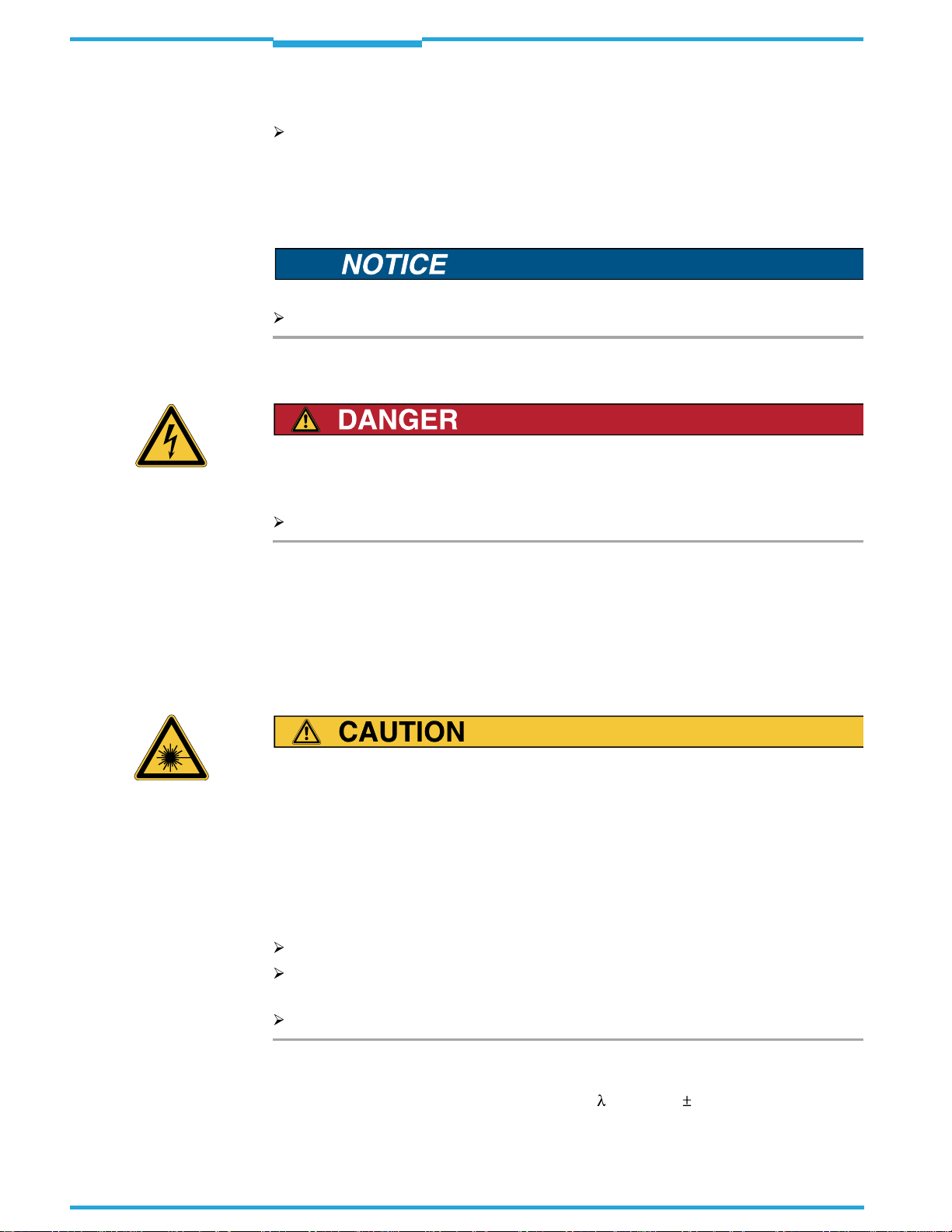
2.3.3 LED radiation
LED radiation!
The illumination of the ICR845-2 op
erates with LEDs of LED class 1.
Under normal and sensible conditions, the accessible radiation of the LEDs is not hazardous. Blinding, impairment of ability to see color, or other irritations, however cannot be excluded.
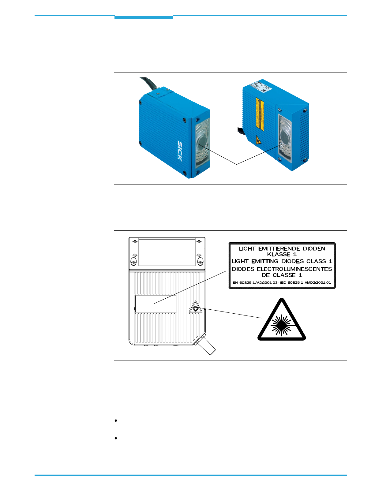
The entire area of the reading window (
Fig.2-1
) acts as a LED outlet aperture.
Caution – use of controlsoradjustments or performanceof proceduresother than those
specified herein may result in hazardous radiation exposure.
Never look directly into the illumination.
Do not open the housing.
(Opening the housing does not deactivate the LEDs by the reading pulse.)
Always observe the latest valid version of laser protection regulations.
10
Radiation power
The illumination LEDs operate at a wavelength of
= 617 nm
15 nm (visible red light)
with a pulse duration of max. 5 ms. The energy in the human eye is < 2.1 J/m2.
SICK AG · Division Auto Ident · Germany · All rights reserved 8012377/0000/2008-01-30
©
Page 11
Operating Instructions
ICR845-2
Safety Information
Chapter
2
Important
The product is classified in LED class 1 in
accordance with EN 60825-1 and IEC 60825-1
(for publication date, see the warning sign on the device).
Maintenance is not required to ensure compliance with LED class 1.
Outlet opening
(entire window area)
Fig. 2-1: Outlet opening of the LED radiation at the ICR845-2
Warning labels
At the ICR845-2, the warning label (
Fig.2-2
) in three languages and the warning symbol are
located on the wide side of the housing.
8012377/0000/2008-01-30
Fig. 2-2: Black-yellow signed warning labels found on the ICR845-2
If the ICR845-2 is installed in a machine/panel with the result that the warning labels are
no longer visible, additional warnings (not included in the scope of delivery) must be provided on the machine beside the emergence aperture of the LED radiation.
Controlling the illumination LEDs
Activation and deactivation of the LEDs when reading is controlled by the reading pulse
(trigger source).
A timer (illumination timeout) automatically
deactivates the LEDs 10 minutes (default
setting) after a continuous reading pulse is initiated in Reading mode with switching input pulse modes "Sensor Input" and "Serial
SICK AG · Division Auto Ident · Germany · All rights reserved
©
Interface". However, it does not end the
11
Page 12

Chapter
2
Safety Information
Operating Instructions
ICR845-2 Image Code Reader
reading interval. In this case, the ICR845-2
iary interface:
"Illumination safety timeout"
The reading interval must be terminated by resetting the trigger signal. The LEDs are
activated again by the next reading pulse.
The illumination timeout can be set in the range of 1 min to 25 h or deactivated.
The illumination LEDs are periodically activated in the operating mode "Percentage
Evaluation" and are always activated in the pulse mode "Free Running" in Reading
mode.
outputs the following message to the auxil-
2.4 Quick stop and quick restart
2.4.1 Switching the ICR845-2 off
Switch off the power supply or remove the ICR845-2 cable plug from the connection
module.
This can result in loss of the following (at the most):
The application-specific paramete
The last reading result
Daily operating data
(operating hours counter, reading interval co
imum duration reading interval, minimum duration reading interval, number of matches with match code 1, number of matches with match code 2, number of No Matches.)
r set, if it was only stored
unt, good read count, no read count, max-
temporarily
in the ICR845-2
2.4.2 Switching the ICR845-2 on again
Switch on the supply voltage or reattach the ICR845-2 cable plug to the connection
module.
The ICR845-2 resumes operation with the
resets the daily operating data.
last permanently stored
parameter set and
2.5 Environmental information
The ICR845-2 is designed to cause minimum im
tain any silicone-based materials on the housing surface and, therefore, does not represent
any problems for paint sprayers in paint shops, for example.
2.5.1 Power requirements
The power requirements are low: The ICR845-2 has a maximum power consumption of typically 13 W. The value is given for devices with disconnected switching outputs.
2.5.2 Disposal after final removal from service
At present SICK AG does not take back device
Dispose of unusable or irreparable devices in
ulations on waste disposal in a manner compatible with the environment.
The ICR845-2 can be separated into recyclable
gory waste (electronic scrap).
See
Chapter 7.5 Disposal, Page104
.
pact on the environment. It does not con-
s which have become unusable or irreparable.
accordance with the respective state reg-
secondary raw materials and special-cate-
12
SICK AG · Division Auto Ident · Germany · All rights reserved 8012377/0000/2008-01-30
©
Page 13

Operating Instructions
ICR845-2
Product description
Chapter
3
3
Product description
This chapter describes the design, the fe
For installation, electrical installation and
tion-specific configuration of the ICR845-2 using the CLV-Setup configuration software,
please read this chapter
3.1 Design of device
The ICR845-2 consists of a image recording system (lense and CMOS matrix sensor with
global shutter) and an electronic unit (image
The image recording system and the electronic unit are located in an industry-compatible
housing. The light exits and enters via a reading window in the housing, which also contains
an arrangement of LEDs for illuminating the reading area.
For an adaptation to on-site space conditions
front reading window and a housing with side
tachment, the reflected light enters through the side reading window at an angle of 90
ferred to the centre-line of the housing.
Depending on the type, various lenses enable
The ICR845-2 is electrically connected by a shielded cable with a D-Sub HD plug and by an
RJ45 socket on the housing. The ICR845-2 meets the enclosure rating IP 65 using an optional adapter frame with the corresponding Ethernet cable or a corresponding cover.
Fig.3-1, Page14
atures and the functions of the ICR845-2.
startup assistance as well as for the applica-
prior
to carrying out any of the tasks.
processing system with integrated decoder).
two housings are available: a housing with
reading window. Via the integrated angle at-
different resolutions and reading ranges.
shows the view of the ICR845-2.
re-
8012377/0000/2008-01-30
SICK AG · Division Auto Ident · Germany · All rights reserved
©
13
Page 14
Chapter
3
Product description
Operating Instructions
ICR845-2 Image Code Reader
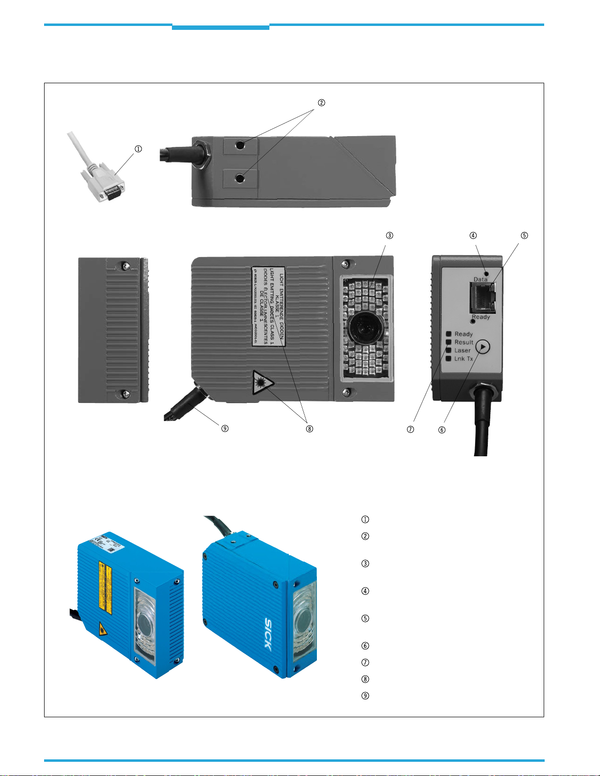
3.1.1 View of device
Side reading window
Fig. 3-1: Design of the ICR845-2
14
©
Front reading window
Key:
D-Sub HD cable plug, 15-pin
Tapped blind hole M5, 8 mm (0.31 in)
deep, for mounting the ICR845-2
Reading window with lens and
illumination LEDs
Tapped hole M3, 5.5 mm (0.22 in) deep,
for mounting the IP 65 adapter frame
RJ45 10baseT socket for
Ethernet connection, with LEDs
Function key
LEDs (status indicators)
Warning labels
Connection cable
SICK AG · Division Auto Ident · Germany · All rights reserved 8012377/0000/2008-01-30
Page 15

Operating Instructions
ICR845-2
Product description
Chapter
3
3.1.2 Scope of delivery
Delivery of the ICR845-2 includes the following components:
No. Component Comment
1 ICR845-2 Image Code Reader Type depends on version, see
1 Notes on device with electrical connection dia-
gram and quick start as primary information
1 CD-ROM "Manuals & Software Bar Code Scan-
ners"
ICR845-2 Operating Inst
form, in German and/or English
Tab. 3-1: ICR845-2 delivery
ructions in printed
Included in the device packing of the
ICR845-2
Included in the device packing of the
ICR845-2
Optional, depending on the number of
issues explicitly ordered upon purchase
Tab. 3-2
An overview of in-stock installation accessories, connection modules, sensors for reading
pulses, incremental encoder, cables and plug-in connectors is available in
Chapter 10.8 Or-
dering information for ICR845-2 and accessories, Page 164.
3.1.3 Contents of the CD-ROM (Nr. 2029112)
Important
Important
CLV-Setup
: Configuration software for standard PC (WindowsTM) with integrated
online help system CLV-Setup Help (HTML files)
CLV-Connect
: Presentation software for standard PC (WindowsTM) for displaying connec-
tion diagrams (HTML files)
ICR845-2 operating instructions
publications of other SICK devices (c
Adobe Reader
: Freely available PC software for displaying PDF files
All current versions of publications and prog
at
www.sick.com
.
: PDF version in German and English as well as further
onnection modules, bar code scanners)
rams on the CD-ROM can also be downloaded
3.1.4 Device versions
The ICR845-2 is available in the following versions:
Type (red light) Order no. Version Reading window
ICR845-2C0020 1043740 Mid Range On front
ICR845-2C1020 1043739 On side
Tab. 3-2: Versions of the ICR845-2
Other versions on request.
8012377/0000/2008-01-30
SICK AG · Division Auto Ident · Germany · All rights reserved
©
15
Page 16

Chapter
3
Product description
3.2 System requirements
General system requirements are devired from the technical data of the ICR845-2 (see
Chapter 9 Technical data, Page121
The requirements and conditions for
configuration
are summarised in the respective chapters.
3.3 Product features and functions (overview)
Feature Characteristic
High-performance reader
Safety and user-friendly features
Easy configuration
Operating modes
Reading pulse
2D code/1D code evaluation
Data processing
Data communication
CMOS matrix sensor of newest technology (WVGA resolution)
Fixed focus
Front reading window or side reading window
Resolution, reading range (DOF) and field of view depending on type (Mid Range)
60 Hz Image recording rate at full field of view
Function to adapt to the code marking quality/object velocity
Variable active evaluation range of the matr
Robust, compact metal housing, max. IP 65, CE certification
LED class 1, illumination LEDs switches off if reading interval is active for too long
Automatic self-test on startup. Can also be triggered at any time
Diagnosis tools for installing and monitoring the system
Variable output of reading diagnosis data in the read result
Operating data query, and error messages on request
Test string function for sign
Future proof thanks to firmware update via data interface (flash PROM)
Low power consumption
Extended power voltage range
Configuration (online/offline) via CLV-Setup configuration software with integrated Assistant (Connection Assistant) and help system.
Displaying the image memory content via the ImageFTP program.
Configuration alternatively with simple command strings, also for use with special devices
Function key for starting functions without using CLV-Setup
Four status LEDs
Beeper to confirm device functions or
Reading mode
Percentage evaluation - for assessing the quality of the reads (2D codes only)
Special functions for system installation
External reading pulse, via switching input(s) or serial data interface
Free running with timeout
Data Matrix ECC 200/all standard bar code types
Max. 50 codes per image/reading pulse (max. 4,000 characters)
Separation of identical codes of the same code type
Code comparison (max. 2 matchcodes), can also be used as filter as sort criterion for the
reading result
Manipulation of the data output string via filter or format mask
Sort sequences: code position, FIFO, LIFO, code length list, ROI sequence
Host interface: variable output format for reading result, communication can be routed via
the CAN or Ethernet interface
Auxiliary interface (auxiliary data interface): fixed output format, with special diagnosis
functions, communication can be routed via the Ethernet interface
ICR845-2 Image Code Reader
).
Installation, Electrical installation
ix sensor, thereby higher image recording rate
aling readiness for operation
operating steps (can be switches off)
Operating Instructions
and
Startup and
Tab. 3-3: Overview of the product features and functions
16
SICK AG · Division Auto Ident · Germany · All rights reserved 8012377/0000/2008-01-30
©
Page 17
Operating Instructions
ICR845-2
Feature Characteristic
Electrical interfaces
Connection technology (design)
Tab. 3-3: Overview of the product features and functions (contd.)
Product description
Serial host interface (RS 232 or RS 422/485), variable data transfer rate and protocol
Serial auxiliary interface (RS 232), with fi
Ethernet interface with TCP/IP and FTP
CAN interface for integration in the SICK CAN scanner network or a CANopen network
2 digital switching inputs for external reading pulse and special function (e.g. encoder in-
crement)
2 digital switching outputs for signaling defined events in reading mode as well as for
triggering or direct powering an external field illumination
Data and switching interfaces as well as power supply:
– Cable with 15-pinD-Sub HDplug
– Ethernet: 8-pinRJ45 10 baseTsocket on device
CDB620 or CDM420 Connection Module for connection to host (stand-alone) and for inte-
gration in SICK CAN scanner network
CMF400 Connection Module Fieldbus in the
to DeviceNet or PROFIBUS-DP
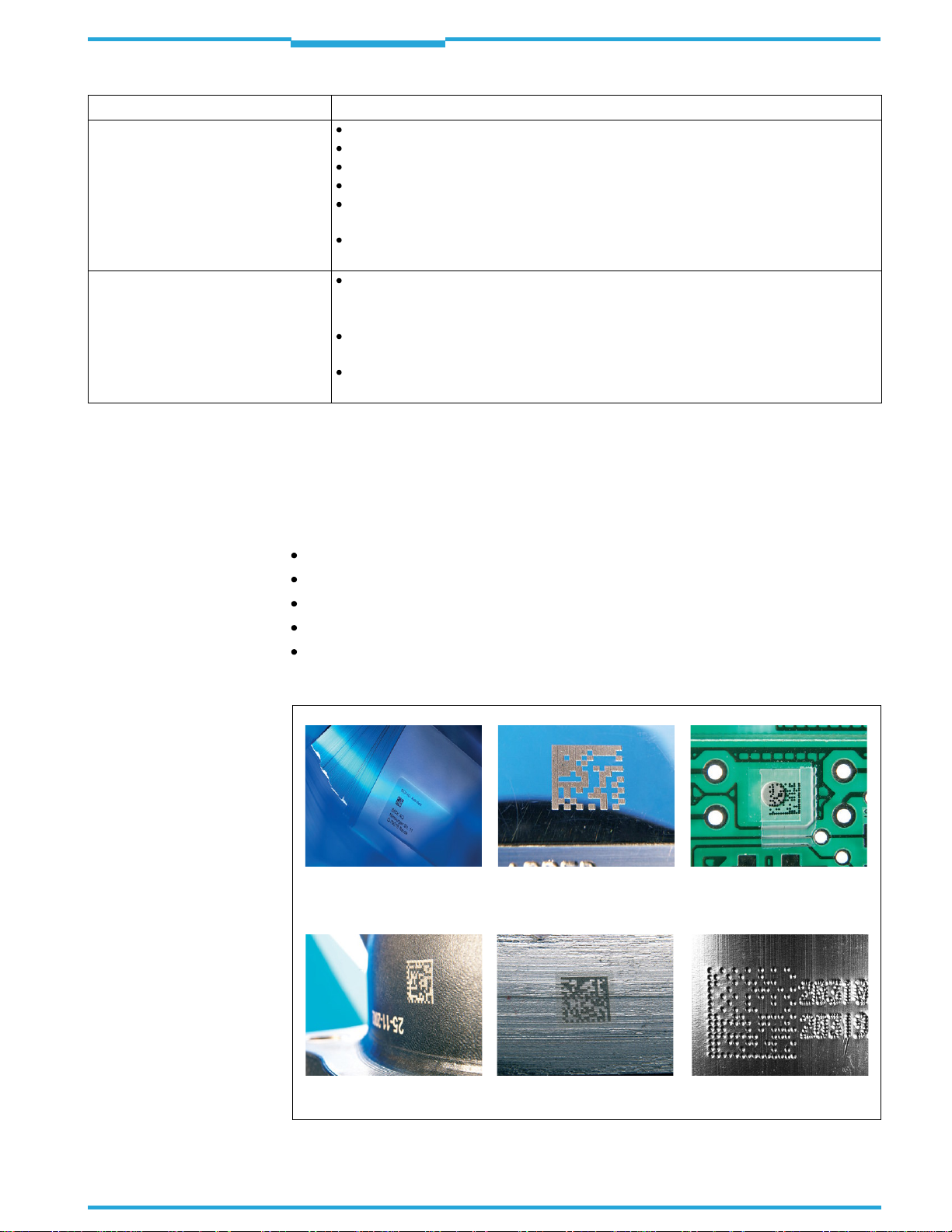
3.3.1 Field of applications
Chapter
xed data transfer rate and fixed protocol
CDM420 Connection Module for connection
3
The ICR845-2 can read 2D codes, which either have been added to the object using labels
or have been directly marked onto the object surface (DPM) with one of the following methods:
Inkjet printing
Nd-YAG laser
CO2 laser
Laser marking on metal
Dot peening on metal
Fig.3-2
shows some samples for various marking methods.
Inkjet on paper
Laser on shiny surface Inkjet on plastic
8012377/0000/2008-01-30
Laser on curved surfaces Laser on cast iron Needle stamping on metal
Fig. 3-2: ICR845-2: Direct marking methods for 2D codes
SICK AG · Division Auto Ident · Germany · All rights reserved
©
17
Page 18
Chapter
3
Photoelectric switch
Reading pulse
Signal
Path increment
Teach-in match code 1
End of reading interval
Product description
Operating Instructions
ICR845-2 Image Code Reader
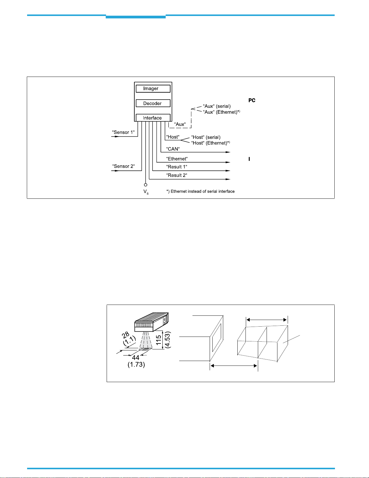
3.4 Method of operation
The ICR845-2 consists of a image recording system (lense and CMOS matrix sensor with
global shutter) and an electronic unit (image processing system with integrated decoder). It
reads and decodes 1D codes (bar codes) and 2D codes.
Configuration
Diagnosis etc.
Further processing of
reading result
e.g. CAN scanner network
mage output to PC
Status indicator
e.g. Good Read
e.g. No Read
Fig. 3-3: Block diagram: functions of the ICR845-2
3.4.1 Image recording
For image recording the ICR845-2 takes a rectangular image of the area to be read. To do
so, an illumination lights the area to be read
illumination field (pulsed) with a flash freque
When starting a reading cycle, the ICR845-2 sw
sensor the ICR845-2 absorbs repeatedly the light reflected from the field of view (
through the lens as gray values. The recorded images are stored in an electronic image buffer memory. To prevent distorted images while the image are being recorded, the shutter
speed must be adapted to the velocity of the objects carrying the codes. The velocity permitted depends on the cell size, the contrast of the code layout and the flash duration.
All dimension in mm (in)
ICR845-2
. The LEDs of the illumination generate a red
ncy and duration calculated by the ICR845-2.
itches on the illumination. With the matrix
Fig.3-4
Depth of field
Field of
view
Reading distance
)
18
Fig. 3-4: Field of view of the ICR845-2 in the focus position (Mid Range)
The field of view, which is mapped in sharp focus by the ICR845-2 on its matrix sensor, depends on the reading distance and, depending on
range (DOF).
Chapter 9.3 Specification diagram, Page 124
the resolution, must be within the reading
shows the available field of
view. The image recording rate is 60 Hz at full matrix sensor ulitisation. If the appropriate
configuration settings are made to reduce the matrix sensor area (image geometry) used
for the evaluation, this increases the potential image recording rate. The ICR845-2 automat-
SICK AG · Division Auto Ident · Germany · All rights reserved 8012377/0000/2008-01-30
©
Page 19

Operating Instructions
ICR845-2
Product description
Chapter
3
ically adjusts the flash frequency and duration. With a maximum of two working areas, a
maximum of just two separate strips in the im
age field can be evaluated. To read the codes
successfully when the active field of view is reduced, the objects must be routed exactly and
the codes must be fixed in the same location.
On request, the ICR845-2 outputs the image bu
ffer memory content as binary or grey scale
bitmap via the Ethernet interface. The images can be displayed by the Image FTP program.
3.4.2 Decoding
As codes are detected in the image data, th
the code(s) contents. At the end of the read
information via its host interface
to a host/PC for further processing.
e ICR845-2’s decodingalgorithmsdetermine
ing cycle the ICR845-2 outputs the code data
The ICR845-2 is equipped with four decoders:
The decoder for omni-directional reading of 2D codes
The tried-and-tested standard decoder of the CLV series for 1D codes (bar codes)
The SMART decoder (SICK Modular Advanced Recognition Technology) for decoding
1D codes on following conditions:
– smallaspect ratio (ratio of the codeheight to thecodelength)
– dirtyordamaged printed code
– bar codes that aretilted excessively(azimuth angle)
The 360°-decoder for omni-directional reading of 1D codes
The ICR845-2 derives useful diagnosis data from the reading process and transfers it to the
host. It also records operating data that can be requested at any time. The reading quality
of 2D codes can be checked in the "Percentage Evaluation" operating mode.
3.4.3 Reading triggering and indicating of result status
To start the reading process when an object is located in the field of view, the ICR845-2 re-
quires a suitable trigger. This opens a time window ("reading interval") in the ICR845-2 for
the reading procedure. In the default setting, th
is trigger is supplied by an external reading
pulse sensor. Alternative trigger sources include Free Running mode or a command sent via
the host interface.
8012377/0000/2008-01-30
The current operating status is indicated by four LEDs. A beeper indicates the status of the
reading result. In the default setting, the
"Good Read" function is selected for this.
If the trigger is supplied externally by a sensor, the "Sensor 1" switching input signals the
start of the reading procedure to the ICR845-2. The "Sensor 2" switching input is used to
signal alternatively the end of reading procedure or to enter a path increment. It can also be
used e.g. to teach in a match code.
The "Result 1" and "Result 2" switching outputs can be assigned various functions and trigger external devices, such as a PLC. Using the "Result 1" output, an external illumination can
additionally be triggered
The ICR845-2 is configured via the serial auxili
or directly powered (max. 100 mA) by the ICR845-2.
ary interface/host interface with the CLV-Setup configuration software or with command strings. Alternatively, the Ethernet interface is
available for both types of operation.
The ICR845-2 outputs system and error messages as error codes, which can be requested
from the error memory using command strings.
SICK AG · Division Auto Ident · Germany · All rights reserved
©
19
Page 20

Chapter
3
Product description
Operating Instructions
ICR845-2 Image Code Reader
3.5 Indicators and control elements
3.5.1 Control elements
The ICR845-2 is configured application-specific
ally using the CLV-Setup configuration software. The software runs on a PC which must be connected to one of the two data interfaces
(auxiliary interface: serial RS 232 or Ethernet, host interface: serial RS 232/RS 422/485 or
Ethernet) of the ICR845-2.
Chapter 10.4 Installation and operating instructions for the CLV-Setup configuration software, Page136
plains how to use it. Configuration is explained in
describes the procedure for installing the PC software "CLV-Setup" and ex-
Chapter 6 Startup and configuration,
Page47.
As an alternative to the CLV-Setup configur
ation software, command strings are available
upon which the user interface of the CLV-Setup configuration software is based (see also
Chapter 10.5 Configuring the ICR845-2 with command strings, Page146.
Start-up as well as diagnosis in case of an
error can be carried out via the CLV-Setup configuration software. Some function can also be started using the function key. The ICR8452 operates fully automated in normal operation.
3.5.2 Function key on the housing of ICR845-2
With the function key you can start a pre-configurated function without using the CLV-Setup
configuration software. At the moment, only the reading interval can be started. On the device, the foil key is located nearby the LEDs (
Fig.3-1, Page14
).
In the default setting the function key is active. The key can be deactivated with the CLVSetup configuration software.
Chapter 6.5 Using the function key, Page 68
describes how to use the key.
3.5.3 Function of the LEDs
General LEDs
Four LEDs indicate the operating status, activity of the illumination LEDs, the reading result
status and data transfer on the serial host interface.
Fig. 3-5: LEDs
The LEDs are located on the rear of the device toward the bottom (
Table 3-4
shows the meaning of the LEDs in the different operating modes/functions.
Fig.3-1, Page14
).
20
SICK AG · Division Auto Ident · Germany · All rights reserved 8012377/0000/2008-01-30
©
Page 21

Operating Instructions
ICR845-2
Product description
LED Colour Funktion
Ready
Result
Laser
Lnk Tx
Tab. 3-4: Meaning of the general LEDs
Orange
Green
Green
Green
Green
Lights up shortly after power-up if the self-test was successful
Lights up constantly in Reading mode
Extinguishes with new operating mode/function
Lights up shortly after power-up if the self-test was successful
Lights up after a good read (default setting: Good Read).
The LED is connected to the "Result 2" switching output. It indicates the selected result status for the set pulse duration of the output.
Lights up shortly after power-up if the self-test was successful
Lights up when the illumination LEDs are active
(The illumination LEDs are activated/deactivated by reading pulse).
Lights up constantly in the pulse mode Free Running, as the illumination
LEDs are always active.
Flickers while the ICR845-2 transfers data to the host on the serial host
interface
Chapter
3
LEDs of the Ethernet interface
Two LEDs, integrated in the RJ45 socket 10baseT (
the Ethernet connection.
LED Colour Function
Ready
Data
Tab. 3-5: Meaning of the LEDs of the Ethernet interface
Green
Yellow
Table 3-5
lists the meaning of the LEDs.
Indicates the physical Ethernet connection
Lights up when the ICR845-2 receives or sends addressed
data via Ethernet
Fig.3-1, Page 14
), indicate the status of
8012377/0000/2008-01-30
SICK AG · Division Auto Ident · Germany · All rights reserved
©
21
Page 22

Chapter
3
Product description
Operating Instructions
ICR845-2 Image Code Reader
3.5.4 Function of the beeper
The beeper uses different tone sequences and lengths (
Table 3-6
) to signal whether functions have been executed successfully and whether any malfunctions have occurred. For information on troubleshooting, see
Chapter 8.5 Troubleshooting, Page109.
In the default setting, the beeper is activated and indicates the result status "Good Read"
for the Reading mode. It is assumed in these Operating Instructions, that the beeper is operated with the default setting in Reading mode.
Tone sequence Function
Power-up:
Beep
Beep Beep
Beep
Beep Beep Beep
Beep
High beep
Tab. 3-6: Beeper function
Signals that the self-test after power-up was successful
Confirms that the device has assumed Reading mode
Reading mode:
Confirms a successful read (good read; default setting) and the reading result output
Signals that the illumination LEDs have been deactivated after the illumination timeout of 10 min (def
Reading mode. The reading interval is still active.
Application of function key:
Confirms the start of the reading interval
Confirms a successful read or the end of the reading interval
ault setting) was exceeded in
Tip
The behavior of the beeper in
ration software.
Reading mode
can be changed with the CLV-Setup configu-
22
SICK AG · Division Auto Ident · Germany · All rights reserved 8012377/0000/2008-01-30
©
Page 23

Operating Instructions
ICR845-2
Installation
Chapter
4
4
Installation
Important Do not open the housing of the ICR845-2.
4.1 Overview of installation sequence
This chapter describes the installation sequ
ponents.
The typical installation sequences are listed below:
Selecting the installation location for the ICR845-2
Aligning the ICR845-2 to the code and installing the device
Installing the connection module CDB620 or CDM420
Connecting the ICR845-2 to connection module CDB620 or CDM420
Adjusting the ICR845-2 (reading distance)
Installing the reading pulse sensor for reading pulse triggering
shall not apply.
ences for the ICR845-2
If the device is opened, the SICK AG warranty
and the external com-
4.2 Installation preparations
The following general requirements should be observed for installation:
Typical space requirement: application-specific and type-dependent (reading range,
orientation of reading window)
Unobstructed view of the objects for the ICR845-2
Stable installation holder with sufficient load capacity and dimensions suited to the
ICR845-2 (see
Shock absorbent and vibration free attachment
Chapter 9.2 ICR845-2 dimens
ional drawing, Page 123
)
The following tools and resources are required for installation:
Two screws M5 for installing the SICK mounting bracket no.2025491/ no. 2039465 or
the quick release clamp no. 2042484 to the base.
The screw length depends on the wall thickness of the base.
Tool
Goniometer
4.2.1 Components to be installed
The following components have to be placed ready for installation:
ICR845-2 Image Code Reader
4.2.2 Accessories
The following accessories are not included in the delivery of the ICR845-2. They have to be
ordered separately and placed ready for installation:
Mounting device, see next chapter
Connection module CDB620 or CDM420
Reading pulse sensor for external reading pulse triggering, e.g. photoelectric reflex
switch(es)/photoelectric proximity switch
8012377/0000/2008-01-30
SICK AG · Division Auto Ident · Germany · All rights reserved
©
23
Page 24
Chapter
4
Installation
Operating Instructions
ICR845-2 Image Code Reader
4.2.3 Mounting device
The ICR845-2 is fixed using two blind hole taps (M5) that are located on the narrow side of
the device (see
Chapter 9.2 ICR845-2 dimensional drawing, Page 123
).
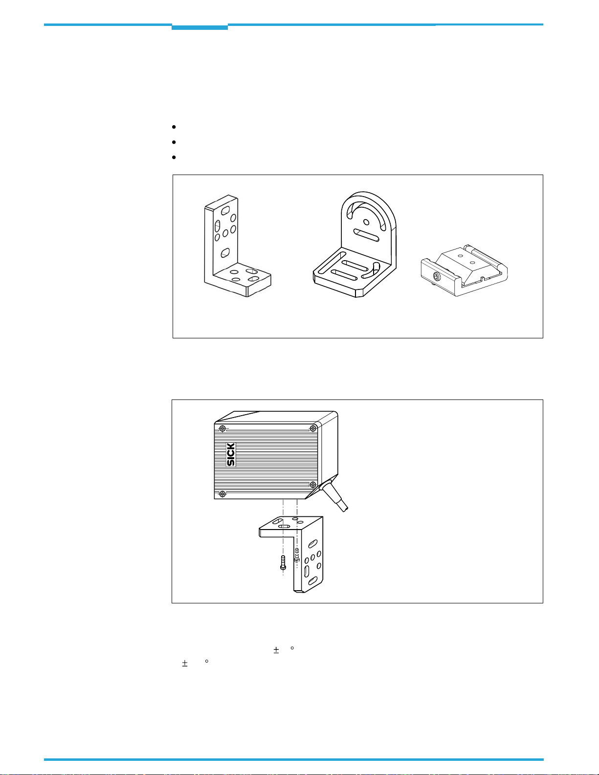
The ICR845-2 can be mounted using the following SICK holders:
Mounting bracket no. 2025491
Mounting bracket no. 2039465
Quick release clamp no. 2042484
Mounting bracket
no.2025491
Fig. 4-1: Installation accessories
Mounting bracket
no.2039465
Quick release clamp
no.2042484
The construction of the mounting brackets supports various mounting options and the alignment of the ICR845-2 in two axis.
Fig.4-2
shows a mounting option.
24
Fig. 4-2: Example: Fixing the ICR845-
For the fine adjustment of the ICR845-2, th
2 with the mounting bracket no. 2025491
e slots in the mounting bracket no.2025491 allow a turning freedom of 15 and in the mounting bracket no. 2039465 a turning freedom
of
180
.
The dimensions of the mounting brackets
and the quick release clamp are shown in
Chapter 10.9 Dimensional drawings accessories, Page 169.
SICK AG · Division Auto Ident · Germany · All rights reserved 8012377/0000/2008-01-30
©
Page 25
Operating Instructions
ICR845-2
Installation
Chapter
Alternatively, the user can provide a holder.
The holder must meet the following requirements:
Stable mounting device.
– Adjustablealignment of the ICR845-2 in the x and yaxis
– Themounting device must be ableto bearthe weight of theICR845-2 includingits
connection cable (ca. 900 g (approx. 31.75 oz)) without vibrating.
Two screws M5 to fix the ICR845-2.
– Thescrewlength depends on the wall thicknessof the mountingdevice.
– Themaximum threadreachin theICR845-2is8 mm
(0.32 in) from the housing sur-
face.
4.3 Installation location
The following aspects are relevant for the selection of the installation location:
Allocation of the field of view for the code
Reading distance to the code/field of view dimensions
Angle alignment of the ICR845-2
Avoiding surface reflections
Counting direction of the code position (position of the code in the longitudinal direction
of the field of view)
4
Furthermore, the distance between the ICR845-2 and the host computer and the distance
to the connection module has to be taken into account (see
tion preparations, Page 31
CDM420, Page29
).
and
Chapter 4.5.1 Installing connection module CDB620 or
Chapter 5.2 Electrical installa-
4.3.1 Allocation of the field of view to the code
The main allocation of the field of view to the code on the object (
version of the ICR845-2 (front or side reading window).
ICR845-2 with front reading window
Fig. 4-3: ICR845-2: Allocation of the field of view to the code
ICR845-2 with side reading window
Fig.4-3
) depends on the
8012377/0000/2008-01-30
4.3.2 Reading distance to the code/field of view dimensions
The distance between the reading window of the ICR845-2 and the code is determined by
the fixed focus position of the ICR845-2 and the
sired cell size/module width. The distance may
Chapter 9.3 Specification diagram, Page 124
Fig.4-4
©
shows the exact definition of the reading distance from the reading window.
SICK AG · Division Auto Ident · Germany · All rights reserved
resolution-specific dept
h of field for the de-
not exceed the total technical limits (see
).
25
Page 26
Chapter
4
Installation
Operating Instructions
ICR845-2 Image Code Reader
ICR845-2 with front reading window
All dimensions in mm (16 mm = 0.63 in)
Fig. 4-4: Definition of the reading distance and the field of view
Type Version Focus position Z Length X Width Y
ICR845-2C0020 Mid Range 115 mm (4.53 in) 44 mm (1.73 in) 28 mm (1.1 in)
ICR845-2C1020
Tab. 4-1: Reading distance and field
of view dimensions (type-depended)
ICR845-2 with side reading window
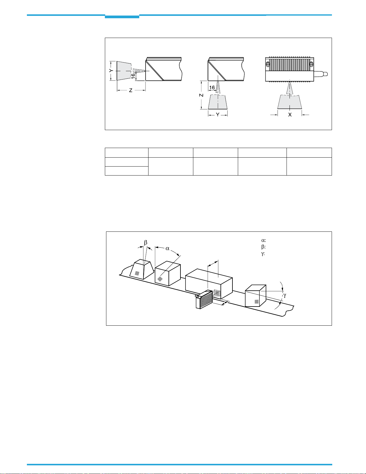
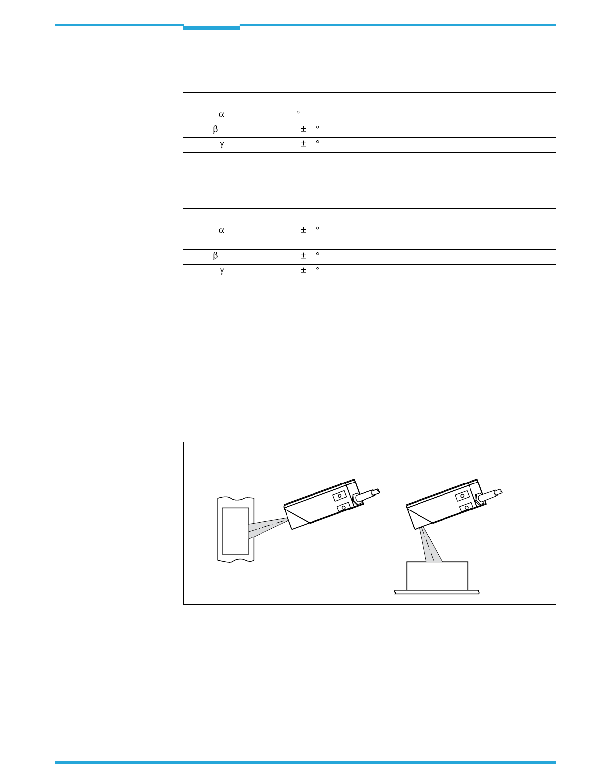
4.3.3 Angle alignment of the ICR845-2
The ICR845-2 is optimally aligned if the code is
code positions that can occur between the field
the room have to be taken into account (
in the centre of the field of view. Possible
of view and the code in all three levels in
and
Fig.4-5
Table 4-3
).
Azimuth angle (tilt)
Reading
range
Reading
distance
Fig. 4-5: Reading angle that can occurs between the field of view and the code
Inclination angle (pitch)
Rotation angle (skew)
26
SICK AG · Division Auto Ident · Germany · All rights reserved 8012377/0000/2008-01-30
©
Page 27
Operating Instructions
ICR845-2
Installation
Chapter
4
Important
The following applies for bar codes and 2D co
omni-directional decoder:
Angle Limit value
Azimuth
Incline
Rotation
Tab. 4-2: Permissible reading angle between the field of view and the bar code/2D code when
The following applies for bar codes when reading with standard/SMART decoder:
Angle Limit value
Azimuth
Incline
Rotation
Tab. 4-3: Permissible reading angles between the
The length of readable bar code is reduced with
of the distance-dependent dimensions of the field of view (see examples in
Page122
(tilt) 360
(pitch) Max. 45 (depending on the cell size and symbol size)
(skew) Max. 45 (depending on the cell size and symbol size)
reading with omni-directional decoder
(Tilt) Max.
(Pitch) Max. 45 (depending on the module width)
(Skew) Max. 45 (depending on the module width)
standard/SMART decoder
).
45
(lengthwise of the field of view and in focus position 100 mm
(3.94 in) for module width 0.2 to 0.5 mm (7.9 to 19.7 mil))
des (Data Matrix ECC200) when reading with
field of view and bar code when reading with
respect to the decodable length as a result
Table 9-2,
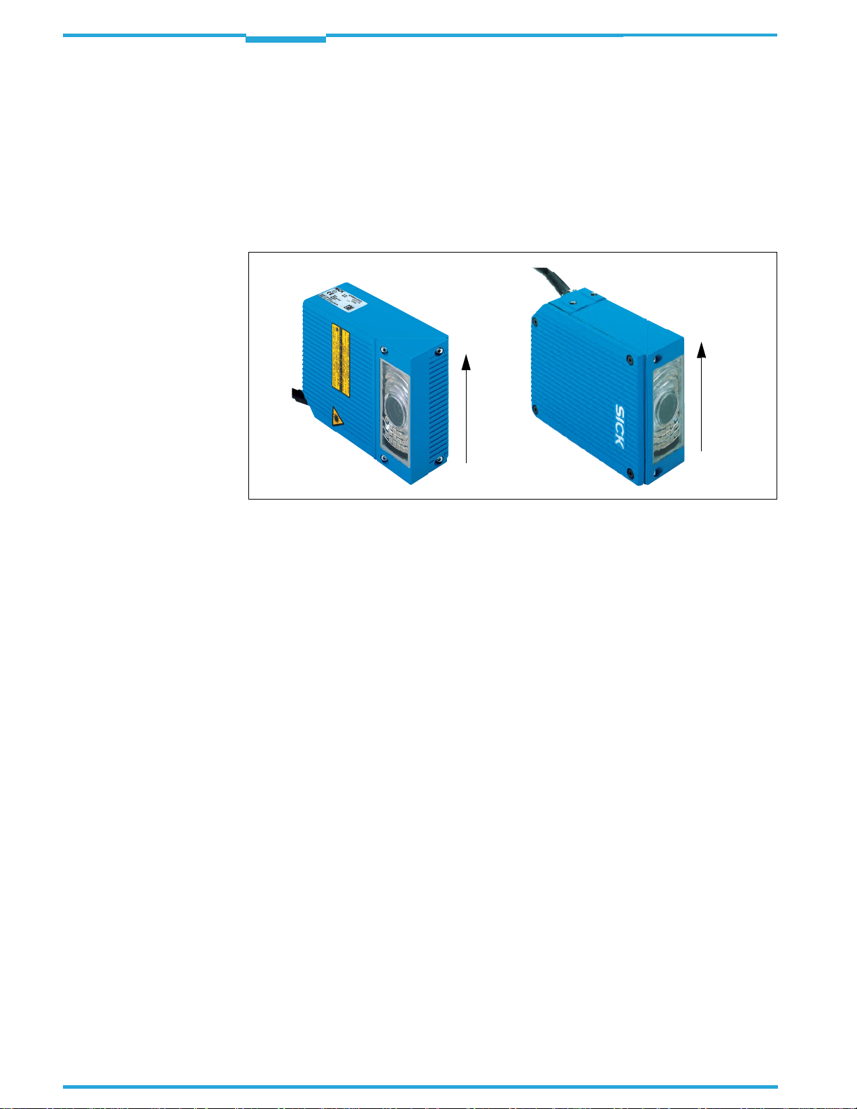
4.3.4 Selecting the rotation angle (skew) to avoid surface reflections
If the light of the red illumination field vertically meets the surface of the code, this can re-
sult in disruptive reflections when the bounced back light is received. To prevent this effect,
the ICR845-2 must be installed in such a way that the illumination light emitted is tilted
down relative to the plumb line.
ICR845-2 with front reading window
20°
(Top view)
Fig. 4-6: Avoiding surface reflection: Angle between emitting light and code (tilted away from the
plumb line)
4.3.5 Counting direction of code position (position of the code in the longitudinal
direction of the field of view)
ICR845-2 with side reading window
20°
(Side view)
Explanation
8012377/0000/2008-01-30
The ICR845-2 can record and decode several codes with each image. In doing so, it determines the local reading diagnosis data for each code in the image buffer memory.
Fig.4-7
corresponds to the longitudinal direction of the field of view).
©
shows the count direction of the code position CP along the reading window (this
SICK AG · Division Auto Ident · Germany · All rights reserved
27
Page 28
Chapter
4
Installation
Operating Instructions
ICR845-2 Image Code Reader
The determination of the code position enables identical codes (code type, code length and
data contents) to be separated and the code da
ta to be assigned to their position on the
object.
Important
For
2D codes
age buffer memory. It outputs its corner points
, the ICR845-2 determines the spatial position of the finder patterns in the im-
in the shape of two-dimensional coordinates
in the reading result of the auxiliary interface as the "PT" reading diagnosis data (see
Chapter 1. Output of reading result on the auxiliary interface: 2D code (Data Matrix
ECC200), Page76.
100 %
CP
0 %
Fig. 4-7: Count direction of the code position CP for bar codes along the reading window
For
bar codes
, the ICR845-2 determines the position of the first dark line of the start char-
100 %
CP
0 %
acter in the image buffer memory. It outputs the value in the reading result of the auxiliary
interface as reading diagnosis data "CP" (see
auxiliary interface: Bar code, Page78
).
When the ICR845-2 (Mid Range) is in th
Chapter 2. Output of reading result on the
e focus position (reading distance 115 mm
((4.53 in)), 1% of the CP is approx. 0.44 mm (0.017 in) lengthwise of the field of view.
In the default setting, the ICR845-2 does not output the values "PT" or "CP" in the reading
result of the host interface. If this is required to evaluate the result in the host, the values
can be included in the "reading data" block of the output string using the CLV-Setup configuration software.
28
SICK AG · Division Auto Ident · Germany · All rights reserved 8012377/0000/2008-01-30
©
Page 29

Operating Instructions
ICR845-2
Installation
4.4 Installing and adjusting the ICR845-2
4.4.1 Installing the ICR845-2
Damage to the device!
The maximum thread reach of the two blind hole taps M5 is 8 mm (0.32 in).
Longer screws will damage the device.
Use screws with the correct length.
Chapter
4
1. Prepare the holder and the base for the installation of the ICR845-2, see
Accessories, Page23.
2. Screw the M5 screws through the holder into the blind hole taps of the ICR845-2.
3. Tighten the screws slightly, so that the ICR845-2 can to be varied in the x and y axes
for adjusting.
4. Place the object containing the 2D code within the field of view of the ICR845-2 in the
position at which it is to be read.
5. Align the ICR845-2 in combination with the holder to the code using a goniometer in
such a way that:
– ThewidesideoftheICR845-2 withthewarninglabelsisadjustedunderanangleof
approx. 20
– Thefront readingwindowis is adjustedunder anangle of approx20
surface, when using a front reading window.
– Readingdistance(focusposition)fromreadingwindow:
ICR840-2C (Mid Range): 115 mm (4.53 in)
See also
Page 25
– All of the possible readingangles must be taken into consideration, see
4.3.3 Angle alignment of
– If relevanttotheevaluation,payattentiontothecount directionof the codeposition
if applicable (see Chapter 4.3.5 Counting direction of code position (position of the
code in the longitudinal direction of the field of view), Page 27
6. Mark the holder of the ICR845-2 on the base, drill the required holes and install the
holder with the ICR845-2 on the base.
7. Adjust the ICR845-2 exactly, see
to the code surface, when using a side reading window.
Chapter 4.3.2 Reading distance to the code/field of view dimensions,
the ICR845-2, Page 26
Chapter 6.12 Adjusting the ICR845-2, Page 93
.
Chapter 4.2.2
to the code
Chapter
).
.
Important
8012377/0000/2008-01-30
4.5 Installing external components
4.5.1 Installing connection module CDB620 or CDM420
Depending on the application, you can install either connection module CDB620 or
CDM420. The installation process is the same for both modules .
The connection module must not be located further than 10 m (32.8 ft) from the ICR845-2,
since the CLV-Setup configuration software on
of the ICR845-2 via this module (RS 232
1. Install the connection module close to the ICR845-2.
2. Install the connection module in such a way that the opened device can be accessed
at any time.
SICK AG · Division Auto Ident · Germany · All rights reserved
©
the PC accesses the serial auxiliary interface
, 9,600 bd, internal 9-pin D-Sub plug).
29
Page 30
Chapter
4
Installation
Operating Instructions
ICR845-2 Image Code Reader
For detailed information about installation and electrical installation, see the "
nection Module" Operating Instructions (no.8012119) or "
CDM420 Connection Module"
Operating Instructions (no.8010004).
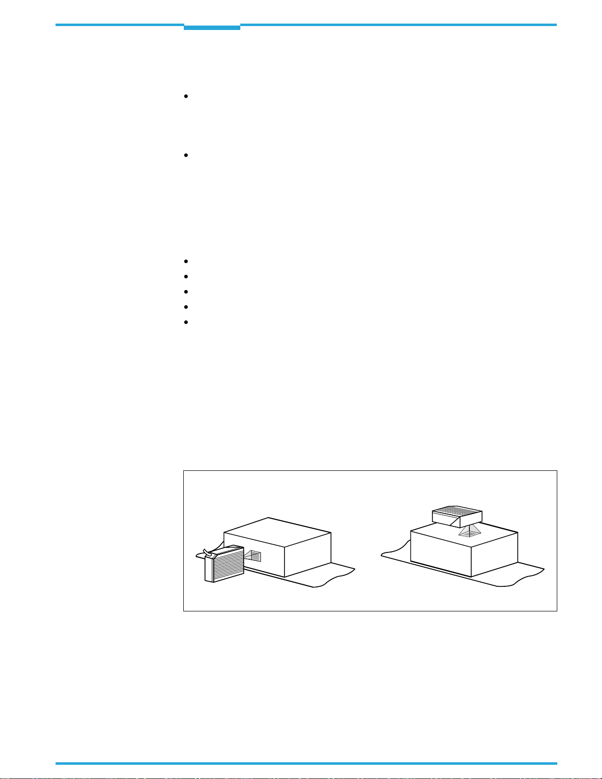
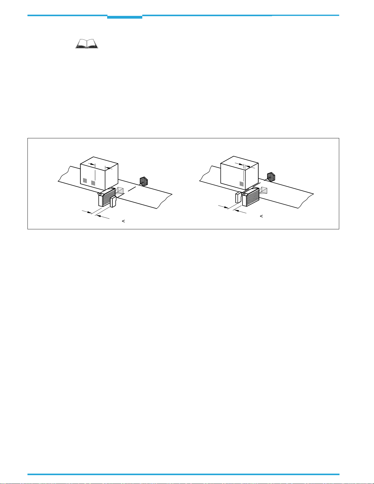
4.5.2 Installing the external reading pulse sensor
If the ICR845-2 is triggered by an external re
ading pulse sensor (e.g. photoelectric reflex
switch), the sensor has to be installed close to the ICR845-2.
Fig.4-8
shows two examples of where a photoelectric reflex switch can be installed. This depends on the distance a from the code to the front of the object. Depending on the application, you may need to attach the sensor in su
ch a way that codes on objects of different
sizes can be read completely during the reading interval.
Code in the middle or at the end of the object Code at the beginning of the object
a
b
b a !
a
b
b a !
CDB620 Con-
Fig. 4-8: Installation example for the external reading pulse sensor
4.5.3 Installing the incremental encoder
If identical codes (code type, code content) have to been separated or if an track-contolled
delay of the external reading trigger is requir
installed, e.g. no. 2022714. The increment pulses must originate from the area of the conveyor belt which the ICR845-2 is reading.
1. Install the incremental encoder near to the ICR845-2, best against the direction of the
conveyor system in front of ICR845-2.
2. Ensure that the incremental encoder has direct and fixed contact with the drive system
and that the friction wheel rotates without slipping.
4.6 Removing the device
Removal of the ICR845-2 is described in
For the environmental friendly diposal after decommissioning see
Page104.
ed, a suitable incremental encoder has to be
Chapter 7.4.1 Removing the ICR845-2, Page 103
.
Chapter 7.5 Disposal,
30
SICK AG · Division Auto Ident · Germany · All rights reserved 8012377/0000/2008-01-30
©
Page 31

Operating Instructions
ICR845-2
Electrical installation
Chapter
5
5
Electrical installation
5.1 Overview of the installation sequence
Important
Electrical installation should only be carried out by qualified staff.
CDB620/CDM420
24 V DC
AUX
Configuration
RS 232
Cable no. 2014054
Ethernet
Cable no. 6026084 (crossover)
Configuration/Image transfer
PC/Laptop
Configuration
Diagnosis
Image visualisation
RS 232 cable
alternatively to Ethernet cable if no image
transfer is required
Fig. 5-1: Block diagram for startup and configuration
The following list provides an overview of a typical installation sequence:
Connecting the ICR845-2 to connection module CDB620 or CDM420
Wiring the data and function interfaces of the ICR845-2 in the connection module
Connecting the Ethernet interface on the ICR845-2 to the PC for image output and con-
figuration (recommended).
– Alternativelywithoutimageoutput:ConnectthePCtotheserial auxiliaryinterfacein
the connection module
Optional: Connecting the external illumination to the connection module
Connecting the power supply to the connection module
Once electrical installation has been completed, the ICR845-2 is started up and configured
(see
Chapter 6 Startup and configuration, Page47
).
5.2 Electrical installation preparations
The following general requirements should be observed for electrical installation:
Supply voltage 15 to 30 V DC (functional extra-low voltage in accordance with IEC3644-41 (VDE 0100 Part 410)), power output at least
by the customer.
Connecting the ICR845-2:
– Via connection module CDB620 or CDM420
– or–
– If wiringwithout a SICKconnection moduleuse the cableno. 6010137 with 15-pin
D-Sub HD plug and open end to connect the ICR845-2.
15 W,
provided e.g. via power pack
8012377/0000/2008-01-30
SICK AG · Division Auto Ident · Germany · All rights reserved
©
31
Page 32

Chapter
5
Electrical installation
Operating Instructions
ICR845-2 Image Code Reader
– If furthermodulesareused in combinationwith the connection modules CDB620/
CDM420 the following supply voltages are required for the ICR845-2:
Connection
module
CDB620-001
CDB620-101
CDB620-201
CDM420-0001 – – 15 to30 VDCV
Tab. 5-1: Required supply voltage if using further modules in combination with the connection
module CDB620/CDM420
Additional
module
– – 15 to30 VDC
CMC600 Connection Module Cloning 15 to 30 V DC/ 0.5 W
CMC600 Connection Module Cloning 15 to 30 V DC/ 0.5 W
CMP400 Connection Module Power AC 100 ... 250 V, 50 to 60 Hz
CMD400 Connection Module Display
CMF400 Connection Module Fieldbus
Function
Supply voltage/
additional power consumption
18
to 30 V DC/ 1 W
18
to 30 V DC/ 2 W
With external reading pulsing:
– Suitable readingpulsesensor (start/ stop),e.g. photoelectricreflexswitch, for
registering an object in the field of view
– Additionalsuitable readingpulsesensor (stop), e.g.photoelectric reflexswitch,for
registering the end of pulse with extended reading pulse
Suitable incremental encoder: For separating identical codes (code type, code content)
or for delaying the external reading pulsing track-controlled
If necessary, with external illumination: A su
itable light source, e.g. a ring illumination
Host computer with serial RS 422/485, RS 232 data interface or Ethernet: For further
processing the reading data
For connecting the ICR845-2 to PROFIBUS-DP or DeviceNet: the corresponding bus
module CMF400 for installing in the connection module CDM420
Important
An overview of in-stock sensors for reading pulse generation, incremental encoder as well
as cables and plug-in connectors is available in
Chapter 10.8 Ordering information for
ICR845-2 and accessories, Page 164.
The possible distance between the ICR845-2 and the host computer depends on the physical version of the selected host interface and the set data transfer rates.
The following toots and resources are required for electrical installation:
Tool
Digital measuring device (current/voltage measurement)
32
SICK AG · Division Auto Ident · Germany · All rights reserved 8012377/0000/2008-01-30
©
Page 33

Operating Instructions
ICR845-2
Electrical installation
Chapter
5
5.3 Electrical connections and cables
The electrical connection of the ICR845-2 consists of cable with a 15-pin D-Sub HD plug and
an 8-pin RJ45 socket 10baseT on the device
Four data interfaces (serial host interface,
and CAN interface)
Two digital switching inputs (external reading pulse and multifunctional input)
Two digital switching outputs (for indicating the result status or triggering an external
illumination)
Power supply
5.3.1 Pre-fabricated cables (overview)
. It supplies the following interfaces:
serial auxiliary interface, Ethernet interface
Temperature range 0 to +40
Connection of
ICR845-2 to
CDB620
CDM420
Non-SICK power
pack
PC (RS 232) 2014054 3 m
Ethernet
(PC in network)
Ethernet
(peer-to-peer)
Tab. 5-2: Pre-fabricated cables for connecting the ICR845-2
Cable no. Length
6010075 2 m
6010137 2 m
6026083 3 m
2039986 1 m
6026084 3 m
For technical data on the cables see
nections, Page 167
.
C (+32 to +104
Purpose
Extension cable for data and function interfaces, with
(6.56 ft)
(6.56 ft)
(9.84 ft)
(9.84 ft)
(3.28 ft)
(9.84 ft)
15-pin D Sub HD socket and plug
Connection cable for data and functions interfaces, with
15-pin D Sub HD socket and open end
RS 232 data cable (null modem cable) with two 9-pin
D Sub sockets (TxD and RxD are crossed)
Ethernet data cable (patch cable), grey, with two 8-pin
RJ45 plugs, IP 20
Adapter frame including sealing and Ethernet data
cable (patch cable) with 8-pin RJ-45 plugs IP 65/IP 20
Ethernet cross-over cable, red, with two 8-pin RJ45
plug, IP 20
Chapter 10.8.5 Accessories: Cables and plug-in con-
F).
5.3.2 SICK Connection Modules (Overview)
8012377/0000/2008-01-30
Connection
module
CDB620-001
CDB620-101
CDB620-201
Tab. 5-3: Connections modules for the ICR845-2
SICK AG · Division Auto Ident · Germany · All rights reserved
©
Order no.
1042256
1042257
1042258
View
Purpose
– Connecting
– 1 x 15-pinD-Sub HDsocket,
4 x plastic cable gland M16
– CDB420-001: 4 xcableglandM16,
2 x M12 plug connection (1 x plug,
1 x socket)
– CDB620-201: 4 xcableglandM16,
1 x cable gland M12
– Enclosureratingmax. IP65
– Temperaturerange–35 to +40
(–31 to+104
one
ICR845-2
F)
C
33
Page 34

Chapter
5
Electrical installation
Operating Instructions
ICR845-2 Image Code Reader
Connection
module
CDM420-0001 1025362 – Connecting
Tab. 5-3: Connections modules for the ICR845-2 (contd.)
Order no.
For technical data on the modules see
Page165
.
View
Purpose
one
ICR845-2
– 1 x 15-pinD-Sub HDsocket,
6 x plastic cable gland M16
– Enclosureratingmax. IP65
– Temperaturerange–35 to +40
(–31 to+104
F)
C
Chapter 10.8.3 Accessories: Connection modules,
5.3.3 Connections/cables for the CDB620 or CDM420 Connection Module
The CDB620 or CDM420 Connection Module is
suitable for connecting the ICR845-2 to peripherals (distribution function) and the power supply. The module can be used to establish
a connection from the ICR845-2 to the host (point-to-point) and integrate the device into the
CAN scanner network. The CDB620 is available in free variants. All modules can be operatedwith an operating temperature to–35 to +40
Fig.5-2
shows the connection principle of the CDB620 or CDM420 for one ICR845-2.
C(–31 to +104
F).
ICR845-2
CDB620 / CDM420
Connection Module
Photoelectric switch
Reading pulse
Photoelectric switch
Path increment
Teach-in
Match code 1
End of reading interval
– – cableif neccesary
Fig. 5-2: Block diagram: Connection of the ICR845-2 to the CDB620 or CDM420 Connection Module
AUX
Connect and configure the CDB620 or CDM420 Connection Module as described in the
"
CDB620 Connection Module" Operating Instructions (order no.
the
"CDM420 Connection Module" Operating Instructions (order no. 8010004).
Image visualisation
HOST/PLC
CAN bus
SPS
SPS
8012119) respectively in
34
Important
Diagramms showing you how to connect the CDB620 and CDM420 Connection Modules
are also available in the "CLV Connect" PC prog
ram. This software is available on the "Manuals & Software Bar Code Scanners" CD-ROM, which is included in the scope of delivery of
the ICR845-2. The software can also be downloaded from the SICK home page
SICK AG · Division Auto Ident · Germany · All rights reserved 8012377/0000/2008-01-30
©
Page 35

Operating Instructions
ICR845-2
Electrical installation
Chapter
5
(www.sick.com) at "Service&Support/Downloadpool". It can be called up using a standard
HTML browser (e.g. Internet ExplorerTM).
5.3.4 Optional modules for installing in
Connection
module
CDB620-001
CDB620-101
CDB620-201
CDM420-0001 CMC600 1042259 See above
Tab. 5-4: Functions of the additional modules for the ICR845-2
Additional
module
CMC600 1042259 Connection Module Cloning for saving the parame-
CMP400 2029468 Power Supply Module for supplying the ICR845-2
CMD400 2029466 Connection Display Module in optional cover for
CMF400-1001 1026241 Bus Module (field bus gateways) for connecting
CMF400-2101 1026242 Bus Module (field bus gateways) for connecting
Order no.
For technical data on the additional modules see
for connection modules, Page166
.
the CDB620/CDM420 connection modules
Function
ters of the ICR845-2 externally and activating oper-
ating modes automatically after power-on
directly from an AC power line
representation of reading results and reading diag-
nosis data
the ICR845-2 to PROFIBUS-DP
the ICR845-2 to DeviceNet
installed in the connection modules
Chapter 10.8.4 Accessories: Extensions
For detailed descriptions about functions and installation see the corresponding Fitting/
Operatings Instructions (see
Chapter 10.10 Supplementary documentation, Page 171
).
8012377/0000/2008-01-30
SICK AG · Division Auto Ident · Germany · All rights reserved
©
35
Page 36

Chapter
5
Electrical installation
Operating Instructions
ICR845-2 Image Code Reader
5.4 Pin assignments
5.4.1 Cable plug
Pin Signal Function
1 15 to30 VDC Power supply
2 RxD (Aux) Auxiliary interface (receiver)
3 TxD (Aux) Auxiliary interface (transmitter)
4 Sensor 2 Switching input, variable function
5 GND Ground
6 RD+ (RS 422/485) Host interface (receiver)
7 RD– (RS422/485); RxD(RS 232) Host interface(receiver)
8 TD+ (RS 422/485) Host interface (transmitter)
9 TD– (RS422/485);TxD(RS232) Host interface(transmitter)
10 CAN H CAN bus (IN/OUT)
11 CAN L CAN bus (IN/OUT)
12 Result 1 Switching output, variable function
13 Result 2 Switching output, variable function
14 Sensor 1 Switching input for external reading pulse
15 SensGND Common ground for all inputs
– – Shield
Tab. 5-5: Pin assignment of the 15-pin D-Sub HD plug
5.4.2 RJ45 socket 10baseT (Ethernet)
Pin Signal Function
1 TX+ Transmitter+
2 TX– Transmitter–
3 RX+ Receiver+
6 RX– Receiver–
4, 5, 7, 8 n.c. Not connected
Tab. 5-6: Pin assignment of the 8-pin RJ45 socket 10baseT
36
SICK AG · Division Auto Ident · Germany · All rights reserved 8012377/0000/2008-01-30
©
Page 37

Operating Instructions
ICR845-2
Important The output circuit must be electrically insulated from the input circuit. This is usually crea-
Important
Electrical installation
Chapter
5
5.5 Performing electrical installation
RF interferences in case of use in residential areas!
The ICR845-2 Image Code Reader is exclusively intended for use in industrial areas.
1. Connect or disconnect current linkages only under de-energised conditions.
2. Wire cross-sections and their correct protection have to be selected and implemented
according to valid engineering standards.
3. Check carefully the wiring before switching on the supply voltage for the connection
module/the ICR845-2 after finishing the electrical installation.
5.5.1 Connecting the power supply for the ICR845-2
The ICR845-2 requires a supply voltage of 15 to 30 V DC (functional extra-low voltage in accordance with IEC364-4-41 (VDE 0100 Part 410)). The ICR845-2 has a power consumption
of max. 13 W (when switching outputs are not connected).
The functional extra-low voltage can be genera
pursuant to IEC742.
ted by means of a safety transformer in accordance with IEC742.
The ICR845-2 is supplied with 15 to 30 V DC via the CDB620 or CDM420 Connection Mod-
ule. If an optional CMF400 fieldbus gateway or a CMD400 Connection Module Display is additionally used in the CDM420, the ICR845-2 is supplied with 18 to 30 V DC.
If the CMP400 Power Supply Module is used in the CDM420, a mains voltage of 100 to
250 V AC/50 to 60 Hz is required for the CMP400.
To ensure that the incoming supply cables are protected against short-circuits/overloads,
the wire cross-sections must be dimensioned
ards.
Use a wire cross-section of al least 0.15 mm2 (26 AWG) when connecting the supply voltage.
ted by using a safety isolating transformer
and protected in accordance with valid stand-
Important
8012377/0000/2008-01-30
Connecting the power supply:
When connecting the ICR845-2 via the connection module CDB620 or CDM420, the data
and function interfaces of the ICR845-2 are connected together with the supply voltage to
the connection module. The Ethernet interface is not routed via the connection module.
1. Ensure that the power supply to the connection module is switched off.
2. Connect the 15-pin cable plug on the ICR845-2 to the corresponding device socket on
the CDB620 or CDM420 and screw it tightly.
The connection cable can be extended by 2 m (6.56 ft) using the extension cable
no.6010075. The sealing no. 4038847 remains the enclosure rating IP 65 on the plugin connection.
If the ICR845-2 is not connected via the connection module CDB620 or CDM420, use the
cable no. 6010137with 15-pin D-Sub HD socket and open end to connect the ICR845-2.
The wire colour assignment is shown in
Chapter 5.6 Pin assignment and wire coulour assi-
gnment of pre-fabricated cables with open ends, Page 45.
SICK AG · Division Auto Ident · Germany · All rights reserved
©
37
Page 38

Chapter
5
Electrical installation
Operating Instructions
ICR845-2 Image Code Reader
5.5.2 Connecting the serial host interface
The ICR845-2 sends the reading result via the se
rial host interface. Alternatively, you can
use the Host port of the Ethernet interface.
The serial host interface of the ICR845-2 can be operated as an RS 422/485 or an RS 232
interface. The maximum data transfer rate de
pends on the cable length and the interface
type.
Interface type Data transfer rate Distance to host computer
RS 232 Uo to 19,200 bd Max. 10 m (32.8 ft)
38,400 to 57,600 bd Max. 3 m (9.84 ft)
RS 422/485
1) with suitable line termination according to specifications
Tab. 5-7: Recommended maximum cable le
1)
RS 232
Max. 38,400 bd Max. 1,200 m (3,936 ft)
Max. 57,600 bd Max. 500 m (1,640 ft)
ngths between ICR845-2 and host computer
ICR845-2
(3)
(2)
(5)
Host
RS 422
ICR845-2
RS 422: measures for suppressing interferences at the transmitter
RS 422
ICR845-2
Fig. 5-3: Connecting the serial host interface
Important RS 422 data interface
After sending data, the transmitter of the IC
high-resistance state (resting state). In bad conditions this can causes interferences.
If any interferences ocur on the RS 422 inte
and a pull-down resistor into the sending lines of the ICR845-2 as shown above.
Host
transmitter receiver
R845-2’s RS422 data interface changesto
rface insert externally a pull-up resistor
38
SICK AG · Division Auto Ident · Germany · All rights reserved 8012377/0000/2008-01-30
©
Page 39

Operating Instructions
ICR845-2
Electrical installation
Chapter
Damage to the interface module!
Incorrect wiring of the serial host interfac
e can damage electronic components in the
ICR845-2.
Observe information about wiring the host interface.
Check the wiring carefully before switching on the ICR845-2.
1. Connect the serial host interface on the ICR845-2 to the host computer using shielded
cables (EMC requirements). Ensure that the maximum cable lengths are not exceeded
(
Table 5-7
2. To prevent interference, do not lay the ca
).
ble parallel with power supply and motor ca-
bles over long distances, e.g. in cable ducts.
Terminating the RS 422 interface
The interface can be terminated in the CDB620 or CDM420 Connection Module.
See
"CDB620 or CDM420 Connection Module" Operating Instructions.
5
In the default setting, the ICR845-2 communic
host interface using the values shown in
ates with the host computer via the serial
Chapter 6.11 Default settings, Page 91
.
5.5.3 Connecting the serial auxiliary interface
The ICR845-2 is configured and diagnosed with the CLV-Setup configuration software. In order to do so, you must connect the device to
the PC via the serial auxiliary interface.
Alternatively, you can use the Aux port of the Ethernet interface.
The serial auxilary interface of the ICR845-2
can be operated as an RS 232 interface. The
cable length between the connection module and the ICR845-2 must not exceed 10 m
(32.8 ft). Unlike the serial host interface, th
e serial auxiliary interface has a fixed data for-
mat and a fixed data transfer rate..
RS 232
ICR845-2
( ) = 9-pin D-Sub
plug on the PC
Fig. 5-4: Connecting the serial auxiliary interface
PC
8012377/0000/2008-01-30
1. Switch off the PC and power supply to the connection module.
2. Connect the PC to the internal, 9-pin "Aux" plug of the connection module.
To do so, use a 3-core RS 232 data cable (null modem cable, RxD and TxD crossed),
e.g. no.2014054.
– or –
Without the SICK Connection Module:
Connect the PC as shown in
In the default setting, the ICR845-2 communic
the values shown in
SICK AG · Division Auto Ident · Germany · All rights reserved
©
Chapter 6.11 Default settings, Page 91
Fig.5-4.
ates via the serial auxiliary interface using
.
39
Page 40

Chapter
5
Electrical installation
Operating Instructions
ICR845-2 Image Code Reader
5.5.4 Connecting the CAN interface
For information on the connection and configuration of the ICR845-2 for use in a SICK-spe-
cific CAN scanner network or in a CANopen network, see the
face" Operating Instructions (no. 8009180, English version
"Application of the CAN inter-
).
5.5.5 Connecting the Ethernet interface
Important
The serial host and auxilary interface commun
Ethernet interface of the ICR845-2 (TCP/IP).
ication can alternatively be routed via the
Furthermore, the ICR845-2 provides quick and
comfortable output of the image memory contents to the PC via FTP to check and diagnose
the images.
ICR845-2
RS 232
Aux
RS 232/422
Host
CAN
Port 2111: AUX
Ethernet
Fig. 5-5: Block diagram: Function of the Ethernet interface
If serial auxiliary interface communication is ro
Port 2112: Host
Port 21: FTP
uted via the Ethernet interface by making the
PC
CLV-Setup
FTP Server
appropriate configuration, the serial auxiliary interface (RS 232) is disabled.
The serial host interface communication can either be routed via the Ethernet interface or
via the CAN interface. In this case, the serial host interface (RS 422/485, RS 232) is disabled.
If the PC is connected to the ICR845-2 for configuration via the Ethernet interface, however,
the serial auxiliary interface and serial host in
terface of the ICR845-2 remain active (without
diversion).
40
Recommendation
In the default setting, the ICR845-2 communicates via the Ethernet interface using the values shown in
Chapter 6.11 Default settings, Page 91
.
Connecting the Ethernet interface:
Connect the ICR845-2 directly to the Ethernet interface of the PC (for configuration) using a crossover cable (e.g. no. 6026084) or to the host computer (for data output) as
peer-to-peer connection.
– or –
Connect the ICR845-2 to the Ethernet network (via switch or hub) to which the PC or
the host computer are connected. To do so, use a patch cable (e.g. no. 6026083). For
secure contact, ensure that the plugs of th
ckets (see
Table 5-2, Page 33
).
e cable are snapped in correctly into the so-
If the green "Ready" LED at the socket of the ICR845-2 lights up, the physical connection has finished successful.
To reduce electromagnetic emissions, attach a ferrite filter to the cable near the ICR845-2
in the snap-in folding housing.
SICK AG · Division Auto Ident · Germany · All rights reserved 8012377/0000/2008-01-30
©
Page 41

Operating Instructions
ICR845-2
Electrical installation
Chapter
5
5.5.6 Connecting the switching inputs
If a reading process is to be triggered on the ICR845-2 by an external sensor, the reading
pulse sensor must be connected to the "
Sensor 1
" switching input. The trigger type is select-
ed in the default setting of the ICR845-2.
Important
ICR845-2
V
in
VS= 15 to 30 V DC *) V
Fig. 5-6: Connecting the "Sensor 1" switching input
= max. 28 V!
in
PNP sensor Switch
An external pulse is not required for "Percentage Evaluation" mode.
The "
Sensor 2
" switching input has the following function, among others:
Incremental encoder input
Reading pulse generator for reading pulse end
Trigger source for teach-in of match code 1/activation of code comparison
ICR845-2
V
in
V
VS= 15 to 30 V DC
Fig. 5-7: Connecting the "Sensor 2" switching input
= max. 28 V!
in
Connect the switching inputs depending on application.
The characteristics for "Sensor 1" and "Sensor 2" are identical.
Switching mode
Characteristics
Current at the input starts the assigned function in the ICR845-2.
(default setting: level: not inverted (active high), debouncing time: 10 ms,
start delay: 0 ms, stop delay: 0 ms)
– Optodecoupled,non-interchangeable
– Canbe connectedto PNPoutput on a sensor
Switch
8012377/0000/2008-01-30
Tab. 5-8: Characteristic data of the switching inputs
SICK AG · Division Auto Ident · Germany · All rights reserved
©
41
Page 42

Chapter
5
Electrical installation
Operating Instructions
ICR845-2 Image Code Reader
Important
Function
assignment
(default setting
Electrical values
Tab. 5-8: Characteristic data of the switching inputs (contd.)
The connections and procedure for teaching in match code 1 are described in
Chapter 10.7.1 Triggering the Teach-in match code 1 and activating the code comparison
via the "Sensor 2" switching input, Page149).
5.5.7 Connecting the switching outputs
The "
Result 2
located various functions. If the assigned event occurs during the reading process, the
switching output becomes live at the end of
tion. The switching output is designed for high side switch.
The "
Result 1
ternal) or to switch on the illumination when directly powered (max. 100 mA) by the ICR845-
2. (
Fig.5-8
the output can be used to indicate the result status like the "Result 2" switching output, but
it operates not as high side switch when a load (e.g. PLC) is connected (
"Result 1" switching output in the function of a high side switch, we recommend to insert a
optocoupler between output and the load (e.g. PLC), see
The "Result" LED is linked to the "Result 2" output and lights up in "Reading" mode for the
selected pulse duration and function of the result status display.
). To do so, the switching output is desi
Sensor 1: Reading pulse input (fixed)
Sensor 2: No function
)
Low: –1 V
–0.3 mA
" switching output is used to indicate th
" switching output is used to trigger an external field illumination (powered ex-
+1 V High: +8 V
V
in
I
+0.3 mA +1.4 mA
in
the reading pulse for the selected pulse dura-
gned for low side swit
e result status. To do so, it can be al-
Fig.5-10.
|Vin|
+28 V
|Iin|
+18 mA
ching. In addition,
Fig.5-9
). To use the
Connecting the "Result 1" switching output:
ICR845-2
Fig. 5-8: Connecting the "Result 1" switching output for triggering an external illumination
24 V DC
"Result 1"
External ring
illumination
42
SICK AG · Division Auto Ident · Germany · All rights reserved 8012377/0000/2008-01-30
©
Page 43

Operating Instructions
ICR845-2
Electrical installation
Chapter
5
ICR845-2
ICR845-2
PLC
"Result 1"
V
= max. 30 V
Res1
Fig. 5-9: Connecting the "Result 1" switching output for indicating the result status when the load
(e.g. PLC) is directly connected, using a series resistor
24 V DC
Opto coupler no. 6022514
PLC
"Result 1"
V
= 24 DC
Res1
Fig. 5-10: Connecting the "Result 1" switching output for indicating the result status when the load (e.g. PLC) is connected vi
optocoupler to create a high side swichting function
Connect the output, depending on application, as shown for example.
Switching mode
Characteristics
Function assignment
(default setting
)
Electrical values
Tab. 5-9: Characteristic data of the "Result 1" switching output
NPN-switching with respect to the ground (low-side switch)
– Short-circuit-proof + temperature protected
– not electricallyisolatedfromV
S
– Pulseduration based onsetting:
10 to 990 ms, 00: static (to the end of the next reading pulse)
Triggering of external illumination: pulse duration depending on flash
duration
"Device Ready (static)",
Level: not inverted (switching output becomes alive (low) when the event
occurs in the reading procedure /the external light is triggered)
< 0.2 V at I
V
LOW
out
100 mA
a
8012377/0000/2008-01-30
SICK AG · Division Auto Ident · Germany · All rights reserved
©
43
Page 44

Chapter
5
Electrical installation
Operating Instructions
ICR845-2 Image Code Reader
Connecting the "Result 2" switching output:
ICR845-2
V
S
"Result 2"
R
L
V
out
Important
Recommendation
VS= 15 to 30 V DC
RL = Resistance of the
connected circuit
Fig. 5-11: Connecting the "Result 2" switching output
Connect the output as shown for example.
Switching mode
Characteristics
Function assignment
(default setting
)
Electrical values
Tab. 5-10: Characteristic data of the "Result 2" switching output
If the "Device Ready" function is chosen, th
PNP-switching with respect to the power supply VS (high-side switch)
– Short-circuit-proof + temperature protected
– not electricallyisolatedfromV
S
– Pulseduration based onsetting:
10 to 990 ms, 00: static (to the end of the next reading pulse)
"Good Read" (100 ms),
Level: not inverted (switching output becomes alive (high) when the event
occurs in the reading procedure)
(V
S
1.5 V V
< VS at I
out
out
100 mA
e ICR845-2 outputs a static pulse in Reading
mode.
To check the switching functions using a high
-impedance digital voltmeter, wire the outputs with a load resistor to prevent incorrect voltage values/voltage statuses from being
displayed.
44
SICK AG · Division Auto Ident · Germany · All rights reserved 8012377/0000/2008-01-30
©
Page 45

Operating Instructions
ICR845-2
Electrical installation
5.6 Pin assignment and wire coulour assignment of pre-fabri-
cated cables with open ends
Cable no. 6010137
Pin Signal Wiring colour
1 15 to 30 VDC Red
2 RxD (aux) Purple
3 TxD (aux) Yellow
4 Sensor 2 Red/black
5 GND Black
6 RD+ (RS 422/485) Light blue
7 RD– (RS422/485);RxD(RS232) Blue
8 TD+ (RS 422/485) Turquoise
9 TD– (RS422/485);TxD(RS232) Green
10 CAN H Gray
11 CAN L Pink
12 Result 1 Brown
13 Result 2 Orange
14 Sensor 1 White
15 SensGND White/black
– Shield White/green
Tab. 5-11: Wiring colour assignment of cable no.6010137 (open end))
Chapter
5
Important
The wiring color assignment shown above only
applies for the upper cable, not for the con-
nection cable with the cable plug which runs to the ICR845-2 housing.
8012377/0000/2008-01-30
SICK AG · Division Auto Ident · Germany · All rights reserved
©
45
Page 46

Chapter
5
Electrical installation
Operating Instructions
ICR845-2 Image Code Reader
46
SICK AG · Division Auto Ident · Germany · All rights reserved 8012377/0000/2008-01-30
©
Page 47

Operating Instructions
ICR845-2
Startup and configuration
Chapter
6
6
Startup and configuration
Startup, adjustment, configuration and diagnosis are carried out via the CLV-Setup configuration software. The procedures will be supported by the ImageFTP presentation program.
In normal reading operation, the ICR845-2 operates fully automated.
6.1 Overview ot the startup procedure
Starting up the ICR845-2 with the factory default settings.
Installing the CLV-Setup configuration soft
Connecting the PC to the ICR845-2 .
In order for optimising the functionality
configuring the ICR845-2 for the application.
Starting the ImageFTP program to check the reading process and configuring the image
transfer in ICR845-2 and in ImageFTP.
Checking correct functioning of ICR
6.2 CLV-Setup configuration software
The CLV-Setup configuration software is used to optimise the ICR845-2 to the reading conditions on site. The configuration data can be saved and archived as a parameter set (configuration file) on the PC.
ware and the ImageFTP program on the PC.
of the ICR845-2, adjusting the ICR845-2 and
845-2 in automatic reading operation.
Important
6.2.1 Functions of the CLV-Setup configur
The online help in the CLV-Setup configuratio
the software and their operation: Menu bar, H
tions of CLV-Setup, Page 142
Selecting the menu language (Englisch, German)
Setting up communication with the ICR845-2
Terminal Emulator for online access to the ICR845-2
Assistant for device functions
Diagnosis of the ICR845-2
6.2.2 System requirements for the CLV-Setup configuration software
PC system requirements:
Recommendation: at least Pentium III, 500 MHz, 128 MB RAM, CD drive, serial data
interface RS 232 (COM port) and Ethernet interface card, mouse and colour monitor
(resolution at least 800 x 600 pixels)
Operating system Windows 95TM/98TM, Windows NT4.0TM, Windows 2000TM or
Windows XP
Free storage space on the hard drive: approx. 38 MB for CLV-Setup configuration software (V. 4.4) and ImageFTP program, approx. 27 MB for online help (V. 4.4, complete
installation) and approx. 70 MB for AdobeTM ReaderTM.
PC HMTL browser, e.g. Internet ExplorerTM: For using the online help system CLV-Setup
Help.
TM
.
ation software for the ICR845-2 (overview)
n software describes the general functions of
, C
ELP
ONTENTS
[F1] or
Chapter 10.4.5 Func-
8012377/0000/2008-01-30
Connection cables:
For configurating the ICR845-2 via the seri
RS 232 data cable (null modem cable, Pin 2 (RxD) and Pin 3 (TxD) are crossed) with two
SICK AG · Division Auto Ident · Germany · All rights reserved
©
al auxiliary interface (RS 232): a 3-core
47
Page 48

Chapter
6
Startup and configuration
Operating Instructions
ICR845-2 Image Code Reader
9-pin D-Sub sockets e.g. no. 2014054. The PC will be connected in the connection
module CDB620 or CDM420.
For configuration/image output via the Ethernet interface of the ICR845-2:
– Astandard Ethernetdata cable(patchca
ble), e.g. no. 6026083, for connecting the
ICR845-2 to the Ethernet network
– AEthernet data cable(crossover), e.g. no.6026084,forconnectingthePCdirectly
to the ICR845-2.
6.2.3 Installing the CLV-Setup configuration software/ImageFTP program
1. Start the PC and insert the installation CD-ROM "Manuals & Software Bar Code Scanners".
2. If installation does not start automa
tically, call up setup.exe on the CD-ROM.
3. Follow the operating instructions to conclude installation.
Important
Prerequisite
For detailed installation hints see
Chapter 10.4 Installation and operating instructions for
the CLV-Setup configuration software, Page136.
6.3 Establish communication with the ICR845-2
The TCP/IP protocol at the PC has to be active to enable communication via TCP/IP.
To use the optional image output function of the ICR845-2 (recommended), an Ethernet
connection to the ICR845-2 must be established and the ImageFTP program is required.
ImageFTP will be automatically installed in combination with CLV-Setup.
6.3.1 Connecting data interfaces
Connect the PC and ICR845-2 using one of the data interfaces as shown in
PC with Via data interface Comment
ICR845-2 Ethernet interface
(10/100 Mbps)
ICR845-2 Serial auxiliary interface
(RS 232)
Tab. 6-1: Connection between PC with CLV-Setup configuration software and ICR845-2
Directly connect the PC to the Ethernet interface of the
ICR845-2 using a crossover cable
- or Connect the PC to the Ethernet network using a patch
cable. The PC and the ICR845-2 must be in the same
subnet.
Connect the PC (COM port) via an RS 232 data cable
(null modem cable) to the 9-pin D-Sub plug in the connection module CDB620/CDM420.
Table 6-1.
48
6.3.2 Starting the CLV-Setup configuration software and calling up the CLV Assistant
1. Switch on the power supply for the ICR845-2 (for the connection module CDB620/
CDM420).
The ICR845-2 performs a self-test and is initialised.
2. Switch on the PC and start the CLV-Setup configuration software.
The CLV-Setup configuration software opens
the program window with the user inter-
face language and dimension units choosen during installation.
3. In order to change the language setting,
TIONS/LANGUAGE ON NEXT START
.
4. Once the language setting has been change
select the desired language via the menu OP-
d, shut down the CLV-Setup configuration
software and restart it.
SICK AG · Division Auto Ident · Germany · All rights reserved 8012377/0000/2008-01-30
©
Page 49

Operating Instructions
ICR845-2
Startup and configuration
Chapter
6
5. In order to change the dimension units (metri
Menu O
PTIONS
/U
NITS
. The new units become valid without any restart und will be directly
c or inch), select the desired unit via the
displayed.
6. In the program window of CLV-Setup, click on in the tool bar or select CLV A
in the T
OOL
menu.
SSISTANT
The CLV Assistant dialog box is opened. The program window of CLV-Setup in the background is minimised.
Important
Fig. 6-1: CLV Assistant: Starting up window
The CLV Assistant is a separate program started from CLV-Setup. It provides a step-by-step,
interactive guide to establish communication
with the ICR845-2. On
ce communication has
been established, the Assistant uploads the current parameter values from the ICR845-2
(initial commissioning: default settings) and
copies the values automatically to CLV-Setup.
The Assistant helps to establish communication between PC and ICR845-2 via the Ethernet
interface (see
Chapter 6.3.3, Page 50
iliary or host interface), see
Chapter 6.3.4, Page 54
) or via one of the two RS 232 interfaces (serial aux-
.
If the CLV Assistant is started from CLV-Setup, CLV-Setup is locked. When all the steps in
the Assistant have been completed or if the Assistant has been terminated, the system automatically returns to CLV-Setup.
If the Assistant is terminated, no parameter values will be
changed in the ICR845-2 or in CLV-Setup.
The ImageFTP program can be started in CLV-Setup or in the Assistant and runs as a server
under Windows, independent of the Assistant and CLV-Setup.
8012377/0000/2008-01-30
SICK AG · Division Auto Ident · Germany · All rights reserved
©
49
Page 50

Chapter
6
Startup and configuration
Operating Instructions
ICR845-2 Image Code Reader
Important
6.3.3 Configuring and starting the Ethe
rnet communication with the Assistant
The green "Ready" LED must light on the RJ45 socket of the ICR845-2.
When using the Ethernet Assistant there are some restrictions:
– Afirewallinstalledonthehost computer can blockthe telegramsbetweenthe host
computer and the ICR845-2.
– If the subnet mask of the IPconfigurationoftheICR845-2 isset to 255.255.255.255,
the ICR845-2 will receive telegrams but cannot send any telegram.
– Thereisno forwardingoftelegramstoanother subnet which isconnected withthesub-
net of the ICR845-2 by a router.
1. In the Assistant dialog box confirm the pre-selected P
To do so, click N
The dialog box of the
EXT
.
Connection Assistant
is then displayed.
ARAMETRIZE
A
SCANNER
option.
50
Explanation
Fig. 6-2: CLV Assistant: Connection Assistant dialog box
2. If necessary, click the control box S
TART WITH DEFAULT PARAMETERS
.
If the control box is enabled, the Assistant will restore the default settings temporarily
in the RAM of ICR845-2. This means that th
Ethernet connection will be remained. All ot
e parameter values of a former successful
her settings will be lost in the new tempo-
rary parameter set.
3. Activated the option "TCP/IP" in the section C
4. Click N
SICK AG · Division Auto Ident · Germany · All rights reserved 8012377/0000/2008-01-30
©
EXT
.
The dialog box of the
Ethernet Assistant
OMMUNICATION VIA
is then displayed:
.
Page 51

Operating Instructions
ICR845-2
Startup and configuration
Chapter
6
Important
Fig. 6-3: CLV Assistant: Ethernet Assistant dialog
network (here: IP address in the default setting of the ICR845-2)
5. The Assistant uses the
UDP protocol
box after an ICR845-2 has been detected in the
to scan the Ethernet for nodes and displays the
result in the dialog box.
(To restart the Netscan, click on at the bottom left.)
6. Identify the required device (if necessary, compare the displayed MAC address with the
MAC address on the type plate on the ICR845-2) and select the corresponding device
in the dialog box.
Assigning a new address to the ICR845-2:
7. Under "TCP/IP" on the right-hand side, over
write the IP address and the IP mask of the
default setting in accordance with the customer-side conditions in the Ethernet.
To jump from one input field to another, use the tabulator key.
The IP address and the subnet mask of the
that the PC/host computer and the ICR845-2
ICR845-2 have to be adapted in such way,
are in the same subnet (IP mask). The
corresponding IP address of the ICR845-2 must be unique and may not clash with the
adresses of existings devices.
8. Click on (Assign) at the bottom right.
The Assistant downloads the new settings permanently to the ICR845-2.
The ICR845-2 is then reset (warm start).
9. The Assistant now scans the Ethernet for nodes using the
TCP/IP protocol
and displays
the result in the dialog box.
10. Reselect the device and check, whether the required IP address/mask has been successfully assigned to the ICR845-2 (
Fig.6-4, Page52
).
8012377/0000/2008-01-30
SICK AG · Division Auto Ident · Germany · All rights reserved
©
51
Page 52

Chapter
6
Startup and configuration
Operating Instructions
ICR845-2 Image Code Reader
Fig. 6-4: CLV Assistant: Ethernet Assistant dialog box after a new IP address/mask has been
assigned to the ICR845-2 (h
11. To establish TCP/IP communicati
The Setup Assistant then displays a dialog
ere: 010.224.015.097/255.255.248.000)
on with the ICR845-2, click N
EXT
.
box showing whether or not communication
is successful:
52
Fig. 6-5: CLV Assistant: Dialog box confirming that communication with the ICR845-2 via
Ethernet (TCP/IP) is successful
12. Click N
13. In the next window confirm the shown settings with N
EXT
.
The Assistant uploads the current configur
ation of the ICR845-2 into the CLV-Setup
EXT
.
data base. Then the Assistant dialog box is closed and the program window of CLV-Setup is opened again.
SICK AG · Division Auto Ident · Germany · All rights reserved 8012377/0000/2008-01-30
©
Page 53

Operating Instructions
ICR845-2
Startup and configuration
Chapter
In the status line CLV-Setup displays left bottom the IP address of the ICR845-2 and
right bottom the green highlighted message "
Connected!"
.
The ICR845-2 is ready for further configuration with the new settings of the Ethernet
interface.
6
8012377/0000/2008-01-30
SICK AG · Division Auto Ident · Germany · All rights reserved
©
53
Page 54

Chapter
6
Startup and configuration
Operating Instructions
ICR845-2 Image Code Reader
Explanation
6.3.4 Configuring and starting RS
1. In the dialog box of the Connection Assistant (Fig. 6-2, Page50
S
WITH DEFAULT PARAMETERS
TART
232 communication with the Assistant
) click the control box
if necessary.
If the control box is enabled, the Assistant will restore the default settings temporarily
in the RAM of ICR845-2. This means that th
e parameter values of a former successful
RS 232 connection will be remained. All other settings will be lost in the new temporary
parameter set.
2. Activated the option "S
ERIAL INTERFACE
" in the section c
OMMUNICATION VIA
.
3. In the list, selected the active COM port of the PC.
4. Click N
EXT
.
The Connection Assistant attempts to establ
the attempt is not successful, the Assistant starts the A
ish communication with the ICR845-2. If
UTODETECT
function.
The dialog box of Auto Detect is then opened.
Auto Detect scans the serial interface by
varying the communication parameters and
sending telegrams to the connected ICR845-2 until the settings are synchronised with
the settings of the ICR845-2.
5. Confirm the Auto Detect dialog box with OK.
The Assistant establishs communication with ICR845-2 and uploads the current configuration of the ICR845-2 into the CLV-Setup data base.
The Assistant then displays a dialog box showing that communication is successful:
54
Fig. 6-6: CLV Assistant: Dialog box confirming that communication with the ICR845-2 via RS 232
is successful
6. Click N
7. In the next window confirm the shown settings with N
EXT
.
EXT
.
The CLV Assistant dialog box is closed.
The program window of CLV-Setup is opened again.
In the status line CLV-Setup displays left
ICR845-2 and right bottom the green highlighted message "
bottom the communication parameters of the
Connected!"
.
The ICR845-2 is ready for further configuration.
SICK AG · Division Auto Ident · Germany · All rights reserved 8012377/0000/2008-01-30
©
Page 55

Operating Instructions
ICR845-2
Startup and configuration
Chapter
6
Important
6.3.5 Preparing image output of ICR845-
2 and image representation in ImageFTP
Starting ImageFTP and configuring the image directory
only
In the default setting, the ICR845-2
reads Data Matrix ECC200 codes (free symbol
length, square data field).
Purpose of starting ImageFTP is to check the recorded and transferred image. The Data Ma-
trix code must cleary be visible with sufficient sharpness and be undistorted.
If necessary, the reading distance or the readin
g configuration have to be modified in CLV-
Setup.
1. Start the ImageFTP program.
To do so, click on in the toolbar of CLV-Setup.
2. For configuring the image directory on the PC, click on in the toolbar of ImageFTP
or select U
3. In the D
CCOUNTS
SER
IRECTORY PERMISSIONS
in the S
ERVER
menu.
section, select the proposed P
HYSICAL PATH
and click E
DIT
.
A
The "Edit Directory" dialog box for entering the permissions for the "anonymous" account is then displayed.
(Password for the default entry "anonymous": anonymous.)
4. In the P
HYSICAL PATH
section, click on and select the desired directory in which you
want to save the transfered images.
5. Confirm the dialog box and further dialog boxes with OK.
ImageFTP returns to the program window.
6. If necessary, select I
MAGE VIEW
in the V
IEW
menu in the program window of ImageFTP.
The next image to be displayed will be scaled automatically to the size of the program
window.
7. Move the ImageFTP program window to a free place on the screen, so that it is parallel
to the CLV-Setup program window.
Configuring image acquisition and FTP communication (Ethernet) in the ICR845-2
1. In CLV-Setup change to the I
Fig. 6-7: CLV-Setup: "Image Acquisition" tab
MAGE ACQUISITION
tab.
2. Activate and configure the image acquisition.
3. Download the modified parameters to the ICR845-2 using the right mouse button
(D
OWNLOAD PARAMETER OF THIS VIEW
4. Change to the E
THERNET
tab.
). The download is performed temporarily.
8012377/0000/2008-01-30
SICK AG · Division Auto Ident · Germany · All rights reserved
©
55
Page 56

Chapter
6
Startup and configuration
Operating Instructions
ICR845-2 Image Code Reader
5. On the E
THERNET
tab, enable the ICR845-2 for FTP client and configure the FTP server
address (PC). Do not modify default settings of U
Fig. 6-8: CLV-Setup: "Ethernet" tab
SER NAME
, P
ASSWORD
and U
PLOAD PATH
.
6. Download the modified parameters to the ICR845-2 using the right mouse button
(D
OWNLOAD PARAMETER OF THIS VIEW
). The download is performed temporarily.
6.3.6 Starting 2D code reading with ICR845-2
1. Start the reading pulse: block the light path of the photoelectric switch or close the
switch. The ICR845-2 switches the red, pulsed
ing area. The lit area is greater than the active
centre of the area. For allocation of field of view to the reading window see
Page18
.)
illumination field on for lighting the read field of view. The field of view is in the
Fig.3-4,
The ICR845-2 records repeatedly an image from the field of view.
With a small offset, the ICR845-2 starts decoding simultaneously.
2. Represent a 2D code in the field of view (no conveyor movement).
Regard the reading distance from reading window / the field of view dimensions.
ICR845-2C (Mid Range): 115 mm / 44 mm x 28 mm
(4.53 in / 1.73 in x 1.1 in)
3. Stop the reading pulse: unblock the light path of the photoelectric switch or open the
switch. The ICR845-2 switches off the red i
llumination field. The ICR845-2 outputs the
reading result (default setting: end of reading interval).
4. In ImageFTP, check the recorded and transferred image. The Data Matrix code must
cleary be visible with sufficient sharpn
ImageFTP also displays the de
rived reading diagnosis data in the image (if enabled for
ess and be undistorted (see sample in
Fig.6-9
visualisation as set in default setting).
).
56
SICK AG · Division Auto Ident · Germany · All rights reserved 8012377/0000/2008-01-30
©
Page 57

Operating Instructions
ICR845-2
Startup and configuration
Chapter
6
Fig. 6-9: ImageFTP: Image output
For meaning of the reading diagnosis data see
Chapter 6.4.7 Intended use of reading
diagnosis data, Page 63.
5. If necessary, modify the reading distance or vary the parameters on the R
URATION
or the C
ODE PROPERTIES PARAMETERS
tab in der CLV-Setup configuration software.
EADING
After each modification, download temporarily the new parameter values to the
ICR845-2.
6. Trigger reading again and so on.
7. If any parameter values have been modified
the ICR845-2 with the
PERMANENT
option.
in the ICR845-2, save the parameters in
CONFIG
-
8012377/0000/2008-01-30
SICK AG · Division Auto Ident · Germany · All rights reserved
©
57
Page 58

Chapter
6
Startup and configuration
Operating Instructions
ICR845-2 Image Code Reader
6.4 The image transfer program ImageFTP
6.4.1 Functioning of the ImageFTP
When functioning as an FTP server, the ImageF
sentation and storage of images at the
PC for diagnosis/documentation purposes.
After a corresponding release, the ICR845-2, as
TP is used for the automatic transfer, repre-
the client, sends its processed image storage content to the PC either continuously with each triggering of image capturing/decoding
(cyclical) or only for No Read.
ICR845-2 PC
FTP server (addressing)
Image acquisition
Client Server
Fig. 6-10: Image output of the ICR845-2 and image transfer to the PC
ImageFTP
Since the ImageFTP is a multi-user compatible server, several ICR845-2 devices can send
their images to the same PC in various target directories when stating their user name. With
the aid of the user name it is then possible
to toggle between the
individual ICR845-2 de-
vices in the ImageFTP for the presentation of the images.
FTP server (addressing)
Image acquisition
User name 1
User name 2
ICR845-2
Client
Client
1
PC
2
1
3
ImageFTP
58
Server
User name 3
Client
Fig. 6-11: Multi-user operation: Image output of several ICR845-2 devices to the ImageFTP at one
PC
ImageFTP is able to visualise images in BMP
(graphic file).
The ICR845-2 outputs images in BMP format or in run lenght codes binary
format (grey value bitmap) and in JPG format
format (for bar codes).
The ICR845-2 can transfer various reading diagnosis data for the code with the image using
an assigned XML file; this data is determined
during reading. The reading diagnosis data is
arranged according to diagnosis levels. The ImageFTP graphically displays the data in the
image as coloured lines.
The ImageFTP continuously saves the received
"imagex.bmp" (x = variable for trigger increment or
files of the ICR845-2 under the file name
counting according to the modulo) in the
selected target directory.
SICK AG · Division Auto Ident · Germany · All rights reserved 8012377/0000/2008-01-30
©
Page 59

Operating Instructions
ICR845-2
Startup and configuration
Chapter
6
6.4.2 ImageFTP system requirements
TM
PC system requirements: Ethernet card and operating system Windows 98
, Windows
NTSP6TM, Windows 2000TM, Windows MeTM and Windows XPTM. The file "gdiplus.dll" has to be
available in the operating system.
6.4.3 Installing the ImageFTP
When performing a complete installation, the installation program of the CLV-Setup config-
uration software automatically installs ImageFTP at the PC in the same directory.
6.4.4 Enabling image output in the ICR845-2
Important
Image output is inactive in the default setting of the ICR845-2.
If the image output is no longer necessary after successful configuration of the ICR845-2,
we recommend to disable image acquisition.
This avoid blocking the ICR845-2 for reading
by the image transfer process.
In order to configure and enable the image output of the ICR845-2, carry out the following
settings in the CLV-Setup configuration software:
Configuring the IP address of the server (PC) in the ICR845-2:
1. Select the entry FTP-S
2. Enter the IP address of the PC under S
3. If the IP address of the PC is unknown, select the command E
on the left-hand side of the device tree.
ERVER
ERVER ADDRESS
.
XECUTE
in the Windows
start menu.
4. Enter the command cmd in the dialog box.
5. Enter the command IPconfig after the prompt character in the DOS dialog window.
In addition to other information, Windows also displays the IP address of the PC.
6. In the CLV-Setup accept the value for P
7. Click the A
CTIVE
control box under FTP-C
8. If necessary, carry out entries under U
and U
PLOADPATH
(uploadpath). The standard entries are specified in brackets.
ORT
(21)
LIENT
.
SER NAME
(anonymous), P
ASSWORD
(anonymous)
The entries carried out here have to correspond to the entries for the user account in
the ImageFTP, otherwise the ImageFTP does not receive images.
9. Download and temporarily save the modi
fied parameter values in the ICR845-2.
8012377/0000/2008-01-30
Configuring image acquisition in the ICR845-2:
1. Select the entry I
2. Set the criteria for automatic image output under A
3. Select the greyscaled bitmap format under I
4. Set generation of the file name of the output images under I
MAGE ACQUISITION
on the left-hand side of the device tree.
CQUISITION
MAGE FORMAT
.
.
MAGE FILE
:
– Triggerno.: Continuous increment
– Cyclicno./modulo x:Afterximagefiles, the first file is overwritten and then the sec-
ond one, etc.
5. If necessary, select the reading diagnosis data to be transferred under D
(the reading diagnosis data of the ICR845-2
are disabled for visualisation in the default
IAGNOSIS DATA
setting of ImageFTP).
6. Download and temporarily save the modi
7. After starting and configuring the ImageFTP
8. If desired, permanently save the imag
SICK AG · Division Auto Ident · Germany · All rights reserved
©
fied parameter values in the ICR845-2.
, check automatic image transfer at the PC.
e output configuration in the ICR845-2.
.
59
Page 60

Chapter
6
Startup and configuration
Operating Instructions
ICR845-2 Image Code Reader
6.4.5 Starting the ImageFTP
1. In CLV-Setup, click on in the toolbar.
The ImageFTP program window is the displayed. The user interface language is English
(another language cannot be selected).
Fig. 6-12: ImageFTP: Program window
The status of FTP server is displayed by the status bar at the bottom right-hand corner of
the ImageFTP window (green = online, red = offline). If image output has been enabled in
the ICR845-2, the ImageFTP displays the image in the program window and automatically
scales it to the size of the window.
60
Fig. 6-13: ImageFTP: Image presentation mode, here with reading diagnosis data for the code
SICK AG · Division Auto Ident · Germany · All rights reserved 8012377/0000/2008-01-30
©
Page 61

Operating Instructions
ICR845-2
Startup and configuration
The symbol buttons in the tool bar have the following functions:
Symbol Function
Stops the FTP server (image transfer)
Starts the FTP server (image transfer)
Freezes the currently displayed image
Gradually enlarges the frozen image
Chapter
6
Enables the colour value analysis (RGB valu
the pipette tip is placed
Starts the assistant for setting up user accounts
Opens the dialog window for displaying/pr
Tab. 6-2: ImageFTP: Function of the symbol buttons
The text boxes above and below the presented image have the following functions::
Text box Description
User name (CLV-Setup: user name) of the user account
File size in kBytes of the currently displayed image
File size in pixel of the currently displayed image
Date/Time of image transfer
File name and path of the target directory
Position of the pipette tip on the frozen image.
Value range depends on the resolution of the ICR845-2.
RGB value of the pixel onto which the pipette tip is placed for
colour value analysis. Value range: 0 to 255
es) of the frozen image pixel onto which
ocessing user account characteristics
Tab. 6-3: ImageFTP: Description of the text boxes
8012377/0000/2008-01-30
SICK AG · Division Auto Ident · Germany · All rights reserved
©
61
Page 62

Chapter
6
Startup and configuration
Operating Instructions
ICR845-2 Image Code Reader
6.4.6 Meaning of the displayed reading diagnosis data
The ImageFTP provides the reading diagnosis data for the Data Matrix code or 1D codes
(bar codes) in the image with the following graphical forms/colours and text:
See
Diagnosis
level
0 no (disabled) – – – Example 1
Data Matrix codes:
1
1
1
1
2
Bar codes:
1
1
1
1
1
Reading diagnosis data Form Colour Type
Region of interest
Region with 2D code
Region of interest
Good Read
CP limits
Position of 2D decoder at the
end of reading interval
Text
Region of interest
Region with bar code
Region of interest
Good Read
CP limits
Position of omni decoder at
the end of reading interval
Position of SMART decoder
at the end of reading interval
:
:
:
:
Frame Red Example 2
Frame Green Example 3
Dot and dashline Violet –
Solid line Blue –
Additional reading diagnosis data Blue
Frame Red –
Frame Green –
Dotted line Violet –
Dashed line Blue –
Dashed line Blue –
Fig.6-14
Example 4
Tab. 6-4: ImageFTP: Graphical forms/colours fo
Example 1:
Diagnosis level 0
No reading diagnosis
data
Fig. 6-14: ImageFTP: Examples for presentation of reading diagnosis data of diagnosis levels 0 to 2
Diagnosis level 1
Region with 2D code,
red frame
The reading diagnosis data displayed in the im
Read of the Data Matrix code (insufficient co
r presentation of the reading diagnosis data
Example 2: Example 3:
Diagnosis level 1
Decoded Data Matrix code,
green frame
Example 4:
Diagnosis level 2
Additionally 2D code type, code
content, contrast, not used
error correction, over-all rating
age helps to determine the reasons for a No
ntrast of the code layout, insufficient sharp-
ness, weak cells, partly damaged code, etc.).
Recommendation
To analyse the images, freeze each image.
62
SICK AG · Division Auto Ident · Germany · All rights reserved 8012377/0000/2008-01-30
©
Page 63

Operating Instructions
ICR845-2
Startup and configuration
Chapter
6
6.4.7 Intended use of reading diagnosis data
Diagnosis level 1:
Red frame:
The ICR845-2 detects a 2D code-similar structure in the image, but cannot decode it.
Check whether the contrast and focus are sufficient or whether the displayed code
is very distorted. Check the alignment of the ICR845-2 to the code. If necessary,
check the parameter values on the device pages I
URATION
and C
ODE CONFIGURATION
.
MAGE
P
ROCESSING
, R
EADING CONFIG
-
Green frame:
Successful decoding of the Data Matrix code.
Diagnosis level 2:
Additional information about 2D code type, code content, contrast, not used error correction
and over-all rating.
6.4.8 Further ImageFTP functions
The commands in the menu bar have the following functions:
Command Function
Menu "Server"
Start Starts the FTP server (image transfer).
Stop Stops the FTP server (image transfer).
User Account wizard Starts the assistant for setting up new user accounts.
User Accounts Opens the dialog window for view
vidual user accounts (user and directory).
See also
Load Image Loads the saved image from the sub-directory specified on the device page
FTP S
The image is displayed as a frozen image.
Click on or select the command F
restart the display of the currently received images.
Save Image Saves the image displayed at the time of the call in the sub-directory speci-
fied on the device page FTP S
Menu "View"
Image Displays the continuously updated or frozen images
Server Trace Displays the communication pr
the ImageFTP (server). Is used for diagnosing faults during image transfer
from the ICR845-2 to the PC. The appe
tion during the transfer can be recorded in a log file (see
User Statistics Displays the current number
ImageFTP.
Server Statistics Displays current values regarding the number of connections, the trans-
ferred files and the received bytes.
Chapter 6.4.9 Setting up user accounts, Page65.
of the ICR845-2 under
ERVER
ing, creating, processing or deleting indi-
UPLOAD PATH
REEZE IMAGE
ERVER
of the ICR845-2 under
ogress between the ICR845-2 (client) and
of ICR845-2 devices which can access the
.
in the V
arance of selected types of informa-
IEW
menu to
UPLOAD PATH
Configuration
.
).
8012377/0000/2008-01-30
Tab. 6-5: ImageFTP: Menu command functions
SICK AG · Division Auto Ident · Germany · All rights reserved
©
63
Page 64

Chapter
6
Startup and configuration
Command Function
Configuration Displays the used FTP port of
accessing ICR845-2 devices, the timeout for the connection between the
ICR845-2 and the ImageFTP as well as the IP address of the PC.
Under L
mation for the log file (warning, fault, progress). Storage is performed in
the target directory "Programs\SICK\CLV\ Ftp_Server" under the name
"ftptrace.txt" as standard.
For viewing purposes the log file is automatically opened via a text editor
available at the PC (V
editor (C
U
PDATE
allows the ICR845-2 to accept the changes in the input fields.
View Diag File Opens the XML file of the reading diagnosis data transmitted by the
ICR845-2.
Freeze Image Freezes the currently displayed image or re-activates the continuous dis-
play of transferred images.
Tab. 6-5: ImageFTP: Menu command functions (contd.)
it is possible to select the type of optionally recorded infor-
OGLEVEL
LEAR LOG
).
the PC, the maximum possible number of
IEW LOG
), the content can be deleted without a text
Operating Instructions
ICR845-2 Image Code Reader
Important
After executing a command (except "Stop FTP Server") and the resulting changeover from
image presentation mode to the respective dialog window, the continuous storage of received images continues in the background.
64
SICK AG · Division Auto Ident · Germany · All rights reserved 8012377/0000/2008-01-30
©
Page 65

Operating Instructions
ICR845-2
Startup and configuration
Chapter
6
6.4.9 Setting up user accounts
Each user account consists of the user name, password, directory path for the image files
and access permissions to the directory via the ImageFTP. The preset user in the default
setting is "anonymous".
The preset values for U
ICR845-2 default setting on the E
SER
(
NAME
) and P
THERNET
ASSWORD
in the ImageFTP correspond to those of the
tab. For each further user account the two freely
selectable values in the respective ICR845-2 and in the ImageFTP have to correspond, otherwise the ImageFTP does not transfer images.
ImageFTP ICR845-2
Parameter Default setting Parameter Default setting
User anonymous User name anonymous
Password anonymous Password anonymous
PhysicalPath – Uploadpath Uploadpath
Permissions All enabled – –
Tab. 6-6: Default setting: In the ImageFTP for user account/in the ICR845-2 (E
THERNET
tab)
Modifying the user account "anonymous" in the ImageFTP:
1. If necessary, select I
2. Select the entry A
3. Click on in the toolbar or select the command U
MAGE VIEW
NONYMOUS
(image display mode) in the ImageFTP program window.
in the list field of the U
SER
section.
SER ACCOUNTS
The following dialog window opens:
in the S
ERVER
menu.
8012377/0000/2008-01-30
Fig. 6-15: ImageFTP: "User Accounts" dialog box
4. If the physical path on the right is not vi
P
ASSWORD
5. Highlight the displayed P
the E
SICK AG · Division Auto Ident · Germany · All rights reserved
©
under G
DIT
button. The E
ENERAL
. Observe the spelling (lowercase letters)!
HYSICAL PATH
DIT DIRECTORY
sible, enter the password anonymous in the field
in the D
dialog box opens.
IRECTORY PERMISSIONS
section and click on
65
Page 66

Chapter
6
Startup and configuration
Operating Instructions
ICR845-2 Image Code Reader
Fig. 6-16: ImageFTP: "D
6. In the P
HYSICAL
P
ATH
IRECTORY
" dialog box
section click on and change the proposed directory for the
images in the dialog window, if necessary.
ImageFTP automatically adds the sub-directory
to the selected target directory when returning to the image presentation mode; the name of the sub-directory is stated on device page FTP S
ERVER
of the ICR845-2 under
UPLOAD PATH
. It is "uploadpath" in the
default setting of the ICR845-2.
ImageFTP saves grey scaled bitmaps in the sub-directory "BMP", run length code for-
mats in the sub-directory "BIN" and XML fi
les containing the reading diagnosis data
which are allocated to the corresponding grey scaled bitmaps (generated by the
ICR845-2) in the sub-directory "DIAG".
7. If necessary, change the permissions.
8. Confirm the dialog window via OK.
The ImageFTP returns to the U
9. Confirm the U
SER ACCOUNTS
SER ACCOUNTS
dialog window.
dialog window via OK.
The ImageFTP returns to the image presentation mode.
Creating a new user account for an ICR845-2 in the ImageFTP:
1. Click on in the toolbar or select the command U
The U
SER ACCOUNTS
2. Click on the ADD button in the U
dialog box opens.
SER ACCOUNTS
section.
SER ACCOUNTS
in the S
ERVER
menu.
3. In the dialog box enter a new user name which corresponds to the configured user
name in the ICR845-2. Click on
4. In the G
ENERAL
section enter the password in the P
OK to confirm the dialog box.
ASSWORD
field which corresponds to
the configured password in the ICR845-2.
5. In the D
The E
6. In the P
IRECTORY PERMISSIONS
DIT DIRECTORY
HYSICAL PATH
dialog box opens.
section click on and select the desired directory for the images.
section click on the ADD button.
Recommendation: Programs\SICK\CLV.
The ImageFTP automatically adds the sub-di
when returning to the image presentation mode
on the E
THERNET
tab of the ICR845-2 under
rectory to the selected target directory
, the name of the sub-directory is stated
UPLOAD PATH
.
7. Enable access permissions.
Recommendation: Enable all five permissions.
66
SICK AG · Division Auto Ident · Germany · All rights reserved 8012377/0000/2008-01-30
©
Page 67

Operating Instructions
ICR845-2
Important
Startup and configuration
Chapter
6
8. Confirm the dialog box via OK.
The ImageFTP returns to the U
9. Confirm the U
SER ACCOUNTS
A
SER
CCOUNTS
dialog window.
dialog window via OK.
The ImageFTP returns to the image presentation mode.
10. Select the new user name in the list field of the U
SER
section.
After correct configuration of the ICR845-2, the ImageFTP continuously displays the
transferred images.
For multi-user operation of the ImageFTP a practical, structured allocation of user names
and passwords is recommended for the ICR845-2 and thus also for the ImageFTP.
Depending on the efficiency of the PC, the ImageFTP can operate up to 256 device.
Example
ICR845-2 no. User name Password Upload path
1 Camera1 Station1 Data1
2 Camera1 Station2 Data2
3 Camera1 Station3 Data3
4 Camera1 Station4 Data4
:
Tab. 6-7: Example of user name/password/
upload path for multi-user operation
6.4.10 ImageFTP default setting
Parameter Default setting
Dialog window View (image presentation mode)
Status FTP server started
FTP Port 21
Max. user 4
Connection timeout 5
Log level No (no logging)
Visualisation of reading diagnosis data All enabled
Tab. 6-8: ImageFTP: Default setting
See
Table 6-6, Page 65
for the default setting of a user account.
8012377/0000/2008-01-30
SICK AG · Division Auto Ident · Germany · All rights reserved
©
67
Page 68

Chapter
6
Default setting
Startup and configuration
Operating Instructions
ICR845-2 Image Code Reader
6.5 Using the function key
With the function key (located on device near by the LEDs) you can start a pre-configurated
function without starting the CLV-Setup configuration software. The response of the LEDs
and the Beepers allows to check the performed functions. At the moment, only the reading
interval can be triggered. The key can be deactivated with the CLV-Setup configuration software. In the default setting the function key is active.
Triggering the ICR845-2:
1. Press and keep the function key.
The ICR845-2 switches on the illumination (p
val. The beeper confirms the start of the reading interval with a tone.
2. Represent a code to be read.
The beeper confirms the successful reading with a tone.
The ICR845-2 automatically closes the reading interval and switches the illumination
off. The beeper confirms the end of the reading interval with a tone.
– or –
3. To close early the reading interval (abort), loose the function key.
The beeper confirms the end of the reading interval with a tone.
When triggering the reading process (via the function key) the ICR845-2 operates with the
following values:
– Enabled codetypes= Data MatrixECC200
– Min./ Max. number of codes= 1
– Output of readingresult = immediate (after fullfillingthe readingconditions)
For further values see
Chapter 6.11 Default settings, Page 91
ulsed) and starts an internal reading inter-
.
68
SICK AG · Division Auto Ident · Germany · All rights reserved 8012377/0000/2008-01-30
©
Page 69

Operating Instructions
ICR845-2
Startup and configuration
Chapter
6
6.6 First startup
The CLV-Setup configuration software optimises the ICR845-2 to reading conditions on site.
Starting point for this is the factory default setting which can be adjusted to optimise the
ICR845-2. The CLV-Setup configuration software is used to create an application-specific
parameter set which can be loaded permanently into the ICR845-2 and saved/archived as
a configuration file (scl file) on the PC.
ICR845-2
Parameter set in the
main memory
RAM
Permanently saved
parameter set
EEPROM
Factory default setting
ROM
Fig. 6-17: Configuration with CLV-Setup and storage of the parameter set
Download
Upload
PC with CLV-Setup configuration software
Opened configuration file
with current parameter set
(after upload)
RAM
Saved configuration file
(*.scl) with archived parameter set
Data base
(hard drive)
External CMC600 parameter memory module
If the ICR845-2 is connected to a connection module CDB620/CDM420 with parameter
memory module CMC600, the parameter set is saved to the permanent parameter memory
of the ICR845-2 (download) and automatically
also to the permanent parameter memory of
the CMC600 (prerequisite for the CMC600: WR-protection switch in position OFF (WR-protection disabled)).
After the connection module is restarted (switching on the power supply), the ICR845-2 automatically copies the parameter set from th
ory. Then the ICR845-2 copies the paramete
e CMC600 into its permanent parameter mem-
r set back to the CMC600 when the write
protection is disabled. Thereby the ICR845-2 can be replaced in a application without loosing the configuration data.
8012377/0000/2008-01-30
6.6.1 Overview of the startup procedure
1. Connect data interfaces of the PC and the ICR845-2.
2. Start CLV-Setup configuration software.
3. Establish communication with the ICR845-2 and upload the current parameter set
from the ICR845-2 to the PC for displaying in the tab.
4. Configure the ICR845-2 for the application.
5. Start the ImageFTP program to check the image content and configure the image aqui-
sition/transfer in the ICR845-2 and in ImageFTP.
6. Download the optimised configuration (par
ameter set) permanently to the ICR845-2.
7. Save the configuration file with the current parameter set of the ICR845-2 on the PC.
SICK AG · Division Auto Ident · Germany · All rights reserved
©
69
Page 70

Chapter
6
Startup and configuration
Operating Instructions
ICR845-2 Image Code Reader
6.7 Establish communciation with the ICR845-2
manually
6.7.1 Configuring connection of the auxiliary interface (RS 232)
1. In CLV-Setup, click on in the toolbar (AutoBaud-Detect) or select A
under O
PTIONS
in the menu bar.
UTO
B
AUD-DETECT
CLV-Setup scans the serial interface by varying the communication parameters and
sends a telegram to the ICR845-2 repeatedly. As soon as a reply from the ICR845-2 is
detected, CLV-Setup conveys the values found for the communication parameters.
CLV-Setup displays "
2. Confirm the A
Connected"
UTO DETECT
in the status bar on the bottom, right-hand side.
dialog box with "OK".
CLV-Setup displays the detected ICR845-2 type in a separate dialog box and asks you
whether you want to upload the current parameter set from the ICR845-2.
3. Confirm the dialog box with "Yes".
CLV-Setup then copies the current paramete
r set from the RAM of the ICR845-2 to its
database and displays the values on the tabs.
6.7.2 Configuring connection of the Ethernet interface (static address)
TIP
For rapid and easy establishing communication
via Ethernet (with adaption of the ICR8452’s IPaddressto the customer-specificconditions)CLV-Setup provides the CLV-Assistant
via the T
nication with the Assistant, Page 50
OOLS
menu. See also
Chapter 6.3.3 Configuring and starting the Ethernet commu-
. The ICR845-2 has to connect using a Ethernet cable.
The ICR845-2 operates exclusively with a static IP address.
When using static IP addresses, the IP addr
esses of the ICR845-2 and the PC must be in
the same set of numbers. We recommend (starting with the default setting on the first startup) to adapt the IP address of the ICR845-2 to the address of the PC.
1. Connect the ICR845-2 to the PC via the seri
al auxiliary interface (RS 232) and establish
communication (see above).
2. Double-click on E
The E
THERNET
tab is then displayed.
THERNET
in the device tree of the ICR845-2, left-hand side.
3. In der TCP/IP section, enter the required data (IP address of the ICR845-2 and subnet
mask of the network) in accordance with the customer-specific conditions.
4. Copy the modified parameter values to the ICR845-2.
To do so, press the [F4] key (download) and select the "permanent" storage option.
5. Restart the ICR845-2.
To do so, switch off and switch on again the supply voltage.
6. The ICR845-2 starts with the modified communication parameters for its Ethernet in-
terface.
7. Remove the RS 232 data cable from the ICR845-2 (connection module).
8. Connect the ICR845-2 directly to the PC using a crossover cable or connect the ICR845-
2 to the Ethernet network using a patch cable.
9. Select I
10. Activate the TCP/IP protocol of the ICR845-2 in the I
In the IP A
NTERFACE
DDRESS
under O
PTIONS
in the menu bar.
NTERFACE OPTIONS
dialog box.
section enter the same IP address as choosen on the E
THERNET
tab.
Confirm the dialog box with "OK".
CLV-Setup attempts to establish communicat
ion with the ICR845-2. If the attempt has
been successful, CLV-Setup loads the current parameter values of the ICR845-2 for displaying in the tabs.
70
SICK AG · Division Auto Ident · Germany · All rights reserved 8012377/0000/2008-01-30
©
Page 71

Operating Instructions
ICR845-2
Startup and configuration
6.8 Configuring the ICR845-2
Chapter
6
Important
Recommendation
Important
Start of point for configuring the ICR845-2 is ei
ther the factory default setting (at first start-
up) or an already created application-specific parameter set.
All configurable parameters of the ICR845-2 ar
Setup configuration software. The device descript
guideline for the configuration of the ICR845-2. See also
Page94
for furthermore support.
e grouped in a device description in the CLV-
ion’s tree in theuser interface actsasa
Chapter 6.13 Configuration guide,
The CLV-Assistant offers a guided configuration routine. The Assistant helps to establish the
communication with ICR845-2 via Ethernet interfac
an easy manner. See
Chapter 6.3 Establish communication with the ICR845-2, Page48.
The CLV-Setup configuration software has just
e or via serial data interface (RS 232) in
one user level. No password is used or re-
quired. The configuration can not be protected with a password.
Themeaningof a parameter’s function and th
text-sensitive manner in an online help (F1
e valid values range are described in a con-
key). For some parameters CLV-Setup displays
automatically information in a light-yellow highlighted "Tooltip" when the mouse pointer is
positioned more than 2 seconds on the parameter. The content of the Tooltip can also be
displayed by opening the context menu wi
th the right mouse button and selecting Q
UICKINFO
(when the mouse pointer is positioned on the parameter). You can also use the context
menu of the right mouse button to reset the selected parameter to the default setting.
For an overview of the factory default setting see
Chapter 6.11 Default settings, Page91.
All parameters on a tab which have been modified using the mouse pointer/the cursor will
be marked blue to give better orientation when doing further operations with the context
menu of the right mouse button.
To enhance the reading reliability with fast applications, only activate those code types
and code lengths that are actually relevant.
Instead of the CLV-Setup configuration software you can alternatively use simple commands via one of the data interfaces to configure the ICR845-2. See also
Chapter 10.5 Con-
figuring the ICR845-2 with command strings, Page146.
6.8.1 Download changed para
When the ICR845-2 is being configured, CLV-Setup runs in the
meter set to the ICR845-2
offline mode.
This means
that modifcations of parameter values are first only done in the user interface of the CLVSetup configuration software although CLV-Setup is connected with the ICR845-2. This allows to define parameter sets and save them as configuration files on the PC without effect
to the ICR845-2. Later on you can downlo
ad the configuration to the ICR845-2.
If you use the download options displayed with the right mouse button, all parameter values
copied to the ICR845-2 will be first transferred temporarily to the non-volatile parameter
memory (RAM). The procedure for transferring
ICR845-2 is referred as a
If you use "D
OWNLOAD TO DEVICE
download
" in the ICR845-2 menu or the [F4] key, CLV-Setup always
.
and saving the parameter values in the
send a copy of the complete parameter set to the ICR845-2, i.e. all of the existing parameter values in the ICR845-2 are overwritten.
Saving options:
Temporary:
–
CLV-Setup copies the parameter se
t to the RAM only. The changes are
lost when the ICR845-2 power supply is switched off.
8012377/0000/2008-01-30
SICK AG · Division Auto Ident · Germany · All rights reserved
©
71
Page 72

Chapter
6
Startup and configuration
Operating Instructions
ICR845-2 Image Code Reader
–
Permanent
: CLV-Setup copies the parameter set to the RAM
and
to the non-volatile
parameter memory (EEPROM) of the ICR845-2.
With the help of the context menu (right mouse button), only the parameter just edited
("Download parameter") or from version 3.6 all parameters of one tab or one dialog box
("Download parameters of thisview") will be temporarilyloaded intotheICR845-2’s
RAM .
To finish the configuration done by this way the complete parameter set must be downloaded again to the ICR845-2 with the "
permanent
" option.
6.8.2 Uploading the parameter set from the ICR845-2
If the ICR845-2 is selected in the listing field of the CLV-Setup configuration software
without being connected to the PC, CLV-Setup loads the default setting of the ICR845-2
from its internal data base and displays the parameter values in the tabs. Also an existing
configuration file of the ICR845-2 can be opened.
To achieve synchronisation between the parameter values displayed in CLV-Setup and the
saved current parameter values in the connect
copied from the ICR845-2 to CLV-Setup. This procedure is referered as an
Setup supports the user in certain activities
If you use "D
OWNLOAD
FROM DEVICE
" in the ICR845-2 menu or the [F3] key, CLV-Setup al-
ed ICR845-2, the parameter set has to be
upload
. CLV-
with an automatic prompt for an upload.
ways loads a complete copy of the current ICR845-2 parameter set. This parameter set
remains unchanged in the ICR845-2 until it is overwritten by CLV-Setup.
With the help of the context menu (right mouse button), only the parameter just selected can be loaded ("Upload parameter") or from version 3.6 all parameters of one tab or
onedialog box("Uploadparametersof this view")fromthe ICR845-2’s memory(RAM).
If CLV-Setup does not recognize the parameters transferred during the upload, it outputs a warning. Unknown parameters can be edited on the Extras tab by following the
conventions for command strings. When the parameter set is saved, these parameters
are also taken into account.
6.8.3 Save, print or export the current parameter set
We recommended to print out the configuration file in order to archive a parameter set.
The parameter set can also be exported into a RTF file for using in other text processing programs/ text editors.
Saving the parameter set:
1. In order to save the current parameter set, select S
2. Enter a file name in the dialog box (f
ile extension "*.scl") and confirm with S
AVE AS
in the F
ILE
menu.
AVE
.
CLV-Setup saves the current settings in a configuration file on the PC.
Printing the parameter set:
3. In order to print out the current parameter set, click in the symbol bar.
The P
RINT FILE
4. If desired, a comment can be entered in th
dialog box is then displayed.
e input field for the header of the printout.
Confirm the dialog box with "OK".
The P
RINT
dialog box for configuring the printer is then displayed.
5. Edit the dialog box accordingly and confirm.
CLV Setup prints out the complete default setting in the form of a table.
The header contains the company and user
names that were entered during the CLV-
Setup installation routine.
72
SICK AG · Division Auto Ident · Germany · All rights reserved 8012377/0000/2008-01-30
©
Page 73

Operating Instructions
ICR845-2
Startup and configuration
Export the parameter set:
Chapter
6
6. In order to export the current parameter set into a RTF file, select E
XPORT
in the F
menu.
7. Enter a file name in the dialog box (file extension "*.rtf") and confirm with S
AVE
ILE
.
8012377/0000/2008-01-30
SICK AG · Division Auto Ident · Germany · All rights reserved
©
73
Page 74

Chapter
6
Startup and configuration
Operating Instructions
ICR845-2 Image Code Reader
6.9 Operating modes and outputting the reading result
The following ICR845-2 operating modes/functions can be selected in CLV-Setup:
Standard operating mode
Reading mode
For startup
Percentage Evaluation
For adapting device to application
Configuration (parameterizing)
(see
Chapter 6.8 Configuring the ICR845-2, Page71
Teach-in match code 1/activating match code comparison with "Sensor 2" switching input (see
Chapter 10.7.1 Triggering the Teach-in match code 1 and activating the code
comparison via the "Sensor 2" switching input, Page149
For monitoring purposes/correcting faults
Image acquisition (Ethernet interface)
Reading diagnosis
Monitor host interface
Displaying and editing operating data
Auxiliary input
Code statistics for RDT400
Self-test
Monitor (communication between CLV-Setup and ICR845-2)
)
)
Default setting
Important
6.9.1 Reading mode (standard operating mode)
The ICR845-2 performs a self-test after it has been switched on. The start of Reading mode
is confirmed with two consecutive tones from the beeper.
In the default setting, the "Sensor1" switching input is the (external) trigger source of the
reading pulse. The ICR845-2 only reads 2D code
at the end of the reading pulse, in the defaul
s. The ICR845-2 outputs the reading result
t setting, via the host and auxiliary interfaces.
After a Good Read the "Result" LED lights up for a duration of 100 ms.
Depending of the configuration, the "Result 1" and "Result 2" switching outputs become live
for the predefined pulse length when defined events occur during the reading process (e. g.
Good Read).
Reading result of the auxiliary interface
The reading result of the
auxiliary interface
can be displayed in the CLV-Setup Terminal Emulator. For this, the auxiliary interface of the ICR845-2 must be in "Reading Diagnosis"
mode. This mode is selected for the default setting. The reading result of the auxiliary interface has a fixed, invariable format.
The data communication of the
face. The physical auxiliary interface
auxiliary interface
can also be routed via the Ethernet inter-
(RS 232) will then become disabled. See
Chapter 5.5.5
Connecting the Ethernet interface, Page40.
For
1D code (bar code)
reading, the corresponding bar code type must be activated for evaluation beforehand (all bar code types are deactivated in the default setting).
The length of the readable code is reduced with respect to the decodable length as a result
74
SICK AG · Division Auto Ident · Germany · All rights reserved 8012377/0000/2008-01-30
©
Page 75

Operating Instructions
ICR845-2
Startup and configuration
Chapter
6
of the distance-dependent dimensions of the field of view (see samples in
Page122
The Reading mode can be called up by choosing V
).
in the menu bar or via the Terminal
IEW
Table 9-2,
Emulator.
Displaying the reading result in the Terminal Emulator
Reading 2D Codes (Data Matrix ECC200):
1. Click on in the toolbar.
The Terminal Emulator dialog box is then displayedlicken.
2. Click R
EADING MODE
under D
EVICE MODE
.
3. Start the reading pulse.
The red illumination fi
4. Represent the 2D code sample from Fig.6-18
eld (pulsed) appears.
in the field of view (no conveyor movement during reading!).
Required reading distance from reading window / resulting field of view:
ICR845-2C (Mid Range): 115 mm / 44 mm x 28 mm
(4.53 in / 1.73 in x 1.1 in)
5. End the reading pulse.
The ICR845-2 switches off the red illumination field. The ICR845-2 outputs a tone via
the beeper and the reading result is displayed in the window of the Terminal Emulator.
Fig. 6-18: 2D code sample: Data Matrix ECC200; cell size 0.3 mm (11.8 mil)
Reading 1D codes (bar codes):
1. Select the C
2. Click the desired code type in the 1D S
ODE CONFIGURATION
tab.
YMBOLOGIES
section (in this case: C
ODE
39).
3. Perform a download to the ICR845-2.
To do so, click the desired code type agai
D
OWNLOAD PARAMETER
in the context menu.
n with the right mouse button and choose
CLV-Setup copies the parameter to the ICR845-2 temporarily.
The selected bar code type is activated for reading until the ICR845-2 is switched off.
4. Click on in the toolbar.
The Terminal Emulator dialog box is then displayed.
5. Click R
EADING MODE
under D
EVICE MODE
.
6. Start the reading pulse.
The red illumination fi
7. Represent the bar code sample from Fig.6-19
eld (pulsed) appears.
in the field of view (no conveyor movement during reading!). For the required reading distance / resulting field of view see
above.
ICR845-2
8012377/0000/2008-01-30
I C R
Fig. 6-19: Bar code sample (code 39; module width 0.35 mm (13.8 mil); print ratio 2:1)
SICK AG · Division Auto Ident · Germany · All rights reserved
©
75
Page 76

Chapter
6
Startup and configuration
Operating Instructions
ICR845-2 Image Code Reader
8. End the reading pulse.
The ICR845-2 switches off the red illumination field. The ICR845-2 outputs a tone via
the beeper and the reading result is displayed in the window of the Terminal Emulator.
Fig.6-20
Fig.6-22, Page78
shows an example of the "Good Read" reading result output for 2D codes and
shows an example of the "Good Read" reading result output for 1D
codes. The structure of the "No Read" reading result is identical for 2D codes and bar codes,
and is displayed in
Fig.6-22, Page 78.
The reading result is composed of the data contents of the code(s) and the reading diagnosis data
.
Reading result of the host interface
The ICR845-2 only outputs several codes in the reading result via the
host interface
if the
configured "minimum and maximum number of codes" is > 1, and several codes have been
presented. The number of codes to be read/out
the C
The reading result of the
C
ONFIGURATION
ODE
tab in the N
host interface
UMBER OF CODES
can also be displayed in
Chapter 6.9.5 Monitor Host Interface, Page84
put per reading interval can be selected on
section.
the Terminal Emulator.
describes the procedure and the structure
of the read result in the default setting.
1. Output of reading result on the auxiliary interface: 2D code (Data Matrix ECC200)
76
Fig. 6-20: CLV-Setup: Output of the reading result
in the Terminal Emulator
for 2D codes on the auxiliary interface, displayed
Structure of the reading result for Good Read (successful reading)
TT=_274 ms MG=_63 % n=_1
SICK AG YAG
DATX ST= 0 SZ=_16,_16,__196,__5,_10,_1 CT=148,121,0
EC= __0,__0,__0,__1 PT=1017,__858,1166,__872,1193,__738 MC=_______2 DP= 1
SICK AG · Division Auto Ident · Germany · All rights reserved 8012377/0000/2008-01-30
©
Page 77

Operating Instructions
ICR845-2
Startup and configuration
with:
1st line:
2nd line:
3rd line:
4th line:
= Reading interval time
TT
MG
= Long-term mean value of identification quality
n = Number of recognized codes
SICK AG YAG
DATX
ST
SZ
= data content of the 2D codes
= ID: Data Matrix ECC200
= Read status (ST = 0: Good Read)
= Symbol size (format: aaa, bbb, ccccc, ddd, eee, ff)
aaa = Number of lines in bits
bbb = Number of columns in bits
ccccc = Number of data bits in the code for simple data field
ddd = Average size of a cell in the movement direction (scans)
eee = Average size of a cell in the line direction (pixels)
ff = Number of data fields for a DataMatrix
CT
= Contrast (format: aaa, bbb, c)
aaa = Min./max. contrast in the code (8-bit greyscale value)
bbb = Set contrast in the code for bit scanning
c = Code inverted (0: no, 1: yes)
EC
= Error Correction (Format: aaa, bbb, ccc, ddd)
aaa = Number of error-correction code words used
bbb = Percent ratio of the number of error-correction words used
ccc = Number of weak bits for error correction (bits)
ddd = Total number of weak bits in the symbol in image memory
PT
= Position of the symbol in the image field of the image memory,
measured in pixels (Format: aaaa, bbbbb, cccc, ddddd, eeee, fffff)
aaaa = x position P 1
bbbbb = y position P 1
cccc = x position P 2
ddddd = y position P 2
eeee = x position P 3
ffffff = y position P 3
MC
= Multi Count (number of multiple readings), 8-digit
MC = 1: the ICR845-2 has read the code one time in the image
(e.g. on output mode "immediate")
DP
= The ICR845-2 has successfully read the code in the last recorded
image with the Dynamic Parameter Switching no. 1
Chapter
6
(8-bit greyscale value)
1 = white code on black background
(persuant to Reed Solomon)
to the total number of available error-correction code words
in the code (persuant to Reed Solomon)
8012377/0000/2008-01-30
Fig.6-21, Page78
SICK AG · Division Auto Ident · Germany · All rights reserved
©
shows the definition of the position of the symbol in the image field.
77
Page 78

Chapter
6
Startup and configuration
X-axis
Y-axis
Fig. 6-21: Position of the symbol in the image field of the image memory
Operating Instructions
ICR845-2 Image Code Reader
2. Output of reading result on the auxiliary interface: Bar code
78
Fig. 6-22: CLV-Setup: Output of the reading result for bar codes on the auxiliary interface, displayed
in the Terminal Emulator
Structure of the reading result for Good Read (successful reading)
TT=__373 ms MG=_57 % n=_1
53194560638
C128 100% ST=0 CP=_65 CL=11 CA=__3 CS=__3 CK=__3 DI=R MC = __1 DP = 1
with:
1st line:
TT
= Reading interval time
MG
= Long-term mean value of identification quality
n = Number of recognized codes
2nd line:
3rd line:
SICK AG · Division Auto Ident · Germany · All rights reserved 8012377/0000/2008-01-30
©
53194560638
C128
= ID: Code type Code 128
= Data content of the bar code
Page 79

Operating Instructions
ICR845-2
Startup and configuration
100 %
= Identification quality
ST
= Read status (ST = 0: Good Read)
CP
= Code position
CL
= Code length (character count)
CA
= Scanning expenditure
CS
= Code security
CK
= Code continuity
DI
= Decoding direction,
F = in counting direction of the CP,
R = against counting direction of the CP
MC
= Multi Count (number of multiple readings), 8-digit
MC = 1: the ICR845-2 has read the code one time in the image
(e.g. on output mode "immediate")
DP
= The ICR845-2 has successfully read the code in the last recorded
image with the Dynamic Parameter Switching no. 1
Chapter
6
3. Output of reading result: No Read
The structure of the reading result for No Read is identical for 2D codes and bar codes.
TT=__55 ms MG=_63 % n=_0
no code!
with:
1st line:
TT
MG
= Reading interval time
= Long-term mean value of identification quality
n = Number of recognized codes
2nd line:
no code
= No code found!
Triggering the reading pulse via the Terminal Emulator
In the default setting, the "Sensor 1" switching input is the trigger source of the reading
pulse. The reading pulse can also be triggered directly via the terminal emulator of CLV-Setup for test purposes. To do so, a different trigger source must be selected temporarily in the
ICR845-2.
1. Choose the D
2. Click the R
The R
3. Click the S
EADING TRIGGER PARAMETERS
EADING TRIGGER PARAMETERS
ERIAL INTERFACE
EVICE
C
ONFIGURATION
tab.
dialog box is then displayed.
radio button in the S
button.
TART OF READING INTERVAL
section.
4. Perform a download to the ICR845-2.
To do so, click the S
D
OWNLOAD PARAMETER
ERIAL INTERFACE
option again with the right mouse button and choose
in the context menu.
CLV-Setup copies the parameter temporary to the ICR845-2.
The serial interface has been activated as
the trigger source of the reading pulse and
is ready to receive appropriate commands (until the ICR845-2 is switched off).
5. Click on in the toolbar.
The Terminal Emulator dialog box is then displayed.
6. Click R
EADING MODE
under D
EVICE MODE
.
8012377/0000/2008-01-30
SICK AG · Division Auto Ident · Germany · All rights reserved
©
79
Page 80

Chapter
6
Startup and configuration
Operating Instructions
ICR845-2 Image Code Reader
Important
7. Click the SW-T
ON button or press the [F7] key.
RIGGER
CLV-Setup sends a start command to the ICR845-2.
The red illumination field (pulsed) appears
8. Represent a 2D code sample (e.g. from
Fig.6-18, Page75
) in the field of view (no conveyor movement during reading!).
Required reading distance from reading window / resulting field of view:
ICR845-2C (Mid Range): 115 mm / 44 mm x 28 mm
(4.53 in / 1.73 in x 1.1 in)
To read a bar code, proceed as described in
„Displaying the readingresult in the Ter-
minal Emulator“, Page 75.
9. Click the SW-T
RIGGER OFF
button or press the [F8] key.
CLV-Setup sends a stop command to the ICR845-2.
The ICR845-2 switches off the red illumination field.
The ICR845-2 outputs a tone via the beeper and the reading result is displayed in the
window of the Terminal Emulator.
80
SICK AG · Division Auto Ident · Germany · All rights reserved 8012377/0000/2008-01-30
©
Page 81

Operating Instructions
ICR845-2
Startup and configuration
6.9.2 Percentage Evaluation
Chapter
6
Important
In Percentage Evaluation mode, the quality of
ically into the field of view of the IC
R845-2 is assessed (no conveyor movement).
the reading of codes which are brought stat-
The ICR845-2 records repeatedly sets of images (each with 10 images) in the Free running
mode and evalutes the repeated recognising of the same code in sequential images. It outputs the reading result continuously via the
auxiliary interface
. The reading results can be
displayed in the Terminal Emulator of CLV-Setup. The "Result 1" and "Result 2" switching
outputs do not become live in the Percentage evaluation mode.
The data communication of the
face. The seriel auxiliary interface (RS 232) will then become disabled. See
auxiliary interface
can also be routed via the Ethernet inter-
Chapter 5.5.5
Connecting the Ethernet interface, Page40.
Calling Percentage Evaluation for 2D codes:
The Percentage Evaluation mode can be called up by choosing V
in the menu bar or via
IEW
the Terminal Emulator.
1. Click on in the toolbar.
The Terminal Emulator window is then displayed.
2. Click P
ERCENT EVALUATION
under D
EVICE MODE
.
The red illumination field (pulsed) appears repeatedly all 2 s.
The ICR845-2 initiates the percentage evaluation and outputs the reading results continuously.
3. Represent a 2D code sample (e.g. from Fig.6-18, Page75)
in the field of view (no conveyor movement during reading!)
Required reading distance from reading window / resulting field of view:
ICR845-2C (Mid Range): 115 mm / 44 mm x 28 mm
(4.53 in / 1.73 in x 1.1 in)
4. Monitor the reading results in the window of the Terminal Emulator.
An example is shown in
Fig.6-23.
8012377/0000/2008-01-30
Fig. 6-23: CLV-Setup: Display of the percentage evaluation for 2D codes on the auxiliary interface,
displayed in the Terminal Emulator
SICK AG · Division Auto Ident · Germany · All rights reserved
©
81
Page 82

Chapter
6
Startup and configuration
Operating Instructions
ICR845-2 Image Code Reader
Important
The output format of the reading result is the same as that of the Reading mode.
Page76
explains the structure and function of the reading diagnosis data
Fig.6-20,
MC = 10: the ICR845-2 has read each the same code in all 10 images
(reading rate = 100 %)
The match code cannot be teach-in in the Percentage Evaluation mode.
The code is entered on the D
EVICE
ONFIGURATION
tab. The match code 1 can also be taught-
C
in using the teach-in method.
Additional quality check of 2-D code reading
In ImageFTP, the quality of 2D code reading can be checked with the reading diagnosis data
(text) in the transferred image.
The quality of 2D code reading can additionally be checked with the four data fields of the
"EC" reading diagnosis data. See also
„1.Outputofreadingresult ontheauxiliary interface:
2Dcode (Data MatrixECC200)“, Page 76.
The smaller the number of error-correction code words and weak bits which use the ICR8452 for decoding support, the greater the code quality.
When the code quality is high enough, the eval
uation time of the ICR845-2 can be optimized
by selecting the corresponding parameter values in order to increase reading performance.
See
Chapter 10.2.2 Optimizing reading characteristics, Page 129.
82
SICK AG · Division Auto Ident · Germany · All rights reserved 8012377/0000/2008-01-30
©
Page 83

Operating Instructions
ICR845-2
Startup and configuration
Chapter
6
6.9.3 Displaying and editing operating data
This function enables statistical operating data, which the ICR845-2 maintains in the form
of counters during the reading procedure, to be displayed and reset.
The ICR845-2 does not output a reading result in this mode
1. Click on in the toolbar.
The ICR845-2 cancels Reading mode.
D
ATA
The O
PERATING
dialog box appears (
Fig.6-24
2. After checking/resetting the desired counte
).
rs, click "OK" to confirm any changes made.
The ICR845-2 returns to Reading mode.
Important
Fig. 6-24: CLV-Setup: "Ope
rating Data" dialog box
6.9.4 Reading diagnosis
Function of the
all read codes with the accompanying reading
Codes which are considered incomplete accordin
auxiliary interface
. In this mode, the ICR845-2 outputs the data contents of
diagnosis data via the auxiliary interface.
g to the evaluation criteria, and which are
therefore incorrect, are output as well. The number of codes output can, therefore, be higher than the number of those that were sent via the host interface in the reading result. In
the default setting, this mode is selected for the auxiliary interface.
Fig.6-20, Page76
Fig.6-22, Page78
and
shows the relevant output format of the auxiliary
interface for 2D codes and bar codes.
The data communication of the
face. The serial auxiliary interface (RS 232) will then become disabled. See
auxiliary interface
can also be routed via the Ethernet inter-
Chapter 5.5.5
Connecting the Ethernet interface, Page40.
In the default setting, the ICR845-2 does not output any reading diagnosis data via the host
interface.
If the reading diagnosis is to remain inactive, this can be set via the A
UXILIARY INTERFACE
tab.
8012377/0000/2008-01-30
SICK AG · Division Auto Ident · Germany · All rights reserved
©
83
Page 84

Chapter
6
Startup and configuration
Operating Instructions
ICR845-2 Image Code Reader
Important
1. In the A
UXILIARY
I
NTERFACE
drop-down list, select R
EADING DIAGNOSIS
.
2. Perform a download to the ICR845-2. This is done by clicking in the toolbar.
The D
OWNLOAD PARAMETER
3. Confirm the dialog box by selecting the P
dialog box is displayed.
ERMANENT
save option.
The auxiliary interface is now set to the "Reading Diagnosis" mode.
6.9.5 Monitor Host Interface
Function of the
host interface via the auxiliary interface. Prot
data, such as start and stop characters, are suppressed here (
auxiliary interface
. In this mode, the ICR845-2 outputs the data traffic of its
ocol driver handshakes and protocol-specific
Table 6-9
Each data string
).
is displayed on a separate line on the screen.
Direction of data Output format Representation on screen
ICR845-2 receives from host <STX> I data <CR> <LF> <ETX> I data
ICR845-2 sends to host <STX> O data <CR> <LF> <ETX> O data
Tab. 6-9: "Monitor Host Interface" function
The data communication of the
face. The serial auxiliary interface (RS 232) will then become disabled. See
auxiliary interface
can also be routed via the Ethernet inter-
Chapter 5.5.5
Connecting the Ethernet interface, Page40.
Important
"Monitor Host Interface" is activated via the A
1. In the A
UXILIARY INTERFACE
drop-down list, choose M
UXILIARY INTERFACE
ONITOR HOST INTERFACE
tab.
.
2. Perform a download to the ICR845-2.
To do so, click the M
button and choose D
ONITOR HOST INTERFACE
OWNLOAD PARAMETER
in the context menu.
option again in the list with the right mouse
CLV-Setup copies the parameter temporary to the ICR845-2.
The auxiliary interface then operates in "Monitor Host Interface" mode until the ICR8452 is switched off again.
On Good Read, the ICR845-2 only outputs the number of read bar codes being defined for
maximum on the C
ODE CONFIGURATION
tab, in the N
UMBER OF CODES
section.
Displaying the data traffic of the host interface in the Terminal Emulator
The data traffic of the host interface can be displayed in the Terminal Emulator of CLV-Set-
up.
Fig.6-25
1. Choose the serial interface as the exte
See
shows an example of how the reading result can be output.
rnal trigger source for the reading pulse.
„Triggering thereadingpulsevia theTerminal Emulator“, Seite79
.
2. Click on in the toolbar.
The Terminal Emulator window is then displayed.
3. Click R
4. Click the SW-T
5. Represent a 2D code sample (e.g. from Fig.6-18, Page75)
EADING MODE
under D
RIGGER ON
EVICE MODE
button or press the [F7] key.
The red illumination field (pul
.
sed) of the ICR845-2 appears
in the field of view (no conveyor movement during reading!)
Required reading distance from reading window / resulting field of view:
ICR845-2C (Mid Range): 115 mm / 44 mm x 28 mm
(4.53 in / 1.73 in x 1.1 in)
6. Click the SW-T
RIGGER OFF
button or press the [F8] key.
The ICR845-2 switches off the red illumination field.
84
SICK AG · Division Auto Ident · Germany · All rights reserved 8012377/0000/2008-01-30
©
Page 85

Operating Instructions
ICR845-2
Startup and configuration
CLV-Setup outputs the reading result in the Terminal Emulator.
Example: "SICK AG Auto Ident ICR 840".
Chapter
6
Important
Tip
Fig. 6-25: CLV-Setup: Output of the reading result of the host interface on the auxiliary interface,
displayed in the Terminal Emulator (in this case: O= Output)
To perform reading of a bar code see
Page75.
tor“
,
„Displayingthereadingresult intheTerminal Emula-
Large amounts of data received at high speeds via the host interface and high data transfer
rates may cause the flow of host interface traffic to no longer be completely displayed on
the auxiliaryinterface (display"…").
This is caused by the slower data transfer
speed of the auxiliary interface (9,600 bd).
In the default setting, the ICR845-2 sends the following in the data output string of the host
interface:
Good Read: data contents of the code
No Read: NOREAD string
The "Header" and "Terminator" blocks are empty, the code contents are not separated by
reading diagnosis data and/or constants.
The structure of the data output string of the host interface can be configured via the
D
S
TRINGS
ATA
Up to 10 elements, consisting of constants (let
ing diagnosis data, can be entered in the "Heade
1. Choose the D
2. Click the H
The dialog window E
3. Click the desired constants or placeh
tab:
EADER
ATA STRINGS
field.
DIT PARAMETER
ters, digits, control characters) and/or read-
r", "Reading data" and "Terminator" blocks.
tab.
: TFH is displayed.
olders for the reading diagnosis data.
The selected elements appear in the input field at the top the dialog box in the order in
which they were selected.
4. Confirm the dialog box with "OK".
The selected elements are displayed in the H
EADER
field.
8012377/0000/2008-01-30
SICK AG · Division Auto Ident · Germany · All rights reserved
©
85
Page 86

Chapter
6
Startup and configuration
Operating Instructions
ICR845-2 Image Code Reader
5. Proceed in a similar manner for the terminator.
6. The constants or placeholders for reading di
or after the code contents in the R
EADING
agnosis data can be placed freely before
DATA
field. The selected arrangement is the
same for all output code contents.
7. Perform a download to the ICR845-2. This is done by clicking in the toolbar.
The D
OWNLOAD PARAMETER
8. Confirm the dialog box by selecting the P
dialog box is displayed.
ERMANENT
save option.
The ICR845-2 outputs the selected elements in the data output string of the host interface with the next reading result.
6.9.6 Auxiliary input
Function of the
auxiliary interface (via keyboard or hand sca
auxiliary interface
. In this mode, the ICR845-2
nner with decoder). It sends the code to the
accepts a code input to the
host in a separate data string via its host interface. No Reads can, therefore, be corrected
by transmitting missing codes subsequently.
Chapter 10.7.5 Auxiliary input via the auxiliary interface, Page 160
describes this function
and the associated procedure in greater detail.
6.9.7 Self-test
After the ICR845-2 has been switched on, it performs a self-test before it is initialized with
the parameter set. The test can be called up expl
icitly at any time via CLV-Setup. During the
self-test, the ICR845-2 checks that its hardware components are functioning correctly. A final message via the auxiliary interface provides
information on the test result. The ICR845-
2 does not output a reading result during the test routine.
1. Click on in the toolbar.
The Terminal Emulator window is then displayed.
The ICR845-2 is in Reading mode.
2. Click S
ELF TEST
under D
EVICE MODE
.
The ICR845-2 cancels the Reading mode and starts the test routine.
After a few seconds, the ICR845-2 outputs the encoded test result in the form of a code
number (
Fig.6-26
).
86
SICK AG · Division Auto Ident · Germany · All rights reserved 8012377/0000/2008-01-30
©
Page 87

Operating Instructions
ICR845-2
Startup and configuration
s
Chapter
6
Fig. 6-26: CLV-Setup: Displaying the self-test result in the Terminal Emulator
M
ODE
3. To return to Reading mode, click the R
EADING
radio button or close the Terminal
Emulator.
The ICR845-2 returns to Reading mode.
The code number "1500" means that the self-test was completed successfully and that no
faults were diagnosed.
Chapter 8.3 Error messages, Page106
lists the error key together with the associated cor-
rective measures.
6.9.8 Code statistics for RDT400
Function of the
auxiliary interface
. In this mode, the ICR845-2 ou
tputs a data string with sta-
tistic information on the reading situation.
For detailed description of the functions and applications of the Remote Diagnostic Tool
RDT400 see the
"Code statistics for RDT400
1. Select the C
RDT400 Operating Instructions
" is activated via the A
ODE STATISTICS FOR
RDT400 option on the A
(no. 8009385, English).
UXILIARY INTERFACE
UXILIARY INTERFACE
tab.
tab.
2. Perform a download to the ICR845-2.
To do so, click the listing field again with the right mouse button and choose D
P
ARAMETER
in the context menu.
OWNLOAD
CLV-Setup copies the parameter temporary to the ICR845-2.
The auxiliary interface then operates in "Code statistics for RDT400" mode until the
ICR845-2 is switched off again.
8012377/0000/2008-01-30
SICK AG · Division Auto Ident · Germany · All rights reserved
©
87
Page 88

Chapter
6
Startup and configuration
Operating Instructions
ICR845-2 Image Code Reader
6.9.9 Performing device functions of ICR845-2 in the dialog box
CLV-Setup enables a number of ICR845-2 functions to be executed interactively. CLV-Setup
prompts the user to carry out specific actions and provides information on the progress of
the function being executed
The following functions are available:
Match code 1 Teach-in
Analyze scanner network (only if the CAN interface is used)
Activate factory defaults in device
1. In the menu bar, select the desired function from ICR845-2, D
EVICE
F
UNCTIONS
.
– or –
Press the [F2] key.
The D
EVICE FUNCTIONS
2. Select the desired function from the E
CLV-Setup starts the function and, where appr
dialog box is then displayed.
XECUTE
menu.
opriate, prompts the user to carry out the
necessary actions.
Fig.6-27
shows an example of the dialog box that appears after Matchcode 1 Teach-in has
been started.
88
Fig. 6-27: CLV-Setup: Dialog box
SICK AG · Division Auto Ident · Germany · All rights reserved 8012377/0000/2008-01-30
©
for executing Matchcode 1 Teach-in
Page 89

Operating Instructions
ICR845-2
Startup and configuration
6.10 ICR845-2 messages
Chapter
6
The ICR845-2 outputs encoded system and error messages via the
auxiliary interface
to report user actions or events in the reading process. When the system is started, the ICR8452 also outputs system messages in plain text
ICR845-2 transfers the error status ST in the
(English). If configured accordingly, the
data output string of the host interface.
6.10.1 Displaying messages
In the 4th field from the left in the status bar at the bottom of the screen, CLV-Setup displays
system and error messages that occur at the te
rminal interface of the ICR845-2. These are
recorded in a file, which is continuously updated. The messages have the following format:
System message: "ICR SYS-Message: xxx"
Error message:"ICR SYS-Error: 048ID8xxx"
The additional system messages in plain text
can be displayed in the terminal emulator if
CLV-Setup and the terminal emulator are started before the ICR845-2 is connected.
Additional system messages:
When the system is started, these system messages inform the user whether the starting
process was successful. To do this, the ICR
serial auxiliary interface (RS 232) and the Term
ting the device. No further measures are normally required.
845-2 must be connected to CLV-Setup via the
inal Emulator must be opened before star-
Fig.6-28
shows an example.
8012377/0000/2008-01-30
Fig. 6-28: CLV-Setup: Displaying the system messa
ICR845-2
Chapter 8.3 Error messages, Page106
SICK AG · Division Auto Ident · Germany · All rights reserved
©
explains the meaning of the messages.
ges in the Terminal Emulator when starting the
89
Page 90

Chapter
6
Startup and configuration
Operating Instructions
ICR845-2 Image Code Reader
Error messages:
Error messages indicate the following types of error:
a device defect
incorrect parameter settings
errors during data transmission to the host
Important
Table 8-1, Page 106
To call up the most recent error to occur in
lists the messages with the associated corrective measures.
the ICR845-2, enter command "2?SF" in the com-
mand line of the terminal emulator.
90
SICK AG · Division Auto Ident · Germany · All rights reserved 8012377/0000/2008-01-30
©
Page 91

Operating Instructions
ICR845-2
Startup and configuration
6.11 Default settings
Chapter
6
Prerequisite
The values of the default setting are stored
permanently both in th
database of the CLV-Setup configuration software (for storage management see
Page69
). They can be loaded into the RAM of the ICR845-2 or displayed on the tabs of CLV-
e ICR845-2 and in the
Fig.6-17,
Setup at any time.
A PC is not required to start up the ICR845-2 with the default setting.
6.11.1 Resetting the default setting in ICR845-2 and displaying the setting in CLV-
Setup
The CLV-Setup configuration software is connected online to the ICR845-2.
1. In order to discard completely changes to the parameter set of ICR845-2, click in
the toolbar or press the [F7] key.
CLV-Setup loads the default setting from the
data base and displays the parameter va-
lues in the register tabs.
2. In der toolbar, click or press the [F4] key.
CLV-Setup copies the parameter
The D
OWNLOAD
P
ARAMETERS
3. Confirm the dialog box with P
set to the RAM of the ICR845-2.
dialog box with the storage options is then displayed.
ERMANENT
.
The default setting has been resetted in the ICR845-2.
– or –
1. Select A
CTIVATE FACTORY DEFAULTS IN DEVICE
under ICR84X-2/D
EVICE FUNCTIONS
in the menu
bar.
CLV-Setup loads the default setting to the
RAM and also to the permanent parameter
memory of the ICR845-2 and prompts whether an upload from the device is desired.
2. Confirm the dialog box with Yes.
CLV-Setup loads the default setting from th
e ICR845-2 and displays
the parameter va-
lues in the register tabs.
Important
If the ICR845-2 is connected to a connection module CDB620/CDM420 equipped with a
parameter memory module CMC600, the default setting is also copied to the permantent
parameter memory of the CMC600 (if the write protection of CMC600 has been disabled).
Table 6-10, Page 92
showsanextractof theICR845-2’s
factory default setting. The default
parameters are such that the ICR845-2 can be put into operation for 2D code reading (Data
Matrix ECC200) either straight away
or following a few minor adjustments.
Printing complete default setting in CLV-Setup:
1. Load the the default setting as described above.
2. Click in the toolbar.
The P
RINT FILE
dialog box is then displayed.
3. If desired, a comment can be entered in the input field for the header of the printout.
Confirm the dialog box with "OK".
The P
RINT
dialog box for configuring the printer is then displayed.
4. Edit the dialog box accordingly and confirm.
CLV-Setup prints out the complete default setting in the form of a table. The header
contains the company and user names that were entered during the CLV-Setup installation routine.
8012377/0000/2008-01-30
SICK AG · Division Auto Ident · Germany · All rights reserved
©
91
Page 92

Chapter
6
Startup and configuration
Operating Instructions
ICR845-2 Image Code Reader
6.11.2 Default setting
Type
Decoder 2D decoder
Active codes types DataMatrix ECC 200 (square data field, data field not mirrored)
Background Black or white
Symbol length/Code length Free
Number of codes Min./max. 1
Min./max. code position 2D code 0/ 100 CP (area of interest 1), 0/ 0 CP (area of interest 2)
Image recording rate 60 Hz at WVGA resolution
Efficiency of matrix sensor (image ge
Resolution (min. cell size/min. bar width) 0.25 to 0.5 mm (9.8 to 19.7 mil), depending on type/0.30 mm (11.8 mil)
Marking method Standard
Illumination mode Internal, all LEDs on
Dynamic Parameter Switching disabled
Reading pulse source Start: "Sensor 1" switching input (active high); end: "Sensor 1" switching input
Delay Start of reading interval: no delay; end of reading interval: no delay
"Sensor 1" switching input Start and end of reading pulse (level: active high), debouncing 10 ms
"Sensor 2" switching input No function
Switching outputs Not inverted; pulse duration: 100 ms
Status output function Result 1: "Device Ready" (static), Result 2: "Good Read"
Beeper Status output function
Output of the reading result Serial host Interface
Device number 1
Host interface (type) RS 232
Protocol NAK ; start character: STX, stop character: ETX
Data transfer rate/data format 9,600 bd/ 8 data bits, no parity, 1 stop bit
Output format Header: empty, reading data: code contents, terminator: empty,
Output sorting In accordance with code position
Output time Reading result: immediate
Test string disabled
Auxiliary interface Serial auxiliary interface (fixed values: RS 232, 9,600 bd, 8 data bits, no parity,
Function Reading diagnosis
Ethernet interface 10/100 Mbps:
CAN interface disabled
Image acquisition disabled
Tab. 6-10: Extract: Default setting
ometry) 100% (Y1= 0%, Y2=100%, X1= 0%, X2=100%)
of the ICR845-2 parameter values
ICR845-2
: "Good Read", beeper "ON"
Error string: reading data + N O R E A D
1 stop bit)
TCP/IP: IP address: 192.168.000.001, IP gate address: 000.000.000.000
IP mask: 255.255.255.000, IP port Aux: 2111 (server), IP port Host: 2112 (server)
(MAC address: see type plate on the ICR845-2)
92
SICK AG · Division Auto Ident · Germany · All rights reserved 8012377/0000/2008-01-30
©
Page 93

Operating Instructions
ICR845-2
Startup and configuration
Chapter
6
6.12 Adjusting the ICR845-2
6.12.1 Adjusting the ICR845-2
To completely adjust the ICR845-2, the electrical installation must be complete and the de-
vice must be operated, see
Chapter 5.5 Performing electrical installation, Page 37
Chapter 6 Startup and configuration, Page47.
1. Align the ICR845-2 in such a way that the red illumination area lights the code(s) on the
objects.
2. Rotate the ICR845-2 from the plumb line to the object surface with an angle of approx.
20
so that the emitting light does not meet the code perpendicularly and does not
send back disruptive reflections. See also
(skew) to avoid surface reflections, Page 27
Chapter 4.3.4 Selecting the rotation angle
.
3. Bringobjects with codessequentiallyinto theICR845-2’s field of view (triggerthe
ICR845-2 for reading) and stopp the objetcs for reading the code(s). Present objects in
different positions (angles) to the ICR845-2.
4. Check the reading result with the CLV-Setup configuration software.
5. Align the ICR845-2 in such a way that the good read rate is between 70 and 100 %.
6. Tighten the screws on the ICR845-2.
The ICR845-2 is aligned with the object carrying the code.
and
8012377/0000/2008-01-30
SICK AG · Division Auto Ident · Germany · All rights reserved
©
93
Page 94

Chapter
6
Startup and configuration
Operating Instructions
ICR845-2 Image Code Reader
6.13 Configuration guide
6.13.1 Overview of configuration procedure
Adjusting the optical reading characteristics
Setting up reading pulse
Configuring the evaluation characteristics of the decoder
Configuring the output characteristics (data, result status)
Defining the function of the auxiliary interface
When the ICR845-2 is started up for the first time, the
The following parameters must then be set:
6.13.2 Adjusting optical reading characteristics
General:
Code quality
METHOD
section
Evaluation range of the reading area
TERS
2-D section
Illumination mode
P
ROPERTIES PARAMETERS
Object velocity
P
ROPERTIES PARAMETERS
For 2D codes (Data Matrix ECC200):
Minimum cell size
Configuring (if necessary):
– Imagebrightness
P
ROPERTIES PARAMETERS
– For ink-jet printing:Compensationof poor dot size
I
MAGE PROCESSING
TINGS
– Contrast improvement
C
ODE PROPERTIES PARAMETERS
(Gamma correction)
– Illuminationmode
ton
– Seealso
If necessary setting up ofdynamic parameter switchings
D
YNAMIC PARAMETER SWITCHING ACTIVE
R
section
I
NTERNAL ILLUMINATION MODE
Chapter 10.2.1 Improving the image quality, Page127
C
EADING
READING
ONFIGURATION
A
REA OF INTEREST
READING
button
C
ONFIGURATION
button
R
EADING CONFIGURATION
READING
button
section
Diavation of dot size
R
EADING CONFIGURATION
section (CP values)
C
ONFIGURATION
I
NTERNAL ILLUMINATION MODE
G
LOBAL CAMERA SETTINGS
C
ONFIGURATION
G
C
ODE PROPERTIES PARAMETERS
R
EADING CONFIGURATION
button
section
button
tab
READING
tab
tab
tab
LOBAL CAMERA SETTINGS
G
LOBAL CAMERA SETTINGS
factory default setting
I
MAGE PROCESSING
C
ONFIGURATION
I
I
MAGE PROCESSING
R
tab
tab
is in effect.
section
tab
MAGE PROCESSING
section
section
section
EADING PARAMETERS
I
MAGE PROCESSING
section
R
EADING CONFIGURATION
button
tab
I
MAGE PROCESSING
section
C
ODE PROPERTIES PARAMETERS
R
EADING CONFIGURATION
M
READING
section and C
Object velocity
2D section
section
Brightness (Gain)
G
LOBAL CAMERA SET
ARKING
P
ARAME
and C
ODE
C
tab
section
Contrast
but-
tab
ODE
ODE
-
-
94
For bar codes:
Minimum bar width
Configuring (if necessary):
– Bar saturation
P
ROPERTIES PARAMETERS
Satuaration of bars
See also
©
Chapter 10.2.1 Improving the image quality, Page127
SICK AG · Division Auto Ident · Germany · All rights reserved 8012377/0000/2008-01-30
READING
R
EADING CONFIGURATION
C
button
ONFIGURATION
S
ETTINGS
tab
R
EADING PARAMETERS
tab
I
MAGE PROCESSING
1D S
MART/STANDARD DECODER
.
1D section
section
C
ODE
section
Page 95

Operating Instructions
ICR845-2
Startup and configuration
6.13.3 Configuring reading trigger
Action Settings in CLV-Setup
Configure reading trigger:
one external sensor
–
or
–
D
CONFIGURATION
EVICE
S
ENSOR
1 section
– Debouncing
– Invert Input (if necessary)
R
EADING TRIGGER PARAMETERS
Start:
S
TART OF READING INTERVAL
– Sensor Input
S
TART DELAY
section
– Timecontrolled:value
– Trackcontolled:value
(with connected increment encoder)
D
ELAY CONTROLLING
– Timecontrolleddelaying
– Trackcontrolleddelaying
F
IRST TRIGGER SENSOR
– Edge
or
– Level
Stop:
E
ND OF READING INTERVAL
– TriggerSource
– Timer:Timeout (referredtobeginningof readinginterval)
S
TOP DELAY
– Auto
section
or
– Userdefined
– Timecontrolled:value
– Trackcontolled: value
(with connected increment encoder)
Output of reading result referred to beginning of reading
interval:
R
ESULT OUTPUT
section (Good Read)
– End of reading interval
– Immediate output
Important:
Connect the external sensor to "Sensor 1" switching input!
tab
button
section
or
section
or
section
section (No Read)
or
or
or
Chapter
6
8012377/0000/2008-01-30
Tab. 6-11: Guide: Parameterizing the reading trigger and output of reading result
SICK AG · Division Auto Ident · Germany · All rights reserved
©
95
Page 96

Chapter
6
Startup and configuration
Operating Instructions
ICR845-2 Image Code Reader
Action Settings in CLV-Setup
Parameterize reading trigger:
two external sensors
D
CONFIGURATION
EVICE
S
ENSOR
tab
1 section
– Debouncing
–
or
–
– Invert Input (if necessary)
R
EADING TRIGGER PARAMETERS
button
Start (sensor 1):
S
TART OF READING INTERVAL
section
– Sensor Input
S
TART DELAY
section
– Timecontrolled:value
D
ELAY CONTROLLING
section
– Timecontrolleddelaying
F
IRST TRIGGER SENSOR
– Edge
or
section
– Level
Stop (sensor 2):
E
ND OF READING INTERVAL
section (No Read)
– Triggersource
D
EVICE CONFIGURATION
S
ENSOR
2 section
tab
– Assignment
– Readingtrigger stop
– Debouncing:value
– Invert Input (if necessary)
Output of reading result referred to beginning of reading
interval:
R
ESULT OUTPUT
– End of readinginterval
section (Good Read)
or
– Immediate output
Important:
Connect external sensor 1 (start) to "Sensor 1" switching input
and sensor 2 (stop) to "Sensor 2" switching input!
Parameterize reading trigger:
command strings
or
–
–
D
EVICE CONFIGURATION
R
EADING TRIGGER PARAMETERS
Start:
S
TART OF READING INTERVAL
tab
button
section
– Serial Interface
Stop:
E
ND OF READING INTERVAL
– Triggersource
section (No Read)
or
– Timer:Timeout (referredtobeginning of readinginterval)
Trigger characters:
S
ERIAL INTERFACE
– StandardTrigger
section
or
– Singlecharacter
Using single character: start and stop characters
Output of reading result referred to beginning of reading
interval:
R
ESULT OUTPUT
– End of readinginterval
section (Good Read)
or
– Immediate output
Tab. 6-11: Guide: Parameterizing the reading trigger and output of reading result (contd.)
96
SICK AG · Division Auto Ident · Germany · All rights reserved 8012377/0000/2008-01-30
©
Page 97

Operating Instructions
ICR845-2
Startup and configuration
Action Settings in CLV-Setup
Parameterize reading trigger:
free-running with timeout
Tab. 6-11: Guide: Parameterizing the reading trigger and output of reading result (contd.)
D
CONFIGURATION
EVICE
R
EADING TRIGGER PARAMETERS
tab
button
Start:
S
TART OF READING INTERVAL
section
– Free-runningwithTimeout
Stop (generated by reading trigger source):
E
ND OF LABEL/FREE-RUINNING
section
– Timeout: value
Output of reading result referred to beginning of reading inter-
val:
R
ESULT OUTPUT
– End of reading interval
section (Good Read)
or
– Immediate output
Important:
No laser timeout function (defined switching off of laser diode
due to too long active reading gate) available in this trigger mode.
Chapter
6
8012377/0000/2008-01-30
SICK AG · Division Auto Ident · Germany · All rights reserved
©
97
Page 98

Chapter
6
Startup and configuration
Operating Instructions
ICR845-2 Image Code Reader
6.13.4 Configuring evaluation characteristics
For 2D codes (Data Matrix ECC200):
Rectangular data field
ton
D
ATA FIELDS
Positive/negative 2D code printing
E
DIT
button
Contrast level
TIMIZATION PARAMETERS
See also
Chapter 10.2.1 Improving the image quality, Page127
B
C
C
C
ONFIGURATION
ODE
section
ACKGROUND
ODE CONFIGURATION
button
section
S
YMBOL CONTRAST
tab
2D S
C
ODE CONFIGURATION
tab
2D S
YMBOLOGIES
section
YMBOLOGIES
tab
2D S
section
section
YMBOLOGIES
E
DIT
button
E
DIT
but-
section
O
P-
For bar codes:
Selecting decoder type
Activating code type
Multiple reads
C
Positive/negative code printing
1-D B
ACKGROUND
section
C
ODE CONFIGURATION
C
ODE CONFIGURATION
ODE CONFIGURATION
tab
C
ODE CONFIGURATION
tab
tab
1D S
1D D
ECODER
1D S
YMBOLOGIES
YMBOLOGIES
tab
section
section
section
1D S
YMBOLOGIES
E
DIT
button
E
DIT
button
section
General:
Activate code comparison
D
EVICE CONFIGURATION
tab
M
ATCH CODE PARAMETERS
ton
Mode for teaching in match code 1 via the "Sensor 2" switching input
URATION
tab
S
ENSOR
2 section
Set output time for the reading result
RAMETERS
button
R
EAD RESULT OUTPUT
Assignment
D
EVICE CONFIGURATION
section (Good Read) and E
tab
ND OF READING INTERVAL
section (No Read)
Separation of identical bar codes (same code type/identical contents)
No. of codes per object Moving conveyor object
1. Number n= 1 C
2. Number n > 1:
– Samecodetype
– Contents different or identical
3. Number n > 1:
– Codetypedifferent
– Contents different or identical
Tab. 6-12: Guide: Settings to be made for the evaluation of identical codes
C
ONFIGURATION
ODE
C
ODE POSITION
Deactivate
–
C
ODE POSITION
Activate
–
N
UMBER OF CODES
– Minimum
– Maximum
C
ODE POSITION
Deactivate
–
N
UMBER OF CODES
– Minimum
– Maximum
"Compare"!
tab
section
"Compare"!
section
section
section
"Compare"!
section
D
EVICE CONFIG
R
EADING TRIGGER PA-
but-
-
98
SICK AG · Division Auto Ident · Germany · All rights reserved 8012377/0000/2008-01-30
©
Page 99

Operating Instructions
ICR845-2
Startup and configuration
6.13.5 Configuring output characteristics
Image output:
Activating image acquisition
Result status:
Setting the function of the result status output of the "Result 1" and "Result 2" switching outputs:
EVICE CONFIGURATION
D
Defining function of result status
D
EVICE CONFIGURATION
Check: success of multiple reads
Check: min. and max. number of codes
section
Host interface general:
Destination of the reading result
STRINGS
Sorting of the reading result
Masking of the reading result
Serial host interface:
Physical interface
Communication parameters
Protocol
section
H
OST INTERFACE
tab
R
tab
B
H
OST INTERFACE
tab
ACQUISITION
IMAGE
ESULT OUTPUT PARAMETERS
output and activity of beeper:
EEPER
section and R
D
ATA STRINGS
H
OST INTERFACE
D
ATA STRINGS
D
ATA STRINGS
tab
H
OST INTERFACE
I
NTERFACE PROTOCOL
tab
button
ESULT OUTPUT PARAMETERS
tab
S
TATUS
C
ODE CONFIGURATION
tab
D
tab
O
UTPUT SEQUENCE SORT
tab
F
ORMAT MASK
D
ATA FORMAT
tab
section
D
ATA FORMAT
section
5
OUTPUT
section
tab
N
UMBER OF CODES
ESTINATION OF RESULT DATA
section
section
section
Chapter
button
6
Function of the CAN interface (alternative):
See
"Application of the CAN Interface" Operating Instructions (no. 8009180, English
Function of the Ethernet interface (alternative):
ICR845-2: IP address, IP gateway address, IP mask and IP port
PC: server address
Activating FTP client for image transfer to ImageFTP
Data output string of host interface:
Selecting contents of the "header" and "terminator" blocks
PUT FORMAT
Providing code contents with reading diagnosis data
MAT
section
Setting up wrong read format
ACTER COUNT
If necessary, configure/activate test string
6.13.6 Configuring auxiliary interface
A
UXILIARY INTERFACE
section
READING
and E
DATA
section
RROR STRING
tab
D
ATA STRINGS
sections
tab
R
D
ATA STRINGS
D
EADING DATA IN CASE OF ERROR
ATA STRINGS
D
ATA STRINGS
tab
T
EST STRING
tab
tab
O
UTPUT FOR
, C
section
)
OUT-
HAR
-
-
8012377/0000/2008-01-30
SICK AG · Division Auto Ident · Germany · All rights reserved
©
99
Page 100

Chapter
6
Startup and configuration
Operating Instructions
ICR845-2 Image Code Reader
6.14 Switching the ICR845-2 off
1. If the parameter set was modified in CLV-
Setup or was only stored temporarily in
ICR845-2 via a download ("Temporary" option or via context menu (right mouse button)), the parameter set must be stored pe
P
ERMANENT
2. Save parameter set as a "* .scl"
storage option ([F4] key).
configuration file in CLV-Setup.
rmanently in the ICR845-2 by choosing the
3. Switch off the power supply of the CDB620 or CDM420 or pull the plug of the ICR8452 from the connection module.
The last parameter set stored permanently in the ICR845-2 remains valid.
100
SICK AG · Division Auto Ident · Germany · All rights reserved 8012377/0000/2008-01-30
©
 Loading...