

Page 1
i200 Lock
Safety locking device
O P E R A T I N G I N S T R U C T I O N S
Page 2

Described product
i200 L
ock
Manufacturer
SIC
K AG
Erwin-Sick-Str. 1
79183 Waldkirch
Germany
Legal information
his work is protected by copyright. Any rights derived from the copyright shall be
T
reserved for SICK AG. Reproduction of this document or parts of this document is only
permissible within the limits of the legal determination of Copyright Law. Any modifica‐
tion, abridgment or translation of this document is prohibited without the express writ‐
ten permission of SICK AG.
The trademarks stated in this document are the property of their respective owner.
© SICK AG. All rights reserved.
Original document
T
his document is an original document of SICK AG.
2
O PE R AT I NG IN S TR U CT I ON S | i200 Lock 8020558//2017-02-14 | SICK
Subject to change without notice
Page 3

Contents
CONTENTS
1 About this document........................................................................ 5
1.1 Scope......................................................................................................... 5
1.2 Additional information.............................................................................. 5
1.3 Symbols and document conventions...................................................... 5
2 Safety information............................................................................ 7
2.1 General safety notes................................................................................ 7
2.2 Intended use............................................................................................. 7
2.3 Requirements for the qualification of personnel.................................... 7
3 Product description........................................................................... 8
3.1 Setup and function................................................................................... 8
3.2 Product characteristics............................................................................ 8
3.3 Symbols on the product........................................................................... 9
3.4 Manual unlocking..................................................................................... 9
4 Project planning................................................................................ 11
4.1 Manufacturer of the machine.................................................................. 11
4.2 Operator of the machine.......................................................................... 12
4.3 Design........................................................................................................ 12
4.4 Integrating into the electrical control....................................................... 12
4.5 Testing plan............................................................................................... 12
5 Mounting............................................................................................. 14
5.1 Safety......................................................................................................... 14
5.2 Converting the actuating head................................................................. 14
5.3 Mounting................................................................................................... 15
5.4 Protection from environmental influences.............................................. 15
6 Electrical installation........................................................................ 16
6.1 Safety......................................................................................................... 16
6.2 Pin assignment......................................................................................... 16
6.3 System connection (cable entry)............................................................. 16
7 Commissioning.................................................................................. 18
7.1 Testing....................................................................................................... 18
7.2 Recurring technical checks...................................................................... 18
8 Technical data.................................................................................... 20
8.1 Technical data........................................................................................... 20
8.2 Dimensional drawings.............................................................................. 21
9 Ordering information........................................................................ 22
9.1 Ordering information................................................................................. 22
8020558//2017-02-14 | SICK O PE R AT I NG IN S TR U CT I ON S | i200 Lock
Subject to change without notice
3
Page 4

CONTENTS
10 Accessories........................................................................................ 23
10.1 Actuator..................................................................................................... 23
10.2 Additional accessories............................................................................. 23
11 Annex.................................................................................................. 24
11.1 Compliance with EU directives................................................................. 24
4
O PE R AT I NG IN S TR U CT I ON S | i200 Lock 8020558//2017-02-14 | SICK
Subject to change without notice
Page 5
1 About this document
1.1 Scope
These operating instructions are valid for all i200 Lock safety locking devices.
1.2 Additional information
www.sick.com
The following information is available on the Internet:
This document in other languages
•
Data sheets and application examples
•
CAD data of drawings and dimensional drawings
•
Certificates (e.g. EU declaration of conformity)
•
Guide for Safe Machinery (Six steps to a safe machine)
•
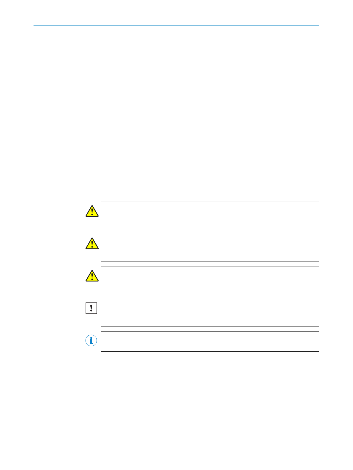
1.3 Symbols and document conventions
The following symbols and conventions are used in this document:
ABOUT THIS DOCUMENT 1
Safety notes and other notes
DANGER
ates a situation presenting imminent danger, which will lead to death or serious
Indic
injuries if not prevented.
WARNING
Indic
ates a situation presenting possible danger, which may lead to death or serious
injuries if not prevented.
CAUTION
Indic
ates a situation presenting possible danger, which may lead to moderate or minor
injuries if not prevented.
NOTICE
ates a situation presenting possible danger, which may lead to property damage if
Indic
not prevented.
NOTE
ates useful tips and recommendations.
Indic
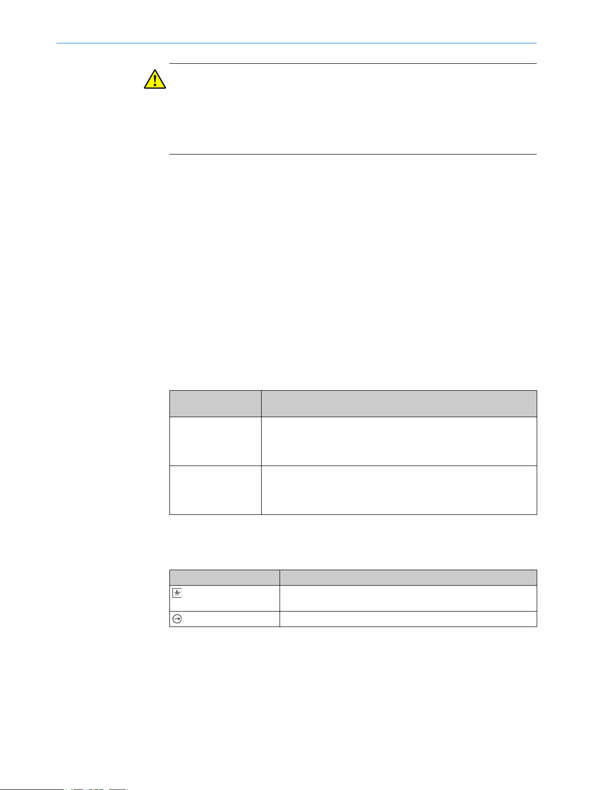
Instructions to action
T
he arrow denotes instructions to action.
b
1. The sequence of instructions for action is numbered.
2. Follow the order in which the numbered instructions are given.
✓
The check mark denotes the result of an instruction.
LED symbols
These symbols indicate the status of an LED:
The LED is off.
o
The LED is flashing.
Ö
8020558//2017-02-14 | SICK O PE R AT I NG IN S TR U CT I ON S | i200 Lock
Subject to change without notice
5
Page 6

BOUT THIS DOCUMENT
1 A
The LED is illuminated continuously.
O
Terminology
angerous state
D
A dangerous state is a status of the machine or facility, where people may be injured.
Protective devices prevent this risk if the machine is operated within its intended use.
The figures in this document always show the dangerous state of the machine as move‐
ment of a machine part. In practice, there are different dangerous states, such as:
Machine movements
•
Electrical parts
•
Visible and invisible beam
•
A combination of multiple hazards
•
6
O PE R AT I NG IN S TR U CT I ON S | i200 Lock 8020558//2017-02-14 | SICK
Subject to change without notice
Page 7

2 Safety information
2.1 General safety notes
The safety locking device must be configured and operated correctly by qualified safety
sonnel according to the machine requirements.
per
2.2 Intended use
When used in conjunction with a movable physical guard and the machine controller,
t
he safety locking device prevents the protective device from being opened while a dan‐
gerous machine function is being executed.
The safety locking device may only be used on the machine on which it was configured,
mounted, installed, and commissioned by qualified safety personnel in accordance with
these operating instructions.
Incorrect use, improper modification of or tampering with the safety locking device will
invalidate any warranty from SICK AG; in addition, any responsibility and liability of SICK
AG for damage and secondary damage caused by this is excluded.
NOTE
The safety locking device is also suitable for process protection.
SAFETY INFORMATION 2
2.3 Requirements for the qualification of personnel
The safety locking device must be configured, installed, connected, commissioned, and
viced only by qualified safety personnel.
ser
Project planning
For project planning, a person is considered competent when he/she has expertise and
experience in the selection and use of protective devices on machines and is familiar
with the relevant technical rules and national work safety regulations.
Mechanical mounting, electrical installation, and commissioning
For the task, a person is considered qualified when he/she has the expertise and expe‐
rience in the relevant field and is sufficiently familiar with the application of the protec‐
tive device on the machine to be able to assess whether it is in an operationally safe
state.
Operation and maintenance
For operation and maintenance, a person is considered competent when he/she has
the expertise and experience in the relevant field and is sufficiently familiar with the
application of the protective device on the machine and has been instructed by the
machine operator in its operation.
8020558//2017-02-14 | SICK O PE R AT I NG IN S TR U CT I ON S | i200 Lock
Subject to change without notice
7
Page 8

3 P
RODUCT DESCRIPTION
3 Product description
3.1 Setup and function
The safety locking device is an interlocking device consisting of a mechanically-actu‐
ted position switch and a coded actuator. The actuator has a lower coding level. The
a
position switch contains a rotating switching cylinder which the actuator grips during
closing. The switching cylinder is locked or unlocked electromagnetically (variantdependent).
When inserting and removing the actuator, switching contacts for door monitoring are
opened and closed. When locking and unlocking the locking device, switching contacts
for locking device monitoring are opened and closed.
If the locking device is locked, the actuator cannot be removed from the actuating head.
The locking device can only be locked when the protective device is closed.
3.2 Product characteristics
3.2.1 Product variants
The safety locking device is delivered in different variants. You will find an overview of
im
portant distinguishing features of the variants in the following.
Locking principle: operating or standby current
•
Type of contacts for locking device monitoring
•
Complete overview of all variants: see "Ordering information", page 22
Standby current locking principle
i200-M
ocking locking device: close protective device, no voltage on the magnet
L
•
Unlocking locking device: apply voltage to magnet
•
If voltage is interrupted at the magnet, the locking device remains locked and the pro‐
tective device cannot be opened immediately.
WARNING
T
he locking device also locks when voltage is not present.
People could get trapped.
If people are in the hazardous area, do not close the protective device even volt‐
b
age is not present.
Operating current locking principle
i200-E
ocking locking device: apply voltage to magnet
L
•
Unlocking locking device: disconnect voltage from magnet
•
If voltage is disconnected at the magnet, the locking device is unlocked and the protec‐
tive device can be opened immediately.
8
O PE R AT I NG IN S TR U CT I ON S | i200 Lock 8020558//2017-02-14 | SICK
Subject to change without notice
Page 9
DANGER
azard due to lack of effectiveness of the protective device
H
In the event of a voltage drop, the safety locking device unlocks regardless of whether
the dangerous state of the machine has ended.
Assess the risk of accident. Use for protecting people requires correct project plan‐
b
ning.
3.2.2 Locking device monitoring
All variants feature at least 1 positive opening normally closed contact for locking
vice monitoring. The output state changes when locking or unlocking the locking
de
device.
Variants with 2 positive opening normally closed contacts for locking device monitoring
are recommended to protect people.
3.2.3 Door monitoring
All versions feature 3 contacts for door monitoring. 2 contacts are positive opening nor‐
mall
y closed contacts. 1 contact is a normally open contact. The output state changes
when opening or closing the protective device.
PRODUCT DESCRIPTION 3
3.2.4 Status indicators
The safety locking device outputs the status of the locking device using the light emit‐
t
ing diode.
Table 1: Status LEDs
Light emitting diode
tus
sta
O
o
3.3 Symbols on the product
Table 2: Symbols on the product
Symbol Meaning
Meaning
Voltage is present on the magnet for the locking device.
With standby current locking principle: locking device unlocked.
With operating current locking principle: locking device locked with
inserted actuator.
No voltage is present on the magnet for the locking device.
ith standby current locking principle: locking device locked with
W
inserted actuator.
With operating current locking principle: locking device unlocked.
Positive opening normally closed contact for locking device moni‐
t
oring
Positive opening normally closed contact for door monitoring
3.4 Manual unlocking
In some situations, it necessary to unlock the locking device manually (e.g. is faults are
esent). After unlocking, a function test must be performed.
pr
Mechanical unlocking mechanism
With the mechanical unlocking mechanism, the safety locking device can be unlocked
regardless of the status.
8020558//2017-02-14 | SICK O PE R AT I NG IN S TR U CT I ON S | i200 Lock
Subject to change without notice
9
Page 10

3 PRODUCT DESCRIPTION
When actuating the mechanical unlocking mechanism, the contacts for locking device
monit
Actuating the mechanical unlocking mechanism
b
b
b
b
b
Figure 1: Mechanical unlocking mechanism
oring open. A stop command must be generated.
Ensure tensile stress is not applied on the actuator.
Loosen safety screw with the screwdriver.
Insert insulated screwdriver with maximum diameter of 2.5 mm into the opening
and activate the mechanical unlocking mechanism.
Open protective device with mechanical unlocking mechanism activated.
Reinsert safety screw.
10
O PE R AT I NG IN S TR U CT I ON S | i200 Lock 8020558//2017-02-14 | SICK
Subject to change without notice
Page 11

4 Project planning
4.1 Manufacturer of the machine
DANGER
F
ailure to comply with manufacturer’s obligations
Hazard due to lack of effectiveness of the protective device
Carry out a risk assessment before using the safety locking device.
b
Do not tamper with or modify the components of the safety locking device.
b
Make sure that the safety locking device is only repaired by the manufacturer or by
b
someone authorized by the manufacturer. Improper repair can lead to a loss of the
protective function.
Make sure that switch-on commands which bring about a dangerous state of the
b
machine are not enabled until the protective device is closed and the lock is acti‐
vated.
Make sure that the lock is not deactivated until the dangerous state of the
b
machine has stopped.
Make sure that closing a protective device and activating the lock does not cause
b
a dangerous machine function to start by itself. This must be controlled by a sepa‐
rate start command.
The safety locking device must not be bypassed (contacts jumpered), turned away,
b
removed, or rendered ineffective in any other way. Take measures to reduce
bypassing options as necessary.
PROJECT PLANNING 4
If several devices are switched in succession and the simplified process according to
O 13849 is used to determine the performance level (PL), the PL may be reduced.
IS
A logical series connection of safe contacts may be possible up to PL d under certain
circumstances. For more detailed information, see ISO TR 24119.
The safety locking device is designed so that internal errors according to ISO 13849-2,
Table A4, can be ruled out.
Observe EN ISO 14119 for using interlocking devices associated with physical guards.
4.1.1 Application of the safety locking device to protect people
At least one safe contact must be used for locking device monitoring (contact assign‐
ment see
table 3).
4.1.2 Application of the safety locking device for process protection
At least one safe contact must be used for door monitoring.
Contacts for locking device monitoring can also be used (pin assignment see
table 3).
8020558//2017-02-14 | SICK O PE R AT I NG IN S TR U CT I ON S | i200 Lock
Subject to change without notice
11
Page 12

4 PROJECT PLANNING
4.2 Operator of the machine
DANGER
ailure to observe operator obligations
F
Hazard due to lack of effectiveness of the protective device
Changes to the machine and changes to the mechanical mounting of the safety
b
locking device necessitate a new risk assessment. The results of this risk assess‐
ment may require the operator of the machine to meet a manufacturer’s obliga‐
tions.
Apart from the procedures described in this document, the components of the
b
safety locking device must not be opened or modified.
Do not carry out any repair work on components. Improper repair of the safety
b
locking device can lead to a loss of the protective function.
Make sure that replacement actuators are not used for bypassing. Restrict access
b
to actuators.
4.3 Design
DANGER
ypassing the protective device
B
Hazard due to lack of effectiveness of the protective device
Eliminate any temptation to tamper with the safety locking device by implementing
b
measures such as the following:
Attach safety switches with a cover or with shielding, or ensure they are out of
°
reach.
Cover the safety switch and the actuator with additional equipment or protect
°
them against access. Cover the sensor and the actuator with additional
equipment or protect them against access.
4.3.1 Selection of the actuator
NOTICE
Se
lecting unsuitable actuators or improper mounting can damage the device.
Select the right actuator (see table 7).
b
Pay attention to the door radius and mounting options.
b
4.4 Integrating into the electrical control
Switch-on commands which bring about a dangerous state of the machine must not be
enabled unt
be deactivated until the dangerous state has ended. Depending on the safety concept,
the signal is analyzed by, e.g., safety relays or a safety controller.
il the protective device is closed and the lock is activated. The lock must not
4.5 Testing plan
12
The safety locking device must be tested by appropriately qualified safety personnel
when commis
The regular thorough checks serve to investigate the effectiveness of the safety locking
device and discover defects because of modifications or external influences (such as
damage or tampering).
O PE R AT I NG IN S TR U CT I ON S | i200 Lock 8020558//2017-02-14 | SICK
sioning, after modifications, and at regular intervals.
Subject to change without notice
Page 13

PROJECT PLANNING 4
The manufacturer and user must define the type and frequency of the thorough checks
on t
he machine on the basis of the application conditions and the risk assessment.
Determination of the thorough checks must be documented in a traceable manner.
8020558//2017-02-14 | SICK O PE R AT I NG IN S TR U CT I ON S | i200 Lock
Subject to change without notice
13
Page 14

5 MOUN
TING
5 Mounting
5.1 Safety
DANGER
H
azard due to unexpected starting of the machine
Death or severe injury
Make sure that the dangerous state of the machine is and remains switched off.
b
DANGER
B
ypassing the protective device
Hazard due to lack of effectiveness of the protective device
Eliminate any temptation to tamper with the safety locking device by taking at least
b
one of the following measures:
Attach safety switches with a cover or with shielding, or ensure they are out of
°
reach.
If possible, use permanent mounting methods for actuators (e.g., welding,
°
glue, disposable screws, or rivets).
NOTICE
If incorrectly installed or the ambient conditions are not suitable, the safety locking
device can get damaged.
Arrange the safety switch and actuator so that damage due to unintentional out‐
b
side influences is prevented.
Do not use safety switch and actuator.
b
The set-up and mounting of the safety switch and actuator must be stable enough
b
to maintain proper operation.
Use only reliable mounting elements that can only be removed with tools.
b
If an opening is created in the physical guard due to alignment errors, it must not
b
impair the protective function.
5.2 Converting the actuating head
1. Insert the actuator into the actuating head.
Loosen screws on the cover and lift the cover.
2.
3. Remove plastic dowel pins and loosen actuating head.
4. Turn the actuating head in the desired direction.
5. Depending on the locking forces, fasten the actuating head with plastic dowel pins
or metal bolts.
6. Rotate metal insert by 180° by loosening the 2 fixing screws.
7. Seal unused actuation slots with the supplied slot covers.
14
O PE R AT I NG IN S TR U CT I ON S | i200 Lock 8020558//2017-02-14 | SICK
Subject to change without notice
Page 15

180°
180°
5.3 Mounting
MOUNTING 5
1. Insert the actuator into the actuating head.
Connect the safety switch to the fixed part of the protective device with positive
2.
locking with 2 M5 screws. Tightening torque: 1.4 Nm.
3. In addition, insert 2 M5 coiled spring pins to fasten the safety switch.
4. Connect the actuator permanently to the moving part of the protective device so it
cannot be disengaged.
5. Fit an additional stop for the moving part of the protective device.
5.4 Protection from environmental influences
The prerequisite for a proper and permanent safety function is protection of the actuat‐
in
g head from foreign bodies such as chips, sand, beams of light, etc.
When doing painting work, cover the actuation slot, the actuator and the type label.
8020558//2017-02-14 | SICK O PE R AT I NG IN S TR U CT I ON S | i200 Lock
Subject to change without notice
15
Page 16

34
2
2
12
33
21
11
54
42
53
41
34
2
2
12
33
21
11
54
42
53
41
34
2
2
12
33
21
11
54
42
53
41
34
2
2
12
33
21
52
42
51
41
11
34
22
12
33
21
52
42
51
41
11
34
2
2
12
33
21
52
42
51
41
11
6 ELE
CTRICAL INSTALLATION
6 Electrical installation
6.1 Safety
DANGER
H
azard due to electrical voltage
Death or severe injury
Make sure that the machine and the connecting cables of the safety locking
b
device are and remain disconnected from the power supply during the electrical
installation.
DANGER
Incor
rect safety locking device connection
Loss of safety function
With insulation material or connection slots, pay attention to the temperature
b
resistance and mechanical load capability.
If different voltages are used between the contact pairs and the magnet coil (e.g.
b
230 V and 24 V), when wiring in the terminal compartment, make sure safe sepa‐
ration is always present.
For safety functions, use only safe contacts for locking device monitoring and door
b
monitoring.
6.2 Pin assignment
Table 3: Switching elements and switching functions
Actuator inserted Actuator removed
Locked Unlocked
i200-*02332
i200-M0413
2)
All variants E1: +24 V DC magnet coil voltage supply (locking device)
E2: +0 V DC magnet coil voltage supply (locking device)
1)
The bridge between contacts 12 and 41 must be removed to in order to enable locking device and door
monit
2)
oring.
The bridges between contacts 12 and 41 and 22 and 51 must be removed to in order to enable locking
device and door monitoring.
6.3 System connection (cable entry)
1. Open desired insertion opening with a suitable tool.
Mount the cable gland with corresponding enclosure rating.
2.
3. Connect contacts (contact assignment see table 3).
Connect all live contacts to one side of the contact block.
°
Operate all contact pairs and the magnet coil in the same voltage range.
°
Protect the magnet coil separately.
°
Tighten terminals to 1.0 Nm.
°
16
O PE R AT I NG IN S TR U CT I ON S | i200 Lock 8020558//2017-02-14 | SICK
Subject to change without notice
Page 17

ELECTRICAL INSTALLATION 6
4. Pay attention to tightness of the cable entries.
5.
Close switch cover and fasten it (tightening torque 1.2 Nm).
8020558//2017-02-14 | SICK O PE R AT I NG IN S TR U CT I ON S | i200 Lock
Subject to change without notice
17
Page 18

7 C
OMMISSIONING
7 Commissioning
7.1 Testing
DANGER
H
azard due to unexpected starting of the machine
Death or severe injury
Before carrying out the functional test, make sure that there are no people in the
b
hazardous area.
Check that the device is functioning properly after installation and after every fault. To
his, proceed as follows:
do t
Mechanical functional test
Open the protective device and close it again. The components of the safety lock‐
b
ing device must not collide with other parts. When the protective device is closed,
the actuator must be in a position which enables the lock to be actuated.
Electrical functional test
1. Switch on the supply voltage.
2. Close all protective devices and activate the locks. The machine must not start up
on its own.
3. Check the lock. It must not be possible to open the protective device.
4. Start the machine function.
5. Make sure that the lock cannot be deactivated as long as the dangerous machine
function is active.
6. Stop the machine function and deactivate the lock.
7. Check whether the protective device is kept locked until there is no more risk of
injury (e.g., due to run-on movements).
8. Check the restart interlock. The machine function must not start while the lock is
deactivated.
9. Repeat steps 3 to 8 individually for each protective device.
NOTE
In t
he case of the “power to lock” version, an active locking command can be simulated
by applying a 24 V DC voltage at the “lock input” contact.
7.2 Recurring technical checks
DANGER
Insuf
ficient checks or incorrect repair
Hazard due to lack of effectiveness of the protective device
In the event of wear or damage, replace the entire safety locking device with
b
actuator. Never replace individual parts or assemblies.
Check the safety locking device following the inspection intervals specified in the
b
national rules and regulations.
The following checks must be done to ensure permanent and proper function:
oper switching function
Pr
•
Safe mounting for all components
•
No damage, contamination, deposits or wear
•
Tightness of cable entries
•
18
O PE R AT I NG IN S TR U CT I ON S | i200 Lock 8020558//2017-02-14 | SICK
Subject to change without notice
Page 19

o loose cable connections or plug connectors
N
•
No manipulation by employees
•
COMMISSIONING 7
8020558//2017-02-14 | SICK O PE R AT I NG IN S TR U CT I ON S | i200 Lock
Subject to change without notice
19
Page 20

8 TECHNICAL DATA
8 Technical data
8.1 Technical data
Table 4: Features
Features
Housing material Fiberglass-reinforced polyester
Enclosure rating (IEC 60529) IP 65
Mechanical service life 1 × 10
B
(EN IS
10d
Type Type 2 (EN ISO 14119)
Coding level of the actuator Low coding level (EN ISO 14119)
Ambient operating temperature –20 °C … +60 °C
Connection type 3 × M20
Max. actuation speed 9.6 m × min
Max. actuation frequency 3,600 × h
Pollution degree
xternal, according to EN 60947)
(e
Max. force against which unlocking is possible 50 N
Max. retaining force, unlocked 30 N
Locking force F
Mounting with plastic locating pins
Mount
Locking force FZh ac
(FZh = F
Mounting with plastic locating pins
Mount
Minimum door radii see table 7
Variant with cable entry
6
O 13849) 2 × 10⁶ Switching operation with small load
–1
–1
3 × (industry)
x
ma
1,950 N
ing with metal bolts
2,600 N
cording to (EN ISO 14119)
/1.3)
max
1,500 N
ing with metal bolts
2,000 N
20
Table 5: Electrical data
Electrical data
Thermal current l
t
h
10 A
Switching principle Slow action switching element
Wire cross-section, (rigid/flexible) 0.34 mm2 ... 1.5 mm
Rated insulation voltage U
i
Rated impulse withstand voltage U
p
im
250 V
2.5 kV
2
Utilization category (IEC 60947-5-1) AC-15: 230 V, 3 A; DC-13: 24 V, 3 A
Min. switching voltage
1)
5 V
Min. switching current at 24 V DC 5 mA
Short-circuit protection (control fuse) (IEC
6 A gG
60269)
Solenoid supply voltage (+10% … –15%) AC/DC 24 V
Max. solenoid power 7 W
ED switch-on time 100%
1)
At 10 mA.
O PE R AT I NG IN S TR U CT I ON S | i200 Lock 8020558//2017-02-14 | SICK
Subject to change without notice
Page 21

8.2 Dimensional drawings
126
105
9
14
2121
43
6,5 5
67,5
60,5
52,5
31,5
4
33
14
27
37
93
80
19 21 21
5
5,5
20,5
25,5
M5
52
40
31
18
20
8
6,8
4 x 5,5
2 x M3
51
19
13
52
40
18
36
4
14, 5
3,5
M5
i200 Lock
TECHNICAL DATA 8
Actuator
8020558//2017-02-14 | SICK O PE R AT I NG IN S TR U CT I ON S | i200 Lock
Subject to change without notice
Figure 2: iE200-F1
Figure 3: iE200-S1
21
Page 22

9 ORDERING INFORMATION
9 Ordering information
9.1 Ordering information
Table 6: Ordering information, i200 Lock
Locking principle Locking device monitoring Type code Part number
Positive opening
mally closed
nor
contact
Standby current 1 1 i200-M0323 Lock 6025113
Standby current 2 0 i200-M0413 Lock 6025115
Operating current 1 1 i200-E0323 Lock 6026140
Normally open
22
O PE R AT I NG IN S TR U CT I ON S | i200 Lock 8020558//2017-02-14 | SICK
Subject to change without notice
Page 23

ACCESSORIES 10
10 Accessories
10.1 Actuator
Table 7: Actuator
Design Actuation option Door radius Type code Part number
Straight Rigid ≥ 160 mm iE200-S1 5308758
Radial Fully flexible ≥ 80 mm iE200-F1 5308759
Bolt actuator, straight Rigid ≥ 160 mm iE200-B1 5308760
10.2 Additional accessories
Table 8: Additional accessories
Designation Type code Part number
Cable gland M20 screw connection 5309164
8020558//2017-02-14 | SICK O PE R AT I NG IN S TR U CT I ON S | i200 Lock
Subject to change without notice
23
Page 24

11 ANNE
X
11 Annex
11.1 Compliance with EU directives
EU declaration of conformity (excerpt)
he undersigned, representing the following manufacturer herewith declares that the
T
product is in conformity with the provisions of the following EU directive(s) (including all
applicable amendments), and that the respective standards and/or technical specifica‐
tions are taken as the basis.
Complete EU declaration of conformity for download
You can call up the EU declaration of conformity and the current operating instructions
for the protective device by entering the part number in the search field at
www.sick.com (part number: see the type label entry in the “Ident. no.” field).
24
O PE R AT I NG IN S TR U CT I ON S | i200 Lock 8020558//2017-02-14 | SICK
Subject to change without notice
Page 25

ANNEX 11
8020558//2017-02-14 | SICK O PE R AT I NG IN S TR U CT I ON S | i200 Lock
Subject to change without notice
25
Page 26

11 ANNEX
26
O PE R AT I NG IN S TR U CT I ON S | i200 Lock 8020558//2017-02-14 | SICK
Subject to change without notice
Page 27

ANNEX 11
8020558//2017-02-14 | SICK O PE R AT I NG IN S TR U CT I ON S | i200 Lock
Subject to change without notice
27
Page 28

Australia
Phone +61 3 9457 0600
1800 334 802 – tollfree
E-Mail sales@sick.com.au
Austria
Phone +43 22 36 62 28 8-0
E-Mail office@sick.at
Belgium/Luxembourg
Phone +32 2 466 55 66
E-Mail info@sick.be
Brazil
Phone +55 11 3215-4900
E-Mail marketing@sick.com.br
Canada
Phone +1 905 771 14 44
E-Mail information@sick.com
Czech Republic
Phone +420 2 57 91 18 50
E-Mail sick@sick.cz
Chile
Phone +56 2 2274 7430
E-Mail info@schadler.com
China
Phone +86 20 2882 3600
E-Mail info.china@sick.net.cn
Denmark
Phone +45 45 82 64 00
E-Mail sick@sick.dk
Finland
Phone +358-9-2515 800
E-Mail sick@sick.fi
France
Phone +33 1 64 62 35 00
E-Mail info@sick.fr
Germany
Phone +49 211 5301-301
E-Mail info@sick.de
Hong Kong
Phone +852 2153 6300
E-Mail ghk@sick.com.hk
Hungary
Phone +36 1 371 2680
E-Mail office@sick.hu
India
Phone +91 22 4033 8333
E-Mail info@sick-india.com
Israel
Phone +972 4 6881000
E-Mail info@sick-sensors.com
Italy
Phone +39 02 274341
E-Mail info@sick.it
Japan
Phone +81 3 5309 2112
E-Mail support@sick.jp
Malaysia
Phone +6 03 8080 7425
E-Mail enquiry.my@sick.com
Mexico
Phone +52 472 748 9451
E-Mail mario.garcia@sick.com
Netherlands
Phone +31 30 2044 000
E-Mail info@sick.nl
New Zealand
Phone +64 9 415 0459
0800 222 278 – tollfree
E-Mail sales@sick.co.nz
Norway
Phone +47 67 81 50 00
E-Mail sick@sick.no
Poland
Phone +48 22 539 41 00
E-Mail info@sick.pl
Romania
Phone +40 356 171 120
E-Mail office@sick.ro
Russia
Phone +7 495 775 05 30
E-Mail info@sick.ru
Singapore
Phone +65 6744 3732
E-Mail sales.gsg@sick.com
Slovakia
Phone +421 482 901201
E-Mail mail@sick-sk.sk
Slovenia
Phone +386 591 788 49
E-Mail office@sick.si
South Africa
Phone +27 11 472 3733
E-Mail info@sickautomation.co.za
South Korea
Phone +82 2 786 6321
E-Mail info@sickkorea.net
Spain
Phone +34 93 480 31 00
E-Mail info@sick.es
Sweden
Phone +46 10 110 10 00
E-Mail info@sick.se
Switzerland
Phone +41 41 619 29 39
E-Mail contact@sick.ch
Taiwan
Phone +886 2 2375-6288
E-Mail sales@sick.com.tw
Thailand
Phone +66 2645 0009
E-Mail Ronnie.Lim@sick.com
Turkey
Phone +90 216 528 50 00
E-Mail info@sick.com.tr
United Arab Emirates
Phone +971 4 88 65 878
E-Mail info@sick.ae
United Kingdom
Phone +44 1727 831121
E-Mail info@sick.co.uk
USA
Phone +1 800 325 7425
E-Mail info@sick.com
Vietnam
Phone +84 945452999
E-Mail Ngo.Duy.Linh@sick.com
Further locations at www.sick.com
8020558//2017-02-14/en
SICK AG | Waldkirch | Germany | www.sick.com
 Loading...