

Page 1
Title Page
SUPPLEMENTARY OPERATING INSTRUCTIONS
GMS815P-PS-2G / GMS815P-PS-3G
Enclosures for GMS800 Series
Description
Installation
Technical data
GMS815P-PS-2G
Page 2
Document Information
Described Product
Product name: GMS815P-PS-2G/-3G (product variants with
pressurized enclosure system)
Basic device: GMS800 Series gas analyzers
Document ID
Title: Supplementary Operating Instructions
GMS815P-PS-2G/-3G
Part No.: 8016234
Version: 2.0
Release: 2013-02
Manufacturer
SICK AG
Erwin-Sick-Str. 1 · 79183 Waldkirch · Germany
Phone: +49 7641 469-0
Fax: +49 7641 469-1149
E-Mail: info.pa@sick.de
Place of manufacture
SICK AG
Poppenbütteler Bogen 9 b · 22399 Hamburg · Germany
Trademarks
Swagelok is a trademark of the Swagelok Company.
Other product names used in this document may also be trademarks and are only used for identification purposes.
Original documents
The English edition 8016234 of this document is an original
document of SICK AG.
SICK AG assumes no liability for the correctness of an unauthorized translation.
Please contact SICK AG or your local representative in case of
doubt.
Legal information
Subject to change without notice
Warning Symbols
Hazard (general)
Hazard in potentially explosive atmospheres
Hazard by explosive substances/mixtures
Hazard by toxic substances
Warning Levels / Signal Words
WARNING
Risk or hazardous situation which could result in severe personal
injury or death.
CAUTION
Hazard or unsafe practice which could result in personal injury or
property damage.
NOTICE
Hazard which could result in property damage.
Information Symbols
Information on product characteristics with regard to
protection against explosions
© SICK AG. All rights reserved.
Glossary
AC Alternating Current
IP XY International Protection (also: Ingress Protection);
degree of protection of a device according to IEC/
DIN EN 60529. The digit X designates protection
against contact and impurities, Y protection against
moisture.
Important technical information for this product
Important information on electric or electronic functions
Supplementary information
Link to information at another place
2 GMS815P-PS-2G/-3G · Supplementary Operating Instructions · 8016234 V2.0 · © SICK AG
Page 3

Contents
Contents
1Important Information . . . . . . . . . . . . . . . . . . . . . . . . . . . . . . . . . . . . . . . . . . . . . . . 5
1.1 Main hazards . . . . . . . . . . . . . . . . . . . . . . . . . . . . . . . . . . . . . . . . . . . . . . . . . . . . . . . . . . . . . . . . 6
1.2 Main operating information. . . . . . . . . . . . . . . . . . . . . . . . . . . . . . . . . . . . . . . . . . . . . . . . . . . . 6
1.3 Safety during installation and repairs. . . . . . . . . . . . . . . . . . . . . . . . . . . . . . . . . . . . . . . . . . . 7
1.4 Additional documentation/information . . . . . . . . . . . . . . . . . . . . . . . . . . . . . . . . . . . . . . . . . 7
1.5 Application limitations . . . . . . . . . . . . . . . . . . . . . . . . . . . . . . . . . . . . . . . . . . . . . . . . . . . . . . . . 8
1.5.1 Approval conditions for the Enclosure GMS815P-PS-2G. . . . . . . . . . . . . . . . . . . . . . . . 8
1.5.2 Approval conditions for the Enclosure GMS815P-PS-3G. . . . . . . . . . . . . . . . . . . . . . . . 8
2 Product Description . . . . . . . . . . . . . . . . . . . . . . . . . . . . . . . . . . . . . . . . . . . . . . . . . . . 9
2.1 Product identification . . . . . . . . . . . . . . . . . . . . . . . . . . . . . . . . . . . . . . . . . . . . . . . . . . . . . . . . 10
2.2 Product characteristics. . . . . . . . . . . . . . . . . . . . . . . . . . . . . . . . . . . . . . . . . . . . . . . . . . . . . . . 11
2.2.1 Common characteristics . . . . . . . . . . . . . . . . . . . . . . . . . . . . . . . . . . . . . . . . . . . . . . . . . . . 11
2.2.2 Differing features . . . . . . . . . . . . . . . . . . . . . . . . . . . . . . . . . . . . . . . . . . . . . . . . . . . . . . . . . 12
2.2.3 Options . . . . . . . . . . . . . . . . . . . . . . . . . . . . . . . . . . . . . . . . . . . . . . . . . . . . . . . . . . . . . . . . . .12
2.3 Function of the pressurized enclosure system . . . . . . . . . . . . . . . . . . . . . . . . . . . . . . . . . .12
3 Installation . . . . . . . . . . . . . . . . . . . . . . . . . . . . . . . . . . . . . . . . . . . . . . . . . . . . . . . . . . . . . 13
3.1 Safety information. . . . . . . . . . . . . . . . . . . . . . . . . . . . . . . . . . . . . . . . . . . . . . . . . . . . . . . . . . . 14
3.1.1 Safety during transport and assembly . . . . . . . . . . . . . . . . . . . . . . . . . . . . . . . . . . . . .14
3.1.2 Protection against dangerous sample gases . . . . . . . . . . . . . . . . . . . . . . . . . . . . . . . . . 14
3.2 Assembly . . . . . . . . . . . . . . . . . . . . . . . . . . . . . . . . . . . . . . . . . . . . . . . . . . . . . . . . . . . . . . . . . . .15
3.2.1 Ensuring ambient conditions . . . . . . . . . . . . . . . . . . . . . . . . . . . . . . . . . . . . . . . . . . . . . . . 15
3.2.2 Fitting the enclosure . . . . . . . . . . . . . . . . . . . . . . . . . . . . . . . . . . . . . . . . . . . . . . . . . . . . . . 15
3.2.3 Removing transport safety devices. . . . . . . . . . . . . . . . . . . . . . . . . . . . . . . . . . . . . . . . . .15
3.3 Gas connections . . . . . . . . . . . . . . . . . . . . . . . . . . . . . . . . . . . . . . . . . . . . . . . . . . . . . . . . . . . . 16
3.3.1 Feeding protective gas . . . . . . . . . . . . . . . . . . . . . . . . . . . . . . . . . . . . . . . . . . . . . . . . . . . . 16
3.3.2 Discharging protective gas . . . . . . . . . . . . . . . . . . . . . . . . . . . . . . . . . . . . . . . . . . . . . . . . . 16
3.3.3 Feeding sample gas . . . . . . . . . . . . . . . . . . . . . . . . . . . . . . . . . . . . . . . . . . . . . . . . . . . . . . . 17
3.3.4 Feeding purge gas to an Analyzer module (option). . . . . . . . . . . . . . . . . . . . . . . . . . . .17
3.4 Cable installation (general information). . . . . . . . . . . . . . . . . . . . . . . . . . . . . . . . . . . . . . . .18
3.4.1 Using suitable cables . . . . . . . . . . . . . . . . . . . . . . . . . . . . . . . . . . . . . . . . . . . . . . . . . . . . . . 18
3.4.2 Closing off cable inlets correctly . . . . . . . . . . . . . . . . . . . . . . . . . . . . . . . . . . . . . . . . . . .18
3.5 Main electrical connection . . . . . . . . . . . . . . . . . . . . . . . . . . . . . . . . . . . . . . . . . . . . . . . . . . . 19
3.5.1 Preparing mains connection . . . . . . . . . . . . . . . . . . . . . . . . . . . . . . . . . . . . . . . . . . . . . . . 19
3.5.2 Establishing potential equalization (earth) . . . . . . . . . . . . . . . . . . . . . . . . . . . . . . . . . . . 19
3.5.3 Connecting the mains connection . . . . . . . . . . . . . . . . . . . . . . . . . . . . . . . . . . . . . . . . . . 19
3.6 Alarm signal of the pressurized enclosure system . . . . . . . . . . . . . . . . . . . . . . . . . . . . . .20
3.7 Signal connections (I/O) in the interface box . . . . . . . . . . . . . . . . . . . . . . . . . . . . . . . . . . . 20
3.7.1 Function of the interface box . . . . . . . . . . . . . . . . . . . . . . . . . . . . . . . . . . . . . . . . . . . . . . . 20
3.7.2 Connecting signal cables in the interface box . . . . . . . . . . . . . . . . . . . . . . . . . . . . . . . . 20
3.8 Signal connections (I/O) in the gas analyzer enclosure . . . . . . . . . . . . . . . . . . . . . . . . . . 22
3.8.1 Opening the gas analyzer enclosure . . . . . . . . . . . . . . . . . . . . . . . . . . . . . . . . . . . . . . . .22
3.8.2 Installing signal cables on the gas analyzer enclosure . . . . . . . . . . . . . . . . . . . . . . . . 22
3.8.3 Establishing signal connections (I/O) in the gas analyzer enclosure . . . . . . . . . . . . 23
3.8.4 Connecting the interfaces (as required) . . . . . . . . . . . . . . . . . . . . . . . . . . . . . . . . . . . . .23
GMS815P-PS-2G/-3G · Supplementary Operating Instructions · 8016234 V2.0 · © SICK AG 3
Page 4

Contents
3.9 Intrinsically safe signal connections (option) . . . . . . . . . . . . . . . . . . . . . . . . . . . . . . . . . . . 24
3.9.1 Technical layout of the intrinsically safe signal connections . . . . . . . . . . . . . . . . . . . 24
3.9.2 Special technical data for intrinsically safe signal connections . . . . . . . . . . . . . . . . 24
3.9.3 Installation information for intrinsically safe signal connections . . . . . . . . . . . . . . . 25
3.9.4 Electronic alarm settings for intrinsically safe signal connections. . . . . . . . . . . . . . 25
3.10 Sealing the enclosure . . . . . . . . . . . . . . . . . . . . . . . . . . . . . . . . . . . . . . . . . . . . . . . . . . . . . . . 26
4 Start-up/Shutdown . . . . . . . . . . . . . . . . . . . . . . . . . . . . . . . . . . . . . . . . . . . . . . . . . . 27
4.1 Start-up . . . . . . . . . . . . . . . . . . . . . . . . . . . . . . . . . . . . . . . . . . . . . . . . . . . . . . . . . . . . . . . . . . . . 28
4.2 Shutdown . . . . . . . . . . . . . . . . . . . . . . . . . . . . . . . . . . . . . . . . . . . . . . . . . . . . . . . . . . . . . . . . . . 28
5 Maintenance . . . . . . . . . . . . . . . . . . . . . . . . . . . . . . . . . . . . . . . . . . . . . . . . . . . . . . . . . . 29
5.1 Function test of the pressurized enclosure system . . . . . . . . . . . . . . . . . . . . . . . . . . . . . 30
5.2 Leak tightness checks . . . . . . . . . . . . . . . . . . . . . . . . . . . . . . . . . . . . . . . . . . . . . . . . . . . . . . 30
5.2.1 Leak tightness check of the sample gas lines. . . . . . . . . . . . . . . . . . . . . . . . . . . . . . . . 30
5.2.2 Leak tightness check of the purge gas paths . . . . . . . . . . . . . . . . . . . . . . . . . . . . . . . . 30
6Technical Data. . . . . . . . . . . . . . . . . . . . . . . . . . . . . . . . . . . . . . . . . . . . . . . . . . . . . . . . 31
6.1 Dimensions. . . . . . . . . . . . . . . . . . . . . . . . . . . . . . . . . . . . . . . . . . . . . . . . . . . . . . . . . . . . . . . . . 32
6.2 Approvals . . . . . . . . . . . . . . . . . . . . . . . . . . . . . . . . . . . . . . . . . . . . . . . . . . . . . . . . . . . . . . . . . . 33
6.3 Enclosure specifications . . . . . . . . . . . . . . . . . . . . . . . . . . . . . . . . . . . . . . . . . . . . . . . . . . . . . 33
6.4 Ambient conditions . . . . . . . . . . . . . . . . . . . . . . . . . . . . . . . . . . . . . . . . . . . . . . . . . . . . . . . . . 33
6.5 Gas connections . . . . . . . . . . . . . . . . . . . . . . . . . . . . . . . . . . . . . . . . . . . . . . . . . . . . . . . . . . . . 34
6.6 Mains connection . . . . . . . . . . . . . . . . . . . . . . . . . . . . . . . . . . . . . . . . . . . . . . . . . . . . . . . . . . . 34
6.7 Electrical safety . . . . . . . . . . . . . . . . . . . . . . . . . . . . . . . . . . . . . . . . . . . . . . . . . . . . . . . . . . . . . 35
6.8 Pressurized enclosure parameters . . . . . . . . . . . . . . . . . . . . . . . . . . . . . . . . . . . . . . . . . . . . 35
6.8.1 Protective gas . . . . . . . . . . . . . . . . . . . . . . . . . . . . . . . . . . . . . . . . . . . . . . . . . . . . . . . . . . . . 35
6.8.2 Enclosure parameters . . . . . . . . . . . . . . . . . . . . . . . . . . . . . . . . . . . . . . . . . . . . . . . . . . . . 35
6.8.3 Pressurized enclosure system setting for Enclosure GMS815P-PS-2G. . . . . . . . . . 35
6.8.4 Pressurized enclosure system setting for Enclosure GMS815P-PS-3G. . . . . . . . . . 36
4 GMS815P-PS-2G/-3G · Supplementary Operating Instructions · 8016234 V2.0 · © SICK AG
Page 5

Important Information
GMS815P-PS-2G/-3G
1 Important Information
Product description
Main information
Additional information
Subject to change w ithout notice
GMS815P-PS-2G/-3G · Supplementary Operating Instructions · 8016234 V2.0 · © SICK AG 5
Page 6
1.1 Main hazards
Health risks through dangerous sample gases
▸
→ “GMS800 series” Operating Instructions
When shutting down
WARNING: Risk of explosions
▸
Do not open the enclosure when an explosive atmosphere is present.
▸
Wait at least 60 minutes after disconnecting from the mains voltage before
opening the enclosure.
▸
Observe the safety information on the enclosure.
1.2 Main operating information
Before start-up
▸
Make sure the internal mains switch is switched on (→ p. 22, Fig. 4).
▸
Close the enclosure tight.
▸
If the enclosure is deformed or damaged: Do not put the GMS800 into operation and
secure against unauthorized start-up.
Start-up/operation
▸
Carry out start-up and shutdown in accordance with the Operating Instructions delivered with the pressurized enclosure system.
▸
Do not open the enclosure during operation.
▸
Before shutting down: Purge the sample gas path with a dry neutral gas to prevent condensation in the measuring system.
▸
Service information: Always wait at least 30 seconds between single switch-on actions
(cooling time for the switch-on current limiter).
Important Information
In hazardous situations
▸
Switch-off the emergency switch or main switch of the host system.
▸
If liquid has penetrated the enclosure: Shut the GMS800 down immediately and disconnect mains voltage at external source.
● The GMS800 is switched off automatically should the protective gas feed
fail.
● Pressurized enclosure parameters → p. 35, §6.8
Subject to change w ithout notice
6 GMS815P-PS-2G/-3G · Supplementary Operating Instructions · 8016234 V2.0 · © SICK AG
Page 7
Important Information
1.3 Safety during installation and repairs
▸
Only use the Enclosure GMS815P-PS-2G/-3G in potentially explosive atmospheres
when permitted according to the zone, explosion group and temperature class specifications (refer to the type plate → p. 10, §2.1).
▸
Observe and follow the “special requirements” of the approval (→ p. 8, §1.5).
▸
Observe and follow the Operating Instructions delivered with the pressurized enclosure
system as well.
▸
Only allow skilled persons having knowledge of the relevant rules and regulations for
potentially explosive atmospheres to carry out installation, start-up, maintenance and
test – e.g.:
– Range specification
– Ignition protection types
– Installation regulations, e.g. “Regulation concerning electrical equipment in hazard-
ous areas (ElexV)”
▸
Only have the device repaired by the manufacturer or by trained and authorized skilled
persons.
▸
Do not make any unauthorized modifications to the device.
1.4 Additional documentation/information
This document supplements the Operating Instructions “GMS800 Series”. It extends these
Operating Instructions with technical information on the Enclosures GMS815P-PS-2G and
GMS815P-PS-3G.
▸
Observe the Operating Instructions delivered with the “GMS800 Series”.
The “GMS800 Series” Operating Instructions also specify all further documents belonging to the individual device.
NOTICE:
▸
Pay primary attention to any individual information delivered.
Other documents delivered
Operating Instructions for the pressurized
enclosure system
Operating Instructions for the main switch
Operating Instructions for the Zener
barriers
[1] Only for versions with intrinsically safe signal connections (→ p. 24, § 3.9)
Subject to change w ithout notice
[1]
▸
Observe during start-up and shutdown.
▸
Observe when installing the mains connection (→ p. 19, §3.5.3).
▸
Observe when installing intrinsically safe
signal connections.
GMS815P-PS-2G/-3G · Supplementary Operating Instructions · 8016234 V2.0 · © SICK AG 7
Page 8
1.5 Application limitations
1.5.1 Approval conditions for the Enclosure GMS815P-PS-2G
Extract from the approval document:
1. The volume flow of sample gas on the system must be restricted to maximum
100 dm³/h.
2. – Sample gases must not be combustible,
or
– sample gas concentrations must always be maximal 25% of the LEL,
or
– sample gases can be combustible but not explosive; the oxygen part must be
below 2% by volume and less than 80% of the upper explosion limit.
3. Sample gas lines connected must be checked for leak tightness and strength using
1.5 times the maximum allowable pressure.
4. Wait at least 60 minutes after disconnecting from the mains voltage before opening
the enclosure (refer to the warning information).
5. Observe manufacturer's Operating Instructions especially with regard to the resistance of the relevant seal materials and gas lines against the sample gases.
Important Information
1.5.2 Approval conditions for the Enclosure GMS815P-PS-3G
Extract from the approval document:
1. – Sample gases must not be combustible,
or
– sample gas concentrations must always be maximal 25% of the lower explosion
limit (LEL).
2. Sample gas lines connected must be checked for leak tightness and strength using
1.5 times the maximum allowable pressure.
8 GMS815P-PS-2G/-3G · Supplementary Operating Instructions · 8016234 V2.0 · © SICK AG
Subject to change w ithout notice
Page 9

Product Description
GMS815P-PS-2G/-3G
2 Product Description
Product variants
Characteristics
Options
Subject to change w ithout notice
GMS815P-PS-2G/-3G · Supplementary Operating Instructions · 8016234 V2.0 · © SICK AG 9
Page 10
2.1 Product identification
These Supplementary Operating Instructions are only valid for Enclosure
GMS815P-PS-3G and Enclosure GMS815P-PS-2G.
▸
Observe the product identification on the type plate.
Type plate
The type plate is located on the right side of the enclosure. The product name of the enclosure is shown on the type plate.
Information on the type plate → Operating Instructions “GMS800 Series”.
Overview of the enclosures of model GMS815
Product name Main feature
GMS815P Standard version (degree of protection IP 65)
GMS815P-3G Vapor-proof leak tightness, approved for Category “3 G”
GMS815P-PS-3G With pressurized enclosure system, approved for Cate-
GMS815P-PS-2G With pressurized enclosure system, approved for Cate-
Product Description
potentially explosive atmospheres
gory “3 G” potentially explosive atmospheres
gory “2 G” potentially explosive atmospheres
10 GMS815P-PS-2G/-3G · Supplementary Operating Instructions · 8016234 V2.0 · © SICK AG
Subject to change w ithout notice
Page 11
Product Description
1
3
4
6
5
7
8
9
10
11
13
12
2
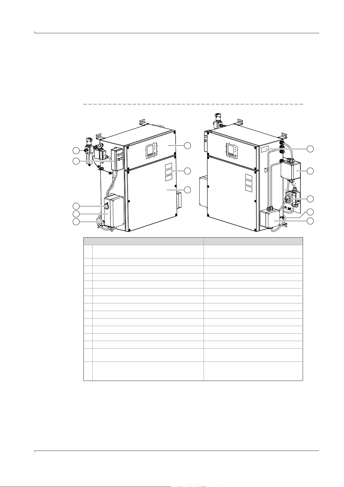
2.2 Product characteristics
2.2.1 Common characteristics
● Designed for wall mounting indoors
● Gas analyzer enclosure with two sections separated gas-tight
● Pressurized enclosure system on the gas analyzer enclosure
Fig. 1 Enclosure GMS815P-PS-2G (similar: GMS815P-PS-3G)
Component Information
1 Gas analyzer enclosure, top section Contains the power supply unit, operating
unit, I/O module
2 Safety information → p. 28, §4.2
3 Gas analyzer enclosure, bottom section Contains the Analyzer module, Gas module
4 Bonding load connection → p. 19, §3.5.2
5 Pressurized enclosure system
6 Protective gas outlet → p. 16, §3.3.2
7 Operating unit of the pressurized enclosure system Only for Enclosure GMS815P-PS-2G
[1]
8 Protective gas inlet → p. 16, §3.3.1
9Type plate → p. 10, §2.1
10 Power relay For mains voltage
11 Main switch → p. 19, §3.5.3
12 Bonding load connection → p. 19, §3.5.2
13 Interface box → p. 20, §3.7.1
– Sample gas connections
[2]
→ Operating Instructions for GMS800 series
gas analyzers
– Option:
[1] → Operating Instructions of the pressurized enclosure system
[2] On the underside of the gas analyzer enclosure (not shown)
Subject to change w ithout notice
[2]
Span gas connection
or connection for second sample gas path
or purge gas connection for an Analyzer module
→ Operating Instructions for GMS800 series
gas analyzers or Supplementary Operating
Instructions of the Analyzer module
GMS815P-PS-2G/-3G · Supplementary Operating Instructions · 8016234 V2.0 · © SICK AG 11
Page 12
2.2.2 Differing features
● Usable in potentially explosive atmospheres in the particular zone, explosion group and
temperature class specified on the type plate (→ p. 10, §2.1).
● Limitations on product variants to be maintained vary when measuring combustible
gases (→ p. 8, §1.5).
● The interface box (→ p. 11, Fig. 1) is always fitted on the Enclosure GMS815P-PS-2G and
is an option for the Enclosure GMS815P-PS-3G.
▸
If the Enclosure GMS815P-PS-3G does not have an interface box fitted:
Maintain the requirements in accordance with EN 60079-2 “Explosive
atmospheres – Part 2: Equipment protection by pressurized enclosure “p””
/Section 7.
● Function of the interface box → p. 20, §3.7.1
● It may be necessary to use the interface box due to the planned operating
conditions.
2.2.3 Options
● Intrinsically safe signal connections
● Interface box (only for GMS815P-PS-3G)
● Version for temperature class “T6” (in preparation)
Product Description
2.3 Function of the pressurized enclosure system
Purpose
The pressurized enclosure prevents an explosive atmosphere being created inside the
enclosure. To this purpose, the gas analyzer enclosure is filled with a protective gas. Apart
from that, it also ensures the gas pressure inside the gas analyzer enclosure is higher than
the ambient air pressure.
Safety functions
● The enclosure is pre-purged automatically before start-up. The mains supply for the gas
analyzer is first switched on afterwards.
● The mains supply of the gas analyzer is switched off automatically should the pressurized enclosure not be in the correct operating state (malfunction).
Functionality during operation
The pressurized enclosure system functions in “leakage compensation” operating mode: A
certain protective gas pressure is created in the gas analyzer enclosure after pre-purging
has completed. If the protective gas pressure drops below the minimum pressure set, protective gas feed is activated until the rated pressure is reached again.
On the Enclosure GMS815P-PS-2G, a certain amount of protective gas leaks out of the gas
analyzer enclosure through the protective gas outlet. This means the protective gas feed is
activated often to restore the pressure. This creates a more or less permanent protective
gas flow with the required flowrate.
12 GMS815P-PS-2G/-3G · Supplementary Operating Instructions · 8016234 V2.0 · © SICK AG
Subject to change w ithout notice
Page 13

Installation
GMS815P-PS-2G/-3G
3 Installation
Cable installation
Assembly
Connections
▸
Let skilled persons with the necessary technical knowledge carry out the
installation (refer also to → p. 7, § 1.3).
▸
Observe and maintain the regulations and specifications of the associated
approval.
Subject to change w ithout notice
GMS815P-PS-2G/-3G · Supplementary Operating Instructions · 8016234 V2.0 · © SICK AG 13
Page 14

3.1 Safety information
3.1.1 Safety during transport and assembly
CAUTION: Risk of injuries
The weight of the enclosure can cause injuries when the device is not lifted in
an ergonomical way.
During transport and assembly:
▸
Consider the weight of the enclosure before lifting (→ p. 33, §6.3).
▸
Call in further personnel as assistants as required.
CAUTION: Risk of injuries
There is a risk of injuries should the enclosure drop down due to the weight of
the device and through hard, protruding enclosure parts.
During transport and assembly:
▸
Wear safety shoes. Use non-slip gloves.
▸
Handle the device carefully and safely. Secure during transport. Avoid falls
and collisions.
▸
Call in further personnel as assistants as required.
NOTICE: Risk of damage
▸
Do not use gas connections and cable inlets as lifting points.
Installation
NOTICE: Risk through transport safety devices
▸
Remove transport safety devices before start-up (→ p. 15, §3.2.3).
Otherwise electronic components can overheat during operation.
3.1.2 Protection against dangerous sample gases
If the sample gas can be dangerous to health, combustible and/or corrosive:
▸
Make sure no dangerous situations can arise should a gas leak occur.
▸
Check
– whether a gas detector must be installed at the installation location
– whether the enclosure must be purged continuously with a neutral gas during oper-
ation (with monitoring the discharged purge gas as required).
Install appropriate additional devices as necessary.
▸
Check gas paths regularly for leak tightness.
14 GMS815P-PS-2G/-3G · Supplementary Operating Instructions · 8016234 V2.0 · © SICK AG
Subject to change w ithout notice
Page 15

Installation
3.2 Assembly
3.2.1 Ensuring ambient conditions
Quiet running
▸
Protect the device against heavy jolts and vibrations (limit values → p. 33, §6.4).
Temperature
▸
Avoid enclosure exposure to direct sunlight.
▸
Maintain the allowable ambient temperature during operation (→ p. 33, § 6.4).
Humidity
▸
Choose a dry installation location free from frost.
▸
Prevent moisture condensation – inside the device as well.
▸
Maintain the allowable relative air humidity (→ p. 33, §6.4).
Corrosive atmospheres
When the atmosphere at the installation location can contain corrosive gases:
▸
Install the Enclosure GMS815P-PS-2G/-3G in an outer housing (e.g. closed cabinet).
Purge the outer housing with a protective gas.
3.2.2 Fitting the enclosure
▸
Secure the enclosure on a structure that can safely carry the weight of the enclosure.
▸
Fit the enclosure so that the underside of the gas analyzer enclosure is more or less
horizontal (allowable offset → p. 33, §6.4).
● Dimensions → p. 32, §6.1
● Weight → p. 33, §6.3
3.2.3 Removing transport safety devices
1 Open the upper section of the gas analyzer enclosure (→ p. 22, §3.8.1).
2 Take the foam inserts out of the enclosure.
▸
Recommendation: Keep the foam inserts and use these every time the device is
transported.
3 Close the upper section of the gas analyzer enclosure again carefully; pay attention to
leak tightness (enclosure seal, screws on front door).
Subject to change w ithout notice
GMS815P-PS-2G/-3G · Supplementary Operating Instructions · 8016234 V2.0 · © SICK AG 15
Page 16

3.3 Gas connections
3.3.1 Feeding protective gas
The pressurized enclosure system requires a permanent supply of a protective gas.
▸
Feed the protective gas via the protective gas connection (→ p. 11, Fig. 1).
▸
Type and feed parameters of the protective gas → p. 35, §6.8.1
3.3.2 Discharging protective gas
▸
Make sure the protective gas can flow out of the protective gas outlet without opposing
pressure → p. 11, Fig. 1.
▸
Only allow the protective gas to escape into the surrounding area when it is ensured
that the escaping protective gas does not cause
– a suffocation risk for persons
– a poisoning risk when the internal sample gas path has a leak.
CAUTION: Risk of suffocation
Inert gas escapes permanently out of the protective gas outlet (gas free of oxygen). Considerably more inert gas escapes during pre-purging. There is a risk
of suffocation for people in the area when inert gas enriches the surrounding
air.
▸
If the protective gas can cause a risk of suffocation: Discharge the escaping protective gas at a safe location.
Installation
WARNING: Hazard through an internal gas leak
If the internal sample gas path has a leak, the protective gas being discharged
contains an unknown concentration of sample gas.
▸
If the sample gas can be dangerous (e.g. dangerous to health or combustible): Discharge the escaping protective gas at a safe location.
● Connection for Enclosure GMS815P-PS-2G: Thread G 1"
● Connection for Enclosure GMS815P-PS-3G: Thread G
3
/4"
16 GMS815P-PS-2G/-3G · Supplementary Operating Instructions · 8016234 V2.0 · © SICK AG
Subject to change w ithout notice
Page 17

Installation
3.3.3 Feeding sample gas
▸
Observe the basic information and safety information concerning feeding sample gas:
Information Described in document
Function of sample gas connections “GMS800 Series” Operating Instructions
Specifications for sample gas feed Supplementary Operating Instructions for the
Analyzer modules fitted
▸
The approval requirements have priority (→ p. 34, § 6.5).
● Gas connection positions → p. 32, §6.1
● Technical details for gas connections → p. 34, §6.5
3.3.4 Feeding purge gas to an Analyzer module (option)
Only valid for versions with purge gas connections for an Analyzer module
▸
Feed the required purge gas via the “purge in” gas connection and discharge the purge
gas via the “purge out” gas connection as described in the Supplementary Operating
Instructions of the Analyzer module.
▸
Feed and discharge purge gas so that the purge gas pressure in the enclosure is not
above 15 mbar (approval condition).
▸
Use nitrogen (techn.) as inert gas.
Subject to change w ithout notice
GMS815P-PS-2G/-3G · Supplementary Operating Instructions · 8016234 V2.0 · © SICK AG 17
Page 18

3.4 Cable installation (general information)
3.4.1 Using suitable cables
▸
The mains cable must comply with standard IEC 60227 or IEC 60245.
▸
Only use cables approved for use in the potentially explosive atmosphere involved.
▸
Only use cables with suitable outer diameters (→ Ta ble 1 ).
▸
Fit connected cables fixed, i.e. fasten cables along the whole length.
Table 1 Cable diameters
Device component Cable inlets
Mains switch/mains connection All 7 … 12 mm
Interface box
[1] Further technical requirements on the mains cable → p. 34, §6.6.
3.4.2 Closing off cable inlets correctly
The cable inlets are sealed when delivered.
Small version 5 … 10 mm
Large version 6 … 12 mm
Installation
Suitable for cables with
outer diameter
[1]
▸
Seal all cable inlets “vapor-proof” (almost gas-tight) before start-up.
▸
Only open those cable inlets to be used for installing cables. Keep the plugs. Refit the
original plug when a cable inlet must be closed again afterwards.
The cable inlets are part of the approval.
▸
Do not replace cable inlets with a different type of cable inlet.
18 GMS815P-PS-2G/-3G · Supplementary Operating Instructions · 8016234 V2.0 · © SICK AG
Subject to change w ithout notice
Page 19

Installation
3.5 Main electrical connection
3.5.1 Preparing mains connection
▸
Safety information for mains connection → Operating Instructions “GMS800 Series”
▸
Install an external mains fuse → Operating Instructions “GMS800 Series”
▸
Install an external mains switch → Operating Instructions “GMS800 Series”
The internal mains switch can be useful during service work. The internal
mains switch should not be used during operation.
3.5.2 Establishing potential equalization (earth)
▸
Connect a bonding load connection (→ p. 11, Fig. 1) directly to the main potential (earth).
3.5.3 Connecting the mains connection
1 Open the housing of the main switch (→ p. 11, Fig. 1).
2 Connect the mains cable to the mains connection terminals in the main switch housing.
3 Seal the cable inlet securely (→ p. 18, §3.4.2).
4 Close the main switch housing securely.
Detailed information on connecting the mains cable → Operating Instructions
of the main switch
● Mains switch in gas analyzer enclosure (for Service only) → p. 22, Fig. 4
● The switch-on current is maximum 4 A (electronic switch-on current
limiter).
Subject to change w ithout notice
GMS815P-PS-2G/-3G · Supplementary Operating Instructions · 8016234 V2.0 · © SICK AG 19
Page 20

3.6 Alarm signal of the pressurized enclosure system
The pressurized enclosure system activates an alarm signal when it is interrupted. The
alarm signal can be reported via a relay switching contact.
● Enclosure GMS815P-PS-2G: The alarm switching contact connections are in the con-
trol unit of the pressurized enclosure system (→ Pressurized Enclosure System Operating Instructions).
● Enclosure GMS815P-PS-3G: Switching contact relay “Operating current circuit 2” is
available in the control unit of the pressurized enclosure system.
▸
Configure the pressurized enclosure system so that the alarm signal activates this
switching contact (→ Pressurized Enclosure System Operating Instructions).
▸
Connect the alarm signal lines to this switching contact.
3.7 Signal connections (I/O) in the interface box
– Only valid for versions with interface box –
● Signal connections for versions without interface box → p. 22, §3.8
● Function of signal connections → “I/O module” Supplementary Operating
Instructions.
Installation
3.7.1 Function of the interface box
Signal connections of the gas analyzers are not directly available on the I/O modules in the
enclosure but in the interface box (→ p. 21, Fig. 2). Not all signal connections can be used
with the interface box but just 16 signal lines (standard terminal assignment→ p. 21, Fig. 2).
Each signal line in the interface box runs via a relay switching contact. If the pressurized
enclosure system is not ready for operation or is interrupted, the relay switching contacts in
the interface box are open, i.e. the signal lines are interrupted.
3.7.2 Connecting signal cables in the interface box
▸
Connect all signal lines in the interface box.
– Terminal assignment→ p. 21, Fig. 2
– Connection terminals → p. 21, Fig. 3
▸
Function of signal connections → “I/O module” Supplementary Operating Instructions.
▸
For versions with intrinsically safe signal connections (option): Observe the information on intrinsically safe signal connections (→ p. 24, §3.9).
20 GMS815P-PS-2G/-3G · Supplementary Operating Instructions · 8016234 V2.0 · © SICK AG
Subject to change w ithout notice
Page 21

Installation
PE
AO1 AO2 AO 3 AO4
mA
0 ...20 0 ...20 0 ...20 0 ...20
mA mA mA
DO1 DO2 DO3 DO4
DI1 DIC
18k
DO5
29
30
39
40
9
19
10
20
K1
3 5 6 8 23 25 26 1 2 4 7 21 22 24 27 28
11 12 13 14 15 16 17 18 31 32 33 34 35 36 37 38
X7 X4 1 2
4 5
7 8 10 11 2 1 X3 X5
6
8 10 12
5 7 9 11
5 4
Ref.: 9154221
11 12 13 14 15 16 17 18 19 20
1 2 3 4 5 6 7 8 9 10
31 32 33 34 35 36 37 38 39 40
21 22 23 24 25 26 27 28 29 30
Fig. 2 Interface box: Standard terminal assignment
▸
Pay primary attention to any individual information delivered.
Fig. 3 Interface box: Connection terminals
Subject to change w ithout notice
GMS815P-PS-2G/-3G · Supplementary Operating Instructions · 8016234 V2.0 · © SICK AG 21
Page 22

3.8 Signal connections (I/O) in the gas analyzer enclosure
X5
X7
X4
X3
X5
X3
X4
X2
Ethernet
RS 485/
ext. I/O
1 Internal mains switch (for Service only)
2 I/O module (signal connections)
3 Second I/O module (option); alternatively: Intrinsically safe signal connections (→ p. 24, §3.9)
4Interfaces
13
4
2
Only valid for Enclosure GMS815P-PS-3G without interface box
3.8.1 Opening the gas analyzer enclosure
WARNING: Health risks
Before opening the enclosure:
▸
Interrupt every gas feed to the GMS800 apart from the purge gas feed
(when present).
▸
Switch the mains supply to the GMS800 off at an external source.
▸
Separate the GMS800 from all external voltages (e.g. signal lines). Exception: Connections to intrinsically safe power circuits can remain connected.
▸
If the GMS800 measures gases dangerous to health and it is not sure
whether the internal gas paths are gas-tight: Tak e protec tive meas u res
against escaping gas (e.g. breathing protection, suctioning off).
1 Loosen both screws of the top enclosure door (suitable wrench in scope of delivery).
2 Open the top enclosure door.
Fig. 4 Signal connections in the gas analyzer enclosure
Installation
3.8.2
Installing signal cables on the gas analyzer enclosure
▸
Lead the signal cables into the gas analyzer enclosure through a free cable inlet.
▸
Lead the signal cables out of the potentially explosive atmosphere and connect somewhere outside the potentially explosive atmosphere.
▸
Use cables with outer diameter 6...14 mm for the cable inlets of the gas
analyzer enclosure.
▸
Use suitable cables (→ p. 18, 3.4.1).
▸
Seal cable inlets correctly after installation (→ p. 18, 3.4.2).
22 GMS815P-PS-2G/-3G · Supplementary Operating Instructions · 8016234 V2.0 · © SICK AG
Subject to change w ithout notice
Page 23

Installation
3.8.3 Establishing signal connections (I/O) in the gas analyzer enclosure
The standard version has a built-in I/O module. A second I/O module can be fitted (option).
▸
Position of signal connections → p. 22, Fig. 4.
▸
Function of signal connections → “I/O module” Supplementary Operating Instructions.
▸
Intrinsically safe signal connections (option) → p. 24, § 3.9
NOTICE:
Electrostatic discharges can severely damage electronic components.
▸
Before touching electrical connections and internal components: Earth
your body and tools used to discharge electrostatic charges.
Recommended method:
▸
If the protective conductor is connected: Touch a blank metal part of the
enclosure.
▸
Otherwise: Touch a different blank metal surface that is connected to the
protective conductor or has safe contact to the earthing.
3.8.4 Connecting the interfaces (as required)
Function of inter faces → Operating Instructions “GMS800 Series”
To use an interface:
▸
Connect the interface cable to the corresponding interface in the gas analyzer enclosure (→ p. 22, Fig. 4).
▸
Connect the interface cable somewhere outside the potentially explosive atmosphere.
Subject to change w ithout notice
GMS815P-PS-2G/-3G · Supplementary Operating Instructions · 8016234 V2.0 · © SICK AG 23
Page 24

3.9 Intrinsically safe signal connections (option)
1 2
3
4
5 6
7
8
Only valid for the GMS815P-PS-3G with intrinsically safe signal connections.
3.9.1 Technical layout of the intrinsically safe signal connections
When desired, some of the analog outputs, digital inputs and digital outputs can be realized as intrinsically safe signal connections. Additional modules are fitted for this purpose
(Zener barriers). All intrinsically safe connections can be configured according to customer
requirements.
● Terminal assignment → Individual information delivered with the device
● Technical information on intrinsically safe signal connections → Operating Instructions
of the Zener barriers
Fig. 5 Zener barriers for intrinsically safe signal connections
Installation
3.9.2
Special technical data for intrinsically safe signal connections
Signal connection Parameter Specification
Analog outputs
[1]
Maximum voltage on connection terminals: 13 V
Allowable load: 0 … 200 Ω
Digital inputs
Digital outputs
[1] Observe information on zero potential (→ p. 25, § 3.9.4)
24 GMS815P-PS-2G/-3G · Supplementary Operating Instructions · 8016234 V2.0 · © SICK AG
Maximum voltage on connection terminals: 26.5 V
Internal resistance: 300 Ω
Subject to change w ithout notice
Page 25

Installation
3.9.3 Installation information for intrinsically safe signal connections
Cable installation
▸
Connect each signal cable for intrinsically safe signal connections to one built-in additional module (→ p. 24, Fig. 5).
▸
Install the signal cables in compliance with EN 60079-11 (“Explosive Atmospheres Part 11: Equipment protection by intrinsic safety “i””).
▸
Maintain electronic limit values (→ p. 25, §3.9.4).
▸
Install all components of a signal circuit intrinsically safe.
WARNING: Risk of explosions
Intrinsically safe installations must maintain a certain clearance from other
electrical equipment (specifications see EN 60079-11).
▸
Lay intrinsically safe signal cables so that the required safety distance to
equipment not intrinsically safe is ensured everywhere.
3.9.4 Electronic alarm settings for intrinsically safe signal connections
Intrinsic safety of the connected intrinsically safe signal circuit is only ensured when the
power circuit, including cables, maintains the limit values specified below.
CAUTION: Lower limit values could possibly be applicable
Lower limit values could be applicable for the individual application case. The
composition of the explosive atmosphere is decisive here.
▸
Determine the highest allowable limit values for the individual application
case using the European standard EN 60079-0 “Explosive atmospheres.
Equipment. General requirements”.
▸
If this results in limitations: Note these limitations (e.g. in this document)
and consider during installation.
The Zener barriers used for analog outputs each have 2 channels. One channel is normally used for each analog output. In this case, the analog outputs of
a single Zener barrier have a common negative pole (integrated in the Zener
barrier) which means they are not separated potential-free from each other.
Limit values for intrinsically safe analog outputs
Parameters of the intrinsically safe power circuit Allowable value
Channel 1/Channel 2 Combined
Total inductivity L
Total capacity C
L
A/RA
Limit values for intrinsically safe digital inputs and digital outputs
Parameters of the intrinsically safe power circuit Allowable value
Total inductivity L
Total capacity C
L
A/RA
Subject to change w ithout notice
A
A
A
A
≤ 1.5 mH ≤ 0.37 mH
≤ 580 nF ≤ 580 nF
≤ 61 μH/Ω≤ 30 μH/Ω
≤ 4.1 mH
≤ 83 nF
≤ 54 μH/Ω
GMS815P-PS-2G/-3G · Supplementary Operating Instructions · 8016234 V2.0 · © SICK AG 25
Page 26

3.10 Sealing the enclosure
After installing the connections:
▸
Seal all cable inlets correctly (→ p. 18, §3.4.2).
▸
Seal all enclosure openings, doors and covers tight.
Installation
26 GMS815P-PS-2G/-3G · Supplementary Operating Instructions · 8016234 V2.0 · © SICK AG
Subject to change w ithout notice
Page 27

Start-up/Shutdown
GMS815P-PS-2G/-3G
4 Start-up/Shutdown
Checks before start-up
Start procedures
Subject to change w ithout notice
GMS815P-PS-2G/-3G · Supplementary Operating Instructions · 8016234 V2.0 · © SICK AG 27
Page 28

4.1 Start-up
Before start-up: Ensure the prerequisites are fulfilled
▸
Internal mains switch is switched on (→ p. 22, Fig. 4).
▸
Enclosures are sealed tight (front doors, cable inlets, enclosure openings).
▸
Permanent protective gas feed is ensured.
▸
Pressurized enclosure system is configured correctly.
Measures during initial start-up
▸
Observe the Operating Instructions of the pressurized enclosure system and make all
necessary settings (parameters → p. 35, §6.8).
Example:
▸
Set the pre-purge time so that the minimum purge amount is ensured.
Start-up procedure
1 Activate the mains supply:
▸
Either: Switch the mains switch on the Enclosure GMS815P-PS-2G/-3G on (→ p. 22,
Fig. 4).
▸
Or: Activate the mains supply at an external source (e.g. main switch).
>>>
The pressurized enclosure system now performs an automatic procedure:
a) The Enclosure GMS815P-PS-2G/-3G is purged with protective gas (pre-purge).
b) Then the mains supply of the GMS800 is activated.
2 Wait until the GMS800 is ready for operation (→ “GMS800 Series” Operating Instruc-
tions).
Start-up/Shutdown
NOTICE: Risk of damage
The Enclosure GMS815P-PS-2G/-3G has an electronic switch-on current limiter that must cool down after each switch-on.
▸
Otherwise the built-in switch-on current limiter could become defective.
4.2 Shutdown
Shutdown procedure
1 Carry out the preparations for shutdown (→ “GMS800 Series” Operating Instructions).
2 Shut the device together with the pressurized enclosure system down as described in
the Operating Instructions of the pressurized enclosure system.
After shutdown
WARNING: Risk of explosions
▸
▸
▸
Wait at least 30 seconds between single switch-on actions.
Do not open the enclosure when an explosive atmosphere is present.
Wait at least 60 minutes after disconnecting from the mains voltage before
opening the enclosure.
Observe the safety information on the enclosure.→ p. 11, Fig. 1
28 GMS815P-PS-2G/-3G · Supplementary Operating Instructions · 8016234 V2.0 · © SICK AG
Subject to change w ithout notice
Page 29

Maintenance
GMS815P-PS-2G/-3G
5 Maintenance
Function test of the pressurized enclosure system
Leak tightness checks
Subject to change w ithout notice
GMS815P-PS-2G/-3G · Supplementary Operating Instructions · 8016234 V2.0 · © SICK AG 29
Page 30

5.1 Function test of the pressurized enclosure system
Recommendation
▸
Check the protective function of the pressurized enclosure system in more or less halfyearly intervals.
Procedure
1 Keep the GMS800 in operation.
2 Secure connected locations and devices:
▸
Inform any connected stations.
▸
Secure or deactivate connected devices (e.g. measured value recording).
▸
Passivate/deactivate connected signaling units (alarm signaling, status signaling).
3 Interrupt protective gas feed.
4 Check whether the GMS800 is switched off automatically afterwards.
If this is the case: If this is not the case:
1 Start protective gas feed again.
2 Check whether the GMS800 starts
automatically again.
If this is the case: The check was
successful.
The check was not successful.
1 Shut the GMS800 down (switch main
switch off).
2 Inform skilled persons to have the
system repaired.
Maintenance
5.2 Leak tightness checks
The specified leak tightness checks are part of the approval conditions (→ p. 8,
§1.5).
5.2.1 Leak tightness check of the sample gas lines
If the sample gas path was opened during maintenance work:
▸
Check the leak tightness of the connected sample gas lines after the maintenance
work.
If it is suspected that the sample gas path could become leaky during operation (e.g. due
to special sample gas properties):
▸
Check the leak tightness of the connected sample gas lines in regular intervals.
Leak tightness check procedure → “GMS800 Series” Operating Instructions
5.2.2 Leak tightness check of the purge gas paths
Only valid for versions with purge gas connections (→ p. 17, §3.3.4)
▸
Check the leak tightness of purge gas paths at least once a year.
▸
Check in the same manner as for leak tightness of sample gas lines (procedure
→ “GMS800 Series” Operating Instructions).
30 GMS815P-PS-2G/-3G · Supplementary Operating Instructions · 8016234 V2.0 · © SICK AG
Subject to change w ithout notice
Page 31

Technical Data
GMS815P-PS-2G/-3G
6 Technical Data
Dimensions
Approval
Ambient conditions
Gas connections type
Electrical specifications
Subject to change w ithout notice
GMS815P-PS-2G/-3G · Supplementary Operating Instructions · 8016234 V2.0 · © SICK AG 31
Page 32

6.1 Dimensions
936
762
322
279
714
491
10.2
850
BAAB
68.5
0
440
405
370
335
550
A Sample gas connection
B Opening 12 mm + screw plug; option: Gas connection for span gas or a second sample gas path or for purge gas
for an Analyzer module
Technical Data
Subject to change w ithout notice
32 GMS815P-PS-2G/-3G · Supplementary Operating Instructions · 8016234 V2.0 · © SICK AG
Page 33

Technical Data
6.2 Approvals
Approval for Enclosure GMS815P-PS-2G
Approval type: EU Type Examination Certificate
Certificate number: TÜV 10 ATEX 555433 X
Device identification: → p. 10, §2.1
Special conditions: → p. 8, §1.5.1
Approval for Enclosure GMS815P-PS-3G
Approval type: Declaration of Conformity
Certificate number: TÜV 10 ATEX 555946 X
Device identification: → p. 10, §2.1
Special conditions: → p. 8, §1.5.2
6.3 Enclosure specifications
Design
– Gas analyzer enclosure: Closed steel sheet enclosure, split vertically, 2 front
– Other enclosure: Closed plastic enclosure
Dimensions: → p. 32, §6.1
Weight: 55 … 57 kg (depending on equipment)
Highest surface temperature: 348 K (75 °C / 167 °F)
doors, degree of protection IP 65
6.4 Ambient conditions
Atmospheric influences: Only for use indoors
Allowable contamination: Degree of contamination 3
Fitting position (allowable offset):
Geographic height at installation location:
Ambient air pressure:
Allowable oscillations (amplitude):
Allowable vibrations (acceleration):
Jolts: ≤ 15 g over 11 ms
Relative humidity: 10 … 95%, non-condensing
Ambient temperature during operation: +5 … +40 °C (41 … 113 °F)
Transport /storage temperature: –10 … +70 °C (14 … 158 °F)
[1] Dry and wet contamination that can be electrically conductive
[2] Observe DIN 15267-3, DIN EN 60068-2-26; as well as specifications for built-in Analyzer modules
[3] Shock test in accordance with DIN EN 60068-2-27
[2]
[2]
[1]
→ Supplementary Operating Instructions for the Analyzer Modules fitted
0.035 mm in range 5 … 59 Hz
5m·s-2 in range 59 … 160 Hz
[3]
Subject to change w ithout notice
GMS815P-PS-2G/-3G · Supplementary Operating Instructions · 8016234 V2.0 · © SICK AG 33
Page 34

6.5 Gas connections
Protective gas connections
Connection Designation Suitable for
Inlet: Swagelok 8 mm Metal tube with 8 mm outer Ø
Outlet for Enclosure GMS815P-PS-2G: Thread G 1" Screw fitting
Outlet for Enclosure GMS815P-PS-3G: Thread G
Sample gas connections
Connection Designation Suitable for
Standard: Swagelok 6 mm Metal tube with 6 mm outer Ø
Option: Swagelok ¼“ Metal tube with ¼“ outer Ø
Approval conditions for sample gas feed
Parameter Allowable value
Sample gas pressure in enclosure: –500 … +1000 hPa (–0.5 … +1.0 bar)
Sample gas volume flow: Max. 100 dm
Approval conditions for purge gas feed for an Analyzer module
Parameter Allowable value
Maximum purge gas pressure in
enclosure:
3
/4" Screw fitting
3
/hour
15 hPa (15 mbar)
Technical Data
● Protective gas connection position → p. 32, §6.1
● Protective gas feed parameters → p. 35, §6.8
● Sample gas connection positions → p. 32, §6.1
● Sample gas connections function → “GMS800 Series” Operating Instruc-
tions
● Other specifications for sample gas → Supplementary Operating Instructions for the Analyzer module fitted
6.6 Mains connection
Mains voltage
– Enclosure GMS815P-PS-2G: 120 V AC ± 10% or
– Enclosure GMS815P-PS-3G: 115 V AC ± 10% or
Mains frequency (AC): 47 … 63 Hz
Allowable overvoltages: Transient overvoltages in supply network must not exceed Over-
Power input: 50 VA / max. 300 VA
Internal mains fuses
– Primary: 6.3 A (not exchangeable)
– Secondary: 10 A (exchangeable fusible cutout)
Required connection cable
– Conductor cross-section: ≥ 0.75 mm
– Version: IEC 60227 or IEC 60245
[1] Depending on device version; refer to type plate for appropriate value (→ p. 10, §2.1)
[2] Replace the power supply unit after triggering
[3] F1 on the “fuse board” – spare part: “ET fuse F10A0“, Part No. 2062251.
[1]
230 V AC ± 10%
[1]
230 V AC ± 10%
voltage Category II according to IEC 60364-4-443
[2]
[3]
2
Subject to change w ithout notice
34 GMS815P-PS-2G/-3G · Supplementary Operating Instructions · 8016234 V2.0 · © SICK AG
Page 35

Technical Data
6.7 Electrical safety
Protection class: Protection class I
Electrical safety: Tested according to EN 61010-1
Transformer: Safety transformer according to EN 61558 (VDE
Electromagnetic compatibility: In accordance with EN 61326-1, EN 61326-2-1, EN
[1] VDE 0411 Part 1 / IEC 348
6.8 Pressurized enclosure parameters
6.8.1 Protective gas
[1]
Low Voltage Directive 2006/95/EC
0570)
61000-6-2, EN 61000-6-4 and Directive 2004/
108/EC
Composition: N
2
Inlet temperature: 5 … 40 °C
Minimum feed pressure (primary pressure):
– Enclosure GMS815P-PS-2G: 1000 hPa (1.0 bar)
– Enclosure GMS815P-PS-3G: 1700 hPa (1.7 bar)
Maximum feed pressure (primary pressure): 6900 hPa (6.9 bar)
Minimum volume flow (continuous purging): 47 dm
6.8.2 Enclosure parameters
3
/hour (780 cm3/min)
Enclosure data
Free volume: 90 dm
3
Minimum overpressure: 80 Pa (0.8 mbar)
Maximum overpressure: 1500 Pa (15 mbar)
Enclosure leak rate: 60 dm
3
/hour
Pre-purging (during start-up)
Minimum volume (pre-purge amount): 540 dm
3
Minimum volume flow: 4320 dm3/hour
Minimum duration (pre-purge time): 7.5 minutes
Maximum overpressure: 6.9 bar
6.8.3 Pressurized enclosure system setting for Enclosure GMS815P-PS-2G
Pressurized enclosure system used: Gönnheimer F850S
F850S parameters Setting
Valve control: Proportional valve (P-valve)
Operating mode: Leakage compensation
(purging not continuous)
Purge amount: 540 dm
3
Nominal pre-purging pressure: 13 mbar
Minimum pre-purging volume flow: 1.2 dm
3
/s
Maximum pressure during operation: 15 mbar
Minimum pressure in operation: 2,5 mbar
Subject to change w ithout notice
Monitored minimum value (limit value for automatic switch-off)
[1] Signal pressure for warning message via a signal contact can be set separately
[1]
2.0 mbar
GMS815P-PS-2G/-3G · Supplementary Operating Instructions · 8016234 V2.0 · © SICK AG 35
Page 36

6.8.4 Pressurized enclosure system setting for Enclosure GMS815P-PS-3G
Pressurized enclosure system used: Gönnheimer F840
F840S parameters Setting
Purging: Yes
Purging method: Auto no
Output function A1: Ex-protection OK
Output function A2: Ex-protection OK
[1]
A1 control direction A1: Normally open (no)
A2 control direction A1: Normally open (no)
Purge time: 7.5 minutes
Volume: No value
Minimum pre-purging pressure: 7 mbar
Minimum pressure in operation: 0.8 mbar
Maximum pressure during operation: 15 mbar
[1] Options: Signal pressure. alarm
Technical Data
36 GMS815P-PS-2G/-3G · Supplementary Operating Instructions · 8016234 V2.0 · © SICK AG
Subject to change w ithout notice
Page 37

Technical Data
··· Empty page ···
Subject to change w ithout notice
GMS815P-PS-2G/-3G · Supplementary Operating Instructions · 8016234 V2.0 · © SICK AG 37
Page 38

Keywords
Index
A
Additional documentation (information) . . . . . . . . . . 7
Alarm signal
Alarms, intrinsically safe signal connections
Ambient conditions
Application limitations
Approval conditions
- For combustible sample gases
- For enclosure GMS815P-PS-2G
- For enclosure GMS815P-PS-3G
- Sample gas feed, applicable
Approvals
Assembly
Atmosphere
. . . . . . . . . . . . . . . . . . . . . . . . . . . . . . . . 20
. . . . . . 25
. . . . . . . . . . . . . . . . . . . . . . 15, 33
. . . . . . . . . . . . . . . . . . . . . . . . . 8
. . . . . . . . . . . . . . . . 8
. . . . . . . . . . . . . . . 8
. . . . . . . . . . . . . . . 8
. . . . . . . . . . . . . . . . . 34
. . . . . . . . . . . . . . . . . . . . . . . . . . . . . . . . . . 33
. . . . . . . . . . . . . . . . . . . . . . . . . . . . . . . . . . 15
. . . . . . . . . . . . . . . . . . . . . . . . . . . . . . . . 33
B
Bonding load connection . . . . . . . . . . . . . . . . . . . . . 19
C
Cable inlets . . . . . . . . . . . . . . . . . . . . . . . . . . . . . . . . 18
Cables
- Cables, suitable
-Diameter, suitable
- For intrinsically safe signal connections
- Installation (general)
Capacity (intrinsically safe signal connections)
Characteristics
Climate (at installation location)
Combustible sample gases
Connecting the interfaces
Connections
-Alarm signal
- Cable inlets
- Cables, suitable
-Interfaces
- Intrinsically safe signal connections
- Mains connection
- Potential equalization (PA)
-Protective gas
- Purge gas for an Analyzer module
-Sample gas
- Signal connections
Cooling time (switch-on current limiter)
. . . . . . . . . . . . . . . . . . . . . . . . . . . 18
. . . . . . . . . . . . . . . . . . . . . . . . . 18
. . . . . . . . 25
. . . . . . . . . . . . . . . . . . . . . . . 18
. . . . 25
. . . . . . . . . . . . . . . . . . . . . . . . . . . . . . 11
. . . . . . . . . . . . . . . 15
. . . . . . . . . . . . . . . . . . . . . 8
. . . . . . . . . . . . . . . . . . . . . 23
. . . . . . . . . . . . . . . . . . . . . . . . . . . . . . 20
. . . . . . . . . . . . . . . . . . . . . . . . . . . . . . . 18
. . . . . . . . . . . . . . . . . . . . . . . . . . . 18
. . . . . . . . . . . . . . . . . . . . . . . . . . . . . . . . 23
. . . . . . . . . . . 24
. . . . . . . . . . . . . . . . . . . . . . . . . . 19
. . . . . . . . . . . . . . . . . . 19
. . . . . . . . . . . . . . . . . . . . . . . . . . . . . 16
. . . . . . . . . . . . 17
. . . . . . . . . . . . . . . . . . . . . . . . . . . . . . . 17
. . . . . . . . . . . . . . . . . . . . . 20, 22
. . . . . . . . . . 28
F
Function test (recommendation) . . . . . . . . . . . . . . . 30
Fuses
. . . . . . . . . . . . . . . . . . . . . . . . . . . . . . . . . . . . . 34
G
Gas analyzer enclosure, opening . . . . . . . . . . . . . . . 22
Gas connections
- Position
-Protective gas
- Purge gas for an Analyzer module
-Sample gas
-Technical data
Glossary
Gönnheimer (settings)
. . . . . . . . . . . . . . . . . . . . . . . . . . . . . . . . . . 32
. . . . . . . . . . . . . . . . . . . . . . . . . . . . . 16
. . . . . . . . . . . . 17
. . . . . . . . . . . . . . . . . . . . . . . . . . . . . . . 17
. . . . . . . . . . . . . . . . . . . . . . . . . . . . 34
. . . . . . . . . . . . . . . . . . . . . . . . . . . . . . . . . . . . 2
. . . . . . . . . . . . . . . . . . . 35 - 36
I
Identification . . . . . . . . . . . . . . . . . . . . . . . . . . . 10, 33
Important information
-Main hazards
- Main operating information
Inductivity (intrinsically safe signal connections)
Information symbols
Installation
- General safety information
-Interfaces
- Intrinsically safe signal connections
- Mains connection
- Potential equalization
-Signal connections
Interface box
-Function
-Signal connections
- Terminal assignment
Intrinsically safe signal connections
- Allowable capacity/inductivity
- Cable installation
- Electronic limit values
- Potential-free separation (information)
- Special technical data
-Technical layout
. . . . . . . . . . . . . . . . . . . . . . . . . . . . . . 6
. . . . . . . . . . . . . . . . . . . 6
. . 25
. . . . . . . . . . . . . . . . . . . . . . . . . . 2
. . . . . . . . . . . . . . . . . . . 7
. . . . . . . . . . . . . . . . . . . . . . . . . . . . . . . . 23
. . . . . . . . . . . 25
. . . . . . . . . . . . . . . . . . . . . . 17, 19
. . . . . . . . . . . . . . . . . . . . . . 19
. . . . . . . . . . . . . . . . . . . . . 20, 22
. . . . . . . . . . . . . . . . . . . . . . . . . . . . . . . . . 20
. . . . . . . . . . . . . . . . . . . . . . . . . 20
. . . . . . . . . . . . . . . . . . . . . . . 21
. . . . . . . . . . . . 24
. . . . . . . . . . . . . . . . 25
. . . . . . . . . . . . . . . . . . . . . . . . . . 25
. . . . . . . . . . . . . . . . . . . . . . 25
. . . . . . . . 25
. . . . . . . . . . . . . . . . . . . . . . 24
. . . . . . . . . . . . . . . . . . . . . . . . . . . 24
L
Leak tightness check . . . . . . . . . . . . . . . . . . . . . . . . 30
D
Delay time between switch-on actions . . . . . . . . . . . 28
Dimensions
. . . . . . . . . . . . . . . . . . . . . . . . . . . . . . . . 32
E
Earth (potential equalization) . . . . . . . . . . . . . . . . . . 19
Enclosure, sealing
Ethernet interface (note)
EU Type Examination Certificate
Explosion group
38 GMS815P-PS-2G/-3G · Supplementary Operating Instructions · 8016234 V2.0 · © SICK AG
. . . . . . . . . . . . . . . . . . . . . . . . . . . 26
. . . . . . . . . . . . . . . . . . . . . . 23
. . . . . . . . . . . . . . . 33
. . . . . . . . . . . . . . . . . . . . . . . . . . . . . 12
M
Main connection (electric) . . . . . . . . . . . . . . . . . . . . 19
Main electrical connection
Mains connection
- Connecting
- External fuse (Note)
- External mains switch (Note)
-Installation
-Internal fuse
-Technical data
. . . . . . . . . . . . . . . . . . . . . . . . . . . . . . . 19
. . . . . . . . . . . . . . . . . . . . . . . . . . . . . . . 19
. . . . . . . . . . . . . . . . . . . . . . . . . . . . . . 34
. . . . . . . . . . . . . . . . . . . . . . . . . . . . 34
. . . . . . . . . . . . . . . . . . . . 19
. . . . . . . . . . . . . . . . . . . . . . . . 19
. . . . . . . . . . . . . . . . 19
Page 39

Index
O
Open
- Gas analyzer enclosure
- Safety information
Options
. . . . . . . . . . . . . . . . . . . . . . . . . . . . . . . . . . . 12
. . . . . . . . . . . . . . . . . . . . . 22
. . . . . . . . . . . . . . . . . . . . . . . . . 22
P
PG screw fittings (cable inlets) . . . . . . . . . . . . . . . . 18
Potential equalization (earth)
Pressurized enclosure system
-Enclosure data
-Function test
- Protective gas feed
- Protective gas, specifications
- Purpose, functionality
- Settings
- Shutdown
-Start-up
Product characteristics
Product components (enclosure parts)
Product description
Product identification
Product options
Protective gas
-Connections
- Screw fitting
-Specification
Purge gas
- For an Analyzer module
-Protective gas
- Regular leak tightness check
. . . . . . . . . . . . . . . . . . . . . . . . . . . . 35
. . . . . . . . . . . . . . . . . . . . . . . . . . . . . 30
. . . . . . . . . . . . . . . . . . . . . . . . 16
. . . . . . . . . . . . . . . . . . . . . . . . . . . . . 35 - 36
. . . . . . . . . . . . . . . . . . . . . . . . . . . . . . . . 28
. . . . . . . . . . . . . . . . . . . . . . . . . . . . . . . . . 28
. . . . . . . . . . . . . . . . . . . . . . . . . . 9
. . . . . . . . . . . . . . . . . . . . . . . . 10
. . . . . . . . . . . . . . . . . . . . . . . . . . . . . 12
. . . . . . . . . . . . . . . . . . . . . . . . . . . . . . 16
. . . . . . . . . . . . . . . . . . . . . . . . . . . . . . 34
. . . . . . . . . . . . . . . . . . . . . . . . . . . . . 35
. . . . . . . . . . . . . . . . . . . . . . . . . . . . 16
. . . . . . . . . . . . . . . . . 19
. . . . . . . . . . . . . . . . 35
. . . . . . . . . . . . . . . . . . . . . . 12
. . . . . . . . . . . . . . . . . . . . . . 11
. . . . . . . . . . 11
. . . . . . . . . . . . . . . . . . . . 17
. . . . . . . . . . . . . . . . 30
R
Relay switching contact for alarm . . . . . . . . . . . . . . 20
RS485 interface (Note)
. . . . . . . . . . . . . . . . . . . . . . 23
Signal words
Specifications
Start-up
- Delay time between switch-on actions
- Measures during initial start-up
-Requirements
Swagelok
Switch-on current
Switch-on current limiter
Symbols (explanation)
. . . . . . . . . . . . . . . . . . . . . . . . . . . . . . . . 2
. . . . . . . . . . . . . . . . . . . . . . . . . . . . . . 31
. . . . . . . . 28
. . . . . . . . . . . . . . 28
. . . . . . . . . . . . . . . . . . . . . . . . . . . . 28
. . . . . . . . . . . . . . . . . . . . . . . . . . . . . . . . . . 34
. . . . . . . . . . . . . . . . . . . . . . . . . . . 19
. . . . . . . . . . . . . . . . . . . . . 28
. . . . . . . . . . . . . . . . . . . . . . . . 2
T
Technical data
- Ambient conditions
- Approvals
- Dimensions
- Electrical safety
- Enclosure specifications
- For intrinsically safe signal connections
-Gas connections
- Mains connection
- Pressurized enclosure parameters
- Pressurized enclosure system
Temperature
Temperature class
Transport safety devices
Type plate
. . . . . . . . . . . . . . . . . . . . . . . . . . . . . . . . 33
. . . . . . . . . . . . . . . . . . . . . . . . . . . . . . 32
. . . . . . . . . . . . . . . . . . . . . . . . . . . . . . . 33
. . . . . . . . . . . . . . . . . . . . . . . . . . . . . . . . . 10
. . . . . . . . . . . . . . . . . . . . . . . . 33
. . . . . . . . . . . . . . . . . . . . . . . . . . . 35
. . . . . . . . . . . . . . . . . . . . 33
. . . 24 - 25
. . . . . . . . . . . . . . . . . . . . . . . . . . 34
. . . . . . . . . . . . . . . . . . . . . . . . . 34
. . . . . . . . . . . 35
. . . . . . . . . . . 35 - 36
. . . . . . . . . . . . . . . . . . . . . . . . . . 12
. . . . . . . . . . . . . . . . . . . . . 15
W
Warning symbols, warning levels . . . . . . . . . . . . . . . 2
Z
Zener barriers . . . . . . . . . . . . . . . . . . . . . . . . . . . . . . 24
Zone
. . . . . . . . . . . . . . . . . . . . . . . . . . . . . . . . . . . . . . 12
S
Safety during installation and repairs . . . . . . . . . . . . 7
Safety information
- Dangerous sample gas
- Electrostatic discharges
- Gas leak
- Protection against dangerous sample gases
- Transport and assembly
Sample gas
- Approval conditions
-Connections
- Leak tightness check
Screw fittings (technical data)
Shutdown with pressurized enclosure
Signal connections
-Alarm signal
- In the interface box
- Intrinsically safe signal connections
-On I/O module
GMS815P-PS-2G/-3G · Supplementary Operating Instructions · 8016234 V2.0 · © SICK AG 39
. . . . . . . . . . . . . . . . . . . . . . . . . . . . . . . . . 16
. . . . . . . . . . . . . . . . . . . . . . . . . . . . . . 17
. . . . . . . . . . . . . . . . . . . . . . . . . . . . . . 20
. . . . . . . . . . . . . . . . . . . . . . . . . . . . 22
. . . . . . . . . . . . . . . . . . . . . 16
. . . . . . . . . . . . . . . . . . . . 23
. . . 14
. . . . . . . . . . . . . . . . . . . . 14
. . . . . . . . . . . . . . . . . . . . . . 8, 34
. . . . . . . . . . . . . . . . . . . . . . 30
. . . . . . . . . . . . . . . . . 34
. . . . . . . . . . 28
. . . . . . . . . . . . . . . . . . . . . . . . 20
. . . . . . . . . . 24
Page 40

Australia
Phone +61 3 9457 0600
1800 334 802 – tollfree
E-Mail sales@sick.com.au
Belgium/Luxembourg
Phone +32 (0)2 466 55 66
E-Mail info@sick.be
Brasil
Phone +55 11 3215-4900
E-Mail sac@sick.com.br
Canada
Phone +1(952) 941-6780
+1(800) 325-7425 - tollfree
E-Mail info@sickusa.com
Ceská Republika
8016234/2013-02/V2.0 I Subject to change without notice
Phone +420 2 57 91 18 50
E-Mail sick@sick.cz
China
Phone +86 4000 121 000
E-Mail info.china@sick.net.cn
Phone +852-2153 6300
E-Mail ghk@sick.com.hk
Danmark
Phone +45 45 82 64 00
E-Mail sick@sick.dk
Deutschland
Phone +49 211 5301-301
E-Mail kundenservice@sick.de
España
Phone +34 93 480 31 00
E-Mail info@sick.es
France
Phone +33 1 64 62 35 00
E-Mail info@sick.fr
Great Britain
Phone +44 (0)1727 831121
E-Mail info@sick.co.uk
India
Phone +91–22–4033 8333
E-Mail info@sick-india.com
Israel
Phone +972-4-6881000
E-Mail info@sick-sensors.com
Italia
Phone +39 02 27 43 41
E-Mail info@sick.it
Japan
Phone +81 (0)3 3358 1341
E-Mail support@sick.jp
Magyarország
Norge
Phone +47 67 81 50 00
E-Mail austefjord@sick.no
Österreich
Phone +43 (0)22 36 62 28 8-0
E-Mail office@sick.at
Polska
Phone +48 22 837 40 50
E-Mail info@sick.pl
România
Phone +40 356 171 120
E-Mail office@sick.ro
Russia
Phone +7-495-775-05-30
E-Mail info@sick.ru
Schweiz
Phone +41 41 619 29 39
E-Mail contact@sick.ch
Singapore
Phone +65 6744 3732
E-Mail admin@sicksgp.com.sg
Slovenija
Phone +386 (0)1-47 69 990
E-Mail office@sick.si
South Africa
Phone +27 11 472 3733
E-Mail info@sickautomation.co.za
South Korea
Phone +82 2 786 6321/4
E-Mail info@sickkorea.net
Suomi
Phone +358-9-25 15 800
E-Mail sick@sick.fi
Sverige
Phone +46 10 110 10 00
E-Mail info@sick.se
Taiwan
Phone +886 2 2375-6288
E-Mail sales@sick.com.tw
Türkiye
Phone +90 (216) 528 50 00
E-Mail info@sick.com.tr
United Arab Emirates
Phone +971 (0) 4 88 65 878
E-Mail info@sick.ae
USA/México
Phone +1(952) 941-6780
1 (800) 325-7425 – tollfree
E-Mail info@sickusa.com
Phone +36 1 371 2680
E-Mail office@sick.hu
Nederlands
Phone +31 (0)30 229 25 44
E-Mail info@sick.nl
More representatives and agencies
at www.sick.com
SICK AG | Waldkirch | Germany | www.sick.com
 Loading...