

Page 1
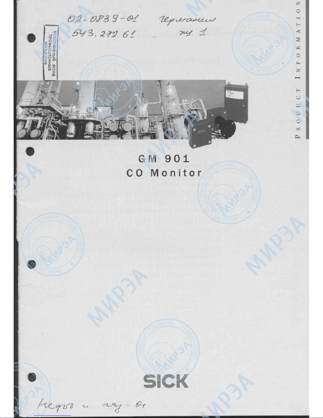
GM
901
CO
Monitor
Н
О
£
р
о
05
SICK
Page 2
GM
901
Introduction
Product
Information
Introduction
Conformities
^
Conforms
to
EMC
specifications pursuant
to EN
50081-1/EN
50082-2
^
CE
certification pursuant
to EC
Guideline
EMC
89/336
EWG and
NSP
72/23/EWG
*•
VDE
Guidelines pursuant
to EN
61010
(IEC
1010-1,
VDE
0411),
class
of
protection
1,
degree
of
protection
IP 65
^
Prototype
tested
by
TUV,
Report
No.
502/0741/96-20
081 751
*•
SICK
AG
Environmental Monitoring
is
certified
to ISO
9001.
Purpose
of
this
Document
This
"Product Information" describes
all of the
procedures required
to
mount
and
install
the GM
901.
The
document
is
intended
to
help
you
plan
your
project
and
prepare
the
meas-
uring point before
the
device
is
delivered.
Among
other things,
the
document contains important information
on:
>•
Areas
of
application
of the GM 901
^-
Features
^
Input
and
output
options
>•
Installation instructions
for
project planning
and
mounting
the GM 901 at the
measuring point
^-
Prerequisites
for
mounting
and
connecting
the
device
>•
Overview
of the
installation activities
^-
Calibrating
the
system
(zero
calibration)
^-
Overview
of the
technical
data
and
dimensioned
drawings
of the GM 901
components
8 008
876/07-99.HJS.SM • SICK
AG •
Environmental
Monitoring • Germany
• All
rights
reserved
Page 3
F
GM
901
Contents
Product
Information
Contents
1
Overview
.....................................................
4
1.1
Benefits
of the
GM
901
......................................
4
1.2
Applications
................................................
4
1.3
Standard
Components
.......................................
5
1.4
Accessories/Options
.........................................
6
1.4.1
Accessories
for the GM 901
...........................
7
1.4.2
Options
..............................................
8
2
Instructions
for
Project Planning
................................
9
2.1
Checklist
...................................................
9
2.2
Installation Sequence
.......................................
10
3
Preparations
for
Installation
..................................
.11
3.1
Preparations
for
Mounting
..................................
11
3.1.1
Installation Proposal
..................................
11
3.1.2
Instructions
for
Mounting
the
Flange with Pipe
...........
11
3.1.3
Installation
on
Steel Ducts
............................
12
3.1.4
Installation
on
Brick Ducts
.............................
12
3.1.5
Installation
on
Thin-Walled Ducts
.......................
12
3.1.6
Auxiliary Pipe
for
Measuring
Paths
of
Less
than
2m
......
13
3.1.7
Aligning
the
Flange with
the
Optical Alignment
Aid
.........
13
3.2
Preparations
for
Electrical Installation
.........................
14
3.2.1
Wiring Specifications/Interfaces
to the
Evaluation
Unit
.....
14
3.2.2 Connection Unit (Accessory)
...........................
15
3.2.3 Purge-Air Unit (Option)
................................
16
4
Preparations
for
Startup
.....................................
.17
4.1
Zero
Calibration
............................................
17
4.2
SPAN
Test (Option)
.........................................
17
4.2.1 Test
Cells
...........................................
17
4.2.2 Calculating
the
Test Values
............................
18
5
Technical Data
.............................................
.19
5.1
Device Data
...............................................
19
5.1.1
Accessories
.........................................
20
5.1.2
Options
.............................................
20
5.2
Dimensioned Drawings
......................................
21
5.2.1
Transmitter
and
Receiver
.............................
21
5.2.2 Evaluation Unit
......................................
22
5.2.3
Purge-Air
Unit
........................................
23
5.2.4
Air
Filter Assembly
...................................
23
P
8 008
876/07-99.HJS.SM • SICK
AG •
Environmental Monitoring • Germany
• All
rights reserved
Page 4
GM
901
Overview
Product
Information
тттттнвияяитвтттяятшттвнияаятш£:
_____________тт!т1штттшпттттттттттмтяштттттишшят
1
Overview
l.±
Benefits
of the
GM
9O1
^-
CO
analyzer:
GM 901
measures
the CO
content directly
in the gas
duct.
^
Bus
capability: using
a CAN
bus,
the
evaluation unit
can be
mounted
at a
distance
of up to
1000 m from
the
measuring point, e.g.
in the
control room.
^-
Easy
to
mount
and
connect.
>
Short startup time
- to
install
the
optical units
and
switch
on the
power supply.
^-
User-friendly
operation
by
means
of
function
buttons
on the
evaluation
unit:
- for
settings
the
display
and
output functions
- for
configuring
the
device parameters
^
Low
maintenance
requirements,
no
test
gases
required.
*•
Variable measurement value output:
ppm,
mg/m3,
or
mg/Nm3.
^
Measurement value, measuring range,
and
limit values
are
visible
on the
display.
Additional temperature display
and
plain text information
on the
operating mode.
>
Integrated diagnosis function. Diagnosis data
can be
called
up for
warnings
and
error messages.
±.2
Applications
The
GM 901 is
designed
for
instant
and
no-contact monitoring
of the CO
concen-
tration,
for
example,
for
process control purposes
in the
following areas:
^-
Power stations
>
Coal
processing plants
^-
Refuse incineration plants
^
Plants
in the
cement industry
>•
Paper industry
^-
Pharmaceutical industry
>
Melting/steel
industry
^
Glass industry
^
Chemical industry
^
Food industry
8 008
876/07-99.HJS.SM • SICK
AG •
Environmental
Monitoring • Germany
• All
rights
reserved
Page 5
GM901
Overview
Product
Information
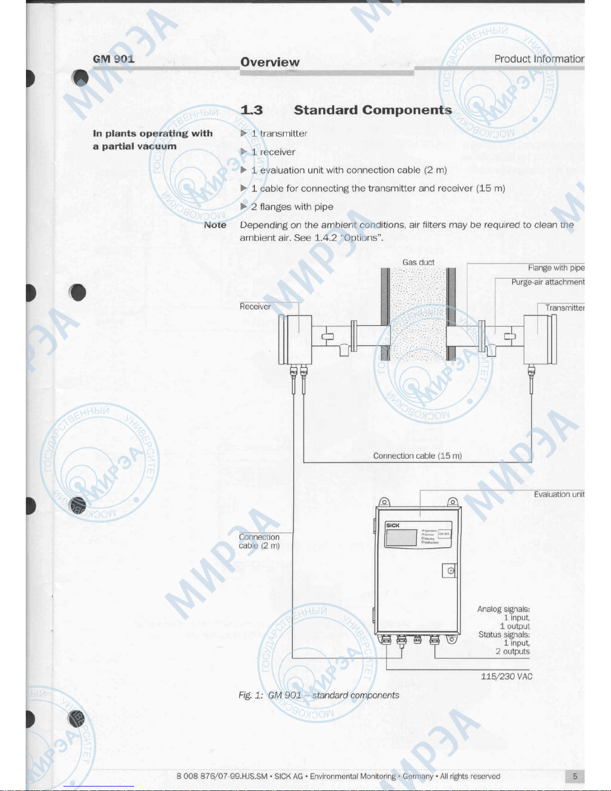
In
plants
operating
with
a
partial
vacuum
±.3
Standard Components
>• 1 transmitter
^ 1 receiver
^ 1 evaluation unit with connection cable
(2
m)
> 1 cable
for
connecting
the
transmitter
and
receiver
(15 m)
^- 2 flanges
with pipe
Note
Depending
on the
ambient
conditions,
air
filters
may be
required
to
clean
the
ambient air.
See
1.4.2 "Options".
Gas
duct
Connection
cable
(2 m)
Connection cable
(15 m)
©
Fig.
1:
GM
901 -
standard
components
Flange with pipe
L
Purge-air attachment
Л
Transmitter
Evaluation unit
Analog signals:
1
input,
1
output
Status
signals:
1
input,
2
outputs
115/230
VAC
8 008
876/07-99.HJS.SM • SICK
AG •
Environmental Monitoring • Germany
• All
rights reserved
Page 6
GM901
Overview
Product
Information
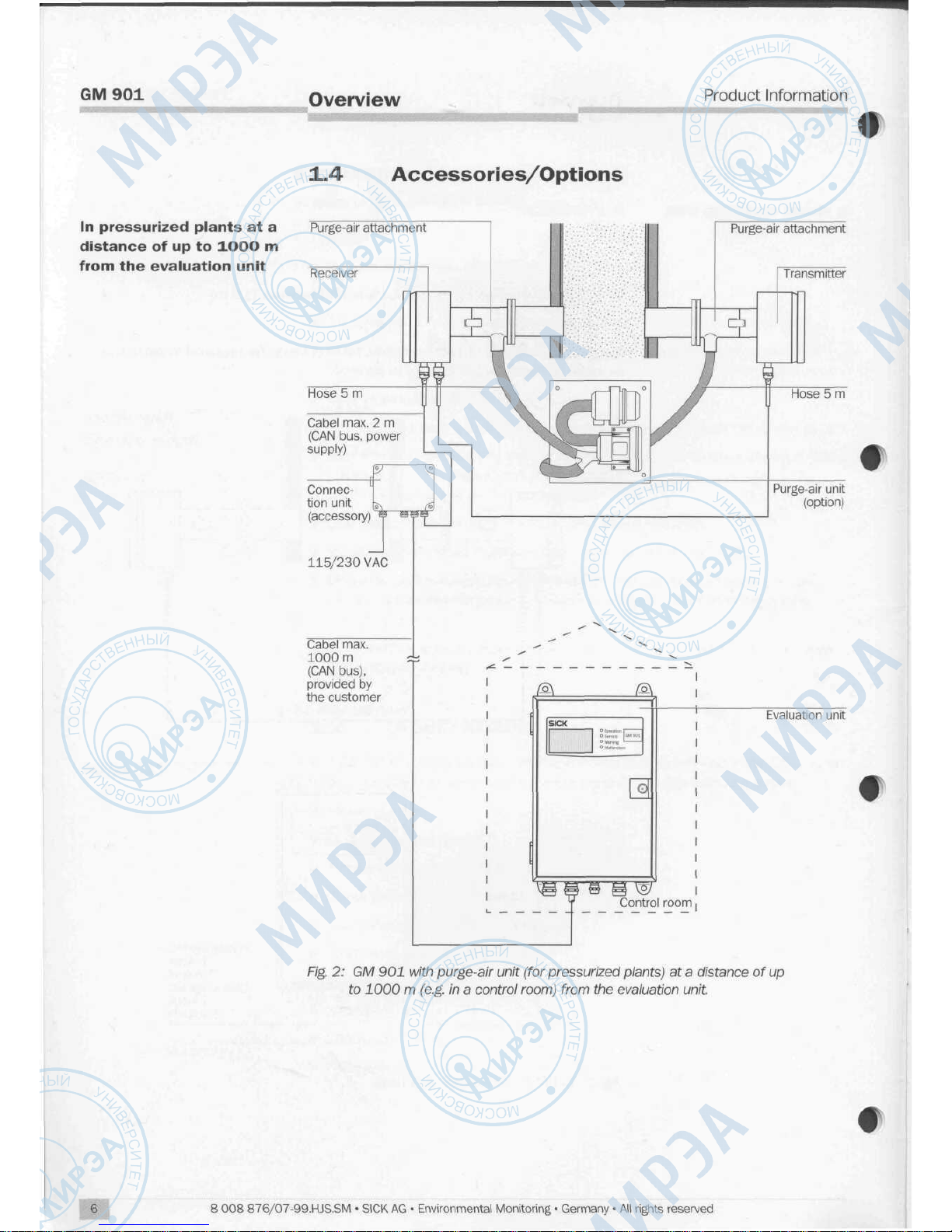
In
pressurized plants
at a
distance
of up to
±OOO
m
from
the
evaluation unit
±.4
Accessories/Options
Purge-air
attachment
Receiver
A
У
г
Purge-air
attachment
A
Transmitter
Hose
5 m
Cabel
max.
2 m
(CAN
bus,
power
supply)
Connec-
tion unit
(accessory)"
115/230
VAC
Purge-air unit
(option)
Cabel
max.
1000m
(CAN
bus),
provided
by
the
customer
©
Control
room
Evaluation
unit
f
Fig.
2: GM 901
with purge-air unit (for pressurized plants)
at a
distance
of up
to
1000 m (e.g.
in a
control room) from
the
evaluation unit.
8 008
876/07-99.HJS.SM • SICK
AG • Environmental Monitoring • Germany
• All
rights reserved
Page 7
GM901
Overview
Product
Informatior
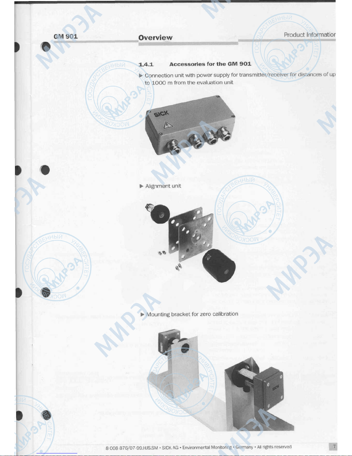
1.4.1
Accessories
for the
GM
9O1
Connection unit with power supply
for
transmitter/receiver
for
distances
of up
to
1000 m from
the
evaluation
unit
Alignment
unit
Mounting
bracket
for
zero
calibration
8 008
876/07-99.HJS.SM • SICK
AG •
Environmental
Monitoring • Germany
• All
rights
reserved
Page 8

GM901
Overview
Product
Information
f
Cover
plate with seal
for
covering
the
duct apertures when
the
transmitter
and
receiver
are
replaced
CO
test
cell with bracket
in
transport case
Weatherproof
covers
for
mounting
the
device outdoors
Dimensioned
Drawings,
Page
21
1.4.2
Options
Purge-air
unit
for
protecting
the
optical boundary areas
on the
transmitter
and
receiver
from dirt (including connection hose)
-
Air
filter
assembly
for
cleaning
the
ambient
air in
plants operating with a partial
vacuum
PT
100
temperature sensor including measuring transducer
f
8 008
876/07-99.HJS.SM • SICK
AG •
Environmental
Monitoring • Germany
• All
rights
reserved
Page 9

GM901
Instructions
for
Project
Planning
Product
Informatior
2
Instructions
for
Project
Planning
2.±
Checklist
See
also Chapter 3 "Preparations
for
Installation".
Check
the
following conditions
by
ticking
the box in the
third column.
I
Check
Measuring
point
selection
Field
service
!
conditions
Flange
mounting
(see
3.1
"Preparations
for
Mounting")
!
Mounting
location
Transmitter
and
receiver
Duct walls
Evaluation
unit
(see
3.1.1.
"Installation
Proposal")
Duct
aperture
selection
Installation
site
Tab.
1:
Checklist
(contd.
on
Page
10)
Measure
The
gas flow in the
vicinity
of the
measuring point
should
be
homogeneous.
Measuring
gas
temperature: s 300
°C;
higher temperatures
on
request.
Dust concentration:
< 1
g/m3 x m
A
high dust content
in the gas
duct
can
impair
the
measurement.
Duct
pressure:
• A
purge-air
unit
is not
required
if
there
is a
constant partial vacuum
in the
duct.
Air
filter
set
recommended.
• A
purge-air unit
is
required
in
pressurized
plants. Please consult
the
SICK
Customer
Service department with regard
to the
correct
fan
type.
Steel ducts:
the
device
is
designed
for
installation
in
steel
ducts.
Brick
or
thick-walled ducts: modified
flange
with
pipe
required.
Can be
provided
by the
customer
or
designed
by
SICK.
Suitable reinforcements
or
support constructions
must
be
provided
on
thin-walled ducts
to
ensure
that
the
transmitter
and
receiver
are
permanently
aligned.
The
size
and
position
of the
aperture must
be
sel-
ected
in
such
a way
that sufficient space
is
pro-
vided
for the
transmitter
and
receiver.
Some
of the
duct insulation must
be
removed
and
sufficient space provided
for
installation
and
maintenance activities.
If the
device
is
mounted outdoors, sufficient space
should
be
provided
for the
weatherproof
cover.
The
unit
should
be
installed
at a
position
that
is
freely accessible. Max. distance from transmitter
and
receiver:
-
standard:
2 m
-
with extension cable:
17 m
-
For
cable
lengths
up to
1000
m:
with
connection unit (accessory)
The
unit should
be
mounted
on a flat
surface.
п
п
In
8 008
876/07-99.HJS.SM • SICK
AG •
Environmental
Monitoring • Germany
• All
rights
reserved
Page 10

GM901
Instructions
for
Project
Plannmg
Product
Information
Purge-air
unit
(option)
Mounting
platform
Check
Measure
Installation site
!
Ambient conditions
Installation
Accident
prevention
Tab.
1:
Checklist
The
purge-air supply must
be
installed
at an
equal
distance
from
the
transmitter
and
receiver
to
ensure that
the air flows
uniformly.
Sufficient space should
be
provided
for
replacing
the filter set and
dust collector.
If
the
unit
is
mounted outdoors, sufficient space
should
be
provided
for
installing/removing
the
weatherproof
cover.
The
temperature
of the
purge
air
entering
the
duct
must
not
fall below
the dew
point.
If
neces-
sary,
the
purge
air
must
be
heated
(SICK
heaters
are
recommended).
"temperature"of
the
intake
air:"6~°C"<~T
< 55
°C.
If
Т < О °С,
heat
the
purge air.
The
intake purge
air
should
be
free
of
dust.
П
-
Height
of
platform: approx.
1.5 m below
the
inten-
ded
location
for the
transmitter
and
receiver.
-
Lighting
and a
power supply should
be
installed
at
the
measuring point
to
facilitate servicing.
All
of the
device
components
should
be
safely
accessible.
Always
observe
the
national accident prevention
regulations!
П
2.2
Installation
Sequence
1.
Step:
Carry
out all of the
planning
activities
(see
2.1
"Checklist")
2.
Step:
Mount
the flange for the
transmitter
and
receiver
at the
measuring
point
3.
Step:
Check
the
wiring
at the
site using
the
wiring specifications (see
3.2.1 "Wiring Specifications/Interfaces
to the
Evaluation
Unit")
4.
Step:
Lay the
cables
and
signal leads
5.
Step:
Check
all the
connections (see
3.2
"Preparations
for
Electrical
In-
stallation")
6.
Step:
In
pressurized plants: mount
the
(optional) purge-air unit
and
check
whether
it is
functioning correctly
7.
Step:
Mount
the
evaluation unit
8.
Step:
Mount
the
transmitter
and
receiver
9.
Step:
If the
cable between
the
receiver
and
evaluation unit
is
longer than
17 m:
install
the
connection unit (accessory)
10.
Step:
If the
devices
are
installed outdoors: mount
the
weatherproof
covers
f
10
8 008
876/07-99.HJS.SM • SICK
AG •
Environmental Monitoring • Germany
• All
rights reserved
Page 11

GM901
Preparations
for
Installation
Product
Informatior
3
Preparations
for
Installation
3.1
Preparations
for
Mounting
3.±.1
Installation
Proposal
HI——Measuring
distance-—
Flange-flange
Flange
with
pipe
ArrangementX
~|ч
of
stud bolts x«4Fi
(shown
rota-
ted
through
45°)
Steel
pipe
50x5
DIN
2391
(Mounting
position
marking
Fig.
3:
Installation
proposal
for GM 901
with
mounting
flange
and
purge-air
unit
(optional)
3.1.2
Instructions
for
Mounting
the
Flange
with
Pipe
In
the
description that
follows,
the
term
"flange"
is
used
to
refer
to the flange
with
pipe
The
standard
flange
supplied
by
SICK
has a
total length
of 130 mm and an
oute
diameter
of 76 mm.
>
Mount
the flange in
such
a way
that
the
axes
are
aligned.
The
angular dis-
placement must
be
less than
1°.
Suitable reinforcements
or
support
construe
tions must
be
provided
on
thin-walled ducts.
>
The
pipe stubs
on the flange
should protrude into
the
duct
by
approx.
30 mm
The
pipe stubs must also
be
adapted
if
necessary.
^ A suitable auxiliary pipe
can be
used
to
align
the
flange
for
measuring dis-
tances that
are
easily accessible
(up to 2 m).
(The inner diameter
of
standarc
flanges
is
70.2
± 1
mm.)
>
The
optical alignment
aid
(accessory) must
be
used
for
longer measuring
patl
or
measuring paths that
are
difficult
to
access.
8 008
876/07-99.HJS.SM • SICK
AG •
Environmental Monitoring • Germany
• All
rights reserved
11
Page 12

GM901
Preparations
for
Installation
Product
Information
3.1_3
Installation
on
Steel
Ducts
1=130,240,
or
500mm
Mounting
position marking
Arrangement
of
stud
bolts
(shown
rotated
through 45°)
Fig.
4:
Steel
duct
30
3.1.4
Installation
on
Brick
Ducts
On
brick ducts,
the
flange must
be
welded
to a
suitable retaining plate (provided
by
the
customer) mounted
on the
duct.
500mm
Mounting position marking
^Т^ТоГ^ч.
j^
1
"*")
^^.
/^Ж^^^^^У\
У'~"
<
-<_v> /
/
Arrangement
of
\
stud bolts
\
(shown
rotated
Vati
through
45°)
*ЦЩ
$~
k
J
1
—
i
h
E3
^
-
-^
\
у
у
Q
«.
^
С
Sl^
X™
aua'i
30
(0
5:
Brick
duct
3.±.5
Installation
on
Thin-Walled
Ducts
On
thin-walled ducts
or at
locations subject
to
vibrations, reinforcement must
be
provided
in the
form
of
junction plates.
Mounting
position marking
12
Fig.
6:
Junction plates
8
008
876/07-99.HJS.SM • SICK
AG •
Environmental
Monitoring • Germany
• All
rights
reserved
Page 13

GM901
Preparations
for
Installation
Product
Information
3.3-6
Auxiliary Pipe
for
Measuring
Paths
of
Less than
2 m
An
auxiliary pipe should
be
used
to
help mount
the
standard flange.
I
Fig.
7:
Mounting
the
flange with
an
auxiliary pipe
*
Arrangement
of
stud
bolts
(shown
rotated
through 45°)
3.1.7
Aligning
the
Flange
with
the
Optical
Alignment
Aid
A
suitable auxiliary pipe
can be
used
to
align
the flange for
measuring paths that
are
easily accessible
(up to 2 m).
(The inside diameter
of
standard
flanges is
70.2
± 1
mm.) When using
the
optical alignment aid, align
the
light source
and
the
adjustment
tube
as
shown
in the figure
below.
I
Light
source
Flange
1
О
Flange 2 Adjustment tube
Fig.
8:
Mounting
the
flange with
the
optical alignment
aid
*
Arrangement
of
stud bolts
(shown
rotated
through 45°)
Note
When carrying
out the
zero calibration, make sure that
the
mounting bracket
is
installed
at a
distance equal
to the
(flange-flange)
measuring path.
^-
Align
flange 1 in
such a way
that
the
light spot from
the
light source
is
centered
on
the
target
of the
adjustment tube. Tack-weld
flange 1.
^-
Place
the
adjustment
aid on flange 2.
*•
Align
and
tack-weld
flange 2.
8 008
876/07-99.HJS.SM • SICK
AG •
Environmental
Monitoring • Germany
• All
rights
reserved
13
Page 14

GM901
Preparations
for
installation
Product
Information
SICK
О
Operation 1 —————
О
Service
GM
901
O
Warning ' —————
О
Malfunction
3.2
Preparations
for
Electrical Installation
All
installation
and
final wiring activities must
be
carried
out by the
customer,
un-
less otherwise agreed with SICK.
3.2.1
Wiring Specifications/Interfaces
to the
Evaluation Unit
The
conductor
and
jacket material
as
well
as the
insulating coverings must
be
selected
in
accordance with
the
conditions
at the
site.
Analog
out
Digital
out
0...20
mA 48 V
AC/DC
100
Digital
in
30VA.1A
max.
5 V/2 mA
CAN
bus
Temp. Maintenance
CO
Malfunction Limit value
Power
supply
Inputs
and
outputs
CAN
bus
interface
Power
supply
Temperature input
3
wires; cross-section:
0.75
to 2.5
mm
2
Cable
diameter:
6 to 12 mm
Conduit
thread
13.5
CAN
bus
interface
Inputs
and
outputs
Max.
bus
length:
1000
m
Wires:
2x2
plus shield; cross-section:
up
to 500 m
>
0.25
mm2,
up to
1000
m
>
0.75
mm
2
Cable
diameter:
6 to 10 mm
Conduit
thread
12
Digital input, active
<;
500
Q,
relay
Analog output
0 to 20 mA,
max.
load
500
Q
Outside
diameter
of
cable:
6 to 12 mm
Conduit thread
13.5
Temperature input
Analog
input
0 to 20 mA;
sense resistor
100
Q
2
wires plus shield
Outside
diameter
of
cable:
4 to 8 mm
Conduit
thread
9
Fig.
9:
Cable specifications
and
interfaces
to the
evaluation unit
8
008
876/07-99.HJS.SM • SICK
AG •
Environmental
Monitoring • Germany
• All
rights
reserved
Page 15

GM901
Preparations
for
Installation
Product
Information
,
t
3.2.2
Connection
Unit
(Accessory)
The
connection unit
is
required
to
connect
the
evaluation unit
and
receiver
over
distances
> 17
m.
The
unit provides
the
power supply
to the
sensors
and
con-
nects
the CAN
bus.
The
connection unit
is
mounted
at the
receiver with a standard
2 m
cable.
When installing
the
connection unit, disconnect
the
power supply
to the
receiver
at
the
evaluation unit
and
connect
it to the
connection unit.
Operating
voltage
setting
115
V/230
V
230
V
=
or
P^/N/LL
Fuse
2.5
ДГ
1
'
250V
Connection
to
Connection
to
evaluation
unit
GM 901
receiver
Power
supply
CAN
bus
interface
i t
Power
supply
115
V/230
V AC
Conduit thread 13.5
CAN
bus
interface
(Connection
to
evaluation unit)
Max.
bus
length 1000
m
Wires:
2x2
plus
shield,
cross-section:
up
to 500 m
a
0.25
mm2,
up to
1000
m
Cable
diameter:
6 to 10 mm
Conduit thread 13.5
0.75
mm
2
t
Fig.
10:
Connection
unit
8 008
876/07-99.HJS.SM • SICK
AG •
Environmental
Monitoring • Germany
• All
rights
reserved
15
Page 16

GM901
Preparations
for
Installation
Product
Information
Power
supply
3.2.3 Purge-Air
Unit
(Option)
The
three-phase a.c. motor
of the
type
2BH1300
fan is
connected
to the 3 L-
conductors
LI,
L2, and L3. The
rated voltage
of the
motor
in the
running connec-
tion
must
be
equal
to
that
of the
phase-to-phase
voltage
of the
system
(oper-
ating
voltage).
Motors with a winding construction
for 230 V
(A)/400 V (Y)
can be
used
if
they
are
started directly
and if a
suitable circuit
is
provided
on the
terminal board
for
230 V or 400 V.
U2
V1
W2
W1
V
IE
/2
U2 V
I
ft,
1
Ivi
?PE
Low
pressure monitor
W2
U2 V2
q~
_n
nU1О
V1
о
W1
о
РЕ
L1
L2
L3
РЕ
L.
Й
24V
Fig.
11:
Electrical connections
of the
purge-air unit
16
8 008
876/07-99.HJS.SM • SICK
AG •
Environmental Monitoring • Germany
• All
rights reserved
Page 17

GM
901
.___
_
Preparations
for
Startup
Product
Information
4
Preparations
for
Startup
•
4.1
Zero
Calibration
A
zero calibration must
be
carried
out on the GM 901
before
the
device
is put
into operation
for the
first
time
or
before
it
resumes operation.
A
СО-free environment
is
required
for the
zero calibration.
The
calibration
can
also
be
carried
out
directly
at the
measuring
point
if the
plant
is
shut
down
and
the
duct
is
free
of CO.
If a
zero calibration
is not
possible
at the
measuring point,
it
must
be
carried
out
with
the
transmitter
and
receiver
at the
mounting brackets.
Optical
axis
Reveiver
Mounting
bracket
Transmitter
Mounting
bracket
-Level
surface :„
Fig.
12:
Mounting
bracket
(accessory)
for
zero
calibration
Note
If
purge-air attachments
are
also used
on the
mounting brackets,
the
transmitter
and
receiver should
be
attached using
the
quick-release locks.
i
•
4.2
SPAN Test (Option)
4.2.1
Test
Cells
The
following
test
cells
are
available
^
250
ppm
x
m
^
750 ppm x m
^
4000
ppm x m
^
10000
ppm
x m
Other concentrations
can
also
be
supplied
on
request.
8 008
876/07-99.HJS.SM • SICK
AG •
Environmental
Monitoring • Germany
• All
rights reserved
Page 18

GM
901
Preparations
*or
Startup
Product Information
4.2.2
Calculating
the
Test
Values
The
test
concentration (test cell value)
is
calculated using
the
following
formula*:
TV
[ppm
x
m]
= MR
[ppm]
x x x S
[m]
TV = Test value
MR = Upper measurement range limit
x = Position
of the
test
point
S = Measuring distance
Example:
Upper
measuring range limit
MR = 1500
ppm
Measuring distance
S =
4m
Test point
at 70% of MR x= 0.7
TV
[ppm
x m] = MR
[ppm]
x x x S [m]
TV
[ppm
x m] =
1500 [ppm]
x 0.7 x 4 [m]
TV
[ppm
x m] =
4200
[ppm
x m]
The
test
cell value should
be
4200
ppm x m.
The
nearest
test
cell
has the
test
value
4000
ppm x m.
* If the
concentration values
are in
mg/m3,
they
must
be
converted accordingly.
18 8 008
876/07-99.HJS.SM • SICK
AG •
Environmental Monitoring • Germany
• All
rights
reserved
Page 19

GM901
Technical
Data
Product
Information
5
Technical
Data
5.1
Device
Data
Basic
device
Transmitter
Receiver
Evaluation
unit
I •
Measurement range
Measuring
distance
Gas
temperature
Linearity
Resolution
Adjustment time
Ambient
temperature
Degree
of
protection
Voltage
supply
Line
frequency
100 ppm to
20000
ppm*________
0.5 m to 8
m
300
°C;
higher
temperatures
on
request
± 5% of
upper measurement range limit
approx.
10 ppm
~5
to
360 s ~
^20
°C
to
+55
°C
IP
65
115/230
V
~50/60'Hz
75
VA
Max.
power consumption
Dimensions
incl.
purge-air
attachment
Weight incl. purge-air attachment
3 kg
Lamp
service life
Dimensions incl. purge-air
attachment
240 mm x 150 mm x 150 mm (L x W x H)
approx.
20000
hours
240 mm x 150 mm x 150 mm (L x W x H)
Weight
incl. purge-air attachment
3 kg
Analog
input
Analog
output
electrically
isolated
Relay
1
0 to 20
mA;
input resistor
100
Q
~0
to~20~mA;
maxJoad
500
Q
Break
contact
for
device malfunction, floating,
make contact
Max.
switching current:
1 A
Max.
switching voltage:
125 V DC
150 V AC
Max.
switching capacity:
30 VA DC
60 VA AC
Relay
2
Make
contact
for
limit value violation
Max.
switching current:
1 A
Max.
switching voltage:
125 V DC
150 V AC
Max.
switching capacity:
30 VA DC
60 VA AC
Status
input
Serial
interface
Dimensions incl. purge-air
attachment
Status
input
for
maintenance
Max.
contact
load:
5 V/2 mA
~RS
232 for
service
CAN
bus
(option)
Profi-bus
(option)
200 mm x 90 mm x 300 mm (L x W x H)
Weight
incl. purge-air attachment
4.3 kg
Tab.
2:
Technical
data
*
Depending
on the
measurement
distance
8 008
876/07-99.HJS.SM • SICK
AG •
Environmental
Monitoring • Germany
• All
rights
reserved
19
Page 20

GM901
Technical
Data
Product
Information
5.1_±
Accessories
Part
Optical
alignment
aid
Mounting bracket
for
zero-point
adjustment
Connection unit with
230
V/24 V power supply
for
transmitter
and
receiver
5 m
extension cable
10 m
extension cable
15 m
extension cable
Weatherproof cover
for
purge-air unit
Weatherproof cover
for GM 901
transmitter/receiver
Weatherproof cover
for GM 901
evaluation unit
Cover
plate
with seal
Air
filter assembly
Test case
for
SPAN
test
with cell
Quantity
1
2
1
1
2
1
2
1
1
Order
number
2020436
2020445
2020440
2020437
2020438
2020439
5306108
2702407
4029146
2020435
2020442
2019639
Tab.
3:
Accessories
5.1.2
Part
Options
Quantity
Order
number
Purge-air
unit
with
distributor
and 5 m
hose
Flange with pipe
130 mm, ST 37
Flange with pipe
240 mm, ST 37
Flange
with pipe
500 mm, ST 37
Flange with pipe
130 mm,
1.4571
Flange with pipe
240 mm,
1.4571
Flange with pipe
500 mm,
1.4571
Temperature sensor
PT 100
incl.
measuring transducer
Tab.
4:
Options
1
1
1
1
1
1
1
1
1012424
2017845
2017847
2017849
2017846
2017848
2017850
6007585
20
8 008
876/07-99.HJS.SM • SICK
AG •
Environmental
Monitoring • Germany
• All
rights
reserved
Page 21

I
GM901
I •
за
Technical
Data
5.2
Dimensioned Drawings
5.2.1 Transmitter
and
Receiver
240
80
Fig.
13:
Dimensions
of
transmitter
and
receiver
Product
Information
>
492
239
Fig.
14:
Dimensions
of
weatherproof cover
for
transmitter
and
receiver
8
008
876/07-99.HJS.SM • SICK
AG •
Environmental Monitoring • Germany
• All
rights reserved
Page 22

GM901
Technical Data
Product
Information
5.2.2 Evaluation Unit
200
SICK
160
osevfce
,
OWming
<—
OMalfunctkxi
о
0
ro
ro
CM
97.5
Г 90
f
82
I
I
*И
-г
—
'
Fig.
15:
Dimensions
of
evaluation unit
--—-—-—-—-—e-
(239)
184
19
0
(O
CM
CM
190
Fig,
16:
Dimensions
of
weatherproof cover
for
evaluation unit
8
008
876/07-99.HJS.SM • SICK
AG •
Environmental Monitoring • Germany
• All
rights reserved
Page 23

GM901
Technical
Data
Product Information
5.2.3 Purge-Air Unit
Fig.
17:
Dimensions
of
purge-air unit
255
550
605
F/g.
18:
Dimensions
of
weatherproof cover
for
purge-air
unit
5.2.4
Air
Filter Assembly
I •
Air
filter
^
Mounting holes
15.5
x
7
•«—
1
f-
f
?
/
\
-—
—
•
—
'A
—
17
———
35
————
-
5
———
-
\
H
1
"t
-^r
Hose connector
+
——— 0 188 ——
1
•
0
4
,——
,
ч
———
0
/
1_:=^
154
—
«•
\
\
———
=
___
Ш
040
0158-
Fig.
19:
Dimensions
of the air
filter
assembly
8
008
876/07-99.HJS.SM • SICK
AG •
Environmental Monitoring • Germany
• All
rights reserved
Page 24

Argentina
Phone
+54
114555
0055
Fax
+54
114555
0444
Australia
Phone
+61 3
9497
4100
(0
08) 33 48 02 -
toll
free
Fax
+61 3
9497
1187
Austria/Slowenia
Phone
+43 22 36 62 28 8-0
Fax
+43 22 36 62 28 85
BeNeLux
Netherlands
Phone
+31 73 599 50 44
Fax
+31 73 599 47 18
Belgium/Luxembourg
Phone
+32 9
2240
394
Fax
+32 9
2235
645
Brazil
Phone
+55 11
50311622
Fax
+55 11
5031 5176
Canada
Phone
+01
(905)
771-1444
+01
(905)
771-1415
Fax
+01
(905)
771-1616
Chile
Phone
+56
2-274
7430
Fax
+56
2-204
9338
China/Hongkong
Phone
+86 21
6485
4767
Fax
+86 21
6485
0938
Croatia/Slovenia
Phone
+3 85
1-363
3055
Fax
+3 85
1-363
3033
Cyprus
Phone
+35 72 49 43 00
Fax
+35 72
3113
62
Czech
Republic
Phone
+42 02 578 10 561
Fax
+42 02 578 10 559
Denmark
Phone
+45
4390 8611
Fax
+45
4369 1340
Egypt
Phone
+202
361
2747
Fax
+202
360
8258
Finland
Phone
+358
97 55 66 11
Fax
+358
97 55 32 97
France
Phone
+33 1 64 62 35 00
Fax
+33 1 64 62 35 77
Germany
Phone
+49 76
4146
90
Fax
+49 76
4146
91149
Phone
+49 75 32
801-0
Fax
+49 75 32
801-104
The
newly formed German
states
Phone
+49 35 20 55 24 10
Fax
+49 35 30 55 24 50
Great
Britain/Ireland
Phone
+17 27 83 11 21
Fax
+17 27 85 67 67
Greece
Phone
+30 16 74 74 64
Fax
+30 16 74 11 59
Hungary
Phone
+36 1-3 80 60 20
Fax
+36 1-2 30 86 98
India
Phone
+91 2 24 93 84 03
Fax
+91 2 24 93
0191
Israel
Phone
+97 29 74 12 657
Fax
+97 29 97 42 419
Italy
Phone
+39
Oil
2 23 66 01
Fax
+39
Oil
2 23 66 09
Japan
Phone
+813
5444-0929
Fax
+8135444-0938
Korea
Phone
+82234448781
Fax
+82 2
3444
7945
Lebanon
Phone
+96
1188
50 61
+96
11 89 07 10
Fax
+96 11 88 50 61
+96
11 89 07 10
Mazedonia
Phone
+38 9 91 29 66 66
Fax
+38 9
9113
33 02
Mexico
Phone
+52 55 63
8188
Fax
+52 56 11 00 03
New
Zealand
Phone
+64 9 415
0459
Fax
+64 9 415
0465
Norway
Phone
+47 63 87 02 00
Fax
+47 63 87 02 01
Pakistan
Phone
+92 25 65 985
Fax
+92 21 25 66 059
Poland
Phone
+48 2 26 44 83 45
Fax
+48 2 26 44 83 42
Portugal
Phone
+351
234 303 900
Fax
+351
234 303 910
Russian Federation
Phone
+70 95 275 22 73
+70 95 275 29 73
+70 95 275 75 63
Fax
+70 95 279 67 76
Romania
Phone
+40 (0) 1 687 34 62
Fax
+40 (0) 1 242 68 24
Singapore/Malaysia/Thai
land
Indonesia/Phillippines
Phone
+65 744 37 32
Fax
+65 841 77 47
Slovac Republic
Phone
+4 21 75 44 34 089
Fax
+4
2175
44 14 964
South Africa
Phone
+27
11455
3809
+27
11455
3816
Fax
+27
11455
4668
Spain
Phone
+34 93 48 03 10 6
+34
91 64 26 112
Fax
+34 93 47 34 46 9
+34
92 64 26 112
Sweden
Phone
+46 8 632 30 00
Fax
+46 8 632 32 99
Switzerland/Liechtenstein
Phone
+4141
612 17 00
Fax
+4141612
17 01
Taiwan
Phone
+8 86
2-8797-1981-6
Fax
+8 86
2-2799-0272
Turkey
Phone
+90 312 435 06 94
Fax
+90 312 435 19 83
United Arabian Emirates
Phone
+97
14-324
75 00
Fax
+97
14-324
25 00
USA
Phone
+1
(952)
941
6780
Fax
+1
(952)
941
9287
SICK
SICK
AG •
Environmental
Monitoring • Nimburger
Str.
11 •
D-79276
Reute • Germany
Phone
+49
76414
69-0 • Fax
+49
7641 4 69-11
49 •
http://www.sick.de
 Loading...