

Page 1

GM700 Ex
Laser Gas Analyzer,
Version with Measuring Probe
O P E R A T I N G I N S T R U C T I O N S
Page 2

Described product
GM700 Ex
Probe version
Version GM700-05, GM700-09
Manufacturer
SICK AG
Erwin-Sick-Str. 1
79183 Waldkirch
Germany
Production location
SICK AG
Nimburger Str. 11 · D-79276 Reute · Germany
Legal information
This work is protected by copyright. Any rights derived from the copyright shall be
reserved for SICK AG. Reproduction of this document or parts of this document is only
permissible within the limits of the legal determination of Copyright Law. Any modifica‐
tion, abridgment or translation of this document is prohibited without the express writ‐
ten permission of SICK AG.
The trademarks stated in this document are the property of their respective owner.
© SICK AG. All rights reserved.
Original document
This document is an original document of SICK AG.
2
O PE R AT I NG IN S TR U CT I ON S | GM700 Ex 8019532/100Q/V1-1/2018-08 | SICK
Subject to change without notice
Page 3

Contents
CONTENTS
1 About this document........................................................................ 7
1.1 Function of this document....................................................................... 7
1.2 Scope of application................................................................................. 7
1.3 Target groups (and document structure)................................................. 7
1.4 Further information................................................................................... 7
1.5 Data integrity............................................................................................. 7
1.6 Symbols and document conventions...................................................... 8
1.6.1 Warning symbols...................................................................... 8
1.6.2 Warning levels / Signal words................................................. 8
1.6.3 Information symbols................................................................ 9
2 Safety information............................................................................ 10
2.1 Main operating information..................................................................... 10
2.2 Warning information on the device.......................................................... 13
2.3 Intended use............................................................................................. 14
2.3.1 Purpose of the device.............................................................. 14
2.4 Responsibility of user............................................................................... 14
3 Product description........................................................................... 16
3.1 Product identification............................................................................... 16
3.2 Product characteristics............................................................................ 16
3.3 Type plate.................................................................................................. 16
3.4 Device variants......................................................................................... 17
3.5 Pressure and temperature sensor........................................................... 17
3.6 Options...................................................................................................... 17
3.7 Layout and function.................................................................................. 17
3.7.1 Function of the pressurized enclosure................................... 18
3.8 Purge air unit............................................................................................. 18
3.9 Check cycle............................................................................................... 19
3.10 Explosion protection in accordance with ATEX....................................... 20
3.10.1 Operation in potentially explosive atmosphere...................... 20
3.10.2 Zone of use GM700 Ex 3G components................................ 21
3.10.3 Pressurized enclosure system................................................ 22
3.10.3.1 Safety functions...................................................... 22
3.11 Sender/receiver unit - evaluation unit connecting hose........................ 22
3.12 GMP measuring probe in detail............................................................... 23
4 Transport and storage....................................................................... 24
4.1 Transport protection................................................................................. 24
4.2 Storage...................................................................................................... 25
5 Mounting............................................................................................. 26
5.1 Information on installation in potentially explosive atmospheres......... 26
5.2 Tools required............................................................................................ 27
8019532/100Q/V1-1/2018-08 | SICK O P ER A TI N G I NS T RU C TI O NS | GM700 Ex
Subject to change without notice
3
Page 4

CONTENTS
5.3 Material required...................................................................................... 27
5.4 Preparing the sampling point................................................................... 27
5.5 GM700 Ex scope of delivery.................................................................... 28
5.6 Installation sequence............................................................................... 28
5.6.1 Installation example................................................................ 28
5.6.2 Overview of installation steps (duct-side preparation).......... 29
5.6.3 Installing the flange with tube................................................. 29
5.6.4 Install the evaluation unit........................................................ 31
5.6.4.1 Install the FS840.................................................... 31
5.6.5 Installing the purge air unit..................................................... 33
6 Electrical installation........................................................................ 34
6.1 Electrical installation safety information................................................. 34
6.2 Connection overview................................................................................ 36
6.2.1 Lines......................................................................................... 37
6.3 Connecting interfaces ............................................................................. 38
6.3.1 Connect I/O interfaces............................................................ 38
6.3.1.1 GM700 Ex 3G terminal connection diagram........ 38
6.3.1.2 Electrical connection of the evaluation unit EvU.. 40
6.4 Connecting the connecting hose to the SR-unit on the EvU.................. 41
6.5 Connecting pressure, temperature and purge air monitor ................... 41
6.6 Preparing the power supply...................................................................... 41
6.7 Connecting the FS840 Ex overpressure control..................................... 42
6.8 Electrical connection of SR-unit............................................................... 44
6.9 Connecting the potential equalization..................................................... 44
6.9.1 Connecting the potential equalization on the SR-unit........... 45
6.9.2 Connecting the potential equalization on the measuring
probe........................................................................................ 45
6.9.3 Potential equalization - evaluation unit and Ex control unit.. 46
7 Commissioning.................................................................................. 47
7.1 Safety information on commissioning..................................................... 47
7.2 Prerequisites for successful commissioning.......................................... 47
7.3 Material required ..................................................................................... 48
7.4 Overview of commissioning steps........................................................... 48
7.5 Zero adjust................................................................................................ 49
7.6 Fitting the SR-unit on the measuring probe............................................ 49
7.7 Aligning the measuring probe in flow direction...................................... 51
7.8 Feeding protective gas............................................................................. 52
7.8.1 Connecting the protective gas on the SR-unit....................... 52
7.8.2 Switch the pressurized enclosure on...................................... 54
7.9 Optical fine alignment of the sender/receiver unit ............................... 54
7.10 Installing the weatherproof cover ........................................................... 55
7.11 Starting measuring operation.................................................................. 56
7.11.1 Operating states...................................................................... 57
7.11.2 Select the ambient temperature range.................................. 57
4
O PE R AT I NG IN S TR U CT I ON S | GM700 Ex 8019532/100Q/V1-1/2018-08 | SICK
Subject to change without notice
Page 5

CONTENTS
8 Operation............................................................................................ 58
8.1 Safety......................................................................................................... 58
8.1.1 Check before commissioning.................................................. 58
8.2 Operating and display elements (evaluation unit).................................. 58
8.2.1 Function buttons...................................................................... 59
8.3 Menu tree of the evaluation unit............................................................. 60
8.3.1 Menu tree Measuring.............................................................. 60
8.3.2 Menu tree Diagnosis............................................................... 60
8.3.3 Menu tree Parameter.............................................................. 61
8.3.4 Menu tree Calibration.............................................................. 63
8.3.5 Menu tree Maintenance.......................................................... 63
8.4 Operating using the serial interface........................................................ 64
8.4.1 Significance of command line elements................................ 64
8.4.2 Setting for serial interfaces..................................................... 64
8.4.3 Serial interface command - MEAS ......................................... 64
8.4.4 Serial interface commands - Diag.......................................... 65
8.4.4.1 Table with warning messages................................ 65
8.4.4.2 Call up the Table with error messages.................. 65
8.4.4.3 View the device configuration................................ 65
8.4.4.4 Check the system state and configuration........... 65
8.4.4.5 Call up diagnostic data........................................... 65
8.5 Setting the display contrast..................................................................... 65
9 Maintenance...................................................................................... 67
9.1 Safety......................................................................................................... 67
9.2 Maintenance plan..................................................................................... 69
9.2.1 Expendable, wearing and spare parts.................................... 70
9.3 Preparatory work....................................................................................... 70
9.4 Function test of the pressurized enclosure system................................ 70
9.4.1 Maintenance work on the FS840........................................... 71
9.4.2 Repair work on the FS840...................................................... 71
9.5 Removing the sender/receiver unit......................................................... 71
9.6 Visual check of the sender/receiver unit and evaluation unit............... 72
9.7 Cleaning the optical interfaces................................................................ 73
9.8 Etalon tool................................................................................................. 74
9.9 Filter box measurement to check the measuring channels (for dry
gases)........................................................................................................ 75
9.10 Checking the evaluation unit................................................................... 77
9.11 Cleaning the purge air unit....................................................................... 78
10 Troubleshooting................................................................................. 79
10.1 Safety......................................................................................................... 79
10.2 Monitoring and diagnostic system........................................................... 80
10.3 Device not functioning.............................................................................. 81
10.4 Evaluation unit not functioning................................................................ 81
10.4.1 Communication fault between evaluation unit and receiver 82
8019532/100Q/V1-1/2018-08 | SICK O P ER A TI N G I NS T RU C TI O NS | GM700 Ex
Subject to change without notice
5
Page 6

CONTENTS
10.5 Ex operation malfunction......................................................................... 82
10.6 Error messages......................................................................................... 82
10.6.1 Error messages........................................................................ 82
10.6.2 Warning messages.................................................................. 84
10.7 Repairing inadequate purge air supply................................................... 85
10.8 Corrosion on flange.................................................................................. 85
11 Decommissioning............................................................................. 86
11.1 Safety information for decommissioning................................................ 86
11.2 Decommissioning Ex-relevant subassemblies....................................... 87
11.3 Removing the device................................................................................ 87
11.4 Preparing the device ready for shipping.................................................. 88
11.5 Environmentally compatible disposal ..................................................... 89
12 Technical data.................................................................................... 90
12.1 System: GM700 Ex version 3G / zone 2................................................. 90
12.2 Sender/receiver unit................................................................................ 90
12.3 Measuring probe....................................................................................... 91
12.4 Evaluation unit Ex version I/O module.................................................... 91
12.5 Technical data for pressurized enclosure system................................... 92
12.5.1 Technical data energy supply.................................................. 92
12.5.2 Limit values for terminal assignment FS840......................... 92
12.5.3 Technical data for Protective gas............................................ 92
12.5.4 Technical data for enclosure................................................... 92
12.5.5 Pressurized enclosure system settings.................................. 92
12.6 Dimension drawings: Sender/receiver unit............................................ 94
12.7 Dimension drawings: Open measuring probe (GMP)............................. 95
12.8 Dimension drawing, purge air unit........................................................... 96
12.9 Dimension drawings, evaluation unit with pressurized enclosure sys‐
tem FS840................................................................................................ 97
12.10 Dimension drawings: Mounting flange DN125....................................... 97
12.11 Dimension drawing, weatherproof cover, sender/receiver unit............. 98
13 Annex.................................................................................................. 99
13.1 Conformities.............................................................................................. 99
13.2 Electrical protection.................................................................................. 99
13.3 Ex certifications........................................................................................ 99
13.4 Possible ambient temperatures............................................................... 99
13.4.1 Ambient temperature ranges.................................................. 99
6
O PE R AT I NG IN S TR U CT I ON S | GM700 Ex 8019532/100Q/V1-1/2018-08 | SICK
Subject to change without notice
Page 7

1 About this document
1.1 Function of this document
These Operating Instructions describe:
Device components
•
Installation
•
Operation
•
Maintenance work required for reliable operation
•
1.2 Scope of application
These Operating Instructions are only applicable for the measuring device described in
the product identification.
They are not applicable for other SICK measuring devices.
The standards referred to in these Operating Instructions are to be observed in the
respective valid version.
1.3 Target groups (and document structure)
ABOUT THIS DOCUMENT 1
This Manual is intended for persons installing, operating and maintaining the device.
Operation
The device may only be operated by qualified persons who, based on their device-spe‐
cific training and knowledge as well as knowledge of the relevant regulations, can
assess the tasks given and recognize the hazards involved.
Installation and maintenance
Skilled persons are required for installation and maintenance.
Please observe the information at the beginning of the respective Sections.
1.4 Further information
Operating Instructions of the purge air supply
•
Final inspection record
•
3G / Zone 2
Manual, Pressurized enclosure FS840 and purge medium valve
•
NOTE
Observe all supplied documents.
b
1.5 Data integrity
SICK AG uses standardized data interfaces such as, for example, standard IP technol‐
ogy, in its products. The focus here is on product availability and features.
SICK AG always assumes that the customer is responsible for the integrity and confi‐
dentiality of data and rights involved in connection with using the products.
In all cases, the customer is responsible for the implementation of safety measures
suitable for the respective situation, e.g., network separation, firewalls, virus protection
and patch management.
8019532/100Q/V1-1/2018-08 | SICK O P ER A TI N G I NS T RU C TI O NS | GM700 Ex
Subject to change without notice
7
Page 8
1 ABOUT THIS DOCUMENT
1.6 Symbols and document conventions
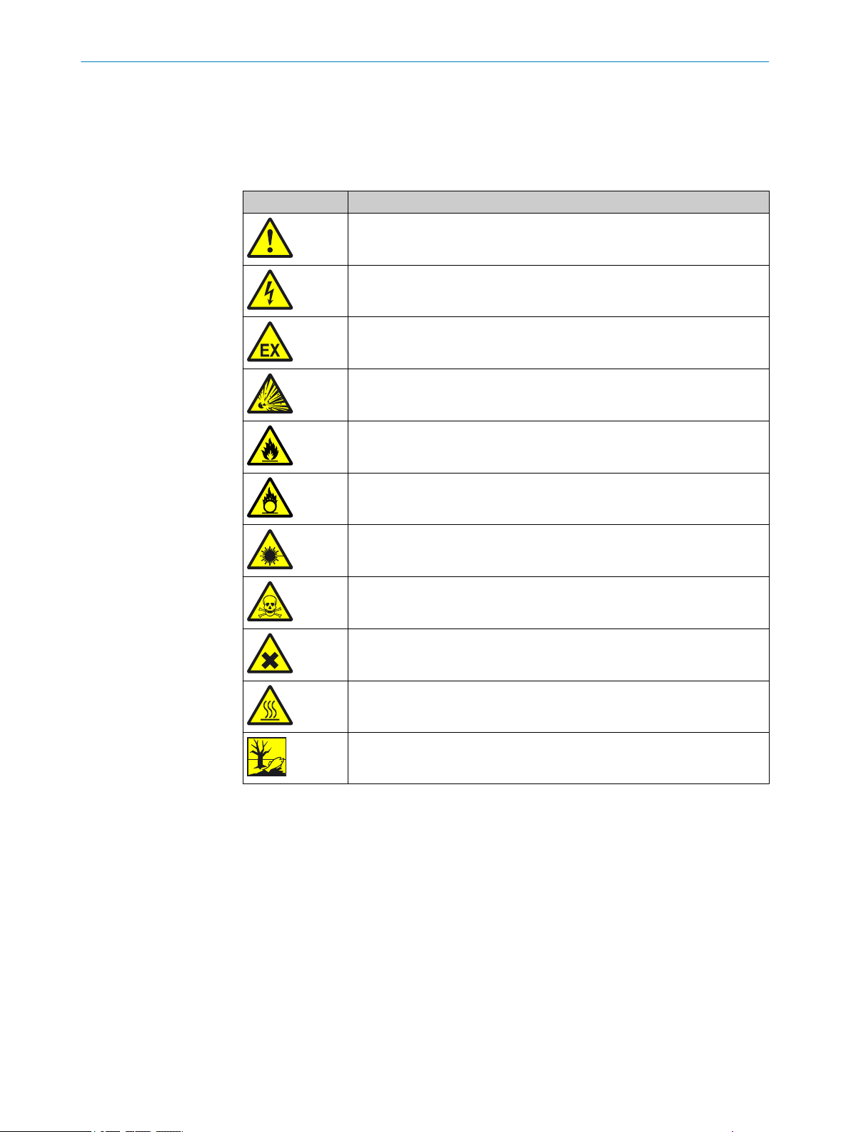
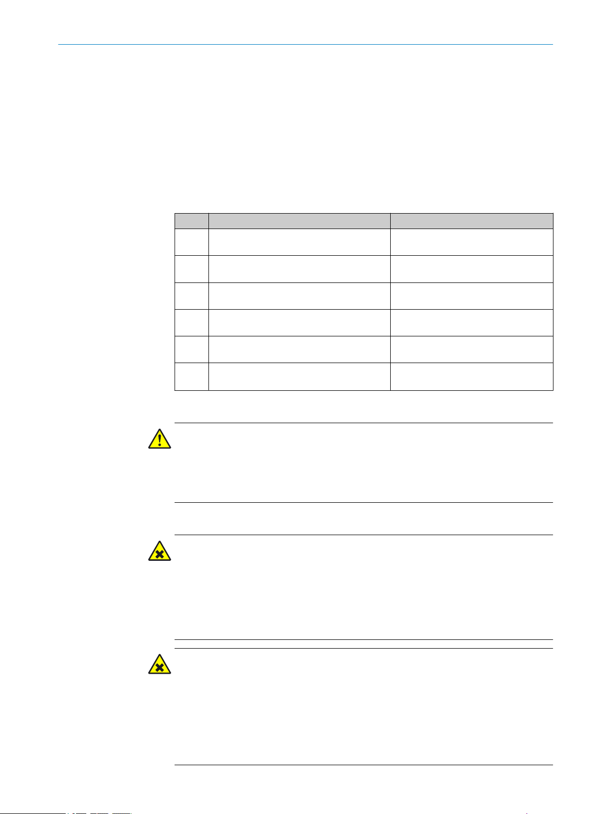
1.6.1 Warning symbols
Table 1: Warning symbols
Symbol Meaning
Hazard (general)
Hazard by voltage
Hazard in potentially explosive atmospheres
Hazard by explosive substances
Hazard by inflammable substances
1.6.2 Warning levels / Signal words
DANGER
Risk or hazardous situation which will result in severe personal injury or death.
WARNING
Hazard by oxidizing substances
Hazard by laser radiation
Hazard by toxic substances
Hazard by noxious substances
Hazard by high temperature
Hazard for the environment/nature/organic life
Risk or hazardous situation which could result in severe personal injury or death.
CAUTION
Hazard or unsafe practice which could result in less severe or minor injuries.
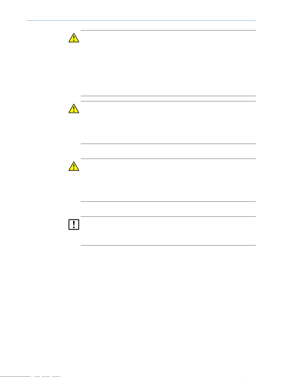
Notice
Hazard which could result in property damage.
Note
Hints
8
O PE R AT I NG IN S TR U CT I ON S | GM700 Ex 8019532/100Q/V1-1/2018-08 | SICK
Subject to change without notice
Page 9
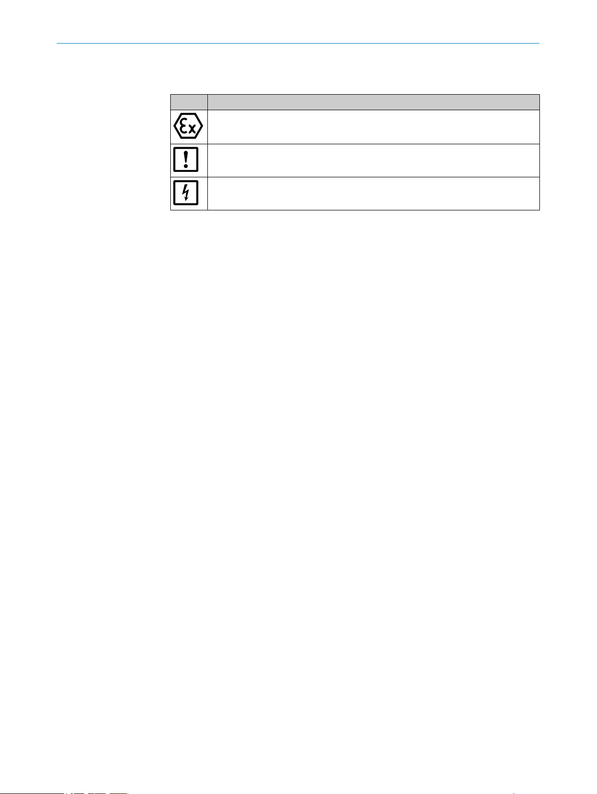
1.6.3 Information symbols
Table 2: Information symbols
Symbol Significance
ABOUT THIS DOCUMENT 1
Information on consistency of the product relative to Guideline 2014/34/EU (ATEX)
Important technical information for this product
Important information on electric or electronic functions
8019532/100Q/V1-1/2018-08 | SICK O P ER A TI N G I NS T RU C TI O NS | GM700 Ex
Subject to change without notice
9
Page 10
2 SAFETY INFORMATION
2 Safety information
2.1 Main operating information
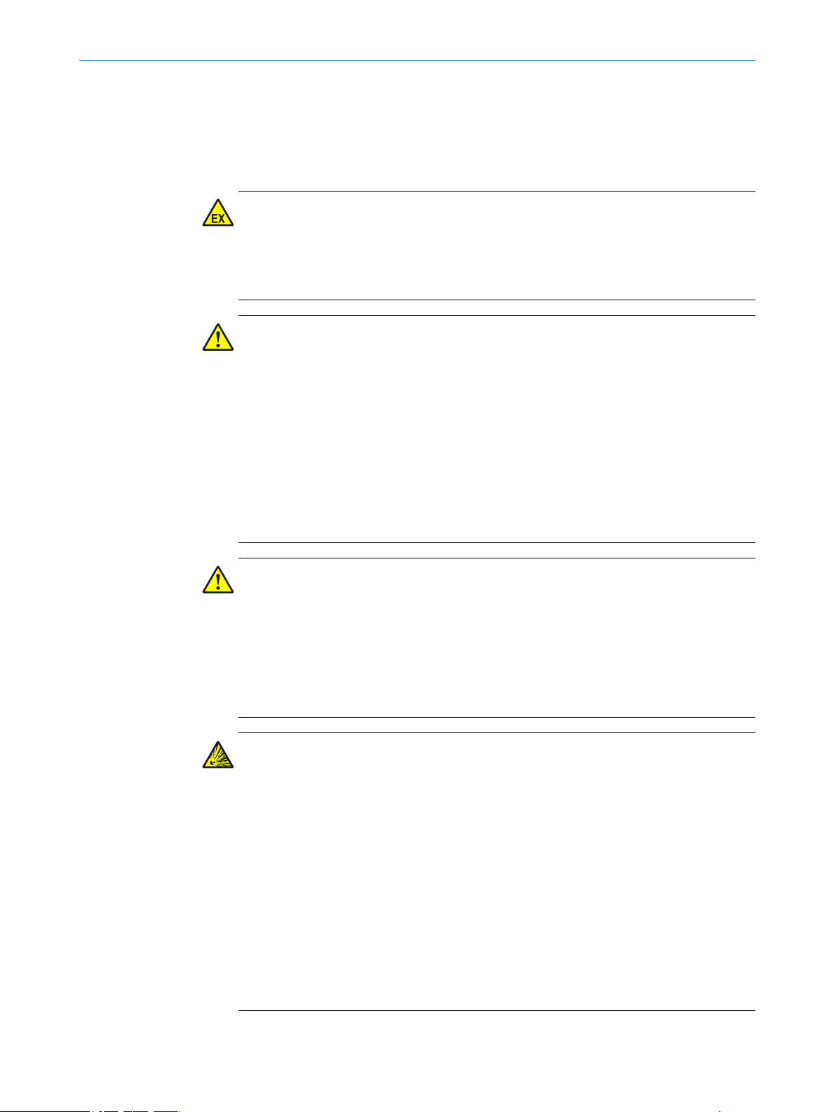
Work on the device
WARNING
Risk of explosion
Work on the device assumes an Ex free zone at the installation location otherwise there
is an explosion risk.
Ensure the work area is Ex free when working on the device.
b
WARNING
Injury risk through incorrect lifting and carrying of the device
Injuries can occur due to the weight and projecting enclosure parts when the equip‐
ment tips over or drops.
Consider the device weight before lifting.
b
Observe the regulations for protective clothing (e.g., safety shoes, non-slip gloves).
b
Grip underneath the equipment when possible to carry it safely.
b
Do not use projecting parts on the device to carry the device.
b
Call in further personnel for assistance as required.
b
Use a hoist or transport equipment as an option.
b
Pay attention to the transport safety device.
b
Clear obstacles that could cause falls and collisions out of the way.
b
DANGER
Risk for system safety through work on the device not described in these Operating
Instructions
Carrying out work on the device not described in these Operating Instructions or associ‐
ated documents can lead to unsafe operation of the measuring system and therefore
endanger plant safety.
Only carry out the work on the device described in these Operating Instructions
b
and associated documents.
DANGER
Risk of explosion through incorrect performance of maintenance work
Incorrect performance of maintenance work in potentially explosive atmospheres can
cause serious injuries to people and damage during operation.
Maintenance and commissioning tasks as well as checks should only be carried
•
out by experienced/trained personnel with knowledge of the rules and regulations
for potentially explosive atmospheres, especially:
– Ignition protection types
– Installation procedures
– Zone classification
Standards to be applied:
•
– IEC 60079‑14, Annex F: Knowledge, expertise and competence of responsi‐
ble persons, craftsmen and designers
– IEC 60079-17: Electrical installations inspection and maintenance
– IEC 60079-19: Equipment repair, overhaul and reclamation
10
O PE R AT I NG IN S TR U CT I ON S | GM700 Ex 8019532/100Q/V1-1/2018-08 | SICK
Subject to change without notice
Page 11

SAFETY INFORMATION 2
Laser radiation
WARNING
Eye injuries through laser radiation
The invisible laser beam within the SR-unit is not accessible when fitted. Observe the
following when the SR-unit of the device is swiveled open during installation work for
test purposes and the laser beam is activated:
Never look directly into the laser aperture when opening the SR-unit.
b
Laser protection class 1: Wear laser protection glasses despite low radiation.
b
Observe national valid limit values and standards that refer to these for industrial
b
safety.
Escaping hot gas
DANGER
Risk of fire through hot gas escaping in installations with overpressure conditions
On installations with overpressure, the purge air hose can be severely damaged by
escaping hot gas and can catch fire depending on the temperature. On installations
with overpressure as well as gas temperatures over 200°C:
Regularly check the functionality of the reverse flow safeguard fitted in the mea‐
b
suring probe.
DANGER
Danger to life by leaking hot/toxic gases
Hot and/or noxious gases can escape during work on the gas duct, depending on the
plant conditions.
Work on the gas duct may only be performed by skilled technicians who, based on
b
their technical training and knowledge as well as knowledge of the relevant regula‐
tions, can assess the tasks given and recognize the hazards involved.
Electrical safety
WARNING
Endangerment of electrical safety during installation and maintenance work when the
power supply is not switched off
An electrical accident can occur during installation and maintenance work when the
power supply to the device and/or lines is not switched off using a power isolating
switch/circuit breaker.
Before starting the work, ensure the power supply can be switched off using a
b
power isolating switch/circuit breaker in accordance with DIN EN 61010.
Make sure the power isolating switch is easily accessible.
b
An additional separation device is mandatory when the power isolating switch can‐
b
not be accessed or only with difficulty after installation of the device connection.
The power supply may only be switched on again after work completion or for test
b
purposes by the persons carrying out the work under consideration of the valid
safety regulations.
8019532/100Q/V1-1/2018-08 | SICK O P ER A TI N G I NS T RU C TI O NS | GM700 Ex
Subject to change without notice
11
Page 12
2 SAFETY INFORMATION
DANGER
Endangerment of electrical safety through missing power isolating switch
An electrical accident can occur during installation and maintenance work when the
power supply to the device and/or lines cannot be switched off using a power isolating
switch/circuit breaker.
b
b
WARNING
Endangerment of electrical safety through power cables with incorrect rating
Electrical accidents can occur when the specifications for replacement of a removable
power cable have not been adequately observed.
b
Contamination of device through purge air failure
Ensure the power supply can be switched off using a power isolating switch/circuit
breaker in accordance with DIN EN 61010-1:2010.
An additional disconnecting device is mandatory when the disconnector switch is
difficult to access or cannot be accessed when connecting the equipment after
installation.
Always observe the exact specifications in the Operating Instructions (Technical
Data Chapter) when replacing a removable power line.
CAUTION
A faulty purge air supply can damage the measuring system
The measuring system can no longer be protected from contaminated sample gas and
is damaged.
When the purge air supply appears faulty, immediately perform all actions
b
described in these Operating Instructions.
Responsibility for the safety of a system
ATTENTION
Responsibility for the safety of a system
The person setting the system up is responsible for the safety of the system in which
the device is integrated.
12
O PE R AT I NG IN S TR U CT I ON S | GM700 Ex 8019532/100Q/V1-1/2018-08 | SICK
Subject to change without notice
Page 13
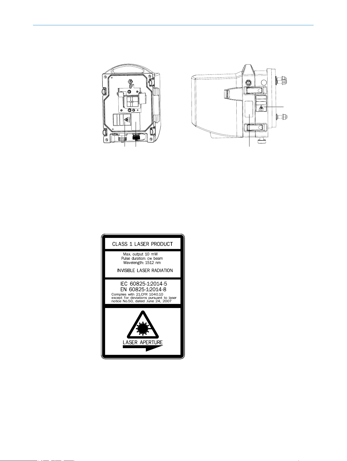
2.2 Warning information on the device
112 2
S/R unit
Figure 1: Warning information on the sender/receiver unit
SR-unit, front side
1 Danger sign: Laser radiation
2 Type plate GM700 Ex
SR-unit, right side
1 Danger sign: Laser radiation
2 Type plate GM700 Ex
SAFETY INFORMATION 2
Figure 2: Laser symbol on device
8019532/100Q/V1-1/2018-08 | SICK O P ER A TI N G I NS T RU C TI O NS | GM700 Ex
Subject to change without notice
13
Page 14

2
1
3
4
2 SAFETY INFORMATION
GM 700 Ex evaluation unit
Figure 3: Warning information on the EvU GMA700 front and right sides
1
2
3
4
Protective gas warning
•
Protective gas outlet
•
Risk of suffocation when using inert gases
•
20 minutes waiting time before opening the enclosure
General warning: Warning of danger area
Warning sign: Pull power plug before opening the device
Type plate
2.3 Intended use
2.3.1 Purpose of the device
The device serves exclusively for emission and process monitoring of gases in industrial
plants.
The device measures continuously directly in the gas duct (in-situ).
2.4 Responsibility of user
NOTICE
Responsibility for the safety of a system
The plant operator may not make any technical changes to the GM700 system. Every
change voids the EU type approval.
Intended users
see "Target groups (and document structure)", page 7.
Correct project planning
Basis of this Manual is the delivery of the device according to the preceding
•
project planning (e.g., based on the SICK application questionnaire) and the rele‐
vant delivery state of the device (see delivered System Documentation).
w
If you are not sure whether the device corresponds to the state defined dur‐
ing project planning or to the delivered system documentation: Please con‐
tact SICK Customer Service.
14
O PE R AT I NG IN S TR U CT I ON S | GM700 Ex 8019532/100Q/V1-1/2018-08 | SICK
Subject to change without notice
Page 15

SAFETY INFORMATION 2
Special local conditions
In addition to the information in these Operating Instructions, follow all local laws, tech‐
nical rules and company-internal operating directives applicable wherever the device is
installed.
Read the Operating Instructions
Read and observe these Operating Instructions.
b
Observe all safety instructions.
b
If anything is not clear: Please contact SICK Customer Service.
b
Document retention
These Operating Instructions:
Must be kept for reference.
b
Must be passed on to new owners.
b
8019532/100Q/V1-1/2018-08 | SICK O P ER A TI N G I NS T RU C TI O NS | GM700 Ex
Subject to change without notice
15
Page 16
01
02
03
04 05
06
07
01
02
03
04 05
06
07
3 PRODUCT DESCRIPTION
3 Product description
3.1 Product identification
Product name GM700 Ex
Device version Measuring Probe Version
Manufacturer SICK AG
Type plates
3.2 Product characteristics
■
The device serves for continuous measurement of gas concentrations in industrial
plants
■
The device is an in-situ measuring system which means measuring is done directly
in the gas carrying duct
■
Measuring components: NH3, NH3 + H2O
■
Measuring principle: Diode laser spectroscopy (TDLS)
Erwin-Sick-Str. 1 · D-79183 Waldkirch · Germany
Sender/receiver unit: On right side
•
Control unit: On right side
•
On measuring probe: On purge air fixture
•
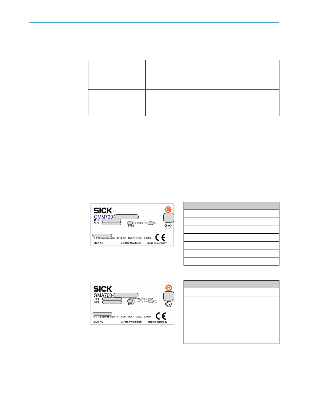
3.3 Type plate
Sender/receiver unit
No. Variable
01 Type code
02 Material number
03 Serial number
04 Min. gas temperature
05 Max. gas temperature
06 QR code
07 Month/year
Evaluation unit and connection unit
No. Variable
01 Type code
02 Material number
03 Serial number
04 Min. gas temperature
05 Max. gas temperature
06 QR code
07 Month/year
16
O PE R AT I NG IN S TR U CT I ON S | GM700 Ex 8019532/100Q/V1-1/2018-08 | SICK
Subject to change without notice
Page 17
3.4 Device variants
1
8
9
5
3
2
ß
4
6
7
Sender/receiver unit
Table 3: Type code identification
Variants Measured components
Ex zone 2: GMM700-0513EX3G
•
Ex zone 2: GMM700-0913EX3G
•
Connection unit
Table 4: Type code identification
Version
Ex zone 2: GMA700-035X EX3G
•
3.5 Pressure and temperature sensor
A p/T sensor serves to measure pressure and temperature, see "Installation example",
page 28 and page 36.
NH
3
NH3 / H2O
PRODUCT DESCRIPTION 3
3.6 Options
Cover plate for purge air fixture of the sender/receiver unit
•
Weatherproof cover
•
Purge air unit
•
3.7 Layout and function
Figure 4: GM700 Ex layout and function
Sender/receiver unit GM700-0xxEX3G
1
Evaluation unit GM700-035xEX3G
2
Ex-p control FS840
3
Metallic connecting hose between sender/receiver unit and evaluation unit
4
Digital purge medium valve, 230 V, G3/8", 2 mm, Ex-p
5
8019532/100Q/V1-1/2018-08 | SICK O P ER A TI N G I NS T RU C TI O NS | GM700 Ex
Subject to change without notice
17
Page 18

3 PRODUCT DESCRIPTION
Purge air fixture (without electronics)
6
GMP measuring probe (without electronics)
7
Temperature and pressure measurement
8
Purge air supply
9
Pressure switch for purge air monitoring
ß
Function
The device serves for continuous measurement of gas concentrations in industrial plants
•
The device is an in-situ measuring system which means measuring is done directly in the gas carrying duct
•
Measuring components: NH3, NH3 + H2O as well as reference values temperature and pressure
•
Measuring principle: Diode laser spectroscopy (TDLS) (laser protection class 1)
•
To maintain measuring reliability, a permanent air flow (optics purge air) protects and keeps the optics free
•
from soot and dust particles as well as condensate and moisture condensation
Ignition protection type “pressurized enclosure” is effective when using the GM700 Ex in Zone 2 potentially
•
explosive atmospheres. All relevant enclosures of the sender/receiver unit and connection unit connected
together via a pressure-proof metal hose are purged with a protective gas. The protective gas can be air suc‐
tioned in from the non-potentially explosive atmosphere or an inert gas.
3.7.1 Function of the pressurized enclosure
Purpose of the pressurized enclosure
The pressurized enclosure ensures Ex atmosphere cannot enter the device from out‐
side. To this purpose, the gas analyzer enclosure is filled with a protective gas. Apart
from that, it is ensured that the gas pressure inside the gas analyzer enclosure is higher
than the surrounding air pressure.
Functionality during operation
The pressurized enclosure system functions in “leakage compensation” mode: An over‐
pressure is generated in the device in relation to the atmosphere after pre-purging has
completed. If the protective gas pressure sinks below the minimum pressure set, pro‐
tective gas feed is activated until the selected overpressure is reached again.
Safety functions
If the maximum permitted overpressure is exceeded or the maximum permitted under‐
pressure underrun, the Ex control unit switches an alarm contact which must be perma‐
nently evaluated (responsibility of plant operator, see FS840 Pressurized Enclosure
Manual).
3.8 Purge air unit
•
•
•
The purge air unit must be in an Ex-free area and suction Ex-free purge air
The purge air unit supplies filtered ambient air to the measuring probe
This protects the front window of the SR-unit and the reflector in the measuring
probe against contamination and high gas temperatures
18
The purge air is blown into the gas duct through the “flange with tube”.
•
NOTE
Further information on the purge air unit, see Operating Instructions of the purge air
unit.
O PE R AT I NG IN S TR U CT I ON S | GM700 Ex 8019532/100Q/V1-1/2018-08 | SICK
Subject to change without notice
Page 19

3.9 Check cycle
PRODUCT DESCRIPTION 3
Cyclic check cycle for zero and sensitivity checks
Start a check cycle via
Timer trigger: Configurable 0 ... 1440 minutes (= 1 day), see menu “Settings /
•
Check Cycle”
External digital input signal (Di 1)
•
Purpose of check cycle
■
Checking the zero point and span point without feeding span gases.
Check cycle procedure
The measuring sequence to determine the zero and check point is performed. The digi‐
tal input uses a falling edge for triggering, i.e. performance of a check cycle is sup‐
pressed as long as the signal is high (e.g., for control purposes).
Signaling
“Function control” (relay 3) is signaled per digital output during output of the zero and
check point.
Output
The output runs for 90 seconds each for the zero point followed by the check point.
Unit and scaling for the current zero point according to the settings.
•
Check or span point is displayed as percentage scaled to 70% of the measuring
•
range.
The same calculation method is used for the deviation as for the gas concentration with
the exception of correction factors which result from a gas adjustment as well as cus‐
tomer correction factors from menu PAR/SETTINGS / REGRESS. FUNCT. During the
check cycle output, the zero and span point are displayed in the lower display line paral‐
lel to the analog output. These can be viewed in menu DIAG/CHECK VALUES/<GAS> for
subsequent checks. Prerequisite is that the output has already been made via an ana‐
log output.
Deviations
A warning message is output, e.g., “AO1 NH3 ZEROPoint” when the zero or check point
deviation is above 2% of the upper display limit of an analog output.
The warning message remains until the next check cycle output is within the tolerance.
8019532/100Q/V1-1/2018-08 | SICK O P ER A TI N G I NS T RU C TI O NS | GM700 Ex
Subject to change without notice
19
Page 20

PRODUCT DESCRIPTION
3
3.10 Explosion protection in accordance with ATEX
3.10.1 Operation in potentially explosive atmosphere
3G / Zone 2: Connection unit and sender/receiver unit
The GM700 Ex complies with ATEX Directive 2014/34/EU with the
following characteristics:
X II 3/-G Ex pzc op is [ia] IIC T4 Gc/-
•
Special conditions (X identification):
•
A measuring function for explosion protection is not part of the
°
EC type approval
Explosion protection relating to optical radiation in the measuring
•
channel
The explosion protection relating to optical radiation in the measur‐
ing channel is satisfied in accordance with the temperature range
(-20°... +60 °C) specified by ATX/IECEx. The plant operator must
evaluate Ex atmospheres possibly present for exhaust gas temper‐
atures exceeding this range separately and take suitable protective
measures!
w
Location of Ex relevant subassemblies, see Chapter “Design
and Function”.
w
Do not remove, add or modify any components to or on the
device unless described and specified in the official manufac‐
turer information. Otherwise the approval for the device for
use in potentially explosive atmospheres becomes void.
w
Adhere to the maintenance intervals, see Chapter “Mainte‐
nance plan”.
w
After switching off the main power supply: Wait 20 minutes
before opening the enclosure.
20
O PE R AT I NG IN S TR U CT I ON S | GM700 Ex 8019532/100Q/V1-1/2018-08 | SICK
Subject to change without notice
Page 21
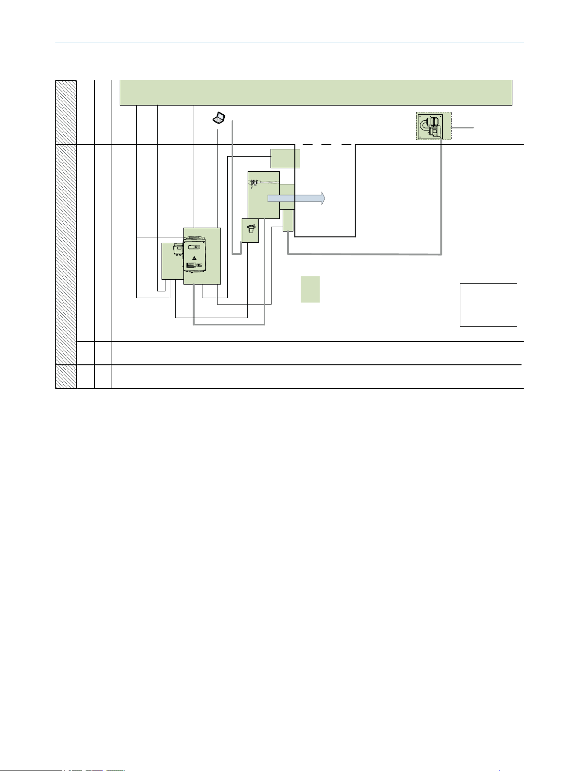
3.10.2 Zone of use GM700 Ex 3G components
DI/DO/
AI/AO
230 /
115 V
ß
à
GM700
Ex ATEX 3G
á
Ex p
[op is]
p/t
Ex ia
Ex m
6
Ex p/ Ex i
Ex na
nc
8
5
1
3
4
â
Non Ex
ã ä
æ
9
å
DIV 1
DIV 2
Non Ex
1G
2G
Non Ex3GNon ExZone 2Zone 1
Zone 0
2
7
PRODUCT DESCRIPTION 3
Figure 5: Zone of use GM700 Ex 3G components
Components
Control station / measuring station
1
Sender/receiver unit
2
Measuring beam
3
Ex-p valve
4
Evaluation unit
5
Overpressure control
6
8
7
9
ß
à
á
â
ã
ä
å
æ
p/T sensor
p sensor for purge air unit
Pressure controller for optics purge air as selected by the plant operator
Lines
Purge air hose, optics
Connecting hose, Ex-p
Pressure controller for optics purge air as selected by the plant operator
Ex-p error case signal
Service interface
Ex-p protective gas feed, from plant operator
Feed, optics purge air
Measuring channel
Measuring channel, Ex-free
8019532/100Q/V1-1/2018-08 | SICK O P ER A TI N G I NS T RU C TI O NS | GM700 Ex
Subject to change without notice
21
Page 22
3 PRODUCT DESCRIPTION
3.10.3 Pressurized enclosure system
Ignition protection type, pressurized enclosure for Zone 2
Purging
All relevant enclosures of the sender/receiver unit and connection unit connected
together via a pressure-proof metal hose are purged with a protective gas. Purging
before starting the device safely removes any possible ignitable mix.
Controlling the overpressure in the enclosure
Control by the purge medium valve SVD.L.2.-AI00 G3/8"-300L Ex-p of the FS840
ensures that the complete enclosure is always kept at an overpressure of at least 0.8
mbar against the atmosphere after pre-purging; this prevents an ignitable gas mix pen‐
etrating the device.
Protective gas types
Instrument air suctioned in from the area outside the potentially explosive atmos‐
•
phere
Inert gas
•
NOTE
The temperature of the protective gas must not be higher than 50°C.
More information, see "Technical data for Protective gas", page 92, and Pressurized
Enclosure Operating Instructions.
3.10.3.1 Safety functions
Alarm signal of pressurized enclosure in case of malfunction
Ex control unit FS840 for Category 3G:
The Ex control unit FS840 provides a falling edge when the pressurized enclosure
is not in the correct operating state (malfunction).
WARNING
Risk of explosion through incorrect parameter settings
Incorrect parameter setting can cause an explosion with fatal consequences.
Only authorized persons are allowed to change the parameters.
b
NOTICE
The operating company is responsible for the evaluation of the alarm signal. See the
Pressurized Enclosure System Manual.
3.11 Sender/receiver unit - evaluation unit connecting hose
The following is applicable for the connecting hose between sender/receiver unit and
evaluation unit:
22
It is part of the pressurized enclosure
•
It contains electrical connection lines
•
It is under overpressure
•
It must be connected to the potential equalization system
•
To ensure potential equalization, the mechanical screw fittings of the hose attach‐
•
ment on GMM700 and GMA700 are secured additionally with sprocket discs.
These sprocket discs may not be removed.
O PE R AT I NG IN S TR U CT I ON S | GM700 Ex 8019532/100Q/V1-1/2018-08 | SICK
Subject to change without notice
Page 23
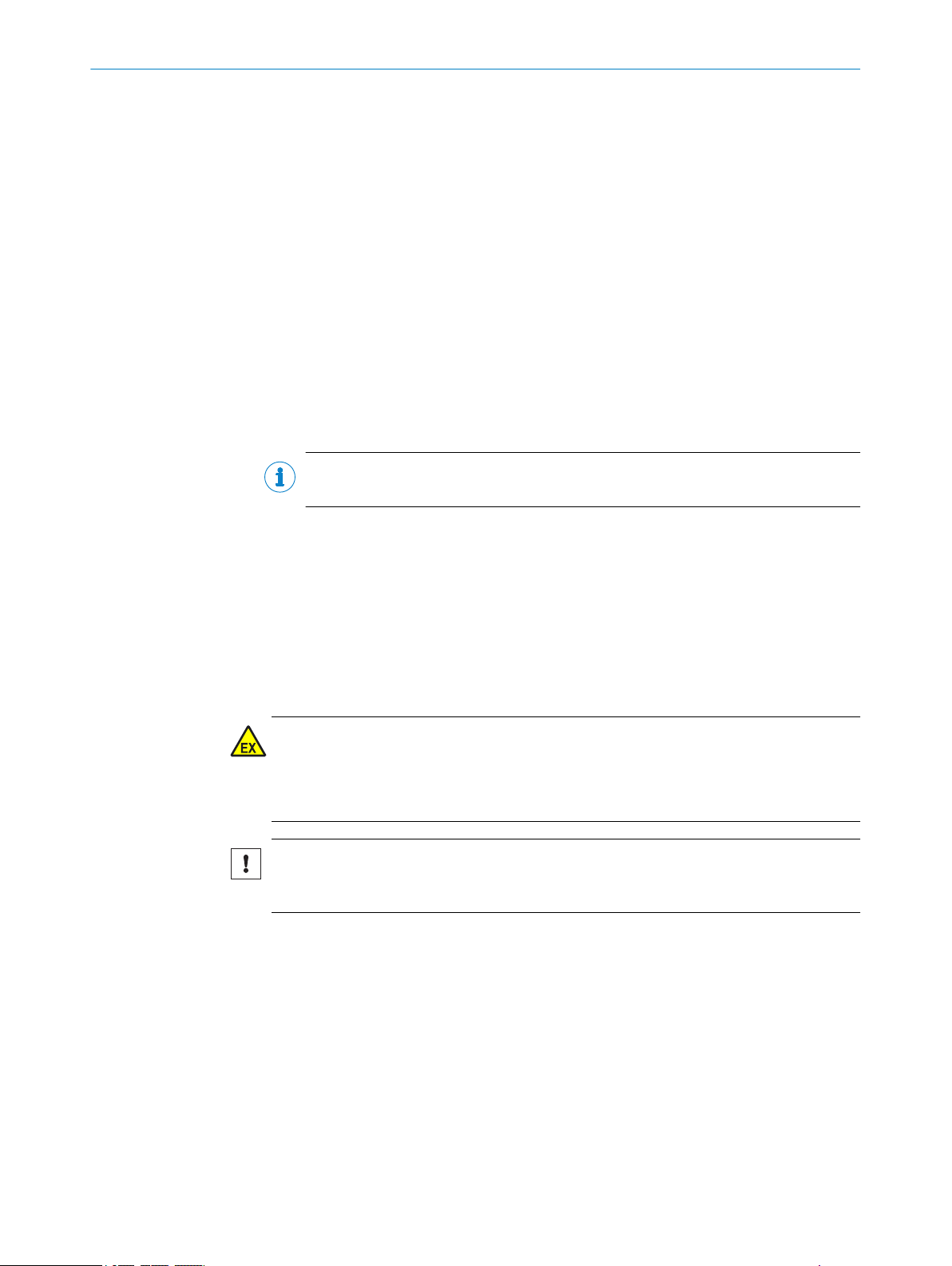
3.12 GMP measuring probe in detail
3
2
open Close
4
6
1
5
PRODUCT DESCRIPTION 3
Figure 6: GMP measuring probe description
Reflector
1
Measuring gap: Exposed measuring path
2
Purge air outlet: Air outlet in the duct 90° to gas flow direction (directed purge air)
3
Lever (locking device of the opening to sample gas)
4
Differential pressure sensor for purge air
5
Lever and locking device in “open” position
6
NOTE
Further characteristics of the GMP measuring probe, see "Measuring probe", page 91
and page 95.
8019532/100Q/V1-1/2018-08 | SICK O P ER A TI N G I NS T RU C TI O NS | GM700 Ex
Subject to change without notice
23
Page 24
3
1
2
4 TRANSPORT AND STORAGE
4 Transport and storage
4.1 Transport protection
Removing the transport safety device on the SR-unit
1 Open the lock and swivel the flange fixture open.
2 Check the transport safety device for damage.
3 Remove the transport safety devices (see Figure).
4 Store the transport safety device.
24
Figure 7: Transport safety device on the SR-unit
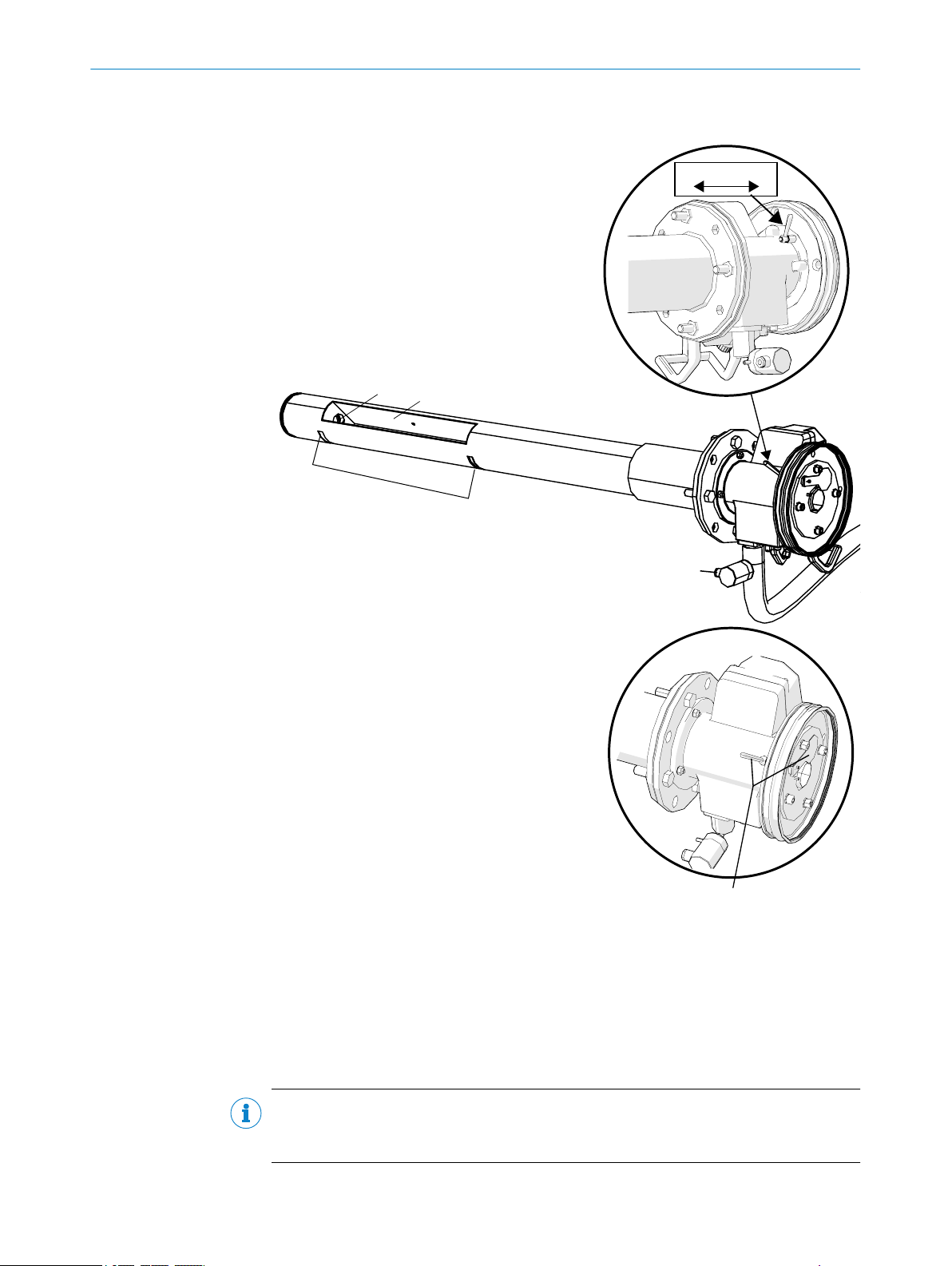
Remove the front cover of the sender/receiver unit
1
Figure 8: Transport safety device on the GMP measuring probe
2 plastic protective caps to cover the optics
1
Remove the protective stickers
2
Set the locking device to the "close" position
3
O PE R AT I NG IN S TR U CT I ON S | GM700 Ex 8019532/100Q/V1-1/2018-08 | SICK
Subject to change without notice
Page 25

4.2 Storage
TRANSPORT AND STORAGE 4
DANGER
Risk to health through contaminated measuring probe
Depending on the composition of the gas in the measuring channel, the measuring
probe could be contaminated with substances which could result in serious health
damage.
Decontaminate the measuring probe before storage.
b
Wear the specified protective clothing for all work with a contaminated measuring
b
probe.
Clean all components of the measuring system with slightly damp cleaning cloths.
b
Use a mild cleaning agent here.
Protect the openings of the sender/receiver-unit and measuring probe from atmos‐
b
pheric influences, preferably with the original transport safety devices.
Pack all components for storage or transport. Preferably use the original packing.
b
Store all components of the measuring system in a dry, clean room.
b
8019532/100Q/V1-1/2018-08 | SICK O P ER A TI N G I NS T RU C TI O NS | GM700 Ex
Subject to change without notice
25
Page 26
5 MOUNTING
5 Mounting
5.1 Information on installation in potentially explosive atmospheres
Project planning for measuring channel
NOTICE
Observe information in Chapter “Main operating information”.
NOTICE
Hazard when exceeding the temperature classes for hot gas ducts
Temperature class T4 (max. 135 °C), for which the explosion protection of this device is
designed, can be exceeded on hot gas ducts.
Plan appropriate thermal insulation of the duct and the flanges during project
b
planning/assembly.
When necessary, ensure adequate ventilation or cooling.
b
Correct installation
DANGER
Risk for system safety through work on the device not described in these Operating
Instructions
Carrying out work on the device not described in these Operating Instructions or associ‐
ated documents can lead to unsafe operation of the measuring system and therefore
endanger plant safety.
Only carry out the work on the device described in these Operating Instructions
b
and associated documents.
DANGER
Risk of explosion through incorrect installation
Incorrect assessment of the installation location as well as all further installation work
in potentially explosive atmospheres can cause serious injuries to people and damage
during operation.
Installation, commissioning, maintenance and inspection may only be carried out
•
by skilled persons having knowledge of the relevant rules and regulations for
potentially explosive atmospheres, especially:
– Ignition protection types
– Installation regulations
– Zone classification
Standards to be applied:
•
– IEC 60079-14, Annex F: Knowledge, skills and competencies of responsible
persons, operatives and designers
– IEC 60079-17: Electrical installations inspection and maintenance
– IEC 60079-19: Equipment repair, overhaul and reclamation
26
Local work safety regulations must be observed
•
O PE R AT I NG IN S TR U CT I ON S | GM700 Ex 8019532/100Q/V1-1/2018-08 | SICK
Subject to change without notice
Page 27

WARNING
Risk of injury when the device drops down
The weight of the device can cause it to drop down and cause injuries during the work
described in this chapter.
b
Ex-suitable measuring probe
DANGER
Risk of explosion with a measuring probe not suitable for Ex zones
Measuring probes not approved for operation in potentially explosive atmospheres can
cause an explosion.
b
5.2 Tools required
Tools Part No. Required for
Adjustment device 2034121 Alignment of "flanges with tube"
19 mm jaw wrench Flange screw fitting
Screwdriver Connections
Allen key Connections
MOUNTING 5
Carry out assembly work on parts of the device together with another person when
necessary.
Only use the GMP measuring probe included in the scope of delivery from SICK.
5.3 Material required
Material Required for
Personal protective equipment Protection when working at the sampling point
Tubes for protective gas Protective gas feed line, see "Connecting the protective gas
5.4 Preparing the sampling point
The operating company is responsible for preparing the sampling point
NOTICE
Basis for determining the sampling point:
Preceding project planning (e.g., based on the SICK application questionnaire)
•
Regulations of the local authorities
•
Responsibility of the operator
Determine sampling point
•
Preparing the sampling point
•
Feed and drain for protective gas
•
on the SR-unit", page 52.
8019532/100Q/V1-1/2018-08 | SICK O P ER A TI N G I NS T RU C TI O NS | GM700 Ex
Subject to change without notice
27
Page 28

1
2
4
6
3
5
7
8
à
ä
9
ß
á
â
ã
ø133
5 MOUNTING
DANGER
Risk of explosion through suctioning optics purge air from an Ex zone
Zone separation is no longer ensured when the purge air supply to purge the optics is
suctioned in from an Ex zone. This can lead to an explosion.
Always make sure the air for the purge air supply is suctioned in from an Ex-free
b
zone and ensure sufficient tightness of the purge air path when it passes through
an Ex atmosphere.
NOTICE
Observe zone separation, see "Zone of use GM700 Ex 3G components", page 21.
5.5 GM700 Ex scope of delivery
Check the scope of delivery according to the order confirmation/delivery note.
5.6 Installation sequence
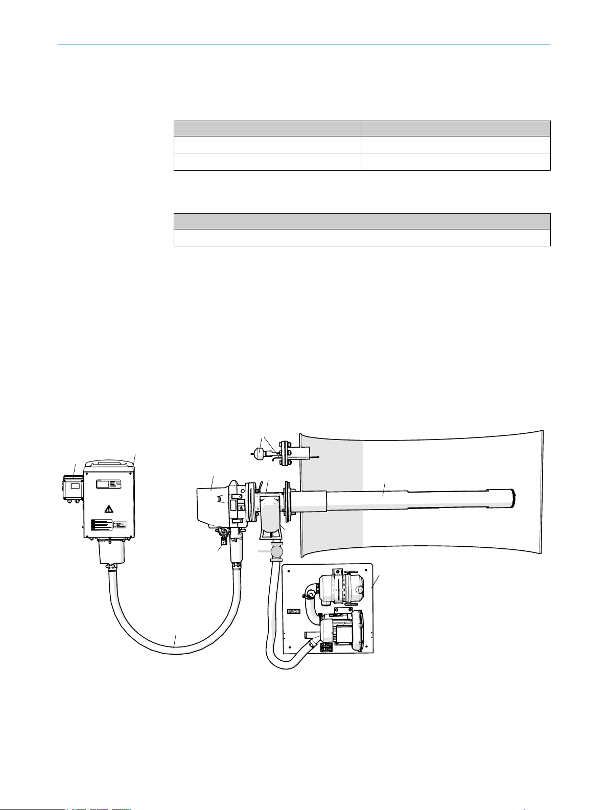
5.6.1 Installation example
Carry out assembly according to the project planning and the Inspection protocol. The dimensions specified in the
drawings are guidelines and can deviate strongly from the project planning.
Figure 9: Assembly example, all dimensions in mm
Components
Evaluation unit with Ex-p control FS840
1
GM700 Ex sender/receiver unit
2
GMP measuring probe
3
Purge air unit
4
Pressure and temperature sensor (installation location according to project planning)
5
Ex-p control FS840
6
Dimensions
Max. distance SR-unit -EvU: 4 m, 8 m, depending on hose length
7
Duct wall - SR-unit: depending on flange with tube length + measuring probe length
8
28
O PE R AT I NG IN S TR U CT I ON S | GM700 Ex 8019532/100Q/V1-1/2018-08 | SICK
Subject to change without notice
Page 29
Minimum clearance (center) - working platform: 1300 - 1500 mm
9
Min. flange length in gas duct: 20 mm
ß
Flange with tube length: Standard 240 mm
à
Minimum clearance flange (center) to purge air supply: > 700 mm
á
Vertical clearance fastening drill holes - purge air supply assembly plate: 470 mm
â
Horizontal clearance fastening drill holes - purge air supply assembly plate: 470 mm
ã
Miscellaneous
Working platform
ä
5.6.2 Overview of installation steps (duct-side preparation)
Step Procedure Reference
1 Fit flange with tube. see "Installing the flange with tube",
2 Install evaluation unit. see "Install the evaluation unit",
3 Fit purge air unit or units. see "Installing the purge air unit",
4 Observe protective gas outlet (evaluation
unit).
5 Connect pressure, temperature and purge air
monitor.
6 Connect protective gas feed to sender/
receiver unit.
MOUNTING 5
page 29
page 31.
page 33.
see "Install the FS840", page 31.
see "Connecting pressure, temperature
and purge air monitor ", page 41.
see "Connecting the protective gas on
the SR-unit", page 52.
Information on installing the measuring probe in the gas duct
CAUTION
Device damage through fitting the measuring probe too early on the gas duct
Unsuitable ambient conditions or the atmosphere in the measuring channel can dam‐
age the measuring system and make commissioning impossible.
Carry out the commissioning steps as described in the Commissioning Chapter.
b
5.6.3 Installing the flange with tube
DANGER
Hazard through hot, explosive or toxic flue gases
Hot and/or noxious gases can escape during assembly work on the gas duct depending
on plant conditions.
Work on the gas duct may only be performed by skilled persons who, based on
b
their technical training and knowledge as well as knowledge of the relevant regula‐
tions, can assess the tasks given and recognize the hazards involved.
DANGER
Hazard through hot, toxic and corrosive flue gases
Hot and/or noxious gases can escape during assembly work on the gas duct depending
on plant conditions.
Switch the plant off when working on the gas duct
b
or
the plant operator determines the safety measures to be observed during work on
b
the plant when switched on based on an evaluation of the danger involved.
8019532/100Q/V1-1/2018-08 | SICK O P ER A TI N G I NS T RU C TI O NS | GM700 Ex
Subject to change without notice
29
Page 30
1
200
18
4
5
°
5 MOUNTING
CAUTION
Device damage through incorrect/missing insulation of the duct when the measuring
channel is hot
When the measuring channel is hot, plan the duct and flange insulation so that
b
the device is protected against high temperatures.
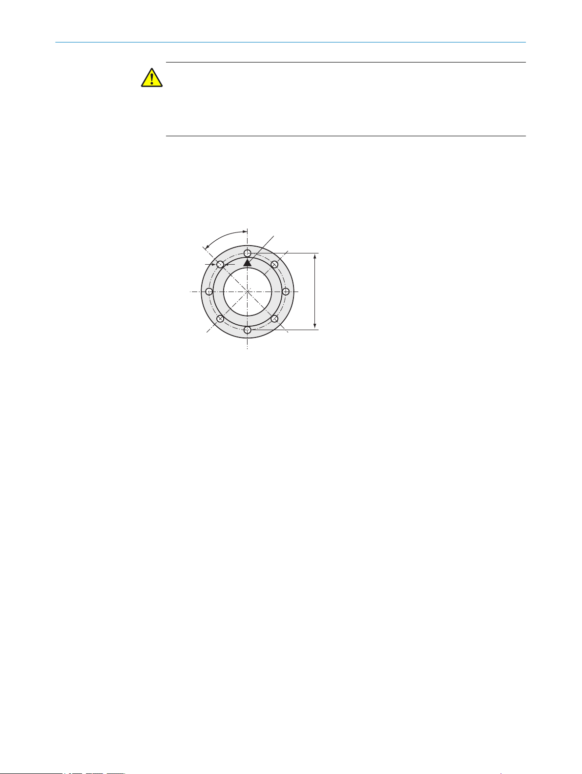
Installing the flange with tube on the gas duct
1 Cut openings on the gas duct for the flange with tube.
2 Insert the flange with tube. Pay attention to the following:
The "Top" marking must point upwards vertically, irrespective of the gas duct
°
angle.
The tube must project at least 30 mm into the gas duct
°
Figure 10: "Top" marking on flange with tube
Marking “Top”
1
3 Attach the flange with tube.
4 Tilt the tube slightly downwards (max. 1°) to allow any condensate to drain off.
5 Now fix the flange with tube properly to the gas duct. Make sure that the alignment
of the flange does not change.
6 If necessary, attach duct insulation to protect the device from heat.
30
O PE R AT I NG IN S TR U CT I ON S | GM700 Ex 8019532/100Q/V1-1/2018-08 | SICK
Subject to change without notice
Page 31

5.6.4 Install the evaluation unit
1
1
MOUNTING 5
Figure 11: Assembly brackets GMA700 Ex 3G
1
b
b
see figure 40, page 97
NOTICE
Do not yet connect the evaluation unit electrically.
5.6.4.1 Install the FS840
Assembly information
When setting up outdoors, it is recommended to protect the explosion-proof device
against direct atmospheric influences, e.g., with a protective roof.
Ensure the protective gas inlet and outlet are in a horizontal axis.
Brackets
•
Drill holes: Ø 8 mm
•
Screws: M6
Fasten the connection unit with 4 M6 screws as shown in the dimension drawing.
Refer to the dimension drawings for the dimensions.
8019532/100Q/V1-1/2018-08 | SICK O P ER A TI N G I NS T RU C TI O NS | GM700 Ex
Subject to change without notice
31
Page 32

1
2
5 MOUNTING
Figure 12: Protective gas outlet
Protective gas outlet: Thread G1"
1
Reference opening (M5 inner thread)
2
Protective gas quality
Instrument air or inert gas
•
Compressed air, class 533 according to ISO 8573-1
•
Solid matter 40 µm (class 1)
•
Pressure dew point ≤ 20 °C (class 3)
•
Oil quality ≤ 0.01 mg/m3 (class 1)
•
The air quality may possibly have to be better depending on the requirements of the
devices fitted in the pressurized enclosure.
Protective gas outlet
It is important that protective gas can flow out of the protective gas outlet against the
atmospheric pressure.
Ensure the unhindered flow of the protective gas.
b
Reference opening
The reference opening must be located in the Ex area.
Make sure the opening is always clear.
b
Line lengths for protective gas supply
Large pressure losses occur during the purge phase (high purge medium throughput)
depending on the supply line diameter. Consider this when dimensioning the supply
line:
Reference values: With 4 mm line diameter (inner diameter), a pressure loss of 500
mbar per meter must be calculated during purging with 2 l/s.
32
The pressure losses are noticeable when the purge medium flow rate is too low so that
the device is possibly not completely pre-purged.
O PE R AT I NG IN S TR U CT I ON S | GM700 Ex 8019532/100Q/V1-1/2018-08 | SICK
Subject to change without notice
Page 33

NOTE
More information on protective gas,
see "Technical data for Protective gas", page 92.
•
5.6.5 Installing the purge air unit
NOTE
Purge air hose to the device according to project planning.
NOTE
For information on installing the purge air unit, see the Operating Instructions of the
purge air unit.
MOUNTING 5
8019532/100Q/V1-1/2018-08 | SICK O P ER A TI N G I NS T RU C TI O NS | GM700 Ex
Subject to change without notice
33
Page 34

6 ELECTRICAL INSTALLATION
6 Electrical installation
6.1 Electrical installation safety information
NOTICE
Observe information in Chapter “Main operating information”.
Electrical safety
WARNING
Endangerment of electrical safety during installation and maintenance work when the
power supply is not switched off
Before starting the work on the device, ensure the power supply can be switched
b
off using a power disconnector switch/circuit breaker in accordance with DIN EN
61010-1.
Make sure the power disconnector switch is easily accessible.
b
An additional disconnecting device is mandatory when the power disconnector
b
switch cannot be accessed or only with difficulty after installation of the device
connection.
After completion of the work or for test purposes, the power supply may only be
b
activated again by authorized personnel complying with the safety regulations.
WARNING
Endangerment of electrical safety through power cable with incorrect rating
Electrical accidents can occur when the specifications for replacement of a power line
have not been adequately observed.
Always observe the exact specifications in the Operating Instructions (Technical
b
Data Chapter) when replacing a power line.
DANGER
Danger of electrical accidents
Incorrect performance of electrical work could result in serious electrical accidents.
Only let the work described in the following be carried out by electricians familiar
b
with potential hazards.
CAUTION
Risk of device damage
Electronic components are accessible when the enclosure is open. The circuit board
can be severely damaged when a contact is not grounded when the power supply is
switched on.
First switch the power supply on when the sender/receiver unit and the control
b
unit are closed.
34
CAUTION
Device damage through short circuit on the device
The internal electronics can be damaged when signal connections are established and
the power supply is switched on. This is also valid for plug connections.
Disconnect the GM32 Ex and any connected devices from the voltage supply.
b
O PE R AT I NG IN S TR U CT I ON S | GM700 Ex 8019532/100Q/V1-1/2018-08 | SICK
Subject to change without notice
Page 35

ELECTRICAL INSTALLATION 6
Ex information
DANGER
Risk of explosion through incorrect performance of maintenance work
Incorrect performance of maintenance work in potentially explosive atmospheres can
cause serious injuries to people and damage during operation.
Maintenance and commissioning tasks as well as checks should only be carried
•
out by experienced/trained personnel with knowledge of the rules and regulations
for potentially explosive atmospheres, especially:
– Ignition protection types
– Installation procedures
– Zone classification
Standards to be applied:
•
– IEC 60079‑14, Annex F: Knowledge, expertise and competence of responsi‐
ble persons, craftsmen and designers
– IEC 60079-17: Electrical installations inspection and maintenance
– IEC 60079-19: Equipment repair, overhaul and reclamation
DANGER
The Ex certification becomes void when line inlets and plugs without approval are
used
The line inlets and plugs are part of the Ex protection and therefore require approval.
Do not replace line inlets or plugs with other types.
b
Line inlet dimensions, see "Dimension drawings, evaluation unit with pressurized
b
enclosure system FS840", page 97.
DANGER
Risk of explosion through non-Ex conform installation of the lines to the device
Incorrect installation of the supply lines (power supply, signal and communication lines)
through Ex zones can lead to an electrostatic charge. This creates an increased risk of
explosion.
Install all lines in accordance with EN61010-1 and EN60079-14.
b
Protect lines against electrostatic charges.
b
WARNING
Risk of explosion through incorrect or non-existing grounding
To avoid an explosion due to electrostatic discharge, a correctly connected potential
equalization is mandatory on all system components with external ground connections
in all operating conditions.
Connect a potential equalization on all planned points on the device components.
b
Ensure the potential equalization is connected during all work on the device
b
described in these Operating Instructions.
8019532/100Q/V1-1/2018-08 | SICK O P ER A TI N G I NS T RU C TI O NS | GM700 Ex
Subject to change without notice
35
Page 36

1
4
3
1
2
5
6
7
8
9
6 ELECTRICAL INSTALLATION
DANGER
Risk of explosion through incorrect connection of the external sensors
The explosion protection is endangered when the external sensors p/T (in the stack) as
well as the optics purge air monitor (on the purge air fixture) are not connected to the
intrinsically safe terminals provided in the connection unit.
Always connect the external sensors p/T (in the stack) as well as the optics purge
b
air monitor (on the purge air fixture) to the intrinsically safe terminals specified in
the connection unit for this purpose.
Observe the intrinsically safe connection values for the Ex barriers fitted in the
b
evaluation unit in the Operating Instructions delivered.
DANGER
Risk of explosion through unsuitable screw fittings and lines
Only use lines (according to EN60079-14) with suitable outer diameters.
b
Close off cable inlets “vapor-proof” (virtually gas-tight).
b
Protect lines against electrostatic charges.
b
Only open those cable inlets to be used for installing cables. Keep the plugs. Refit
b
the original plug when a cable inlet must be closed again afterwards.
Electromagnetic compatibility
NOTE
This is a Class A product. This device can cause radio interference in household envi‐
ronments and therefore the user must take suitable measures when necessary.
6.2 Connection overview
Observe zone separation, see "Zone of use GM700 Ex 3G components", page 21.
Figure 13: GM700 Ex 3G / zone 2 connection diagram
Power supply
1
Warning signal, Ex-p control FS840
2
36
O PE R AT I NG IN S TR U CT I ON S | GM700 Ex 8019532/100Q/V1-1/2018-08 | SICK
Subject to change without notice
Page 37

Service interface
3 12
1
1
3
I/O signal lines
4
Protective gas supply
5
Connection line, pressure sensor
6
Connection line, temperature sensor
7
Connection line, purge air monitor, pressure switch
8
Connection line, purge medium valve SVD.L.2.-AI00 G 3/8“-300L Ex p
9
Metallic connecting hose between sender/receiver unit and evaluation unit
ß
6.2.1 Lines
ELECTRICAL INSTALLATION 6
Figure 14: Evaluation unit, version 3G
No. Line opening size Line diameter (clamping
range)
M16 x 1.5 5 - 11 mm 6 Nm 5
1
M20 x 1.5 10 - 14 mm 10 Nm 1
2
M16 x 1.5 5 - 10 mm 6 Nm 4
3
Table 5: Lines
Lines Remark
Power supply From customer: 3 x 1.5 mm
Evaluation unit power supply From customer: 3 x 1.5 mm
Evaluation unit - sender/receiver unit with con‐
necting hose
Differential pressure sensor (measuring probe)
- evaluation unit
Pressure/temperature input From customer, intrinsically safe I/O connec‐
Service interface From customer, RS232
Inputs/outputs From customer: Terminal connections: 6 x
Evaluation unit - temperature sensor From customer
Evaluation unit - pressure sensor From customer
In accordance with project planning
5 m
•
10 m
•
From customer, intrinsically safe I/O connec‐
tion
tion
0,75 mm
Tightening torque Qty.
2
2
2
8019532/100Q/V1-1/2018-08 | SICK O P ER A TI N G I NS T RU C TI O NS | GM700 Ex
Subject to change without notice
Table 6: Technical data, M screw fittings
Outer thread M20 x 1.5 M16 x 1.5
Thread length 6 mm
Height 23 mm
37
Page 38

1
5
3
2
4
6 ELECTRICAL INSTALLATION
Outer thread M20 x 1.5 M16 x 1.5
Cable diameter 10 ... 14 mm 6 ... 10 mm
Key width 24 mm 20 mm
Continuous service temperature -20 ... 95 °C
Material Nickel-plated brass
6.3 Connecting interfaces
6.3.1 Connect I/O interfaces
CAUTION
Never lay power supply cables directly next to signal cables.
DANGER
Risk of explosion through non-Ex conform installation of the lines to the device
Incorrect installation of the supply lines (power supply, signal and communication lines)
through Ex zones can lead to an electrostatic charge. This creates an increased risk of
explosion.
Install all lines in accordance with EN61010-1 and EN60079-14.
b
Protect lines against electrostatic charges.
b
1 Route the data lines through the M screw fittings.
2 Connect the data line.
NOTE
The analog input assignment shown in the following Chapter is the default setting and
may not be modified.
6.3.1.1 GM700 Ex 3G terminal connection diagram
Figure 15: Connection diagram of connection unit for variant 3G / Ex zone 2
Power supply
1
Connections of temperature sensor (3-wire circuit): Pins 1,2 and 3
2
Connections of pressure sensor: Pins 4 and 5
3
Pressure monitor for purge air monitoring: Pins 6 and 9
4
38
O PE R AT I NG IN S TR U CT I ON S | GM700 Ex 8019532/100Q/V1-1/2018-08 | SICK
Subject to change without notice
Page 39

ELECTRICAL INSTALLATION 6
Connection area for intrinsically safe components
5
NOTICE PAY CLOSE ATTENTION TO THE CONNECTION VALUES ON TERMINALS 1-9
In area5, the intrinsically safe connections for temperature 2, pressure 3 and a digital input 4 to connect the
pressure monitor are provided. Only connect intrinsically safe simple operating means with suitable connection
data to these terminals in accordance with the Table below. Otherwise the explosion protection of the connected
sensors is not ensured. Only connect intrinsically safe devices with appropriate connection data to these termi‐
nals.
Table 7: Connection data for intrinsically safe connections
Termi‐
Inlet sizes Gas
nal
1 Inlet, temperature sensor
PT100, 3-wire circuit RMA42
2 IIB ≤ 360 nF ≤ 2 mH k.A.
group
IIC ≤ 27.3 V ≤ 22.1mA151mWk.A. 8 nF 75 μH ≤ 85 nF ≤ 500 μH k.A.
Uo Io Po Ui Ci1Li Co
3
3 IIB ≤ 530 nF ≤ 5 mH k.A.
4 Analog input, pressure sen‐
sor 4-20 mA RMA42
5 IIB ≤ 683 nF ≤ 17 mH k.A.
IIC ≤ 27.3 V ≤ 96.5mA659mWk.A. 8 nF 75 μH ≤ 88 nF ≤ 4 mH k.A.
IIA ≤ 2 280 nF ≤ 34 mH k.A.
6 Digital input, pressure switch
1 KCD2-SR-Ex
7 IIB ≤ 16.8 µF ≤ 486.3 mH 1628
IIC 10.5V 17.1mA45mW12 V 0 0 2.41 µF ≤ 121.5 mH 801
IIA ≤ 75 µF ≤ 972.7 mH 1628
8 Digital input, pressure switch
2 KCD2-SR-Ex
9 IIB ≤ 16.8 µF ≤ 486.3 mH 1628
IIC 10.5V 17.1mA45mW12 V 0 0 ≤ 2.41 µF ≤ 121.5 mH 801
IIA ≤ 75 µF ≤ 972.7 mH 1628
1
Max. inner capacity
2
Max. inner inductivity
3
Max. outer capacity
4
Max. outer inductivity
5
L/R ratio (inductivity/resistance)
Lo
4
μH/ Ω
8019532/100Q/V1-1/2018-08 | SICK O P ER A TI N G I NS T RU C TI O NS | GM700 Ex
Subject to change without notice
39
Page 40

+ – + – + –
+ – + – + –
+ – + – + –
PE
N
L1
V
4
2+
230 V AC;
50 Hz
(3 x 1.5
2
)
1 2 3
Power
+5V +24V
Power CAN
+24V
+ – H L GND
Digital inAnalog i n
0.. 20mA
100 100 100
40...60Hz
AO1 AO2 AO3DI1 DI2 AI1 AI2 AI3
Sensor
DO1 DO2 DO3
Digital out
AC/DC 48V 30VA 1A
Analog out
0.. 20mA
Sensor
Fuse 2.5 AT 250V
PE N L1
contrast
1
PE N L1
T
T
CAN H
CAN L
--- +++
2
6 4 3
7 8
DI3
5
6 ELECTRICAL INSTALLATION
6.3.1.2 Electrical connection of the evaluation unit EvU
Figure 16: Electrical connection of the evaluation unit
GM700 Ex evaluation unit
1
Connections on circuit board
2
3
4
5
6
7
8
Power supply GM700
Fuse, 2.5 2,5 AT, 250 V
CAN GM700
Analog outputs: 0 ... 20 mA (6 x 0.75 mm2)
Digital outputs 48 V AC/DC; 60 VA, 1 A (6 x 0.75 mm2)
1 = digital output (NC contact) for malfunction
2 = digital output (NO contact) for maintenance request
3 = digital output (NO contact) for function check
40
O PE R AT I NG IN S TR U CT I ON S | GM700 Ex 8019532/100Q/V1-1/2018-08 | SICK
Subject to change without notice
Page 41

1
2
ELECTRICAL INSTALLATION 6
6.4 Connecting the connecting hose to the SR-unit on the EvU
NOTICE
The connecting hose between the SR-unit and the evaluation unit is part of the pressur‐
ized enclosure. It is under overpressure.
Protect the connecting hose against possible damage.
b
1 Lead the cable through the M screw fittings, see Figure below.
2 Connect the cable in the connection unit.
3 Tighten screws on the terminal strip.
4 Push on the connector housing and screw tight.
Figure 17: Connecting the connecting hose of the SR-unit on the EvU
M screw fitting
1
Connector housing
2
6.5 Connecting pressure, temperature and purge air monitor
NOTE
Purge air monitor - pressure controller for purge air monitoring
Wiring layout, see "Connection overview", page 36.
•
Terminal assignment, see "GM700 Ex 3G terminal connection diagram", page 38.
•
Observe the Operating Instructions of the sensors and the purge air monitor.
•
6.6 Preparing the power supply
1 Check that the connection lines meet the requirements:
– Cross-section: 3 x 1.5 mm
2 Plan a disconnecting device for
– Evaluation unit (see "Evaluation unit Ex version I/O module", page 91).
– Optics purge air units (see technical data of the optics purge air unit).
– Mark the disconnecting device as disconnecting device for the GM700 Ex.
8019532/100Q/V1-1/2018-08 | SICK O P ER A TI N G I NS T RU C TI O NS | GM700 Ex
Subject to change without notice
2
41
Page 42

6 ELECTRICAL INSTALLATION
3 Connect power cable and lines:
w
w
4 Tighten the M screw fitting.
Figure 18: Power connection in the evaluation unit, power supply 230V / 50 Hz
NOTICE
The PE connection must always be connected to the protective ground of the system.
Route the power cable through the M screw fitting.
Connect the lines in the connection unit.
6.7 Connecting the FS840 Ex overpressure control
Electrical safety
The local electrical installation regulations must be observed.
Risk of explosion
DANGER
Risk of explosion through incorrect settings for the pressurized enclosure
The pressurized enclosure is a central safety part of the device. All work is described in
this Manual and the relevant specified documents. If work is performed which is not
described in this Manual, the risk of explosion of the measuring system increases and
the ATEX certification for the device becomes void.
Carry out all work skillfully and in accordance with the delivered documentation.
b
Unsafe measuring operation
CAUTION
Risk of unsafe measuring operation through loss of degree of protection IP65
Ineffective seals of the connection unit and insufficient closed openings for unused line
inlets can lead to loss of degree of protection IP65. Penetration by dust or moisture can
lead to unsafe operation of the FS840.
Close off unused openings for line inlets with impact resistant sealing plugs that
b
have been checked against self-loosening and turning.
Check the seals on the Ex-e enclosure for damage and replace as necessary.
b
Tighten the terminals, especially in the Ex-e area.
b
Check the terminals for discoloration. This could indicate increased temperatures.
b
Check the gland screw fittings, sealing plugs and flanges for leak tightness and
b
tight seat.
42
O PE R AT I NG IN S TR U CT I ON S | GM700 Ex 8019532/100Q/V1-1/2018-08 | SICK
Subject to change without notice
Page 43

Terminal assignment
ELECTRICAL INSTALLATION 6
Figure 19: Connecting the Ex overpressure control
Terminals
1
Table 8: Terminal assignment
Terminals Designation
1, 2 Signal contact 1
3, 4 Signal contact 1
5, 6 Connection for purge medium valve
7, 8 – power supply (feed)
9, 10 + power supply (feed)
Table 9: Terminals with higher safety in the FS840
Tightening torques Wire cross-sections rigid / flexible
Min. 0.3 Nm Min. 0.3 mm
Max. 0.4 Nm Max. 2.5 mm
2
2
NOTICE
Always maintain the limit values on the respective terminals. Refer to the Technical
Data or the Test Certificate for the limit values. The fitted valve fuse must correspond to
the specified fuse value of the purge medium valve used.
Limit values, see "Limit values for terminal assignment FS840", page 92.
NOTE
Further information on the pressurized enclosure system, see "Pressurized enclosure
system settings", page 92 and FS840 Operating Instructions.
8019532/100Q/V1-1/2018-08 | SICK O P ER A TI N G I NS T RU C TI O NS | GM700 Ex
Subject to change without notice
43
Page 44

1
2
6 ELECTRICAL INSTALLATION
6.8 Electrical connection of SR-unit
NOTICE
The connecting hose between the SR-unit and the evaluation unit is part of the pressur‐
ized enclosure. It is under overpressure.
Protect the connecting hose against possible damage.
b
Figure 20: Connection of connecting hose with
the SR-unit
Connect the connecting hose to the SR-unit:
1 Connect the connecting hose plug on the SR-unit.
2 Push on the cover and screw tight.
6.9 Connecting the potential equalization
NOTICE
A potential equalization not connected properly or missing can lead to malfunctions in
device operation.
44
O PE R AT I NG IN S TR U CT I ON S | GM700 Ex 8019532/100Q/V1-1/2018-08 | SICK
Subject to change without notice
Page 45

6.9.1 Connecting the potential equalization on the SR-unit
1
1
Figure 21: Connecting the potential equalization on the SR-unit
Screw the grounding conductor (4 mm2) of the plant ground tight to the screw ter‐
b
minal.
ELECTRICAL INSTALLATION 6
6.9.2 Connecting the potential equalization on the measuring probe
Figure 22: Potential equalization on the GMP measuring probe
Potential equalization connection
1
Screw the grounding conductor tight on the screw terminal.
b
8019532/100Q/V1-1/2018-08 | SICK O P ER A TI N G I NS T RU C TI O NS | GM700 Ex
Subject to change without notice
45
Page 46

1
2
6 ELECTRICAL INSTALLATION
6.9.3 Potential equalization - evaluation unit and Ex control unit
Connect the grounding conductor on the EvU
1 Lead the potential equalization (4 mm2) of the plant ground with one eyelet over
the bolt.
2 Position and tighten the M6 nut.
Connect the grounding conductor on the Ex control unit FS840
Screw the potential equalization (4 mm2) of the plant ground tight to the screw ter‐
b
minal.
Figure 23: Potential equalization on Ex control unit and evaluation unit
Potential equalization connection on Ex control unit
1
Potential equalization connection on evaluation unit
2
46
O PE R AT I NG IN S TR U CT I ON S | GM700 Ex 8019532/100Q/V1-1/2018-08 | SICK
Subject to change without notice
Page 47

7 Commissioning
7.1 Safety information on commissioning
NOTICE
Observe information in Chapter “Main operating information”.
Technical knowledge needed / requirements for commissioning
NOTICE
You have fundamental knowledge of the GM700
•
You are familiar with national and local requirements regarding setting up and
•
operating devices in potentially explosive atmospheres.
You are familiar with conditions at the installation location, especially possible haz‐
•
ards through the gases in the gas duct (hot/dangerous to health). You are capable
of recognizing and preventing danger by possibly escaping gases.
If one of these requirements is not met:
Please contact SICK Customer Service or your local representative.
b
COMMISSIONING 7
Laser radiation
WARNING
Eye injuries through laser radiation
The invisible laser beam within the SR-unit is not accessible when fitted. Observe the
following when the SR-unit of the device is swiveled open during installation work for
test purposes and the laser beam is activated:
Never look directly into the laser aperture when opening the SR-unit.
b
Laser protection class 1: Wear laser protection glasses despite low radiation.
b
Observe national valid limit values and standards that refer to these for industrial
b
safety.
Grounding
CAUTION
Device damage through incorrect or non-existing grounding
During installation and maintenance work, it must be ensured that the protective
grounding to the devices and/or lines involved is effective in accordance with EN
61010-1.
System safety
ATTENTION
Responsibility for the safety of a system
The person setting the system up is responsible for the safety of the system in which
the device is integrated.
7.2 Prerequisites for successful commissioning
Required Operating Instructions:
Operating Instructions, measuring system GM700 Ex
•
8019532/100Q/V1-1/2018-08 | SICK O P ER A TI N G I NS T RU C TI O NS | GM700 Ex
Subject to change without notice
47
Page 48

7 COMMISSIONING
Operating Instructions, purge air supply
•
Gönnheimer Pressurized Enclosure FS840 and Purge Medium Valve Manual
•
Final inspection protocol
•
Table 10: Prerequisites for successful commissioning
All specifications are met in accordance with the project planning. Inspection based on the
Final inspection protocol carried out.
Electrical installation - completed and checked.
The measuring system is installed and electrically connected.
SR-unit, measuring probe and purge air fixture are first fitted and connected electrically
during commissioning.
Function test (blower rotation direction) of the purge air unit has been carried out.
Sampling point has been checked for free access without hazards.
The optical interfaces of the device have been cleaned.
Technical data of the measuring point (customer's notes)
Table 11: Technical data of the measuring point
Measuring range
Limit values
Inputs and outputs to be used
7.3 Material required
Not contained in the scope of delivery
Optical alignment tool
•
19 mm open-end wrench
•
Insulated screwdriver set
•
Allen key set
•
Optical cleaning cloth without cleaner
•
Personal protective equipment
•
– Hot surfaces on device
– In accordance with local regulations
7.4 Overview of commissioning steps
Table 12: Commissioning steps
Step Procedure Reference
1 Remove the transport safety devices. see "Transport protection", page 24
2 Fit the SR-unit on the measuring probe.
3 Carry out zero adjust. see "Zero adjust", page 49
4 Put the purge air supply into operation.
5 Align the measuring probe in flow direc‐
tion.
6 Connect the protective gas. see "Connecting the protective gas on the
see "Fitting the SR-unit on the measuring
probe.", page 49
see "Installing the purge air unit", page 33
see "Aligning the measuring probe in flow
direction", page 51
SR-unit", page 52
48
O PE R AT I NG IN S TR U CT I ON S | GM700 Ex 8019532/100Q/V1-1/2018-08 | SICK
Subject to change without notice
Page 49

7.5 Zero adjust
COMMISSIONING 7
Step Procedure Reference
7 Connect the potential equalization. see "Connecting the potential equalization
on the SR-unit", page 45
8 Electrical connection of SR-unit. see "Electrical connection of SR-unit",
page 44
9 Switch the measuring system on.
10 Optional: Fit the weatherproof cover. see "Installing the weatherproof cover ",
Prerequisite
1. Clean ambient atmosphere, free from sample gas, protected against weather.
2. Bracket for the measuring probe
NOTICE
Position the measuring probe bracket within reach of the metal hose between EvU
and SR-unit.
see "Optical fine alignment of the sender/
receiver unit ", page 54
see "Starting measuring operation",
page 56
page 55
7.6
Preparation
1 Switch the power supply of the evaluation unit on.
2 Wait for the 2.5 - 5 hours warming up time of the SR-unit (depending on ambient
conditions) to elapse.
NOTE
Signal output on the EvU when the warming up time is not reached yet:
1 LED: "Warning" is yellow.
2 Display: Message "DEV Temp" is output.
Carry out zero adjust
1 Align the optical beam path after the warming up phase, see "Optical fine align‐
ment of the sender/receiver unit ", page 54.
2 Select in menu cal:
– Zero Adjust – manual zero adjust (measuring path free from sample gas)
– Activate Calibration mode (button “cal”), carry out menu item Zero Adjust.
3 Confirm the prompt.
Zero Measuring is displayed whilst zero point adjustment executes.
Fitting the SR-unit on the measuring probe.
The flange fixture can be removed before installing the SR-unit.
8019532/100Q/V1-1/2018-08 | SICK O P ER A TI N G I NS T RU C TI O NS | GM700 Ex
Subject to change without notice
49
Page 50

1 2 3 4
5 6
1
2
3
4
5
6
7 COMMISSIONING
Figure 24: Fastening the GMP measuring probe on the SR-unit
SR-unit flange fixture (detachable)
1
Cup springs (10 per fastening)
2
Sealing ring
3
Centering disc and self-locking nut
4
Threaded pin of flange fixture
5
Device flange
6
Cross-section of the connection fitted between the SR-unit and measuring probe
Figure 25: Cross-section of the connection fitted between the SR-unit and measuring probe
1
2
3
4
5
6
Gap = 3 ±0.5 mm
Hose clamps
Sealing ring
10 cup springs
Spherical washer
Self-locking nut
50
O PE R AT I NG IN S TR U CT I ON S | GM700 Ex 8019532/100Q/V1-1/2018-08 | SICK
Subject to change without notice
Page 51

1
2
3
COMMISSIONING 7
1 Put 10 cup springs each, back-to-back, onto the three threaded bolts on the flange
fixture of the SR-unit.
2 Pull the sealing ring over the flange of the purge air fixture and hang it loosely over
the purge air unit.
3 Carefully push the measuring probe with the device flange onto the three threaded
bolts of the flange fixture fitted with cup springs.
4 Position the centering discs.
NOTICE
Observe the direction of the centering disc: The convex side must fit into the
groove on the purge air fixture.
5 Tighten the self-locking nuts with a wrench (19 mm) so that the cup springs are
slightly compressed and an even gap of approx. 3 ± 0.5 mm remains. This gap is
important for adjustment of the optical alignment.
6 Fit the sealing ring over the gap.
7 Push two hose clamps over the sealing ring and screw tight.
8 Refit the flange fixture back on the SR-unit when it was removed beforehand.
w
Insert the hinge pins back in and close the quick release fasteners.
9 Set the lever on the probe flange to the “open” position to open the locking device
on the probe towards the sample gas.
7.7 Aligning the measuring probe in flow direction
Flow direction aligned at the factory
NOTE
When the gas flow direction is already known during project planning, the installation
angle of the of the measuring probe is already set accordingly when delivered.
A sticker marks the setting.
Figure 26: Flow direction marking
Device flange
1
2
3
Flow direction sticker
Mounting ring screws (4 pcs.)
Measuring probe, aligning
The measuring probe can be adjusted by turning the device flange.
8019532/100Q/V1-1/2018-08 | SICK O P ER A TI N G I NS T RU C TI O NS | GM700 Ex
Subject to change without notice
51
Page 52

1
7 COMMISSIONING
1 Loosen the 4 screws on the mounting ring (see Figure).
2 Rotate the device flange to the following position:
– The measuring gap must point in flow direction.
– The device flange must be positioned so that the SR-unit can be fitted in a
vertical position.
3 Tighten the screws on the mounting ring again to fasten the device flange in this
position.
7.8 Feeding protective gas
NOTICE
The pressurized enclosure requires a permanent supply of protective gas to ensure the
Ex protection function.
Feed the protective gas via the protective gas connection.
b
Further information concerning protective gas:
– Requirements for protective gas, see "Technical data for Protective gas",
page 92.
– Protective gas outlet: see "Install the FS840", page 31.
7.8.1 Connecting the protective gas on the SR-unit
The protective gas connection is located underneath the enclosure of the sender/
receiver unit.
52
Figure 27: Connection for protective gas on GM700 Ex
Protective gas inlet:
1
•
Thread G3/8" or
•
hose connection for 8 mm diameter
O PE R AT I NG IN S TR U CT I ON S | GM700 Ex 8019532/100Q/V1-1/2018-08 | SICK
Subject to change without notice
Page 53

COMMISSIONING 7
NOTICE
Only use protective gas corresponding to the specifications, see "Technical data for Pro‐
tective gas", page 92.
8019532/100Q/V1-1/2018-08 | SICK O P ER A TI N G I NS T RU C TI O NS | GM700 Ex
Subject to change without notice
53
Page 54

1
2
3
4
5
7 COMMISSIONING
7.8.2 Switch the pressurized enclosure on
1 Switch the main power supply of the pressurized enclosure system on (at an exter‐
nal source).
2 The pressurized enclosure system starts pre-purging the enclosure with protective
gas. The Ex control unit signals the end of the pre-purge phase.
3 Switch the main power supply of the measuring system on (at an external source).
7.9 Optical fine alignment of the sender/receiver unit
CAUTION
Hazard by laser radiation
Device with a laser with protection class 1.
Do not hold any reflecting objects or objects that bundle the laser beam in the
b
laser beam.
During installation or maintenance: Disconnect the power supply before opening
b
the device.
Prerequisite
The power supply of the evaluation unit is switched on.
•
The device is in Maintenance mode.
•
Components of the alignment tool on the GM700
Figure 28: Components of the alignment tool on the SR-unit
Visor of the optical alignment tool
1
LED display for rough optical alignment
2
Alignment tool lever
3
Y-alignment: Vertical
4
X-alignment: Horizontal
5
Carry out optical fine alignment of the SR-unit
54
1 First turn the lever of the built-in alignment tool (3) and then pull it down to bring it
to the adjustment position, (see Figure above).
2 Look through visor (1) on the right enclosure side diagonally from above to the mir‐
ror with the target.
O PE R AT I NG IN S TR U CT I ON S | GM700 Ex 8019532/100Q/V1-1/2018-08 | SICK
Subject to change without notice
Page 55

1
2
COMMISSIONING 7
3 Align the position of the red light spot. To do this, adjust the nuts for the X and Y
alignment on the device flange so that the light spot in positioned in the center of
the target, see "Optical fine alignment of the sender/receiver unit ", page 54.
4 After successful alignment, push the lever of the alignment tool back to its original
position and secure it with a quarter turn.
Figure 29: Point for correct fine adjustment
Target for the alignment tool for the Cross-Duct version
1
Target for the alignment tool for the probe version
2
7.10 Installing the weatherproof cover
Installing the weatherproof cover of the sender/receiver unit:
1 Install the installation plate on the flange of the purge air fixture.
w
Lay the weatherproof cover upside down on the floor.
w
Open and unhinge the locking bolts on both sides.
w
Pull the installation plate upwards and remove it from the cover.
w
Remove the bottom mounting ring.
w
Place the installation plate onto the rubber band of the purge air fixture from
the top.
w
Position the mounting ring on the side of purge air fixture.
w
Screw the bottom mounting ring to the top mounting ring.
8019532/100Q/V1-1/2018-08 | SICK O P ER A TI N G I NS T RU C TI O NS | GM700 Ex
Subject to change without notice
55
Page 56

2
2
3
1
1
2
3
4
7 COMMISSIONING
1
1
2
3
Mounting ring
Locking bolts
Installation plate
2
Installation plate
1
Top mounting ring
2
Bottom mounting ring
3
2 Place the weatherproof cover on the installation plate.
w
Position the cover on the installation plate from the top.
w
Engage the locking bolts and close again.
7.11 Starting measuring operation
NOTE
The device is delivered from the factory with the parameter settings specified by the
customer when ordering. When these parameter specifications match the parameters
during commissioning, measuring operation can be started after fine optical alignment
by pressing the “meas” button. The device can be configured to meet the plant condi‐
tions when required.
Start Operating mode:
1 Switch Maintenance mode off, menu path: see "Menu tree Maintenance",
page 63.
2 Set Mode to“Off”.
3 Press “meas”.
56
O PE R AT I NG IN S TR U CT I ON S | GM700 Ex 8019532/100Q/V1-1/2018-08 | SICK
Subject to change without notice
Page 57

Checking status LEDs, error and warning messages
NOTE
Quick check of Measuring screens on the LC display of the evaluation unit:
b
When error or warning messages are present:
b
b
7.11.1 Operating states
Message on EvU display Meaning
INIT Initializing the evaluation unit
INITIALISATION
SIGNAL_ADJUST Adjusting amplification to changed transmission
MEASURING
MEASURING LL
MEASURING LD Measuring operation; beam length tracked (line locking
MAINTENANCE Maintenance mode (no measurement)
DOWNLOAD
COMMISSIONING 7
Using the Operating Instructions, see "Operating and display elements (evaluation
unit)", page 58.
Determine and clear the error cause using the Operating Instructions, see "Serial
interface commands - Diag", page 65, and the Error and Warning Message
Tables, see "Error messages", page 82 and see "Warning messages", page 84.
If the error cause cannot be cleared:
Contact SICK Service.
Initializing the SR-unit
Measuring operation
Measuring operation with active tracking of the laser
beam length (line locking)
done)
Download new software (for Service purposes only)
7.11.2 Select the ambient temperature range
NOTICE
Temperature stabilization: 30 minutes
The device stabilizes the temperature after the temperature is modified.
Warning message “DEV TEMP” is output during temperature stabilization.
•
1 Activate Parameter mode.
2 Menu path: Setting -> Ambient Temp.
3 Select the temperature range from the Table that matches the ambient conditions
best at the measuring location, see "Possible ambient temperatures", page 99.
8019532/100Q/V1-1/2018-08 | SICK O P ER A TI N G I NS T RU C TI O NS | GM700 Ex
Subject to change without notice
57
Page 58

8 OPERATION
8 Operation
8.1 Safety
WARNING
Hazard for persons and plant through unsafe operation of the measuring system
If the device is or could be in an unsafe state:
Put the device out of operation.
b
Disconnect the device from the main supply voltage and signal voltage.
b
Secure the device against unallowed or unintentional start-up.
b
NOTE
More information concerning the detection of unsafe operating states, see Chapter
“Visual check”.
8.1.1 Check before commissioning
Before every start-up
Check all enclosures are closed:
b
– Enclosure cover
– Cable inlets
– Enclosure openings
NOTICE
Permanent feed of protective gas must be ensured, see "Feeding protective
gas", page 52.
8.2 Operating and display elements (evaluation unit)
DANGER
Risk of explosion through releasing the Ex protection
The operating elements of the evaluation unit GMA700 can only be used when the eval‐
uation unit is opened. The zone separation is no longer ensured when the evaluation
unit is opened in the Ex zone during operation. This creates an explosion risk.
The Ex-p system generates a warning signal that the Ex protection is not effective.
To operate the measuring system via the operating elements:
Ensure an Ex-free atmosphere exists when opening the GMA700.
b
58
O PE R AT I NG IN S TR U CT I ON S | GM700 Ex 8019532/100Q/V1-1/2018-08 | SICK
Subject to change without notice
Page 59

NH3
mg/
m
3
236
Measuring
GM700
Evaluation Unit
1
3
4
Ref. conditions
Hum: wet
2
Figure 30: GM700 operator panel
Display
1
•
All current measured values
•
Computed values
•
Menu navigation
Status LEDs to signal operating and malfunction states
2
Function buttons for menu navigation and input
3
Function buttons for menu selection
4
OPERATION 8
LEDs
Table 13: Significance of LEDs
LED Significance / possible cause
OPERATION
SERVICE
Warning
MALFUNCTION
8.2.1 Function buttons
Measuring mode
•
The device is switched on, power voltage is available
•
Service mode
•
Warning message
•
At least one warning message pending
•
Reading warning messages, see Diagnosis mode (diag)
•
Device malfunction
•
At least one malfunction message pending
•
Reading malfunction messages, see Diagnosis mode (diag)
•
Button Function
MEAS Back to the Measuring screen from any menu. All inputs that have not been ter‐
minated with Save are discarded.
The current function of the function buttons is shown on the display.
Display Function
8019532/100Q/V1-1/2018-08 | SICK O P ER A TI N G I NS T RU C TI O NS | GM700 Ex
Subject to change without notice
Back Returns to next higher level menu.
59
Page 60

meas
8 OPERATION
Display Function
Diag To display warning and/or error messages (plain text) and retrieve sensor values:
Press this button.
Enter Call up/start/confirm selected menu function.
Select Select function/character.
Start Start procedure.
In a selection list: Move cursor upwards.
During input: Next character.
Move cursor downwards.
Move cursor to the left.
Move cursor to the right.
8.3 Menu tree of the evaluation unit
NOTE
Menu texts are shown in English.
8.3.1 Menu tree Measuring
Menu level Explanation
Measuring
Current measured values: Depending on
•
device version
Reference variables (wet, dry)
•
8.3.2 Menu tree Diagnosis
Menu level
Diagnosis Diagnosis
Malfunction Current error messages (plain text)
Warning Current warning messages (plain text)
Sensor values Displays diagnostic values and control values
GM700 Sensor values
GM700
Current monitored sensor values (amplification
setting, internal temperature control, control val‐
ues, etc.)
60
O PE R AT I NG IN S TR U CT I ON S | GM700 Ex 8019532/100Q/V1-1/2018-08 | SICK
Subject to change without notice
Page 61

OPERATION 8
8.3.3 Menu tree Parameter
Menu level Explanation
Parameters Parameter
Settings Parameter settings/display of system compo‐
nents
Physical Unit
Component
Average Avg. Time 0 ... 300 s
Meas. Distance Active 200 ... 8000 mm
Gas temperature
Pressure
Humidity Subst. Subst.: 0 ... 93.0 percent by volume
Unit mg/m3, ppm
t: actual, 25 °C, 20 °C, 0 °C
•
Ref. condition
p: actual, 1013 mbar
•
Hum.: wet, dry
•
Source Probe, Subst. Analog In
Subst. –100 ... 2000 °C
Source Probe, Subst. Analog In
Subst. 600 ... 15000 hPa
Live Zero 0, 4 mA
Component: e.g.. NH3, - -, p, T
Analog Out
Output 1
Output 2
Output 3
Range low: 0 ... 999999
Range high: 0 ... 999999
Cycle Out: No, Yes
Component: e. g. NH3,, - -, p, T
Range low: 0 ... 999999
Range high: 0 ... 999999
Cycle Out: No, Yes
Component: e. g. NH3,, - -, p, T
Range low: 0 ... 999999
Range high: 0 ... 999999
Cycle Out: No, Yes
8019532/100Q/V1-1/2018-08 | SICK O P ER A TI N G I NS T RU C TI O NS | GM700 Ex
Subject to change without notice
61
Page 62

8 OPERATION
Menu level Explanation
Unit: °C, K, °F
Input 1 T
Analog In
Input 2 p
Regress Funct. Span 0.50 ... 1.99
Zero ±999
Ambient Temp. Range
Live Zero: 0, 2, 4 mA
Range low: 0 ... 15000
Range high: 0 ... 15000
Unit: hPa
Range low: 0 ... 15000
Range high: 0 ... 15000
0 ... 50 °C
•
–10 ... 40 °C
•
–20 ... 30 °C
•
–30 ... 20 °C
•
–40 ... 10 °C
•
NOTICE
[1]
These temperature ranges are not allowed
for Ex applications.
[1]
[1]
t (Feed Test Gas) Period 0 ... 3666 d (t = days), only when permanent cell
is included
Check cycle Period 0 ... 24 h
Enable Yes, No
Repet. 0 ... 24 h (only GPP)
t (purge) 0 ... 900 s; purge time until the process gas con‐
Zero Adjust
centration is zero
t (delay) 0 ... 1800 s; delay until gas enters again
Delta T 0 ... 999 °C; temperature difference at which a
zero adjust is carried out
Device Serial Number Head _ _ _ _ _ _ _ _
Laser _ _ _ _ _ _ _ _
EvU _ _ _ _ _ _ _ _
Software Revision
■
GMM700-X
■
XXXXXXX XXXX
■
GMM700/DSP
■
XXXXXXX XXXX
Service Not defined
62
O PE R AT I NG IN S TR U CT I ON S | GM700 Ex 8019532/100Q/V1-1/2018-08 | SICK
Subject to change without notice
Page 63

8.3.4 Menu tree Calibration
Menu level Explanation
Calibration Calibration
Check cycle Start CCY (Check Cycle) Check cycle for test purposes, e.g. after mainte‐
nance (preliminary)
Zero Adjust Start ZeroAdjust
Zero point determination, e.g., during commis‐
sioning or maintenance tasks based on the zero
path
Zero Adj. Stack Start ZeroAdjust Only GPP probe: Zero point determination with
Password
(1234)
measuring device on gas duct
É Do not use on GM700 Ex!
This causes erroneous zero point determination.
Box measuring Start Meas. Check of measuring components with test gas via
a filter box
Check cycle Check CycleStart CCY (Check Cycle) Check cycle for test purposes, e.g., after mainte‐
nance
OPERATION 8
8.3.5 Menu tree Maintenance
Menu level Explanation
Maintenance
Maint. Mode Mode: Off, On Maintenance operation: On, Off
Adj. Opt. Align. Opt. Alignment Displays optical alignment of SR-unit
AO 1: 4 mA
Test Analog Out
Tests the analog outputsAO 2: 4 mA
AO 3: 12.5 mA
Test Analog In
AI 1: 0 mA
Tests the analog inputs
AI 2: 0 mA
AI 3: 0 mA
Relay 1: On (Off)
Test Relay
Tests the relay outputsRelay 2: On (Off)
Relay 3 Off (On)
DI 1: Open
Test Digital In
Tests the digital inputsDI 2: Open
DI 3: Open
Push Diag
RS232 Outputs the complete parameter set via the
RS232 Service interface
8019532/100Q/V1-1/2018-08 | SICK O P ER A TI N G I NS T RU C TI O NS | GM700 Ex
Subject to change without notice
63
Page 64

8 OPERATION
Menu level Explanation
Reset System Restarts the measuring system
Reset Parameter
8.4 Operating using the serial interface
NOTE
Menu texts are shown in English.
NOTICE
Operating is only possible via the serial interface during operation in Ex area. Local
operating via the evaluation unit is possible when the Ex protection is not effective.
8.4.1 Significance of command line elements
Table 14: Significance of command line elements
Element Meaning Text style used
SAMPLE Shows the name of the command or utility pro‐
gram.
{variable} Shows several options from which the user
must select one, more or all.
[option] Shows optional elements. Small letters in [square brack‐
. , : ; Punctuation marks are part of the command
and to be inserted as such.
<cr> Stands for pressing Enter (on the computer
keyboard).
Resets parameters to factory settings
a All settings are overwritten!
CAPITAL LETTERS
Small letters in {round brack‐
ets}
ets]
Small letters
Small letters
8.4.2 Setting for serial interfaces
Table 15: Standard setting for serial interface
Parameter Description / value
Baudrate 9600 Baud
Data bits 7
Parity Even parity
Stop bits 1
Protocol No protocol
Interface line 1:1
Connection 2-2 / 3-3 / 5-5
8.4.3 Serial interface command - MEAS
Start measuring operation/switch to measuring operation
Syntax:
GM700<<GOTO MEAS
64
O PE R AT I NG IN S TR U CT I ON S | GM700 Ex 8019532/100Q/V1-1/2018-08 | SICK
Subject to change without notice
Page 65

8.4.4 Serial interface commands - Diag
The serial interface is only used when fast access to the menu in the EvU is not possi‐
ble due to Ex protection. The following Chapters explain a selection of commands the
user will need to analyze a problem when errors occur.
8.4.4.1 Table with warning messages
Call up the Table of warning messages.
Syntax:
GM700<<DIS WTBL
8.4.4.2 Call up the Table with error messages
Call up the Table with error messages
Syntax:
GM700<<DIS MTBL
8.4.4.3 View the device configuration
Call up the list of the device configuration
OPERATION 8
Syntax:
GM700<<DIS CONFIG
8.4.4.4 Check the system state and configuration
Output of the current system state and configuration
Syntax:
DIS DEV PARA
8.4.4.5 Call up diagnostic data
Command “DIS MERB” calls up the diagnostic data.
Syntax:
GM700<<DIS MERB
8.5 Setting the display contrast
The rotary potentiometer for setting the display contrast is located above the “Digital
Out” terminal block.
Use a 2 mm precision screwdriver to adjust the display contrast setting.
b
8019532/100Q/V1-1/2018-08 | SICK O P ER A TI N G I NS T RU C TI O NS | GM700 Ex
Subject to change without notice
65
Page 66

8 OPERATION
Figure 31: Rotary potentiometer for display contrast
66
O PE R AT I NG IN S TR U CT I ON S | GM700 Ex 8019532/100Q/V1-1/2018-08 | SICK
Subject to change without notice
Page 67

9 Maintenance
9.1 Safety
Ex safety
WARNING
Risk of explosion
Some of the work described in this Chapter assumes an Ex free zone.
b
DANGER
Risk of explosion through incorrect performance of maintenance work
Incorrect performance of maintenance work in potentially explosive atmospheres can
cause serious injuries to people and damage during operation.
•
•
MAINTENANCE 9
Wait 20 minutes after switching off the main power supply before opening the
enclosure.
Maintenance and commissioning tasks as well as checks should only be carried
out by experienced/trained personnel with knowledge of the rules and regulations
for potentially explosive atmospheres, especially:
– Ignition protection types
– Installation procedures
– Zone classification
Standards to be applied:
– IEC 60079‑14, Annex F: Knowledge, expertise and competence of responsi‐
ble persons, craftsmen and designers
– IEC 60079-17: Electrical installations inspection and maintenance
– IEC 60079-19: Equipment repair, overhaul and reclamation
DANGER
Risk of explosion when using spare and wearing parts not approved for the Ex zone
All spare parts and expendable parts for the in-situ gas measuring device have been
checked by SICK for ATEX suitability. The use of different spare parts and expendable
parts increases the risk of an explosion and the ignition protection can no longer be
ensured.
Use only original spare parts and expendable parts from SICK.
b
DANGER
Risk of explosion through residual voltages and hot surfaces in the device
When the device is switched off, residual voltages and hot surfaces represent an
increased risk of explosion when the device is open.
Wait 20 minutes after switching off the main power supply before opening the
b
enclosure.
8019532/100Q/V1-1/2018-08 | SICK O P ER A TI N G I NS T RU C TI O NS | GM700 Ex
Subject to change without notice
67
Page 68

9 MAINTENANCE
DANGER
Hazard for health through contact with inert protective gas
Inert protective gas can emerge uncontrolled when the device is opened directly after
switching off. Direct contact with inert protective gas is a high health risk, including risk
of suffocation.
Interrupt the inert gas feed before opening the device so that only the volume of
b
inert gas in the device can escape.
Ensure good ventilation and air exchange.
b
Never open the device when the room is too small.
b
CAUTION
Risk of device damage when the optics purge air is switched off too soon
Hot and contaminated gas can cause device damage when the purge air is switched off
when the device is still in the gas duct.
Do not switch the purge air unit off as long as the device is still in the gas duct.
b
Electrical safety
WARNING
Endangerment of electrical safety during installation and maintenance work when the
power supply is not switched off
An electrical accident can occur during installation and maintenance work when the
power supply to the device and/or lines is not switched off using a power isolating
switch/circuit breaker.
Before starting the work, ensure the power supply can be switched off using a
b
power isolating switch/circuit breaker in accordance with DIN EN 61010.
Make sure the power isolating switch is easily accessible.
b
An additional separation device is mandatory when the power isolating switch can‐
b
not be accessed or only with difficulty after installation of the device connection.
The power supply may only be switched on again after work completion or for test
b
purposes by the persons carrying out the work under consideration of the valid
safety regulations.
DANGER
Endangerment of electrical safety through missing power isolating switch
An electrical accident can occur during installation and maintenance work when the
power supply to the device and/or lines cannot be switched off using a power isolating
switch/circuit breaker.
Ensure the power supply can be switched off using a power isolating switch/circuit
b
breaker in accordance with DIN EN 61010-1:2010.
An additional disconnecting device is mandatory when the disconnector switch is
b
difficult to access or cannot be accessed when connecting the equipment after
installation.
68
O PE R AT I NG IN S TR U CT I ON S | GM700 Ex 8019532/100Q/V1-1/2018-08 | SICK
Subject to change without notice
Page 69

MAINTENANCE 9
Contamination through gas residues
WARNING
Risk of chemical burns/poisoning through caustic/toxic residues on components with
sample gas contact
After the device has been decommissioned or removed from the measuring channel,
process gas residues can exist as deposits on components with sample gas contact
(e.g., gas filter, gas-carrying lines etc.). These residues can be odorless or invisible
depending on the gas mixture in the duct. Without protective clothing, contact with such
contaminated components can lead to severe burns or poisoning.
Take appropriate protective measures for work (e.g., by wearing a safety mask, pro‐
b
tective gloves and acid resistant clothes).
In case of contact with skin or the eyes, rinse immediately with clear water and
b
consult a doctor.
Decontaminate all contaminated components according to regulations after disas‐
b
sembly.
WARNING
Risk of injury through uncontrolled escape of process gas when the gas duct is
opened when under overpressure
Swiveling the SR-unit or reflector unit (on Cross-Duct version) open can lead to contact
with toxic and/or hot gases with overpressure in the duct.
All persons at the gas duct during opening of the device must follow the protective
b
measures mandatory in operation. Pay special attention to protective masks and
protective gloves.
Prepare a suitable cover for the opening in the device flange of the SR-unit and
b
reflector (for Cross-Duct version) and have it available.
Attach the cover to the device flange opening immediately after swiveling the SR-
b
unit open (reflector unit, for Cross-Duct version).
9.2 Maintenance plan
Table 16: Maintenance intervals
Interval
1W
1M
6M
1
1W = Weekly, 1M = Monthly, 3M = Every 3 months, 6M = Every 6 months, Y = Yearly
1
Maintenance work Reference
Check that measured values in the control
area are plausible
Visual inspection of system
Clean window.
Check optical alignment
Check ambient temperature range
Check purge air unit.
Check the pressurized enclosure system.
Protective gas: Condition, availability, pres‐
sures.
see "Call up diagnostic data", page 65
see "Visual check of the sender/receiver
unit and evaluation unit", page 72
.see "Cleaning the optical interfaces",
page 73
see "Optical fine alignment of the sender/
receiver unit ", page 54
see "System: GM700 Ex version 3G / zone
2", page 90
See Operating Instructions of purge air unit
see "Function test of the pressurized enclo‐
sure system", page 70
see "Feeding protective gas", page 52
8019532/100Q/V1-1/2018-08 | SICK O P ER A TI N G I NS T RU C TI O NS | GM700 Ex
Subject to change without notice
69
Page 70

9 MAINTENANCE
9.2.1 Expendable, wearing and spare parts
Recommendation for two years operation
Table 17: Expendable and spare parts for two years operation
Part Qty. Part number
Pressure compensation element 1 5312881
Optics cleaning cloth 8 4003353
Filter insert for purge air unit 8 5328662
9.3 Preparatory work
NOTE
Some maintenance tasks will cause the measuring device to switch to malfunction
Activate Maintenance mode before starting the work.
b
NOTE
Ensure good accessibility to the device in accordance with valid accident preven‐
b
tion regulations.
Provide suitable work platforms/pedestals.
b
NOTE
A zero path must be available for zero adjust.
9.4 Function test of the pressurized enclosure system
All maintenance work for the pressurized enclosure system is described in the Pressur‐
ized Enclosure Manual.
DANGER
Risk of injury through electric voltage
Switch the power supply off before working on terminals and laying lines.
Observe the installation regulations according to VDE DIN 57 165 and Test Certifi‐
b
cates BVS 15 ATEX E 048 X and IECEx BVS 15.0037 X.
WARNING
Risk of explosion through unauthorized parameter changes
The parameters for the pressurized enclosure system are protected with a parameter
password and cannot be changed. Unauthorized changing of parameters can cause an
explosion with fatal consequences.
Never change parameters without authorization.
b
DANGER
Risk of explosion when the maintenance of the pressurized enclosure is incorrect
The pressurized enclosure is a central part of the ATEX certification of the device. All
maintenance work is described in the Pressurized Enclosure Manual. If work is per‐
formed which is not described in this Manual, the risk of explosion of the measuring
system increases and the ATEX certification becomes void.
70
Also observe the maintenance instructions in the Pressurized Enclosure Manual.
b
O PE R AT I NG IN S TR U CT I ON S | GM700 Ex 8019532/100Q/V1-1/2018-08 | SICK
Subject to change without notice
Page 71

DANGER
Risk of explosion through incorrect settings for the pressurized enclosure
The pressurized enclosure is a central safety part of the device. All work is described in
this Manual and the relevant specified documents. If work is performed which is not
described in this Manual, the risk of explosion of the measuring system increases and
the ATEX certification for the device becomes void.
Carry out all work skillfully and in accordance with the delivered documentation.
b
Checking the protective gas feed
NOTE
Keep the device in operation during the check.
1 Interrupt protective gas feed to the device.
The Ex control unit should signal an error state after a few minutes.
2 Start protective gas feed again.
The Ex control unit should now reset the error state and start the pre-purge phase.
9.4.1 Maintenance work on the FS840
MAINTENANCE 9
Maintenance FS840
Inspect the inlet and outlet of the FS840 regularly for contamination / corrosion.
b
Correct cleaning in good time by Gönnheimer Elektronic GmbH as a precautionary
b
measure against failure of a control unit.
9.4.2 Repair work on the FS840
NOTE
Repairs on the FS840 as well as accessories may only be carried out by Gönnheimer
Elektronic GmbH.
9.5 Removing the sender/receiver unit
DANGER
Hazard for health through contact with inert protective gas
Inert protective gas can emerge uncontrolled when the device is opened directly after
switching off. Direct contact with inert protective gas is a high health risk, including risk
of suffocation.
Interrupt the inert gas feed before opening the device so that only the volume of
b
inert gas in the device can escape.
Ensure good ventilation and air exchange.
b
Never open the device when the room is too small.
b
8019532/100Q/V1-1/2018-08 | SICK O P ER A TI N G I NS T RU C TI O NS | GM700 Ex
Subject to change without notice
71
Page 72

1
2
3
9 MAINTENANCE
Figure 32: Opening the GM700 Ex sender/receiver unit and removing the intermediate enclosure
Quick-release fasteners of the sender/receiver unit
1
Intermediate enclosure
2
Hinge pin
3
1 Switch device off.
2 Open the SR-unit enclosure by releasing the quick-release fasteners.
3 Immediately attach the cover on the device flange opening.
Remove the intermediate enclosure
1 Hold the unit tight.
2 Pull the hinge pin out.
3 Remove the sender/receiver unit.
9.6 Visual check of the sender/receiver unit and evaluation unit
Inspect the enclosures of the sender/receiver unit and evaluation unit for mechan‐
b
ical damage.
Clean the respective enclosures if contaminated.
b
b
b
b
b
b
Check all cables for damage. Pay attention to chafe marks and kinks on cable
ducts.
Check all hose fittings for tight seat.
Check all electrical connections are free from corrosion and have a tight seat.
Check grounding conductors are free from corrosion.
Check flanges and screw fittings for tight seat.
72
O PE R AT I NG IN S TR U CT I ON S | GM700 Ex 8019532/100Q/V1-1/2018-08 | SICK
Subject to change without notice
Page 73

9.7 Cleaning the optical interfaces
1
2
DANGER
Risk of explosion through residual voltages and hot surfaces in the device
When the device is switched off, residual voltages and hot surfaces represent an
increased risk of explosion when the device is open.
Wait 20 minutes after switching off the main power supply before opening the
b
enclosure.
Materials required Part number
Optics cleaning cloth 4003353
Demineralized water
MAINTENANCE 9
Figure 33: Optical interfaces on the SR-unit
Sender/receiver unit GM700 Ex (open, without intermediate enclo‐
1
sure)
Target
2
1 Switch device off and open, see "Removing the sender/receiver unit", page 71.
2 Flap the target holder upwards and check the sender/receiver unit window under‐
neath for contamination.
8019532/100Q/V1-1/2018-08 | SICK O P ER A TI N G I NS T RU C TI O NS | GM700 Ex
Subject to change without notice
73
Page 74

1
9 MAINTENANCE
Figure 34: Flap the target holder upwards
Target holder
1
3 If required: Clean the window with an optical cleaning cloth and demineralized
water.
9.8
Etalon tool
NOTICE
Do not use cleaning agents. Residues can falsify measuring results.
4 Close the enclosure immediately after cleaning to protect the cleaned optical inter‐
faces against moisture and dust.
The laser beam must be readjusted once a year.
Prerequisite:
Etalon maintenance tool, Part No. 2049984
•
Adjustment software
•
Training by SICK
•
74
Figure 35: Etalon tool
O PE R AT I NG IN S TR U CT I ON S | GM700 Ex 8019532/100Q/V1-1/2018-08 | SICK
Subject to change without notice
Page 75

Test gas conc. [ppm o. vol. %] =
Meas. range [ppm o. vol. %] x active meas. path [m]
0.15 m max. filter chamber length
×
Test gas conc. [ppm o. vol. %] =
NH
3 Desired
= test gas conc. [ppm] x 0,769 x
353 1013
273
Meas. range [ppm o. vol. %] x active meas. path [m]
act. air pressure [hpa]
L [mm]
Chamber
x 0,001
0.15 m max. filter chamber length
MAINTENANCE 9
9.9 Filter box measurement to check the measuring channels (for dry gases)
WARNING
Risk of explosion during filter box measurement in the Ex zone
The filter box is not designed for operation in the Ex zone.
Filter box measurement may only be carried out in an Ex-free environment.
b
Observe the relevant Operating Instructions when using the filter box.
b
Components required
Table 18: Components required for filter box measurement
Components required Part number
Reflector enclosure with built-in gold-coated
hollow triple
Filter box with adapter plate for the GM700
Zero gas
Determining the necessary test gas concentration
1 General calculation:
2030206
2 Calculating setpoint values for all 6 chamber lengths:
Table 19: Test gas concentration for NH3 of the respective filter chamber length
Test gas concentration
Filter cham‐
25 mm 50 mm 75 mm 100 mm 125 mm 150 mm
ber lengths
NH
3
Installing the filter box
1 Provide the filter box with adapter plate and reflector enclosure.
2 Remove the intermediate enclosure from the sender/receiver unit:
w
Swivel the intermediate enclosure of the device open.
w
Remove pin.
w
Remove the intermediate enclosure.
w
Store the intermediate enclosure dry and clean during the filter box measure‐
ment.
3 Fit the filter box in the device:
w
Insert the filter box in the SR-unit hinge.
w
Insert and fasten the hinge.
w
Swivel the filter box on the SR-unit in and lock with the locking device
4 Attach the reflector for the device on the filter box:
w
Fasten the reflector enclosure to the filter box with 4 screws.
8019532/100Q/V1-1/2018-08 | SICK O P ER A TI N G I NS T RU C TI O NS | GM700 Ex
Subject to change without notice
75
Page 76

1 2
3 4
1
1
2
4
2
3
3
3
1
4
5
2
6
6
MAINTENANCE
9
Figure 36: Fit the filter box on the measuring device
1
2
3
4
5
6
Carry out filter box measurement
1 Switch filter box on.
NOTE
The warming-up phase takes about 2.5 hours.
2 Make the settings on the filter box:
w
w
3 Make the settings on the EvU:
w
w
w
The measuring device starts a zero adjust and then switches to operating mode
“Box measuring”.
4 Connect the test gas on the filter box.
w
5 Measure the individual chambers and/or chamber combinations of the filter box
w
w
w
w
6 Leave operating mode “Box measuring” on the EvU with the return button.
Gas filter box
Reflector enclosure
Adapter plate for SR-unit
Sender/receiver unit
Intermediate enclosure
Pin
Set the sample gas chamber to “Zero gas”.
Set the “Measuring/Purging” valve to “Purging”.
Switch to Calibration mode with button “cal”.
Select menu “Box measuring” -> “gas”.
Enter password “1 2 3 4”.
Set the primary pressure to approx. 1000 hPa (1 bar)
Set the valves for the respective filter chambers to “Test gas”
Set the valve measure/purge to “Purging” for 2 to 3 minutes (until the mea‐
sured value has stabilized to a level).
Then set the valve to “Measuring”.
The overpressure from the purge phase now dissipates.
When the measured value has stabilized again, read off and note the value.
76
O PE R AT I NG IN S TR U CT I ON S | GM700 Ex 8019532/100Q/V1-1/2018-08 | SICK
Subject to change without notice
Page 77

MAINTENANCE 9
9.10
Valve “Zero” for zero gas
1
Valve “Measuring/ Purging” for purging and measuring operation
2
Valve “Test gas” for switching the single measuring chambers
3
On/Off switch
4
Power supply connection
5
Gas connection “Zero gas”
6
Gas connection: Measuring chamber 75 mm
7
Gas connection: Measuring chamber 50 mm
8
Gas connection: Measuring chamber 25 mm
9
Pump ON/OFF switch
ß
Temperature displays “Preheater” and “Cell temp.”
à
1 Disassemble the filter box with plate and reflector from the SR-unit and store
safely.
2 Fit the SR-unit back on measuring point properly again.
Checking the evaluation unit
NOTICE
Observe safety information, see "Safety information on commissioning", page 47.
8019532/100Q/V1-1/2018-08 | SICK O P ER A TI N G I NS T RU C TI O NS | GM700 Ex
Subject to change without notice
77
Page 78

9 MAINTENANCE
DANGER
Risk of explosion through residual voltages and hot surfaces in the device
When the device is switched off, residual voltages and hot surfaces represent an
increased risk of explosion when the device is open.
Wait 20 minutes after switching off the main power supply before opening the
b
enclosure.
The evaluation unit must be checked regularly depending on ambient conditions:
Visual check of surfaces:
•
– Enclosure and fastening
– Opening and closing the front door
– Clean the inspection window
– Check for moisture outside and inside the enclosure
Electrical check:
•
– LED
– Tight seat of line connections
Damage on the evaluation unit (e.g., LC display failure):
w
Contact SICK Service.
9.11 Cleaning the purge air unit
Materials required Part number
Air filter 5328662
CAUTION
Contaminated purge air supply can damage the measuring system
Inadequate cleaning of the purge air supply can cause blocking of tubes or filters. The
measuring system can no longer be protected from contaminated sample gas.
Regularly check and clean the purge air supply.
b
NOTE
Further information on maintenance and cleaning can be found in the Data Sheet of
the purge air unit.
NOTE
The filter of the purge air unit must be replaced at the latest when the low-pressure
sensor on the filter outlet triggers.
Preparation
For prolonged maintenance work on the purge air supply: Remove the SR-unit and
•
reflector unit from the gas duct
For short maintenance work on the purge air supply: Swivel SR-unit and reflector
•
unit from the gas duct
78
Cleaning the purge air unit
1. Put the purge air unit out of operation and completely remove the purge air hoses.
2. Replace the air filter in the purge air unit and clean the inside of the purge air
unit..
3. Completely swivel open the SR-unit and the reflector so that dust that was possibly
blown through the purge air hose is not deposited on the windows.
4. Put the purge air unit back into operation. .
O PE R AT I NG IN S TR U CT I ON S | GM700 Ex 8019532/100Q/V1-1/2018-08 | SICK
Subject to change without notice
Page 79

10 Troubleshooting
10.1 Safety
Prerequisites
DANGER
Risk of explosion through residual voltages and hot surfaces in the device
When the device is switched off, residual voltages and hot surfaces represent an
increased risk of explosion when the device is open.
Wait 20 minutes after switching off the main power supply before opening the
b
enclosure.
WARNING
Risk of explosion
Some of the work described in this Chapter assumes an Ex free zone.
Wait 20 minutes after switching off the main power supply before opening the
b
enclosure.
TROUBLESHOOTING 10
DANGER
Risk of explosion through incorrect performance of maintenance work
Incorrect performance of maintenance work in potentially explosive atmospheres can
cause serious injuries to people and damage during operation.
Maintenance and commissioning tasks as well as checks should only be carried
•
out by experienced/trained personnel with knowledge of the rules and regulations
for potentially explosive atmospheres, especially:
– Ignition protection types
– Installation procedures
– Zone classification
Standards to be applied:
•
– IEC 60079‑14, Annex F: Knowledge, expertise and competence of responsi‐
ble persons, craftsmen and designers
– IEC 60079-17: Electrical installations inspection and maintenance
– IEC 60079-19: Equipment repair, overhaul and reclamation
CAUTION
Device damage through short circuit on the device
The internal electronics can be damaged when signal connections are established and
the power supply is switched on. This is also valid for plug connections.
Disconnect the GM32 Ex and any connected devices from the voltage supply.
b
8019532/100Q/V1-1/2018-08 | SICK O P ER A TI N G I NS T RU C TI O NS | GM700 Ex
Subject to change without notice
79
Page 80

10 TROUBLESHOOTING
WARNING
Risk of chemical burns/poisoning through caustic/toxic residues on components with
sample gas contact
After the device has been decommissioned or removed from the measuring channel,
process gas residues can exist as deposits on components with sample gas contact
(e.g., gas filter, gas-carrying lines etc.). These residues can be odorless or invisible
depending on the gas mixture in the duct. Without protective clothing, contact with such
contaminated components can lead to severe burns or poisoning.
b
b
b
Electrical safety
DANGER
Electrical accident through bare, live lines
When uninstalling, unsecured, live lines can lead to serious accidents.
Take appropriate protective measures for work (e.g., by wearing a safety mask, pro‐
tective gloves and acid resistant clothes).
In case of contact with skin or the eyes, rinse immediately with clear water and
consult a doctor.
Decontaminate all contaminated components according to regulations after disas‐
sembly.
Switch the power supply to the device off before starting uninstallation.
b
If power supply is required during uninstallation: Secure all live lines during unin‐
b
stallation work so that nobody can be injured.
DANGER
Hazard by voltage
Lines in the subassemblies of the measuring system are live and can cause serious
injuries through electric shock when touched.
Disconnect the subassemblies or lines involved from the power supply during
b
installation, maintenance and repair work.
10.2 Monitoring and diagnostic system
The device has an integrated system that continually checks the operating state of the
SR-unit and the control unit. Corresponding messages are displayed for deviations from
the normal state and recorded in the devices for later evaluation. Messages for the two
system components are categorized into error messages and warning messages
depending on the anticipated effects:
Significance of warning messages
Measuring results are not (yet) directly influenced by a deviating system state.
•
Observance and clearance of the cause(s), e.g., through maintenance measures,
•
are necessary to prevent subsequent errors or device damage
80
Significance of malfunction messages
Measuring operation is no longer possible or no longer reliable.
•
NOTE
Warning and error messages are stored in the built-in message memory of the control
unit.
O PE R AT I NG IN S TR U CT I ON S | GM700 Ex 8019532/100Q/V1-1/2018-08 | SICK
Subject to change without notice
Page 81

TROUBLESHOOTING 10
10.3 Device not functioning
Table 20: Device not functioning
Possible cause Action
Power supply not connected. 1 Check power cable and connections.
Check power supply (e.g. socket, external disconnecting device).
Main power supply has failed.
Internal operating temperatures are
incorrect.
Internal software not functioning. Can only occur with complex internal malfunctions or after strong external influences
Ex control unit does not switch on. 1 Protective gas feed interrupted or too low.
b
1 Check whether error messages exist.
(e.g., strong electromagnetic interfering pulse).
1 Switch device off and then back on again after a few seconds.
2 Ex control unit displays an error (see Pressurized Enclosure Manual).
10.4 Evaluation unit not functioning
WARNING
Risk of explosion
Some of the work described in this Chapter assumes an Ex free zone.
Wait 20 minutes after switching off the main power supply before opening the
b
enclosure.
Table 21: Device not functioning
Error indication Possible cause Action
Malfunction LED blinks,
(Warning LED possibly
on)
Evaluation unit not
responding
Plain-text error messages indicate possible
causes.
Operating voltage not set correctly.
Power supply on evaluation unit incorrect. 1 Provide power supply from plant.
Defective fuse.
Cause cannot be determined. 1 Disconnect all system components from
Error occurs again.
24V/5V supply defective. 1 Check 24V/5V supply.
1 Trigger Diagnostic mode by pressing the
2 Call menu Malfunction (and/or Warning).
3 Check and clear the specified malfunction.
1 Check operating voltage set.
2 If necessary, replace fuse.
2 Check/reconnect connections on the sys‐
1 Check fuses in the evaluation unit.
2 Exchange when necessary.
2 Check the CAN bus cable from the evalua‐
b
2 Exchange evaluation unit and/or electron‐
3 Contact Service.
“diag” button.
tem components
the power supply and reconnect one at a
time.
tion unit to the SR-unit resp. terminal box.
Replace the last component connected,
contact Service.
ics board module.
8019532/100Q/V1-1/2018-08 | SICK O P ER A TI N G I NS T RU C TI O NS | GM700 Ex
Subject to change without notice
81
Page 82

10 TROUBLESHOOTING
Error indication Possible cause Action
Display output: Corrupt
Parameters: Reset
Memory
10.4.1 Communication fault between evaluation unit and receiver
Inconsistent data detected in parameter memory 1 Press Enter.
2 If necessary, reconfigure the parameters.
3 Exchange the evaluation unit.
4 Contact SICK Service.
Error message: "Sensor Communication"
The receiver sends data continually to the evaluation unit, an error message is gener‐
ated automatically when no data is received there.
Check following connections:
1 Evaluation unit -> receiver.
2 Cable connection on the plug-in terminal in the evaluation unit.
3 Cable to receiver.
4 Outer plug-in connector on receiver.
5 Inner plug-in connector in receiver.
A system restart is carried out. This resets
the parameters to the factory settings.
If the error message appears again:
10.5
Ex operation malfunction
An Ex control device malfunction causes an alarm signal to be displayed for the GM700
Ex Category 3G. There is no automatic switch-off.
Possible cause Action
Protective gas feed interrupted Check protective gas feed
Enclosure of sender/receiver unit or enclosure
of evaluation unit is leaky
Check screw fittings and seals
NOTE
Clearing pressurized enclosure malfunctions, see Manual FS840 and purge medium
valve.
10.6 Error messages
10.6.1 Error messages
WARNING
Risk of explosion
Some of the work described in this Chapter assumes an Ex free zone.
Wait 20 minutes after switching off the main power supply before opening the enclosure.
b
Table 22: Error Table: Malfunction message
Error message Description Possible cause/clearance
System
DSP: BOOT ERROR
DSP…Digital Signal
Processor
82
O PE R AT I NG IN S TR U CT I ON S | GM700 Ex 8019532/100Q/V1-1/2018-08 | SICK
Error during start process
b X Observe safety information for Ex-free zone!
Restart device.
b
– Press maint button to activate mainte‐
nance.
– Trigger menu Reset System or
– switch device off and on again.
If not successful, contact Service.
b
Subject to change without notice
Page 83

TROUBLESHOOTING 10
Error message Description Possible cause/clearance
DSP: INV PARA Incompatible software (SR-unit)
Invalid values entered.
DSP: NO RESP Electronics communication problem (SR-unit).
EEPROM: CONTROL Invalid microcontroller parameters (SR-unit).
EEPROM: LASER Invalid laser parameters.
FIT: DIV BY 0 Error during signal evaluation:
Incorrect parameter values.
•
Hardware defect.
•
FIT: NO CONV Error during signal evaluation:
Incorrect parameter values.
•
Hardware defect.
•
FIT: S MATRIX Error during signal evaluation:
Incorrect parameter values.
•
Hardware defect.
•
Incompatible device Incompatible software (SR-unit).
INIT: NO LINE Incompatible software (SR-unit).
LD: PELT ERROR
LD…laser diode
LD: TEMP ERROR Laser wavelength adjustment outside allowed range.
MEAS: M PLAUS Measuring results from measuring channel not plausi‐
MEAS: R PLAUS Measuring results from measuring channel not plausi‐
MEAS: REF CONC (only for
device with closed cell)
Sensor communication SR-unit not connected correctly.
SIG: DARK VALUE Dark values of receiver element too high:
SIG: K HIGH Monitoring channel signal too high.
SIG: K LOW Monitoring channel signal too low.
SIG: M HIGH Measuring channel signal too high.
Temperature measurement on Peltier element defec‐
tive:
Possible hardware defect.
b
Absorption line “lost”.
b
Laser diode defective.
b
ble:
Incorrect parameter values.
b
Strong signal interference.
b
Hardware defect.
b
ble:
Incorrect parameter values.
b
Strong signal interference.
b
Hardware defect.
b
Gas concentration in reference cell too low.
Possible hardware defect.
b
Check software version; contact Service if neces‐
b
sary.
Correct erroneous values.
b
Restart device; see above.
b
If not successful, contact Service.
b
Restart device; see above.
b
If not successful, contact Service.
b
Restart device; see above.
b
If not successful, contact Service.
b
Check measuring distance, substitute for tem‐
b
perature and pressure parameters, correct when
necessary.
Restart device; see above.
b
If not successful, contact Service.
b
Check measuring distance, substitute for tem‐
b
perature and pressure parameters.
Increase Average parameter
b
a Attention, these parameters may only be mod‐
ified by trained personnel.
Restart device; see above.
b
If not successful, contact Service.
b
Check measuring distance, substitute for tem‐
b
perature and pressure parameters, correct when
necessary.
Restart device; see above.
b
If not successful, contact Service.
b
Check software version.
b
Contact Service.
b
Restart device; see above.
b
If not successful, contact Service.
b
Restart device; see above.
b
If not successful, contact Service.
b
Restart device; see above.
b
If not successful, contact Service.
b
Check measuring distance, substitute for tem‐
b
perature and pressure parameters.
Increase Average parameter.
b
a Attention, these parameters may only be mod‐
ified by trained personnel.
Restart device; see above.
b
If not successful, contact Service.
b
Restart device; see above.
b
If not successful, contact Service.
b
b X Observe safety information for Ex-free zone!
Exchange reference cell.
b
Contact Service.
b
Check CAN connection and repair if necessary.
b
Contact Service.
b
Contact Service.
b
Contact Service.
b
Contact Service.
b
8019532/100Q/V1-1/2018-08 | SICK O P ER A TI N G I NS T RU C TI O NS | GM700 Ex
Subject to change without notice
83
Page 84

10 TROUBLESHOOTING
Error message Description Possible cause/clearance
SIG: M LOW Measuring channel signal too low:
Optical interfaces (front window) of SR-unit or
b
reflector contaminated.
Optical axes alignment too inaccurate.
b
Hardware defect.
b
SIG: R HIGH Reference channel signal too high.
SIG: R LOW Reference channel signal too low.
Zero gas measurement for
NH
3
Z MEAS: RANGE Unallowed results during zero gas measurement:
Zero gas missing.
b
Optical interfaces (front window) of SR-unit or
b
reflector contaminated.
Optical axes alignment too inaccurate.
b
Sensor Communica‐
tion???
Communication fault between evaluation unit and
GM700 SR-unit
Clean front window, chapter 9.7.
b
Check optical alignment and correct if necessary,
b
chapter 7.9.
If not successful, contact Service.
b
Contact Service.
b
Contact Service.
b
Check zero gas supply and repair if necessary.
b
Clean front window, chapter 9.7.
b
Check optical alignment and correct if necessary,
b
chapter 7.9.
Check connections:
b X Observe safety information for Ex-free zone!
Evaluation unit - SR-unit.
b
Lines to SR-unit.
b
Outer plug-in connectors on SR-unit.
b
Inner plug-in connectors in SR-unit.
b
NOTE
This Table also contains recommended solutions that can only be performed by specially trained personnel.
10.6.2 Warning messages
WARNING
Risk of explosion
Some of the work described in this Chapter assumes an Ex free zone.
Wait 20 minutes after switching off the main power supply before opening the enclosure.
b
Table 23: Warning messages
Warning message Description Possible cause / clearance
Feed Test Gas No detectable sample gas concentration (see Interval).
FIT: LINEPOS Deviation of absorption line position:
Line during start process not aligned properly.
b
MEAS: REF CONC (only for
device with closed cell)
DEV: TEMP Optic of SR-unit out of allowed temperature range:
Gas concentration in reference cell too low; measure‐
ment still possible.
Warm-up phase after switching on.
b
Ambient temperature too high.
b
Feed span gas. (GMK)
b
Wait until the warning message disappears after
b
a few minutes.
Restart device
b
– Activate Maintenance mode with maint
button.
– Trigger menu item Reset System or
– switch device off and on again.
If not successful, contact Service.
b
Plan and prepare reference cell replacement.
b
Wait until the temperature has stabilized.
b
Select different ambient temperature range.
b
Cool device.
b
84
O PE R AT I NG IN S TR U CT I ON S | GM700 Ex 8019532/100Q/V1-1/2018-08 | SICK
Subject to change without notice
Page 85

10.7 Repairing inadequate purge air supply
WARNING
Risk of explosion
Some of the work described in this Chapter assumes an Ex free zone.
Wait 20 minutes after switching off the main power supply before opening the
b
enclosure.
CAUTION
A faulty purge air supply can damage the measuring system
The measuring system can no longer be protected from contaminated sample gas and
is damaged.
When the purge air supply appears faulty, immediately perform all actions
b
described in these Operating Instructions.
Indications of insufficient purge air supply
Unusual noises from the area of the purge air supply
•
On systems with pressure difference sensor: An appropriate error message occurs
•
Rise in enclosure temperature
•
Unusually rapid contamination of the window of the measuring device
•
TROUBLESHOOTING 10
Information for fast correction of faults
Air filter of purge air unit clogged?
•
Purge air hose slipped off or broken?
•
Power supply of the purge air unit failed?
•
Check the purge air unit
Pull the purge air hose on the sender/receiver unit: A strong air flow must be
b
noticeable.
Reinstall the purge air hose immediately.
b
Measures for insufficient purge air supply
If the purge air unit is not immediately functional:
•
w
For a short malfunction:
•
w
Bring the purge air unit back to correct operation immediately.
•
Replace provisionally with a different purge air supply with at least the same purge
•
air throughput.
10.8 Corrosion on flange
Table 24: Corrosion on flange
Possible errors Possible causes Action
Corrosion on flange.
Remove SR-unit and measuring probe from the gas duct.
Swiveling the SR-unit out is sufficient
Unsuitable materials
Check project planning.
b
8019532/100Q/V1-1/2018-08 | SICK O P ER A TI N G I NS T RU C TI O NS | GM700 Ex
Subject to change without notice
85
Page 86

11 DECOMMISSIONING
11 Decommissioning
11.1 Safety information for decommissioning
WARNING
Risk of explosion
Some of the work described in this Chapter assumes an Ex free zone.
Wait 20 minutes after switching off the main power supply before opening the
b
enclosure.
Technical knowledge needed / requirements for decommissioning
NOTICE
You are basically familiar with the GM700.
•
You are well versed in the ATEX Directives.
•
You are familiar with conditions at the installation location, especially possible haz‐
•
ards through the gases in the gas duct (hot/dangerous to health). You are capable
of recognizing and preventing danger by possibly escaping gases.
If one of these requirements is not met:
Contact SICK Customer Service or your local SICK representative.
b
Risk of explosion
DANGER
Risk of explosion through residual voltages and hot surfaces in the device
When the device is switched off, residual voltages and hot surfaces represent an
increased risk of explosion when the device is open.
Wait 20 minutes after switching off the main power supply before opening the
b
enclosure.
Gas
WARNING
Risk to health through contact with protective gas
Residual amounts of protective gas could emerge uncontrolled when the device is
opened directly after switching off. This means that the device represents an increased
health risk and a risk of suffocation when using inert protective gases.
Wait 20 minutes after switching off the main power supply before opening the
b
enclosure.
86
DANGER
Hazard through gas escaping when the sender/receiver unit is swiveled out
Overpressure in the gas duct can cause hot and/or noxious gases to escape when the
sender/receiver unit is swiveled out.
Swivel the sender/receiver unit out only when you have taken suitable safety mea‐
b
sures.
Set the lever on the purge air fixture to the “Close” position".
b
O PE R AT I NG IN S TR U CT I ON S | GM700 Ex 8019532/100Q/V1-1/2018-08 | SICK
Subject to change without notice
Page 87

DECOMMISSIONING 11
DANGER
Danger to life by leaking hot/toxic gases
Hot and/or noxious gases can escape during work on the gas duct, depending on the
plant conditions.
Work on the gas duct may only be performed by skilled technicians who, based on
b
their technical training and knowledge as well as knowledge of the relevant regula‐
tions, can assess the tasks given and recognize the hazards involved.
Electricity
Observe all safety information in Chapters Commissioning and Electrical installation.
see "Safety information on commissioning", page 47 and see "Electrical installation
safety information", page 34.
Device damage
CAUTION
Risk of device damage when the optics purge air is switched off too soon
Hot and contaminated gas can cause device damage when the optics purge air is
switched off when the measuring device is still in the gas duct.
Do not switch the purge air unit off as long as the measuring device is still in the
b
gas duct.
11.2 Decommissioning Ex-relevant subassemblies
1 Disconnect the GM700 Ex from the main power supply.
2 Wait 20 minutes before opening the device.
3 Disconnect the Ex control unit from the power.
NOTE
The analyzer can remain on the gas duct as long as the purge air supply is in oper‐
ation.
CAUTION
Device damaged caused by unnoticed purge air failure
After the GM700 Ex has been disconnected from the power, there is no message
via the analyzer for a purge air failure.
Install suitable monitoring
b
or
remove the respective subassemblies.
b
11.3 Removing the device
Material required Part number Required for
Flange cover -- Covering the flange
Personal protective equipment -- Protection when working on the stack or hot or
aggressive sample gases
8019532/100Q/V1-1/2018-08 | SICK O P ER A TI N G I NS T RU C TI O NS | GM700 Ex
Subject to change without notice
87
Page 88

11 DECOMMISSIONING
Removing the measuring system
1 Disconnect all connection lines between connection unit and SR-unit and/or
reflector unit.
2 Remove the SR-unit and/or reflector unit, see "Removing the sender/receiver
unit", page 71.
CAUTION
■
Observe the information concerning removal of the SR-unit, see "Removing
the sender/receiver unit", page 71.
3 When necessary, unscrew and remove device flanges.
4 When necessary, unscrew and remove purge air fixtures on the flanges.
5 Switch purge air supply off and remove purge air hoses on device flanges.
6 Close the flanges on the gas duct with a lid.
Information on storage, see "Storage", page 25.
11.4 Preparing the device ready for shipping
Before shipping:
Contact your local SICK representative. The addresses are on the back cover of
b
the Operating Instructions.
Your SICK representative can advise you whether the defective device can be
b
repaired locally or whether it would more advantageous for you to return the
device for repair.
Observe the following when returning the device to SICK:
b
Flat rates for repairs (concerning duration and costs)
°
Safety protection for the transport
°
Replacement devices or putting the device back into operation by SICK Ser‐
°
vice
NOTICE
Correct device preparation for return delivery
Clean all device components.
b
Use the original packaging for the transport.
b
Complete the Non-Risk Declaration (NRD) and lay these clearly visible in the pack‐
b
aging.
Without the Non-Risk Declaration, the device will either be cleaned by a third-party com‐
pany at the customer's expense or the package will not be accepted.
Clean the device before returning
Prerequisite: Switch device free from voltage.
Clean surfaces and parts with media contact:
Remove loose contamination with compressed air.
b
Remove adhering contamination with a mild soap solution and a soft cloth.
b
NOTICE
Close the enclosure before cleaning so that no fluid can penetrate.
Clean optical surfaces, see "Cleaning the optical interfaces", page 73.
88
O PE R AT I NG IN S TR U CT I ON S | GM700 Ex 8019532/100Q/V1-1/2018-08 | SICK
Subject to change without notice
Page 89

11.5 Environmentally compatible disposal
The device should be disposed as industrial waste.
NOTICE
Observe relevant local conditions for disposal of industrial waste.
b
WARNING
Disposal of subassemblies containing residual substances which are harmful to the
environment
The following subassemblies could contain substances that have to be disposed of sep‐
arately:
Electronics: Capacitors, rechargeable batteries, batteries
•
Display: Liquid of LC-Display
•
DECOMMISSIONING 11
8019532/100Q/V1-1/2018-08 | SICK O P ER A TI N G I NS T RU C TI O NS | GM700 Ex
Subject to change without notice
89
Page 90

12 TECHNICAL DATA
12 Technical data
12.1 System: GM700 Ex version 3G / zone 2
Measured variable NH3, NH3 / H2O
Measuring principle Diode laser Spectroscopy (TDLS)
Measuring path length 0.25 ... 1.5 m, depending on the application
Measuring ranges
Response time 1 s ... 360 s, adjustable
Precision
Process gas pressure Max. 1,100 mbar absolute
Process gas temperature –20 °C ... +250 °C, depending on device version
Ambient temperature –20 °C … +50 °C, depending on device configuration, see
Storage temperature -20 °C … +50 °C
Ambient humidity ≤ 85 % relative humidity; non-condensing
Conformities CE
Directives / Standards 2014/34/EU ATEX
Ex certifications
Control functions
•
•
Measuring ranges refer to 1 m measuring path
Measuring ranges dependent on the application and device
version
•
•
"Ambient temperature ranges", page 99; temperature
change maximum ±10 °C/h
•
•
•
•
2014/30/EU EMC
•
2014/35/EU Low Voltage Directive
•
•
•
•
•
NH3: 0 ... 25 ppm / 0 ... 4,000 ppm
H2O: 0 ... 5 ppm / 0 ... 40 Vol%
Zero point : ≤ ± 2 %, relative to upper measuring range
value
Sensitivity: ≤ ± 2 %, in maintenance interval (6 months),
relative to upper measuring range value
EN 60079-0:2012
EN 60079-2:2014
EN 60079-11:2012
EN 60079-28:2015
EN 61326-1:2013 Emission and Immunity; Industrial
Environment (Class A)
EN 61010-1:2010
Connection unit and sender/receiver unit: 3G / Zone 2
Process gas: Ex-free
ATEX : X II 3/-G Ex pzc op is [ia] IIC T4 Gc/-
Automatic check cycle for zero and span point
12.2 Sender/receiver unit
Table 25: Technical data GM700 sender/receiver unit
Description Analyzer unit of measuring system
Degree of protection IP 65
Dimensions (W x H x D) 239 mm x 401 mm x 338 mm
Weight 14 kg
Power supply Supply via evaluation unit: 24 V DC
90
O PE R AT I NG IN S TR U CT I ON S | GM700 Ex 8019532/100Q/V1-1/2018-08 | SICK
Subject to change without notice
Page 91

TECHNICAL DATA 12
Connections for auxiliary sub‐
stances
12.3 Measuring probe
Open measuring probe (GMP)
Description Measuring probe in open design with integrated purge air
Process temperature -20 °C ... +250 °C
Process pressure Depending on purge air supply
Process gas moisture Non-condensing
Degree of protection IP65
Weight 25 kg
Dimensions (W x H x D) See dimension drawings.
Components fitted
Material, media contact Stainless steel 1.4571, optional: Stainless steel 1.4539
Connections for auxiliary sub‐
stances
Test gas: Swagelok 1/4″
•
Purge gas: Swagelok 1/4″
•
control system.
Flange fixture with connections for purge air and purge
•
air monitoring
Flow monitor (purge air feed monitoring)
•
Purge air
12.4 Evaluation unit Ex version I/O module
Description Serves to connect the power supply and the data and signal
Degree of protection
Analog outputs 3 outputs:
Analog inputs 2 inputs:
Digital outputs 3 relay contacts:
Digital inputs 3 inputs:
Interfaces and bus protocol
RS-232 Proprietary Service interface
Display LC-Display
Input Arrow buttons
Material Sheet steel enclosure
Dimensions (W x H x D)
Weight ≤ 16 kg
Power supply
cables at the customer location.
IP 65
•
0/4 ... 20 mA, 500 Ω
Electrically isolated
0 ... 20 mA, 100 Ω
For gas temperature and gas pressure
48 V AC, 1 A, 60 W / 48 V DC, 1 A, 30 W
24 V
Status LEDs:"Operation", "Service", "Warning" and "Malfunc‐
tion"
Evaluation unit: 300 mm x 483 mm x 138 mm
•
Pressurized enclosure FS840: 129 mm x 122 mm x
•
120 mm
Voltage: 230 V
•
Frequency: 50 Hz
•
Power input: ≤ 75 VA
•
8019532/100Q/V1-1/2018-08 | SICK O P ER A TI N G I NS T RU C TI O NS | GM700 Ex
Subject to change without notice
91
Page 92

12 TECHNICAL DATA
12.5 Technical data for pressurized enclosure system
12.5.1 Technical data energy supply
Voltage 230 V
Frequency 50 Hz
12.5.2 Limit values for terminal assignment FS840
Terminal Voltage Current Output Remark
1, 2 Um = 250 V AC Im = 5 A at AC1 Pm= 1500 VA Signal contact 1
Um = 250 V AC Im = 1.2 A at AC15 Pm= 300 VA
Um = 30 V DC Im = 5 A at DC1 Pm= 150 W
3, 4 Um = 250 V AC Im = 5 A at AC1 Pm= 1500 VA Signal contact 2
Um = 250 V AC Im = 1.2 A at AC15 Pm= 300 W
Um = 30 V DC Im = 4 A at DC1 Pm= 150 W
5, 6 Connection for
7/8, 9/10 Um = 250 V AC Power supply
purge medium
valve
12.5.3 Technical data for Protective gas
Protective gas
Protective gas Instrument air or inert gas in accordance with ISO8573-1
Connections
Inlet
•
Outlet
•
Consumption
•
Inlet temperature -20 ... +50 °C (-4 ... +122 °F)
Primary pressure
Max.:
•
Min.:
•
12.5.4 Technical data for enclosure
Free volume: 33 l (2014 in3)
Minimum overpressure:
Maximum overpressure: 1,800 Pa (18 mbar) (0.26 psi) (relative)
Solid particles: Class 1
Water: Class 3 (pressure dew point-20 °C)
Oil content: Class 1 (≤0.01 mg/m3)
Thread G 3/8" or
hose connection for 8 mm diameter
Thread G 1"
Typ. 0.2 l/min
2,500 hPa (2.5 bar) (36 psi) (relative)
2,000 hPa (2 bar) (30 psi) (relative)
80 Pa (0.8 mbar) (0.012 psi) (relative)
Pre-purging during commissioning
Typical pre-purge time: Approx. 6 minutes
12.5.5 Pressurized enclosure system settings
92
O PE R AT I NG IN S TR U CT I ON S | GM700 Ex 8019532/100Q/V1-1/2018-08 | SICK
Subject to change without notice
Page 93

TECHNICAL DATA 12
WARNING
Risk of explosion through incorrect parameter settings
Incorrect parameter setting can cause an explosion with fatal consequences.
Only authorized persons are allowed to change the parameters.
b
Enclosure pressurization system used: Gönnheimer FS840 for use in Ex zone 2.
FS840 parameters Setting
Valve control Digital valve
Operating mode Constant purge flow
Purge volume, pre-purge 165 l (10 068 in3)
Nominal purge pressure 10 mbar (0.145 psi) (relative)
Minimum pressure in enclosure 0.8 mbar (0.012 psi) (relative)
Maximum pressure in enclo‐
sure
Nominal pressure in enclosure 2 mbar (0.03 psi) (relative)
Signal pressure 1.5 mbar (0.022 psi) (relative)
18 mbar (0.26 psi) (relative)
8019532/100Q/V1-1/2018-08 | SICK O P ER A TI N G I NS T RU C TI O NS | GM700 Ex
Subject to change without notice
93
Page 94

Ø 239 (9.41)
188 (7.40)
45°
45°
Ø 200
(7.87)
136.8 (5.39)
401 (15.79)
338 (13.31) 45
(1.77)
M12
R = 305.3
(12.02)
79.7 (3.14)
305 (12.01)
33
(1.30)
≤ 90°
228.6 (9.00)
Ø 8 mm
or G⅜″
TECHNICAL DATA
12
12.6 Dimension drawings: Sender/receiver unit
Figure 37: GM700 Ex 3G sender/receiver unit (all dimensions in mm)
94
O PE R AT I NG IN S TR U CT I ON S | GM700 Ex 8019532/100Q/V1-1/2018-08 | SICK
Subject to change without notice
Page 95

12.7 Dimension drawings: Open measuring probe (GMP)
Ø 200
Ø 40
Ø 14
360
233,2
176,9
144
45°
45°
Ø 254
Ø 200
Ø 18
Ø 215,8
45°
45°
L1
L2 L3
Ø 114,3
10
227
55
76,4
B
A
B
A
TECHNICAL DATA 12
Figure 38: GMP measuring probe (all dimensions in mm)
GMP measuring probes Measuring gap L3 (active measuring path)
250 500 750 1.000 1.250 1.750
Probe length,
L1 L2
nominal
900 935 296 46 -- -- -- --
1.500 1.644 1.004,5 754,5 504,5 254,5 -- --
2.000 2.128 1.489 1.239 989 739 489 --
All dimensions in mm
8019532/100Q/V1-1/2018-08 | SICK O P ER A TI N G I NS T RU C TI O NS | GM700 Ex
Subject to change without notice
95
Page 96

550 (21.65)
470 (18.50)40 (1.57)
650 (25.59)
570 (22.44)
31 (1.22)
40 (1.57)
287 (11.30)
Ø 10 (0.39)
Ø 40 (1.57)
43 (1.69)200 (7.87)
12 TECHNICAL DATA
12.8 Dimension drawing, purge air unit
Figure 39: Dimensions, purge air unit (all dimensions in mm (inch))
96
O PE R AT I NG IN S TR U CT I ON S | GM700 Ex 8019532/100Q/V1-1/2018-08 | SICK
Subject to change without notice
Page 97

146.8 (5.78)
0
26.8 (1.06)
80.8 (3.18)
107.8 (4.24)
171 (6.73)
0
41 (1.61)
88.6 (3.49)
0
143.9 (5.67)
64.7 (2.55)
339.8 (13.38)
384.8 (15.15)
429.3 (16.90)
224.4 (8.83)
259.7 (10.22)
300 (11.81)
200 (7.87)
260 (10.24)129.3 (5.09) 20 (0.79)
435 (17.13)
483.5 (19.04)
15 (0.59)
24 (0.94)
122 (4.80)267.7 (10.54)
Ø 8 (0.31)
50
Ø 8
(0.31)
M20
M20
M16 M16 M16 M16M20
M16M16
M16
M16
Ø 240
Ø 178
Ø 125
Ø 133
8
14
240 / 500 / 1.000
3,6 – 4,0
3
Ø 200
Ø 18
45°
TECHNICAL DATA 12
12.9 Dimension drawings, evaluation unit with pressurized enclosure system FS840
12.10
Figure 40: Evaluation unit (all dimensions in mm)
Dimension drawings: Mounting flange DN125
Figure 41: Mounting flange DN125 (all specifications in mm)
8019532/100Q/V1-1/2018-08 | SICK O P ER A TI N G I NS T RU C TI O NS | GM700 Ex
Subject to change without notice
97
Page 98

576,3
525,8
25,2
507,8
297
240
636,4
12 TECHNICAL DATA
12.11 Dimension drawing, weatherproof cover, sender/receiver unit
Weatherproof cover for sender/receiver unit
Figure 42: Weatherproof cover for sender/receiver unit (all specifications in mm)
98
O PE R AT I NG IN S TR U CT I ON S | GM700 Ex 8019532/100Q/V1-1/2018-08 | SICK
Subject to change without notice
Page 99

13 Annex
13.1 Conformities
Table 26: Ex-relevant directives and standards
ANNEX 13
Directive Harmonized standard Application
2014/34/EU ATEX EN 60079-0:2012 General requirements
EN 60079-2:2014 Pressurized enclosure Ex-p
EN 60079-11:2012 Protection through intrinsic safety
Ex i
EN 60079-28:2015 Optical radiation
2014/30/EU EMC EN 61326-1:2013 Emission
and Immunity; Industrial Envi‐
ronment (Class A)
2014/35/EU Low Voltage
Directive
EN 61010-1:2010 Safety requirements for electrical
EN 60529:1991+ A1:2000 +
A2:2013
EMC for electrical measuring
devices
equipment for measurement, con‐
trol, and laboratory use
Degrees of protection provided by
enclosures (IP code)
13.2 Electrical protection
Device corresponds to protection class 1 and requires a protective grounding (PE)
•
in accordance with EN 61140
Overvoltage protection in accordance with EN 61010-1
•
Contamination: The control unit operates safely in an environment up to contami‐
•
nation level 2 in accordance with EN 61010-1 (usual, non-conductive contamina‐
tion and temporary conductivity by occasional moisture condensation)
13.3 Ex certifications
3G / Zone 2: Connection unit and sender/receiver unit
X II 3/-G Ex pzc op is [ia] IIC T4 Gc/-
•
Special conditions (X identification)
A measuring function for explosion protection is not part of the EC type approval
•
13.4 Possible ambient temperatures
13.4.1 Ambient temperature ranges
Table 27: Possible ambient temperature ranges
Possible ambient temperature ranges
Degrees Centigrade (°C) Kelvin (K) Degrees Fahrenheit (°F)
–40 … 10
–30 … 20
–20 ... 30 253 ... 303 –4 ... 86
–10 ... 40 263 ... 313 14 ... 104
8019532/100Q/V1-1/2018-08 | SICK O P ER A TI N G I NS T RU C TI O NS | GM700 Ex
Subject to change without notice
1
1
233 … 283 –40 … 50
243 ... 293 –22 ... 68
99
Page 100

13 ANNEX
Possible ambient temperature ranges
0 ... 50 273 ... 323 32 ... 122
1
X Attention: These ranges may not be used for Ex applications!
100
O PE R AT I NG IN S TR U CT I ON S | GM700 Ex 8019532/100Q/V1-1/2018-08 | SICK
Subject to change without notice
 Loading...