

Page 1

GM700
In-Situ Gas Analyzer Probe Version
Installation, Operation, Maintenance
O P E R A T I N G I N S T R U C T I O N S
Page 2

Described product
GM700
Measuring Probe Version
Version GM700-02, GM700-03, GM700-04, GM700-05, GM700-07, GM700-08,
GM700-09
Manufacturer
SICK AG
Erwin-Sick-Str. 1
79183 Waldkirch
Germany
Production location
SICK AG
Nimburger Str. 11 · D-79276 Reute · Germany
Legal information
This work is protected by copyright. Any rights derived from the copyright shall be
reserved for SICK AG. Reproduction of this document or parts of this document is only
permissible within the limits of the legal determination of Copyright Law. Any modifica‐
tion, abridgment or translation of this document is prohibited without the express writ‐
ten permission of SICK AG.
The trademarks stated in this document are the property of their respective owner.
© SICK AG. All rights reserved.
Original document
This document is an original document of SICK AG.
2
O PE R AT I NG IN S TR U CT I ON S | GM700 8022447/0000/2018-01 | SICK
Subject to change without notice
Page 3

Contents
CONTENTS
1 About this document........................................................................ 7
1.1 Function of this document....................................................................... 7
1.2 Scope of application................................................................................. 7
1.3 Target groups (and document structure)................................................. 7
1.4 Further information................................................................................... 7
1.5 Data integrity............................................................................................. 7
1.6 Symbols and document conventions...................................................... 8
1.6.1 Warning symbols...................................................................... 8
1.6.2 Warning levels / Signal words................................................. 8
1.6.3 Information symbols................................................................ 8
2 Safety information............................................................................ 10
2.1 Main operating information..................................................................... 10
2.2 Warning information on the device.......................................................... 13
2.3 Intended use............................................................................................. 15
2.4 Responsibility of user............................................................................... 15
3 Product description........................................................................... 16
3.1 Product identification............................................................................... 16
3.2 Product characteristics............................................................................ 16
3.3 Device variants......................................................................................... 16
3.4 Options...................................................................................................... 16
3.5 Layout and function.................................................................................. 17
3.6 Purge air unit............................................................................................. 17
3.7 Check cycle............................................................................................... 18
3.8 GMP and GPP measuring probes ........................................................... 18
3.8.1 GMP measuring probe in detail.............................................. 19
3.8.1.1 Gas connection for sample gas sampling on
purge air fixture of GMP measuring probe............ 20
3.8.2 GPP gas diffusion probe in dry or wet version....................... 20
3.8.2.1 GPP measuring probe gas connections for zero
and span gas........................................................... 21
4 Transport and storage....................................................................... 22
4.1 Transport protection................................................................................. 22
4.2 Storage...................................................................................................... 22
5 Mounting............................................................................................. 24
5.1 Assembly information............................................................................... 24
5.2 Tools required............................................................................................ 24
5.3 Preparing the measuring point................................................................ 24
5.4 GM700 scope of delivery......................................................................... 25
5.5 Installation sequence............................................................................... 25
5.5.1 Installation example................................................................ 25
5.5.2 Overview of installation steps (duct-side preparation).......... 26
8022447/0000/2018-01 | SICK OP E RA T IN G I N ST R UC T IO N S | GM700
Subject to change without notice
3
Page 4

CONTENTS
5.5.3 Installation preparation for the purge air unit........................ 26
5.5.4 Installing the flange with tube................................................. 26
5.5.5 Installing the control units...................................................... 27
5.5.5.1 Install the control unit away from the SR-unit....... 29
5.5.6 Installing the terminal box (option)......................................... 30
5.5.7 Installing the purge air unit..................................................... 30
6 Electrical installation........................................................................ 31
6.1 Electrical installation safety information................................................. 31
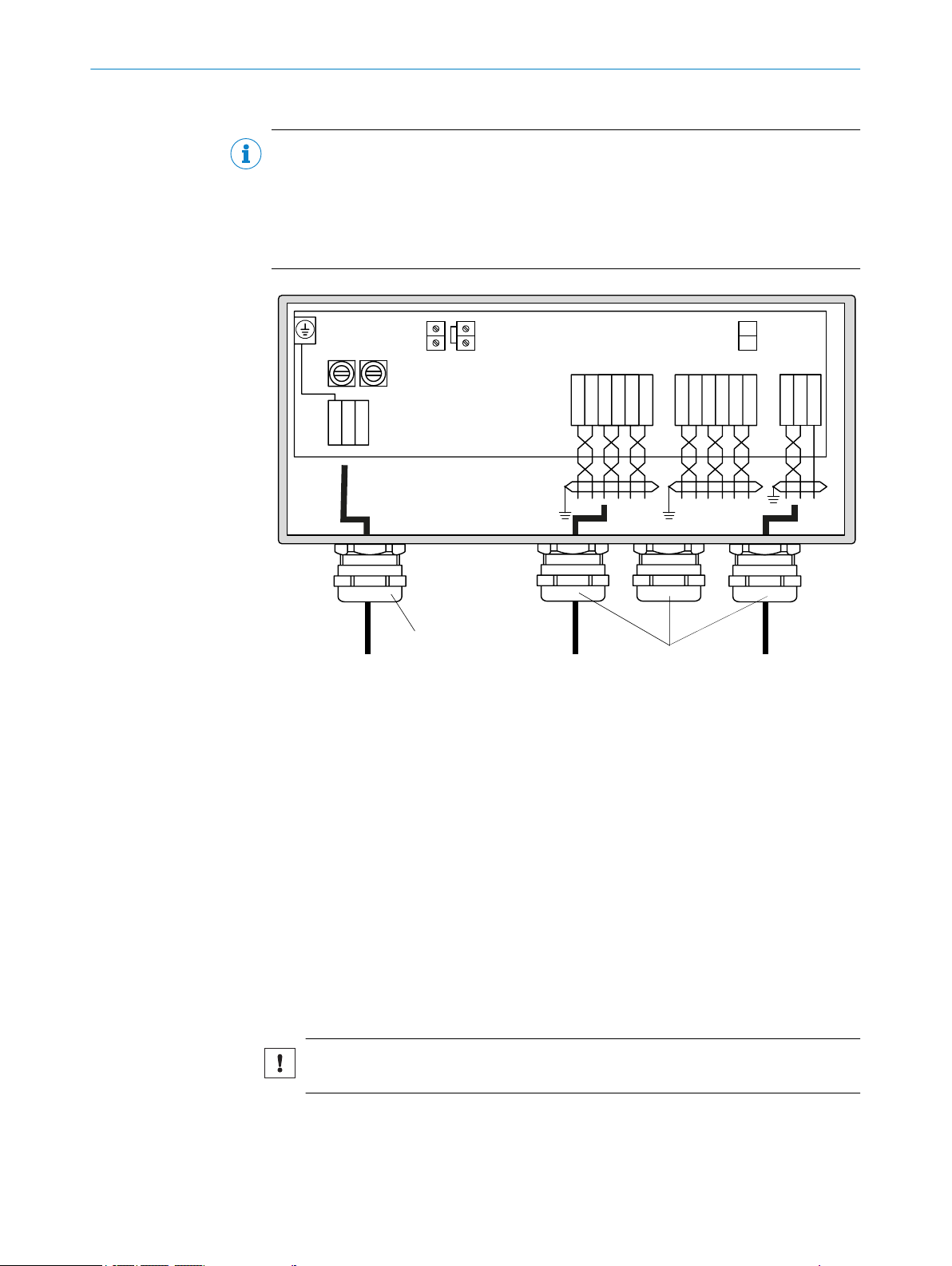
6.2 Connection overview................................................................................ 32
6.2.1 Lines......................................................................................... 33
6.2.2 Information on laying lines...................................................... 33
6.3 Connecting I/O interfaces........................................................................ 34
6.3.1 Leading the CAN bus line correctly through the PG screw
fitting........................................................................................ 34
6.3.2 Wiring the evaluation unit....................................................... 35
6.3.3 Customer wiring of the terminal box (optional)...................... 37
6.4 Connecting the SR-unit............................................................................. 38
6.5 Grounding conductor, evaluation unit..................................................... 38
7 Commissioning.................................................................................. 40
7.1 Safety information on commissioning..................................................... 40
7.2 Prerequisites for successful commissioning.......................................... 40
7.3 Overview of commissioning steps........................................................... 41
7.4 Material required ..................................................................................... 42
7.4.1 Material required - included in scope of delivery................... 42
7.5 Fitting the SR-unit on the purge air fixture of the measuring probe...... 43
7.6 Optical fine alignment for device versions for NH3 and HF measure‐
ment.......................................................................................................... 43
7.7 Optical fine alignment on the version for HCI measurement................ 45
7.8 Two types of zero point checks................................................................ 46
7.8.1 Selecting the ambient temperature range............................. 46
7.8.2 Carrying out zero adjust (on the measuring path free from
sample gas).............................................................................. 47
7.8.3 Zero point check with GPP measuring probe......................... 47
7.9 Repositioning the probe reflector............................................................ 48
7.10 Fitting the measuring probe on the flange with tube............................. 51
7.11 Putting the purge air unit into operation................................................. 52
7.12 Fitting the sender/receiver unit on the intermediate housing............... 52
7.13 Installing the weatherproof cover ........................................................... 53
7.14 Starting measuring operation.................................................................. 54
7.14.1 Operating states...................................................................... 55
7.14.2 Select the ambient temperature range.................................. 55
8 Operation............................................................................................ 56
8.1 Safety......................................................................................................... 56
8.1.1 Check before start-up.............................................................. 56
4
O PE R AT I NG IN S TR U CT I ON S | GM700 8022447/0000/2018-01 | SICK
Subject to change without notice
Page 5

CONTENTS
8.2 Operating and display elements (evaluation unit).................................. 56
8.3 Menu tree of the evaluation unit............................................................. 58
8.3.1 Menu tree Measuring.............................................................. 58
8.3.2 Menu tree Diagnosis............................................................... 58
8.3.3 Menu tree Parameter.............................................................. 59
8.3.4 Menu tree Calibration.............................................................. 61
8.3.5 Menu tree Maintenance.......................................................... 61
8.4 Operating using the serial interface........................................................ 62
8.4.1 Significance of command line elements................................ 62
8.4.2 Setting for serial interfaces..................................................... 62
8.4.3 Serial interface commands - Meas........................................ 62
8.4.3.1 Serial interface command - MEAS ........................ 62
8.4.4 Serial interface commands - Diag.......................................... 62
8.4.4.1 Table with warning messages................................ 62
8.4.4.2 Error messages Table ............................................ 63
8.4.4.3 View the device configuration................................ 63
8.4.4.4 Check the system state and configuration........... 63
8.4.4.5 Call up diagnostic data........................................... 63
9 Maintenance...................................................................................... 64
9.1 Safety......................................................................................................... 64
9.2 Maintenance plan..................................................................................... 65
9.2.1 Maintenance protocol.............................................................. 65
9.2.2 Expendable, wearing and spare parts.................................... 65
9.3 Preparatory work....................................................................................... 66
9.4 Removing the SR-unit from the intermediate housing........................... 66
9.5 Visual check.............................................................................................. 67
9.6 Cleaning the optical interfaces................................................................ 67
9.7 Cleaning the purge air unit....................................................................... 69
10 Troubleshooting................................................................................. 70
10.1 Safety......................................................................................................... 70
10.2 Monitoring and diagnostic system........................................................... 70
10.3 Device not functioning.............................................................................. 71
10.4 Evaluation unit not functioning................................................................ 71
10.4.1 Communication fault between evaluation unit and receiver 72
10.5 Error messages......................................................................................... 72
10.5.1 Error messages........................................................................ 72
10.5.2 Warning messages.................................................................. 74
10.6 Repairing inadequate purge air supply................................................... 74
10.7 Corrosion on flange.................................................................................. 75
11 Decommissioning............................................................................. 76
11.1 Safety information for decommissioning................................................ 76
11.2 Removing the device................................................................................ 77
11.3 Preparing the device ready for shipping.................................................. 77
8022447/0000/2018-01 | SICK OP E RA T IN G I N ST R UC T IO N S | GM700
Subject to change without notice
5
Page 6

CONTENTS
11.4 Environmentally compatible disposal ..................................................... 78
12 Technical data.................................................................................... 79
12.1 System: GM700........................................................................................ 79
12.2 Sender/receiver unit................................................................................ 80
12.3 GMP measuring probe.............................................................................. 80
12.4 GPP measuring probe............................................................................... 80
12.5 Evaluation unit: Sheet steel enclosure.................................................... 81
12.6 Evaluation unit: Cast metal enclosure..................................................... 82
12.7 Terminal box.............................................................................................. 82
12.8 Dimension drawings, sender/receiver unit ............................................ 83
12.9 Dimension drawings, open measuring probe (GMP).............................. 84
12.10 Dimension drawings GPP measuring probe (Gas Permeable Probe).... 85
12.11 Dimension drawing evaluation unit......................................................... 86
12.12 Dimension drawings: Mounting flange DN125....................................... 87
12.13 Dimension drawing terminal box............................................................. 87
12.14 Dimension drawing, purge air unit........................................................... 88
12.15 Dimension drawing, weatherproof cover, sender/receiver unit............. 88
13 Annex.................................................................................................. 89
13.1 Possible ambient temperatures............................................................... 89
13.1.1 Ambient temperature ranges (closed cell)............................. 89
13.2 User information on laser safety GM700................................................ 89
14 Index.................................................................................................... 91
6
O PE R AT I NG IN S TR U CT I ON S | GM700 8022447/0000/2018-01 | SICK
Subject to change without notice
Page 7

1 About this document
1.1 Function of this document
These Operating Instructions describe:
Device components
•
Installation
•
Operation
•
Maintenance work required for reliable operation
•
1.2 Scope of application
These Operating Instructions are only applicable for the measuring device described in
the product identification.
They are not applicable for other SICK measuring devices.
The standards referred to in these Operating Instructions are to be observed in the
respective valid version.
1.3 Target groups (and document structure)
ABOUT THIS DOCUMENT 1
This Manual is intended for persons installing, operating and maintaining the device.
Operation
The device may only be operated by qualified persons who, based on their device-spe‐
cific training and knowledge as well as knowledge of the relevant regulations, can
assess the tasks given and recognize the hazards involved.
Installation and maintenance
Skilled persons are required for installation and maintenance.
Please observe the information at the beginning of the respective Sections.
1.4 Further information
Operating Instructions of the purge air supply
•
Final inspection record
•
NOTE
Observe all supplied documents.
b
1.5 Data integrity
SICK AG uses standardized data interfaces such as, for example, standard IP technol‐
ogy, in its products. The focus here is on product availability and features.
SICK AG always assumes that the customer is responsible for the integrity and confi‐
dentiality of data and rights involved in connection with using the products.
In all cases, the customer is responsible for the implementation of safety measures
suitable for the respective situation, e.g., network separation, firewalls, virus protection
and patch management.
8022447/0000/2018-01 | SICK OP E RA T IN G I N ST R UC T IO N S | GM700
Subject to change without notice
7
Page 8
1 ABOUT THIS DOCUMENT
1.6 Symbols and document conventions
1.6.1 Warning symbols
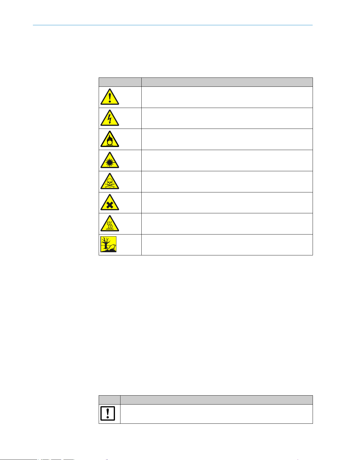
Table 1: Warning symbols
Symbol Significance
Hazard (general)
Hazard by voltage
Hazard by oxidizing substances
Hazard by laser radiation
Hazard by toxic substances
1.6.2 Warning levels / Signal words
DANGER
Risk or hazardous situation which will result in severe personal injury or death.
WARNING
Risk or hazardous situation which could result in severe personal injury or death.
CAUTION
Hazard or unsafe practice which could result in less severe or minor injuries.
Notice
Hazard which could result in property damage.
Note
Hazard by noxious substances
Hazard by high temperature
Hazard for the environment/nature/organic life
Hints
1.6.3 Information symbols
Table 2: Information symbols
Symbol Significance
8
O PE R AT I NG IN S TR U CT I ON S | GM700 8022447/0000/2018-01 | SICK
Important technical information for this product
Subject to change without notice
Page 9

Symbol Significance
Important information on electric or electronic functions
ABOUT THIS DOCUMENT 1
8022447/0000/2018-01 | SICK OP E RA T IN G I N ST R UC T IO N S | GM700
Subject to change without notice
9
Page 10
2 SAFETY INFORMATION
2 Safety information
2.1 Main operating information
Lifting and carrying
WARNING
Injury risk through incorrect lifting and carrying of the device
Injuries can occur due to the weight and projecting enclosure parts when the equip‐
ment tips over or drops.
Consider the device weight before lifting.
b
Observe the regulations for protective clothing (e.g., safety shoes, non-slip gloves).
b
Grip underneath the equipment when possible to carry it safely.
b
Do not use projecting parts on the device to carry the device.
b
Call in further personnel for assistance as required.
b
Use a hoist or transport equipment as an option.
b
Pay attention to the transport safety device.
b
Clear obstacles that could cause falls and collisions out of the way.
b
DANGER
Risk for system safety through work on the device not described in these Operating
Instructions
Carrying out work on the device not described in these Operating Instructions or associ‐
ated documents can lead to unsafe operation of the measuring system and therefore
endanger plant safety.
Only carry out the work on the device described in these Operating Instructions
b
and associated documents.
Laser radiation
WARNING
Eye injuries through laser radiation
The invisible laser beam within the SR-unit is not accessible when fitted. Observe the
following when the SR-unit of the device is swiveled open during installation work for
test purposes and the laser beam is activated:
Never look directly into the laser aperture when opening the SR-unit.
b
Laser protection class 1: Wear laser protection glasses despite low radiation.
b
Observe national valid limit values and standards that refer to these for industrial
b
safety.
Laser radiation, HF version
CAUTION
Pay attention to device software version
As the limit values of laser class 1 of the IEC 60825-1:2014-5 are neither exceeded in
single case malfunctions nor normal operation under consideration of the service and
measuring state, the device is classified as laser class 1. Prerequisite is using device
software 9105060_YEK0 or newer.
10
Laser class 1 of the IEC 60825-1:2014-5: Only use device software
b
9105060_YEK0 or a newer software version.
O PE R AT I NG IN S TR U CT I ON S | GM700 8022447/0000/2018-01 | SICK
Subject to change without notice
Page 11
SAFETY INFORMATION 2
DANGER
Important information for safe handling of the GM700 SR-unit on the device version
with HF measurement
For device software versions before 9105060_YEK0, a higher laser radiation might
occur.
Laser class 1 of the IEC 60825-1:2014-5: Only use device software
b
9105060_YEK0 or a newer software version.
Never look directly into the laser aperture when opening the SR-unit.
b
Always wear laser goggles or switch the device off during maintenance work.
b
Observe valid national limit values and respective standards for work safety.
b
NOTICE
Deviations of EN60825-1:2014-08 “Laser safety” from the Directive 2006/25/EC
The Directive has been adapted to cover changes in the health and safety regulation for
artificial optical radiation. Deviations occurred through changes in EN60825-1:2014-08
“Laser safety” from Directive 2006/25/EC.
Always observe the user information in the Annex of these Operating Instructions!
b
Escaping hot gas
DANGER
Risk of fire through hot gas escaping in installations with overpressure conditions
On installations with overpressure, the purge air hose can be severely damaged by
escaping hot gas and can catch fire depending on the temperature. On installations
with overpressure and gas temperatures over 200°C at the same time:
Regularly check the functionality of the reverse flow safeguard in the purge air fix‐
b
tures.
DANGER
Danger to life by leaking hot/toxic gases
Hot and/or noxious gases can escape during work on the gas duct, depending on the
plant conditions.
Work on the gas duct may only be performed by skilled technicians who, based on
b
their technical training and knowledge as well as knowledge of the relevant regula‐
tions, can assess the tasks given and recognize the hazards involved.
8022447/0000/2018-01 | SICK OP E RA T IN G I N ST R UC T IO N S | GM700
Subject to change without notice
11
Page 12
2 SAFETY INFORMATION
Electrical safety
WARNING
Endangerment of electrical safety during installation and maintenance work when the
power supply is not switched off
An electrical accident can occur during installation and maintenance work when the
power supply to the device and/or lines is not switched off using a power isolating
switch/circuit breaker.
b
b
b
b
DANGER
Endangerment of electrical safety through missing power isolating switch
An electrical accident can occur during installation and maintenance work when the
power supply to the device and/or lines cannot be switched off using a power isolating
switch/circuit breaker.
Before starting the work, ensure the power supply can be switched off using a
power isolating switch/circuit breaker in accordance with DIN EN 61010.
Make sure the power isolating switch is easily accessible.
An additional separation device is mandatory when the power isolating switch can‐
not be accessed or only with difficulty after installation of the device connection.
The power supply may only be switched on again after work completion or for test
purposes by the persons carrying out the work under consideration of the valid
safety regulations.
Ensure the power supply can be switched off using a power isolating switch/circuit
b
breaker in accordance with DIN EN 61010-1:2010.
An additional separation device is mandatory when the power isolating switch can‐
b
not be accessed or only with difficulty after installation of the device connection.
WARNING
Endangerment of electrical safety through power cables with incorrect rating
Electrical accidents can occur when the specifications for replacement of a removable
power cable have not been adequately observed.
Always observe the exact specifications in the Operating Instructions (Technical
b
Data Chapter) when replacing a removable power line.
Potential equalization
CAUTION
Device damage through incorrect or non-existing grounding
To avoid device damage, a correctly connected potential equalization is mandatory on
all system components with external ground connections in all operating conditions.
Connect a potential equalization on all planned points on the device components.
b
Ensure the potential equalization is connected during all work on the device
b
described in these Operating Instructions.
12
O PE R AT I NG IN S TR U CT I ON S | GM700 8022447/0000/2018-01 | SICK
Subject to change without notice
Page 13
Contamination caused by purge air failure
112 2
CAUTION
A faulty purge air supply can damage the measuring system
The measuring system can no longer be protected from contaminated sample gas and
is damaged.
When the purge air supply appears faulty, immediately perform all actions
b
described in these Operating Instructions.
Responsibility for system safety
NOTICE
Responsibility for system safety
The person setting the system up is responsible for the safety of the system in which
the device is integrated.
2.2 Warning information on the device
GM700 SR-unit
SAFETY INFORMATION 2
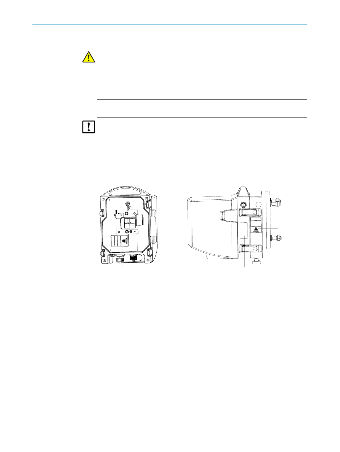
Figure 1: Warning information on the sender/receiver unit
SR-unit, front side
1 Danger sign: Laser radiation
2 Type plate GM700
SR-unit, right side
1 Danger sign: Laser radiation
2 Type plate GM700
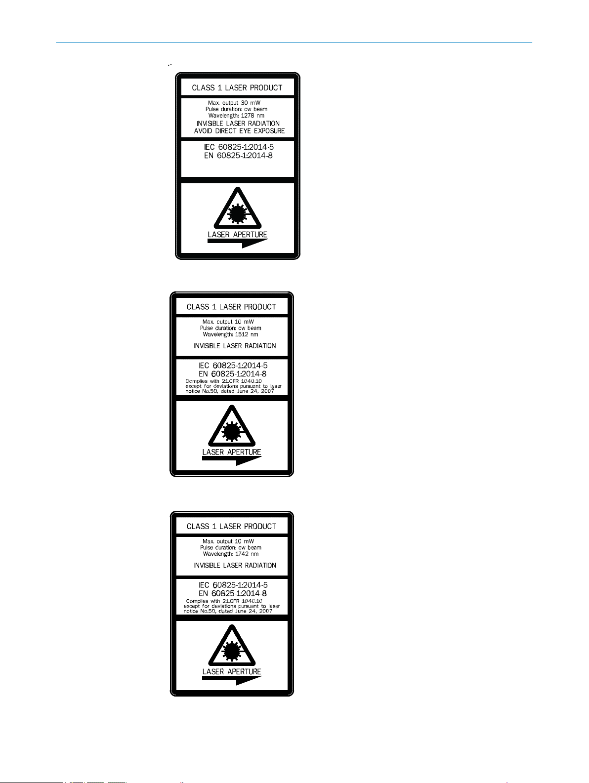
Laser sign
The wavelength of the laser varies for the respective measuring components (NH3, HF,
HCl). The maximum laser output at the optical interface depends on the respective
measuring component and is shown on the laser warning sign.
8022447/0000/2018-01 | SICK OP E RA T IN G I N ST R UC T IO N S | GM700
Subject to change without notice
13
Page 14
2 SAFETY INFORMATION
Figure 2: Laser sign for HF measurement
14
Figure 3: Laser sign for NH3 measurement
Figure 4: Laser sign for HCI measurement
O PE R AT I NG IN S TR U CT I ON S | GM700 8022447/0000/2018-01 | SICK
Subject to change without notice
Page 15

2.3 Intended use
The device serves exclusively for emission and process monitoring of gases in industrial
plants.
The device measures continuously directly in the gas duct (in-situ).
2.4 Responsibility of user
Designated users
see "Target groups (and document structure)", page 7.
Correct project planning
Basis of this Manual is the delivery of the device according to the preceding
•
project planning (e.g., based on the SICK application questionnaire) and the rele‐
vant delivery state of the device (see delivered System Documentation).
w
Contact SICK Customer Service if you are not sure whether the device corre‐
sponds to the state defined during project planning or to the delivered system
documentation.
Special local conditions
SAFETY INFORMATION 2
In addition to the information in these Operating Instructions, follow all local laws, tech‐
nical rules and company-internal operating directives applicable wherever the device is
installed.
Read the Operating Instructions
Read and observe these Operating Instructions.
b
Observe all safety instructions.
b
If anything is not clear: Please contact SICK Customer Service.
b
Document retention
Must be kept for reference.
b
Must be passed on to new owners.
b
8022447/0000/2018-01 | SICK OP E RA T IN G I N ST R UC T IO N S | GM700
Subject to change without notice
15
Page 16
3 PRODUCT DESCRIPTION
3 Product description
3.1 Product identification
Product name GM700
Device version Measuring Probe Version
Manufacturer SICK AG
Type plates Measuring Probe Version
3.2 Product characteristics
■
The device serves for continuous measurement of gas concentrations in industrial
plants
■
For application with high water ratios, i.e. waste incineration, we offer a specific
version, the GM700-04 or GM700-07.
■
The device is an in-situ measuring system which means measuring is done directly
in the gas carrying duct
■
Measuring components: HF, HCI, NH3, NH3 + H2O, HCI + H2O
■
Measuring principle: Diode laser spectroscopy (TDLS)
Erwin-Sick-Str. 1 · D-79183 Waldkirch · Germany
Sender/receiver unit: On right side
•
On purge air fixture: On tube
•
3.3 Device variants
Variants Measured components
GM700-02 HF
GM700-03 HCI
GM700-04 NH3, high humidity
GM700-05 NH
GM700-07 NH3 / H2O, high humidity
GM700-08 HCI / H2O
GM700-09 NH3 / H2O
3.4 Options
•
•
•
•
3
Terminal box: For CAN bus with 24 V power supply.
The optional terminal box is available for distances between SR-unit and EvU >4
meters via a CAN bus cable provided by the customer.
Cover plate: For the purge air fixture of the SR-unit.
To maintain purge air supply in cases where this must remain in operation at the
measuring point when the SR-unit is dismounted.
Weatherproof cover: Required for installation outdoors
Air heater for purge air supply: For special application conditions to prevent con‐
densate. An air heater is required when the difference between gas temperature
and dew point temperature is too small. The following practical rule of thumb
serves as guideline:
Gas temperature [°C] – dew point temperature [°C] < abs. humidity [Vol.-%].
Values are compared without considering the units of measure.
16
O PE R AT I NG IN S TR U CT I ON S | GM700 8022447/0000/2018-01 | SICK
Subject to change without notice
Page 17
3.5 Layout and function
1
2 3
1
4
5
6
6
PRODUCT DESCRIPTION 3
3.6 Purge air unit
Figure 5: GM700 layout (version representation)
Sender/receiver unit GM700 (SR-unit)
1
Purge air fixture
2
Flange with tube
3
Evaluation unit
4
Purge air unit
5
CAN lines
6
Function
The device serves for continuous measurement of gas concentrations in industrial
•
plants.
The device is an in-situ measuring system which means measuring is done directly
•
in the gas carrying duct.
Measuring components: see "Device variants", page 16.
•
Measuring principle: Diode laser spectroscopy (TDLS) (laser protection class 1).
•
To safeguard measuring reliability, a permanent air flow (optics purge air) keeps
•
the optics free from soot and dust particles.
This protects the front window of the SR-unit and the reflector in the measuring
•
probe against contamination and high gas temperatures
The purge air is blown into the gas duct through the “flange with tube”.
•
Further information on the purge air unit, see Operating Instructions of the purge air
unit.
8022447/0000/2018-01 | SICK OP E RA T IN G I N ST R UC T IO N S | GM700
Subject to change without notice
NOTE
17
Page 18

3 PRODUCT DESCRIPTION
3.7 Check cycle
Cyclic check cycle for zero and sensitivity checks
Start a check cycle via
•
•
Purpose of check cycle
■
Check cycle procedure
The measuring sequence to determine the zero and check point is performed. The digi‐
tal input uses a falling edge for triggering, i.e. performance of a check cycle is sup‐
pressed as long as the signal is high (e.g., for control purposes).
Signaling
“Function control” (relay 3) is signaled per digital output during output of the zero and
check point.
Timer trigger: Configurable 0 ... 1440 minutes (= 1 day), see menu “Settings /
Check Cycle”
External digital input signal (Di 1)
Checking the zero point and span point without feeding span gases.
Output
The output runs for 90 seconds each for the zero point followed by the check point.
Unit and scaling for the current zero point according to the settings.
•
Check or span point is displayed as percentage scaled to 70% of the measuring
•
range.
The same calculation method is used for the deviation as for the gas concentration with
the exception of correction factors which result from a gas adjustment as well as cus‐
tomer correction factors from menu PAR/SETTINGS / REGRESS. FUNCT. During the
check cycle output, the zero and span point are displayed in the lower display line paral‐
lel to the analog output. These can be viewed in menu DIAG/CHECK VALUES/<GAS> for
subsequent checks. Prerequisite is that the output has already been made via an ana‐
log output.
Deviations
A warning message is output, e.g., “AO1 NH3 ZEROPoint” when the zero or check point
deviation is above 2% of the upper display limit of an analog output.
The warning message remains until the next check cycle output is within the tolerance.
3.8 GMP and GPP measuring probes
The measuring probe included in the scope of delivery was defined during project plan‐
ning in accordance with the application requirements.
18
This Table shows an overview of the features of the different measuring probes. All
measuring probe versions are compatible with all SR-units. The SR-unit is calibrated to
the respective probe length before delivery.
Table 3: Measuring probes
Measuring probe GMP (open measuring probe) GPP (for dry gases)
Version Measuring path open in flow
direction; purge air guidance
with outlet aligned 90° to gas
flow
O PE R AT I NG IN S TR U CT I ON S | GM700 8022447/0000/2018-01 | SICK
Gas diffusion probe with
ceramic filter, for dry sample
gas
Subject to change without notice
Page 19

pen Close
2
5
7
6
4
3
1
4
PRODUCT DESCRIPTION 3
Measuring probe GMP (open measuring probe) GPP (for dry gases)
Max. gas temperature 250°C 430°C
Gas test according to EPA reg‐
ulation
Purge air supply required Yes No
Optical interface heating in
measuring probe
Sample gas flow velocity 1 ... 40 m/s < 40 m/s
Suitable for wet sample gas Yes No
Maximum duct pressure ±120 hPa, depending on
Measurable components NH3, HF, HCl NH3, HCl
System response time (T90) > 5 s > 120 s
Duct diameter > 360 mm > 300 mm
Dust concentration < 2 g/m3 in operating state < 30 g/m3 in operating state
Probe lengths available "Dimension drawings, open measuring probe (GMP)",
Active measuring paths avail‐
able [mm]
No Yes
No Yes, with integrated control
±120 hPa
purge air supply
page 84 and "Dimension drawings GPP measuring probe
(Gas Permeable Probe)", page 85.
250/500/750/1000/1250 250/500/750/1000
3.8.1 GMP measuring probe in detail
Figure 6: GMP measuring probe description
1
2
3
4
5
6
7
Reflector unit
PT1000 temperature sensor
Purge air outlet: Air outlet in the duct 90° to gas flow direction (directed purge air)
Locking device for opening between measuring probe and SR-unit
Light beam, sender-reflector
Purge air connection
CAN connection
8022447/0000/2018-01 | SICK OP E RA T IN G I N ST R UC T IO N S | GM700
Subject to change without notice
19
Page 20
3 PRODUCT DESCRIPTION
3.8.1.1 Gas connection for sample gas sampling on purge air fixture of GMP measuring probe
For the reference measurement, sample gas can be extracted from the gas duct via a
gas sampling valve on the purge air fixture of the GMP measuring probe.
Figure 7: Gas sampling valve on the GMP measuring probe
Gas sampling screw fitting
1
NOTE
The reference measurement is not part of maintenance tasks carried out by the cus‐
tomer.
3.8.2 GPP gas diffusion probe in dry or wet version
Project planning information: There are two versions of the GMP measuring probe that
differ in the filter used. This supports differing application areas regarding the moisture
content of the sample gas.
Characteristics
Suitable for higher dust contents than the GMP probes.
•
For EPA-conform audit measurement.
•
For applications with low flow velocities or varying flow profiles.
•
Integrated sensors
Temperature sensor PT 1000: Continuously measures the media temperature on
•
the active measuring path of the probe
Pressure sensor
•
The measured data are transferred via the CAN bus interface of the measuring
•
probe and can then be displayed on the evaluation unit.
20
Figure 8: GPP measuring probe description
Reflector unit
1
O PE R AT I NG IN S TR U CT I ON S | GM700 8022447/0000/2018-01 | SICK
Subject to change without notice
Page 21
Ceramic filter (gas permeable)
2
PT1000 temperature sensor
3
Light beam, sender-reflector
4
CAN connection
5
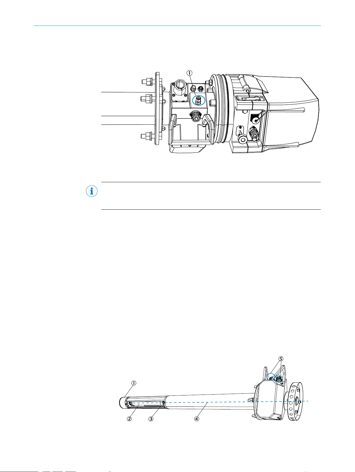
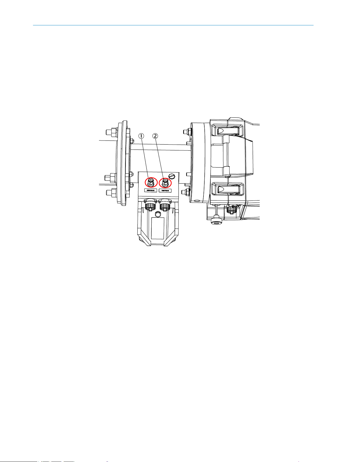
3.8.2.1 GPP measuring probe gas connections for zero and span gas
Two gas inlets are located on the purge air fixture of the GPP measuring probe for the
zero point test.
PRODUCT DESCRIPTION 3
Figure 9: Gas inlets on the measuring probe
Zero gas connection
1
Test gas connection
2
8022447/0000/2018-01 | SICK OP E RA T IN G I N ST R UC T IO N S | GM700
Subject to change without notice
21
Page 22
4 TRANSPORT AND STORAGE
4 Transport and storage
4.1 Transport protection
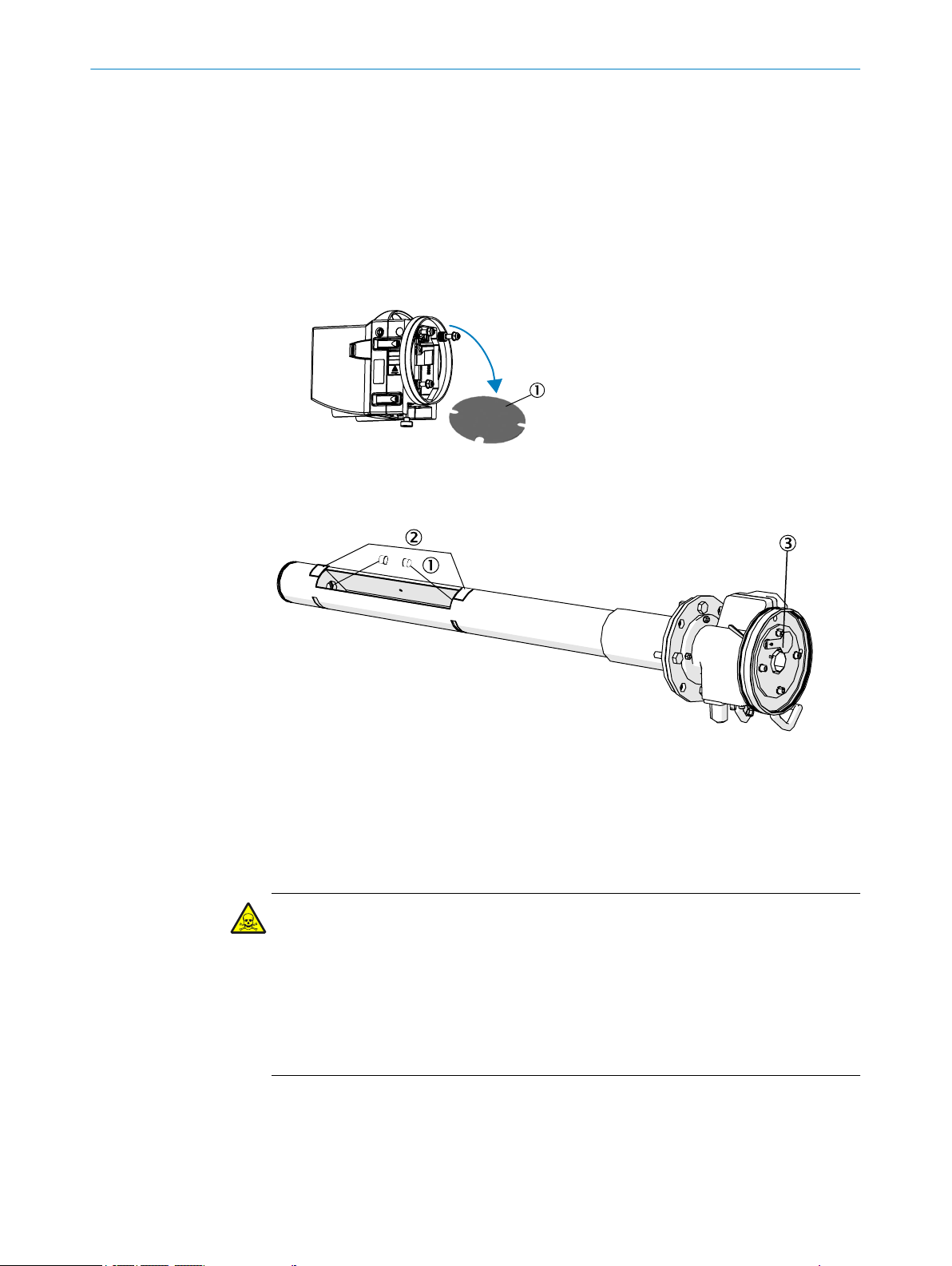
Removing the transport safety device on the SR-unit
1 Open the lock and swivel the flange fixture open.
2 Check the transport safety device for damage.
3 Remove the transport safety devices (see Figure).
4 Store the transport safety device.
Figure 10: Transport safety device on the SR-unit
Remove the front cover of the sender/receiver unit
1
4.2 Storage
Figure 11: Transport safety device on the GMP measuring probe
2 plastic protective caps to cover the optics
1
Remove the protective stickers
2
Set the locking device to the “close” position
3
DANGER
Risk to health through contaminated measuring probe
Depending on the composition of the gas in the measuring channel, the measuring
probe could be contaminated with substances which could result in serious health
damage.
Decontaminate the measuring probe before storage.
b
Wear the specified protective clothing for all work with a contaminated measuring
b
probe.
Clean all components of the measuring system with slightly damp cleaning cloths.
b
Use a mild cleaning agent here.
Protect the openings of the SR-unit and measuring probe from atmospheric influ‐
b
ences, preferably with the original transport safety devices.
22
O PE R AT I NG IN S TR U CT I ON S | GM700 8022447/0000/2018-01 | SICK
Subject to change without notice
Page 23

TRANSPORT AND STORAGE 4
Pack all components for storage or transport. Preferably use the original packing.
b
Store all components of the measuring system in a dry, clean room.
b
8022447/0000/2018-01 | SICK OP E RA T IN G I N ST R UC T IO N S | GM700
Subject to change without notice
23
Page 24
5 MOUNTING
5 Mounting
5.1 Assembly information
Project planning for measuring channel
NOTICE
Observe information in Chapter “Main operating information”.
Correct installation
DANGER
Risk for system safety through work on the device not described in these Operating
Instructions
Carrying out work on the device not described in these Operating Instructions or associ‐
ated documents can lead to unsafe operation of the measuring system and therefore
endanger plant safety.
Only carry out the work on the device described in these Operating Instructions
b
and associated documents.
WARNING
Risk of injury when the device drops down
The weight of the device can cause it to drop down and cause injuries during the work
described in this Chapter.
Carry out assembly work on parts of the device together with another person when
b
necessary.
5.2 Tools required
Tools Part No. Required for
Adjustment device 2034121 Alignment of "flanges with tube"
19 mm jaw wrench Flange screw fitting
Screwdriver Connections
Allen key Connections
5.3 Preparing the measuring point
The operator is responsible for preparing the measuring point
NOTICE
Basis for determining the measuring point:
24
Preceding project planning (e.g., based on the SICK application questionnaire)
•
Final inspection specifications for device
•
Regulations of local authorities
•
Responsibility of the operator:
The operator is responsible for preparing the measuring point
Determination of measuring point (e.g. determining a representative sampling
•
point)
Preparing the measuring point (e.g. load capacity of welded on flange)
•
O PE R AT I NG IN S TR U CT I ON S | GM700 8022447/0000/2018-01 | SICK
Subject to change without notice
Page 25
MOUNTING 5
5.4 GM700 scope of delivery
Check the scope of delivery according to the order confirmation/delivery note.
Ensure the specified supply voltages correspond with the plant conditions.
5.5 Installation sequence
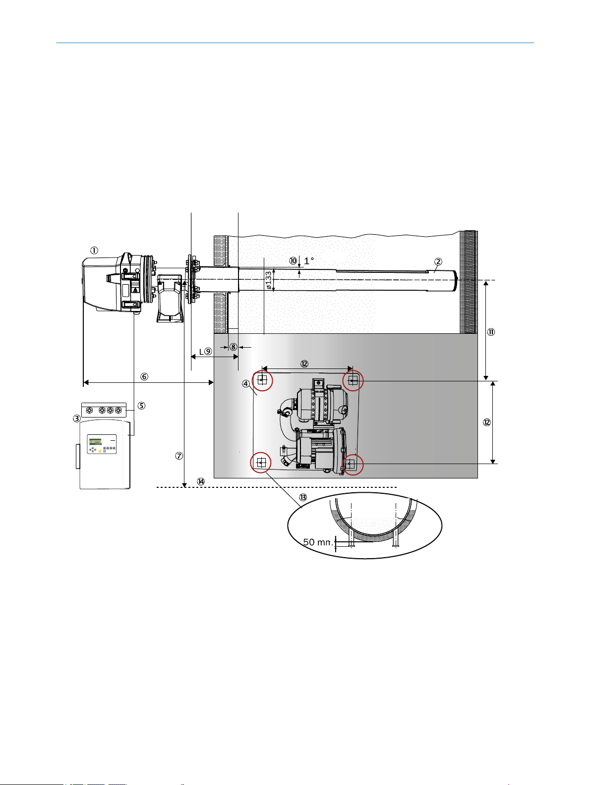
5.5.1 Installation example
Carry out assembly according to the project planning and the Inspection protocol. The dimensions specified in the
drawings are guidelines and can deviate strongly from the project planning.
Figure 12: Assembly example, all dimensions in mm
Sender/receiver unit (SR-unit)
1
Measuring probe (GMP version)
2
Evaluation unit (EvU) and optional terminal box
3
Purge air unit
4
Dimensions
Max. distance SR-unit - EvU: 4 m CAN line
5
When using a terminal box, extension up to 1000 m overall length
Duct wall - SR-unit: Depending on flange with tube length
6
a Consider space required for fitting and removing the measuring probe in the duct!
Minimum clearance (center) - working platform: 1300 - 1500 mm
7
Min. flange length in gas duct: 30 mm
8
L = flange with tube length: Standard 240 mm
9
8022447/0000/2018-01 | SICK OP E RA T IN G I N ST R UC T IO N S | GM700
Subject to change without notice
25
Page 26
5 MOUNTING
Angle of flange inclination: Max. 1°
ß
Minimum clearance flange (center) to purge air supply: >700 mm
à
Horizontal and vertical clearance of fastening drill holes - purge air supply assembly plate: 470 mm
á
Purge air unit fastening: 50 mm protrusion for circular duct cross-section
â
Miscellaneous
Working platform
ã
5.5.2 Overview of installation steps (duct-side preparation)
Table 4: Installation steps overview
Step Procedure Reference
1 Fit flange with tube. "Installing the flange with tube",
page 26.
2 Fit control unit. "Installing the control units", page 27.
3 Optional: Fit terminal box. "Installing the terminal box (option)",
page 30.
4 Fit purge air unit or units. "Installing the purge air unit",
page 30.
5.5.3 Installation preparation for the purge air unit
NOTE
Observe the maximum line length between purge air unit and measuring device accord‐
ing to project planning.
NOTE
For information on installing the purge air unit, see the Operating Instructions of the
purge air unit.
CAUTION
Risk of purge air failure when purge air pressure too low
The purge air cannot enter the gas duct when the purge air pressure is too low. This can
lead to a purge air deficit which will cause the device to fail.
Pay attention to the correct purge air pressure during project planning.
b
If you have questions concerning the purge air pressure, contact SICK Customer
b
Service or your local SICK representative.
5.5.4 Installing the flange with tube
DANGER
Hazard through hot, explosive or toxic flue gases
Hot and/or noxious gases can escape during installation work on the gas duct, depend‐
ing on the plant condition.
26
Work on the gas duct may only be performed by skilled persons who, based on
b
their technical training and knowledge as well as knowledge of the relevant regula‐
tions, can assess the tasks given and recognize the hazards involved.
O PE R AT I NG IN S TR U CT I ON S | GM700 8022447/0000/2018-01 | SICK
Subject to change without notice
Page 27
1
200
18
4
5
°
MOUNTING 5
CAUTION
Device damage through incorrect/missing insulation of the duct when the measuring
channel is hot
When the gas duct is hot, insulate the duct and flanges so that the device is pro‐
b
tected from high temperatures.
Installing the flange with tube on the gas duct
1 Cut openings on the gas duct for the flange with tube.
2 Insert the flange with tube. Pay attention to the following:
The "Top" marking must point upwards vertically, irrespective of the gas duct
°
angle.
The tube must project at least 30 mm into the gas duct
°
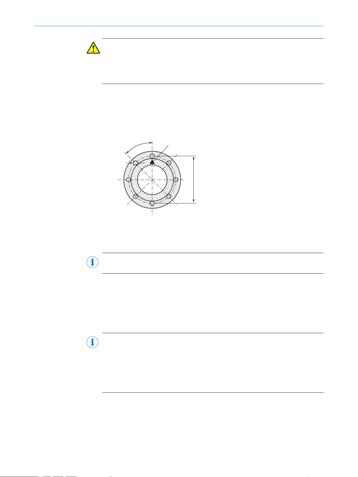
Figure 13: "Top" marking on flange with tube
1
3 Attach the flange with tube.
NOTE
The measuring probe must not collide with other devices or fittings.
4 Tilt the tube slightly downwards (max. 1°) to allow any condensate to drain off.
5 Now fix the flange with tube properly to the gas duct. Make sure that the alignment
of the flange does not change.
6 If necessary, attach duct insulation to protect the device from heat.
5.5.5 Installing the control units
NOTE
The following criteria must be observed when selecting the installation location of the
control unit:
Good access
•
Sufficient space to open the swivel door of the evaluation unit
•
Protected from weather
•
Even, vertical installation surface
•
Marking “Top”
8022447/0000/2018-01 | SICK OP E RA T IN G I N ST R UC T IO N S | GM700
Subject to change without notice
Dimension drawings, see "Dimension drawing evaluation unit", page 86.
27
Page 28
160
322
90
82
1
2
3
MOUNTING
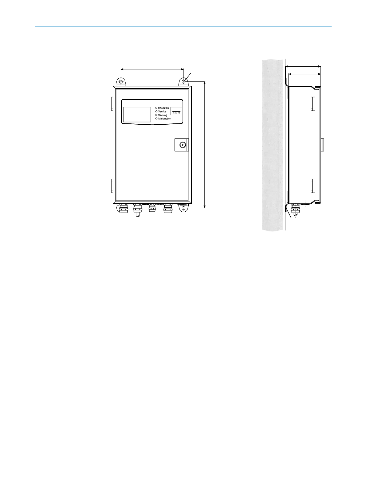
5
Control unit version with sheet metal enclosure
Figure 14: Fitting the control unit (sheet metal housing version)
4 x mounting holes: ø 7.2 mm
1
Mounting surface
2
Fastening brackets
3
1 Bore the mounting holes according to the drilling plan.
2 Fasten the control unit to the four fastening brackets with M8 screws.
28
O PE R AT I NG IN S TR U CT I ON S | GM700 8022447/0000/2018-01 | SICK
Subject to change without notice
Page 29

Control unit version with cast metal enclosure
117.5
330
235
MOUNTING 5
Figure 15: Fitting the control unit (cast metal version)
1 Bore the mounting holes according to the drilling plan.
2 Fasten the control unit to the three mounting holes with M8 x 20 bolts.
NOTE
The mounting holes are accessible with the swivel door open.
5.5.5.1 Install the control unit away from the SR-unit
NOTE
The total length of the CAN bus connections may be up to 1000 m.
A terminal box with 24 V power supply unit is used to install the control unit at a longer
distance from the SR-unit. This is connected to the SR-unit using the delivered CAN bus
line (4 m).
A suitable customer 6-pole line (twisted pair wires and shielded), suitable for CAN bus
applications, leads to the control unit. The total length of the CAN bus lines, including
the one to the reflector, may be up to 1000 m. When performing maintenance or ser‐
vice, it must be possible to deinstall the control unit temporarily and connect it directly
to the SR-unit at the measuring point.
Further information on laying lines, see "Information on laying lines", page 33.
8022447/0000/2018-01 | SICK OP E RA T IN G I N ST R UC T IO N S | GM700
Subject to change without notice
29
Page 30

1
1
5 MOUNTING
5.5.6 Installing the terminal box (option)
Install the terminal box with 24 V power supply unit in the vicinity of the measuring
•
point.
Fasten the enclosure on both mounting holes.
•
The line length available from the terminal box to the SR-unit is 4 m.
•
NOTE
Take the empty conduits laid for the prefabricated lines during onsite preinstallation
into account.
Figure 16: Mounting fixtures of the terminal box
Mounting holes Ø 5 mm
1
5.5.7 Installing the purge air unit
NOTE
Purge air hose to the device according to project planning.
NOTE
For information on installing the purge air unit, see the Operating Instructions of the
purge air unit.
30
O PE R AT I NG IN S TR U CT I ON S | GM700 8022447/0000/2018-01 | SICK
Subject to change without notice
Page 31

6 Electrical installation
6.1 Electrical installation safety information
Electrical safety
WARNING
Endangerment of electrical safety during installation and maintenance work when the
power supply is not switched off
Before starting the work on the device, ensure the power supply can be switched
b
off using a power disconnector switch/circuit breaker in accordance with DIN EN
61010-1:2010.
Make sure the power disconnector switch is easily accessible.
b
An additional disconnecting device is mandatory when the power disconnector
b
switch cannot be accessed or only with difficulty after installation of the device
connection.
After completion of the work or for test purposes, the power supply may only be
b
activated again by authorized personnel complying with the safety regulations.
WARNING
Endangerment of electrical safety through power cable with incorrect rating
Electrical accidents can occur when the specifications for replacement of a power line
have not been adequately observed.
ELECTRICAL INSTALLATION 6
Always observe the exact specifications in the Operating Instructions (Technical
b
Data Chapter) when replacing a power line.
DANGER
Danger of electrical accidents
Incorrect performance of electrical work could result in serious electrical accidents.
Only let the work described in the following be carried out by electricians familiar
b
with potential hazards.
CAUTION
Risk of device damage
Electronic components are accessible when the enclosure is open. The circuit board
can be severely damaged when a contact is not grounded when the power supply is
switched on.
First switch the power supply on when the sender/receiver unit and the control
b
unit are closed.
NOTICE
Observe connection values for power supply
The evaluation unit is configured to 230 V AC on delivery.
Plug the respective bridges for 115 V AC as shown on the connection plate of the
b
evaluation unit.
8022447/0000/2018-01 | SICK OP E RA T IN G I N ST R UC T IO N S | GM700
Subject to change without notice
31
Page 32

1
2
3
4
1
1
5
5 m
6 7
max. 100 m
3
2
0,8 m
4 m
6 ELECTRICAL INSTALLATION
CAUTION
Device damage through short circuit on the device
The internal electronics can be damaged when signal connections are established and
the power supply is switched on. This is also valid for plug connections.
Disconnect the GM32 Ex and any connected devices from the voltage supply.
b
6.2 Connection overview
32
Figure 17: Overview of electrical connections, GM700
Power supply 230 /115 V AC; 50/ 60 Hz
1
•
EvU: 3 x 0.75 mm
•
SLV: 4 x 1.5 mm
•
Terminal box: 4 x 1.5 mm
CAN line standard, in scope of delivery
2
Optional: Can bus line extension:
3
•
EvU - terminal box, ready for connection, 15 m
•
Terminal box - SR-unit (from customer) up to 100 m
Optional: Terminal box:
4
To extend the CAN bus connection (1 x 2 x 0.5 mm2, twisted pair, shielded)
SLV4 filter monitoring (standard for GMP measuring probe):
5
•
2 x 0.6 mm2, on pressure controller with flat pin bushings
•
6.3 x 0.8 mm (DIN 46247) pressure connection
•
2 m and 3 m extensions possible
Inputs (6 x 0.5 mm2):
6
O PE R AT I NG IN S TR U CT I ON S | GM700 8022447/0000/2018-01 | SICK
2
2
2
Subject to change without notice
Page 33

6.2.1 Lines
ELECTRICAL INSTALLATION 6
•
3 x digital inputs
•
2 x analog inputs
Outputs (6 x 0.5 mm2):
7
•
3 x digital outputs
•
3 x analog outputs
Table 5: PG screw fittings
Line opening size Line diameter (clamp‐
ing range)
PG9 4-8 mm 4 Nm SW17(GG9) 1
PG11 5-10 mm 8 Nm SW20(PG11) 1
PG13.5 6-12 mm 10 Nm SW22(PG13.5) 3
Table 6: Technical data, lines
Lines Remark
Power supply From customer: 3 x 1.5 mm
Power supply of control unit From customer: 3 x 1.5 mm
Control unit - sender/receiver unit with
connecting hose
Pressure/temperature input From customer
Service interface From customer, RS232
Inputs/outputs From customer: Terminal connections: 6 x 0.75
Control unit - temperature sensor From customer
Control unit - pressure sensor From customer
Tightening torque Key width Qty.
2
2
In accordance with project planning
5 m
•
10 m
•
2
mm
6.2.2 Information on laying lines
CAN bus
Installation location of the control unit close to the measuring point :
Control unit - SR-unit connection: 4 m CAN bus line (in scope of delivery).
•
No extra installation effort.
•
Fitting the control unit at a distance
Terminal box with a 24 V power supply unit (available from SICK).
•
Terminal box - SR-unit: 4 m CAN bus line (in scope of delivery).
•
Terminal box - control unit: Suitable 6-pole cable for CAN bus applications (pro‐
•
vided by customer).
The total length of the CAN bus connections may be up to 1000 m.
•
When performing maintenance or service, it must be possible to deinstall the con‐
•
trol unit temporarily and connect it directly to the SR-unit at the measuring point.
Laying the cables
Provide adequate cable lengths at the connection points.
•
Do not lay power supply and signal lines immediately next to each other.
•
Protect open ends of preinstalled cables against weather effects until device
•
installation.
8022447/0000/2018-01 | SICK OP E RA T IN G I N ST R UC T IO N S | GM700
Subject to change without notice
33
Page 34

6 ELECTRICAL INSTALLATION
Install separate power supply cables and circuit breakers for:
•
– Purge air units. Additionally install motor circuit breakers and protective
phase failure switches.
– Control unit.
Install easily accessible cable ducts or empty conduits for the prefabricated cables
•
or those delivered with the system, marked with one or two plug-in connectors.
Approx. 2 m cable lengths each should be available at the measuring point for
later maintenance work on the measuring system when dismounted from the duct.
Wire cross-section specifications are recommendations from which cables for ana‐
•
log and digital signals can slightly deviate (not however for the CAN bus connec‐
tions and/or power supply cables).
Start with the system internal connections of the device.
•
Status and signal cables from the control unit to the connection terminals of the
•
customer's status/message devices can be added later as required.
6.3 Connecting I/O interfaces
1 Route the data lines through the M screw fittings.
2 Connect the data line.
NOTE
The analog input assignment shown in the following Chapter is the factory setting and
may not be modified.
6.3.1 Leading the CAN bus line correctly through the PG screw fitting
CAUTION
Risk of injury when touching the cable gland
The temperature on the cable glands can be >60 °C.
Let the device cool down before performing work on the CAN screw fitting.
b
34
O PE R AT I NG IN S TR U CT I ON S | GM700 8022447/0000/2018-01 | SICK
Subject to change without notice
Page 35

ELECTRICAL INSTALLATION 6
Figure 18: CAN bus line fitted correctly (shown on the EvU)
PG screw fitting on the evaluation unit
1
CAN bus line
2
Shielding of CAN cable
3
PG screw fitting fitted in the control unit
4
6.3.2 Wiring the evaluation unit
1. Check that the power supply is switched off.
2. Open enclosure door of evaluation unit.
3. Check that the power supply has been installed in accordance with the project planning (under consideration
of national requirements).
4. Connect protective conductor (PE) to the terminal on the enclosure base.
5. Lead signal lines for inputs and outputs through the PG screw fitting on the housing base of the EvU.
6. Wire the evaluation unit,
7. When using a CAN line provided by the customer, connect the wires to the “Sensor” terminal strip. Do not
connect +24 V and GND (ground).
8022447/0000/2018-01 | SICK OP E RA T IN G I N ST R UC T IO N S | GM700
Subject to change without notice
35
Page 36

+ – + – + –
+ – + – + –
+ – + – + –
PE
N
L1
PE N L1
V
4
2+
T
H
NA
C
L
N
A
C
T
V
4
2+
+ – + – + –
115/230 V AC;
50/60 Hz
(3 x 1.52)
+ – + – + –
1 2
1 2 3
Power
+5V +24V
Power CAN
+24V
+ – H L GND
Digital inAnalog in
0... 20mA
100 100 100
40...60Hz
230V
or
115V
AO1 AO2 AO3DI1 DI2 DI3
AI1 AI2 AI3
Sensor
DO1 DO2 DO3
Digital out
AC/DC 48V 30VA 1A
Analog out
0.. 20mA
Sensor
Fuse 2.5 AT 250V
PE N L1
contrast
T p
Enter meas
diag par cal maint
Operation
Service
Warning
Malfunction
GMA700
Evaluation Unit
PROFIBUS
1
2
3
4
5
6
7
! " §
8
6 ELECTRICAL INSTALLATION
Figure 19: Electrical wiring of evaluation unit GMA700
1
2
3
4
5
6
7
8
Operating elements board
Connections board
Plug this bridge for 115 V or 120 V pow supply
CAN H + L, twisted pair, shielded. Connection for GM700 SR-unit or terminal box
Analog inputs: 0 ... 20 mA (6 x 0.52)
Digital inputs: Potential-free contacts (6 x 0.752)
Analog outputs: 0 ... 20 mA (6 x 0.752)
Digital outputs: 48 V AC/DC; 60 VA, 1 A (6 x 0.752)
! Failure (NC contact)
" Maintenance request (NO contact)
§ Function check (NO contact)
36
O PE R AT I NG IN S TR U CT I ON S | GM700 8022447/0000/2018-01 | SICK
Subject to change without notice
Page 37
6.3.3 Customer wiring of the terminal box (optional)
Fuse 2.5 AT
230/115 V AC
40 … 60 Hz
1
250 V
2
3
2
1
PENL1
6
3
5 4
PG 13.5
PG 13.5
CAN- L
+24
GND
CAN- H
CAN GN D
NC
5
4
3
2
1
6
CAN- L
CAN- H
CAN GN D
3
2
1
CAN- L
+24
GND
CAN- H
CAN GN D
5
4
3
2
1
NC
6
CAN
Terminator
NOTE CAN BUS WIRING PROJECT PLANNING
The following options are available for wiring the CAN bus connection between SR-unit
and control unit:
Standard cable, 4 m, prefabricated.
•
Terminal box with prefabricated 4 m long cable to SR-unit; a customer line is used
•
to connect to the control unit.
ELECTRICAL INSTALLATION 6
Figure 20: Customer wiring for terminal box
Power supply 115 V / 230 V
1
Operating voltage selection: 115 V / 230 V
2
CAN terminator
3
Sensor CAN connection 1*: Prefabricated line to SR-unit with plug, 4 m long
4
Sensor CAN connection 2
5
Evaluation unit CAN connection
6
*
Only one of the two CAN connection terminal strips available is required for the device
Connecting the CAN line to the terminal box
1. Check that the power supply is switched off.
2. Connect bridge (jumper) according to suitable voltage supply (ST2).
3. Lead CAN line for the evaluation unit through the right PG screw fitting to terminal
strip.
4. Connect shielding on the PG screw fitting on the housing.
5. Connect leads, see Figure.
6. Connect the respective signals in the control unit and terminal box.
NOTICE
The CAN-H and CAN-L lines must be twisted pairs.
8022447/0000/2018-01 | SICK OP E RA T IN G I N ST R UC T IO N S | GM700
Subject to change without notice
37
Page 38

6 ELECTRICAL INSTALLATION
Color marking of wiring in the control unit
Wiring Color code
CAN-H Yellow
CAN-L Green
CAN GND Brown
0 ... 20 mA White
GND Black
NOTE
Line length between terminal box and evaluation unit is maximum 1000 m.
Color marking of wiring in the SR-unit
Wiring Color code
+24 V Pink
GND Grey
CAN-H Yellow
CAN-L Green
CAN-GND Brown
6.4 Connecting the SR-unit
Figure 21: Connections on SR-unit
Temperature sensor PT1000
1
Low-pressure monitor SLV (SR side)
2
CAN line connection, control unit to SR-unit (via terminal box when necessary)
3
CAN line connection to control unit (via terminal box when necessary)
4
6.5 Grounding conductor, evaluation unit
38
Connect the grounding conductor on the EvU
1 Lead the potential equalization (4 mm2) of the plant ground with one eyelet over
the bolt.
2 Position and tighten the M6 nut.
O PE R AT I NG IN S TR U CT I ON S | GM700 8022447/0000/2018-01 | SICK
Subject to change without notice
Page 39

1 2
3
ELECTRICAL INSTALLATION 6
Figure 22: Connections for grounding conductors on the two EvU versions
EvU, cast metal version
1
EvU, sheet metal version
2
Connection for grounding conductor
3
8022447/0000/2018-01 | SICK OP E RA T IN G I N ST R UC T IO N S | GM700
Subject to change without notice
39
Page 40

7 COMMISSIONING
7 Commissioning
7.1 Safety information on commissioning
NOTICE
Observe information in Chapter “Main operating information”.
Technical knowledge needed / requirements for commissioning
NOTICE
You have fundamental knowledge of the GM700
•
You are familiar with conditions at the installation location, especially possible haz‐
•
ards through the gases in the gas duct (hot/dangerous to health). You are capable
of recognizing and preventing danger by possibly escaping gases.
If one of these requirements is not met:
Contact SICK Customer Service or your local SICK representative.
b
Laser radiation
WARNING
Eye injuries through laser radiation
The invisible laser beam within the SR-unit is not accessible when fitted. Observe the
following when the SR-unit of the device is swiveled open during installation work for
test purposes and the laser beam is activated:
Never look directly into the laser aperture when opening the SR-unit.
b
Laser protection class 1: Wear laser protection glasses despite low radiation.
b
Observe national valid limit values and standards that refer to these for industrial
b
safety.
Grounding
CAUTION
Device damage through incorrect or missing grounding
It must be ensured during installation and maintenance work that the protective
grounding of the device or lines involved is established in accordance with EN
61010-1:2010.
System safety
NOTICE
Responsibility for system safety
The person setting the system up is responsible for the safety of the system in which
the device is integrated.
7.2 Prerequisites for successful commissioning
Required Operating Instructions:
Operating Instructions, measuring system GM700
•
Operating Instructions, purge air supply
•
40
O PE R AT I NG IN S TR U CT I ON S | GM700 8022447/0000/2018-01 | SICK
Subject to change without notice
Page 41
COMMISSIONING 7
Final inspection protocol
•
Table 7: Prerequisites for successful commissioning
All specifications are met in accordance with the project planning. Inspection based on the
Final inspection protocol carried out.
Electrical installation - completed and checked.
The measuring system is installed and electrically connected.
SR-unit, measuring probe and purge air fixture are first fitted and connected electrically
during commissioning.
Function test (blower rotation direction) of the purge air unit has been carried out.
Sampling point has been checked for free access without hazards.
The optical interfaces of the device have been cleaned.
Technical data of the measuring point (customer's notes)
Table 8: Technical data of the measuring point
Measuring range
Limit values
Inputs and outputs to be used
7.3 Overview of commissioning steps
Commissioning comprises two main steps:
1 Zero adjust on the measuring path free from sample gas.
2 Fitting and zero adjust in measuring duct.
The purge air unit and the SR-unit are put into operation with the measuring probe. The
control unit is then switched on and checked. This can then be configured for the plantspecific requirements.
Table 9: Commissioning steps, Part 1: Before installation in gas duct
Step Procedure Reference
1 Remove the transport safety devices. "Transport protection", page 22.
2 Fit the SR-unit on the measuring probe. "Fitting the SR-unit on the purge air fixture
3 Electrical connection of sender/receiver
unit.
4 Preheat the measuring probe. Approx. 30 minutes.
5 Carry out fine optical adjustment.
6 Carry out zero adjust on the measuring
path free from sample gas.
7 Remove the SR-unit from the measuring
probe
ÉFor this step, disconnect the SR-unit
from the power supply
of the measuring probe", page 43.
"Connecting the SR-unit", page 38.
"Optical fine alignment for device versions
for NH3 and HF measurement", page 43.
"Optical fine alignment on the version for
HCI measurement", page 45.
"Carrying out zero adjust (on the measuring
path free from sample gas)", page 47.
"Removing the SR-unit from the intermedi‐
ate housing", page 66.
8022447/0000/2018-01 | SICK OP E RA T IN G I N ST R UC T IO N S | GM700
Subject to change without notice
41
Page 42

7 COMMISSIONING
Table 10: Commissioning steps, Part 2: On gas duct
Step Procedure Reference
8 When necessary, reposition reflector on
GMP measuring probe
9 Fit the measuring probe on the gas duct. "Fitting the measuring probe on the flange
10 Put the purge air supply into operation. "Putting the purge air unit into operation",
11 Configure I/O connections. "Connecting I/O interfaces", page 34.
12 Connect CAN bus lines on all compo‐
nents.
13 Preheat the measuring probe. Approx. 30 minutes.
14 Carry out fine optical adjustment. "Optical fine alignment for device versions
15 Carry out zero adjust. "Carrying out zero adjust (on the measuring
16 Optional: Fit the weatherproof cover. "Installing the weatherproof cover ",
17 When necessary: Make specific parame‐
ter settings on the control unit for the
measuring point.
18 Starting measuring operation. "Starting measuring operation", page 54.
"Repositioning the probe reflector",
page 48.
with tube", page 51.
page 52 and purge air unit Operating
Instructions.
"Leading the CAN bus line correctly through
the PG screw fitting", page 34.
for NH3 and HF measurement", page 43
and
"Optical fine alignment on the version for
HCI measurement", page 45.
path free from sample gas)", page 47.
page 53.
"Menu tree Parameter", page 59.
7.4 Material required
Not contained in the scope of delivery
Optical adjusting device
•
19 mm open-end wrench
•
Insulated screwdriver set
•
Allen key set
•
Optical cleaning cloth without cleaner
•
Personal protective equipment
•
– Hot surfaces on device
– In accordance with local regulations
7.4.1 Material required - included in scope of delivery
Per purge air fixture: Installation on duct-side flanges with tube:
•
4 screws M16 x 60 with washers
°
4 nuts M16-Cu
°
Per purge air fixture: Installation on SR-unit and reflector:
•
3 self-locking nuts M12
°
3 spherical washers
°
3 x 10 cup springs
°
To seal the connection between SR-unit, reflector and purge air fixture:
•
Rubber sealing ring
°
42
O PE R AT I NG IN S TR U CT I ON S | GM700 8022447/0000/2018-01 | SICK
Subject to change without notice
Page 43
2
1
3
4
6
5
COMMISSIONING 7
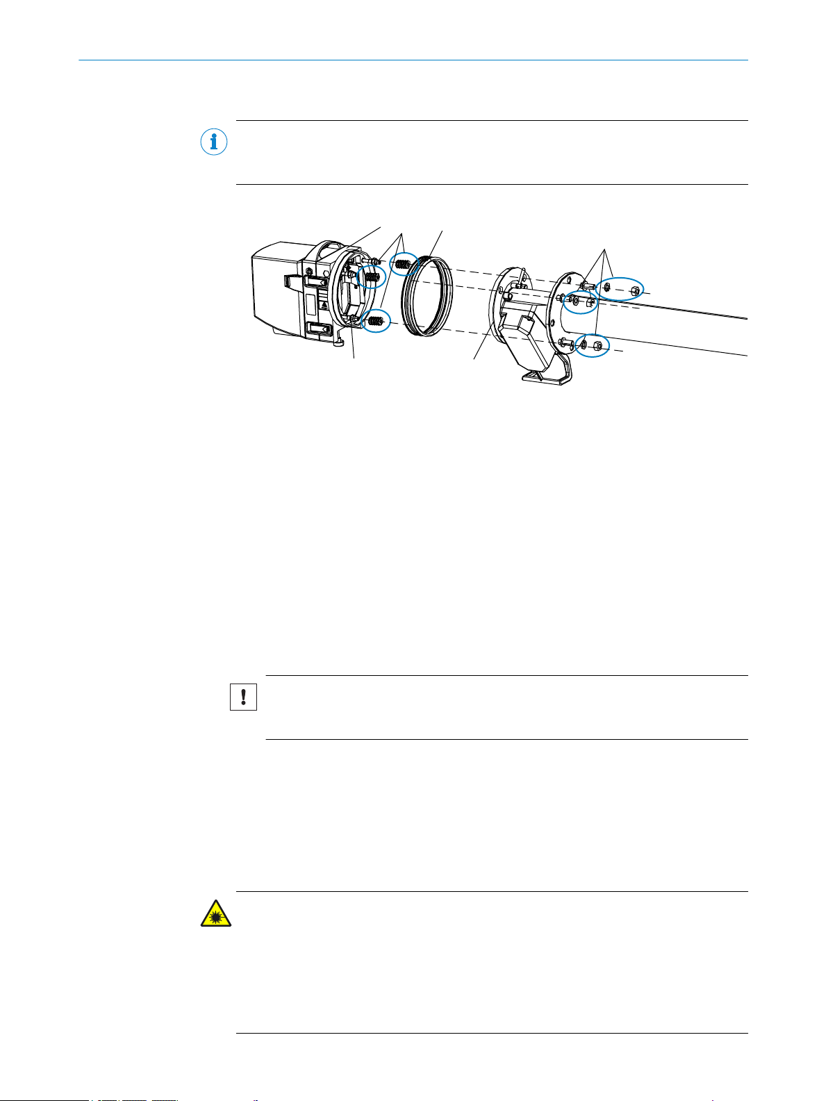
7.5 Fitting the SR-unit on the purge air fixture of the measuring probe
NOTE
The installation procedure is identical for all measuring probe versions. The fixing parts
are supplied with the GM700 measuring system.
Figure 23: Fitting the purge air fixture on the device flange
Intermediate flange of SR-unit (removable)
1
Cup springs, 10 per fastening
2
Rubber sealing ring
3
Threaded pin of flange fixture
4
Device flange
5
Centering disc and nut
6
Fitting the device flange
1. Put 10 cup springs each, back-to-back, onto the three threaded bolts on the inter‐
mediate housing.
2. Pull the sealing ring over the flange of the measuring probe and hang it loosely
over the purge air unit.
3. Push the device flange onto the measuring probe.
4. Position the centering discs.
NOTICE
Observe the direction of the centering disc: The convex side must fit into the
groove on the purge air fixture.
5. Tighten the self-locking nuts with a wrench (19 mm) so that the cup springs are
slightly compressed and an even gap of approx. 4 mm remains.
Fitting the SR-unit on the intermediate housing
see "Fitting the sender/receiver unit on the intermediate housing", page 52.
7.6 Optical fine alignment for device versions for NH3 and HF measurement
CAUTION
Hazard by laser radiation
Device with a laser with protection class 1.
Do not hold any reflecting objects or objects that bundle the laser beam in the
b
laser beam.
During installation or maintenance: Switch the power supply off before opening
b
the device.
8022447/0000/2018-01 | SICK OP E RA T IN G I N ST R UC T IO N S | GM700
Subject to change without notice
43
Page 44

1
3
4
2
5
6
7
8
1.
2.
1
7 COMMISSIONING
WARNING
Eye injuries through laser radiation
The invisible laser beam within the SR-unit is not accessible when fitted. Observe the
following when the SR-unit of the device is swiveled open during installation work for
test purposes and the laser beam is activated:
Never look directly into the laser aperture when opening the SR-unit or the reflec‐
b
tor.
Laser protection class 1: Wear laser protection glasses despite low radiation.
b
Observe national valid limit values and standards that refer to these for industrial
b
safety.
Description of the alignment tool on the SR-unit
Figure 24: Alignment tool on the SR-unit
Visor of the optical alignment
1
LED display for rough view of optical alignment
2
Target of the alignment tool
3
(Alignment on probe version)
4
Alignment on Cross-Duct version
5
Adjusting screw for X alignment; horizontal
6
Adjusting screw for Y alignment; vertical
7
Alignment tool lever
1
Bring the alignment tool into the adjustment position:
1. Turn lever
2. Pull lever down
44
O PE R AT I NG IN S TR U CT I ON S | GM700 8022447/0000/2018-01 | SICK
Subject to change without notice
Page 45

COMMISSIONING 7
On the control unit:
1. Switch to Maintenance mode
a) Press button “maint”.
b) Select “Maintenance mode” and select “On” in selection menu “Mode”.
✓
This activates Maintenance mode
On the sender/receiver unit (XY adjustment with internal alignment tool)
2. First turn and then pull down the lever of the built-in alignment tool to bring the
alignment tool into adjustment position, see Figure above.
3. Look through the visor on the right enclosure side diagonally from above at the
mirror with the target.
NOTE
Light spot color:
HF device version: Red
•
NH3 device version: Green
•
4. Align the position of the light spot. To do this, adjust the nuts for the X and Y align‐
ment on the device flange so that the light spot is positioned in the center of the
target.
NOTE
It takes a few seconds before the light spot moves after adjusting the screws.
✓
Fine alignment is completed when the light spot is positioned in the center of the
target, see Figure “Alignment tool on the SR-unit”.
After successful alignment, push the lever of the alignment tool back to its original
position and secure it with a quarter turn.
7.7 Optical fine alignment on the version for HCI measurement
DANGER
Observe laser warning information, see "Optical fine alignment for device versions for
NH3 and HF measurement", page 43.
NOTE
The wavelength used for HCI measurement is not visible on the target. The power sup‐
ply for the evaluation unit must be switched on.
NOTE
The adjustment, including the warming up time, takes about 2.5 to 5 hours whereby the
actual work is completed in less than 30 minutes
Devices with automatic check cycle perform the first check cycle after the warming up
phase.
On the control unit:
1. Switch to Maintenance mode:
a) Press button “maint”.
b) Select “Maintenance mode” and select “On” in selection menu “Mode”.
c) Select submenu item “Adjust Optical Alignment”.
✓
Maintenance mode/Optical Alignment is active. The EvU display switches to dis‐
play the measuring channel brightness.
8022447/0000/2018-01 | SICK OP E RA T IN G I N ST R UC T IO N S | GM700
Subject to change without notice
45
Page 46

7 COMMISSIONING
On the sender/receiver unit (XY adjustment with internal alignment tool)
1. First turn and then pull down the lever of the built-in alignment tool to bring the
alignment tool into adjustment position, see "Optical fine alignment for device ver‐
sions for NH3 and HF measurement", page 43, Figure “Alignment tool lever”.
2. To do this, adjust the nuts for X and Y alignment on the device flange so that the
measuring channel brightness reaches the maximum value.
✓
After successful alignment, push the lever of the alignment tool back to its original
position and secure it with a quarter turn.
The LED display of the device side serves as additional aid for rough setting.
7.8 Two types of zero point checks
When removed:
SR-unit mounted on the measuring probe and aligned in ambient air corresponding to
the requirements of the zero point conditions. The measuring probe is then fitted again.
Only for devices with GPP measuring probes: When fitted:
Devices with GPP measuring probes can be checked when fitted by feeding suitable
zero gas (nitrogen, clean compressed air in instrument air quality 1). The sequence is
equal to the check with span gas. This function can also be executed in intervals, con‐
trolled by the device. During this procedure, the probe can cool down and swivel, result‐
ing in a zero point error. This effect can be minimized by setting the gas flow to the
required amount and limiting the duration needed for the check. For higher gas temper‐
atures (as from 200°C), the zero gas should be preheated to minimize the swivel effect.
This can be achieved by feeding the zero gas via a heated sample gas line or passively
with a ¼“ metal tube, which is pushed beneath the channel insulation for contact with
the hot duct wall. Here, the preheating spiral that can be ordered from SICK can be
used or a construction adapted for the installation.
The transition from the outlet of the channel insulation to the connection on the zero
gas inlet or the probe has to be insulated, has to reach at least 100°C, but may not
exceed 120 °C on the probe connection.
Figure 25: Preheating spiral, Part No. 2065326
7.8.1 Selecting the ambient temperature range
Select the ambient temperature
On the evaluation unit
1. Select a suitable ambient temperature so that the heater of the SR-unit can stabi‐
lize the optics temperatures.
2. Activate parameter mode.
1)
ISO8573 Class 2 for particle size, content of contamination and oil, H2O dew point
46
O PE R AT I NG IN S TR U CT I ON S | GM700 8022447/0000/2018-01 | SICK
Subject to change without notice
Page 47

3. Select menu Settings, then Ambient Temp.
4. Warning message “DEV TEMP” is output.
5. Select the temperature range according the Table that matches the ambient condi‐
tions at the measuring location, see "Possible ambient temperatures", page 89.
The device automatically determines the appropriate temperature for the optics heater.
Wait approx. 30 minutes for the temperature to change before starting the zero adjust.
7.8.2 Carrying out zero adjust (on the measuring path free from sample gas)
NOTE
As far as supported by the device variant.
Preparation
Ambient temperature range selected.
•
Optical axis alignment completed, see "Optical fine alignment for device versions
•
for NH3 and HF measurement", page 43 and see "Optical fine alignment on the
version for HCI measurement", page 45.
Connect the evaluation unit to the power supply.
•
Warm the measuring system up for approx. 2.5 - 5 hours. The exact warming up
•
time varies according to ambient conditions.
COMMISSIONING 7
Carry out zero adjust
1. Activate Calibration mode: Press button “cal”
2. Select “Zero-Adjust” in submenu item and confirm with “Enter”.
3. The zero adjust starts.
“Zero Measuring” is displayed.
°
When zero adjust has completed, either a positive confirmation or an error
°
message is displayed.
4. Adjustment successful:
w
Switch to Measuring mode or define further parameter settings.
5. Adjustment not possible:
w
The flashing “Malfunction” LED indicates that one or more error messages
are pending.
w
Switch to Diagnosis mode, press button “diag”.
w
Viewing error messages, see "Error messages", page 72.
w
Clear malfunction.
7.8.3 Zero point check with GPP measuring probe
Material required
Gas hoses:
•
Teflon hose (PTFE), type 650 P 0707, 1/4"
°
Steel pipe 1.4571, 1/4"
°
Zero gas: Instrument air, class 2
•
Pressure reducer
•
Supply line 1/4" with cutting-clamping ring connection (Swagelok)
•
Using a gas hose: Inner sleeve (Part No. 5309138)
°
8022447/0000/2018-01 | SICK OP E RA T IN G I N ST R UC T IO N S | GM700
Subject to change without notice
47
Page 48

1 2 3
4
7 COMMISSIONING
Connect zero gas (instrument air) to “Zero gas” gas inlet
Figure 26: Swagelok screw fitting on gas inlet “Zero gas”
Cap nut
1
Clamping rings
2
Inner bushings
3
Gas pipe (open end)
4
1 Connect zero gas (instrument air) to 1st gas inlet “Zero gas”.
w
Take off the cap nut from the gas inlet.
w
Place the cap nut and clamping rings on the open end of the gas pipe.
w
Insert the pipe in the open screw fitting.
w
Tighten the nut with a 9/16" open end wrench.
Connect zero gas (instrument air) to 3rd gas inlet “N2 purging or dyn. zero”.
2 Connect instrument air to the instrument air supply.
w
Connect the pressure reducer to the instrument air supply.
w
Connect the gas hose from the probe to the pressure regulator outlet.
w
Set pressure reducer to 250 kPa.
Carry out the zero point check
On the evaluation unit
1. Switch Maintenance mode off:
w
Mode: Off
w
Press the meas button to start Measuring mode.
✓
The analyzer now starts Measuring mode.
2. Check for error or warning messages, especially on the status LEDs.
3. If error messages are displayed, clear according to the error messages, see "Error
messages", page 72.
4. Set parameters, special times and measuring range, see "Menu tree Parameter",
page 59.
7.9 Repositioning the probe reflector
Reposition the probe when the measuring probe must be realigned in flow direction
(e.g. from vertical to horizontal direction) but the SR-unit must sit vertically.
48
O PE R AT I NG IN S TR U CT I ON S | GM700 8022447/0000/2018-01 | SICK
Subject to change without notice
Page 49

1
2
3
Figure 27: GMP measuring probe flow direction
1
2
3
4
30°
1.
2.
Fitting the probe: Horizontal measuring gap
1
Fitting the probe: Vertical measuring gap
2
Reflector unit on GMP measuring probe
3
COMMISSIONING 7
In accordance with the probe rotation (e.g. at 90°), the reflector in the probe end must
be turned in the opposite direction to this rotation (e.g. –90°) so that the alignment of
the optical beam path to SR-unit is maintained.
1. Loosen the 3 screws on the probe end (screws with nuts remain on the reflector
enclosure).
2. Turn the cover 30° to the right (1.).
3. Pull the reflector unit out (2.).
Figure 28: Reflector on the GMP measuring probe and reflector position marking (Allen screw)
Screws
1
Allen screw to mark the reflector alignment
2
Slotted screw
3
Screw connection for reflector holder
4
1. Loosen and remove the screw connections on the reflector holder.
2. Take both holders and the wedge with the graphite seals out.
3. Take the hollow triple with the triple holder out, position it in the new probe align‐
ment in the appropriate position (e.g. –90°).
4. Swap the Allen and slotted screws: Screw the Allen screw in the triple holder
groove.
8022447/0000/2018-01 | SICK OP E RA T IN G I N ST R UC T IO N S | GM700
Subject to change without notice
49
Page 50

756543
1
2
8 9
ß
4
!
"
1
7 COMMISSIONING
NOTE
The Allen screw shows the position of the hollow triple. It must always point towards the
connector on the SR-unit so that the alignment is correct.
Exchanging
Spring
1
Allen screw to mark the reflector alignment
2
Slotted screw
3
Screw connection for reflector holder
4
Sealing ring
5
Holder (triple-side)
6
Wedge window
7
Graphite sealing ring
8
Holder (flange-side)
9
Allen screw
ß
Allen and slotted screw positions on reflector enclosure swapped
!
Hollow triple repositioned (e.g. –90°)
"
1. Assemble the reflector component in reverse sequence (insert reflector and turn
to the left to the stop; approx. 30°)
2. Fasten the reflector unit to the probe end.
50
Figure 29: Fitting the reflector unit
Allen screw to mark the reflector alignment
1
O PE R AT I NG IN S TR U CT I ON S | GM700 8022447/0000/2018-01 | SICK
Subject to change without notice
Page 51

7.10 Fitting the measuring probe on the flange with tube
Prerequisite
1. Observe all safety information for work on the gas duct, see "Safety information on
commissioning", page 40 and see "Main operating information", page 10.
2. Remove the flange cover and store safely.
3. Provide all materials and auxiliary means at the installation location.
DANGER
Risk of injury when the device drops down
The weight and size make it hard to handle the SR-unit with installed measuring probe.
This increases the risk that the measuring device is damaged when dropped.
Install the SR-unit and the measuring probe singly.
b
Carry out assembly work on parts of the device together with another person when
b
necessary.
Fit the measuring probe with pre-fitted purge air fixture on the flange with tube.
Fit the purge air fixture on the flange with tube with 4 x M16 screws as shown in
b
the Figure.
COMMISSIONING 7
Figure 30: Fitting the measuring probe with pre-fitted purge air fixture on the flange with tube (on
the duct)
M16 screw
1
Washer
2
Flange
3
Flange seal
4
Flange with tube
5
Washer
6
Spring washer
7
Nut
8
NOTE
Fitting the GMP and GPP measuring probes on the flange with tube is identical.
8022447/0000/2018-01 | SICK OP E RA T IN G I N ST R UC T IO N S | GM700
Subject to change without notice
51
Page 52

1
7 COMMISSIONING
7.11 Putting the purge air unit into operation
NOTE
Electrical connections for the purge air unit, see Purge air unit Operating Instructions.
Preparation
Switch the power supply for the purge air unit on for a short time to check the function
and to remove any dust that may have penetrated the purge air hose.
Figure 31: Purge air connection on the purge air fixture of the measuring probe
Purge air hose connection (purge air bracket)
1
On the purge air fixture of the measuring probe:
1. Connect the purge air hose of the purge air unit with a hose clamp to the purge air
bracket connection of the fitting.
2. Switch the purge air supply on.
✓
Purge air supply is now activated and protects the measuring system against cont‐
amination and overheating. Purge air feed must never be switched off when the
SR-unit and reflector are on the sample gas duct.
NOTICE
Attach clearly visible warning information against unintentional switching off on all
switching devices with which the purge air units can be switched off.
7.12 Fitting the sender/receiver unit on the intermediate housing
WARNING
Risk of injury when the device drops down
The weight of the device can cause it to drop down and cause injuries during the work
described in this Chapter.
Carry out assembly work on parts of the device together with another person when
b
necessary.
52
1st step: Separate the sender/receiver unit and the intermediate enclosure
1 Loosen the quick-release fasteners.
2 Pull the hinge pin upwards.
O PE R AT I NG IN S TR U CT I ON S | GM700 8022447/0000/2018-01 | SICK
Subject to change without notice
Page 53

2
1
3
COMMISSIONING 7
2nd step: Fit the sender/receiver unit on the intermediate enclosure
4 Insert the SR-unit in the hinge.
5 Insert the pin from the top downwards through the hinge.
6 Close the quick-release fasteners.
Figure 32: Fitting the GM700 sender/receiver unit on the intermediate housing
Quick-release fasteners of the sender/receiver unit
1
Intermediate housing
2
Hinge pin
3
7.13 Installing the weatherproof cover
Installing the weatherproof cover of the sender/receiver unit:
1 Install the installation plate on the flange of the purge air fixture.
w
Lay the weatherproof cover upside down on the floor.
w
Open and unhinge the locking bolts on both sides.
w
Pull the installation plate upwards and remove it from the cover.
w
Remove the bottom mounting ring.
w
Place the installation plate onto the rubber band of the purge air fixture from
the top.
w
Position the mounting ring on the side of purge air fixture.
w
Screw the bottom mounting ring to the top mounting ring.
8022447/0000/2018-01 | SICK OP E RA T IN G I N ST R UC T IO N S | GM700
Subject to change without notice
53
Page 54

2
2
3
1
1
2
3
4
7 COMMISSIONING
1
1
2
3
Mounting ring
Locking bolts
Installation plate
2
Installation plate
1
Top mounting ring
2
Bottom mounting ring
3
2 Place the weatherproof cover on the installation plate.
w
Position the cover on the installation plate from the top.
w
Engage the locking bolts and close again.
7.14 Starting measuring operation
NOTE
The device is delivered from the factory with the parameter settings specified by the
customer when ordering. When these parameter specifications match the parameters
during commissioning, measuring operation can be started after fine optical alignment
by pressing the “meas” button. The device can be configured to meet the plant condi‐
tions when required.
Start Operating mode:
1 Switch Maintenance mode off, menu path: see "Menu tree Maintenance",
page 61.
2 Set Mode to“Off”.
3 Press “meas”.
54
O PE R AT I NG IN S TR U CT I ON S | GM700 8022447/0000/2018-01 | SICK
Subject to change without notice
Page 55

Checking status LEDs, error and warning messages
NOTE
Quick check of Measuring screens on the LC display of the evaluation unit:
b
When error or warning messages are present:
b
b
7.14.1 Operating states
Message on EvU display Meaning
INIT Initializing the evaluation unit
INITIALISATION
SIGNAL_ADJUST Adjusting amplification to changed transmission
MEASURING
MEASURING LL
MEASURING LD Measuring operation; Beam length tracked (line locking
MAINTENANCE Maintenance mode (no measurement)
DOWNLOAD
COMMISSIONING 7
Using the Operating Instructions, see "Operating and display elements (evaluation
unit)", page 56.
Determine and clear the error cause using the Operating Instructions, see "Serial
interface commands - Diag", page 62, and the Error and Warning Message
Tables, see "Error messages", page 72 and see "Warning messages", page 74.
If the error cause cannot be cleared:
Contact SICK Service.
Initializing the SR-unit
Measuring operation
Measuring operation with active tracking of the laser
beam length (line locking)
done)
Download new software (for Service purposes only)
7.14.2 Select the ambient temperature range
NOTICE
Temperature stabilization: 30 minutes
The device stabilizes the temperature after the temperature is modified.
Warning message “DEV TEMP” is output during temperature stabilization.
•
1 Activate Parameter mode.
2 Menu path: Setting -> Ambient Temp.
3 Select the temperature range from the Table that matches the ambient conditions
best at the measuring location, see "Possible ambient temperatures", page 89.
8022447/0000/2018-01 | SICK OP E RA T IN G I N ST R UC T IO N S | GM700
Subject to change without notice
55
Page 56

maintcalpardiag
GM 700
Evaluation Unit
CO
CO
2
H2O
mg/
m
3
236
Ref. conditions
Hum: wet
Measuring
Operation
Service
Warnin
Malfunction
GM700
Evaluation Unit
NH3
mg/
m
3
236
Operation
Service
Warning
Malfunction
GM 700
Evaluation Unit
NH3
mg/
m
3
236
Ref. conditions
Hum: wet
Enter meas
diag par cal maint
Measuring
Operation
Service
Warning
Malfunction
GM 35
Evaluation Unit
CO
CO
2
H2O
mg/
m
3
236
Ref. conditions
Hum: wet
Enter meas
diag par cal maint
Measuring
Measuring
Enter meas
maintcalpardiag
Operation
Service
Warning
Malfunction
Ref. conditions
Hum: wet
1 2
65
43
8 OPERATION
8 Operation
8.1 Safety
WARNING
Hazard for persons and plant through unsafe operation of the measuring system
If the device is or could be in an unsafe state:
Put the device out of operation.
b
Disconnect the device from the main supply voltage and signal voltage.
b
Secure the device against unallowed or unintentional start-up.
b
NOTE
More information concerning the detection of unsafe operating states, see Chapter
“Visual check”.
8.1.1 Check before start-up
Before every start-up
Check all enclosures are closed
b
– Enclosure cover
– Cable inlets
– Enclosure openings
8.2 Operating and display elements (evaluation unit)
Figure 33: GM700 operator panel
GM700 evaluation unit, cast metal enclosure
1
GM700 evaluation unit, sheet steel enclosure
2
Display for
3
•
All current measured values
•
Computed value
•
Menu navigation
Status LEDs to signal operating and malfunction states
4
Function buttons for menu navigation and input
5
6
Function buttons for menu selection
56
O PE R AT I NG IN S TR U CT I ON S | GM700 8022447/0000/2018-01 | SICK
Subject to change without notice
Page 57

LEDs
Table 11: Significance of LEDs
LED Significance / possible cause
Measuring mode
•
The device is switched on, power voltage is available
•
OPERATION
Service mode
•
SERVICE
Warning message
•
At least one warning message pending
•
Reading warning messages, see Diagnosis mode (diag)
Warning
MALFUNCTION
•
Device malfunction
•
At least one malfunction message pending
•
Reading malfunction messages, see Diagnosis mode (diag)
•
OPERATION 8
8022447/0000/2018-01 | SICK OP E RA T IN G I N ST R UC T IO N S | GM700
Subject to change without notice
57
Page 58

meas
8 OPERATION
8.3 Menu tree of the evaluation unit
NOTE
Menu texts are shown in English.
8.3.1 Menu tree Measuring
Menu level Explanation
Measuring
8.3.2 Menu tree Diagnosis
Current measured values depending on
•
device version
Reference variables (wet, dry)
•
Menu level
Diagnosis Diagnosis
Malfunction Current error messages (plain text)
Warning Current warning messages (plain text)
Sensor values Displays diagnostic values and control values
GM700 Sensor values
GM700
Cross-Duct: OH
Cross Duct: Reflector
Current monitored sensor values (amplification
setting, internal temperature control, control val‐
ues, etc.)
58
O PE R AT I NG IN S TR U CT I ON S | GM700 8022447/0000/2018-01 | SICK
Subject to change without notice
Page 59

OPERATION 8
8.3.3 Menu tree Parameter
Menu level Explanation
Parameters Parameter
Settings Parameter settings/display of system compo‐
nents
Physical Unit
Component
Average Avg. Time 0 ... 300 s
Meas. Distance Active 200 ... 8000 mm
Gas temperature
Pressure
Humidity Subst. Subst.: 0 ... 93.0 %Vol
Unit mg/m3, ppm
t: actual, 25 °C, 20 °C, 0 °C
•
Ref. condition
p: actual, 1013 mbar
•
Hum.: wet, dry
•
Source Probe, Subst. Analog In
Subst. –100 ... 2000 °C
Unit °C, °F, K
Source Probe, Subst. Analog In
Subst. 600 ... 15000 hPa
Live Zero 0, 4 mA
Component: e.g., NH3, - -, p, T
Analog Out
Output 1
Output 2
Output 3
Range low: 0 ... 999999
Range high: 0 ... 999999
Cycle Out: No, Yes
Component: e.g., NH3,, - -, p, T
Range low: 0 ... 999999
Range high: 0 ... 999999
Cycle Out: No, Yes
Component: e.g., NH3,, - -, p, T
Range low: 0 ... 999999
Range high: 0 ... 999999
Cycle Out: No, Yes
8022447/0000/2018-01 | SICK OP E RA T IN G I N ST R UC T IO N S | GM700
Subject to change without notice
59
Page 60

8 OPERATION
Menu level Explanation
Unit: °C, K, °F
Input 1 T
Analog In
Input 2 p
Regress Funct. Span 0.50 ... 1.99
Zero ±999
Ambient Temp. Range
t (Feed Test Gas) Period d (days), only when purge cell is included
Check cycle Period 0 ... 24 h
Enable Yes, No
Live Zero: 0, 2, 4 mA
Range low: 0 ... 15000
Range high: 0 ... 15000
Unit: hPa
Range low: 0 ... 15000
Range high: 0 ... 15000
0 ... 50 °C
•
–10 ... 40 °C
•
–20 ... 30 °C
•
–30 ... 20 °C
•
–40 ... 10 °C
•
Repet. 0 ... 24 h (only GPP)
t (purge) 0 ... 900 s; purge time until the process gas con‐
Zero Adjust
centration is zero
t (delay) 0 ... 1800 s; delay until gas enters again
Delta T 0 ... 999 °C; temperature difference at which a
zero adjust is carried out
Device Serial Number Head _ _ _ _ _ _ _ _
Laser _ _ _ _ _ _ _ _
EvU _ _ _ _ _ _ _ _
Software Revision
■
GMM700-X
■
XXXXXXX XXXX
■
GMM700/DSP
■
XXXXXXX XXXX
60
O PE R AT I NG IN S TR U CT I ON S | GM700 8022447/0000/2018-01 | SICK
Subject to change without notice
Page 61

8.3.4 Menu tree Calibration
Menu level Explanation
Calibration Calibration
Check cycle Start CCY (Check Cycle) Check cycle for test purposes, e.g., after mainte‐
nance
Zero Adjust Start ZeroAdjust
Zero point determination, e.g., during commis‐
sioning or maintenance tasks based on the zero
path
Zero Adj. Stack Start ZeroAdjust Only GPP probe: Zero point determination with
Password
(1234)
measuring device on gas duct
Zero gas must be connected to the GPP probe.
Box measuring Start Meas. Check of measuring components with span gas
via a filter box
OPERATION 8
8.3.5 Menu tree Maintenance
Menu level Explanation
Maintenance
Maint. Mode Mode: Off, On Maintenance operation: On, Off
Adj. Opt. Align. Opt. Alignment Displays optical alignment of SR-unit
AO 1: 4 mA
Test Analog Out
Tests the analog outputsAO 2: 4 mA
AO 3: 12.5 mA
Test Analog In
AI 1: 0 mA
Tests the analog inputs
AI 2: 0 mA
AI 3: 0 mA
Relay 1: On (Off)
Test Relay
Tests the relay outputsRelay 2: On (Off)
Relay 3 Off (On)
DI 1: Open
Test Digital In
Tests the digital inputsDI 2: Open
DI 3: Open
Push Diag
RS232 Outputs the complete parameter set via the
RS232 Service interface
Reset System Restarts the measuring system
Reset Parameter
Resets parameters to factory settings
a All settings are overwritten!
8022447/0000/2018-01 | SICK OP E RA T IN G I N ST R UC T IO N S | GM700
Subject to change without notice
61
Page 62

8 OPERATION
8.4 Operating using the serial interface
NOTE
Menu texts are shown in English.
8.4.1 Significance of command line elements
Table 12: Significance of command line elements
Element Meaning Text style used
SAMPLE Shows the name of the command or utility pro‐
gram.
{variable} Shows several options from which the user
must select one, more or all.
[option] Shows optional elements. Small letters in [square brack‐
. , : ; Punctuation marks are part of the command
and to be inserted as such.
<cr> Stands for pressing Enter (on the computer
keyboard).
CAPITAL LETTERS
Small letters in {round brack‐
ets}
ets]
Small letters
Small letters
8.4.2 Setting for serial interfaces
Table 13: Standard setting for serial interface
Parameter Description / value
Baud rate 9600 Baud
Data bits 7
Parity Even parity
Stop bits 1
Protocol No protocol
Interface line 1:1
Connection 2-2 / 3-3 / 5-5
8.4.3 Serial interface commands - Meas
Table 14: Serial interface command for measuring
Serial interface command Description
GM700<<GOTO MEAS meas / measuring operation
8.4.3.1 Serial interface command - MEAS
Start measuring operation/switch to measuring operation
Syntax:
GM700<<GOTO MEAS
8.4.4 Serial interface commands - Diag
8.4.4.1 Table with warning messages
Call up the Table of warning messages.
Syntax:
GM700<<DIS WTBL
62
O PE R AT I NG IN S TR U CT I ON S | GM700 8022447/0000/2018-01 | SICK
Subject to change without notice
Page 63

8.4.4.2 Error messages Table
Call up the Table with error messages
Syntax:
GM700<<DIS MTBL
8.4.4.3 View the device configuration
Call up the list of the device configuration
Syntax:
GM700<<DIS CONFIG
8.4.4.4 Check the system state and configuration
Output of the current system state and configuration
Syntax:
DIS DEV PARA
8.4.4.5 Call up diagnostic data
OPERATION 8
Command “DIS MERB” calls up the diagnostic data.
Syntax:
GM700<<DIS MERB
8022447/0000/2018-01 | SICK OP E RA T IN G I N ST R UC T IO N S | GM700
Subject to change without notice
63
Page 64

9 MAINTENANCE
9 Maintenance
9.1 Safety
CAUTION
Risk of device damage when the optics purge air is switched off too soon
Hot and contaminated gas can cause device damage when the optics purge air is
switched off when the SR-unit and the measuring probe are still in the gas duct.
b
WARNING
Endangerment of electrical safety during installation and maintenance work when the
power supply is not switched off
b
b
b
b
Switch off the purge air unit only after removal of the SR-unit from the gas duct.
Before starting the work on the device, ensure the power supply can be switched
off using a power disconnector switch/circuit breaker in accordance with DIN EN
61010-1:2010.
Make sure the power disconnector switch is easily accessible.
An additional disconnecting device is mandatory when the power disconnector
switch cannot be accessed or only with difficulty after installation of the device
connection.
After completion of the work or for test purposes, the power supply may only be
activated again by authorized personnel complying with the safety regulations.
DANGER
Risk of injury by electrical accident
■
If the device has to be opened for setting or service work:
w
First disconnect the device from all voltage sources.
■
If the opened device must remain under voltage during work:
w
Have the work done by skilled persons familiar with potential risks. If it is nec‐
essary to remove or open internal components, live parts could be exposed.
■
If any liquid has penetrated electrical device components:
w
Put the device out of operation and interrupt the power voltage at an external
point (e.g. disconnect the power cable). Then contact service technicians of
the manufacturer or correspondingly trained skilled persons to have the
device repaired.
■
If safe operation of the device is no longer possible:
w
Put the device out of operation and secure against unauthorized start-up.
■
Do not interrupt the protective conductor connections inside or outside the device.
WARNING
Health risk through contact with toxic gases
The modules and devices contain enclosed, potentially dangerous gases that can
escape should a defect or leak occur. If a leak occurs, the concentrations inside the
enclosed device can increase up to 25 ppm.
■
NH3: 17 ml max. total amount
■
HF: 6 ml max. total amount
64
Check the state of the seals on the device/module regularly.
b
Only open the device when good ventilation is available, especially when a leak of
b
one of the device components is suspected.
O PE R AT I NG IN S TR U CT I ON S | GM700 8022447/0000/2018-01 | SICK
Subject to change without notice
Page 65

WARNING
Risk of chemical burns/poisoning through caustic/toxic residues on components with
sample gas contact
After the device has been decommissioned or removed from the measuring channel,
process gas residues can exist as deposits on components with sample gas contact
(e.g., gas filter, gas-carrying lines etc.). These residues can be odorless or invisible
depending on the gas mixture in the duct. Without protective clothing, contact with such
contaminated components can lead to severe burns or poisoning.
Take appropriate protective measures for work (e.g., by wearing a safety mask, pro‐
b
tective gloves and acid resistant clothes).
In case of contact with skin or the eyes, rinse immediately with clear water and
b
consult a doctor.
Decontaminate all contaminated components according to regulations after disas‐
b
sembly.
9.2 Maintenance plan
Table 15: Maintenance intervals
Inter‐
1
val
1W
1M
1Y
1
1W = Weekly, 1M = Monthly, 3M = Every 3 months, 6M = Every 6 months, Y = Yearly
MAINTENANCE 9
Maintenance work Reference
Check that measured values in the control area
are plausible
Visual inspection of system
Clean window
Check optical alignment
Check ambient temperature range
Check and/or clean the purge air unit
Check analyzer with span gas Normally carried out by SICK Service.
Control and track the laser working point during
measurement
see "Call up diagnostic data", page 63.
see "Visual check", page 67.
see "Cleaning the optical interfaces",
page 67.
see "Optical fine alignment for device versions
for NH3 and HF measurement", page 43, see
"Optical fine alignment on the version for HCI
measurement", page 45.
see "Ambient temperature ranges with test cell"
and see "Ambient temperature ranges (closed
cell)", page 89.
see "Cleaning the purge air unit", page 69
and purge air unit Operating Instructions.
Normally carried out by SICK Service.
9.2.1 Maintenance protocol
The following data should be recorded:
Maintenance dates
•
Work done
•
Special observations
•
Required consumables and spare parts
•
9.2.2 Expendable, wearing and spare parts
Recommendation for two years operation
Table 16: Expendable and spare parts for two years operation
Part Part number
GM700 sender/receiver unit
8022447/0000/2018-01 | SICK OP E RA T IN G I N ST R UC T IO N S | GM700
Subject to change without notice
65
Page 66

2
1
3
9 MAINTENANCE
Part Part number
Spare parts set, mounting kit, flange (2 pcs.) 2039628
GPP measuring probe
Sealing tape for flange, Neoprene/Teflon for GPP 2064871
Spare parts set, seal GPP700 (2 pcs.) 2032919
Seal between probe and flange (2 pcs.) 4032310
Spare parts set, GPP700 reflector, enclosed 2092801
GMP measuring probe
Triple, gold-coated 2076492
Sealing ring, GMP and SLV (2 pcs.) 2083220
Seal between probe and flange 4032310
Diverse
Filter element, micro, top element for SLV unit (4 pcs.) 5306091
Optics cloths (2 pcs.) 4003353
9.3 Preparatory work
NOTE
Some maintenance tasks will cause the measuring device to switch to malfunction
Activate Maintenance mode before starting the work.
b
NOTE
Ensure good accessibility to the device in accordance with valid accident preven‐
b
tion regulations.
Provide suitable work platforms/pedestals.
b
NOTE
A zero path must be available for zero adjust.
9.4 Removing the SR-unit from the intermediate housing
66
Figure 34: Opening the GM700 Ex sender/receiver unit and removing the intermediate housing
Quick-release fasteners of the sender/receiver unit
1
Intermediate housing
2
Hinge pin
3
O PE R AT I NG IN S TR U CT I ON S | GM700 8022447/0000/2018-01 | SICK
Subject to change without notice
Page 67

9.5 Visual check
MAINTENANCE 9
1 Switch device off.
2 Open the SR-unit enclosure by releasing the quick-release fasteners.
3 Immediately attach the cover on the device flange opening.
Removing the intermediate housing
1 Hold the unit tight.
2 Pull out the hinge pin.
3 Remove the sender/receiver unit.
All device components
Check SR-unit housing for mechanical damage.
b
Clean the respective enclosures (all components) if contaminated.
b
Check all cables for damage. Pay attention to chafe marks and kinks on cable
b
ducts.
Check all hose fittings for tight seat.
b
Check all electrical connections are free from corrosion and have a tight seat.
b
Check grounding conductors are free from corrosion.
b
Check flange and screw fittings for tight seat.
b
Evaluation unit
Visual check of surfaces:
•
– Enclosure and fastening
– Opening and closing the front door
– Clean the inspection window
– Check for moisture outside and inside the enclosure
Electrical check:
•
– LED
– Tight seat of line connections
Damage on the evaluation unit (e.g., LC display failure):
w
Contact SICK Service.
9.6 Cleaning the optical interfaces
WARNING
Risk of injury through uncontrolled escape of process gas when the gas duct is
opened when under overpressure
Swiveling the SR-unit open can lead to contact with toxic and/or hot gases with over‐
pressure in the duct.
All persons at the gas duct during opening of the device must follow the protective
b
measures mandatory in operation. Pay special attention to protective masks and
protective gloves.
Prepare a suitable cover for the opening on the device flange of the SR-unit and
b
keep it available.
Immediately place the cover on the opening of the device flange once the SR-unit
b
has been opened.
8022447/0000/2018-01 | SICK OP E RA T IN G I N ST R UC T IO N S | GM700
Subject to change without notice
67
Page 68

1
MAINTENANCE
9
DANGER
Important information for safe handling of the GM700 SR-unit on the device version
with HF measurement
For device software versions before 9105060_YEK0, a higher laser radiation might
occur.
Laser class 1 of the IEC 60825-1:2014-5: Only use device software
b
9105060_YEK0 or a newer software version.
Never look directly into the laser aperture when opening the SR-unit.
b
Always wear laser goggles or switch the device off during maintenance work.
b
Observe valid national limit values and respective standards for work safety.
b
NOTICE
Deviations of EN60825-1:2014-08 “Laser safety” from the Directive 2006/25/EC
The Directive has been adapted to cover changes in the health and safety regulation for
artificial optical radiation. Deviations occurred through changes in EN60825-1:2014-08
“Laser safety” from Directive 2006/25/EC.
Always observe the user information in the Annex of these Operating Instructions!
b
Table 17: 1
Material required Part number
Optics cloths (2 pcs.) 4003353
Demineralized water
1 Switch the device off and swivel the SR-unit away from the intermediate enclosure.
2 Flap the target upwards and check the SR-unit window underneath for contamina‐
tion.
Figure 35: Flap the target holder upwards
Target holder
1
3 When necessary: Clean the window with an optics cloth and demineralized water.
NOTICE
Do not use cleaning agents. Residues can falsify measuring results.
68
4 Close the enclosure immediately after cleaning to protect the cleaned optical inter‐
faces against moisture and dust.
O PE R AT I NG IN S TR U CT I ON S | GM700 8022447/0000/2018-01 | SICK
Subject to change without notice
Page 69

9.7 Cleaning the purge air unit
Table 18: 1
Materials required Part number
Filter element, micro, top element for SLV unit (4 pcs.) 5306091
CAUTION
Contaminated purge air supply can damage the measuring system
Inadequate cleaning of the purge air supply can cause blocking of tubes or filters. The
measuring system can no longer be protected from contaminated sample gas.
Regularly check and clean the purge air supply.
b
NOTE
Further information on maintenance and cleaning can be found in the Data Sheet of
the purge air unit.
NOTE
The filter of the purge air unit must be replaced at the latest when the low-pressure
sensor on the filter outlet triggers.
MAINTENANCE 9
Preparation
For prolonged maintenance work on the purge air supply: Remove SR-unit and
•
reflector unit from the gas duct
For short maintenance work on the purge air supply: Swivel SR-unit and reflector
•
unit from the gas duct
Cleaning the purge air unit
1. Put the purge air unit out of operation and completely remove the purge air hoses.
2. Replace the air filter in the purge air unit and clean the inside of the purge air unit.
3. Completely swivel open the SR-unit and the reflector so that dust that was possibly
blown through the purge air hose is not deposited on the windows.
4. Put the purge air unit back into operation.
8022447/0000/2018-01 | SICK OP E RA T IN G I N ST R UC T IO N S | GM700
Subject to change without notice
69
Page 70

10 TROUBLESHOOTING
10 Troubleshooting
10.1 Safety
CAUTION
Device damage through short circuit on the device
The internal electronics can be damaged when signal connections are established and
the power supply is switched on. This is also valid for plug connections.
Disconnect the GM32 Ex and any connected devices from the voltage supply.
b
WARNING
Risk of chemical burns/poisoning through caustic/toxic residues on components with
sample gas contact
After the device has been decommissioned or removed from the measuring channel,
process gas residues can exist as deposits on components with sample gas contact
(e.g., gas filter, gas-carrying lines etc.). These residues can be odorless or invisible
depending on the gas mixture in the duct. Without protective clothing, contact with such
contaminated components can lead to severe burns or poisoning.
Take appropriate protective measures for work (e.g., by wearing a safety mask, pro‐
b
tective gloves and acid resistant clothes).
In case of contact with skin or the eyes, rinse immediately with clear water and
b
consult a doctor.
Decontaminate all contaminated components according to regulations after disas‐
b
sembly.
Electrical safety
DANGER
Electrical accident through bare, live lines
When uninstalling, unsecured, live lines can lead to serious accidents.
Switch the power supply to the device off before starting uninstallation.
b
If power supply is required during uninstallation: Secure all live lines during unin‐
b
stallation work so that nobody can be injured.
DANGER
Hazard by voltage
Lines in the subassemblies of the measuring system are live and can cause serious
injuries through electric shock when touched.
Disconnect the subassemblies or lines involved from the power supply during
b
installation, maintenance and repair work.
10.2 Monitoring and diagnostic system
The device has an integrated system that continually checks the operating state of the
SR-unit and the evaluation unit. Corresponding messages are displayed for deviations
from the normal state and recorded in the devices for later evaluation. Messages for
the two system components are categorized into error messages and warning mes‐
sages depending on the anticipated effects:
70
O PE R AT I NG IN S TR U CT I ON S | GM700 8022447/0000/2018-01 | SICK
Subject to change without notice
Page 71

TROUBLESHOOTING 10
Significance of warning messages
Measuring results are not (yet) directly influenced by a deviating system state.
•
Observance and clearance of the cause(s), e.g., through maintenance measures,
•
are necessary to prevent subsequent errors or device damage
Significance of malfunction messages
Measuring operation is no longer possible or no longer reliable.
•
NOTE
Warning and error messages are stored in the built-in message memory of the evalua‐
tion unit.
10.3 Device not functioning
Table 19: Device not functioning
Possible cause Measure
Power supply not connected. Check power cable and connections.
Main power supply failure. Check power supply (e.g. socket, external disconnecting device).
Internal operating temperatures are
incorrect.
Internal software not functioning. Can only occur with complex internal malfunctions or after strong external influences
Check whether error messages exist.
(e.g., strong electromagnetic interfering pulse).
Switch device off and then back on again after a few seconds.
10.4 Evaluation unit not functioning
Table 20: Device not functioning
Error indication Possible cause Measure
Malfunction LED blinks,
(Warning LED possibly
on)
Evaluation unit not
responding
Plain-text error messages indicate possible
causes.
Operating voltage not set correctly.
Power supply on evaluation unit incorrect. 1 Provide power supply from plant.
Defective fuse.
Cause cannot be determined. 1 Disconnect all system components from
Error occurs again.
24V/5V supply defective. 1 Check 24V/5V supply.
1 Trigger Diagnostic mode by pressing the
2 Call menu Malfunction (and/or Warning).
3 Check and clear the specified malfunction.
1 Check operating voltage set.
2 If necessary, replace fuse.
2 Check/reconnect connections on the sys‐
1 Check fuses in the evaluation unit.
2 Exchange when necessary.
2 Check the CAN bus cable from the evalua‐
b
2 Exchange evaluation unit and/or electron‐
3 Contact Service.
“diag” button.
tem components
the power supply and reconnect one at a
time.
tion unit to the SR-unit resp. terminal box.
Replace the last component connected,
contact Service.
ics board module.
8022447/0000/2018-01 | SICK OP E RA T IN G I N ST R UC T IO N S | GM700
Subject to change without notice
71
Page 72

10 TROUBLESHOOTING
Error indication Possible cause Measure
Display output: Corrupt
Parameters: Reset
Memory
10.4.1 Communication fault between evaluation unit and receiver
Inconsistent data detected in parameter memory 1 Press Enter.
2 If necessary, reconfigure the parameters.
3 Exchange the evaluation unit.
4 Contact SICK Service.
Error message: "Sensor Communication"
The receiver sends data continually to the evaluation unit, an error message is gener‐
ated automatically when no data is received there.
Check following connections:
1 Evaluation unit -> receiver.
2 Cable connection on the plug-in terminal in the evaluation unit.
3 Cable to receiver.
4 Outer plug-in connector on receiver.
5 Inner plug-in connector in receiver.
A system restart is carried out. This resets
the parameters to the factory settings.
If the error message appears again:
10.5
Error messages
10.5.1 Error messages
Table 21: Error Table: Malfunction messages
Error message Description Possible cause / clearance
System
DSP: BOOT ERROR
DSP…Digital Signal
Processor
DSP: INV PARA Incompatible software (SR-unit)
DSP: NO RESP Electronics communication problem (SR-unit).
EEPROM: CONTROL Invalid microcontroller parameters (SR-unit).
EEPROM: LASER Invalid laser parameters.
FIT: DIV BY 0 Error during signal evaluation:
FIT: NO CONV Error during signal evaluation:
Error during start process
Invalid values entered.
Incorrect parameter values.
•
Hardware defect.
•
Incorrect parameter values.
•
Hardware defect.
•
Restart device.
b
– Press maint button to activate mainte‐
nance.
– Trigger menu Reset System or
– switch device off and on again.
If not successful, contact Service.
b
Check software version, contact Service if neces‐
b
sary.
Correct erroneous values.
b
Restart device; see above.
b
If not successful, contact Service.
b
Restart device; see above.
b
If not successful, contact Service.
b
Restart device; see above.
b
If not successful, contact Service.
b
Check measuring distance, substitute for tem‐
b
perature and pressure parameters, correct when
necessary.
Restart device; see above.
b
If not successful, contact Service.
b
Check measuring distance, substitute for tem‐
b
perature and pressure parameters.
Increase Average parameter
b
a Attention, these parameters may only be mod‐
ified by trained personnel.
Restart device; see above.
b
If not successful, contact Service.
b
72
O PE R AT I NG IN S TR U CT I ON S | GM700 8022447/0000/2018-01 | SICK
Subject to change without notice
Page 73

TROUBLESHOOTING 10
Error message Description Possible cause / clearance
FIT: S MATRIX Error during signal evaluation:
Incorrect parameter values.
•
Hardware defect.
•
Incompatible device Incompatible software (SR-unit).
INIT: NO LINE Incompatible software (SR-unit).
LD: PELT ERROR
LD…laser diode
LD: TEMP ERROR Laser wavelength adjustment outside allowed range.
MEAS: M PLAUS Measuring results from measuring channel not plausi‐
MEAS: R PLAUS Measuring results from measuring channel not plausi‐
MEAS: REF CONC (only for
device with closed cell)
Sensor communication SR-unit not connected correctly.
SIG: DARK VALUE Dark values of receiver element too high:
SIG: K HIGH Monitoring channel signal too high.
SIG: K LOW Monitoring channel signal too low.
SIG: M HIGH Measuring channel signal too high.
SIG: M LOW Measuring channel signal too low:
SIG: R HIGH Reference channel signal too high.
SIG: R LOW Reference channel signal too low.
Zero gas measurement for
NH
3
Z MEAS: RANGE Unallowed results during zero gas measurement:
Sensor Communica‐
tion???
Temperature measurement on Peltier element defec‐
tive:
Possible hardware defect.
b
Absorption line “lost”.
b
Laser diode defective.
b
ble:
Incorrect parameter values.
b
Strong signal interference.
b
Hardware defect.
b
ble:
Incorrect parameter values.
b
Strong signal interference.
b
Hardware defect.
b
Gas concentration in reference cell too low.
Possible hardware defect.
b
Optical interfaces (front window) of SR-unit or
b
reflector contaminated.
Optical axes alignment too inaccurate.
b
Hardware defect.
b
Zero gas missing.
b
Optical interfaces (front window) of SR-unit or
b
reflector contaminated.
Optical axes alignment too inaccurate.
b
Communication fault between evaluation unit and
GM700 SR-unit
Check measuring distance, substitute for tem‐
b
perature and pressure parameters, correct when
necessary.
Restart device; see above.
b
If not successful, contact Service.
b
Check software version.
b
Contact Service.
b
Restart device; see above.
b
If not successful, contact Service.
b
Restart device; see above.
b
If not successful, contact Service.
b
Restart device; see above.
b
If not successful, contact Service.
b
Check measuring distance, substitute for tem‐
b
perature and pressure parameters.
Increase Average parameter.
b
a Attention, these parameters may only be mod‐
ified by trained personnel.
Restart device; see above.
b
If not successful, contact Service.
b
Restart device; see above.
b
If not successful, contact Service.
b
Exchange reference cell.
b
Contact Service.
b
Check CAN connection and repair if necessary.
b
Contact Service.
b
Contact Service.
b
Contact Service.
b
Contact Service.
b
Clean front window, chapter 9.6.
b
Check optical alignment and correct if necessary,
b
chapter 7.6 and see "Optical fine alignment on
the version for HCI measurement", page 45.
If not successful, contact Service.
b
Contact Service.
b
Contact Service.
b
Check zero gas supply and repair if necessary.
b
Clean front window, chapter 9.6.
b
Check optical alignment and correct if necessary,
b
chapter 7.6 and see "Optical fine alignment on
the version for HCI measurement", page 45.
Check connections:
Evaluation unit - SR-unit.
b
Lines to SR-unit.
b
Outer plug-in connectors on SR-unit.
b
Inner plug-in connectors in SR-unit.
b
8022447/0000/2018-01 | SICK OP E RA T IN G I N ST R UC T IO N S | GM700
Subject to change without notice
73
Page 74

10 TROUBLESHOOTING
NOTE
This Table also contains recommended solutions that can only be performed by specially trained personnel.
10.5.2 Warning messages
Table 22: Warning messages
Warning message Description Possible cause / clearance
Feed Test Gas No detectable sample gas concentration (see Interval).
FIT: LINEPOS Deviation of absorption line position:
Line during start process not aligned properly.
b
MEAS: REF CONC (only for
device with closed cell)
DEV: TEMP Optic of SR-unit out of allowed temperature range:
Gas concentration in reference cell too low; measure‐
ment still possible.
Warm-up phase after switching on.
b
Ambient temperature too high.
b
Feed span gas. (GMK)
b
Wait until the warning message disappears after
b
a few minutes.
Restart device
b
– Activate Maintenance mode with maint
button.
– Trigger menu item Reset System or
– switch device off and on again.
If not successful, contact Service.
b
Plan and prepare reference cell replacement.
b
Wait until the temperature has stabilized.
b
Select different ambient temperature range.
b
Cool device.
b
10.6 Repairing inadequate purge air supply
CAUTION
A faulty purge air supply can damage the measuring system
The measuring system can no longer be protected from contaminated sample gas and
is damaged.
When the purge air supply appears faulty, immediately perform all actions
b
described in these Operating Instructions.
Indications of insufficient purge air supply
Unusual noises from the area of the purge air supply
•
On systems with pressure difference sensor: An appropriate error message occurs
•
Rise in enclosure temperature
•
Unusually rapid contamination of the window of the measuring device
•
Information for fast correction of faults
Air filter of purge air unit clogged?
•
Purge air hose slipped off or broken?
•
Power supply of the purge air unit failed?
•
Check the purge air unit
Pull the purge air hose on the SR-unit: A strong air flow must be noticeable.
b
Reinstall the purge air hose immediately.
b
74
Measures for insufficient purge air supply
If the purge air unit is not immediately functional:
•
w
Remove SR-unit and measuring probe from the gas duct.
For a short malfunction:
•
w
Swiveling the SR-unit out is sufficient
O PE R AT I NG IN S TR U CT I ON S | GM700 8022447/0000/2018-01 | SICK
Subject to change without notice
Page 75

Bring the purge air unit back to correct operation immediately.
•
Replace provisionally with a different purge air supply with at least the same purge
•
air throughput.
10.7 Corrosion on flange
Table 23: Corrosion on flange
Possible errors Possible causes Action
Corrosion on flange.
Unsuitable materials
TROUBLESHOOTING 10
Check project planning.
b
8022447/0000/2018-01 | SICK OP E RA T IN G I N ST R UC T IO N S | GM700
Subject to change without notice
75
Page 76

11 DECOMMISSIONING
11 Decommissioning
11.1 Safety information for decommissioning
Technical knowledge needed / requirements for decommissioning
NOTICE
You are basically familiar with the device.
•
You are familiar with conditions at the installation location, especially possible haz‐
•
ards through the gases in the gas duct (hot/dangerous to health).
You are capable of recognizing and preventing danger by possibly escaping gases.
•
If one of these requirements is not met:
Contact SICK Customer Service or your local SICK representative.
b
Gas
DANGER
Hazard by gas escaping when the SR-unit is swiveled out
Overpressure in the gas duct can cause hot and/or noxious gases to escape when the
SR-unit is swiveled out.
Swivel the SR-unit out only when you have taken suitable safety measures.
b
Set the lever on the purge air fixture to the “Close” position".
b
DANGER
Danger to life by leaking hot/toxic gases
Hot and/or noxious gases can escape during work on the gas duct, depending on the
plant conditions.
Work on the gas duct may only be performed by skilled technicians who, based on
b
their technical training and knowledge as well as knowledge of the relevant regula‐
tions, can assess the tasks given and recognize the hazards involved.
Electricity
Observe all safety information in Chapters Commissioning and Electrical installation.
see "Safety information on commissioning", page 40 and see "Electrical installation
safety information", page 31.
Device damage
CAUTION
Risk of device damage when the optics purge air is switched off too soon
Hot and contaminated gas can cause device damage when the optics purge air is
switched off when the measuring device is still in the gas duct.
76
Do not switch the purge air unit off as long as the measuring device is still in the
b
gas duct.
O PE R AT I NG IN S TR U CT I ON S | GM700 8022447/0000/2018-01 | SICK
Subject to change without notice
Page 77

11.2 Removing the device
WARNING
Risk of accidents through inadequate clearance in front of the installation location
If sufficient space at the installation location was not planned during project planning,
the risk of accidents is higher due to the high weight and relatively difficult handling of
the measuring system during disassembly work (e.g. pulling out the measuring probe
that may be hot). This can lead to serious damage to the device and/or possibly serious
injuries for the personnel.
Wear suitable protective clothes.
b
Also work with someone else during assembly/disassembly.
b
Always assess the space available at the installation location before any assem‐
b
bly/disassembly work.
Have auxiliary means (e.g. lifting platform, mobile crane) available in good time.
b
DANGER
Observe safety information, see "Safety information on commissioning", page 40.
Material required Required for
Flange cover Covering the flange
Brush, cleaning cloth Cleaning the measuring probe
Personal protective equipment Protection when working on the stack or hot or aggressive
DECOMMISSIONING 11
sample gases
Removing the measuring system
Take the device with measuring probe out of the gas duct.
1 Remove weatherproof cover when fitted
2 Loosen the locking sleeves of the three plug-in connectors on the underside of the
SR-unit and disconnect the plug-in connectors.
3 Loosen the cable clamp for the grounding conductor and disconnect the line.
4 Switch purge air supply off, remove purge air hose.
5 Let the measuring probe cool down for approx. 30 minutes.
6 Remove the SR-unit, see "Removing the SR-unit from the intermediate housing",
page 66.
7 Unscrew the flange fixture on the flange, pull the probe out and lay it down.
8 Close off the flange on the gas duct with a cover.
9 Clean the measuring probe under consideration of all protective measures.
Information on storage, see "Storage", page 22.
11.3 Preparing the device ready for shipping
Before shipping:
Contact your local SICK representative. The addresses are on the back cover of
b
the Operating Instructions.
Your SICK representative can advise you whether the defective device can be
b
repaired locally or whether it would more advantageous for you to return the
device for repair.
Observe the following when returning the device to SICK:
b
Flat rates for repairs (concerning duration and costs)
°
Safety protection for the transport
°
Replacement devices or putting the device back into operation by SICK Ser‐
°
vice
8022447/0000/2018-01 | SICK OP E RA T IN G I N ST R UC T IO N S | GM700
Subject to change without notice
77
Page 78

11 DECOMMISSIONING
NOTICE
Correct device preparation for return delivery
b
b
b
Without the Non-Risk Declaration, the device will either be cleaned by a third-party com‐
pany at the customer's expense or the package will not be accepted.
Clean the device before returning
Prerequisite: Switch device free from voltage
Clean surfaces and parts with media contact:
b
b
NOTICE
Close the enclosure before cleaning so that no fluid can penetrate.
Clean all device components.
Use the original packaging for the transport.
Complete the Non-Risk Declaration (NRD) and lay these clearly visible in the pack‐
aging.
Remove loose contamination with compressed air
Remove adhering contamination with a mild soap solution and a soft cloth
NOTE
Cleaning agents not be used
High-pressure cleaners
•
Aggressive mechanical or chemical cleaning agents
•
Cleaning the optical interfaces.
b
11.4 Environmentally compatible disposal
The device should be disposed as industrial waste.
NOTICE
Observe relevant local conditions for disposal of industrial waste.
b
WARNING
Disposal of subassemblies containing residual substances which are harmful to the
environment
The following subassemblies could contain substances that have to be disposed of sep‐
arately:
Electronics: Capacitors, rechargeable batteries, batteries
•
Display: Liquid of LC-Display
•
78
O PE R AT I NG IN S TR U CT I ON S | GM700 8022447/0000/2018-01 | SICK
Subject to change without notice
Page 79

12 Technical data
12.1 System: GM700
Table 24: Technical data GM700 system
Measured variable NH3, HF, HCI, H2O
Measuring principle Diode laser spectroscopy (TDLS)
Measuring path length
Measuring ranges
Dual measuring ranges
TECHNICAL DATA 12
Open measuring probe (GMP): 0.25 m ... 1.5 m, depending
•
on application
Gas-testable measuring probe (GPP): 0.227 m ... 0.977 m,
•
depending on application
NH3 up to 20 Vol.-% H2O:
•
0 ... 25 ppm / 0 ... 4,000 ppm
NH3 / H2O, high humidity (up to 40 Vol.-%):
•
0 ... 25 ppm / 0 ... 100 ppm
HF: 0 ... 5 ppm / 0 ... 2.000 ppm
•
HCI: 0 ... 10 ppm / 0 ... 3.000 ppm
•
Measuring ranges refer to 1 m measuring path.
Measuring ranges depending on application and device version
HCI / H2O:
•
0 ... 10 ppm / 0 ... 3.000 ppm (HCI)
0 ... 50 Vol.-% / 0 ... 100 Vol.-% (H2O)
NH3 / H2O (up to 20 Vol.-%) :
•
0 ... 25 ppm / 0 ... 4,000 ppm (NH3)
0 ... 20 Vol.-% / 0 ... 20 Vol.-% (H2O)
NH3 / H2O, high humidity (up to 40 Vol% ):
•
0 ... 25 ppm / 0 ... 100 ppm (NH3)
0 ... 40 Vol.-% / 0 ... 40 Vol.-% (H2O)
Measuring ranges refer to 1 m measuring path Measuring range
depending on application and device version
Response time 4 sec, adjustable from 1 sec ... 360 sec
Precision
Process gas pressure
Process gas temperature
Ambient temperature –20 °C … +50 °C, depending on device configuration:
Storage temperature -20 °C … +55 °C
Ambient humidity ≤ 85% relative humidity; non-condensing
Conformities CE
Zero point: ≤ ± 2%, relative to upper measuring range value
•
Sensitivity: ≤ ± 2%, in maintenance interval (6 months), rela‐
•
tive to upper measuring range value
Depending on purge air supply
•
GPP:
•
120 hPa
GMP:
•
–20 °C ... +250 °C
with heated purge air
GPP:
•
HCl: +130 °C ... +430 °C
NH3: +300 °C ... +430 °C
see "Ambient temperature ranges with test cell"
•
see "Ambient temperature ranges (closed cell)", page 89
•
Temperature change maximum ±10 °C/h
8022447/0000/2018-01 | SICK OP E RA T IN G I N ST R UC T IO N S | GM700
Subject to change without notice
79
Page 80
12 TECHNICAL DATA
Directives / Standards 2014/30/EU EMC
Control functions
12.2 Sender/receiver unit
Table 25: Technical data GM700 sender/receiver unit
Description Analyzer unit of measuring system
Degree of protection IP 65
Dimensions (W x H x D) 239 mm x 401 mm x 338 mm
Weight 14 kg
Power supply Supply via evaluation unit: 24 V DC
Connections for auxiliary sub‐
stances
EN 61326-1:2013 Emission and Immunity; Industrial Envi‐
•
ronment (Class A)
2014/35/EU Low Voltage Directive
EN 61010-1:2010
•
Automatic check cycle for zero and reference point (only for
•
NH3 and HCI)
Test gas: Swagelok 1/4″
•
Purge gas: Swagelok 1/4″
•
12.3 GMP measuring probe
Table 26: Technical data open measuring probe (GMP)
Description Measuring probe in open design with integrated purge air
Process temperature -20 °C ... +250 °C
Process pressure Depending on purge air supply
Process gas moisture Non-condensing
Degree of protection IP65
Weight Depending on measuring probe length, see "Dimension draw‐
Dimensions (W x H x D) See dimension drawings.
Components fitted
Material, media contact Stainless steel 1.4571, optional: Stainless steel 1.4539
Connections for auxiliary sub‐
stances
12.4 GPP measuring probe
control system.
ings, open measuring probe (GMP)", page 84.
Flow monitor (purge air feed monitoring)
•
Temperature sensor PT1000 (to measure the gas tem‐
•
perature)
Pressure sensor
•
Purge air
80
Gas-testable measuring probe (GPP)
Table 27: Technical data GPP measuring probe
Description Measuring probe with gas permeable filter element for adjust‐
ment with test gas.
Process temperature
Process pressure 120 hPa
Degree of protection IP65
O PE R AT I NG IN S TR U CT I ON S | GM700 8022447/0000/2018-01 | SICK
HCl: +130 °C ... +430 °C
•
NH3: +300 °C ... +430 °C
•
Subject to change without notice
Page 81

Weight Depending on measuring probe length, see "Dimension draw‐
Power supply
Dimensions (W x H x D) See dimension drawings
Components fitted
Material, media contact Stainless steel 1.4571, optional: Stainless steel 1.4539
Connections for auxiliary sub‐
stances
12.5 Evaluation unit: Sheet steel enclosure
Table 28: Technical data EvU, sheet steel version
Description The evaluation unit serves as user interface, for data pro‐
Degree of protection
Analog outputs 3 outputs:
Analog inputs 2 inputs:
Digital outputs 3 relay contacts:
Digital inputs 3 inputs:
Serial
PROFIBUS DP Only for HF
CAN bus Function: Internal System bus
Input LC-Display, Status LEDs:
Operation Arrow buttons, function buttons
Version Sheet steel enclosure
Dimensions (W x H x D) 200 mm x 346 mm x 97.5 mm
Weight ≤ 4.7 kg
TECHNICAL DATA 12
ings GPP measuring probe (Gas Permeable Probe)",
page 85.
Voltage: 150 V / 230 V
•
Frequency: 50 Hz / 60 Hz
•
Power input: ≤ 150 W
•
Flow monitor (purge air feed monitoring)
•
Temperature sensor PT1000 (to measure the gas tem‐
•
perature)
Pressure sensor
•
Purge air
cessing and output as well as control and monitoring func‐
tions.
IP 65
•
NEMA 4x
•
0/4 ... 20 mA, 500 Ω
•
Electrically isolated
•
0 ... 20 mA, 100 Ω
•
For gas temperature and gas pressure
•
48 V AC
•
1 A, 60 W / 48 V DC
•
1 A, 30 W
•
24 V
Type of field bus integration; RS-232
•
Function: Proprietary Service interface
•
Operation
•
Service
•
Warning
•
Malfunction
•
8022447/0000/2018-01 | SICK OP E RA T IN G I N ST R UC T IO N S | GM700
Subject to change without notice
81
Page 82

12 TECHNICAL DATA
Electrical connection
12.6 Evaluation unit: Cast metal enclosure
Table 29: Technical data EvU, cast metal version
Description The evaluation unit serves as user interface, for data pro‐
Degree of protection
Analog outputs 3 outputs:
Analog inputs 2 inputs:
Digital outputs 3 relay contacts:
Digital inputs 3 inputs:
Serial
PROFIBUS DP Only for HF
CAN bus Function: Internal System bus
Display LC-Display, Status LEDs:
Input Arrow buttons, function buttons
Version Cast metal enclosure
Dimensions (W x H x D) 289 mm x 370 mm x 138 mm
Weight ≤ 8.6 kg
Electrical connection
Voltage: 115 V / 230 V
•
Frequency: 50 Hz / 60 Hz
•
Power input: ≤ 50 W
•
cessing and output as well as control and monitoring func‐
tions.
IP 67
•
NEMA 6
•
0/4 ... 20 mA, 500 Ω
•
Electrically isolated
•
0 ... 20 mA, 100 Ω
•
For gas temperature and gas pressure
•
48 V AC
•
1 A, 60 W / 48 V DC
•
1 A, 30 W
•
24 V
Type of field bus integration; RS-232
•
Function: Proprietary Service interface
•
Operation
•
Service
•
Warning
•
Malfunction
•
Voltage: 115 V / 230 V
•
Frequency: 50 Hz / 60 Hz
•
Power input: ≤ 50 W
•
12.7 Terminal box
Table 30: Technical data terminal box
82
O PE R AT I NG IN S TR U CT I ON S | GM700 8022447/0000/2018-01 | SICK
Description To extend the CAN bus connection with a cable provided by
the customer.
Dimensions (W x H x D) 175 mm x 110. 5 mm x 175 mm
Weight 3 kg
Subject to change without notice
Page 83

TECHNICAL DATA
12
Electrical connection
•
•
Components fitted Integrated 24 V power supply unit for supply of the sender/
receiver unit
12.8 Dimension drawings, sender/receiver unit
Voltage: 115 V / 230 V
Frequency: 50 Hz / 60 Hz
Figure 36: GM700 sender/receiver unit (all dimensions in mm)
8022447/0000/2018-01 | SICK OP E RA T IN G I N ST R UC T IO N S | GM700
Subject to change without notice
83
Page 84

Ø 200
Ø 40
Ø 14
360
233,2
176,9
144
45°
45°
Ø 254
Ø 200
Ø 18
Ø 215,8
45°
45°
L1
L2 L3
Ø 114,3
10
227
55
76,4
B
A
B
A
12 TECHNICAL DATA
12.9 Dimension drawings, open measuring probe (GMP)
Figure 37: GMP measuring probe (all dimensions in mm)
Table 31: GMP measuring probe versions
GMP measuring probes Measuring gap L3 (active measuring path) Weight
Probe length,
nominal
L1 L2
250 500 750 1.000 1.250 1.750
900 935 296 46 -- -- -- -- 21 kg
1.500 1.644 1.004,5 754,5 504,5 254,5 -- -- 24 kg
2.000 2.128 1.489 1.239 989 739 489 -- 30 kg
Application-specific lengths on request
All lengths in mm
84
O PE R AT I NG IN S TR U CT I ON S | GM700 8022447/0000/2018-01 | SICK
Subject to change without notice
Page 85

Ø 254
Ø 215,8
Ø 22,4
45°
Ø 18
45°
Ø 200
B
A
238
360
233
Ø 254
Ø 114,3
L2
L1
L3
B
10
227
A
TECHNICAL DATA 12
12.10 Dimension drawings GPP measuring probe (Gas Permeable Probe)
Figure 38: GPP measuring probe (all dimensions in mm)
Table 32: GPP measuring probe versions
GPP measuring probes Length L3 Weight
500 750 1.000 1.250
Probe length, nominal L1 L2
900 913 353 103 -- -- 27 kg
1.500 1623 1063 813 563 313 35 kg
2.000 2107 1547 1297 1047 797 40 kg
Application-specific lengths on request
All lengths in mm
8022447/0000/2018-01 | SICK OP E RA T IN G I N ST R UC T IO N S | GM700
Subject to change without notice
85
Page 86

23
97,5
90
82
322
300
160
200
Ø 8
260
289
R = 273
25
370
138
85
330
235
Ø 7
12 TECHNICAL DATA
12.11 Dimension drawing evaluation unit
Evaluation unit, sheet metal housing
Figure 39: Evaluation unit, sheet metal housing
Evaluation unit, cast metal housing
Figure 40: Evaluation unit, cast metal housing
86
O PE R AT I NG IN S TR U CT I ON S | GM700 8022447/0000/2018-01 | SICK
Subject to change without notice
Page 87

12.12 Dimension drawings: Mounting flange DN125
Ø 240
Ø 178
Ø 125
Ø 133
8
14
240 / 500 / 1.000
3,6 – 4,0
3
Ø 200
Ø 18
45°
52
80
30,5
163
4,5
175
57
Figure 41: Mounting flange DN125 (all specifications in mm)
12.13 Dimension drawing terminal box
TECHNICAL DATA 12
Figure 42: Dimensions terminal box (all dimensions in mm)
8022447/0000/2018-01 | SICK OP E RA T IN G I N ST R UC T IO N S | GM700
Subject to change without notice
87
Page 88

576,3
525,8
25,2
507,8
297
240
636,4
12 TECHNICAL DATA
12.14 Dimension drawing, purge air unit
12.15
Figure 43: Dimensions evaluation unit (all dimensions in mm)
Dimension drawing, weatherproof cover, sender/receiver unit
Weatherproof cover for sender/receiver unit
Figure 44: Weatherproof cover for sender/receiver unit (all specifications in mm)
88
O PE R AT I NG IN S TR U CT I ON S | GM700 8022447/0000/2018-01 | SICK
Subject to change without notice
Page 89

13 Annex
13.1 Possible ambient temperatures
13.1.1 Ambient temperature ranges (closed cell)
Table 33: Possible ambient temperature ranges (closed cell)
Possible ambient temperature ranges (closed cell)
Degrees Centigrade (°C) Kelvin (K) Degrees Fahrenheit (°F)
–40 … 15 233 … 288 –40 … 59
–30 … 25 243 ... 298 –22 ... 77
–20 ... 35 253 ... 308 –4 ... 95
–10 ... 45 263 ... 318 14 ... 104
0 ... 52 273 ... 325 32 ... 122
13.2 User information on laser safety GM700
Concerns the deviation of EN 60825-1:2014-08 “Laser safety” from Directive
2006/25/EC and/or the health and safety regulation, issued based on the Directive
regarding artificial optical radiation (“OstrV”) .
ANNEX
13
This product has been classified and manufactured according to the harmonized stan‐
dard EN 60825-1:2014-08.
However, this manufacturer classification does not in every case result in the compli‐
ance/non-compliance of the exposure limit values with the European Directive
2006/25/EC.
The limit values for the exposure of workers to artificial optical radiation are determined
in “Directive 2006/25/EC of the European Parliament and of the Council of 5 April
2006 on the minimum health and safety requirements regarding the exposure of work‐
ers to risks arising from physical agents (artificial optical radiation)” of the European
Union. This Directive has been implemented by the health and safety regulations con‐
cerning artificial optical radiation (OStrV) into national legislation.
The values for maximum permissible exposure (MPE) stated in EN 60825-1:2014-08,
which are used as basis for the risk assessment, are based on the exposure limit val‐
ues of an internationally accepted scientific board (ICNIRP), which represents interna‐
tional state-of-the-art technology with its guidelines. These MPE values of the EN
60825-1:2014-08, however, do not comply with the exposure limit values of the Euro‐
pean Directive 2006/25/EC, as they are higher or lower in certain areas. Both MPE
observations are based on the ICNIRP; the EN 60825-1:2014-08, however, takes the
more recent guidelines of the ICNIRP into account.
SICK assumes that the limit value concept of Directive 2006/25/EC will be adapted
according to EN 60825-1:2014-08, however, SICK is not aware of the time horizon.
Our product has been manufactured and classified according to EN 60825-1:2014-08;
it is therefore possible that it deviates from the European minimum requirements for
protection against risks due to laser radiation at the workplace.
The following overview shows applications of the product where the exposure limit val‐
ues of the European Directive 2006/25/EC can be exceeded under the predictable
conditions.
The GM700-02 can emit maximum 25 mW provided software version 9105060_YEK0
(or newer version with same functionality) is used, even in case of an unfavorable para‐
meter choice or a reasonably predictable error case.
8022447/0000/2018-01 | SICK OP E RA T IN G I N ST R UC T IO N S | GM700
Subject to change without notice
89
Page 90

13 ANNEX
This is below the limit values of the allowable radiation (AEL = allowable emission
limit) of laser class 1, according to IEC 60825-1:2014-5 (30.3 mW for GM700-02 laser
radiation), but factor 1.6 above the limit value of the European health and safety regu‐
lations for artificial optical radiation and/or EN 60825-1:2007.
As general precautionary measure for all GM700s, the user is requested to avoid look‐
ing into the beam and to switch the device off and thus the laser for all maintenance
and service work.
The following overview shows applications of product GM700-02 where the exposure
limit values of the European Directive 2006/25/EC can be exceeded under the pre‐
dictable conditions
Table 34: Limit values for accessible radiation for the radiation of the GM700-02
IEC 60825‑1:2014‑5 EN 60825-1:2007, Directive
2006/25/EC, Health and safety
regulations concerning artificial
optical radiation (“OstrV”)
Limit value laser class 1
λWorst case = 1272 nm
•
λTypical = 1278 nm
•
Limit value laser class 3R
λWorst case = 1272 nm
•
λTypical = 1278 nm
•
Table 35: Power output of the GM700 in planned operating state (normal operation/mainte‐
nance)
Power output GM700, normal operation
with correct parameter choice and valid
measurement in a non-error case with SW
as from version 9105060_YEK0
Power output GM700, in reasonably pre‐
dictable single error case or with incorrect
parameter settings with SW as from ver‐
sion 9105060_YEK0
•
Remark 1: 10% safety value additionally considered for the measurement uncertainties
and rounded up to 1 mW.
•
Remark 2: When old software versions are used (prior to 9105060_YEK0), dangerous
laser radiation can be emitted especially during start-up with low ambient temperatures
(<0°C).
•
•
•
•
30.3 mW
41.3 mW
155 mW
211.8 mW
15 mW
25 mW
15.6 mW
•
15.6 mW
•
80 mW
•
80 mW
•
< AEL of laser class 1 (IEC
•
60825-1:2014-05)
< AEL of laser class 1 (IEC
•
60825-1:2007-03)
< AEL laser class 1 (IEC
•
60825-1:2014-05)
< AEL laser class 3R (IEC
•
60825-1:2007-03) (factor approx.
1.6 above LC1 )
90
O PE R AT I NG IN S TR U CT I ON S | GM700 8022447/0000/2018-01 | SICK
Subject to change without notice
Page 91

14 Index
INDEX 14
A
alignment tool..................................................................................... 44
C
Check cycle.......................................................................................... 18
Cleaning the purge air unit................................................................. 69
Color marking of wiring....................................................................... 38
Commissioning................................................................................... 40
Commissioning steps......................................................................... 41
Connecting the CAN line to the terminal box.................................... 37
Connections on SR-unit...................................................................... 38
Customer wiring for terminal box....................................................... 37
E
Electrical wiring of evaluation unit..................................................... 36
Environmentally compatible disposal ............................................... 78
F
Fitting the device flange..................................................................... 43
G
GMP measuring probe description.................................................... 19
GPP measuring probe description..................................................... 20
I
installation steps................................................................................. 26
Installing the flange with tube............................................................ 26
intermediate housing.......................................................................... 53
Removing the measuring system....................................................... 77
S
Safety information on commissioning............................................... 40
System safety...................................................................................... 40
T
Technical data, lines........................................................................... 33
Transport safety device on the GMP measuring probe ................... 22
Transport safety device on the SR-unit............................................. 22
Troubleshooting................................................................................... 70
Type plates.......................................................................................... 16
W
wavelength of the laser...................................................................... 13
L
Laying the cables................................................................................ 33
Line diameter...................................................................................... 33
Lines.................................................................................................... 33
M
Maintenance plan............................................................................... 65
Menu tree Calibration......................................................................... 61
Menu tree Diagnosis........................................................................... 58
Menu tree Maintenance..................................................................... 61
Menu tree Measuring......................................................................... 58
Menu tree of the evaluation unit....................................................... 58
Menu tree Parameter......................................................................... 59
O
of the centering disc........................................................................... 43
Optical fine alignment........................................................................ 43
Overview of electrical connections, .................................................. 32
P
Preheating spiral................................................................................. 46
Pressure/temperature input.............................................................. 33
Product identification......................................................................... 16
Pull the installation plate.................................................................... 53
Purge air unit....................................................................................... 17
Q
Quick check of Measuring screens on the LC display of the evalua‐
tion unit...... 55
R
removing the intermediate housing................................................... 66
Removing the intermediate housing.................................................. 67
8022447/0000/2018-01 | SICK OP E RA T IN G I N ST R UC T IO N S | GM700
Subject to change without notice
91
Page 92

Further locations at www.sick.com
Australia
Phone +61 3 9457 0600
1800 334 802 – tollfree
E-Mail sales@sick.com.au
Austria
Phone +43 22 36 62 28 8-0
E-Mail office@sick.at
Belgium/Luxembourg
Phone +32 2 466 55 66
E-Mail info@sick.be
Brazil
Phone +55 11 3215-4900
E-Mail marketing@sick.com.br
Canada
Phone +1 905 771 14 44
E-Mail information@sick.com
Czech Republic
Phone +420 2 57 91 18 50
E-Mail sick@sick.cz
Chile
Phone +56 2 2274 7430
E-Mail info@schadler.com
China
Phone +86 20 2882 3600
E-Mail info.china@sick.net.cn
Denmark
Phone +45 45 82 64 00
E-Mail sick@sick.dk
Finland
Phone +358-9-2515 800
E-Mail sick@sick.fi
France
Phone +33 1 64 62 35 00
E-Mail info@sick.fr
Germany
Phone +49 211 5301-301
E-Mail info@sick.de
Hong Kong
Phone +852 2153 6300
E-Mail ghk@sick.com.hk
Hungary
Phone +36 1 371 2680
E-Mail office@sick.hu
India
Phone +91 22 6119 8900
E-Mail info@sick-india.com
Israel
Phone +972 4 6881000
E-Mail info@sick-sensors.com
Italy
Phone +39 02 274341
E-Mail info@sick.it
Japan
Phone +81 3 5309 2112
E-Mail support@sick.jp
Malaysia
Phone +6 03 8080 7425
E-Mail enquiry.my@sick.com
Mexico
Phone +52 (472) 748 9451
E-Mail mario.garcia@sick.com
Netherlands
Phone +31 30 2044 000
E-Mail info@sick.nl
New Zealand
Phone +64 9 415 0459
0800 222 278 – tollfree
E-Mail sales@sick.co.nz
Norway
Phone +47 67 81 50 00
E-Mail sick@sick.no
Poland
Phone +48 22 539 41 00
E-Mail info@sick.pl
Romania
Phone +40 356 171 120
E-Mail office@sick.ro
Russia
Phone +7 495 775 05 30
E-Mail info@sick.ru
Singapore
Phone +65 6744 3732
E-Mail sales.gsg@sick.com
Slovakia
Phone +421 482 901201
E-Mail mail@sick-sk.sk
Slovenia
Phone +386 591 788 49
E-Mail office@sick.si
South Africa
Phone +27 11 472 3733
E-Mail info@sickautomation.co.za
South Korea
Phone +82 2 786 6321
E-Mail info@sickkorea.net
Spain
Phone +34 93 480 31 00
E-Mail info@sick.es
Sweden
Phone +46 10 110 10 00
E-Mail info@sick.se
Switzerland
Phone +41 41 619 29 39
E-Mail contact@sick.ch
Taiwan
Phone +886 2 2375-6288
E-Mail sales@sick.com.tw
Thailand
Phone +66 2645 0009
E-Mail Ronnie.Lim@sick.com
Turkey
Phone +90 216 528 50 00
E-Mail info@sick.com.tr
United Arab Emirates
Phone +971 4 88 65 878
E-Mail info@sick.ae
United Kingdom
Phone +44 1727 831121
E-Mail info@sick.co.uk
USA
Phone +1 800 325 7425
E-Mail info@sick.com
Vietnam
Phone +84 945452999
E-Mail Ngo.Duy.Linh@sick.com
8022447/2018-01/en
SICK AG | Waldkirch | Germany | www.sick.com
 Loading...