

Page 1
I
GM700
TDLS Analyzer for NH3, HF or HCI
Version with Measuring Probe
Installation, Operation, Maintenance
MMMOPERATING INSTRUCTIONS
OPERATING INSTRUCTIONS
MMM
Page 2

Document ID
Title: Operating Instructions GM700
Part No.: 8010100/YK22
Release: 2015-12
Described Product
Product name: GM700
Product variant: Measuring probe
Version: V4-0
Manufacturer
SICK AG
Erwin-Sick-Str. 1 · 79183 Waldkirch · Germany
Phone: +49 7641 469-0
Fax: +49 7641 469-1149
E-Mail: info.pa@sick.de
Place of Manufacture
SICK AG
Nimburger Str. 11 · D-79276 Reute · Germany
Original Documents
The English version 8010100/YK22 of this document is an original document from
SICK AG.
SICK AG assumes no liability for the correctness of an unauthorized translation.
In case of doubt, contact SICK AG or your local representative.
Legal Information
Subject to change without notice.
© SICK AG. All rights reserved.
2
8010100/YK22/V4-0/2015-12 | SICKOPERATING INSTRUCTIONS | GM700
Subject to change without notice
Page 3
IMMEDIATE HAZARD
of severe injuries or death
Hazard (general)
Please consult the documentation
Hazard by corrosive substances
Hazard by voltage
Hazard by unhealthy substances
Hazard by toxic substances
Hazard by laser radiation
DANGER
Risk or hazardous situation which will result in severe personal injury or death.
WARNING
Risk or hazardous situation which could result in severe personal injury or death.
CAUTION
Hazard or unsafe practice which could result in personal injury or property damage.
NOTICE
Hazard which could result in property damage.
Information about the use in potentially
explosive atmospheres
Important technical information for this
product
Important information on electric or
electronic functions
Nice to know
Supplementary information
Link to information at another place
8010100/YK22/V4-0/2015-12 | SICK OPERATING INSTRUCTIONS | GM700
Subject to change without notice
3
Page 4

4
8010100/YK22/V4-0/2015-12 | SICKOPERATING INSTRUCTIONS | GM700
Subject to change without notice
Page 5

CONTENTS
1 Safety Information................................................................................... 10
1.1 Main hazards.................................................................................................10
1.1.1 Electrical safety.............................................................................10
1.1.2 Grounding the device ...................................................................10
1.1.3 Protection against hazards through gases .................................11
1.1.4 Protection against laser radiation................................................12
1.1.5 Behavior during purge air failure .................................................14
1.2 Intended use .................................................................................................14
1.2.1 Purpose of the device ...................................................................14
1.3 Responsibility of user....................................................................................14
1.3.1 Disposing of device parts harmful to the environment ..............15
2 Product Overview .....................................................................................16
2.1 Product identification ...................................................................................16
2.2 GM700 system, measuring probe version, layout .......................................17
2.2.1 Measuring probe in detail ............................................................19
2.2.1.1 GMP probe with open measuring gap ......................20
2.2.1.2 GPP gas diffusion probe in dry or wet version .........21
2.2.1.3 GM700 measuring probes in comparison ...............22
2.2.1.4 Special versions ........................................................22
2.3 GM700 options and accessories .................................................................22
2.4 Measuring principle ......................................................................................23
2.4.1 Reference cuvette for wavelength stabilization ..........................23
2.4.2 Signal evaluation ..........................................................................23
3 Project Planning Information................................................................. 24
3.1 Work steps from system selection to start-up .............................................24
3.2 Project Planning Checklist ............................................................................24
3.3 Initial onsite installation ...............................................................................27
3.3.1 Installation preparation at the sampling point ............................27
3.3.2 Uncovering the duct......................................................................28
3.3.3 Installing the flanges with tube ....................................................28
3.3.3.1 Installing the flange with tube ..................................29
3.3.4 Installation preparation for the purge air unit (for GMP probe)..30
3.3.5 Duct insulation..............................................................................30
3.3.6 Installation preparation for the evaluation unit ..........................30
3.4 Preparations for electrical installation .........................................................31
3.4.1 Signal and power supply cables...................................................31
3.4.2 CAN bus wiring ..............................................................................33
4 Installation ................................................................................................ 34
4.1 Preparations ..................................................................................................34
4.1.1 Checking the scope of delivery ....................................................34
4.1.2 Installation prerequisites..............................................................34
8010100/YK22/V4-0/2015-12 | SICK OPERATING INSTRUCTIONS | GM700
Subject to change without notice
5
Page 6

CONTENTS
4.2 Fitting system components .......................................................................... 35
4.2.1 Information on the SR-unit and measuring probe ...................... 35
4.3 Installing the purge air units (for GMP probe) ............................................. 35
4.3.1 Terminal box with 24 V power supply unit (option)..................... 35
4.4 Installing the evaluation unit........................................................................ 36
4.4.1 Installing the evaluation unit – sheet metal enclosure version . 36
4.4.2 Installing the evaluation unit – cast-metal enclosure version ... 37
4.5 Electrical connection of system components.............................................. 38
4.5.1 CAN bus wiring options ................................................................ 38
4.5.2 Electrical connection in the evaluation unit EvU ........................ 40
5 Handling the Evaluation Unit .................................................................42
5.1 User qualifications ........................................................................................ 42
5.2 Operating elements ...................................................................................... 42
5.2.1 Menu overview ............................................................................. 43
6 Start-up...................................................................................................... 46
6.1 Preparations ................................................................................................. 46
6.1.1 Required qualifications and further prerequisites...................... 46
6.2 Start-up steps overview ................................................................................ 46
6.3 Mechanical preparation .............................................................................. 47
6.3.1 Checking the scope of delivery .................................................... 47
6.3.1.1 Transport safety devices .......................................... 47
6.3.2 Fitting the SR-unit on the measuring probe ................................ 48
6.3.3 Electrical connections on the sender/receiver unit.................... 49
6.3.4 Optical alignment ......................................................................... 50
6.3.4.1 Optical alignment for device version for NH3 and
HF measurement ...................................................... 50
6.3.4.2 Optical alignment of device version for HCl
measurement .......................................................... 51
6.3.5 Zero adjust.................................................................................... 52
6.3.5.1 Types of zero point checks ....................................... 52
6.3.6 Fitting the weatherproof cover for the SR-unit............................ 54
6.3.7 Evaluation unit start-up................................................................ 56
6.3.8 Operating states ........................................................................... 57
6.3.8.1 Gas connections on the GPP measuring probe for
zero gas and/or test gas .......................................... 57
6.3.9 Starting operating mode .............................................................. 58
7 Maintenance............................................................................................. 60
7.1 Maintenance intervals.................................................................................. 60
7.1.1 Maintenance protocol .................................................................. 60
7.2 Preparation and general preparatory work ................................................. 60
7.3 Maintenance work on SR-unit ...................................................................... 61
7.3.1 Visual inspection and enclosure cleaning................................... 61
7.3.2 Cleaning the front window on the SR-unit .................................. 61
7.4 Evaluation unit (EvU) .................................................................................... 62
6
8010100/YK22/V4-0/2015-12 | SICKOPERATING INSTRUCTIONS | GM700
Subject to change without notice
Page 7

CONTENTS
7.5 Controlling and tracking the laser working point during measurement .....63
7.5.0.1 Selecting the ambient temperature range ..............63
7.5.1 Filter box measurement to check the measuring channels for
NH
, HF or HCl ..............................................................................63
3
7.5.2 Determining the necessary test gas concentration ....................65
7.5.3 Installing the filter box ..................................................................65
7.5.4 Carry out filter box measurement ................................................66
7.6 Checking the gas analyzer with test cell GMK10 ........................................68
7.6.1 Installation of the GM700 components with the test cell
GMK10 ..........................................................................................69
7.6.2 Carrying out measurement...........................................................70
8 Troubleshooting and Clearing Malfunctions........................................73
8.1 Malfunction categories/possible effects .....................................................73
8.2 Purge air failure.............................................................................................73
8.3 Integrated monitoring and diagnosis system ..............................................73
8.3.1 Display and retrieval of messages on the evaluation unit..........74
8.3.2 Troubleshooting and clearing malfunctions, evaluation unit .....75
8.3.3 Error messages .............................................................................76
8.3.4 Warning messages .......................................................................78
8.3.5 Further tips on troubleshooting ...................................................79
9 Technical Data, Expendable and Spare Parts ..................................... 80
9.1 Technical data GM700 probe system ..........................................................80
9.2 Dimension drawing .......................................................................................85
9.2.1 Dimension drawing sender/receiver unit GM700 (dimensions
in mm) ...........................................................................................85
9.2.2 Dimensions of open measuring probe - GMP ..............................86
9.2.3 Dimensions of GPP measuring probes ........................................87
9.2.4 Dimension drawing evaluation unit GM700: Sheet steel
enclosure (dimensions in mm).....................................................88
9.2.5 Dimension drawing evaluation unit GM700: Cast metal
enclosure (dimensions in mm).....................................................88
9.2.6 Connection unit GM700 (Can bus option) (dimensions in mm) .88
9.2.7 Dimensions of weatherproof cover for GM700 SR-unit .............89
9.2.8 Dimension drawings of flange with tube ....................................89
9.3 Accessories, expendable and spare parts ...................................................90
9.3.1 Consumable parts for 2-years operation .....................................90
9.3.2 Spare parts for the sender/receiver unit.....................................90
9.3.3 Spare parts for the measuring probe ..........................................90
9.3.4 Spare parts for the evaluation unit ..............................................92
9.3.5 Fixing accessories.........................................................................92
9.3.6 Spare parts assignment for sender/receiver unit .......................93
10 Annex ......................................................................................................... 97
10.1 User information “Laser safety” ...................................................................97
10.2 Positioning the probe reflector when the probe must be realigned ...........99
8010100/YK22/V4-0/2015-12 | SICK OPERATING INSTRUCTIONS | GM700
Subject to change without notice
7
Page 8
1 SAFETY INFORMATION
1 Safety Information
1.1 Main hazards
Important safety information in short form.
Operational safety
DANGER: Hazards through defective device
The GM700 is likely to be unsafe when it:
● Has been penetrated by moisture.
● Has been stored or operated under irregular conditions.
When safe operation is no longer possible:
▸ Put the GM700 out of operation, separate all connections from the power supply
WARNING: Hot surfaces when enclosure open
Pay attention to hot surfaces on the measuring cell when opening the GM700
enclosure.
1.1.1 Electrical safety
and secure against unauthorized start-up.
WARNING: Hazard by voltage
▸ Pay careful attention to power supply connections.
▸ Do not interrupt protective conductor connections.
WARNING: Endangerment of electrical safety by not switching the power
supply off during installation and maintenance work.
An electrical accident can occur when the power supply to the equipment or
the lines is not switched off using a power isolating switch/circuit breaker for
installation and maintenance work.
▸ Before starting work on the equipment, ensure the power supply can be
switched off using a power isolating switch/circuit breaker in accordance
with DIN EN 61010.
▸ Make sure the power isolating switch is easily accessible.
▸ An additional disconnecting device is mandatory when the power isolating
switch is difficult to access or cannot be accessed when connecting the
equipment after installation.
▸ After completion of the work or for test purposes, the power supply may
only be activated again by authorized personnel complying with the safety
regulations.
WARNING: Endangerment of electrical safety through power cable with
incorrect rating
When a removable power cable is used, electrical accidents can occur when
the specifications are not fully observed.
▸ Always observe the exact specifications in the Operating Instructions
(Technical Data Section) when replacing a removable power cable.
1.1.2 Grounding the device
10
CAUTION: Equipment damage through erroneous or missing grounding
Ensure the protective grounding of the equipment and/or lines involved during
installation and maintenance work in accordance with EN 61010-1.
8010100/YK22/V4-0/2015-12 | SICKOPERATING INSTRUCTIONS | GM700
Subject to change without notice
Page 9
1.1.3 Protection against hazards through gases
WARNING: Hot and/or aggressive sample gases
▸ Wear suitable protective clothing and mask when using hot and/or aggressive
sample gases and/or with high dust loads.
▸ Never open the enclosure or switch off the purge air feed without taking appropriate
protective measures when the duct is pressurized.
WARNING: Toxic and caustic substances in parts in contact with sample gas
● Depending on the sample gas composition, parts of the GM700 in contact with
sample gas can contain toxic or caustic substances.
● When fitted in the measuring device, the reference cuvette contains the respective
gases to be measured. These gases must not escape.
Special care must be taken with the GME700-2 (HF) because this cell not only
contains gaseous HF but also a certain amount of liquid (max. 0.1 g HF for 8 cm
cell). HF / hydrofluoric acid is extremely toxic and caustic. It is imperative to avoid
inhaling or skin contact at all times. Particularly when there are indications of leaks
or defects, wear protective clothing (protective goggles, latex gloves) and carry out
work in a well ventilated room/area. Never open the cuvette under any circumstances. Check replacement cuvettes for any possible transport damage.
● Handle with care when test gases are used:
▸ When handling HF, keep an HF emergency set (including calcium gluconate gel)
available.
▸ Before working on the gas path, ask the operator which gases have been applied to
the GM700.
▸ Ask the operator whether, and how, the gas path of the GM700 has been cleaned.
▸ If necessary, clean the gas path with a suitable method.
▸ In case of doubt, take appropriate protective measures before working on the gas
path: Ensure adequate ventilation at the workplace or work under a vent. Wear
protective goggles or a safety mask, protective gloves and acid-proof protective
clothes.
SAFETY INFORMATION 1
WARNING: Risk of fire through hot gas escaping in installations with
overpressure conditions
On installations with overpressure, the purge air hose can be severely
damaged by escaping hot gas and can catch fire depending on the
temperature.
On plants with overpressure as well as gas temperatures over 200°C:
▸ Ensure reverse flow is prevented by fitting a (trip) flap or a valve.
▸ Regularly check the functionality of the reverse flow safeguard.
8010100/YK22/V4-0/2015-12 | SICK OPERATING INSTRUCTIONS | GM700
Subject to change without notice
11
Page 10
1 SAFETY INFORMATION
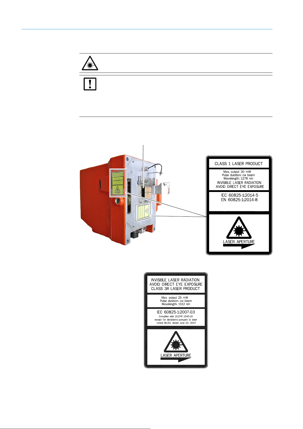
Laser outlet
Laser warning sign
1.1.4 Protection against laser radiation
WARNING: Eye injuries possible due to laser radiation
Observe all relevant information in these Operating Instructions.
NOTE: Deviations of EN60825-1:2014-08 “Laser safety” from the Directive
2006/25/EC
Due to the Implemented health and safety regulation for artificial optical radiation
concerning the Directive, deviations of EN60825-1:2014-08 “Laser safety” from
Directive 2006/25/EC have occurred.
▸ Always observe the user information in the Annex of these Operating Instructions!
“User information “Laser safety””, page 97.
The GM700 laser warning sign is located on the sender/receiver unit.
Fig. 1: Laser warning sign on the GM700 sender/receiver unit
12
Fig. 2: Laser sign for NH
measurement
3
8010100/YK22/V4-0/2015-12 | SICKOPERATING INSTRUCTIONS | GM700
Subject to change without notice
Page 11
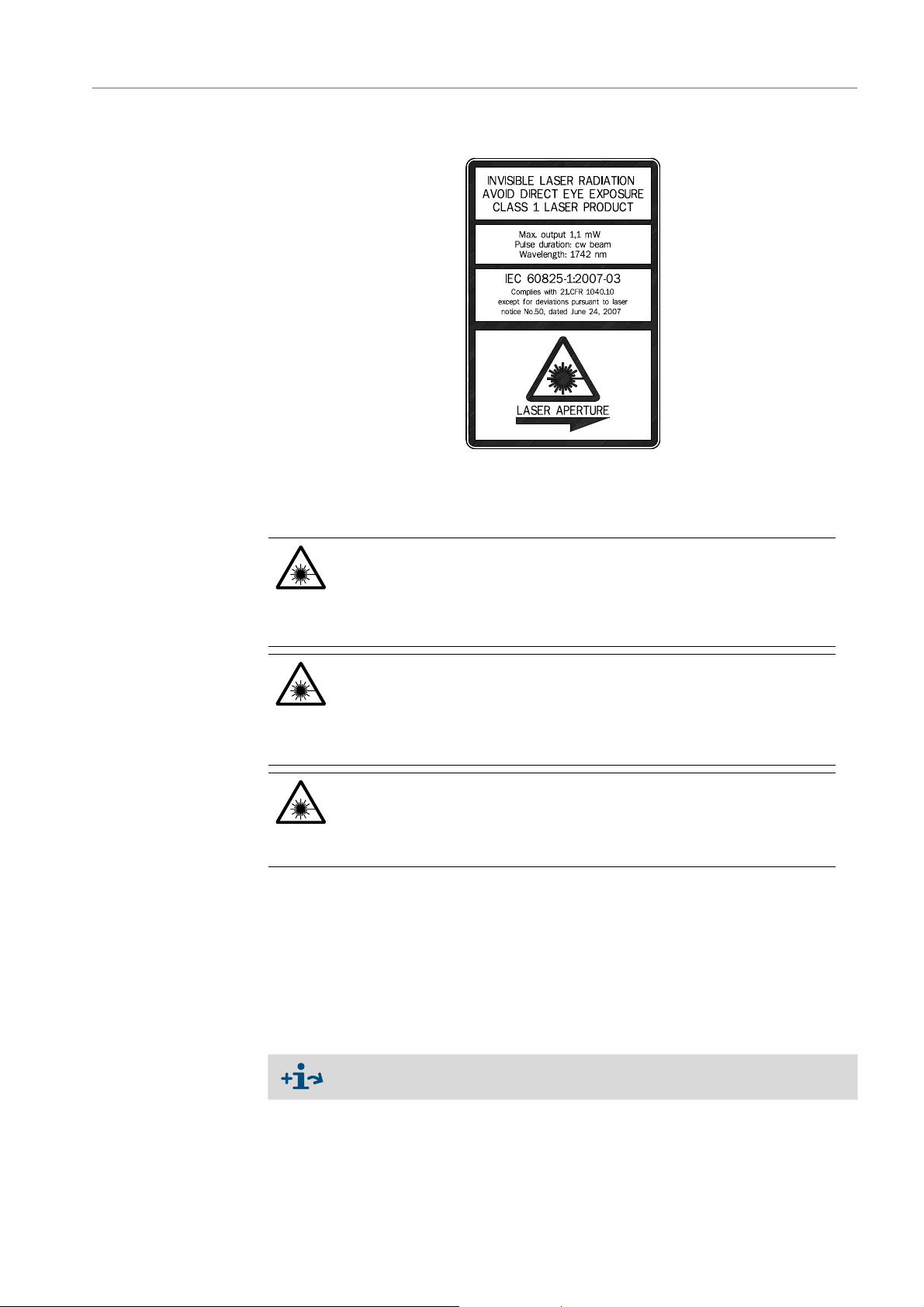
SAFETY INFORMATION 1
Fig. 3: Laser sign for HCI measurement
The invisible laser beam within the SR-unit is not accessible when fitted. There is no risk for
the human eye when looking into the optic visor on the right side of the SR-unit.
CAUTION: Observe the following for the GM700 HF version:
As the limit values of laser class 1 of the IEC 60825-1:2014-5 are neither exceeded
in single case malfunctions nor normal operation under consideration of the service
and measuring state, the device is classified as laser class 1.
Requirement: Use of device software 9105060_YEK0 or a newer software version
with equal functionality.
CAUTION: Important information for safe handling of the GM700 SR-unit HF
version
For device software versions older than 9105060_YEK0, a higher laser radiation
might occur.
▸ Laser class 1 of the IEC 60825-1:2014-5: Only use device software
9105060_YEK0 or a newer software version.
CAUTION: Important information for safe handling of the GM700 SR-unit
(all versions)
▸ Never look directly into the output lens when opening the SR-unit or the reflector.
▸ Always wear laser goggles or switch the device off during maintenance work.
▸ Observe valid national limit values and respective standards for work safety.
Laser capacity
The wavelength of the laser varies for the respective measuring components (NH
HCl).
The maximum laser output capacity on the optical interface (front window) depends on the
respective measuring component and is shown on the laser warning sign.
–HF: “Laser warning sign on the GM700 sender/receiver unit”, page 12.
–NH
: “Laser sign for NH3 measurement”, page 12.
3
– HCI: “Laser sign for HCI measurement”, page 13.
, HF,
3
The emitted radiation is harmless to human skin.
8010100/YK22/V4-0/2015-12 | SICK OPERATING INSTRUCTIONS | GM700
Subject to change without notice
13
Page 12

1 SAFETY INFORMATION
1.1.5 Behavior during purge air failure
GM700 measuring system configurations demand immediate or short-term measures to
protect the measuring system should the purge air supply fail.
Measures for purge air feed failure
▸ Refer to Purge Air Unit Operating Instructions.
1.2 Intended use
1.2.1 Purpose of the device
The gas analyzer GM700 measures the sample gas component concentration, e.g. HF,
NH3 or HCl in a gas mixture (sample gas). For this purpose, the GM700 analyzer is
assembled at the measuring location and measures directly onsite (in-situ measurement).
!▸
Do not use the device to expose persons to radiation.
1.3 Responsibility of user
Intended users
The GM700 may be operated by competent persons only who, based on their devicespecific training and knowledge of the device as well as knowledge of the relevant
regulations, can assess the tasks given and recognize the dangers involved.
Correct use
▸ Use the device only as described in these Operating Instructions. The manufacturer
bears no responsibility for any other use.
▸ Carry out the specified maintenance work.
▸ Do not remove, add or change any components in or on the device unless such changes
are officially allowed and specified by the manufacturer. Otherwise
– the device may become dangerous
– the manufacturer’s warranty becomes void
– the approval for usage in potentially explosive atmospheres becomes void.
Special local requirements
Follow local laws, regulations and company-internal operating directives applicable at the
installation location.
Responsibility for dangerous substances
WARNING: Mortal/health danger as a result of a gas path leakage
When the device is used to measure toxic gases: A leak, for example in the purge air
supply, can be an acute hazard for persons.
▸ Take sui tab l e sa fet y me asu res .
▸ Make sure these safety precautions are followed.
Safety precautions examples:
● Marking the device with warning signs
● Marking the operating area with warning signs
● Safety-related instruction of personnel who could be in the vicinity of the installation
site.
14
Retention of documents
▸ Keep these Operating Instructions available for reference.
▸ Pass on to a new owner/operator.
8010100/YK22/V4-0/2015-12 | SICKOPERATING INSTRUCTIONS | GM700
Subject to change without notice
Page 13

1.3.1 Disposing of device parts harmful to the environment
DANGER: Possible materials harmful to the environment and health
GM700 components can have small shares of pollutants or hazardous substances
such as low lead content in printed circuit boards. The optional permanent cuvette
contains low concentrations of HF or HCl (according to device configuration, see scope
of delivery).
▸ Dispose of all GM700 components according to local laws, regulations and
company-internal operating directives applicable at the installation location such as:
▸ Printed circuit boards and similar electronic components
▸ Dispose of the permanent cuvette, when fitted, safely because it contain low
concentrations of HCl or HF. Therefore, do not simply destroy the cuvette.
SAFETY INFORMATION 1
8010100/YK22/V4-0/2015-12 | SICK OPERATING INSTRUCTIONS | GM700
Subject to change without notice
15
Page 14

2 PRODUCT OVERVIEW
2Product Overview
2.1 Product identification
Product name: GM700
Device versions GM700 version with probe
Manufacturer:
Type plates:
GM700 version: Measuring component:
GM700-2 HF
GM700-3 HCI
GM700-5 NH
GM700-8 HCI / H2O
GM700-9 NH
SICK AG
Erwin-Sick-Str. 1 · 79183 Waldkirch · Germany
● SR-unit: On the right side
● On the purge air fixture
3
O
3/H2
16
8010100/YK22/V4-0/2015-12 | SICKOPERATING INSTRUCTIONS | GM700
Subject to change without notice
Page 15
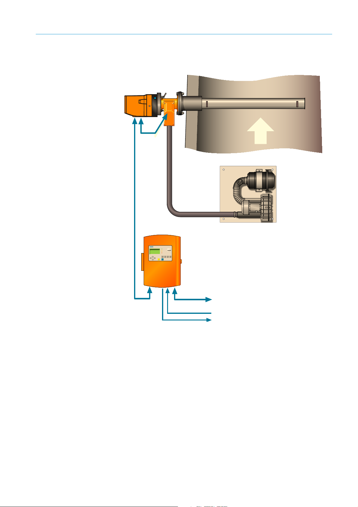
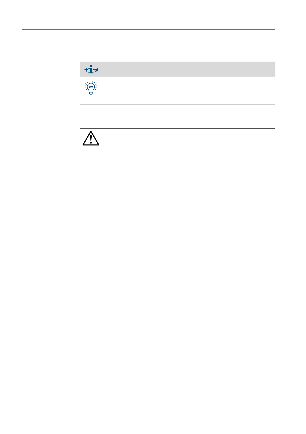
2.2 GM700 system, measuring probe version, layout
maintcalpardiag
GM
Evaluation Unit
CO
CO
2
H2O
mg/
m
3
236
Ref. conditions
Hum: wet
Measuring
Operation
Service
Warnin
Malfunction
Sender/receiver unit
with GMP measuring probe
Evaluation unit
EvU
CAN bus
CAN
Inputs/outputs,
analog, binary
Interfaces to plant peripherals:
● Measured data processing
● Status signals
Purge air unit SLV 4
(not fitted for GPP
probes)
Fig. 4: GM700 system overview (measuring probe version)
PRODUCT OVERVIEW 2
8010100/YK22/V4-0/2015-12 | SICK OPERATING INSTRUCTIONS | GM700
Subject to change without notice
17
Page 16

2 PRODUCT OVERVIEW
Sender/receiver unit (SR-unit)
The sender/receiver unit contains the optic and electronic subassemblies of the
measuring system. The gas concentration is captured here and the measured value
determined.
Measuring probe
Measuring probes are available in open design versions with integrated purge air guidance
system (GMP) as well as versions with a gas permeable sinter filter not requiring purge air
(GPP: G
detail”, page 19 onwards.
Purge air unit
To supply purge air to the SR-unit with open measuring probe (GMP) and thus to protect
against contamination and high gas temperatures. Use a certain purge air unit each for the
SR-unit depending on the application. The blower types for the SR-unit are designed
differently depending on the application.
as Permeable Probe). Both versions are described from “Measuring probe in
Further information on the purge air unit
▸ Refer to Purge Air Unit Operating Instructions.
Evaluation unit
The evaluation unit in the GM700 measuring system serves as user interface and is
responsible for measured value processing and output as well as control and monitoring
functions. The EvU can be located in the vicinity of the SR-unit. It can also be located up to
about 1000 meters from the sampling point, e.g. installed in the switch center or
monitoring center, and performs functions such as:
● Output of measured values, computed data and operating states
● Communication with the peripheral equipment
● Output of error messages and other status signals
● Control of automatic test functions and access during service (diagnosis)
Connection cables
Cable type Part No.
Cable (CAN bus) SR-unit – purge air fixture measuring probe, length 0.8 m 2 023 704
● Cable (CAN bus), SR-unit – evaluation unit, length 4 m
● Extension up to 1000 m, with terminal box ; with 24 V supply
[1]
Cable
(only for version Cross-Duct and GMP probe)
2 cables
extension (only for GMP probe)
Cable SR-unit purge air fixture – filter monitor of purge air unit, length 3 m
extension (only for Cross-Duct and GMP probe version)
Tab le 1 : Connection cable Part Nos.
[1] One length included in scope of delivery
[2] Included in scope of delivery
SR-unit purge air fixture – filter monitor of purge air unit, 5 m
[2]
SR-unit purge air fixture - filter monitor of purge air unit, length 2 m
● Scope of delivery
● Option: 2020440
2 032 143
6 025 923
6 028 663
18
8010100/YK22/V4-0/2015-12 | SICKOPERATING INSTRUCTIONS | GM700
Subject to change without notice
Page 17
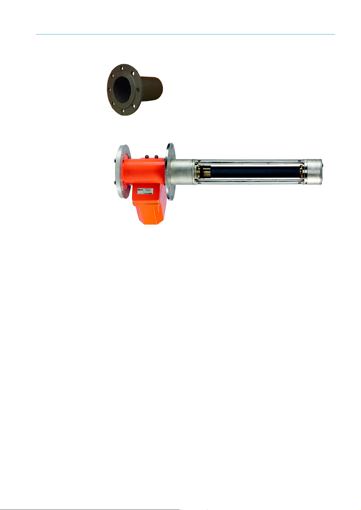
Flange with tube
2.2.1 Measuring probe in detail
Fig. 5: GPP measuring probe with ceramic filter
PRODUCT OVERVIEW 2
To install the purge air fixtures of the SR-unit and reflector on
the gas duct. The purge air fixture is fitted on the flange and
then the SR-unit is fitted on the purge air fixture. ANSI or DIN
flanges provided by the customer can be used alternatively to
the flanges supplied.
Integrated sensors
All probe versions have a built-in pressure sensor as well as an integrated temperature
sensor PT 1000 that continually measures the medium temperature of the probe in the
active measuring path. The measured data are transferred via the CAN bus interface of the
measuring probe and can then be displayed on the evaluation unit.
EPA conformity
When using a GPP probe, an audit measurement conforming to EPA CFR 40 Part 60 and/
or Part 75 can be carried out with the device fitted as far as usable for the application.
8010100/YK22/V4-0/2015-12 | SICK OPERATING INSTRUCTIONS | GM700
Subject to change without notice
19
Page 18
2 PRODUCT OVERVIEW
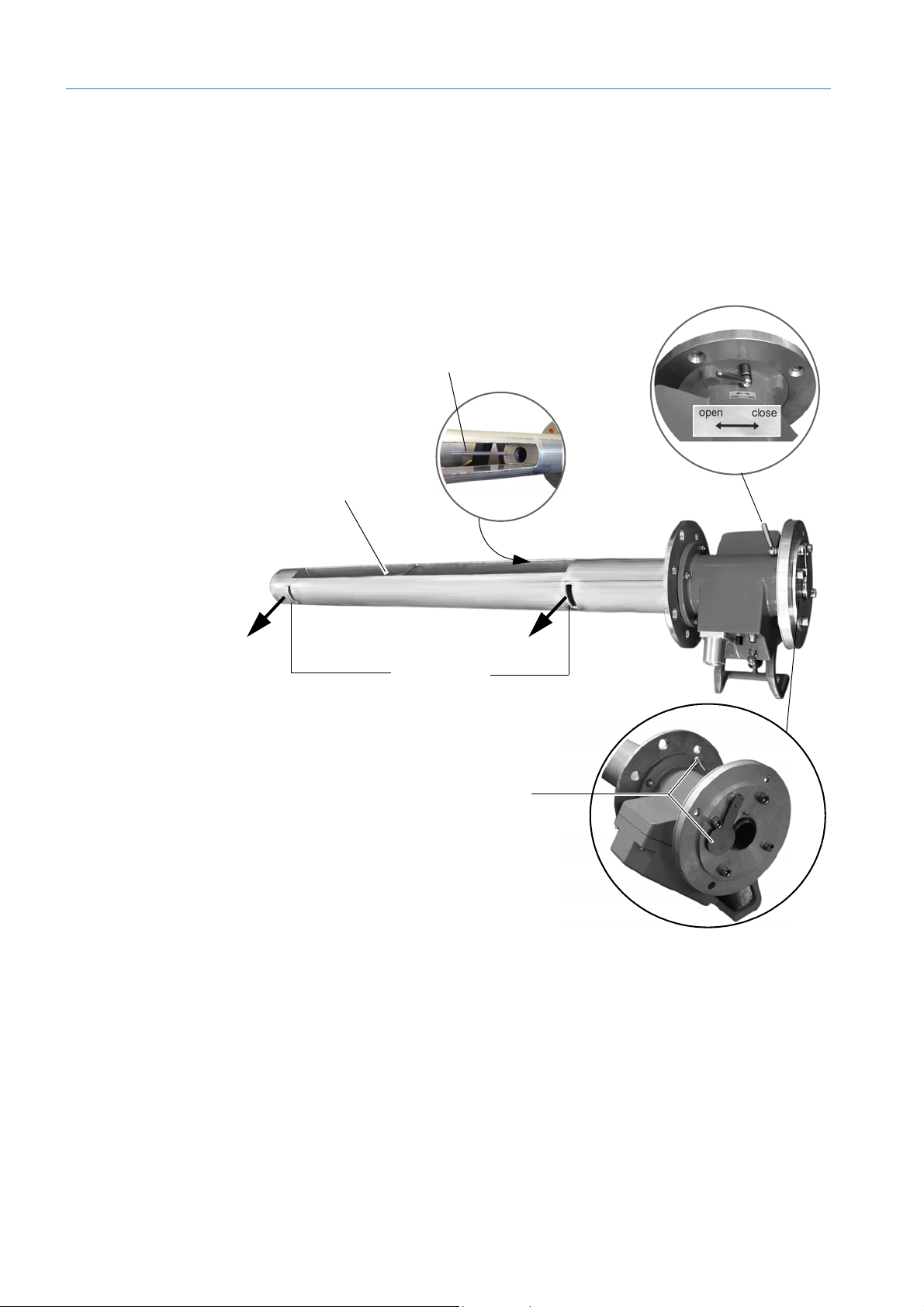
Temperature sensor
PT 1000
Purge air outlet
Open measuring
path (measuring
gap)
Lever position
Lever and locking device:
Open
2.2.1.1 GMP probe with open measuring gap
Shortest reaction times and high temperature stability characterize the GMP series
measuring probes. Continuous purge air feed is required for operation. In the current GMP
probe series, the air is outlet into the duct at 90° to the gas flow (directed purge air). The
GMP probe has a locking device on the opening for sample gas that is activated with a
lever on the probe flange.
Fig. 6: GMP measuring probe (with open measuring gap)
20
8010100/YK22/V4-0/2015-12 | SICKOPERATING INSTRUCTIONS | GM700
Subject to change without notice
Page 19
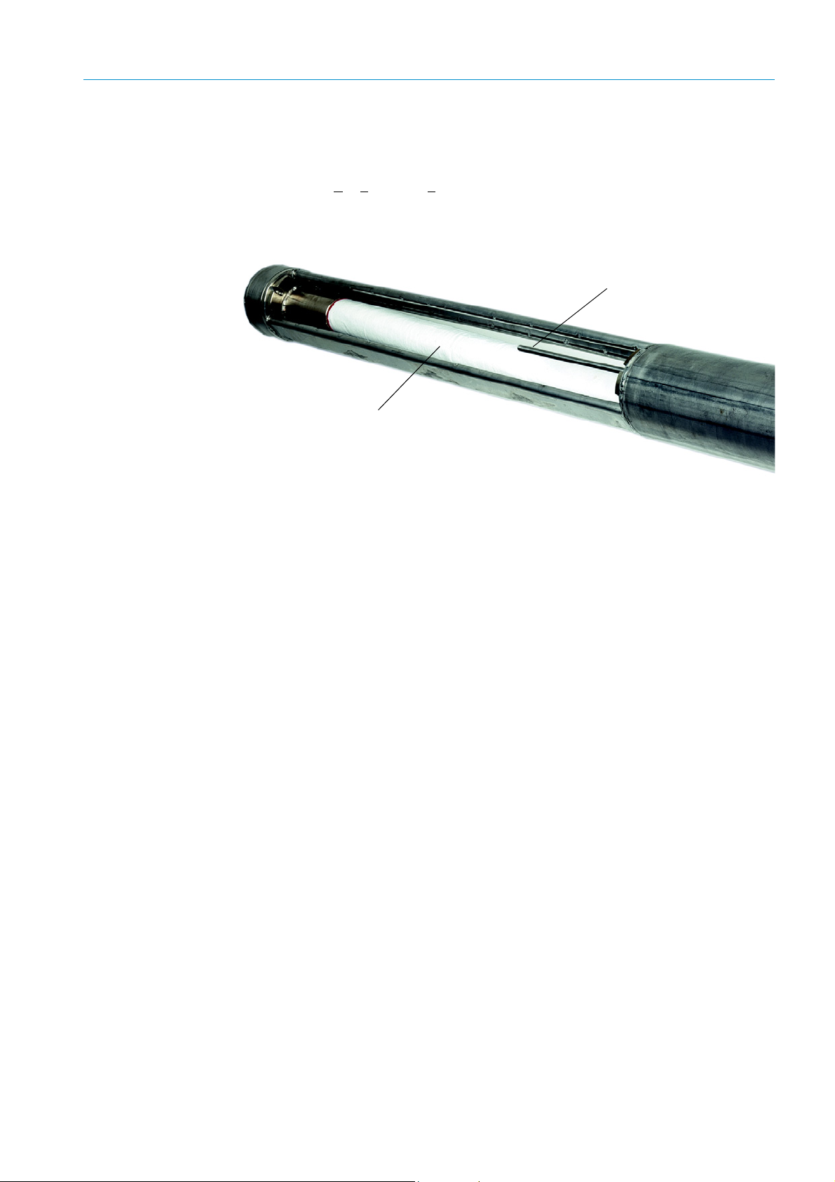
2.2.1.2 GPP gas diffusion probe in dry or wet version
Temperature sensor PT 1000
Gas permeable ceramic filter
This version is more suitable for higher dust contents because, on GPP probes, dust
particles are separated on the filter element and therefore kept away from the measuring
path. The GPP (G
as Permeable Probe) should also be chosen to allow an EPA-conform
audit measurement as well as for low flow speeds or irregular flow profiles.
Fig. 7: Measuring gap of the GPP measuring probe
PRODUCT OVERVIEW 2
Both variants of the GPP differ in the respective filter which provides suitability for different
application areas in accordance with Table “GM700 measuring probes in comparison”,
page 22.
Advantages of GPP probes
GPP probes do not require a purge air supply and are easy to maintain. They are fitted with
an automatically controlled heater to reliably prevent condensate on the optical interfaces.
The electronics for heating control, temperature and pressure measurement are located
reliably protected in a sturdy cast-metal enclosure acting as measuring probe section
between duct flange and SR-unit. Both the electric connections for CAN bus and power
supply as well as the test gas connection with which the audit measurement according to
EPA Guideline CFR 40, Part 60 or Part 75 can be carried out are located on the enclosure
as shown.
8010100/YK22/V4-0/2015-12 | SICK OPERATING INSTRUCTIONS | GM700
Subject to change without notice
21
Page 20

2 PRODUCT OVERVIEW
2.2.1.3 GM700 measuring probes in comparison
This Table shows an overview of the features of the different measuring probes. All
measuring probe versions are compatible with all SR-units. The SR-unit is calibrated to the
respective probe length before delivery.
Measuring probe GMP (open probe) GPP (dry)
Design
Max. gas temperature. 430°C
Gas check according to EPA
specification possible
Purge air supply required Yes –
Heating on optical interfaces in
the probe
Flow rate of sample gas 1...40 m/s < 40 m/s
Suitable for wet sample gas Yes –
Maximum duct pressure
Measurable components NH
System-response time (T90) ≥ 5s ≥ 120 s
Duct diameter
Dust concentration <2g/m
Probe lengths available [m] 1.0/1.5/ 2.0 1.0/1.5 / 2.0
Active measuring paths available
[mm]
Tab le 2 : Measuring probes in comparison
[1] The maximum temperature used for the measurement depends on the application.
[2] As from gas temperature 300 °C
[3] As from a gas temperature of minimum 130 °C
[4] Probes with shorter active measuring paths on request (possibly required for higher concentrations or
narrower duct diameters)
[4]
Measuring path open in flow
direction; purge air guidance
with outlet aligned 90° to gas
flow
[1]
Gas diffusion probe with
ceramic filter, for dry sample
gas
–Yes
– Yes, with integrated control
±120 hPa, depending on purge
air supply
, HF, HCl NH
3
±120 hPa
[2]
, HCl
3
[3]
> 360 mm > 300 mm
3
act. <30g/m3 act.
250/500/750/1000/1250 250/500/750/1000
2.2.1.4 Special versions
Apart from the standard probes shown, other versions made from stainless steel type
1.4539 especially resistant to acid are available. Special versions can be manufactured
according to customer demands on request.
2.3 GM700 options and accessories
● Terminal b ox for CAN bus with 24 V power supply
The optional terminal box is available for distances between SR-unit and EvU larger than
4 meters via a CAN bus cable provided by the customer. The total length of all the CAN
bus connections in the GM700 measuring system can be up to 1000 m in this case.
● Cover plate for purge air fixture of the sender/receiver unit
To maintain purge air supply in cases where this must remain in operation at the
measuring location when the SR-unit is dismounted.
● Weatherproof cover for SR-unit and purge air unit
Required for outdoor installation - dimension drawings, see “Dimensions of weatherproof
cover for GM700 SR-unit”, page 89.
22
8010100/YK22/V4-0/2015-12 | SICKOPERATING INSTRUCTIONS | GM700
Subject to change without notice
Page 21

● Chart recorder, single or multi-channel, for measured value recording. Protocol(s) can of
course be produced using customer systems.
● Air heater for purge air supply
For special application conditions to prevent condensate. An air heater is required when
the difference between gas temperature and dew point temperature is too small. The
following practical rule of thumb serves as guideline:
An air heater is recommended when
Gas temperature [°C] – dew point temperature [°C] < abs. humidity [%].
Values are compared without considering the units of measure.
2.4 Measuring principle
The light of the laser diode radiates through the sample gas and is then detected by a
photo diode. The laser diode wavelength is set to a single absorption line of the sample gas
component. This absorption line is scanned by modulating the wavelength and then the
transmission signal (relation between signal sent and received) captured by a photo diode.
An appropriate signal evaluation returns the magnitude of the absorption line from which
the gas concentration is then calculated. This method is called Tunable Diode Laser
Spectroscopy (TDLS) or Tunable Diode Laser Absorption Spectroscopy (TDLAS).
A laser specially developed for gas analysis is used as light source in the GM700. This laser
diode radiates a wavelength with a narrow line width so that an absorption line can be
reliably scanned. A Peltier element and a temperature sensor fitted in the laser diode
enclosure ensure a precise temperature and therefore exact wavelength stabilization of the
system.
PRODUCT OVERVIEW 2
The laser beam from the sender/receiver unit travels through the active measuring path
and then impinges on the reflector on the other side of the gas duct. The beam is then
reflected back to the sender/receiver unit. After the beam has passed through the
measuring path twice, during which laser light absorption specific to the gas occurs, the
light is focused on a receiver optics.
2.4.1 Reference cuvette for wavelength stabilization
The GM700 is equipped with:
● A permanently filled cuvette for the adjustment of the analyzer laser diode to the
reference position of the gas absorption line (Line-Locking).
2.4.2 Signal evaluation
The optimized algorithms of the GM700 evaluation electronics process the measurement
signal of the receiver element together with the corresponding parameters based on the
TDLS measuring method. This is based on the physical characteristics of the gas
molecules that absorb light energy in certain wavelengths. These optimized algorithms
ensure the concentrations of sample gas components are determined without crosssensitivities to other gases. The differential absorption measurement also eliminate dust
influences.
8010100/YK22/V4-0/2015-12 | SICK OPERATING INSTRUCTIONS | GM700
Subject to change without notice
23
Page 22

3 PROJECT PLANNING INFORMATION
3 Project Planning Information
3.1 Work steps from system selection to start-up
Application changes
If you make changes to the specifications ordered for your application or if a device is to be
used for an application different to the one originally planned, please pass this information
onto your local sales representative so that we can determine the application options
under changed conditions and whether new adjustment/parameter settings are required.
The following steps are normally taken before starting-up the measuring system
● Project planning
“Project Planning Checklist”, page 24.
● Initial onsite installation
▸ The following preparatory work normally carried out by the customer is described in
“Initial onsite installation”, page 27:
▸ Flange installation, “Installing the flanges with tube”, page 28.
▸ Preparation for installing the purge air unit, “Installation preparation for the purge air unit
(for GMP probe)”, page 30.
▸ Laying the signal and power supply cables to the measuring point, “Signal and power
supply cables”, page 31.
● Installation preparation for the EvU, “Electrical connection in the evaluation unit EvU”, page 40
▸ Possibly preparation of signal cables for the interface to the peripheral equipment,
“Signal and power supply cables”, page 31.
● Device installation
To allow speedy start-up, the following components are normally installed ready for
operation before the start-up date; see also “Installation”, page 34.
– Purge air unit
– Evaluation unit(s).
● Start-up
The actual start-up is carried out by trained personnel or Customer Service. This work is
described in “Start-up”, page 46. The main activities are adjustment tasks on the
GM700 system related to the application.
3.2 Project Planning Checklist
Project planning, step by step
The following Checklist simplifies performing and controlling project planning measures
required before start-up in the correct sequence. Technical data and dimensional drawings
of system components, see “Dimension drawing”, page 85 and following.
24
8010100/YK22/V4-0/2015-12 | SICKOPERATING INSTRUCTIONS | GM700
Subject to change without notice
Page 23

PROJECT PLANNING INFORMATION 3
D
4F (Cross-sectional area)
U (Circumference)
-------------------------------------------------------------------------------------=
Top ic Tas k Measure/determination
Provide for unhindered inlet and outlet paths:
▸ For round duct cross-sections: 3 times the duct diameter
▸ For rectangular cross-sections: Hydraulic diameter
▸ If these specifications cannot be met: Inlet section > outlet section,
2
/3 : 1/3; uniform concentration spread whenever possible
e.g.
Determine sampling point
Observe national regulations
such as VDI 3950
Emission sampling
point
Application conditions
Pressure conditions at
the sampling point
▸ Obtain official approval for emission sampling point.
▸ Provide for calibration openings at an easily accessible place.
▸ Ensure the GM700 and calibration probe do not influence each
other; the calibration gland should be located at a minimum
distance of 0.5 m away from the measuring device, upstream
▸ Observe Technical Data for duct/ambient conditions!
▸ Gas temperature above/below dew point (dry/wet)
▸ A fitting location with partial vacuum in the duct is ideal.
▸ For duct pressures > 10 mbar, contact SICK on correct selection of
the purge air blower.
▸ Flange fitting is planned in steel ducts as standard; corresponding
flanges with tube are normally included in the GM700 scope of
delivery.
▸ Stone stacks or ducts with thick walls demand an onsite retaining
plate and, possibly, a longer version of the flange with tube; “Install-
ing the flanges with tube”, page 28.
● “Dimension drawings of flange with tube”, page 89.
▸ Provide an opening of suitable size for the flange tube.
▸ Plan adequate clearance for installation and maintenance activities
for the duct insulation cutout.
▸ Plan clearances for handling the SR-unit
▸ Ensure the ambient temperature for the SR-unit is within the
specified range.
SR-unit
→
p. 25, §3.3.1
Select suitable flange
with tube
Duct openings
selection
▸ For installation outside, plan a weatherproof cover
Tools for start-up and
maintenance
▸ When working on the zero path; prerequisites: Clean ambient
atmosphere free from sample gas; weatherproof: Plan the zero
path or order from SICK.
▸ Plan installation location on the duct in immediate vicinity (5 m) of
the GM700 SR-unit.
▸ Keep purge air hoses to the purge air fixture (SR-unit) as short as
possible (pressure loss approx. 1.2 mbar per meter).
Purge air unit
→
p. 28, §3.3.4
Fitting location
selection
▸ Ensure secure cable laying.
▸ Ensure dry and, whenever possible, dust-free intake air on the
purge air unit, use a preliminary filter as necessary.
▸ The intake air temperature should be between 0 and 55 °C. Heat
the purge air for T < 0 °C; see air heater option ( “GM700 options
and accessories”, page 22).
▸ For installation outside, plan a weatherproof cover
Evaluation unit
→
p. 28, §3.3.6
Determine the fitting
location
Tab le 3 : Project Planning Checklist
▸ Plan assembling the unit at an easily accessible location
▸ Ambient temperature within the specifications, “Technical data
GM700 probe system”, page 80.
8010100/YK22/V4-0/2015-12 | SICK OPERATING INSTRUCTIONS | GM700
Subject to change without notice
25
Page 24

3 PROJECT PLANNING INFORMATION
Topic Task Measure/determination
▸ Provide a suitable working platform for installation on the outside of
a duct/stack.
▸ The fitting location of the GM700 SR-unit should be about 1.3 to
1.5 m above the platform.
▸ The platform must be large enough, secured and positioned so that
all device parts can be accessed without danger. This is especially
important when fitting and removing the SR-unit
Installation platform
Accident prevention
Specify the installation
platform
▸ Applicable (national) regulations on accident prevention must be observed.
Tab le 3 : Project Planning Checklist
26
8010100/YK22/V4-0/2015-12 | SICKOPERATING INSTRUCTIONS | GM700
Subject to change without notice
Page 25
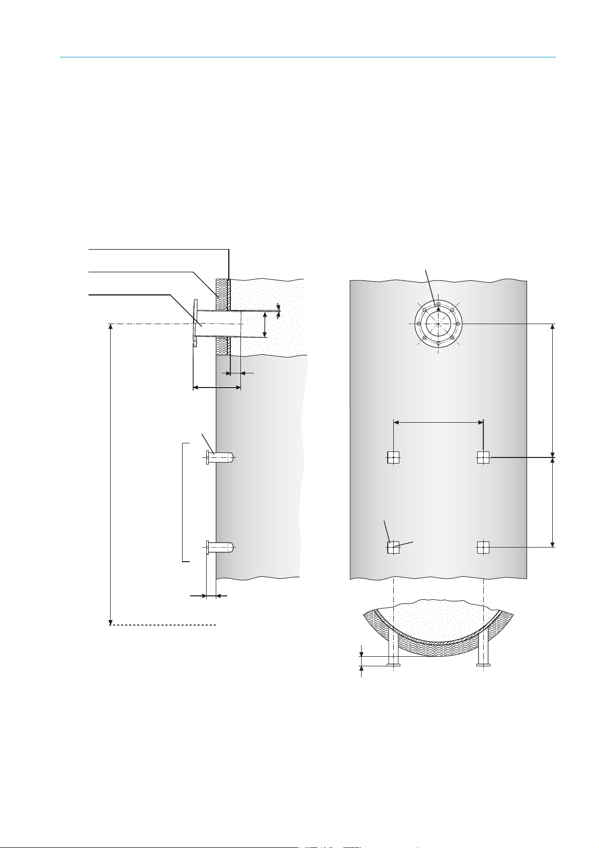
3.3 Initial onsite installation
30
L
50
470
M10
Ø13
3
1
FL. 60x8x60
D I N 174
min. 700
1,3 – 1,5 m
470
Duct wall (steel)
Duct insulation
Flange with tube,
standard: L = 240 mm
▴ : Marking for fitting position,
pointing in flow direction
Steel pipe
50 x 5
DIN 2391
Purge air unit fastening
Platform
50 mm protrusion for circular duct cross-section
The work described in the following can be carried out by the customer's installers.
Prerequisite is that all the required specifications have been made based on the Project
Planning Checklist.
3.3.1 Installation preparation at the sampling point
This Section describes the welding work on the duct including making fixing elements
onsite.
Fig. 8: Installation recommendation: Mounting flange and purge air unit (duct diameter not representative)
PROJECT PLANNING INFORMATION 3
8010100/YK22/V4-0/2015-12 | SICK OPERATING INSTRUCTIONS | GM700
Subject to change without notice
27
Page 26
3 PROJECT PLANNING INFORMATION
o
CAUTION: Protective measures at the sampling point
▸ Always shut down the installation before any work on the duct!
▸ Secure parts to be separated, e.g. with wire binding, to prevent damage caused
by falling par ts.
▸ Take appropriate protective measures against hot, explosive gases or toxic gases
that could possibly escape from the duct.
▸ Take all the necessary safety measures during welding work, among others
against the risk of explosion or fire in the duct atmosphere and on the duct
insulation.
▸ If necessary, seal off the mounting flange with a cover securely until device
installation (e,g, for overpressure in duct).
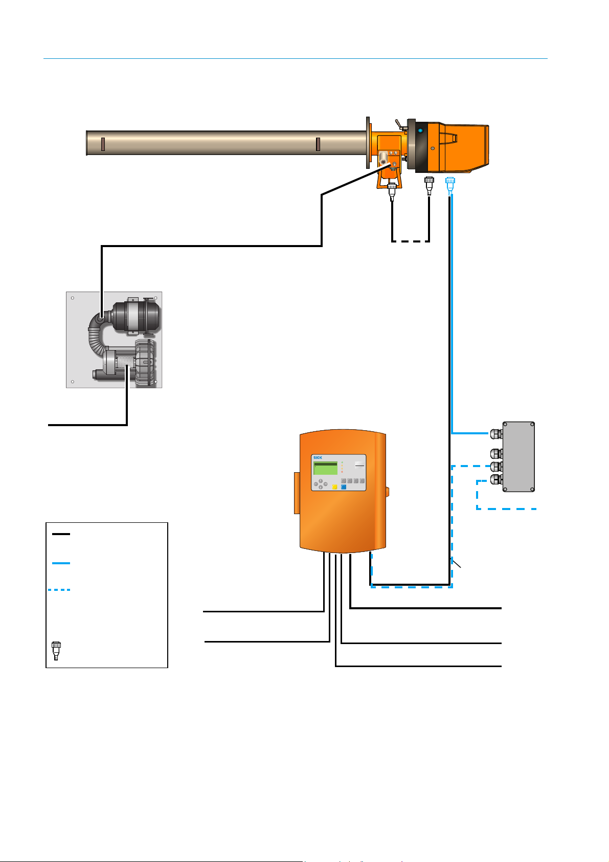
3.3.2 Uncovering the duct
▸ Remove any duct insulation to uncover an area of approx. 800 x 1500 mm (W x H) to
prepare the duct for the following work.
▸ Keep the insulation material removed for later refitting and/or provide new suitable
insulation material.
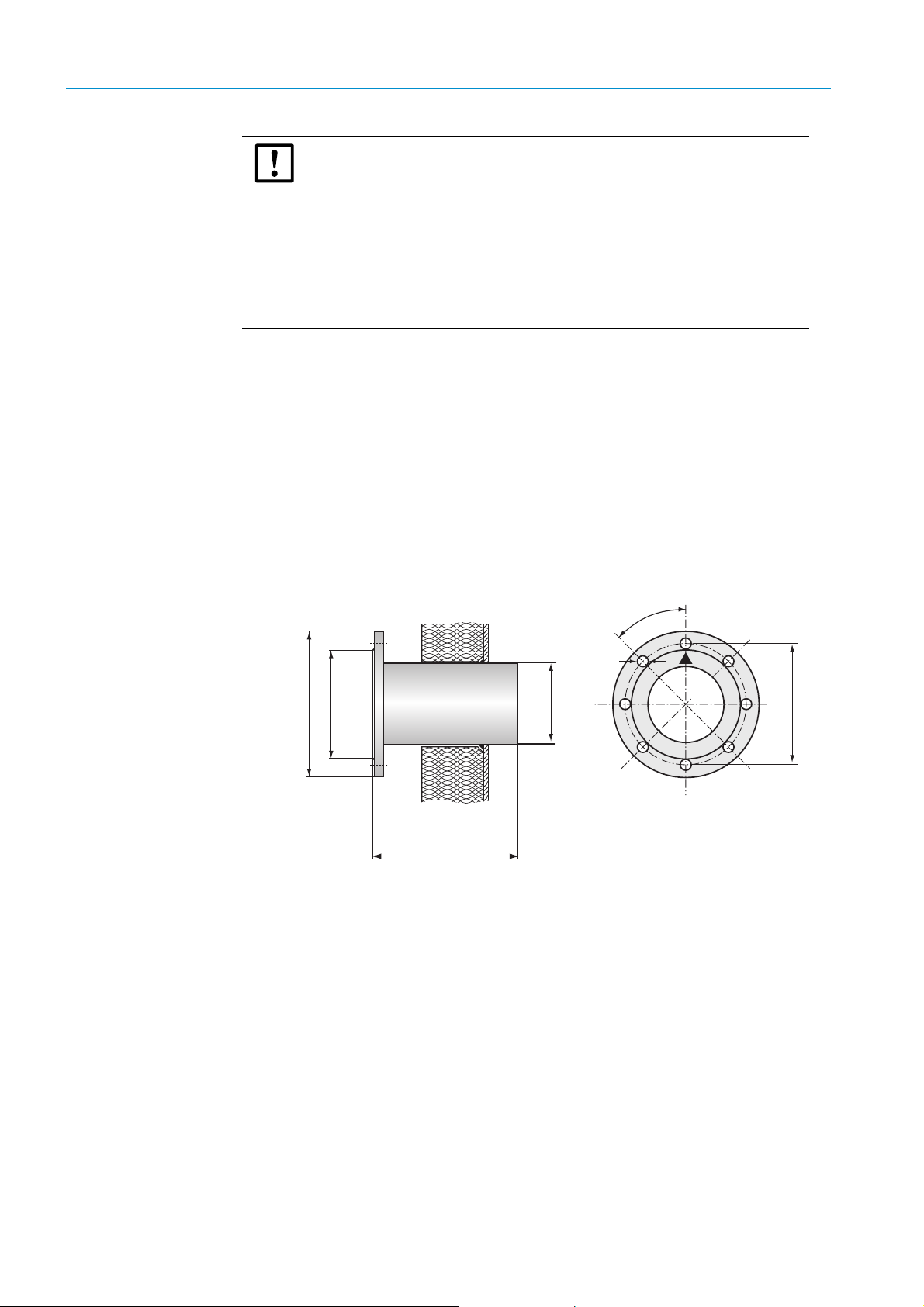
3.3.3 Installing the flanges with tube
SICK delivers two flanges with tube with 240 mm total length and 125 mm inner diameter
as standard. A version with 500 mm total length is available for installation locations with
thicker insulation or for stone stacks. Special versions can be manufactured on request.
Onsite flanges, including ANSI flanges, can also be used.
Fig. 9: Standard flange with tube
Reinforcement with junction plates recommended
Due to the weight of the sender/receiver unit, we recommend reinforcing the flange tube
fixture onsite with junction plates.
28
8010100/YK22/V4-0/2015-12 | SICKOPERATING INSTRUCTIONS | GM700
Subject to change without notice
Page 27
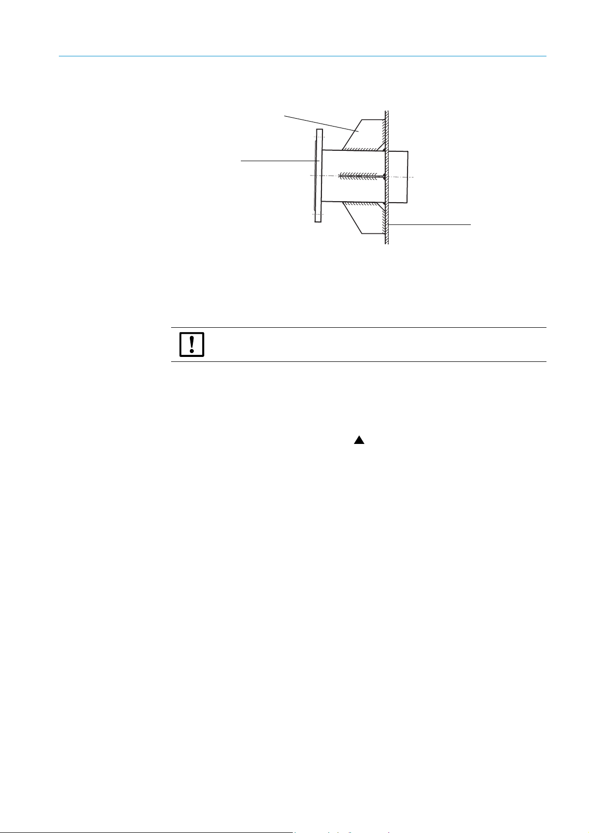
Fig. 10: Reinforcing with junction plates
Duct wall (steel)
Flange with tube
Reinforcing sheets (onsite)
Gas carrying duct made of stone/concrete
An additional retaining plate with suitable opening can be manufactured for ducts not
made of steel and in which the flange with tube can be welded.
3.3.3.1 Installing the flange with tube
PROJECT PLANNING INFORMATION 3
CAUTION: Always observe safety information on “Main hazards”, page 10!
1 Mark the flange center point exactly on the duct wall.
– On ducts made of stone/concrete: Cut the duct opening out approx. 2 cm larger than
the outer flange tube diameter; at the same time, plan a light downward incline of the
flange tube by approx. 1°. Provide a suitable retainer plate.
2 Cut an opening matching the outer flange tube diameter (standard Ø
= 133 mm) out of
a
the duct wall and/or retainer plate.
3 Position the flange tube so that marking points exactly in gas flow direction. Incline
the tube slightly downwards in the duct resp. on the retainer plate (approx. 1°, “Stan-
dard flange with tube”, page 28) to prevent condensate deposits later between tube and
probe.
4 Affix in the fitting position.
– Whenever possible, weld on junction plates as reinforcement; cf. “Reinforcing with
junction plates”, page 29. For ducts made of stone/concrete: Anchor the retainer
plate with flange with tube welded on securely to the duct.
5 Weld the flange tube on.
8010100/YK22/V4-0/2015-12 | SICK OPERATING INSTRUCTIONS | GM700
Subject to change without notice
29
Page 28
3 PROJECT PLANNING INFORMATION
3.3.4 Installation preparation for the purge air unit (for GMP probe)
● Maximum length of cable to measuring device complies with project planning.
Installation of purge air unit , see Operating Instructions of purge air unit.
NOTE: Adequate purge air pressure
▸ During project planning, make sure the purge air pressure is sufficient to force the
purge air into the gas duct. Please contact SICK Customer Service or your local
representative when necessary.
3.3.5 Duct insulation
▸ Refit the thermal duct insulation; reinforce the insulation when necessary.
WARNING: Observe the ambient temperature!
The SR-unit of the GM700 is designed for an ambient temperature of max. +50 °C.
Radiant heat on the enclosure surface can, among others, create temperatures higher
than the measured air temperature. Therefore, design insulation and radiation
shielding so that temperature limits are reliably maintained.
3.3.6 Installation preparation for the evaluation unit
The installation location for the evaluation unit was defined within the project planning
framework ( “Project Planning Checklist”, page 24). The maximum total cable length of all
CAN bus connections in the GM700 measuring system of 1 000 m was taken into account,
bearing in mind that the closer the device is to the measuring point, the easier it is to use.
Installation location preparation
The evaluation unit has fastening openings in the enclosure for easy fixing.
▸ Based on the EvU dimensional drawing according to “Dimension drawing evaluation
unit GM700: Sheet steel enclosure (dimensions in mm)”, page 88 and/or “Dimension
drawing evaluation unit GM700: Cast metal enclosure (dimensions in mm)”, page 88
ensure enough space is available at the planned installation location to attach these, for
wiring as well as opening the enclosure door.
▸ Drill suitable openings as installation points as required.
30
8010100/YK22/V4-0/2015-12 | SICKOPERATING INSTRUCTIONS | GM700
Subject to change without notice
Page 29

3.4 Preparations for electrical installation
The onsite supply and signal cables are laid beforehand to facilitate subsequent
installation and start-up of the GM700 system components. Suitable cable ducts and/or
empty conduits are installed for cables already prefabricated and delivered with the
GM700 system. Suitably qualified personnel or Customer Service connect the prepared
cables to the device during installation and/or start-up.
3.4.1 Signal and power supply cables
WARNING: Observe safety information!
● Always observe safety information and relevant safety regulations.
● During all work on electrical equipment, disconnect such equipment from the mains,
check that the equipment is potential free and make sure that no third person can
switch the equipment back on again without authorization. Leave the power supply
switched off during the following device installation.
● The power connection must be made via a circuit-breaker switch.
● The grounding cable must be connected.
PROJECT PLANNING INFORMATION 3
8010100/YK22/V4-0/2015-12 | SICK OPERATING INSTRUCTIONS | GM700
Subject to change without notice
31
Page 30
3 PROJECT PLANNING INFORMATION
maintcalpardiag
GM 35
Evaluation Unit
CO
CO
2
H2O
mg/
m
3
236
Ref. conditions
Hum: wet
Measuring
Operation
Service
Warnin
Malfunction
SR-unit
Measuring probe (example: GMP)
CAN *
0.8 m
Evaluation unit
CAN bus extension,
ready for connection, 15 m
(option)
CAN bus cable (standard), 4 m *
Terminal box (option)
Standard cable
connection
Cable connection,
option
Cable in scope of
delivery
*
Prefabricated with plug-in
connector(s)
Purge air unit SLV 4
(Standard for GMP measuring probe)
Power supply (230/115 V AC)
3 x 0.75 mm
2
3 binary inputs 6 x 0.5 mm
2
3 analog inputs 6 x 0.5 mm
2
3 binary outputs 6 x 0.5 mm
2
3 analog outputs 6 x 0.5 mm
2
to extend the CAN bus
connection with a cable
(1 x 2 x 0.5 mm2, twisted pair,
shielded) provided by the
customer
Cable connection for
optional terminal box
Power supply
115/230 V AC;
50/60 Hz
4 x 1.5 mm
2
(see safety information)
Signal cable for:
Filter monitoring of the SLV 4 – 2 x 0.6 mm
2
, on pressure
controller with flat pin bushings 6.3 x 0.8 mm (DIN 46247)
Pressure connection
Power supply 4 x 1.5 mm
2
(see safety information)
Fig. 11: Circuit diagram (probe version)
32
8010100/YK22/V4-0/2015-12 | SICKOPERATING INSTRUCTIONS | GM700
Subject to change without notice
Page 31

3.4.2 CAN bus wiring
PROJECT PLANNING INFORMATION 3
Standard cables
An installation location in the vicinity of the sampling point is generally selected for the EvU
so that the 4 m CAN bus cable in the scope of delivery is sufficient for cabling without
additional installation effort.
Installation away from the evaluation unit
A terminal box with a 24 V power supply unit can be delivered when the EvU is to be located
at a greater distance from the SR-unit. This is then connected to the SR-unit using the 4 m
CAN bus cable delivered with the measuring system. A customer cable suitable for CAN
bus applications, 6-pole cable (twisted pair wires and shielded), then leads to the EvU. The
total length of the CAN bus connections, including the one to the reflector, may be up to
1000 meters. When performing maintenance or service, it must be possible to deinstall
the EvU temporarily and connect it directly to the SR-unit at the sampling point.
Laying the cables
▸ Provide adequate cable lengths at the connection points.
▸ Whenever possible, do not lay power supply cables immediately next to signal cables.
▸ Protect open ends of preinstalled cables against weather effects until device
installation.
▸ Install separate power supply cables and circuit breakers for:
– Purge air units; additional motor circuit breakers and optional protective phase failure
switches.
– Evaluation unit
WARNING: Take precautions to prevent accidental switching off of the purge
air supply.
▸ Attach a clearly visible warning against accidental switching off the separation
equipment for the purge air unit.
▸ Install easily accessible cable ducts or empty conduits for the prefabricated cables to
those delivered with the system ( “Circuit diagram (probe version)”, page 32) marked
with one or two plug-in connectors . Approx. 2 m cable lengths each should be
available at the sampling point for later maintenance work on the measuring system
when dismounted from the duct.
▸ Lay onsite cables (shown without plugs) according to “Circuit diagram (probe version)”,
page 32.
– Wire cross-section specifications are recommendations from which cables for analog
and binary signals can slightly deviate (not however for the CAN bus connections
and/or power supply cables).
– Start with the system internal connections of the GM700.
Status and signal cables from the EvU to the connection terminals of the customer's
status/message devices can be added later as required.
8010100/YK22/V4-0/2015-12 | SICK OPERATING INSTRUCTIONS | GM700
Subject to change without notice
33
Page 32

4 INSTALLATION
4 Installation
4.1 Preparations
This Section describes the installation and installation work for the GM700 measuring
system before the actual start-up. Completion of the onsite preinstallation in accordance
with “Preparations”, page 34 is assumed.
4.1.1 Checking the scope of delivery
▸ Check the delivery against the belonging delivery note and make sure the complete
measuring system has been delivered as ordered.
▸ Check the specifications on mains voltage and frequency on the type plates of the
GM700 components match the installation conditions, delivery note and the order.
4.1.2 Installation prerequisites
The following prerequisites are applicable for the work described in the following:
▸ Plan safe usage/application within the limits defined in “Technical data GM700 probe
system”, page 80.
▸ Compliance with the specifications made during project planning (according to “Project
Planning Checklist”, page 24) and correct performance of onsite preinstallation
according to “Mechanical preparation”, page 47.
WARNING: Power supply OFF!
During the following work, it must be ensured that the power supply to the devices and
cables involved is switched off and can only be activated by the personnel carrying out
the work when the work is completed and/or for test purposes and then under
consideration of valid safety regulations.
34
8010100/YK22/V4-0/2015-12 | SICKOPERATING INSTRUCTIONS | GM700
Subject to change without notice
Page 33

4.2 Fitting system components
52
163
4.5
Mounting holes
4.2.1 Information on the SR-unit and measuring probe
The GM700 SR-unit and measuring probe are first fitted on the duct during start-up ( “Fit-
ting the SR-unit on the measuring probe”, page 48) because these components first
require an adjustment away from the gas-carrying duct. To avoid problems during start-up,
the SR-unit and measuring probe must be stored in a dry place free from dust, preferably
at room temperature, until start-up.
CAUTION: Do not fit the SR-unit and measuring probe before start-up
Unfavorable ambient conditions or atmosphere in the measuring channel can
damage the measuring system which prevents start-up.
Apart from that, there is a health risk when opening the duct depending on the pressure,
gas temperature and composition in the sample gas duct.
4.3 Installing the purge air units (for GMP probe)
Installation of purge air unit
→ Operating Instructions of purge air unit.
INSTALLATION 4
4.3.1 Terminal box with 24 V power supply unit (option)
▸ Install the terminal box with 24 V power supply unit in the vicinity of the sampling point.
▸ Secure the enclosure using both mounting holes (∅ 5 mm)
▸ The cable length available from the terminal box to the SR-unit is 4 m.Take the empty
conduits laid for the prefabricated cables during onsite preinstallation into account.
Fig. 12: Fitting the terminal box with power supply unit
8010100/YK22/V4-0/2015-12 | SICK OPERATING INSTRUCTIONS | GM700
Subject to change without notice
35
Page 34

4 INSTALLATION
4 mounting holes
∅ 8mm
Mounting surface
Fastening brackets
4.4 Installing the evaluation unit
The fitting location for the evaluation unit was defined during project planning ( “Project
Planning Checklist”, page 24) and prepared during onsite preinstallation as required.
▸ Make sure the CAN bus connection to the SR-unit selected during project planning is
usable at the planned installation location. The CAN bus connection cable delivered as
standard is 4 m long and serves to connect the evaluation unit directly at the sampling
point.
▸ Ensure easy access without problems. In particular, make sure the swivel door of the
evaluation unit can be opened without hindrance after fitting.
4.4.1 Installing the evaluation unit – sheet metal enclosure version
▸ Drill mounting holes ∅7.2 mm (for M8) at the fitting location according to the Drilling
plan.
▸ Attach the evaluation unit at the installation location using the 4 planned fastening
brackets with suitable screws.
Fig. 13: Installing the evaluation unit (sheet metal enclosure version)
36
8010100/YK22/V4-0/2015-12 | SICKOPERATING INSTRUCTIONS | GM700
Subject to change without notice
Page 35

4.4.2 Installing the evaluation unit – cast-metal enclosure version
117.5
330
235
Swivel door
Mounting holes ∅ 7.2 mm
Mounting surface
The mounting holes are
accessible when the swivel
door is open.
Mounting holes
∅ 7.2 mm
1.
2.
▸ Drill mounting holes ∅7.2 mm (for M8) at the fitting location according to the Drilling plan.
Fig. 14: Mounting holes layout (Drilling plan) to fit the EvU (cast-metal enclosure)
INSTALLATION 4
▸ Open the enclosure cover with a control cabinet key and swivel open.
▸ Attach the evaluation unit at the installation location using the 3 planned mounting
holes with suitable screws (M8 x 20).
Fig. 15: Fitting the evaluation unit (cast enclosure)
▸ Close and lock the cover again.
8010100/YK22/V4-0/2015-12 | SICK OPERATING INSTRUCTIONS | GM700
Subject to change without notice
37
Page 36

4 INSTALLATION
4.5 Electrical connection of system components
Onsite preparation for electrical installation has been described in “Preparations for elec-
trical installation”, page 31. The cables laid as described there are now connected to the
system components.
CAUTION: Observe safety information as well as relevant safety regulations!
During all work on electrical equipment, disconnect such equipment from the mains,
check that the equipment is potential free and make sure that no third person can
switch the equipment back on again without authorization.
Electrical connections for purge air unit → Purge air unit Operating Instructions.
4.5.1 CAN bus wiring options
As already described in the project planning on “Preparations for electrical installation”,
page 31, the following options are available for wiring the CAN bus connection between SR-
unit and evaluation unit:
● Standard cable, 4 m, prefabricated
● Terminal box with prefabricated 4 m long cable to SR-unit; a cable provided by the
customer is used to connect to the evaluation unit.
Information on selecting a suitable type of wiring can be found under “Circuit diagram
(probe version)”, page 32.
38
8010100/YK22/V4-0/2015-12 | SICKOPERATING INSTRUCTIONS | GM700
Subject to change without notice
Page 37

INSTALLATION 4
Fuse 2.5 AT
230 /115 V AC
40…60 Hz
ST 1
250 V
ST 2
3
2
1
PENL1
ST 5ST 6 ST 7
ST 4
PG 13.5
PG 13.5
CAN-L
+24
GND
CAN-H
CAN GND
NC
5
4
3
2
1
6
CAN-L
CAN-H
CAN GND
3
2
1
CAN-L
+24
GND
CAN-H
CAN GND
5
4
3
2
1
NC
6
CAN
Terminator
Power supply
115 V/230 V AC
Sensor
Evaluation unit
Sensor
Prefabricated cable with plug,
4 m long, to SR-unit
Cable to evaluation unit
(provided by customer)
Cable to power supply
(provided by customer) (see
safety information)
CAN cable signals
Color Signal
Pink +24 V
Grey GND
Yel low C AN- H
Green CAN-L
Brown CAN-GND
White n.c.
WARNING: Endangerment of electrical safety
● The power cables must be adequately dimensioned.
● The power connection must be made via a circuit-breaker switch.
● The grounding cable must be connected.
Wiring in terminal box
Connections in the terminal box are wired as follows:
Fig. 16: Terminal box for CAN bus connection between SR-unit and evaluation unit
▸ Connect bridge (jumper) according to suitable voltage supply (ST2).
▸ Lead CAN cable (provided by customer) through the right PG screw fitting to terminal
strip.
▸ Connect shielding on the PG screw fittings on the enclosure.
▸ Connect wires to terminal strip ST5 as shown in “Evaluation unit connections”, page 40;
check that a twisted pair cable is used for CAN-H and CAN-L. Connect the respective
signals in the EvU and terminal box.
8010100/YK22/V4-0/2015-12 | SICK OPERATING INSTRUCTIONS | GM700
Subject to change without notice
39
Page 38

4 INSTALLATION
+ – + – + –
+ – + – + –
+ –
+ – + –
PE
N
L1
PE N L1
V 42+
H NAC
L NAC
V 42+
+– +– +–
115/230 V AC;
50/60 Hz
(3 x 1.5
2
)
+– +– +–
12
12 3
Power
+5V +24V
Power CAN
+24V
+ – H L GND
Digital in
Analog i n
0.. 20mA
100 100 100
40..60Hz
230V
or
115V
AO1 AO2 AO3DI1 DI2 AI1 AI2 AI3
Sensor
DO1 DO2 DO3
Digital out
AC/DC 48V 30VA 1A
Analog out
0.. 20mA
Sensor
Fuse 2.5 AT 250V
PE N L1
contrast
Tp
Enter meas
diag par cal maint
Operation
Service
Warning
Malfunction
GM 35
Evaluation Unit
Plug this bridge for 115 V and/or 120 V
voltage supply.
48 V AC/DC; 60 VA,
1 A (6 x 0.75
2
)
relay outputs
0...20 mA (6 x 0.75
2
)
Analog outputs
0...20 mA (6 x 0.5
2
)
Analog inputs
Pot.-free contact (6 x 0.75
2
)
Digital inputs
Failure
1)
Maintenance request
2)
Function contr.
2)
(CAN H, L twisted
pair, shielded)
GM700 SR-unit
and/or terminal
box
Operating elements board
Connections board
Cast-metal enclosure shown
1)
N/C contact
2)
N/O contact
WARNING: Endangerment of electrical safety
● The power cables must be adequately dimensioned.
● The power connection must be made via a circuit-breaker switch.
● The grounding cable must be connected.
(see safety information)
4.5.2 Electrical connection in the evaluation unit EvU
Cable laying to the evaluation unit and relevant specifications have already been shown in
“Circuit diagram (probe version)”, page 32.
Fig. 17: Evaluation unit connections
40
8010100/YK22/V4-0/2015-12 | SICKOPERATING INSTRUCTIONS | GM700
Subject to change without notice
Page 39

INSTALLATION 4
3
4
2
1
CAN cable
shielding
PG screw fitting on the
evaluation unit
CAN bus cable
PG screw fitting on
the EvU
▸
Open enclosure door of evaluation unit.
WARNING: Observe connection values for power supply!
The evaluation unit is configured to 230 V AC on delivery.
▸ Plug the respective bridges for 115 and/or 120 V AC as shown on the connection
plate of the evaluation unit.
▸ Ensure the power supply has been installed (see evaluation unit connections) according
to the specifications (observe national requirements), but with the power switched off.
▸ Connect protective conductor (PE) to the terminal on the enclosure floor
▸ Lead the signal cable for inputs and outputs through the PG screw fittings on the EvU
enclosure floor and wire according to “Evaluation unit connections”, page 40.
▸ When using the CAN cable provided by the customer, connect the wires to the “Sensor”
terminal strip. Do not connect +24 V and GND (ground).
Fig. 18: See steps 1 to 4 below Connecting the CAN bus cable to the evaluation unit
WARNING: Burns by touching the cable glands
The temperature on the cable glands can be >60 °C.
8010100/YK22/V4-0/2015-12 | SICK OPERATING INSTRUCTIONS | GM700
Subject to change without notice
41
Page 40

5 HANDLING THE EVALUATION UNIT
GM700
Evaluation Unit
NH3
mg/
m
3
236
Operation
Service
Warning
Malfunction
GM
Evaluation Unit
NH3
mg/
m
3
236
Ref. conditions
Hum: wet
Enter meas
diag par cal maint
Measuring
Operation
Service
Warning
Malfunction
GM 35
Evaluation Unit
CO
CO
2
H2O
mg/
m
3
236
Ref. conditions
Hum: wet
Enter meas
diag par cal maint
Measuring
Measuring
Enter meas
maintcalpardiag
Operation
Service
Warning
Malfunction
Ref. conditions
Hum: wet
Graphic display for measured value
display and navigation
Status LEDs to indicate operating and
malfunction states
Key pad for navigation and
entering data
Key pad for menu selection
5 Handling the Evaluation Unit
5.1 User qualifications
This Section describes how to operate the GM700 measuring system with the evaluation
unit (EvU). The evaluation unit is available with either a sheet metal enclosure (protection
class IP 65) or a cast-metal enclosure (protection class IP 67). The work described in this
Section can be carried out by qualified customer operating personnel. Setting parameters
does however demand comprehensive knowledge of the measuring system, measuring
technology and specific measuring task.
5.2 Operating elements
The evaluation unit of the analysis system serves to display, enter and set parameters and
control functions on the system. The operator panel with the display, status indicators and
key pad is accessible when the enclosure door is opened.
Fig. 19: Evaluation unit display and operating elements (shown with sheet metal enclosure)
42
Arrow keys
Enter
Display in measuring
mode
Navigate, select, scroll or edit menu items, variables, units or digits.
Execute the selected menu contents or commands.
Displays all current measured values (temperature values resp, gas
concentration);
Displays computed values
8010100/YK22/V4-0/2015-12 | SICKOPERATING INSTRUCTIONS | GM700
Subject to change without notice
Page 41

LEDs
Measuring
T=150 °C
←
● Operation
● Service
● Warning
● Malfunction
Display contents
HANDLING THE EVALUATION UNIT 5
Measuring operation
Service mode
Warning messages, see Diagnostic mode (diag)
Device malfunction, error message, see Diagnostic mode (diag)
● The header line shows the selected operating mode (e,g,
parameter settings) or the menu items just selected during
navigation.
● 4 lines to show submenus, plain-text messages or settings
(values)
● Function line:
←
back Use button Arrow ← to return to next higher level
edit Enter Use button Enter to activate menu item or confirm
input
select Use button Enter to select a variable
↑ (↓) When selecting a variable requiring numeric input,
use buttons
per digit
Password When a password is prompted, enter the code
1 2 3 4 using↑ (↓).
Arrow ↑ (↓) to set the numeric value
5.2.1 Menu overview
Mode Menu
Measuring Measuring
operation
Diagnosis Malfunction
Warning
Sensor values
GM700 Sens. values
Sample Cross-Duct: OH
Parameters Setting
Physical
Unit
GM700
Cross-Duct Refl.
Component Unit:
Ref. condition:
Average Avg. Time:
Meas. Distance Active:
Gas Temperature Source:
Subst.
Pressure Source:
Subst.
Tab le 4 : GM700 menu overview
● Current measured values depending on device
version
● Reference variables (wet, dry)
● Current error messages (plain-text)
● Current warning messages (plain-text)
● Displays diagnostic values and control values
● Current monitored sensor values (amplification
setting, internal temperature control, control
values, etc.)
● Parameter settings/display of system
components
● mg/m
● t: actual, 25 °C, 20 °C, 0 °C
● p: actual, 1013 mbar
● Hum.: wet, dry
● 0 ... 300 s
● 200 ... 8000 mm
● Probe, Subst. Analog In
● –100 ... 2000 °C
● Probe, Subst. Analog In
● 600 ... 15000 hPa
3
, ppm
8010100/YK22/V4-0/2015-12 | SICK OPERATING INSTRUCTIONS | GM700
Subject to change without notice
43
Page 42

5 HANDLING THE EVALUATION UNIT
Humidity Subst.
Analog Out Live Zero
Output 1
Output 2
Output 3
Analog In Input 1 T
Input 2 p
Coefficients
Funct.
Span (HF)
Zero (HF)
Ambient Temp. Range
t (Feed Test Gas) Period
Check cycle Period
Zero Adjust Enable
Repet.
t (purge)
t (delay)
Delta T
Device Serial Number Head.
Laser
EvU
Software Revision
Tab le 4 : GM700 menu overview
● 0 ... 93.0 percent by volume
● 0, 4 mA
● Component: e.g. HF, - -, p, T
● Range low: 0 ... 999999
● Range high: 0 ... 999999
● Cycle Out: No, Yes
● Component: e.g. HF, - -, p, T
● Range low: 0 ... 999999
● Range high: 0 ... 999999
● Cycle Out: No, Yes
● Component: e.g. HF, - -, p, T
● Range low: 0 ... 999999
● Range high: 0 ... 999999
● Cycle Out: No, Yes
● Unit: °C, K, °F
● Live Zero: 0, 2, 4 mA
● Range low: 0 ... 15000
● Range high: 0 ... 15000
● Unit: hPa
● Live Zero: 0, 2, 4 mA
● Range low: 0 ... 15000
● Range high: 0 ... 15000
● 0.50 ... 1.99
● ±999
● 0 ... 50 °C, –10 ... 40 °C, –20 ... 30 °C, –30 ...
20 °C, –40 ... 10 °C
● 0 ... 3666 d (day)
Only when permanent cuvette fitted.
● 0 ... 24 h
● Yes, No
● 0 ... 24 h (only GPP)
● 0 ... 900 s; purge time until zero is executed
● 0 ... 1800 s; delay until gas enters again
● 0 ... 999 °C; temperature difference at which a
zero adjust is carried out
● _ _ _ _ _ _ _ _
● _ _ _ _ _ _ _ _
● _ _ _ _ _ _ _ _
● GMM700-X
● XXXXXXX XXXX
● GMM700/DSP
● XXXXXXX XXXX
44
8010100/YK22/V4-0/2015-12 | SICKOPERATING INSTRUCTIONS | GM700
Subject to change without notice
Page 43

HANDLING THE EVALUATION UNIT 5
cal
Service
Calibration Check cycle Start CCY (Check Cycle)
Zero Adjust Start ZeroAdjust Password
(1 2 3 4)
Zero Adj. Stack Start ZeroAdjust Password
(1 2 3 4)
Box measuring Start Meas. Password
(1 2 3 4)
Check cycle Start CCY (Check Cycle)
Mainte-
Maint. Mode Mode: Off, On
Adj. Opt. Align. Opt. Alignment
nance
Tes t Analog Out AO 1 : 4 m A
AO 2: 4 mA
AO 3: 12.5 mA
Test Analog In AO 1: 0 mA
AO 2: 0 mA
AO 3: 0mA
Test Relay Relay 1: On (Off)
Relay 2: On (Off)
Relay 3: Off (On)
Test Digital In DI 1: Open
DI: 2: Open
DI: 3: Open
Push Diag RS232
Reset System
Reset Parameter
Tab le 4 : GM700 menu overview
● Not defined
● Check cycle for test purposes, e.g. after
maintenance (preliminary)
● Zero point determination, e.g. during start-up
or af ter maintenance task based on the zero
path
● Only GPP probe:
Zero point determination with measuring
device on gas duct
● Check of measuring components with test gas
via a filter box
● Check cycle for test purposes, e.g. after
maintenance
● Maintenance operation: On, Off
● Displays optical alignment of SR-unit
● Tests the analog outputs
● Tests the analog inputs
● Tests the re lay ou tpu ts
● Tests the di git al i npu ts
● Outputs the complete parameter set via the
RS232 Service interface
● Restarts the measuring system
● Resets parameters to factory settings
Attention: All settings are overwritten!
8010100/YK22/V4-0/2015-12 | SICK OPERATING INSTRUCTIONS | GM700
Subject to change without notice
45
Page 44

6 START-UP
6 Start-up
6.1 Preparations
This Section describes the standard start-up at the end of which GM700 starts measuring
operation.
6.1.1 Required qualifications and further prerequisites
Previous training by SICK or a qualified sales partner is recommended for technicians or
engineers planning on performing a start-up. This training provides knowledge so that
participants can recognize and handle situations that demand measures going beyond the
standard procedures described here. Apart from the start-up itself, employees of SICK or
trained sales partners are also able to make recommendations for the actual measuring
operation as well as to define the maintenance interval based on the specific plant
conditions.
Standard start-up
Each individual measuring system is already configured to the individual usage conditions
at the factory and therefore the standard start-up procedure described in this Section can
normally be carried by qualified engineers or measurement technicians without the special
training. Prerequisites are:
● Exact adherence to the application requirements specified in the order
● The possibility, during start-up, to ask the advice of a trained specialist from SICK or the
respective sales partner should special questions arise that go beyond the normal
scope of the standard procedures described
Start-up procedure overview
After the general preparation which mainly deals with checking the work already carried
out, it is then necessary to carry out a zero adjust with the measuring system on a
measuring path free from sample gas, the zero path. This can be done either at the
sampling point or another location, e.g. in a closed room. At the sampling point itself, the
purge air unit and the SR-unit are then put into operation in succession. Finally, the
evaluation unit is switched on and checked; the parameters can then be set for the
individual demands.
6.2 Start-up steps overview
Prerequisites for successful start-up:
● Installation conditions match the requirements for the measuring system (temperature,
pressure).
● Sampling point must be accessible without danger or problems.
● All power supply and signal cables installed and connected.
● The system, apart from the SR-unit and purge air fixtures which are attached to the duct
flange later, must be fully installed and wired.
● Purge air supply, when fitted, must be ready for use.
46
8010100/YK22/V4-0/2015-12 | SICKOPERATING INSTRUCTIONS | GM700
Subject to change without notice
Page 45

START-UP 6
● Sampling point technical data must be known:
– Measuring range
– Limit values
– Inputs and outputs to be used
Start-up runs in two main steps:
st
● 1
main step: Zero adjust on the measuring path free from sample gas ( “Zero adjust”,
page 52)
nd
● 2
main step: Installation and start-up at the sampling point
( “Evaluation unit start-up”, page 56)
Tools and equipment
▸ Provide the following tools and equipment:
– Personal protective equipment as required, e.g. for hot and/or aggressive sample
gases
– 1 19 mm open-end wrench
– Allen key set
– Insulated screwdriver set for electrical connection work etc.
● Fastening parts included in the GM700 measuring system scope of delivery:
– 4 each M 16 x 60 screws with washers and self-locking nuts to fasten the purge air
fixtures on the duct-side flange with tube
– For each purge air fixture:
3 nuts with washers and each with 10 cup springs to fasten the purge air fixtures on
the SR-unit and/or reflector
– Sealing ring to seal the SR-unit, reflector and purge air fixture connection
● Optical cleaning cloth without detergents, e.g. SICK Part No. 4003353
6.3 Mechanical preparation
WARNING: Avoid hazards through sample gases!
To avoid health hazards, the following work step may not be carried out during the preparation described in this Section but first within the scope of the respective descriptions
in the following Sections:
▸ Connect the power supply to the SR-unit
6.3.1 Checking the scope of delivery
▸ Check the exterior of the SR-unit and measuring probe to ensure they are not damaged.
▸ Make sure the supply voltages on the type plates of the GM700 device components
comply with the installation conditions.
The supply voltage of the GM700 components can be changed between 115 V and 230 V
on site by the SICK service personnel when necessary.
6.3.1.1 Transport safety devices
▸ Remove the transport safety devices shown below as well as any protective stickers,
marked as such, depending on the device version.
The front cover of the SR-unit is clamped between the flange fixture and enclosure. To
remove it, open the lock and swivel the flange fixture up (see Fig.). Keep the transport
safety devices as required.
8010100/YK22/V4-0/2015-12 | SICK OPERATING INSTRUCTIONS | GM700
Subject to change without notice
47
Page 46

6 START-UP
Plastic protective caps on the
openings in the measuring gap on
GMP measuring probes
Front cover of the SR-unit (shape can differ from
that shown)
Cup springs:
10 per attachment
Sealing ring
Device flange
Centering disc and
nut
Threaded pin of flange
fixture
Flange fixture of the SR-unit
(removable)
Fig. 20: Transport safety devices to be removed from the SR-unit and measuring probe
6.3.2 Fitting the SR-unit on the measuring probe
The installation procedure is identical for all measuring probe versions. The fixing parts are
supplied with the GM700 measuring system.
Fig. 21: Fixing the measuring probe on the SR-unit (Fig.: GMP measuring probe)
▸ Place 10 cup springs in each case, with the front ends facing each other, that is, 5 pairs,
on the three threaded pins on the flange fixture of the SR-unit. The sectional view (see
“Fixing the measuring probe on the SR-unit (Fig.: GMP measuring probe)”, page 48)
shows the exact arrangement.
▸ Pull the sealing ring over the device flange and hang it loosely over the measuring probe
where it is then ready for use.
▸ Carefully position the measuring probe with the device flange on the three threaded pins
fitted with cup springs on the flange fixture without damaging the threads.
▸ Fit the centering discs and tighten the nuts using a 19 mm wrench so that the cup
springs are pressed together slightly.
▸ Leave a gap between the flange fixture of the SR-unit and the device flange of the
measuring probe to allow adjustment of the optical alignment (as shown in the Figure
above).
▸ Close the gap with the sealing ring so that the ring rests on the smooth surfaces of the
flange fixture and device flange as shown on Page 48.
48
8010100/YK22/V4-0/2015-12 | SICKOPERATING INSTRUCTIONS | GM700
Subject to change without notice
Page 47

START-UP 6
Flange fixture of the SR-unit
Cup springs:
10 per attachment, facing each
other (= 5 pairs)
Centering disc
Sealing ring
Device flange of the
measuring probe
Lock nut
Threaded pin of the flange
fixture (fixed)
Measuring probeSR-unit/ flange fixture
For GMP probe: 3±0.5
For GPP probe: 2±0.5
Connection CAN cable
(SR-unit and probe)
SR-unit
Low-pressure monitor
SLV
Temperature sensor
PT 1000
Connection CAN cable to evaluation
unit (via terminal box when necessary)
Fig. 22: Cross-section of the connection fitted between the SR-unit and measuring probe
6.3.3 Electrical connections on the sender/receiver unit
▸ If the flange fixture was removed from the SR-unit, attach it again. Insert the hinge
bolt again and close the quick-release fasteners.
Set the lever at the probe flange to “open” to open the closing device of the probe in
sample gas direction. See GMP measuring probe (with open measuring gap)
▸ Connect cables accordingly:
– Connect and secure CAN bus cable between SR-unit and probe.
– Connect and secure CAN bus cable to EvU.
– When necessary, connect the temperature sensor and the low-pressure monitor (to
SLV, when fitted).
▸ Switch the power supply on.
Fig. 23: Connections on the SR-unit with GMP measuring probe
→
p. 17, Figure 4
8010100/YK22/V4-0/2015-12 | SICK OPERATING INSTRUCTIONS | GM700
Subject to change without notice
49
Page 48

6 START-UP
Maintenance Mode
Test Analog Out
Test Analog In
Test Relay
Maintenance
ß back
Mode: On
Maintenance Mode
ß back
Alignment tool lever
1.
2.
6.3.4 Optical alignment
6.3.4.1 Optical alignment for device version for NH
Alignment of the optical axis is checked using the visor on the right hand side of the SR-unit
enclosure and adjusted using the screws on the mounting flange according to the Ladjustment. “Using the alignment tool”, page 51. The power supply for the evaluation unit
must be switched on.
1 Switch to Maintenance mode
On the evaluation unit:
▸ Press button “maint”
▸ Select “Maintenance Mode” and activate with
▸ Activate Maintenance mode
Mode: On (maintenance mode active)
2 Align the sender/receiver unit
▸ First turn (1.) and then pull down (2.) the lever of the built-
in alignment tool to bring the alignment tool into adjustment position “Using the alignment tool”, page 50.
▸ Look through the visor on the right enclosure side diago-
nally from above at the mirror with the target.
▸ As shown in “Using the alignment tool”, page 51, align
the position of the light spot (red on the HF device version,
green on the NH
the screws of the purge air fixture on the flange so that the light spot appears on the
target in position “Circle”.
device version) of the laser beam from the reflector. To do this, adjust
3
and HF measurement
3
Enter
Fig. 24: Using the alignment tool
▸ Only adjust the screws as shown in “Using the alignment tool”, page 51.
50
8010100/YK22/V4-0/2015-12 | SICKOPERATING INSTRUCTIONS | GM700
Subject to change without notice
Page 49

Fig. 25: Using the alignment tool
X-alignment;
horizontal
Visor of the optical
alignment
Y-alignment;
vertical
Alignment on probe version
Target of the alignment tool
(Alignment on Cross-Duct
version)
LED display for rough view
of optical alignment
Maintenace Mode
P, m xxx.x
k back
START-UP 6
6.3.4.2 Optical alignment of device version for HCl measurement
▸ After successful alignment, push the lever of the alignment tool back to its original
position and secure it with a quarter turn.
The wavelength used for HCI measurement is not visible on the target. The power
supply for the evaluation unit must be switched on.
1 Switch to Maintenance mode
On the evaluation unit:
▸ Press button “maint”
▸ Select Maintenance Mode and activate with Enter
▸ Select Adjust Optical Alignment
Maintenance mode/Optical Alignment is active. The EvU
display switches to display the measuring channel
brightness.
2 Align the sender/receiver unit
8010100/YK22/V4-0/2015-12 | SICK OPERATING INSTRUCTIONS | GM700
Subject to change without notice
51
Page 50

6 START-UP
6.3.5 Zero adjust
▸ First turn (1.) and then pull down (2.) the lever of the built-in alignment tool to bring
the alignment tool into adjustment position “Using the alignment tool”, page 51.
Adjust the screws of the purge air fixture on the flange so that the measuring channel
brightness reaches the maximum value.The adjustment, including the warming up time,
takes about 2.5 to 5 hours whereby the actual work is completed in less than 30 minutes.
Devices with automatic check cycle perform the first check cycle after the warming up
phase.
The LED display of the device side serves as additional aid for rough setting.
After the evaluation unit has been connected to the power supply, a warm-up time of
approx. 2.5 - 5hours (depending on ambient conditions) is required before zero adjust can
be carried out.
▸ After the warm-up phase, align the optical axis as described in “Optical alignment”,
page 50.
Select menu cal:
● Zero Adjust – manual zero adjust (measuring path free from sample gas)
▸ Activate Calibration mode (button “cal”), execute menu item Zero Adjust.
Confirm the prompt. Zero point adjustment runs and
6.3.5.1 Types of zero point checks
also see “Gas connections on the GPP measuring probe for zero gas and/or test gas”,
page 57.
● When removed:
SR-unit installed and aligned on probe in ambient air suitable for zero conditions.
● Devices with GPP type probes can be checked when fitted by feeding suitable zero gas
(nitrogen, clean compressed air in instrument air quality)
the check with test gas. This function can also be executed in intervals, controlled by the
device. During this procedure, the probe can cool down and swivel, resulting in a zero
point error. This effect can be minimized by setting the gas flow to the required amount
and limiting the duration needed for the check. Especially for higher gas temperatures
(from 200°C), the zero gas has to be pre-heated to minimize swiveling. This can be
achieved by feeding the zero gas via a heated sample gas line or passively with a ¼“
metal tube, which is pushed beneath the channel insulation for contact with the hot
duct wall. Here, the pre-heating spiral 2065326 can be used or an installation fitted to
the construction.
Zero Measuring is displayed.
[1]
. The sequence is equal to
[1] ISO8573 Class 2 for particle size, amount of contaminator and oil, H2O dew point
52
8010100/YK22/V4-0/2015-12 | SICKOPERATING INSTRUCTIONS | GM700
Subject to change without notice
Page 51

START-UP 6
Fig. 26: Pre-heating spiral
The transition from the outlet of the channel insulation to the connection at the zero gas
inlet or the probe has to be insulated, has to reach at least 100°C, but may not exceed
120 °C on the probe connection.
8010100/YK22/V4-0/2015-12 | SICK OPERATING INSTRUCTIONS | GM700
Subject to change without notice
53
Page 52
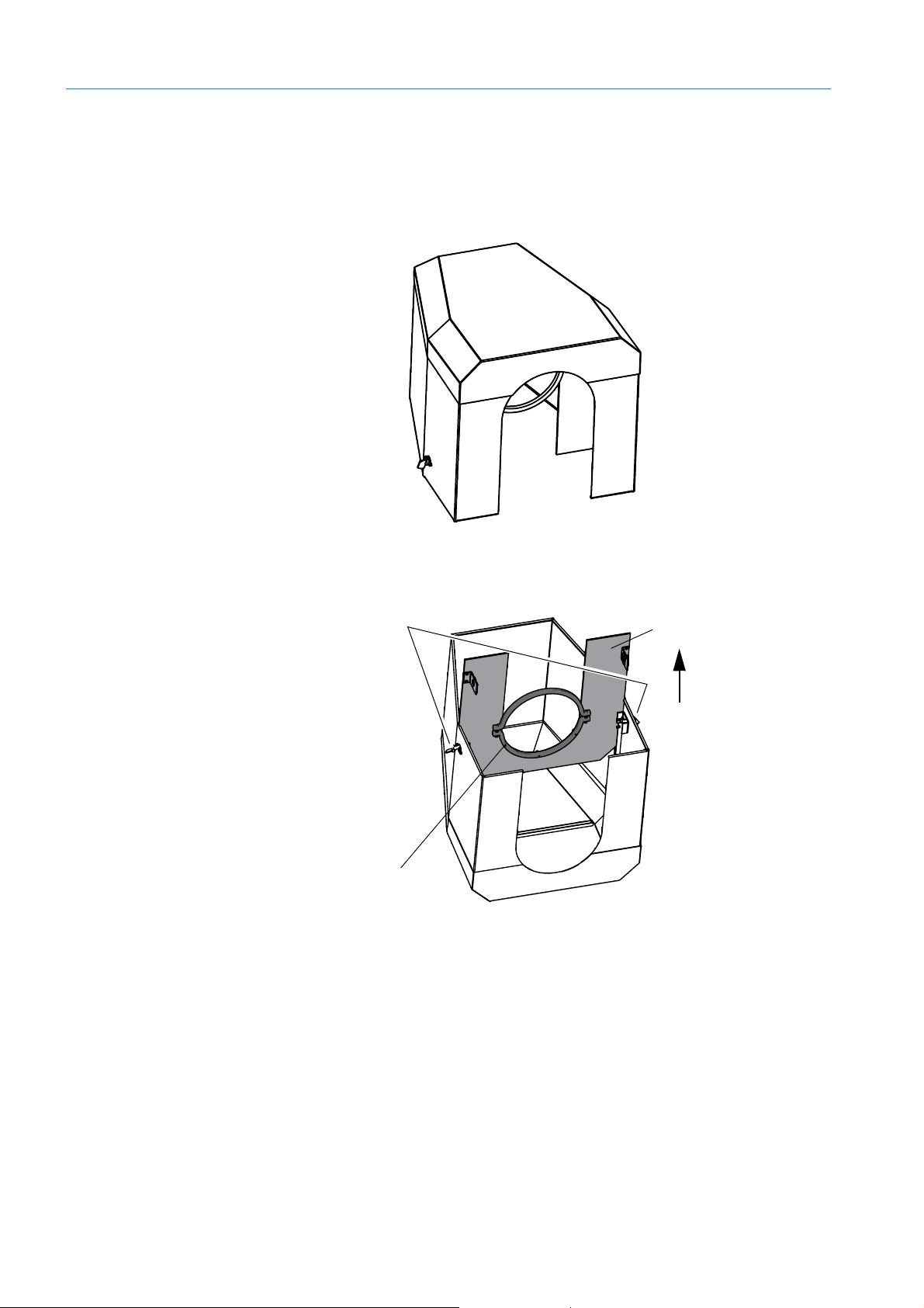
6 START-UP
Lock
Mounting ring
Installation plate
6.3.6 Fitting the weatherproof cover for the SR-unit
The weatherproof cover is used when the measuring system is operated outdoors. It is
available as an accessory.
Fig. 27: Weatherproof cover for the GM700 SR-unit
The weatherproof cover is installed in two steps:
Fig. 28: Weatherproof cover for GM700 SR-unit and reflector unit
1 Installing the installation plate on the flange of the purge air fixture.
▸ Lay the weatherproof cover upside down on the floor.
▸ Open and unhinge the locks on both sides.
▸ Pull the installation plate upwards and remove it from the cover.
2 Installing the cover
54
8010100/YK22/V4-0/2015-12 | SICKOPERATING INSTRUCTIONS | GM700
Subject to change without notice
Page 53
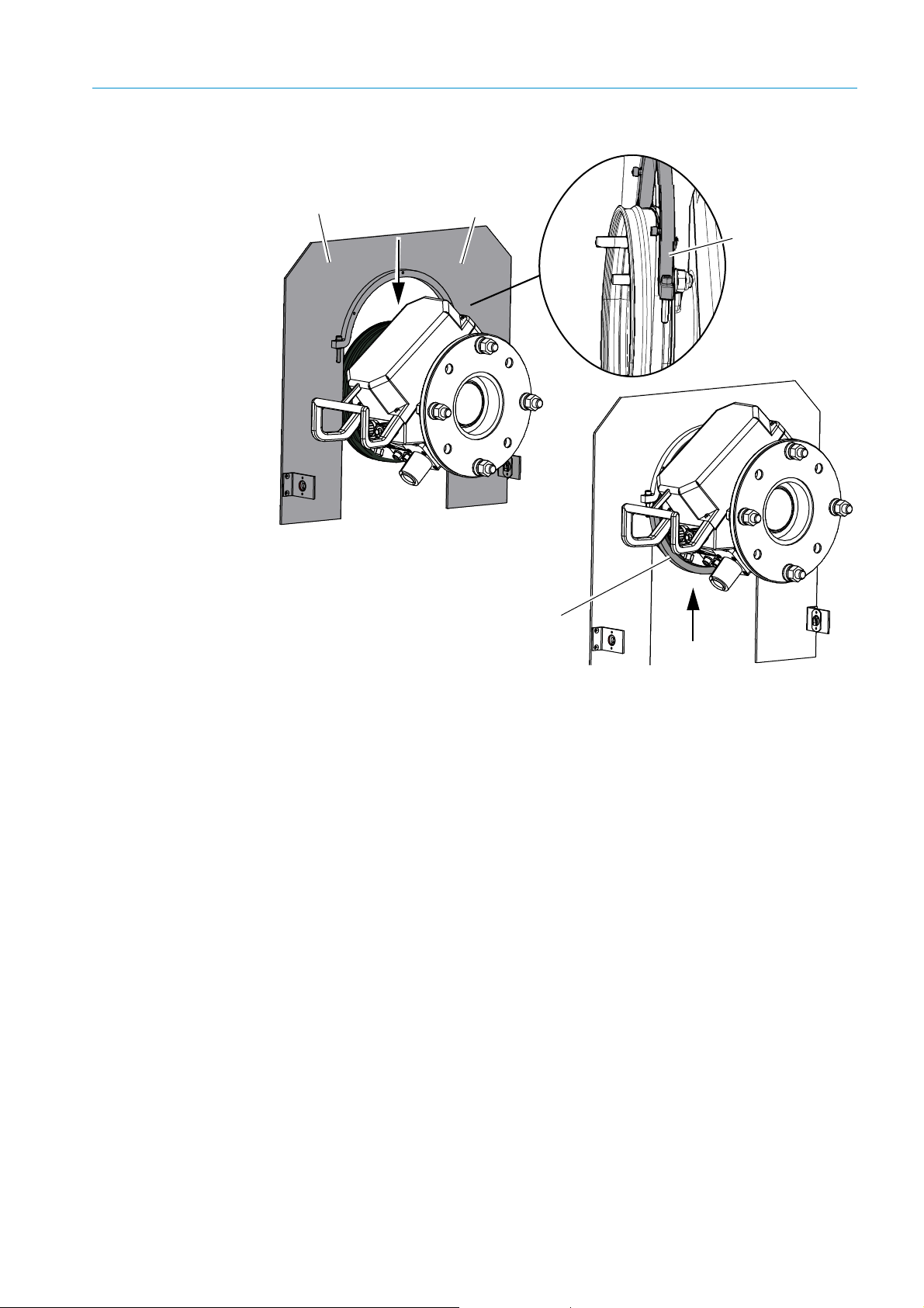
Fig. 29: Installing the cover on the purge air fixture
Upper mounting ring
Installation plate
Lower mounting ring
Detailed view
Position the top
mounting ring on the
side of the purge air
fixture.
(1)
(2)
(3)
START-UP 6
▸ Remove the bottom mounting ring.
▸ Place installation plate (1) from the top on the rubber band of the purge air fixture.
Position the mounting ring on the side of purge air fixture (2); see detailed view in
“Weatherproof cover for the GM700 SR-unit”, page 54.
▸ Fasten bottom mounting ring (3) again.
8010100/YK22/V4-0/2015-12 | SICK OPERATING INSTRUCTIONS | GM700
Subject to change without notice
55
Page 54

6 START-UP
Installation plate
Weatherproof cover
Fig. 30: Fitted weatherproof cover
▸ Place the cover from above on the installation plate.
▸ Click the locks in and close.
6.3.7 Evaluation unit start-up
The evaluation unit is configured with a standard parameter set at the factory and,
therefore, is ready to start measuring operation immediately. With the exception of the
following steps, therefore, no additional measures are required for start-up for standard
applications:
▸ Based on the operator information in “Handling the Evaluation Unit”, page 42, check
whether the measured values are output correctly on the LCD.
If error or warning messages are displayed:
▸ Use the operator information in “Handling the Evaluation Unit”, page 42 as well as the
display of error and warning messages in “Error messages”, page 76 to locate and
rectify the error cause.
If the error cause cannot be rectified with this information, contact the Service department
at SICK or your local sales partner for further advice.
▸ If necessary, parameterize the evaluation unit in accordance with the requirements of
the measuring task and the installation environment “Handling the Evaluation Unit”,
page 42.
56
8010100/YK22/V4-0/2015-12 | SICKOPERATING INSTRUCTIONS | GM700
Subject to change without notice
Page 55

6.3.8 Operating states
1st gas inlet: Zero gas
2nd gas inlet: Test gas
During actual operation, the following operating states can be shown on the evaluation unit
display:
Message in 1st text line Significance
INIT
INITIALISATION
SIGNAL_ADJUST
MEASURING
MEASURING LL
MEASURING LD
MAINTENANCE
DOWNLOAD
Tab le 5 : Operating states
EvU initialization
Initializing the SR-unit
Adjusting amplification to changed transmission
Measuring operation
Measuring mode with active tracking of laser wavelength
(line-locking)
Measuring mode; wavelength tracked (line-locking done)
Maintenance mode (no measurement)
Download new software (for Service purposes only)
6.3.8.1 Gas connections on the GPP measuring probe for zero gas and/or test gas
Depending on the variant, the GM700 analyzer performs independent zero point
measurements in certain intervals to ensure high precision with very small measuring
ranges. A zero gas/test gas connection and a second gas connection for nitrogen purging
or dynamic zeroing directly on the measuring probe are available.
An overpressure is created in the measuring path of the probe during zero or test gas feed.
If this pressure is high enough, the complete sample gas is drained out of the measuring
path because a gas flow runs in the reverse direction through the probe filter. The gas flow
in the filter must be larger than the diffusion velocity of the gases in order to drain out the
sample gas from the measuring path. The analyzer performs the zero point measurements
automatically during measuring operation. They can also be triggered manually with the cal
button on the evaluation unit. “Menu overview”, page 43 and following.
START-UP 6
Fig. 31: Gas inlets on the measuring probe
Equipment
● Gas hoses:
– Teflon hose (PTFE), type 650 P 0707,
– Steel pipe 1.4571,
● Zero gas: Instrument air, class 2
● Pressure reducer
● Supply line
8010100/YK22/V4-0/2015-12 | SICK OPERATING INSTRUCTIONS | GM700
Subject to change without notice
1
/4" with cutting-clamping ring connection (Swagelok)
1
/4"
1
/4"
57
Page 56

6 START-UP
Clamping rings
Gas pipe
(open end)
Cap nut
Inner
bushings
1 Connecting the measuring probe
▸ Connect zero gas (instrument air) to 1st gas inlet “Zero
gas”.
▸ Take off the cap nut from the gas inlet.
▸ Place the cap nut and clamping rings on the open end
of the gas pipe.
▸ Insert the pipe in the open screw fitting.
▸ Tighten the nut with an open end wrench.
▸ Connect zero gas (instrument air) “N
zeroing to 3rd gas inlet as described above.
2 Connecting the instrument air
▸ Connect the pressure reducer to the instrument air supply.
▸ Connect the gas hose from the probe to the pressure regulator outlet.
▸ Set pressure reducer to 250 kPa.
6.3.9 Starting operating mode
On the evaluation unit:
▸ Switch Maintenance mode off:
Mode: Off
Start Measuring mode by pressing the meas button.
The analyzer now starts in Measuring mode.
purging or dyn.
2
When using a gas hose, an inner bushing (Part No. 5309138) must be used to support the
hose and clamping ring.
▸ Check for error or warning messages, especially on the
status LEDs.
▸ If error messages are displayed, clear according to “Error
messages”, page 76.
▸ Set parameters, special times and measuring range, “Handling the Evaluation Unit”, page 42.
58
8010100/YK22/V4-0/2015-12 | SICKOPERATING INSTRUCTIONS | GM700
Subject to change without notice
Page 57

START-UP 6
Selecting the ambient temperature
NOTE: Change of temperature range
The device performs temperature stabilization after a change of the temperature range.
This can take approx. half an hour depending on the environment.
● Warning message “DEV TEMP” is output
▸ Wait for half an hour before performing a zero adjust.
On the evaluation unit:
▸ Select a suitable ambient temperature so that the heater of the SR-unit can stabilize the
optics temperatures.
▸ Activate Parameter mode.
▸ Select menu Settings, then Ambient Temp.
▸ Select the temperature range according the Table below that matches the ambient
conditions at the measuring location.
Possible ambient temperature ranges (test cuvette)
Degrees Celsius [°C] Kelvin [K] Degrees Fahrenheit [°F]
–40 … 10 233 … 283 –40 …50
–30 … 20 243 … 293 –22 … 68
–20 … 30 253 … 303 –4 … 86
–10 … 40 263 … 313 14 … 104
0 … 50 273 … 323 32 … 122
Tab le 6 : Ambient temperature ranges with test cuvette
Possible ambient temperature ranges (closed cuvette)
Degrees Celsius [°C] Kelvin [K] Degrees Fahrenheit [°F]
–40 … 15 233 … 288 –40 … 59
–30 … 25 243 … 298 –22 … 77
–20 … 35 253 … 308 –4 … 95
–10 … 45 263 … 318 14 … 104
0 … 52 273 … 325 32 … 122
Tab le 7 : Ambient temperature ranges with closed test cuvette
The GM700 determines the appropriate temperature for the optics heater automatically.
▸ Zero point adjustment:
NOTE: After changing the temperature range
● Warning message “DEV TEMP” may no longer be shown.
● The temperature change should have been made approx. half an hour ago.
▸ Activate Calibration mode (button “cal”), select menu item Zero Adjust and trigger
with Enter.
▸ Confirm the prompt. Zero point adjustment runs and Zero Measuring is displayed.
8010100/YK22/V4-0/2015-12 | SICK OPERATING INSTRUCTIONS | GM700
Subject to change without notice
59
Page 58

7 MAINTENANCE
7 Maintenance
7.1 Maintenance intervals
The GM700Version with Measuring Probe requires very little maintenance. This Section
describes regular maintenance work to be carried out on the GM700 measuring system.
Qualifications
Inspection and maintenance tasks described in this Section can be carried out by Service
technicians familiar with the device based on the information in these Operating
Instructions and having an in-depth knowledge of the relevant safety regulations.
Maintenance intervals depend on individual application conditions and should be clarified
with SICK Service and/or with a trained engineer or technician at the local sales partner.
If no other specifications have been made, the following recommendation is applicable:
● Maintenance interval – 4 weeks
7.1.1 Maintenance protocol
Keep a log of maintenance work done. A simple notebook recording the maintenance
dates, work done, special observations, and required consumables and spare parts is
adequate.
DANGER: Important safety information for all service work
Always observe the following information when carrying out service work to avoid injury
or damage to the measuring system:
▸ Wear suitable protective clothing and a protective mask when the sample gas is hot
and/or aggressive or has a high dust load, or when the sample gas duct is
pressurized. Never open the enclosure or disengage the quick-release locks without
taking suitable protective measures.
▸ If the conditions in the sample gas duct are particularly problematic and hinder or
prevent work on the open duct, despite the use of protective equipment, the
maintenance work must be carried out when the sample gas duct is out of service or
after it has been flooded with ambient air.
▸ The purge air supply must run continuously.
▸ If visual inspection of the power supply cable reveals damage to the insulation or
strain-relief clamp, switch off the power supply to the cable in question immediately.
7.2 Preparation and general preparatory work
▸ Have the following equipment available for service work:
– At least the following tools: 2 x 24 mm open-end or box wrenches, 1 x 19 mm open-
end or box wrench, Allen key set, insulated screwdriver set for electrical connection
work
– Optical cleaning cloth without detergents, e.g. Part No. 4 003 353
– Distilled water, clean cloths and, if necessary, a dusting brush
– If the duct is pressurized, a suitable protective cover is required for the duct-side
flange with tube.
60
Maintenance tasks for purge air unit→ Purge air unit Operating Instructions.
8010100/YK22/V4-0/2015-12 | SICKOPERATING INSTRUCTIONS | GM700
Subject to change without notice
Page 59

7.3 Maintenance work on SR-unit
7.3.1 Visual inspection and enclosure cleaning
▸ Check the enclosure of the SR-unit for damage such as cracks.
▸ If a weatherproof cover is used, check its condition.
▸ Clean contaminated GM700 system components.
▸ Inspect cables thoroughly for damage and pay particular attention to any signs of
abrasion or bending at cable ducts. Prefabricated cables are available as spare parts.
7.3.2 Cleaning the front window on the SR-unit
WARNING: Take care when the duct is pressurized!
▸ If the duct is pressurized, you must take the appropriate protective measures, in
particular wear a protective mask.
▸ Prepare a suitable cover for the opening on the device flange of the SR-unit and keep
it available.
▸ Fit the cover immediately on the device flange opening after swiveling the SR-unit
open.
CAUTION: Important information for safe handling of the GM700 SR-unit HF
version
For device software versions older than 9105060_YEK0, a higher laser radiation
might occur.
▸ Laser class 1 of the IEC 60825-1:2014-5: Only use device software
9105060_YEK0 or a newer software version.
▸ Never look directly into the exit lens when opening the SR-unit or the reflector.
▸ Always wear laser goggles or switch the device off during maintenance work.
▸ Observe valid national limit values and respective standards for work safety.
MAINTENANCE 7
NOTE: Deviations of EN60825-1:2014-08 “Laser safety” from the Directive
2006/25/EC
Due to the Implemented health and safety regulation for artificial optical radiation
concerning the Directive, deviations of EN60825-1:2014-08 “Laser safety” from
Directive 2006/25/EC have occurred.
▸ Always observe the user information in the Annex of these Operating Instructions!
“User information “Laser safety””, page 97.
▸ Switch the GM700 off.
▸ Open the SR-unit enclosure with a control cabinet key and swivel open.
▸ Check the optical interface (front window) on the SR-unit for contamination and, if
necessary, clean using an optical cleaning cloth. Do not use any detergents because
these leave invisible residues that could falsify the measuring result. The cleaning cloths
can be moistened with distilled water if necessary.
▸ Close and lock the enclosure again to protect the cleaned optical interface against
humidity or dust.
8010100/YK22/V4-0/2015-12 | SICK OPERATING INSTRUCTIONS | GM700
Subject to change without notice
61
Page 60

7 MAINTENANCE
Optical interfaces
(Front window)
Fig. 32:
7.4 Evaluation unit (EvU)
The evaluation unit is designed for maintenance-free operation over the entire service life
of the measuring system. If the evaluation unit is mounted outdoors, the following simple
checks should be carried out regularly due to the load resulting from changing weather
conditions:
▸ Visual inspection
– Is the enclosure undamaged and the fitting intact?
– Does the enclosure front door open and close easily?
– Is the enclosure window free from moisture?
▸ Does the illuminated LC-Display on the evaluation unit function correctly?
▸ Open the evaluation unit door and check the following:
– Are the cable connections OK?
– Is the enclosure dry inside?
▸ If any one of these points is negative, clarify the cause when possible.
▸ Carry out the necessary repairs.
If the evaluation unit is damaged (e.g. LC-Display failure):
▸ Contact SICK Service or the local sales representative.
Exposed electrical connections
The electrical connections are exposed when the evaluation unit door is open.
Follow the relevant safety regulations
62
8010100/YK22/V4-0/2015-12 | SICKOPERATING INSTRUCTIONS | GM700
Subject to change without notice
Page 61

MAINTENANCE 7
7.5 Controlling and tracking the laser working point during measurement
The working point of the laser needs to be tracked when the concentration in the sample
gas is not sufficient. This is done automatically with the help of the fitted reference cell.
7.5.0.1 Selecting the ambient temperature range
NOTE: Change of temperature range
The device performs temperature stabilization after a change of the temperature range.
This can take approx. half an hour depending on the environment.
● Warning message “DEV TEMP“ is output
▸ Wait 30 min. before performing filter box measurement.
On the evaluation unit:
▸ Select the appropriate ambient temperature to allow the heater of the SR-unit to
stabilize the optics temperature.
–Activate Parameter mode
– Select Settings and then the Ambient Temp. menu.
– Select the temperature range according the Table below that matches the ambient
conditions at the measuring location.
Possible ambient temperature ranges (test cuvette)
Degrees Celsius [°C] Kelvin [K] Degrees Fahrenheit [°F]
–40 … 15 233 … 288 –40 … 59
–30 … 25 243 … 298 –22 … 77
–20 … 35 253 … 308 –4 … 95
–10 … 45 263 … 318 14 … 113
0 … 50 273 … 325 32 … 125
Tab le 8 : Possible ambient temperature ranges (test cuvette)
Possible ambient temperature ranges (cuvette filled with gas)
Degrees Celsius [°C] Kelvin [K] Degrees Fahrenheit [°F]
–40 … 15 233 … 288 –40 … 59
–30 … 25 243 … 298 –22 … 77
–20 … 35 253 … 308 –4 … 95
–10 … 45 263 … 318 14 … 113
0 … 52 273 … 325 32 … 125
Tab le 9 : Possible ambient temperature ranges (cuvette filled with gas)
The GM700 analyzer automatically determines the appropriate temperature for the optics
heater.
7.5.1 Filter box measurement to check the measuring channels for NH
The gas filter box serves to check the GM700 with test gases.
Requirements
Components required:
● Reflector enclosure with gold-plated hollow triple reflector;
Part No. 2030206
● Filter box with adapter plate for the GM700
, HF or HCl
3
8010100/YK22/V4-0/2015-12 | SICK OPERATING INSTRUCTIONS | GM700
Subject to change without notice
63
Page 62

7 MAINTENANCE
Adapter plate for GM700
Reflector enclosure
Fig. 33: Components required: Filter box for GM700
Measured values are displayed on the EvU in mg/m3 • m (operation).
64
8010100/YK22/V4-0/2015-12 | SICKOPERATING INSTRUCTIONS | GM700
Subject to change without notice
Page 63

7.5.2 Determining the necessary test gas concentration
Test gas conc. [ppm or % by vol.]
Meas. range [ppm or % by vol.] act. meas. path [m]
•
0.15 m max. filter chamber length
-----------------------------------------------------------------------------------------------------------------
=
CO
Tetarg
Test gas conc. [ppm] 0.758
273
353
----------
••
act. air pressure [hPa]
1013
--------------------------------------------------------
• L [mm]
Chamber
• 0.001•=
Conversion factor depends on the component
NH3: 0.758, HF: 0.892, HCl: 1.628
Intermediate housing
Bolt
1 General calculation:
2 Calculating setpoint values for all 6 chamber lengths:
Comp. Required test gas concentration
Filter chamber lengths
25 mm 50 mm 75 mm 100 mm 125 mm 150 mm
NH
3
HF
HCl
Table 10: Test gas concentrations for the respective filter chamber lengths
MAINTENANCE 7
7.5.3 Installing the filter box
Fig. 34: Filter box
▸ Swivel the intermediate GM700 enclosure open, remove the bolts and take off the
intermediate enclosure. Store safely until filter box measurement is completed.
8010100/YK22/V4-0/2015-12 | SICK OPERATING INSTRUCTIONS | GM700
Subject to change without notice
65
Page 64

7 MAINTENANCE
Bolt
SR-unit
Filter box
Reflector
Fig. 35: Installing the filter box on the GM700
▸ Position the filter box with adapter plate on the SR-unit:
▸ Insert the filter box in the SR-unit hinge
▸ Insert and fasten the bolt
▸ Swivel the filter box on the SR-unit in and lock with the locking device
▸ Fit the reflector for GM700 on the filter box.
Fig. 36: Installing the filter box on the measuring device
7.5.4 Carry out filter box measurement
▸ Switch the filter box on; the warm-up phase takes about 2.5 hours.
▸ Switch on the zero gas pump or connect a different zero gas.
▸ Switch all chamber valves to “Zero gas” and the Measure/Purge valve to “Purge”.
66
8010100/YK22/V4-0/2015-12 | SICKOPERATING INSTRUCTIONS | GM700
Subject to change without notice
Page 65

MAINTENANCE 7
ON/OFF switch
Power supply
connection
Test ga s val ve to s witc h
individual measuring
chambers
Purge valve
Zero gas valve
Zero gas
connection
Gas connection,
measuring
chamber 75 mm
Gas connection,
measuring
chamber 50 mm
Gas connection,
measuring
chamber 25 mm
Pump ON/OFF
switch
Temperature displays, preheater and measuring chamber
On the EvU:
▸ After about 3 minutes, call Box measuring in menu cal (button cal) and select the option
“gas”.
▸ Enter password “1 2 3 4”.
▸ The measuring device now starts a zero adjust and then switches to operating mode
“Box measuring”.
Fig. 37: Control elements on the filter box
8010100/YK22/V4-0/2015-12 | SICK OPERATING INSTRUCTIONS | GM700
Subject to change without notice
▸ Connect test gas; set the primary pressure to approx. 1000 hPa (1 bar).
▸ Note the diameters of individual chambers and/or chamber combinations of the filter
box and the concentration values; see Section 9.6.1, page 96.
▸ At the same time, set the respective filter chambers to “Test gas”.
▸ Switch the Measuring/Purging valve to “Purging” for 2 to 3 minutes (until the
measured value has stabilized) and then to “Measuring”.
▸ The overpressure from the purge phase now dissipates.
▸ When the measured value has stabilized again, read off and note the value.
Restart measuring mode
▸ Purge the filter box with zero gas.
On the EvU:
▸ Exit operating mode “Box measuring” by pressing back.
▸ Disassemble the filter box with plate and reflector from the SR-unit and store safely.
▸ Refit the SR-unit back onto the sampling point in the correct position.
67
Page 66

7 MAINTENANCE
Nominal value
Test cell
Test value
1000 mm
150 mm
---------------------------------
• 5 mg/m
3 1000 mm
150 mm
---------------------------------
• 33.3 mg/m
3
===
Output
Device
Test value
273°C
273°C Temp
Cell
+
---------------------------------------------------------------
• 5 mg/m
3 273°C
393°C
-----------------------
• 3.47 mg/m
3
===
Test value Output
Device
273°C Temp
Cell
+
273°C
---------------------------------------------------------------
• 3.47 mg/m
3 393°C
273°C
-----------------------
• 5 mg/m
3
===
7.6 Checking the gas analyzer with test cell GMK10
Special characteristics of a measuring component or also the availability of test gases with
the precision required for reference materials require the generation of the span gas from
aqueous solutions with known content. This is the standard case for GM700-2 (HF).
A test gas system with hose pump, scales and evaporator is required in addition to the
heated test cell GMK10 (example: Hovacal).
Requirements
WARNING: Aggressive and corrosive gases
All materials used must be suitable for the measuring components, e.g. HCl, HF.
The manufacturer recommends to exclusively use the evaporator of the test gas
system for this check.
Components required:
● Zero path; Part No. 46483
● Test cell GMK10 with heated sample gas line
● Settings of the test gas system (Hovacal)
Consider the following when entering the nominal value of the concentration (mg/m
− Test cell length of 150 mm
− Test gas temperature depending on setting (120 ...
140 °C)
− Measured value output in mg/m
state relative to an active measuring path length of
1 m (1000 mm)
Input nominal value (in standard state; 0 °C, 1013 hPa) in test gas system (Hovacal):
Example: Test value = 5 mg/m
3
3
in the operating
3
):
The values are displayed in mg/m3 (operation):
Comparison of actual display with entered nominal value:
● Aqueous solution of test component (e.g. 0.01 M for HF)
● Distilled water
● Nitrogen 4.6 or better (compressed gas cylinder)
● Length of hose for safe discharge of the test gas
● Measurement of ambient air pressure
68
8010100/YK22/V4-0/2015-12 | SICKOPERATING INSTRUCTIONS | GM700
Subject to change without notice
Page 67

On the evaluation unit:
GM700 SR-unit
GMK10 test cell
Zero path
Power supply
Gas outlet
Sample gas connection
Set the measuring system to maintenance mode before removing the device from the
sampling point.
On the evaluation unit:
Press button “maint”
Select “Maintenance Mode” and activate maintenance operation
7.6.1 Installation of the GM700 components with the test cell GMK10
Fig. 38: Assembly of the GM700 components and the test cell
MAINTENANCE 7
Remove the SR-unit and the measuring probe from the sampling point.
Use the 4 M16 screws to fit the GMK10 with device flange to the measuring probe.
Installation of GM700 components “Fitting system components”, page 35.
Perform connections on the GMK10:
Connect the cables for energy supply.
Connect the sample gas line
Connect the hose for gas discharge from the test gas system to the gas outlet
Prepare the test gas system and put it into operation. Refer to separate Operating
Instructions etc. of the test gas system.
Fig. 39: Connections of the GMK10 test cell
8010100/YK22/V4-0/2015-12 | SICK OPERATING INSTRUCTIONS | GM700
Subject to change without notice
69
Page 68

7 MAINTENANCE
7.6.2 Carrying out measurement
Step 1: Checking optical alignment
– The CAN line from the SR-unit to the purge air fixture may not be connected, the
system switches to using the default values for pressure and temperature.
If necessary, disconnect this CAN line. Connect the remaining connections of the
measuring system, “Electrical connections on the sender/receiver unit”, page 49.
Connect the cable for power supply to the GMK10.
Connect the sample gas line from the test gas system.
If necessary, connect the power supply for all GM700 components
Step 2: Settings:
As standard, the temperature of the test cell and the heated sample gas line is
120 °C. Temperatures up to 140°C are possible depending on the application.
Check the temperature on the GMK10.
– Check the temperature indicator on the GMK10 cover.
– Set the desired temperature accordingly when the indicator does not show 120 °C:
– Remove the cover of the GMK10 and set the temperature on the temperature
controller. If required, see separate Operating Instructions of the temperature
controller.
Checking optical alignment → “Zero adjust”, page 52.
CAUTION:
It is possible to perform the check of the GM700 with a separate reflector on a zero
tube or a similar construction.
Independent therefrom, the optical alignment is always performed to the probe
position (marking "O, circle" on the target).
WARNING: Hazard by dangerous laser radiation
When the device is operated without probe, dangerous exposure to radiation may
occur.
▸ Always close the reflector when the device is operated without measuring probe.
70
8010100/YK22/V4-0/2015-12 | SICKOPERATING INSTRUCTIONS | GM700
Subject to change without notice
Page 69

Fig. 40: Temperature indicator on GMK10
Temperature indicator
Temperature controller
MAINTENANCE 7
On the EvU: Enter the temperature chosen for the test cell, e.g. 120 °C, as default
value and enter 1013 hPa as default value for pressure.
Step 3: Set the evaporator temperature on the test gas generator to 180 °C. The test cell is
purged with nitrogen during the warming up phase.
Warming up time: Approx. one hour
Measurement can begin after a warming up time of at least one hour. However, we
recommend to first purge the system by evaporating pure water.
NOTE: Software version UD81 or higher
Software version UD81 or higher must be installed in the GM700 measuring system for
this procedure!
See Section “Menu overview”, page 43 →p. 45, 5.2.1
Step 4: Perform measurement:
When stable conditions exist − to be seen by the trend of the measured values −
activate boxmeasuring mode on the GM700 EvU
– On the EvU: Call up menu cal with the cal button, activate
with
Enter.
– Enter password
“1 2 3 4”.
“Boxmeasuring” and start
The measuring device now starts a zero adjust and then switches to operating mode
“Box measuring”. As for each filter box measurement, the system first performs a
temporary zero adjust and then changes to boxmeasuring mode. The output of the
measured values is performed analog to standard filter box measurement in mg/m
3
(during operation, relative to 1 m active measuring path).
8010100/YK22/V4-0/2015-12 | SICK OPERATING INSTRUCTIONS | GM700
Subject to change without notice
71
Page 70

7 MAINTENANCE
Since the setpoint setting at the test gas system (Hovacal) is "standard", correct the
value comparison (ambient) pressure and (test cell) temperature.
Recommendation
● To prevent pressure build-up in the measuring cell, do not use higher flow
rates than
● Pay attention to the unhindered discharge of the sample gas at the gas
4 l/min. for the measurements.
outlet.
● The standard solution used for the test must be chosen so that the H
concentration of the generated test gas does not exceed 30% by volume
at any test point. Typical value for HF: 0.01M.
Step 5: Terminate the measurement
After termination of boxmeasuring mode (“
back“ button), the conditions for normal
measuring mode are reestablished, e.g. indication of measured value as parameterized.
Terminate the measurement with the “back” button.
Reinstall the GM700 SR and reflector unit to the purge air fixtures at the sampling
point and continue Measuring mode.
NOTE: Purge the measuring system with evaporated distilled water
After the end of the measurements, the system must be purged with vaporized
distilled water until the zero point is reached again!
Before switching off the heaters, the system must be purged with dry nitrogen for a
minimum of 5 minutes.
Make gas connections.
O
2
72
8010100/YK22/V4-0/2015-12 | SICKOPERATING INSTRUCTIONS | GM700
Subject to change without notice
Page 71

TROUBLESHOOTING AND CLEARING MALFUNCTIONS 8
maintcalpardiag
GM 35
Evaluation Unit
CO
CO
2
H2O
mg/
m
3
236
Ref. conditions
Hum: wet
Measuring
Operation
Service
Warnin
Malfunction
8 Troubleshooting and Clearing Malfunctions
8.1 Malfunction categories/possible effects
This Section shows how malfunctions of the GM700 can be recognized, diagnosed and
cleared. It is primarily aimed at the operating personnel responsible for the current
operation of the measuring system as well as maintenance technicians responsible for
clearing malfunctions.
GM700 malfunctions are categorized according to the anticipated effects.
Damage to the measuring system itself
Depending on the installation conditions and measuring system version, a purge air failure
could cause damage to the GM700 .
8.2 Purge air failure
Failure of the purge air supply demands measures to be taken immediately or within a
short time, depending on the installation conditions, to protect the measuring system. A
purge air failure, however, rarely occurs in practice. It is still however wise to be prepared
for such an occurrence to prevent damage to the measuring system.
Indications of a potential purge air failure
● Error message on systems that are equipped with a pressure difference sensor
● Purge air unit power supply failure
● Increase in enclosure temperature of the GM700 SR-unit
● Rapid increase in contamination on optical interfaces of the SR-unit
● Hose for the purge air supply to the purge air fixture is loose or visibly damaged
Tools for troubleshooting
● Suitable protective equipment (protective clothing, gloves, etc.) that enable the gas duct
to be opened safely and the SR-unit as well as the reflector removed under the given
installation conditions (hot/aggressive/noxious/dust-laden sample gases, overpressure
in the duct).
● 2 wrenches to remove the SR-unit and reflector and, possibly, other tools required to
restore the power supply.
● Flange cover to seal off the flange opening when the measuring system is removed.
8.3 Integrated monitoring and diagnosis system
The GM700 is equipped with an integrated system that
constantly monitors the operating state of the SR-unit and
evaluation unit. Appropriate messages are generated and
logged in the devices for subsequent evaluation should any
deviations from normal operating conditions occur.
Depending on the anticipated effects, the messages of the
system components are categorized into error messages and
warning messages: Warning messages are generated if the
measurement results are not (yet) directly affected by the
change in the system state. Nevertheless, it is important that
the cause(s) be investigated and corrected, e.g. by means of
maintenance measures, to avoid further malfunctions and
damage to the device in particular.
8010100/YK22/V4-0/2015-12 | SICK OPERATING INSTRUCTIONS | GM700
Subject to change without notice
73
Page 72

8 TROUBLESHOOTING AND CLEARING MALFUNCTIONS
Error messages are generated when measuring operation is no longer possible or no
longer reliable. These warning and error messages are stored in the integrated message
memory of the evaluation unit.
8.3.1 Display and retrieval of messages on the evaluation unit
Component/Tool Signals Note
Operation
Service
Warning
Malfunction
Diagnosis mode
Functional impairment on system
Warning LED goes on
Front panel
Evaluation unit
Malfunction LED blinks
Error Storage Table Call menu Malfunction
Warning Storage Table Call menu Warning
Output
for serious problems
(malfunction, error
message)
[1]The relay is active during normal operation (no malfunctions), i.e. the contact is closed.
Relay 1 inactive
[1]
that will not directly lead to corrupt
measured values.
Functional impairment on system
that can lead to system failure or
restricted function.
Plain-text message(s) for errors that
have occurred to localize and clear
the problem.
See “Troubleshooting Table”.
Plain-text message(s) for pending
warnings
Group malfunction
Troubleshooting Table
If a warning or malfunction is signaled, first call up pending error messages in the Error
menu. Then localize the possible cause and clear the malfunction; see Troubleshooting
Tab le.
Error indication Possible causes Clearance
● LED Malfunction blinks;
(
LED Warning could go on)
● Relay 1:
Group malfunction
74
Plain-text error messages
indicate possible causes
Tab le 1 1: Troubleshooting Table
▸ Start Diagnosis mode (diag):
–Call menu
– Check and clear the specified malfunction.
Malfunction (and/or Warning)
8010100/YK22/V4-0/2015-12 | SICKOPERATING INSTRUCTIONS | GM700
Subject to change without notice
Page 73

TROUBLESHOOTING AND CLEARING MALFUNCTIONS 8
Jumpers:
Open: 230 V AC
Plugged: 115 V
Fuses:
2.5 AT, 250 V
Screw terminals (CAN)
for SR-unit
Display for 24/5 V
8.3.2 Troubleshooting and clearing malfunctions, evaluation unit
Evaluation unit not responding
Evaluation unit:
● Evaluation unit power supply
defective
Evaluation unit:
● Incorrect operating voltage
Evaluation unit:
● Defective fuse
Evaluation unit:
● No defect localized yet
Evaluation unit:
● Error occurs again
Evaluation unit:
● 24V/5V supply defective
Evaluation unit:
● Inconsistent data detected in
parameter memory
▸ Check power supply on all system components:
– If necessary, provide power supply on site
– If necessary, check/reconnect connections on the
system components
▸ Check operating voltage set on the evaluation unit:
– If necessary, change setting
▸ Check fuse in the evaluation unit:
– If necessary, replace fuse
▸ Disconnect all system components from the power supply
and reconnect one at a time
– Check the CAN bus cable from the evaluation unit to
the SR-unit and/or terminal box
▸ Replace the last component connected, contact Service
▸ Check 24V/5V supply, replace
evaluation unit and/or electronic board module; contact
Service
▸ Press Enter to restart the system; the factory parameter
settings are then active;
▸ If necessary, reconfigure the parameters
▸ If the same error message occurs again, replace the EvU
and contact Service.
Fuses
▸ Open the EvU enclosure
▸ Check fuses and replace when necessary
Power supply
▸ Check the indicator for the 24 V/5V supply and, if
necessary, remove the screw terminal (CAN) of the signal
cable to the SR-unit.
▸ If these indicators only light up when the connector has
been removed, check the cabling first.
▸ If no error is found, connect the system components one
by one
– Only connect the cable between the EvU and SR-unit
– Connect the cable to the reflector
Table 12: Troubleshooting and clearing malfunctions, evaluation unit
8010100/YK22/V4-0/2015-12 | SICK OPERATING INSTRUCTIONS | GM700
Subject to change without notice
75
Page 74

8 TROUBLESHOOTING AND CLEARING MALFUNCTIONS
8.3.3 Error messages
Error message Component/possible causes Clearance
Air purge low SLV
CD: Filter watch SLV
CD: P No Signal SLV
CD: P out of range SLV
CD: T Air Sign. SLV
CD: [t] No Signal SLV
CDOH: No communication
SLV
CDR: No communication
SLV
DSP: BOOT ERROR
DSP…Digital Signal
Processor
DSP: INV PARA
DSP: NO RESP
EEPROM: CONTROL
EEPROM: LASER
FIT: DIV BY 0
FIT: NO CONV
FIT: S MATRIX
Tab le 1 3: Error messages
The volume flow is below the set limit.
Low-pressure monitor of purge air unit
switches on binary input
No signal from pressure sensor
Sample gas pressure < 500 or
>1200hPa/mbar
Broken sensor and/or no temperature
sensor (purge air temperature)
connected
Broken sensor and/or no temperature
sensor (exhaust gas temperature)
connected
CAN connection EvU – purge air fixture
SR interrupted
CAN connection EvU – purge air fixture
reflector interrupted
Error during start process
Incompatible software (SR-unit)
Invalid values entered
Electronics communication problem
(SR-unit)
Invalid microcontroller parameters (SRunit)
Invalid laser parameters
Error during signal evaluation:
● Incorrect parameter values
● Hardware defective
Error during signal evaluation:
● Incorrect parameter values
● Hardware defective
Error during signal evaluation:
● Incorrect parameter values
● Hardware defective
▸ Check the purge air supply (blower, hoses), if
necessary, exchange filter on purge air blower,
→ Purge air unit Operating Instructions.
▸ Check the purge air supply (blower, hoses), if
necessary, exchange filter on purge air blower,
→ Purge air unit Operating Instructions.
▸ Check connection and cable connection of pressure
sensor on purge air fixture and repair if necessary
▸ Check and/or replace pressure sensor
▸ Check connection and cable connection of
temperature sensor (purge air temperature) on
purge air fixture and repair if necessary
▸ Check connection and cable connection of
temperature sensor (exhaust gas temperature) on
purge air fixture and repair if necessary
▸ Check CAN connection; disconnect and reconnect
plug, repair if necessary
▸ Check CAN connection; disconnect and reconnect
plug, repair if necessary
▸ Restart device
–Press maint button to activate maintenance
–Trigger menu
– switch device off and on again
▸ If not successful, contact Service
▸ Check software version, contact Service if
necessary
▸ Correct erroneous values
▸ Restart device, see above
▸ If not successful, contact Service
▸ Restart device, see above
▸ If not successful, contact Service
▸ Restart device, see above
▸ If not successful, contact Service
▸ Check parameters measuring distance,
substitute for temperature and pressure and
correct if necessary
▸ Restart device, see above
▸ If not successful, contact Service
▸ Check parameters measuring distance,
substitute for temperature and pressure
▸ Increase parameter Average
Attention: Only by trained personnel!
▸ Restart device, see above
▸ If not successful, contact Service
▸ Check parameters measuring distance,
substitute for temperature and pressure and
correct if necessary
▸ Restart device, see above
▸ If not successful, contact Service
Reset System or
76
8010100/YK22/V4-0/2015-12 | SICKOPERATING INSTRUCTIONS | GM700
Subject to change without notice
Page 75

TROUBLESHOOTING AND CLEARING MALFUNCTIONS 8
Error message Component/possible causes Clearance
Incompatible device
INIT: NO LINE
LD: PELT ERROR
LD…laser diode
LD: TEMP ERROR
MEAS: M PLAUS
MEAS: R PLAUS
MEAS: REF CONC
(only for devices with
closed cuvette)
Sensor communication
SIG: DARK VALUE
SIG: K HIGH
SIG: K LOW
SIG: M HIGH
SIG: M LOW
SIG: R HIGH
SIG: R LOW
Z MEAS: RANGE
(only for devices with NH3
measurement)
Table 13: Error messages
Incompatible software (SR-unit)
No absorption line found
Temperature measurement on Peltier
element defective:
● Possible hardware defect
Laser wavelength adjustment outside
allowed range
● Absorption line “lost”
● Laser diode defective
Measuring results from measuring
channel not plausible:
● Incorrect parameter values
● Strong signal interference
● Hardware defect
Measuring results from measuring
channel not plausible:
● Incorrect parameter values
● Strong signal interference
● Hardware defect
Gas concentration in reference cuvette
too low
SR-unit not connected correctly ▸ Check CAN connection and repair if necessary
Dark values of receiver element too
high:
● Possible hardware defect
Monitoring channel signal too high ▸ Contact Service
Monitoring channel signal too low ▸ Contact Service
Measuring channel signal too high ▸ Contact Service
Measuring channel signal too low:
● Optical interfaces (front window) of
SR-unit or reflector contaminated
● Optical axes alignment too
inaccurate
● Hardware defect
Reference channel signal too high ▸ Contact Service
Reference channel signal too low ▸ Contact Service
Unallowed results during zero gas
measurement:
● Zero gas missing
● Optical interfaces (front window) of
SR-unit or reflector contaminated
● Optical axes alignment too
inaccurate
▸ Check software version
▸ Contact Service
▸ Restart device, see above
▸ If not successful, contact Service
▸ Restart device, see above
▸ If not successful, contact Service
▸ Restart device, see above
▸ If not successful, contact Service
▸ Check parameters measuring path, substitute
for
temperature and pressure
▸ Increase parameter Average
Attention: Only by trained personnel!
▸ Restart device, see above
▸ If not successful, contact Service
▸ Restart device, see above
▸ If not successful, contact Service
▸ Exchange reference cuvette
▸ Contact Service
▸ Contact Service
▸ Clean front window, “Cleaning the front window on the
SR-unit”, page 61.
▸ Check optical alignment and correct if necessary,
→
“Optical alignment”, page 50.
▸ If not successful, contact Service
▸ Check zero gas supply and repair if necessary
▸ Clean front window, “Cleaning the front window on the
SR-unit”, page 61
▸ Check optical alignment and correct if necessary,
“Optical alignment”, page 50.
8010100/YK22/V4-0/2015-12 | SICK OPERATING INSTRUCTIONS | GM700
Subject to change without notice
77
Page 76

8 TROUBLESHOOTING AND CLEARING MALFUNCTIONS
8.3.4 Warning messages
Warning message Component/possible causes Clearance
Feed Test Gas
FIT: LINEPOS
H2O Undef.
(only for GM700-8)
MEAS: REF CONC
(only for devices with closed
cuvette)
DEV: TEMP
No detectable sample gas
concentration (see Interval)
Deviation of absorption line
position:
● Line not adjusted perfectly dur-
ing start process
Monitoring measurability of H2O:
● This warning appears when the
gas temperature drops below
the switch threshold set
Gas concentration in reference
cuvette too low; measurement still
possible
Optic of SR-unit out of allowed
temperature range:
● Warm-up phase after switching
on
● Ambient temperature too high
Tab le 1 4: Warning messages
▸ Feed test gas
▸ Wait until the warning message disappears after a few
minutes
▸ Restart device
– Activate Maintenance mode with maint button
– Trigger menu item Reset System or
– switch device off and on again
– If not successful, contact Service
“---” appears on the EvU display. This signals that no value
is available. The warning message disappears again as
soon as the temperature exceeds the switch threshold
▸ Plan and prepare reference cuvette replacement
▸ Wait until the temperature has stabilized
▸ Select different ambient temperature range, “Selecting
the ambient temperature range”, page 63.
▸ Cool device
78
8010100/YK22/V4-0/2015-12 | SICKOPERATING INSTRUCTIONS | GM700
Subject to change without notice
Page 77

8.3.5 Further tips on troubleshooting
Fuses
2.5 AT, 250 V
Operating voltage:
230 V AC – no jumper
115 V AC – jumper
5 V DC
LEDs light up:
Internal voltage supply
present
24 V DC
LEDs light up when inputs
are connected, i.e. a signal
is pending
Digital inputs,
2 and 3
Analog
output
Relay
outputs
1...4
Fig. 41: Troubleshooting on the evaluation unit: LED displays, signals and fuses
TROUBLESHOOTING AND CLEARING MALFUNCTIONS 8
Evaluation unit not responding
▸ Check the power supply on the GM700, check the operating voltage set
▸ Check the fuse in the evaluation unit; check the 24 V/5 V supply indicator in the
evaluation unit, when doing so, remove the plug-in terminal on the cable to the receiver.
▸ If these indicators only light up when the plug-in connector has been removed, check the
cabling first.
Communication fault between evaluation unit and GM700 SR-unit
Error message:
Check following connections:
Sensor Communication???
▸ Connection between evaluation unit and SR-unit.
▸ Cable connection on the plug-in terminal in the evaluation unit.
▸ Cable to SR-unit.
▸ Outer plug-in connectors on SR-unit.
▸ Inner plug-in connectors in SR-unit.
8010100/YK22/V4-0/2015-12 | SICK OPERATING INSTRUCTIONS | GM700
Subject to change without notice
79
Page 78

9 TECHNICAL DATA, EXPENDABLE AND SPARE PARTS
9 Technical Data, Expendable and Spare Parts
9.1 Technical data GM700 probe system
Combination of measuring components
Minimum and maximum measuring range end values are only applicable for single
components. Extremely small or large end values for different components cannot be
combined in all cases.
Measured data GM700 system
Measured variables NH
Performance-tested measured
variables
Measuring principle Diode laser spectroscopy (TDLS)
Measuring path length
Measuring ranges
NH
HF 0 ... 5 ppm / 0 ... 2,000 ppm
HCl 0 ... 10 ppm / 0 ... 3,000 ppm
Dual measuring ranges
HCI / H
NH
O 0 ... 10 ppm / 0 ... 3,000 ppm (HCI)
2
/ H2O 0 ... 25 ppm / 0 ... 4,000 ppm (NH3)
3
Response time 1 s ... 360 s
Accuracy
Zero point
Sensitivity
Process temperature
Ambient temperature
Storage temperature –40 °C … +55 °C
Ambient humidity ≤ 85% relative humidity; non-condensing
Tab le 1 5: Technical data GM700 system
HF, HCl, H2O
3,
HF
● Open measuring probe (GMP): 0.25 mm ... 1.5 m,
depending on application
● Gas-testable measuring probe (GPP): 0.227 m ... 0.977 m,
depending on application
0 ... 25 ppm / 0 ... 4,000 ppm
3
Measuring ranges refer to 1 m measuring path
Measuring ranges depend on the application and device
version
0 ... 50 vol-% / 0 ... 100 vol-% (H
0 ... 5 vol-% / 0 ... 40 vol-% (H
Measuring ranges refer to 1 m measuring path
Measuring ranges depend on the application and device
version
≤± 2 %, relative to full scale value
≤± 2 %, in maintenance interval (6 months), relative to full
scale value
● GMP: –40 °C ... +250 °C
● GMP: –40 °C ... +430 °C
Depending on device version
–40 °C … +50 °C; depending on parameter settings;
temperature change max. ± 10 °C/h
O)
2
O)
2
80
8010100/YK22/V4-0/2015-12 | SICKOPERATING INSTRUCTIONS | GM700
Subject to change without notice
Page 79

TECHNICAL DATA, EXPENDABLE AND SPARE PARTS 9
EN 61010-1
EN 15267
EN 14181
Compliances
Electrical safety CE
Control functions Automatic check cycle for zero and reference point
Table 15: Technical data GM700 system
Sender/receiver unit
Description Analyzer unit of the measuring system
Degree of protection IP 65
Dimensions (W x H x D) 239 mm x 272 mm x 330 mm
Weight 13 kg
Power supply
Voltage Supply via the evaluation unit: 24 V DC
Auxiliary gas connections
Table 16: Technical data sender/receiver unit
EN 60825-1:2014-8
EN 61326-1
2000/76/EC (17. BlmSchV)
27. BlmSchV
(only for
NH
3
and
HCl)
Test gas: Swagelok 1/4″
Purge gas: Swagelok 1/4″
Open measuring probe (GMP)
Description
Process temperature –40 °C ... +250 °C
Process pressure Depending on purge air supply
Process gas humidity Non-condensing
Degree of protection IP 65
Dimensions (W x H x D) See dimension drawings
Weight 25 kg
Power supply
Voltage Supply via the evaluation unit: 24 V DC
Built-in components
Table 17: Technical data GMP measuring probe
Measuring probe in open design version with integrated purge
air guidance system
● Flow monitor (to monitor the purge air supply)
● Temperature sensor PT1000 (to measure the gas
temperature)
● Pressure sensor
Gas-testable measuring probe (GPP)
Description
Process temperature
Process pressure 120 hPa
Degree of protection IP 65
Dimensions (W x H x D) See dimension drawings
Weight 45 kg
Table 18: Technical data GPP measuring probe
Measuring probe with gas permeable filter element for
adjustment with test gas
● HCl: +130 °C ... +430 °C
● NH3: +300 °C ... +430 °C
8010100/YK22/V4-0/2015-12 | SICK OPERATING INSTRUCTIONS | GM700
Subject to change without notice
81
Page 80

9 TECHNICAL DATA, EXPENDABLE AND SPARE PARTS
Power supply
Voltage 150 V / 230 V
Frequency 50 Hz / 60 Hz
Power input
Built-in components
Tab le 1 8: Technical data GPP measuring probe
GM700 evaluation unit: Sheet steel enclosure
Description
Degree of protection IP 65 / NEMA 4x
Analog outputs 3 outputs:
Analog inputs 2 inputs:
Digital outputs
Digital inputs 3 inputs: 24 V
Interfaces and bus protocols
RS-232 Proprietary (service interface)
Display
Input
Design Sheet steel enclosure
Dimensions (W x H x D) 200 mm x 346 mm x 97.5 mm)
Weight ≤ 4.7 kg kg
Power supply
Voltage 115 V / 230 V
Frequency 50 Hz / 60 Hz
Power input ≤ 50 W
Tab le 1 9: Technical data GM700 evaluation unit: Sheet steel enclosure
≤ 150 W
● Temperature sensor PT1000 (to measure the gas
temperature)
● Pressure sensor
● Heating the optical interfaces
The evaluation unit serves as user interface, for data processing
and output as well as control and monitoring functions
0/4 ... 20 mA, 500 Ω,
Electrically isolated
0 ... 20 mA, 100 Ω,
For gas temperature and gas pressure
3 relay contacts:
● 48 V AC
● 1 A, 60 W / 48 V DC
● 1 A, 30 W
● LC-Display
● Status LEDs: “Operation”, “Warning” and “Malfunction”
● Arrow keys
● Function buttons
82
GM700 evaluation unit: Cast metal enclosure
Description
Degree of protection IP 67 /NEMA 6
Analog outputs 3 outputs:
Tab le 2 0: Technical data GM700 evaluation unit: Cast metal enclosure
The evaluation unit serves as user interface, for data processing
and output as well as control and monitoring function
0/4 ... 20 mA, 500 Ω,
Electrically isolated
8010100/YK22/V4-0/2015-12 | SICKOPERATING INSTRUCTIONS | GM700
Subject to change without notice
Page 81

TECHNICAL DATA, EXPENDABLE AND SPARE PARTS 9
Analog inputs 2 inputs:
0 ... 20 mA, 100 Ω,
For gas temperature and gas pressure
3 relay contacts:
Digital outputs
Digital inputs
Interfaces and bus protocols
RS-232 Proprietary (service interface)
Display
Input
Design Cast metal enclosure
Dimensions (W x H x D) 289 mm x 370 mm x 138 mm
Weight ≤ 8.6 kg
Power supply
Voltage 115 V / 230 V
Frequency 50 Hz / 60 Hz
Power input < 50 W
Table 20: Technical data GM700 evaluation unit: Cast metal enclosure
● 48 V AC
● 1 A, 60 W / 48 V DC
● 1 A, 30 W
3 inputs:
24 V
● LC-Display
● Status LEDs: “Operation”, “Warning” and “Malfunction”
● Arrow keys
● Function buttons
Connection unit
Description
Dimensions (W x H x D) 175 mm x 110. 5 mm x 175 mm
Weight 3 kg
Power supply
Voltage 115 V / 230 V
Frequency 50 Hz / 60 Hz
Built-in components
Table 21: Technical data connection unit
To extend the CAN bus connection with a cable provided by the
customer
Integrated 24 V power supply unit for supply of the sender/receiver
unit
Purge air fixture
Description
Bus protocol CAN (internal system bus)
Dimensions (W x H x D) 420 mm x 429 mm x 220 mm
Weight 7 kg
Connections for auxiliary
substances
Electrical connections Flow monitor
Table 22: Tech ni cal da ta pur ge air fixtu re
Flange attachment with connections for purge air hose and
temperature sensor
Purge air: Hose connection 40 mm
Temperature sensor PT1000
8010100/YK22/V4-0/2015-12 | SICK OPERATING INSTRUCTIONS | GM700
Subject to change without notice
83
Page 82

9 TECHNICAL DATA, EXPENDABLE AND SPARE PARTS
Connections SCU I/O
Relay contact <-> PE 860 V AC
Relay contact <-> relay contact 860 V AC
Relay contact <-> actuation 1376 V AC
Tab le 2 3: Characteristic data for electric isolation
84
8010100/YK22/V4-0/2015-12 | SICKOPERATING INSTRUCTIONS | GM700
Subject to change without notice
Page 83

TECHNICAL DATA, EXPENDABLE AND SPARE PARTS 9
206
80
335
257
96
41
239
90°
90°
45°
272
9.2 Dimension drawing
9.2.1 Dimension drawing sender/receiver unit GM700 (dimensions in mm)
8010100/YK22/V4-0/2015-12 | SICK OPERATING INSTRUCTIONS | GM700
Subject to change without notice
85
Page 84

9 TECHNICAL DATA, EXPENDABLE AND SPARE PARTS
9.2.2 Dimensions of open measuring probe - GMP
L1
227
L2 L3
A
10
76,4
55
Ø 254
45°
Ø 215,8
Ø 200
45°
Ø 18
Ø 40
A
Ø 14
45°
144
Ø 200
45°
176,9
B
360
233,2
B
Ø 114,3
GMP measuring probes Measuring gap L3 (active measuring path) [mm]
250 500 750 1000 1250 1750
Nominal
probe length
0.9 m 935 296 46 – – – –
1.5 m 1644 1004.5 754.5 504.5 254.5 – –
2 m 2128 1489 1239 989 739 489 –
2.5 m 2628 1988 1738 1488 1238 988 488
Application-specific lengths on request
L1 [mm] L2 [mm] L2 [mm] L2 [mm] L2 [mm] L2 [mm] L2 [mm]
86
8010100/YK22/V4-0/2015-12 | SICKOPERATING INSTRUCTIONS | GM700
Subject to change without notice
Page 85

9.2.3 Dimensions of GPP measuring probes
Ø 254
Ø 215,8
Ø 22,4
45°
Ø 18
45°
Ø 200
B
A
238
360
233
Ø 254
Ø 114,3
L2
L1
L3
B
10
227
A
GPP measuring probes Length L3 [mm]
227 477 727 977
Nominal probe length L1 [mm] L2 [mm] L2 [mm] L2 [mm] L2 [mm]
0.9 m 904 353 103 – –
1.5 m 1614 1063 813 563 313
2.0 m 2098 1547 1297 1047 797
2.5 m 2598 2047 1797 1547 1297
Application-specific lengths on request
TECHNICAL DATA, EXPENDABLE AND SPARE PARTS 9
8010100/YK22/V4-0/2015-12 | SICK OPERATING INSTRUCTIONS | GM700
Subject to change without notice
87
Page 86

9 TECHNICAL DATA, EXPENDABLE AND SPARE PARTS
23
97,5
90
82
322
300
160
200
Ø 8
260
289
R = 273
25
370
138
85
330
235
Ø 7
9.2.4 Dimension drawing evaluation unit GM700: Sheet steel enclosure (dimensions in mm)
9.2.5 Dimension drawing evaluation unit GM700: Cast metal enclosure (dimensions in mm)
9.2.6 Connection unit GM700 (Can bus option) (dimensions in mm)
163
4,5
57
175
80
52
88
30,5
8010100/YK22/V4-0/2015-12 | SICKOPERATING INSTRUCTIONS | GM700
Subject to change without notice
Page 87

TECHNICAL DATA, EXPENDABLE AND SPARE PARTS 9
Versions deliverable from stock
Alternatively, an ANSI flange provided by the
customer can be used.
Part No. Material Length [mm]
2016807 ST 37 240
2016808 1.4571 240
2017785 ST 37 500
2017786 1.4571 500
9.2.7 Dimensions of weatherproof cover for GM700 SR-unit
9.2.8 Dimension drawings of flange with tube
3
Ø 240
Ø 178
Ø 100,8
8
14
240 / 500 / 1.000
Ø 108
3,6 – 4,0
45°
Ø 18
Ø 200
8010100/YK22/V4-0/2015-12 | SICK OPERATING INSTRUCTIONS | GM700
Subject to change without notice
89
Page 88

9 TECHNICAL DATA, EXPENDABLE AND SPARE PARTS
9.3 Accessories, expendable and spare parts
Please contact your local sales partner for order data for further spare parts as well as
prices and packing units.
9.3.1 Consumable parts for 2-years operation
Part No. Description
4 003 353 Optical cleaning cloth
6 010 378 Lithium battery 3.00 V CR2032
5 312 881 Pressure compensation element
Tab le 2 4: Consumable parts for 2-years operation
9.3.2 Spare parts for the sender/receiver unit
Description Part No, for measuring components
Spare parts set, laser diode, sender unit 2055984 2034777 2043533
Spare parts set, receiver module, measuring
channel
Spare parts set, receiver module
● Monitor channel
● Reference channel
Spare parts set, PCB heater 2055983 2030735 2043541
Spare parts set, PCB processor 2030737 2034778 2042707
Spare parts set, optics body module 2030720 2034774 2043540
Spare parts set, reference cuvette:
● Permanent cuvette 2030717 2043571 2042905
Spare parts set, alignment tool 2034780 2043538
Spare parts set, fiber optics with threaded
sleeve
Spare parts set, insulation (optic body) 2030738 – –
Spare parts set, PCB CAN cable connector
(socket)
Spare parts set, PCB CAN cable connector
(plug)
Spare parts set, flange mounting kit 2039628
Spare parts set, lever (for alignment tool) 2030742
Spare parts set, clamping ring bolt 2030741
Bulkhead fitting 1/8" 5306073
Tab le 2 5: Spare parts for the sender/receiver unit
NH
3
2055986 2034775 2043537
2055985
2055985
HF HCl
2034776
2034776
2030791 –
2030740
2030739
2043535
2043535
9.3.3 Spare parts for the measuring probe
Part No. Description
2 023 596 PCB IO GPP
2 032 767 PCB IO GMP
4 038 337 Heating triple, 48 V with terminal
2 030 190 Spare parts set, heating, front window, GPP
Tab le 2 6: Spare parts for the measuring probe
90
8010100/YK22/V4-0/2015-12 | SICKOPERATING INSTRUCTIONS | GM700
Subject to change without notice
Page 89

TECHNICAL DATA, EXPENDABLE AND SPARE PARTS 9
Part No. Description
2 030 191 Spare parts set, heating, reflector, GPP
4 049 466 Wedge for GMP reflector and GPP window
4 034 658 Triple, gold-coated
2 026 457 Spare parts set, filter cartridge, L=250, ceramic
2 026 459 Spare parts set, filter cartridge, L=500, ceramic
2 026 460 Spare parts set, filter cartridge, L=750, ceramic
2 026 461 Spare parts set, filter cartridge, L=1000, ceramic
2 030 236 Spare parts set, filter cartridge, L=750, Teflon/ceramic
2 030 237 Spare parts set, filter cartridge, L=1000, Teflon/ceramic
2 017 832 Temperature sensor, PT 1000, length 610 mm
2 017 831 Temperature sensor, PT 1000, length 910 mm, probe 1.5 m, 500 measuring gap
2 017 830 Temperature sensor, PT 1000, length 1100 mm
2 018 181 Temperature sensor, PT 1000, length 1410 mm, probe 2 m, 500 measuring gap
2 018 203 Temperature sensor, PT 1000, length 1610 mm
2 032 919 Spare parts set, GPP seal, 420 °C
4 041 347 Sealing tape for flange, 235 x 35 x 2, Neoprene for GMP
2 025 615 Sealing tape for flange, 235 x 35 x 2, Neoprene/Teflon for GPP
4 039 022 Seal, G x P 35 126/116 x x7, graphite
5 312 881 Pressure compensation element
Table 26: Spare parts for the measuring probe
8010100/YK22/V4-0/2015-12 | SICK OPERATING INSTRUCTIONS | GM700
Subject to change without notice
91
Page 90

9 TECHNICAL DATA, EXPENDABLE AND SPARE PARTS
9.3.4 Spare parts for the evaluation unit
Part No. Description
2 021 795 PCB system control
6 021 782 Fuse 250 V, D8.5 x 8
6 020 125 Locking cap, fuse D5 x 20
6 007 328 Jumper, pluggable
6 020 400 Membrane keyboard
2 017 329 Hinge pin
6 010 378 Lithium battery 3.00 V CR2032
Tab le 2 7: Spare parts for the evaluation unit
9.3.5 Fixing accessories
Fixing accessories for the measuring probe - flange
Part No. Description
5 700 457 Screw, 6 Kt M16x 60-A2
5 700 482 Washer, A17-A2
5 700 471 Nut, 6 Kt M16 A2
5 700 480 Spring washer, A16
Tab le 2 8: Fixing accessories for the measuring probe - flange
Fixing accessories for the SR unit - measuring probe
Part No. Description
5 700 484 Cup springs A25
5 700 472 Nut SSI M12
5 700 494 Spherical washer
2 017 329 Hinge pin for GM700 flange fixture
4 023 743 Sealing tape
Tab le 2 9: Fixing accessories for the SR unit - measuring probe
92
8010100/YK22/V4-0/2015-12 | SICKOPERATING INSTRUCTIONS | GM700
Subject to change without notice
Page 91

TECHNICAL DATA, EXPENDABLE AND SPARE PARTS 9
Optical Fiber
Hinge pin, set
Connector
female
Connector male
Slide rod
Alignment assembly
Heater
Detector module
Characteristics channel
*)
Module
laser diode
Reference cell
Detector module
reference channel
*)
Processor PCB
Heater
* Identical
Detector
module
laser
diode
Detector
module
NH
3
mea-
surement
Heater
Optics body
9.3.6 Spare parts assignment for sender/receiver unit
Fig. 42: Spare parts assignment for GM700 SR-unit
8010100/YK22/V4-0/2015-12 | SICK OPERATING INSTRUCTIONS | GM700
Subject to change without notice
93
Page 92

9 TECHNICAL DATA, EXPENDABLE AND SPARE PARTS
CAN cable connector
Fixing set, flange
SR-unit – intermediate enclosure
Bulkhead fitting
Clamping ring bolt
Lever for alignment tool
SR-unit:
Flange fixture
Socket Plug
CAN cable connector
Fig. 43: Spare parts assignment for GM700 SR-unit - intermediate enclosure and flange fixture
94
8010100/YK22/V4-0/2015-12 | SICKOPERATING INSTRUCTIONS | GM700
Subject to change without notice
Page 93

TECHNICAL DATA, EXPENDABLE AND SPARE PARTS 9
Fig. 44: Spare parts assignment for reflector GMP probe
Fig. 45: Spare parts assignment GPP probe: Flange part
8010100/YK22/V4-0/2015-12 | SICK OPERATING INSTRUCTIONS | GM700
Subject to change without notice
95
Page 94

9 TECHNICAL DATA, EXPENDABLE AND SPARE PARTS
Wedged window
4 049 466
Fig. 46: Spare parts assignment GPP probe: Reflector side
Fig. 47: Spare parts assignment GPP probe: Window
96
8010100/YK22/V4-0/2015-12 | SICKOPERATING INSTRUCTIONS | GM700
Subject to change without notice
Page 95

10 Annex
10.1 User information “Laser safety”
Concerns the deviation of EN 60825-1:2014-08 “Laser safety” from Directive 2006/25/
EC and/or the health and safety regulation, issued based on the Directive, regarding
artificial optical radiation (“OstrV”)
This product has been classified and manufactured according to the harmonized standard
EN 60825-1:2014-08.
However, this manufacturer classification does not in every case result in the compliance/
non-compliance of the exposure limit values with the European Directive 2006/25/EC.
The limit values for the exposure of workers to artificial optical radiation are determined in
“Directive 2006/25/EC of the European Parliament and of the Council of 5 April 2006 on
the minimum health and safety requirements regarding the exposure of workers to risks
arising from physical agents (artificial optical radiation)” of the European Union. This
Directive has been implemented by the health and safety regulations concerning artificial
optical radiation (OStrV) into national legislation.
The values for maximum permissible exposure (MPE) stated in EN 60825-1:2014-08,
which are used as basis for the risk assessment, are based on the exposure limit values of
an internationally accepted scientific board (ICNIRP), which represents international stateof-the-art technology with its guidelines. These MPE values of the EN 60825-1:2014-08,
however, do not comply with the exposure limit values of the European Directive 2006/25/
EC, as they are higher or lower in certain areas. Both MPE observations are based on the
ICNIRP, the EN 60825-1:2014-08, however, takes the more recent guidelines of the
ICNIRP into account.
ANNEX 10
SICK assumes that the limit value concept of Directive 2006/25/EC will be adapted
according to EN 60825-1:2014-08, however, SICK is not aware of the time horizon.
Our product has been manufactured and classified according to EN 60825-1:2014-08; it is
therefore possible that it deviates from the European minimum requirements for protection
against risks due to laser radiation at the workplace.
The following overview shows applications of the product where the exposure limit values
of the European Directive 2006/25/EC can be exceeded under the predictable conditions.
The GM700-02 emits maximum 15 mW in correct operation, when a current software
version is used (version 9105060_YEK0 or a newer version with same functionality),
parameters are set correctly and measured values are valid. This is below the limit values
of laser class 1, according to IEC 60825-1:2014-5 (or EN 60825-1:2014-8) and below the
limit values of EN 60825-1:2007, as well as Directive 2006/25/EC and the limit values of
the health and safety regulations concerning artificial optical radiation (“OstrV”).
When the enclosures of the sender unit and the reflector unit are closed (normal
operation), no optical radiation emerges.
The GM700-02 can emit maximum 25 mW, provided software version 9105060_YEK0
(or a newer version with same functionality) is used, even in case of an unfavorable
parameter choice or a reasonably predictable error case.
This is below the accessible emission limit (AEL = accessible emission limit) of laser
class 1, according to IEC 60825-1:2014-5 (30.3 mW for GM700-02 laser radiation), but
factor 1.6 above the limit value of the European health and safety regulations for
artificial optical radiation or EN 60825-1:2007.
8010100/YK22/V4-0/2015-12 | SICK OPERATING INSTRUCTIONS | GM700
Subject to change without notice
97
Page 96

10 ANNEX
As general precautionary measure for all GM700, the user is requested to avoid looking
into the beam and to switch off the device and thus the laser for all maintenance and
service work.
The following overview shows applications of product GM700-02 where the exposure limit
values of the European Directive 2006/25/EC can be exceeded under the predictable
conditions
Limit values for accessible radiation for the radiation of the GM700-02
EN 60825-1:2007, Directive 2006/25/EC,
IEC 60825-1:2014-5
Limit value laser class 1
λ
worst case
λ
typical
=1272 nm
= 1278 nm
30.3 mW
41.3 mW
Limit value laser class 3R
λ
worst case
λ
typical
=1272 nm
= 1278 nm
155 mW
211.8 mW
Tab le 3 0: Limit values for accessible radiation for the radiation of the GM700-02
Power output of the GM700 in planned operating state (normal operation/maintenance)
Power output GM700
Normal operation, with correct
parameter choice and valid
measurement
15 mW
Correct operation with SW as
from version 9105060_YEK0
Power output GM700
in reasonably predictable single
error case or with incorrect
25 mW
parameter settings with SW as
from version 9105060_YEK0
Remark 1: 10% safety value additionally considered for the measurement uncertainties and
rounded up to 1 mW.
Remark 2: When old software versions are used (prior to 9105060_YEK0), dangerous laser
radiation can be emitted especially during start-up with low ambient temperatures (<0°C).
Tab le 3 1: Power output of the GM700 in planned operating state
Health and safety regulations concerning
artificial optical radiation (“OstrV”)
15.6 mW
15.6 mW
80 mW
80 mW
< AEL of laser class 1 (IEC 60825-1:2014-05)
< AEL of laser class 1 (IEC 60825-1:2007-03)
< AEL laser class 1 (IEC 60825-1:2014-05)
< AEL laser class 3R (IEC 60825-1:2007-03)
(factor approx. 1.6 above LK1 )
98
8010100/YK22/V4-0/2015-12 | SICKOPERATING INSTRUCTIONS | GM700
Subject to change without notice
Page 97

10.2 Positioning the probe reflector when the probe must be realigned
Fitting the probe:
Vertical measuring gap
Fitting the probe:
Horizontal measuring gap
Only necessary when the measuring probe must be realigned in flow direction (e.g. from
vertical to horizontal direction) but the SR-unit must sit vertically.
Fig. 48: Aligning the measuring probe
ANNEX 10
The reflector in the probe end must, in accordance with the probe rotation (e.g. at 90°), be
turned in the opposite direction to this rotation (e.g. –90°) so that the alignment of the
optical beam path to SR-unit is maintained.
▸ Loosen the 3 screws on the probe end (screws with nuts remain on the reflector
enclosure); turn the cover 30° to the right and pull the reflector unit out.
8010100/YK22/V4-0/2015-12 | SICK OPERATING INSTRUCTIONS | GM700
Subject to change without notice
99
Page 98

10 ANNEX
Socket screw
(hidden)
Socket screw to mark the reflector alignment
Socket and slotted screw position (view
rotated 180°)
Slotted screw
Screw connection for
reflector holder
Screws
Fig. 49: Reflector position and reflector position marking (socket screw)
100
▸ Loosen the screw connections in the reflector holder and remove it.
▸ Take both holders and the wedge with the graphite seals out.
▸ Take the hollow triple with the triple holder out, position it in the new probe alignment in
the appropriate position (e.g. –90°).
Swap the socket and slotted screws: The socket screw must be rotated in the triple holder
groove.
The socket screw shows the position of the hollow triple. It must always point towards
the connector on the SR-unit so that the alignment is correct.
8010100/YK22/V4-0/2015-12 | SICKOPERATING INSTRUCTIONS | GM700
Subject to change without notice
Page 99
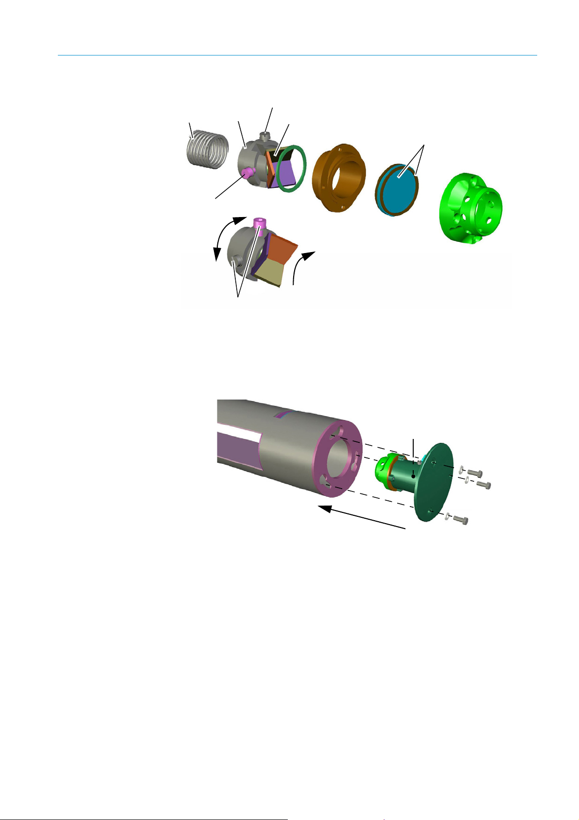
Fig. 50: Probe reflector assembly
Spring
Triple holder
Triple
Slotted screw
Socket screw
Hollow triple repositioned
(e.g. –90°)
Wedge window with
graphite seals
Socket and slotted screw positions on
reflector enclosure swapped
Holder (triple-side)
Holder (flange-side)
Socket screw hidden
ANNEX 10
▸ Reassemble the reflector components in the reverse sequence (insert the reflector and
turn approx. 30° to the left to stop) and secure the reflector unit on the probe end.
Fig. 51: Positioning of probe reflector with probe aligned
8010100/YK22/V4-0/2015-12 | SICK OPERATING INSTRUCTIONS | GM700
Subject to change without notice
101
Page 100

INDEX
A
Absorption line ................................................................................... 78
Aqueous solution
............................................................................... 68
C
CAN bus
............................................................................................... 41
-Cable
Clearing
- Evaluation unit
- Evaluation unit not responding
-Troubleshooting Table
Conduit thread connection
............................................................................... 79
..................................................... 79
................................................................... 74
............................................................... 41
D
Designated user ................................................................................ 14
Diagnosis
- Current warning messages
........................................................... 43
G
GM700 HF version ............................................................................ 13
I
Important information
-Intended use
-Main hazards
- Main operating information
Intended use
- User (target group)
-Users, intended
.................................................................................. 14
................................................................................. 10
.......................................................... 10
...................................................................................... 14
......................................................................... 14
.............................................................................. 14
L
Laser class 1 ...................................................................................... 13
Laser safety
....................................................................................... 97
M
Manufacturer ..................................................................................... 16
Measured value
- Measuring function (general)
Measuring function (general)
Measuring Mode
Measuring operation
- Current dust concentration measured value
- Device malfunction, error message
- Maintenance or Service mode
-Malfunction
- Measuring operation
- Menu overview
-Operation
-Service
- Warning
- Warning message
................................................................................ 43
.................................................................................... 43
............................................................................... 43
........................................................................................ 43
............................................................................................ 43
.......................................................................................... 43
.......................................................................... 43
........................................................ 14
........................................................... 14
............................... 43
.............................................. 43
...................................................... 43
..................................................................... 43
O
Operating elements
-Graphic display
-Key panel
- Messages on operating and malfunction states
- Navigation and input
-System control
Operation
-Display contents
- Displaying, entering and setting parameters
-Function line
- Measuring operation
-Operating mode
- Password
.............................................................................. 42
........................................................................................ 42
......................... 42
..................................................................... 42
............................................................................... 42
............................................................................ 43
............................... 42
................................................................................... 43
..................................................................... 42
............................................................................. 43
........................................................................................ 43
P
Product identification ........................................................................ 16
Product name
..................................................................................... 16
R
Responsibility of user ........................................................................ 14
S
Serial No. ............................................................................................ 16
Signal words
......................................................................................... 3
T
Target groups (users) .........................................................................14
Troubleshooting Table
Type plate
........................................................................................... 16
....................................................................... 74
U
User
-Designated user
- Responsibility of user
User information “Laser safety”, page 102.
............................................................................. 14
..................................................................... 14
.................................... 12
W
Warming up time ................................................................................ 71
Z
Zero gas pump ................................................................................... 66
Zero path
............................................................................................ 68
102
8010100/YK22/V4-0/2015-12 | SICKOPERATING INSTRUCTIONS | GM700
Subject to change without notice
 Loading...