

Page 1

I
GM35 Probe
Gas Analyzer for CO, N2O, CO2 and H2O
Version with Measuring Probe
Installation, Operation, Maintenance
MMMOPERATING INSTRUCTIONS
OPERATING INSTRUCTIONS
MMM
Page 2

Document ID
Title: Operating Instructions GM35
Part No.: 8009389
Release: 2015-08
Described Product
Product name: GM35
Version: 3-0
Manufacturer
SICK AG
Erwin-Sick-Str. 1 · 79183 Waldkirch · Germany
Phone: +49 7641 469-0
Fax: +49 7641 469-1149
E-Mail: info.pa@sick.de
Place of Manufacture
SICK AG
Nimburger Str. 11 · D-79276 Reute · Germany
Legal Information
This work is protected by copyright. All rights derived from the copyright shall
be reserved for SICK AG. Reproduction of this document or parts of this document is
only permissible within the limits of the legal determination of Copyright Law.
Any modification, shortening or translation of this document is prohibited without the
written permission of SICK AG.
The trademarks stated in this document are the property of their respective owner.
© SICK AG. All rights reserved.
Original document
This document is an original document of SICK AG.
2
8009389/YN39/V3-0/2015-08| SICKOPERATING INSTRUCTIONS | GM35
Subject to change without notice
Page 3

Contents
Contents
CONTENTS
1 Safety Information..................................................................................... 9
1.1 Permissible users............................................................................................ 9
1.2 Correct handling.............................................................................................. 9
1.3 Safety............................................................................................................... 9
1.4 Behavior during purge air failure..................................................................10
2 Product Overview .....................................................................................11
2.1 Use and proper application ..........................................................................11
2.1.1 Conformities and certifications ....................................................11
2.1.2 Overview of standard components ..............................................12
2.1.2.1 Measuring probe in detail.........................................14
2.1.2.2 GMP – probe with open measuring gap and vertical
purge air outlet..........................................................14
2.1.3 GM35 options and accessories ...................................................18
2.2 Functional principle ......................................................................................19
2.2.1 Opto-electronic in-situ measuring principle.................................19
2.2.2 Signal evaluation ..........................................................................20
2.2.3 Automatic check cycles ................................................................21
3 Project Planning Information................................................................. 22
3.1 Work steps from system selection to start-up .............................................22
3.2 Project Planning Checklist ............................................................................23
3.3 Initial onsite installation ...............................................................................26
3.3.1 Assembly preparation at the measuring point ............................26
3.3.2 Uncovering the duct......................................................................27
3.3.3 Installing the flange with tube......................................................27
3.3.3.1 Installation steps: Fitting the flange with tube ........28
3.3.4 Installation preparation for the purge air unit .............................29
3.3.5 Duct insulation..............................................................................29
3.3.6 Installation preparation for the evaluation unit ..........................30
3.4 Preparations for electrical installation .........................................................30
3.5 Electrical protection ......................................................................................30
3.6 Specifications on electric isolation of the EvU.............................................30
3.6.1 Electrical installation safety information .....................................30
3.7 Electrical protection ......................................................................................32
3.8 Specifications on electric isolation of the EvU.............................................32
3.9 Laying connection lines ................................................................................33
3.9.1 CAN bus wiring ..............................................................................34
4 Installation ................................................................................................36
4.1 Preparations..................................................................................................36
4.1.1 Checking the scope of delivery ....................................................36
4.1.2 Installation prerequisites..............................................................36
8009389/YN39/V3-0/2015-08| SICK OPERATING INSTRUCTIONS | GM35
Subject to change without notice
3
Page 4

CONTENTS
4.2 Fitting system components .......................................................................... 37
4.2.1 Information on the SR-unit and measuring probe ...................... 37
4.2.2 Installing the purge air unit.......................................................... 37
4.2.3 Terminal box (option) ................................................................... 38
4.3 Installing the evaluation unit........................................................................ 39
4.3.1 Installing the evaluation unit – sheet metal enclosure version. 39
4.3.2 Installing the evaluation unit – cast enclosure version.............. 40
4.4 Electrical connection of system components.............................................. 41
4.4.1 Electrical connection for the purge air unit................................. 41
4.4.2 CAN bus wiring options ................................................................ 42
4.4.3 Electrical connection of the evaluation unit ............................... 44
5 Handling the Evaluation Unit .................................................................47
5.1 User qualifications........................................................................................ 47
5.2 Operating elements ...................................................................................... 47
5.2.1 Function buttons and menu overview ......................................... 48
5.2.2 Display contents........................................................................... 49
5.2.3 Menu structure............................................................................. 49
5.2.3.1 Menu structure Measuring Mode ............................ 49
5.2.3.2 Menu structure Diagnosis ........................................ 50
5.2.3.3 Menu structure Calibration ...................................... 50
5.2.3.4 Menu structure Configuration .................................. 51
5.2.3.5 Menu structure Maintenance Mode (Maint) ........... 52
6 Connecting the System Control Unit - SCU........................................... 53
6.1 SCU connection to the GM35....................................................................... 53
6.1.1 Electrical connection of the SCU to the GM35 ........................... 53
6.1.2 Configuring and operating using SOPAS ..................................... 53
6.1.3 Connecting the GM35 evaluation unit via the SCU operating
unit................................................................................................ 55
6.1.4 Direct serial connection to the GM35 evaluation unit .............. 57
6.1.5 Changing the user level ............................................................... 59
6.1.6 Menu overview (menu tree) ........................................................ 60
6.1.7 Measured values.......................................................................... 60
6.1.8 Menu Parameter .......................................................................... 61
6.1.9 Menu Adjustment ......................................................................... 66
6.1.10 Menu Diagnosis............................................................................ 70
6.1.11 Menu Maintenance ...................................................................... 72
7 Start-up...................................................................................................... 75
7.1 Preparations ................................................................................................. 75
7.1.1 Required qualifications and further prerequisites...................... 75
7.1.2 Start-up procedure overview........................................................ 75
7.2 General preparation ..................................................................................... 75
7.2.1 Required tools and materials for the installation ....................... 76
4
8009389/YN39/V3-0/20 15-08| SICKOPERATING INSTRUCTIONS | GM35
Subject to change without notice
Page 5

CONTENTS
7.3 Mechanical preparations for the SR-unit and reflector ...............................77
7.3.1 Checking the scope of delivery ....................................................77
7.3.2 Transport safety devices ..............................................................77
7.3.3 Cleaning the optical interface ......................................................78
7.4 Aligning the measuring probe in flow direction ...........................................79
7.4.1 Installing the SR-unit on the measuring probe............................80
7.5 Adjustment work ...........................................................................................82
7.5.1 Prerequisites and location selection for adjustment work .........82
7.5.2 Adjustment preparations..............................................................83
7.5.3 Aligning the optical axis of the measuring probe ........................84
7.5.4 Performing zero adjust .................................................................87
7.6 Starting measuring operation.......................................................................88
7.6.1 Starting up the purge air supply...................................................88
7.6.2 GPP measuring probes: Power supply .........................................89
7.6.3 Installing the GM35 SR-unit and measuring probe on the duct.89
7.6.4 Electrical connections and checking the optical alignment .......90
7.6.5 Weatherproof cover ......................................................................92
7.6.6 Evaluation unit start-up ................................................................93
7.6.7 Setting up the SCU System Control Unit .....................................93
7.6.7 Mapping Table...........................................................93
7.6.7 Measured values on SCU – Measured value (MV) ..93
7.6.7 Control values on SCU – Monitor values (MO).........93
7.6.7 Operating state of the GM35 – State (S) .................94
8 Test Gas Measurement with GPP Measuring Probes.........................96
8.1 One-off preliminary measurement/determining the settings .....................97
8.2 Manual gas test ............................................................................................98
9 Maintenance............................................................................................. 99
9.1 Safety.............................................................................................................99
9.2 Preparation and general preparatory work ............................................... 101
9.3 Maintenance work on SR-unit and measuring probe ............................... 103
9.3.1 Taking the SR-unit with measuring probe off the sample
gas duct...................................................................................... 103
9.3.2 Visual inspection and enclosure cleaning ................................ 104
9.3.3 Cleaning the optical interfaces on the SR-unit......................... 104
9.4 Maintenance work on the purge air supply .............................................. 106
9.4.1 Safety ......................................................................................... 106
9.4.2 General information on maintenance work on the purge
air supply.................................................................................... 106
9.4.3 Preparation and general inspection ......................................... 106
9.4.4 Checking and replacing the purge air filter .............................. 107
9.4.5 Restarting and checking the purge air unit .............................. 109
8009389/YN39/V3-0/2015-08| SICK OPERATING INSTRUCTIONS | GM35
Subject to change without notice
5
Page 6

CONTENTS
9.5 Resuming Measuring mode .......................................................................109
9.5.1 Inserting in the sample gas duct ...............................................109
9.5.2 Electrical connection..................................................................110
9.5.3 Checking and adjusting the optical alignment of GM35 .........111
9.5.4 Completing maintenance work at the measuring point ...........112
9.6 Evaluation unit (EvU) ..................................................................................112
9.7 Box measuring: Checking the measuring ducts for CO or N
and CO
......................................................................................113
2
O
2
9.7.1 Determining the necessary test gas concentration ..................113
9.7.2 Carrying out measurement ........................................................113
9.7.3 Restart Measuring mode ...........................................................115
9.8 Box measuring: Checking the measuring ducts for H
CO
..............................................................................................116
2
O and
2
9.8.1 Setpoint values........................................................................... 116
9.8.2 Carrying out measurement ........................................................116
9.8.3 Restart Measuring mode ...........................................................118
10 Troubleshooting and Clearing Malfunctions......................................119
10.1 Malfunction categories/possible effects................................................... 119
10.2 Purge air failure .......................................................................................... 119
10.3 Integrated monitoring and diagnosis system ............................................120
10.3.1 Troubleshooting and clearing malfunctions, evaluation unit...121
10.3.2 Error messages for the GM35 SR-unit ......................................121
10.3.3 Error messages for the measuring probe .................................124
10.3.4 Warning messages for the GM35 SR-unit.................................124
10.3.5 Warning messages for the measuring probes ..........................126
10.3.6 Further tips on troubleshooting .................................................126
11 Technical Data, Consumables and Spare Parts...............................128
11.1 Data Tables.................................................................................................128
11.1.1 Measuring components and accuracy ......................................128
11.1.2 Stability....................................................................................... 129
11.1.3 GM35-system components
11.2 Dimension drawings ...................................................................................132
11.2.1 GM35 SR-unit dimensions........................................................132
11.2.2 Open measuring probe - GMP, dimensions...............................133
11.2.3 GPP measuring probes dimensions .......................................... 134
11.2.4 Dimension drawing of GM35 evaluation unit, sheet metal
enclosure ....................................................................................135
11.2.5 Dimension drawing for GM35 evaluation unit, cast enclosure136
11.2.6 Purge air unit dimension drawing.............................................. 137
11.2.7 Weatherproof covers dimension drawings................................ 137
11.2.8 Terminal box for CAN bus connection, dimension drawing......139
11.2.9 Flange with tube, dimension drawing and Version Table......... 139
................................................ 130
6
8009389/YN39/V3-0/20 15-08| SICKOPERATING INSTRUCTIONS | GM35
Subject to change without notice
Page 7

CONTENTS
11.3 Consumables and spare parts .................................................................. 140
11.3.1 Consumable parts for 2-years operation .................................. 140
11.3.2 Spare parts for the sender/receiver unit.................................. 140
11.3.3 Probe spare parts ...................................................................... 143
11.3.4 Spare parts for the evaluation unit........................................... 144
11.3.5 Spare parts for purge air unit.................................................... 145
11.3.6 Spare parts, miscellaneous....................................................... 145
11.3.7 Fixing accessories...................................................................... 145
11.3.7 Fixing accessories, measuring probe - flange....... 145
11.3.7 Fixing accessories, SR-unit - measuring probe ..... 145
8009389/YN39/V3-0/2015-08| SICK OPERATING INSTRUCTIONS | GM35
Subject to change without notice
7
Page 8

CONTENTS
8
8009389/YN39/V3-0/20 15-08| SICKOPERATING INSTRUCTIONS | GM35
Subject to change without notice
Page 9

1 Safety Information
The following information and guidelines apply to the Gas Analyzer with Measuring Probe
GM35 described in this “Operating Instructions” document, and are valid for all user
groups performing any work on or using the analyzer.
1.1 Permissible users
All planning, assembly, installation, start-up, maintenance and repair work must be carried
out by adequately instructed personnel only and checked by skilled persons.
Persons responsible for safety must ensure the following:
• All safety-relevant work is carried out by qualified personnel only.
• Qualified persons are those who, based on their training, experience or instruction as
well as their knowledge of relevant standards, regulations, accident prevention rules and
plant conditions, are authorized by those responsible for safety for personnel and the
plant to carry out such work. It is decisive that these persons can recognize and avoid
possible hazards in a timely manner. Skilled persons are persons according to
DIN VDE 0105 or IEC 364 or directly comparable standards such as DIN 0832.
• These persons have access to the documentation supplied with the system as well as the
relevant technical documentation for all work carried out, and these persons adhere to
the information in this documentation in order to prevent danger or damage.
SAFETY INFORMATION
1.2 Correct handling
To ensure safety precautions are observed and the device is used for its intended purpose,
it is important that:
• The system be used in accordance with the technical data and specifications regarding
permissible usage, assembly, connection, ambient, and operating conditions. These
conditions are governed by the order documents, user information (type plates etc.), as
well as the documentation supplied with the system, which includes these
Operating Instructions.
• Users act in accordance with local, system-specific conditions and with due
consideration paid to operational hazards and specifications.
• All measures necessary for conservation of value are observed, e.g. during transport and
storage and/or maintenance and inspection.
1.3 Safety
WARNING: Risk through incorrect use
Equipment-internal protection devices can be impaired when the device is not
used as defined.
▸ Read the Manual before installation, start-up, operation and
maintenance and observe all information on using the equipment.
NOTICE: Responsibility for the safety of a system
The safety of the system in which the equipment is integrated is the
responsibility of the person setting up the system.
Basic measures to prevent property damage and injury to persons
Improper usage or improper handling of Gas Analyzer GM35 can damage health or
material.
8009389/YN39/V3-0/2015-08| SICK OPERATING INSTRUCTIONS|GM35
Subject to change without notice
9
Page 10

SAFETY INFORMATION
▸ Therefore, in order to prevent damage, the relevant safety information and valid safety
If the GM35 is used as a sensor in combination with a control system, the operator must
ensure that a failure or malfunction on the GM35 cannot lead to unallowed hazardous
operating states or damage.
Protection against hazards through electrical equipment
GM35 system components include electrical equipment designed for use in industrial highvoltage plants where the relevant standards and regulations must be observed.
▸ Disconnect mains lines before working on mains connections or live parts.
Protection against hazards through gases
▸ Wear suitable protective clothing and mask when using hot and/or aggressive sample
▸ Never open the enclosure or switch off the purge air feed without taking appropriate
Troubleshooting precautions
The operator must ensure that:
• Maintenance personnel can be alerted immediately and at any time.
• Maintenance personnel are trained to be able to respond to malfunctions on the GM35
• Suitable protective equipment, tools and auxiliary means are available at all times.
• Malfunctions are analyzed by qualified personnel, faults corrected, and operation
regulations must be observed.
gases resp. with high dust loads.
protective measures when the duct is pressurized.
and correctly clear the operational malfunction involved.
optimized to prevent similar malfunctions in the future.
1.4 Behavior during purge air failure
The GM35 measuring system configurations demand immediate measures to protect the
measuring system should the purge air supply fail.
▸ Measures for purge air supply failure,
see “Purge air failure”, page 119.
10
8009389/YN39/V3-0/2015-08| SICKOPERATING INSTRUCTIONS|GM35
Subject to change without notice
Page 11

2Product Overview
2.1 Use and proper application
PRODUCT OVERVIEW
The GM35 in-situ gas analyzer continuously measures the concentration of CO
CO or N2O, and in gas ducts – as single or simultaneous measurement depending on the
device variant. As in-situ measuring system, the GM35 determines the measured values
directly in the gas-carrying duct without extracting any samples.
• Emission monitoring
The GM35 determines and quantifies pollutants and reference values in gases reliably,
quickly and precisely.
• Process analysis and control
The reliability, precision, and short response time of the GM35 are decisive advantages in
the efficiency of control circuits in all processing creating CO, N
and drying plants are reliably monitored and efficiently controlled.
2.1.1 Conformities and certifications
Many areas of application require conformity with certain specifications. The Gas Analyzer
with Measuring Probe GM35 complies with the following requirements:
• Guidelines regarding qualification tests for measuring equipment intended for
continuous emission measurements
• Performance testing of ± 2% precision of the measuring range end value (TÜV certified)
• Conformity according to EN 14181 and suitability for emission measurement in plants
according to the 13
components CO, CO
• Conformity with the GOST regulation, Certificate No. DE.C.31.001.A No. 11933
• Conformity with the U.S. EPA regulation CFR 40, Parts 60, 75 and 29 CFR 1310
• KAITEC certified (Korea)
• EMV conformity in accordance with EN 50081-1/EN 50082-2
• CE conformity in accordance with EC Directive EMC 89/336/EWG
• The manufacturer SICK is certified according to ISO 9001
• EC Directive LVD 2006/95/EC
• EU Directive EMC 2004/108/EC
• Applied EN standards:
• EN 61010-1, Safety requirements for electrical equipment for measurement, control and
laboratory use
• EN 61326, Electrical equipment for measurement, control and laboratory use - EMC
requirements
O- and CO2. Incinerating
2
th
, 17th BImSchV and the TI Air, KAITEC certified (Korea) for
and H2O (Cross-Duct and GMP measuring probe versions)
2
2, H2
O and
8009389/YN39/V3-0/2015-08| SICK OPERATING INSTRUCTIONS|GM35
Subject to change without notice
11
Page 12
PRODUCT OVERVIEW
maintcalpardiag
GM 35
Evaluation Unit
CO
CO
2
H 2 O
mg/
m
3
236
Ref. conditions
Hum: wet
Measuring
Operation
Service
Warnin
Malfunction
Purge air unit SLV4
(not required when
using GPP measuring
probes)
GM35 sender/receiver unit
with GMP measuring probe
Temperature
sensor
Evaluation unit
EvU
CAN bus
CAN
Inputs/outputs
analog, binary
Interfaces to plant
peripherals:
•Host computer
•Sensors
• Measured data
processing
• Status signals
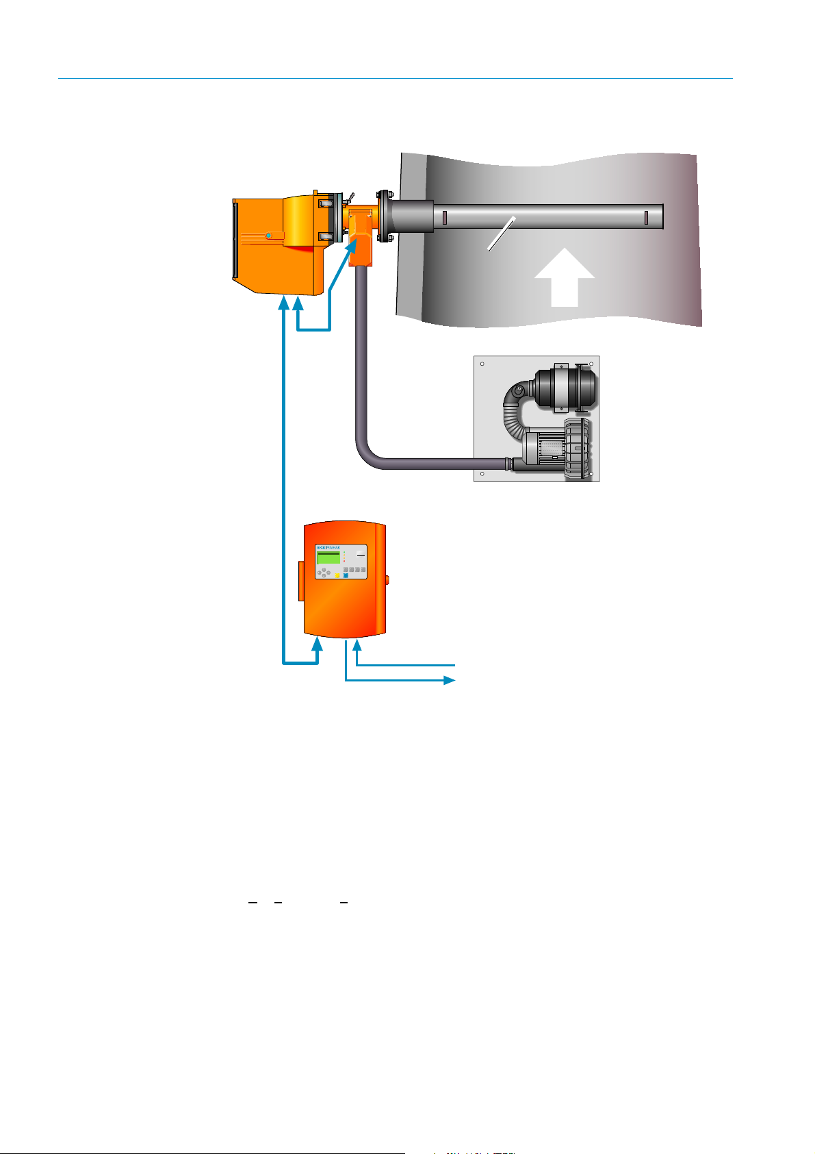
2.1.2 Overview of standard components
Fig. 1: GM35 system overview
• Sender/receiver unit (SR-unit)
Contains the main optical and electronic subassemblies of the measuring system. Records
gas concentrations, calculates measured values, measures components CO or N
and H
O; both singly and simultaneously in combinations.
2
O, CO2
2
• Measuring probe
Measuring probes are available in open design versions with integrated purge air guidance
system (GMP) as well as versions with a gas-permeable diaphragm not requiring purge air
(GPP: G
as Permeable Probe). Both versions are described from page 14 onwards.
• Purge air unit
Provides purge air supply for the SR-unit with a GMP measuring probe (open design) and
protects against contamination and high gas temperatures. The blower types for the
SR-unit resp. reflector are designed differently depending on the application.
12
8009389/YN39/V3-0/2015-08| SICKOPERATING INSTRUCTIONS|GM35
Subject to change without notice
Page 13
PRODUCT OVERVIEW
• Evaluation unit
The evaluation unit in the GM35 measuring systems serves as user interface and
prepares and outputs the measured values and performs control and monitoring
functions. The EvU can be installed near the SR-unit; if necessary, however, it can also
be installed up to 1000 m from the measuring point, e.g. in a central control/monitoring
room in an industrial plant.
The evaluation unit carries out the following tasks, for example:
– Output of measured values, computed data and operating states
– Communication with the peripheral equipment
– Output of error messages and other status signals
– Control of automatic test functions and access during service (diagnosis)
• Connection cables
Cable type Part No.
Cable*) (CAN bus), SR-unit – measuring probe, length 1.0 m 2023704
[1]
Cable
Cable
(CAN bus), SR-unit – evaluation unit, length 4 m
*)
, measuring probe – filter monitor for purge air unit, length
5m
*)
2 cables
, measuring probe – filter monitor for purge air unit, length
2 m as extension
Cable, measuring probe – filter monitor for purge air unit, length 3 m
as extension
Scope of
delivery
2032143
6025923
6028663
[1]Included in scope of delivery
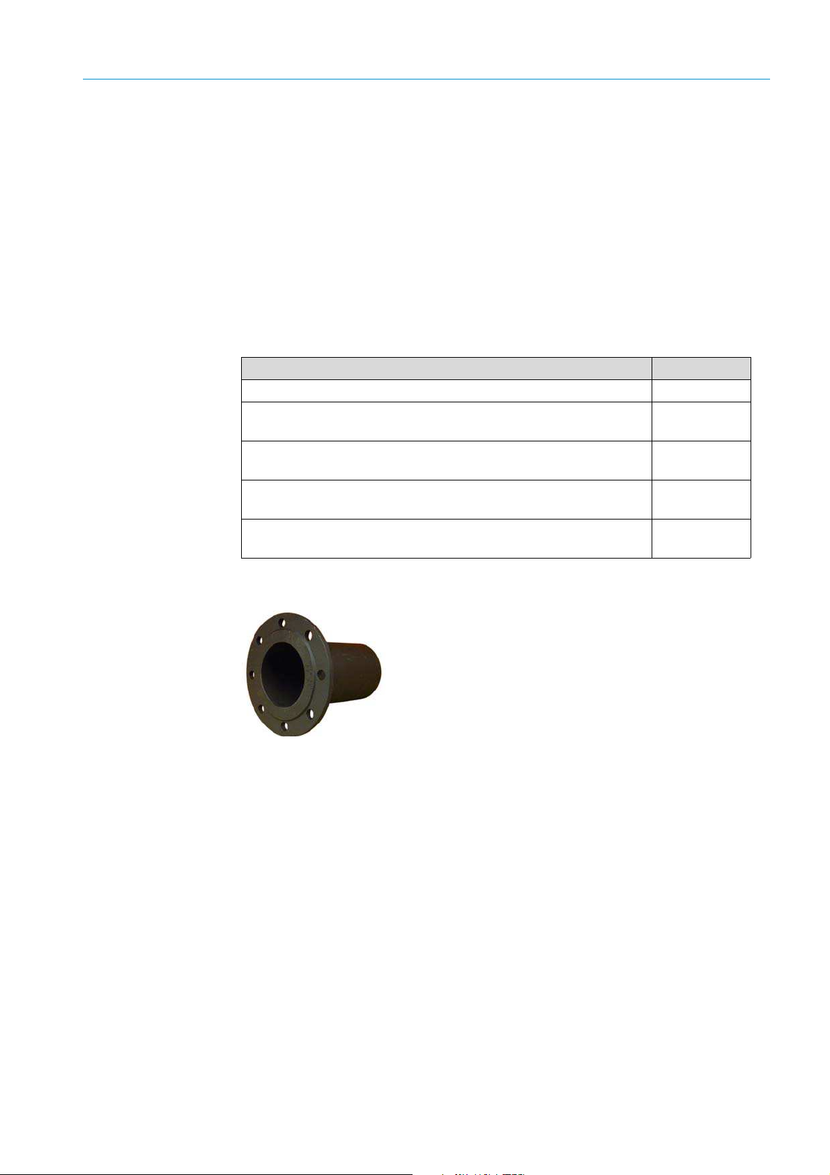
• Flanges with tube
To install the SR-unit with measuring probe on the gas duct.
The purge air fixtures onto which the SR-unit and reflector are
later mounted are secured to the flanges. Dimension drawing
and order data,
page 139. ANSI or DIN flanges provided by the
customer can be used alternatively to the flanges supplied.
8009389/YN39/V3-0/2015-08| SICK OPERATING INSTRUCTIONS|GM35
Subject to change without notice
13
Page 14
PRODUCT OVERVIEW
2.1.2.1 Measuring probe in detail
EPA conformity When using a GPP probe, an audit measurement in compliance with EPA CFR 40 Part 60 or
Part 75 can be performed with the device mounted.
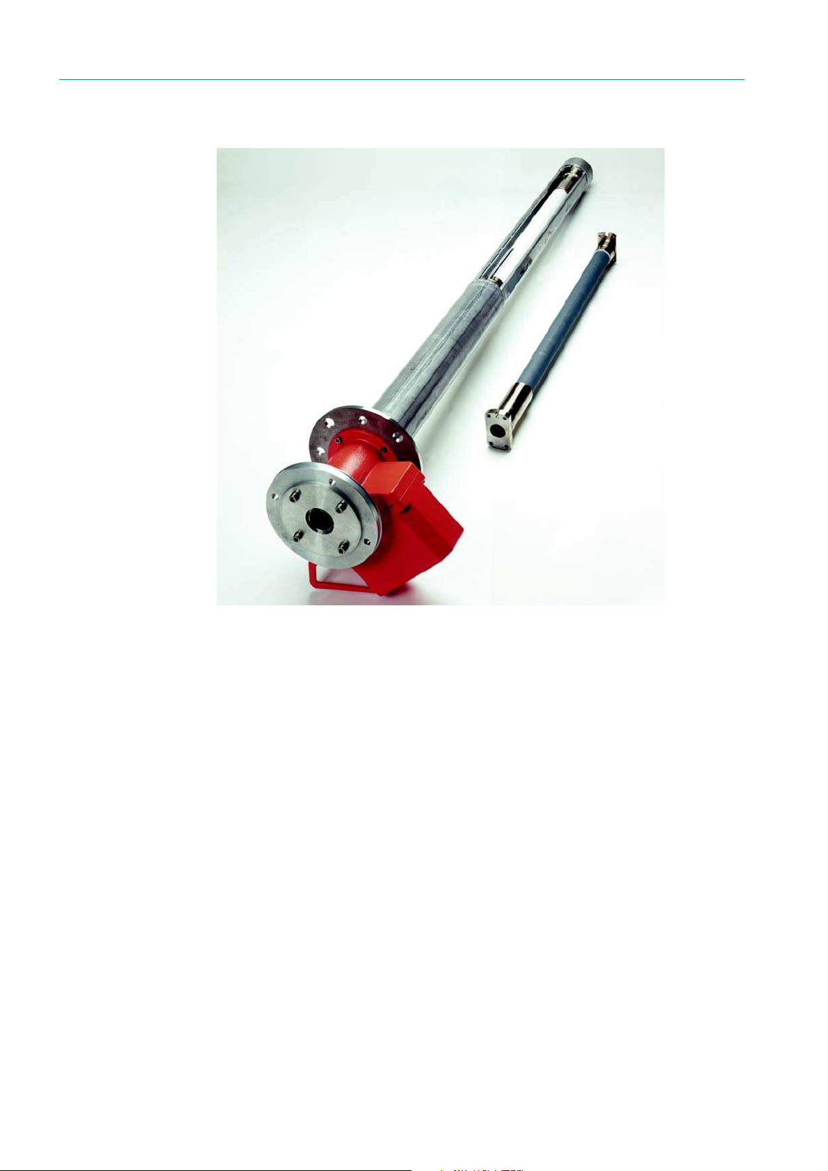
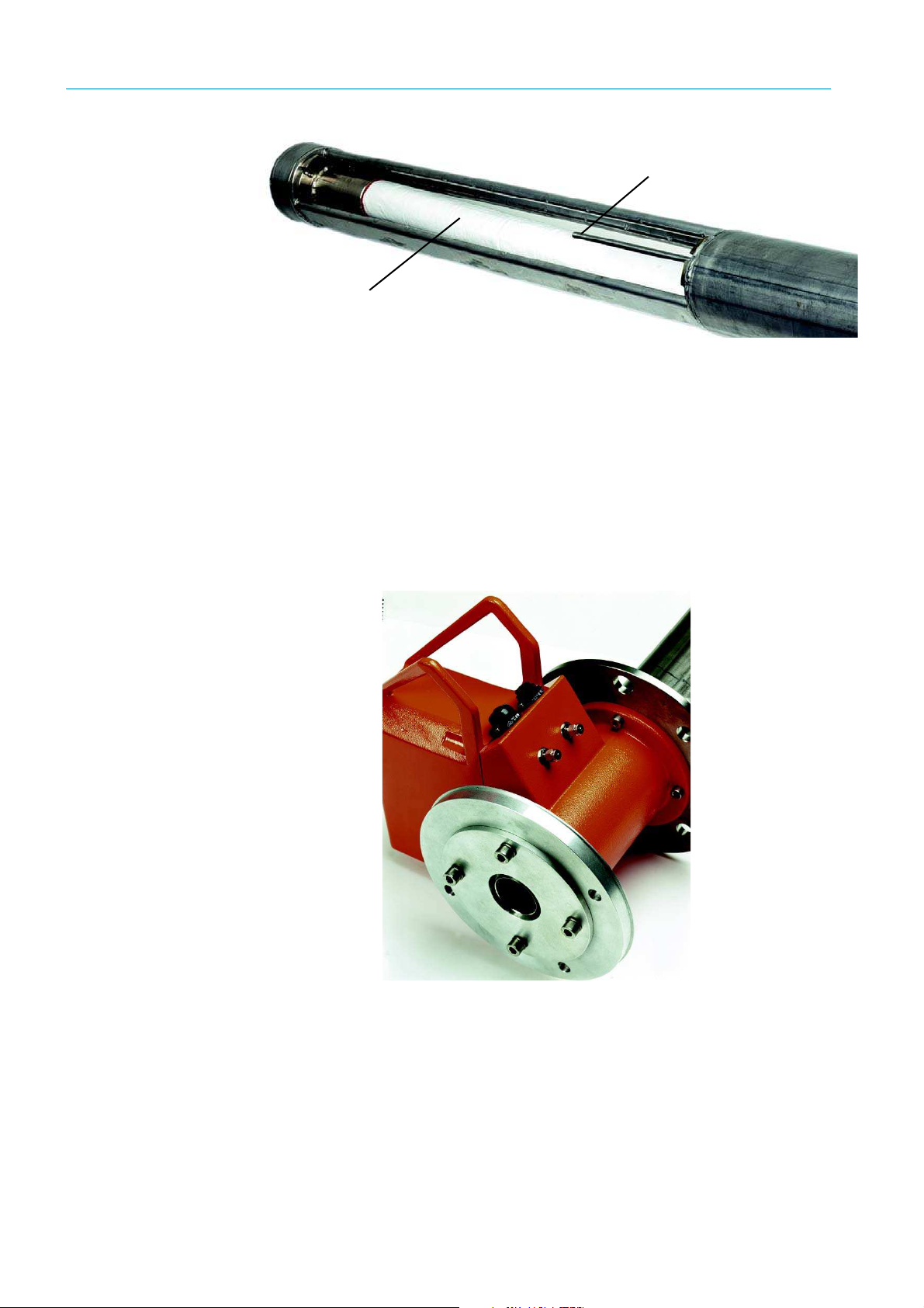
2.1.2.2 GMP – probe with open measuring gap and vertical purge air outlet
Shortest response times and resistance against high temperatures characterize measuring
probes of the GMP series. A continuous purge air supply is required for operation. In the
current GMP probe series, the air is outlet into the duct at 90° to the gas flow (directed
purge air).
The GMP probe has a closing device towards the opening for sample gas and is operated
using the lever on the probe flange.
14
8009389/YN39/V3-0/2015-08| SICKOPERATING INSTRUCTIONS|GM35
Subject to change without notice
Page 15
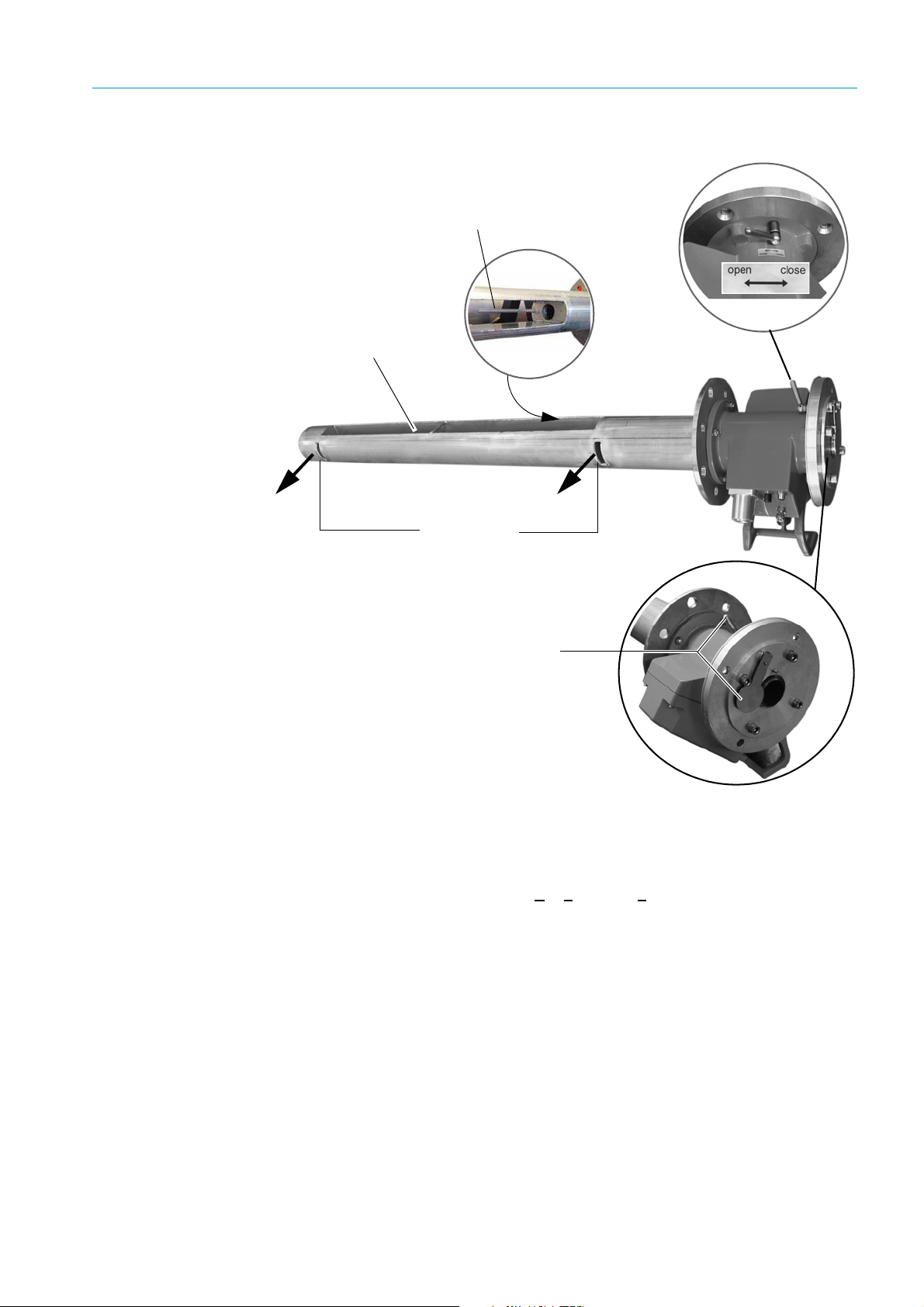
PRODUCT OVERVIEW
Tempera ture sensor
PT 1000
Purge air outlet
Open measuring path
(measuring gap)
Lever position
Lever and closing
device: Open
Fig. 2: GMP measuring probe (with open measuring gap)
GPP – gas diffusion probe as dry or wet version
These GPP probe versions are more suitable for higher dust contents than GMP probes
because the GMP probes separate dust particles at the filter element which keeps the dust
away from the measuring path. The GPP (G
as Permeable Probe) is also the best measuring
probe choice for audit measurements according to EPA specifications as well as for low
flow rates or irregular flow profiles.
8009389/YN39/V3-0/2015-08| SICK OPERATING INSTRUCTIONS|GM35
Subject to change without notice
15
Page 16
PRODUCT OVERVIEW
Temperature sensor PT 1000
Ceramic filter or Teflon/
ceramic filter, gas permeable
Fig. 3: Measuring gap for GPP measuring probe
The two versions of the GPP differ with regard to the respective filter making them suitable
for different applications,
see page 17.
Advantages of GPP
probes
GPP probes do not require a purge air supply and are easy to maintain. They are fitted with
an automatic heater for reliable prevention of condensate on the optical interfaces. The
electronic components for the heater regulator, and temperature and pressure
measurements, are located protected in a stable cast housing which forms the measuring
probe section between the duct flange and the SR-unit.
The Figure below shows this housing fitted with the electrical connections for the CAN bus
and power supply as well as the test gas connection which supports audit measurement
according to EPA Directive CFR 40, Part 60 or Part 75.
16
Fig. 4: Electronic connections on the GPP probe
GM35 measuring probes in comparison
This Table shows an overview of the features of the different measuring probes. All
measuring probe versions are compatible with all SR-units. The SR-unit is calibrated to the
respective probe length on delivery.
8009389/YN39/V3-0/2015-08| SICKOPERATING INSTRUCTIONS|GM35
Subject to change without notice
Page 17
PRODUCT OVERVIEW
Measuring probe GMP (open probe) GPP (dry)
Measuring path open in flow
Version
direction; purge air guidance
with outlet aligned 90° to
gas flow
[1]
Max. gas temperature
430 °C
N20 measurement up to
180 °C
Gas check according to EPA
specification possible
–Yes
Purge air supply required Yes –
Heating on optical interfaces
in the probe
– Yes, with integrated control
Flow rate of sample gas 1...40 m/s < 40 m/s
Suitable for wet sample gas Yes –
Maximum duct pressure
Measurable components
System-response time (T
Duct diameter
[3]
Dust concentration < 2 g/m
±120 hPa, depending on
purge air supply
[2]
CO or N20, CO2, H2OCO or N
) ≥ 5s ≥ 120 s
90
> 360 mm > 300 mm
3
act < 30 g/m3 act
Probe lengths available [m] 1.0/1.5/2.0 / 2.5 1.0/ 1.5/2.0
Active measuring paths
available [mm]
**
250/500/750/1000/1250 250/500/750/1000
Gas diffusion probe with
ceramic filter, for dry
sample gas
430 °C
N20 measurement up to
180 °C
±120 hPa
0, CO2, H2O
2
Table 1: Comparison Table for GM35 measuring probes (dimension
drawings,
[1] The maximum temperature used for the measurement depends on the application.
[2] Probes are fitted with gold-plated hollow triples when CO or N20 is measured as component or with other
components, otherwise probes with quartz glass are used.
[3] Probes with shorter active measuring paths are available on request (may be required for higher concentrations
or smaller duct diameters)
see page 128)
8009389/YN39/V3-0/2015-08| SICK OPERATING INSTRUCTIONS|GM35
Subject to change without notice
17
Page 18

PRODUCT OVERVIEW
Special versions Apart from the standard probes shown above, other versions made from materials
especially resistant to acid are available (1.4539 and PVDF). Special versions can be
manufactured according to customer demands on request.
2.1.3 GM35 options and accessories
• Automatic beam tracking
Ensures exact alignment of the measuring path to the probe (open and GPP version) under
difficult and changing measurement conditions, such as, for example, large temperature
fluctuations.
• CAN bus extension cable 15 m
A 15 m extension cable, ready for connection, is available when the evaluation unit is to be
installed more than 2 m away from the SR-unit.
• Terminal box for CAN bus
For even greater distances between SR-unit and EvU, an optional terminal box can be used
for the connection via the CAN bus cable provided by the customer. The total length of the
CAN bus connections in the GM35 measuring system can be up to 1000 m in this case.
However, the EvU is normally installed close to the SR-unit for easy operating at the
measuring point. Section
to use the terminal box.
• Angle flange for zero point measurement
Some adjustments must be made outside the duct in an atmosphere free from sample
gas. A suitable angle flange that can be screwed to the mounting flange is available to
enable carrying out these adjustments easily and directly at the measuring point. The duct
is sealed and the SR-unit with measuring probe is mounted in front of the duct opening, at
a right angle to the duct, using this bracket.
“Preparations for electrical installation”, page 30 describes how
• Weatherproof covers for SR-unit and purge air unit
Required for outdoor installation – dimension drawings,
see page 128.
• Line writer, single or multi-duct
For measured value recording. Protocol(s) can of course be produced using customer
systems.
• Air heater for purge air supply
For special application conditions to prevent condensate. An air heater is required when
the difference between gas temperature and dew point temperature is too low. The
following practical rule of thumb serves as guideline:
An air heater is required when :
Gas temperature [°C] – dew point temperature [°C] < abs. humidity [%]
Values are compared without considering the units of measure.
18
8009389/YN39/V3-0/2015-08| SICKOPERATING INSTRUCTIONS|GM35
Subject to change without notice
Page 19
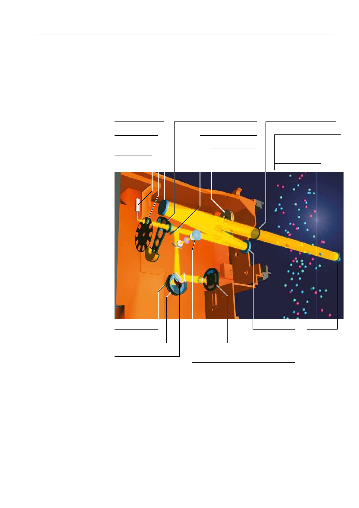
2.2 Functional principle
Reflector of
the measuring
probe
Front window of the SR-unit
Measuring path in the gas
duct (Measuring gap or
diffusion filter depending on
the probe)
Deflection mirror
Filter wheel and detector for
CO2 and H2O
CO detector
Cell wheel CO/N
2
Filter for CO measurement
Visor with opto-electronic adjustment tool
IR transmitter
lamp
Chopper
Lens mirror Reference filter pivot segment
Beam splitter
Zero point reflector
and blanking
diaphragm
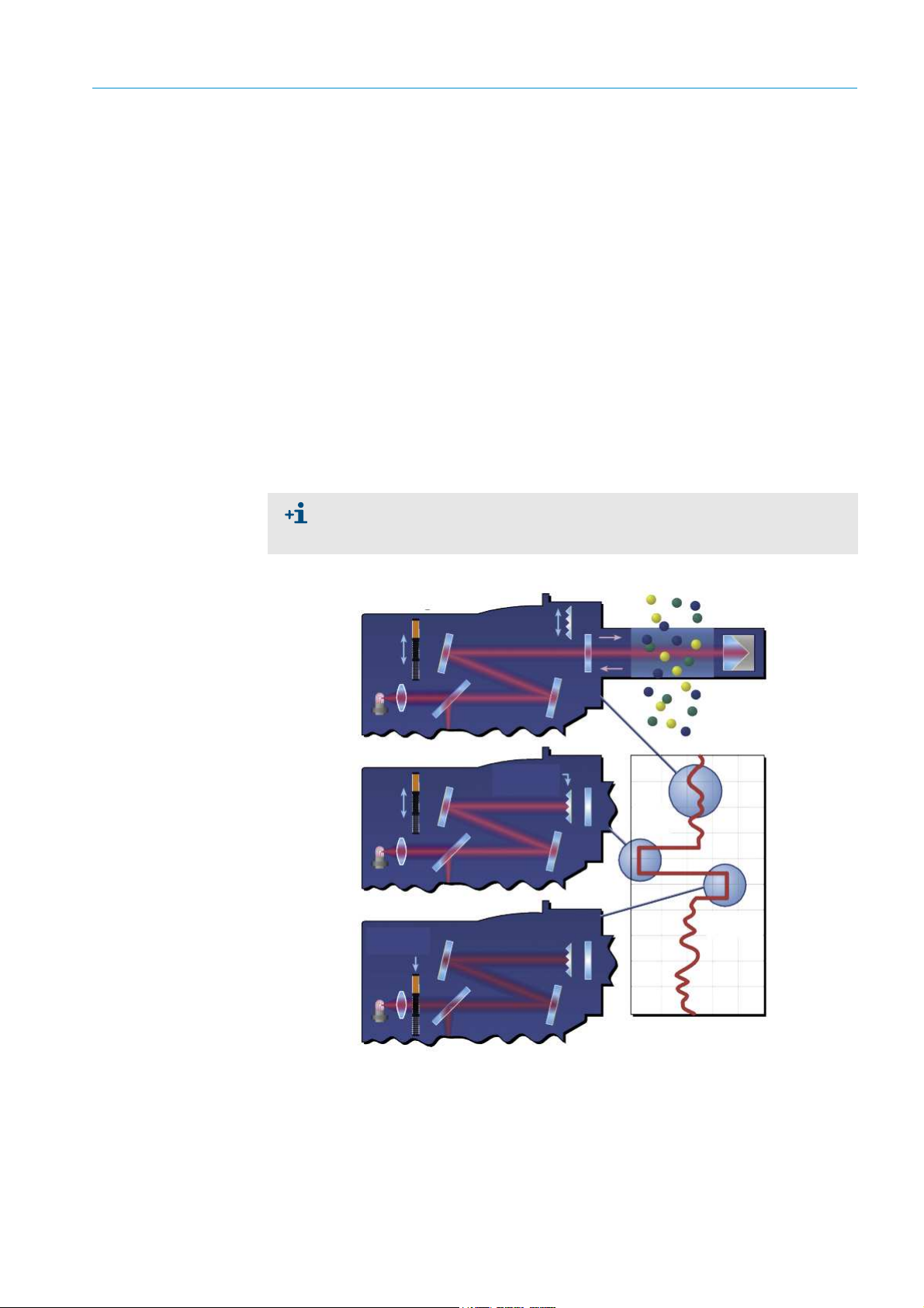
2.2.1 Opto-electronic in-situ measuring principle
The Gas Analyzer with Measuring Probe GM35 is based on in-situ technology with optoelectronic direct measurement. Measured values are recorded through no-contact
measurement directly in the gas flow across the entire duct cross-section (cross-duct). The
GM35 SR-unit determines the concentration of the respective gas component based on
wavelength-specific light absorption by the gas mixture in the active measuring path.
PRODUCT OVERVIEW
Fig. 5: Optics layout of the GM35
The beam from the sender/receiver unit (SR-unit) passes lengthwise through the active
measuring path (
see page 26) and is reflected by the reflector at the other end. The
reflected light from the beam splitter then passes through a filter or cell wheel to detectors
configured optionally to measure CO or N
received into its spectral components, the receiver elements record the absorption of the
gas molecules at characteristic points of the spectrum in the IR range of 1.6 to 4.9 µm.
0 as well as CO2 and H2O. By filtering the light
2
8009389/YN39/V3-0/2015-08| SICK OPERATING INSTRUCTIONS|GM35
Subject to change without notice
19
Page 20
PRODUCT OVERVIEW
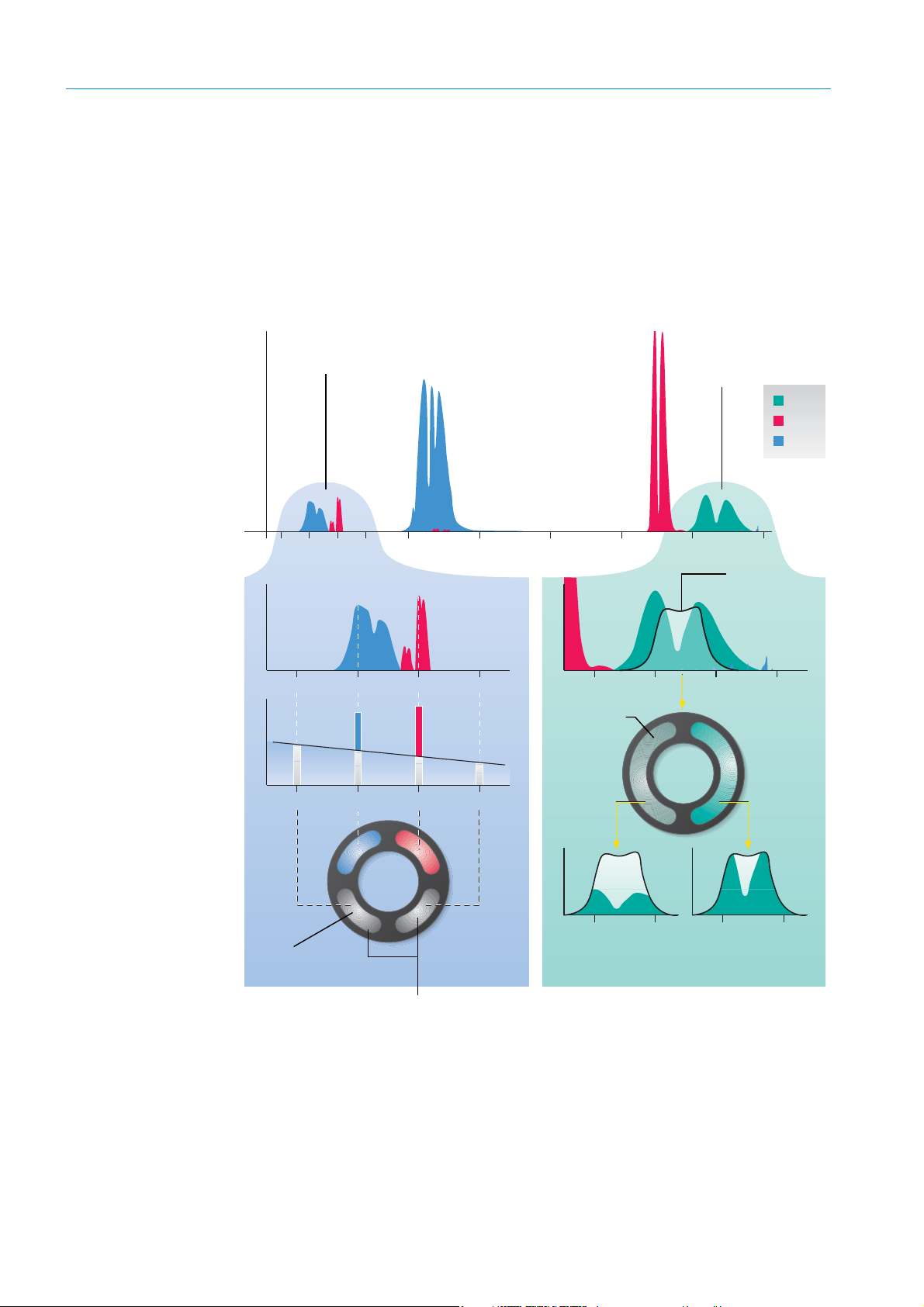
CO
CO
2
H2O
2000 2500 3000 3500 4000
λ
[nm]
4500 50001500
18001600 2000 2200
Ref. 2 H2OCO2Ref. 1
Absorpti
H2OCO
2
46004400 4800 5000
CO
N
2
CO
4600 4800 4600 4800
CO2 and H2O measurement in the
range of 1600– 2200 nm
CO or N
2
O measurement
in the range of
approx. 4500–4900 nm
Cell wheel
N
2
/CO
Absorption CO
≈ measured value
Absorption CO
= 100%
Filter wheel for
CO
2
and H2O
Reference filter for determining the
background absorption, free of crosssensitivities with other gas components
The CO or N
2
O- measured values are
determined from the signals at the detector with
absorption by the sample gas and with a cell
filled with the component to be measured.
Interference is eliminated
Tra nsmi ssi on
characteristic
line of the CO
measurement
filter
Absorption
Cross-sensitivities with gases other than those to be measured are avoided by selecting
these evaluation ranges within the IR spectrum in conjunction with the evaluation
algorithms used (see
2.2.2 Signal evaluation
The optimized algorithms of the GM35 evaluation electronics process the measurement
signals of the receiver elements together with the associated parameters in accordance
with the correlation procedure with optical filters for CO
gas for CO or N
O.
2
page 20).
and H2O and with cells filled with
2
Fig. 6: Evaluation of absorption spectrums for sample gases with the GM35
20
8009389/YN39/V3-0/2015-08| SICKOPERATING INSTRUCTIONS|GM35
Subject to change without notice
Page 21
2.2.3 Automatic check cycles
Measure
Zero point
Check
Zero point
Check point
(70% fsc)
Zero point reflector
Swivel element
Data recorder
To ensure a consistently high level of measuring precision, the GM35 SR-unit performs a
regular automatic check cycle in an adjustable interval (standard: Every 2 hours). In this
check cycle, the zero point is first determined by swiveling a zero point reflector into the
beam path. Reference filters are then moved into position to control the check point. The
spectral properties of the device are checked using a test gas cell. If a check cycle reveals
that the system is not functioning in accordance with the operation specifications, the
GM35 measuring system outputs appropriate error or warning messages.
Triggering options
1 Di 1 (falling edge): The check cycle can also be suppressed with this function.
2 Time interval, adjustable via the menu of the EvU.
Sequence
1 Check cycle is started.
2 Internal reference measurement is executed. Signal: Relay 3 (function check)
3 The zero point and check point are output on the EvU display and the assigned analog
outputs for 90 seconds each. Relay 3 remains active.
PRODUCT OVERVIEW
Observe the following for connecting to an emission computer: Measure the
time from the start to the output to compensate differences in the device
settings.
Fig. 7: Determining the check point
8009389/YN39/V3-0/2015-08| SICK OPERATING INSTRUCTIONS|GM35
Subject to change without notice
21
Page 22

PROJECT PLANNING INFORMATION
3 Project Planning Information
3.1 Work steps from system selection to start-up
Application changes
If the information regarding your application submitted with your purchase order has
changed, or if a device is to be used for an application other than the one that was
originally intended, please contact your local sales representative or our project planning
department to determine whether the device(s) can be used under the new conditions, and
whether readjustment or reparametrization is necessary.
The following steps are generally carried out before the measuring system is started up:
The version of the TCU-MS operating unit is selected according to the external signals to be
processed or output.
• Project planning
See planning checklist below
• Initial onsite installation
Following preparatory work normally carried out by the customer is described on
page 26:
• Flange assembly,
– Preparation for assembling the purge air unit, see page 29.
– Laying the signal and power supply cables to the measuring point, see Chapter 3.9 ,
page -33.
– Preparations for installing the EvU, see “Installation preparation for the evaluation unit”,
page 30
.
– Possibly preparation of signal cables for the interface to peripheral equipment, see
“Preparations for electrical installation”, page 30
• Device installation
To allow speedy start-up, the following components are normally installed ready for
operation before the start-up date;
see page 27.
see “Installation”, page 36.
– Purge air unit
– Evaluation unit
• Start-up
The actual start-up procedure is carried out by trained personnel or SICK Customer
Service. This work is described on
page 53. The main activities are adjustment tasks on
the GM35 system related to the application.
22
8009389/YN39/V3-0/2015-08| SICKOPERATING INSTRUCTIONS|GM35
Subject to change without notice
Page 23
PROJECT PLANNING INFORMATION
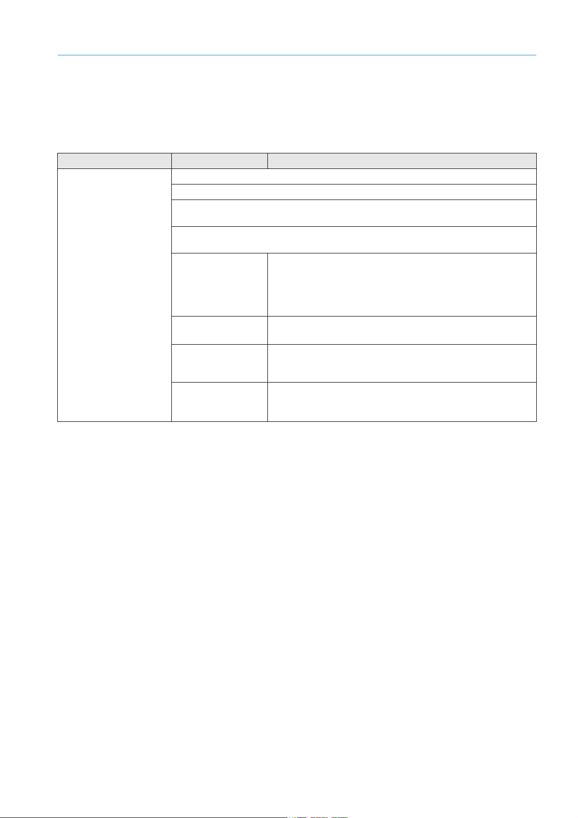
3.2 Project Planning Checklist
The following Checklist simplifies performing and controlling project planning measures
required before start-up in the correct sequence. Technical data and dimensional drawings
of system components,
Topic Task Measure/determination
Determination of
measuring point
Observe national
regulations such as
VDI 3950
Provide for unhindered inlet and outlet paths:
▸ For round duct cross-sections: 3 times the duct diameter
▸ For rectangular cross-sections: Hydraulic diameter
page 128 and following.
▸ If these specifications cannot be met: Inlet path > outlet path,
2
/3 : 1/3; uniform concentration spread whenever possible
e.g.
▸ Obtain official approval for emission measuring point.
Emission measuring
point
Application conditions
▸ Provide for calibration openings at easily accessible places.
▸ Ensure the GM35 and calibration probe do not influence
each other; the calibration gland should be located at a
minimum distance of 0.5 m away from the measuring device.
▸ Observe Technical Data for duct/ambient conditions!
▸ Gas temperature above/below dew point (dry/wet)
▸ Acc. to FGD wet :
Installation location
Pressure conditions
at the measuring
point
Select a version with active measuring path ≤ 500 mm when
a GMP probe is used.
▸ A fitting location with partial vacuum in the duct is ideal.
▸ For duct pressures > 10 mbar, please contact SICK to select
the correct purge air blower type.
4F (Cross-sectional area)
-------------------------------------------------------------------------------------=
D
U (Circumference)
Table 2: Project planning checklist
8009389/YN39/V3-0/2015-08| SICK OPERATING INSTRUCTIONS|GM35
Subject to change without notice
23
Page 24

PROJECT PLANNING INFORMATION
Topic Task Measure/determination
SR-unit, probe
See 3.3.1 “Assembly preparation at the measuring
point”, page 26
Select suitable flange
with tube
▸ Flange fitting is planned in steel ducts as standard;
corresponding flanges with tube are normally included in the
GM35 scope of delivery.
▸ Brick stacks or thick-walled ducts require a holding plate, to
be provided by the customer, and, if necessary, a longer
flange with tube, see Chapter 3.3.3 , page -27.
▸ If some of the components have not yet been delivered, you
may need to arrange an advance delivery of the flanges with
tube so that you can mount these as part of the preparations
for installation onsite.Alternatively, you can use a suitable
flange prepared onsite (or ANSI flange, check the Technical
Data, see page 128).
▸ Determine the alignment of the measuring gap of the GM35
measuring probe in gas flow direction.
▸ Provide a suitably sized opening for the tube of the mounting
flange.
▸ Install the flange with tube tilted slightly downwards (> 1°) to
prevent condensate deposits and therefore corrosion.
Duct openings
selection
▸ Provide for adequate clearance for installation and
maintenance activities for the duct insulation cutout.
▸ Plan sufficient clearance for pivoting the GM35 SR-unit,
removing the cable connector from the device, and pulling
the measuring probe out of the duct.
▸ Ensure the ambient temperature for the GM35 SR-unit is
between -20 and +55 °C (–40 °C during continuous
operation).
▸ For installation outdoors, plan a weatherproof cover.
▸ If adjustments are to be made at the measuring point
(prerequisites: clean, atmosphere free from sample gas;
protected from weather): order the angle flange for zero point
measurement (Part No. 2 017 833); when necessary, plan a
longer version of the flange with tube to ensure sufficient
distance from the duct.
▸ Plan installation location on the duct in immediate vicinity
(5 m) of the GM35 SR-unit.
▸ Keep the purge air hose to the measuring probe as short as
possible (approx. 1.2 mbar pressure loss per meter).
▸ Ensure secure cable laying.
▸ Ensure dry and, whenever possible, dust-free intake air on
the purge air unit, use a preliminary filter when necessary.
Purge air unit
● Only relevant when
using a purge air unit,
i.e. not on systems
using a GPP probe
● See Section 3.3.1:
Assembly preparation
at the measuring point
Tools for start-up and
maintenance
Fitting location
selection
▸ The intake air temperature should be between 0 and 55 °C.
For T < 0 °C, heat the purge air.
▸ Provide sufficient clearance for exchanging the filter element.
▸ Plan a weatherproof cover for installation outdoors as well as
sufficient clearance for fitting (and removing) the cover.
24
Table 2: Project planning checklist
8009389/YN39/V3-0/2015-08| SICKOPERATING INSTRUCTIONS|GM35
Subject to change without notice
Page 25

PROJECT PLANNING INFORMATION
Topic Task Measure/determination
Evaluation unit
• See 3.3.6 “Installation
preparation for the
evaluation unit”, page
30
Determine the fitting
location
▸ Install the evaluation unit at an easily accessible location,
preferably at the measuring point. If necessary, install it at a
distance from the measuring point, whereby the total length
of all CAN bus connections in the GM35 measuring system
must not exceed 1000 m.
▸ Ambient temperature between –20 °C and +55 °C.
▸ During continuous operation –40 °C.
▸ Is the 4 m CAN bus cable sufficient for the connection
between EvU and SR-unit at the selected installation
location?
Options for CAN bus
wiring
Assembly platform
Specify the assembly
platform
If not, select a suitable cable (see page 13):
If the distance is less than 19 m: Plan a 15 m prefabricated CAN
bus cable with plug-in connectors.
For larger distances: Use a CAN bus terminal box and the cable
provided by the customer (see page 43).
▸ Provide a suitable working platform for installation on the
outside of a duct/stack.
▸ The fitting location of the GM35 SR-unit should be about 1.3
to 1.5 m above the platform.
▸ The platform must be large enough, secured and positioned
so that all device parts can be accessed without danger. This
is especially important when fitting and removing the SR-unit.
Accident prevention ▸ Applicable (national) regulations on accident prevention must be observed.
▸ Always observe and follow the relevant safety information provided for the
corresponding texts in these Instructions.
Table 2: Project planning checklist
8009389/YN39/V3-0/2015-08| SICK OPERATING INSTRUCTIONS|GM35
Subject to change without notice
25
Page 26
PROJECT PLANNING INFORMATION
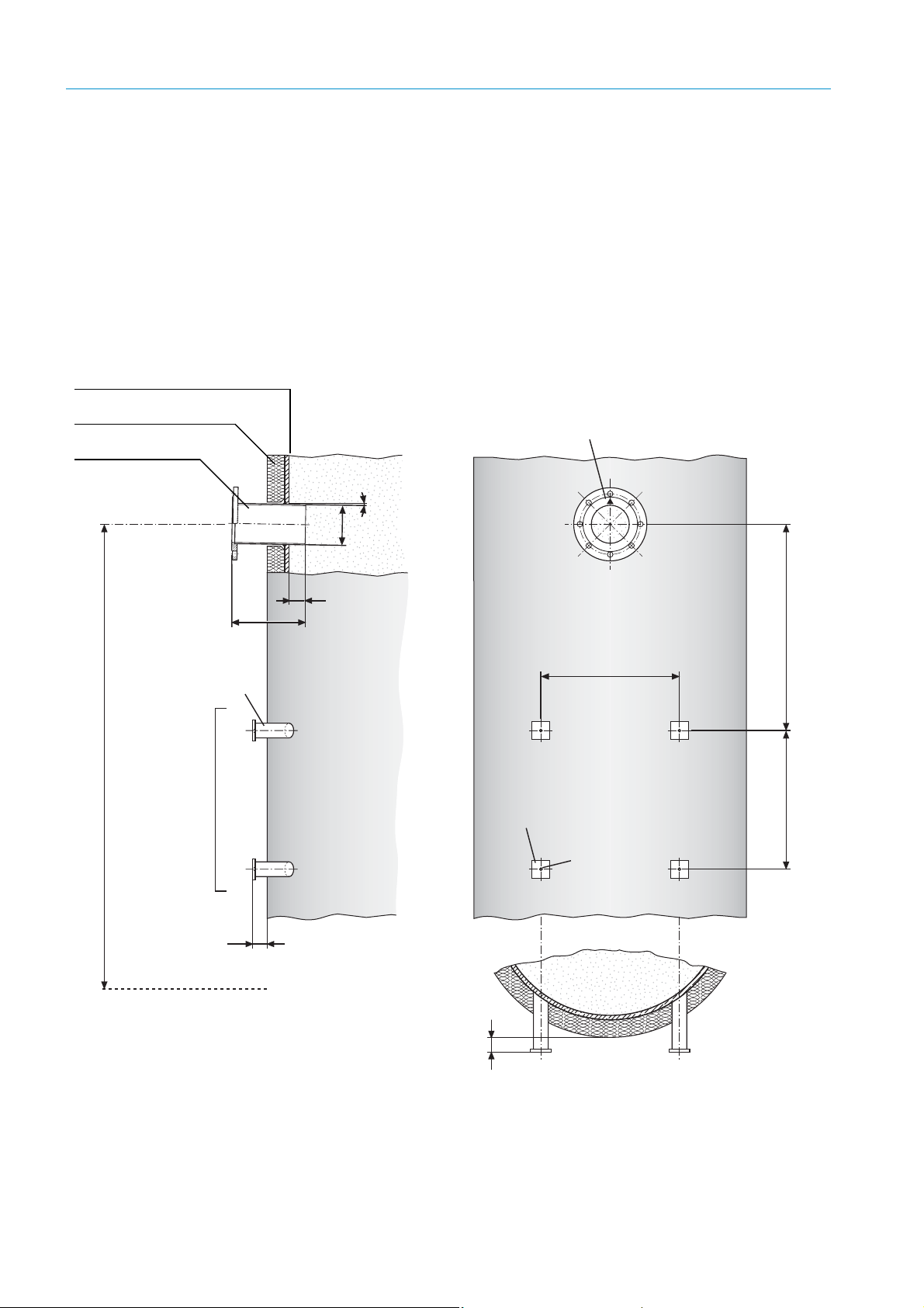
30
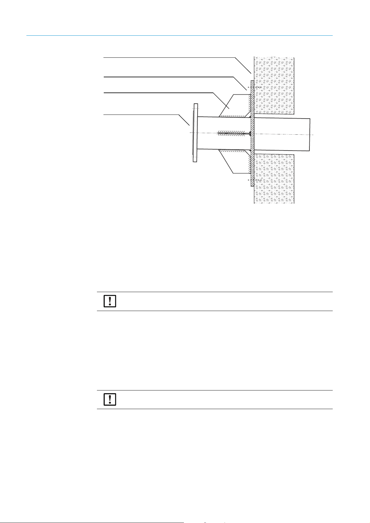
L
50
470
M10
Ø133
1
°
FL. 60x8x60
DIN 174
min. 700
Stahlrohr
50 x 5
DIN 2391
▴
: Markierung für Einbaulage
in Strömungsrichtung zeigend
Befestigung der Spüllufteinheit
1,3 – 1,5 m
50 mm Überstand bei kreisförmigem Kanalquerschnitt
Arbeitsbühne/Plattform
470
Duct wall (steel)
Duct insulation
Flange with tube,
standard: L = 240 mm
▴ : Marking for fitting position,
pointing in flow direction
Steel pipe
50 x 5
DIN 2391
Purge air unit fastening
Platform
50 mm protrusion for circular duct cross-section
3.3 Initial onsite installation
The following work can be carried out by the customer's technicians. Requirement: The
project planning checklist has been processed beforehand.
3.3.1 Assembly preparation at the measuring point
This Section describes the welding work on the duct including making fixing elements
onsite.
Already completed? If you have already used the separate document “Product Information and Planning Guide”
to complete the work described here prior to delivery of the device, please check that the
work done corresponds to the following instructions.
26
Fig. 8: Installation recommendation: Mounting flange and purge air unit (duct diameter not representative)
8009389/YN39/V3-0/2015-08| SICKOPERATING INSTRUCTIONS|GM35
Subject to change without notice
Page 27
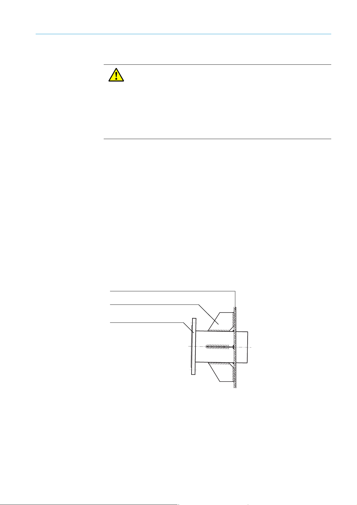
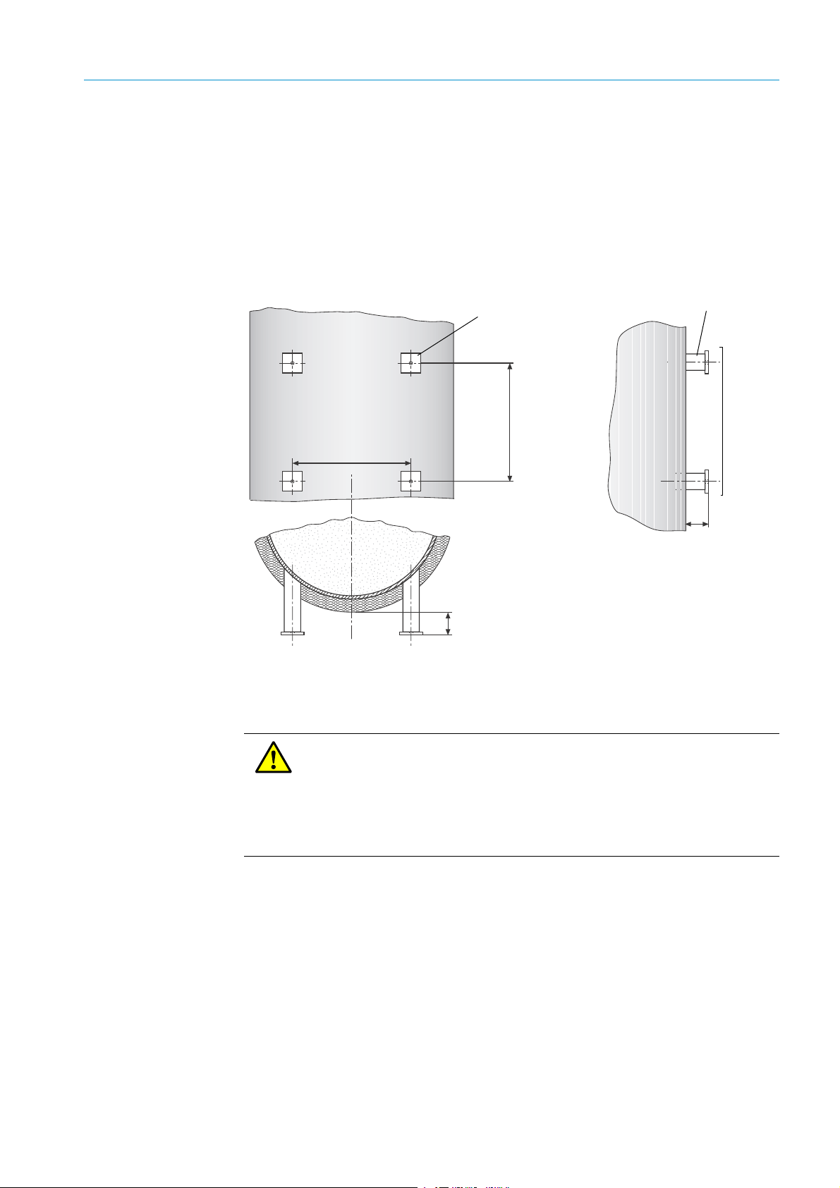
CAUTION: Protective measures at the measuring point
Duct wall (steel)
Reinforcing sheets (onsite)
Flange with tube
▸ Always shut down the installation before any work on the duct!
▸ Secure parts to be separated with, for example, wire binding, to prevent
damage by falling objects.
▸ Take appropriate protective measures against hot, explosive gases or toxic
gases that could possibly escape from the duct.
▸ Always take all necessary safety precautions during welding work to prevent
explosions or fire in the duct atmosphere and on the duct insulation.
▸ If necessary, seal off the mounting flange with a cover securely until device
assembly (e.g. for overpressure in duct).
3.3.2 Uncovering the duct
▸ If necessary, remove approx. 800 x 1500 mm (W x H) of the duct insulation to be able to
access the duct during subsequent work.
▸ Keep the insulation material removed for later refitting resp. provide new suitable
insulation material.
3.3.3 Installing the flange with tube
PROJECT PLANNING INFORMATION
Notes on flange
installation
• Standard flanges and special versions
SICK delivers one flange with tube with 240 mm total length and 125 mm inner diameter
as standard. A version with 500 mm total length is available for installation locations with
thicker insulation or for stone stacks.
Special versions can be manufactured on request. Onsite flanges, including ANSI
flanges, can also be used.
• Reinforcement with junction plates recommended
Due to the weight of the GM35 sender/receiver unit, it is recommended to reinforce the
flange tube onsite with junction plates.
8009389/YN39/V3-0/2015-08| SICK OPERATING INSTRUCTIONS|GM35
Subject to change without notice
Fig. 9: Reinforcing with junction plates
• Gas-carrying duct made of brick/concrete
An additional retaining plate with suitable opening should be manufactured for ducts not
made of steel and the flange with tube then welded into the opening.
27
Page 28
PROJECT PLANNING INFORMATION
Wall of the gas-carrying duct (brick/concrete)
Retaining plate (onsite)
Flange with tube
(example: Version 500 mm long)
Reinforcement plates (recommended, onsite)
Fig. 10: Installation on a brick/concrete duct
• Using the angle flange for zero point measurement
To use the angle flange (Part No. 2 017 833) for zero point measurement, make sure the
SR-unit with mounted measuring probe can be attached without hindrance to the duct
using the angle flange. Avoid obstacles in the vicinity of the flange with tube, such as, for
example, protruding duct insulation. A longer flange with tube or an angle flange with
spacer (to be provided by the customer) may be required to ensure the distance from the
duct wall is sufficient.
3.3.3.1 Installation steps: Fitting the flange with tube
1 For brick/concrete ducts: Cut the duct opening approx. 2 cm larger than the flange tube
outer diameter.
2 Cut an opening matching the outer flange tube diameter (standard Ø
the duct wall resp. retainer plate.
3 Position the flange tube so that the marking points exactly in gas flow direction
(compare
plate (approx. 1°, see page 26) to prevent condensate deposits later between tube and
probe. Affix in the fitting position.
4 Weld the flange tube on.
5 Weld on with junction plates as reinforcement when possible; see
NOTICE: Observe the safety information on page 26 at all times!
= 133 mm) out of
a
page 26). Incline the tube slightly downwards in the duct resp. on the retainer
page 27 or page 28.
28
NOTICE: Brick/concrete ducts: Anchor the holding plate with the welded flange
with tube to the duct as shown on
page 28.
8009389/YN39/V3-0/2015-08| SICKOPERATING INSTRUCTIONS|GM35
Subject to change without notice
Page 29
3.3.4 Installation preparation for the purge air unit
Steel pipe 50 x 5
DIN 2391
Purge air unit fastening
50 mm protrusion for circular duct cross-section
Flange 60 x 8 60
DIN 174
PROJECT PLANNING INFORMATION
Is a purge air unit to
be used?
This step is only relevant for device configurations containing a purge air unit. GM35
configurations with GPP measuring probes do not require purge air.
1 Make brackets from steel pipes (e.g. 50 x 5) with flanges (e.g. FL 60 x 8 x 60) for the
four fixing points of the purge air unit ; bore M10 threads in the mounting holes.
2 Weld the brackets on as shown when using steel ducts.
For stone stacks, fit retainer plates to each steel pipe or use a different, suitable mounting
for the purge air unit.
3.3.5 Duct insulation
3
Fitting recommendation for purge air units (duct diameter not representative)
▸ Refit the thermal duct insulation; reinforce the insulation when necessary.
CAUTION: Device failure due to high ambient temperatures
The SR-unit of the GM35 is designed for a maximum ambient temperature of
+55 °C. Radiant heat on the enclosure surface can, under certain
circumstances, lead to temperatures higher than the measured air
temperature.
▸ Therefore, design insulation and radiation shielding so that temperature
limits are reliably maintained.
8009389/YN39/V3-0/2015-08| SICK OPERATING INSTRUCTIONS|GM35
Subject to change without notice
29
Page 30
PROJECT PLANNING INFORMATION
3.3.6 Installation preparation for the evaluation unit
Requirements The installation location for the evaluation unit was determined during project planning.
The maximum total cable length of all CAN bus connections in the GM35 measuring
system of 1000 m was taken into account, bearing in mind that the closer the device is to
the measuring point, the easier it is to use.
Installation location preparation
The evaluation unit is fitted with clips which enable it to be mounted easily using 4 screws,
even on an uneven surface.
▸ Based on the dimension drawing of the EvU according to
space is available at the planned installation location to fit and wire the EvU as well as to
pivot the enclosure door.
▸ Drill suitable openings as assembly points as required.
3.4 Preparations for electrical installation
The onsite supply and signal cables are laid beforehand to facilitate subsequent
installation and start-up of the GM35 system components. Suitable cable ducts or
conduits are installed for the prefabricated cables and delivered with the GM35 system
(marked with * in
“Cable routing diagram”).
page 135, make sure sufficient
The prepared cables are connected to the devices during installation or start-up by suitably
qualified personnel or by SICK Customer Service.
Already completed? If you have already used the separate document “Product Information and Planning Guide”
to complete the work described here prior to delivery of the device, please check that the
work done corresponds to the following instructions.
3.5 Electrical protection
Evaluation units of GM35, Power Supply 24 V; SCU I/O
• Insulation: Protection class 1 in accordance with EN 61140
• Insulation coordination: Overvoltage category II in accordance with EN61010-1
• Contamination: Degree of contamination II in accordance with DIN EN 61010-1
3.6 Specifications on electric isolation of the EvU
Connections SCU I/O
Relay contact <-> PE 860 V AC
Relay contact <-> relay contact 860 V AC
Relay contact <-> actuation 1376 V AC
Table 3: Characteristic data for electric isolation
3.6.1 Electrical installation safety information
WARNING: Hazard by voltage.
▸ Only allow an authorized electrician to work on the electric system.
▸ Observe the relevant safety regulations during all installation work.
▸ Take suitable protective measures against local risks and those arising
from the plant.
30
8009389/YN39/V3-0/2015-08| SICKOPERATING INSTRUCTIONS|GM35
Subject to change without notice
Page 31

PROJECT PLANNING INFORMATION
WARNING: Endangerment of electrical safety during installation and
maintenance work when the power supply is not switched off
An electrical accident can occur during installation and maintenance work
when the power supply to the device and/or lines is not switched off using a
disconnector switch/circuit breaker.
▸ Before starting the work, ensure the power supply can be switched off
using a power isolating switch/circuit breaker in accordance with
DINEN61010.
▸ Make sure the disconnector switch is easily accessible.
▸ An additional disconnecting device is mandatory when the power isolating
switch is difficult to access or cannot be accessed when connecting the
equipment after installation.
▸ The power supply may only be activated again after the work or for test
purposes by personnel carrying out the work under consideration of valid
safety regulations.
WARNING: Endangerment of electrical safety through power cable with
incorrect rating
When a removable power cable is used, electrical accidents can occur when
the specifications are not fully observed.
▸ Always observe the exact specifications in the Operating Instructions
(Technical Data Section) when replacing a removable power cable.
CAUTION: Device damage through incorrect or missing grounding.
During installation and maintenance work, it must be ensured that the
protective grounding to the devices and/or lines involved is effective in
accordance with EN 61010-1.
NOTICE: Responsibility for the safety of a system
The safety of the system in which the equipment is integrated is the
responsibility of the person setting up the system.
WARNING: Risk of fire due to hot gas escaping in installations with
overpressure conditions
On installations with overpressure, the purge air hose can be severely
damaged by escaping hot gas and can catch fire depending on the
temperature.
On plants with overpressure as well as gas temperatures over 200°C:
▸ Ensure reverse flow is prevented by fitting a (trip) flap or a valve.
▸ Regularly check the functionality of the reverse flow safeguard.
8009389/YN39/V3-0/2015-08| SICK OPERATING INSTRUCTIONS|GM35
Subject to change without notice
31
Page 32

PROJECT PLANNING INFORMATION
WARNING: Endangerment of electrical safety through heat damage to lines
When planning the lines, take into account that the connection unit can reach
a temperature >60°C due to self-heating at maximum ambient temperature.
▸ Only use lines specified for temperatures >80°C.
3.7 Electrical protection
Evaluation units of GM35, Power Supply 24 V; SCU I/O
• Insulation: Protection class 1 in accordance with EN 61140
• Insulation coordination: Overvoltage category II in accordance with EN61010-1
• Contamination: Degree of contamination II in accordance with DIN EN 61010-1
3.8 Specifications on electric isolation of the EvU
Connections SCU I/O
Relay contact <-> PE 860 V AC
Relay contact <-> relay contact 860 V AC
Relay contact <-> actuation 1376 V AC
Table 4: Characteristic data for electric isolation
32
8009389/YN39/V3-0/2015-08| SICKOPERATING INSTRUCTIONS|GM35
Subject to change without notice
Page 33

3.9 Laying connection lines
maintcalpardiag
GM 35
Evaluation Unit
CO
CO
2
H2O
mg/
m
3
236
Ref. conditions
Hum: wet
Measuring
Operation
Service
Warnin
Malfunction
Power supply
(230/115 V AC) *
4m, 3 x 1.5mm
2
SR-unit
Measuring probe (example: GMP)
CAN *
1m
Evaluation unit
CAN bus extension, ready
for connection, 15 m
CAN bus cable (stan-
dard), 4 m *
Terminal box (option)
Standard cable
connection
Cable connection,
option
Cable in scope of
delivery
*
Prefabricated with plug-in
connector(s)
Purge air unit SLV4
(Standard for GMP
measuring probe)
Power supply 4 x
1.5 mm
2
Signal cable for:
• Filter monitoring of the SLV 4 – 2 x 0.6 mm
2
,
on pressure controller with flat pin bushings
6.3 x 0.8 mm (DIN 46247)
• Pressure connection
Functional
earth 2.5 mm
2
Power supply (230/115 V AC)
3 x 0.75 mm
2
3 binary inputs 6 x 0.5 mm
2
3 analog inputs 6 x 0.5 mm
2
3 binary outputs 6 x 0.5 mm
2
3 analog outputs 6 x 0.5 mm
2
to lengthen the CAN bus
connection with a cable
(1 x 2x 0.5mm
2
, twisted
pair, shielded) provided by
the customer
Cable connection for
optional terminal box
PROJECT PLANNING INFORMATION
8009389/YN39/V3-0/2015-08| SICK OPERATING INSTRUCTIONS|GM35
Subject to change without notice
Fig. 11: Cable routing diagram
33
Page 34

PROJECT PLANNING INFORMATION
3.9.1 CAN bus wiring
Standard cables
An installation location in the vicinity of the measuring point is generally selected for the
EvU so that the 4 m CAN bus cable delivered is sufficient for cabling without additional
installation effort. CAN bus extensions, ready for connection with plug-in connectors, are
also available in various lengths (
Installation away from the evaluation unit
A 6-pole terminal box can be supplied when the EvU is to be located some distance from
the SR-unit. This is then connected to the SR-unit using the 4 m CAN bus cable delivered
with the measuring system. A customer cable suitable for CAN bus applications, 6-pole
cable (twisted pair wires and shielded), then leads to the EvU. The total length of the CAN
bus connections, including the one to the reflector, may be up to 1000 meters. When
performing maintenance or service, it must be possible to deinstall the EvU temporarily
and connect it directly to the SR-unit at the measuring point.
Laying the cables
▸ Provide adequate cable lengths at the connection points.
▸ Whenever possible, do not lay power supply cables immediately next to signal cables.
▸ Protect open ends of preinstalled cables against weather effects until device
installation.
▸ Install separate power supply cables and circuit breakers for:
– GM35 SR-unit (via connection unit or terminal strip in control cabinet)
– Purge air units; additional motor circuit breakers and optional protective phase failure
switches.
– Evaluation unit
see “Connection cables”).
CAUTION: Risk of device damage due to switching off the voltage supply
unintentionally
The purge air supply may not be switched off while the measuring system is on
the gas duct.
▸ Attach clearly visible warnings against accidental switching-off to all
switching devices where the purge air supply can be switched off.
WARNING: Risk of fire due to hot gas escaping in installations with
overpressure conditions
On installations with overpressure, the purge air hose can be severely
damaged by escaping hot gas and can catch fire depending on the
temperature.
On plants with overpressure as well as gas temperatures over 200°C:
▸ Ensure reverse flow is prevented by fitting a (trip) flap or a valve.
▸ Regularly check the functionality of the reverse flow safeguard.
▸ Install easily accessible cable ducts or empty tubes for prefabricated cables or cables
delivered with the system,
two plug-in connectors ). Approx. 2 m cable lengths each should be available at the
measuring point for later maintenance work on the measuring system when dismounted
from the duct.
see “Cable routing diagram”, page 33 (marked with one or
▸ Lay cables provided by the customer (shown without plug-in connectors) according to
see “Cable routing diagram”, page 33.
34
8009389/YN39/V3-0/2015-08| SICKOPERATING INSTRUCTIONS|GM35
Subject to change without notice
Page 35

PROJECT PLANNING INFORMATION
– The specifications for the lead cross-sections are recommendations whereby cables
for analog and binary signals may differ slightly from these (but not the CAN bus
connections or the power supply cables).
– Start with the system internal connections of the GM35.
Status and signal cables from the EvU to the connection terminals of the customer's
status/signaling equipment can be connected later when required.
8009389/YN39/V3-0/2015-08| SICK OPERATING INSTRUCTIONS|GM35
Subject to change without notice
35
Page 36

INSTALLATION
4 Installation
This Section describes assembling and installing the GM35 measuring system prior to the
actual start-up. It is assumed that the onsite preinstallation has been completed, see “Proj-
ect Planning Information”, page 22
4.1 Preparations
4.1.1 Checking the scope of delivery
▸ Check the delivery against the associated delivery note and make sure the complete
measuring system has been delivered as ordered. The typical scope of delivery
comprises the components described in Section
tion”.
▸ Inspect the delivery for visible external transport damage or damage to the packing.
▸ Check the specifications on mains voltage and frequency on the type plates of the
GM35 components match the installation conditions, delivery note and the order.
4.1.2 Installation prerequisites
The following prerequisites are applicable for the work described in the following:
.
“Preparations for electrical installa-
▸ Plan safe usage/application within the limits defined in
and Spare Parts”, page 128.
“Technical Data, Consumables
▸ Compliance with the specifications made during project planning (according to “Project
Planning Checklist”, page 23) and correct performance of onsite preinstallation
according to
“Initial onsite installation”, page 26.
WARNING: Endangerment of electrical safety during installation and
maintenance work when the power supply is not switched off
An electrical accident can occur during installation and maintenance work
when the power supply to the device and/or lines is not switched off using a
disconnector switch/circuit breaker.
▸ Before starting the work, ensure the power supply can be switched off
using a power isolating switch/circuit breaker in accordance with
DIN EN 61010.
▸ Make sure the disconnector switch is easily accessible.
▸ An additional disconnecting device is mandatory when the power isolating
switch is difficult to access or cannot be accessed when connecting the
equipment after installation.
WARNING: The power supply may only be activated again after the work or for
test purposes by personnel carrying out the work under consideration of valid
safety regulations.
36
8009389/YN39/V3-0/2015-08| SICKOPERATING INSTRUCTIONS|GM35
Subject to change without notice
Page 37

4.2 Fitting system components
Assembly holes
Base plate
Y-distributor
4.2.1 Information on the SR-unit and measuring probe
The GM35 SR-unit and measuring probe are first fitted on the duct during start-up (
“Connecting the System Control Unit - SCU”) because these components first require an
adjustment away from the gas-carrying duct. To avoid problems during start-up, the SR-unit
and measuring probe must be stored in a dry place free from dust, preferably at room
temperature, until start-up.
CAUTION: Damage to the measuring system due to assembly of the SR-unit
and/or measuring probe before start-up
Unfavorable ambient conditions or atmosphere in the measuring duct can
damage the measuring system which prevents start-up. Apart from that, there
is a health risk when opening the duct depending on the pressure, gas
temperature and composition in the sample gas duct.
4.2.2 Installing the purge air unit
Note A dimension drawing can be seen in “Purge air unit dimension drawing”, page 137.
Brackets should have M8 threadholes or M8 separator bolts for fastening to the base
plate.
INSTALLATION
see
Fig. 12: Installing the purge air unit
1 Secure the base plate for the purge air unit using 4 M10 x 45 screws on the brackets
provided by the customer.
2 Cut the purge air hose to a suitable length for the respective purge air fixture, attach it to
the open outlet of the Y-distributor and secure it with a hose clamp.
3 Close off the hose ends when the purge air unit is not going to be used for a longer
period.
If the purge air unit is not connected electrically immediately:
4 For outdoor installations, fit the weatherproof cover planned during project planning
(optional in scope of delivery).
5 Protect the open end of the purge air hose from humidity or contamination until SR-unit
start-up.
8009389/YN39/V3-0/2015-08| SICK OPERATING INSTRUCTIONS|GM35
Subject to change without notice
37
Page 38

INSTALLATION
Mounting holes
4.2.3 Terminal box (option)
▸ Install the terminal box in the vicinity of the measuring point.
– Secure the enclosure on the two mounting holes (∅ 5 mm).
▸ The cable length available from the terminal box to the SR-unit is 4 m.Take the empty
conduits laid for the prefabricated cables during onsite preinstallation into account.
Fig. 13: Fitting the terminal box
38
8009389/YN39/V3-0/2015-08| SICKOPERATING INSTRUCTIONS|GM35
Subject to change without notice
Page 39

4.3 Installing the evaluation unit
4 mounting holes
∅ 8mm
Mounting surface
Fastening brackets
The fitting location for the evaluation unit was defined during project planning (see “Project
Planning Checklist”, page 23) and prepared during onsite preinstallation as required.
▸ Make sure the CAN bus connection to the SR-unit selected during project planning is
usable at the planned installation location. The CAN bus connection cable delivered as
standard is 4 m long and serves to connect the evaluation unit directly at the measuring
point.
▸ Ensure easy access without problems. In particular, make sure the swivel door of the
evaluation unit can be opened without hindrance after fitting.
4.3.1 Installing the evaluation unit – sheet metal enclosure version
▸ Make ∅7.2 mm (for M8) mounting holes at the installation location according to the
Drilling plan.
▸ Attach the evaluation unit at the installation location using the 4 planned fastening
brackets with suitable screws.
INSTALLATION
8009389/YN39/V3-0/2015-08| SICK OPERATING INSTRUCTIONS|GM35
Subject to change without notice
Fig. 14: Installing the evaluation unit (sheet metal enclosure version)
39
Page 40

INSTALLATION
117.5
330
235
Swivel door
Mounting holes
∅ 7mm
Mounting surface
The mounting holes
are accessible
when the swivel door is
open.
Mounting holes
∅ 7mm
1.
2.
4.3.2 Installing the evaluation unit – cast enclosure version
1 Make ∅7.2 mm (for M8) mounting holes at the installation location according to the
Drilling plan.
40
Fig. 15: Mounting holes layout (Drilling plan) to fit the EvU (cast enclosure)
2 Open the enclosure door with a control cabinet key and swivel open.
3 Attach the evaluation unit at the installation location using the 3 planned mounting
holes with suitable screws (M8 x 20).
Fig. 16: Fitting the evaluation unit (cast enclosure)
4 Close and lock the door again.
8009389/YN39/V3-0/2015-08| SICKOPERATING INSTRUCTIONS|GM35
Subject to change without notice
Page 41

4.4 Electrical connection of system components
<
<
>>
=
=
<
<
=
=
>
>
7,333
<=>
=><7,
7,333
<=>
=><7,
Low-pressure monitor
connection
SLV
UW
Terminal box
blower motor
Delta connection
Star connection
Motor circuit
breaker
NO contact, switches at
approx. 35 hPa
underpressure
Onsite preparation for electrical installation has been described in “Preparations for electri-
cal installation”, page 30. The cables laid as described there are now connected to the sys-
tem components.
WARNING: Observe safety information as well as relevant safety regulations!
During all work on electrical equipment, disconnect such equipment from the
mains, check that the equipment is potential free and make sure no third
person can switch the equipment back on again without authorization.
4.4.1 Electrical connection for the purge air unit
The technical data of the standard purge air unit are contained in
sumables and Spare Parts”, page 128.
INSTALLATION
“Technical Data, Con-
Fig. 17: Purge air unit: Electrical connections for blower motor and low-pressure monitor
8009389/YN39/V3-0/2015-08| SICK OPERATING INSTRUCTIONS|GM35
Subject to change without notice
41
Page 42

INSTALLATION
1 Check the type plate to determine whether the connection values of the purge air unit
delivered match the plant conditions.
2 Connect the power supply cable in the terminal box of the purge air unit as shown in
“Purge air unit: Electrical connections for blower motor and low-pressure monitor”. Note
that any differing connection diagrams supplied with the terminal box are valid.
3 Remove the seal at the end of the purge air hose (if present) to check whether the hose
functions correctly.
4 Switch the power supply on.
5 Does the motor rotation direction match the following attributes?
– Arrow marking on the motor cover
– Arrows on the pump housing
– A strong airstream must flow out of the purge air hose.
6 If the rotation direction is wrong:
▸ Switch the power supply off.
▸ Switch two phased wires in the supply line in the terminal box (e.g. between U1 and
V1).
▸ Switch the power supply back on.
▸ Make sure the rotation direction is now correct.
CAUTION: Possible damage when the purge air blower rotates in the wrong
direction
Rotation in the wrong direction suctions sample gas out of the duct when the
measuring system is installed. The following damage can incur when this is not
prevented quickly:
● Contamination and overheating of the measuring system and the purge air
unit.
● Health risks for persons in the vicinity of the purge air unit (depending on
sample gas composition and/or temperature).
7 Set the motor circuit breakers in accordance with the connected loads of the purge air
blower and check for correct function.
8 Connect the low-pressure monitor for filter monitoring to the signal line prepared onsite.
Note The switching signal of the low-pressure monitor is evaluated by the customer.
▸ Check the low-pressure monitor function and the connected signal function:
Cover the suction opening partially for a short time when the purge air unit is running.
Use wide cardboard strips or something similar that cannot be sucked in or contaminate
the filter.
▸ Switch the purge air unit power supply off until measuring system start-up.
For installations outdoors or in unprotected conditions:
▸ Protect the opening of the purge air hose against moisture and contamination until the
measuring system is put into operation; refit any dummy plugs removed beforehand.
▸ Fit the weatherproof cover.
4.4.2 CAN bus wiring options
As already described in the project planning on
for wiring the CAN bus connection between SR-unit and evaluation unit:
• Standard cable, 4 m, prefabricated
• Standard cable, 4 m, as well as additional prefabricated 15 m CAN bus extension cable
• Terminal box with prefabricated 4 m long cable to SR-unit; a cable provided by the
customer is used to connect to the evaluation unit.
Information on selecting a suitable type of wiring can be found under
wiring”, page 25.
page 30, the following options are available
“Options for CAN bus
42
8009389/YN39/V3-0/2015-08| SICKOPERATING INSTRUCTIONS|GM35
Subject to change without notice
Page 43

Wiring in terminal box
WR
NY
`L
NU
IU
^O
*(5/
*(53
*(5.5+
Prefabricated cable
with plug, 4 m long,
to SR-unit
Cable provided by the
customer for the
evaluation unit
INSTALLATION
Fig. 18: Terminal box for CAN bus connection with a cable length between SR-unit and evaluation unit longer than 19 m
Wiring the connections in the terminal box
1 Lead the CAN bus cable provided by the customer through the free screw fitting of the
terminal box.
2 Connect the shield on the screw fitting to the enclosure of the terminal box.
3 Connect the wires to the terminal strip as shown on
page 43; make sure a twisted wire
pair is used for CAN-H and CAN-L.
8009389/YN39/V3-0/2015-08| SICK OPERATING INSTRUCTIONS|GM35
Subject to change without notice
43
Page 44

INSTALLATION
+ – + – + –
+ – + – + –
+ –
+ – + –
PE
N
L1
PE N L1
V 42+
H NAC
L NAC
V 42+
H NAC
L NAC
CAN GND
CAN H
CAN L
CAN GND
+– +–+–
115/230 V AC;
50/60 Hz
(3 x 1.5
2
)
+– +–+–
12
12 3
Power
+5V +24V
Power CAN
+24V
+ – H L GND
Digital in
CAN2
Terminator
Analog in
0.. 20mA
100 100 100
40..60Hz
230V
or
115V
AO1 AO2 AO3DI1 DI2 DI3 AI1 AI2 AI3
Sensor
DO1 DO2 DO3
Digital out
AC/DC 48V 30VA 1A
Analog out
0.. 20mA
Sensor
CAN2
Fuse 2.5 AT 250V
PE N L1
Tp
Enter meas
diag par cal maint
Operation
Service
Warning
Malfunction
GM 35
Evaluation Unit
RS 232
Plug this bridge for 115 V or 120 V voltage supply.
48 V AC/DC; 60 VA,
1 A (6 x 0.752)
Relay outputs
0...20 mA (6 x 0.75
2
)
Analog outputs
0...20 mA (6 x 0.52)
Analog inputs
Failure
1)
Maintenance request
2)
Function control
2)
Check cycle
Free assignment
Jumper not connected
(not activated)
Connections circuit board
Cast-metal enclosure shown
1)
NC contact
2)
NO contact
Cable (twisted, shielded) to
SR-unit or terminal box
Cable (twisted, shielded)
to SCU
RS232 connection
CAN2
terminator
Jumper connected
(activated)
4.4.3 Electrical connection of the evaluation unit
Laying cables to the evaluation unit and the cable specifications have already been
described in
ing diagram”, page 33.
“Preparations for electrical installation”, page 30, in particular in “Cable rout-
Fig. 19: Connections on the evaluation unit (cabling provided by the customer)
44
8009389/YN39/V3-0/2015-08| SICKOPERATING INSTRUCTIONS|GM35
Subject to change without notice
Page 45

INSTALLATION
Make connections
1 Open enclosure door of evaluation unit.
▸ Lead the signal cable for inputs and outputs through the PG screw fittings on the EvU
enclosure floor and wire according to
vided by the customer)”, page 44.
Observe connection values for power supply!
The evaluation unit is configured to 230 V AC on delivery.
“Connections on the evaluation unit (cabling pro-
▸ Plug the respective bridges for 115 resp. 120 V AC as shown on the
connection plate of the evaluation unit.
▸ Make sure the power supply has been installed (
the evaluation unit”
national specifications) and that the power is switched off.
Fig. 20: EvU power connection
) in accordance with the specifications (observe
“Electrical connection of
GM35 SR-unit or terminal box connection:
▸ If the customer supplied CAN cable is used, connect the wires to terminal strip “Sensor”,
see page 44. Do not connect +24 V and GND (earth).
Connection to the SCU (System Control Unit):
▸ If the customer supplied CAN cable is used, connect the wires to terminal strip “CAN2”,
see page 44.
▸ Activate the terminating resistor of the CAN bus when the EvU is connected to the start
or end of the CAN bus, see page 44:
▸ Connect the jumper for the CAN2 terminator.
▸ Deactivate the terminating resistor for the CAN bus when the EvU is not connected to
the start or the end of the CAN bus, see page 44:
>>>
No jumper may be connected to the CAN2 terminator.
8009389/YN39/V3-0/2015-08| SICK OPERATING INSTRUCTIONS|GM35
Subject to change without notice
45
Page 46

INSTALLATION
3
4
2
1
CAN cable
shielding
PG screw fitting on the
evaluation unit
CAN bus cable
PG screw fitting
used on the EvU
See steps 1 to 4 below.
Fig. 21: Attaching the CAN bus cable to the evaluation unit
46
8009389/YN39/V3-0/2015-08| SICKOPERATING INSTRUCTIONS|GM35
Subject to change without notice
Page 47

5 Handling the Evaluation Unit
GM 35
Evaluation Unit
CO
CO
2
H2O
mg/
m
3
236
Ref. conditions
Hum: wet
Operation
Service
Warning
Malfunction
GM 35
Evaluation Unit
CO
CO
2
H2O
mg/
m
3
236
Ref. conditions
Hum: wet
Enter meas
diag par cal maint
Measuring
Operation
Service
Warning
Malfunction
GM 35
Evaluation Unit
CO
CO
2
H2O
mg/
m
3
236
Ref. conditions
Hum: wet
Enter meas
diag par cal maint
Measuring
Measuring
Enter meas
maintcalpardiag
Operation
Service
Warning
Malfunction
Graphic display for measured value
display and navigation
Key pad for navigation and
entering data
Key pad for menu selection
5.1 User qualifications
This Section describes how to operate the GM35 measuring system with the evaluation
unit (EvU). The evaluation unit is available with either a sheet metal enclosure (protection
class IP 65) or a cast enclosure (protection class IP 67). The work described in this Section
can be carried out by qualified customer operating personnel. Setting parameters does
however demand comprehensive knowledge of the measuring system, measuring
technology and specific measuring task.
5.2 Operating elements
The evaluation unit of the analysis system serves to display, enter and set parameters and
control functions on the system. The operator panel with the display, status indicators and
key pad is accessible when the enclosure door is opened.
HANDLING THE EVALUATION UNIT
8009389/YN39/V3-0/2015-08| SICK OPERATING INSTRUCTIONS|GM35
Subject to change without notice
Fig. 22: Display and operating elements on the evaluation unit
Navigate, select, scroll or edit menu items, variables, units or
Arrow buttons
digits.
Enter Executes the selected menu contents or commands.
Display in
Measuring
mode
Displays all current measured values (temperature values or CO
concentration);
Displays all calculated values, e.g. CO
LEDs
● Operation
● Service
● Warning
● Malfunction
Measuring
Service mode
Warning messages, see Diagnosis mode (diag)
Device malfunction, error message, see Diagnosis mode (diag)
dry.
2
47
Page 48

HANDLING THE EVALUATION UNIT
5.2.1 Function buttons and menu overview
Measuring
● CO2875 ppm
● Reference
conditions
Diagnosis
● Malfunction
● Warning
● Sensor Values
● Check values
● Optical
alignment
Parameters
● Parametrization
● Device
● Service
Calibration
● Check cycle
● Zero point
● Box Measuring
cal
● Manual Test
● Press. sensor
adjust.
● Temp. sensor
adjust.
Maintenance
● Maintenance
mode
● Optical
alignment
● Tests
● Reset System
● Reset
Parameter
Table 5: Function buttons and menu overview
Current measured value of the selected measured variable;
the display shows the measured values of the current
measured variables such as CO
, H2O, temperature and
2
pressure when selected
Shows the parameterized reference conditions (humidity,
temperature and pressure)
Current error messages (plain-text)
Current warning messages (plain-text)
Displays diagnosis values
Displays check values of the measured component (CO or
N2O, CO2, H2O)
Displays the optical alignment
Sets/displays system component parameters
Displays the serial number (evaluation unit) and software
version (system components)
Displays calibration coefficients of the measuring
components
For test purposes, e.g., after maintenance work on the
analyzer
Zero point determination, e,g,, for startup procedures
Starts filter box measurement (control filter, test gas)
Manual test by feeding test gases
Starts the adjustment procedure for the pressure sensor
Starts the adjustment procedure for the temperature sensor
Activates maintenance mode
Optical alignment of the SR-unit and reflector
Tests analog and relay outputs
System cold start
Resets parameters to the factory settings
48
8009389/YN39/V3-0/2015-08| SICKOPERATING INSTRUCTIONS|GM35
Subject to change without notice
Page 49

5.2.2 Display contents
meas
ppm
2875
Measuring
CO
CO2
H2O
Ref. conditions
Hum: wet
• The header line shows the selected operating mode (e.g. parameter settings) or the
• Four lines for submenus, plain-text messages or settings (values)
• Function line:
5.2.3 Menu structure
HANDLING THE EVALUATION UNIT
Zero gas
menu items just selected during navigation.
← back To return to a higher level menu, use the Arrow
← button
save: Enter To activate menu items or confirm entries, use the Enter button
select To select a value, use the Enter button
↑ (↓) When selecting a variable for which a number is to be entered,
use the Arrow ↑ (↓) buttons to select the value for each digit
Password When prompted for the password, enter 1 2 3 4 with ↑ (↓).
5.2.3.1 Menu structure Measuring Mode
Fig. 23: Menu Operation
Measuring
8009389/YN39/V3-0/2015-08| SICK OPERATING INSTRUCTIONS|GM35
Subject to change without notice
49
Page 50

HANDLING THE EVALUATION UNIT
Malfunction
Warning
Sensor Values
Check Values
GM 35 general
CO / N2O
H2O
Probe
CO / N2O
CO2
H2O
Adjust Probe
Cross Duct OH
Cross Duct Refl
¨ back¨ back
Nullabgleich
Nullabgleich
Enter
cal
Check Cycle
Check cycle
Start Check cycle
Procedure successful
Zero Adjust
Zero Adjust CO
Box Measuring
Manual Test
Box Measuring
Manual Test ZERO
Zero gas
CO, CO2
Zero gasCO:
3 ppm
CO2: 0.9 % Vol
H2O: 0.4 % Vol
Start Meas. Grid
Start Meas. Gas
5.2.3.2 Menu structure Diagnosis
Menu Diagnosis
Diagnosis
Plain-text messages,
see page 121.
Plain-text messages,
see page 124.
Current monitoring values of the
sensors (amplifier settings,
internal temperature controls,
etc.)
Cross-Duct version:
● Sender/receiver unit (OH)
Reflector
5.2.3.3 Menu structure Calibration
Fig. 24: Menu Calibration
Check values
Displays the optical alignment of
the SR-unit and reflector in
Measuring mode.
Calibration
Check cycle for test purposes,
for example, after maintenance
work
Zero adjust with ambient air,
e.g., during start-up
Filter box measurement for
- control filter (H2O channel,
CO2 for high concentrations).
– test gas (CO, N2O, up to
15 Vol% CO2).
Manual test (CO, N2O, CO2,
H2O),
e.g. with zero gas
Adjustment of device-internal
pressure and temperature
measurement to reference
measurements
50
8009389/YN39/V3-0/2015-08| SICKOPERATING INSTRUCTIONS|GM35
Subject to change without notice
Page 51

5.2.3.4 Menu structure Configuration
←
HANDLING THE EVALUATION UNIT
Table 6: Menu Configuration/Settings
Parametrization
Configuration:
Measuring components:
● CO or N2O, CO2, H2O
● CAN connection (probe or cross-
duct)
Physical Unit:
Unit and reference value settings for
individual gases
Average:
Averaging time settings for the system
Meas.Distance:
Averaging time settings for the system
Temperature:
Temperature setting: Source (probe/
replacement/AI1) and unit (K, °C,
°F)
Pressure:
Pressure setting: Source (probe/
replacement/AI2)
Analog Out:
Analog output settings: Live-zero,
comp. (CO
p - -) display range, cycle output
Analog In:
Analog input settings: e.g., AI1 unit (K,
°C, °F), live-zero (0, 2, 4 mA, readin range)
or N2O, CO
, H2O, O2, T,
2
Check Cycle:
Check cycle interval setting:
0…1440 min
Regress. Funct. CO:
Regression function comp.:
CO2/H2O
Span: 0.50…1.99,
Zero: 0…±9999.9
8009389/YN39/V3-0/2015-08| SICK OPERATING INSTRUCTIONS|GM35
Subject to change without notice
51
Page 52

HANDLING THE EVALUATION UNIT
CO/N2O
←
←
←
←
Configuration, continued:
Device:
Parameter Device: Retrieving the
device information:
– Serial numbers
–Software version
Service area
–Calibration CO/N
–Calibration CO
O
2
2
–Calibration H2O
5.2.3.5 Menu structure Maintenance Mode (Maint)
Table 7: Menu Maintenance
Maintenance mode
Maintenance switch: On/off
Adj.Opt.Align:
– Function for optical alignment of the
SR-unit and reflector
Test of analog outputs
Test of analog inputs
Test of relay outputs
Test of digital inputs
System restart
52
Reset:
Default parameter settings active
8009389/YN39/V3-0/2015-08| SICKOPERATING INSTRUCTIONS|GM35
Subject to change without notice
Page 53

CONNECTING THE SYSTEM CONTROL UNIT - SCU
6 Connecting the System Control Unit - SCU
As an option, the GM35 can be operated and configured via an SCU. The SCU is a control
unit for comfortable, powerful analyzer control. The following actions can be performed on
the GM35 via the SCU:
• Control, parameter setting and display.
• Processing and saving measured values.
• Remote diagnosis.
The SCU is connected to the GM35 evaluation unit via a system bus and is operated via a
touchscreen or a PC with SOPAS software installed.
Further information on the SCU → “SCU” Operating Instructions.
6.1 SCU connection to the GM35
CAUTION: Higher malfunction susceptibility when used in unspecified
ambient conditions
▸ Take all measures possible to protect equipment/module against
dampness, liquids or contamination.
▸ Protect the equipment/module against mechanical or thermal stress.
6.1.1 Electrical connection of the SCU to the GM35
The electrical connection of the SCU to the GM35 is described in “Connection
to the SCU (System Control Unit):”, page 45
6.1.2 Configuring and operating using SOPAS
Operator menus and measured value displays are also available on an external PC via
Ethernet for user comfort (with the engineering tool SOPAS ET).
The SICK Open Portal for Applications and Systems (SOPAS) is a software for
communication with analyzers and sensors.
Access to the GM35 is possible via:
• a direct serial connection (RS232) to the evaluation unit.
• an Ethernet connection via an SCU operating unit to the evaluation unit.
.
8009389/YN39/V3-0/2015-08| SICK OPERATING INSTRUCTIONS|GM35
Subject to change without notice
53
Page 54

CONNECTING THE SYSTEM CONTROL UNIT - SCU
Evaluation Unit
Operation
Service
Warning
Malfunction
GM 35
CO
2
CO
H O
2
Measuring
mg/
m
3
236
Ref. conditions
Hum: wet
SCU operating unit
Ethernet
CAN bus
Ethernet connection
Evaluation Unit
Operation
Service
Warning
Malfunction
GM 35
CO
2
CO
H O
2
Measuring
mg/
m
3
236
Ref. conditions
Hum: wet
GM35 evaluation unit
PC with SOPAS ET
RS232
Serial connection
• PC with SOPAS ET software (page 55).
Fig. 25: GM35 connection options
The menu structure and presentation are principally identical on the SCU or on
the PC with SOPAS ET. The presentation on the SCU is adapted to the smaller
monitor.
For more information on the SOPAS concept, see the Help menu of SOPAS ET.
54
8009389/YN39/V3-0/2015-08| SICKOPERATING INSTRUCTIONS|GM35
Subject to change without notice
Page 55

CONNECTING THE SYSTEM CONTROL UNIT - SCU
6.1.3 Connecting the GM35 evaluation unit via the SCU operating unit
The IP address of the SCU is required to connect to the SCU operating unit and
then to the GM35. When necessary, contact the responsible Network
administrator and request the required IP address.
Connection options
• First connection (initial installation): Install the device description file (SDD; jar),
“Connect to the SCU operating unit:”, page 55.
• Reconnect: Without a saved project, see “Perform a network scan:”, page 56.
• Reconnect: Open a saved project, see “Load the device parameters:”, page 56.
1. Start SOPAS ET.
2. Connect to the SCU operating unit:
▸ Confirm the selection “Connect to new device” in the “Welcome to SOPAS” with OK.
Follow the instructions of the Connection Wizard.
see
▸ In the Connection Wizard, select SCU under “Connect to specific device” and
continue with Next.
▸ Under “Detected devices”, select the desired SCU with the appropriate IP address
and continue with Next.
The selected SCU is added to the project tree.
3. Install the GM35 device description file (SDD; jar) during the initial installation (no
longer necessary afterwards):
▸ Call up the Module Manager in the Tools menu. At the same time, save the project
just generated before closing; acknowledge the message with YES.
▸ In the Module Manager Wizard, select “Install new module” and continue with Next.
▸ Load the GM35 device description file (e.g., from the device CD).
8009389/YN39/V3-0/2015-08| SICK OPERATING INSTRUCTIONS|GM35
Subject to change without notice
55
Page 56

CONNECTING THE SYSTEM CONTROL UNIT - SCU
4. Load the device parameters:
▸ Reopen the project previously saved.
▸ Click the Upload parameters button in “Synchronize device SCU”
5. Perform a network scan:
▸ Click the Network button in the Network Wizard window and then continue with OK
as soon as the scan process has finished.
▸ If the Network Wizard window is not displayed, call up the Network Wizard in the
“View” menu or click the telescope symbol.
▸ After the network scan, click the desired GM35 in the list shown (using the device
name or IP address for identification) and then “Insert” it in the project tree. To do
this, drag the GM35 symbol (e.g., GM35 - 1.5) of the device catalog in the menu tree.
Double-clicking the desired device in the device catalog has the same effect.
56
▸ Project tree with connected SCU and GM35
If an error occurs, e.g.:
• “No sensor found at address ... “:
▸ Switch the sensor on or check the connection, e.g. the Ethernet connection.
• Perform a network scan,
• Devices have been found; the connected GM35 is shown in the device list but is marked
with a red warning symbol “not available”. The device description file has not been
installed.
see “Load the device parameters:”, page 56.
▸
see “Perform a network scan:”, page 56.
▸ Start a new project and then perform step “Perform a network scan:”.
8009389/YN39/V3-0/2015-08| SICKOPERATING INSTRUCTIONS|GM35
Subject to change without notice
Page 57

CONNECTING THE SYSTEM CONTROL UNIT - SCU
▸ If this is not successful, check the network configuration and set the following
standard values.
▸ To do this, click the “Network Configuration” button and then the “Advanced” button
in the window that appears, and then enter the parameters as shown.
▸ Perform a new network scan and follow the instructions from step “Perform a network
.
scan:”
6.1.4 Direct serial connection to the GM35 evaluation unit
Use a serial interface cable (RS232) with a plug (Sub-D, 9-pole) and a socket
to connect the GM35 evaluation unit to a PC/laptop.
▸ Connecting the PC with SOPAS ET directly to the GM35 evaluation unit via a serial
interface cable:
▸ Connect the interface cable to the Sub-D socket of the EvU (
evaluation unit (cabling provided by the customer)”, page 44) and to the Sub-D plug
of the PC.
▸ Use the connection options according to “Connecting the GM35 evaluation unit via the
SCU operating unit”, page 55 onwards:
1. Start SOPAS
2. Connect to the device
▸ Confirm the selection “Connect to new device” in the “Welcome to SOPAS” with OK.
Follow the instructions of the Connection Wizard.
“Connections on the
8009389/YN39/V3-0/2015-08| SICK OPERATING INSTRUCTIONS|GM35
Subject to change without notice
57
Page 58

CONNECTING THE SYSTEM CONTROL UNIT - SCU
▸ In the Connection Wizard, select GM35 under “Connect to specific device” and
continue with Next
▸ Select the GM35 under “Devices found” and continue with Next.
▸ Select “Standard Protocol” under interface selection.
58
▸ Check the protocol settings and adapt when necessary:
8009389/YN39/V3-0/2015-08| SICKOPERATING INSTRUCTIONS|GM35
Subject to change without notice
Page 59

CONNECTING THE SYSTEM CONTROL UNIT - SCU
– Click on “Configure interface” and check the following settings, and adapt when
necessary.
– Continue with “OK”.
▸ Continue the Connection Wizard with Next
The selected GM35 is added to the project tree.
If an error occurs, see
6.1.5 Changing the user level
1. Menu: /Tools/Login
2. In UserLevel dialog window: Click Authorized Client.
Fig. 26: User level
3. Enter password:
User level Password
Authorized Client HIDE
Service GM35SERVICE
[1] Upper case mandatory
page 56.
[1]
*)
4. “Login”
The current user level in SOPAS ET is shown in the bottom left corner.
8009389/YN39/V3-0/2015-08| SICK OPERATING INSTRUCTIONS|GM35
Subject to change without notice
59
Page 60

CONNECTING THE SYSTEM CONTROL UNIT - SCU
6.1.6 Menu overview (menu tree)
Fig. 27: GM35 menu tree
6.1.7 Measured values
Menu GM35/Measured values
60
Fig. 28: Menu: Measured values and Ref. conditions
8009389/YN39/V3-0/2015-08| SICKOPERATING INSTRUCTIONS|GM35
Subject to change without notice
Page 61

This menu shows:
• Measuring operation of the analyzer
• Current measured values and reference conditions
6.1.8 Menu Parameter
Menu GM35/Parameter/Device Parameter
CONNECTING THE SYSTEM CONTROL UNIT - SCU
Fig. 29: Menu: Device Parameter
This menu serves to make the following settings:
• Available measuring components (CO, CO2, H2O)
• Connected device components (CAN connection: Probe, type or cross-duct)
• Network connection (SCU/GM35 address, baud rate)
• Average time
• Control cycle interval (CCY Rep. Time)
• Active measuring path (Measuring distance)
• Regression function of the measuring components (zero point, span point)
8009389/YN39/V3-0/2015-08| SICK OPERATING INSTRUCTIONS|GM35
Subject to change without notice
61
Page 62

CONNECTING THE SYSTEM CONTROL UNIT - SCU
Physical units and reference values (Menu GM35/Parameter/Phys. Unit/Refcond.)
Fig. 30: Menu: Phys. Units and Ref cond.
This menu serves to make the following settings:
• Physical units (mg/m
3
, % by vol., ppm)
• Reference values (temperature, pressure)
62
8009389/YN39/V3-0/2015-08| SICKOPERATING INSTRUCTIONS|GM35
Subject to change without notice
Page 63

CONNECTING THE SYSTEM CONTROL UNIT - SCU
Analog outputs (Menu GM35/Parameter/Analog Output)
Fig. 31: Menu: Analog Output
This menu serves to set the following for 3 analog outputs:
• Live Zero (0, 4 mA)
• Allocation of the outputs to a parameter (CO or N
O, CO
2
, H2O, T, p) with start and end
2
values for the display range as well as setting the check cycle (yes, no).
8009389/YN39/V3-0/2015-08| SICK OPERATING INSTRUCTIONS|GM35
Subject to change without notice
63
Page 64

CONNECTING THE SYSTEM CONTROL UNIT - SCU
Analog inputs (Menu GM35/Parameter/Analog Input)
Fig. 32: Menu: Analog Input
This menu serves to set the following for 3 analog inputs:
• Analog input 1: Temperature: Live Zero (0, 2, 4 mA), unit assignment (K, °C, °F), start
and end values for the read-in range.
• Analog input 2: Pressure: Live Zero (0, 2, 4 mA), unit assignment (hPa), start and end
values for the read-in range.
• Analog input 3: Speed: Live Zero (0, 2, 4 m/s), unit assignment (m/s, ft/s), start and end
values for the read-in range.
64
8009389/YN39/V3-0/2015-08| SICKOPERATING INSTRUCTIONS|GM35
Subject to change without notice
Page 65

CONNECTING THE SYSTEM CONTROL UNIT - SCU
Temperature/pressure (Menu GM35/Parameter/Temperature/Pressure)
Fig. 33: Menu: Temperature/Pressure
This menu serves to set the reference values for temperature and pressure:
• Temperature: Source (Probe, Analog In, Subst.(default value)) and unit.
• Pressure: Live Zero source (Probe, Analog In, Subst.(default value)).
8009389/YN39/V3-0/2015-08| SICK OPERATING INSTRUCTIONS|GM35
Subject to change without notice
65
Page 66

CONNECTING THE SYSTEM CONTROL UNIT - SCU
6.1.9 Menu Adjustment
Menu GM35/Adjustment/Optical Alignment
Fig. 34: Menu: Optical Alignment
This menu serves to check the GM35 optical alignment:
• Update: Displays the current alignment.
• Adjust mode: Moves the mirror to the reference position on devices with mirror tracking.
•Measuring Mode: Switches to Measuring mode, e.g. after using Adjust mode. Mirror
tracking is active again and therefore current measured values are displayed.
66
8009389/YN39/V3-0/2015-08| SICKOPERATING INSTRUCTIONS|GM35
Subject to change without notice
Page 67

CONNECTING THE SYSTEM CONTROL UNIT - SCU
Menu GM35/Adjustment/Zero adjust
Fig. 35: Menu: Zero adjust
This menu serves to perform a zero adjust with ambient air, for example during start-up.
Menu GM35/Adjustment/Adjust Temperature/Pressure
Fig. 36: Menu: Adjust Temperature/Pressure
This menu serves to recalibrate the system's own pressure and temperature sensors.
8009389/YN39/V3-0/2015-08| SICK OPERATING INSTRUCTIONS|GM35
Subject to change without notice
67
Page 68

CONNECTING THE SYSTEM CONTROL UNIT - SCU
Menu GM35/Adjustment/Boxmeasuring
Fig. 37: Menu: Boxmeasuring
This menu serves to perform filter box measurement:
•Mode: Selection of measuring method.
• Control filter (Grid) for H
O and CO2 for high concentrations.
2
• Start Boxmeasuring: Starts filter box measurement.
•Abort --> Reset: Stops filter box measurement and discards the results.
68
8009389/YN39/V3-0/2015-08| SICKOPERATING INSTRUCTIONS|GM35
Subject to change without notice
Page 69

CONNECTING THE SYSTEM CONTROL UNIT - SCU
Menu GM35/Adjustment/Manual Test
Fig. 38: Menu: Manual Test
This menu serves to perform a manual test of the measuring components, e.g., with zero
gas:
• Zero Gas
• Manual Adjust CO, N
O
2
• Manual Adjust CO2
8009389/YN39/V3-0/2015-08| SICK OPERATING INSTRUCTIONS|GM35
Subject to change without notice
69
Page 70

CONNECTING THE SYSTEM CONTROL UNIT - SCU
6.1.10 Menu Diagnosis
Menu GM35/Diagnosis/Device Information
Fig. 39: Menu: Device Information
This menu serves to read out device information:
• Serial No.
• Software revision (SW Revision)
Menu GM35/Diagnosis/Errors/Warnings
70
Fig. 40: Menu: Errors/Warnings
This menu displays the error messages and warnings as soon as Update is clicked.
8009389/YN39/V3-0/2015-08| SICKOPERATING INSTRUCTIONS|GM35
Subject to change without notice
Page 71

CONNECTING THE SYSTEM CONTROL UNIT - SCU
Menu GM35/Diagnosis/Sensor Values
Fig. 41: Menu: Sensor Values
This menu serves to inquire the internal diagnosis values of sensors and device
components.
Menu GM35/Diagnosis/Check Values
Fig. 42: Menu: Check Values
This menu serves to inquire the control values for the measuring components.
8009389/YN39/V3-0/2015-08| SICK OPERATING INSTRUCTIONS|GM35
Subject to change without notice
71
Page 72

CONNECTING THE SYSTEM CONTROL UNIT - SCU
6.1.11 Menu Maintenance
Menu GM35/Maintenance/Operating mode switch
Fig. 43: Menu: Operating mode switch
This menu serves to switch between Measuring mode and Maintenance mode:
• Switch between measuring and maintenance.
• Trigger check cycle.
• Restart system (System reset).
72
8009389/YN39/V3-0/2015-08| SICKOPERATING INSTRUCTIONS|GM35
Subject to change without notice
Page 73

CONNECTING THE SYSTEM CONTROL UNIT - SCU
Menu GM35/Maintenance/Test Analog Output
Fig. 44: Menu: Test Analog Output
This menu serves to test the 3 analog outputs:
• Test analog outputs
Menu GM35/Maintenance/Test Analog Input
Fig. 45: Menu: Test Analog Input
This menu serves to test the 3 analog inputs.
8009389/YN39/V3-0/2015-08| SICK OPERATING INSTRUCTIONS|GM35
Subject to change without notice
73
Page 74

CONNECTING THE SYSTEM CONTROL UNIT - SCU
Menu GM35/Maintenance/Test Relay
Fig. 46: Menu: Test Analog Output
This menu serves to test the 3 relay outputs.
• Test relay outputs.
Menu GM35/Maintenance/Test Digital Input
74
Fig. 47: Menu: Test Digital Input
This menu serves to test the 3 digital inputs.
8009389/YN39/V3-0/2015-08| SICKOPERATING INSTRUCTIONS|GM35
Subject to change without notice
Page 75

7 Start-up
This Section describes the standard start-up at the end of which the Gas Analyzer with
Measuring Probe GM35 starts measuring operation.
7.1 Preparations
7.1.1 Required qualifications and further prerequisites
Previous training by SICK or a qualified sales partner is recommend for technicians and
engineers performing start-up. This training provides knowledge so that participants can
recognize and handle situations that demand measures going beyond the standard
procedures described here. Apart from the start-up itself, employees of SICK or trained
sales partners are also able to make recommendations for the actual measuring operation
as well as to define the maintenance interval based on the specific plant conditions.
Standard start-up
Each single measuring system is already configured to the individual application at the
factory and therefore the standard start-up procedure described in this Section can
however usually be performed by qualified engineers or measurement technicians without
requiring special training. Prerequisites are:
• Exact adherence to the application requirements specified in the order
• The possibility to consult a trained specialist of SICK or the respective sales partner
should special questions arise during start-up that go beyond the scope of the standard
procedures described here.
START-UP
7.1.2 Start-up procedure overview
After the general preparations, primarily involving checking work already done, the SR-unit
with the measuring probe is now prepared for operation in an atmosphere free from
sample gas. This can be done either at the measuring point or another location, e.g. in a
closed room. At the measuring point itself, the purge air unit and SR-unit with measuring
probe are then put into operation in succession. Finally, the evaluation unit is switched on
and checked; the EvU parameters can then be set for individual demands.
7.2 General preparation
Consult the relevant personnel and their logs, and check the site to make sure the work
described in the previous Sections has been carried out correctly and completely:
• Project Planning Information
• Initial onsite installation
• Installation of system components
Prerequisites for successful start-up:
• Installation conditions match the requirements for the measuring system (temperature,
pressure).
• Measuring point must be accessible without danger or problems.
• Flanges with tube are properly installed on the device and precisely aligned.
• All power supply and signal cables are installed and connected.
• The system, apart from the SR-unit, reflector and purge air fixtures which are attached to
the duct flanges later, must be fully installed and wired.
• The purge air supply must be ready to function.
8009389/YN39/V3-0/2015-08| SICK OPERATING INSTRUCTIONS|GM35
Subject to change without notice
75
Page 76

START-UP
7.2.1 Required tools and materials for the installation
Tools Required for
2 x 24 mm open-ended
spanners or ring spanners
1 x 19 mm open-ended spanner
or ring spanner
Allen key set
Insulated screwdriver set Electrical connection work
Materials
Optical cleaning cloths without
detergents
Adhesive, recommendation:
quick-drying epoxy resin
adhesive
Personal protective equipment Work on gas ducts with hot or aggressive sample gases.
Installing the measuring probe on the duct
Installing the measuring probe on the SR-unit and
optical adjustment
SICK Part No. 4003353
Attaching the fixing bolts on the SR-unit.
Fixing parts (included in
scope of delivery)
Required for
4 x M16 x 60 screws with
washers and self-locking
Fixing the probe on the duct-side flange.
nuts
3 x nuts with washers
Fixing the probe on the SR-unit (compare
and 10 cup springs each
Sealing ring
Sealing the connection between measuring probe and
SR-unit.
For adjustment:
Required material
Angle flange
(Part No.: 2017833)
Test bracket provided by the
customer (replacement for angle
flange)
Power supply cable with suitable
device connector, 1 x for SR-unit, 1 x
for GPP measuring probe, Part No.
2017519
Adjustment at the
measuring point
x
x
page 80).
Adjustment at a different
location
x
x
76
8009389/YN39/V3-0/2015-08| SICKOPERATING INSTRUCTIONS|GM35
Subject to change without notice
Page 77

7.3 Mechanical preparations for the SR-unit and reflector
Plastic protective caps on the
openings in the measuring gap on
GMP measuring probes
SR-unit front cover
WARNING: Avoid hazards through sample gases!
To avoid health hazards, the following work step may not be carried out during
the preparation described in this Section but first within the scope of the
respective descriptions in the following Sections.
– Connecting the power supply to the SR-unit
– Fitting an angle flange or the measuring probe on the sample gas duct
7.3.1 Checking the scope of delivery
▸ Check the exterior of the SR-unit and measuring probe to ensure they are not damaged.
▸ Make sure the supply voltage on the type plate of the SR-unit complies with the plant
conditions.
▸ If a GPP measuring probe is to be used, also check the supply voltage specified on the
type plate of the measuring probe.
The supply voltage of the GM35 SR-unit and measuring probe can be changed between
115 V and 230 V on site by the SICK Service when necessary.
7.3.2 Transport safety devices
▸ Remove the transport safety devices shown below as well as any protective stickers,
marked as such, depending on the device version.
▸ The front cover of the SR-unit is clamped between the flange fixture and enclosure. To
remove it, open the four quick-release fasteners and swivel the flange fixture up (see
Fig.). Keep the transport safety devices as required.
START-UP
Fig. 48: Transport safety devices to be removed from the SR-unit and measuring probe
8009389/YN39/V3-0/2015-08| SICK OPERATING INSTRUCTIONS|GM35
Subject to change without notice
77
Page 78

START-UP
7.3.3 Cleaning the optical interface
▸ Check the optical interfaces of the SR-unit (the front window) and the reflector for soiling
and clean with an optical cleaning cloth when necessary,
faces on the SR-unit”, page 104
NOTICE: Do not use detergents because their residues, not visible to the naked
eye, will falsify measurement results. If necessary, use distilled water.
see “Cleaning the optical inter-
.
78
8009389/YN39/V3-0/2015-08| SICKOPERATING INSTRUCTIONS|GM35
Subject to change without notice
Page 79

7.4 Aligning the measuring probe in flow direction
Measuring gap
The measuring gap is aligned in
sample gas flow direction.
Mounting flange
For mounting on the duct-side flange
with tube already mounted in sample gas
flow direction during onsite preparations,
see page 36.
Device flange
The alignment of the device flange on
the SR-unit is determined by the three
holes and spacer bolts of the SR-unit.
The vertical axis of the SR-unit to the
device flange is shown by the broken
line in the Figure.
Fixing the device flange
The device flange can be rotated
steplessly against the measuring probe
by loosening the fixing screws.
Top
Bottom
The measuring gap must be aligned in gas flow direction so that the gas can flow through
unhindered. The SR-unit should normally be operated in a vertical position and, because
the alignment of the device flange to the SR-unit is fixed, the measuring probe must then
be aligned by rotating the device flange.
If the flow angle for the measuring system is already known at the factory on the basis of
the project planning data, the probe is usually aligned on delivery. However, alignment can
also be carried out onsite as described in the following.
START-UP
8009389/YN39/V3-0/2015-08| SICK OPERATING INSTRUCTIONS|GM35
Subject to change without notice
Fig. 49: Measuring probe (e.g. GPP): Flange and angular alignment of the measuring gap
The SR-unit should be mounted vertically and therefore the alignment of the device flange
serves as reference for the vertical axis shown by the “top” and “bottom” points on
page 79. The angle of rotation of the probe against the vertical axis of the device flange is
equal to the angle of the gas flow direction against the vertical axis and, therefore, to the
alignment of the flange with tube on the duct side.
Changing the alignment of the measuring probe:
1 Using an Allen key, loosen the screws on the fixing ring that secures the device flange to
the measuring probe.
2 Turn the device flange so that the measuring gap is aligned against the vertical axis of
the SR-unit (
3 Fix the device flange in this position by tightening the screws on the fixing ring again.
see page 79) in the flow direction of the sample gas duct.
79
Page 80

START-UP
Flange fixture of the SR-unit
(removable)
Cup springs: 10 per attachment
Threaded pin of flange fixture
Centering disc
Sealing ring
Device flange
Nut
Lever
7.4.1 Installing the SR-unit on the measuring probe
The measuring probe can be fitted on the SR-unit already installed. To ease handling and
to avoid unnecessary mechanical stress on the SR-unit, the flange fixture can be removed
beforehand and the measuring probe installed on it separately.
Removing the flange fixture (optional)
1 If the flange fixture is no longer swiveled open from the previous work steps:
▸ Loosen the 4 quick-release fasteners on the SR-unit enclosure.
▸ Swivel the flange fixture out.
2 Pull the hinge bolt on the left of the enclosure upwards out of the hinge and remove the
flange fixture.
3 Fit the measuring probe on the flange fixture just removed as described in the following.
Installing the measuring probe
The installation procedure is identical for all measuring probe versions. The fixing parts are
supplied with the GM35 measuring system.
80
Fig. 50: Fixing the measuring probe on the SR-unit (Fig.: GMP measuring probe)
1 Place 10 cup springs in each case, with the front ends facing each other, that is, 5 pairs,
on the three threaded pins on the flange fixture of the SR-unit. The sectional view (
page 81
) shows the exact arrangement.
2 Pull the sealing ring over the device flange and hang it loosely over the measuring probe
see
where it is then ready for use.
3 Carefully position the measuring probe with the device flange on the three threaded pins
fitted with cup springs on the flange fixture without damaging the threads.
4 Fit the centering discs and tighten the nuts using a 19 mm wrench so that the cup
springs are pressed together slightly.
8009389/YN39/V3-0/2015-08| SICKOPERATING INSTRUCTIONS|GM35
Subject to change without notice
Page 81

START-UP
Flange fixture of the SR-unit
Cup springs:
10 per attachment, facing
each other (= 5 pairs)
Centering disc
Sealing ring
Device flange of the
measuring probe
Lock nut
Threaded pin of the
flange fixture
(fixed)
Measuring probeSR-unit/ flange fixture
3,5 ±0,5
5 A constant gap of approx. 3–4 mm should remain between the flange fixture of the
SR-unit and the device flange of the measuring probe to allow adjustment of the optical
alignment (see
6 Close the gap with the sealing ring so that the ring rests on the smooth surfaces of the
flange fixture and device flange, as shown on page 81.
page 81).
Fig. 51: Cross-section of the connection fitted between the SR-unit and measuring probe
7 If the flange fixture was removed from the SR-unit, attach it again. Insert the hinge bolt
again and close the quick-release fasteners.
8 Set the lever on the probe flange to “open” to open the closing device of the probe in
sample gas direction,
see “GMP measuring probe (with open measuring gap)”, page 15
and see “Fixing the measuring probe on the SR-unit (Fig.: GMP measuring probe)”,
page 80.
8009389/YN39/V3-0/2015-08| SICK OPERATING INSTRUCTIONS|GM35
Subject to change without notice
81
Page 82

START-UP
7.5 Adjustment work
7.5.1 Prerequisites and location selection for adjustment work
The GM35 must always be adjusted in an atmosphere free from sample gas and dust, i.e.
before being installed. The only exception to this are newly assembled installation
environments that have not been put into operation yet, whereby it can be ensured that the
sample gas duct remains flooded with ambient air free from sample gas and dust while the
work described below is being carried out. In this case, a flange with tube already mounted
on the sample gas duct (which has not been used yet) can serve as a bracket during
adjustments, whereby the prerequisites in the following apply for an adjustment at the
measuring point.
Note Adjustment or calibration with test gases using a GPP measuring probe is a special case;
see page 119.
Otherwise, the following options are available:
Adjustment at the measuring point
The following requirements must be fulfilled:
– Dry ambient atmosphere free from sample gas and dust
– The power supply for the GM35 measuring system is already installed and available
– Suitable bracket, to which the measuring probe with attached SR-unit can be secured
horizontally outside the sample gas duct. Sufficient ground clearance must be provided
on the underside of the SR-unit for the plug-in connectors.
WARNING: Health risks during the installation of the angle flange
The following risks can occur on the duct-side flange with tube during
installation of the angle flange:
● Burns through
– escaping, hot or aggressive sample gases
–hot components
● Injuries of the skin and respiratory system due to toxic gases in the
measuring duct.
● Injuries due to overpressure in the sample gas duct.
▸ If necessary, use suitable protective equipment or a different bracket.
▸ Observe the detailed safety instructions,
and measuring probe on the duct”, page 89
If the angle flange cannot be used on the duct-side flange for safety or space (duct
insulation) reasons, it can be screwed or welded into position at a different fixing point
within range of the connection cables.
If the cable length is adequate and sufficient space is available, the SR-unit can also be
adjusted on the ground at the measuring point (see following Section).
Adjustment at a separate location
Alternatively, adjustment can be carried out at a different location away from the
measuring point, whereby the same basic requirements apply.
Adjustment can be carried out using a stable bracket together with the angle flange, or also
on the ground. The SR-unit can either be placed on the left side of the enclosure with the
measuring probe fitted (so that the right side with the visor points upwards), or, if the
SR-unit is arranged vertically, a secure support can be used to ensure the necessary
ground clearance for cable connections.
see “Installing the GM35 SR-unit
.
82
8009389/YN39/V3-0/2015-08| SICKOPERATING INSTRUCTIONS|GM35
Subject to change without notice
Page 83

START-UP
As already specified in Section “Project Planning Information”, an additional three-pole
cable with matching device connector, 2 017 519, is required for the power supply for the
SR-unit as well as the measuring probe when the probe is a GPP version. These cables are
connected to a suitable AC voltage supply with protective contact. A standard plug can be
easily attached to the open cable end in this case. If cables of this type are not available
(e.g. because adjustment was initially planned at the measuring point), the relevant cables
must be removed from the measuring point and reinstalled after
the adjustment has been carried out.
After adjustment, the SR-unit and measuring probe are transported to the measuring point
to start measuring operation.
Time required The adjustment procedure, including warming up time, lasts approx. 2.5 to 5 hours,
whereby the actual work usually requires less than 30 minutes, with the remaining time
required for the warm-up procedure. Other activities, such as start-up on the purge air
supply (see page 88), can be carried out at the measuring point during the warming up
time. Nevertheless, due to the long warming up time, it can be better to carry out the
adjustment at a different location when the measuring point is difficult to access.
Choosing the location Choose a suitable location to carry out the adjustment work based on the above
information and project planning data. Make sure the requirements listed above are
fulfilled at this location.
7.5.2 Adjustment preparations
1 Once the measuring system, consisting of the SR-unit and measuring probe, has been
completely assembled, mount it on the bracket to be used for adjustment (e.g. on the
angle flange).
2 If the adjustment is to made on the ground, support the measuring system securely,
ensuring sufficient ground clearance for connecting the power supply cable on the
underside of the device (
enclosure. The right-hand side of the SR-unit with the visor must remain accessible in all
cases.
3 Connect the 4-pole round plug-in connector on the power supply cable provided for the
adjustment to the corresponding terminal on the underside of the SR-unit.Secure the
plug-in connector with the knurled ring.
4 Connect the 4-pole round plug-in connector of the signal cable for the evaluation unit to
the underside of the SR-unit.Secure the plug-in connector with the knurled ring.
For further start-up steps for starting measuring operation on the evaluation unit,
page 93.
5 If a GPP measuring probe is used, connect its power supply also using a cable of the
same type.
6 Switch the power supply on.
see page 84), or lay the SR-unit on the left-hand side of the
see
8009389/YN39/V3-0/2015-08| SICK OPERATING INSTRUCTIONS|GM35
Subject to change without notice
83
Page 84

START-UP
Power supply cable with round plug-in
connector, 2017519
CAN bus cable to evaluation
unit (possibly via terminal box)
Fig. 52: Connecting the power supply to the SR-unit for adjusting the measuring system
7.5.3 Aligning the optical axis of the measuring probe
To ensure correct measuring function, the optical axis of the measuring probe must be
aligned exactly to the light beam of the SR-unit. To do this, adjust the 2 screws on the
device flange,
see page 111 below.
2 options are available for checking the probe position in XY direction:
• On the visor on the right side of the SR-unit enclosure,
• On the EvU display after switching to Maintenance mode (maint) and calling up menu
ADJ. OPT ALIGN, see page 86.
This menu item must always be carried out when the “Automatic Alignment Control”
option is implemented in the GM35 SR-unit.
Checking on the visor
Check the alignment of the optical axis using the visor on the right-hand side of the SR-unit
enclosure and by making adjustments on the probe fixing on the device flange.
see page 111
84
8009389/YN39/V3-0/2015-08| SICKOPERATING INSTRUCTIONS|GM35
Subject to change without notice
Page 85

START-UP
Probe adjustment,
horizontal
Probe adjustment,
vertical
Outside the valid
field
Optimum
alignment
Valid field
Fig. 53: Aligning the optical axis
Visor The visor indicates the alignment of the optical axis between the SR-unit and the reflector
in the probe using a 5 x 5 LED matrix. The LEDs light up to represent the position of the
light beam on the reflector at the probe end. The cross hairs show three fields for aligning
the probe.
▸ Adjust the optical alignment as shown in
“Aligning the optical axis” by adjusting two
screws on the device flange with a 19 mm wrench whilst observing the light position of
the LED at the same time.
Horizontal probe adjustment causes the light spot to shift horizontally on the visor and
vertical adjustment causes a vertical shift. Alignment is correct when the lit LED is
located within the valid field within the cross hairs, or is completely within the inner ring
marking of the cross hairs.
8009389/YN39/V3-0/2015-08| SICK OPERATING INSTRUCTIONS|GM35
Subject to change without notice
85
Page 86

START-UP
diag
A: 467 B: 429
C: 425 D: 438
dx: -0.017
dy: 0.021
Adjust Probe
back save: Enter
meas
Enter
Display in the LED matrix Meaning
LED in the middle lights up Optimum analyzer alignment.
A LED in the inner quadrant
lights up
A LED in the outer quadrant
lights up
A LED in the outer quadrant
blinks
Alignment within half the tolerance.
Alignment at tolerance limits, correction required.
Alignment outside tolerance limits, correction required.
No signal, reflector not “seen” by the SR-unit because,
LED in the middle blinks
for example, the alignment is completely wrong, no
probe is installed, reflector strongly contaminated.
LEDs in middle row light up
sequentially
Table 8: Significance of the visor LED matrix
No alignment possible during warming up phase, check
cycle or reference cycle.
Checking the EvU display
Before starting:
1 Press the maint button, select menu item ADJ. OPT. ALIGN and call up with Enter
2 The optical reference position is now approached on devices with automatic beam
tracking.
3 Check the display:
4 Adjust the two screws on the device flange with a 19 mm wrench (
see “Aligning the opti-
cal axis”) until the display shows.
– the values for dx and dy are less than or equal to ±0.1 (dx…value for horizontal
position or adjustment)
(dy…value for vertical position or adjustment).
Values A, B, C and D are values of device-internal parameters. They should be in the range
450…650.
5 If the valid range for A to D cannot be reached even after adjusting the screws several
times and the values for dx and dy are ≤ 0.1, check the warning and error messages in
Diagnosis mode, (
see “Menu structure”, page 49), and take the appropriate
maintenance or servicing measures, see “Integrated monitoring and diagnosis system”,
page 120.
6 Switch to Measuring mode:
▸ Press meas.
86
8009389/YN39/V3-0/2015-08| SICKOPERATING INSTRUCTIONS|GM35
Subject to change without notice
Page 87

7.5.4 Performing zero adjust
Enter
After the GM35 SR-unit and the measuring probe, and evaluation unit as necessary, have
been connected to the power supply, a warming up time of approx. 2.5 - 5 hours
(depending on ambient conditions) is required before the zero adjust.
▸ Allow the warming up phase (approx. 2.5 hours) to elapse after the SR-unit has been
connected to the power supply, and, when using a GPP measuring probe, until the
warming up phase for the probe has also elapsed.
▸ If not already done, carry out optical axis alignment as described in Section
optical axis of the measuring probe”.
The cal menu offers the following menu items:
• Zero Adjust – normal zero adjust (measuring path free from measuring components)
•Zero Adjust Stack – zero adjust with the GPP measuring probe installed in the duct
purged with dry zero gas (e.g. nitrogen),
Probes”, page 96.
cal
1 Activate Calibration mode (“cal” button), use the arrow buttons to select menu item
Zero Adjust or Zero Adjust Stack and then trigger with the “Enter” button.
2 Confirm the prompt. Zero adjust runs and Please wait is displayed.
When zero adjust has completed, either a positive confirmation or an error message is
displayed.
START-UP
“Aligning the
see “Test Gas Measurement with GPP Measuring
meas
diag
Adjustment successful
▸ Switch to Measuring mode or define further parameter settings.
Adjustment not possible
An error message indicates that a malfunction occurred during the adjustment procedure.
The flashing “Malfunction” LED indicates that one or more error messages are pending.
▸ Switch to Diagnosis mode and rectify the problem,
Malfunctions”, page 119
.
see “Troubleshooting and Clearing
8009389/YN39/V3-0/2015-08| SICK OPERATING INSTRUCTIONS|GM35
Subject to change without notice
87
Page 88

START-UP
Purge air hose
GMP measuring probe
Purge air unit
7.6 Starting measuring operation
This Section describes the final preparations at the measuring point at which the Gas
Analyzer with Measuring Probe GM35 starts measuring operation.
For this purpose, the SR-unit with mounted measuring probe must be installed at the
measuring point.
▸ If adjustment was carried out away from the measuring point, carefully transport the
adjusted SR-unit with measuring probe to the measuring point.
CAUTION: Follow the work sequence
To prevent damage to health and the measuring system, carry out the steps
described in the following in the specified sequence. Always observe the
relevant safety information. Only position the SR-unit with measuring probe in
the sample gas duct in accordance with
supply, the purge air supply must be put into operation first as described on
page 88.
7.6.1 Starting up the purge air supply
page 89. In systems using a purge air
Only when purge air is
used
This Section is only applicable for GM35 configurations with GMP probe for which a purge
air supply is used. If the GPP probe is used, go to page 89. The purge air unit has already
been installed and checked ready for operation during device installation (see page 37).
▸ Connect the short hose piece on the pressure difference sensor securely to the purge air
connection of the GMP measuring probe with a hose clamp.
▸ Connect the two 6.3 mm flat pin bushings of the installed signal cable to terminals 2
and 3 (NO and COM, NC contact) of the pressure difference sensor.
88
Fig. 54: Purge air connection
Connecting the purge air supply to the SR-unit
1 Position the SR-unit with measuring probe in the immediate vicinity of the flange with
tube installed on the sample gas duct to connect the purge air hose, and to insert the
measuring system in the duct with the purge air supply running.
If the angle flange, Part No. 2 017 833, was used for adjustment, the measuring system
is usually already located directly at the duct-side flange.
2 Switch the power supply for the purge air unit on briefly to check the function and to
remove any dust that may have penetrated the purge air hose.
8009389/YN39/V3-0/2015-08| SICKOPERATING INSTRUCTIONS|GM35
Subject to change without notice
Page 89

3 Connect the purge air hose from the purge air unit to the purge air connection of the
measuring probe using a hose clamp, or to the pressure controller when used (see
page 88).
4 Switch the purge air supply on.
Purge air supply is now activated and protects the measuring system against
contamination and overheating. Purge air supply must never be switched off while the
measuring probe is in the sample gas duct.
5 If not already done so, attach clearly visible warnings on all switch devices that can
switch off the purge air supply to prevent it from being deactivated inadvertently.
7.6.2 GPP measuring probes: Power supply
If a GPP measuring probe is used, the optical interfaces must be heated to the necessary
operating temperature before the measuring probe is inserted in the duct:
1 Connect the GPP measuring probe to the power supply.
If the power supply cable of the measuring probe to be used for continuous measuring
operation cannot be connected until the measuring probe is inserted in the duct, or if it
cannot be switched on, use a temporary power supply cable similar to the one that may
have been used for the zero adjust (
2 Wait until the operating temperature of the optical interfaces in the measuring probe
has been reached.
3 Leave the power supply connected while inserting the measuring probe in the duct (
page 89) and while it is inside the duct.
START-UP
page 87).
see
7.6.3 Installing the GM35 SR-unit and measuring probe on the duct
WARNING: Protection against hazards through hot resp. aggressive gases
▸ Wear suitable protective clothing (mask, gloves, working clothing and other)
to avoid health risks and other hazards when opening the sample gas duct.
If the protective clothing does not allow safe working on the open sample
gas duct under the current conditions or if the sample gas duct is in
operation and cannot be opened as this would allow gas to escape or air to
enter the duct:
Contact the persons responsible to have the sample gas duct shut down for
the duration of the installation procedure and, when possible, have the duct
flushed with ambient air to ensure safe installation.
▸ If present, remove the cover on the duct-side flange with tube.
▸ Insert the measuring probe with mounted SR-unit in the duct-side flange with tube. When
using a GMP measuring probe, the purge air supply must remain connected to the
measuring probe and in constant operation. The power supply to GPP measuring probes
for heating the optical interfaces must not be interrupted.
▸ Fit the measuring probe to the duct-side flange using the set of fixing parts delivered as
described on page 90. The set of fixing parts comprises 4 M16 x 60 screws, each with
nut and 2 washers.
8009389/YN39/V3-0/2015-08| SICK OPERATING INSTRUCTIONS|GM35
Subject to change without notice
89
Page 90

START-UP
Flange with tube (duct-side)
M16x60 screws with
nuts and each with
one washer and snap
ring
Quick-release fasteners
Power supply cable
for SR-unit
CAN bus cable to
evaluation unit
(possibly via
terminal box)
CAN bus cable to
measuring probe
Fig. 55: Installing the SR-unit with measuring probe on the duct-side flange
7.6.4 Electrical connections and checking the optical alignment
The cables laid previously and the cables connected in the connection unit (
routing diagram”, page 33) as well as the CAN bus cable for the measuring probe are now
connected to the SR-unit.
see “Cable
90
Fig. 56: Cable connections on the underside of the SR-unit
8009389/YN39/V3-0/2015-08| SICKOPERATING INSTRUCTIONS|GM35
Subject to change without notice
Page 91

START-UP
Filter monitor connection (SLV 4)
CAN connection to SR-unit
Pressure sensor
connection
meas
1 Connect the CAN bus cable between SR-unit and measuring probe to the socket
provided on the measuring probe.
2 Connect the prefabricated or preinstalled cables to the underside of the SR-unit as
shown on
page 90.
Fig. 57: Connections on the GMP probe
3 Make sure all screwed connections on both the SR-unit and measuring probe are tight
so that the plug-in connectors sit securely.
4 Connect the functional earth cable to the screw-type terminal provided.
5 Switch the power supply on.
6 When using a GPP measuring probe that was supplied with power via a temporary cable
during installation, connect the second prefabricated power supply cable with 4-pole
round plug-in connector to the measuring probe instead of the temporary cable; see
wiring diagram on
page 33. Make sure that the power supply of the GPP measuring
probe is not interrupted too long.
7 With the measuring system installed, and after a sufficient wait time of approx.
30 minutes to ensure that the operating temperature has been reached, check the
optical alignment again.
8 To do this, call up menu Adjust Probe again on the EvU and check the displayed values,
see page 86.
9 Reactivate Measuring mode:
– Quit the Diag menu with <-- back or
–Press meas
Regular measuring operation now starts.
8009389/YN39/V3-0/2015-08| SICK OPERATING INSTRUCTIONS|GM35
Subject to change without notice
91
Page 92

START-UP
GM35 SR-unit
2 spacer pins,
secured with
adhesive
Weatherproof cover
2 knurled nuts
Washer
Spring washer
Screw
Nut
Spacer pins with
knurled nuts
7.6.5 Weatherproof cover
Fig. 58: Fitting the weatherproof cover for the GM35 SR-unit
1 As shown on
2 Seal the two unused mounting holes in the center of the weatherproof cover with
3 Position the weatherproof cover on the SR-unit. The threads of the spacer pins now
4 Secure the weatherproof cover in position with the two knurled nuts.
page 92, bond the two spacer pins supplied centered on the flange fixture
of the SR-unit at a distance of 170 mm to each other, i.e. so that each pin is 85 mm
from the center. A quick-drying epoxy resin adhesive is best here.
dummy screws as shown in
92.
protrude through the front fixing holes of the weatherproof cover.
“Fitting the weatherproof cover for the GM35 SR-unit”, page
92
8009389/YN39/V3-0/2015-08| SICKOPERATING INSTRUCTIONS|GM35
Subject to change without notice
Page 93

7.6.6 Evaluation unit start-up
The evaluation unit is configured with a standard parameter set at the factory and,
therefore, is ready to start measuring operation immediately. With the exception of the
following steps, therefore, no additional measures are required for start-up for standard
applications:
▸ After starting up the GM35 SR-unit, switch on the power supply to the evaluation
unit, if not already on.
▸ Based on the operator information in Section
whether the measured value display on the LC display is correct.
>>>
If error or warning messages are displayed:
▸ Use the operator information, see “Handling the Evaluation Unit”, page 47 as well as
the display of error and warning messages in Section “Integrated monitoring and
diagnosis system”, page 120
▸ If the cause of the fault cannot be rectified with this information, contact SICK Service
or the responsible sales partner for further coordination.
▸ If necessary, parameterize the evaluation unit in accordance with the requirements of
the plant environment. Required information,
7.6.7 Setting up the SCU System Control Unit
START-UP
“Handling the Evaluation Unit”, check
to locate and rectify the error cause.
see “Maintenance”, page 99.
Basic procedure and further information on the SCU
→ Operating Instructions “SCU”.
The following index values serve to access the GM35 measured values and parameters.
Mapping Table
Measured values on SCU – Measured value (MV)
Index Measured value
MV01 H2O (g/m3, % by vol.
MV02 CO (
MV03 CO2 (mg/m3, ppm)
MV04 T (K)
MV05 P (hPa)
[1]Unit set during parametrization
N2O)
(mg/m3, ppm)
Control values on SCU – Monitor values (MO)
Index Measured value
MO01 H2O_Zero (g/m3, % by vol.)
MO02 H2O_Span (%)
MO03 CO (
MO04 CO (
MO05 CO2_Zero (g/m3, % by vol.)
MO06 CO2_Span (%)
[1]Unit set during parametrization
[2]Percentage deviation.
N2O)
_Zero (mg/m3, ppm)
N2O)
_Span (%)
[1]
1)
1)
[1]
[2]
1)
2)
1)
2)
8009389/YN39/V3-0/2015-08| SICK OPERATING INSTRUCTIONS|GM35
Subject to change without notice
93
Page 94

START-UP
Operating state of the GM35 – State (S)
Index Operating state
S02 Measuring
S04 Maintenance
S04 RCycle
S05 CCycle
Diagnosis Table – DiagFlags (F01-F32, M01-M32)
Index Diagnosis message (F ... Failure, M ... Maintenance)
F01 Sensor communication
F02 Incompatible device
F03 H2O EEPROM
F04 CO (
F05 CO (
F06 Zero com.
F07 CO (
F08 H2O CUVETTE com.
F09 Filter com.
F010 VISOR com.
F011 CO (
F012 H2O temp. detec.
F013 CO (
F014 H2O div. Zero
F015 VISOR fault
F016 VISOR init.
F017 H2O Motor fault
F018 CO (
F019 H2O Ampl. Max
F020 CO (
F021 H2O not ready
F022 CO (
F023 H2O Sig. High
F024 CO (
F025 H2O No signal
F026 CO (
F027 VISOR No signal
F028 Mirror com.
F029 Mirror adj. End
F030 CO (
F031 Flag_031 = Reserve
F032 Flag_032 = Reserve
M01 AI T overrun
M02 AI p overrun
M03 AI v overrun
M04 AO0 ZEROPT.
M05 AO1 ZEROPT.
M06 AO2 ZEROPT.
M07 AO3 ZEROPT.
M08 AO4 ZEROPT.
M09 AO5 ZEROPT.
M10 AO6 ZEROPT.
M11 AO7 ZEROPT.
N2O)
N2O)
N2O)
N2O)
N2O)
N2O)
N2O)
N2O)
N2O)
N2O)
N2O)
div. Zero
EEPROM
com.
CUVETTE com.
temp. detec.
Motor fault
Ampl. Max
not ready
Sig. High
No signal
CUVETTE range
94
8009389/YN39/V3-0/2015-08| SICKOPERATING INSTRUCTIONS|GM35
Subject to change without notice
Page 95

Index Diagnosis message (F ... Failure, M ... Maintenance)
M12 AO8 ZEROPT.
M13 Flag_045
M14 Flag_046
M15 Flag_047
M16 Flag_048
M17 MR Adjustment
M18 Chopper freq.
M19 HYGRO com.
M20 H2O Low signal
M21 CO (
M22 HYGRO internal
M23 MIRROR adj.
M24 H2O Reference
M25 CO2 Reference
M26 CO (
M27 VISOR amplifier
M28 Software version
M29 CO (
M30 Flag_062
M31 Probe message
M32 Probe com.
N2O)
Low signal
N2O)
Reference
N2O)
CUVETTE range
START-UP
8009389/YN39/V3-0/2015-08| SICK OPERATING INSTRUCTIONS|GM35
Subject to change without notice
95
Page 96

TEST GAS MEASUREMENT WITH GPP MEASURING PROBES
GM35 SR-unit
Evaluation unit
Gas cylinders
8 Test Gas Measurement with GPP Measuring Probes
Fig. 59: Test gas measurement on the GM35
96
The GPP measuring probe supports on-line gas tests. For this purpose, the GPP probe is
equipped with a gas connection for conducting test gas measurements. The second
connection can be used
to check pressure measurement, for sample extraction for comparison measurements, to
increase the test gas quantity for test purposes.
Feeding test or zero gas creates overpressure in the filter element. If the overpressure is
high enough, the entire sample gas is forced out of the filter element by a gas flow that is
formed in the opposite direction through the filter element. The flow within the filter element
must be greater than the diffusion rate of the gases to ensure the sample gas is forced out
of the filter element.
This method can be used for measuring the zero point with nitrogen or air, as well as for
measuring test points with the relevant gases and concentrations.
8009389/YN39/V3-0/2015-08| SICKOPERATING INSTRUCTIONS|GM35
Subject to change without notice
Page 97

TEST GAS MEASUREMENT WITH GPP MEASURING PROBES
1st connection:
Gas inlet
2nd connection
Fig. 60: Gas connections on the GPP measuring probe
8.1 One-off preliminary measurement/determining the settings
Every GPP is subject to certain fluctuations in production that cannot be compensated, or
only with extreme effort (e.g., porosity of the filter frit) and the filters can have different
lengths and different materials, so that ideal pressure parameters for test gas
measurement must be determined before the first measurement. The GPP remains
installed in the gas duct.
Preparations For zero gas, as above (e.g., N
1 Start manual test.
2 Set the pressure reducer to 0 bar, open the valve fully
3 Set the pressure to approx. 3 bar and observe the measured values and, if zero is not
reached after a certain period of time (30 s, depending on the T
analyzer), increase the pressure gradually until zero is reached.
4 When zero is reached reliably, reduce the pressure gradually, observe the measured
values, and when the values are higher than zero again, increase the pressure again by
approx. 0.5 bar.
5 Note the pressure on the pressure gauge display on the EvU, these values can be used
in future as default values for pressure values. The differential pressure is in the range
> 2 mbar < 30 mbar.
6 Close the valve on the pressure reducer; close the gas cylinder.
or air)
2
setting of the
90
8009389/YN39/V3-0/2015-08| SICK OPERATING INSTRUCTIONS|GM35
Subject to change without notice
97
Page 98

TEST GAS MEASUREMENT WITH GPP MEASURING PROBES
cal
Zero gas
meas
8.2 Manual gas test
The following equipment must be available for the manual test method:
Equipment • Test gas cylinders (N
measuring range.
• Pressure gauge / pressure reducer.
• 1/4" supply line with Swagelok screw fitting.
Preparations • Fit pressure gauges/pressure reducers to the gas cylinders and secure the cylinders
against falling over.
• Connect the line between pressure reducer and test gas connection (1st connection) on
the GPP.
• Set the pressure gauge to the default pressure (see On-off preliminary measurement/
determining the settings).
Perform measurement Evaluation unit
1 Switch to Calibration mode and select menu item Manual Test.
– Choose the test gas, e.g., N
– start measurement with Enter
2 Open the valve on the pressure reducer fully.
3 Note the measured value display on the EvU and, if required, save the values with save.
4 Close the valve on the pressure reducer; close the gas cylinder.
5 Repeat the procedure (preparation and measurement) with the other required test
gases.
6 Switch to Measuring mode.
and gases to be tested), concentrations according to the selected
2
as zero gas and
2
98
8009389/YN39/V3-0/2015-08| SICKOPERATING INSTRUCTIONS|GM35
Subject to change without notice
Page 99

MAINTENANCE
9 Maintenance
The Gas Analyzer with Measuring Probe GM35 requires very little maintenance. This Section
describes regular maintenance work to be carried out on the GM35 measuring system.
Qualification Inspection and maintenance tasks described in this Section can be carried out by Service
technicians familiar with the device based on the information in these Operating
Instructions and having in-depth knowledge of the relevant safety regulations.
Maintenance intervals
Maintenance intervals depend on individual application conditions and should be clarified
with SICK Service resp. with a trained engineer or technician at the local sales partner.
If no other specifications have been made, the following recommendation is applicable:
• Maintenance interval – 6 weeks
Maintenance protocol
Recommendation Keep a log of maintenance work done. A simple notebook recording maintenance dates,
work done, special observations, and required consumables and spare parts is adequate.
9.1 Safety
CAUTION: Important safety information for all service work
Always observe the following information when carrying out service work to
avoid injury or damage to the measuring system:
• Wear suitable protective clothing and a protective mask when the sample
gas is hot and/or aggressive or has a high dust load, or when the sample gas
duct is pressurized. Never open the enclosure or disengage the quickrelease fasteners without first taking suitable protective measures.
• If the conditions in the sample gas duct are particularly problematic and
hinder or prevent work on the open duct, despite the use of protective
equipment, the maintenance work must be carried out when the sample gas
duct is out of service or after it has been flooded with ambient air.
• The purge air supply must operate constantly, and the SR-unit must not be
opened or swiveled up as long as it is attached directly on the measuring
duct.
• If visual inspection of the power supply cable reveals damage to the
insulation or strain-relief clamp, switch off the power supply to the cable in
question immediately. The work must be performed in the specified
sequence, with the result that the measuring system must be removed
before the cables on the purge air unit are checked.
8009389/YN39/V3-0/2015-08| SICK OPERATING INSTRUCTIONS|GM35
Subject to change without notice
99
Page 100

MAINTENANCE
WARNING: Health risk through contact with toxic gases
The device contains enclosed potentially dangerous gases that can escape
due to a defect or leak.
If a leak occurs, the concentrations inside the enclosed device can increase up
to the following concentration.
CO and N
Max. concentration inside the device with a leak (defect): 350 ppm
O: max. total volume 10 ml
2
▸ Check the condition of the seals on the equipment/module regularly.
▸ Only open the equipment when good ventilation is available, especially
when a leak of one of the equipment components is suspected.
WARNING: Hazard through overpressure in cavities!
With GPP probes, overpressure can arise in the reflector compartment or in the
gas lines, e.g., through deposits of penetrating liquid, when the probe comes
into contact with the hot sample gas. Open connections carefully, make visual
and continuity checks.
▸ Make regular visual and continuity checks of the cavities.
▸ At the same time, take all precautionary measures described in the
Operating Instructions when opening the connections.
100
8009389/YN39/V3-0/2015-08| SICKOPERATING INSTRUCTIONS|GM35
Subject to change without notice
 Loading...