


Page 1

I
Title Page
GM32
In-situ Gas Analyzer,
Measuring Probe Version
GM32, GM32 LowNOx, GM32 TRS
MMMOPERATING INSTRUCTIONS
OPERATING INSTRUCTIONS
MMM
Page 2

Described Product
Product name: GM32
Variants: GM32 GMP (certified according to EN 15267)
GM32 LowNOx GMP (certified according to EN 15267)
GM32 GPP
GM32 LowNOx GPP
GM32 TRS-PE GPP
Manufacturer
SICK AG
Erwin-Sick-Str. 1 · D-79183 Waldkirch · Germany
Phone: +49 7641 469-0
Fax: +49 7641 469-1149
E-Mail: info.pa@sick.de
Production location
SICK AG
Nimburger Str. 11 · D-79276 Reute · Germany
Legal Information
This work is protected by copyright. Any rights derived from the copyright shall be
reserved for SICK AG. Reproduction of this document or parts of this document is only
permissible within the limits of the legal determination of Copyright Law.
Any modification, shortening or translation of this document is prohibited without the
express written permission of SICK AG.
The trademarks stated in this document are the property of their respective owner.
© SICK AG. All rights reserved.
Original document
This document is an original document of SICK AG.
2
8012707/ZVF9/V2-1/2019-04 | SICKOPERATING INSTRUCTIONS | GM32
Subject to change without notice
Page 3

Contents
Contents
CONTENTS
1 About this document................................................................................. 6
1.1 Symbols and document conventions .............................................................6
1.1.1 Warning symbols.............................................................................6
1.1.2 Warning levels / signal words ........................................................ 6
1.1.3 Information symbols ....................................................................... 7
1.2 Main instructions for operation ......................................................................7
1.3 Intended use ...................................................................................................7
1.3.1 Purpose of the device .....................................................................7
1.4 Product identification...................................................................................... 7
1.5 Responsibility of user...................................................................................... 7
1.6 Additional documentation/information.......................................................... 8
2 Product description ................................................................................... 9
2.1 Product description ......................................................................................... 9
2.1.1 Device versions............................................................................... 9
2.1.2 TRS calculation .............................................................................10
2.1.3 Device variants .............................................................................10
2.1.4 Options ..........................................................................................11
2.2 SOPAS ET (PC program) ................................................................................11
2.3 Reference cycle .............................................................................................11
2.4 Check cycle....................................................................................................11
2.5 GM32 design .................................................................................................13
2.5.1 Measuring probe...........................................................................13
2.6 Purge air unit (for GMP measuring probe) ...................................................13
2.6.1 Light sources.................................................................................14
3 Preparing the gas duct side ...................................................................15
3.1 Preparing the sampling point .......................................................................15
3.1.1 Checking the scope of delivery ....................................................15
3.2 Overview of the installation steps (duct-side work) .....................................16
3.2.1 Work steps (overview) ..................................................................17
3.2.2 Installing the flange with tube on the gas duct ..........................17
3.3 Installing the connection unit .......................................................................18
3.4 Installing the purge air unit (for GMP probe) ...............................................18
3.5 Laying the electrical connection lines ..........................................................19
3.5.1 General information......................................................................21
3.5.2 Connecting I/O interfaces (option)...............................................21
3.5.2.1 Default values for interfaces ....................................22
3.5.3 Laying the electrical connection lines to the SR-unit ..................23
3.5.4 Preparing the power supply..........................................................24
4 Start-up...................................................................................................... 25
4.1 Necessary technical knowledge for start-up................................................25
4.2 Required material (not included in the scope of delivery) ..........................27
4.3 Overview of assembly steps .........................................................................28
8012707/ZVF9/V2-1/2019-04 | SICK OPERATING INSTRUCTIONS | GM32
Subject to change without notice
3
Page 4

CONTENTS
4.4 Transport safety devices .............................................................................. 29
4.5 Installing the device flange on the purge air fixture ................................... 30
4.6 Aligning the measuring probe in flow direction........................................... 31
4.6.1 When the probe alignment has to be set .................................... 31
4.7 For the GPP probe: Electrical connection.................................................... 32
4.8 Electrical connection of the SR-unit............................................................. 33
4.9 Switching on the power supply of the GM32............................................... 33
4.10 For GMP probe: Start-up of the purge air supply......................................... 33
4.11 Installing the measuring probe in the gas duct........................................... 34
4.12 Installing the SR-unit on the device flange.................................................. 36
4.13 Optical fine alignment of the SR-unit........................................................... 36
4.14 OPC ................................................................................. 37
4.14.1 OPC interface................................................................................ 38
4.15 Installing weatherproof covers (option) .......................................................39
5 Operation ..................................................................................................41
5.1 Recognizing an unsafe operating state ....................................................... 41
5.2 Operator panel.............................................................................................. 42
5.2.1 Status indicators (LEDs) .............................................................. 42
5.2.2 Button assignment ....................................................................... 42
5.2.3 Contrast setting............................................................................ 42
5.2.4 Language ...................................................................................... 43
5.2.5 Menu tree ..................................................................................... 43
5.2.5.1 Diagnosis .................................................................. 44
5.2.5.2 Check cycle ............................................................... 45
5.2.5.3 Alignment check (automatic optical alignment
check; option) ........................................................... 45
5.2.5.4 Adjustments.............................................................. 45
5.2.5.5 Maintenance ............................................................. 47
6 Maintenance............................................................................................. 48
6.1 Maintenance plan (operator) ....................................................................... 48
6.1.1 Recommended expendable and wearing parts for 2 years
operation ...................................................................................... 48
6.2 Preparation work .......................................................................................... 48
6.3 Swiveling out and removing the SR-unit ...................................................... 49
6.4 Visual inspection........................................................................................... 49
6.5 Cleaning the window .................................................................................... 50
6.6 Checking and replacing the desiccant cartridges....................................... 50
6.7 Replacing the sender lamp and LED for GM32 LowNOx ............................ 51
6.7.1 Tools required............................................................................... 51
6.7.2 Sender lamp with LED unit .......................................................... 51
6.8 Cleaning the purge air unit........................................................................... 53
7 Clearing malfunctions.............................................................................54
7.1 Safety instructions when clearing malfunctions ......................................... 54
4
8012707/ZVF9/V2-1/2019-04 | SICKOPERATING INSTRUCTIONS | GM32
Subject to change without notice
Page 5

CONTENTS
7.2 Error diagnosis Tables ..................................................................................55
7.2.1 Device not functioning..................................................................55
7.2.2 Measured values clearly incorrect ...............................................55
7.2.3 Sample gas penetrating ...............................................................55
7.2.4 Corrosion on probe or flanges......................................................56
7.2.5 Measured value blinks .................................................................56
7.3 Error messages .............................................................................................56
7.3.1 Example of an error message ......................................................56
7.3.2 Error messages .............................................................................57
7.4 Inadequate purge air supply (for GMP probe) ............................................61
7.5 Malfunctions on the connection unit ...........................................................61
8 Shutdown ..................................................................................................62
8.1 Shutdown.......................................................................................................62
8.1.1 Shutdown ......................................................................................62
8.1.2 Disassembly..................................................................................62
8.2 Storage ..........................................................................................................63
8.3 Environmentally compatible disposal/recycling .........................................63
9 Specifications........................................................................................... 64
9.1 Conformities ..................................................................................................64
9.1.1 Electrical protection......................................................................64
9.2 System: GM32...............................................................................................65
9.2.1 System GM32 Standard ...............................................................65
9.2.2 System GM32 TRS-PE ..................................................................66
9.2.3 Sender/receiver unit ....................................................................67
9.2.4 Open measuring probe (GMP)......................................................67
9.2.5 Gas-testable measuring probe (GPP)...........................................67
9.2.6 Connection unit.............................................................................68
9.3 Modbus Register Mapping............................................................................69
9.3.1 Mapping of GM32 measuring components.................................69
9.3.2 Mapping for GM32 in general ......................................................70
9.3.3 Mapping of Modbus input values.................................................71
9.3.4 Table Bitmap “Status” ..................................................................71
9.3.5 Bitmap Table “Failure” .................................................................72
9.3.6 Bitmap Table “Maintenance Request” ........................................72
9.3.7 Bitmap Table Function “Check” and “Out of Specification” .......72
9.3.8 Bitmap Table “Extended” .............................................................73
9.3.9 Table “Operating States”..............................................................73
9.4 Dimensions....................................................................................................74
8012707/ZVF9/V2-1/2019-04 | SICK OPERATING INSTRUCTIONS | GM32
Subject to change without notice
5
Page 6
1 ABOUT THIS DOCUMENT
1 About this document
1.1 Symbols and document conventions
1.1.1 Warning symbols
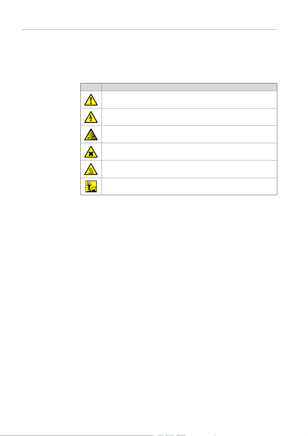
Symbol Significance
Hazard (general)
Hazard by voltage
Hazard by explosive substances/mixtures
Hazard by unhealthy substances
Hazard by high temperature or hot surface
Hazard for the environment/nature/organic life
1.1.2 Warning levels / signal words
DANGER
Risk or hazardous situation which will result in severe personal injury or death.
WARNING
Risk or hazardous situation which could result in severe personal injury or death.
CAUTION
Hazard or unsafe practice which could result in less severe or minor injuries.
NOTICE
Hazard which could result in property damage.
6
8012707/ZVF9/V2-1/2019-04 | SICKOPERATING INSTRUCTIONS | GM32
Subject to change without notice
Page 7
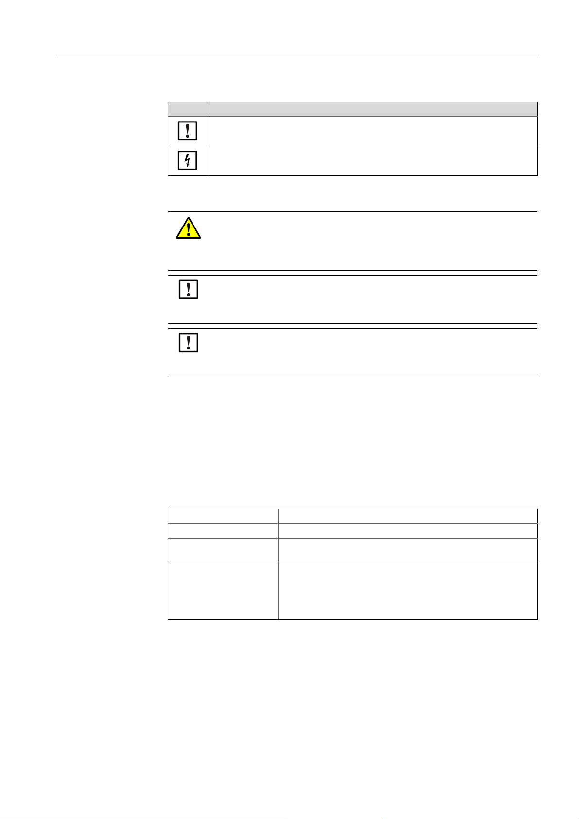
1.1.3 Information symbols
Symbol Significance
Important technical information for this product
Important information on electric or electronic functions
1.2 Main instructions for operation
WARNING: Danger resulting from escaping gas when the SR-unit is swiveled
out
Excess pressure in the gas duct can cause hot and/or noxious gases to escape when
the SR-unit is swiveled out.
▸ Swivel the SR-unit out only when you have taken suitable safety measures.
CAUTION: If the hinge pin has not been correctly inserted, the SR-unit can
drop when swiveled out.
▸ Check the hinge pin is completely pressed down before swiveling the SR-unit out (see
“Install the SR-unit:”, page 36).
ABOUT THIS DOCUMENT 1
CAUTION: Danger of contamination caused by purge air failure (for GM32 with
GMP probe)
▸ If a failure of the purge air supply occurs, take immediate measures to protect the
1.3 Intended use
1.3.1 Purpose of the device
The GM32 serves exclusively for emission and process monitoring of gases in industrial
plants.
GM32 measures continuously directly in the gas duct (in-situ).
1.4 Product identification
Product name GM32
Product variant Version with measuring probe
Manufacturer
Location of type plates
measuring system (see “Error messages”, page 56).
SICK AG · Erwin-Sick-Str. 1
D-79183 Waldkirch · Germany
Sender/receiver unit: On the right side and on the intermediate
enclosure
Connection unit: On the right side and inside
For GMP probe: On the purge air fixture
For GPP probe: On the flange fixture
1.5 Responsibility of user
Designated users
The GM32 may be operated by competent persons only who, based on their device-specific
training and knowledge of the device as well as knowledge of the relevant regulations, can
assess the tasks given and recognize the dangers involved.
8012707/ZVF9/V2-1/2019-04 | SICK OPERATING INSTRUCTIONS | GM32
Subject to change without notice
7
Page 8

1 ABOUT THIS DOCUMENT
Correct use
▸ Use the device only as described in these Operating Instructions.
The manufacturer bears no responsibility for any other use.
▸ Perform the specified maintenance work.
!▸
Do not remove, add or modify any components to or on the device unless described and
specified in the official manufacturer information.
Otherwise:
– Any warranty by the manufacturer becomes void.
– The device could become dangerous.
Special local conditions
▸ Follow all local laws, regulations and company-internal operating directives applicable at
the installation location.
Retention of documents
These Operating Instructions:
▸ Must be available for reference.
▸ Must be passed on to new owners.
1.6 Additional documentation/information
▸ Pay attention to the supplied documents.
Additional instructions
The following documents are applicable in addition to these Operating Instructions:
● Technical Information GM32 (option)
● Operating Instructions for purge air supply SLV4 (for GMP probe)
● Operating Instructions, “Modular I/O System” (option)
● Final inspection record
● CD-ROM with SOPAS ET
8
8012707/ZVF9/V2-1/2019-04 | SICKOPERATING INSTRUCTIONS | GM32
Subject to change without notice
Page 9

2 Product description
2.1 Product description
The GM32 gas analyzer serves for continuous measurement of gas concentrations in
industrial plants.
GM32 is an in-situ measuring system which means measuring is done directly in the gas
carrying duct.
PRODUCT DESCRIPTION 2
● Measuring components: SO
● GM32-TRS-PExx version: TRS components.
● Measuring principle: Differential Optical Absorption Spectroscopy (DOAS).
2.1.1 Device versions
[1] Total reduced sulfurs
[2] Methyl mercaptan
[3] Dimethyl sulphide
[4] Dimethyl disulphide
, NO, NO2 and NH3 (device specific) as well as the reference
2
variables temperature and pressure.
(Only for kraft pulp mills. Only with GPP probe)
Version Components measured Component
All T, p --GM32-1 SO
GM32-2 SO
GM32-3 SO2, NO, NO
2
, NO NO
2
2
GM32-4 NO NO
GM32-5 SO2, NO, NH
GM32-6 NO, NO2, NH
GM32-7 NO, NO
GM32-8 NO, NH
GM32-9 SO2, NO, NO2, NH
3
3
2
3
3
GM32-TRS-PE01 H2S --GM32-TRS-PE02 TRS
GM32-TRS-PE03 H
GM32-TRS-PE04 TRS, SO
GM32-TRS-PE05 H
GM32-TRS-PE06 TRS, SO
GM32-TRS-PE07 TRS, H