

Page 1

GM32 Ex
In-situ Gas Analyzer Cross-Duct Version
Installation, Operation, Maintenance
O P E R A T I N G I N S T R U C T I O N S
Page 2

Described product
GM32 Ex
Cross-Duct version
Manufacturer
SICK AG
Erwin-Sick-Str. 1
79183 Waldkirch
Germany
Production location
SICK AG
Nimburger Str. 11
79276 Reute
Germany
Legal information
This work is protected by copyright. Any rights derived from the copyright shall be
reserved for SICK AG. Reproduction of this document or parts of this document is only
permissible within the limits of the legal determination of Copyright Law. Any modifica‐
tion, shortening or translation of this document is prohibited without the express written
permission of SICK AG.
The trademarks stated in this document are the property of their respective owner.
© SICK AG. All rights reserved.
Original document
This document is an original document of SICK AG.
2
O PE R AT I NG IN S TR U CT I ON S | GM32 Ex 8015594/YV18/V1-8/2017-08 | SICK
Subject to change without notice
Page 3

Contents
CONTENTS
1 About this document........................................................................ 7
1.1 Function of this document....................................................................... 7
1.2 Scope of application................................................................................. 7
1.3 Target groups / qualification requirements............................................ 7
1.4 Further information................................................................................... 7
1.5 Data integrity............................................................................................. 7
1.6 Symbols and document conventions...................................................... 8
1.6.1 Warning symbols...................................................................... 8
1.6.2 Warning levels / Signal words................................................. 8
1.6.3 Information symbols................................................................ 9
2 Safety information............................................................................ 10
2.1 Main operating information..................................................................... 10
2.2 Warnings on the device............................................................................ 12
2.3 Intended use............................................................................................. 12
2.3.1 Purpose of the device.............................................................. 13
2.3.2 Operation in potentially explosive atmosphere...................... 13
2.4 Responsibility of user............................................................................... 14
3 Product description........................................................................... 15
3.1 Product identification............................................................................... 15
3.2 Device version........................................................................................... 15
3.3 Device variants......................................................................................... 16
3.4 Options...................................................................................................... 16
3.5 SOPAS ET (PC program)............................................................................ 16
3.6 Reference cycle......................................................................................... 17
3.7 Check cycle............................................................................................... 17
3.8 Layout and function.................................................................................. 19
3.9 Purge air unit............................................................................................. 20
3.10 Explosion protection in accordance with ATEX....................................... 20
3.10.1 Zone separation GM32 EX ATEX 3G....................................... 20
3.10.2 Pressurized enclosure............................................................. 21
3.10.2.1 ................................................................................. 21
3.11 Connecting hose between SR-unit and junction box.............................. 22
4 Transport and storage....................................................................... 23
4.1 Transport safety device............................................................................ 23
4.2 Storage...................................................................................................... 23
5 Mounting............................................................................................. 24
5.1 Information on installation in potentially explosive atmospheres......... 24
5.2 Preparing the sampling point................................................................... 25
5.3 Scope of delivery....................................................................................... 25
5.3.1 Checking the delivery state..................................................... 26
8015594/YV18/V1-8/2017-08 | SICK O PE R AT I NG IN S TR U CT I ON S | GM32 Ex
Subject to change without notice
3
Page 4

CONTENTS
5.4 Installation sequence............................................................................... 26
5.4.1 Overview of the installation steps (duct-side preparation)... 26
5.4.2 Install flanges with tube.......................................................... 26
5.4.3 Installing the connection unit................................................. 28
5.4.3.1 Fitting the FS850S.................................................. 29
5.4.4 Installing the purge air unit..................................................... 30
5.4.4.1 Start-up of the purge air supply............................. 30
6 Electrical installation........................................................................ 32
6.1 Electrical installation safety information................................................. 32
6.2 Connection overview................................................................................ 34
6.2.1 Lines......................................................................................... 35
6.3 Connecting interfaces ............................................................................. 35
6.3.1 Connecting I/O interfaces (option)......................................... 35
6.3.1.1 Connection diagram for variant 3G....................... 36
6.3.1.2 Default values for interfaces.................................. 38
6.4 Connecting the connection hose to the SR-unit on the junction box.... 39
6.5 Connecting pressure, temperature and purge air monitor ................... 40
6.6 Connecting the potential equalization on the purge air fixture............. 40
6.7 Connecting the Ex overpressure control FS850S................................... 41
6.8 Electrical connection of SR-unit............................................................... 42
6.9 Preparing the power supply...................................................................... 43
6.10 Connecting the potential equalization to the SR-unit............................. 44
7 Commissioning.................................................................................. 45
7.1 Safety information for start-up................................................................. 45
7.2 Material required ..................................................................................... 46
7.3 Check before start-up............................................................................... 46
7.4 Overview of start-up steps....................................................................... 46
7.5 Fitting the purge air fixtures on the flange with tube............................. 47
7.6 Installing the device flange on the purge air fixture............................... 47
7.7 Aligning device flanges and purge air fixtures........................................ 49
7.8 Connecting the protective gas on the SR-unit........................................ 50
7.8.1 Feeding protective gas............................................................ 51
7.8.2 Switching the pressurized enclosure on................................. 51
7.9 Installing the SR-unit and reflector unit on the device flange............... 52
7.10 Optical fine alignment of the SR-unit ..................................................... 52
7.11 Fitting the weatherproof cover (option)................................................... 53
8 Operation............................................................................................ 55
8.1 Safety......................................................................................................... 55
8.2 GM32 operator panel............................................................................... 55
8.2.1 LEDs.......................................................................................... 56
8.2.2 Function buttons...................................................................... 57
8.2.3 Setting the display contrast.................................................... 58
8.2.4 Menu tree................................................................................. 58
4
O PE R AT I NG IN S TR U CT I ON S | GM32 Ex 8015594/YV18/V1-8/2017-08 | SICK
Subject to change without notice
Page 5

CONTENTS
8.2.4.1 Diagnosis................................................................. 59
8.2.4.2 Check cycle - results of last check cycle............... 59
8.2.4.3 Alignment check (option) - automatic optical
alignment check..................................................... 60
8.2.4.4 Alignment adjust - manual optical alignment....... 60
8.2.4.5 Maintenance mode - set Maintenance mode ...... 62
9 Maintenance...................................................................................... 64
9.1 Safety ........................................................................................................ 64
9.2 Maintenance plan .................................................................................... 66
9.2.1 Consumable parts, expendable parts and spare parts........ 66
9.3 Preparation work....................................................................................... 67
9.4 Function test of the pressurized enclosure system................................ 67
9.5 Swiveling out and removing the SR-unit or reflector unit....................... 68
9.6 Visual inspection....................................................................................... 69
9.7 Cleaning the window................................................................................. 70
9.8 Check/replace the desiccant cartridge................................................... 70
9.9 Replacing the activated charcoal bag..................................................... 71
9.10 Replacing the sender lamp...................................................................... 72
10 Troubleshooting................................................................................. 75
10.1 Safety......................................................................................................... 75
10.2 Visual inspection....................................................................................... 76
10.3 Device not functioning.............................................................................. 77
10.4 Overpressure monitoring failure.............................................................. 77
10.5 Measured values clearly incorrect........................................................... 78
10.6 Sample gas penetrating........................................................................... 78
10.7 Corrosion on flange.................................................................................. 78
10.8 Measured value blinks............................................................................. 78
10.9 Error messages......................................................................................... 78
10.9.1 Example of an error message................................................. 78
10.9.2 Error messages........................................................................ 80
10.10 Repairing inadequate purge air supply................................................... 84
10.11 Malfunctions on the connection unit ..................................................... 84
11 Decommissioning............................................................................. 85
11.1 Safety information on shutting down...................................................... 85
11.2 Decommissioning of subassemblies with explosion relevance............. 87
11.3 Removing the device................................................................................ 87
11.4 Environmentally compatible disposal ..................................................... 87
12 Technical data.................................................................................... 89
12.1 System: GM32 Ex..................................................................................... 89
12.2 GM32 Ex sender/receiver unit................................................................ 90
12.3 Reflector unit GM32 Ex............................................................................ 90
12.4 Purge air fixture: Sender/receiver unit GM32 Ex................................... 91
12.5 Purge air fixture: Reflector unit GM32 Ex................................................ 91
8015594/YV18/V1-8/2017-08 | SICK O PE R AT I NG IN S TR U CT I ON S | GM32 Ex
Subject to change without notice
5
Page 6

CONTENTS
12.6 Connection unit, Ex version I/O module................................................. 91
12.7 Dimension drawings: Sender/receiver unit Ex version.......................... 92
12.8 Dimension drawings: Reflector unit........................................................ 93
12.9 Dimension drawings: Ex purge air fixtures (on SR and reflector side).. 94
12.10 Dimension drawings: Connection unit version 3G................................. 95
12.11 Dimension drawings: Mounting flange DN100....................................... 96
12.12 Dimension drawing, weatherproof cover, SR-unit................................... 96
12.13 Technical data for enclosure pressurization system.............................. 96
12.13.1 Technical data protective gas................................................. 96
12.13.2 Technical data enclosure........................................................ 97
12.13.3 Pressurized enclosure system settings.................................. 97
13 Annex.................................................................................................. 98
13.1 Conformities.............................................................................................. 98
13.2 Electrical protection.................................................................................. 98
13.3 Ex certifications........................................................................................ 98
14 Index.................................................................................................... 100
6
O PE R AT I NG IN S TR U CT I ON S | GM32 Ex 8015594/YV18/V1-8/2017-08 | SICK
Subject to change without notice
Page 7
ABOUT THIS DOCUMENT 1
1 About this document
1.1 Function of this document
These Operating Instructions describe:
Device components
•
Installation
•
Operation
•
Maintenance work required for reliable operation
•
1.2 Scope of application
These Operating Instructions are only valid for the in-situ gas analyzer with the designa‐
tion GM32 Ex Cross-Duct.
They are not valid for other in-situ gas analyzers from SICK.
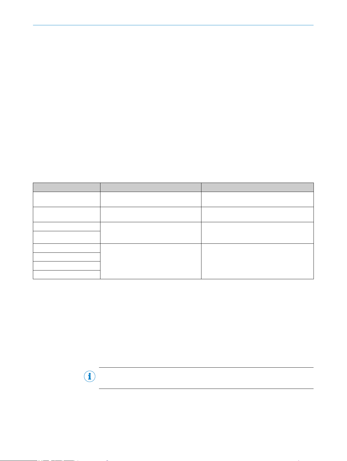
1.3 Target groups / qualification requirements
Table 1: Qualification requirements
Tasks User groups Qualification
Assembly Operator / system integrator e.g. plant operator, unskilled in measurement
technology
Electrical installation Qualified personnel Authorized electrician (authorized skilled electri‐
cian or person with similar training)
Initial start-up
Returning to operation
Decommissioning
Operation
Maintenance
Troubleshooting
Authorized operator Ü
Operator / system integrator
•
Authorized operator Ü
•
General knowledge in measurement technology,
specialist device knowledge (possibly customer
training at SICK)
e.g. plant operator, unskilled in measure‐
•
ment technology
Authorized electrician (authorized skilled
•
electrician or person with similar training)
1.4 Further information
Operating Instructions of the purge air supply
•
Final inspection record
•
CD-ROM with SOPAS ET
•
Optional: Technical information
•
Optional: Operating Instructions Modular System I/O
•
3G / Zone 2
FS850S Pressurized Enclosure Manual
•
Manual, Purge medium valve SVD.L.2.-AI00
•
NOTE
Observe all supplied documents.
b
1.5 Data integrity
SICK AG uses standardized data interfaces such as, for example, standard IP technol‐
ogy, in its products. The focus here is on product availability and features.
8015594/YV18/V1-8/2017-08 | SICK O PE R AT I NG IN S TR U CT I ON S | GM32 Ex
Subject to change without notice
7
Page 8
1 ABOUT THIS DOCUMENT
SICK AG always assumes that the customer is responsible for the integrity and confi‐
dentiality of data and rights involved in connection with using the products.
In all cases, the customer is responsible for the implementation of safety measures
suitable for the respective situation, e.g., network separation, firewalls, virus protection
and patch management.
1.6 Symbols and document conventions
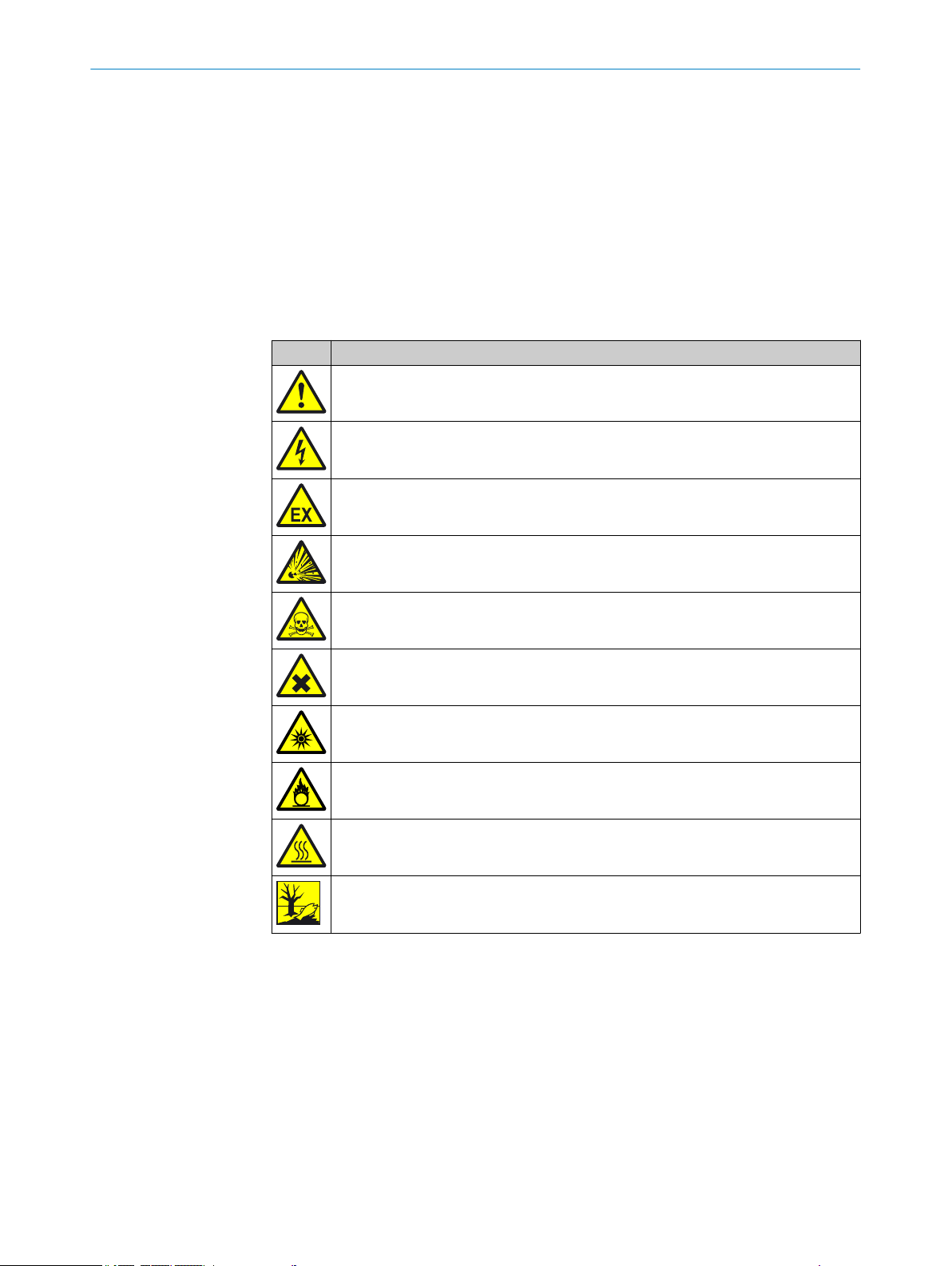
1.6.1 Warning symbols
Table 2: Warning symbols
Symbol Significance
Hazard (general)
Hazard by voltage
Hazard in potentially explosive atmospheres
Hazard by explosive substances/mixtures
Hazard by toxic substances
Hazard by unhealthy substances
Hazard by ultraviolet radiation (UV light)
Hazard by oxidizing substances
Hazard by high temperature
Hazard for the environment/nature/organic life
1.6.2 Warning levels / Signal words
DANGER
Risk or hazardous situation which will result in severe personal injury or death.
WARNING
Risk or hazardous situation which could result in severe personal injury or death.
CAUTION
Hazard or unsafe practice which could result in less severe or minor injuries.
Notice
Hazard which could result in property damage.
8
O PE R AT I NG IN S TR U CT I ON S | GM32 Ex 8015594/YV18/V1-8/2017-08 | SICK
Subject to change without notice
Page 9
Note
Hints
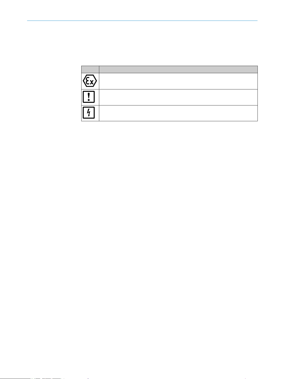
1.6.3 Information symbols
Table 3: Information symbols
Symbol Significance
ABOUT THIS DOCUMENT 1
Information on consistency of the product relative to Guideline 2014/34/EU (ATEX)
Important technical information for this product
Important information on electric or electronic functions
8015594/YV18/V1-8/2017-08 | SICK O PE R AT I NG IN S TR U CT I ON S | GM32 Ex
Subject to change without notice
9
Page 10
2 SAFETY INFORMATION
2 Safety information
2.1 Main operating information
Work on the device
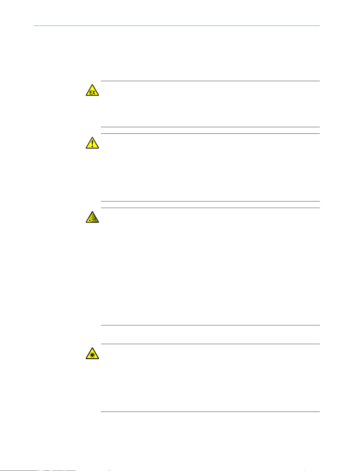
WARNING
Risk of explosion
Work on the device assumes an Ex free zone at the installation location otherwise there
is an explosion risk.
Ensure the work area is Ex free when working on the device.
b
DANGER
Risk for system safety through work on the device not described in these Operating
Instructions
Carrying out work on the device not described in these Operating Instructions or associ‐
ated documents can lead to unsafe operation of the measuring system and therefore
endanger plant safety.
Only carry out the work on the device described in these Operating Instructions
b
and associated documents.
DANGER
Risk of explosion through incorrect performance of maintenance work
Incorrect performance of maintenance work in potentially explosive atmospheres can
cause serious injuries to people and damage during operation.
Maintenance work and start-up activities as well as checks must be performed by
•
experienced/trained technicians having knowledge of the relevant rules and regu‐
lations for potentially explosive atmospheres, especially:
– Ignition protection types
– Installation procedures
– Zone classification
Standards to be applied:
•
– IEC 60079-14, Annex F: Knowledge, skills and competencies of responsible
persons, operatives and designers
– IEC 60079-17: Electrical installations inspection and maintenance
– IEC 60079-19: Equipment repair, overhaul and reclamation
Noxious UV radiation
DANGER
Damage to eyes and skin by UV radiation
The in-situ gas measuring device GM32 emits UV radiation when the SR-unit or reflec‐
tor unit is opened during operation. Exposure of the unprotected skin and eyes to radia‐
tion is dangerous to health.
10
Disconnect the power supply of the device before opening the device.
b
Wear suitable protective goggles and protective gloves when work on the open
b
device with the power supply connected is performed.
O PE R AT I NG IN S TR U CT I ON S | GM32 Ex 8015594/YV18/V1-8/2017-08 | SICK
Subject to change without notice
Page 11
SAFETY INFORMATION 2
Escaping hot gas
DANGER
Risk of fire through hot gas escaping in installations with overpressure conditions
On installations with overpressure, the purge air hose can be severely damaged by
escaping hot gas and can catch fire depending on the temperature. On installations
with overpressure and gas temperatures over 200°C at the same time:
Regularly check the functionality of the reverse flow safeguard in the purge air fix‐
b
tures.
Potential equalization
CAUTION
Device damage through incorrect or non-existing grounding
To avoid device damage, a correctly connected potential equalization is mandatory on
all system components with external ground connections in all operating conditions.
Connect a potential equalization on all planned points on the device components.
b
Ensure the potential equalization is connected during all work on the device
b
described in these Operating Instructions.
Contamination caused by purge air failure
CAUTION
A faulty purge air supply can damage the measuring system
The measuring system can no longer be protected from contaminated sample gas and
is damaged.
When the purge air supply is faulty, immediately perform all actions described in
b
these Operating Instructions.
Responsibility for system safety
ATTENTION
Responsibility for the safety of a system
The person setting the system up is responsible for the safety of the system in which
the device is integrated.
8015594/YV18/V1-8/2017-08 | SICK O PE R AT I NG IN S TR U CT I ON S | GM32 Ex
Subject to change without notice
11
Page 12

1
2
3
4
5
6
7
8
9
1 2 3
2 SAFETY INFORMATION
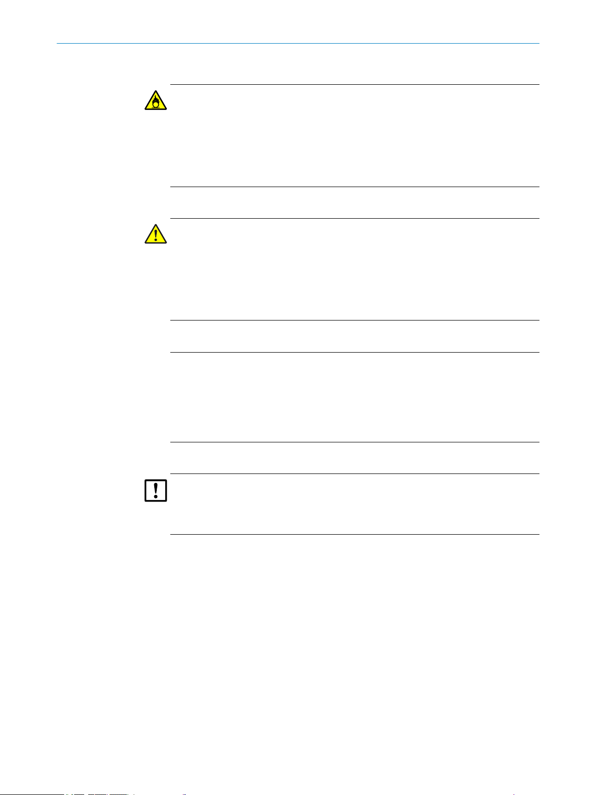
2.2 Warnings on the device
GM32 Ex SR-unit
Figure 1: Sender/receiver unit from the front, the side and with the intermediate housing open
Sender/receiver unit, front side
1 Warning sign protective gas:
°
°
°
2 Warning sign: Pull power plug before opening the device
3 Mandatory sign: Wear eye protection
4 Warning sign: Do not disconnect when live
Sender/receiver unit, right side
5 Type plate GM32 Ex 3G
6 Sampling point designation (optional)
7 Danger sign: UV light
Sender/receiver unit, intermediate housing
8 Type plate GM32 Ex 3G
9 Warning sign: Hot surface
Protective gas outlet
Risk of suffocation when using inert gases
20 minutes waiting time before opening the enclosure
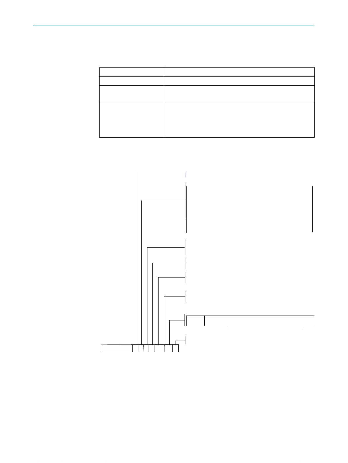
GM32 Ex connection unit
Connection unit for GM32 Ex, front side
1 Warning sign protective gas:
Protective gas outlet
°
Risk of suffocation when using inert
°
gases
20 minutes waiting time before open‐
°
ing the enclosure
2 Warning sign: Pull power plug before open‐
ing the device
3 General warning sign: Warning of a danger
area
Figure 2: GM32 Ex connection unit
2.3
12
Intended use
O PE R AT I NG IN S TR U CT I ON S | GM32 Ex 8015594/YV18/V1-8/2017-08 | SICK
Subject to change without notice
Page 13

2.3.1 Purpose of the device
The device serves exclusively for emission and process monitoring of gases in industrial
plants.
The device measures continuously directly in the gas duct (in-situ).
2.3.2 Operation in potentially explosive atmosphere
3G / Zone 2: Connection unit and sender/receiver unit
The GM32 Ex corresponds to the ATEX category (according to
•
ATEX 2014/34/EC):
X II 3G Ex pzc op is [ia] IIC T3 Gc
GM32 Ex meets the following IECEx qualification:
•
Ex pzc op is [ia] IIC T3 Gc
Special conditions (X identification)
•
A measuring function for explosion protection is not part of
°
the EC type approval
The duct with sample gas contact must be a non-potentially
°
explosive atmosphere when overpressure against the
atmosphere is present in the duct
If the duct has underpressure against the atmosphere, this
°
area may correspond to Zone 2
Observe the Ex identification.
•
The Ex identification is on the type plate. Example:
SICK
GM32-xxx-EX3G (xxx=internal type number)
SN: yyyy yyyyy (serial number)
-20 °C ≤ Ta ≤ 55 °C
X
Explosion protection relating to optical radiation in the measur‐
•
ing channel
The explosion protection relating to optical radiation in the meas‐
uring channel is satisfied in accordance with the temperature
range (-20°... +60 °C) specified by ATX/IECEx. The plant opera‐
tor must evaluate Ex atmospheres possibly present for exhaust
gas temperatures exceeding this range separately and take suit‐
able protective measures!
Location of Ex relevant subassemblies, see Chapter “Design
w
and Function”.
Do not remove, add or modify any components to or on the
w
device unless described and specified in the official manu‐
facturer information. Otherwise the approval for the device
for use in potentially explosive atmospheres becomes void.
Adhere to the maintenance intervals, see Chapter “Mainte‐
w
nance plan”.
After switching off the main power supply: Wait 20 minutes
w
before opening the enclosure.
SAFETY INFORMATION
2
8015594/YV18/V1-8/2017-08 | SICK O PE R AT I NG IN S TR U CT I ON S | GM32 Ex
Subject to change without notice
13
Page 14

2 SAFETY INFORMATION
2.4 Responsibility of user
Designated users
see "Target groups / qualification requirements", page 7.
Correct project planning
Basis of this Manual is the delivery of the device according to the preceding
•
project planning (e.g., based on the SICK application questionnaire) and the rele‐
vant delivery state of the device (see delivered System Documentation).
Contact SICK Customer Service if you are not sure whether the device corre‐
w
sponds to the state defined during project planning or to the delivered system
documentation.
Special local conditions
In addition to the information in these Operating Instructions, follow all local laws, tech‐
nical rules and company-internal operating directives applicable wherever the device is
installed.
Read the Operating Instructions
Read and observe these Operating Instructions.
b
Observe all safety instructions.
b
If anything is not clear: Please contact SICK Customer Service.
b
Retain documents
These Operating Instructions:
Must be available for reference.
b
Must be passed on to new owners.
b
14
O PE R AT I NG IN S TR U CT I ON S | GM32 Ex 8015594/YV18/V1-8/2017-08 | SICK
Subject to change without notice
Page 15
3 Product description
a*
Ausführung/Device
Komponenten/Components
Messlanze/ Measuring probe
Cross-Duct
Ausführung und Kalibierung / calibration
Geräteart 1
Device type 1
Geräteart 2
Device type 2
Dokumentation / Documentation
GM32 -
Ex2G
Ex3G
Ex-Gerät 2G (Zone1)
Ex-Gerät 3G (Zone2)
Ex-device 2G (Zone1)
Ex-device 3G (Zone2)
**** **
*
0
7
6
5
4
3
2
1
9
Sonderausführung
SO2
SO2, NO, NOx
SO2, NO, NO2, NOx
NO, NOx
SO2, NO, NH3, NOx
SO2, NO, NH3, NOx
NO, NO2, NOx
SO2, NO, NO2, NH3, NOx
special model
3.1 Product identification
Product name GM32 Ex
Device version Cross-Duct version
Manufacturer SICK AG
Type plates
3.2 Device version
Type code for Ex device versions
PRODUCT DESCRIPTION 3
Erwin-Sick-Str. 1 D-79183 Waldkirch · Germany
Sender/receiver unit: On the right side and on the intermedi‐
•
ate enclosure
Connection unit: On the right and inside
•
On the purge air fixture: On the tube
•
On the reflector
•
8015594/YV18/V1-8/2017-08 | SICK O PE R AT I NG IN S TR U CT I ON S | GM32 Ex
Subject to change without notice
Figure 3: Type code for GM32 Ex
Ex version designation
*a
15
Page 16
Ausführung Device
Anschlusseinheit - Connection unit housing
Anschlusseinheit - Analoge/Digitale Schnittstellen
Connection unit - I/Os
Anschlusseinheit - Zusatzbestückung
Connection unit - additional assembly
Geräteart Device type
Dokumentation / Documentation
Ex2G
Ex3G
Ex-Gerät 2G (Zone1)
Ex-Gerät 3G (Zone2)
Ex-device 2G (Zone1)
Ex-device 3G (Zone2)
GM32Gasmessgerät
Typ
Measuring system for gas
Type
-A
Anschlusseinheit
Connection unit
a*
GM32 - A
***
*
3 PRODUCT DESCRIPTION
Type code for Ex connection unit
Figure 4: Type code for GM32 Ex connection unit
a*
Ex connection unit designation
3.3 Device variants
“Basic” variant
Reference cycle, see "Reference cycle", page 17: Correction of internal drifts.
•
Zero point check
Automatic mirror tracking: Automatic adjustment of optical axis
•
Logbook: System messages are recorded in a logbook
•
Network: Ethernet interface with OPC standard
•
Ethernet: 1 x fiber optics connection on connection unit
•
“Pro” variant
As “Basic” variant. In addition:
TÜV-tested for equipment subject to authorization
•
Check cycle, see "Check cycle", page 17: Reference cycle (as in the “Basic” var‐
•
iant) followed by a cycle to check and output the zero and check point. The check
cycle creates the QAL3 values (quality assurance of automated measuring sys‐
tems). The QAL3 values can be displayed with SOPAS ET.
Operator panel: Measured values, operational state and malfunction messages
•
are displayed in clear text on a monitor
QAL3 Tool (CUSUM chart)
•
3.4 Options
3.5 SOPAS ET (PC program)
16
O PE R AT I NG IN S TR U CT I ON S | GM32 Ex 8015594/YV18/V1-8/2017-08 | SICK
I/O modules (Analog Out, Digital Out, Digital In, Analog In)
•
SCU: Operating unit to control several analyzers with SCU capability (see SCU Oper‐
•
ating Instructions)
Super calibration: Several applications/calibrations, e.g., for spare devices
•
Measuring range switch-over (analog outputs). The valid measuring range is sig‐
•
naled via a digital output (configured).
Weatherproof cover
•
SOPAS ET enables:
Subject to change without notice
Page 17

•
•
SOPAS ET runs on an external PC connected via the Ethernet interface, see "Connection
overview", page 34, to the GM32.
NOTE
Further information on SOPAS ET:
•
•
3.6 Reference cycle
Internal drifts correction in an adjustable interval (standard: 1 hour, setting: SOPAS ET)
or per command (with SOPAS ET).
Measured value output during the reference cycle: Last valid measured value.
3.7 Check cycle
Check cycle = reference cycle + following check and output of the zero and check points
(70% of full scale value).
PRODUCT DESCRIPTION 3
Additional configuration
Access to logbook GM32
Technical Information GM32
SOPAS ET Help menu
Start a check cycle via
Set interval (SOPAS ET)
•
Command via SOPAS ET
•
External signal (optional)
•
Purpose of check cycle
Check of the zero point and a reference point for each component without feeding
•
test gases
Meets the requirements of EN14181
•
Replaces drift monitoring with test gases according to QAL3
•
Zero point
An internal zero point reflector is swiveled in time-controlled in adjustable intervals. The
emitted light is reflected back in the sender/receiver unit to the detector, the zero spec‐
trum is evaluated with the calibration function and thus the zero points of all ducts
measured and output.
Signaling of maintenance request: Deviation from zero > ± 2% of the FS.
Check cycle
An internal swivel element with two reference filters and an NO-filled cell is swiveled in
during the check cycle in addition to the zero point reflector and the reference value
and concentration value measured. These control values are scaled to 70% of the
selected measuring range.
Signaling of maintenance request: Deviation from setpoint value > ± 2% of the FS.
8015594/YV18/V1-8/2017-08 | SICK O PE R AT I NG IN S TR U CT I ON S | GM32 Ex
Subject to change without notice
17
Page 18
1
2
3
4
7
8
5
6
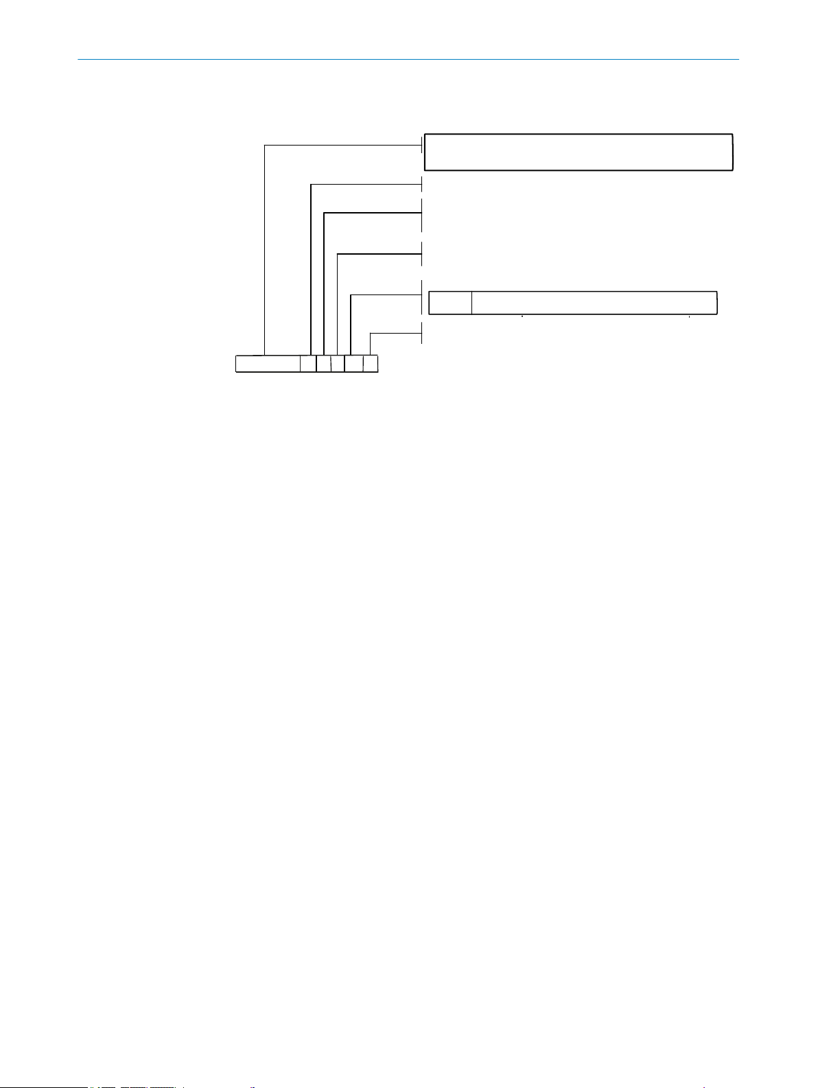
3 PRODUCT DESCRIPTION
Measuring
1
Zero point
2
Check
3
Data recorder
4
Swivel element
5
Zero point reflector
6
Zero point
7
Figure 5: Measuring principle of check cycle
Check point (70% fsc)
8
Output of measured values during the check cycle Last valid measured value
Signal output during the check cycle (optional digital output or
Not_measuring
OPC interface)
Output of determined zero and reference values on analog
outputs
Directly after the check cycle
•
On request via a digital input (option)
•
Signal output during the output Output_control values (optional digital output or OPC inter‐
face)
Output sequence:
1 Zero values for 90 s
2 Reference values for 90 s
Display of zero and reference values, the last check cycle as
well as QAL3 values in SOPAS ET
Display when check of NO cell failed
Menu: Diagnosis/check values
All interfaces: Results of NO cell
•
All interfaces: “0” is output instead of zero and refer‐
•
ence values
Analog output: Live Zero
•
Results of zero and reference measurement are irrele‐
•
vant
18
O PE R AT I NG IN S TR U CT I ON S | GM32 Ex 8015594/YV18/V1-8/2017-08 | SICK
Subject to change without notice
Page 19
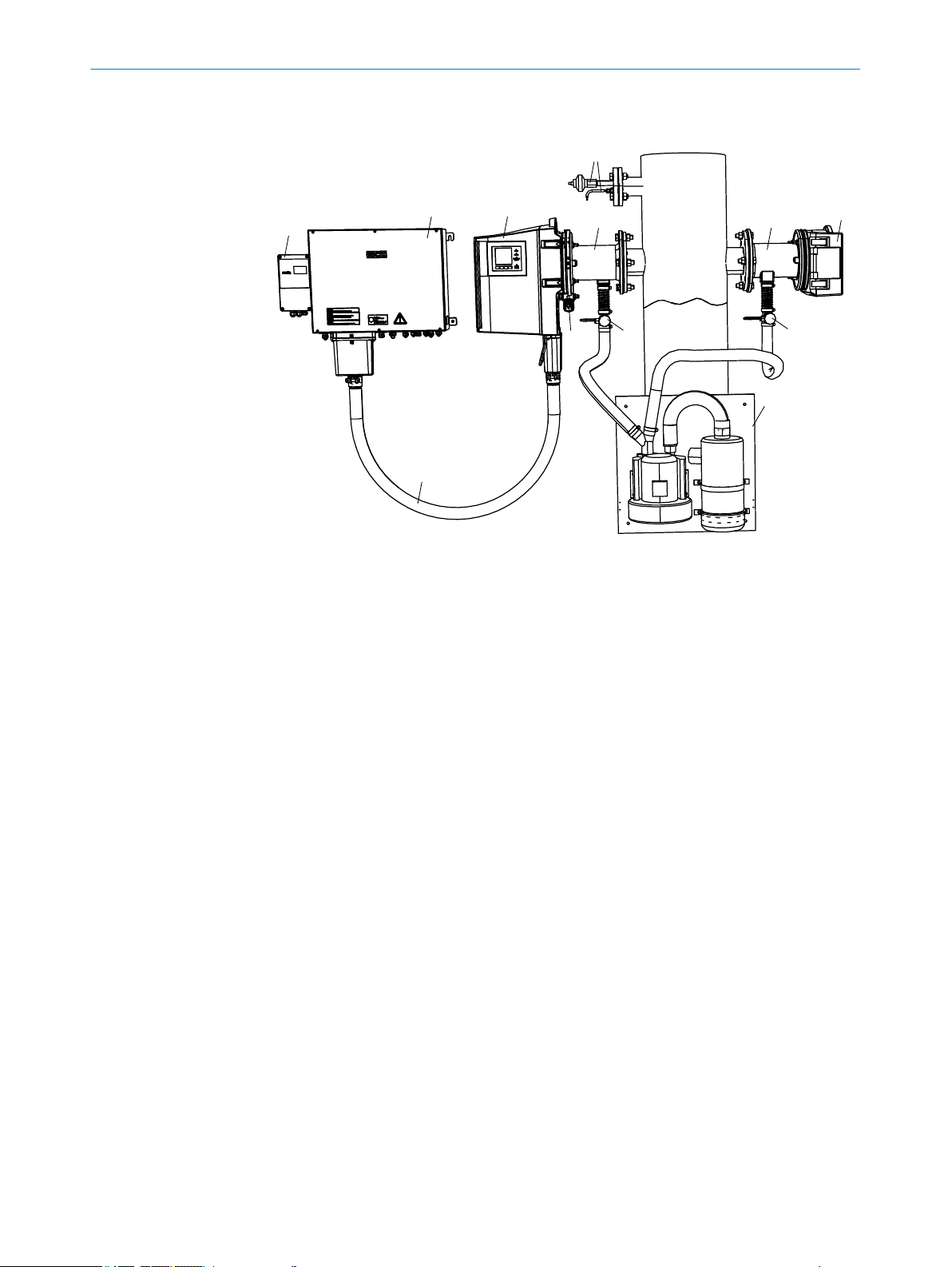
3.8 Layout and function
1
ß
9
8
6
6
5
4
3
2
7
ß
PRODUCT DESCRIPTION 3
Figure 6: Components of the GM32 Ex 3G version
Sender/receiver unit GM32-xxxxxxEX3G (SR-unit)
1
Connection unit GM32- A2xxEX3G
2
Control unit FS850S EEx p
3
Metallic connecting hose between sender/receiver unit and connection unit
4
Purge valve SVP3 G 3/8“-300L EEx p
5
Purge air fixture (without electronics)
6
Reflector unit (without electronics)
7
Temperature and pressure measurement
8
Purge air supply
9
Pressure switch for purge air monitor
ß
Function
The device serves for continuous measurement of gas concentrations in industrial
•
plants
The device is an in-situ measuring system which means measuring is done directly
•
in the gas carrying duct
erence variables temperature and pressure
Measuring principle: Differential Optical Absorption Spectroscopy (DOAS)
•
To maintain measuring reliability, a permanent air flow (optics purge air) protects
•
Measuring components: SO2, NO, NO2 and NH3 (device specific) as well as the ref‐
•
and keeps the optics free from soot and dust particles as well as condensate and
moisture condensation
Ignition protection type “pressurized enclosure” is applicable when using the
•
GM32 Ex in potentially explosive atmospheres. All relevant enclosures of the
sender/receiver unit and connection unit connected together via a pressure-proof
metal hose are purged with a protective gas. The protective gas can be air suc‐
tioned in from the non-potentially explosive atmosphere or an inert gas.
8015594/YV18/V1-8/2017-08 | SICK O PE R AT I NG IN S TR U CT I ON S | GM32 Ex
Subject to change without notice
19
Page 20

DIV 1
DIV 2
Non Ex
1G
2G
Non Ex
3G
Zone 0
Non Ex
Zone 2Zone 1
DI/DOAI
/AO
230 /115 V
GM32 Ex ATEX 3G
Ex p
[op is]
p/t
Ex ia
Ex m
Ex p/ Ex i
Ex eb
mb [ib]
1
Non Ex
ß
à
9
á
7
6
8
5
3
4
ã ä å
2
9
à
ââ
æ
ç
3 PRODUCT DESCRIPTION
3.9 Purge air unit
The purge air unit supplies filtered ambient air to the purge air fixtures.
•
Protects the window of the SR-unit and the reflector against contamination and
•
high gas temperatures
One purge air unit each for SR-unit and reflector unit
•
The purge air is blown into the gas duct through the “flange with tube”.
•
NOTE
Further information on the purge air unit, see Operating Instructions of the purge air
unit.
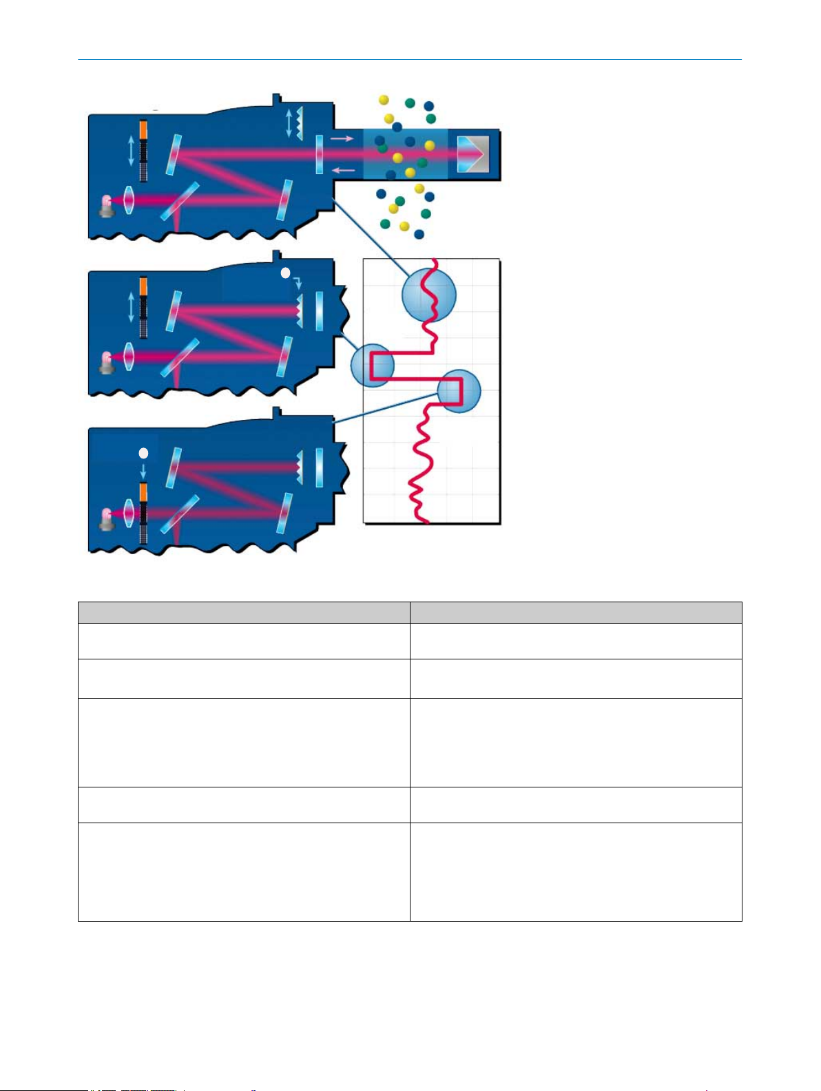
3.10 Explosion protection in accordance with ATEX
3.10.1 Zone separation GM32 EX ATEX 3G
Figure 7: Zone separation GM32 Ex 3G
Components
Control station / measuring station
1
Sender/receiver unit
2
Reflector unit
3
Light source
4
Ex p valve
5
Evaluation unit
6
Overpressure control
7
p/T sensor
8
p sensor
9
20
O PE R AT I NG IN S TR U CT I ON S | GM32 Ex 8015594/YV18/V1-8/2017-08 | SICK
Subject to change without notice
Page 21

Optics purge air according to plant operator's selection
ß
Lines
Purge air hose, optics
à
Connecting hose Ex p
á
Pressure controller, optics purge air Ex i nA
â
Ex p error case signal
ã
Service interface
ä
Feed, Ex p protective gas, provided by operator
å
Feed, optics purge air
æ
Measuring channel
Measuring channel Ex-free; Zone 2 possible with partial vacuum
ç
3.10.2 Pressurized enclosure
Ignition protection type, pressurized enclosure for Zone 2
Purging
All relevant enclosures of the sender/receiver unit and connection unit connected
together via a pressure-proof metal hose are purged with a protective gas. This purging
before the start of the device ensures any possibly present ignitable mixture is safely
removed.
PRODUCT DESCRIPTION 3
Controlling the overpressure in the enclosure
The control FS850P ensures the complete enclosure is held at an overpressure of at
least 0.8 mbar against the atmosphere after the purging which in turn ensures no ignit‐
able gas mixture can penetrate the enclosure.
Protective gas types
Instrument air suctioned in from the area outside the potentially explosive atmos‐
•
phere
Inert gas
•
More information, see "Technical data protective gas", page 96 and Pressurized
Enclosure Operating Instructions.
Alarm signal of the pressurized enclosure when a malfunction occurs
Ex control unit FS850S for category 3G:
Ex control unit FS850S will trigger an alarm signal when the pressurized enclosure
is not in the correct operating state (malfunction).
WARNING
Risk of explosion through incorrect parameter settings
Unauthorized changing of parameters can cause an explosion with fatal consequences.
Never change parameters without authorization.
b
NOTICE
The operating company is responsible for the evaluation of the alarm signal. See the
Pressurized Enclosure System Manual.
8015594/YV18/V1-8/2017-08 | SICK O PE R AT I NG IN S TR U CT I ON S | GM32 Ex
Subject to change without notice
21
Page 22

3 PRODUCT DESCRIPTION
3.11 Connecting hose between SR-unit and junction box
The connection hose between the sender/receiver unit and the junction box
is part of the pressurized enclosure
•
contains electrical connection lines
•
is under overpressure
•
22
O PE R AT I NG IN S TR U CT I ON S | GM32 Ex 8015594/YV18/V1-8/2017-08 | SICK
Subject to change without notice
Page 23
4 Transport and storage
1
2
4.1 Transport safety device
Removing the transport safety device of the SR-unit and the reflector unit
1 Open the lock and swivel the flange fixture up
2 Check the transport safety device for damage
3 Remove the transport safety devices (see Figure)
4 Store the transport safety device
TRANSPORT AND STORAGE 4
4.2 Storage
Figure 8: Remove the transport safety device
Open the lock and swivel the flange fixture up
1
Remove the transport safety device
2
Clean all components of the measuring system with slightly damp cleaning cloths.
b
Use a mild cleaning agent here.
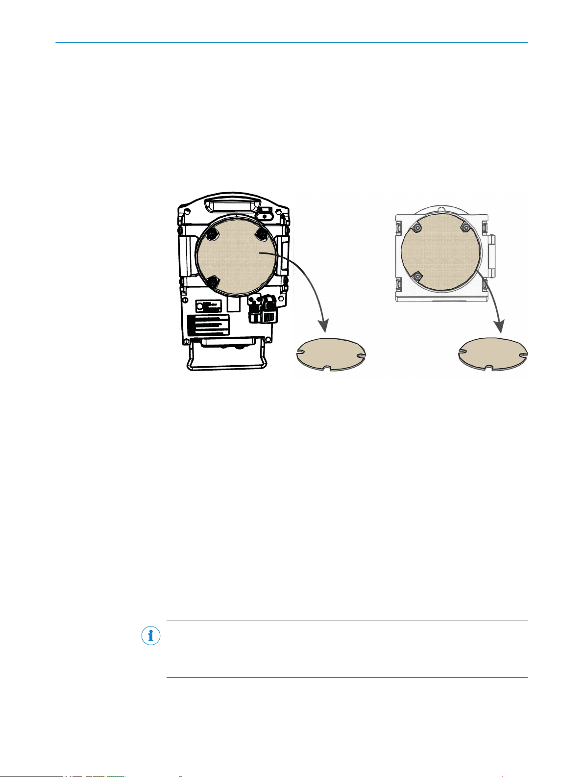
Check the desiccant cartridges and replace, if necessary.
b
After replacing the desiccant cartridges:
Perform a leak tightness check.
b
Protect the openings of the SR-unit and reflector unit from atmospheric influences,
b
preferably with the original transport safety devices.
Pack all components for storage or transport. Preferably use the original packing.
b
Store all components of the measuring system in a dry, clean room.
b
NOTE
The check of the desiccant cartridges and of the leak tightness of the device is descri‐
bed in the Maintenance Chapter, see "Check/replace the desiccant cartridge",
page 70.
8015594/YV18/V1-8/2017-08 | SICK O PE R AT I NG IN S TR U CT I ON S | GM32 Ex
Subject to change without notice
23
Page 24
5 MOUNTING
5 Mounting
5.1 Information on installation in potentially explosive atmospheres
Project planning for measuring channel
NOTICE
Observe information in Chapter "Main operating information".
NOTICE
Hazard when exceeding the temperature classes for hot gas ducts
The temperature class T4 (max. 135 °C), for which the explosion protection of this
device is designed, can be exceeded on hot gas ducts.
Plan appropriate insulation of the duct and the flange during project planning/
b
assembly.
When necessary, ensure adequate ventilation or cooling.
b
Correct installation
DANGER
Risk for system safety through work on the device not described in these Operating
Instructions
Carrying out work on the device not described in these Operating Instructions or associ‐
ated documents can lead to unsafe operation of the measuring system and therefore
endanger plant safety.
Only carry out the work on the device described in these Operating Instructions
b
and associated documents.
DANGER
Risk of explosion through incorrect installation
Incorrect assessment of the installation location as well as all further installation work
in potentially explosive atmospheres can cause serious injuries to people and damage
during operation.
Installation, commissioning, maintenance and inspection may only be carried out
•
by skilled persons having knowledge of the relevant rules and regulations for
potentially explosive atmospheres, especially:
– Ignition protection types
– Installation regulations
– Zone classification
Standards to be applied:
•
– IEC 60079-14, Annex F: Knowledge, skills and competencies of responsible
persons, operatives and designers
– IEC 60079-17: Electrical installations inspection and maintenance
– IEC 60079-19: Equipment repair, overhaul and reclamation
24
Local work safety regulations
•
O PE R AT I NG IN S TR U CT I ON S | GM32 Ex 8015594/YV18/V1-8/2017-08 | SICK
Subject to change without notice
Page 25
WARNING
Risk of injury when the device drops down
The weight of the device can cause it to drop down and cause injuries during the work
described in this Chapter.
Carry out assembly work on parts of the device together with another person when
b
necessary.
Purge air
DANGER
Risk of explosion through suctioning optics purge air from an Ex zone
Zone separation is no longer ensured when the purge air supply to purge the optics is
suctioned in within the Ex zone. This can lead to an explosion.
Always make sure the air for the purge air supply is suctioned in from an Ex free
b
zone.
5.2 Preparing the sampling point
MOUNTING 5
The operator is responsible for preparing the sampling point
NOTICE
Basis for determining the sampling point:
Preceding project planning (e.g., based on the SICK application questionnaire)
•
Regulations of the local authorities
•
Responsibility of the operator
Determine sampling point
•
Preparing the sampling point
•
Feed and drain for protective gas
•
DANGER
Risk of explosion through suctioning optics purge air from an Ex zone
Zone separation is no longer ensured when the purge air supply to purge the optics is
suctioned in within the Ex zone. This can lead to an explosion.
Always make sure the air for the purge air supply is suctioned in from an Ex free
b
zone.
NOTICE
Observe zone separation, see "Zone separation GM700 EX ATEX 3G".
5.3 Scope of delivery
NOTICE
Check the scope of delivery according to the order confirmation/delivery note.
b
8015594/YV18/V1-8/2017-08 | SICK O PE R AT I NG IN S TR U CT I ON S | GM32 Ex
Subject to change without notice
25
Page 26
5 MOUNTING
5.3.1 Checking the delivery state
NOTICE
Check all components have no exterior damage.
b
Ensure the supply voltages on the type plates match the plant conditions.
b
5.4 Installation sequence
5.4.1 Overview of the installation steps (duct-side preparation)
Step Procedure Reference
1 Installing the flange with tube. see "Install flanges with tube",
2 Installing the connection unit. see "Installing the connection unit",
3 Fitting the purge air unit or units. see "Installing the purge air unit",
4 Observing protective gas discharge line (con‐
nection unit).
5 Connecting pressure, temperature and purge
air monitor.
6 Connecting protective gas feed to SR-unit. see "Connecting the protective gas on
page 26.
page 28.
page 30.
see "Fitting the FS850S", page 29.
see "Connecting pressure, temperature
and purge air monitor ", page 40.
the SR-unit", page 50.
5.4.2 Install flanges with tube
DANGER
Hazard through hot, explosive or toxic flue gases
Hot and/or noxious gases can escape during assembly work on the gas duct depending
on the plant conditions.
Work on the gas duct may only be performed by skilled persons who, based on
b
their technical training and knowledge as well as knowledge of the relevant regula‐
tions, can assess the tasks given and recognize the hazards involved.
DANGER
Hazard through hot, toxic and corrosive flue gases
Hot and/or noxious gases can escape during assembly work on the gas duct depending
on the plant conditions.
Switch the plant off when working on the gas duct
b
or
the operator determines the safety measures to be observed during work on the
b
plant when switched on.
CAUTION
Device damage through incorrect/missing insulation of the duct when the measuring
channel is hot
26
When the measuring channel is hot, plan the duct and flange insulation so that
b
the device is protected against high temperatures.
O PE R AT I NG IN S TR U CT I ON S | GM32 Ex 8015594/YV18/V1-8/2017-08 | SICK
Subject to change without notice
Page 27
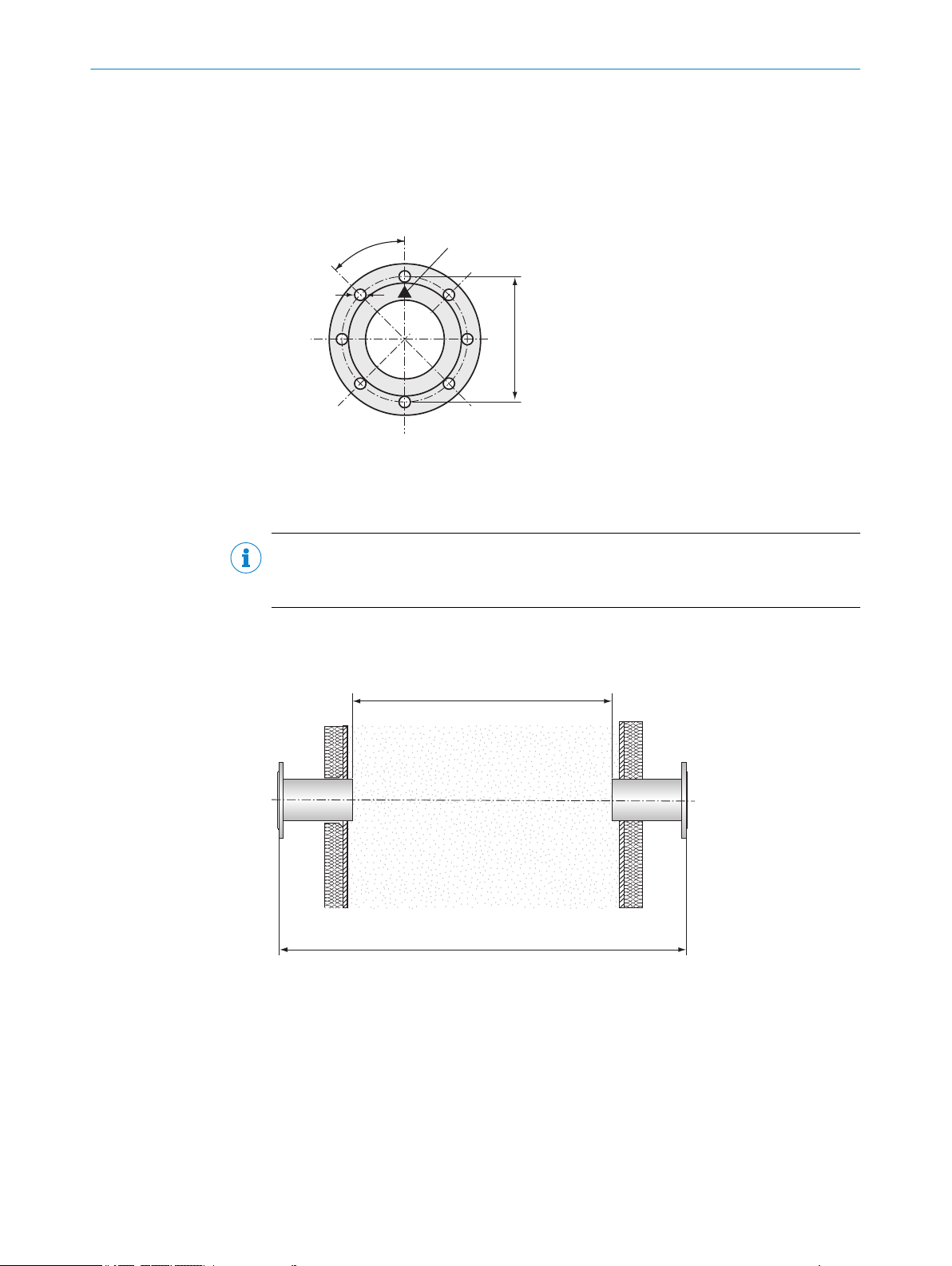
Installing the flange with tube on the gas duct
1
200
18
4
5
°
1
2
1 Cut openings on the gas duct for the flange with tube.
2 Insert the flange with tube. Pay attention to the following:
°
The "Top" marking must point upwards vertically, irrespective of the gas duct
angle.
°
The tube must project at least 30 mm into the gas duct.
Figure 9: "Top" marking on flange with tube
"Top" marking
1
3 Attach the flange with tube.
MOUNTING 5
NOTE
Make sure other devices or installations do not intersect or interrupt the beam path of
the measuring device.
4 Cut the flange opening for the reflector unit accordingly. Caution: Deviation of tube
axis between SR-unit and reflector unit: Max. 1°.
Figure 10: Define the measuring path
Active measuring path
1
Active measuring path "flange - flange"
2
4 Align the flange visually
Remove the protective cap from the adjustment tube.
w
Install the adjustment device (light source on SR-unit side, adjustment tube
w
on reflector side) onto the flanges.
8015594/YV18/V1-8/2017-08 | SICK O PE R AT I NG IN S TR U CT I ON S | GM32 Ex
Subject to change without notice
27
Page 28

2
1
5 MOUNTING
Light source
1
Adjustment tube
2
NOTE
The alignment is performed on the flange where the adjustment tube is located.
– Look in the window of the adjustment tube and focus the light spot of the light
source by shifting the optical beam tube.
– Alignment: The light spot must be shown centrally in the target of the adjustment
tube.
Not aligned correctly
1
Aligned correctly
2
5 Attach the flanges with tube on the gas duct.
NOTICE
In doing so, the alignment of the flanges may not be changed!
6 Perform the check:
– Active measuring path dimension
– Flange - flange dimension
– Alignment
7 Remove the adjustment device again.
8 If necessary, attach duct insulation to protect the measuring device from heat.
5.4.3 Installing the connection unit
The lengths of the lines to the sender/receiver unit match the project planning.
Install the connection unit using the 4 threaded bolts according to project plan‐
b
ning.
NOTE
Dimension drawings of the connection unit and specifications on screw fittings for the
lines, see "Dimension drawings: Connection unit version 3G", page 95.
28
O PE R AT I NG IN S TR U CT I ON S | GM32 Ex 8015594/YV18/V1-8/2017-08 | SICK
Subject to change without notice
Page 29

5.4.3.1 Fitting the FS850S
1
2
Information on fitting
When setting up outdoors, it is recommended to protect the explosion-proof device
against direct atmospheric influences, e.g, with a protective roof.
The fitting position is independent of the location but it should be ensured that the pro‐
tective gas inlet and outlet are in a horizontal axis
MOUNTING 5
Figure 11: Protective gas outlet
Protective gas outlet: Thread G 1"
1
Reference opening (M5 inner thread)
2
Protective gas quality
Instrument air or inert gas
•
Compressed air, class 533 according to ISO 8573-1
•
Solid matter 40 µm (class 1)
•
Pressure dew point ≤ 20 °C (class 3)
•
Oil quality ≤ 0.01 mg/m3 (class 1)
•
The air quality may possibly have to be better depending on the requirements of the
devices fitted in the pressurized enclosure.
Protective gas outlet
It is important that protective gas can flow out of the protective gas outlet against the
atmospheric pressure.
Ensure the unhindered flow of the protective gas.
b
Reference opening
The reference opening must be located in the Ex area.
Make sure the opening is always clear.
b
Line lengths for protective gas supply
Large pressure losses occur during the purge phase (high purge medium throughput)
depending on the supply line diameter. Consider this when dimensioning the supply
line:
Reference values: With 4 mm line diameter (inner diameter), a pressure loss of 500
mbar per meter must be calculated during purging with 2 l/s.
Pressure losses are apparent due to the purge medium throughput being too low and
lead to a longer or never-ending purge phase.
8015594/YV18/V1-8/2017-08 | SICK O PE R AT I NG IN S TR U CT I ON S | GM32 Ex
Subject to change without notice
29
Page 30
5 MOUNTING
NOTE
More information on protective gas,
see "Connecting the Ex overpressure control FS850S", page 41.
•
see "Technical data protective gas", page 96.
•
5.4.4 Installing the purge air unit
NOTE
Purge air hose to the device according to project planning.
NOTE
For information on installing the purge air unit, see the Operating Instructions of the
purge air unit.
5.4.4.1 Start-up of the purge air supply
CAUTION
Risk of device damage caused by inadequate purge air pressure
The purge air supply protects the measuring system from contamination and overheat‐
ing. If the purge air pressure is inadequate, the purge air can not enter the gas duct.
This can result in inadequate provision with purge air and therefore a device failure.
Ensure the purge air pressure is adequate to force the purge air into the gas duct.
b
If you have questions concerning the purge air pressure, contact SICK Customer
b
Service or your local SICK representative.
CAUTION
Risk of device damage through accidentally switching off the power supply
The purge air supply may not be switched off while the measuring system is on the gas
duct.
Attach clearly visible warnings against accidental switching-off to all switching devi‐
b
ces where the purge air supply can be switched off.
30
O PE R AT I NG IN S TR U CT I ON S | GM32 Ex 8015594/YV18/V1-8/2017-08 | SICK
Subject to change without notice
Page 31

2
6
5
7
4
3
1
MOUNTING 5
Purge air fixture
1
Hose adapter
2
Spiral hose
3
Pressure monitor
4
Purge air connection
5
Purge air hose
6
Hose clamps
7
Figure 12: Installing the GM32 purge air unit
Preparing the purge air unit:
1 Switch the power supply of the purge air unit on at the disconnecting device (fitted
by the operator) for the purge air unit
2 Check the function of the purge air unit: A strong air flow must be noticeable.
NOTE
Clarify the cause when no strong air flow is noticeable. Refer to Purge Air Unit
Operating Instructions.
3 Blow out any dust that may have entered the purge air hose.
4 Switch the power supply off again.
Connecting the purge air supply:
1 Pull the spiral hose over the hose adapter (top) and pressure monitor connection
(bottom) and secure each with a hose clamp.
2 Pull the purge air hose over the purge air connection of the differential pressure
sensor and secure with a hose clamp.
3 Switch the power supply of the purge air unit on again.
8015594/YV18/V1-8/2017-08 | SICK O PE R AT I NG IN S TR U CT I ON S | GM32 Ex
Subject to change without notice
31
Page 32

6 ELECTRICAL INSTALLATION
6 Electrical installation
6.1 Electrical installation safety information
Electrical safety
WARNING
Endangerment of electrical safety during installation and maintenance work when the
power supply is not switched off
Before starting the work on the device, ensure the power supply can be switched
b
off using a power disconnector switch/circuit breaker in accordance with DIN EN
61010-1.
Make sure the power disconnector switch is easily accessible.
b
An additional disconnecting device is mandatory when the power disconnector
b
switch cannot be accessed or only with difficulty after installation of the device
connection.
After completion of the work or for test purposes, the power supply may only be
b
activated again by authorized personnel complying with the safety regulations.
WARNING
Endangerment of electrical safety through power cable with incorrect rating
Electrical accidents can occur when the specifications for replacement of a power line
have not been adequately observed.
Always observe the exact specifications in the Operating Instructions (Technical
b
Data Section) when replacing a power line.
DANGER
Danger of electrical accidents
Incorrect performance of electrical work could result in serious electrical accidents.
Only let the work described in the following be carried out by electricians familiar
b
with potential hazards.
CAUTION
Hazard of device damage
Electronic components are accessible when the enclosure is open. The circuit board
can be severely damaged when a contact is not grounded when the power supply is
switched on.
First switch the power supply on when the sender/receiver unit and the control
b
unit are closed.
CAUTION
Device damage through short circuit on the device
The internal electronics can be damaged when signal connections are established and
the power supply is switched on. This is also valid for plug connections.
32
Disconnect the GM32 Ex and any connected devices from the voltage supply.
b
O PE R AT I NG IN S TR U CT I ON S | GM32 Ex 8015594/YV18/V1-8/2017-08 | SICK
Subject to change without notice
Page 33

ELECTRICAL INSTALLATION 6
Ex information
DANGER
Risk of explosion through incorrect performance of maintenance work
Incorrect performance of maintenance work in potentially explosive atmospheres can
cause serious injuries to people and damage during operation.
Maintenance work and start-up activities as well as checks must be performed by
•
experienced/trained technicians having knowledge of the relevant rules and regu‐
lations for potentially explosive atmospheres, especially:
– Ignition protection types
– Installation procedures
– Zone classification
Standards to be applied:
•
– IEC 60079-14, Annex F: Knowledge, skills and competencies of responsible
persons, operatives and designers
– IEC 60079-17: Electrical installations inspection and maintenance
– IEC 60079-19: Equipment repair, overhaul and reclamation
WARNING
Risk of explosion
Some of the work described in this Chapter assumes an Ex free zone.
Wait 20 minutes after switching off the main power supply before opening the
b
enclosure.
WARNING
The Ex certification becomes void when line inlets and plugs without approval are
used
The line inlets and plugs are part of the Ex protection and therefore require approval.
Do not replace line inlets or plugs with other types.
b
Line inlet dimensions, see "Dimension drawings: Connection unit version 3G",
b
page 95.
DANGER
The Ex certification becomes void when line inlets and plugs without approval are
used
The line inlets and plugs are part of the Ex protection and therefore require approval.
Do not replace line inlets or plugs with other types.
b
Line inlet dimensions, see "Dimension drawings, evaluation unit with enclosure
b
pressurization system FS840".
DANGER
Risk of explosion through non-Ex conform installation of the lines to the device
Incorrect installation of the supply lines (power supply, signal and communication lines)
through Ex zones can lead to an electrostatic charge. This creates an increased risk of
explosion.
Install all lines in accordance with EN61010-1 and EN60079-14.
b
Protect lines against electrostatic charges.
b
8015594/YV18/V1-8/2017-08 | SICK O PE R AT I NG IN S TR U CT I ON S | GM32 Ex
Subject to change without notice
33
Page 34

1
9
8
6
7
4
3
2
ß
1
5
8
6 ELECTRICAL INSTALLATION
DANGER
Risk of explosion through incorrect connection of the external sensors
The explosion protection is endangered when the external sensors p/T (in the stack) as
well as the optics purge air monitor (on the purge air fixture) are not connected to the
intrinsically safe terminals provided in the connection unit.
Always connect the external sensors p/T (in the stack) as well as the optics purge
b
air monitor (on the purge air fixture) to the intrinsically safe terminals specified in
the connection unit for this purpose.
Observe the intrinsically safe connection values for the Ex barriers fitted in the
b
evaluation unit in the Operating Instructions delivered.
DANGER
Risk of explosion through unsuitable screw fittings and lines
Only use lines (according to EN60079-14) with suitable outer diameters.
b
Close off cable inlets “vapor-proof” (virtually gas-tight).
b
Protect lines against electrostatic charges.
b
Only open those cable inlets to be used for installing cables. Keep the plugs. Refit
b
the original plug when a cable inlet must be closed again afterwards.
6.2 Connection overview
Figure 13: Overview of electrical connections GM32 Ex 3G / Zone 2
Power supply 115 V / 230 V
1
Warning signal Ex-p control
2
Fiber optics (Ethernet)
3
I/O signal lines
4
34
O PE R AT I NG IN S TR U CT I ON S | GM32 Ex 8015594/YV18/V1-8/2017-08 | SICK
Protective gas supply
5
Connection line, pressure sensor
6
Connection line, temperature sensor
7
Connection line, purge air monitor, pressure switch
8
Connection line, purge valve SVP3 G3G 8"-300L EEx p
9
Subject to change without notice
Page 35

6.2.1 Lines
1
2
3
4
ELECTRICAL INSTALLATION 6
Metallic connecting hose between sender/receiver unit and connection unit
ß
Figure 14: Connection unit version 3G (all specifications in mm)
No. Line opening size Line diameter (clamping
range)
1
2
3
4
Lines Remark
Connection unit — sender/receiver unit with
connecting hose
Differential pressure sensor — connection unit On-site, intrinsically safe I/O connection
Pressure/temperature input On-site, intrinsically safe I/O connection
Ethernet PC/network (fiber optics) On-site, fiber optics
Inputs/outputs On-site: Terminal connection
Connection unit — SCU-P100 (CAN cable) On-site
Table 4: Technical data, M screw fittings
Outer thread M20 x 1.5 M16 x 1.5
Thread length 6 mm
H 23 mm
Cable diameter 10 ... 14 mm 6 ... 10 mm
Key width 24 mm 20 mm
Continuous service temperature -20 ... 95 °C
Material Nickel-plated brass
M16 x 1.5 5 - 11 mm 8
M20 x 1.5 10 - 14 mm 2
M16 x 1.5 5 - 11 mm 3
M16 x 1.5 4 - 8 mm 2
In accordance with project planning:
5 m
•
10 m
•
Number
6.3 Connecting interfaces
6.3.1 Connecting I/O interfaces (option)
CAUTION
Never lay power supply cables directly next to signal cables.
8015594/YV18/V1-8/2017-08 | SICK O PE R AT I NG IN S TR U CT I ON S | GM32 Ex
Subject to change without notice
35
Page 36

1
â
á
ß98
7
6
5
4
3
ã
ä
2
à
å
á
ß9à
æ
Ex ia
ç
ä
æ
ELECTRICAL INSTALLATION
6
DANGER
Risk of explosion when laying the I/O lines
It is possible that the I/O lines have to be laid within the Ex zone. There is a risk of
explosion when signals are accessed unprotected within the Ex zone.
Carry out wiring work under increased safety.
b
Do not access the I/O signals in the Ex zone unprotected.
b
Protect lines against electrostatic charges.
b
1 Route the data lines through the M screw fittings.
2 Connect the data line.
NOTE
Description of I/O modules, see Operating Instructions Modular I/O System.
6.3.1.1 Connection diagram for variant 3G
Figure 15: Connection diagram of connection unit for variant 3G / Ex zone 2
36
O PE R AT I NG IN S TR U CT I ON S | GM32 Ex 8015594/YV18/V1-8/2017-08 | SICK
Subject to change without notice
Page 37

ELECTRICAL INSTALLATION 6
Power supply 100 - 240 V /50 - 60 Hz
1
Power supply GM32
2
CAN GM32
3
CAN to EvU /SCU
4
Gateway module
5
I/O module
6
Ethernet bus
7
Fiber optics connection
8
Connections of temperature sensor (3-wire circuit): Pins , 1,2 and 3
9
Connections of pressure sensor: Pins 4 and 5
ß
Pressure controller for purge air monitor, sender: Pins 6 and 7
à
Fit a bridge between pins 8 and 9
á
Ex-p control unit
â
Connection, Ex p valve
ã
Status signal output (contact closed currentless)
ä
Power supply of control unit
å
Fitted bridges (by manufacturer)
æ
Connection area for intrinsically safe components
ç
NOTICE
In area æ , the intrinsically safe connections for temperature 9, pressure ß and two digital inputs à + á to
connect the pressure controller are provided. Only connect intrinsically safe simple operating means with suitable
connection data to these terminals in accordance with the Table below. Otherwise the explosion protection of the
connected sensors is not ensured.
Only connect intrinsically safe devices with suitable connection data to these terminals.
b
Table 5: Connection data for intrinsically safe connections
Termi‐
Inlet sizes Gas
nal
1 Inlet, temperature sensor
PT100, 3-wire circuit RMA42
2 IIB ≤ 360 nF ≤ 2 mH k.A.
3 IIB ≤ 530 nF ≤ 5 mH k.A.
4 Analog input, pressure sensor
4-20 mA RMA42
5 IIB ≤ 683 nF ≤ 17 mH k.A.
6 Digital input, pressure switch 1
KCD2-SR-Ex
7 IIB ≤ 16.8 µF ≤ 486.3 mH 1628
8 Digital input, pressure switch 2
KCD2-SR-Ex
9 IIB ≤ 16.8 µF ≤ 486.3 mH 1628
1
Max. inner capacity
2
Max. inner inductivity
3
Max. outer capacity
4
Max. outer inductivity
5
L/R ratio (inductivity/resistance)
Uo Io Po Ui Ci1Li Co
group
IIC ≤ 27.3 V ≤ 22.1mA151mWk.A. 8 nF 75 μH ≤ 85 nF ≤ 500 μH k.A.
IIC ≤ 27.3 V ≤ 96.5mA659mWk.A. 8 nF 75 μH ≤ 88 nF ≤ 4 mH k.A.
IIA ≤ 2 280 nF ≤ 34 mH k.A.
IIC 10.5V 17.1mA45mW12 V 0 0 2.41 µF ≤ 121.5 mH 801
IIA ≤ 75 µF ≤ 972.7 mH 1628
IIC 10.5V 17.1mA45mW12 V 0 0 ≤ 2.41 µF ≤ 121.5 mH 801
IIA ≤ 75 µF ≤ 972.7 mH 1628
3
Lo
4
μH/ Ω
8015594/YV18/V1-8/2017-08 | SICK O PE R AT I NG IN S TR U CT I ON S | GM32 Ex
Subject to change without notice
37
Page 38

State
Analog
Output
0...20mA
Load
500
AO1 AO2
- -
1 2
Shield
State
Analog
Input
0...20mA
Sense
100
AI1 AI2
- -
1
2
Shield
State
Digital
Output
Signal
Relais
DO1
DO3
State
Digital
Input
DI1 DI2
DI3 DI4
1 2
43
DO4
DO2
1 2
4
3
23
22
21
13
12
2414
22
13
2414
11
11
112121
21
11
12
12
12
23
23
23
22
22
13
13
141424
24
6 ELECTRICAL INSTALLATION
6.3.1.2 Default values for interfaces
Figure 16: Example: I/O module pin assignment
Analog input Pin assignment Function
AI 1 11, 12 Temperature (internally wired)
AI 2 21, 23 Pressure (internally wired)
AI 3 11, 12 Humidity
NOTE
The analog input assignment shown in the Table is the default setting. The assignment
of the inputs can be freely configured with SOPAS. For more information, see the SOPAS
Operating Instructions.
38
O PE R AT I NG IN S TR U CT I ON S | GM32 Ex 8015594/YV18/V1-8/2017-08 | SICK
Subject to change without notice
Page 39

ELECTRICAL INSTALLATION 6
Analog output Pin assignment Function
AO1 11, 12 User-specific
AO 2 21, 23 User-specific
Digital output Pin assignment Function
DO 1 11, 12 Failure
DO 2 21, 22 Maintenance_Request
DO 3 13, 14 Not_measuring
DO 4 23, 24 Output_control_values
DO 5 11, 12
DO 6 21, 22
DO 7 13, 14
DO 8 23, 24
Configurable Configurable Measuring range switch-over (see GM32 Tech‐
1
On second module
Digital input Pin assignment Function
DI 1 11, 12 Check_cycle
DI 2 21, 22 Maintenance
DI 3 13, 14 Output_control_values
DI 4 23, 24 Disable_check_cycle
DI 5 11, 12
DI 6 21, 22
DI 7 13, 14
DI 8 23, 24
1
On second module
1
1
1
1
Uncertain
Extended
Purge_air_failure
No_function
nical Information)
1
1
1
1
Purge_air_status
--
--
--
NOTE
Information concerning the customer-specific module assignment
■
The module layout from the left to the right always has the sequence: AO-AI-DO-DI
■
The number of inlets and outlets is defined:
– AO: 2x
– AI: 2 x
– DO: 4 x
– DI: 4 X
■
Second measuring range: AO is always on the right next to the respective compo‐
nent.
6.4
Connecting the connection hose to the SR-unit on the junction box
NOTICE
The connecting hose between the SR-unit and the junction box is part of the pressur‐
ized enclosure. It is under overpressure.
Protect the connecting hose from possible damage.
b
8015594/YV18/V1-8/2017-08 | SICK O PE R AT I NG IN S TR U CT I ON S | GM32 Ex
Subject to change without notice
39
Page 40

2
1
3
1
6 ELECTRICAL INSTALLATION
1 Lead the cable through the 2 M screw fittings, see Figure below.
2 Plug in the M12 Ethernet connector and screw tight, see Figure below.
3 Connect the cables in the connection unit, see "Preparing the power supply",
page 43.
4 Screw the M4 screws tight.
5 Push on the connector housing and screw tight.
Figure 17: Connecting hose SR-unit/connection
unit
2 M screw fittings
1
Ethernet connector
2
Connector housing
3
6.5 Connecting pressure, temperature and purge air monitor
NOTE
Purge air monitor - pressure controller for purge air monitoring
Wiring diagram, see "Connection overview", page 34
•
Terminal assignment, see "Connection diagram for variant 3G", page 36.
•
Observe the Operating Instructions of the sensors and the purge air monitor.
•
6.6 Connecting the potential equalization on the purge air fixture
Figure 18: Potential equalization on the purge air fixture
Connection of potential equalization
1
Screw the grounding conductor tight on the screw terminal.
b
40
O PE R AT I NG IN S TR U CT I ON S | GM32 Ex 8015594/YV18/V1-8/2017-08 | SICK
Subject to change without notice
Page 41

6.7 Connecting the Ex overpressure control FS850S
Electrical safety
WARNING
Risk of injury through electric voltage
Switch the power supply off before working on terminals and laying lines.
Observe the installation regulations according to VDE DIN 57 165 and Test Certifi‐
b
cate BVS 06 ATEX E088.
Risk of explosion
DANGER
Risk of explosion through incorrect settings for the pressurized enclosure
The pressurized enclosure is a central safety part of the device. All work is described in
this Manual and the relevant specified documents. If work is performed which is not
described in this Manual, the risk of explosion of the measuring system increases and
the ATEX certification for the device becomes void.
Carry out all work skillfully and in accordance with the delivered documentation.
b
ELECTRICAL INSTALLATION 6
Unsafe measuring operation
CAUTION
Risk of unsafe measuring operation through loss of degree of protection IP64
Ineffective seals of the connection unit and insufficient closed openings for unused line
inlets can lead to loss of degree of protection IP64. Penetration by dust or moisture can
lead to unsafe operation of the FS850S.
Close off unused openings for line inlets with impact resistant sealing plugs that
b
have been checked against self-loosening and turning.
Check the seals on the Ex-e enclosure for damage and replace as necessary.
b
Tighten the terminals, especially in the Ex-e area.
b
Check the terminals for discoloration. This could indicate increased temperatures.
b
Check the gland screw fittings, sealing plugs and flanges for leak tightness and
b
tight seat.
8015594/YV18/V1-8/2017-08 | SICK O PE R AT I NG IN S TR U CT I ON S | GM32 Ex
Subject to change without notice
41
Page 42

1
2
3
6 ELECTRICAL INSTALLATION
Terminal assignment
Figure 19: Connecting the Ex overpressure control
Connection, Ex p valve
1
Status signal output
2
•
3
•
•
N on terminal 15
L1 on terminal 17
PE
Table 6: Terminals with higher safety in the FS850S
Tightening torque Wire cross-section rigid / flexible
Min. 0.3 Nm Min. 0.3 mm
Max. 0.4 Nm Max. 2.5 mm
Always maintain the limit values on the respective terminals. Refer to the Technical
Data or the Test Certificate for the limit values. The fitted valve safeguard must corre‐
spond to the specified safeguard value of the purge medium valve used.
NOTE
Further information on the pressurized enclosure system, see "Pressurized enclosure
system settings", page 97 and FS8505 Operating Instructions.
6.8 Electrical connection of SR-unit
NOTICE
The connecting hose between the SR-unit and the junction box is part of the pressur‐
ized enclosure. It is under overpressure.
Protect the connecting hose from possible damage.
b
2
2
42
O PE R AT I NG IN S TR U CT I ON S | GM32 Ex 8015594/YV18/V1-8/2017-08 | SICK
Subject to change without notice
Page 43

ELECTRICAL INSTALLATION 6
Figure 20: Connection of connecting hose with
the SR-unit
Connecting the connecting hose to the SR-unit
1 Plug the three connectors of the connecting hose to the SR-unit.
2 Push on the cover and screw tight.
NOTE
Connection diagram, see "Connection overview", page 34.
6.9 Preparing the power supply
CAUTION
Prevent accidentally switching off the optics purge air supply
Accidentally switching off the optics purge air supply can cause the measuring system
to contaminate and overheat.
Attach a clearly visible warning against accidentally switching off the separation
b
equipment for the purge air unit.
1 Check that the connection lines meet the requirements:
– Cross-section: 3 x 1.5 mm
– Temperature class: -40 ... +85 °C
2 Provide a separate external disconnecting device for:
– Connection unit (max. power inputpage 91).
– Purge air units (see Technical Data of purge air unit).
– Mark the disconnecting device as disconnecting device for the GM32 Ex.
Route the power cable through the M screw fitting.
w
Connect the lines in the connection unit.
w
3 Screw M screw fittings tight.
2
8015594/YV18/V1-8/2017-08 | SICK O PE R AT I NG IN S TR U CT I ON S | GM32 Ex
Subject to change without notice
43
Page 44

1
1
6 ELECTRICAL INSTALLATION
Figure 21: Power connection in connection unit for version 3G
Power supply 100 ... 230 V / 50 .. 60 Hz
1
NOTICE
Always connect a protective conductor to PE.
6.10 Connecting the potential equalization to the SR-unit
Figure 22: Connecting the potential equalization on the SR-unit
Potential equalization connection
1
Screw the grounding conductor (4 mm2) of the equipment ground tight to the
b
screw terminal.
44
O PE R AT I NG IN S TR U CT I ON S | GM32 Ex 8015594/YV18/V1-8/2017-08 | SICK
Subject to change without notice
Page 45

7 Commissioning
7.1 Safety information for start-up
Technical knowledge needed / requirements for commissioning
NOTICE
You are basically familiar with the GM32.
•
You are familiar with the national and local requirements regarding setting up and
•
operating devices in potentially explosive atmospheres.
You are familiar with the local situation, especially the potential hazards caused by
•
gases in the gas duct (hot/noxious). You are capable of recognizing and preventing
danger by possibly escaping gases.
If one of these requirements is not met:
Please contact SICK Customer Service or your local representative.
b
Gas
DANGER
Danger to life by leaking hot/toxic gases
Hot and/or noxious gases can escape during work on the gas duct, depending on the
plant conditions.
COMMISSIONING 7
Work on the gas duct may only be performed by skilled technicians who, based on
b
their technical training and knowledge as well as knowledge of the relevant regula‐
tions, can assess the tasks given and recognize the hazards involved.
DANGER
Damage to eyes and skin by UV radiation
The in-situ gas measuring device GM32 emits UV radiation when the SR-unit or reflec‐
tor unit is opened during operation. Exposure of the unprotected skin and eyes to radia‐
tion is dangerous to health.
Disconnect the power supply of the device before opening the device.
b
Wear suitable protective goggles and protective gloves when work on the open
b
device with the power supply connected is performed.
WARNING
Risk to health through contact with toxic gases
The modules and equipment contain enclosed, potentially dangerous gases that can
escape should a defect or leak occur. Should a leak occur, the concentrations within
the enclosed equipment can rise up to 40 ppm.
■
NO: 2 ml maximum total volume
Only open the device when good ventilation is available, especially when a leak of
b
one of the device components is suspected.
Grounding
CAUTION
Device damage through incorrect or missing grounding
It must be ensured during installation and maintenance work that the protective
grounding of the device or lines involved is established in accordance with EN 61010-1.
8015594/YV18/V1-8/2017-08 | SICK O PE R AT I NG IN S TR U CT I ON S | GM32 Ex
Subject to change without notice
45
Page 46

7 COMMISSIONING
System safety
ATTENTION
Responsibility for the safety of a system
The person setting the system up is responsible for the safety of the system in which
the device is integrated.
7.2 Material required
Not included in the scope of delivery!
Material required Part No. Required for
Optical adjusting device 2034121 Aligning the purge air fixtures
19 mm open-end wrench Aligning the flanges
Optical cleaning cloth without
detergents
Personal protective equipment Protection when working on the stack or hot or
7.3 Check before start-up
4003353 Cleaning the window
aggressive sample gases
Before every start-up
Check that all enclosures are closed
b
– Enclosure cover
– Cable inlets
– Enclosure openings
Ensure the permanent feed of protective gas, see "Connecting the Ex overpressure
b
control FS850S", page 41.
7.4 Overview of start-up steps
Step Procedure Reference
1 Removing the transport safety devices. see "Transport safety device", page 23.
2 Fitting the purge air fixtures on the "flange
with tube".
3 Installing the device flange on the purge
air fixture.
4 Aligning the device flanges and purge air
fixtures.
5 Connecting the protective gas. see "Connecting the protective gas on the
6 Connecting the potential equalization. see "Connecting the potential equalization
7 Electrical connection of SR-unit and
reflector unit.
8 Start-up of the purge air supply.
9 Installing the SR-unit and reflector unit on
the device flange.
10 Optical fine alignment of the SR-unit. see "Optical fine alignment of the SR-unit ",
see "Fitting the purge air fixtures on the
flange with tube", page 47.
see "Installing the device flange on the
purge air fixture", page 47.
see "Aligning device flanges and purge air
fixtures", page 49.
SR-unit", page 50.
to the SR-unit", page 44,see "Connecting
the potential equalization on the purge air
fixture", page 40.
see "Electrical connection of SR-unit",
page 42.
see "Start-up of the purge air supply",
page 30.
see "Installing the SR-unit and reflector
unit on the device flange", page 52.
page 52
46
O PE R AT I NG IN S TR U CT I ON S | GM32 Ex 8015594/YV18/V1-8/2017-08 | SICK
Subject to change without notice
Page 47

Step Procedure Reference
12 43
6
5
7
11 Installing weatherproof covers (option). see "Fitting the weatherproof cover
7.5 Fitting the purge air fixtures on the flange with tube
NOTE
Installation of the purge air fixtures on the SR-unit and on the reflector is identical.
Install the purge air fixture according to the Figure.
b
COMMISSIONING 7
(option)", page 53.
7.6 Installing the device flange on the purge air fixture
Figure 23: Fitting the purge air fixtures on the flange with tube
Screw
1
Washer
2
Spring sheet
3
Nut
4
Purge air fixture
5
Flange seal
6
Flange with tube
7
NOTE
Installation of the purge air fixtures on the SR-unit and on the reflector is identical.
NOTE
Installation is easier when the SR-unit is taken off the device flange before installation,
see "Swiveling out and removing the SR-unit or reflector unit", page 68.
8015594/YV18/V1-8/2017-08 | SICK O PE R AT I NG IN S TR U CT I ON S | GM32 Ex
Subject to change without notice
47
Page 48

1
3
4
5
7
8
2
6
7 COMMISSIONING
Gap: 4 ± 0.5 mm
1
Hose clamps
2
Sealing ring
3
10 cup springs
4
Spherical washer
5
Self-locking nut
6
Device flange
7
Purge air fixture
8
Figure 24: Installing the device flange on the purge air fixture
1 Put 10 cup springs each, back-to-back, onto the three threaded bolts on the
device flange.
2 Pull the sealing ring over the flange of the purge air fixture and hang it loosely over
the purge air unit.
3 Push the device flange onto the purge air fixture.
4 Position the centering discs.
NOTICE
Observe the direction of the centering disc: The convex side must fit into the
groove on the purge air fixture.
5 Tighten the self-locking nuts with a wrench (19 mm) so that the cup springs are
slightly compressed and an even gap of approx. 4 mm remains.
6 Fit the sealing ring over the gap.
7 Push the two hose clamps over the sealing ring and screw tight.
48
O PE R AT I NG IN S TR U CT I ON S | GM32 Ex 8015594/YV18/V1-8/2017-08 | SICK
Subject to change without notice
Page 49

7.7 Aligning device flanges and purge air fixtures
1
2
1
1
1
1
1
2
3
4
Adjustment device
Figure 25: Adjustment device
Adjustment device, aiming unit (focusing screen with visor)
1
Adjustment device, light source
2
COMMISSIONING 7
CAUTION
Risk of explosion when using a light source not suitable for Ex for adjustment in Ex
zone 2
If the adjustment device is set up within Ex zone 2, the LED light with identification
DEMKO 13 ATEX1302999 X EX II 1 G Ex ia UC T4 must be used.
Order the LED lamp set from SICK, Part No.: 2042835
b
Install the adjustment device with light source at the side of the receiver unit
1 Place the adjustment device with light source on the device flange of the SR-unit.
2 Fasten with quick-release fasteners.
Quick-release fastener
1
Adjustment tube
2
Screw for horizontal adjustment of light spot
3
Screw for vertical adjustment of light spot
4
Installing the adjustment device with adjustment tube on the side of the reflector unit
1 Remove the protective cap from the adjustment tube.
2 Insert the adjustment device with tube into the device flange.
8015594/YV18/V1-8/2017-08 | SICK O PE R AT I NG IN S TR U CT I ON S | GM32 Ex
Subject to change without notice
49
Page 50

7 COMMISSIONING
3 Fasten with quick-release fasteners.
NOTE
Both pins of the device flange must fit into the respective drilled holes of the
adjustment device.
Adjusting
The alignment is performed on the device flange which contains the adjustment tube:
1 Align with the screws for the horizontal and vertical adjustment until the light spot
is at the center of the target on the adjustment tube.
2 Interchange the adjustment device with light source and the adjustment tube.
3 Align the flange with adjustment tube again until the light spot is shown centrally
in the target of the adjustment tube.
Not aligned correctly
1
Aligned correctly
2
4 Remove the adjustment device again.
5 Attach the protective cap and pack free from dust and humidity for storage.
NOTE
If centering is not possible: Unscrew the device flanges from the “flange with tube”
and check the optical alignment of the “flange with tube”.
7.8 Connecting the protective gas on the SR-unit
The protective gas connection is on the intermediate enclosure.
50
O PE R AT I NG IN S TR U CT I ON S | GM32 Ex 8015594/YV18/V1-8/2017-08 | SICK
Subject to change without notice
Page 51

1
COMMISSIONING 7
Figure 26: Connection for protective gas on GM32 Ex
•
1
G3/8" thread or
•
Hose connection for 8 mm diameter
7.8.1 Feeding protective gas
NOTICE
The pressurized enclosure requires a permanent supply of a protective gas.
Feed the protective gas via the protective gas connection.
b
More information concerning protective gas:
– Requirements for protective gas, page 96.
– Protective gas outlet: see "Fitting the FS850S", page 29.
7.8.2 Switching the pressurized enclosure on
Ex category 3G
1 Switch the main power supply of the pressurized enclosure system on (at an exter‐
nal source).
2 The pressurized enclosure system will start pre-purging the enclosure with protec‐
tive gas. The Ex control unit will signal the end of the pre-purge phase.
3 Switch the main power supply of the GM32 Ex on (at an external source).
8015594/YV18/V1-8/2017-08 | SICK O PE R AT I NG IN S TR U CT I ON S | GM32 Ex
Subject to change without notice
51
Page 52

1 2 3
4
5
7 COMMISSIONING
7.9 Installing the SR-unit and reflector unit on the device flange
Figure 27: Hinge of the sender/receiver unit
Fit the sender/receiver unit on the device flange
Hinge
1
Hinge pin
2
Device flange
3
Window
4
Desiccant cartridge
5
1 Fit the SR-unit on the device flange into the hinge.
NOTE
Recommendation: Install the flange on the left.
The device flange can be installed on the left or right. The advantage of installa‐
tion on the left is the unhindered access to the device display when working on the
swiveled out flange.
2 Insert the hinge pin from above in the hinge.
NOTICE
The SR-unit can drop down when swiveled when the hinge bolt is not inserted
properly
Ensure the hinge pin is fully inserted.
b
3 Check the window for cleanness and clean, if required, see "Cleaning the window",
page 70.
4 Check the desiccant cartridge for dryness, see "Check/replace the desiccant car‐
tridge", page 70.
5 Close the SR-unit with the 4 quick-release fasteners.
Install the reflector unit on the intermediate flange
1 Insert the reflector unit in the hinge of the device flange.
2 Insert the hinge pin from above in the hinge.
3 Close the reflector unit with the 4 quick-release fasteners.
7.10 Optical fine alignment of the SR-unit
With SOPAS ET: Description in SOPAS ET Manual. Leave this work to a skilled per‐
•
son familiar with SOPAS ET.
With operating unit, see "Alignment check (option) - automatic optical alignment
•
check", page 60.
52
O PE R AT I NG IN S TR U CT I ON S | GM32 Ex 8015594/YV18/V1-8/2017-08 | SICK
Subject to change without notice
Page 53

7.11 Fitting the weatherproof cover (option)
2
2
3
1
1
2
3
4
COMMISSIONING 7
Figure 28: Weatherproof cover, complete
Installing the weatherproof cover of the sender/receiver unit:
1 Install the installation plate on the flange of the purge air fixture.
Lay the weatherproof cover upside down on the floor.
w
Open and unhinge the locking bolts on both sides.
w
Pull the installation plate upwards and remove it from the cover.
w
Remove the bottom mounting ring.
w
Place the installation plate onto the rubber band of the purge air fixture from
w
the top.
Position the mounting ring on the side of purge air fixture.
w
Screw the bottom mounting ring to the top mounting ring.
w
1
2
8015594/YV18/V1-8/2017-08 | SICK O PE R AT I NG IN S TR U CT I ON S | GM32 Ex
Subject to change without notice
Mounting ring
1
Locking bolts
2
3
Installation plate
Installation plate
1
Top mounting ring
2
Bottom mounting ring
3
53
Page 54

7 COMMISSIONING
2 Place the weatherproof cover on the installation plate.
Position the cover on the installation plate from the top.
w
Engage the locking bolts and close again.
w
3 4
54
O PE R AT I NG IN S TR U CT I ON S | GM32 Ex 8015594/YV18/V1-8/2017-08 | SICK
Subject to change without notice
Page 55

8 Operation
8.1 Safety
WARNING
Hazard for persons and plant through unsafe operation of the measuring system
If the device is or could be in an unsafe state:
Put the device out of operation.
b
Disconnect the device from the main supply voltage and signal voltage.
b
Secure the device against unallowed or unintentional start-up.
b
NOTE
More information concerning the detection of unsafe operating states, see Chapter
“Visual check”.
8.2 GM32 operator panel
NOTE
On the GM32 "Pro" device version, the operator panel is on the right side of the SR-unit
housing.
OPERATION 8
8015594/YV18/V1-8/2017-08 | SICK O PE R AT I NG IN S TR U CT I ON S | GM32 Ex
Subject to change without notice
55
Page 56

POWER
FAILURE
MAINTENANCE
REQUEST
Measuring
Back
1
2
3
4
5
8
9
ß
6
7
V1: 410
V2: 379
V3: 389
V4: 417
X: -0.011
Y: 0.024
Alignment 1.2
/Menü/Align
8 OPERATION
8.2.1 LEDs
Figure 29: Operating and display elements (with example menu)
Status bar
1
Current menu
2
Current menu index
3
Display of values
4
Current menu branch
5
Significance of function buttons (menu-dependent)
6
Function buttons
7
Status LED
8
Contrast symbol
9
"MEAS" button
ß
To activate a function button: Simply touch the button surface with a finger.
b
LED Significance / possible cause
The device is switched on, power voltage is available.
POWER
FAILURE
MAINTENANCE
REQUEST
At least one error code is active.
•
The “Maintenance operation” state is activated manually.
•
At least one error code is active.
56
O PE R AT I NG IN S TR U CT I ON S | GM32 Ex 8015594/YV18/V1-8/2017-08 | SICK
Subject to change without notice
Page 57

8.2.2 Function buttons
The current function of the function buttons is shown on the display.
OPERATION 8
Button Function
MEAS Back to the Measuring screen from any menu. All inputs that have not been ter‐
minated with Save are discarded.
F
To set the contrast: Press the MEAS button for more than 3 seconds, see "Set‐
ting the display contrast", page 58.
Display Function
Back Return to the higher level menu.
Press <Save> to store any changes made. Otherwise the changes are lost.
Diag Diag only appears when a message is pending.
To display the message: Press this button.
Enter Call up/start selected menu function.
Menu Call up the main menu.
If the <Menu> button is not shown: Press MEAS first.
Save Save input/exit.
Set Start setting.
Select Select function/character.
Start Start procedure.
In a selection list: Move cursor upwards.
During input: Next character.
Move cursor downwards.
Move cursor to the left.
Move cursor to the right.
8015594/YV18/V1-8/2017-08 | SICK O PE R AT I NG IN S TR U CT I ON S | GM32 Ex
Subject to change without notice
57
Page 58

Contrast value:
22
.
Back
Save
64
1
2
3
41
8 OPERATION
8.2.3 Setting the display contrast
1. Press the MEAS button for several seconds.
✓
The measuring screen appears first.
✓
Then the menu to set the contrast appears.
Figure 30: Menu to set the contrast (with
setting example)
2. Select / until the desired setting is reached.
3. Save the new setting with function button "Save".
1 Current setting
2 Graphic for current setting
3 Setting range
8.2.4 Menu tree
Menu level Explanation
1.1 Diagnosis Diagnosis
1.2 Alignment check see "Alignment check (option) - automatic optical alignment
1.3 Adjustments
1.4 IP Configuration View the IP settings
The menu tree shown here refers to operation via the operator panel on the “Pro”
•
device variant.
Device settings can not be changed with the operator panel.
•
No user levels.
•
NOTE
Changes on the device are possible only via SOPAS ET.
NOTE
Menu texts are shown in English.
1.1.1 Failure Malfunction, see Chapter Diagnosis.
1.1.2 Maintenance
Maintenance request, see Chapter Diagnosis.
(request)
1.1.3 Uncertain See Chapter Diagnosis.
1.1.4 Check cycle see "Check cycle - results of last check cycle", page 59.
check", page 60.
1.3.1 Alignment adjust see "Alignment check (option) - automatic optical alignment
1.3.2 Check cycle see "Check cycle", page 17.
check", page 60.
1.3.3 Reference cycle see "Reference cycle", page 17.
1.4.1 IP IP address
1.4.2 M Subnet mask
58
O PE R AT I NG IN S TR U CT I ON S | GM32 Ex 8015594/YV18/V1-8/2017-08 | SICK
Subject to change without notice
Page 59

OPERATION 8
1.4.3 GW Gateway
1.5 Maintenance Maintenance, see "Maintenance mode - set Maintenance
mode ", page 62.
8.2.4.1 Diagnosis
The “Diagnosis” menu shows the current error messages.
the following information is available for troubleshooting:
The GM32 signals a malfunction or an unsafe operational state with status signals
•
(option). See electrical connection diagram.
Logbook: Access to the logbook via SOPAS ET, see "SOPAS ET (PC program)",
•
page 16.
List of error messages and measures for clearing malfunctions, see "Error mes‐
•
sages", page 80.
Status messages, status indicators and system states
Table 7: 1
Status LED Significance Measured
Power on
(main supply volt‐
age on)
Uncertain
(Uncertain)
Maintenance
request
(maintenance
request message)
Failure
(malfunction)
1
Option
2
Option. Refer to the delivered System Documentation for the assignment of the status outputs.
3
See SOPAS ET in the “Digital outputs” menu.
Measured
value blinks
Power supply in order --
Measured value uncertain (e.g. outside calibration
•
range)
Cause: Press the DIAG button
•
All messages in the SOPAS ET logbook
•
Troubleshooting, Error messages
•
Irregularities (e.g. gas temperature too high, deviation
•
from check cycle too high) that require a review of the
cause
The measured values are valid
•
Press the DIAG button: Error display
•
All messages in the SOPAS ET logbook
•
Troubleshooting, see "Error messages", page 80
•
Device failure (e.g. lamp failed)
•
Cause: Press the DIAG button
•
All messages in the SOPAS ET logbook
•
Troubleshooting, see "Error messages", page 80
•
value display
Current According to
Current
Last valid measured value
held
Analog out‐
1
puts
Status signal
2,3
setting
8.2.4.2 Check cycle - results of last check cycle
NOTE
The results of the last check cycle can be called up in this menu item.
8015594/YV18/V1-8/2017-08 | SICK O PE R AT I NG IN S TR U CT I ON S | GM32 Ex
Subject to change without notice
59
Page 60

Check cycle 1.1.4
/Menü/Diag/Check cycle
Measuring
Back
1 / 3 04/29 01:57
SO2:
Zero -5.0 0.5%
Span 699.8 -0.0%
1
3
4
5
6
7
2
8 OPERATION
Figure 31: Description of the check cycle display
Channel (in the example: Channel 1 of 3, corresponding to configuration)
1
Date (MM/DD) and time of the last check cycle
2
Gas component
3
Zero adjust result, absolute value (in configured unit)
4
Deviation ín percentage of FS
5
Span adjust result (70 %), absolute value (in configured unit)
6
Deviation from FS in percent
7
8.2.4.3 Alignment check (option) - automatic optical alignment check
8.2.4.4 Alignment adjust - manual optical alignment
1
FS = full scale value: Scale limit value of the assigned analog output
This menu serves to view the values of automatic optical alignment.
NOTICE
Perform this check only when the SR-unit is at operating temperature (in operation
b
for at least 30 minutes).
Automatic mirror adjustment - do not perform manual adjustments.
b
NOTE
Further information on optical alignment, see Chapter Adjustment.
Toggle between "Deviation" and "Performed steps of tracking mirror"
Press the Down arrow button.
b
Exit the menu item with the Back button.
b
NOTICE
Only carry out this check when the SR unit is at operating temperature (minimum
b
30 minutes in operation).
60
O PE R AT I NG IN S TR U CT I ON S | GM32 Ex 8015594/YV18/V1-8/2017-08 | SICK
Subject to change without notice
Page 61

MAINTENANCE
REQUEST
Measuring
Back
1
2
3
A: 858
B: 818
C: 760
D: 728
X: -0.011
Y: 0.016
Alignment 1.2
/Menü/Align
Figure 32: Shows the optical alignment on the device display
Light energy
1
Focal point
2
X/Y values
3
OPERATION 8
Performing the optical alignment
1 Press the Start button. A crosshair with a focal point and X/Y values are shown on
the screen.
NOTE
The focal point is in the center of the crosshair when the following tolerances are
shown:
X: -0.05 ... +0.05
•
Y: -0.05 ... +0.05
•
2 Carry out optical alignment: Carry out optical alignment by adjusting the two set‐
ting screws on the device flange of the SR-unit (19 mm wrench).
NOTICE
The display on the monitor reacts to the adjustment with a delay.
Perform adjustments slowly and wait for approx. 20 seconds until the display
b
on the monitor has been updated.
8015594/YV18/V1-8/2017-08 | SICK O PE R AT I NG IN S TR U CT I ON S | GM32 Ex
Subject to change without notice
61
Page 62

1
2
MAINTENANCE
REQUEST
Maintenance
Back
Maintenance mode activ
*******
8 OPERATION
Horizontal adjustment: Horizontal
Figure 33: Alignment of device flange
Optical alignment, horizontal
1
Optical alignment, vertical
2
•
adjustment of the focus.
VVertical adjustment: Vertical adjust‐
•
ment of the focus.
3 Check the values for the light energy:
– The values for the light energy V1 ... V4 must be in the range 250 ... 500.
– The values must approximately have the same size.
If the focal point cannot be seen or adjustment is not possible, check:
Correct distance between device flange and purge air fixture, see "Installing
w
the device flange on the purge air fixture", page 47.
Optical alignment, see "Aligning device flanges and purge air fixtures",
w
page 49.
Contaminated window, see "Cleaning the window", page 70.
w
Defective sender lamp, see "Replacing the sender lamp", page 72.
w
8.2.4.5 Maintenance mode - set Maintenance mode
NOTE
Recommendation: Start check cycle after each manual start and maintenance meas‐
ure.
Operating mode “Maintenance” is signaled via this menu. Measurement is stopped, the
value measured last is held.
62
O PE R AT I NG IN S TR U CT I ON S | GM32 Ex 8015594/YV18/V1-8/2017-08 | SICK
Subject to change without notice
Page 63

OPERATION 8
– Stay in Maintenance mode, display of held measured value: Press the Back but‐
ton.
– Exit Maintenance mode, current measured value display: Press the Meas button.
8015594/YV18/V1-8/2017-08 | SICK O PE R AT I NG IN S TR U CT I ON S | GM32 Ex
Subject to change without notice
63
Page 64

9 MAINTENANCE
9 Maintenance
9.1 Safety
Ex safety
WARNING
Risk of explosion
Some of the work described in this Chapter assumes an Ex free zone.
b
DANGER
Risk of explosion through incorrect performance of maintenance work
Incorrect performance of maintenance work in potentially explosive atmospheres can
cause serious injuries to people and damage during operation.
•
•
Wait 20 minutes after switching off the main power supply before opening the
enclosure.
Maintenance and commissioning tasks as well as checks should only be carried
out by experienced/trained personnel with knowledge of the rules and regulations
for potentially explosive atmospheres, especially:
– Ignition protection types
– Installation procedures
– Zone classification
Standards to be applied:
– IEC 60079-14, Annex F: Knowledge, skills and competencies of responsible
persons, operatives and designers
– IEC 60079-17: Electrical installations inspection and maintenance
– IEC 60079-19: Equipment repair, overhaul and reclamation
DANGER
Risk of explosion when using spare and wearing parts not approved for the Ex zone
All spare and expendable parts for the In-situ gas measuring device have been checked
by SICK for ATEX suitability. The use of different spare parts and expendable parts
increases the risk of an explosion and the ignition protection can no longer be ensured.
Use only original spare parts and expendable parts from SICK.
b
DANGER
Risk of explosion through residual voltages and hot surfaces in the device
When the device is switched off, residual voltages and hot surfaces represent an
increased risk of explosion when the device is open.
Wait 20 minutes after switching off the main power supply before opening the
b
enclosure.
64
O PE R AT I NG IN S TR U CT I ON S | GM32 Ex 8015594/YV18/V1-8/2017-08 | SICK
Subject to change without notice
Page 65

MAINTENANCE 9
DANGER
Hazard for health through contact with inert protective gas
Protective gas can emerge uncontrolled when the device is opened directly after switch‐
ing off. Direct contact with the inert protective gas is a high health risk, including risk of
suffocation.
Interrupt the inert gas feed before opening the device so that only the volume of
b
inert gas in the device can escape.
Ensure good ventilation and air exchange.
b
Never open the device when the room is too small.
b
CAUTION
Risk of device damage when the optics purge air is switched off too soon
Hot and contaminated gas can cause device damage when the purge air is switched off
when the SR-unit or the reflector is still in the gas duct.
Do not disconnect the purge air unit as long as the SR-unit or the reflector is still in
b
the gas duct.
WARNING
Endangerment of electrical safety during installation and maintenance work when the
power supply is not switched off
An electrical accident can occur during installation and maintenance work when the
power supply to the device and/or lines is not switched off using a power isolating
switch/circuit breaker.
Before starting the work, ensure the power supply can be switched off using a
b
power isolating switch/circuit breaker in accordance with DIN EN 61010.
Make sure the power isolating switch is easily accessible.
b
An additional separation device is mandatory when the power isolating switch can‐
b
not be accessed or only with difficulty after installation of the device connection.
The power supply may only be switched on again after work completion or for test
b
purposes by persons carrying out the work under consideration of the valid safety
regulations.
DANGER
Endangerment of electrical safety through missing power isolating switch
An electrical accident can occur during installation and maintenance work when the
power supply to the device and/or lines cannot be switched off using a power isolating
switch/circuit breaker.
Ensure the power supply can be switched off using a power isolating switch/circuit
b
breaker in accordance with DIN EN 61010-1:2010.
An additional separation device is mandatory when the power isolating switch can‐
b
not be accessed or only with difficulty after installation of the device connection.
8015594/YV18/V1-8/2017-08 | SICK O PE R AT I NG IN S TR U CT I ON S | GM32 Ex
Subject to change without notice
65
Page 66

9 MAINTENANCE
WARNING
Risk of chemical burns/poisoning through caustic/toxic residues on components with
sample gas contact
After the device has been decommissioned or removed from the measuring duct, proc‐
ess gas residues can exist as deposits on components with sample gas contact (e.g.,
gas filter, gas-carrying lines etc.). These residues can be odorless or invisible depending
on the gas mixture in the duct. Without protective clothing, contact with such contami‐
nated components can lead to severe burns or poisoning.
Take appropriate protective measures for work (e.g., by wearing a safety mask, pro‐
b
tective gloves and acid resistant clothes).
In case of contact with skin or the eyes, rinse immediately with clear water and
b
consult a doctor.
Decontaminate all contaminated components according to regulations after disas‐
b
sembly.
WARNING
Risk of injury through uncontrolled escape of process gas when the gas duct is
opened when under overpressure
Swiveling the SR-unit or reflector unit (on Cross-Duct version) open can lead to contact
with toxic and/or hot gases with overpressure in the duct.
All persons at the gas duct during opening of the device must follow the protective
b
measures mandatory in operation. Pay special attention to protective masks and
protective gloves.
Prepare a suitable cover of the opening in the device flange of the SR-unit and
b
reflector (for Cross-Duct version) and have it available.
Attach the cover to the device flange opening immediately after swiveling the SR-
b
unit open (reflector unit, for Cross-Duct version).
9.2 Maintenance plan
Table 8: Maintenance intervals
Interval
1W
3M
6M
1Y Replace the activated charcoal sachet
1
1W = Weekly, 1M = Monthly, 3M = Every 3 months, 6M = Every 6 months, Y = Yearly
1
Maintenance task Reference
Check measured and control values (zero /
test point)
Visual inspection of system
Clean the window
Check desiccant cartridges, replace when
necessary. Replace at the latest after 6
months
Check the purge air unit See SLV Operating Instructions
Check the optical alignment
Check the pressurized enclosure system
Protective gas: Condition, availability, pres‐
sures
see "Visual inspection", page 69
see "Cleaning the window", page 70
see "Check/replace the desiccant car‐
tridge", page 70
see "Alignment check (option) - automatic
optical alignment check", page 60
see "Function test of the pressurized enclo‐
sure system", page 67
see "Checking the protective gas feed"
see "Replacing the activated charcoal bag",
page 71
9.2.1 Consumable parts, expendable parts and spare parts
Recommendation for 2 years operation
66
O PE R AT I NG IN S TR U CT I ON S | GM32 Ex 8015594/YV18/V1-8/2017-08 | SICK
Subject to change without notice
Page 67

Part Number Part No. (per piece)
Sender lamp, EX version 2 pcs 2064932
Desiccant cartridge 8 pcs 2010549
Activated charcoal sachet 2 pcs 5323946
Optical cleaning cloth 8 pcs 4003353
Filter insert for purge air unit 8 pcs 5328662
9.3 Preparation work
NOTICE
Some maintenance tasks will cause the device to switch to malfunction
Activate Maintenance mode before starting to work.
b
9.4 Function test of the pressurized enclosure system
All maintenance work of the pressurized enclosure system is described in the Pressur‐
ized Enclosure Manual.
MAINTENANCE 9
WARNING
Risk of injury through electric voltage
Switch the power supply off before working on terminals and laying lines.
Observe the installation regulations according to VDE DIN 57 165 and Test Certifi‐
b
cate BVS 06 ATEX E088.
WARNING
Risk of explosion through unauthorized parameter changes
The parameters for the pressurized enclosure system are protected with a parameter
password and cannot be changed. Unauthorized changing of parameters can cause an
explosion with fatal consequences.
Never change parameters without authorization.
b
DANGER
Risk of explosion when the maintenance of the pressurized enclosure is incorrect
The pressurized enclosure is a central part of the ATEX certification of the device. All
maintenance work is described in the Pressurized Enclosure Manual. If work is per‐
formed which is not described in this Manual, the risk of explosion of the measuring
system increases and the ATEX certification becomes void.
Also observe the maintenance instructions in the Pressurized Enclosure Manual.
b
DANGER
Risk of explosion through incorrect settings for the pressurized enclosure
The pressurized enclosure is a central safety part of the device. All work is described in
this Manual and the relevant specified documents. If work is performed which is not
described in this Manual, the risk of explosion of the measuring system increases and
the ATEX certification for the device becomes void.
Carry out all work skillfully and in accordance with the delivered documentation.
b
8015594/YV18/V1-8/2017-08 | SICK O PE R AT I NG IN S TR U CT I ON S | GM32 Ex
Subject to change without notice
67
Page 68

1
2
9 MAINTENANCE
9.5 Swiveling out and removing the SR-unit or reflector unit
DANGER
Damage to eyes and skin by UV radiation
The in-situ gas measuring device GM32 emits UV radiation when the SR-unit or reflec‐
tor unit is opened during operation. Exposure of the unprotected skin and eyes to radia‐
tion is dangerous to health.
Disconnect the power supply of the device before opening the device.
b
Wear suitable protective goggles and protective gloves when work on the open
b
device with the power supply connected is performed.
DANGER
Danger resulting from escaping gas when the SR-unit and reflector unit are swiveled
out
Overpressure in the gas duct can cause hot and/or noxious gases to escape when the
SR-unit is swiveled out.
Swivel the SR-unit or reflector unit out only when you have taken suitable safety
b
measures.
CAUTION
Prevent dropping of the SR-unit and reflector unit
If the hinge pin has not been correctly inserted, the SR-unit can drop when swiveled
out.
Before swiveling the SR-unit out, check the hinge pin is completely pressed down.
b
The SR-unit and the reflector unit are heavy.
Hold the respective units tight when pulling out the pin.
b
1. Swivel out the SR-unit or reflector unit
1 Open the four quick-release fasteners of the SR-unit or reflector unit.
2 Swivel the SR-unit out.
Quick-release fasteners
1
68
O PE R AT I NG IN S TR U CT I ON S | GM32 Ex 8015594/YV18/V1-8/2017-08 | SICK
2
Hinge pin
Subject to change without notice
Page 69

2. Take off the SR-unit or reflector unit
Hold the unit.
b
Pull out the hinge pin.
b
Take off the SR-unit or reflector unit.
b
9.6 Visual inspection
Check the housings of the SR-unit and connection unit for mechanical damage.
b
Clean the housings if contaminated.
b
Check all cables for damage. Pay attention to chafe marks and kinks on cable
b
ducts.
Check flanges and screw fittings for firm seating.
b
MAINTENANCE 9
8015594/YV18/V1-8/2017-08 | SICK O PE R AT I NG IN S TR U CT I ON S | GM32 Ex
Subject to change without notice
69
Page 70

1
9 MAINTENANCE
9.7 Cleaning the window
NOTE
Window cleaning of the SR-unit and the reflector unit is identical.
Required material Part No.
Optical cleaning cloth 4003353
Demineralized water
Figure 34: Window
Window
1
1 Swivel out the SR-unit or reflector unit, see "Swiveling out and removing the SR-
unit or reflector unit", page 68.
2 Clean the window with an optical cleaning cloth and demineralized water.
NOTICE
Do not use cleaning agents.
3 Close the SR-unit or reflector unit again.
9.8 Check/replace the desiccant cartridge
Material required Part No.
Key (delivered with desiccant cartridge) 4020395
Desiccant cartridge (1) 2010549
The desiccant cartridges are in the sender/receiver unit next to the window.
70
O PE R AT I NG IN S TR U CT I ON S | GM32 Ex 8015594/YV18/V1-8/2017-08 | SICK
Subject to change without notice
Page 71

1
Figure 35: Desiccant cartridges
Two desiccant cartridges
1
MAINTENANCE 9
1 Swivel the SR-unit out, see "Swiveling out and removing the SR-unit or reflector
unit", page 68.
2 Check the condition of the desiccant cartridge:
– Light blue: Desiccant cartridge is dry.
– White: Replace the desiccant cartridge.
3 Replacing the desiccant cartridge:
Unscrew the desiccant cartridge.
w
Screw in the new desiccant cartridge.
w
4 Close the SR-unit again.
WARNING
Leakage can revoke zone separation
Zone separation is endangered when the desiccant cartridge is not screwed in tight
after replacement.
Ensure the desiccant cartridge is screwed in tight.
b
5 Set the lever on the purge air fixture to “Open” again.
9.9 Replacing the activated charcoal bag
Material required Part No.
5 mm Allen key
Activated charcoal sachet 5323946
CAUTION
8015594/YV18/V1-8/2017-08 | SICK O PE R AT I NG IN S TR U CT I ON S | GM32 Ex
Subject to change without notice
The sender/receiver housing may be opened only in a dry, clean environment.
71
Page 72

1
2
3
1 2
9 MAINTENANCE
Figure 36: Loosen the screws and replace the activated charcoal filter sachet
Screw (1 of 6)
1
Activated charcoal bag
2
Spring
3
1 Take the SR-unit off, see "Swiveling out and removing the SR-unit or reflector unit",
page 68.
2 Place the SR-unit in a clean, dry place with little dust.
3 Loosen six screws. (see Figure)
4 Take the cover off to the rear.
5 Replace the used activated charcoal sachet with a new one.
6 Replace the cover and screw tight.
7 Refit the SR-unit.
9.10 Replacing the sender lamp
Material required Part No.
Phillips screwdriver
Allen key (5 mm)
Sender lamp 2064932
Heat-resistant support
WARNING
Burns by touching the hot sender lamp
When the sender lamp is replaced, it can still be very hot.
Wear suitable protective gloves.
b
Place the sender lamp only on a heat-resistant underlay.
b
CAUTION
Device damage through short circuit on the device
The internal electronics can be damaged when signal connections are established and
the power supply is switched on. This is also valid for plug connections.
Disconnect the GM32 Ex and any connected devices from the voltage supply.
b
72
O PE R AT I NG IN S TR U CT I ON S | GM32 Ex 8015594/YV18/V1-8/2017-08 | SICK
Subject to change without notice
Page 73

1
1
2
3
5
5
1
4
4
MAINTENANCE 9
Preparation work
1 Disconnect the device from the power supply.
2 Loosen 5 screws on the rear side of the SR-unit and swivel the rear cover out.
3 Pull off the lamp cover.
Step 1: Open the cover
Figure 37: Taking the cover off
Self-locking M5 screws (x5)
1
Step 2: Remove the cover
Figure 38: Pulling the lamp cover off
Lamp cover
1
Replacing the sender lamp
Plug screw
1
Sender lamp
2
Tube
3
Tube screw fitting
4
Screws of the sender lamp
5
Figure 39: Replacing the sender lamp
8015594/YV18/V1-8/2017-08 | SICK O PE R AT I NG IN S TR U CT I ON S | GM32 Ex
Subject to change without notice
73
Page 74

9 MAINTENANCE
4 Loosen the plug screw (crosshead). Disconnect the plug.
5 Loosen 2 screws of the sender lamp with an Allen key.
6 Remove the sender lamp. Pull the lamp out slightly to the rear.
7 Push the blue ring on both hose fittings and pull the hose off.
8 Remove the cap from the new sender lamp.
9 Plug in the two tube ends to the hose fittings.
10 Plug in new sender lamp and screw tight.
11 Connect the plug and screw tight.
12 Plug in the lamp cover.
13 Screw the rear cover tight.
NOTE
Adjustment is not required.
74
O PE R AT I NG IN S TR U CT I ON S | GM32 Ex 8015594/YV18/V1-8/2017-08 | SICK
Subject to change without notice
Page 75

10 Troubleshooting
10.1 Safety
Prerequisites
DANGER
Risk of explosion through residual voltages and hot surfaces in the device
When the device is switched off, residual voltages and hot surfaces represent an
increased risk of explosion when the device is open.
Wait 20 minutes after switching off the main power supply before opening the
b
enclosure.
WARNING
Risk of explosion
Some of the work described in this Chapter assumes an Ex free zone.
Wait 20 minutes after switching off the main power supply before opening the
b
enclosure.
TROUBLESHOOTING 10
DANGER
Risk of explosion through incorrect performance of maintenance work
Incorrect performance of maintenance work in potentially explosive atmospheres can
cause serious injuries to people and damage during operation.
Maintenance and commissioning tasks as well as checks should only be carried
•
out by experienced/trained personnel with knowledge of the rules and regulations
for potentially explosive atmospheres, especially:
– Ignition protection types
– Installation procedures
– Zone classification
Standards to be applied:
•
– IEC 60079-14, Annex F: Knowledge, skills and competencies of responsible
persons, operatives and designers
– IEC 60079-17: Electrical installations inspection and maintenance
– IEC 60079-19: Equipment repair, overhaul and reclamation
CAUTION
Device damage through short circuit on the device
The internal electronics can be damaged when signal connections are established and
the power supply is switched on. This is also valid for plug connections.
Disconnect the GM32 Ex and any connected devices from the voltage supply.
b
8015594/YV18/V1-8/2017-08 | SICK O PE R AT I NG IN S TR U CT I ON S | GM32 Ex
Subject to change without notice
75
Page 76

10 TROUBLESHOOTING
WARNING
Risk of chemical burns/poisoning through caustic/toxic residues on components with
sample gas contact
After the device has been decommissioned or removed from the measuring duct, proc‐
ess gas residues can exist as deposits on components with sample gas contact (e.g.,
gas filter, gas-carrying lines etc.). These residues can be odorless or invisible depending
on the gas mixture in the duct. Without protective clothing, contact with such contami‐
nated components can lead to severe burns or poisoning.
b
b
b
Electrical safety
DANGER
Electrical accident through bare, live lines
When uninstalling, unsecured, live lines can lead to serious accidents.
Take appropriate protective measures for work (e.g., by wearing a safety mask, pro‐
tective gloves and acid resistant clothes).
In case of contact with skin or the eyes, rinse immediately with clear water and
consult a doctor.
Decontaminate all contaminated components according to regulations after disas‐
sembly.
Switch the power supply to the device off before starting uninstallation.
b
If power supply is required during uninstallation: Secure all live lines during unin‐
b
stallation work so that nobody can be injured.
DANGER
Hazard by voltage
Lines in the subassemblies of the measuring system are live and can cause serious
injuries through electric shock when touched.
Disconnect the subassemblies or lines involved from the power supply during
b
installation, maintenance and repair work.
10.2 Visual inspection
WARNING
Danger for persons and system caused by unsafe operation of the measuring system
If the device is or could be in an unsafe state:
Put the device out of operation.
b
Disconnect the device from the main power supply and signal voltage.
b
Prevent unauthorized or unintentional start-up.
b
76
O PE R AT I NG IN S TR U CT I ON S | GM32 Ex 8015594/YV18/V1-8/2017-08 | SICK
Subject to change without notice
Page 77

TROUBLESHOOTING 10
Table 9: Visual inspection
Malfunction Action
Smoke escapes from the
Gas 1 Immediately check whether the gas is noxious or combustible.
Moisture penetrates the enclo‐
Damage Electric lines 1 Have the damage repaired by a skilled electrician.
Unusual noises Inside the device 1 Check malfunction indications and messages.
Malfunctions after fault
clearing
enclosure
sure
on electric connections 1 Dry connections and interior of the enclosure.
Surface 1 Have the device repaired.
1 Have the device repaired.
2 If this is the case: Immediately follow the local Operating Instructions
which control behavior during uncontrolled escape of gas.
Examples of behavior when gas escapes uncontrolled:
Stop the affected gas supply.
w
Trigger an alarm. Start emergency measures.
w
Immediately evacuate all persons from the affected operational
w
area.
Use breathing protection.
w
1 Locate and stop the liquid source.
2 Have the device repaired.
2 If caused by acute external influence: Locate the cause and take
measures to protect the device.
3 Have the installation location checked by a technician when neces‐
sary.
2 Have the device checked by a skilled person.
Contact SICK Customer Service.
b
10.3 Device not functioning
Table 10: Device not functioning
Possible causes Action
Power supply not connected. 1 Check power cable and connections.
Check power supply (e.g. socket, external disconnecting device).
Power supply has failed.
Internal operating temperatures not
correct.
Internal software not functioning. Can only occur with complex internal malfunctions or after strong external influences
Ex control unit does not switch on. 1 Protective gas feed interrupted or too low.
b
1 Check whether error messages exist.
(e.g., strong electromagnetic interfering pulse).
1 Switch the GM32 off and on again after a few seconds.
2 Ex control unit indicates an error (see Pressurized Enclosure System Manual).
10.4 Overpressure monitoring failure
Failure of the control unit triggers the display of an alarm signal. There is no automatic
switch-off.
NOTE
See Pressurized Enclosure System Manual.
8015594/YV18/V1-8/2017-08 | SICK O PE R AT I NG IN S TR U CT I ON S | GM32 Ex
Subject to change without notice
77
Page 78

10 TROUBLESHOOTING
10.5 Measured values clearly incorrect
Table 11: Measured values clearly incorrect
Possible errors Possible causes Action
Sample gas penetrates the area
before the SR-unit.
Sample gas penetrates the purge air
compartment.
Sample gas conditions do not
match, or no longer match, project
planning
The device is not ready for opera‐
tion.
The device is not adjusted correctly. --
Analyzer is contaminated. --
Gas pressure in gas duct too
•
high.
Purge air unit has failed or is
•
too weak
The gas pressure in the gas
•
duct is too high
Purge air unit has failed or is
•
too weak
Plant condition has changed
•
--
see "Sample gas penetrating", page 78.
see "Sample gas penetrating", page 78.
b
b
b
b
b
b
Check sample gas conditions (temperature,
moisture, concentration etc.).
Check start-up
Check status/error messages.
Check:
– Were correct test gases used?
– Are setpoint values correct?
If the answer to both questions is "Yes",
contact SICK Service to have a calibration
performed.
Report to manufacturer's Technical Service
or trained skilled persons.
10.6 Sample gas penetrating
Table 12: Sample gas penetrating
Possible errors Possible causes Action
Sample gas penetrates the area
before the SR-unit.
The gas pressure in the gas
•
duct is too high
Purge air unit has failed or is
•
too weak
b
b
b
b
10.7 Corrosion on flange
Table 13: Corrosion on flange
Possible errors Possible causes Action
Corrosion on flange.
Unsuitable materials
b
10.8 Measured value blinks
Measured value blinks = “uncertain measured value”, e.g. a calibration range was
exceeded.
10.9 Error messages
Check project planning.
Check purge air unit.
Provide redundant purge air unit.
Strengthen the purge air unit.
Check project planning.
10.9.1 Example of an error message
The error message displayed here is shown on the device display of the in-situ gas ana‐
lyzer GM32 Ex. Refer to the SOPAS Manual for the display via SOPAS ET.
78
O PE R AT I NG IN S TR U CT I ON S | GM32 Ex 8015594/YV18/V1-8/2017-08 | SICK
Subject to change without notice
Page 79

POWER
FAILURE
MAINTENANCE
REQUEST
Failure 1.1.1
/Menü/Diag/Failure
Measuring
Back
1 / 1 04/29 01:57
System:
Mirror adj. end
1
3
4
2
Figure 40: Error message display
Message number / number of messages
1
Date (dd/mm) time (hh:mm:ss)
2
Initiator
3
Error message
4
TROUBLESHOOTING 10
NOTE
All error messages are listed in a Table, see Chapter Error Messages.
The definition of “Initiator” is shown at the end of the Table.
8015594/YV18/V1-8/2017-08 | SICK O PE R AT I NG IN S TR U CT I ON S | GM32 Ex
Subject to change without notice
79
Page 80

10 TROUBLESHOOTING
10.9.2 Error messages
Table 14: Error table: Malfunction message
Initiator Text Classifica‐
EEPROM
Spectro com.
Zero com.
Temp control
com.
Visor com.
Filter com.
Mirror com.
Lamp com.
Visor fault Failure Error of visor signals. Signal distorted or zero. Check signals and parameters.
Visor values
Visor no signal Failure All 4Q signals below threshold parameter. Check alignment, reflector, contamination.
System
Lamp fault
Mirror adj. End
Zero adj. mc
adj.
Spectro para. Failure No correct parameters saved in spectrometer. Please contact SICK Customer Service.
Purge air sig‐
nal
Temp control
out of range
Extinction calc Failure Error in extinction calculation.
Reference calc Failure Error in reference calculation.
IIR Filter Failure Error during IIR filtering.
Interpolation Failure Error in interpolation calculation.
Eval modul
com.
File conditions Failure Error during condition file access.
File espec Failure Error during extinction file access.
File cact Failure Error during lambda coefficient file access.
File measval Failure Error during measured value file access.
tion
Failure
Failure
Failure
Failure
Failure
Failure
Failure
Failure
Failure
Failure
Failure
Failure
Failure
Failure
Failure
Description Possible causes/remedy
EEPROM parameters corrupted or not compati‐
ble after software upgrade.
Communication fault with spectrometer. Error in I2C connection with spectrometer. Plug
Communication fault with zero point reflector. Error in I2C connection with zero point reflector.
Communication fault with temperature control
unit.
Communication fault with visor module. Error in I2C connection with visor module. Plug
Communication fault with control filter ele‐
ment.
Communication fault with mirror tracking. Error in I2C connection with mirror tracking. Plug
Communication fault with lamp electronics. Error in I2C connection with lamp electronics.
Visor signals outside the valid range. Hardware defect. Electronics not adjustable
Lamp does not go on. Lamp is defective. Replace lamp, see "Replacing
Mirror tracking has reached maximum posi‐
tion.
Beam tracking during adjustment not possible.
Digital input signals purge air error. Check purge air supply.
Temperature regulation measurement outside
the valid range.
Error in communication with software evalua‐
tion module.
Software upgrade: Reset parameters.
•
Load saved parameters
Defect: Reload backup. Possibly replace
•
hardware.
connector / check for hardware defect.
Plug connector / check for hardware defect.
Error in I2C connection. Plug connector / check
for hardware defect.
connector / check for hardware defect.
Error in I2C connection with control filter ele‐
ment. Plug connector / check for hardware
defect
connector / check for hardware defect.
Plug connector / check for hardware defect.
(amplification too high).
the sender lamp", page 72.
Check alignment, see "Alignment check (option)
- automatic optical alignment check", page 60.
Excess temperature switch-off active for temper‐
atures > 70 °C. Switches back on automatically
when < 65 °C.
Please contact SICK Customer Service.
80
O PE R AT I NG IN S TR U CT I ON S | GM32 Ex 8015594/YV18/V1-8/2017-08 | SICK
Subject to change without notice
Page 81

Table 15: Error table: Maintenance request
Initiator Text Classifica‐
Lamp perform‐
ance
Lamp perform‐
ance limit
Lamp mini‐
mum
Lamp 4Q max
Flashcard
missing
IO com.
Spectro no
answer
Cycle span
drift
Cycle zero drift
Cycle wave‐
length drift
System
Cycle peak
position
Cycle peak
width
Cycle cell
empty
Temp control
voltage low
Temp control
lamp fan
Temp control
optic fan
Temp control
spectro fan
Temp control
electronic
temp
Temp control
spectro temp
Data logging:
writing data
Data logging:
open file
System I/O
Error
tion
Maint.
Maint.
Maint.
Maint.
Maint.
Maint.
Maint.
Maint.
Maint.
Maint.
.
Maint.
Maint.
Maint.
Maint.
Maint.
Maint.
Maint.
Maint.
Maint.
Maint.
Maint.
Maint.
Description Possible causes/remedy
Warning: Lamp performance < 20%. Prepare to exchange the lamp, see "Replacing
Lamp performance too low.
Lamp adjustment: Signal too high for minimum
lamp current and exposure.
The lamp current must be set to 1000 mA (stop)
in the alignment procedure.
No Flashcard found. Insert the Flashcard, replace a possibly defec‐
Communication fault to IO block.
No data received from spectrometer. Malfunction on the interface to the spectrome‐
The measurement on the control filters showed
a deviation that is too high.
The zero point measurement of a measured
value showed an excess deviation.
The check of the current Lambda_C0 coefficient
showed an excess deviation.
The check of the position of the peak of the NO
cell showed an excess deviation
The check of the peak width of the NO cell
showed an excess deviation.
During the check of the NO cell it is determined
that the highest measured extinction value in
the evaluation range is <0.1.
The measured voltage supply value is too small
(< 20 V).
The lamp fan has a malfunction. Malfunction:
The fan of the optic carrier has a malfunction.
The fan of the spectrometer has a malfunction.
Temperature of the temperature control elec‐
tronics >100 °C.
SR-unit is too warm or too cold.
Error when writing logging data to the Flashcard. Flashcard memory full, Flashcard defective.
Error when opening a file for logging data on the
Flashcard.
Error in “Modular I/O System”. Incorrect configuration of I/O module or I/O
TROUBLESHOOTING 10
the sender lamp", page 72.
Check parameter settings.
Alignment, check the optics, see "Align‐
•
ment check (option) - automatic optical
alignment check", page 60.
Possible lamp change, see "Replacing the
•
sender lamp", page 72.
Correct parameter settings.
•
tive card.
Connection interrupted, check the cable.
•
CAN-bus interface defective.
•
ter. Check the plug.
The reference from the adjustment is not cor‐
rect. Check limit value parameter setting.
Check limit value parameter setting.
Check limit value parameter setting.
•
Defective NO cell.
•
Cell is empty.
Malfunction of temperature control unit.
Temperature control unit
•
Fan
•
Cabling
•
Malfunction of temperature control unit.
In the heating phase: Normal.
•
When running: Check ambient tempera‐
•
ture.
module defective.
8015594/YV18/V1-8/2017-08 | SICK O PE R AT I NG IN S TR U CT I ON S | GM32 Ex
Subject to change without notice
81
Page 82

10 TROUBLESHOOTING
Table 16: Error table: Maintenance request / Xtended
Initiator Text Classifica‐
EL. too hot
Air purge low Maint. Volume flow below set limit. Check purge air supply.
Filter watch Maint. Flow monitor.
p no signal Maint. No signal from pressure sensor.
p out of range
t air no signal Maint. Broken sensor. Please contact SICK Customer Service.
CDR/CDH
System
P
T Maint.
H Maint.
[t] no signal Maint.
EEPROM
defect
Heat no signal Maint. Heater fault.
Heater < 1.5 A Maint. Visor signals outside the valid range.
Heater defect Maint. All 4Q signals below threshold parameter.
Heating too low Maint. Lamp does not go on.
No com.
Systemstart
Zero adjust
Boxmeasuring
Reflector
search
Substitute
value
tion
Maint.
Maint.
Maint.
Maint.
Xtended
Xtended
Xtended
Xtended
Maint.
Description Possible causes/remedy
Electronics too hot.
Sample gas pressure < 500 or > 1200 hPa
(mbar).
EEPROM defective.
Communication error to optic head and/or
reflector.
This message is entered during each system
start.
The start of an adjustment is recorded in the
logbook.
The start of filter box measurement is
recorded in the logbook.
Search for reflector failed.
Calculation is made with a substitute value
because of a pressure measurement error.
Allow device to cool down.
•
Ambient temperature too high?
•
---
Communication error to optic head and/or
reflector.
Shows when the last system start was made.
Shows when the last adjustment was made.
Shows when last filter box measurement was
made.
Check alignment, see "Alignment check
•
(option) - automatic optical alignment
check", page 60.
Reflector contaminated or defective.
•
Light intensity weakness too strong on
•
measuring path.
82
O PE R AT I NG IN S TR U CT I ON S | GM32 Ex 8015594/YV18/V1-8/2017-08 | SICK
Subject to change without notice
Page 83

Table 17: Error table: Failure / Xtended / Uncertain
Initiator Text Classifica‐
Bad Config. (text) Failure Error in calculation models. Please contact SICK Customer Service.
File I/O (text)
Measurement range x
Measurement value
out of range
Measurement value
range warning
Medium pressure out
of range
Medium pressure
warning
Medium temperature
out of range
Medium temperature
Gas com‐
ponent
warning
Absorption range
warning
Absorption out of
range
Syntax error
Processing error
Numerical (Div-Zero)
Numerical (IppError)
Numerical (MatSing) Failure
OS error (text)
Spectr. resolution out
of range
Spectral evaluation
tion
Failure
Xtended.
Uncertain
Xtended
Uncertain
Xtended
Uncertain
Xtended
Xtended
Failure
Failure
Failure
Failure
Failure
Failure
Failure
Uncertain
Description Possible causes/remedy
Error in file system.
Current measuring range x ( x = 1 ... 8). --
Measured value outside calibration range. Check measured values for plausibility.
Measurement beyond a warning threshold
defined during calibration.
Sample gas pressure outside calibrated
range.
Sample gas pressure beyond warning
threshold.
The measurement on the control filters
showed a deviation that is too high.
The check of the position of the peak of the
NO cell showed an excess deviation.
•
•
Error in concentration calculation. Please contact SICK Customer Service.
Numerical error in concentration calcula‐
tion.
Error in operating system.
Resolution of spectrometer wrong.
Error in calculation of spectra.
Absorption in active measuring path
above warning threshold.
Standard setting of warning thresh‐
old: 1,8 extinction units.
TROUBLESHOOTING 10
Restart system. If the error continues
•
to exist:
Please contact SICK Customer Service.
•
Check sample gas pressure.
Check sample gas temperature.
Check:
Window dirty? see "Cleaning the win‐
•
dow", page 70.
Dust content in sample gas too high?
•
Sample gas concentration too high?
•
Restart system. If the error continues
•
to exist:
Please contact SICK Customer Service.
•
Please contact SICK Customer Service.
Table 18: Initiator key
System
CDH Purge air fixture on SR side
CDR Purge air fixture on reflector side
P Pressure sensor
T Temperature sensor
SR-unit
Gas component
NOTE
This Table also contains recommended solutions that can only be performed by specially trained personnel.
8015594/YV18/V1-8/2017-08 | SICK O PE R AT I NG IN S TR U CT I ON S | GM32 Ex
Subject to change without notice
83
Page 84

10 TROUBLESHOOTING
10.10 Repairing inadequate purge air supply
WARNING
Risk of explosion
Some of the work described in this Chapter assumes an Ex free zone.
Wait 20 minutes after switching off the main power supply before opening the
b
enclosure.
CAUTION
A faulty purge air supply can damage the measuring system
The measuring system can no longer be protected from contaminated sample gas and
is damaged.
When the purge air supply appears faulty, immediately perform all actions descri‐
b
bed in these Operating Instructions.
Indications of insufficient purge air supply
Unusual noises from the area of the purge air supply
•
On systems with pressure difference sensor: An appropriate error message occurs
•
Rise in enclosure temperature
•
Unusually rapid contamination of the window of the measuring device
•
Information for fast correction of faults
Air filter of purge air unit clogged?
•
Purge air hose slipped off or broken?
•
Power supply of the purge air unit failed?
•
Check the purge air unit
Pull the purge air hose on the SR-unit: A strong air flow must be noticeable.
b
Reinstall the purge air hose immediately.
b
Measures for insufficient purge air supply
If the purge air unit is not immediately functional:
•
Remove the SR-unit and reflector unit from the gas duct.
w
For a short malfunction:
•
Swiveling out the SR-unit and reflector unit is sufficient.
w
Bring the purge air unit back to correct operation immediately
•
Replace provisionally with a different purge air supply with at least the same purge
•
air throughput
10.11 Malfunctions on the connection unit
A green LED lights on each of the power supply units in the connection unit. If no LED
lights:
Check the power supply of the connection unit.
b
Contact SICK Customer Service when power supply present.
84
O PE R AT I NG IN S TR U CT I ON S | GM32 Ex 8015594/YV18/V1-8/2017-08 | SICK
Subject to change without notice
Page 85

11 Decommissioning
11.1 Safety information on shutting down
Technical knowledge needed / requirements for decommissioning
NOTICE
You are basically familiar with GM32.
•
You are well versed in the ATEX Directives.
•
You are familiar with the local situation, especially the potential hazards caused by
•
gases in the gas duct (hot/noxious). You are capable of recognizing and preventing
danger by possibly escaping gases.
If one of these requirements is not met:
Please contact SICK Customer Service or your local representative.
b
UV radiation
DANGER
Damage to eyes and skin by UV radiation
The in-situ gas measuring device GM32 emits UV radiation when the SR-unit or reflec‐
tor unit is opened during operation. Exposure of the unprotected skin and eyes to radia‐
tion is dangerous to health.
DECOMMISSIONING 11
Disconnect the power supply of the device before opening the device.
b
Wear suitable protective goggles and protective gloves when work on the open
b
device with the power supply connected is performed.
DANGER
Damage to eyes and skin by UV radiation
The in-situ gas measuring device GM32 emits UV radiation when the SR-unit or reflec‐
tor unit is opened during operation. Exposure of the unprotected skin and eyes to radia‐
tion is dangerous to health.
Disconnect the power supply of the device before opening the device.
b
Wear suitable protective goggles and protective gloves when work on the open
b
device with the power supply connected is performed.
Risk of explosion
DANGER
Risk of explosion through residual voltages and hot surfaces in the device
When the device is switched off, residual voltages and hot surfaces represent an
increased risk of explosion when the device is open.
Wait 20 minutes after switching off the main power supply before opening the
b
enclosure.
8015594/YV18/V1-8/2017-08 | SICK O PE R AT I NG IN S TR U CT I ON S | GM32 Ex
Subject to change without notice
85
Page 86

11 DECOMMISSIONING
Gas
DANGER
Danger to life by leaking hot/toxic gases
Hot and/or noxious gases can escape during work on the gas duct, depending on the
plant conditions.
b
WARNING
Risk to health through contact with toxic gases
The modules and equipment contain enclosed, potentially dangerous gases that can
escape should a defect or leak occur. Should a leak occur, the concentrations within
the enclosed equipment can rise up to 40 ppm.
■
b
Work on the gas duct may only be performed by skilled technicians who, based on
their technical training and knowledge as well as knowledge of the relevant regula‐
tions, can assess the tasks given and recognize the hazards involved.
NO: 2 ml maximum total volume
Only open the device when good ventilation is available, especially when a leak of
one of the device components is suspected.
WARNING
Risk to health through contact with hot and/or aggressive sample gases
There is a risk of contact with noxious sample gases when working on an open measur‐
ing duct.
Observe the valid regulations concerning protective equipment during operation
b
during all work on the device.
Never open the enclosure or switch off the purge air feed without taking appropri‐
b
ate protective measures when the duct is pressurized.
DANGER
Risk to health through contaminated measuring device
Toxic residues may be present in acidic process gas on the measuring device after
operation.
Always wear the specified protective clothing.
w
Electricity
Observe all safety information in the Commissioning and Electrical Installation Chap‐
ters: see "Electrical installation safety information", page 32 and see "Safety informa‐
tion for start-up", page 45.
Device damage
86
CAUTION
Risk of device damage caused by switching off the purge air too soon
If the purge air is switched off when the SR-unit or the reflector are still in the gas duct,
hot and contaminated gas can cause a device damage.
Switch off the purge air unit only after removal of the SR-unit from the gas duct.
b
O PE R AT I NG IN S TR U CT I ON S | GM32 Ex 8015594/YV18/V1-8/2017-08 | SICK
Subject to change without notice
Page 87

DECOMMISSIONING 11
11.2 Decommissioning of subassemblies with explosion relevance
GM32 Ex category 3G
Disconnect the GM32 Ex from the main power supply.
b
Disconnect the Ex control unit from the mains.
b
NOTE
The analyzer can remain on the gas duct as long as the optics purge air supply is
in operation.
CAUTION
Device damaged caused by unnoticed purge air failure
After the GM32 Ex has been disconnected from the mains, there will be no mes‐
sage via the analyzer when the purge air supply fails. There is a risk of contamina‐
tion on the optics.
Install suitable monitoring (provided by the customer)
b
or
remove the respective subassemblies.
b
11.3 Removing the device
Material required Part No. Required for
Flange cover -- Covering the flange
Personal protective equipment -- Protection when working on the stack or hot or
Removing the measuring system
1 Disconnect all connections between connection unit and SR-unit or reflector unit.
2 Remove the SR-unit or reflector unit or reflector unit, see "Swiveling out and
removing the SR-unit or reflector unit", page 68.
CAUTION
■
3 Unscrew and remove the device flanges as required.
4 Unscrew and remove the purge air fixtures on the flanges as required.
5 Switch the purge air supply off and remove the purge air hoses from the device
flanges.
6 Close the flanges on the gas duct with a lid.
Information on storage, see "Storage", page 23.
aggressive sample gases
Observe the information concerning removal of the SR-unit, see "Swiveling
out and removing the SR-unit or reflector unit", page 68.
11.4 Environmentally compatible disposal
The device should be disposed as industrial waste.
NOTICE
Observe relevant local conditions for disposal of industrial waste.
b
8015594/YV18/V1-8/2017-08 | SICK O PE R AT I NG IN S TR U CT I ON S | GM32 Ex
Subject to change without notice
87
Page 88

11 DECOMMISSIONING
WARNING
Disposal of subassemblies containing residual substances which are harmful to the
environment
The following subassemblies could contain substances that have to be disposed of sep‐
arately:
•
•
Electronics: Capacitors, rechargeable batteries, batteries
Display: Liquid of LC-Display
88
O PE R AT I NG IN S TR U CT I ON S | GM32 Ex 8015594/YV18/V1-8/2017-08 | SICK
Subject to change without notice
Page 89

12 Technical data
12.1 System: GM32 Ex
Description Performance-tested In-situ Gas Analyzer for emission moni‐
Measured variable NO, NO2 , NH3 , SO
TÜV-tested measured variable NO, SO
Maximum number of measured
variables
Measuring principle Differential Optical Absorption Spectroscopy (DOAS)
Measuring ranges
Certified measuring ranges
Response time
Precision
Ambient temperature –20 °C ... +55 °C, temperature change maximum ± 10 °C/h
Process gas temperature
Storage temperature –20 °C ... +55 °C, temperature change maximum ± 10 °C/h
Process gas pressure –60 hPa … +60 hPa
Ambient humidity ≤ 96% relative humidity; moisture condensation on optical
Conformities Approved for plants requiring approval:
TECHNICAL DATA 12
toring and process measurement
2
2
4 (plus process temperature and pressure).
NH3: 0 ... 30 ppm / 0 ... 2,600 ppm
•
NO: 0 ... 40 ppm / 0 ... 1,900 ppm
•
NO2: 0 ... 50 ppm / 0 ... 1,000 ppm
•
SO2: 0 ... 15 ppm / 0 ... 7,000 ppm
•
The measuring ranges refer to a 1 m measuring path.
Measuring ranges depending on application and device ver‐
sion.
NO: 0 ... 70 mg/m³ / 0 ... 700 mg/m³
•
SO2: 0 ... 75 mg/m³ / 0 ... 1,00 mg/m³
•
With an active measuring path length of 1.86 m (Cross-Duct)
≥ 30 s adjustable
•
TÜV-tested for suitability: ≥ 30 s, adjustable
•
NH3: ± 0.7 ppm
•
NO: ± 0.8 ppm
•
NO2: ± 2.5 ppm
•
SO2: ± 0.3 ppm
•
Relative to the smallest measuring range
Max. +400 °C when using the p/T sensor recom‐
•
mended by SICK
Max. + 550 °C when using suitable p/T sensors
•
a Observe intrinsically safe connection values!
interfaces not allowed
2001/80/EC (13th BImSchV)
•
2000/76/EC (17th BImSchV)
•
27th BImSchV
•
EN 14181
•
EN 15267-3
•
8015594/YV18/V1-8/2017-08 | SICK O PE R AT I NG IN S TR U CT I ON S | GM32 Ex
Subject to change without notice
89
Page 90

12 TECHNICAL DATA
Directives / Standards 2014/34/EU ATEX
IEC / EN 60079-0:2011/2012
•
IEC / EN 60079-2:2014/2014
•
IEC / EN 60079-11:2011/2012
•
IEC / EN 60079-28:2015/2015
•
2014/30/EU EMC
IEC / EN 61326-1:2012/2013
•
2014/35/EU Low Voltage Directive
IEC / EN 61010-1:2010/2010
•
Other standards used:
EN 60068
•
Ex certifications 3G / Zone 2: Connection unit and sender/receiver unit
ATEX GM32 Ex 3G
X II 3G Ex pzc op is [ia] IIC T3 Gc
•
IECEx GM32 Ex 3G
Ex pzc op is [ia] IIC T3 Gc
•
Special conditions (X identification)
A measuring function for explosion protection is not part
•
of the EC type approval
The duct with sample gas contact must be a non-poten‐
•
tially explosive atmosphere when overpressure against
the atmosphere is present in the duct
If the duct has underpressure against the atmosphere,
•
this area may correspond to Zone 2
Directives / Standards CE
Degree of protection IP 65
Operation Via integrated control unit or SOPAS ET software
Correction functions Internal contamination correction
Control functions
Options Control unit SCU
Scope of delivery The scope of delivery is dependent on the application and the
Internal zero point control
•
Check cycle for zero and reference point according to
•
QAL
a Only for installation in Ex-free zone
customer specification
12.2 GM32 Ex sender/receiver unit
Description Analyzer unit of measuring system
Interfaces Ethernet (service and OPC interface)
Operation Via integrated control unit
Dimensions 315 mm x 910 mm x 410 mm
Weight ≤ 20 kg
12.3 Reflector unit GM32 Ex
Description Reflector unit with glass triple reflector
Process temperature ≤ 550 °C , versions for higher temperatures on request
Process pressure –60 hPa ... 200 hPa
90
O PE R AT I NG IN S TR U CT I ON S | GM32 Ex 8015594/YV18/V1-8/2017-08 | SICK
Subject to change without notice
Page 91

Dimensions 291 mm x 280 mm x 161 mm
Weight ≤ 9 kg
12.4 Purge air fixture: Sender/receiver unit GM32 Ex
Description Flange attachment with connections for purge air and purge
air monitoring
Dimensions 320.9 mm x 360 mm x 220 mm (see dimension drawings for
details)
Weight ≤ 7 kg
Connections for auxiliary sub‐
stances
Purge air
12.5 Purge air fixture: Reflector unit GM32 Ex
Description Flange attachment with connections for purge air and purge
air monitoring
Bus protocol CAN (internal system bus)
Dimensions 320.9 mm x 360 mm x 220 mm (see dimension drawings for
details)
Weight ≤ 7 kg
Connections for auxiliary sub‐
stances
Purge air
TECHNICAL DATA 12
12.6 Connection unit, Ex version I/O module
Description Serves for on-site connection of the power supply and of data
and signal cables
Analog outputs 2 outputs:
0/4 ... 22 mA, 500 Ω
Per module, modules can be selected and extended as
required
Analog inputs 2 inputs:
0/4 ... 22 mA, 100 Ω
Per module, modules can be selected and extended as
required
Digital outputs 4 outputs:
48 V AC/DC, 0.5 A, 25 W
Per module, modules can be selected and extended as
required
Digital inputs 4 inputs:
3.9 V, 4.5 mA, 0.55 W
Per module, modules can be selected and extended as
required
Interfaces Ethernet via fiber optical cable
Extendable via external control unit (option)
Bus protocol
•
•
Dimensions (W x H x D) 679 mm x 630 mm x 158 mm
Weight ≤ 16 kg
OPC
Ethernet TCP/IP (only via fiber optic cable connection)
8015594/YV18/V1-8/2017-08 | SICK O PE R AT I NG IN S TR U CT I ON S | GM32 Ex
Subject to change without notice
91
Page 92

12 TECHNICAL DATA
Electrical connection
Voltage: 115 V or 230 V (application-specific)
•
Frequency: 50 Hz / 60 Hz
•
Power input: ≤ 260 W
•
12.7 Dimension drawings: Sender/receiver unit Ex version
Figure 41: GM32 Ex sender/receiver unit (all specifications in mm)
NOTE
The housing of the sender/receiver unit can be swiveled to the left or right of the device flange (max. 180°/105°).
92
O PE R AT I NG IN S TR U CT I ON S | GM32 Ex 8015594/YV18/V1-8/2017-08 | SICK
Subject to change without notice
Page 93

12.8 Dimension drawings: Reflector unit
161
280
146
135
291
Ø 200
45°
144
35,5
45°
R = 295
Max. 120°
TECHNICAL DATA 12
Figure 42: GM32 Ex reflector (all specifications in mm)
Flange – flange distance [in m] Reflector part number
0.4 ... 0.7 2046732
0.7 ... 1.2 2046731
1.2 ... 1.7 2046730
1.7 ... 2.0 2046729
2.0 ... 2.5 2046728
2.5 ... 3.0 2046721
3.0 ... 4.0 2046734
4.0 ... 5.0 2046735
5.0 ... 6.0 2046794
6.0 ... 7.0 2046838
7.0 ... 8.0 2046852
8.0 ... 10.0 2046854
10.0 ... 12.0 2046858
8015594/YV18/V1-8/2017-08 | SICK O PE R AT I NG IN S TR U CT I ON S | GM32 Ex
Subject to change without notice
93
Page 94

242
223
14
18 3
Ø 137
142
Ø 40
90 °
45 °
Ø 239
Ø 200
28,4
Ø 14
Ø 40
300,6
Ø 200
Ø 215,8
Ø 254
Ø 18
Ø 22,4
45 °
45 °
TECHNICAL DATA
12
12.9 Dimension drawings: Ex purge air fixtures (on SR and reflector side)
94
Figure 43: GM32 Ex purge air fixtures, on SR and reflector side (all specifications in mm)
O PE R AT I NG IN S TR U CT I ON S | GM32 Ex 8015594/YV18/V1-8/2017-08 | SICK
Subject to change without notice
Page 95

12.10 Dimension drawings: Connection unit version 3G
1
2
3
4
158
152
575
134 53,5 181
545
515
82
29
00
42,6
68,6
112,6
480
365
260
215
165
115
65
603,5
583
559,5
455,8
140,2
400
30
230
30
340
R 4,5
ø9
90
40
0 0
TECHNICAL DATA 12
Figure 44: Connection unit version 3G (all specifications in mm)
No. Line opening size Line diameter (clamping
Number
range)
1
2
3
4
M16 x 1.5 5 - 11 mm 8
M20 x 1.5 10 - 14 mm 2
M16 x 1.5 5 - 11 mm 3
M16 x 1.5 4 - 8 mm 2
8015594/YV18/V1-8/2017-08 | SICK O PE R AT I NG IN S TR U CT I ON S | GM32 Ex
Subject to change without notice
95
Page 96

Ø 240
Ø 178
Ø 125
Ø 133
8
14
240 / 500 / 1.000
3,6 – 4,0
3
Ø 200
Ø 18
45°
576,3
525,8
25,2
507,8
297
240
636,4
12 TECHNICAL DATA
12.11 Dimension drawings: Mounting flange DN100
Figure 45: Mounting flange DN100 (all specifications in mm)
12.12 Dimension drawing, weatherproof cover, SR-unit
Weatherproof cover for sender/receiver unit
Figure 46: Weatherproof cover for sender/receiver unit (all specifications in mm)
12.13 Technical data for enclosure pressurization system
12.13.1 Technical data protective gas
Protective gas
Table 19: Technical data protective gas
Protective gas Compressed air, class 533 according to ISO 8573-1
Solid matter 40 µm (class 1)
Pressure dew point ≤ 20 °C (class 3)
Oil quality ≤ 0.01 mg/m3 (class 1)
•
or
•
Thread G 1"
96
Connections
Inlet
•
Outlet
•
O PE R AT I NG IN S TR U CT I ON S | GM32 Ex 8015594/YV18/V1-8/2017-08 | SICK
Thread G 3/8“
Hose connection for 8 mm diameter
Subject to change without notice
Page 97

TECHNICAL DATA 12
Consumption
•
Inlet temperature -20 ... +40 °C (-4 ... +104 °F)
Primary pressure
Max.:
•
Min.:
•
12.13.2 Technical data enclosure
Free volume: 40 l (2440 in3)
Minimum overpressure:
Maximum overpressure: 1800 Pa (18 mbar) (0.26 psi) (relative)
Prepurging during start-up
Typical pre-purge time: Approx. 6 minutes
12.13.3 Pressurized enclosure system settings
WARNING
Risk of explosion through incorrect parameter settings
Unauthorized changing of parameters can cause an explosion with fatal consequences.
Never change parameters without authorization.
b
Max. 0.6 l/min
2500 hPa (2.5 bar) (36 psi) (relative)
2000 hPa (2 bar) (30 psi) (relative)
80 Pa (0.8 mbar) (0.012 psi) (relative)
Enclosure pressurization system used: Gönnheimer FS850S for use in Ex zone 2.
FS850S parameters Setting
Valve control Proportional valve (P-valve)
Operating mode Leakage compensation (purging not continuous)
Purge volume, pre-purge 500 l (30000 in3)
Nominal purge pressure 10 mbar (0.145 psi) (relative)
Minimum pressure in enclosure 0.8 mbar (0.012 psi) (relative)
Maximum pressure in enclo‐
sure
Nominal pressure in enclosure 2 mbar (0.03 psi) (relative)
Signal pressure 1.5 mbar (0.022 psi) (relative)
18 mbar (0.26 psi) (relative)
8015594/YV18/V1-8/2017-08 | SICK O PE R AT I NG IN S TR U CT I ON S | GM32 Ex
Subject to change without notice
97
Page 98

13 ANNEX
13 Annex
13.1 Conformities
Table 20: Applied EN standards for measuring systems
Table 21: Ex-relevant directives and standards
GM32 Ex complies with the following directives and standards:
EN standard Application
EN 14181 Calibration of continuously operating emission measuring instru‐
ments
EN 15267-3 Part 3 - Certification of automatic measuring systems
EN 60068 Shock and vibration
Directive Harmonized standard Application
2014/34/EU ATEX IEC / EN 60079-0:2011/2012 General requirements
IEC / EN 60079-2:2014/2014 Pressurized enclosure Ex-p
IEC / EN 60079-11:2011/2012 Protection through intrinsic safety
Ex i
IEC / EN 60079-28:2015/2015 Optical radiation
2014/30/EU EMC IEC / EN 61326-1:2012/2013 EMC for electrical measuring devi‐
ces
2014/35/EU Low Voltage
Directive
IEC / EN 61010-1:2010/2010 Safety requirements for electrical
equipment for measurement, con‐
trol, and laboratory use
EN 60529:1991+ A1:2000 +
A2:2013
Degrees of protection provided by
enclosures (IP code)
13.2 Electrical protection
Device corresponds to protection class 1 and requires a protective grounding (PE)
•
in accordance with EN 61140
Overvoltage protection in accordance with EN 61010-1
•
Contamination: The control unit operates safely in an environment up to contami‐
•
nation level 2 in accordance with EN 61010-1 (usual, non-conductive contamina‐
tion and temporary conductivity by occasional moisture condensation)
13.3 Ex certifications
3G / Zone 2: Connection unit and sender/receiver unit
ATEX GM32 Ex 3G
X II 3G Ex pzc op is [ia] IIC T3 Gc
•
IECEx GM32 Ex 3G
98
O PE R AT I NG IN S TR U CT I ON S | GM32 Ex 8015594/YV18/V1-8/2017-08 | SICK
Subject to change without notice
Page 99

ANNEX 13
Ex pzc op is [ia] IIC T3 Gc
•
Special conditions (X identification)
A measuring function for explosion protection is not part of the EC type approval
•
The duct with sample gas contact must be a non-potentially explosive atmosphere
•
when overpressure against the atmosphere is present in the duct
If the duct has underpressure against the atmosphere, this area may correspond
•
to Zone 2
8015594/YV18/V1-8/2017-08 | SICK O PE R AT I NG IN S TR U CT I ON S | GM32 Ex
Subject to change without notice
99
Page 100

INDEX
14
14 Index
A
Adjusting................................................................................................................................................................... 50
adjustment tube ..................................................................................................................................................... 49
B
Brightness................................................................................................................................................................ 58
C
Check cycle.............................................................................................................................................................. 17
Commissioning........................................................................................................................................................ 45
connecting hose between the SR-unit and the junction box......................................................................... 39, 42
Connecting pressure, temperature and purge air monitor .................................................................................. 40
Connecting the purge air supply............................................................................................................................. 31
Connection diagram for variant 3G........................................................................................................................ 36
Connection diagram of connection unit for variant 3G / Ex zone 2..................................................................... 36
Contrast.................................................................................................................................................................... 57
E
enclosure.................................................................................................................................................................. 97
Environmentally compatible disposal .................................................................................................................... 87
Explosion protection ............................................................................................................................................... 20
F
Feeding protective gas............................................................................................................................................ 51
FS850S parameters................................................................................................................................................ 97
Function buttons...................................................................................................................................................... 57
G
Gas pressure in gas duct too high.......................................................................................................................... 78
H
Hinge pin.................................................................................................................................................................. 52
horizontal and vertical adjustment......................................................................................................................... 50
I
installation steps..................................................................................................................................................... 26
Install flanges with tube.......................................................................................................................................... 26
Install the adjustment device................................................................................................................................. 49
Install the reflector unit on the intermediate flange............................................................................................. 52
interfaces................................................................................................................................................................. 35
Internal drifts correction ........................................................................................................................................ 17
L
light source............................................................................................................................................................... 49
Lines......................................................................................................................................................................... 35
M
Maintenance plan ................................................................................................................................................... 66
Menu tree................................................................................................................................................................. 58
100
N
Nominal pressure in enclosure............................................................................................................................... 97
O
of the centering disc................................................................................................................................................ 48
Optical fine alignment ............................................................................................................................................ 52
Overpressure monitoring failure............................................................................................................................. 77
P
Potential equalization on the purge air fixture....................................................................................................... 40
Power connection in connection unit..................................................................................................................... 44
O PE R AT I NG IN S TR U CT I ON S | GM32 Ex 8015594/YV18/V1-8/2017-08 | SICK
Subject to change without notice
 Loading...