

Page 1
Title
FLOWSIC600
OPERATING INSTRUCTIONS
Applifoto
74 x 45 mm
(150 dpi: 437 x 266 pixel)
Ultrasonic Gas Flow Meter
Ultrasonic Gas Flow Meter
for Custody Transfer
and Process Applications
MEPAFLOW600 CBM and Firmware V3.4.xx
x = 136 mm y = 58 mm
Page 2

Document Information
Glossary
Product
Product name: FLOWSIC600
Document ID
Title: Operating Instructions FLOWSIC600
Order No.: 8010458
Version: 2.0
Release: 2010-01
Publisher
SICK MAIHAK GmbH
Nimburger Str. 11 · D-79276 Reute · Germany
Tel.: +49 7641 469-0
Fax: +49 7641 469-11 49
E-mail: info.pa@sick.de
Trademarks
IBM is a trademark of the International Business Machine
Corporation.
MS-DOS is a trademark of the Microsoft Corporation.
Windows is a trademark of the Microsoft Corporation .
Other product names used in this document may also be trademarks and are only used for identification purposes.
Guarantee Information
Specified product characteristics and technical data do not serve
as guarantee declarations.
© SICK MAIHAK GmbH. All rights reserved.
Abbreviations used in this manual
act. actual (under operating/flowing conditions)
AGC Automatic Gain Control
ASCII American Standard Code for Information
Interchange
ANSI American National Standards Institute
ASME American Society of Mechanical Engineers
AWG American Wire Gage
CBM Condition Based Maintenance
CSA Canadian Standards Association
DC Direct Current
DIN Deutsches Institut für Normung (German
Standards Institute)
DN Nominal Diameter (internal)
DSP Digital Signal Processor
EC European Community
EN Euro Norm (European Standard)
EVC Electronic Volume Corrector
Ex Potentially
® Communication interface
HART
IEC International Electrotechnical Commission
LCD Liquid Crystal Display
LED Light Emitting Diode
MEPAFLOW Menu-assisted Parameterisation and Diagno-
MDR Manufacturer Datal Record
NAMUR Normenarbeitsgemeinschaft für Mess- und
norm. normalized/corrected (under standard condi-
OI Operating Instructions (this document)
OIML Organisation Internationale de Metrologie
PC Personal Computer
PTB Physikalisch Technische Bundesanstalt
RTU Remote Terminal Unit
SPU Signal Processing Unit
VDE Verband d
area)
sis for FLOWSIC600
Regeltechnik in der chemischen Industrie
(now "Interessengemeinschaft Prozessleittechnik der chemischen und pharmazeutischen Industrie"; ~ Association for
Instrumentation and
Control Standards in the Chemical Industr y)
tions)
Legale
(~ Federal Metrology Office in Germany)
mationstechnik
(~ Association of German Electrical Engineers)
explosive atmosphere (hazardous
er Elektrotechnik Elektronik Infor-
2 FLOWSIC600 · Operating Instructions · 8010458 V2.0 · © SICK MAIHAK GmbH
Page 3
Warning Symbols
Hazard (general)
Hazard in potentially explosive atmospheres
Hazard by voltage
Warning Levels / Signal Words
DANGER
Risk or hazardous situation which will result in severe personal
injury or death.
WARNING
Risk or hazardous situation which could result in severe personal
injury or death.
CAUTION
Hazard or unsafe practice which could result in personal injury or
property damage.
NOTICE
Hazard which could result in property damage.
Information Symbols
Information about the use in potentially explosive
atmospheres
Important technical information for this product
Important information on electric or electronic functions
Supplementary information
Link to information at another place
FLOWSIC600 · Operating Instructions · 8010458 V 2.0 · © SICK MAIHAK GmbH 3
Page 4

Contents
Contents
1 Important Information . . . . . . . . . . . . . . . . . . . . . . . . . . . . . . . . . . . . . . . . . . . . . . . 7
1.1 About this Document . . . . . . . . . . . . . . . . . . . . . . . . . . . . . . . . . . . . . . . . . . . . . . . . . . . . . . . . . 8
1.2 Safety Instructions . . . . . . . . . . . . . . . . . . . . . . . . . . . . . . . . . . . . . . . . . . . . . . . . . . . . . . . . . . . 9
1.2.1 Intended Use of the Equipment . . . . . . . . . . . . . . . . . . . . . . . . . . . . . . . . . . . . . . . . . . . . . 9
1.3 Authorized Staff. . . . . . . . . . . . . . . . . . . . . . . . . . . . . . . . . . . . . . . . . . . . . . . . . . . . . . . . . . . . . . 9
1.4 General Safety Instructions and Protective Measures . . . . . . . . . . . . . . . . . . . . . . . . . . . 10
1.5 Dangers due to hot, corrosive and explosive gases and high pressure . . . . . . . . . . . . 10
1.6 Dangers due to heavy loads . . . . . . . . . . . . . . . . . . . . . . . . . . . . . . . . . . . . . . . . . . . . . . . . . . 11
1.7 Environmental information and instructions for disposal . . . . . . . . . . . . . . . . . . . . . . . . 11
2 Product Description. . . . . . . . . . . . . . . . . . . . . . . . . . . . . . . . . . . . . . . . . . . . . . . . . . 13
2.1 System Components . . . . . . . . . . . . . . . . . . . . . . . . . . . . . . . . . . . . . . . . . . . . . . . . . . . . . . . . 14
2.1.1 Meter body. . . . . . . . . . . . . . . . . . . . . . . . . . . . . . . . . . . . . . . . . . . . . . . . . . . . . . . . . . . . . . . 14
2.1.2 Ultrasonic transducers . . . . . . . . . . . . . . . . . . . . . . . . . . . . . . . . . . . . . . . . . . . . . . . . . . . . 15
2.1.3 Signal processing unit. . . . . . . . . . . . . . . . . . . . . . . . . . . . . . . . . . . . . . . . . . . . . . . . . . . . . 15
2.2 Operating Modes, Meter States and Signal Output . . . . . . . . . . . . . . . . . . . . . . . . . . . . . 16
2.2.1 Operation Mode and Configuration Mode . . . . . . . . . . . . . . . . . . . . . . . . . . . . . . . . . . . 16
2.2.2 Meter States . . . . . . . . . . . . . . . . . . . . . . . . . . . . . . . . . . . . . . . . . . . . . . . . . . . . . . . . . . . . . 17
2.2.3 Pulse output and status information. . . . . . . . . . . . . . . . . . . . . . . . . . . . . . . . . . . . . . . . 18
2.3 MEPAFLOW600 CBM . . . . . . . . . . . . . . . . . . . . . . . . . . . . . . . . . . . . . . . . . . . . . . . . . . . . . . . . 20
2.3.1 Software Installation . . . . . . . . . . . . . . . . . . . . . . . . . . . . . . . . . . . . . . . . . . . . . . . . . . . . . . 20
2.3.2 Overview . . . . . . . . . . . . . . . . . . . . . . . . . . . . . . . . . . . . . . . . . . . . . . . . . . . . . . . . . . . . . . . . . 21
3 Installation. . . . . . . . . . . . . . . . . . . . . . . . . . . . . . . . . . . . . . . . . . . . . . . . . . . . . . . . . . . . 23
3.1 General Notes . . . . . . . . . . . . . . . . . . . . . . . . . . . . . . . . . . . . . . . . . . . . . . . . . . . . . . . . . . . . . . 24
3.1.1 Delivery . . . . . . . . . . . . . . . . . . . . . . . . . . . . . . . . . . . . . . . . . . . . . . . . . . . . . . . . . . . . . . . . . . 24
3.1.2 Transport and storage. . . . . . . . . . . . . . . . . . . . . . . . . . . . . . . . . . . . . . . . . . . . . . . . . . . . . 25
3.2 Installation . . . . . . . . . . . . . . . . . . . . . . . . . . . . . . . . . . . . . . . . . . . . . . . . . . . . . . . . . . . . . . . . . 26
3.2.1 Measuring location . . . . . . . . . . . . . . . . . . . . . . . . . . . . . . . . . . . . . . . . . . . . . . . . . . . . . . . 26
3.2.2 Installation configurations . . . . . . . . . . . . . . . . . . . . . . . . . . . . . . . . . . . . . . . . . . . . . . . . . 27
3.3 Mechanical Installation . . . . . . . . . . . . . . . . . . . . . . . . . . . . . . . . . . . . . . . . . . . . . . . . . . . . . . 29
3.3.1 Choosing flanges, seals and other parts . . . . . . . . . . . . . . . . . . . . . . . . . . . . . . . . . . . . 29
3.3.2 Mounting the FLOWSIC600 in the piping . . . . . . . . . . . . . . . . . . . . . . . . . . . . . . . . . . . . 30
3.3.3 SPU alignment . . . . . . . . . . . . . . . . . . . . . . . . . . . . . . . . . . . . . . . . . . . . . . . . . . . . . . . . . . . 31
3.4 Electrical Installation . . . . . . . . . . . . . . . . . . . . . . . . . . . . . . . . . . . . . . . . . . . . . . . . . . . . . . . . 32
3.4.1 General information. . . . . . . . . . . . . . . . . . . . . . . . . . . . . . . . . . . . . . . . . . . . . . . . . . . . . . . 32
3.4.2 Cable specifications . . . . . . . . . . . . . . . . . . . . . . . . . . . . . . . . . . . . . . . . . . . . . . . . . . . . . . 34
3.4.3 Checking the cable loops . . . . . . . . . . . . . . . . . . . . . . . . . . . . . . . . . . . . . . . . . . . . . . . . . . 35
3.4.4 Terminal enclosure on the SPU. . . . . . . . . . . . . . . . . . . . . . . . . . . . . . . . . . . . . . . . . . . . . 36
3.4.5 Operating the FLOWSIC600 in safe areas . . . . . . . . . . . . . . . . . . . . . . . . . . . . . . . . . . . 38
3.4.6 Operation in hazardous areas (Directive 94/9/EC (ATEX)) . . . . . . . . . . . . . . . . . . . . 39
4 FLOWSIC600 · Operating Instructions · 8010458 V2.0 · © SICK MAIHAK GmbH
Page 5

Contents
4 Commissioning. . . . . . . . . . . . . . . . . . . . . . . . . . . . . . . . . . . . . . . . . . . . . . . . . . . . . . . . 43
4.1 General Notes. . . . . . . . . . . . . . . . . . . . . . . . . . . . . . . . . . . . . . . . . . . . . . . . . . . . . . . . . . . . . . . 44
4.2 Connecting the FLOWSIC600 to a PC or Laptop. . . . . . . . . . . . . . . . . . . . . . . . . . . . . . . . . 45
4.2.1 Connecting the FLOWSIC600 via RS485 / RS232 cable . . . . . . . . . . . . . . . . . . . . . .45
4.2.2 Connecting the FLOWSIC600 via RS485/USB converter . . . . . . . . . . . . . . . . . . . . . . 46
4.3 Connecting to the FLOWSIC600 with MEPAFLOW600 CBM . . . . . . . . . . . . . . . . . . . . . . 47
4.3.1 Starting MEPAFLOW600 CBM . . . . . . . . . . . . . . . . . . . . . . . . . . . . . . . . . . . . . . . . . . . . . .47
4.3.2 Choosing an User Access Level . . . . . . . . . . . . . . . . . . . . . . . . . . . . . . . . . . . . . . . . . . . . . 48
4.3.3 Creating a new meter entry in the meter database . . . . . . . . . . . . . . . . . . . . . . . . . . . 48
4.3.4 Online Connection: Direct Serial . . . . . . . . . . . . . . . . . . . . . . . . . . . . . . . . . . . . . . . . . . . .49
4.3.5 Online Connection: Ethernet . . . . . . . . . . . . . . . . . . . . . . . . . . . . . . . . . . . . . . . . . . . . . . . 50
4.4 Identification. . . . . . . . . . . . . . . . . . . . . . . . . . . . . . . . . . . . . . . . . . . . . . . . . . . . . . . . . . . . . . . . 52
4.4.1 Checking identification, operation / design data and firmware version . . . . . . . . . 52
4.5 Field Setup . . . . . . . . . . . . . . . . . . . . . . . . . . . . . . . . . . . . . . . . . . . . . . . . . . . . . . . . . . . . . . . . .53
4.5.1 Disconnecting from the Meter and Closing the Session . . . . . . . . . . . . . . . . . . . . . . . 54
4.6 Function Test . . . . . . . . . . . . . . . . . . . . . . . . . . . . . . . . . . . . . . . . . . . . . . . . . . . . . . . . . . . . . . . 55
4.6.1 Function test on FLOWSIC600 with LCD front panel . . . . . . . . . . . . . . . . . . . . . . . . . . 55
4.6.2 Function test on FLOWSIC600 with LED front panel . . . . . . . . . . . . . . . . . . . . . . . . . . 55
4.6.3 Function test with MEPAFLOW600 CBM . . . . . . . . . . . . . . . . . . . . . . . . . . . . . . . . . . . . . 56
4.7 Activation of Path Compensation. . . . . . . . . . . . . . . . . . . . . . . . . . . . . . . . . . . . . . . . . . . . . .59
4.8 Sealing . . . . . . . . . . . . . . . . . . . . . . . . . . . . . . . . . . . . . . . . . . . . . . . . . . . . . . . . . . . . . . . . . . . . . 60
5Maintenance. . . . . . . . . . . . . . . . . . . . . . . . . . . . . . . . . . . . . . . . . . . . . . . . . . . . . . . . . . . 61
5.1 General. . . . . . . . . . . . . . . . . . . . . . . . . . . . . . . . . . . . . . . . . . . . . . . . . . . . . . . . . . . . . . . . . . . . . 62
5.2 Routine Checks . . . . . . . . . . . . . . . . . . . . . . . . . . . . . . . . . . . . . . . . . . . . . . . . . . . . . . . . . . . . . 63
5.2.1 Comparing theoretical and measured Speed of Sound (SOS) . . . . . . . . . . . . . . . . . . 63
5.2.2 Checking the Meter Health . . . . . . . . . . . . . . . . . . . . . . . . . . . . . . . . . . . . . . . . . . . . . . . . . 64
5.2.3 Time Synchronization. . . . . . . . . . . . . . . . . . . . . . . . . . . . . . . . . . . . . . . . . . . . . . . . . . . . . . 65
5.2.4 Battery Lifetime / Capacity . . . . . . . . . . . . . . . . . . . . . . . . . . . . . . . . . . . . . . . . . . . . . . . . . 66
5.3 Maintenance Report . . . . . . . . . . . . . . . . . . . . . . . . . . . . . . . . . . . . . . . . . . . . . . . . . . . . . . . . . 67
5.4 Optional Data Download . . . . . . . . . . . . . . . . . . . . . . . . . . . . . . . . . . . . . . . . . . . . . . . . . . . . . 68
5.4.1 Logbook Check . . . . . . . . . . . . . . . . . . . . . . . . . . . . . . . . . . . . . . . . . . . . . . . . . . . . . . . . . . . 68
6 Troubleshooting. . . . . . . . . . . . . . . . . . . . . . . . . . . . . . . . . . . . . . . . . . . . . . . . . . . . . . . 71
6.1 General Troubleshooting . . . . . . . . . . . . . . . . . . . . . . . . . . . . . . . . . . . . . . . . . . . . . . . . . . . . 72
6.2 Indication of Meter States, System Alarms and Warnings . . . . . . . . . . . . . . . . . . . . . . . . 72
6.2.1 Checking the “Meter Status“ Window . . . . . . . . . . . . . . . . . . . . . . . . . . . . . . . . . . . . . . . 73
6.2.2 Checking the User Warnings . . . . . . . . . . . . . . . . . . . . . . . . . . . . . . . . . . . . . . . . . . . . . . . 75
6.2.3 Battery Lifetime / Capacity . . . . . . . . . . . . . . . . . . . . . . . . . . . . . . . . . . . . . . . . . . . . . . . . . 76
6.3 Generation of a Diagnosis Session . . . . . . . . . . . . . . . . . . . . . . . . . . . . . . . . . . . . . . . . . . . . 77
6.4 Meter Connection Troubleshooting . . . . . . . . . . . . . . . . . . . . . . . . . . . . . . . . . . . . . . . . . . . . 78
FLOWSIC600 · Operating Instructions · 8010458 V 2.0 · © SICK MAIHAK GmbH 5
Page 6

Contents
7 Appendix . . . . . . . . . . . . . . . . . . . . . . . . . . . . . . . . . . . . . . . . . . . . . . . . . . . . . . . . . . . . . . . 79
7.1 Conformities and Technical Data . . . . . . . . . . . . . . . . . . . . . . . . . . . . . . . . . . . . . . . . . . . . . 80
7.1.1 CE certificate . . . . . . . . . . . . . . . . . . . . . . . . . . . . . . . . . . . . . . . . . . . . . . . . . . . . . . . . . . . . . 80
7.1.2 Standard compatibility and type approval . . . . . . . . . . . . . . . . . . . . . . . . . . . . . . . . . . . 80
7.1.3 Technical data . . . . . . . . . . . . . . . . . . . . . . . . . . . . . . . . . . . . . . . . . . . . . . . . . . . . . . . . . . . 82
7.2 Logbooks. . . . . . . . . . . . . . . . . . . . . . . . . . . . . . . . . . . . . . . . . . . . . . . . . . . . . . . . . . . . . . . . . . . 86
7.2.1 Overview of event entries in logbooks and MEPAFLOW600 CBM . . . . . . . . . . . . . . 86
7.3 Connection Diagrams for Operating the FLOWSIC 600 in Hazardous Areas in
Accordance with North American Guidelines (CSA) . . . . . . . . . . . . . . . . . . . . . . . . . . . . . 90
7.4 Wiring Examples . . . . . . . . . . . . . . . . . . . . . . . . . . . . . . . . . . . . . . . . . . . . . . . . . . . . . . . . . . . . 92
7.4.1 Intrinsically safe installation . . . . . . . . . . . . . . . . . . . . . . . . . . . . . . . . . . . . . . . . . . . . . . . 92
7.4.2 Non-intrinsically safe installation . . . . . . . . . . . . . . . . . . . . . . . . . . . . . . . . . . . . . . . . . . . 93
7.5 Sealing Plan . . . . . . . . . . . . . . . . . . . . . . . . . . . . . . . . . . . . . . . . . . . . . . . . . . . . . . . . . . . . . . . 94
6 FLOWSIC600 · Operating Instructions · 8010458 V2.0 · © SICK MAIHAK GmbH
Page 7

Important Information
FLOWSIC600
1 Important Information
About this Document
Safety Instructions
Authorized staff
General Safety Instructions and Protective Measures
Dangers Due to Hot, Corrosive and Explosive Gases and High Pressure
Dangers Due to Heavy Loads
Environmental Information and Instructions for Disposal
FLOWSIC600 · Operating Instructions · 8010458 V 2.0 · © SICK MAIHAK GmbH 7
Page 8

Important Information
1.1
About this Document
This manual describes the FLOWSIC600 measuring system, which is used to determine the
volumetric flow rate, volume and the speed of sound in gases transported in pipelines. It
provides general information on the measuring method employed, design and function of
the entire system and its components, and on planning, assembly, installation, calibration
commissioning, maintenance and troubleshooting. Also included is a detailed description
of the various system capabilities, options and settings which will assist in optimizing the
meter configuration for a specific application.
This manual covers standard applications which conform with the technical data specified.
Additional information and assistance for special applications are available from your SICK
representative. However, it is generally recommended to take advantage of qualified
consulting services provided by SICK experts for your specific application.
This operating manual is a part of the FLOWSIC600 device documentation. Which also
includes the following (optional, for trained staff only):
● FLOWSIC600 service manual,
● FLOWSIC600 extraction tool operating instructions,
● FLOWSIC600 MODBUS specification document,
● FLOWSIC600 HARTbus specification document.
● FLOWSIC600 Technical Bulletin ENCODER Output
All documentation is available on www.flowsic600.com or from your local representative.
Scope of Document
This document applies to meters with S/N 10xxxxxx, with firmware version
3.4.00 or higher and extended memory for the storage of e.g. hourly and daily
mean values.
The software describtion in this document applies to MEPAFLOW600 CBM
V1.1.13.
The following terms will be used for measurands:
Measurand
Basic abbrevations and
units for FLOWSIC600
Abbrevations used at
LCD-Display of SPU
MEPAFLOW600 CBM
software
Volume at flowing conditions Vf m³ acf Vf m³ cf Vf m³ acf
Volume at base conditions Vb Nm³ scf Vb m³ cf Vb Nm³ scf
Error volume at flowing conditions Ef m³ acf Ef m³ cf Ef m³ acf
Error volume at base conditions Eb Nm³ scf Eb m³ cf Eb Nm³ scf
Total volume at flowing conditions Vo m³ acf Vo m³ cf Vo m³ acf
Volume flow at flowing conditions Qf m³/h acf/h Qf m³/h cf/h Qf m³/h acfh
Volume flow at base conditions Qb Nm³/h scf/h Qb m³/h cf/h Qb Nm³/h scfh
8 FLOWSIC600 · Operating Instructions · 8010458 V2.0 · © SICK MAIHAK GmbH
Page 9
Important Information
1.2
1.2.1 Intended Use of the Equipment
Safety Instructions
The FLOWSIC600 measuring system is used for measuring the actual volumetric flow rate
of gases transported in pipelines. It can be used for measuring the actual corrected
volume and the velocity of sound in gases.
The measuring system shall only be used as specified by the manufacturer and as set forth
below. Always observe the following information:
● Make sure the use of the equipment complies with the technical data, information
about the permitted use, assembly and installation specifications and ambient as well
as operating conditions. Relevant information is provided in the order documentation,
type plate, certification documents and this manual.
● Any actions for the purpose of maintaining the value of the equipment, e.g. service and
inspection, transport and storage etc., shall be performed as specified.
● Do not expose the equipment to mechanical stress, such as pigging.
● The flooding of the FLOWSIC600 with any liquid (e.g. for pressure or leakage tests) is an
improper use. The consequences of such activities can not be foreseen or estimated.
The result can be a failure of the ultrasonic transducers and consequently a failure of
the entire flow meter.
If a flooding is necessary nevertheless, please contact the manufacturer beforehand and
additionaly strictly respect the following instructions:
WARNING:
b
A FLOWSIC600 equipped with transducers of type “S1” may under no
circumstances be flooded with liquids.
b
The pressure during flooding may not exceed a pressure higher than 1,2
times the nominal pressure (when transducers are assembled).
1.3 Authorized Staff
Persons responsible for safety issues shall ensure the following:
● Any work on the measuring system shall only be carried out by qualified persons and
must be approved by responsible skilled persons.
Due to their professional training, knowledge and vocational experience, as well as their
knowledge of the relevant standards, regulations, health and safety regulations and
equipment conditions, qualified persons shall be assigned by the person responsible
for personal and plant safety to carry out such work. Qualified persons must be able to
identify possible dangers and to take preventive action in due time.
Skilled persons are defined in DIN VDE 0105 and IEC 364, or comparable standards.
● Skilled persons shall have precise knowledge of process-specific dangers, e.g. due to
the effects of hot, toxic and pressurised gases, gas-liquid mixtures and other process
media, and of the design and working principle of the measuring system and shall have
received and be able to document appropriate training.
● In hazardous areas, wiring and installation shall only be carried out by staff trained
according to EN 60079-14 and according to national regulations.
FLOWSIC600 · Operating Instructions · 8010458 V 2.0 · © SICK MAIHAK GmbH 9
Page 10

Important Information
1.4
General Safety Instructions and Protective Measures
Using the equipment for any purpose other than intended, or improper operation may
result in injuries and damage to the equipment. Read this section and the notes and
warnings in the individual sections of this manual carefully and observe the instructions
given therein when carrying out any work on the FLOWSIC600 measuring system.
Generally:
● Always comply with the statutory provisions and the associated technical rules and
regulations relevant to the equipment when preparing for and carrying out any work on
the measuring system. Pay particular attention to potentially hazardous aspects of the
equipment, such as pressurized piping and explosion protection zones. Always observe
the relevant regulations.
● Always consider local and equipment-specific conditions and process-specific dangers
when carrying out any work on the equipment.
● Operating and service instructions and equipment documentation shall always be
available on site. Always observe the safety instructions and notes on the prevention of
injuries and damage given in these manuals.
● Make sure appropriate protective accessories are available in sufficient supply. Always
use such protective accessories. Check that appropriate safety devices are fitted and
working correctly.
1.5 Dangers due to hot, corrosive and explosive gases and high pressure
The FLOWSIC600 measuring system is directly integrated into gas-carrying pipelines.
The operating company is responsible for safe operation and for complying with additional
national and company-specific regulations.
WARNING:
In plants with toxic and explosive gases, high pressure or high temperatures,
the FLOWSIC600 measuring system shall only be installed or removed after
the associated piping has been isolated and depresurrized (i.e. vented to
atomsphere).
The same applies to repair and service work which involves opening any
pressurized component or the explosion-proof signal processing unit (SPU).
NOTICE:
Design, manufacture and inspection of the FLOWSIC600 measuring system
are performed in compliance with the safety requirements set forth in the
European Pressure Equipment Directive 97/23/EC. All relevant information for
the particular application (as specified in the technical information
questionnaire filled out by the customer) has been taken into account before
commencing order processing.
10 FLOWSIC600 · Operating Instructions · 8010458 V2.0 · © SICK MAIHAK GmbH
Page 11

Important Information
1.6
Dangers due to heavy loads
The FLOWSIC600 measuring system must be safely attached to the carrying structure
when being transported and installed.
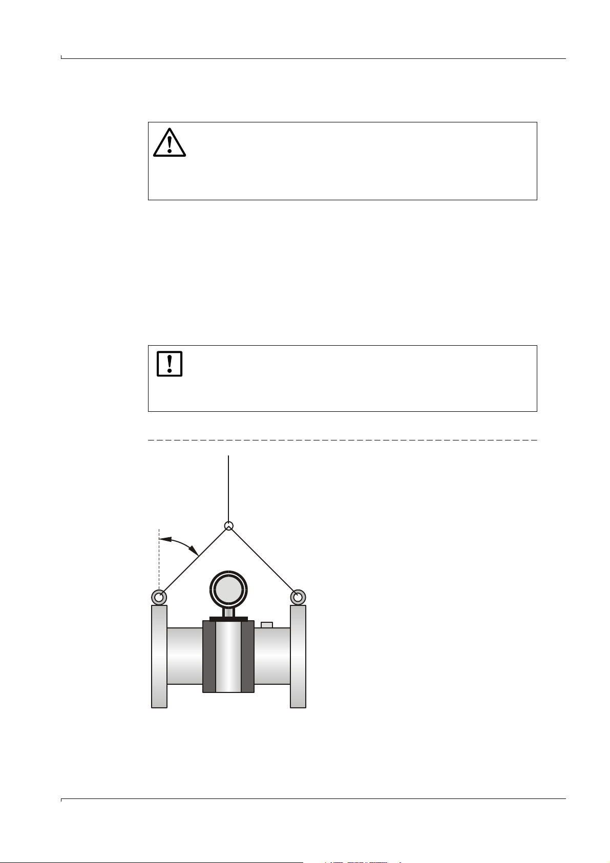
WARNING:
● Only use lifting gear and equipment (e.g. lifting straps) which is suitable for
the weight to be lifted. Max. load information can be found on the type plate
of the lifting gear.
● The eye bolts attached to the meter body are suitable for the transport of
the measuring device. However, additional loads (e.g. blind covers, filling
for pressure tests or associated piping) must not be lifted and transported
together with the measuring system without the use of additional support
from the lifting gear.
● Never attach lifting gear to the signal processing unit or its mounting
bracket and avoid contact between these parts and the lifting gear.
1.7 Environmental information and instructions for disposal
The FLOWSIC600 components are easily disassembled and do not contain toxic,
radioactive or any other enviromentally hazardous materials. The instrument consists
primarily of steel, stainless steel, plastic and aluminium, and consequently there are few
restrictions for disposal. Only the printed-circuit boards must be disposed of as electronic
scrap.
FLOWSIC600 · Operating Instructions · 8010458 V 2.0 · © SICK MAIHAK GmbH 11
Page 12

Important Information
12 FLOWSIC600 · Operating Instructions · 8010458 V2.0 · © SICK MAIHAK GmbH
Page 13

Product Description
FLOWSIC600
2 Product Description
System Components
Operating States and Signal Output
MEPAFLOW600 CBM
FLOWSIC600 · Operating Instructions · 8010458 V 2.0 · © SICK MAIHAK GmbH 13
Page 14
Product Description
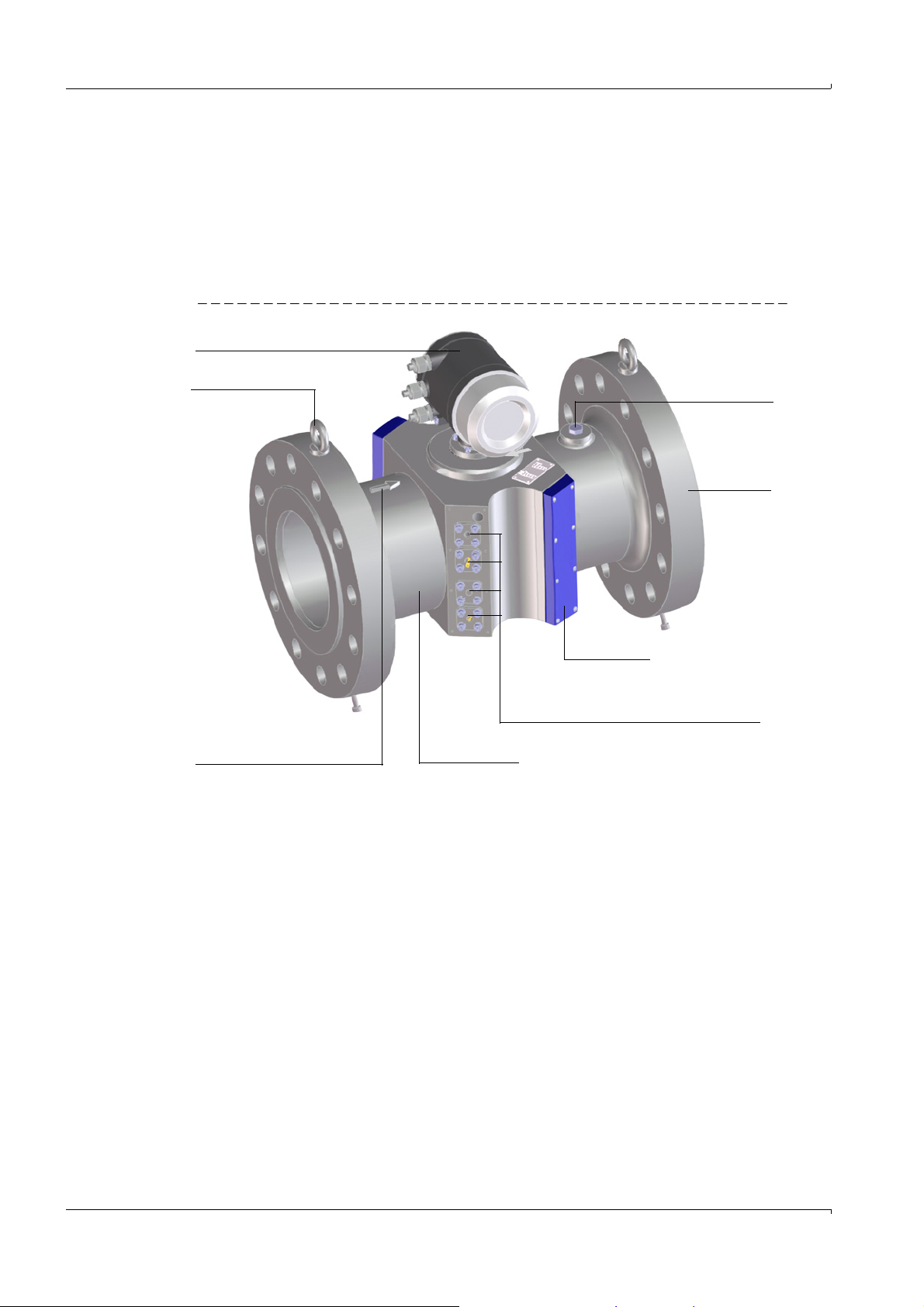
Meter body
Cover cap
Pressure tap
Flange
SPU
Hoisting eye
Position of the ultrasonic transducers
(cover cap taken off)
Marking for direction of
flow (forward)
2.1
System Components
The FLOWSIC600 measuring system consists of the following hardware components:
● Meter body
● Ultrasonic transducers
● Signal processing unit SPU
The MEPAFLOW600 CBM software is the user interface used to facilitate operation,
configuration and diagnosis (see
Figure 1 FLOWSIC600
→
pg.20, 2.3).
2.1.1
Meter body
The meter body consists of a mid section for mounting the ultrasonic transducers, with
flanges on either end. For meter sizes up to 24“, the body is made of a single-piece casting,
which is machined on precision equipment to ensure high reproducibility of the geometric
parameters. For meters larger than 24“ the body is made of a single-piece casting or
forged or the flanges are welded onto the machined mid section.
The internal diameter, design of the sealing surface, and standard dimensions of the
flanges are in accordance with the specifications in the key code. The meter body material
is chosen to suit customer requirements. Standard meter bodies are available in carbon
steel, Low Temperature Carbon Steel and stainless steel.
The meter bodies can be delivered in several nominal sizes (see
14 FLOWSIC600 · Operating Instructions · 8010458 V2.0 · © SICK MAIHAK GmbH
→
pg.82, 7.1.3).
Page 15
Product Description
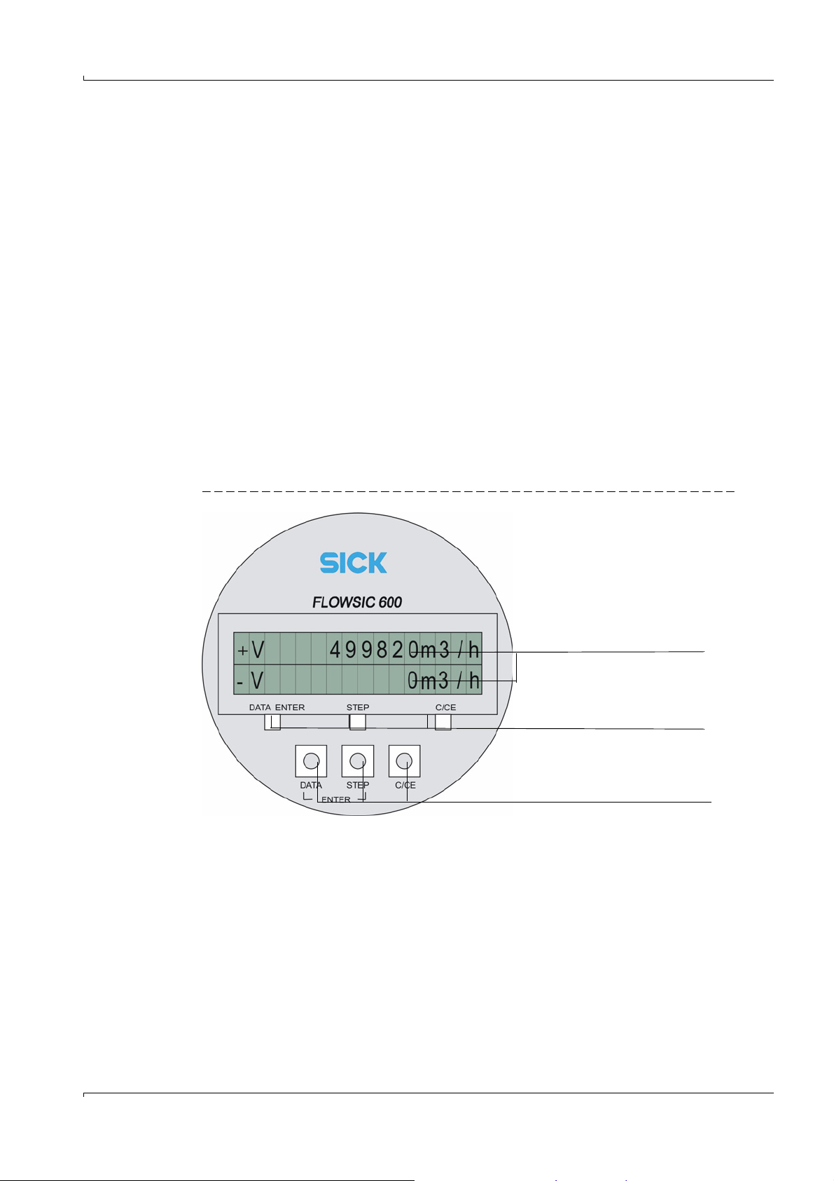
Measured values
Control buttons for the magnetic pen
Control buttons for manual use
2.1.2
Ultrasonic transducers
The FLOWSIC600 ultrasonic transducers are optimized to suit the application
requirements. The high quality of the transducer design provides the basis for accurate
and highly stable propagation time measurements with nanosecond precision. These
transducers are of an intrinsically safe design (category “ia“).
2.1.3 Signal processing unit
The SPU contains all the electrical and electronic components for controlling the ultrasonic
transducers. It generates transmission signals and analyzes the received signals to
calculate the measuring values. The SPU also contains several interfaces for
communication with a PC or standardized process control system.
The volume counters, errors, warnings, and system events are stored in a non volatile data
memory (FRAM) together with a time stamp (Logbooks
counter readings that were last saved are restored as the start values for the volume
counters. The FRAM backup provides an unlimited number of writing cycles and protects
the saved data for at least 10 years.
The SPU is equipped with a front panel containing a two-line LCD to display current
measured values, diagnostics and logbook information (
displayed can be selected using a magnetic pen without removal of the front cover . The
MEPAFLOW600 CBM software provides a more user-friendly way to display the information.
Figure 2 FLOWSIC600 front panel LCD
→
pg.86, 7.2.) On system restart, the
→
Figure 2). The values to be
The power supply and interface terminals are located on the back of the SPU in a separate
terminal section of the enclosure (
→
pg.36, 3.4.4).
The electronics are mounted in the SPU enclosure certified to EN 60079-1 or IEC 60079-1
with protection type “d“ (flameproof enclosure). The transducer circuits are of an
intrinsically safe design (category “ia“).
FLOWSIC600 · Operating Instructions · 8010458 V 2.0 · © SICK MAIHAK GmbH 15
Page 16

Product Description
2.2
Operating Modes, Meter States and Signal Output
The FLOWSIC600 has two operating modes (→2.2.1):
● Operation Mode
● Configuration Mode
In the Operation Mode the meter can have the following Meter states (
● Measurement valid
● Check request
● Measurement invalid
2.2.1 Operation Mode and Configuration Mode
The meter can be operated by the user in two modes: Operation or Configuration.
Operation Mode
In the Operation Mode, the meter runs in one of the aforementioned three Meter states,
depending on the measuring conditions.
Configuration Mode
The Configuration Mode is used to modify parameters that directly influence the
measurement and to test the system and output signals. The Configuration Mode forces
the meter into the status “Measurement invalid”. The digital output “Measurement valid” is
deactivated in Configuration Mode because invalid measured values may be produced.
The system continues operation using the current sample rate and executes all
calculations as in the Operation Mode. Frequency output and analog output may represent
test values and do thus not necessarily indicate measured values. Any parameter
modifications are applied immediately to the running calculations, with the exception of
the sample rate and baud rate of the MODBUS interface/device address.
→
2.2.2):
If the meter is in Configuration Mode and there have been no activities either
on the LCD display or via MEPAFLOW600 CBM for more than 15 minutes, the
meter automatically switches to Operation Mode.
Tes t Cycl e
The test cycle can be activated for a measuring path by setting the corresponding control
bit in the System Control Register (#3002) (the setting can be carried out on the
“Parameters” page in MEPAFLOW600 CBM). In a test cycle, the transmitted signal is fed to
the receiver signal amplifier of the measuring path through an electric attenuation unit
(transducer simulator). This function can only be activated if the system is in the
“Configuration” mode. It is used to test a path-specific electronic module.
Test cycles are automatically cancelled when leaving the “Configuration” mode.
16 FLOWSIC600 · Operating Instructions · 8010458 V2.0 · © SICK MAIHAK GmbH
Page 17

Product Description
2.2.2
2.2.2.1 Status: Measurement valid
Meter States
The “Measurement” status is the standard Meter state of the FLOWSIC600. Frequency
outputs and current output are updated cyclically and indicate the actual volume and
volumetric flow rate. In addition, the analog signal can indicate the actual flowrate,
corrected volumetric flowrate, SOS (speed of sound) or VOG (velocity of gas) The digital
output “Direction of flow” is updated in accordance with the direction of the volumetric
flow. The digital output “Valid measurement” (active) represents the status of the
measurement. Positive (forward) and negative (reverse) volumetric flow rates are
integrated and saved in separate internal memory sections.
The MODBUS interface allows the query of all parameters and signals at any time without
interfering with the function of the system.
Each measurement initiated by the system controller includes one full transit time
measurement with, and one against the direction of flow on each path. The result of each
measurement is written to a mean value memory to be used in further calculations. The
size of this memory block and thus the device response delay can be modified through the
parameter in register #3502 “AvgBlockSize”. If no result can be calculated due to poor
signal quality, this measurement is registered as an invalid attempt in the mean value
memory. The mean value is formed in a variable averaging process including all valid
measured values in the memory.
If the number of invalid measurements on a path exceeds a predefined limit (register
#3514 “Limit%Error”), the measuring system activates the “Check request” status.
2.2.2.2 Status: Check request
This status becomes active if one measuring path has failed and the adaptive path failure
compensation has been activated. The multi-path FLOWSIC600 system is able to
compensate for this failure. Measurement is continued with reduced accuracy. If a path
fails while the path failure compensation is deactivated, the measuring system will activate
the “Measurement invalid” status.
Moreover the check request status becomes active when the system alarms 2002 (“No
HART communication to temperature transmitter”), 2003 (“No HART communication to
pressure transmitter”), or 2004 (“Maximum pulse output frequency exceeded”) become
active (see table
→
pg.86, 7.2.1).
2.2.2.3 Status: Measurement invalid
If the quality of received signals is deficient in more than one measuring path, the SPU
must mark the measured value invalid and activate the meter status “Measurement
invalid”. However, the SPU will cyclically try to re-establish valid measurements. As soon as
the signal quality and number of valid measurements meet the required criteria, the SPU
will automatically change back to the “Measurement valid” or “Check request” status.
FLOWSIC600 · Operating Instructions · 8010458 V 2.0 · © SICK MAIHAK GmbH 17
Page 18
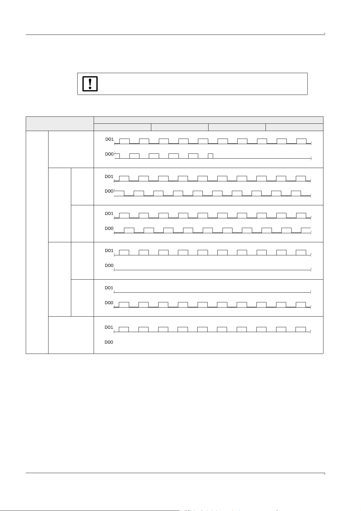
2.2.3 Pulse output and status information
NOTICE: TYPE APPROVAL
Pulse output signals can be customized as shown in the following table.
Table 1 Pulse output
Output signal / LCD / port
Pulse
output
Inverted with error
signal **
Measurement state Check request state Configuration Mode Measurement invalid*
signals
Product Description
Signal behavior
Phase
shift
Positive
flow rate
90 ° ***
Negative
flow rate
Separate
outputs
Positive
flow rate
for each
direction
***
Negative
flow rate
Single pulse output
***
* The meter can be configured to put out a fixed frequency at “Measurement invalid“. The
frequency to be put out in this case can be configured in Reg.#3034 “ErrorFreq“ (0-6 kHz).
** Default setting on delivery.
*** Optional setting on customer request.
The default setting for “Check request”, “Configuration” and “Measurement invalid” is
“normally closed”.
18 FLOWSIC600 · Operating Instructions · 8010458 V2.0 · © SICK MAIHAK GmbH
Page 19

Product Description
+V 123456 m³
-V 1234 m³
1234 m³
FLOWSIC600
Configuration
+V 123456 m³
-V 1234 m³
Tab le 2 Status output
Output signal / LCD / port
“Check request”
Status signal
“Direction of flow”
Status signal
“Warning” Status
LCD display
Serial port RS485
Measurement state Check request state Configuration Mode Measurement invalid
Status
“active / inactive” ***
Measurement valid
Status
“active / inactive” ***
Positive or negative
direction of flow
“active / inactive” ***
● Measured value, diagnosis information and parameters
● Measuring data logging, diagnosis and configuration through the MEPAFLOW600
● Connection with external process control equipment through implemented
Status
“active / inactive” ***
Compensation of path
failure
Status
“active / inactive” ***
Positive or negative
direction of flow
Status
“active / inactive” ***
Display flashing Display flashing
CBM software
MODBUS protocol (data polling)
Signal behavior
“undefined” “undefined”
“undefined” “undefined”
“undefined” “undefined”
****The “active” or “inactive” state can be assigned to the electric switch status
“normally open” or “normally closed” by configuration in the MEPAFLOW600 CBM software
(adjust settings for register #5101 on the “Parameters” page.)
The LCD display is capable of displaying measured values, parameters, messages and
other information.
A flashing letter at the upper right corner of the LCD display indicates that a logbook
contains unacknowledged logbook entries. Depending on the type of entry this will be:
● “I” for Information
● “W” for Warning
● “E” for Error
After acknowledging all new entries, the flashing letter disappears. For details see
→
pg.68,
5.4.1.
FLOWSIC600 · Operating Instructions · 8010458 V 2.0 · © SICK MAIHAK GmbH 19
Page 20

Product Description
2.3
MEPAFLOW600 CBM
Most data provided by the FLOWSIC600 (like readings, logbook entries and parameters)
can be accessed via the LCD display of the meter. However, the MEPAFLOW600 CBM
software provides a more user friendly access to diagnostic, configuration and
measurement data of the flow meter.
2.3.1 Software Installation
System requirements
● Microsoft Windows 2000/XP/Vista (later MEPAFLOW600 CBM versions will support
Windows 7 or higher)
● Min. 1 GHz CPU
● Min. 512 MB RAM
● USB- or serial interface
● Screen resolution min. 1024 x 768 pixel (optimal display resolution 1280 x 1024 pixel)
Compatibility
MEPAFLOW600 CBM can be used for all firmware and hardware versions of the
FLOWSIC600. The availability of the software features depend on the firmware version of
the connected FLOWSIC600.
Installation
A product CD containing the MEPAFLOW600 CBM software is included with the
FLOWSIC600 when it is delivered. Insert the product CD into your CD-ROM drive to install
the software. Start the file ‘FLOWSIC600_R_CD.exe‘ to install the software.
Download from www.flowsic600.com
MEPAFLOW600 CBM can be downloaded free of charge from the www.flowsic600.com
website. Select the Software tab and follow the download instructions.
20 FLOWSIC600 · Operating Instructions · 8010458 V2.0 · © SICK MAIHAK GmbH
Page 21
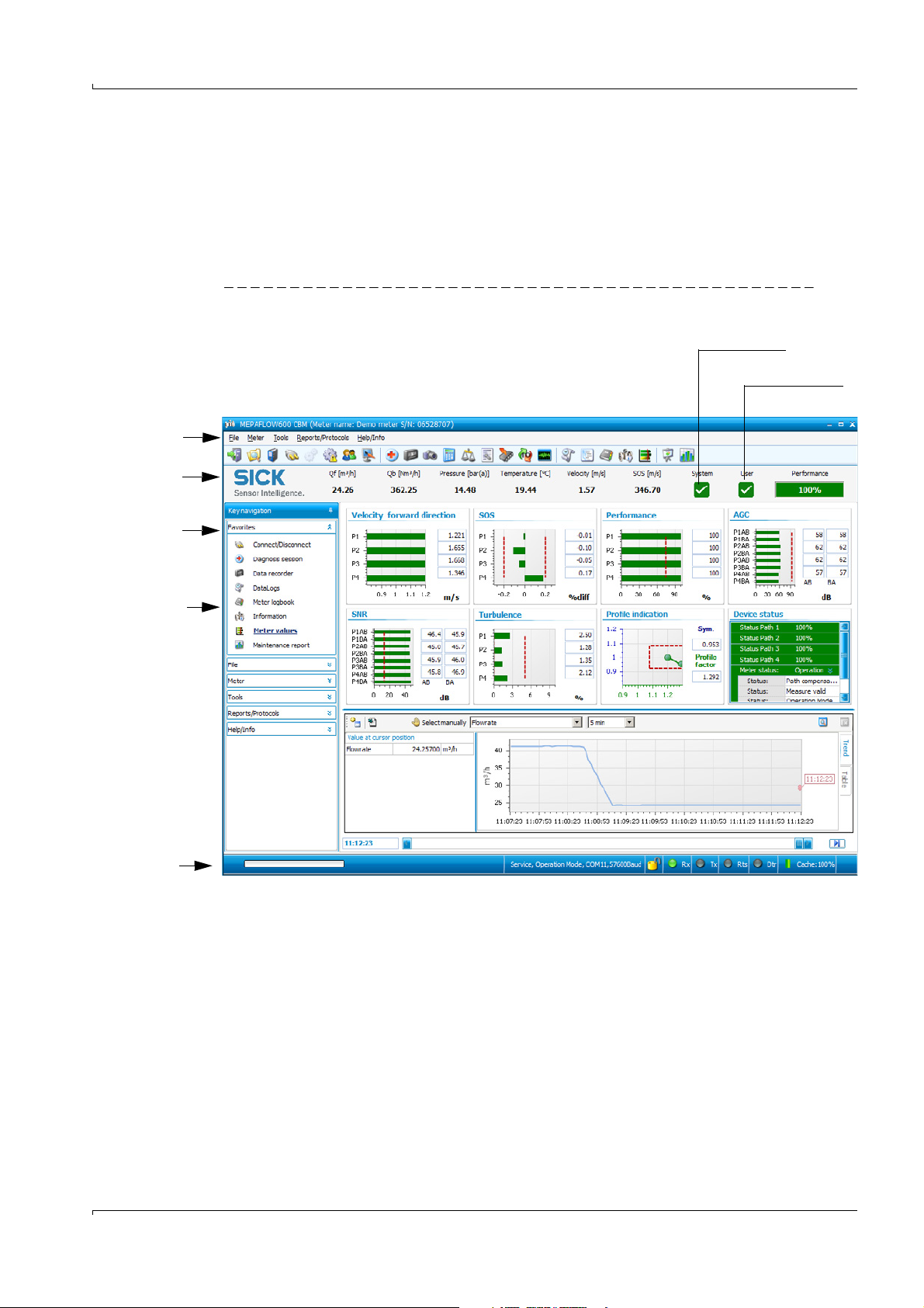
Product Description
Menu
Main system bar
with readings
Key navigation
Software features -
Status bar
Opens the “Meter
Status” page
Opens the “User
Warnings” page
2.3.2
Overview
The MEPAFLOW600 CBM software supplies a menu-based user interface with many
features for the diagnosis of the FLOWSIC600 system. It allows the access of all system
parameters, displays diagnostic information in charts and graphs, generates reports (i.e.
Maintenance reports) and data files (records, logs) which can be exported and can be used
for data analysis. It‘s meter database allows online and offline management of
parameters, reports, session files and logbooks.
Figure 3 MEPAFLOW600 CBM graphical user interface
FLOWSIC600 · Operating Instructions · 8010458 V 2.0 · © SICK MAIHAK GmbH 21
Page 22

Product Description
22 FLOWSIC600 · Operating Instructions · 8010458 V2.0 · © SICK MAIHAK GmbH
Page 23

Installation
FLOWSIC600
3 Installation
General Notes
Installation
Mechanical Installation
Electrical Installation
FLOWSIC600 · Operating Instructions · 8010458 V 2.0 · © SICK MAIHAK GmbH 23
Page 24
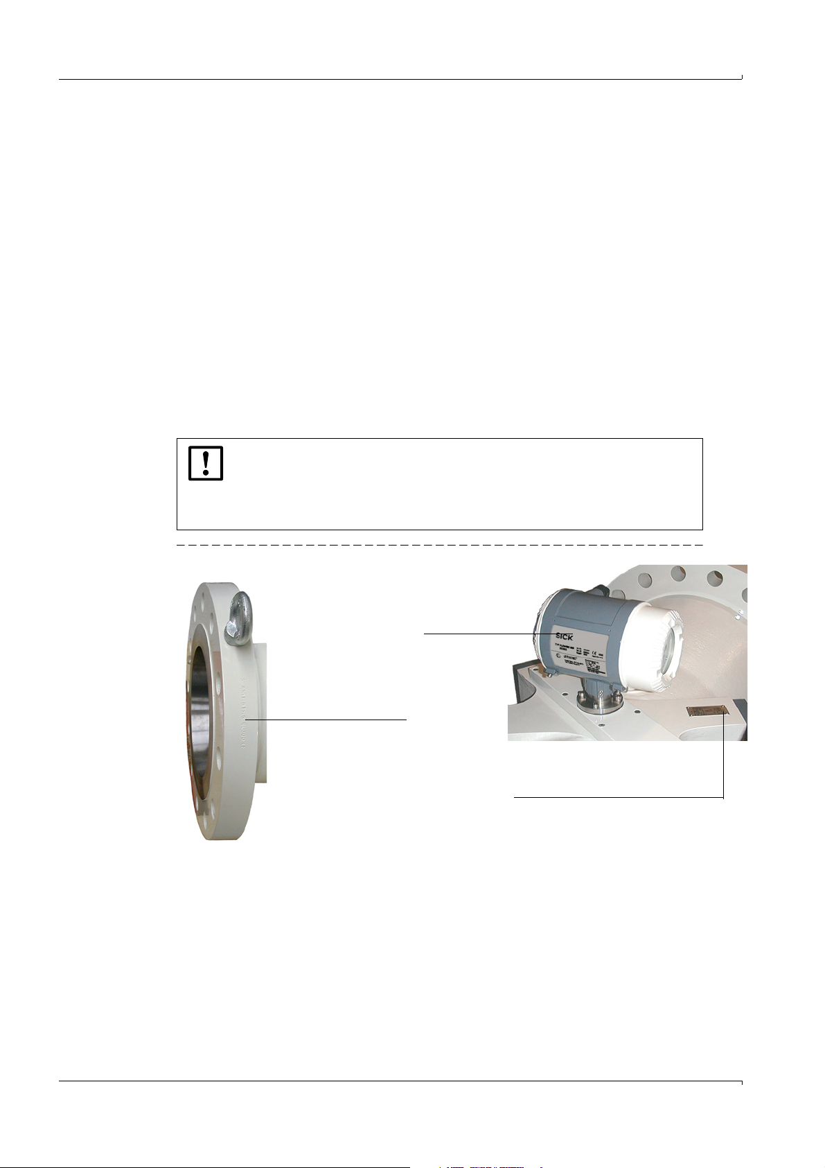
Installation
Type plate on the meter body
Flange dimensions
Main type plate on
the SPU
Main type plate, see
Drawing no. 902153 and
no. 902147 on product
CD
3.1
3.1.1 Delivery
General Notes
The FLOWSIC600 is delivered in a pre-assembled condition in a sturdy package. When
unpacking the device, check for possible damage in transit. Pay particular attention to the
interior of the meter body, any visible transducer components and the sealing surfaces on
the flanges. Any damage must be documented and reported to the manufacturer
immediately.
Also check the shipment to ensure all components are included. The standard meter
shipment is comprised of:
b
FLOWSIC600 measuring system (meter body with signal-processing unit and
transducers)
b
MEPAFLOW600 CBM control and configuration software
b
Operating instructions
b
Manufacturer Data Report (MDR)
NOTICE:
To guarantee safe and reliable operation of the measuring equipment, make
sure the actual site conditions match the information provided on the labels on
the meter body and SPU (see Fig. 5.1).
Figure 4 FLOWSIC600 labels and marks
24 FLOWSIC600 · Operating Instructions · 8010458 V2.0 · © SICK MAIHAK GmbH
Page 25
Installation
max.
45 °
3.1.2
Transport and storage
WARNING:
Only use lifting gear and load handling equipment (e.g. lifting straps) which are
suitable for the weight to be lifted. Max. load information can be found on the
type plate of the lifting gear. It is strongly recommended to use only the eye
bolts when lifting the meter by itself. To lift the FLOWSIC600 please pay
attention to Fig. 5.2.
During FLOWSIC600 transport and storage operations, make sure that:
b
The meter is firmly secured at all times
b
Measures are taken to avoid mechanical damage
b
Humidity and ambient temperature are within specified limits (see Section 2.2.4).
If the device is to be stored outside for more than one day, sealing surfaces of the flanges
and the interior of the meter body must be protected from corrosion, e.g. with Anticorit
spray (not required for stainless steel meter bodies). The same measure shall be taken if
the meter is to be stored in dry condition, but for more than a week.
NOTICE:
Due to natural temperature fluctuation in the course of a day, or if the meter is
transported to a place with different temperature and humidity conditions,
moisture may condense on any material. Carbon steel surfaces may corrode if
left unprotected.
Figure 5 Lifting requirements
FLOWSIC600 · Operating Instructions · 8010458 V 2.0 · © SICK MAIHAK GmbH 25
Page 26

Installation
3.2
Installation
Generally, the installation arrangement is specified during the project planning phase,
before installation of the system. Nominal size, material and type of flange should
therefore be in accordance with the design of the measurement facility. It is particularly
important that the meter inlet and outlet is of the same internal diameter as the adjacent
piping.
Fastening bolts, nuts and flange seals used must be suited to the operational conditions,
and comply with legal regulations and relevant standards.
Any deviation from the planned design of the FLOWSIC600 and installation
arrangement shall be agreed upon with the supplier and documented prior to
installing the meter.
3.2.1 Measuring location
General requirements:
● The FLOWSIC600 can be installed in customary straight inlet and outlet pipes. The
adjacent pipes must have the same nominal size as the meter body. The max. variation
of the internal diameter of the inlet pipe from that of the meter body is 1%. Any welding
beads and burs on the flanges of the inlet pipe shall be removed.
● The meter body may be installed in a horizontal or vertical position. In case of horizontal
installation, the meter body shall be aligned so that the planes formed by the
measuring paths are in a horizontal position. This minimizes dirt in the pipeline from
entering the transducer ports. Vertical installation is only possible if the measuring
system is used for dry, non-condensing gases. The gas flow must be free from any
foreign material, dust and liquids. Otherwise, filters and traps shall be used.
● Do not mount equipment or fittings which may adversely affect the gas flow directly
upstream the FLOWSIC600.
● Seals at the flange connections between meter body and pipeline must not protrude
into the pipeline. Any protrusion into the flowing gas stream may change the flow profile
and thus the measuring accuracy may be adversely affected.
● Pressure transmitter shall be connected to the pressure tap provided (see Fig. 2.3). The
pressure tap can be a 1/8, 1/4 or 1/2 inch NPT (female) port, depending on meter size
and customer demand.
● For the leak-proof connection on the pressure line, a suitable thread sealing agent (e.g.
PTFE tape) must be used when the pressure connection adapter is screwed in. After
Installation and Commissioning the leak-tightness must be checked. Leakages must
not be tolerated. Temperature probes shall be arranged as shown in
→
Figure 7.
→
Figure 6 and
26 FLOWSIC600 · Operating Instructions · 8010458 V2.0 · © SICK MAIHAK GmbH
Page 27
Installation
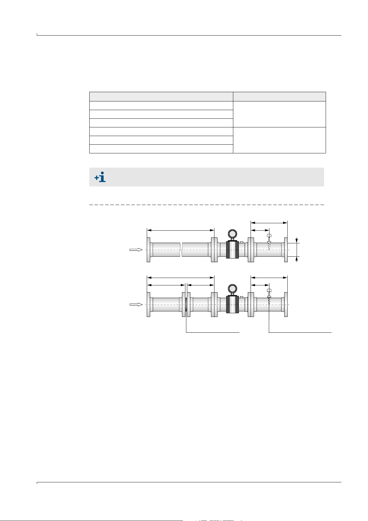
≥ 3 DN
min. 2 DN min. 2 DN 1.5 .. 5 DN
Flow conditioner Temperature measuring point
Configuration 1
Configuration 2
≥ 10 DN 1.5 .. 5 DN
FLOWSIC600 ≥ 3 DN
DN
≥ 5 DN
3.2.2
Installation configurations
The choice of the installation configuration (see →Figure6 and →Figure 7) depends on type
and extent of the flow disturbance at the installation position (according to TR G13).
Type of disturbance (distance upstream < 20 DN) Possible installation configuration
None Configuration 1 or 2
Elbow, reducer
Double elbow out of plane, T piece
Gas pressure controller with/ without noise abatement trim Configuration 2
Diffuser
Diffuser with swirling flow
When configuration 2 (with flow conditioner) is used, the velocity of gas must
not exceed 40 m/s (131 ft/s) in the pipe.
Unidirectional use
Figure 6 FLOWSIC600 installation in the pipeline for unidirectional use
FLOWSIC600 · Operating Instructions · 8010458 V 2.0 · © SICK MAIHAK GmbH 27
Page 28
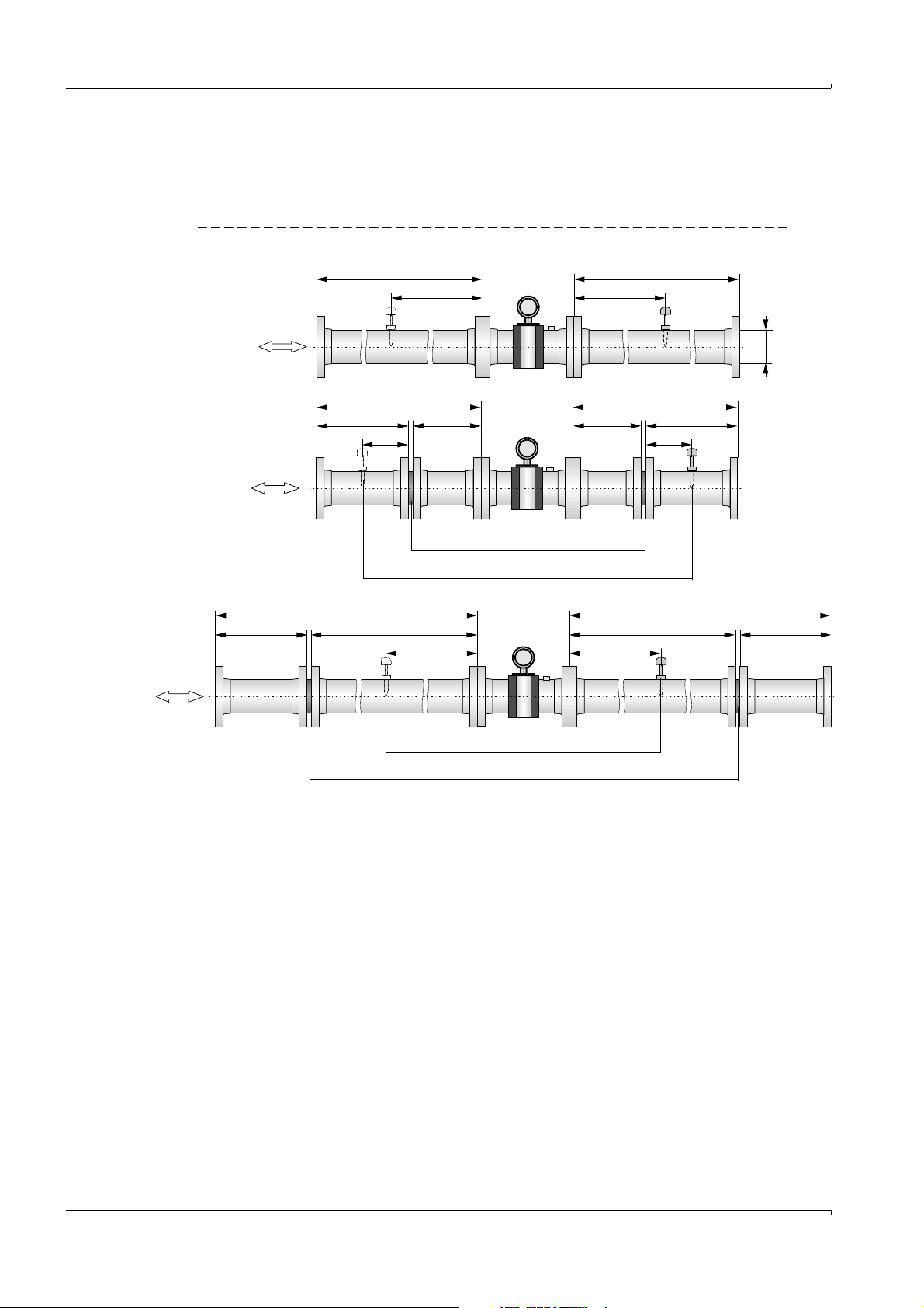
Bidirectional use
≥ 10 DN FLOWSIC600 ≥ 10 DN
min. 5 DN min. 5 DN
min. 2 DN min. 2 DN min. 2 DN min. 2 DN
1.5 .. 5 DN 1.5 ..5 DN
min. 2 DN min. 7 DN min. 7 DN min. 2 DN
Temperature measuring point
Flow conditioner
Flow conditioner
Temperature measuring point
5 ..8 DN 5 .. 8 DN
DN
Configuration 1
Configuration 2a
Applicable for meters
marked with an asterisk
(*) in
→
»Meter sizes
according to PTB
approval« (pg. 84),
Configuration 2b
Applicable for meters
marked with an asterisk
(*) in
→
»Meter sizes
according to PTB
a p p r o v a l « ( p g . 8 4 ) ,
≥ 5 DN ≥ 5 DN
≥ 10 DN ≥ 10 DN
Two straight pipes shall be installed in the inlet and outlet sections if the meter is to be
used bidirectionally. The temperature measuring point shall be disposed downstream the
FLOWSIC600, seen in the direction of predominant use (position 1 or 2 in
Figure 7 FLOWSIC600 installation in the pipeline for bidirectional use
→
Figure 7).
Installation
28 FLOWSIC600 · Operating Instructions · 8010458 V2.0 · © SICK MAIHAK GmbH
Page 29
Installation
3.3
Mechanical Installation
Work on the pipelines to prepare for the installation of the gas flow meter is not included in
the scope of delivery.
It is recommended to use the following tools, equipment and supplies for installation of the
FLOWSIC600:
● Lifting gear or fork lift (with sufficient capacity to lift meter or meter-piping assembly)
● Wrenches for tightening flanges and other fittings
● Thread seal (e.g. PTFE tape) and flange gaskets
● Bolt lubricant
● Leak detection spray
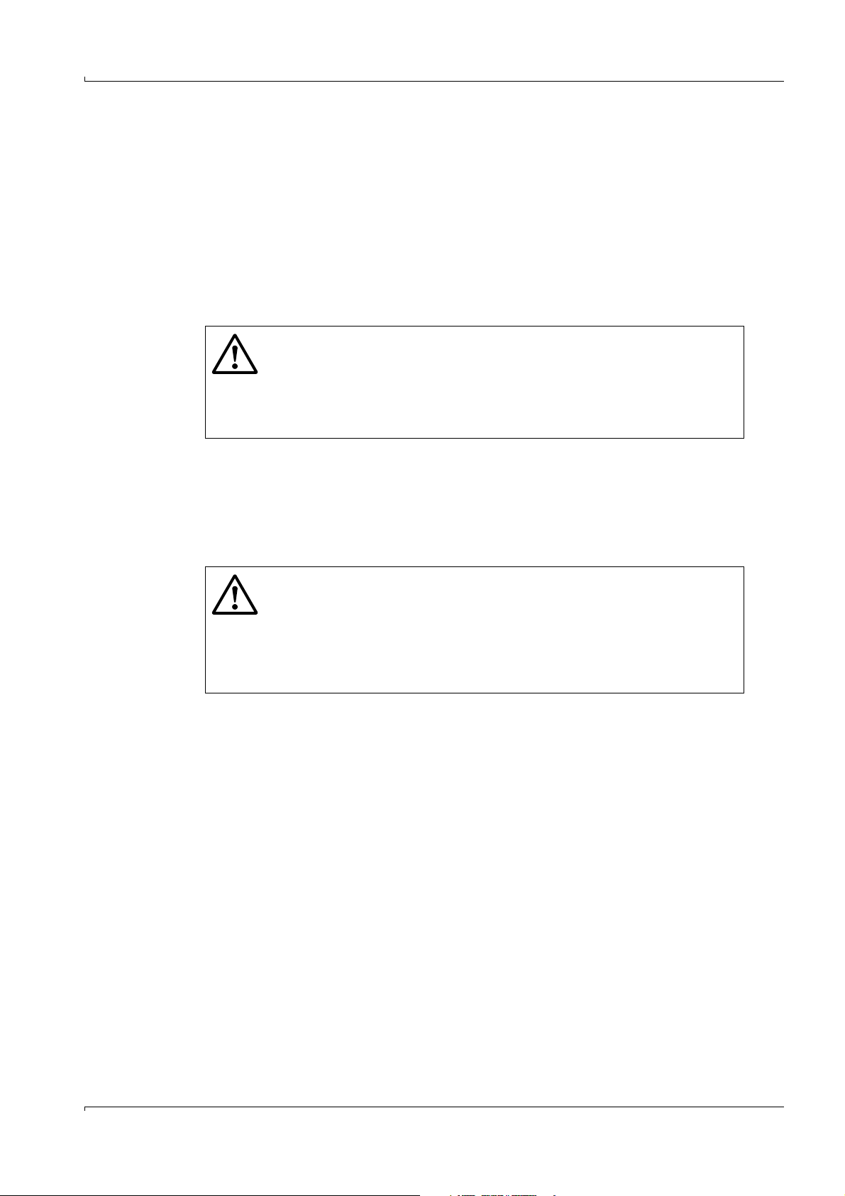
WARNING: DANGER
● Always observe the general safety regulations and safety instructions given
in Section 1 when carrying out any installation work.
● The FLOWSIC600 must only be mounted on depressurised and vented
pipelines.
● Take all necessary precautions to avoid local or plant-specific dangers.
3.3.1 Choosing flanges, seals and other parts
Use pipeline flanges, bolts, nuts, and seals that withstand the maximum operational
pressure and temperature, as well as ambient and operational conditions (external and
internal corrosion) for the flange connections. For installation lengths and flange
dimensions, see MDR).
WARNING: DANGER
● Always strictly observe the safety instructions for the installation of
pressure equipment including the connection of several pressure
components set forth in the local or national relations and standards or
Pressure Equipment Directive 97/23/EC.
● Installation staff must be familiar with the directives and standards
applicable for pipeline construction.
FLOWSIC600 · Operating Instructions · 8010458 V 2.0 · © SICK MAIHAK GmbH 29
Page 30
3.3.2 Mounting the FLOWSIC600 in the piping
An arrow on the meter body indicates the main direction of flow. It is recommended to
install the FLOWSIC600 as indicated by this arrow if the meter is to be used for
unidirectional flow applications. If the meter is to be used in the bidirectional mode, the
arrow indicates the positive direction of flow.
Installation work to be carried out
WARNING:
● The lifting eyes are designed for transporting the meter only. Do not lift the
FLOWSIC600 using these eyes when additional loads (such as blind covers,
filling for pressure tests or piping) are attached (also see
● Never attach lifting gear to the signal processing unit or its mounting
bracket and avoid contact between these parts and the lifting gear.
● The FLOWSIC600 must not turn over or start to swing while being
transported. Flange sealing surfaces, SPU housing and transducer cover
caps may be damaged when the lifting gear is not attached properly.
● Take suitable measures to prevent damage to the meter when carrying out
any other work (welding, painting) near the FLOWSIC600.
b
Position the FLOWSIC600 at the desired place of the pipeline using the lifting gear. Only
use the lifting eyes provided to lift and transport the device. If lifting straps are used,
wrap them around the meter body.
b
Check for correct seating and alignment of the flange gasket after installing the flange
bolts, but prior to tightening.
b
Align the FLOWSIC600 such that the offsets between inlet pipe, meter body and outlet
pipe are minimized.
b
Insert the remaining fastening bolts and tighten the nuts cross-wise. The tightening
torque applied must not be lower than specified in the project planning.
b
Mount the pressure sensing line between pressure tap and pressure transmitter.
b
Fill the pipeline and check the installed FLOWSIC600 and piping connections for leaks.
→
pg.25, 3.1.2)
Installation
It is recommended to perform a leak test in accordance with the relevant
regulations and standards after completion of the mechanical installation.
30 FLOWSIC600 · Operating Instructions · 8010458 V2.0 · © SICK MAIHAK GmbH
Page 31

Installation
Signal processing unit
Loosen the hexagon Position the SPUTighten the hexagon
socket head screw socket head screw
1. 2. 3.
Tool required for
loosening and
tightening the
hexagon
socket head
screw:
3 mm Allen key
3.3.3
SPU alignment
The signal processing unit (SPU) can be turned so that the display can be easily read and
that cable routing is facilitated (see
being turned by more than 330° to prevent damage to the cables that come from the meter
body.
Figure 8 Positioning the SPU.
→
Figure8). A stop on the housing prevents the SPU from
NOTICE:
Do not forget to tighten the hexagon socket head screw after positioning the
SPU.
FLOWSIC600 · Operating Instructions · 8010458 V 2.0 · © SICK MAIHAK GmbH 31
Page 32

Installation
3.4
3.4.1 General information
Electrical Installation
Pre-requisites
Wiring work (routing and connecting the power supply and signal cables), which is
necessary when installing the FLOWSIC600, is not included in the scope of delivery. The
mechanical installation described in Section
the minimum cable specification requirements set out in Section
Cable routing
b
Keep cables in conduits or laid on cable trays to provide protection from mechanical
damage.
b
Observe the permitted bending radiuses (generally, min. six times the cable diameter
for multi-conductor cables).
b
Keep all connections outside of conduits as short as possible.
WARNING: DANGER
b
Always observe the general safety regulations and safety instructions given
in Section 1 when carrying out any installation work.
b
Installation work shall only be carried out by trained staff and in
accordance with the relevant regulations issued by the operating company.
b
Take all necessary precautions to avoid local or plant-specific dangers.
→
3.3 must be completed first. Comply with
→
3.4.2.
32 FLOWSIC600 · Operating Instructions · 8010458 V2.0 · © SICK MAIHAK GmbH
Page 33

Installation
Safe area
Hazardous area
Service PC / higherlevel control system
RS485 / MODBUS
Gas volume at flowing conditions Pressure Temperature
Electronic Volume
Corrector (EVC) /
Flow Computer (FC)
FLOWSIC600
Compressibility factor Z
Heating value H
s
Gas Volume at base
conditions
Energy content
12 ... 24 V DC
(Ex i isolating transformer only
required for intrinsically safe
installation)
General connection of the FLOWSIC600
Figure 9 FLOWSIC600 connection diagram
FLOWSIC600 · Operating Instructions · 8010458 V 2.0 · © SICK MAIHAK GmbH 33
Page 34

3.4.2 Cable specifications
WARNING:
The cables must fulfill the requirements for use in hazardous areas (e.g set
forth in EN 60079-14 or other relevant standards).
Power supply 12 … 28.8 V DC
Type of cable Two conductors Connect shielding (if present) to
Min./ max. crosssectional area
Maximum cable length Depending on loop resistance;
Cable diameter 6 ... 12 mm (1/4 to 1/2 inch) Fixing range of the cable glands
Digital output / current output
Type of cable Twisted pair, shielded Connect shielding at other end to
Min./ max. crosssectional area
Maximum cable length Loop resistance under load ≤ 250 Ω
Cable diameter 6 ... 12 mm (1/4 to 1/2 inch) Fixing range of the cable glands
Specification Notes
ground terminal
0.5 mm² / 1.5 mm² (16 to 20 AWG)
Peak current 150 mA
Minimum input voltage on the
FLOWSIC600 12 V
Specification Notes
ground terminal
2 x 0.5 mm
2
(2 x 20 AWG)
Do not connect unused
conductor pairs and prevent
them from accidental short-
circuit
Installation
Serial port (RS485)
Specification Notes
Type of cable Twisted pair, shielded,
impedance approx. 120Ω
Min./ max. crosssectional area
Maximum cable length 500 m at 0.5 mm²
Cable diameter 6 ... 12 mm (1/4 to 1/2 inch) Fixing range of the cable glands
2 x 0.5 mm
1000 m at 0,75 mm² (1500 ft for 20
AWG)
2
(2 x 20 AWG)
Connect shielding at other end to
ground terminal
Do not connect unused lead
pairs and prevent them from
accidental short-circuit.
34 FLOWSIC600 · Operating Instructions · 8010458 V2.0 · © SICK MAIHAK GmbH
Page 35

Installation
3.4.3
Checking the cable loops
Check the cable loops to verify that the cables are connected correctly. Proceed as follows:
b
Disconnect both ends of the cable of the loop to be tested. This is to prevent connected
devices from interfering with the measurement.
b
Test the entire cable loop between SPU and terminal device by measuring the loop
resistance.
b
If you want to test the insulation resistance as well, the cables must be disconnected
from the electronic module before using the insulation resistance tester.
WARNING:
The test voltage applied would seriously damage the electronic module!
b
Reconnect all cables after the loop resistance test.
WARNING:
● In non-intrinsically safe installations, the Exe terminal boxes and connect/
disconnect cables must only be opened if the system is disconnected from
the power supply.
● The front cap (with display panel) must only be opened if the system is
disconnected from the power supply and only 10 minutes or more after the
system has been switched off.
● Incorrect cabling may cause failure of the FLOWSIC600. This will invalidate
warranty claims. The manufacturer assumes no liability for consequential
damage.
FLOWSIC600 · Operating Instructions · 8010458 V 2.0 · © SICK MAIHAK GmbH 35
Page 36

3.4.4 Terminal enclosure on the SPU
Open the cover
Cover
Securing clip
Cover for power
supply terminals
Cable entry for internal 10core cable
10-pole terminal block
for signal inputs and outputs
1
2
HSK-K type cable glands,
M 20 x 1.5 plastic (EU)
or ½ in NPT (North America)
Power supply
2 x 1.5 mm
2
(LiYCY or equivalent)
Digital output / current
output
4 x 2 x 0.5 mm
2
(Li2YCY [TP] or equivalent)
MODBUS
4 x 2 x 0.5 mm
2
(Li2YCY [TP] or equivalent)
Bridge
Opening the rear housing cover
b
Loosen the securing clip using a 3 mm Allen key.
b
Turn the rear housing cover counter-clockwise and take it off.
NOTICE: Lubricant
Only use LOCTITE 8156 as lubricant for front and rear housing cover.
A schematic wiring diagram is provided on the inside of the rear housing cover.
Figure 10 SPU housing
Installation
Figure 11 Terminal box on the rear of the SPU (see Section →3.4.2 for North American wiring specification equivalents)
36 FLOWSIC600 · Operating Instructions · 8010458 V2.0 · © SICK MAIHAK GmbH
Page 37
Installation
Terminal box
Power supply Field connections (10-pole terminal block)
PA
PA
Figure 12 Terminal assignment for use in safe areas
Terminals 2 and PE are bridged internally, i.e. there is no insulation between
PE and negative potential (see
→
Figure 11).
FLOWSIC600 · Operating Instructions · 8010458 V 2.0 · © SICK MAIHAK GmbH 37
Page 38

3.4.5 Operating the FLOWSIC600 in safe areas
Assign the terminals in the SPU terminal box (see →Figure 12) in accordance with the
following table.
No. Connection for Function Termina l Value Notes
1 Power supply 1+, 2- 12 ... 24 (+20 %) V DC
2 Digital output DO 0
(HF 2)
Passive 31, 32 f
= 6 kHz, pulse duration 0.05 s - 1 s
max
Range:
Variable number of pulses per volume unit
“closed”:
0 V ≤ U
≤ 2 V, 2 mA ≤ I
CE L
≤ 20 mA (L=Low)
CE L
With NAMUR
contact for
connection to
switching amplifier
(to DIN 19234)
“open”:
3Serial port MODBUS
(RS485)
4 Digital output DO 1
Passive 51, 52 f
(HF 1)
16 V ≤ U
33, 34 9600 Baud, 8 data bits, no parity, 1 stop bit Baud rate to be set
= 6 kHz, pulse duration 0.05 s - 1 s
max
Range:
Variable number of pulses per volume unit
“closed”:
0 V ≤ U
≤ 30 V, 0 mA ≤ I
CE H
≤ 2 V, 2 mA ≤ I
CE L
≤ 0.2 mA (H=High)
CE H
≤ 20 mA (L=Low)
CE L
through software
With NAMUR
contact for
connection to
switching amplifier
(to DIN 19234)
“open”:
16 V ≤ U
≤ 30 V, 0 mA ≤ I
CE H
≤ 0.2 mA (H=High)
CE H
5 Digital output DO 2 Passive 41, 42 “closed”:
0 V ≤ U
“open”:
16 V ≤ U
≤ 2 V, 2 mA ≤ I
CE L
≤ 30 V, 0 mA ≤ I
CE H
≤ 20 mA (L=Low)
CE L
≤ 0.2 mA (H=High)
CE H
“Check request” (default)
6 Digital output DO 3 Passive 81, 82 “closed”:
0 V ≤ U
≤ 2 V, 2 mA ≤ I
CE L
≤ 20 mA (L=Low)
CE L
“open”:
16 V ≤ U
“Direction of flow” (default)
≤ 30 V, 0 mA ≤ I
CE H
≤ 0.2 mA (H=High)
CE H
(alternative “Warning”)
Alternative assignment with second
serial port (RS485)
9600 Baud, 8 data bits, no parity, 1 stop bit Baud rate to be set
through software
Installation
38 FLOWSIC600 · Operating Instructions · 8010458 V2.0 · © SICK MAIHAK GmbH
Page 39

Installation
3.4.6
Operation in hazardous areas (Directive 94/9/EC (ATEX)1)
The power supply and field connections are designed with the increased type of protection
(“e“). The transducer connections are of an intrinsically safe design (“ia“).
All screw-type terminals as well as air gaps and creepage distances of the FLOWSIC600
comply with EN 60079-7.
Connection characteristics
Power supply connection Field connections
Separate terminal box, separated from the field
connections with partition wall in the housing
and cover to EN 60079-11.
Cable routing via Exe cable gland, M5 ground
terminal integrated into housing section (cast-on
part).
Connection options
The protection concept for the FLOWSIC600 permits the following connection options:
● Non intrinsically safe power supply connection and field connections with increased
type of protection (“e“)
● Intrinsically safe power supply connection and field connections (“i“)
● Non intrinsically safe power supply connection with increased type of protection (“e“),
while the field connections are intrinsically safe (“i“)
The user shall decide which option is to be used, taking into account local / national
regulations and standards or EN 60079-14.
A combination of intrinsically safe and non-intrinsically safe circuits is not permitted in the
terminal box for the field connections.
The rated voltage of non-intrinsically safe circuits is U
Separate terminal box, separated from the
power supply connections with partition wall in
the housing and cover to EN 60079-11.
Cable routing via 2x Exe cable gland
= 253 V.
M
1 For use in the US and Canada see Control drawings 781.00.02 page 1 to 3.
FLOWSIC600 · Operating Instructions · 8010458 V 2.0 · © SICK MAIHAK GmbH 39
Page 40

Installation
Requirements regarding cabling in hazardous areas (ATEX)
● The cables must fulfill the requirements set forth in EN 60079-14.
● Cables that are subject to exceptional thermal, mechanical, or chemical loads must be
specially protected (e.g. laid in open-ended conduits).
● Cables that are not installed fire proof must be fire retardant according to IEC 60332-1.
● Ferrules must be attached to the wire ends to ensure that they do not split up.
● The applicable requirements regarding air gaps and creepage distances must be
observed in accordance with EN 60079-7. The available air gaps and creepage
distances in the terminal box must not be reduced when connecting the cables.
● Unused cable glands must be replaced by the Exe plugs included in the delivery.
● The equipotential bonding must be in accordance with EN 60079-14.
● The meter body and SPU housing must be connected to the potential equalizer. In
intrinsically safe circuits, provide equipotential bonding along the wiring runs of the
current outputs.
● The applicable national specifications shall also be observed.
Operation of ultrasonic sensors in Zone 0
The ultrasonic transducers are suitable for the operation in Zone 0 at atmospheric
conditions, i.e. ambient temperature -20 °C to 60 °C and ambient pressure 0.8 bar to 1.1
bar(a). If ultrasonic transducers with titanium housing are to be used in Zone 0, it must be
assured that the medium does not transport solid parts (like dust or other particles) which
could cause an ignition hazard.
After installation and after every deinstallation and following reinstallation of the ultrasonic
transducers, the seal effect must be appropriately checked. During the operation the leak
tightness must be periodically checked and the sealing must be renewed if necessary.
After deinstallation and before every reinstallation the sealings must be renewed according
to the original assembly. Sealings can be ordered from SICK (provide article number and
serial number from type plate).
Terminal assignment
The terminal assignment in the SPU terminal box (see
→
Figure 12) is the same as for the
installation of the FLOWSIC600 in non-hazardous areas (see table in Section
NOTICE:
The protective conductor must not be connected within the hazardous area.
For measurement reasons, the equipotential bonding must, as far as possible,
be identical to the pipeline potential or protective ground/earth. Additional
grounding with the protective conductor via the terminals is not permitted!
→
3.4.5).
40 FLOWSIC600 · Operating Instructions · 8010458 V2.0 · © SICK MAIHAK GmbH
Page 41

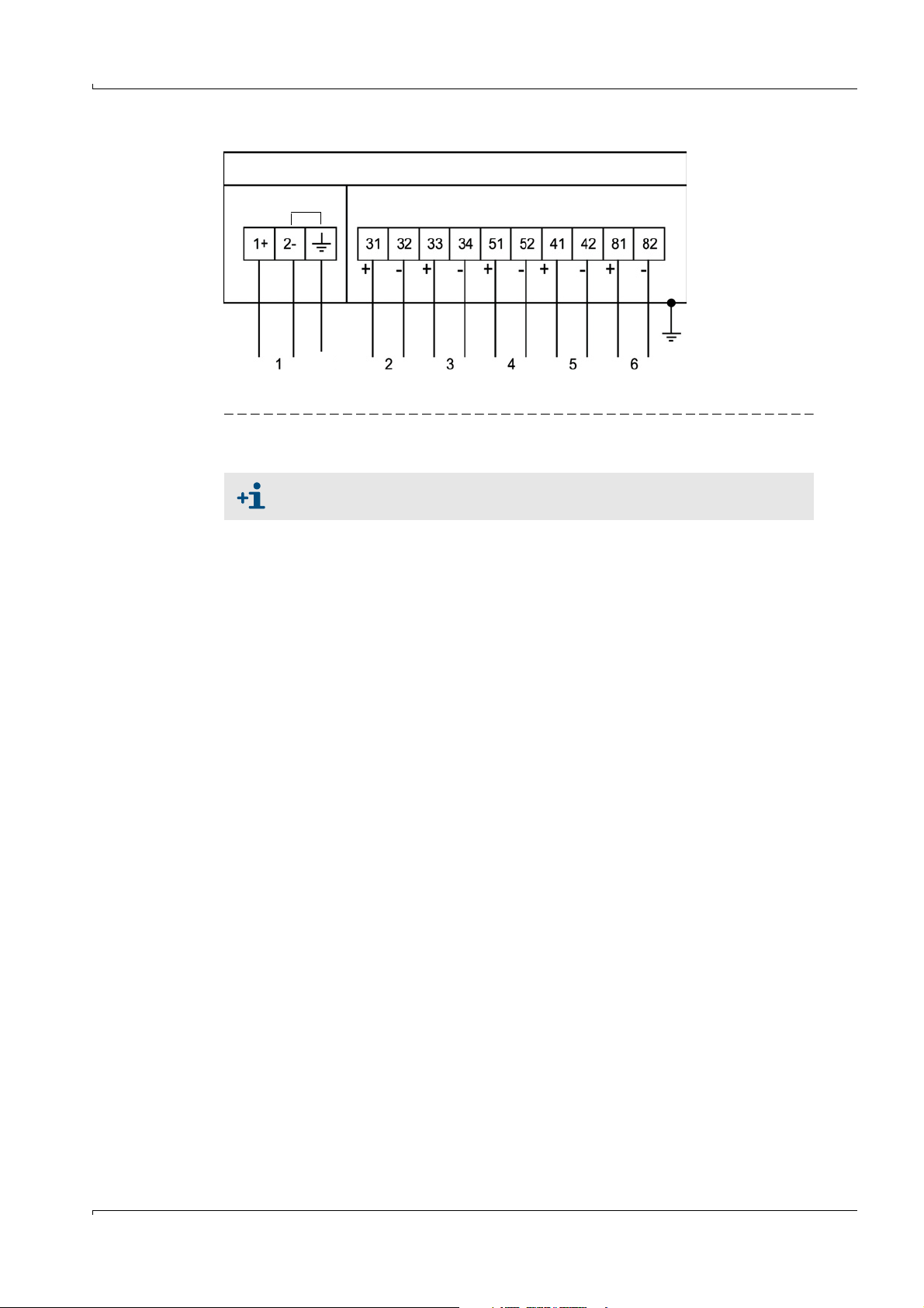
Installation
1+
2-
31
32
33
34
51
52
41
42
81
82
Aux. power
PA
Digital output
RS485
Digital output
Digital output
Digital output
Power supply
Field connections
Terminal box “e”, “i”
Signal processing unit
(SPU)
Pressure-resistant
space “d”
Meter body
Ultrasonic transducers “ia”
PA
Notes for safe operation in hazardous areas
Approval of the ultrasonic transducers in zone 0 is only valid for operation
under atmospheric conditions.
● Type of explosion protection: II 1/2G Ex de ib [ia] IIC T4 or II 2G Ex de ib [ia] IIA T4
● Ambient temperature:-20°C to +60°C
In the extended temperature range from -40 °C to +60 °C, metal cable glands shall be
used.
● The cable glands included in the delivery are black. If terminals are assigned with
intrinsically safe circuits, it is recommended to replace the black ones with the lightblue (RAL 5015) cable glands provided.
● The type of protection for the field connections and power supply connection is
determined by the external circuits that are connected (for options see “Connection
options“ above).
● Safety-relevant data for intrinsically safe circuits is provided in the EC Type Approval
Certificate.
● Ensure that the cover on the power supply connection is properly sealed. In intrinsically
safe installations, the terminal box can be opened and cables connected and
disconnected while the system is live. In this case it is also allowed to connect or
disconnect cables from each other when attention is paid to the safe separation of the
curcuits.
● If the meter body is insulated, the insulation thickness must not exceed 100 mm. The
SPU housing must not be insulated.
WARNING:
Always observe the temperature specifications for use in hazardous areas.
Figure 13 FLOWIC600 components and their type of protection
FLOWSIC600 · Operating Instructions · 8010458 V 2.0 · © SICK MAIHAK GmbH 41
Page 42

Safety-relevant data of inputs and outputs
Output circuit Intrinsically safe Ex ia/ib IIA/IIb/ IIC Non-
intrinsically
safe
V
= 253 V
M
Active current output
Terminals 31/32
V
= 22.1V VB = 18 V
O
I
O
P
O
[mA] [mW] C
Ex ia/ib IIA Ex ia/ib IIB Ex ia/ib IIC
[nF] LO [mH] CO [nF] LO [mH] CO [nF] LO [mH]
O
IB = 35 mA
Hardware variant 1-5 155 857 4.1 7 163 1
Hardware variant 687481270.54771
Characteristic curve: linear
or for connection to certified intrinsically safe circuits with the following maximum values:
U
= 30 V
I
I
= 100 mA
I
P
= 750 mW
I
Internal capacity: CI = 4 nF
Internal inductance: negligible
Digital output
Terminals 51/52
Terminals 41/42
Terminals 81/82
For connection to certified intrinsically safe circuits with the following maximum values:
U
= 30 V
I
I
= 100 mA
I
P
= 750 mW
I
U
= 30 V
B
IB = 100 mA
Internal capacity: CI = 4 nF
Internal inductance: negligible
RS485
Terminals 33/34
Terminals 81/82
Characteristic curve: linear
U
= 5.88 V
o
I
= 313 mA
o
P
= 460 mW
o
Co = 1000 μF for IIA resp. 43 μF for IIC
L
= 1.5mH for IIA resp. 0.2 mH for IIC
o
U
= 5V
B
IB = 175 mA
or for connection to intrinsically safe circuits with the following maximum values:
U
= 10 V
I
I
= 275 mA
I
P
= 1420 mW
I
Internal capacity: CI = 4 nF
Internal inductance: negligible
Ultrasonic transducer
connections
(for connecting SICK
ultrasonic transducers
only)
Ex ia/ib IIA Ex ia/ib IIB Ex ia/ib IIC
Characteristic curve: linear
Max. transmission voltage: U
Short-circuit current: I
Internal capacity: negligible
Internal inductance: L
= ±60.8 V
o
= ±92 mA
o
P
= 1399 mW
o
= 20.6 mH
i
U
= ±51.2 V
o
I
= ±77 mA
o
P
= 556 mW
o
negligible
L
= 15.5 mH
i
U
= ±38.9 V
o
I
= ±59 mA
o
P
= 556 mW
o
negligible
L
= 6.7 mH
i
Installation
42 FLOWSIC600 · Operating Instructions · 8010458 V2.0 · © SICK MAIHAK GmbH
Page 43

Commissioning
FLOWSIC600
4 Commissioning
General Notes
Connecting the FLOWSIC600 to a PC or Laptop
Connecting to the FLOWSIC600 with MEPAFLOW600 CBM
Identification
Field Setup
Function Test
Activation of Path Compensation
Sealing
FLOWSIC600 · Operating Instructions · 8010458 V 2.0 · © SICK MAIHAK GmbH 43
Page 44

Commissioning
4.1
General Notes
Before commissioning, all activities described in the chapter →»Installation« must be
completed. It is recommended to use a laptop/PC with installed MEPAFLOW600 CBM
software for the commissioning (
The FLOWSIC600 is ’wet’ or ’dry’ calibrated when delivered to the end user. The ’dry’
calibration contains the 3-D measurement of the meter body, zeroflow and speed of sound
test, and other system specific inspections/tests which belong to the manufacturing and
quality assurance process. The ’wet’ calibration is performed at a flow calibration test
stand (calibration test facility).
All parameters, determined by the aforementioned tests, as well as design specific data
are preset and stored in the FLOWSIC600 in a non-volatile memory before delivery. The
design-specific data which is known before manufacturing the device will not be changed
during commissioning. This is of special importance if the FLOWSIC600 is officially sealed
after an authorized flow calibration. Generally, the parameters are protected by a
password. Additionally a Parameter write lock in the SPU prevents custody relevant
parameter changes.
NOTICE: Type A pprova l
If the FLOWSIC600 is to be used for custody transfer applications, each
change of parameters and of the Parameter write lock has to be agreed to by
the applicable national authorities.
In all other cases the output parameters of the FLOWSIC600 can be adapted on site by
trained staff.
Commissioning the FLOWSIC600 involves the following steps, no matter whether the
device is installed at a test facility or at the final measuring location:
● Connecting the FLOWSIC600 to a PC or Laptop (
● Connecting to the FLOWSIC600 with MEPAFLOW600 CBM (
● Identifikation (
● Field setup (
● Function test (
● Activation of path compensation (
● Sealing (
→
pg.52, 4.4)
→
pg.53, 4.5)
→
pg.55, 4.6)
→
pg.60, 4.8).
→
pg.47, 4.3).
→
pg.59, 4.7)
→
pg.45, 4.2)
→
pg.47, 4.3)
44 FLOWSIC600 · Operating Instructions · 8010458 V2.0 · © SICK MAIHAK GmbH
Page 45

Commissioning
Terminals*
1:1
Connection cable
COM
port
(9-pole)
Fieldbus Isolating
Repeater
Type 9185
(Company “Stahl”)
Ex-Zone
Safe-Zone
4.2
4.2.1 Connecting the FLOWSIC600 via RS485 / RS232 cable
Connecting the FLOWSIC600 to a PC or Laptop
Interface sets for the connection of the FLOWSIC600 with a PC via serial- or
USB-interface can be ordered from SICK. See
→
pg.46, Table 3.
The FLOWSIC600 serial interface conforms with the RS485 standard. An RS485 /RS232
cable and a 1:1 interface cable (pin 2 – pin 2 and pin 3 – pin 3) are required for data
transfer to PC or laptop (see
→
Figure14). Because MEPAFLOW600 CBM, the operation and
diagnosis software for the FLOWSIC600, does not support RTS/CTS data transfer, the
adapter must be able to distinguish between transmission and reception mode
automatically. We, therefore, recommend the use of a serial interface set available from
SICK.
Figure 14 Wiring example of “MEPA interface set RS485 / RS232” intrinsically safe for DIN rail mounting
*Possible terminals for the RS485 connection are:
● 33 (+) and 34 (-)
● 81 (+) and 82 (-)
FLOWSIC600 · Operating Instructions · 8010458 V 2.0 · © SICK MAIHAK GmbH 45
Page 46

Commissioning
A / RxD
B / TxD
USB
USB
USB
Terminals*
Connection cable
Safe-Zone
4.2.2 Connecting the FLOWSIC600 via RS485/USB converter
If the PC/laptop does not offer a RS232 serial interface, a USB interface can be used. An
appropriate USB converter is necessary to transform the signal for the RS485 device
interface. The USB converter available through SICK contains a CD-ROM with a software
driver which must be installed before an online connection between the FLOWSIC600 and
the MEPAFLOW600 CBM software can be established.
Figure 15 Wiring example of “MEPA interface set RS485/USB” (Converter, Cable, Terminal plug, CD-ROM with
software driver), non-intrinsically safe
*Possible terminals for the RS485 connection are:
● 33 (+) and 34 (-)
● 81 (+) and 82 (-)
Table 3 Interface sets for the connection of the FLOWSIC600 to a PC
Description Part Number
“MEPA interface set RS485 / RS232” intrinsically safe for DIN rail mounting 2033410
“MEPA interface set RS485/USB” (Converter, cable, terminal plug, CD-ROM with
software driver), non-intrinsically safe
6030669
46 FLOWSIC600 · Operating Instructions · 8010458 V2.0 · © SICK MAIHAK GmbH
Page 47

Commissioning
Program Group
Desktop Icon
4.3
4.3.1 Starting MEPAFLOW600 CBM
Connecting to the FLOWSIC600 with MEPAFLOW600 CBM
The MEPAFLOW600 CBM software is provided on the product CD shipped with the meter. It
can also be downloaded from www.flowsic600.com. See
the installation.
b
After successful installation, start the MEPAFLOW600 CBM by selecting the
“MEPAFLOW600 CBM” entry in the program group created during installation, or by
double-clicking on the desktop icon.
Figure 16 MEPAFLOW600 CBM program group and desktop icon
→
pg.20, 2.3.1 for more details on
FLOWSIC600 · Operating Instructions · 8010458 V 2.0 · © SICK MAIHAK GmbH 47
Page 48

4.3.2 Choosing an User Access Level
b
After starting MEPAFLOW600 CBM, the “Connect / Disconnect” page appears with the
Password dialog window. (
b
Choose a User access level, activate the corresponding radio button, enter the
→
Figure 17)
password and click the “OK” button.
User access level Password
Operator No password required
Authorized operator “sickoptic”
Service See Service Manual
Figure 17 MEPAFLOW600 CBM “Connect / Disconnect” page with Password dialog window
Commissioning
b
The Password dialog disappears and the “Connect / Disconnect” page with a list of all
meters in the meter database appears.
4.3.3 Creating a new meter entry in the meter database
New meter entries can be created, whether the corresponding meter is
connected to the PC or not. If the meter is connected, MEPAFLOW600 CBM
loads all available parameters from the meter. If the meter is not connected,
an initial master data set is created from the information the user enters.
b
Create a new meter entry in the meter database by clicking the “New” button. Then
follow the instructions on screen.
48 FLOWSIC600 · Operating Instructions · 8010458 V2.0 · © SICK MAIHAK GmbH
Page 49

Commissioning
4.3.4
Online Connection: Direct Serial
b
Choose a meter and click the “Direct serial” to establish a serial connection to a meter
which is connected to the PC.
b
Specify the appropriate connection settings in the Connection settings window
(
→
Figure18) and click the “Connect” button to establish an online connection to the
meter. If the connection fails, see
Figure 18 Connection settings
→
pg.78, 6.4 for troubleshooting.
The parameters shown in →Figure 18 are default values - except for the serial
COM port which has to be individually configured.
b
After the connection has been established, MEPAFLOW600 CBM displays the start
page (can be specified in the Program settings) and the current readings from the
meter.
FLOWSIC600 · Operating Instructions · 8010458 V 2.0 · © SICK MAIHAK GmbH 49
Page 50

4.3.5 Online Connection: Ethernet
The FLOWSIC600 can be connected to a network via Ethernet with an according adapter.
This adapter translates the meter MODBUS communication (ASCII or RTU) to MODBUS TCP.
MEPAFLOW600 CBM supports the MODBUS TCP protocol.
Requirements
● The Ethernet connection requires firmware V3.3.05 or higher installed on
the FLOWSIC600, which provides the necessary Generic MODBUS protocol
on the RS485 interface.
● The FLOWSIC600 must be connected to a MODBUS ASCII/ MODBUS RTU to
MODBUS TCP adapter, which is connected to a network via Ethernet and
receives a - preferably permanent - IP address.
● The PC with MEPAFLOW600 CBM V1.0.46 or higher installed must be
connected to the network and have uninhibited access to this IP address.
Preparations for Online Connections via Ethernet
b
Make sure one of the serial ports (terminals 33/34 or 81/82) of the
FLOWSIC600 is configured to use Generic MODBUS RTU or Generic
MODBUS ASCII (NOT a SICK MODBUS protocol).
b
Connect a MODBUS RTU/MODBUS ASCII to MODBUS TCP adapter to the
serial port according to the manual of the adapter.
b
Connect the adapter cable to your network.
b
Make sure the network assigns a permanent IP address to the adapter.
b
Configure the adapter to the network settings (IP address / protocol /
baudrate / gateway etc.) that you want to use (refer to adapter manual).
b
Make sure the PC with MEPAFLOW600 CBM has access to the adapters IP
address.
b
Make sure you know the MODBUS bus address of the meter.
Commissioning
In case of problems with the network setup, refer to your network administrator.
b
Click the “Ethernet” button to establish a connection via Ethernet.
b
Specify the IP address of the MODBUS TCP adapter and the bus address of the meter in
the dialog “MODBUS TCP - MODBUS RTU/ASCII gateway settings” (
b
Click “OK” to establish an online connection to the meter.
→
Figure 19) .
50 FLOWSIC600 · Operating Instructions · 8010458 V2.0 · © SICK MAIHAK GmbH
Page 51

Commissioning
Figure 19 “MODBUS TCP - MODBUS RTU/ASCII gateway settings” dialog for online connections via Ethernet
Tested MODBUS TCP to MODBUS ASCII/RTU Adapter
The connection between FLOWSIC600 and MEPAFLOW600 CBM has been
tested with the “MODBUS TCP to MODBUS ASCII/RTU Converter“, Model MES1b
by B&B Electronics. This adapter is shipped with a software, which searches the
network for connectable devices and supplies the user with the according IP
addresses.
FLOWSIC600 · Operating Instructions · 8010458 V 2.0 · © SICK MAIHAK GmbH 51
Page 52

Commissioning
“Identification“
section
4.4
4.4.1 Checking identification, operation / design data and firmware version
Identification
Before commissioning, cross-check the data representing the flow meter with the data in
the test protocols which are contained in the Manufacturer Data Report (MDR). This can be
done on the LCD display (see “Technical Instructions“) or - much easier - with
MEPAFLOW600 CBM software:
b
Open the ’’Meter information’’ page and compare the data in the ’’Identification’’
section (
→
Figure 20) with the data in the check reports of the MDR or, when the meter
has been calibrated, with the calibration and parameter report.
Figure 20 ’“Meter Information” page
Firmware
The FLOWSIC600 firmware is stored on a non-volatile memory (FLASH PROM). The
program code for the signal processor and system micro-controller are identified by a
version number (register#5002) and a check sum (register #5005) and can be verified as
mentioned above.
NOTICE: Type Approval
If the FLOWSIC600 is used for fiscal metering, the approved firmware versions
and the associated check sums are documented in the national pattern
approval certificates.
52 FLOWSIC600 · Operating Instructions · 8010458 V2.0 · © SICK MAIHAK GmbH
Page 53

Commissioning
0
1 54
2 55 12 .. 28,8 V DC < 1W
3 56
4 57
5 58
6
7
8 59
9
60 Ambient temperature °C
10 Inne r connec tion diamete r mm 61
11 Overall length (A) mm 62
12 Overall hight (B) mm 63
13 Weight kg 64
14 Flow rate a.c m³/h 65
15 66 Co nnection type
16 67 Switching state
17 68 Meter factor 1/m³
18 69
19 70
20 71
21 72
22 73 Co nnection type
23 Design temperature °C 74 Switching state
24 75
25 76
26 77 Co nnection type
27 78 Switching state
28 79
29 80
30 81
31 82
32 83
33 84
34 85
Transcuc er material (wetted) Titanium
TRANSDUCER
Pressure tapping 1/4" NPTF DO3 Clamp 81/82(RS485) SICK_MODBUS_ASCII
Enclosure rating IP 67 NAMUR (8,2V / 0 ,8...6,6mA)
Painting
normally open
Des ign pressur e
Material test certificate 3.1 EN10204 D O2 Clamp 41/42 (Status) Maintenance required
Exchange abil. under pre ss. No NAMUR (8 ,2V / 0,8...6,6mA)
-20 ... 150 normally open
Material Carbon Steel (1.1120/WCC) DO1 Clamp 51/52 (Pulse) Volume a.c.
Flange face RFSD-Raised Face-Stock Finished MOD Clamp 33/34 (RS 485) SICK_MODBUS_ASCII
Flange s tandard ANSI B16.5
Flange/pressure rating Class 600
Typical meas. uncer tainty +/- 0,2 % of MV 0,1 ,, 1 Qmax NAMUR ( 8,2V / 0,8...6,6mA)
Repeatability < 0,1% 10100
50 ... 4000 DO0/AO0 Clamp 31/32 (Pulse) Volume a.c., no pulses when data invalid
Path design 4 Path parallel (4P)
600 Unit system Metric
330
SIGNAL PROCESSING UNIT - CONFIGURATION
Schedule 80 Display LCD SICK
750 LCD language English
Order no. SPU hous ing materia l Aluminium (- 20°C)
MET ER BODY
0 ... 40
TAG no. (32 chars)
TAG-No. ( max.8 char)
Article Ex approval. CSA Group D T4, 1/2 NPT
Nominal size 10 Inch/DN250 Cable entry 3 x 1/2 NPT
Meter type Flow meter Enclosure rating IP 6 7
OVERVIEW SIGNAL PROCESSING UNIT
Power s upply / power cons umption
Instrument Data Sheet for Ultrasonic Gas Flow Meter
TYPE CODE
FL600-4P3D10CL0600SC0080RF0N-S2-1DC1N1Y
4.5
Field Setup
The MEPAFLOW600 CBM software “Field setup” wizard guides through the parameter
configuration during the commissioning of the FLOWSIC600. The wizard consists of 8
pages. For checking and configuration refer to the “Instrument Data Sheet” of the
FLOWSIC600, which is included in the Manufacturer Data Record (MDR) (example see
→
Figure21).
The parameter changes performed in the Field setup wizard require the User
Access Level “Authorized operator” (see
b
To start the Field setup, choose “Tools / Field Setup” from the menu.
b
Follow the instructions on screen step by step.
Figure 21 Example of an “Instrument Data Sheet” as contained in the MDR
→
pg.48, 4.3.2).
Grey white (RAL9002)/grey (RAL7012) sta
FLOWSIC600 · Operating Instructions · 8010458 V 2.0 · © SICK MAIHAK GmbH 53
Page 54

4.5.1 Disconnecting from the Meter and Closing the Session
When you disconnect from the meter, a session is stored in the MEPAFLOW600 CBM meter
database. It contains the following data:
● a complete parameter set from the meter at disconnection
● all parameter changes made during Field setup (entries can be viewed in the Meter
Explorer)
● all logbook data downloaded on page 7 of the Field setup
● the Maintenance Report created on page 8 of the Field setup
You can later access this data with the “Meter Explorer”, even when you are not directly
connected to the meter.
To disconnect from the meter and to close the session, proceed as follows:
b
Go to the “Connect / Disconnect“ page by chosing “File / Connect/Disconnect“ from
the menu.
b
Click the “Disconnect“ button. The “Session description“ window opens.
b
Describe the activies you carried out during the session (e.g. “Field Setup“).
b
Click the “OK“ button.
Commissioning
54 FLOWSIC600 · Operating Instructions · 8010458 V2.0 · © SICK MAIHAK GmbH
Page 55

Commissioning
4.6
Function Test
The major system parameters are configured at the factory. The default settings should
allow error free operation of the FLOWSIC600. Nevertheless, correct meter operation
should be verified on site when the meter is installed and is subject to actual operating
conditions.
4.6.1 Function test on FLOWSIC600 with LCD front panel
The FLOWSIC600 is functioning correctly, if the standard display shows two pages of
measurands and current readings and the pages alternate every 5 seconds.
If a current error or warning is active, the display will be interrupted by an error message
every 2 seconds. As soon as the cause of the error/warning has been rectified, the
FLOWSIC600 automatically returns to the standard display.
If the logbooks contain unacknowledged Errors, Warnings or Information, the
corresponding letter is displayed in the upper right hand corner and flashes. The letter
stops flashing, once the message has been acknowledged in the logbook.It disappears
when the entries have been cleared from the logbook.
Detailed information on errors is available in the logbook (see
7.2 of this Manual). See chapter
→
»Troubleshooting« .
You are advised to check the plausibility of the measured and diagnosis
values, even if the device is functioning properly (see chapter
4.6.2 Function test on FLOWSIC600 with LED front panel
The FLOWSIC600 is functioning correctly when the green status LEDs for each measuring
path installed start flashing periodically approximately 30 seconds after the power supply
is switched on.
If the yellow LED flashes, the FLOWSIC600 works in the operation state ’’Check request’’
with an insignificantly reduced accuracy (e.g. if one path fails).
If the yellow LED lights up permanently, the measurement is invalid. In this case, you must
diagnose the error (see Chapter 8 of this Manual).
→
pg.68, 5.4.1 and →pg.86,
→
»Maintenance«).
FLOWSIC600 · Operating Instructions · 8010458 V 2.0 · © SICK MAIHAK GmbH 55
Page 56

4.6.3 Function test with MEPAFLOW600 CBM
Main system
bar
Performance Check
b
Once the facility is flowing at the initial flow rate, go to the “Meter values“ page to check
the performance of the meter. The performance value should be at least 75% on all
paths. If the velocity of gas is greater than 30 m/s (100 ft/s), the performance values
may be significantly lower.
b
Check the Main system bar for system alarms (symbol “System” should be green) and
warnings (symbol “User” should be green) (
symbol, proceed as described on
→
pg.72, 6.1.
Zero Phase Check
b
Use the “Path Diagnosis” wizard (→Figure 24) to check the “Zero Phase” parameters of
both transducers on each path (path 1, 2, 3, 4).
Properly adjusted zero phases of the individual paths are the basis for accurate transit
time measurement of the ultrasonic signals. The “Zero Phase” parameter of a path is
properly adjusted, when the green cursor in the signal window is symmetrically within the
two dotted red limit lines and the red asterisk is positioned exactly on the second positive
zero crossing of the received ultrasonic signal.
Figure 22 “Path Diagnosis” wizard in MEPAFLOW600 CBM
→
Figure 22). If there is a yellow or a red
Commissioning
56 FLOWSIC600 · Operating Instructions · 8010458 V2.0 · © SICK MAIHAK GmbH
Page 57

Commissioning
If the zero phase values do not meet the aforementioned criteria, the zero phase needs to
be adjusted according to the instruction in the “Technical Information“.
Additional the validity of the settings should be verified:
b
Open the “Meter status” window and go to the tab “Advanced or Path Status” (→pg.59,
Figure 25). If a lamp for “Time plausibility” is on, it indicates an incorrect zero phase.
Figure 23 Signal window displaying ultrasonic signal in the “Path Diagnosis” page
FLOWSIC600 · Operating Instructions · 8010458 V 2.0 · © SICK MAIHAK GmbH 57
Page 58

b
Go to the “Meter values” page to check that the measured SOS values are almost the
same at all paths of the FLOWSIC600, and that they differ by less then 0.1%
(
→
Figure 24).
b
Switch between display of absolute and difference SOS by clicking the right mouse
button on the SOS graph and using the context-menu.
In the case of very low gas velocities (< 1 m/s or 3 ft/s), there may be more
significant differences between the paths due to thermal stratification. In this
case, the SOS on the upper paths (1 and 2) will be higher than the lower paths.
b
Check that the measured SOS deviates no more than 0.3% from a theoretical SOS,
which is calculated from gas composition, pressure and temperature (
Figure 24 SOS per path on the “Meter values” page (left: absolute SOS , right: difference to average)
→
pg.63, 5.2.1).
Commissioning
58 FLOWSIC600 · Operating Instructions · 8010458 V2.0 · © SICK MAIHAK GmbH
Page 59

Commissioning
Opens the “Meter
Status” screen
“Path compensation
valid”
4.7
Activation of Path Compensation
If the status bit “Path compensation valid” is “active”, then the FLOWSIC600 is able to
compensate a path failure.
The meter automatically sets this bit to “active” after operating for about 20 minutes with
error free measurement at all paths at a gas velocity between 1 to 8m/s (3 to 25ft/s) and
also about 20 minutes at a gas velocity higher than 8m/s (25ft/s).
The status bit “Path compensation valid“ is displayed on the “Meter status” page (see
below).
Figure 25 “Meter status” page with active “Path compensation valid” status bit
FLOWSIC600 · Operating Instructions · 8010458 V 2.0 · © SICK MAIHAK GmbH 59
Page 60

Commissioning
4.8
Sealing
After having completed the commissioning, seal the signal processing unit (if required) in
accordance with the sealing plan (see Section
→
pg.94, 7.5).
60 FLOWSIC600 · Operating Instructions · 8010458 V2.0 · © SICK MAIHAK GmbH
Page 61

Maintenance
FLOWSIC600
5 Maintenance
General
Routine Checks
Maintenance Report
Optional Data Download
FLOWSIC600 · Operating Instructions · 8010458 V 2.0 · © SICK MAIHAK GmbH 61
Page 62

Maintenance
5.1
General
The FLOWSIC600 does not contain mechanically moving parts. The meter body and
ultrasonic transducers are the only components that come into contact with the gaseous
media. Titanium and high-quality stainless steel ensure that these components are
resistant to corrosion, provided that the meter is installed and operated in accordance with
the relevant specifications. This means that the FLOWSIC600 is a low-maintenance
system. User Warning Limits can be configured to provide early warnings for possible
issues with contamination or blockages. Maintenance is limited mainly to routine checks to
determine the plausibility of the measured values and diagnostic results produced by the
system.
It is recommended to create and file maintenance reports on a regular basis (
serves to create a basis of comparable data over time and helps when a fault has to be
diagnosed.
The operating conditions (gas composition, pressure, temperature, flow
velocity) under which the maintenance reports to be compared are generated
should be similar. If the operating conditions are not comparable, they should
be documented separately and taken into account when the data is analyzed.
Routine checks :
→
»Comparing theoretical and measured Speed of Sound (SOS)« (pg. 63)
→
»Checking the Meter Health« (pg. 64)
→
»Time Synchronization« (pg. 65)
→
»Battery Lifetime / Capacity« (pg. 66)
→
5.3). This
Documentation:
→
»Maintenance Report« (pg. 67)
62 FLOWSIC600 · Operating Instructions · 8010458 V2.0 · © SICK MAIHAK GmbH
Page 63

Maintenance
Checkbox for advanced options
5.2
Routine Checks
The information displayed on the front panel LCD display of the FLOWSIC600 meter can be
checked to ensure that the system is functioning properly. The MEPAFLOW600 CBM
software provides a more user friendly way for doing routine checks.
5.2.1 Comparing theoretical and measured Speed of Sound (SOS)
One of the most important criteria for the correct operation of an ultrasonic gas meter is
the consistency between the theoretical SOS, calculated for the actual gas composition,
temperature and pressure, and the SOS measured by the ultrasonic gas meter.
The Speed of Sound Calculator (SOS Calculator) available in MEPAFLOW600 CBM
calculates a theoretical SOS for a specific gas composition at a specified temperature and
pressure (
→
Figure 26). The calculation of thermodynamic properties is based on the “GERG2004 Wide-Range Equation of State for Natural Gases and other Mixtures”. The algorithms
that are implemented in the SOS calculator where developed by the Ruhr-University
Bochum (Germany).
Figure 26 Speed of Sound Calculator with loaded gas composition file
b
Use MEPAFLOW600 CBM to connect to your meter (→pg.47, 4.3).
b
Start the SOS calculator from the Maintenance report or choose “Tools / SOS
Calculator” from the menu.
b
Enter your gas composition and specify temperature and pressure for your application.
b
For additional settings, activate the “Advanced” checkbox.
b
Click the “Calculate” button.
b
If you started the SOS calculator from the Maintenance Report, the calculated value is
automatically copied to the corresponding field in the wizard and to the report.
b
Compare the theoretical SOS with the SOS measured by the FLOWSIC600 (see Figure 27,
main system bar).
The deviation between both should be less than 0.1%. If the deviation exceeds 0.3%, check
the plausibility of temperature, pressure and gas composition. Else proceed according to
→
pg.63, 5.2.1.
FLOWSIC600 · Operating Instructions · 8010458 V 2.0 · © SICK MAIHAK GmbH 63
Page 64

5.2.2 Checking the Meter Health
Main system bar
Measured SOS
Icons for system alarms,
User Warnings and
performance
The FLOWSIC600 monitors its own meter health with User Warnings and system alarms. If
the outputs are configured to indicate alarms and / or User Warnings, it is not necessary to
manually check the meter health.
If you want to get a visual feedback about your meter‘s health, the “Main system bar“ in
MEPAFLOW600 CBM provides a compact overview:
b
Use MEPAFLOW600 CBM to connect to your meter (→pg.47, 4.3).
b
Check the main system bar for any yellow or red icon (→Figure 27). A red or yellow icon
indicates a potential problem with the meter.
If any of the icons in the main system bar are yellow or red, proceed with checking the
“Meter Status” (
Figure 27 “Main system bar”
→
pg.73, 6.2.1) and the “User Warnings” (→pg.75, 6.2.2).
Maintenance
64 FLOWSIC600 · Operating Instructions · 8010458 V2.0 · © SICK MAIHAK GmbH
Page 65

Maintenance
5.2.3
Time Synchronization
All entries in logbooks or datalogs saved in the meter‘s memory (FRAM) are written with a
time stamp containing the meter time. The meter time can be synchronized with a master
clock (e.g. PC clock) via MODBUS or with MEPAFLOW600 CBM.
A synchronization causes a logbook entry in the Custody logbook [1] only if the
time change is greater than 3% of the time elapsed since the last
synchronization.
Synchronization via MODBUS
The date and the time of the FLOWSIC600 can be set separately by an external write. Each
operation for date and time causes a separate entry in the Custody logbook [1].
Alternatively the synchronization function can be used. To use this method, the date
register (#5007) and the time register (#5008) have to be written sequentially within 2
seconds. The date register (#5007) has to be written first. The write operation can be
accomplished by the MODBUS without setting the FLOWSIC600 into Configuration Mode.
Time synchronization via MEPAFLOW600 CBM
MEPAFLOW600 CBM offers a synchronization function via a button in the “Meter
Information“ screen (
→
Figure 28). The button is marked with a yellow sign calling attention
to the synchronization if the time difference between the meter clock and the PC clock is
greater than 30 seconds.
Figure 28 Synchronization button and meter clock synchronization window
FLOWSIC600 · Operating Instructions · 8010458 V 2.0 · © SICK MAIHAK GmbH 65
Page 66

5.2.4 Battery Lifetime / Capacity
The Real Time Clock (RTC) of the FLOWSIC600 is buffered by a battery with a guaranteed
life span of 10 years. The remaining battery capacity can be viewed on the LCD in the first
menu level (see Technical Information).
Figure 29 Display of remaining battery capacity on the LCD display
Battery
Charge 100%
Because the FLOWSIC600 has no regular maintenance cycle, after 8.5 years, a message
will be generated automatically, which forces the operator to change the battery. See
→
pg.76, 6.2.3 for troubleshooting.
Maintenance
66 FLOWSIC600 · Operating Instructions · 8010458 V2.0 · © SICK MAIHAK GmbH
Page 67

Maintenance
Click to open the
“SOS Calculator”
5.3
Maintenance Report
It is recommended to generate and file Maintenance reports on a regular basis. This
serves to create a basis of comparable data over time and helps when a problem has to be
diagnosed.
The operating conditions (gas composition, pressure, temperature, flow
velocity) under which the Maintenance reports are created, should be similar.
If the operating conditions are not similar, they should be documented
separately and taken into account when the data is analyzed.
Figure 30 “Maintenance report” wizard
To create a maintenance report, follow the described procedure:
b
Choose “Tools / Maintenance report” from the menu to open the Maintenance report
wizard (
b
Enter the information (Description, Technician) in the fields provided.
b
Specify the collection duration, a timespan, over which live meter data is to be collected
→
Figure30).
to document the meter‘s state (default: 1 minute).
b
Enter the current pressure, temperature and SOS. Use the SOS Calculator to calculate
the SOS for the gas composition (
→
pg.63, 5.2.1).The gas composition must be current
and representative.
b
Click the “Start” button to start live data collection. Diagnosis data, measured values
and status information will be collected over the specified time span and will be saved
in the meter database
b
Click the “Create report” button. The Maintenance report will be generated and
displayed.
b
Print it and file the copy in the Manufacturer Data Report (MDR) shipped with the
meter. Additionally the data is stored in the MEPAFLOW600 CBM meter database and
accessible via the “Meter explorer” and the “Report manager”. The Maintenance report
can also be exported to Excel using the direct link provided when the Maintenance
report is displayed.
FLOWSIC600 · Operating Instructions · 8010458 V 2.0 · © SICK MAIHAK GmbH 67
Page 68

Maintenance
5.4
5.4.1 Logbook Check
Optional Data Download
To prevent an overflow of the logbooks and possible data loss, logbook entries
can be saved to a device database with the MEPAFLOW600 CMB software.
The entries on the meter can then be deleted.
The “Meter logbook” page shows all logbook entries on the meter and in the
MEPAFLOW600 CBM database. It provides details on each entry and information on the
number of registered events and the remaining memory space.
Figure 31 “Meter logbook“ page in MEPAFLOW600 CBM
5.4.1.1
Downloading and saving logbook entries to the MEPAFLOW600 CBM database
To download and save logbook entries to the MEPAFLOW600 CBM database, proceed as
follows:
b
Use MEPAFLOW600 CBM to connect to your meter (→pg.47, 4.3).
b
Choose “Meter / Meter Logbook” from the menu to open the Logbook page.
b
In the dialog “Logbook selection”, select those logbooks that you want to download and
click “OK”.
The logbook entries are now downloaded to your MEPAFLOW600 CBM database. You can
view them offline without connection to the meter or share them with others (export the
device or the session).
68 FLOWSIC600 · Operating Instructions · 8010458 V2.0 · © SICK MAIHAK GmbH
Page 69

Maintenance
5.4.1.2 Acknowleding logbook entries on the meter
To acknowledge logbook entries on the meter, proceed as follows:
b
Download and save the logbook entries from the meter according to →5.4.1.1.
b
Select the logbook in which you want to acknowledge entries or select “All logbooks“ if
you want to acknowledge entries in all logbooks at once.
b
Mark those entries that you want to acknowledge.
b
Click the “Acknowledge selection” button if you want to acknowledge only the selected
entries or click the “Acknowledge all“ button if you want to acknowledge all entries in
the selected logbook(s).
5.4.1.3 Clearing logbooks on the meter
If the logbooks are configured with the storage behaviour “rolling”, it is not necessary to
clear the logbooks on the meter. When the logbook is full, new entries will overwrite the
oldest entries.
If a logbook is configured with the storage behaviour “blocking” (e.g. with custody
configuration), a full Custody logbook [1] will activate the meter status “Measurement
invalid”. In this case it is recommended to clear the logbooks.
NOTICE:
The following preconditions must be met to clear logbooks on the meter:
● The Parameter write lock must be in the “UNLOCKED” position (see
“Technical Information“)
● The user must be in the User Access Level “Service” (password see Service
Manual).
● The meter must be in Configuration Mode.
To clear the logbooks on the meter, proceed as follows:
b
Choose the User Access Level “Service” (→pg.48, 4.3.2)
b
Download and save the logbook entries from the meter according to →5.4.1.1.
b
Select the logbook which you want to clear on the meter or select “All logbooks” to clear
all at once.
b
Switch the meter to Configuration Mode.
b
Click the “Clear meter logbook” button and confirm the warning with “OK”.
b
Switch the meter to Operation Mode.
b
If the Parameter write lock was unlocked prior to clearing the meter logbook, follow all
necessary procedures to bring the meter to back to its original state.
FLOWSIC600 · Operating Instructions · 8010458 V 2.0 · © SICK MAIHAK GmbH 69
Page 70

Maintenance
70 FLOWSIC600 · Operating Instructions · 8010458 V2.0 · © SICK MAIHAK GmbH
Page 71

Troubleshooting
FLOWSIC600
6 Troubleshooting
General Troubleshooting
Indication of Meter States, System Alarms and Warnings
Generation of Diagnosis Session
Meter Connection Troubleshooting
FLOWSIC600 · Operating Instructions · 8010458 V 2.0 · © SICK MAIHAK GmbH 71
Page 72

If the routine tests during maintenance (→pg.63, 5.2) or the function tests after
commissioning (
→
pg.55, 4.6) indicate that there may be a measurement problem, this
chapter helps to determine the cause of the problem.
If the cause of the problem cannot be localized, it is recommended to use the
MEPAFLOW600 CBM software to record the current parameter set and diagnosis values in
a diagnosis session file (
6.1 General Troubleshooting
→
pg.77, 6.3) and send this to a local SICK representative.
Problem Possible causes Actions
● No display
● No pulse
frequency
● No active status
Faulty power supply
signal
Defective device
b
Check the input voltage at terminals 1
and 2.
b
Check cables and terminal connections.
Caution
Take the relevant safety precautions!
b
Create a diagnosis session according to
→
pg.77, 6.3 and contact your local SICK
representative.
Troubleshooting
6.2 Indication of Meter States, System Alarms and Warnings
The FLOWSIC600 gives information about alarms and warnings in the following ways:
● The LCD display indicates active system alarms or warnings. If a current error or
warning is active, the display will flash and a message will be displayed with a message
number in the upper right corner (
→
pg.86, 7.2.1 for more details on LCD error
messages).
● A status output can be configured to indicate if the meter status „Measurement
invalid“, the meter status “Check request“ or the “Warning“ status become active.
● The pulse output can be configured to indicate if the meter is in Configuration Mode or
if the meter status “Measurement invalid“ becomes active.
● The meter status registers can be read via MODBUS (see document “FLOWSIC600
Modbus Specification“).
● The MEPAFLOW600 CBM software can be used to check the meter health. System
alarms and User Warnings are indicated in the Main system bar.
It is recommended to use MEPAFLOW600 CBM to get further information on the meter´s
health:
b
If the meter indicates “Measurement invalid“ or “Check request“ follow →pg.73, 6.2.1.
b
If the meter indicates “Warning“, follow →pg.75, 6.2.2.
b
To do a more detailed check of the meter health see “Technical Information“
72 FLOWSIC600 · Operating Instructions · 8010458 V2.0 · © SICK MAIHAK GmbH
Page 73

Troubleshooting
6.2.1
Checking the “Meter Status“ Window
The “Meter status” window in MEPAFLOW600 CBM displays an overview about the meters
status and operation.
b
Use MEPAFLOW600 CBM to connect to your meter (→pg.47, 4.3).
b
Click on the “System” button in the main system bar to open the “Meter status” window
(
→
Figure32).
b
Check the general “Meter Status” section (marked in Figure 32) for yellow or red lights.
Meter status light Causes Actions
Green light “Measurement
Measurement is valid, meter is operating correctly.
valid”
b
Red light “Measurement
valid”
Yellow light “Check
request”
Yellow light “User Warning
Limit exceeded“.
Measurement is invalid and / or the
meter is in Configuration Mode.
(The measured volume is counted in
the error volume counter).
1
One or more paths have failed or
another problem affects the
measurement accuracy.
1
A User Warning Limit was
exceeded.
2
Red light “Path failure” One or more paths have failed.
1
See →pg.17, 2.2.2 for more details on meter states.
2
See “Technical Information“ for more details on User Warnings.
b
If there are no yellow or red lights in the general “Meter Status” section you can check
If the meter is in Configuration Mode, choose “File / Operation
Mode“ from the menu to switch it to Operation Mode.
b
Otherwise proceed according to →pg.77, 6.3.
b
Proceed according to →pg.77, 6.3.
b
Check the User Warnings according to →pg.75, 6.2.2.
b
Proceed according to →pg.77, 6.3.
the following other sections (also marked in Figure 32) for yellow or red lights.
Meter status light Causes Actions
Yellow light “Logbook
contains unack. entries”
Red light for any Logbook
“full”
Logbook contains
unacknowledged entries.
The logbook in question is
configured to “blocking“
and is full of entries.
b
Download, check and acknowledge all logbook entries according to
→
pg.68, 5.4.1.1
b
Download and check all logbook entries according to →pg.68, 5.4.1.1.
b
Clear the meter logbook according to →pg.69, 5.4.1.3.
b
Consider reconfiguring the logbook to “rolling“ (Parameter Page).
b
If your meter is configured according to PTB requirements a full Custody
Logbook [1] will activate the meter status “Measurement invalid“.
b
Download and check all logbook entries according to →pg.68, 5.4.1.1.
b
Clear the meter logbook according to →pg.69, 5.4.1.3.
Yellow light for any
DataLog “full”
Yellow light “Battery
Lifespan (change battery)“
The DataLog in question is
configured to “blocking“
and is full of entries.
After 8.5 years this
warning is activated to
force the user to change
the battery.
b
Download and check the DataLog according to the “Technical Information“.
b
Clear the DataLog according to the “Technical Information“.
b
Consider reconfiguring the DataLog to “rolling“ (see “Technical Information“).
b
See →pg.76, 6.2.3 for more details.
b
Contact trained staff or your SICK representative.
b
Trained staff: Change the battery according to the procedure described in the
Service Manual
FLOWSIC600 · Operating Instructions · 8010458 V 2.0 · © SICK MAIHAK GmbH 73
Page 74

Opens the “Meter
Status” window
General “Meter Status”
section
Main system
bar
Indication if logbook(s)
contains unacknowledged
entries
“Logbooks“
section
“DataLogs“
section
Battery Lifespan
Troubleshooting
Figure 32 Main system bar with “System” button and opened “Meter Status” window
74 FLOWSIC600 · Operating Instructions · 8010458 V2.0 · © SICK MAIHAK GmbH
Page 75

Troubleshooting
Opens the “User
Warnings” window
6.2.2
Checking the User Warnings
The “User Warnings” window displays an overview about the User Warning status.
b
Use MEPAFLOW600 CBM to connect to your meter (→pg.47, 4.3).
b
Click on the “User” button in the main system bar of the MEPAFLOW600 CBM screen to
open the “User Warnings” window (
b
Check the window for yellow lights and proceed according to the “Technical
→
Figure 33).
Information“..
Figure 33 Main system bar with button “User” and opened “User Warnings” window
FLOWSIC600 · Operating Instructions · 8010458 V 2.0 · © SICK MAIHAK GmbH 75
Page 76

6.2.3 Battery Lifetime / Capacity
“Battery
Lifespan”
status bit
Because the FLOWSIC600 has no regular maintenance cycle, after 8.5 years, a message
will be generated automatically, which forces the operator to change the battery (
and
→
Figure 35). The procedure to change the battery is decribed in the Service Manual.
Figure 34 Flashing message on the LCD display, prompts to change the battery
INFORMATION 1030
LifeSpan Battery
Figure 35 “Battery Lifespan” status bit in “Meter Status” window
Troubleshooting
→
Figure 34
76 FLOWSIC600 · Operating Instructions · 8010458 V2.0 · © SICK MAIHAK GmbH
Page 77

Troubleshooting
“Diagnosis
session” itme
6.3
Generation of a Diagnosis Session
If it becomes necessary to generate a Diagnosis session for remote support, follow the
procedure described below:
b
Start the MEPAFLOW600 CBM software and establish an online connection to the
meter (see
b
Choose “Tools / Diagnosis session” from the menu or click the “Diagnosis session”
→
pg.47, 4.3 for all necessary preparations).
item in the Key navigation (see
Figure 36 “Diagnosis session” generation
→
Figure 36)
b
Specify a file name. (The file path is set according to the program settings. If necessary,
specify a different path.)
b
Click the “Save” button.
b
MEPAFLOW600 CBM will now download the logbooks from the meter and generate a
Diagnosis session with all relevant data. The entire process usually takes about three
minutes. If the logbooks contain a lot of entries, the process may take longer.
b
Email the Diagnosis session file to your SICK representative for support.
FLOWSIC600 · Operating Instructions · 8010458 V 2.0 · © SICK MAIHAK GmbH 77
Page 78

Troubleshooting
6.4
Meter Connection Troubleshooting
Meter not found at initial connection
b
Check all cabeling and hardware including the correct installation of the adapters (see
→
§4.2.1 and →§4.2.2).
b
Use the options in the displayed window to make MEPAFLOW600 CBM search with
wider options (see
Figure 37 “Meter not found” dialog for the specification of wider search options
→
Figure37).
Connection lost during session
b
Check all cabling and hardware.
b
Use the options in the displayed window to make MEPAFLOW600 CBM search with
wider options (see
→
Figure37), especially If parameters (e.g. the baudrate) may have
changed.
78 FLOWSIC600 · Operating Instructions · 8010458 V2.0 · © SICK MAIHAK GmbH
Page 79

Appendix
FLOWSIC600
7 Appendix
Conformities and Technical Data
Logbooks
Sealing Plan
FLOWSIC600 · Operating Instructions · 8010458 V 2.0 · © SICK MAIHAK GmbH 79
Page 80

Appendix
7.1
7.1.1 CE certificate
Conformities and Technical Data
The FLOWSIC600 has been developed, manufactured and tested in accordance with the
following EC directives:
● Pressure Equipment Directive 97/23/EC
● Directive 94/9/EC (ATEX100)
● EMC Directive 2004/108/EC
Conformity with above directives has been verified. The equipment has been designated
the CE label. The specific designation of the pressure equipment demanded according to
the Pressure Equipment Directive 97/23/EC under part 3.3 and 3.4 is to find in the MDR
of the FLOWSIC600.
7.1.2 Standard compatibility and type approval
The FLOWSIC600 conforms to the following norms, standards or recommendations:
● EN 60079-0, EN 60079-1, EN 60079-7, EN 60079-11, EN 60079-26
● OIML R 137-1, 2006, “Gas meters, Part 1: Requirements“
● OIML D 11, 2004, “General requirements for electronic measuring instruments“
● A.G.A Report No. 9, 1998, “Measurement of Gas by Multipath Ultrasonic Meters“
●
API 21.1 “Flow Measurement Using Electronic Metering Systems” (draft)
Type approval for commercial or custody transfer has been granted by the relevant
authorities, e.g.:
● Germany: PTB (Physikalisch-Technische Bundesanstalt), code number 7.421 / 03.05
● Netherlands: NMI (Netherlands Meetinstituut), code number B35
● Canada: Measurement Canada, Approval No. AG-0521
● Switzerland: Metrologie und Akkreditierung Switzerland, Appr. No. CH-G4-04404-00
● Europe: MID Approval, DE-08-MI002-PTB005
1
2
1 In derogation of the AGA9, strength test will be performed as hydrostatic pressure test with 30 minutes
holding time according to the requirements of PED and ASME B31.5 “Process piping”.
2 The FLOWSIC600 meets or exceeds the new proposed audit logging requirements of API 21.1 (draft).
Specifically the API 21.1 (draft) requires the ultrasonic meter to provide an internal record of any
configuration change, including the original and new parameter, and date and time the change
occurred.
80 FLOWSIC600 · Operating Instructions · 8010458 V2.0 · © SICK MAIHAK GmbH
Page 81

Appendix
Group
7 8 10 12 13 14 15
FL600- - -
METER BODY
Path configuration
1-Path 1 P
2-Path 2 P
4-Path 4 P
1+1-Path redundant 1 R
2+2-Path redundant 2 R
4+4-Path (Qatro) 4 R
4+1-Path (2plex) 5 C
2-Path crossed 2 X
4-Path crossed 4 X
Overall length
2D (at meters >24") 2 D
3D (standard length) 3 D
5D 5 D
Shortened Meter body S D
Other size X D
Nominal size
2" / DN 50 0 2
3" / DN 80 0 3
4" / DN 100 0 4
6" / DN 150 0 6
8" / DN 200 0 8
10" / DN 250 1 0
12" / DN 300 1 2
16" / DN 400 1 6
Other size X X
Connection flange type
ANSI CLASS 150 C L0150
ANSI CLASS 300 C L0300
ANSI CLASS 600 C L0600
ANSI CLASS ??? C L XXXX
DIN/ISO PN16 P N 0016
DIN/ISO PN 64 P N 0064
DIN/ISO PN 100 P N 0100
DIN/ISO PN ??? P N XXXX
Inner diameter
Schedule 40 (ANSI) SC0040
Schedule 80 (ANSI) SC0080
Schedule ??? (ANSI) SCXXXX
Specified in [mm] (DIN) X X X . X X
Flange type / sealing face
Raised Face (ANSI B16.5) RF
Ring Type Joint (ANSI B16.5) RJ
Glatt Form C (DIN 2526) GC
Glatt Form E (DIN 2526) GE
Form B1 (EN 1092-1) B1
Form B2 (EN 1092-1) B2
Special design XX
Material
Carbon Steel (1.1120 / ASTM A216 Gr. WCC ) 0
Stainless steel (1.4408 / ASTM A351 Gr. CF8M) 1
LT-CS (1.6220 / ASTM A352 Gr. LCC) 2
Duplex (1.4470 / ASTM A995 Gr. 4A / UNS J92205) 3
Superduplex (1.4469 / ASTM A995 Gr. 5A) 4
Superaustenit (1.4557 / ASTM A351 Gr. CK-3MCuN) 5
Connection for Extraction Tool
Yes Y
No N
9
ULTRASONIC TRANSDUCER
(Will be selected by SICK on the basis of the technical data ) _ _
SIGNAL PROCESSING UNIT
Ex-proof-design
CSA Group D T4 1
CSA Group B, C, D T4 2
ATEX IIA T4, M20x1.5 3
ATEX IIC T4, M20x1.5 4
ATEX IIA T4, 1/2 NPT 5
ATEX IIC T4, 1/2 NPT 6
11
Power supply
12 ... 24V DC DC
Data outputs
Hardware variant 1 (4 digital outputs) 1
Hardware variant 2 (1 analog current output and 3 digital outputs) 2
Hardware variant 3 (with integrated volume corrector, p- and T-transmitters internally power supplied) 3
Hardware variant 4 (1 analog current output and 2 RS485) 4
Hardware variant 5 (with integrated EVC, p- and T-transmitters externally power supplied, I/O board with DSP) 5
Hardware variant 6 (with integrated EVC, p- and T-transmitters internally power supplied, I/O board with DSP) 6
Hardwarevariante 7 (same as hardware variant 1, but with LowPressureAnalogBoard) 7
Hardwarevariante 8 (same as hardware variant 2, but with LowPressureAnalogBoard) 8
Hardwarevariante 9 (same as hardware variant 4, but with LowPressureAnalogBoard) 9
Hardware variant A (same as hardware variant 5, but with LowPressureAnalogBoard) A
Hardware variant B (same as hardware variant 6, but with LowPressureAnalogBoard) B
HART-Protocol (By selection of hardware variant 2 and 8 only)
Yes Y
No N
Front panel
LED SICK 0
LCD SICK 1
Custody Transfer design
Yes Y
No N
3
4
1156123 4
2
9
Key code
1
15
14
13
12
5
6
8
10
7
Rev. 1.8
Figure 38 Common key code (for short description of meter design, indicated on Type Plate and Instrument
Data Sheet**)
FLOWSIC600 · Operating Instructions · 8010458 V 2.0 · © SICK MAIHAK GmbH 81
** The Instrument Data Sheet is included in the Manufacturer Data Report (MDR).
Page 82
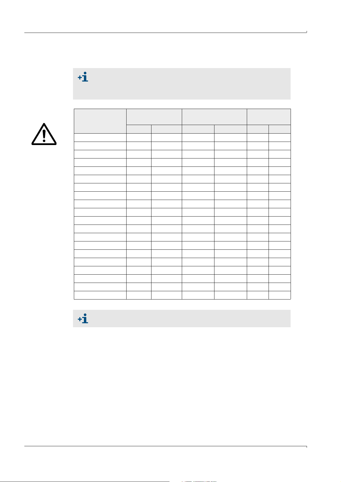
7.1.3 Technical data
TYPE APPROVAL
Type approval
The information in this section may differ from the type approval which is valid
for the FLOWSIC600 in your country.
Please use your national type approval for the FLOWSIC600.
Table 5 Common meter sizes and flow rates
Actual flow rate
Nominal Size
Min. Max. Min. Max. [m/sec] [ft/sec]
DN 50 (NPS 2) 6 400 210 14,000 65 213
DN 80 (NPS 3) 12 1,000 280 35,000 65 213
DN 100 (NPS 4) 20 1,600 460 57,000 60 197
DN 150 (NPS 6) 32 3,000 1,130 106,000 50 164
DN 200 (NPS 8) 40 4,500 1,410 159,000 45 148
DN 250 (NPS 10) 50 7,000 1,770 247,000 40 131
DN 300 (NPS 12) 65 8,000 2,300 283,000 33 108
DN 350 (NPS 14) 80 10,000 2,830 353,000 33 108
DN 400 (NPS 16) 120 14,000 4,240 494,000 33 108
DN 450 (NPS 18) 130 17,000 4,590 600,000 33 108
DN 500 (NPS 20) 200 20,000 7,060 706,000 33 108
DN 600 (NPS 24) 320 32,000 11,300 1,130,000 33 108
DN 700 (NPS 28) 650 40,000 22,950 1,413,000 30 98
DN 750 (NPS 30) 650 45,000 22,950 1,589,000 30 98
DN 800 (NPS 32) 800 50,000 28,250 1,766,000 30 98
DN 900 (NPS 36) 1,000 66,000 35,320 2,331,000 30 98
DN 1000 (NPS 40) 1,200 80,000 42,380 2,825,000 30 98
DN 1050 (NPS 42) 1,300 85,000 45,910 3,002,000 30 98
DN 1100 (NPS 44) 1,400 90,000 49,440 3,178,000 28 92
DN 1200 (NPS 48) 1,600 100,000 56,500 3,531,000 27 89
[m³/h]
Actual flow rate
[ft³/h]
Appendix
Max. Velocity*
82 FLOWSIC600 · Operating Instructions · 8010458 V2.0 · © SICK MAIHAK GmbH
*When a configuration with flow conditioner is used, the velocity of gas must
not exceed 40 m/s (131 ft/s) in the pipe.
Page 83

Appendix
Tab le 6 Technical Data
Material
Meter body Carbon steel 1.1120/ ASME A216 WCC
Stainless steel 1.4408/ ASME A351 Gr. CF 8M
Low temperature carbon steel 1.6220/ASME A352 L CC
Duplex steel 1.4470/ASME A995 Gr.4A/UNS J92205
Common data
Number of measuring paths 1, 2 or 4
Min. gas velocity 0.3 m/s; 1 ft/s
Turn down (v
) Max. 1 : 130
min/vmax
Measured medium
Gases Natural gas, process gases, air, Ethylene, etc.
Pressure range
1
0 bar(g) ... 250 bar(g) (0 psi(g) ... 3600 psi(g)); up to 450 bar(g) (6500 psi(g)) on request
Temperature range -40 °C ... + 180 °C (-40 °F ... 356 °F); -194 °C ... 280 °C (-317 °F ... 536 °F) on request
Measuring uncertainty
Repeatability < 0.1 % of reading
Typical uncertainty 1 path
2 paths
4 paths
± 2.0 %
± 1.0 %
± 0.5 %3 (dry calibrated); ± 0.2 %3 (after flow calibration + adjustment with
constant factor); ± 0.1%
2
2
3
(after flow calibration + adjustment with polynomial
correction)
Power supply
Operating voltage 12 ... 28.8 V DC (minimum 15 V DC for active current output)
Typ. power consumption < 1 W
Outputs
Measured variables Flow rate and volume at flowing and base conditions, gas velocity, speed of sound
Analog output 4 .. 20 mA; active / passive; electrically isolated; max load = 250 Ω
Pulse and status outputs Passive, electrically isolated, open collector or acc. NAMUR, f
= 6 kHz (scalable),
max
pulse width = 0,05 .. 1 s in accordance with NAMUR (EN50227)
Interfaces
MODBUS ASCII and RTU 2 x RS485 for configuration, measured value output and diagnosis
HART® Configuration, measured value output and diagnosis
Ex approval
Europe (ATEX 94/9/EG) II 1/2G Ex de ib [ia] IIA T4 or II 1/2G Ex de ib [ia] IIC T4
Ultrasonic transducers intrinsically safe “ia“
4
USA / Canada (CSA) Class I, Division 1, Group D T4; Class I, Division 2, Group D T4
Class I, Division 1, Groups B,C, D T4; Class I, Division 2, Groups A, B, C, D T4
Ultrasonic transducers intrinsically safe
Ambient conditions
Temperature range -40 °C ... +60 °C (-40 °F .. 140 °F)
Storage temperature -40 °C ... +60 °C (-40 °F .. 140 °F)
IP classification IP 67
Relative humidity < 95 %
1
Depending on transducer type and meter size, a minimum operating pressure can be neccessary. Please consult the manufacturer
2
Within Qt to Q
3
Within Qt to Q
4
Approval for operation of the ultrasonic transducers within zone 0 only valid under atmospheric
conditions (-20 °C ≤ T
and with straight inlet/outlet section of 20D/3D or with flow straightener 10D/3D.
max
and with straight inlet/outlet section of 10 D/3 D or 5 D/3 D with flow straightener
max
≤ +60 °C; 0.8 bar(a) ≤ p
medium
≤ 1.1 bar(a))(-4 °F ≤ T
medium
≤ 140°F; 11.6 psi(a) ≤ p
medium
medium
≤ 16 psi(a))
FLOWSIC600 · Operating Instructions · 8010458 V 2.0 · © SICK MAIHAK GmbH 83
Page 84

Criteria applicable to meter when used in accordance with German PTB specifications
Table 7 Meter sizes according to PTB approval
Appendix
Meter
size
DN 80
(3“)
DN 100
(4“)
DN 150
(6“)
DN 200
(8“)
DN 250
(10“)
DN 300
(12“)
DN 350
(14“)
DN 400
(16“)
DN 450
(18“)
G-class
Measuring range (Qmin [m³/h])
1:100 1:80 1:50 1:30 1:20
Max. flow
rate
Qmax
[m³/h]
Meter
factor
[pulses/
m³]
G160 13 250 28800
G250 13 20 400 18000
G400* 13 20 32 650 11100
G250 20 400 18000
G400 20 32 650 11100
G650* 20 32 50 1000 7200
G400 32 650 11100
G650 32 50 1000 7200
G1000 32 50 80 1600 4500
G1600* 32 50 80 130 2500 2880
G650 50 1000 7200
G1000 50 80 1600 4500
G1600 50 80 130 2500 2880
G2500* 40 80 130 200 4000 1800
G1000 50 80 1600 4500
G1600 50 80 130 2500 2880
G2500 50 80 130 200 4000 1800
G4000* 65 80 130 200 320 6500 1110
G1600 80 130 2500 2880
G2500 80 130 200 4000 1800
G4000 65 80 130 200 320 6500 1110
G4000 E 7800 920
G1600 80 2500 2880
G2500 80 130 200 4000 1800
G4000 80 130 200 320 6500 1110
G4000 E 80 7800 920
G2500 130 200 4000 1800
G4000 130 200 320 6500 1110
G6500 120 200 320 500 10000 720
G6500 E 120 12000 600
G2500 130 4000 1800
G4000 130 200 320 6500 1110
G6500 130 200 320 500 10000 720
G6500 E 120 12000 600
84 FLOWSIC600 · Operating Instructions · 8010458 V2.0 · © SICK MAIHAK GmbH
Page 85

Appendix
Meter
size
DN 500
(20“)
DN 600
(24“)
DN 700
(28“)
DN 800
(32“)
DN 900
(36“)
DN 1000
(40“)
G-class
Measuring range (Qmin [m³/h])
1:100 1:80 1:50 1:30 1:20
Max. flow
rate
Qmax
[m³/h]
Meter
factor
[pulses/
m³]
G4000 200 320 6500 1110
G6500 200 320 500 10000 720
G10000 200 320 500 800 16000 450
G10000 E 200 20000 360
G6500 320 500 10000 720
G10000 320 500 800 16000 450
G16000 320 500 800 1300 25000 288
G16000 E 320 32000 225
G6500 500 10000 720
G10000 500 16000 450
G16000 500 25000 290
G25000 400 500 40000 180
G10000 500 16000 450
G16000 500 25000 290
G25000 500 40000 180
G25000 E 500 48000 150
G10000 800 16000 450
G16000 800 25000 290
G25000 800 40000 180
G40000 650 800 65000 111
G16000 1300 25000 290
G25000 1300 40000 180
G40000 800 1300 65000 111
● Any flow rates given above are also valid in the bidirectional mode.
● G-classes marked with an asterisk (*) must only be used in configuration No. 2 (see
→
pg.27, 3.2.2).
● G-classes marked with an (E) have an extended max. flow rate (max. flow velocity v
max
=
36 m/s) related to commonly established turbine meter G-classes
● The transition flow Q
is based on the flow range the meter is designed for according to
t
the main plate. It is:
- for a flow range of 1:20 Qt=0.20 Q
- for a flow range of 1:30 Qt=0.15 Q
- for a flow range of
FLOWSIC600 · Operating Instructions · 8010458 V 2.0 · © SICK MAIHAK GmbH 85
1:50 Qt=0.10 Q
≥
max
max
max
and
and
.
Page 86

Appendix
7.2
Logbooks
1 Classification of logbook entries
The entries are distinguished into three classes and identified by the initial character in the
first line.
● “I”information
● “W”warning
● “E”error/ malfunction
2 Type of occurrence
● “+”point of time identifying the beginning of a status
● “-”point of time identifying the end of a status
7.2.1 Overview of event entries in logbooks and MEPAFLOW600 CBM
Message No.
on LCD
3002 NO DSP communication 1 E+System 0001
3003 Measurement invalid 1 E+DSP 0001
3004 Firmware CRC invalid 1 E+Firmware 0001
3005 Parameter CRC invalid 1 E+Parameter 0001
3006 Parameter out of range 1 E+Parameter 0001
3007 Failure during storage of path compensation
3008 Meter clock time invalid 1 E+System 0001
Logbook message in MEPAFLOW600 CBM Logbook LCD-Text
Custody logbook [1]
NO DSP-Communic.
E-System 0001
NO DSP-Communic.
Reading invalid
E-DSP 0001
Reading invalid
CRC invalid
E-Firmware 0001
CRC invalid
CRC invalid
E-Parameter 0001
CRC invalid
#XXXX range error
E-Parameter 0001
#XXXX range error
1 E+PathComp. 0001
parameter
Storage error
E-PathComp. 0001
Storage error
ClockTime inval.
E-System 0001
ClockTime inval.
86 FLOWSIC600 · Operating Instructions · 8010458 V2.0 · © SICK MAIHAK GmbH
Page 87

Appendix
Message No.
on LCD
3009 Custody logbook [1] overflow 1 E+Logbook 1 0001
3011 CRC volume counter (a.c) invalid 1 E+Count.ac 0001
3012 CRC volume counter (n.c) invalid 1 E+Count.sc 0001
3013 Transit time mode activated 1 E+System 0001
3014 No signature key 1 E+System 0001
2001 Path failure 1 W+PathError 0001
2002 No HART communication to temperature
2003 No HART communication to pressure transmitter 1 W+HART P 0001
2004 Maximum pulse output frequency exceeded
2005 EVC parameter invalid 1 W+EVC 0001
2006 EVC hardware error 1 W+EVC 0001
1001 Flow meter power ON 1 I Power ON 0001
1002 Meter clock adjusted 1 I Set Time 0001
Logbook message in MEPAFLOW600 CBM Logbook LCD-Text
Overflow
E-Logbook 1 0001
Overflow
CRC invalid
E-Count.ac 0001
CRC invalid
CRC invalid
E-Count.sc 0001
CRC invalid
TransitTimeMode
E-System 0001
TransitTimeMode
No signature key
E-System 0001
No signature key
Path 1 2 3 4
W-PathError 0001
All paths OK
1 W+HART T 0001
transmitter
1 W+PulseOut 0001
(6kHz)
No communication
W-HART T 0001
No communication
No communication
W-HART P 0001
No communication
6000 Hz exceeded
W-PulseOut 0001
6000 Hz exceeded
EVC para.invalid
W-EVC 0001
EVC para.invalid
EVC module error
W-EVC 0001
EVC module error
dd/mm/yy mm:ss
dd/mm/yy mm:ss
FLOWSIC600 · Operating Instructions · 8010458 V 2.0 · © SICK MAIHAK GmbH 87
Page 88

Appendix
Message No.
on LCD
1003 Configuration Mode active 1 I+Meas.Mode 0001
1004 Firmware changed 1 I Update FW 0001
1007 Custody logbook [1] erased and initialized 1 I Logbook 1 0001
1014 Overflow volume counter (a.c.) 1 I Count.ac 0001
1015 Overflow volume counter (s.c.) 1 I Count.sc 0001
1016 Error volume counter cleared 1 I Reset E 0001
1017 All volume counters cleared 1 I Reset V 0001
1027
1029 Air test mode activated 1 I+Airtest 0001
1008 Warning logbook [2] erased and initialized 2 I Logbook 2 0001
1010 Warning logbook [2] overflow 2 I+Logbook 2 0001
1018 DataLog 1 cleared 2 I DataLog 1 0001
1019 DataLog 2 cleared 2 I DataLog 2 0001
1020 DataLog 3 cleared 2 I DataLog 3 0001
1021 DataLog 1 overflow 2 I+DataLog 1 0001
1022 DataLog 2 overflow 2 I+DataLog 2 0001
Logbook message in MEPAFLOW600 CBM Logbook LCD-Text
Configurat. ON 1
I-Meas.Mode 0001
Measurement ON 1
3104 -> 3200
Reset and Init
Overflow
Overflow
01/01/07 10:47
01/01/07 10:47
Initialization error
→ Default parameter loaded
Warning logbook [2]
1 I+InitError 0001
DefaultParaLoad
I-InitError 0001
DefaultParaLoad
Active
I-Airtest 0001
Not active
Reset and Init
Overflow
I-Logbook 2 0001
Overflow
Reset
Reset
Reset
Overflow
I-DataLog 1 0001
Overflow
Overflow
I-DataLog 2 0001
Overflow
88 FLOWSIC600 · Operating Instructions · 8010458 V2.0 · © SICK MAIHAK GmbH
Page 89

Appendix
Message No.
on LCD
1023 DataLog 3 overflow 2 I+DataLog 3 0001
1024 DatenLog 1 CRC error 2 I+DataLog 1 0001
1025 DatenLog 2 CRC error 2 I+DataLog 2 0001
1026 DataLog 3 CRC error 2 I+DataLog 3 0001
1028 Customer limit exceeded 2 I+Userlimit 0001
1005 Parameter changed 3 I Parameter 0001
1006 All parameters to default (Reset) 3 I Parameter 0001
1009 Parameter logbook [3] erased and initialized 3 I Logbook 3 0001
1011 Parameter logbook [3] overflow 3 I+Logbook 3 0001
Logbook message in MEPAFLOW600 CBM Logbook LCD-Text
Overflow
I-DataLog 3 0001
Overflow
CRC invalid
I-DataLog 1 0001
CRC invalid
CRC invalid
I-DataLog 2 0001
CRC invalid
CRC invalid
I-DataLog 3 0001
CRC invalid
Limit XXXXXXXXXX
I-Userlimit 0001
Limits OK
Parameter logbook [3]
Change Reg3001
Reset all
Reset and Init
Overflow
I-Logbook 3 0001
Overflow
FLOWSIC600 · Operating Instructions · 8010458 V 2.0 · © SICK MAIHAK GmbH 89
Page 90

Appendix
7.3
Connection Diagrams for Operating the FLOWSIC 600 in Hazardous Areas in Accordance with North American Guidelines (CSA)
Figure 39 Control drawing CSA 781.00.02 (page 1)
90 FLOWSIC600 · Operating Instructions · 8010458 V2.0 · © SICK MAIHAK GmbH
Page 91

Appendix
Figure 40 Control drawing CSA 781.00.02 (page 2)
FLOWSIC600 · Operating Instructions · 8010458 V 2.0 · © SICK MAIHAK GmbH 91
Page 92

Appendix
internal
Non Hazard Area
.
<= 24V DC
<= 24V DC
R
L
R
L
<= 24V DC
<= 24V DC
R
L
R
L
24V DC +
24V Gnd
shield
RS 485
Ex
[EEx ib] IIC
RS 232
24VDC
STAHL 9185
RxD T xD
Service
Interface
Modbus
Volume pulse
Status
Status
Explosion Hazard Location
Intrinsic savety circuits
Non Intrinsic savety circuits
AO 0
DO 0
FLOWSIC 600
RS 485
DO 1
DO 2
DO 3
Class1, Division1, Groups B, C and D
Class1, Division2, Groups A, B, C and D
Class1, Zone 1 Group IIB + Hydrogene
Class1, Zone 2, Group IIC
II 1/2G EEx de ib [ia] IIC T4 or
II 1/2G EEx de ib [ia] IIA T4
31+
32-
33+
34-
51+
52-
41+
42-
81+
82-
1 (+)
2 (-)
FL600
Li2YCYv(TP)
4x2x0,5 mm²
ScreenScreen
(TP) - Twisted pair
NYY-O
2 x 1,5 mm²
Li2YCYv(TP)
2x0,5 mm²
in EU in accordance with EN 60079-14
National regulation must be observed.
maximum length: 100 m
RS485 Modbus - approx. impedance 120 Ohm
1/2" NPT (North America)
6 - 12 mm cable diameter
Attention:
!
WARNING!
Incorrect cabling can cause
the FLOWSIC 600 to fail!
For further details see
operation manual.
Cable glands
Intrinsic savety installation:
in accordance with
in North America
NEC and CEC, see
Control Drawing 781.00.02
Compliance CSA 1298901
EC-Typ-Examination Certificate
For Savety/Entity - Parameters see
TÜV 01 ATEX 1766 X resp. Certificate of
M20 x 1,5 (EU) or
or 4 .. 20 mA passiv
Volume pulse
Remark:
Flowcomputer
SICK recommends to connect all signals
of FLOWSIC 600 with cabels to the non
hazardous area.
Ex
24VDC
[EEx ia] IIC
1+
4-
2+
5-
8+
9-
11
12
10-
7+
MK13-22EX0-T/24VDC
Ex
24VDC
[EEx ia] IIC
1+
4-
2+
5-
8+
9-
11
12
10-
7+
MK13-22EX0-T/24VDC
[EEx ib]
L N
Ex
9143
STAHL
10
11
STHAL power supply
9143/10-156-160-10s
7.4
Wiring Examples
7.4.1 Intrinsically safe installation
Figure 41 FLOWSIC600 intrinsically safe installation
92 FLOWSIC600 · Operating Instructions · 8010458 V2.0 · © SICK MAIHAK GmbH
Page 93

Appendix
.
-X
.
. .
L
R
Imax = 100 mA
super fast
100 mA
fast
1A
internal
Fuse
Fuse
24 V DC
Non Hazard Area
Volume pulse
Hazard LocationExplosion
or 4 .. 20 mA
Status
..
Fuse
Imax = 100 mA
R
L
..
Fuse
Imax = 100 mA
R
L
. .
Fuse
Imax = 100 mA
R
L
Modbus
Status
<= 24V DC
<= 24V DC
<= 24V DC
<= 24V DC
super fast
100 mA
super fast
100 mA
L N
24 VDC
.
AO 0
DO 0
FLOWSIC 600
RS 485
DO 1
DO 2
DO 3
Class1, Division1, Groups B, C and D
Class1, Division2, Groups A, B, C and D
Class1, Zone 1 Group IIB + Hydrogene
Class1, Zone 2, Group IIC
II 1/2G EEx de ib [ia] IIC T4 or
II 1/2G EEx de ib [ia] IIA T4
31+
32-
33+
34-
51+
52-
41+
42-
81+
82-
1 (+)
2 (-)
FL600
NYY-O
2 x 1,5 mm²
. .
100 mA
super fast
Li2YCYv(TP)
2x0,5 mm²
Li2YCYv(TP)
4x2x0,5 mm²
(TP) - Twisted pair
Fuse
Screen
Attention:
6 - 12 mm cable diameter
1/2" NPT (North America)
RS485 Modbus - approx. impedance 120 Ohm
maximum length: 100 m
Cable glands
operation manual.
For further details see
the FLOWSIC 600 to fail!
Incorrect cabling can cause
WARNING!
!
in EU in accordance with EN 60079-14
National regulation must be observed.
Volume pulse
in North America
Non intrinsic installation:
see control drawing 781.00.02
in accordance with NEC and CEC,
M20 x 1,5 (EU) or
Flowcomputer/Systemcontroller
Fuses for field terminals:
Very fast acting type (FF-Type)
In case of blow out lock for reason
before change.
Additional surge protection is
recommended in case of powerful or
recurrent strokes of lightning.
Remark:
SICK recommends to connect all signals
of FLOWSIC 600 with cabels to the non
hazardous area.
7.4.2
Non-intrinsically safe installation
Figure 42 FLOWSIC600 non-intrinsically safe installation
FLOWSIC600 · Operating Instructions · 8010458 V 2.0 · © SICK MAIHAK GmbH 93
Page 94

Appendix
7.5
Figure 43 Sealing plan, part 1
Sealing Plan
94 FLOWSIC600 · Operating Instructions · 8010458 V2.0 · © SICK MAIHAK GmbH
Page 95

Appendix
Figure 44 Sealing plan, part 2
FLOWSIC600 · Operating Instructions · 8010458 V 2.0 · © SICK MAIHAK GmbH 95
Page 96

Figure 45 Sealing plan, part 3
Appendix
96 FLOWSIC600 · Operating Instructions · 8010458 V2.0 · © SICK MAIHAK GmbH
Page 97

Appendix
alternatively
Figure 46 Sealing plan, part 4
FLOWSIC600 · Operating Instructions · 8010458 V 2.0 · © SICK MAIHAK GmbH 97
Page 98

Figure 47 Examples: Main type plates at the signal processing unit
Appendix
Figure 48 Example: Type plate at the meter body
98 FLOWSIC600 · Operating Instructions · 8010458 V2.0 · © SICK MAIHAK GmbH
Page 99

Appendix
FLOWSIC600 · Operating Instructions · 8010458 V 2.0 · © SICK MAIHAK GmbH 99
Page 100

FLOWSIC600
SICK worldwide
You will find our local subsidiary
or agency at:
www.sick.com
8010458/2010-01 (V2.0)
Your local sales and service partner
SICK MAIHAK GmbH | Germany
Nimburger Str. 11 | 79276 Reute | www.sick.com
Phone +49 7641 469-0 | Fax +49 7641 469-11 49 | info.pa@sick.de
 Loading...