

Page 1
Title Page
FLOWSIC500
Ultrasonic Gas Flow Meter with
Optional Volume Conversion
Installation
Operation
Maintenance
OPERATING INSTRUCTIONS
Page 2

Document Information
Glossary
Described Product
Product name: FLOWSIC500
Document ID
Title: Operating Instructions FLOWSIC500
Part No.: 8015391
Document ID: 9186957
Version: 2-3
Release: 2016-10
Manufacturer
SICK Engineering GmbH
Bergener Ring 27 · D-01458 Ottendorf-Okrilla · Germany
Phone: +49 35205 52410
Fax: +49 35205 52450
E-Mail: info.pa@sick.de
Original Documents
The English version 8015391 of this document is an original document from SICK Engineering GmbH.
SICK Engineering GmbH assumes no liability for the correctness of
an unauthorized translation.
Please contact SICK Engineering GmbH or your local representative in case of doubt.
Legal Information
Subject to change without notice.
© SICK Engineering GmbH. All rights reserved.
AC Alternating Current
Al Aluminium
ATEX ATEX: Atmosphères Explosifs: Abbreviation for Euro-
pean standards that govern safety in potentially
explosive atmospheres
CSA Canadian Standards Association (www.csa.ca)
DC Direct Current
HF High frequency, e. g. HF pulses
IEC International Electronical Commission
IECEx IEC system for certification in accordance with stan-
dards for devices for use in potentially explosive
atmospheres
IPxy Ingress Protection: Degree of protection of a device
in accordance with IEC/DIN EN 60529; x specifies
the protection against contact and impurities, y protection against moisture.
LF Low frequency, e. g. LF pulses
MDR Manufacturer Data Record
NAMUR Abbreviation for "Normen-Arbeitsgemeinschaft für
Mess- und Regeltechnik in der chemischen Industrie", now "Interessengemeinschaft Automatisierungstechnik der Prozessindustrie" (www.namur.de)
pTZ Volume conversion as a function of the pressure,
the temperature and with consideration of the compression factor
TZ Volume conversion as function of the temperature
and a fixed pressure value and with consideration
of the compression factor
2 FLOWSIC500 · Operating Instructions · 8015391/Z261/V2-3/2016-10 · © SICK Engineering GmbH
Page 3
Warning Symbols
Information Symbols
IMMEDIATE HAZARD
of severe injuries or death
Hazard (general)
Hazard by electrical voltage
Hazard in potentially explosive atmospheres
Hazard by explosive substances/mixtures
Hazard by unhealthy substances
Hazard by toxic substances
Warning Levels / Signal Words
Information on product condition with regard to protection against explosions (general)
Information on product characteristics related to European Directive ATEX
Information on product characteristics related to explosion protection in accordance with the IECEx scheme.
Important technical information for this product
Important information on electric or electronic functions
Nice to know
Supplementary information
Link referring to information at another place
DANGER
Risk or hazardous situation which will result in severe personal
injury or death.
WARNING
Risk or hazardous situation which could result in severe personal
injury or death.
CAUTION
Hazard or unsafe practice which could result in personal injury or
property damage.
NOTICE
Hazards which could result in property damage
FLOWSIC500 · Operating Instructions · 8015391/Z261/V 2-3/2016-10 · © SICK Engineering GmbH 3
Page 4

Contents
Contents
1 Important Information . . . . . . . . . . . . . . . . . . . . . . . . . . . . . . . . . . . . . . . . . . . . . . . 9
1.1 Main hazards . . . . . . . . . . . . . . . . . . . . . . . . . . . . . . . . . . . . . . . . . . . . . . . . . . . . . . . . . . . . . . 10
1.2 About this document . . . . . . . . . . . . . . . . . . . . . . . . . . . . . . . . . . . . . . . . . . . . . . . . . . . . . . . . 10
1.3 Intended use . . . . . . . . . . . . . . . . . . . . . . . . . . . . . . . . . . . . . . . . . . . . . . . . . . . . . . . . . . . . . . . 11
1.3.1 Purpose of the device . . . . . . . . . . . . . . . . . . . . . . . . . . . . . . . . . . . . . . . . . . . . . . . . . . . . . 11
1.3.2 Product identification . . . . . . . . . . . . . . . . . . . . . . . . . . . . . . . . . . . . . . . . . . . . . . . . . . . . 11
1.3.3 Operation in potentially explosive atmospheres . . . . . . . . . . . . . . . . . . . . . . . . . . . . . 12
1.3.4 Combustible gas . . . . . . . . . . . . . . . . . . . . . . . . . . . . . . . . . . . . . . . . . . . . . . . . . . . . . . . . . 12
1.3.5 Restrictions of use . . . . . . . . . . . . . . . . . . . . . . . . . . . . . . . . . . . . . . . . . . . . . . . . . . . . . . . 12
1.3.6 Cleaning . . . . . . . . . . . . . . . . . . . . . . . . . . . . . . . . . . . . . . . . . . . . . . . . . . . . . . . . . . . . . . . . . 13
1.4 Responsibility of user . . . . . . . . . . . . . . . . . . . . . . . . . . . . . . . . . . . . . . . . . . . . . . . . . . . . . . . 13
1.5 Additional documentation/information . . . . . . . . . . . . . . . . . . . . . . . . . . . . . . . . . . . . . . . . 14
2 Product Description . . . . . . . . . . . . . . . . . . . . . . . . . . . . . . . . . . . . . . . . . . . . . . . . . 15
2.1 Operating principle . . . . . . . . . . . . . . . . . . . . . . . . . . . . . . . . . . . . . . . . . . . . . . . . . . . . . . . . . 16
2.1.1 Gas flow meter . . . . . . . . . . . . . . . . . . . . . . . . . . . . . . . . . . . . . . . . . . . . . . . . . . . . . . . . . . . 16
2.1.2 Volume conversion (optional) . . . . . . . . . . . . . . . . . . . . . . . . . . . . . . . . . . . . . . . . . . . . . . 16
2.2 FLOWSIC500 measuring system . . . . . . . . . . . . . . . . . . . . . . . . . . . . . . . . . . . . . . . . . . . . . 17
2.2.1 Adapter . . . . . . . . . . . . . . . . . . . . . . . . . . . . . . . . . . . . . . . . . . . . . . . . . . . . . . . . . . . . . . . . . 17
2.2.2 Gas flow meter . . . . . . . . . . . . . . . . . . . . . . . . . . . . . . . . . . . . . . . . . . . . . . . . . . . . . . . . . . . 18
2.3 Meter sizes . . . . . . . . . . . . . . . . . . . . . . . . . . . . . . . . . . . . . . . . . . . . . . . . . . . . . . . . . . . . . . . . 18
2.4 Power supply . . . . . . . . . . . . . . . . . . . . . . . . . . . . . . . . . . . . . . . . . . . . . . . . . . . . . . . . . . . . . . . 18
2.5 Interfaces . . . . . . . . . . . . . . . . . . . . . . . . . . . . . . . . . . . . . . . . . . . . . . . . . . . . . . . . . . . . . . . . . . 18
2.5.1 Pulse and status outputs . . . . . . . . . . . . . . . . . . . . . . . . . . . . . . . . . . . . . . . . . . . . . . . . . . 19
2.5.2 Encoder totalizer . . . . . . . . . . . . . . . . . . . . . . . . . . . . . . . . . . . . . . . . . . . . . . . . . . . . . . . . . 19
2.5.3 Serial data interface . . . . . . . . . . . . . . . . . . . . . . . . . . . . . . . . . . . . . . . . . . . . . . . . . . . . . . 19
2.5.4 Optical data interface . . . . . . . . . . . . . . . . . . . . . . . . . . . . . . . . . . . . . . . . . . . . . . . . . . . . . 19
2.6 Device option: Volume conversion . . . . . . . . . . . . . . . . . . . . . . . . . . . . . . . . . . . . . . . . . . . . 20
2.6.1 Volume conversion . . . . . . . . . . . . . . . . . . . . . . . . . . . . . . . . . . . . . . . . . . . . . . . . . . . . . . . 20
2.6.2 Integrated pressure and temperature transmitters . . . . . . . . . . . . . . . . . . . . . . . . . . 21
2.6.3 External pressure and temperature transmitters . . . . . . . . . . . . . . . . . . . . . . . . . . . . 21
2.7 Totalizers . . . . . . . . . . . . . . . . . . . . . . . . . . . . . . . . . . . . . . . . . . . . . . . . . . . . . . . . . . . . . . . . . . 22
2.7.1 Device status and totalizers used . . . . . . . . . . . . . . . . . . . . . . . . . . . . . . . . . . . . . . . . . . 22
2.7.2 Reverse flow . . . . . . . . . . . . . . . . . . . . . . . . . . . . . . . . . . . . . . . . . . . . . . . . . . . . . . . . . . . . . 23
2.8 Logbooks and Archives . . . . . . . . . . . . . . . . . . . . . . . . . . . . . . . . . . . . . . . . . . . . . . . . . . . . . . 23
2.9 Parameter protection . . . . . . . . . . . . . . . . . . . . . . . . . . . . . . . . . . . . . . . . . . . . . . . . . . . . . . . 24
2.9.1 Parameter locking switch . . . . . . . . . . . . . . . . . . . . . . . . . . . . . . . . . . . . . . . . . . . . . . . . . 24
2.9.2 Metrology logbook . . . . . . . . . . . . . . . . . . . . . . . . . . . . . . . . . . . . . . . . . . . . . . . . . . . . . . . . 24
2.10 Sealing . . . . . . . . . . . . . . . . . . . . . . . . . . . . . . . . . . . . . . . . . . . . . . . . . . . . . . . . . . . . . . . . . . . . 26
3 Installation . . . . . . . . . . . . . . . . . . . . . . . . . . . . . . . . . . . . . . . . . . . . . . . . . . . . . . . . . . . . 29
3.1 Hazards during installation . . . . . . . . . . . . . . . . . . . . . . . . . . . . . . . . . . . . . . . . . . . . . . . . . 30
3.2 General information . . . . . . . . . . . . . . . . . . . . . . . . . . . . . . . . . . . . . . . . . . . . . . . . . . . . . . . . . 30
3.2.1 Delivery . . . . . . . . . . . . . . . . . . . . . . . . . . . . . . . . . . . . . . . . . . . . . . . . . . . . . . . . . . . . . . . . . 30
3.2.2 Transport . . . . . . . . . . . . . . . . . . . . . . . . . . . . . . . . . . . . . . . . . . . . . . . . . . . . . . . . . . . . . . . . 31
3.3 Mechanical installation . . . . . . . . . . . . . . . . . . . . . . . . . . . . . . . . . . . . . . . . . . . . . . . . . . . . . . 31
3.3.1 Preparations . . . . . . . . . . . . . . . . . . . . . . . . . . . . . . . . . . . . . . . . . . . . . . . . . . . . . . . . . . . . . 31
3.3.2 Choosing flanges, gaskets and other components . . . . . . . . . . . . . . . . . . . . . . . . . . . 32
3.3.3 Fitting the FLOWSIC500 in the pipeline . . . . . . . . . . . . . . . . . . . . . . . . . . . . . . . . . . . . . 34
4 FLOWSIC500 · Operating Instructions · 8015391/Z261/V2-3/2016-10 · © SICK Engineering GmbH
Page 5

Contents
3.4 Electrical installation . . . . . . . . . . . . . . . . . . . . . . . . . . . . . . . . . . . . . . . . . . . . . . . . . . . . . . . . 37
3.4.1 Requirements for use in potentially explosive atmospheres . . . . . . . . . . . . . . . . . . . 37
3.4.2 Criteria for electrical connection . . . . . . . . . . . . . . . . . . . . . . . . . . . . . . . . . . . . . . . . . . . 39
3.4.3 Opening and closing the electronics cover . . . . . . . . . . . . . . . . . . . . . . . . . . . . . . . . . . 39
3.4.4 Rotating the control unit . . . . . . . . . . . . . . . . . . . . . . . . . . . . . . . . . . . . . . . . . . . . . . . . . . . 40
3.4.5 Electrical connections . . . . . . . . . . . . . . . . . . . . . . . . . . . . . . . . . . . . . . . . . . . . . . . . . . . . . 41
3.4.6 Pin assignment of plug-in connectors . . . . . . . . . . . . . . . . . . . . . . . . . . . . . . . . . . . . . . . 42
3.4.7 Cable specifications . . . . . . . . . . . . . . . . . . . . . . . . . . . . . . . . . . . . . . . . . . . . . . . . . . . . . . 43
3.4.8 Operation with external power supply . . . . . . . . . . . . . . . . . . . . . . . . . . . . . . . . . . . . . . . 44
3.4.9 Operation with batteries . . . . . . . . . . . . . . . . . . . . . . . . . . . . . . . . . . . . . . . . . . . . . . . . . . . 45
3.5 Installing the external pressure and temperature transmitters . . . . . . . . . . . . . . . . . . . 46
3.5.1 Fitting the plug-in connector cover . . . . . . . . . . . . . . . . . . . . . . . . . . . . . . . . . . . . . . . . . 46
3.5.2 Installing the pressure transmitter . . . . . . . . . . . . . . . . . . . . . . . . . . . . . . . . . . . . . . . . . 48
3.5.3 Installing the temperature transmitter . . . . . . . . . . . . . . . . . . . . . . . . . . . . . . . . . . . . . . 52
4Start-up . . . . . . . . . . . . . . . . . . . . . . . . . . . . . . . . . . . . . . . . . . . . . . . . . . . . . . . . . . . . . . . . . 53
4.1 Sequence of start-up . . . . . . . . . . . . . . . . . . . . . . . . . . . . . . . . . . . . . . . . . . . . . . . . . . . . . . . . 54
4.1.1 Start-up of gas flow meter . . . . . . . . . . . . . . . . . . . . . . . . . . . . . . . . . . . . . . . . . . . . . . . . .54
4.1.2 Start-up of gas flow meter with device option volume conversion . . . . . . . . . . . . . .54
4.2 Setting the date and time . . . . . . . . . . . . . . . . . . . . . . . . . . . . . . . . . . . . . . . . . . . . . . . . . . . . 54
4.3 Configuring volume conversion (device option) . . . . . . . . . . . . . . . . . . . . . . . . . . . . . . . . . 55
4.3.1 Setting fixed values . . . . . . . . . . . . . . . . . . . . . . . . . . . . . . . . . . . . . . . . . . . . . . . . . . . . . . . 55
4.3.2 Checking the configuration . . . . . . . . . . . . . . . . . . . . . . . . . . . . . . . . . . . . . . . . . . . . . . . . 55
4.3.3 Configuring the gas composition . . . . . . . . . . . . . . . . . . . . . . . . . . . . . . . . . . . . . . . . . . . 56
4.4 Checking the device status . . . . . . . . . . . . . . . . . . . . . . . . . . . . . . . . . . . . . . . . . . . . . . . . . . 56
5Operation . . . . . . . . . . . . . . . . . . . . . . . . . . . . . . . . . . . . . . . . . . . . . . . . . . . . . . . . . . . . . . 57
5.1 Control unit . . . . . . . . . . . . . . . . . . . . . . . . . . . . . . . . . . . . . . . . . . . . . . . . . . . . . . . . . . . . . . . . . 58
5.2 Operating using the display . . . . . . . . . . . . . . . . . . . . . . . . . . . . . . . . . . . . . . . . . . . . . . . . . . 58
5.2.1 Display in the symbol bar . . . . . . . . . . . . . . . . . . . . . . . . . . . . . . . . . . . . . . . . . . . . . . . . . .59
5.2.2 Battery fill level display . . . . . . . . . . . . . . . . . . . . . . . . . . . . . . . . . . . . . . . . . . . . . . . . . . . . 59
5.2.3 Main screen (without device option volume conversion) . . . . . . . . . . . . . . . . . . . . . . 60
5.2.4 Main display (with device option volume conversion) . . . . . . . . . . . . . . . . . . . . . . . . . 62
5.2.5 Configuration of main display . . . . . . . . . . . . . . . . . . . . . . . . . . . . . . . . . . . . . . . . . . . . . . 66
5.2.6 FLOWSIC500 menu . . . . . . . . . . . . . . . . . . . . . . . . . . . . . . . . . . . . . . . . . . . . . . . . . . . . . . . 67
5.2.7 Changing the user level . . . . . . . . . . . . . . . . . . . . . . . . . . . . . . . . . . . . . . . . . . . . . . . . . . . 72
5.2.8 Setting the language . . . . . . . . . . . . . . . . . . . . . . . . . . . . . . . . . . . . . . . . . . . . . . . . . . . . . . 72
5.2.9 Changing the device mode . . . . . . . . . . . . . . . . . . . . . . . . . . . . . . . . . . . . . . . . . . . . . . . . 72
5.2.10 Changing parameters . . . . . . . . . . . . . . . . . . . . . . . . . . . . . . . . . . . . . . . . . . . . . . . . . . . . . 73
5.2.11 Resetting the error volume . . . . . . . . . . . . . . . . . . . . . . . . . . . . . . . . . . . . . . . . . . . . . . . . 73
5.2.12 Resetting the event summary . . . . . . . . . . . . . . . . . . . . . . . . . . . . . . . . . . . . . . . . . . . . . .73
5.2.13 Confirming battery replacement . . . . . . . . . . . . . . . . . . . . . . . . . . . . . . . . . . . . . . . . . . . . 74
5.2.14 Checking the external power supply . . . . . . . . . . . . . . . . . . . . . . . . . . . . . . . . . . . . . . . . 74
5.2.15 Testing the display . . . . . . . . . . . . . . . . . . . . . . . . . . . . . . . . . . . . . . . . . . . . . . . . . . . . . . . . 74
5.3 Operating using the optical data interface . . . . . . . . . . . . . . . . . . . . . . . . . . . . . . . . . . . . . 75
5.4 FLOWgate500 operating software . . . . . . . . . . . . . . . . . . . . . . . . . . . . . . . . . . . . . . . . . . . .75
FLOWSIC500 · Operating Instructions · 8015391/Z261/V 2-3/2016-10 · © SICK Engineering GmbH 5
Page 6

Contents
6 Clearing Malfunctions . . . . . . . . . . . . . . . . . . . . . . . . . . . . . . . . . . . . . . . . . . . . . . 77
6.1 Contacting Customer Service . . . . . . . . . . . . . . . . . . . . . . . . . . . . . . . . . . . . . . . . . . . . . . . . 78
6.2 Status messages . . . . . . . . . . . . . . . . . . . . . . . . . . . . . . . . . . . . . . . . . . . . . . . . . . . . . . . . . . . 78
6.3 Additional messages in the Event logbook . . . . . . . . . . . . . . . . . . . . . . . . . . . . . . . . . . . . 80
7 Maintenance and Meter Replacement . . . . . . . . . . . . . . . . . . . . . . . . . 81
7.1 Information on handling lithium batteries . . . . . . . . . . . . . . . . . . . . . . . . . . . . . . . . . . . . . 82
7.1.1 Information on storage and transport . . . . . . . . . . . . . . . . . . . . . . . . . . . . . . . . . . . . . . 83
7.1.2 Disposal information . . . . . . . . . . . . . . . . . . . . . . . . . . . . . . . . . . . . . . . . . . . . . . . . . . . . . 83
7.2 Maintenance when using external power supply . . . . . . . . . . . . . . . . . . . . . . . . . . . . . . . 84
7.2.1 Service life of backup battery . . . . . . . . . . . . . . . . . . . . . . . . . . . . . . . . . . . . . . . . . . . . . . 84
7.2.2 Changing the backup battery . . . . . . . . . . . . . . . . . . . . . . . . . . . . . . . . . . . . . . . . . . . . . . 84
7.3 Maintenance when using battery power supply . . . . . . . . . . . . . . . . . . . . . . . . . . . . . . . . 85
7.3.1 Service life of battery packs . . . . . . . . . . . . . . . . . . . . . . . . . . . . . . . . . . . . . . . . . . . . . . . 85
7.3.2 Changing the battery packs . . . . . . . . . . . . . . . . . . . . . . . . . . . . . . . . . . . . . . . . . . . . . . . 85
7.4 Meter exchange . . . . . . . . . . . . . . . . . . . . . . . . . . . . . . . . . . . . . . . . . . . . . . . . . . . . . . . . . . . . 87
7.4.1 Prerequisites for meter replacement . . . . . . . . . . . . . . . . . . . . . . . . . . . . . . . . . . . . . . . 87
7.4.2 Hazards during meter replacement . . . . . . . . . . . . . . . . . . . . . . . . . . . . . . . . . . . . . . . . 87
7.4.3 Sequence of meter replacement . . . . . . . . . . . . . . . . . . . . . . . . . . . . . . . . . . . . . . . . . . . 87
7.4.4 Required tools and auxiliary material . . . . . . . . . . . . . . . . . . . . . . . . . . . . . . . . . . . . . . . 88
7.4.5 Overview . . . . . . . . . . . . . . . . . . . . . . . . . . . . . . . . . . . . . . . . . . . . . . . . . . . . . . . . . . . . . . . . 89
7.4.6 Back-up of user-specific configuration of installed gas flow meter . . . . . . . . . . . . . 90
7.4.7 Disconnecting electrical connections . . . . . . . . . . . . . . . . . . . . . . . . . . . . . . . . . . . . . . . 90
7.4.8 Removing the installed gas flow meter . . . . . . . . . . . . . . . . . . . . . . . . . . . . . . . . . . . . . 91
7.4.9 Installing the replacement gas flow meter . . . . . . . . . . . . . . . . . . . . . . . . . . . . . . . . . . 95
7.4.10 Performing a leak tightness check . . . . . . . . . . . . . . . . . . . . . . . . . . . . . . . . . . . . . . . . . 97
7.4.11 Checking the function of the gas flow meter . . . . . . . . . . . . . . . . . . . . . . . . . . . . . . . . 99
7.4.12 Securing metrologically . . . . . . . . . . . . . . . . . . . . . . . . . . . . . . . . . . . . . . . . . . . . . . . . . . . 99
7.5 Function check of a pressure or temperature transmitter . . . . . . . . . . . . . . . . . . . . . . 100
7.6 Exchanging an external pressure or temperature transmitter . . . . . . . . . . . . . . . . . . . 100
7.6.1 Exchanging the pressure transmitter . . . . . . . . . . . . . . . . . . . . . . . . . . . . . . . . . . . . . . 100
7.6.2 Exchanging the temperature transmitter . . . . . . . . . . . . . . . . . . . . . . . . . . . . . . . . . . . 101
8 Accessories and Spare Parts . . . . . . . . . . . . . . . . . . . . . . . . . . . . . . . . . . . . . 103
8.1 Accessories . . . . . . . . . . . . . . . . . . . . . . . . . . . . . . . . . . . . . . . . . . . . . . . . . . . . . . . . . . . . . . . 104
8.1.1 Gas flow meter accessories . . . . . . . . . . . . . . . . . . . . . . . . . . . . . . . . . . . . . . . . . . . . . . 104
8.1.2 Volume conversion (device option) accessories . . . . . . . . . . . . . . . . . . . . . . . . . . . . 105
8.1.3 Transport accessories . . . . . . . . . . . . . . . . . . . . . . . . . . . . . . . . . . . . . . . . . . . . . . . . . . . 105
8.2 Spare parts . . . . . . . . . . . . . . . . . . . . . . . . . . . . . . . . . . . . . . . . . . . . . . . . . . . . . . . . . . . . . . . 106
8.2.1 Gas flow meter spare parts . . . . . . . . . . . . . . . . . . . . . . . . . . . . . . . . . . . . . . . . . . . . . . . 106
8.2.2 Volume conversion (device option) spare parts . . . . . . . . . . . . . . . . . . . . . . . . . . . . . 106
6 FLOWSIC500 · Operating Instructions · 8015391/Z261/V2-3/2016-10 · © SICK Engineering GmbH
Page 7

Contents
9 Annex . . . . . . . . . . . . . . . . . . . . . . . . . . . . . . . . . . . . . . . . . . . . . . . . . . . . . . . . . . . . . . . . . .107
9.1 Conformities and Technical Data . . . . . . . . . . . . . . . . . . . . . . . . . . . . . . . . . . . . . . . . . . . .108
9.1.1 CE certificate . . . . . . . . . . . . . . . . . . . . . . . . . . . . . . . . . . . . . . . . . . . . . . . . . . . . . . . . . . . .108
9.1.2 Standards compatibility . . . . . . . . . . . . . . . . . . . . . . . . . . . . . . . . . . . . . . . . . . . . . . . . . . 108
9.1.3 Technical Data . . . . . . . . . . . . . . . . . . . . . . . . . . . . . . . . . . . . . . . . . . . . . . . . . . . . . . . . . .109
9.1.4 Flow rates . . . . . . . . . . . . . . . . . . . . . . . . . . . . . . . . . . . . . . . . . . . . . . . . . . . . . . . . . . . . . . 111
9.1.5 Overload protection . . . . . . . . . . . . . . . . . . . . . . . . . . . . . . . . . . . . . . . . . . . . . . . . . . . . . .111
9.2 Type code . . . . . . . . . . . . . . . . . . . . . . . . . . . . . . . . . . . . . . . . . . . . . . . . . . . . . . . . . . . . . . . . .112
9.3 Type plates . . . . . . . . . . . . . . . . . . . . . . . . . . . . . . . . . . . . . . . . . . . . . . . . . . . . . . . . . . . . . . . .114
9.3.1 Metrology and electronics type plates . . . . . . . . . . . . . . . . . . . . . . . . . . . . . . . . . . . . .114
9.3.2 PED type plate . . . . . . . . . . . . . . . . . . . . . . . . . . . . . . . . . . . . . . . . . . . . . . . . . . . . . . . . . .116
9.4 Dimensional drawings . . . . . . . . . . . . . . . . . . . . . . . . . . . . . . . . . . . . . . . . . . . . . . . . . . . . . .117
9.5 Internal terminal assignment . . . . . . . . . . . . . . . . . . . . . . . . . . . . . . . . . . . . . . . . . . . . . . . . 118
9.6 Installation examples . . . . . . . . . . . . . . . . . . . . . . . . . . . . . . . . . . . . . . . . . . . . . . . . . . . . . . . 119
9.7 Connection diagrams for operation of the FLOWSIC500 in accordance with CSA .122
9.8 Connection diagrams for operation of the FLOWSIC500 in accordance with
ATEX/IECEx . . . . . . . . . . . . . . . . . . . . . . . . . . . . . . . . . . . . . . . . . . . . . . . . . . . . . . . . . . . . . . . .129
FLOWSIC500 · Operating Instructions · 8015391/Z261/V 2-3/2016-10 · © SICK Engineering GmbH 7
Page 8

Contents
8 FLOWSIC500 · Operating Instructions · 8015391/Z261/V2-3/2016-10 · © SICK Engineering GmbH
Page 9

Important Information
FLOWSIC500
1 Important Information
Main hazards
About this document
Intended use
Responsibility of user
Subject to change w ithout notice
FLOWSIC500 · Operating Instructions · 8015391/Z261/V 2-3/2016-10 · © SICK Engineering GmbH 9
Page 10
1.1 Main hazards
23
-
23 I/O (Interface configurations)
FL5 F
DANGER: Risk of explosion when the gas flow meter is damaged
Natural gas flows with line pressure through the gas flow meter. Natural gas
can escape when the gas flow meter is damaged which creates a risk of
explosion.
▸
Prevent any possible damage to the gas flow meter. When necessary, fit
protection devices.
▸
If the gas flow meter is damaged: Stop natural gas feed immediately and
purge the FLOWSIC500 with inert gas.
WARNING: Hazards through leaks
Operation in leaky condition is not allowed and potentially dangerous.
▸
Regularly check leak tightness of equipment.
1.2 About this document
This Manual describes:
– Device components
– Installation
– Operation of the FLOWSIC500.
It contains the main safety information for safe operation of the FLOWSIC500.
Important Information
Scope of document
Make sure that your FLOWSIC500 is equipped with optically isolated inputs and outputs:
▸
Check the type code, position 23 "I/O", on the type plate (→ Fig.2) of your FLOWSIC500:
–
FLOWSIC500 with interface configurations F, G H, I and J have optically isolated
inputs and outputs.
–
For information on FLOWSIC500 with interface configurations A, B, C, D and E,
please refer to document "8018707, Addendum to Operating Instructions
FLOWSIC500: Interface Configurations".
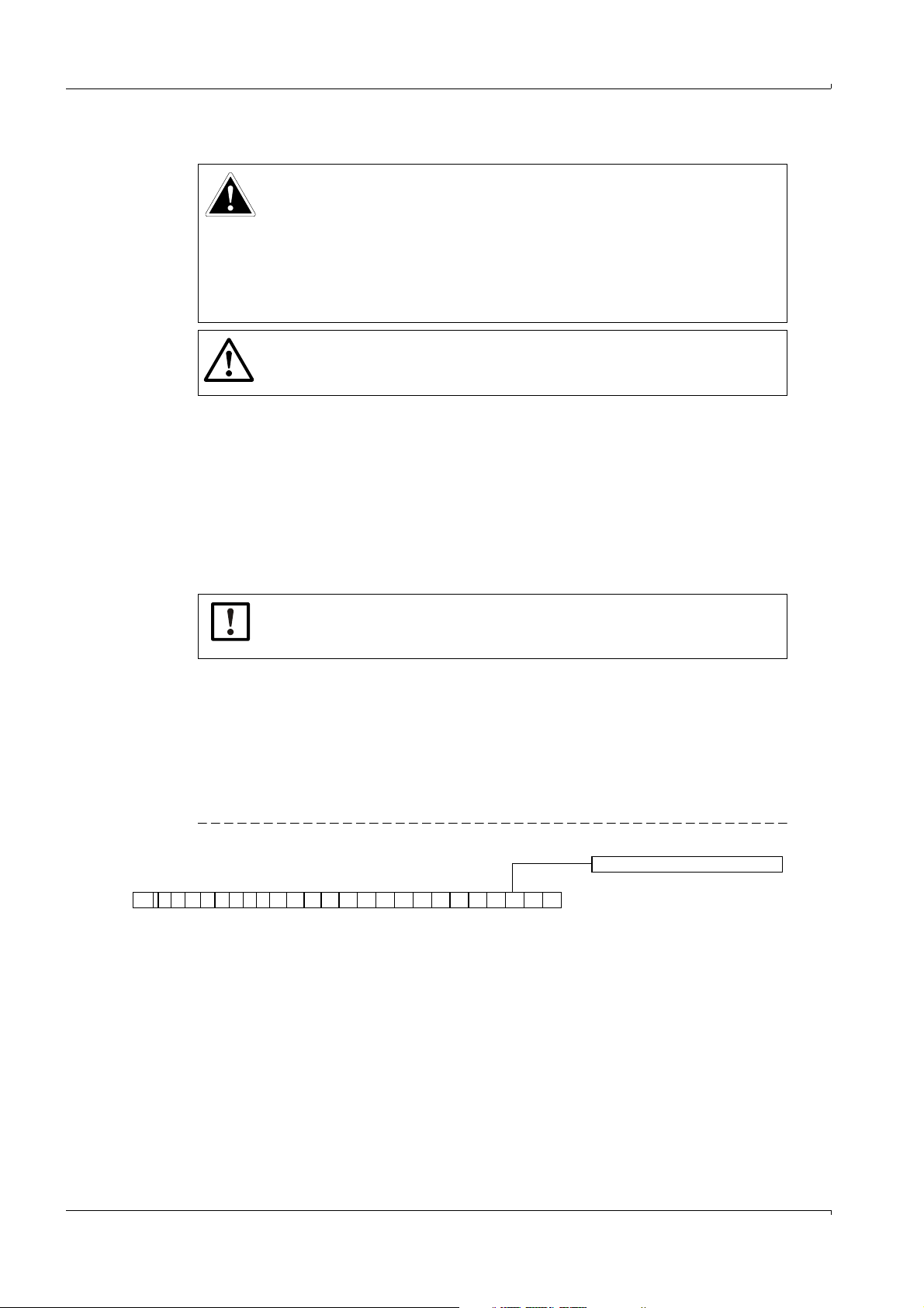
Fig. 1 Ty pe co d e
▸
For a complete description of the type code refer to → p. 112, §9.2.
NOTICE: Interface Configurations
This document only applies to FLOWSIC500 gas flow meters with optically isolated inputs and outputs.
2523 24
10 FLOWSIC500 · Operating Instructions · 8015391/Z261/V2-3/2016-10 · © SICK Engineering GmbH
Subject to change w ithout notice
Page 11

Important Information
5
3
1 Type plate, metrological and electrical parameters
(metrology and electronics)
4 Type plate, electrical parameters (electronics)
2 Pin assignment of plug-in connectors 5 Type plate, metrological parameters (metrology)
3 Type plate PED
Labelling according to CSA
Labelling according to ATEX/IECEx
4
1
3
2
1.3 Intended use
1.3.1 Purpose of the device
The FLOWSIC500 serves for measuring the gas volume, volume flow rate and gas velocity
of natural gas in pipelines.
The FLOWSIC500 with optional volume conversion serves for measuring the gas volume
and converting the gas volume measured to base conditions as well as registering data on
meter readings, maximums and other data.
1.3.2 Product identification
Product name: FLOWSIC500
Manufacturer:
The type plates for metrological and electrical parameters are located on the gas flow
meter. The type plate for the Pressure Equipment Directive is located on the adapter.
Examples for the type plates see → p. 114, § 9.3.
SICK Engineering GmbH
Bergener Ring 27
01458 Ottendorf-Okrilla
Germany
Fig. 2 Location of type plates
Subject to change w ithout notice
FLOWSIC500 · Operating Instructions · 8015391/Z261/V 2-3/2016-10 · © SICK Engineering GmbH 11
Page 12
1.3.3 Operation in potentially explosive atmospheres
The FLOWSIC500 is suitable for use in potentially explosive atmospheres:
ATEX: II 2G Ex ia [ia] IIB T4 Gb, II 2G Ex ia [ia] IIC T4 Gb,
IECEx: Ex ia [ia] IIB T4 Gb, Ex ia [ia] IIC T4 Gb,
US/C: Class I Division 1, Groups C, D T4, Ex/AEx ia IIB T4 Ga
Further information on potentially explosive atmospheres → p. 37, § 3.4.1.
1.3.4 Combustible gas
▸
The FLOWSIC500 is suitable for measuring combustible and occasionally ignitable
gases corresponding to zones 1 and 2.
1.3.5 Restrictions of use
▸
Refer to the type plate for the configuration of your FLOWSIC500.
▸
Check the FLOWSIC500 is suitably equipped for your application (e.g. gas conditions).
WARNING: Hazard through material fatigue
The FLOWSIC500 has been designed for use under mainly static loads.
▸
Maximum allowed gradient of static pressure: 3 bar/s (45psi/sec)
The number of complete pressure application and release processes should
be kept low during operation.
▸
Replace the device when 500 cycles have been reached.
Important Information
II 2G Ex op is IIC T4 Gb
Ex op is IIC T4 Gb
NOTICE:
The FLOWSIC500 is designed for measuring clean and dry natural gas.
▸
The operator should install a suitable filter or cone screen ahead of the gas
flow meter when the gas is contaminated.
NOTICE:
● The FLOWSIC500 is suitable for use in pressurized lines within the parameters specified in the device. The device complies with Pressure Equipment
Directive 2014/68/EU.
● It is the user's responsibility to ensure the maximum values specified for
pressure and temperature on the type plate are not exceeded during operation.
12 FLOWSIC500 · Operating Instructions · 8015391/Z261/V2-3/2016-10 · © SICK Engineering GmbH
Subject to change w ithout notice
Page 13
Important Information
1.3.6 Cleaning
WARNING: Risk of ignition due to electrostatic charge
Under certain extreme circumstances, in Gas Group IIC, exposed plastic and
unearthed metal parts of the enclosure may store an ignition-capable level of
electrostatic charge.
▸
Implement precautions to prevent the build up of electrostatic charge, e.g.
locate the equipment where a charge-generating mechanism (such as
wind-blown dust) might occur and clean with a damp cloth.
NOTICE: Cleaning instructions
▸
Only clean the FLOWSIC500 with a damp cloth.
▸
Do not use solvents for cleaning.
▸
Only use materials for cleaning which do not damage the surface of the
FLOWSIC500.
1.4 Responsibility of user
▸
Only put the FLOWSIC500 into operation after reading the Operating Instructions.
▸
Observe all safety information.
▸
If anything is not clear: Please contact the SICK Customer Service.
Designated users
The FLOWSIC500 may only be operated by skilled technicians who, based on their technical training and knowledge as well as knowledge of the relevant regulations, can assess
the tasks given and recognize the hazards involved.
NOTICE:
Skilled persons are persons in accordance with DIN VDE 0105 or IEC 364, or
directly comparable standards.
These persons must have exact knowledge on hazards arising from operation,
e.g. through hot, toxic, explosive gases or gases under pressure, gas-liquid
mixtures or other media as well as adequate knowledge of the measuring
system gained through training.
Correct use
▸
Only use the FLOWSIC500 as described in these Operating Instructions (→ p. 11, § 1.3.1).
The manufacturer bears no responsibility for any other use.
▸
Do not carry out any work or repairs on the FLOWSIC500 not described in this manual.
▸
Do not remove, add or change any components in or on the FLOWSIC500 unless such
changes are officially allowed and specified by the manufacturer.
Otherwise
– Any warranty by the manufacturer becomes void
– The FLOWSIC500 can become dangerous
– The approval for use in potentially explosive atmospheres is no longer valid
– The approval fur use in lines pressurized above 0.5 bar (7.25 psi) bar is no longer
valid.
Subject to change w ithout notice
FLOWSIC500 · Operating Instructions · 8015391/Z261/V 2-3/2016-10 · © SICK Engineering GmbH 13
Page 14

Danger identification on device
WARNING: Danger identification on device
The following symbol draws attention to important dangers directly on the
device:
▸
Consult the Operating Instructions in all cases where the symbol is
attached to the device or shown on the display.
Special local conditions
▸
Follow all local laws, regulations and company-internal operating directives applicable
at the installation location.
Retention of documents
These Operating Instructions must be
▸
Kept available for reference
▸
Passed on to new owners.
1.5 Additional documentation/information
Some parameter settings, components and characteristics depend on the individual
device configuration. This individual device configuration is described in the device documentation delivered with the device.
● Certificate of conformity/EX certificates (depending on configuration)
● Material certificate
● Inspection certificate
– Device configuration sheet
– Encoder test protocol (if configured)
– Low-pressure calibration test protocol (if ordered)
– Labels according to Pressure Equipment Directive 2014/68/EU, Annex 1 Part 3.3
● Printout of the Data Book
● Product CD with:
– Operating Instructions
– Operating program FLOWgate500
– FLOWgate500 Software Manual
–Key code
– Instructions for Kamstrup test valve BDA04
Important Information
14 FLOWSIC500 · Operating Instructions · 8015391/Z261/V2-3/2016-10 · © SICK Engineering GmbH
Subject to change w ithout notice
Page 15

Product Description
FLOWSIC500
2 Product Description
Operating principle
Device components
Meter sizes
Power supply
Interfaces
Device option: Volume conversion
Totalizers
Logbooks and Archives
Parameter protection
Sealing
Subject to change w ithout notice
FLOWSIC500 · Operating Instructions · 8015391/Z261/V 2-3/2016-10 · © SICK Engineering GmbH 15
Page 16
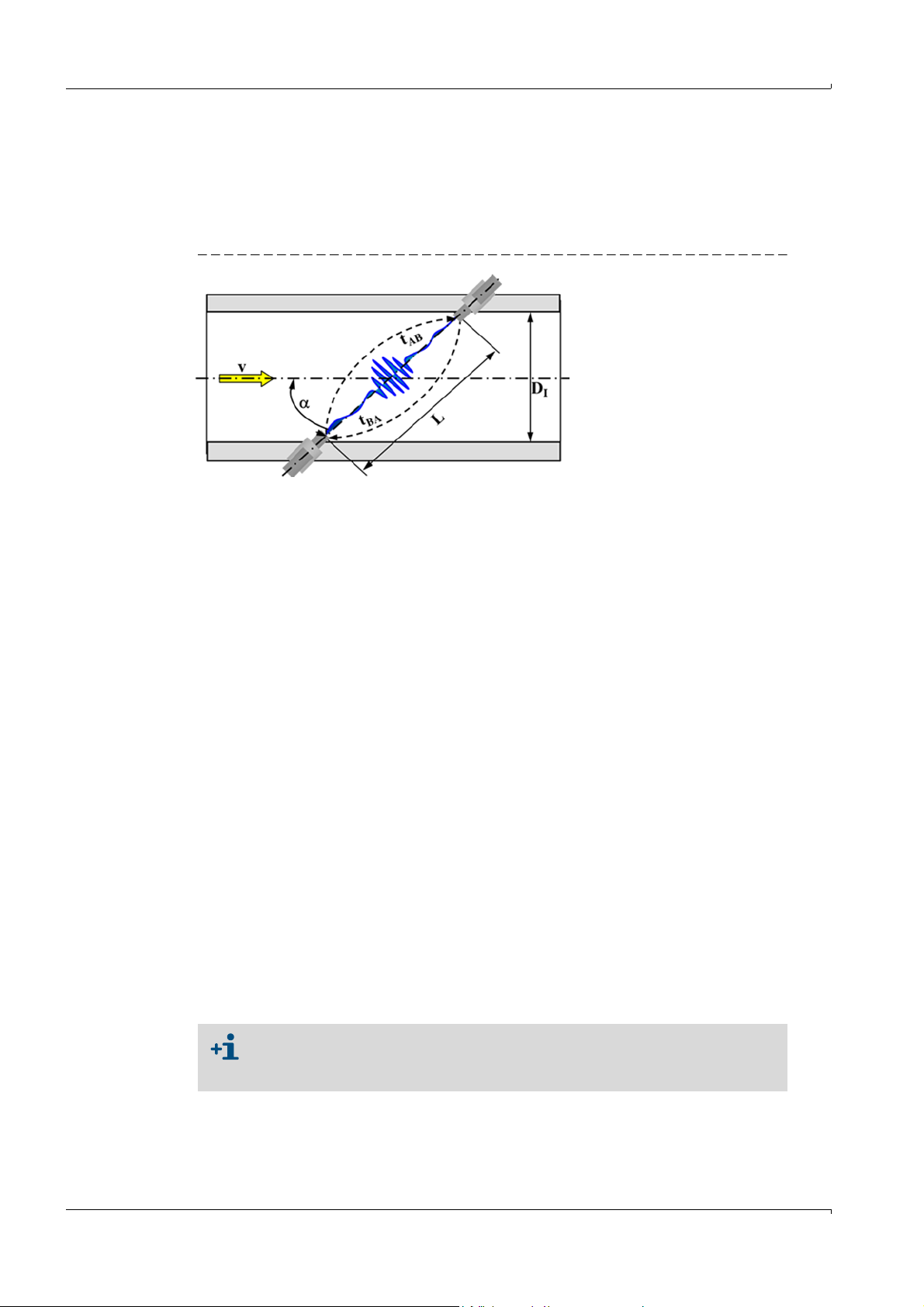
2.1 Operating principle
v= Gas velocity
L= Measuring path
= Angle of inclination in °
t
AB
= Sound transit time
in flow direction
t
BA
= Sound transit time
against flow direction
D
I
= Pipe inner diameter
Q= Volume flow
Q
4
-- -
D
I
2
L
2 cos
--------------- -
t
BAtAB
–
t
ABtBA
----------------------
=
V
b
CV
m
=
Vb= Volume at base conditions
C = Conversion factor
V
m
= Volume at measurement conditions
p = Gas pressure at measurement conditions
p
b
= Pressure at base conditions
T = Gas temperature at measurement conditions
T
b
= Temperature at base conditions
Z
b
= Compression factor at base conditions
Z = Compression factor at measurement conditions
C
p
p
b
-----
T
b
T
----- -
Z
b
Z
----- -
=
2.1.1 Gas flow meter
The FLOWSIC500 works according to the principle of ultrasonic transit time difference
measurement.
Fig. 3 Functional principle
Measured signal transit times tAB and tBA are defined by the current sound and gas velocity.
Gas velocity v is determined from the difference between the signal transit times. Therefore changes in the sound velocity caused by pressure or temperature fluctuations do not
affect the calculated gas velocity with this measurement method.
The FLOWSIC500 calculates the volume flow rate internally from the gas velocity and the
diameter of the measuring section of the gas flow meter.
Product Description
2.1.2 Volume conversion (optional)
The integrated volume conversion converts the measured gas volume from measurement
conditions to base conditions.
Calculation according to EN 12405:
The measurement conditions are either determined with pressure and temperature transmitters or entered as fixed value.
The following short forms are used in this document for better readability:
● Volume at base conditions = base volume
● Volume at measurement conditions = measurement volume
16 FLOWSIC500 · Operating Instructions · 8015391/Z261/V2-3/2016-10 · © SICK Engineering GmbH
Subject to change w ithout notice
Page 17
Product Description
Gas flow meter
Adapter
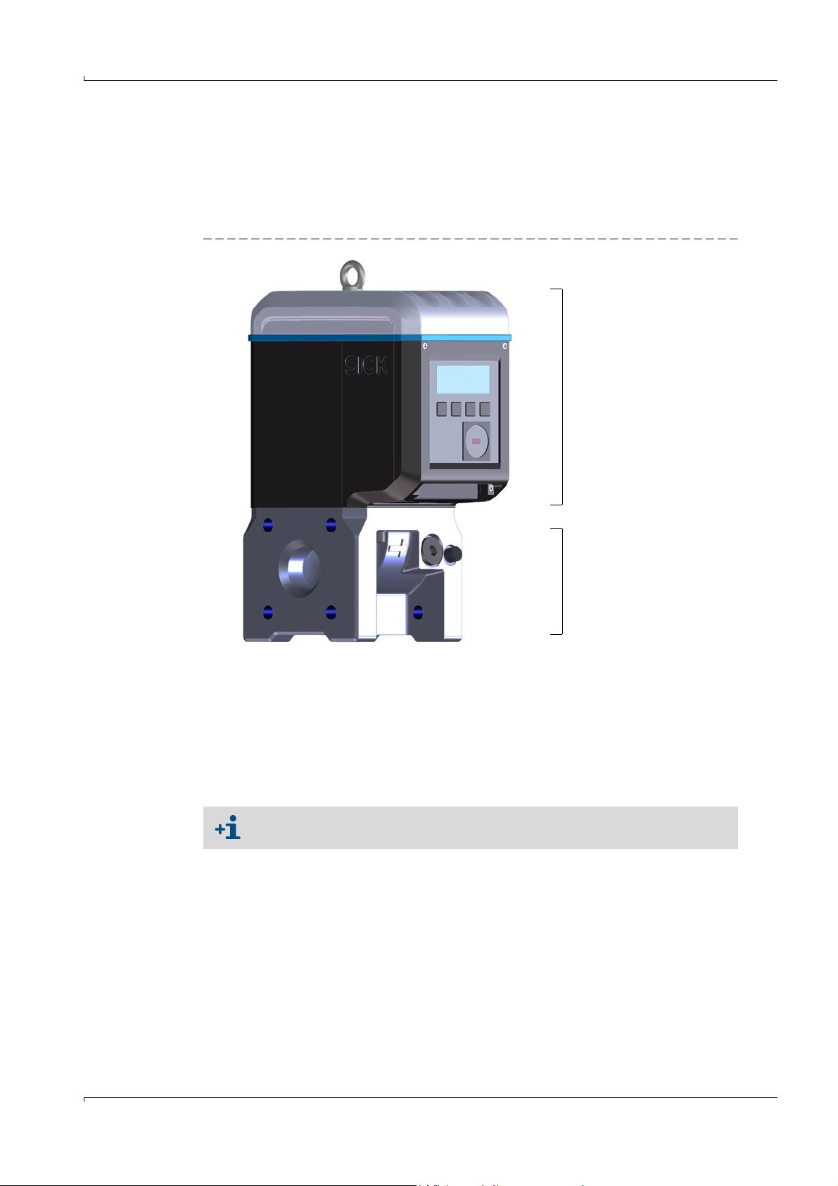
2.2 FLOWSIC500 measuring system
The FLOWSIC500 measuring system comprises:
● FLOWSIC500 gas flow meter,
● Adapter for installation in pipeline and
● optional p&T sensors for the volume conversion device option.
Fig. 4 FLOWSIC500 components
2.2.1
Adapter
The adapter is available in various flange standards and fitting lengths to connect the gas
flow meter to the system pipeline.
Depending on the version, the adapter is designed for assembly on line flanges PN16 in
accordance with DIN EN1092-1, CL150 in accordance with ASME B16.5, or 1.6MPa in
accordance with GOST 12815-80.
Fitting lengths available: → p. 117, § 9.4.
Subject to change w ithout notice
FLOWSIC500 · Operating Instructions · 8015391/Z261/V 2-3/2016-10 · © SICK Engineering GmbH 17
Page 18

2.2.2 Gas flow meter
An internal flow conditioner rectifies the gas flow in the gas flow meter so that flow profile
disturbances caused by pipe bends in the inlet or outlet sections or components projecting
into the pipe (e.g., a thermowell) have no influence on measuring results.
The gas flow meter can be replaced without taking the adapter out of the pipeline.
The gas flow meter is fitted with:
● Control unit
● Optical and electrical interfaces
● Measuring cell with ultrasonic transducers
● Electronics.
The product variant with volume conversion and integrated pressure and temperature
transmitters also has the calibrated pressure transmitter and calibrated temperature
transmitter fitted in the gas flow meter.
2.3 Meter sizes
Available meter sizes → p. 117, §9.4.
2.4 Power supply
The FLOWSIC500 is available with two configurations:
● For operation with external intrinsically safe power supply with backup battery (backup
duration: Approx. 3 months).
● Self-sufficient power configuration: 2 internal longlife battery packs (typical service life:
At least 5 years).
The second battery pack is activated automatically when the first pack is empty and a
message displayed (→ p. 58, § 5.2).
Product Description
2.5 Interfaces
The FLOWSIC500 supports various digital and serial interfaces.
The configuration of the interfaces as delivered is described in the delivery documents pro-
vided with the respective device.
Table 1 Interface configurations
Config. 1 (LF) Config. 2 (HF) Config 3 (Encoder + LF) Config. 4 (RS485) Config. 5 (Encoder + HF)
Type code I/O: F Type code I/O: G Type code I/O: H Type code I/O: I or J Type code I/O: K
DO_0 - HF pulses Encoder - Encoder
DO_1 Normal mode: Diagnosis warning, test mode: Test pulses HF pulses
DO_2 LF pulses - - - DO_3 Malfunction Malfunction LF pulses - Malfunction
Serial - - RS485 -
● Information on explosion-technical characteristics and rated voltage
→ p. 37, § 3.4.
● Details on standard interface configurations available → p. 42, § 3.4.6.
Subject to change w ithout notice
18 FLOWSIC500 · Operating Instructions · 8015391/Z261/V2-3/2016-10 · © SICK Engineering GmbH
Page 19
Product Description
2.5.1 Pulse and status outputs
FLOWSIC500 has 4 digital switching outputs. Digital switching outputs DO_0, DO_2 and
DO_3 are electrically isolated according to EN 60947-5-6.
Alternatively, digital switching outputs DO_2 and DO_3 can also be configured as Open Collector.
When used as pulse output, maximum 2 kHz can be output on digital switching output
DO_0 and maximum 100 Hz on digital switching outputs DO_2 and DO_3. When used as
status output, status information "Validity of measurement" or the result of the self-diagnosis can be represented.
Digital switching output DO_1 is not electrically isolated. In normal mode, the diagnosis
warning is output on DO_1, test pulses are output in test mode.
The digital switching outputs are updated synchronously once per second.
2.5.2 Encoder totalizer
Alternatively, NAMUR switching output DO_0 can be configured so that the reading of totalizer Vm, the meter status and a meter identification are output via asynchronous serial
communication. This allows the connection of volume convertors with a suitable input for
encoder totalizers.
NOTICE:
If encoder communication has been configured, ensure that the transferred
number of digits and the counter resolution can be processed by a connected
volume converter.
When the parameter locking switch is open, a parameter change can be performed at the FLOWSIC500 using the FLOWgate500 operating software.
2.5.3 Serial data interface
The serial interface is designed as externally powered RS485 and requires an external
intrinsically safe power supply for operation. The RS485 interface has no internal line termination.
2.5.4 Optical data interface
An optical interface according to IEC 62056-21 with serial bit, asynchronous data transmission is located on the front of the FLOWSIC500.
The interface can be used to read out data and parameter settings and to configure the
FLOWSIC500.
Subject to change w ithout notice
FLOWSIC500 · Operating Instructions · 8015391/Z261/V 2-3/2016-10 · © SICK Engineering GmbH 19
Page 20

2.6 Device option: Volume conversion
2.6.1 Volume conversion
The FLOWSIC500 gas flow meter with volume conversion captures the gas volume under
measurement conditions and converts it to a volume under base conditions.
Gas volume conversion can run selectively (set at the factory) as PTZ or TZ volume conversion: The configuration as temperature volume conversion uses the default value for measurement pressure for calculations.
Measurement conditions are recorded with the pressure and temperature transmitters or
entered as fixed values.
By default, measured values recording and subsequent conversion to the volume under
base conditions are performed every 30 seconds. The update interval can be adjusted
→ p. 69, § 5.2.6.5, “Calculation”.
Depending on the configuration, the compressibility factor (K-factor) is determined with
one of the following calculation methods or can be entered as a fixed value.
● SGERG88,
● AGA 8 Gross method 1
● AGA 8 Gross method 2
● AGA NX-19
● AGA NX-19 mod.
● Fixed value
The FLOWSIC500 checks the permissible entry limits of the parameters for the selected
calculation method. If one of the entry values is outside the limit values, the FLOWSIC500
switches to malfunction state and uses the fixed value of the compressibility factor for calculation of the basis volume.
An absolute pressure transmitter EDT 23 (optional: relative pressure transmitter EDT 23)
and a temperature transmitter EDT 34 measure current measurement conditions and
transfer the transmitter type, measured value as well as the transmitter status via a digital
interface.
The FLOWSIC500 reads the valid measuring range automatically and, periodically, the current status and measured value.
A transmitter is only activated for measurement when the configured serial number
matches the serial number transferred for the transmitter.
If no transmitter is detected or a transmitter is not functioning correctly, the
FLOWSIC500 automatically uses the stored default value (= fixed value) of the state vari-
able.
In this case, the FLOWSIC500 switches to malfunction state and, using the default value,
stores the volume under base conditions calculated for pressure or temperature in the
error volume counter.
If not specified otherwise, the FLOWSIC500 is supplied with the following standard settings:
Table 2 Standard settings
Unit system SI Imperial
T unit °C ° F
P unit bar psi
Symbols according to EN 12405 API
Calculation method SGERG88 AGA 8 Gross method 1
Reference conditions for den-
sity and heating value
(T1/T2/p2)
25 °C/0 °C/1.01325 bar (a)
Base pressure 1.01325 bar (a) 14.7300 psi (a)
Base temperature 0 °C 60 °F
Product Description
Subject to change w ithout notice
(T1/T2/p2)
60 °F/60 °F/14.7300 psi (a)
20 FLOWSIC500 · Operating Instructions · 8015391/Z261/V2-3/2016-10 · © SICK Engineering GmbH
Page 21
Product Description
1 Pressure transmitter
2 Kamstrup test valve BDA04
3 Temperature transmitter
2
3
1
2.6.2 Integrated pressure and temperature transmitters
The FLOWSIC500 with volume conversion and integrated pressure and temperature transmitters does not have any external components. The internal pressure and temperature
transmitters are already fitted and calibrated at the factory. The measuring ports are
located in the gas flow meter.
This means the FLOWSIC500 does not require any additional installation of transmitters to
determine the measurement conditions and is immediately ready for operation after volume conversion has been configured.
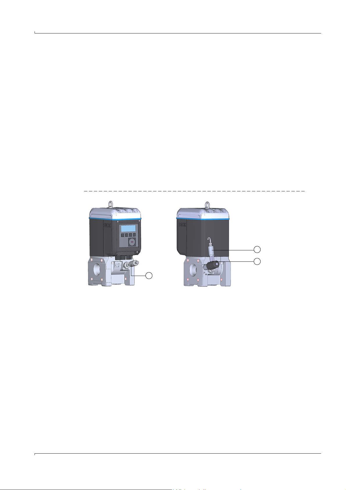
2.6.3 External pressure and temperature transmitters
The FLOWSIC500 with volume conversion and external transmitters is used at measuring
ports where a test/calibration of the pressure or temperature transmitter in the system
may be required.
It is recommended to install a three-way test valve that separates the pressure transmitter
from the measurement pressure and provides a test connection to test the pressure transmitter.
→ Fig. 5 shows a FLOWSIC500 with external transmitters and Kamstrup test valve BDA04
for gas temperatures to -25°C.
Fig. 5 FLOWSIC500 with external transmitters and Kamstrup test valve BDA04
A three-way test valve (→ Fig. 6) that is fitted next to the FLOWSIC500 is used for gas temperatures to -40°C.
Subject to change w ithout notice
FLOWSIC500 · Operating Instructions · 8015391/Z261/V 2-3/2016-10 · © SICK Engineering GmbH 21
Page 22
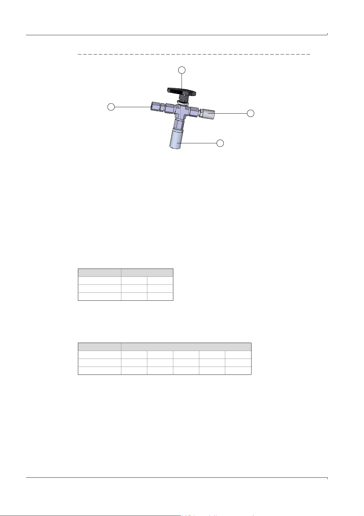
Fig. 6 Three-way test valve with p transmitter and Minimess coupling
1FLOWSIC500 connection
2 Three-way test valve
3 Test connection (Minimess coupling)
4 Pressure transmitter
1
2
3
4
Product Description
2.7 Totalizers
2.7.1 Device status and totalizers used
Various volume totalizers are fitted on the FLOWSIC500 depending on the configuration.
Meter V is used in the configuration as gas flow meter. If the gas flow meter has a malfunc-
tion, the measured volume is also recorded in the error volume counter errV.
Table 3 Device status and totalizers used
Status Totalize r
VerrV
Operation
Malfunction
●
●●
A gas flow meter Vm, a base volume meter Vb and a total volume meter Vbtot are used in
the configuration as gas flow meter with integrated volume conversion (device option). If
malfunctions occur, the measured values are not recorded in the base volume meter Vb,
but the converted volume is recorded in the error volume meter errVb.
Table 4 Device status and totalizers used (with device option volume conversion)
Status Totalize r
Vb errVb Vbtot Vm errVm
Operation
Malfunction
Authorized users (user level "Authorized user") can reset the error volume counters → p. 73,
§5.2.11.
●●●
●●●●
22 FLOWSIC500 · Operating Instructions · 8015391/Z261/V2-3/2016-10 · © SICK Engineering GmbH
Subject to change w ithout notice
Page 23

Product Description
2.7.2 Reverse flow
The FLOWSIC500 is designed as unidirectional type and has a configurable zero-flow cutoff
which is factory set to a value of 1 m
The totalizers are stopped during reverse flow and this volume is counted in a separate buffer totalizer. When normal operation resumes, the buffer totalizer is first computed with the
flow.
The totalizers are first incremented again after the reverse flow volume has passed
through.
During reverse flow, the meter first switches to malfunction when the preconfigured buffer
volume has been exceeded. An error message is output on the device.
2.8 Logbooks and Archives
The integrated data registration stores meter readings, maximums and other data in the
following archives:
● Measuring period archive
Totalizers and data saved after the measuring period elapses (standard = 60 min.). The
measuring period can be adjusted → p. 71, §5.2.6.9.
● Daily archive
Totalizers and data saved at the defined gas hour time (standard = 06:00)
● Monthly archive
Totalizers and data saved at the defined gas day time (standard = 1st day of month)
3
(35 ft3) as default.
Explanations on data structure and storage depth are available in Technical
Bulletin "Data Registration").
The FLOWSIC500 stores events and parameter changes in the following logbooks:
● Event logbook
All events with timestamp, user logged on and totalizer reading, max. number of
entries: 1000
When the Event logbook is 90% full, the FLOWSIC500 changes to device status "Warn-
ing", warning W-2001 is shown on the display.
When the Event logbook is full, the FLOWSIC500 changes to device status "Malfunc-
tion", error E-3001 is shown on the display (→ p. 78, § 6.2, “Status messages”).
● Parameter logbook
All parameter changes with timestamp, user logged on, totalizer reading and old and
new parameter value, max. number of entries: 250
The oldest entries are overwritten when the Parameter logbook is full.
● Metrology logbook
All changes to selected calibration-relevant parameters (→ p. 24, §2.9.2), with parameter
locking switch activated with timestamp, user logged on, totalizer reading and old and
new parameter value, max. number of entries: 100
When the Metrology logbook is full, calibration-relevant parameters can be modified
only after the parameter locking switch has been opened. The FLOWSIC500 changes to
device status "Warning", warning W-2002 is shown on the display (→ p. 78, § 6.2, “Status
messages”).
Subject to change w ithout notice
The data are stored in non-volatile memory. All logbooks can be viewed, stored and reset
with operating software FLOWgate500. The Event logbook can be viewed after logon as
"User" or "Authorized user" on the device.
FLOWSIC500 · Operating Instructions · 8015391/Z261/V 2-3/2016-10 · © SICK Engineering GmbH 23
Page 24
The following parameters are displayed:
EXT. POWER
BAT1
N.c.
DO3
DO0
+-
RS485
*
-
+
-
+
A
B
P1P2T1
T2
SENSORS
DISPLAY
LOCK
OFF ON
5..12V
NAMUR
4,5..16V
1.5 mm²
(AWG 16)
W
R :100
S
2..16V
2..16V
4074419
DO2
*Optional
V see module
CC
.
OC NAM
UR
2..16V
DO1
+-
BAT2
+-
+-
OC NAM
UR
+- +-
● Event type
● Number of events
● Short description
● Timestamp
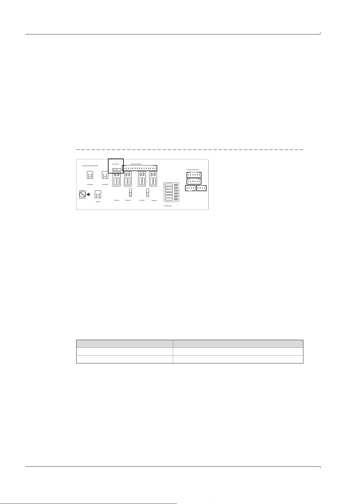
2.9 Parameter protection
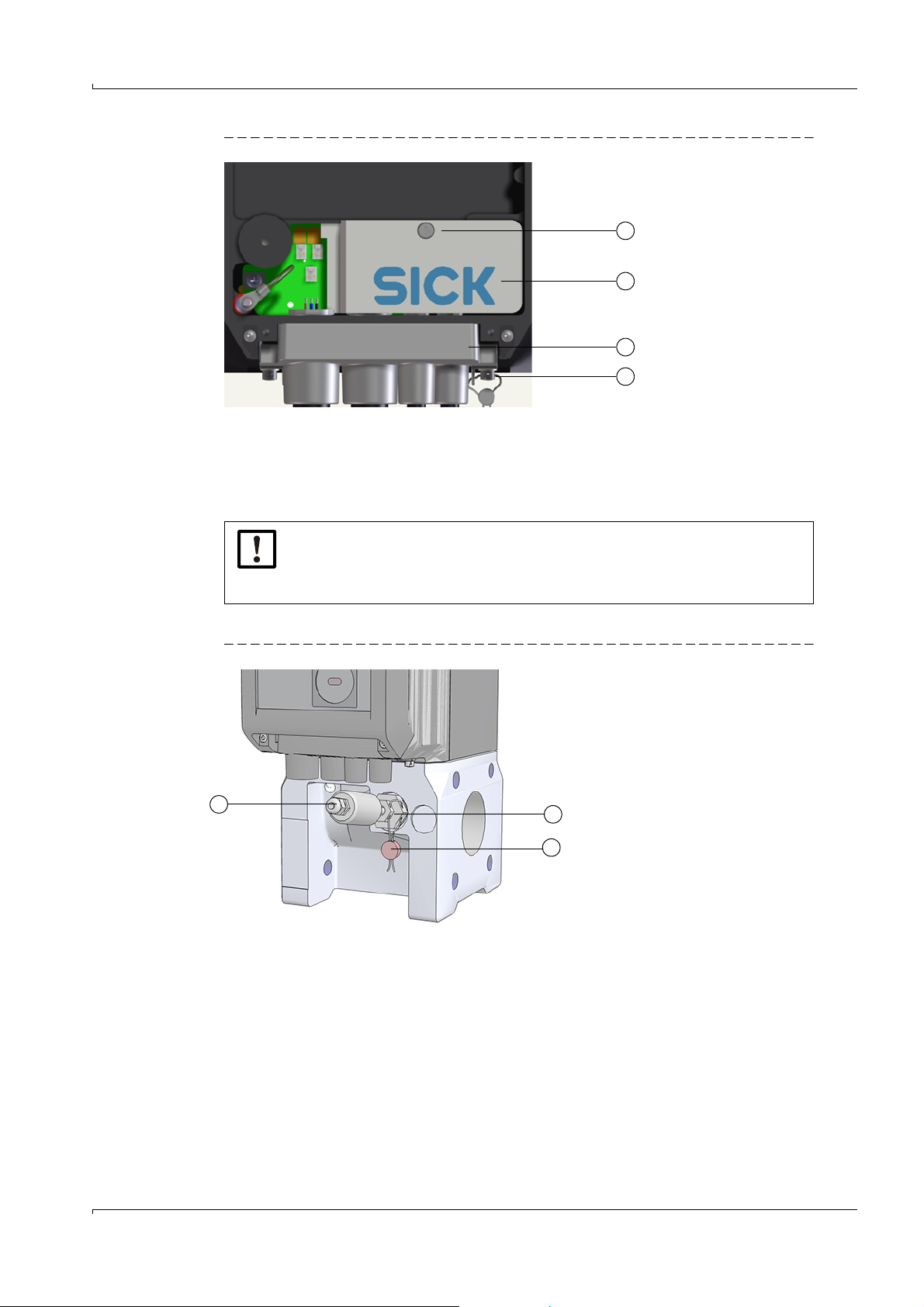
2.9.1 Parameter locking switch
A parameter locking switch is located on the circuit board to secure the calibration-relevant
parameters. This covers all values that influence volume metering and volume conversion.
Fig. 7 Parameter locking switch on the circuit board
Product Description
The parameter locking switch is secured by the terminal compartment cover and a seal.
2.9.2 Metrology logbook
Selected calibration-relevant parameters can be modified when the parameter locking
switch is closed and after logging in as authorized user.
To ensure traceability of these parameter changes, an entry is created in the Metrology logbook. This entry contains the timestamp, old and new value of the parameter changed,
meter reading V (for gas flow meters) or Vb (for gas flow meters with device option volume
conversion) and the logged on user.
The Metrology logbook can have a maximum of 100 entries. The FLOWSIC500 switches to
status "Warning" when the Metrology logbook is full.
The Metrology logbook can be cleared when the parameter locking switch is open. Parameter changes to the following parameters are entered in the Metrology logbook as long as
entries are possible
Table 5 Calibration-relevant parameters - gas flow meter
Parameter Description
Reverse flow limit Buffer volume for reverse flow
Symbols for measured value displays Symbols used on the display (formula symbols)
24 FLOWSIC500 · Operating Instructions · 8015391/Z261/V2-3/2016-10 · © SICK Engineering GmbH
Subject to change w ithout notice
Page 25

Product Description
Tab le 6 Calibration-relevant parameters - gas flow meter with volume conversion
Parameter Description
Reverse flow limit Buffer volume for reverse flow
Symbols for measured value displays Symbols used on the display (formula symbols)
Flow - lower warning limit Lower warning limit for the flow which can be set by the cus-
tomer
Flow - upper warning limit Upper warning limit for the flow which can be set by the cus-
tomer
Calculation method Calculation method for the compressibility factor
Calculation interval Cycle time for updating measured values (pressure, tem-
perature) and calculation of the compressibility factor
Standard pressure Standard pressure
Standard temperature Standard temperature
Reference conditions Reference conditions for density and heating value
Atmospheric pressure Ambient pressure
K-factor (fixed) Figure for method "Fixed value" when the calculation of the
K-factor is incorrect.
CO2 CO
H2 H
N2 N
proportion in gas
2
proportion in gas
2
proportion in gas
2
Relative density Relation between gas density and air density under refer-
ence conditions
Reference density Gas reference density under reference conditions
Heating value Gas heating (under reference conditions)
Heating value unit Heating value unit
p Default value Fixed value of measurement pressure
p Unit Unit for pressure values, used for entry and display
p Lower alarm limit Lower warning limit for the pressure which can be set by the
customer
p Upper alarm limit Upper warning limit for the pressure which can be set by the
customer
p Unit Unit for pressure values
T Default value Fixed value of measurement temperature
T Unit Unit for temperature values, used for entry and display
T Lower alarm limit Lower warning limit for the temperature which can be set by
the customer
T Upper alarm limit Upper warning limit for the temperature which can be set by
the customer
T Unit Unit for temperature values, used for entry and display
Gas hour Billing hour for the day archive
Gas day Billing day for month archive
Measuring period Period for billing archive
Subject to change w ithout notice
FLOWSIC500 · Operating Instructions · 8015391/Z261/V 2-3/2016-10 · © SICK Engineering GmbH 25
Page 26
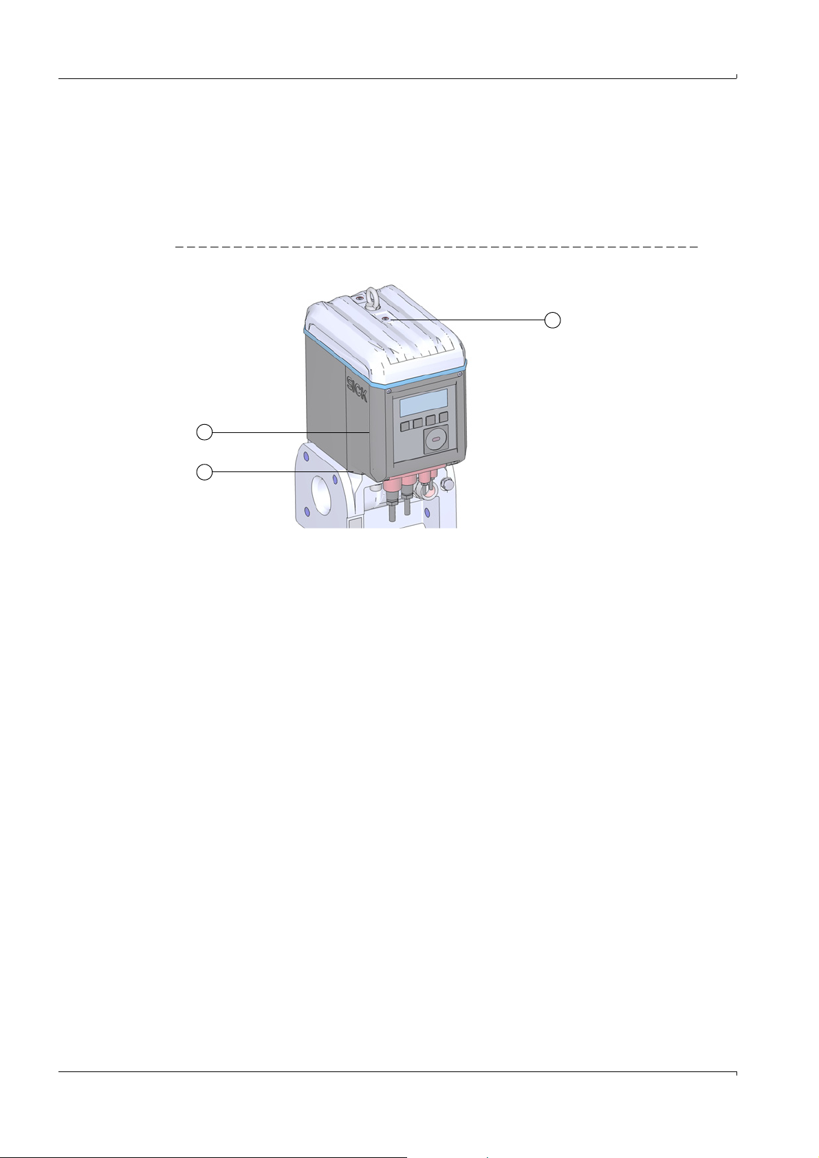
2.10 Sealing
1 Seal position
2 Possible position of the adapter seal
3 Possible position of the electronic cover seal
1
2
3
The FLOWSIC500 is secured at the factory with a seal on the cover.
Gas flow meter and adapter can be secured at the joint by a user seal (adhesive label)
glued with approximately equal spread on gas flow meter and adapter.
Optionally, the electronics cover can also be protected by the customer after the end of the
installation against unauthorized opening.
Fig. 8 Factory seal of the cover on the gas flow meter
Product Description
In addition, the FLOWSIC500 has seal positions on the terminal compartment cover and
the plug-in connector cover.
An adhesive label secures the interfaces and the parameter locking switch by the terminal
cover compartment.
During the start-up, the plug-in connector cover must be secured according to national regulations. This can be performed with an adhesive label which is glued with approximately
equal spread on the cover and the enclosure or alternatively by using capstan screws and a
tensioned sealing wire and a wire seal.
Subject to change w ithout notice
26 FLOWSIC500 · Operating Instructions · 8015391/Z261/V2-3/2016-10 · © SICK Engineering GmbH
Page 27
Product Description
1
2
1Seal position
2 Terminal compartment cover (securing the terminal compartment)
3 Plug-in connector cover
4 Capstan screw, wire and wire seal (securing of plug-in connector cover)
3
4
1 Temperature transmitter
2 Locknut
3Wire seal
3
2
1
Fig. 9 Seals on the terminal compartment and plug-in connector cover
NOTICE:
▸
Secure the terminal compartment cover and the plug-in connector cover
with at least one verification seal against unauthorized removal of the
cover!
Fig. 10 Seal on the temperature transmitter (example)
Subject to change w ithout notice
FLOWSIC500 · Operating Instructions · 8015391/Z261/V 2-3/2016-10 · © SICK Engineering GmbH 27
Page 28
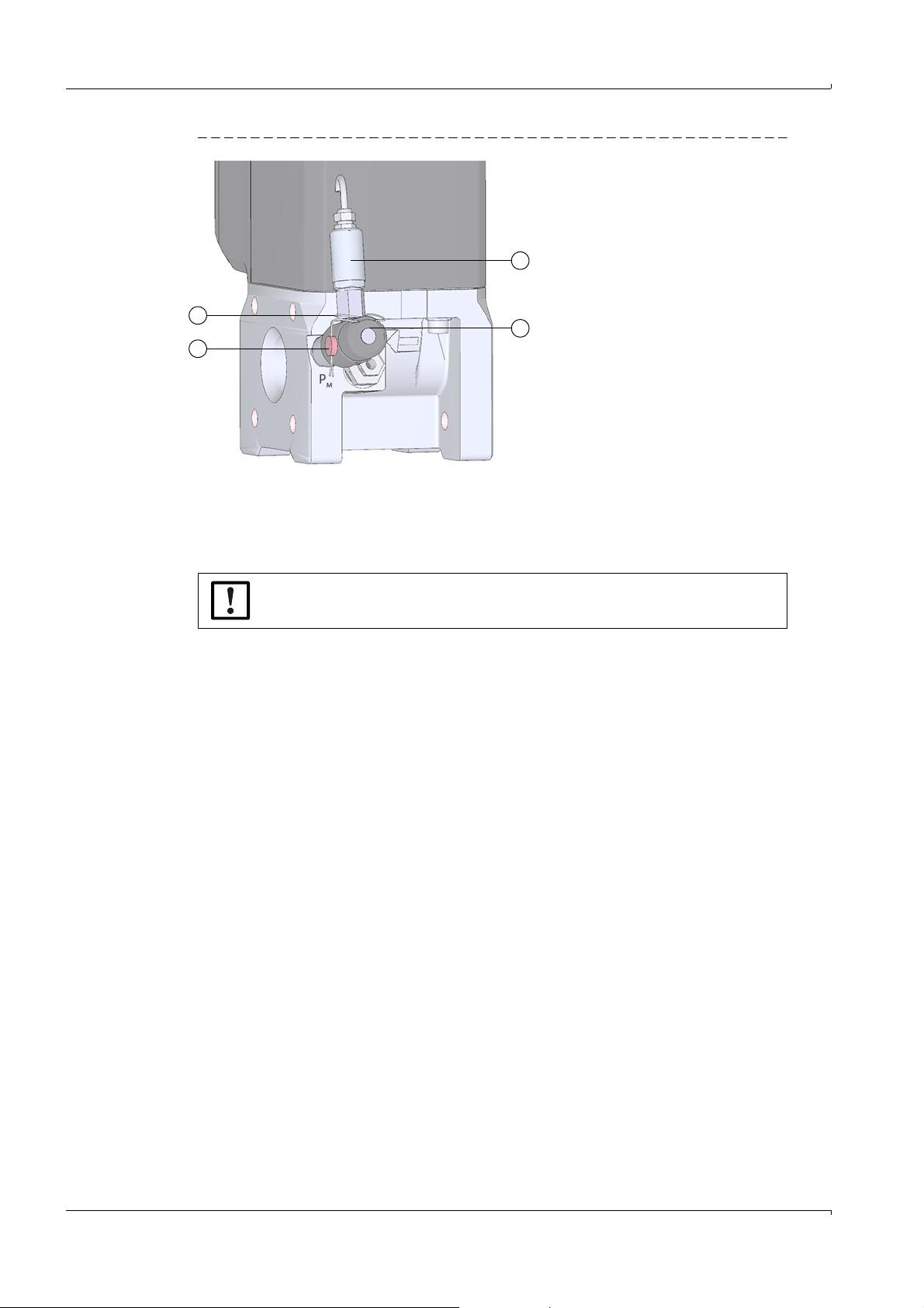
Fig. 11 Seal on the pressure transmitter (example)
1 Pressure transmitter
2 Kamstrup test valve BDA04
3Wire seal
4 Wire loop
3
1
2
4
Product Description
NOTICE:
Make sure that the wire loop is placed tight around the pressure transmitter.
28 FLOWSIC500 · Operating Instructions · 8015391/Z261/V2-3/2016-10 · © SICK Engineering GmbH
Subject to change w ithout notice
Page 29

Installation
FLOWSIC500
3 Installation
Hazards during installation
General information
Mechanical installation
Electrical installation
External pressure and temperature transmitters installation
Subject to change w ithout notice
FLOWSIC500 · Operating Instructions · 8015391/Z261/V 2-3/2016-10 · © SICK Engineering GmbH 29
Page 30
3.1 Hazards during installation
CAUTION: General risks during installation
▸
Observe applicable valid regulations, general standards and guidelines.
▸
Observe local safety regulations, operating instructions and special regulations.
▸
Observe the safety information in → p. 10, §1.1.
▸
Comply with the safety requirements of Pressure Equipment Directive
2014/68/EU or ASME B31.3 when installing pressure devices including
connection of various pressure devices.
▸
Persons carrying out installation work must be familiar with the directives
and standards applicable for pipeline construction and have the corresponding qualifications, e.g. in accordance with DIN EN 1591-4.
WARNING: Hazards through the gas in the system
The following conditions can increase the risk:
• Toxic gas or gas dangerous to health
•Explosive gas
• High gas pressure
▸
Only carry out installation, pre and repair work when the system is nonpressurized.
Installation
WARNING: Hazards during installation work
▸
Do not carry out any welding work on lines with meters fitted.
▸
Comply exactly with mandatory and approved methods.
▸
Observe and comply with regulations of the plant operator.
▸
Meticulously check completed work. Ensure leak tightness and strength.
Otherwise hazards are possible and safe operation is not ensured.
3.2 General information
3.2.1 Delivery
The FLOWSIC500 is delivered preassembled in sturdy packaging.
▸
Inspect for transport damage when unpacking the device.
▸
Document any damage found and report this to the manufacturer.
NOTICE:
Do not put the FLOWSIC500 into operation if you notice any damage!
▸
Check the scope of delivery for completeness.
The standard scope of delivery comprises:
● FLOWSIC500 (gas flow meter and adapter, already fitted),
● Backup battery (if device is configured for external power supply), or
● 2 battery packs (if device is configured for battery operation).
30 FLOWSIC500 · Operating Instructions · 8015391/Z261/V2-3/2016-10 · © SICK Engineering GmbH
Subject to change w ithout notice
Page 31

Installation
3.2.2 Transport
▸
During all transport and storage work, ensure:
– The FLOWSIC500 is always well secured
– Measures to prevent mechanical damage have been taken
– Ambient conditions are within specified limits.
3.3 Mechanical installation
CAUTION: General risks during installation
▸
Observe applicable valid regulations, general standards and guidelines.
▸
Observe local safety regulations, operating instructions and special regulations.
▸
Observe the safety information in → p. 10, §1.1.
▸
Comply with the safety requirements of Pressure Equipment Directive
2014/68/EU or ASME B31.3 when installing pressure devices including
connection of various pressure devices.
▸
Persons carrying out installation work must be familiar with the directives
and standards applicable for pipeline construction and have the corresponding qualifications, e.g. in accordance with DIN EN 1591-4.
The FLOWSIC500 normally does not need straight inlet and outlet sections and can be fitted directly after bends in the pipe.
NOTICE: Requirements on installation
▸
▸
▸
3.3.1 Preparations
▸
Select a suitable mounting location. Ensure adequate mounting clearances (→ Table 9).
▸
The following tools and materials are required to install the FLOWSIC500:
– Hoisting equipment (lifting capacity according to the weight specifications → p. 117,
§9.4)
– Box wrench with size suitable for flange installation
– Torque wrench
– Flange gaskets
– Anti-seize paste, metal-free or suitable for aluminium, e.g. OKS 235, to prevent
thread mountings seizing up
At a distance up to 5 DN upstream to the adapter, the following elements
must not occur:
– a valve which is not always fully open during operation,
– a pressure regulator.
The temperature sensor must not be disposed more than 5 DN down-
stream of the gas meter. The temperature sensor can be inserted in the
optional thermowells at the adapter alternatively.
In concrete application, observe limitations resulting from type approval!
NOTICE:
Do not use copper paste!
– 3 mm Allen key
Subject to change w ithout notice
FLOWSIC500 · Operating Instructions · 8015391/Z261/V 2-3/2016-10 · © SICK Engineering GmbH 31
– Leak detection.
Page 32
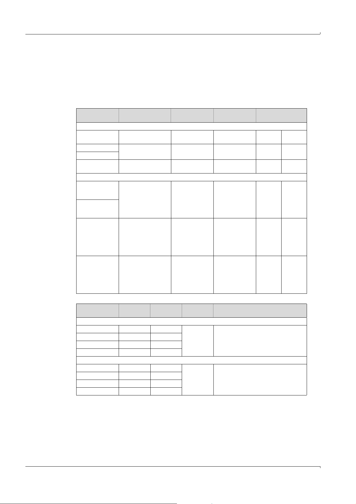
3.3.2 Choosing flanges, gaskets and other components
For flange connections only use pipeline flanges, bolts, nuts and gaskets suitable for the
maximum operating pressure, maximum operating temperature as well as ambient and
operating conditions (external and internal corrosion).
→ Table 7 contains a list of recommended bolts and → Table 8 contains a list of recom-
mended gaskets.
Table 7 Bolts and tightening torques
Device/flange
Bolts Washers Nuts Tightening torque
type
PN16 / EN1092-1
DN50/ PN16 4 pc. DIN835-
M16x45-A2-70
DN80/ PN16 8 pc. DIN835DN100/ PN16
M16x45-A2-70
DN150/ PN16 8 pc. DIN835-
M20x55-A2-70
4 pc. DIN125A17-A4
8 pc. DIN125A17-A4
8 pc. DIN125A21-A2
4 pc. ISO4032M16-A4-70
8 pc. ISO4032M16-A4-70
8 pc. ISO4032M20-A2-70
Class 150 / ASME B16.5
2"/ Cl150 4 pc. Double end
3"/ Cl150
4"/ Cl150 8 pc. Double end
6"/ Cl150 8 pc. Double end
Table 8 Gaskets
Device/flange
type
threaded stud Ø 5/8",
length 3.5"- ASME
B18.31.2,
ASTM A193 Grade
B8M
threaded stud Ø 5/8",
length 3.5"- ASME
B18.31.2,
ASTM A193 Grade
B8M
threaded stud Ø 3/4",
length 4.0"- ASME
B18.31.2,
ASTM A193 Grade
B8M
[1]
Da
[mm]
Di [mm] S [mm]
4 pc. Type A plain
washer (narrow
series) Ø 5/8" ANSI B18.22.1,
grade 8 stainless
steel
8 pc. Type A plain
washer (narrow
series) Ø 5/8" ANSI B18.22.1,
grade 8 stainless
steel
8 pc. Type A plain
washer (narrow
series) Ø 3/4" ANSI B18.22.1,
grade 8 stainless
steel
4 pc. Hex flat nut
(UNC series)
Ø 5/8" ANSI B18.2.2,
ASTM A194
Grade 8MA
8 pc. Hex flat nut
(UNC series)
Ø 5/8" ANSI B18.2.2,
ASTM A194
Grade 8MA
8 pc. Hex flat nut
(UNC series)
Ø 3/4" ANSI B18.2.2,
ASTM A194
Grade 8MA
Material
PN16 / EN1092-1
DN50/ PN16 107 61
DN80/ PN16 142 90
DN100/ PN16 162 115
2 novapress® FLEXIBLE/815
DN150/ PN16 218 169
Class 150 / ASME B16.5
2"/ Cl150 105 60
3"/ Cl150 137 89
4"/ Cl150 175 114
2 novapress® FLEXIBLE/815
6"/ Cl150 222 168
[1] Da = outer diameter, Di = inner diameter, S = thickness, → Fig. 12
Installation
130 Nm 96 lbf ft
130 Nm 96 lbf ft
250 Nm 184 lbf ft
140 Nm 103 lbf ft
140 Nm 103 lbf ft
240 Nm 177 lbf ft
32 FLOWSIC500 · Operating Instructions · 8015391/Z261/V2-3/2016-10 · © SICK Engineering GmbH
Subject to change w ithout notice
Page 33

Installation
Fig. 12 Dimensions of gaskets
Subject to change w ithout notice
FLOWSIC500 · Operating Instructions · 8015391/Z261/V 2-3/2016-10 · © SICK Engineering GmbH 33
Page 34

3.3.3 Fitting the FLOWSIC500 in the pipeline
Marking for flow direction
Direction of gas flow
NOTICE:
The lifting lug is designed for transporting the measuring device only.
Do not lift or transport the FLOWSIC500 with additional loads using this lug.
▸
The FLOWSIC500 must not swing or tilt on the hoisting equipment during
transport.
▸
The FLOWSIC500 must not turn during transport otherwise the lifting lug
could be screwed out.
NOTICE: Observe the gas flow direction
The prescribed flow direction is marked on the adapter with an arrow.
Arrow direction and gas flow direction must match.
▸
Install the FLOWSIC500 in flow direction.
The device signals a malfunction when the FLOWSIC500 is installed
against the prescribed flow direction.
The FLOWSIC500 can be installed horizontal or vertical.
The control unit can be rotated ± 90° (→ p. 40, § 3.4.4).
Fig. 13 Installation examples
Installation
34 FLOWSIC500 · Operating Instructions · 8015391/Z261/V2-3/2016-10 · © SICK Engineering GmbH
Subject to change w ithout notice
Page 35

Installation
1
1
2
2
1 Clearance at the top
2 Clearance at the bottom
3.3.3.1 Mounting clearances
Adequate mounting clearances must be maintained to ensure that sufficient space is available for exchanging the gas flow meter.
The clearance at the top is required for removing the gas flow meter and placing it back on
the adapter. The clearance at the bottom is required for loosening and removing or reinserting the screws and applying the tool accordingly.
Fig. 14 Mounting clearances
NOTICE:
Depending on the tools used and the mounting location, sufficient clearances
to the left and right must be ensured.
Tab le 9 Required minimum clearance based on the pipe axis
Meter size Clearance at the top,
without lifting lug
Clearance at the top,
with lifting lug
Clearance at the
bottom
[mm] [in] [mm] [in] [mm] [in]
DN50/2" 300 11.81 340 13.39 200 7.87
DN80/3" 460 18.11 510 20.08 250 9.84
DN100/4" 520 20.47 570 22.44 320 12.6
DN100/6" 520 20.47 570 22.44 320 12.6
Subject to change w ithout notice
FLOWSIC500 · Operating Instructions · 8015391/Z261/V 2-3/2016-10 · © SICK Engineering GmbH 35
Page 36

3.3.3.2 Torque on the pipeline
NOTICE:
If the FLOWSIC500 is installed so that the gas flow meter projects sideways
from the pipeline, the gas flow meter weight creates a torque on the pipeline.
▸
Make sure the pipeline is capable of holding the gas flow meter → p. 36,
Table 10.
Table 10 Pipeline torque
Meter size Torque
DN50/2" 6 5
DN80/3" 16 12
DN100/4" 31 23
DN150/6" 31 23
3.3.3.3 Installation in pipeline
1 Select suitable bolts.
Recommended bolts → Table 7.
2 Use the hoisting equipment to position the FLOWSIC500 in the desired location in the
pipeline.
Lay the pipelines without tension to the device to be installed!
3 Insert and align the gaskets.
4 Apply anti-seize paste to the bolts.
5 First screw the bolts by hand into the adapter to the stop.
– Screw in the bolts according to DIN835 with the shorter thread end.
– The bolts according to ASME B18.31.2 can be screwed in with any end.
6 Check the thread length in the adapter is fully utilized.
7 Then install the washers and nuts, and tighten them by hand.
8 Check whether the thread length of the nut is fully utilized.
If necessary, use a different bolt length.
9 Check correct positioning of flange gaskets.
10 Tighten nuts evenly and crosswise in small steps until the specified tightening torque is
reached (→ Table 7).
Make sure the flange sits free of tension.
11 Slowly increase the pressure in the pipeline.
Gradient: Max. 3bar/min (45psi/min)
12 Carry out a leak tightness check on the pipeline (in accordance with the pipeline manu-
facturer's specifications).
Installation
[Nm] [lbf ft]
36 FLOWSIC500 · Operating Instructions · 8015391/Z261/V2-3/2016-10 · © SICK Engineering GmbH
Subject to change w ithout notice
Page 37

Installation
3.4 Electrical installation
3.4.1 Requirements for use in potentially explosive atmospheres
The FLOWSIC500 is suitable for use in potentially explosive atmospheres:
ATEX: II 2G Ex ia [ia] IIB T4 Gb, II 2G Ex ia [ia] IIC T4 Gb,
IECEx: Ex ia [ia] IIB T4 Gb, Ex ia [ia] IIC T4 Gb,
US/C: Class I Division 1, Groups C, D T4, Ex/AEx ia IIB T4 Ga
For a FLOWSIC500 used in potentially explosive atmospheres:
▸
Installation, start-up, maintenance and inspection may only be carried out
by skilled persons having knowledge of the relevant rules and regulations
for potentially explosive atmospheres, especially:
– Ignition protection types
– Installation regulations
– Category classification
▸
Comply with all valid IEC standards.
The FLOWSIC500 is suitable for measuring combustible and occasionally ignitable gases
corresponding to zones 1 and 2.
Basic requirements
▸
The documentation for zone categorization in accordance with IEC60079-10 must be
available
▸
The FLOWSIC500 must have been checked for suitability for the actual installation location and the Ex marking on the device must match the requirements.
▸
After installation and before initial start-up, the complete equipment and the system
must be inspected in compliance with IEC 60079-17.
II 2G Ex op is IIC T4 Gb
Ex op is IIC T4 Gb
WARNING: Risk of explosion
All electrical connections of the FLOWSIC500 are approved for connection to
the certified intrinsically safe power circuits only.
▸
Proof of the intrinsic safety in compliance with IEC 60079-14 must be
presented for interconnection with the associated intrinsically safe equipment.
Otherwise the intrinsic safety of the FLOWSIC500 can be endangered, i.e.
the ignition protection for the FLOWSIC500 can no longer be ensured.
Subject to change w ithout notice
FLOWSIC500 · Operating Instructions · 8015391/Z261/V 2-3/2016-10 · © SICK Engineering GmbH 37
Page 38

Operating conditions for the ultrasonic sensors
● The pipeline contains a nonexplosive mixture. The gas mixture can be combustible.
● Gas pressure and gas temperature can be within the range
specified on the type plate of the
gas flow meter.
Case 2:
● The area inside the pipeline is classified as potentially explosive atmosphere Zone 1 or 2.
● The gas pressure must be within the
range 0.8 (11.6 psi) to 1.1 bar
(15.95 psi) (normal atmospheric
conditions).
● Gas temperature must be within the
permitted ambient temperature
range specified by the type plate on
the gas flow meter
Zone 1 or 2
Case 1:
Zone 1 or 2
Non-explosive gas mixture
Zone 1 or 2
The FLOWSIC500 is designed for use in potentially explosive atmospheres solely under
normal atmospheric conditions within the following limits.
– Ambient pressure range 0.8 bar (11.6 psi) to 1.1 bar (15.95 psi)
– Air with normal oxygen content, normally 21 percent by volume
The ambient temperature must be within the range specified on the type plate.
The gas flow meter becomes part of the pipeline as soon as the FLOWSIC500 is installed in
the pipeline.
The walls of the pipeline and the gas flow meter then serve as zone-separating barrier. The
following Figure shows the different situations for a possible application and the operating
conditions that apply.
Fig. 15 Ex zones
Installation
WARNING: Risk of ignition due to impact on the ultrasonic transducers
T
he ultrasonic transducers are manufactured from titanium. The pipeline
adaptor and part of the electronic enclosure may be made from aluminium. In
rare cases, ignition sources due to impact and friction sparks could occur.
The maximum piezo-electric energy released by impact on the ultrasonic transducers exceeds the limit for Gas Group IIC specified in Clause 10.7 of
EN60079-11:2012.
▸
For this reason, the ultrasonic transducers may only be used in zone 1
when risks of ignition arising from impacts or friction on the sensor housing
can be ruled out within the application.
▸
Only ultrasonic transducers provided by SICK may be used!
38 FLOWSIC500 · Operating Instructions · 8015391/Z261/V2-3/2016-10 · © SICK Engineering GmbH
Subject to change w ithout notice
Page 39

Installation
4 screws
3.4.2 Criteria for electrical connection
Installation work → p. 31, § 3.3 must be completed.
WARNING: Risk of explosion - hazard for intrinsic safety
▸
The following work may only be carried out by skilled technicians familiar
with the special characteristics of the intrinsic safety of the ignition protection type and who have knowledge of the relevant standards and regulations for interconnection of intrinsically safe power circuits.
3.4.3 Opening and closing the electronics cover
The Ex i terminal compartment of the FLOWSIC500 can be accessed after the
electronics cover has been opened. The cover may also be opened in the
hazardous area when under voltage. However, safe separation between the
various intrinsically safe power circuits must not be breached.
Opening the electronics cover
1 Loosen the 4 screws (captive) on the electronics cover using a 3 mm Allen key.
Fig. 16 Position of electronics cover screws
2 Open the electronics cover.
Closing the electronic cover
1 Close the electronics cover.
▸
Make sure no battery and display cables are pinched.
2 Screw the electronics cover tight again.
Tightening torque: 2.0 Nm (18 lbf in)
Subject to change w ithout notice
FLOWSIC500 · Operating Instructions · 8015391/Z261/V 2-3/2016-10 · © SICK Engineering GmbH 39
Page 40

3.4.4 Rotating the control unit
4 display screws
1 Open the electronics cover (→ p. 37, § 3.4)
2 Loosen the 4 display screws with a 3 mm Allen key, → Fig. 17.
Fig. 17 Position of display screws
Installation
3 Rotate the display in the desired direction.
4 Tighten the display screws evenly.
Tightening torque: 1.0 Nm (9 lbf in)
5 Close the electronics cover again.
40 FLOWSIC500 · Operating Instructions · 8015391/Z261/V2-3/2016-10 · © SICK Engineering GmbH
Subject to change w ithout notice
Page 41

Installation
1 2 3 4
1 Plug-in connector 1 (B-coded): External power supply and signal output
2 Plug-in connector 2 (A-coded): Signal output
3 Ground screw
4 Connections for pressure/temperature transmitters (optional)
1
2
4
3
1
2
4
3
Plug-in connector 1
(B-coded)
Plug-in connector 2
(A-coded)
3.4.5 Electrical connections
The FLOWSIC500 interfaces are accessible from the outside via external plug-in connectors.
Fig. 18 Connections
Fig. 19 M12 plug-in connector coding
NOTICE:
Safety relevant parameters are valid for connecting all pins of a plug-in connector.
Plug-in connector 2 (A-coded) can be configured when ordered, configuration
options → p. 42, §3.4.6.
The respective configuration is printed on the type plate ( → p. 43).
The external power supply need not be connected when the FLOWSIC500 is
operated with internal batteries.
Subject to change w ithout notice
FLOWSIC500 · Operating Instructions · 8015391/Z261/V 2-3/2016-10 · © SICK Engineering GmbH 41
Page 42

3.4.6 Pin assignment of plug-in connectors
3.4.6.1 Plug-in connector 1: External power supply and signal output
Table 11 Pin assignment for M12 plug-in connector 1 (male/B-coded, 4-poles)
M12 pin Input/output Function/signal Operating parameters
Safety relevant
parameters
1 PWR- Voltage supply Rated input voltage 4.5 … 16 V Ui = 20 V
I
= 667 mA
i
Pi = 753 mW
U
= 8.2 V
2PWR+
3 DO_1- Diagnosis warning,
pulse output in test mode
(→ Table 1) and in config-
4DO_1+
3.4.6.2 Plug-in connector 2: Signal output
Table 12 Pin assignment for M12 plug-in connector 2 (male/A-coded, 4-poles)
M12 pin Input/output Function/signal Operating parameters
Pin assignment configuration 1 LF pulses and malfunction (electrically isolated), Type code I/O: F
uration K,
f
= 2 kHz at 120 %
max
Q
max
1DO_2+ LF pulses
Passive, not electrically isolated
Max. 16 V
Max. 100 mA
R
< 110 Ω
on
R
> 1 MΩ
off
Passive, electrically isolated, configurable as:
f
configurable up to
2DO_2-
max
100 Hz at 120 % Q
3 DO_3- Malfunction
OC (Open Collector)*:
Max. 16 V
max
Rated current 20 mA
o
I
= 0.83 mA
o
Po = 1.7 mW
C
= 7,6 μF
o
L
= 100 mH
o
Safety relevant
parameters
= 20 V
U
i
P
= 753 mW
i
or NAMUR:
4DO_3+
Pin assignment configuration 2 : HF pulses and malfunction (electrically isolated), Type code I/O: G
1 DO_0+ HF pulses
f
configurable up to
2DO_0-
max
2 kHz at 120 % Q
max
Rated input voltage 8.2 V
I
= 3.4 mA
on
I
= 0.7 mA
off
NAMUR, electrically isolated, optically
isolated
Rated input voltage 8.2 V
I
= 3.4 mA
on
I
= 0.7 mA
off
U
= 20 V
i
P
= 753 mW
i
3 DO_3- Malfunction Passive, electrically isolated, configu-
rable as OC (Open Collector)* or
4DO_3+
NAMUR, see Configuration 1 for operating parameters
Installation
Pin assignment configuration 3 : Encoder and LF pulses (electrically isolated), Type code I/O: H
1 DO_0+ Encoder protocol NAMUR, electrically isolated, optically
isolated
2DO_0-
Rated input voltage 8.2 V
I
= 3.4 mA
on
I
= 0.7 mA
off
U
= 20 V
i
P
= 753 mW
i
3 DO_3- LF pulses Passive, electrically isolated, configu-
rable as OC (Open Collector)* or
4DO_3+
NAMUR, see Configuration 1 for operating parameters
* Standard configuration
42 FLOWSIC500 · Operating Instructions · 8015391/Z261/V2-3/2016-10 · © SICK Engineering GmbH
Subject to change w ithout notice
Page 43

Installation
(1) PWR+
(2) Data+
(3) GND
(4) Data-
(1) PWR+
(2) Data+
(3) GND
(4) Data-
Sensor
Sensor
1
2
4
3
1
2
4
3
(1)
(2) DO_2(3) DO_3(4)
Power
Signal output
(1)
(2)
(3)
(4)
PWRPWR+
DO_1DO_1+
A coded
1
2
4
3
1
2
4
3
B coded
DO_2+
DO_3+
Tab le 1 2 Pin assignment for M12 plug-in connector 2 (male/A-coded, 4-poles)
M12 pin Input/output Function/signal Operating parameters
Safety relevant
parameters
Pin assignment configuration 4: RS485 module (externally powered), Standard Version: Type code I/O: J, Low voltage
version: Type code I/O: I
1 PWR+ RS485 module
(externally powered)
2 Data A
3PWR-
Electrically isolated
Standard version:
Rated input voltage 4 … 16 V
Low voltage version:
U
= 20 V
i
P
= 1.1 W
i
IIC: C
IIB: Ci = 1.35 μF
L
= 0.03 mH
i
Rated input voltage 2.7 ... 10 V
4 Data B
Pin assignment configuration 5 : Encoder and HF pulses (not electrically isolated), Type code I/O: K
The HF pulses are output via plug-in connector 1 (DO_1), → Table 11.
= 0.22 μF
i
1 DO_0+ Encoder protocol NAMUR, electrically isolated, optically
isolated
2DO_0-
Rated input voltage 8.2 V
I
= 3.4 mA
on
I
= 0.7 mA
off
3 DO_3- Malfunction Passive, electrically isolated, configu-
rable as OC (Open Collector)* or
4DO_3+
NAMUR, see Configuration 1 for operating parameters
* Standard configuration
Fig. 20 Identification on the electronics type plate (example)
Internal terminal assignment→ p. 118, § 9.5
3.4.7
Cable specifications
When the plugs available from SICK are used, a shielded control cable with 4x0.25 mm
cross-section, with PVC insulation and approx. 5 mm outer diameter is required.
= 20 V
U
i
Pi = 753 mW
2
Subject to change w ithout notice
WARNING: Requirements on cables and installation
▸
Pay attention to the requirements in EN 60079-14 when selecting the
cables and during installation!
▸
Further legal requirements must be observed for use in explosive atmospheres.
SICK recommends the ready-made cables available as accessories (→ p. 104, §8.1).
FLOWSIC500 · Operating Instructions · 8015391/Z261/V 2-3/2016-10 · © SICK Engineering GmbH 43
Page 44

3.4.8 Operation with external power supply
1
1 External power supply and signal output
The FLOWSIC500 is designed electrically intrinsically safe.
▸
After correct installation has been checked, the plug connections in the
hazardous area can be connected and disconnected under voltage as well.
3.4.8.1 Connecting the external power supply
1 Connect the external intrinsically safe power supply to the M12 plug-in connector of the
FLOWSIC500.
Safety-relevant parameters → p. 42, §3.4.6.
Fig. 21 Connection for external power supply underneath the gas flow meter
Installation
2 Switch the power supply on.
The FLOWSIC500 is initialized.
3 Measurement starts and the current measured value for the gas volume appears.
4 Set the date and time (→ p. 54, §4.1).
3.4.8.2 Connecting the backup battery
1 Open the electronics cover (→ p. 39, 3.4.3).
2 Connect the back-up battery (part No. 2065928) to connection BAT2 in the terminal
compartment (→ Fig. 22).
3 Close the electronics cover again.
Fig. 22 Connected back-up batteries
Subject to change w ithout notice
44 FLOWSIC500 · Operating Instructions · 8015391/Z261/V2-3/2016-10 · © SICK Engineering GmbH
Page 45

Installation
3.4.9 Operation with batteries
WARNING: Risk of of ignition due to electrostatic charge
Make sure to minimize electrostatic risks when handling the plastic portable
battery packs.
▸
When a static-generating mechanism is identified, such as repeated brushing against clothing, take suitable precautions, e.g.the use of anti-static
footwear.
▸
Activities such as placing the item in a pocket or on a belt, operating a keypad or cleaning with a damp cloth, do not present a significant electrostatic
risk.
The FLOWSIC500 and the delivered battery packs are designed intrinsically
safe.
▸
Only the exchangeable battery packs from SICK with part no. 2064018 and
the backup battery with part no. 2065928 may be used.
▸
The battery packs can be connected and disconnected in the hazardous
area as well.
▸
Only connect the battery packs to the connections marked for this purpose
in the terminal compartment of the FLOWSIC500.
▸
Modifying the electrical connection parts is not allowed.
1 Open the electronics cover (→ p. 39, 3.4.3)
2 Insert the battery packs as shown and connect to connections BAT1 and BAT2 in the
terminal compartment.
The FLOWSIC500 is initialized.
Fig. 23 Connected battery packs
3 Close the electronics cover again.
4 Set the date and time (→ p. 54, §4.1).
Subject to change w ithout notice
FLOWSIC500 · Operating Instructions · 8015391/Z261/V 2-3/2016-10 · © SICK Engineering GmbH 45
Page 46
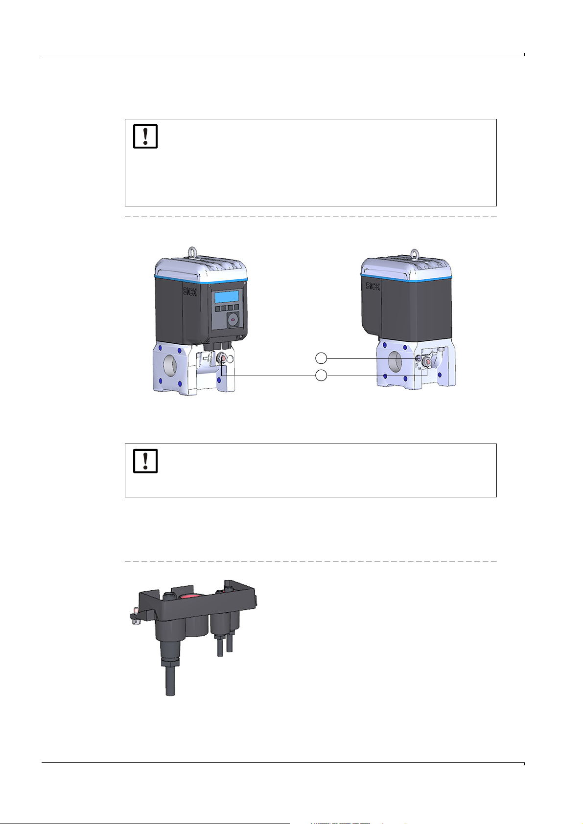
3.5 Installing the external pressure and temperature transmitters
1
2
1 Pressure measuring port
2 Alternative temperature measuring ports
The adapter of FLOWSIC500 has measuring ports for pressure and temperature.
NOTICE:
▸
The pressure measuring port to be used for measurement is marked “PM”.
On meters with flow direction “left-right” (→), the marked pressure measuring port is on the rear of the adapter, on meters with flow direction “rightleft” (←), it is on the front.
▸
Pressure and temperature transmitters can only be exchanged when the
parameter locking switch is open.
Fig. 24 Pressure and temperature measuring ports (front and rear side)
Installation
NOTICE: Ensure sufficient assembly clearance!
Ensure sufficient clearance to the wall or other components at the rear measuring ports when installing the transmitters.
The recommended minimum clearance to the wall is 0.3 m.
3.5.1
Fitting the plug-in connector cover
Fit the plug-in connector cover before installing the transmitters.
1 Guide the transmitter plugs through the openings in the plug-in connector cover.
Fig. 25 Plug-in connector cover
Subject to change w ithout notice
46 FLOWSIC500 · Operating Instructions · 8015391/Z261/V2-3/2016-10 · © SICK Engineering GmbH
Page 47

Installation
1 Connections for pressure and temperature transmitters
1
1
1
2
1 Capstan screw
2 Plug-in connector cover
2 Connect the plugs to the planned connections.
For meter sizes DN50 and DN80, it is recommended to connect the pressure
transmitter to the right M8 connection and the temperature transmitter to the
left M8 connection.
The FLOWSIC500 automatically detects whether a pressure or temperature
transmitter has been connected to a connection.
Fig. 26 Connections for pressure and temperature transmitters
3 Push the plug-in connector cover over the plugs and fasten with both capstan screws.
Fig. 27 Fastening the plug-in connector cover
Subject to change w ithout notice
FLOWSIC500 · Operating Instructions · 8015391/Z261/V 2-3/2016-10 · © SICK Engineering GmbH 47
Page 48

3.5.2 Installing the pressure transmitter
1 Pressure transmitter
2 Kamstrup test valve BDA04
1
2
A three-way test valve is normally fitted to be able to test the pressure transmitter.
NOTICE: Fitting information
It is recommended to connect the pressure transmitter with the three-way test
valve or with the FLOWSIC500 so that there is a downward slope from the pressure transmitter to the connection point and from the three-way test valve to
the FLOWSIC500.
Variant 1: Installation with Kamstrup test valve BDA04 (up to -25 °C)
For details on installation with Kamstrup test valve BDA04, see Kamstrup Operating Instructions.
You will find the document on the delivered product CD.
Installation
1 Remove the dummy plug on the pressure measuring port marked “P
2 Fit the Kamstrup test valve BDA04.
Pay attention to the alignment of the connection for the pressure transmitter.
3 Fit the pressure transmitter on the Kamstrup test valve BDA04 (→ Fig. 28).
Fig. 28 Kamstrup test valve BDA04 with pressure transmitter fitted
”.
M
48 FLOWSIC500 · Operating Instructions · 8015391/Z261/V2-3/2016-10 · © SICK Engineering GmbH
Subject to change w ithout notice
Page 49

Installation
FLOWSIC500
Pressure transmitter
FLOWSIC500
Test pressure
Pressure transmitter
Tab le 1 3 Kamstrup test valve BDA04 positions
Measuring position
Test position
Subject to change w ithout notice
FLOWSIC500 · Operating Instructions · 8015391/Z261/V 2-3/2016-10 · © SICK Engineering GmbH 49
Page 50

Variant 2: Installation with three-way test valve (to -40 °C)
1
2
3
4
1FLOWSIC500 connection
2 Three-way test valve
3 Test connection (Minimess coupling)
4 Pressure transmitter
Test pressure
FLOWSIC500
Test pressure
FLOWSIC500
Test pressure
FLOWSIC500
Here, a conventional three-way test valve is used.
Install the three-way test valve with pressure transmitter fitted at a suitable location next to
the FLOWSIC500. A pressure line serves to connect the pressure measuring connection of
the FLOWSIC500 to the three-way test valve.
1 Fasten the three-way test valve at a suitable location.
2 Remove the dummy plug on the pressure measuring port marked “P
3 Fit the supplied screw fitting.
4 Install the pressure line between the FLOWSIC500 and the three-way test valve.
5 Fit the pressure transmitter to the three-way test valve.
Fig. 29 Pressure transmitter installation on the three-way test valve (-40 °C)
Installation
”.
M
Table 14 Three-way test valve positions
Measuring position
Test position
Closed position
Subject to change w ithout notice
50 FLOWSIC500 · Operating Instructions · 8015391/Z261/V2-3/2016-10 · © SICK Engineering GmbH
Page 51

Installation
1 Pressure transmitter
1
Variant 3: Installation without a three-way test valve
Here, the pressure transmitter is connected directly to the FLOWSIC500.
1 Remove the dummy plug on the pressure measuring port marked “P
2 Fit the pressure transmitter.
Fig. 30 Installation without three-way test valve
”.
M
Subject to change w ithout notice
FLOWSIC500 · Operating Instructions · 8015391/Z261/V 2-3/2016-10 · © SICK Engineering GmbH 51
Page 52

3.5.3 Installing the temperature transmitter
1 Temperature transmitter
1
NOTICE:
SICK recommends to install the temperature transmitter on the temperature
measuring port which is on the same side as the display.
The temperature transmitter can be greased with heat-conductive oil or paste
to improve its performance.
1 Insert the temperature transmitter into the immersion sleeve to the stop.
2 Tighten the locknut.
3 Have the wire seal attached by a calibration inspector (→ Fig. 10).
Fig. 31 Installing the temperature transmitter
Installation
52 FLOWSIC500 · Operating Instructions · 8015391/Z261/V2-3/2016-10 · © SICK Engineering GmbH
Subject to change w ithout notice
Page 53

Start-up
FLOWSIC500
4 Start-up
Sequence of start-up
Setting the date and time
Configuring volume conversion (device option)
Checking the device status
Subject to change w ithout notice
FLOWSIC500 · Operating Instructions · 8015391/Z261/V 2-3/2016-10 · © SICK Engineering GmbH 53
Page 54

4.1 Sequence of start-up
4.1.1 Start-up of gas flow meter
FLOWSIC500 start-up is normally performed in the following sequence:
▸
Log on as "Authorized user" (→ p. 72, § 5.2.7).
▸
Set the date and time (→ p. 54, § 4.2).
▸
Check the device status (→ p. 56, § 4.4).
4.1.2 Start-up of gas flow meter with device option volume conversion
▸
Log on as "Authorized user" (→ p. 72, § 5.2.7).
▸
Set the date and time (→ p. 54, §4.2).
▸
Activate the configuration mode (→ p. 72, § 5.2.9).
▸
Set fixed values for pressure and temperature (→ p. 55, §4.3.1).
▸
Set reference values (already configured: → Table 2).
▸
Select the calculation method (already configured: → p. 69, §5.2.6.5)
▸
Set the fixed value of the compressibility factor (→ p. 69, §5.2.6.5).
▸
Check the configuration (→ p. 56, §4.3.3).
▸
Configure the gas composition (→ p. 56, § 4.3.3).
▸
Adapt alarm limits for pressure and temperature (→ p. 70, §5.2.6.6 and
→ p. 70, § 5.2.6.7).
Start-up
The alarm limits are set in the factory to the measuring range of the selected transmitter
▸
Terminate configuration mode (→ p. 72, § 5.2.9).
▸
Check the device status (→ p. 56, § 4.4).
4.2 Setting the date and time
Date and time must be set after the power supply has been connected. The FLOWSIC500
displays error E-3007 ("Time" invalid) until the time has been set.
Detailed information on operating using the display and on menu navigation
→ p. 58, § 5.2.
● The time zone function adapts the time to the new time zone.
If you want to change date and time as well as the time zone, change the
time zone first.
● Date and time can be changed without starting configuration mode.
1 Log on as "Authorized user" (→ p. 72, § 5.2.7).
2 Switch to the "System settings” submenu in the FLOWSIC500 menu.
3 Call up "Date".
4 Press ENTER to start the edit mode.
The cursor now blinks under the first position of the date.
5 Use the arrow buttons to increment or decrement the selected position by 1 until the
correct digit is shown.
6 Confirm with ENTER.
The cursor now blinks under the second position of the date.
7 Repeat for the remaining positions of the date.
The date is saved when you confirm the last position with ENTER.
Subject to change w ithout notice
54 FLOWSIC500 · Operating Instructions · 8015391/Z261/V2-3/2016-10 · © SICK Engineering GmbH
Page 55

Start-up
8 Switch to "Time".
9 Use the arrow buttons to increment or decrement the first position of the time by 1 until
the correct digit is shown.
10 Confirm with ENTER.
11 Repeat for the remaining positions of the time.
The time is saved when you confirm the last position with ENTER.
4.3 Configuring volume conversion (device option)
4.3.1 Setting fixed values
The fixed values must be set to the average measurement conditions of pressure and temperature:
1 Log on as "Authorized user" (→ p. 72, § 5.2.7).
2 Start the configuration mode → p. 72.
3 In the FLOWSIC500 menu, switch to submenu "Pressure parameters" or "Temperature
parameters"
4 Select the view "p Fixed value" or "T Fixed value".
5 Press ENTER to start the edit mode.
The cursor now blinks under the first position of the parameter.
6 Use the arrow buttons to increment or decrement the selected position by 1 until the
correct digit is shown.
7 Confirm with ENTER.
The cursor now blinks under the second position of the parameter.
8 Repeat for all remaining positions of the parameter.
The fixed value is saved when you confirm the last position with ENTER.
4.3.2 Checking the configuration
The FLOWSIC500 is delivered already configured according to customer specifications.
It is recommended to check the calibration-relevant parameters and settings. The calibra-
tion-relevant parameters are shown in the Data Book printout and can be compared
against the current configuration on the display.
A new printout of the Data Book can be created using the FLOWgate500 operating software.
Subject to change w ithout notice
FLOWSIC500 · Operating Instructions · 8015391/Z261/V 2-3/2016-10 · © SICK Engineering GmbH 55
Page 56

4.3.3 Configuring the gas composition
1 Log on as "Authorized user" (→ p. 72, § 5.2.7).
2 Start the configuration mode (→ p. 72).
3 Switch to submenu "Conversion/Gas composition" in the FLOWSIC500 menu.
4 Enter the following parameters according to the gas used and for the calculation
method selected:
– Rel. density or reference density
–H2 [mol%]
–CO2 [mol%]
–N2 [mol%]
–Heating value
Parameter changes are saved in the Metrology logbook when the parameter
locking switch is closed.
The Metrology logbook can be viewed using the FLOWgate500 operating software.
4.4 Checking the device status
Make sure the FLOWSIC500 is in error-free operating status:
1 Log on as "Authorized user" (→ p. 72, § 5.2.7).
2 Check whether warnings or errors are shown in the symbol bar on the display.
The device has a warning.
The FLOWSIC500 is in "Warning" status.
Start-up
The device has an error.
The FLOWSIC500 is in "Malfunction" status.
3 If warnings or malfunctions exist, change to view "Current events" on the main display:
– Clear existing malfunctions (→ p. 78, §6.2, “Status messages”).
– Contact SICK Customer Service for any malfunctions you cannot clear yourself
(→ p. 78, § 6.1, “Contacting Customer Service”).
4 The event overview can be reset when all warnings and errors have been cleared
(→ p. 73, § 5.2.12).
Subject to change w ithout notice
56 FLOWSIC500 · Operating Instructions · 8015391/Z261/V2-3/2016-10 · © SICK Engineering GmbH
Page 57

Operation
FLOWSIC500
5 Operation
Control unit
Operating using the display
Operating using the optical data interface
FLOWgate500 operating software
Parameter protection
Subject to change w ithout notice
FLOWSIC500 · Operating Instructions · 8015391/Z261/V 2-3/2016-10 · © SICK Engineering GmbH 57
Page 58

5.1 Control unit
1
3
2
1Display
2 Buttons
3 Optical data interface
Fig. 32 Operating and display elements
Operation
5.2
Table 15 Buttons
Operating using the display
▸
Press any button to switch the display on.
Esc
ENTER Calls a submenu, starts edit mode. Confirms an input.
In battery operation, the display and the optical data interface have a timeout
and switch off after approx. 60 seconds (default setting) when no button has
been pressed and no data transmission takes place.
The display and the optical interface are permanently active when an external
power supply is connected.
In menu In Edit mode
Returns to next higher level of the operator menu
Toggles between single menu entries
on one level
Aborts input of new value and returns
to the next higher level of the operator
menu.
Increments or decrements a parameter by 1, toggles between several selection options.
58 FLOWSIC500 · Operating Instructions · 8015391/Z261/V2-3/2016-10 · © SICK Engineering GmbH
Subject to change w ithout notice
Page 59

Operation
1
2
1
1
1
1
1
5.2.1 Display in the symbol bar
Tab le 1 6 Symbols
Symbol Significance Description
External power supply Only displayed when the device is configured with external
Battery fill level, battery 1 Displayed when the FLOWSIC500 is configured for battery
Battery fill level, battery 2 With external power supply: Backup battery status.
Device status: Malfunction The device has an error, the measured value is invalid.
Device status: Warning The device has a warning, the measured value is still valid.
Registered events Events have occurred since the last event summary reset.
power supply.
operation: Status of the first battery pack
Details on the battery fill level → p. 59, § 5.2.2.
With battery operation: Second battery pack status.
Details on the battery fill level → p. 59, § 5.2.2.
Parameter locking switch
closed
Parameter locking switch
open
Configuration mode Device parameters can be changed.
NOTICE:
In device status “Malfunction” or “Warning”, the respective symbols are shown
blinking on the display.
5.2.2 Battery fill level display
The battery symbol changes as the battery is discharged.
Tab le 1 7 Battery fill level display
Battery fill level > 75%
Battery fill level > 50%
Battery fill level > 25%
Battery fill level > 25%
Metrologically relevant parameters are protected against
changing; modifications are registered in the Metrology logbook → p. 24, § 2.9.2.
Metrologically relevant parameters can be changed; the modifications are not saved in the Metrology logbook.
Battery almost empty but still in use
● The last segment of the battery symbol starts to blink when the battery fill level drops
below 10%.
● When the battery is completely empty, the empty battery symbol blinks and the
FLOWSIC500 has switched to the second battery.
Subject to change w ithout notice
FLOWSIC500 · Operating Instructions · 8015391/Z261/V 2-3/2016-10 · © SICK Engineering GmbH 59
Page 60
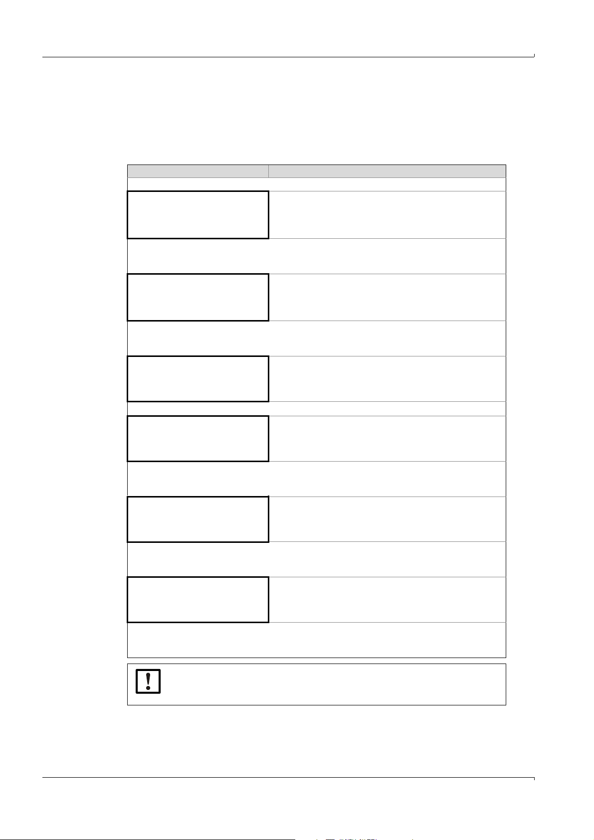
5.2.3 Main screen (without device option volume conversion)
▸
Use buttons and to toggle between the menu entries on a level.
▸
Press ENTER to go down one menu level.
Main display
The following information is displayed on the top display menu level:
Main display Description
Operation
V
000000000 m
20.08.2012 10:30:52
3
V = Volume absolute, cannot be reset
Pressing ENTER opens the FLOWSIC500 menu.
err
V
000000000 m
20.08.2012 10:30:52
3
err
V = Error volume: Volume counted during a malfunction, can be
reset
Pressing ENTER opens the action "Reset error volume”.
→ "Resetting the error volume" (p. 73).
Q = Volume flow
Q 0.000 m3/h
VOG 0.000 m/s
Current events
1 Event
VOG = Gas velocity
Current events (1 event is reported)
Pressing ENTER opens a list of current reported events.
Use the arrow buttons to toggle through the reported events.
Stored status messages: Events since the last time the event
Event Summary
2 Events
summary was reset (2 events have occurred).
Pressing ENTER opens a list of stored events.
Use the arrow buttons to toggle through the stored events.
Last Event Reset
20.08.2012 10:30:52
Last reset of event summary
Pressing ENTER opens the action "Reset Event Summary”.
→ "Resetting the event summary" (p. 73).
NOTICE:
A parameter with Malfunction status is shown on the display by a blinking
exclamation mark after the parameter (e. g. Q!).
60 FLOWSIC500 · Operating Instructions · 8015391/Z261/V2-3/2016-10 · © SICK Engineering GmbH
Subject to change w ithout notice
Page 61

Operation
Menu navigation (without device option volume conversion)
Some menu functions are only available when you are logged in with user level "User" or
"Authorized User":
User level: G Guest (standard) U User (1)
Access rights: - Hidden ○ View ● Star t/edit
Path G U A2+3 A1 Explanation
Main display: Volume under measurement conditions V ○○ ○ ○
FLOWSIC500 menu: User ○○ ○ ○
Logged in user level ●● ● ●→p. 67, §5.2.6.1
Login ●● ● ●
Logout - ●●●
FLOWSIC500 menu: Device mode ○○ ○ ○→p. 67, §5.2.6.2
Calibration mode ○○ ● ●
Configuration mode ○○ ● ●
FLOWSIC500 menu: Device information ○○ ○ ○→p. 67, §5.2.6.3
Measuring port ○○ ○ ○
Serial number ○○ ○ ○
Firmware Version ○○ ○ ○
Firmware Date ○○ ○ ○
Firmware CRC ○○ ○ ○
Metrology CRC ○○ ○ ○
Min. oper. pressure ○○ ○ ○
Max. oper. pressure ○○ ○ ○
Meter factor ○○ ○ ○
Frequency at Qr [Hz] ○○ ○ ○
FLOWSIC500 menu: System settings ○○ ○ ○→p. 68, §5.2.6.4
Power supply (1) [%] ○○ ● ●
Power supply (2) [%] ○○ ● ●
Date ○○ ● ●
Time ○○ ● ●
Timezone ○○ ● ●
Language ○● ● ●
Symbols ○○ ○ ○
LCD test ○● ● ●
FLOWSIC500 menu: Logbooks ○○ ○ ○
Event logbook ○○ ○ ○
List of stored events - ○○○
Parameter logbook ○○ ○ ○
Metrology logbook ○○ ○ ○
FLOWSIC500 menu: Archives ○○ ○ ○→p. 71, §5.2.6.9
Gas hour ○○ ● ●
Gas day ○○ ● ●
Measuring period ○○ ● ●
Main display: Error volumes errV ○○ ● ●
Main display: Volume flow under measurement
conditions/ gas velocity
Main display: Current Events ○○ ○ ○
List of current events ○○ ○ ○
Main display: Event Summary ○○ ○ ○
Subject to change w ithout notice
Main display: Last Event Reset ○○ ● ●→p. 73, §5.2.12
List of stored events ○○ ○ ○
User (2)
User (3)
○○ ○ ○
A1
Authorized user (1)
A2
Authorized user (2)
A3
Authorized user (3)
FLOWSIC500 · Operating Instructions · 8015391/Z261/V 2-3/2016-10 · © SICK Engineering GmbH 61
Page 62

5.2.4 Main display (with device option volume conversion)
▸
Use buttons and to toggle between the menu entries on a level.
Press ENTER to go down one menu level.
The symbols on the display are shown as standard in accordance with
EN12405.
Symbols with regional deviations can be configured.
These Operating Instructions use symbols in accordance with EN12405.
Main display (with device option volume conversion)
The following information is displayed on the top display menu level:
Main display Description
Operation
Vb
000000000 m
20.08.2012 10:30:52
3
Vb= Volume at base conditions, uninterrupted
Pressing ENTER opens the FLOWSIC500 menu.
err
Vb
000000000 m
20.08.2012 10:30:52
3
err
Vb = Error volume at base conditions
Pressing ENTER opens the action "Reset error volume”.
→ "Resetting the error volume" (p. 73).
totalV
20.08.2012 10:30:52
V
m
20.08.2012 10:30:52
err
20.08.2012 10:30:52
000000000 m
b
000000000 m
V
000000000 m
m
3
totalV
= Total volume at base conditions = Vb +
b
3
Vm = Total volume at measurement conditions
err
Vm = Error volume
3
Volume counted at measurement conditions, during a malfunction, can be reset
err
V
b
Q = Volume flow at measurement conditions
Q 0.000 m3/h
Qb 0.000 m3/h
Qb = Volume flow at base conditions
SOS = Sound velocity currently measured
SOS 430.00 m/s
VOG 0.000 m/s
62 FLOWSIC500 · Operating Instructions · 8015391/Z261/V2-3/2016-10 · © SICK Engineering GmbH
VOG = Gas velocity currently measured
Subject to change w ithout notice
Page 63

Operation
Main display Description
p = Pressure currently used for volume conversion
p 3.532 bar
T 25.42 °C
T = Temperature currently used for volume conversion
C = Conversion factor
C 25.7368
K 0.9541
K = Compressibility factor
Z = Compression factor at measurement conditions currently
used for volume conversion
Z 0.99830
Zb 0.99812
Z = Compression factor at base conditions currently used for volume conversion
Current events
1 Event
Current events (1 event is reported)
Pressing ENTER opens a list of current reported events.
Use the arrow buttons to toggle through the reported events.
Stored status messages: Events since the last time the event
Event Summary
2 Events
summary was reset (2 events have occurred).
Pressing ENTER opens a list of stored events.
Use the arrow buttons to toggle through the stored events.
Last Event Reset
20.08.2012 10:30:52
Last reset of event summary
Pressing ENTER opens the action "Reset Event Summary”.
→ "Resetting the event summary" (p. 73).
NOTICE:
A parameter with Malfunction status is shown on the display by a blinking
exclamation mark after the parameter (e. g. Q!).
Subject to change w ithout notice
FLOWSIC500 · Operating Instructions · 8015391/Z261/V 2-3/2016-10 · © SICK Engineering GmbH 63
Page 64

Operation
Menu navigation (with device option volume conversion)
Some menu functions are only available when you are logged in with user level "User" or
"Authorized User":
User level: G Guest (standard) U User (1)
User (2)
User (3)
Access rights: - Hidden ○ View ● Start/edit
Path G U A2+3 A1 Explanation
Main display: Base volume Vb ○○ ○ ○
FLOWSIC500 menu: User ○○ ○ ○ →p. 67, §5.2.6.1
Logged in user level ●● ● ●
Login ●● ● ●
Logout - ●● ●
FLOWSIC500 menu: Device mode ○○ ○ ○ →p. 67, §5.2.6.2
Calibration mode ○○ ● ●
Configuration mode ○○ ● ●
FLOWSIC500 menu: Device information ○○ ○ ○p. 67, §5.2.6.3
Measuring port ○○ ○ ○
Serial number ○○ ○ ○
Firmware version ○○ ○ ○
Firmware date ○○ ○ ○
Firmware CRC ○○ ○ ○
Metrology CRC ○○ ○ ○
Min. oper. pressure ○○ ○ ○
Max. oper. pressure ○○ ○ ○
Meter factor ○○ ○ ○
Frequency at Qr ○○ ○ ○
FLOWSIC500 menu: System settings ○○ ○ ○ →p. 68, §5.2.6.4
Power supply (1) ○○ ● ●
Power supply (2) ○○ ● ●
Date ○○ ● ●
Time ○○ ● ●
Timezone ○○ ● ●
Language ○● ● ●
Symbols ○○ ○ ○
LCD test ○● ● ●
FLOWSIC500 menu: Conversion ○○ ○ ○ →p. 69, §5.2.6.5
Conversion: References ○○ ○ ○
Standard pressure ○○ ● ●
Standard temperature ○○ ● ●
Ref. conditions ○○ ● ●
Atmospheric pressure ○○ ● ●
Conversion: Calculation ○○ ○ ○
Calc. methods ○○ ● ●
Calc. interval ○○ ● ●
K-factor (fixed) ○○ ● ●
Conversion: Gas composition ○○ ○ ○
Density entry type ○○ ● ●
Reference density ○○ ● ●
Relative density ○○ ● ●
CO2 [mol%] ○○ ● ●
N2 [mol%] ○○ ● ●
H2 [mol%] ○○ ● ●
Heating value ○○ ● ●
Heating value unit ○○ ● ●
FLOWSIC500 menu: Pressure parameters ○○ ○ ○→p. 70, §5.2.6.6
p Sensor type ○○ ○ ○
A1
Authorized user (1)
A2
Authorized user (2)
A3
Authorized user (3)
Subject to change w ithout notice
64 FLOWSIC500 · Operating Instructions · 8015391/Z261/V2-3/2016-10 · © SICK Engineering GmbH
Page 65

Operation
Path G U A2+3 A1 Explanation
p Sensor serial number ○○ ○ ○
p Lower alarm limit ○○ ● ●
p Upper alarm limit ○○ ● ●
p Default value ○○ ● ●
p Unit ○○ ● ●
p Adjust offset ○○ ● ●
p Adjust factor ○○ ● ●
FLOWSIC500 menu: Temperature parame-
○○ ○ ○ →p. 70, §5.2.6.7
ters
T Sensor type ○○ ○ ○
T Sensor serial number ○○ ○ ○
T Lower alarm limit ○○ ● ●
T Upper alarm limit ○○ ● ●
T Default value ○○ ● ●
T Unit ○○ ● ●
T Adjust offset ○○ ● ●
T Adjust factor ○○ ● ●
FLOWSIC500 menu: Logbooks ○○ ○ ○
Event logbook ○○ ○ ○
List of stored events - ○○ ○
Parameter logbook ○○ ○ ○
Metrology logbook ○○ ○ ○
FLOWSIC500 menu: Archives ○○ ○ ○→p. 71, §5.2.6.9
Gas hour ○○ ● ●
Gas day ○○ ● ●
Measuring period ○○ ● ●
Main display: errVb ○○ ● ●→p. 73, §5.2.11
Main display: totalVb ○○ ○ ○
Main display: Vm ○○ ○ ○
Main display: errVm ○○ ○ ○
Main display: Q/Qb ○○ ○ ○
Main display: SOS/VOG ○○ ○ ○
Main display: p/T ○○ ○ ○
Main display: C-factor ○○ ○ ○
Main display: Z/Zb ○○ ○ ○
Main display: Current Events ○○ ○ ○
List of current events ○○ ○ ○
Main display: Event Summary ○○ ○ ○
List of stored events ○○ ○ ○
Main display: Last Event Reset ○○ ● ●→p. 73, §5.2.12
Subject to change w ithout notice
FLOWSIC500 · Operating Instructions · 8015391/Z261/V 2-3/2016-10 · © SICK Engineering GmbH 65
Page 66

5.2.5 Configuration of main display
The configuration of the main display can be performed via the operating program
FLOWgate500.
The following contents are available:
● Blank (line 1 – SICK standard)
● Date, time (line 2 – SICK standard)
● Pressure p
● Temperature T
● Conversion factor C
● Compressibility factor K
● Volume flow rate Q
● Base flow Qb
● VOG
● SOS
Operation
66 FLOWSIC500 · Operating Instructions · 8015391/Z261/V2-3/2016-10 · © SICK Engineering GmbH
Subject to change w ithout notice
Page 67

Operation
5.2.6 FLOWSIC500 menu
5.2.6.1 User
User Logged in user level, without login: Guest
5.2.6.2 Device mode
Calibration mode Display whether calibration mode for the flow check is switched on or off,
→ "Changing the user level" (p. 72)
Logged in as:
● User (1)
● User (2)*
● User (3)*
● Authorized user (1)
● Authorized user (2)*
● Authorized user (3)*
* when activated
start and end calibration mode
In calibration mode, message "CALIBRATION MODE" blinks on the main
display with the meter factor now effective for the calibration (set at the
factory).
The FLOWSIC500 outputs test pulses with a maximum possible frequency of 2 kHz at 120% Q
(→ p. 42, § 3.4.6.1).
.on digital switching output DO_1
max
Configuration mode Display whether configuration mode is switched on or off,
5.2.6.3 Device information
Measuring port Measuring port identifier
Serial number Device serial number
Firmware Version Firmware version installed on the device
Firmware Date Firmware release date
Firmware CRC Firmware check sum
Metrology CRC Check sum of metrologically relevant parameters
Min. oper. pressure Minimum operating overpressure
Max. oper. pressure
Meter factor Pulse valency, relation between frequency and flow [Imp/m
Frequency at Qr Frequency for overload flow Qr=1.2 Qmax
For flow check and calibration, see document "E_86770: Calibration
Instructions for the Ultrasonic Gas Flow Meter FLOWSIC500"
Starting and terminating configuration mode
→ "Start configuration mode" (p. 72)
Maximum operating overpressure
3
]
Subject to change w ithout notice
FLOWSIC500 · Operating Instructions · 8015391/Z261/V 2-3/2016-10 · © SICK Engineering GmbH 67
Page 68

5.2.6.4 System settings
Gas flow meter:
Gas flow meter with volume conversion
EN12405 PTB GOST API
Volume (measurement) V V V Vf
Flow (measurement) Q Q Q Qb
Velocity of Gas VOG VOG VOG VOG
Speed of Sound SOS SOS SOS SOS
EN12405 PTB GOST API
Volume (measurement) Vm Vm V Vf
Volume (base) Vb Vb Vc Vb
Flow (measurement) Q Q Q Qb
Flow rate (base) Qf Qf Qc Qf
Pressure (measurement) p p P Pf
Pressure (base) pb pb Pc Pb
Temperature (measurement) T T T Tf
Temperature (base) Tb Tb TC Tb
Velocity of Gas VOG VOG VOG VOG
Speed of Sound SOS SOS SOS SOS
K-factor (fixed) K K K s
Conversion factor C C C C
Z (measurement) Z Z Z Zf
Z (base) Zb Zb Zc Zb
Power supply (1)
Power supply (2)
Date Device date → "Sequence of start-up" (p. 54)
Time Device time → "Sequence of start-up" (p. 54)
Timezone Time zone set on device
Language Language for displays
Operation
● For battery operation:
– Fill level for battery pack 1 [%],
– Confirm battery exchange for battery pack 1.
→ "Confirming battery replacement" (p. 74)
● With external power supply:
– Display: 100%
→ "Checking the external power supply" (p. 74)
● For battery operation:
– Fill level for battery pack 2 [%],
– Confirm battery exchange for battery pack 2.
● With external power supply:
– Fill level for backup battery
– Confirm battery exchange for backup battery.
→ "Confirming battery replacement" (p. 74)
Available: English, German, Russian
Symbols according to Symbols for mesured value displays
LCD test Display test → "Testing the display" (p. 74)
68 FLOWSIC500 · Operating Instructions · 8015391/Z261/V2-3/2016-10 · © SICK Engineering GmbH
→ "Setting the language" (p. 72)
The setting can be changed with the FLOWgate operating software.
Subject to change w ithout notice
Page 69

Operation
T1 T2 p2
Set 1 25 °C 0 °C 1.01325 bar (a)
Set 2 0 °C 0°C 1.01325 bar (a)
Set 3 15 °C 15 °C 1.01325 bar (a)
Set 4 60 °F 60 °F 14.7347 psi (a)
Set 5 60 °F 60 °F 14.7300 psi (a)
Set 6 25 °C 20°C 1.01325 bar (a)
5.2.6.5 Conversion (only for device types with volume conversion)
References
Standard pressure Standard pressure [unit acc. to display]
Standard temperature Standard temperature [unit acc. to display]
Ref. conditions Reference conditions for density and heating value
Display: T1/T2/p2
T1 = Reference temperature, heating value
T2 = Reference temperature, rel. density/reference density
p2 = Reference pressure, rel. density/reference density
Atmospheric pressure Ambient pressure [unit acc. to display]
Input requried for version with relative pressure transmitter
Calculation
Calculation method Calculation method for the compressibility factor
Select from:
● SGERG88,
● AGA 8 Gross method 1
● AGA 8 Gross method 2
● AGA NX-19
● AGA NX-19 mod.
● AGA NX-19 mod. GOST
● GERG91 mod.
● Fixed value
Calculation interval Cycle time for updating measured values (pressure, temperature), calcu-
lation of the compressibility factor
Select from: 3 s, 10 s, 20 s, 30 s, 60 s
K-factor (fixed) Entry of K factor for method "Fixed value" when the calculation of the K-
factor is incorrect.
Subject to change w ithout notice
FLOWSIC500 · Operating Instructions · 8015391/Z261/V 2-3/2016-10 · © SICK Engineering GmbH 69
Page 70

Gas composition (only for device option volume conversion)
Density entry type Select from:
Reference density, relative density
Either menu item "Reference density" or menu item "Relative density"
is displayed depending on the selection.
Reference density Gas reference density under reference conditions
Relative density Relative density, relation between gas density and air density under refer-
ence conditions
CO2 CO
N2
H2
- proportion in gas [mol%]
2
N
- proportion in gas [mol%]
2
H
- proportion in gas [mol%]
2
Heating value Gas heating (under reference conditions)
Heating value unit Heating value unit
Select from: Default, MJ/m³, kWh/m³, BTU/ft³
Default = Standard setting according to selected unit system (SI or US),
configured in accordance with the order
The calculation method selected determines the permissible entry limits for
gas proportions as well as pressure and temperature.
Operation
5.2.6.6 Pressure parameters (only for device option volume conversion)
p Sensor type Display of configured pressure transmitter
p Sensor serial number Pressure transmitter serial number expected by the device, preset
p Lower alarm limit Lower alarm limit for pressure transmitter
p Upper alarm limit Upper alarm limit for pressure transmitter
p Default value Fixed value for measurement pressure [unit acc. to display]
The entry value is used as fixed value for configuration as TZ conversion
and for pressure measurement malfunctions.
p Unit Unit for pressure values, used for entry and display
Select from:
Default, bar, psia, kPa, MPa, kg/cm
2
, psig
Default = Standard setting according to selected unit system (SI or Imperial), configured in accordance with the order
p Adjust offset Calibration offset for pressure transmitter [unit acc. to display]
p Adjust factor Calibration factor for pressure transmitter
5.2.6.7 Temperature parameters (only for device option volume conversion)
T Sensor type Display of configured temperature transmitter
T Sensor serial number Temperature transmitter serial number expected by the device, preset
T Lower alarm limit Lower alarm limit for temperature transmitter
T Upper alarm limit Upper alarm limit for temperature transmitter
T Default value Fixed value for measurement temperature [unit acc. to display]
The entry value is used as fixed value for malfunctions of temperature
measurement.
T Unit Unit for temperature values, used for entry and display
Select from:
Default, °C, °F, K, °R
Default = Standard setting according to selected unit system (SI or Imperial), configured in accordance with the order
70 FLOWSIC500 · Operating Instructions · 8015391/Z261/V2-3/2016-10 · © SICK Engineering GmbH
Subject to change w ithout notice
Page 71

Operation
5.2.6.8 Logbooks
5.2.6.9 Archives
T Adjust offset Calibration offset for temperature transmitter [unit acc. to display]
T Adjust factor Calibration factor for temperature transmitter
Event logbook Number of entries currently stored/max. number
Pressing ENTER opens the detailed view.
The detailed view shows the event type, a short text and the timestamp.
Parameter logbook Number of entries currently stored/max. number
Metrology logbook Number of entries currently stored/max. number
Gas hour Billing hour for the day archive
Entry range: 00:00 ... 23:59
Default: 06:00
Gas day Billing day for month archive
Measuring range: 1 ... 28
Default: 1
Measuring period Defines the period for the billing archive
Select from: 3 min, 5 min,15 min, 30 min, 60 min
Default: 60 min
Subject to change w ithout notice
FLOWSIC500 · Operating Instructions · 8015391/Z261/V 2-3/2016-10 · © SICK Engineering GmbH 71
Page 72

5.2.7 Changing the user level
1 Call up menu function "User".
2 Press ENTER to start the edit mode.
3 Use the arrow buttons to select the desired user level.
4 Confirm with ENTER.
The cursor now blinks under the first position of the password.
5 To enter the password:
– Use the arrow buttons to increment or decrement the first position of the password
by 1 until the correct digit is shown.
–Confirm with ENTER.
The cursor now blinks under the second position of the password.
– Repeat for the remaining positions of the password.
– You are logged in with the selected user level after the last position of the password
is confirmed.
The following users are set at the factory:
● User (1), password: 1111
● Authorized user (1), password: 2222
Operation
▸
Change the password after the first logon via the FLOWgate operating software.
5.2.8 Setting the language
1 Switch to the "System settings” submenu in the FLOWSIC500 menu.
2 Call up "Language".
3 Press ENTER to start the edit mode.
4 Use the arrow buttons to select the desired language.
5 Confirm with ENTER.
The display texts are now shown in the selected language.
5.2.9 Changing the device mode
On the FLOWSIC500, the device modes Configuration and Calibration can be activated
independently from each other.
5.2.9.1 Starting and terminating configuration mode
Start configuration mode
1 Switch to the "Device mode” submenu in the FLOWSIC500 menu.
2 Call up "Configuration mode".
3 Press ENTER to start the edit mode.
4 Use the arrow buttons to select ON.
5 Confirm with ENTER.
The configuration mode is started.
Symbol is displayed in the symbol bar.
Terminate configuration mode
1 Call up "Configuration mode".
2 Use the arrow buttons to select OFF.
3 Confirm with ENTER.
The configuration mode is terminated.
72 FLOWSIC500 · Operating Instructions · 8015391/Z261/V2-3/2016-10 · © SICK Engineering GmbH
Subject to change w ithout notice
Page 73

Operation
5.2.9.2 Starting and terminating calibration mode
Calibration mode can be started and terminated in the same manner as the configuration
mode (→ p. 73, §5.2.9.2).
In calibration mode, message "CALIBRATION MODE" blinks on the main display with the
meter factor now effective for the calibration (set at the factory).
The FLOWSIC500 outputs test pulses with a maximum possible frequency of 2 kHz at
120% Q max.on digital switching output DO_1 (→ p. 42, §3.4.6.1).
5.2.10 Changing parameters
Numerical values
1 Start the configuration mode → p. 72.
2 Select the desired parameter in the menu.
3 Press ENTER to start the edit mode.
The cursor now blinks under the first position of the parameter.
4 Use the arrow buttons to increment or decrement the selected position by 1 until the
correct digit is shown.
5 Confirm with ENTER.
The cursor now blinks under the second position of the parameter.
6 Repeat for all remaining positions of the parameter.
Selection lists
1 Start the configuration mode → p. 72.
2 Select the desired parameter in the menu.
3 Press ENTER to start the edit mode.
4 use the arrow buttons to switch to the desired selection.
5 Confirm with ENTER.
5.2.11 Resetting the error volume
1 Switch to the error volume display on the main screen.
2 Press ENTER to start the edit mode.
3 Use the arrow buttons to select OK.
4 Confirm with ENTER.
The error volume is reset.
5.2.12 Resetting the event summary
1 Switch to the "Event Summary " display on the main display.
2 Press ENTER to open a list of the stored events.
3 Press ENTER to start the edit mode.
4 Use the arrow buttons to select OK.
5 Confirm with ENTER.
The event summary is reset.
Subject to change w ithout notice
FLOWSIC500 · Operating Instructions · 8015391/Z261/V 2-3/2016-10 · © SICK Engineering GmbH 73
Page 74

5.2.13 Confirming battery replacement
Confirm battery replacement on the display after you have changed a battery.
1 Switch to the "System settings” submenu in the FLOWSIC500 menu.
2 Switch to the status indicator of the replaced batteries, e.g. "Power Supply (1)”.
3 Press ENTER to start the edit mode.
4 Use the arrow buttons to select OK.
5 Confirm with ENTER.
5.2.14 Checking the external power supply
An external power supply connected to the meter can be checked as follows:
1 Switch to the "System settings” submenu in the FLOWSIC500 menu.
2 Select “Power supply (1)” with the arrow buttons and confirm with ENTER.
3 Select “Check ext.power supply” and confirm with ENTER.
5.2.15 Testing the display
1 Switch to the "System settings” submenu in the FLOWSIC500 menu.
2 Call up "LCD Test”.
3 Press ENTER to start the display test.
All display segments on the display are activated and deactivated three times. Defective
display segments can thus be detected.
Operation
74 FLOWSIC500 · Operating Instructions · 8015391/Z261/V2-3/2016-10 · © SICK Engineering GmbH
Subject to change w ithout notice
Page 75

Operation
Correct alignment Wrong alignment
5.3 Operating using the optical data interface
A data connection can be established with the device using the optical data interface and
the infrared/USB adapter HIE-04 (part no. 6050502).
This interface serves to configure the FLOWSIC500. The infrared adapter has a USB 2.0
interface. This interface provides the connection to the PC and transfers the FLOWSIC500
data.
A driver must first be installed to operate the adapter on a PC.
You will find the driver on the delivered product CD.
1 Do not connect the USB connector yet. First install the driver.
2 Connect the USB connector to the PC.
3 Fit the infrared adapter to the infrared interface as shown (→ Fig. 33); a magnet inte-
grated in the reading head retains the adapter.
Fig. 33 Alignment of the infrared adapter
4 Press any button on the display to activate the optical data interface on the
FLOWSIC500.
5 Start the connection on the PC.
When a connection has been established, the optical data interface on the
FLOWSIC500 remains active until the adapter is removed.
The display and the optical interface remain active during the connection.
5.4 FLOWgate500 operating software
For information concerning the FLOWgate500 operating software, see "Software Manual FLOWgate500”.
The Software Manual is on the delivered Product CD.
The Software Manual is also available using the Help function of the
FLOWgate500 operating software.
If the user is not an administrator, the following entries in the registry must
exist or be configured for installation of the system:
● AlwaysInstallElevated = 1
Subject to change w ithout notice
● EnableUserControl = 1
Support: http://msdn.microsoft.com/en-us/library/aa367561(v=vs.85).aspx
FLOWSIC500 · Operating Instructions · 8015391/Z261/V 2-3/2016-10 · © SICK Engineering GmbH 75
Page 76

Operation
76 FLOWSIC500 · Operating Instructions · 8015391/Z261/V2-3/2016-10 · © SICK Engineering GmbH
Subject to change w ithout notice
Page 77

Clearing Malfunctions
FLOWSIC500
6 Clearing Malfunctions
Contacting Customer Service
Status messages
Additional messages in the Event logbook
Subject to change w ithout notice
FLOWSIC500 · Operating Instructions · 8015391/Z261/V 2-3/2016-10 · © SICK Engineering GmbH 77
Page 78

6.1 Contacting Customer Service
Contact SICK Customer Service for any malfunctions you cannot clear yourself.
A diagnosis file can be created with the FLOWgate operating software which
helps Customer Service to better understand malfunctions that occur. For
information concerning the FLOWgate500 operating software, see "Software
Manual FLOWgate500”.
6.2 Status messages
Table 18 Information messages
Status message Description/clearance
I-1017 The device firmware has been changed.
I-1018 The device has been started.
I-1019 Configuration mode is active. → p. 72, §5.2.9.1, “Starting and terminating configu-
ration mode”
I-1020 The parameter locking switch is open.→ p. 24, §2.9.1,“Parameter locking switch”
Table 19 Warning messages
Status message Description/clearance
W-2001 The Event logbook is up to 90% full.
The Event logbook can be viewed, stored and reset with operating software
FLOWgate500.
W-2002 The Metrology logbook is full.
Calibration-relevant parameters can only be modified after the parameter locking
switch has been opened.
The Metrology logbook can be reset using the operating software FLOWgate500.
→ p. 77, § 6 “Clearing Malfunctions”
W-2003 More pulses than permissible should be output on the pulse output.
Check whether the current flow rate is higher than the max. flow.
If the flow is within the permissible range, check whether the selected output scaling
(= pulse factor) is correct.
→ p. 78, § 6.1 “Contacting Customer Service”
W-2008 Flow measurement is in status "Warning".
Have the device checked by Customer Service.
→ p. 78, § 6.1 “Contacting Customer Service”
W-2009 The measured flow rate is outside the set warning limits.
Check the current measuring conditions or adjust the limits.
The warning limits can be set using the operating software FLOWgate500.
W-2010
W-2009 = flow rate below warning limit,
W-2010 = flow rate above warning limit.
W-2016 Battery 1 failure.
→ p. 85, § 7.3.2 “Changing the battery packs”
Clearing Malfunctions
W-2017 Battery 2 failure.
● With external power supply:
→ p. 84, § 7.2.2 “Changing the backup battery”
● For battery operation:
→ p. 85, § 7.3.2 “Changing the battery packs”
W-2018 External power supply failure.
Check the connection and function of the external power supply.
→ p. 44, § 3.4.8 “Operation with external power supply”.
78 FLOWSIC500 · Operating Instructions · 8015391/Z261/V2-3/2016-10 · © SICK Engineering GmbH
Subject to change w ithout notice
Page 79

Clearing Malfunctions
Tab le 2 0 Error messages
Status message Description/clearance
E-3001 The Event logbook is full.
Check the Event logbook. The Event logbook can be reset using the operating software FLOWgate500.
E-3006 Checksum error
→ p. 78, § 6.1 “Contacting Customer Service”.
E-3007 Time invalid
→ p. 54, § 4.1 “Sequence of start-up”.
E-3009 The FLOWSIC500 is in calibration mode.
→ p. 73, § 5.2.9.2, “Starting and terminating calibration mode”.
E-3010 Temperature transmitter failure.
The FLOWSIC500 uses the default value specified.
→ p. 100, § 7.6 “Exchanging an external pressure or temperature transmitter”
→ p. 78, § 6.1 “Contacting Customer Service”.
E-3012 Pressure transmitter failure.
The FLOWSIC500 uses the default value specified.
→ p. 100, § 7.6 “Exchanging an external pressure or temperature transmitter”
→ p. 78, § 6.1 “Contacting Customer Service”.
E-3013 Device is outside the permissible measurement pressure range.
Check Pmin/Pmax vs. pressure.
E-3014 Flow measurement is in status "Malfunction",
→ p. 78, § 6.1 “Contacting Customer Service”.
E-3017 The K-factor cannot be calculated.
Check the values entered for gas composition against the reference conditions and
the base conditions.
→ p. 62, § 5.2.4 “Main display (with device option volume conversion)”.
E-3018 Reverse flow
The measured creep volume (reverse flow) is larger than the preconfigured buffer
volume.→ p. 19
If larger reverse flows occur regularly, contact Customer Service to have the preconfigured volume adapted.
→ p. 78, § 6.1 “Contacting Customer Service”.
E-3019 The measured gas temperature/gas pressure is outside the permissible limits.
E-3019 = Gas temperature is below the alarm limit
E-3020
E-3020 = Gas temperature is above the alarm limit
E-3021 = Gas pressure is below the alarm limit
E-3021
E-3022 = Gas pressure is above the alarm limit
E-3022
Subject to change w ithout notice
FLOWSIC500 · Operating Instructions · 8015391/Z261/V 2-3/2016-10 · © SICK Engineering GmbH 79
Check the set alarm limit values.
→ p. 70, § 5.2.6.7 "Temperature parameters"
Page 80

6.3 Additional messages in the Event logbook
The FLOWSIC500 saves all status messages (→ p. 78, §6.2) as well as further supplemen-
tary messages concerning events and status changes in the Event logbook.
Each message code is supplemented with a (+) or (-) to identify an incoming message = (+)
or an outgoing message = (-).
Table 21 Information messages in the Event logbook
Status message Description/clearance
I-1001 Event logbook has been reset
I-1002 Parameter logbook has been reset.
I-1003 Metrology logbook has been reset.
I-1004 Measuring period archive has been reset.
I-1005 Daily archive has been reset.
I-1006 Monthly archive has been reset.
I-1010 Event overview has been reset.
I-1011 Time has been reset.
*)
*)
I-1012 Totalizers have been reset.
I-1013 Error volume totalizers have been reset.
*)
I-1014 All parameters have been reset or a group of parameters have been reset.
I-1021 Battery (1) has been replaced.
I-1022 Battery (2) has been replaced.
I-1023 Totalizers have been preset.
*)
Clearing Malfunctions
*)
Table 22 Warning messages in the Event logbook
Status message Description/clearance
W-2011 The number of valid measurements (performance of flow measurement) is signifi-
cantly lower than normal.
W-2012 Flow measurement is performed at reduced speed.
W-2013 Flow rate higher than 120% Q
Table 23 Error messages in Event logbook
Status message Description/clearance
E-3002 Check sum of totalizers is invalid.
E-3003 Check sum of firmware is invalid.
E-3004 Parameter is invalid.
E-3005 Check sum of logbooks/archives is invalid.
E-3015 Hardware error in flow measurement.
E-3016 Number of valid measurements (performance of flow measurement) is not suffi-
cient.
*)
In the Event logbook, additional data, e.g. status, meter levels, measured values and
parameters at the time of certain events are saved.
These events or messages are identified with
operating software FLOWgate500 (→ p. 75, § 5.4).
*)
*)
.
max
*)
*)
*)
*)
. The data can be viewed and saved with
80 FLOWSIC500 · Operating Instructions · 8015391/Z261/V2-3/2016-10 · © SICK Engineering GmbH
Subject to change w ithout notice
Page 81

Maintenance and Meter Replacement
FLOWSIC500
7 Maintenance and Meter Replacement
Information on handling lithium batteries
Maintenance when using external power supply
Maintenance when using battery power supply
Meter exchange
Function check of a pressure or temperature transmitter
Exchanging an external pressure or temperature transmitter
Subject to change w ithout notice
FLOWSIC500 · Operating Instructions · 8015391/Z261/V 2-3/2016-10 · © SICK Engineering GmbH 81
Page 82

7.1 Information on handling lithium batteries
Date
Variable
Description
QR-Code Order No. +
Serial No.
00
01
02
WARNING: Fire, explosion, and servere burn hazard. Do not
recharge, disassemble,heat above 100°C, incinerate or expose
contents to water.
Date:
Backup battery 2S-P1
Disposal in EU: Batteries shall be properly disposed and recycled
according to guideline 2006/66/EC. Upon request a disposal service
is offered by Tadiran Germany.
Disposal in US: Spent batteries shall be treated by an authorized,
professional disposal company. It is recommended to contact the
local EPA office.
Refer to FLOWSIC500 user manual for further information.
00
01
00
02
cell type: TADIRAN SL-860
SICK Part no.: 2065928
Serial no.:
WARNING: Fire, explosion, and servere burn hazard. Do not recharge, disassemble,
heat above 100°C, incinerate or expose contents to water.
SICK Part no.:2064018 Serial no.: Date:
Battery pack 2S-P1 cell type: TADIRAN SL-2880
Disposal in EU: Batteries shall be properly disposed and recycled according to
guideline 2006/66/EC. Upon request a disposal service is offered by Tadiran Germany.
Disposal in US: Spent batteries shall be treated by an authorized, professional
disposal company. It is recommended to contact the local EPA office.
Refer to FLOWSIC500 user manual for further information.
00
01
02
WARNING: Risk of of ignition due to electrostatic charge
Make sure to minimize electrostatic risks when handling the plastic portable
battery packs.
▸
When a static-generating mechanism is identified, such as repeated brushing against clothing, take suitable precautions, e.g.the use of anti-static
footwear.
▸
Activities such as placing the item in a pocket or on a belt, operating a keypad or cleaning with a damp cloth, do not present a significant electrostatic
risk.
WARNING: Risk of explosion - hazard for intrinsic safety
▸
Only the exchangeable battery packs from SICK with part no. 2064018 and
the backup battery withy part no. 2065928 may be used.
▸
Do not use damaged batteries; they must be disposed of correctly!
WARNING:
Do not transport used battery packs by air freight!
▸
Always remove used battery packs before shipment of the complete
FLOWSIC500 measuring systems or the gas flow meter.
▸
For weight reasons, the battery packs should always be removed before
transport by air.
Maintenance and Meter Replacement
The battery packs are marked with important information concerning storage and disposal.
Table 24 Marking
Symbol Significance
Do not dispose with household trash.
Recycling
Fig. 34 Identification of battery packs
82 FLOWSIC500 · Operating Instructions · 8015391/Z261/V2-3/2016-10 · © SICK Engineering GmbH
Subject to change w ithout notice
Page 83

Maintenance and Meter Replacement
7.1.1 Information on storage and transport
▸
Prevent a short circuit of the battery terminals:
– Store and transport the batteries in their original packaging
– or tape the battery terminals.
▸
Store cool (under 21 °C (70 °F)), dry and without major temperature fluctuations.
▸
Protect against permanent sunlight.
▸
Do not store near the heating.
7.1.2 Disposal information
In the EU
▸
Dispose of lithium batteries in accordance with the Battery Directive 2006/66/EU.
▸
In Germany, you can hand in the batteries at your local recycling center.
Alternatively, the battery manufacturer Tadiran Germany offers a return service on
request.
Contact data:
Phone: +49 (0)6042/954-122
Fax: +49 (0)6042/954-190
www.tadiranbatteries.de
In the USA
▸
Batteries have to be disposed of by an authorized waste disposal company.
Identification of lithium batteries:
– Proper shipping name: Waste lithium batteries
– UN number: 3090
– Label requirements: MISCELLANEOUS, HAZARDOUS WASTE
– Disposal code: D003
▸
If anything is unclear, contact the local office of the Environmental Protection Agency
(EPA).
In other countries:
Please observe national regulations for the disposal of lithium batteries.
Subject to change w ithout notice
FLOWSIC500 · Operating Instructions · 8015391/Z261/V 2-3/2016-10 · © SICK Engineering GmbH 83
Page 84

7.2 Maintenance when using external power supply
7.2.1 Service life of backup battery
When new, the capacity of the backup battery has been calculated for bridging up to
3 months failure of the supply voltage. When voltage supply is not interrupted, the service
life is at least 10 years when stored at approx. 25 °C (77 °F).
Repeated, even short-time voltage failure reduces the remaining buffer capacity of the battery so that exchange is recommended.
If both the supply voltage and the backup battery fail, the clock setting is lost
and the FLOWSIC500 does not measure anymore. Meter readings determined
until then and parameter settings remain permanently stored.
7.2.2 Changing the backup battery
WARNING: Risk of explosion - hazard for intrinsic safety
▸
Only the exchangeable battery packs from SICK with part nos. 2064018
and the backup battery with part no. 2065928 may be used.
1 Ensure external voltage supply.
2 Open the electronics cover (→ p. 39, § 3.4.3)
3 Loosen the connection of the backup battery.
4 Remove the backup battery.
5 Insert a new backup battery and connect the battery to connection BAT2.
6 Close the electronics cover (→ p. 39, § 3.4.3)
7 Confirm battery replacement on the display (→ p. 74, § 5.2.13).
Maintenance and Meter Replacement
NOTICE:
The battery symbol on the display shows full straight away after the battery
change.
The check whether the battery is really operational then takes 20 minutes.
Subject to change w ithout notice
84 FLOWSIC500 · Operating Instructions · 8015391/Z261/V2-3/2016-10 · © SICK Engineering GmbH
Page 85

Maintenance and Meter Replacement
1
2
7.3 Maintenance when using battery power supply
7.3.1 Service life of battery packs
Under typical operating conditions, the expected total service life of both battery packs is 5
years.
The FLOWSIC500 needs more power
● when the display is used frequently,
● when the infrared interface is used,
● when the encoder output is frequently used (scanning cycles < 15 min).
When the electrically isolated NAMUR output (DO_0) is used, an external voltage supply is
recommended due to the significantly higher power requirement.
The capacity of the batteries is reduced in unfavorable climatic conditions, for example
when the temperatures are significantly higher or lower than 25°C
The complete failure of both battery packs results in the loss of the clock settings and the FLOWSIC500 does not measure anymore.
Meter readings determined until then as well as the parameter settings remain
permanently stored.
7.3.2 Changing the battery packs
(77° F).
WARNING: Risk of explosion - hazard for intrinsic safety
▸
The charge level of the battery packs is shown as a symbol on the display.
Tab le 2 5 Battery fill level
Symbol Significance Description
Battery pack 1 fill level (connection BAT1)
Battery pack 2 fill level
(connection BAT2)
The second battery pack is activated automatically when the first pack is completely empty.
When one battery pack is empty, at least this battery pack should be changed. Both battery
packs must be changed at the latest when the second battery pack is running low.
1 Check on the display which battery pack is empty.
2 Open the electronics cover (→ p. 39, § 3.4.3)
3 Loosen only the respective terminal connection of the empty battery pack.
Only the exchangeable battery packs from SICK with part no. 2064018 and
the backup battery with part no. 2065928 may be used.
Details on the battery fill level → p. 59, § 5.2.2.
NOTICE:
Only loosen one connection at a time to ensure continuous voltage supply!
If both battery packs are to be exchanged at the same time, first replace
the empty battery pack and then the still used battery pack.
Subject to change w ithout notice
FLOWSIC500 · Operating Instructions · 8015391/Z261/V 2-3/2016-10 · © SICK Engineering GmbH 85
Page 86

Fig. 35 Battery connections on the circuit board
4 Remove the battery pack and replace by the new one.
5 Reconnect the electrical system.
The FLOWSIC500 now continues to use the second battery pack and then switches
back to the new battery pack.
6 Close the electronics cover (→ p. 39, § 3.4.3)
7 Confirm battery replacement on the display (→ p. 74, § 5.2.13).
Maintenance and Meter Replacement
NOTICE:
The battery symbol on the display shows full straight away after the battery
change.
The check whether the battery is really operational then takes 20 minutes.
86 FLOWSIC500 · Operating Instructions · 8015391/Z261/V2-3/2016-10 · © SICK Engineering GmbH
Subject to change w ithout notice
Page 87

Maintenance and Meter Replacement
7.4 Meter exchange
7.4.1 Prerequisites for meter replacement
NOTICE:
Ensure that the meter replacement is carried out according to the national
regulations for Ex and pressure applications of your country.
7.4.2 Hazards during meter replacement
WARNING: Hazards due to combustible gases or high pressure
Natural gas under line pressure flows through the gas flow meter during running operation. The gas flow meter may only be replaced when the equipment
is at a standstill.
Before commencing installation work:
▸
Ensure the pipeline is free from pressure and free from combustible gases.
▸
Purge the pipeline with inert gas if necessary.
▸
Observe the safety information in §1.1 (→ p. 10) and §3.1 (→ p. 30).
NOTICE:
The gas flow meter may only be replaced by skilled persons who, based on
their technical training and knowledge in pipeline construction as well as knowledge of the relevant regulations, can assess the tasks given and recognize the
hazards involved.
▸
Observe the information in §1.4 (→ p. 13).
▸
In case of doubt, please contact the local SICK Customer Service.
7.4.3 Sequence of meter replacement
To exchange the gas flow meter, proceed as follows:
1 Download the user-specific configuration of the installed gas flow meter (→ p. 90,
§7.4.6).
2 Disconnecting electrical connections (→ p. 90, §7.4.7).
3 Removing the installed gas flow meter (→ p. 91, § 7.4.8).
4 Installing the replacement gas flow meter (→ p. 95, § 7.4.9).
5 Performing a leak tightness check (→ p. 97, §7.4.10).
6 Connect the new gas flow meter to the electric system ( → p. 37, §3.4).
7 Upload the user-specific configuration of the previously installed gas flow meter to the
new gas flow meter (→ p. 90, § 7.4.6).
8 Check the function of the gas flow meter (→ p. 99, § 7.4.11).
9 If necessary, secure metrologically (→ p. 99, § 7.4.12).
Subject to change w ithout notice
FLOWSIC500 · Operating Instructions · 8015391/Z261/V 2-3/2016-10 · © SICK Engineering GmbH 87
Page 88

7.4.4 Required tools and auxiliary material
● Meter replacement set (item numbers → p. 106, § 8.2.1 ) with:
– Test cap for the respective meter size (→ Fig. 36, component no. 9)
–Socket wrench
–Allen key
Table 26 Openings
Meter size Socket wrench Allen key
DN50/2" 19 8
DN80/3" 24 10
DN100/4" 30 14
DN150/6"
● Torque wr ench
● Transport protection for the gas flow meter with a safety strap (item numbers → p. 105,
§8.1.3)
● Silicone grease
● Leak detection spray
● Anti-seize paste, metal-free or suitable for aluminium, e.g. OKS 235, to prevent thread
mountings seizing up
Maintenance and Meter Replacement
NOTICE:
Do not use copper paste!
88 FLOWSIC500 · Operating Instructions · 8015391/Z261/V2-3/2016-10 · © SICK Engineering GmbH
Subject to change w ithout notice
Page 89

Maintenance and Meter Replacement
3
6
1 Securing screws 6 Connecting pieces with seals
2 Ripplock washers 7 Adapter
3 Center bolt 8 Locking cap
4 Ripplock washer 9 Test cap
5 Gas flow meter
1
9
7
2
2
4
5
1
8
7.4.5 Overview
Fig. 36 Components for meter replacement using DN50/2" as example
Subject to change w ithout notice
FLOWSIC500 · Operating Instructions · 8015391/Z261/V 2-3/2016-10 · © SICK Engineering GmbH 89
Page 90

Maintenance and Meter Replacement
EXT. POWER
BAT1
N.c.
DO3
DO0
+-
RS485
*
-
+
-
+
A
B
P1P2T1
T2
SENSORS
DISPLAY
LOCK
OFF ON
5..12V
NAMUR
4,5..16V
1.5 mm²
(AWG 16)
W
R :100
S
2..16V
2..16V
4074419
DO2
*Optional
V see module
CC
.
OC NAM
UR
2..16V
DO1
+-
BAT2
+-
+-
OC NAM
UR
+- +-
7.4.6 Back-up of user-specific configuration of installed gas flow meter
▸
Use the operating software FLOWGate500 to download the customer-specific configuration of the installed gas flow meter and to save it as file.
You can use the file later to set user-specific configurations in the new gas flow meter.
▸
After installation of the replacement gas flow meter, upload the user-specific configuration of the previously installed gas flow meter to the new gas flow meter (see Software
Manual FLOWGate500, §13, “Meter replacement”).
7.4.7 Disconnecting electrical connections
Observe the safety information in §3.4 (→ p. 37)!
Depending on the configuration of your FLOWSIC500, proceed as follows:
1 Disconnect the potential equalization line at the outer ground terminal (on the right of
the M12 plug-in connections) of the electronic housing (→ Fig. 18, p. 41).
2 If installed, remove the plug-in connector cover. To do so, loosen the capstan screws
(→ Fig. 27, p. 47).
3 If installed, manually loosen and remove the M12 plug-in connectors for external power
supply and the signal output (→ Fig. 18, p. 41).
4 If installed, manually loosen and remove the plug-in connectors of the pressure and
temperature transmitters ( → Fig. 18, p. 41).
5 Open the electronics cover (→ p. 39, § 3.4.3).
▸
Configuration with external power supply and back-up battery:
Switch the back-up battery to “N.c.”.
Fig. 37 Switching the back-up battery
▸
Self-sufficient power configuration with battery packs:
Remove the battery packs and dispose of or store properly according to → p. 82, § 7.1.
SICK recommends inserting new batteries during every meter replacement.
6 Close the electronics cover again (→ p. 39, § 3.4.3).
90 FLOWSIC500 · Operating Instructions · 8015391/Z261/V2-3/2016-10 · © SICK Engineering GmbH
Subject to change w ithout notice
Page 91

Maintenance and Meter Replacement
7.4.8 Removing the installed gas flow meter
1 Ensure safe conditions.
WARNING: Hazards due to combustible gases or high pressure
Natural gas under line pressure flows through the gas flow meter during running operation. The gas flow meter may only be replaced when the equipment
is at a standstill.
Before commencing installation work:
▸
Ensure the pipeline is free from pressure and free from combustible gases.
▸
Purge the pipeline with inert gas if necessary.
▸
Observe the safety information in §1.1 and §3.1.
WARNING: Hazard due to the gas flow meter falling down
▸
Secure the gas flow meter before loosening the screw fitting, e.g. by supporting the gas flow meter or with the help of another person holding the
gas flow meter.
2 Unscrew the closure cap.
Subject to change w ithout notice
FLOWSIC500 · Operating Instructions · 8015391/Z261/V 2-3/2016-10 · © SICK Engineering GmbH 91
Page 92

3 Remove securing screws (1) with the
1 2
Meter size Number of securing screws
DN50 2
DN80 3
DN100 4
DN150 4
approx. 5
mm
Allen key
4 Loosen center bolt (2) five to six
turns.
5 Instead of the closure cap, at first
manually screw the test cap for the
respective meter size in until the test
cap touches the center bolt.
Maintenance and Meter Replacement
6 Keep on screwing the test cap in with
the socket wrench against the resistance of the center bolt until the test
cap is completely screwed in.
The center bolt pushes the seals
upwards and lifts the gas flow meter
up.
92 FLOWSIC500 · Operating Instructions · 8015391/Z261/V2-3/2016-10 · © SICK Engineering GmbH
Subject to change w ithout notice
Page 93

Maintenance and Meter Replacement
7 Unscrew the test cap and the center
bolt completely with the socket
wrench.
8 Pull the gas flow meter straight
upwards and remove it.
9 Ensure that the connecting pieces
with the O-rings are still on the gas
flow meter.
10 Ensure that the gas flow meter can
not be contaminated or damaged at
any time.
11 Secure the removed gas flow meter
with the transport protection before
shipping:
– Fit the gas flow meter on the
transport protection.
– Secure the gas flow meter with
the strap provided.
Subject to change w ithout notice
FLOWSIC500 · Operating Instructions · 8015391/Z261/V 2-3/2016-10 · © SICK Engineering GmbH 93
Page 94

12 Check the sealing surfaces on the
adapter (marked green):
– When the sealing surfaces are
contaminated, clean carefully.
– Ensure that the sealing surfaces
are undamaged. They have to be
free of scratches or grooves.
WARNING: Hazard of leaks
There is a risk of the installation becoming leaky when the sealing surfaces of
the adapter are damaged. Operation in leaky condition is not allowed and
potentially dangerous.
▸
In this case, the adapter has to be exchanged.
▸
Please contact your local SICK Customer Service.
Maintenance and Meter Replacement
94 FLOWSIC500 · Operating Instructions · 8015391/Z261/V2-3/2016-10 · © SICK Engineering GmbH
Subject to change w ithout notice
Page 95

Maintenance and Meter Replacement
1 2
1
2
7.4.9 Installing the replacement gas flow meter
NOTICE:
When the sealing surfaces of the adapter have been cleaned with a detergent,
let it evaporate completely.
1 Carefully remove the transport pro-
tection of the new gas flow meter.
Pay attention to the arrangement of
O-ring seals (1) and support plates
(2).
2 Check the outside of the replace-
ment gas flow meter for transport
damage.
Only undamaged gas flow meters
may be installed.
3 Ensure that flat sealing (1) and the
O-rings on connection pieces (2) are
not damaged.
4 Check all threads on the compo-
nents for damage.
5 Apply silicone grease to the sealing surfaces of the adapter.
6 Apply silicone grease to the O-rings on the connection pieces.
7 Carefully fit the gas flow meter on the
adapter.
Pay attention to the correct orienta-
tion of the gas flow meter. The position of the center bolt allows only one
fitting direction.
Subject to change w ithout notice
FLOWSIC500 · Operating Instructions · 8015391/Z261/V 2-3/2016-10 · © SICK Engineering GmbH 95
Page 96

8 Carefully plug the connection pieces
Meter size Tightening torque [Nm)
DN50 45
DN80 100
DN100
145
DN150
Meter size Tighenting torque [Nm]
DN50 20
DN80 45
DN100
100
DN150
with the O-rings into the openings of
the adapter.
9 First screw the provided new center
bolt with Ripplock washer in manually.
SICK recommends using anti-seize
paste.
10 Then tighten the center bolt with the
socket wrench to the specified tightening torque.
Maintenance and Meter Replacement
11 First screw the provided securing
12 Then tighten the securing screws
13 Check the leak tightness, → p. 97,
96 FLOWSIC500 · Operating Instructions · 8015391/Z261/V2-3/2016-10 · © SICK Engineering GmbH
screws with Ripplock washers in
manually.
with the Allen key to the specified
tightening torque.
Subject to change w ithout notice
§7.4.10.
Page 97

Maintenance and Meter Replacement
14 After a successful leak tightness check, connect the replacement gas flow meter to
the electric system, see §3. 4 “Electrical installation”.
15 If desired, upload the configuration of the previously installed gas flow meter to the
replacement gas flow meter (→ p. 90, §7.4.6).
16 Checking the function of the gas flow meter, → p. 99, § 7.4.11.
17 Securing metrologically, → p. 99, §7.4.12, if necessary.
7.4.10 Performing a leak tightness check
After each replacement of the gas flow meter, the correct installation of the gas flow meter
and the leak tightness of the measuring device has to be checked.
To check the leak tightness, the corresponding test cap for the respective meter size is
needed (→ p. 88, §7.4.4).
1 First screw the test cap for the
respective meter size in manually.
2 Then tighten the test cap with the
socket wrench until the test cap is
completely screwed in.
3 Slowly increase the pressure in the device (max. gradient 3 bar/min or 45 psi/min) up
to the line pressure.
4 Apply leak detection spray to the opening of the test cap.
5 Check for at least 15 min. whether gas escapes from the opening of the test cap
– When no gas escapes from the opening of the test cap, see → p. 98, §7.4.10.1
– When gas escapes from the opening of the test cap, see → p. 98, §7.4.10.2.
Subject to change w ithout notice
FLOWSIC500 · Operating Instructions · 8015391/Z261/V 2-3/2016-10 · © SICK Engineering GmbH 97
Page 98

7.4.10.1 Leak tightness check successful
1
2
Meter size Item number
DN50 2076394
DN80 2076395
DN100
2076396
DN150
1 Remove the test cap with the socket
wrench.
2 Screw in the closure cap.
3 Then connect the replacement gas
flow meter to the electric system, see
§3. 4 “Electrical installation”.
7.4.10.2 Leak tightness check not successful
1 Close the line and depressurize the device.
2 Vent the environment.
3 Remove the gas flow meter from the adapter as described, see → p. 91, § 7.4.8.
4 Check flat seal (1) and the O-rings on
connections pieces (2) for completeness, intactness and correct installation. When the sealing elements are
damaged, a new seal set is available
as spare part.
Maintenance and Meter Replacement
98 FLOWSIC500 · Operating Instructions · 8015391/Z261/V2-3/2016-10 · © SICK Engineering GmbH
Subject to change w ithout notice
Page 99

Maintenance and Meter Replacement
5 Check the sealing surfaces on the
adapter (marked green) for contamination and damage.
6 When the sealing surfaces are dam-
aged, e.g. due to corrosion or external force, the adapter has to be
exchanged.
7 When the adapter is damaged, it has to be removed and a new adapter installed
→ p. 31, § 3.3.
Then install the gas flow meter anew, → p. 95, § 7.4.9.
8 When the components do not seem to be damaged but leak tightness can not be
established, please contact SICK Customer Service (→ p. 78, § 6.1).
7.4.11 Checking the function of the gas flow meter
▸
Record the diagnosis parameters (see Software Manual FLOWGate500, §11, “Field verification”).
▸
Check on the display if there are any malfunctions or warnings:
Device status: Malfunction The device has an error, the measured value is invalid.
Device status: Warning The device has a warning, the measured value is still valid.
▸
When malfunctions or warnings exist, clear the cause (→ p. 77, § 6).
7.4.12 Securing metrologically
▸
Gas flow meter and adapter can be secured at the joint by a user seal (adhesive label)
(→ p. 26, § 2.10).
▸
When the parameter locking switch has been opened during the meter replacement,
secure the parameter locking switch anew metrologically (→ Fig. 9, p. 27).
Subject to change w ithout notice
FLOWSIC500 · Operating Instructions · 8015391/Z261/V 2-3/2016-10 · © SICK Engineering GmbH 99
Page 100

Maintenance and Meter Replacement
7.5 Function check of a pressure or temperature transmitter
The error status of a transmitter is displayed on the device as an event.
1 Switch to main display "Current events".
2 Check the list for a current event with type 'E-3010' (temperature transmitter failure) or
'E-3012' (pressure transmitter failure).
Exchange the transmitter involved when one of these errors is displayed → p. 100, § 7.6.
Replace the gas flow meter in the device configuration with internal pressure
and temperature transmitters.
If an error is not displayed, the transmitter function can be checked by comparing the measured value on the FLOWSIC500 with the measured value of a reference transmitter.
7.6 Exchanging an external pressure or temperature transmitter
WARNING: Hazard through wrong spare parts
The FLOWSIC500 and the delivered pressure and temperature transmitters
are designed intrinsically safe.
▸
Only pressure and temperature transmitters from SICK may be used
→ p. 106, § 8.2.2.
▸
The pressure and temperature transmitters can be connected and disconnected in the hazardous area as well.
▸
The pressure and temperature transmitters may only be connected using
the M8 plug-in connectors marked accordingly on the FLOWSIC500.
▸
Modifying the electrical connection parts is not allowed.
NOTICE:
Pressure and temperature transmitters can only be exchanged when the
parameter locking switch is open.
7.6.1 Exchanging the pressure transmitter
1 Three-way test valve: Move the knob to the test position (→ Table 14).
Kamstrup test valve: Fit the adapter on the test connection (part no. 2071841).
2 Unscrew the transmitter from the three-way test valve.
Here, loosen the screw fitting slowly so that any overpressure can escape under control.
3 Loosen the plug-in connector cover.
4 Disconnect the plug.
5 Connect the plug to the M8 connection on the FLOWSIC500.
6 Screw the plug-in connector cover tight.
7 Install a new pressure transmitter on the pressure measuring port marked “P
§3.5.2.
8 Enter the serial number of the new transmitter in the FLOWSIC500 with the operating
software FLOWgate500.
9 Check the function by comparing the operating point or checking the display value
(remove adapter on test connection) against a reference measurement.
NOTICE: Leak tightness check
SICK recommends a leak tightness check after transmitter replacement.
” → p. 48,
M
Subject to change w ithout notice
100 FLOWSIC500 · Operating Instructions · 8015391/Z261/V2-3/2016-10 · © SICK Engineering GmbH
 Loading...