

Page 1

Title Page
FLOWSIC100
Gas Flow Rate Measuring Device
Description
Installation
Operation
OPERATING INSTRUCTIONS
Page 2
Document Information
Product
Product name: FLOWSIC100
Document ID
Title: Operating Instructions FLOWSIC100
Part No.: 8012513
Version: 2-1
Release: 2016-07
Manufacturer
SICK Engineering GmbH
Bergener Ring 27 · D-01458 Ottendorf-Okrilla · Germany
Phone: +49 35 20552410
Fax: +49 35 20552450
E-Mail: info.pa@sick.de
Original documents
The English version 8012513 of this document is an original
document from SICK Engineering GmbH.
SICK Engineering GmbH assumes no liability for the correctness of
an unauthorized translation.
In case of doubt, please contact SICK Engineering GmbH or your
local representative.
Legal information
Subject to change without notice.
© SICK Engineering GmbH. All rights reserved.
Warning Symbols
Warni ng
Warning Levels / Signal Words
HAZARD
Risk or hazardous situation which will result in severe personal
injury or death.
WARNING
Risk or hazardous situation which could result in severe personal
injury or death.
CAUTION
Hazard or unsafe practice which could result in personal injury or
property damage.
NOTICE
Hazard which could result in property damage.
Information Symbols
Important technical information for this product
Important information on electric or electronic
functions
Supplementary information
2 FLOWSIC100 · Operating Instructions · 8012513/YSA5/V2-1/2016-07 · © SICK Engineering GmbH
Page 3

Contents
Contents
1Important Information . . . . . . . . . . . . . . . . . . . . . . . . . . . . . . . . . . . . . . . . . . . . . . . 7
1.1 Intended use. . . . . . . . . . . . . . . . . . . . . . . . . . . . . . . . . . . . . . . . . . . . . . . . . . . . . . . . . . . . . . . . . 8
1.2 Responsibility of user . . . . . . . . . . . . . . . . . . . . . . . . . . . . . . . . . . . . . . . . . . . . . . . . . . . . . . . . . 8
1.2.1 General information . . . . . . . . . . . . . . . . . . . . . . . . . . . . . . . . . . . . . . . . . . . . . . . . . . . . . . . . 8
1.3 Safety information and protective measures . . . . . . . . . . . . . . . . . . . . . . . . . . . . . . . . . . . . 9
1.3.1 General information . . . . . . . . . . . . . . . . . . . . . . . . . . . . . . . . . . . . . . . . . . . . . . . . . . . . . . . . 9
1.3.2 Hazard through electrical equipment . . . . . . . . . . . . . . . . . . . . . . . . . . . . . . . . . . . . . . . . . 9
1.3.3 Hazard through hot, corrosive and/or pressurized gases . . . . . . . . . . . . . . . . . . . . . . . 9
1.3.4 Hazards through ultrasonic signals . . . . . . . . . . . . . . . . . . . . . . . . . . . . . . . . . . . . . . . . . . 9
1.3.5 Behavior during a purge/cool air failure . . . . . . . . . . . . . . . . . . . . . . . . . . . . . . . . . . . . .10
1.3.6 Detecting malfunctions . . . . . . . . . . . . . . . . . . . . . . . . . . . . . . . . . . . . . . . . . . . . . . . . . . . . 10
1.3.7 Preventing damage . . . . . . . . . . . . . . . . . . . . . . . . . . . . . . . . . . . . . . . . . . . . . . . . . . . . . . . 10
2 Product Description . . . . . . . . . . . . . . . . . . . . . . . . . . . . . . . . . . . . . . . . . . . . . . . . . .11
2.1 System features and areas of application . . . . . . . . . . . . . . . . . . . . . . . . . . . . . . . . . . . . . . 12
2.2 System overview and functional principle . . . . . . . . . . . . . . . . . . . . . . . . . . . . . . . . . . . . . . 13
2.2.1 System overview . . . . . . . . . . . . . . . . . . . . . . . . . . . . . . . . . . . . . . . . . . . . . . . . . . . . . . . . . . 13
2.2.2 Communication between sender/receiver units and control unit . . . . . . . . . . . . . . . 14
2.2.3 Functional principle . . . . . . . . . . . . . . . . . . . . . . . . . . . . . . . . . . . . . . . . . . . . . . . . . . . . . . . 15
2.3 System components . . . . . . . . . . . . . . . . . . . . . . . . . . . . . . . . . . . . . . . . . . . . . . . . . . . . . . . . . 17
2.3.1 FLSE100 sender/receiver unit . . . . . . . . . . . . . . . . . . . . . . . . . . . . . . . . . . . . . . . . . . . . . 17
2.3.1.1 Standard sender/receiver units . . . . . . . . . . . . . . . . . . . . . . . . . . . . . . . . . . . . . . . . .22
2.3.1.2 Sender/receiver units with internal cooling . . . . . . . . . . . . . . . . . . . . . . . . . . . . . . . 25
2.3.1.3 Purged sender/receiver units . . . . . . . . . . . . . . . . . . . . . . . . . . . . . . . . . . . . . . . . . . . 27
2.3.2 Flange with tube . . . . . . . . . . . . . . . . . . . . . . . . . . . . . . . . . . . . . . . . . . . . . . . . . . . . . . . . . . 28
2.3.3 Weatherproof cover . . . . . . . . . . . . . . . . . . . . . . . . . . . . . . . . . . . . . . . . . . . . . . . . . . . . . . . 29
2.3.4 MCU control unit . . . . . . . . . . . . . . . . . . . . . . . . . . . . . . . . . . . . . . . . . . . . . . . . . . . . . . . . . . 29
2.3.5 Connection cable . . . . . . . . . . . . . . . . . . . . . . . . . . . . . . . . . . . . . . . . . . . . . . . . . . . . . . . . . 39
2.3.6 Purge air unit option. . . . . . . . . . . . . . . . . . . . . . . . . . . . . . . . . . . . . . . . . . . . . . . . . . . . . . . 40
2.3.7 Cooling air control option for device types M-AC and H-AC . . . . . . . . . . . . . . . . . . . . . 41
2.3.8 Optional sets for emergency air supply for device types with purge and cooling
air operation. . . . . . . . . . . . . . . . . . . . . . . . . . . . . . . . . . . . . . . . . . . . . . . . . . . . . . . . . . . . . . 41
2.3.8.1 Emergency air supply for device types M-AC and H-AC . . . . . . . . . . . . . . . . . . . . . 42
2.3.8.2 Emergency air supply for device types PM, PH and PH-S . . . . . . . . . . . . . . . . . . . 43
2.3.9 Measuring tube option . . . . . . . . . . . . . . . . . . . . . . . . . . . . . . . . . . . . . . . . . . . . . . . . . . . . 43
2.4 Computations . . . . . . . . . . . . . . . . . . . . . . . . . . . . . . . . . . . . . . . . . . . . . . . . . . . . . . . . . . . . . . . 44
2.4.1 Calculating and calibrating the volume flow. . . . . . . . . . . . . . . . . . . . . . . . . . . . . . . . . . 44
2.4.2 Temperature calibration . . . . . . . . . . . . . . . . . . . . . . . . . . . . . . . . . . . . . . . . . . . . . . . . . . . 45
2.4.3 Damping time . . . . . . . . . . . . . . . . . . . . . . . . . . . . . . . . . . . . . . . . . . . . . . . . . . . . . . . . . . . . 46
2.5 Check cycle . . . . . . . . . . . . . . . . . . . . . . . . . . . . . . . . . . . . . . . . . . . . . . . . . . . . . . . . . . . . . . . . .47
2.5.1 Zero point control . . . . . . . . . . . . . . . . . . . . . . . . . . . . . . . . . . . . . . . . . . . . . . . . . . . . . . . . . 47
2.5.2 Span test. . . . . . . . . . . . . . . . . . . . . . . . . . . . . . . . . . . . . . . . . . . . . . . . . . . . . . . . . . . . . . . . .48
2.5.3 Check cycle output on the analog output . . . . . . . . . . . . . . . . . . . . . . . . . . . . . . . . . . . . 48
FLOWSIC100 · Operating Instructions · 8012513/YSA5/V 2-1/2016-07 · © SICK Engineering GmbH 3
Page 4

Contents
3 Assembly and Installation. . . . . . . . . . . . . . . . . . . . . . . . . . . . . . . . . . . . . . . . . . 49
3.1 Project planning . . . . . . . . . . . . . . . . . . . . . . . . . . . . . . . . . . . . . . . . . . . . . . . . . . . . . . . . . . . . 50
3.1.1 Determining the measurement and installation location . . . . . . . . . . . . . . . . . . . . . . 51
3.1.2 Further planning information . . . . . . . . . . . . . . . . . . . . . . . . . . . . . . . . . . . . . . . . . . . . . . 54
3.1.3 Selecting the flanges with tube. . . . . . . . . . . . . . . . . . . . . . . . . . . . . . . . . . . . . . . . . . . . . 57
3.2 Assembly . . . . . . . . . . . . . . . . . . . . . . . . . . . . . . . . . . . . . . . . . . . . . . . . . . . . . . . . . . . . . . . . . . . 60
3.2.1 Installing the flanges with tube. . . . . . . . . . . . . . . . . . . . . . . . . . . . . . . . . . . . . . . . . . . . . 60
3.2.1.1 Duct/pipe diameter > 0.5 m . . . . . . . . . . . . . . . . . . . . . . . . . . . . . . . . . . . . . . . . . . . . 60
3.2.1.2 Duct/tube diameter < 0.5 m. . . . . . . . . . . . . . . . . . . . . . . . . . . . . . . . . . . . . . . . . . . . 63
3.2.2 Installing the control unit . . . . . . . . . . . . . . . . . . . . . . . . . . . . . . . . . . . . . . . . . . . . . . . . . . 66
3.2.3 Installing the junction box . . . . . . . . . . . . . . . . . . . . . . . . . . . . . . . . . . . . . . . . . . . . . . . . . 67
3.2.4 Installing the sender/receiver units. . . . . . . . . . . . . . . . . . . . . . . . . . . . . . . . . . . . . . . . . 67
3.2.5 Installation of the weatherproof cover for the sender/receiver units . . . . . . . . . . . 68
3.2.6 Installing the purge air unit option (device type PM, PH, PH-S) . . . . . . . . . . . . . . . . 69
3.2.7 Installing the emergency air supply option for device types PM, PH and PH-S . . . 70
3.2.8 Installing the weatherproof cover for the purge air unit option . . . . . . . . . . . . . . . . . 72
3.2.9 Installting the impact protector / dust protector options . . . . . . . . . . . . . . . . . . . . . . 73
3.2.9.1 Impact protection for FLSE100-H, HAC, PH and PHS . . . . . . . . . . . . . . . . . . . . . . 73
3.2.9.2 Dust protector for FLSE100-PR . . . . . . . . . . . . . . . . . . . . . . . . . . . . . . . . . . . . . . . . . 75
3.2.10 Installing the structure-borne noise damping set option K100/K75. . . . . . . . . . . . 75
3.3 Installation . . . . . . . . . . . . . . . . . . . . . . . . . . . . . . . . . . . . . . . . . . . . . . . . . . . . . . . . . . . . . . . . . 78
3.3.1 General instructions, prerequisites . . . . . . . . . . . . . . . . . . . . . . . . . . . . . . . . . . . . . . . . . 78
3.3.2 Installing the purge/cooling air supply . . . . . . . . . . . . . . . . . . . . . . . . . . . . . . . . . . . . . . 78
3.3.2.1 Control unit MCU-P with integrated cooling air supply (device type M-AC
and H-AC) . . . . . . . . . . . . . . . . . . . . . . . . . . . . . . . . . . . . . . . . . . . . . . . . . . . . . . . . . . . . . 79
3.3.2.2 Separate cooling air supply in connection box (device type M-AC and H-AC) . 79
3.3.2.3 Purge air unit (device type PM, PH, PH-S) . . . . . . . . . . . . . . . . . . . . . . . . . . . . . . . . 80
3.3.2.4 Installing the purge air and cooling air reducer option . . . . . . . . . . . . . . . . . . . . . 81
3.3.3 Installing the cooling air control option for device types M-AC and H-AC . . . . . . . . 82
3.3.4 Installing optional sets for emergency air supply for devices with purge/cooling
air operation . . . . . . . . . . . . . . . . . . . . . . . . . . . . . . . . . . . . . . . . . . . . . . . . . . . . . . . . . . . . . 87
3.3.4.1 Emergency air supply for device types M-AC and H-AC. . . . . . . . . . . . . . . . . . . . . 87
3.3.4.2 Emergency air supply for device types PM, PH and PHS
3.3.5 Installing the sender/receiver unit. . . . . . . . . . . . . . . . . . . . . . . . . . . . . . . . . . . . . . . . . . 95
3.3.6 Connecting the control unit MCU . . . . . . . . . . . . . . . . . . . . . . . . . . . . . . . . . . . . . . . . . . . 97
3.3.7 Connecting the control unit in a 19" housing . . . . . . . . . . . . . . . . . . . . . . . . . . . . . . . . 98
3.3.8 Terminating the sender/receiver units when operating the FLOWSIC100 with
"2-path measuring" configuration . . . . . . . . . . . . . . . . . . . . . . . . . . . . . . . . . . . . . . . . . 106
3.3.8.1 Checking the sender/receiver unit(s) - MCU connection . . . . . . . . . . . . . . . . . . 106
3.3.8.2 Bus addressing. . . . . . . . . . . . . . . . . . . . . . . . . . . . . . . . . . . . . . . . . . . . . . . . . . . . . . . 107
3.3.8.3 Hardware addressing . . . . . . . . . . . . . . . . . . . . . . . . . . . . . . . . . . . . . . . . . . . . . . . . . 107
3.3.9 Installing and connecting the interface and I/O module options . . . . . . . . . . . . . . 107
. . . . . . . . . . . . . . . . . . . 93
4 FLOWSIC100 · Operating Instructions · 8012513/YSA5/V 2-1/2016-07 · © SICK Engineering GmbH
Page 5

Contents
4 Start-up and Parameter Settings . . . . . . . . . . . . . . . . . . . . . . . . . . . . . . . .113
4.1 Basics. . . . . . . . . . . . . . . . . . . . . . . . . . . . . . . . . . . . . . . . . . . . . . . . . . . . . . . . . . . . . . . . . . . . .114
4.1.1 General information . . . . . . . . . . . . . . . . . . . . . . . . . . . . . . . . . . . . . . . . . . . . . . . . . . . . . . 114
4.1.2 Installing SOPAS ET . . . . . . . . . . . . . . . . . . . . . . . . . . . . . . . . . . . . . . . . . . . . . . . . . . . . . .114
4.1.3 Connecting the device . . . . . . . . . . . . . . . . . . . . . . . . . . . . . . . . . . . . . . . . . . . . . . . . . . . .116
4.1.3.1 Changing the language . . . . . . . . . . . . . . . . . . . . . . . . . . . . . . . . . . . . . . . . . . . . . . . .116
4.1.3.2 Connecting to the device via the “Device family” mode (recommended
search settings). . . . . . . . . . . . . . . . . . . . . . . . . . . . . . . . . . . . . . . . . . . . . . . . . . . . . . .117
4.1.3.3 Connecting to the device with advanced mode . . . . . . . . . . . . . . . . . . . . . . . . . . .119
4.1.4 Information on using SOPAS ET. . . . . . . . . . . . . . . . . . . . . . . . . . . . . . . . . . . . . . . . . . . .122
4.2 Standard start-up procedure. . . . . . . . . . . . . . . . . . . . . . . . . . . . . . . . . . . . . . . . . . . . . . . . .126
4.2.1 Setting "Maintenance" mode . . . . . . . . . . . . . . . . . . . . . . . . . . . . . . . . . . . . . . . . . . . . . .127
4.2.2 Setting the system data parameters on the FLOWSIC100 sensor . . . . . . . . . . . . .127
4.2.3 Setting the check cycle parameters . . . . . . . . . . . . . . . . . . . . . . . . . . . . . . . . . . . . . . . .130
4.2.4 Configuring the analog output . . . . . . . . . . . . . . . . . . . . . . . . . . . . . . . . . . . . . . . . . . . . .131
4.2.5 Configuring the analog inputs . . . . . . . . . . . . . . . . . . . . . . . . . . . . . . . . . . . . . . . . . . . . .133
4.2.6 Setting the damping time . . . . . . . . . . . . . . . . . . . . . . . . . . . . . . . . . . . . . . . . . . . . . . . . .134
4.2.7 Data backup. . . . . . . . . . . . . . . . . . . . . . . . . . . . . . . . . . . . . . . . . . . . . . . . . . . . . . . . . . . . . 134
4.2.8 Starting normal measuring operation . . . . . . . . . . . . . . . . . . . . . . . . . . . . . . . . . . . . . .138
4.2.9 Signal waveform . . . . . . . . . . . . . . . . . . . . . . . . . . . . . . . . . . . . . . . . . . . . . . . . . . . . . . . . . 138
4.3 Advanced start-up . . . . . . . . . . . . . . . . . . . . . . . . . . . . . . . . . . . . . . . . . . . . . . . . . . . . . . . . . .144
4.3.1 Changing the application setting. . . . . . . . . . . . . . . . . . . . . . . . . . . . . . . . . . . . . . . . . . .144
4.3.2 Configuring optional analog modules. . . . . . . . . . . . . . . . . . . . . . . . . . . . . . . . . . . . . . .145
4.3.3 Configuring the optional interface module . . . . . . . . . . . . . . . . . . . . . . . . . . . . . . . . . .146
4.3.4 Configuring the Ethernet module . . . . . . . . . . . . . . . . . . . . . . . . . . . . . . . . . . . . . . . . . .147
4.3.4.1 Changing the field bus address for the Profibus module . . . . . . . . . . . . . . . . . .149
4.3.5 Configuring the temperature curve for the cooling air control option for device
types M-AC and H-AC . . . . . . . . . . . . . . . . . . . . . . . . . . . . . . . . . . . . . . . . . . . . . . . . . . . . . 150
4.3.6 Calibrating flow rate and temperature measurement . . . . . . . . . . . . . . . . . . . . . . . .151
4.4 Operating / Configuring with the LC-Display option. . . . . . . . . . . . . . . . . . . . . . . . . . . . .152
4.4.1 General information on use . . . . . . . . . . . . . . . . . . . . . . . . . . . . . . . . . . . . . . . . . . . . . . . 152
4.4.2 Menu structure . . . . . . . . . . . . . . . . . . . . . . . . . . . . . . . . . . . . . . . . . . . . . . . . . . . . . . . . . . 153
4.4.3 Configuring . . . . . . . . . . . . . . . . . . . . . . . . . . . . . . . . . . . . . . . . . . . . . . . . . . . . . . . . . . . . . .154
4.4.4 Changing the application setting. . . . . . . . . . . . . . . . . . . . . . . . . . . . . . . . . . . . . . . . . . .154
4.4.5 Changing the display settings with SOPAS ET . . . . . . . . . . . . . . . . . . . . . . . . . . . . . . . 155
FLOWSIC100 · Operating Instructions · 8012513/YSA5/V 2-1/2016-07 · © SICK Engineering GmbH 5
Page 6

Contents
5 Maintenance . . . . . . . . . . . . . . . . . . . . . . . . . . . . . . . . . . . . . . . . . . . . . . . . . . . . . . . . . 157
5.1 General information . . . . . . . . . . . . . . . . . . . . . . . . . . . . . . . . . . . . . . . . . . . . . . . . . . . . . . . . 158
5.2 Maintaining the sender/receiver units . . . . . . . . . . . . . . . . . . . . . . . . . . . . . . . . . . . . . . . 159
5.2.1 Removing the sender/receiver units . . . . . . . . . . . . . . . . . . . . . . . . . . . . . . . . . . . . . . . 159
5.2.2 Cleaning the sender/receiver unit . . . . . . . . . . . . . . . . . . . . . . . . . . . . . . . . . . . . . . . . . 160
5.3 Maintaining the cooling air supply of the internally cooled types M-AC and H-AC. . 161
5.3.1 Inspection . . . . . . . . . . . . . . . . . . . . . . . . . . . . . . . . . . . . . . . . . . . . . . . . . . . . . . . . . . . . . . 161
5.3.2 Control unit with integrated cooling air supply . . . . . . . . . . . . . . . . . . . . . . . . . . . . . . 162
5.4 Maintaining the external purge air unit option. . . . . . . . . . . . . . . . . . . . . . . . . . . . . . . . . 163
5.4.1 Inspection . . . . . . . . . . . . . . . . . . . . . . . . . . . . . . . . . . . . . . . . . . . . . . . . . . . . . . . . . . . . . . 163
5.4.2 Replacing the filter element . . . . . . . . . . . . . . . . . . . . . . . . . . . . . . . . . . . . . . . . . . . . . . 164
6 Specification . . . . . . . . . . . . . . . . . . . . . . . . . . . . . . . . . . . . . . . . . . . . . . . . . . . . . . . . . 165
6.1 Technical Data. . . . . . . . . . . . . . . . . . . . . . . . . . . . . . . . . . . . . . . . . . . . . . . . . . . . . . . . . . . . . 166
6.2 Standard components . . . . . . . . . . . . . . . . . . . . . . . . . . . . . . . . . . . . . . . . . . . . . . . . . . . . . . 168
6.3 Dimensions, Part No. . . . . . . . . . . . . . . . . . . . . . . . . . . . . . . . . . . . . . . . . . . . . . . . . . . . . . . . 169
6.3.1 Sender/receiver units . . . . . . . . . . . . . . . . . . . . . . . . . . . . . . . . . . . . . . . . . . . . . . . . . . . . 169
6.3.2 Flange with tube . . . . . . . . . . . . . . . . . . . . . . . . . . . . . . . . . . . . . . . . . . . . . . . . . . . . . . . . . 174
6.3.3 MCU control unit. . . . . . . . . . . . . . . . . . . . . . . . . . . . . . . . . . . . . . . . . . . . . . . . . . . . . . . . . 176
6.3.4 Cooling air supply in connection box for FLOWSIC100 M-AC and H-AC. . . . . . . . . 179
6.3.5 Junction box for connection cable . . . . . . . . . . . . . . . . . . . . . . . . . . . . . . . . . . . . . . . . . 180
6.3.6 Miscellaneous . . . . . . . . . . . . . . . . . . . . . . . . . . . . . . . . . . . . . . . . . . . . . . . . . . . . . . . . . . . 182
6.3.7 Control unit, MCU 19“ . . . . . . . . . . . . . . . . . . . . . . . . . . . . . . . . . . . . . . . . . . . . . . . . . . . . 183
6.3.8 Consumable parts for 2-years operation . . . . . . . . . . . . . . . . . . . . . . . . . . . . . . . . . . . 183
6.3.9 Control unit MCU with integrated purge air supply . . . . . . . . . . . . . . . . . . . . . . . . . . 183
6.3.10 Optional external purge air unit . . . . . . . . . . . . . . . . . . . . . . . . . . . . . . . . . . . . . . . . . . . 183
6 FLOWSIC100 · Operating Instructions · 8012513/YSA5/V 2-1/2016-07 · © SICK Engineering GmbH
Page 7

Important Information
FLOWSIC100
1 Important Information
Intended use
Responsibility of user
Safety information and protective measures
Subject to change w ithout notice
FLOWSIC100 · Operating Instructions · 8012513/YSA5/V 2-1/2016-07 · © SICK Engineering GmbH 7
Page 8

1.1 Intended use
Purpose of the device
The FLOWSIC100 measuring system is designed for no-contact measurement of the gas
flow rate and temperature or of the volume flow.
Correct use
Use the device only as described in these Operating Instructions. The manufacturer
bears no responsibility for any other use.
Carry out all measures required to maintain the device, e.g. maintenance and inspec-
tion, transport and storage.
Do not remove, add or modify any components to or on the device unless described and
specified in the official manufacturer information. Otherwise:
– The device could become dangerous.
– Any warranty by the manufacturer becomes void.
1.2 Responsibility of user
1.2.1 General information
Designated users
The FLOWSIC100 measuring system may only be operated by skilled technicians who,
based on their technical training and knowledge as well as knowledge of the relevant
regulations, can assess the tasks given and recognize the hazards involved.
Important Information
Special local conditions
The relevant legal stipulations and associated technical regulations must be observed
when preparing and carrying out work on the respective system
All work must be carried out in accordance with the local, system-specific conditions
and with due consideration paid to the operating dangers and specifications.
Retention of documents
The Operating Instructions for the measuring system as well as system documentation
must be kept on site and be available for reference. Pass the respective documentation on
to any new owner of the measuring system.
8 FLOWSIC100 · Operating Instructions · 8012513/YSA5/V2-1/2016-07 · © SICK Engineering GmbH
Subject to change w ithout notice
Page 9

Important Information
1.3 Safety information and protective measures
1.3.1 General information
Handling or using the device incorrectly can result in personal injury or material damage.
Read this Chapter carefully and ensure you observe the safety precautions during all work
on the FLOWSIC100. Always observe the warnings provided in these Operating
Instructions.
The following applies at all times:
● The relevant legal stipulations and associated technical regulations must be observed
when preparing and carrying out work on the installation.
● Extreme caution must be exercised in installations with high hazard potential (pressure
pipes, installations with explosive atmospheres). The applicable special regulations
must be followed at all times.
● All work must be carried out in accordance with the local, system-specific conditions
and with due consideration paid to the operating dangers and specifications.
● The Operating Instructions for the measuring system as well as system documentation
must be available on site. The instructions for preventing danger and damage contained in these documents must be observed at all times.
1.3.2 Hazard through electrical equipment
The FLOWSIC100 measuring system is an item of electrical equipment designed for use in
industrial high-voltage systems. Make sure the power supply is switched off before working
on mains connections or live components. If necessary, replace shock protection
measures before reconnecting the power supply.
1.3.3 Hazard through hot, corrosive and/or pressurized gases
The sender/receiver units are mounted directly on the gas-carrying duct. In installations
with a low hazard potential (no risk of injury, ambient pressure, low temperatures, no risk of
explosion), these units can be installed and removed while the installation is in operation,
providing the applicable specifications and safety regulations for the system are adhered
to and all necessary and suitable protective measures are taken.
WARNING:
Systems and processes with toxic gases, high pressure or high temperatures
must be shut down before the sender/receiver units are installed or removed.
DANGER: Hot gas
Hot gas can escape should the purge air supply fail when using externally
purged devices (device types PM, PH and PH-S) in pressurized pipelines and
ducts. This can lead to serious damage to health and material damage to the
system. The system owner must take suitable protective measures to prevent
such damage. Technical solutions for the FLOWSIC100 to prevent gas escaping should the purge air fail are available from the manufacturer on request.
1.3.4 Hazards through ultrasonic signals
Do not expose unprotected hearing to the sonic beam of the transducer (especially type H).
Subject to change w ithout notice
Wearing suitable hearing protection is recommended when inspecting the duct, connecting
the device outside the duct or similar activities.
FLOWSIC100 · Operating Instructions · 8012513/YSA5/V 2-1/2016-07 · © SICK Engineering GmbH 9
Page 10

1.3.5 Behavior during a purge/cool air failure
Some system versions are equipped with a purge/cooling air unit to protect the ultrasonic
transducers from hot or corrosive gases. The transducers can be severely damaged should
the purge/cooling air supply fail. For this reason, the operator must ensure:
● The power supply for the purge/cooling air unit operates reliably and without interruption,
● A failure of the purge/cooling air supply is detected immediately (for example, by using
pressure controllers).
● The sender/receiver units are removed from the duct in the event of a purge air failure
and the duct openings are covered (for example, with a flange cover).
1.3.6 Detecting malfunctions
Any deviations from normal operation must be regarded as a serious indication of a
functional impairment. These include:
● Significant drifts in the measuring results.
● Increased power input.
● A rise in system component temperatures.
● Triggering of monitoring devices.
● Unusually strong vibrations or unusual operating noise from a purge/cooling air blower.
● Smoke or unusual odors.
Important Information
1.3.7 Preventing damage
To prevent personal injury or damage to the system, the operator must ensure:
● The maintenance personnel responsible can reach the site immediately, and at any
time.
● The maintenance personnel is sufficiently qualified to respond to malfunctions on the
FLOWSIC100 and any resulting operational malfunctions.
● In case of doubt, switch the defective equipment off immediately.
● Switching off the equipment does not indirectly cause further malfunctions.
10 FLOWSIC100 · Operating Instructions · 8012513/YSA5/V2-1/2016-07 · © SICK Engineering GmbH
Subject to change w ithout notice
Page 11

Product Description
FLOWSIC100
2 Product Description
System features and areas of application
System overview and functional principle
System components
Computations
Check cycle
Subject to change w ithout notice
FLOWSIC100 · Operating Instructions · 8012513/YSA5/V 2-1/2016-07 · © SICK Engineering GmbH 11
Page 12

2.1 System features and areas of application
The FLOWSIC100 measuring system conducts simultaneous measurements of the gas
flow rate and temperature. The volume flow under actual conditions can be calculated and
output from the gas flow rate by including the gas temperature and internal duct pressure
in the standard state.
Features and benefits
● Modular design
By selecting the right modules, you can combine the components to suit your application and fulfill a wide range of requirements. As a result, the FLOWSIC100 can be used
for very many applications.
● Integrated measurement of the gas flow rate across the duct diameter, independent of
the pressure, temperature, and gas composition
● Digital processing of measured values ensures high accuracy and low susceptibility to
interference
● Self-test by means of automatic check cycle
● No pressure-reducing fittings in the gas flow, which ensures the gas flow is not dis-
rupted
● Easy to install
● Low wear and tear by selecting the most suitable modules for the application
● Minimum maintenance requirements
Product Description
Applications
The measuring devices in the FLOWSIC100 series can be used to measure gas flows in
pipelines, flue-gas and exhaust gas ducts, as well as chimneys. If configured accordingly,
the devices can measure the flow rate in both clean and raw gases upstream of filter
installations. As a result, applications range from determining the volume flow in open and
closed-loop control systems used in process control to flow monitoring for emission
measurements.
The system is suitable for use in the following areas:
● Operating measurements and emissions monitoring in:
– Energy supply: Power station and industrial boilers for all energy sources
– Waste disposal: Waste and residual waste incineration plants
– Basic industries: Systems in the cement and steel industry
● Process control engineering
– Chemical industry
– Drying and processing systems in the pharmaceutical, food, and foodstuffs indus-
tries
– Heat treatment and extraction plants used in plastics processing
● Flow measurements in ventilation, heating, and air-conditioning systems in both
industry and agriculture
Certification
The measuring system complies with the requirements defined in the following standards:
DIN EN 15267-1: 2009, DIN EN 15267-2: 2009, DIN EN 15267-3: 2008, DIN EN 14181:
2004 and DIN EN ISO 16911-2.
The measuring system is suitable for use in plants requiring approval (13th BlmSchV, 17th
BlmSchV, 30th BlmSchV, TI Air) as well as plants of the 27th BlmSchV.
Subject to change w ithout notice
12 FLOWSIC100 · Operating Instructions · 8012513/YSA5/V2-1/2016-07 · © SICK Engineering GmbH
Page 13
Product Description
Sender/receiver unit
FLSE100 Slave (B)
Duct
MCU control unit
Connection cable
Junction box
Sender/receiver
unit FLSE100
Master (A)
Flange with tube
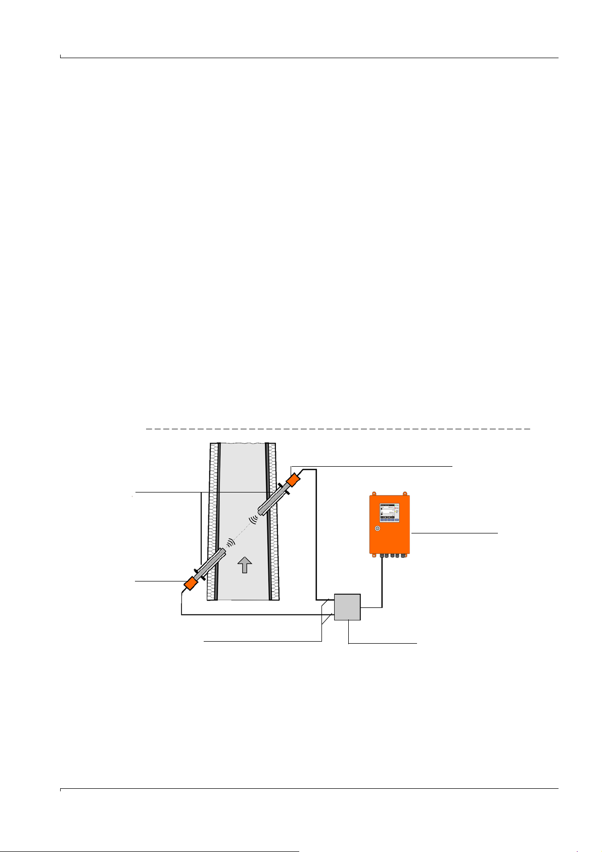
2.2 System overview and functional principle
2.2.1 System overview
The measuring system comprises the following components:
● FLSE100 sender/receiver unit
For transmitting and receiving ultrasonic pulses, signal processing and controlling the
system functions
● Flange with tube
For mounting the sender/receiver units on the gas duct
● MCU control unit
For control, evaluation and output of the data of the sensors connected via RS485
interface
● Connection cables
For signal transmission between the sender/receiver units and control unit
● Junction box for connection cable
For connecting the connection cables
● Purge air unit option
For using purged sender/receiver units to keep the ultrasonic transducers clean and
cool at high gas temperatures
● Cool air unit option
For using internal cooled sender/receiver units to keep the ultrasonic transducers cool
at high gas temperatures
● Measuring tube option
Tube piece with flanges, preassembled for installation in an existing pipeline; with
flanges with tube to fit the sender/receiver units
Subject to change w ithout notice
Fig. 1 FLOWSIC100 system components
● Cooling air control option for device types M-AC and H-AC
Used to control the cooling air supply for sender/receiver units with internal cooling by
switching the cooling air blower on and off automatically depending on the transducer
temperature.
● Emergency air supply option for sender/receiver units with internal cooling (FLSE100MAC and HAC)
Set for connecting and operating a temporary emergency air supply of instrument air (to
be provided by customer) for sender/receiver units with internal cooling.
● Emergency air supply option for externally purged sender/receiver units (FLSE100-PM,
PH, PH-S)
FLOWSIC100 · Operating Instructions · 8012513/YSA5/V 2-1/2016-07 · © SICK Engineering GmbH 13
Page 14
Set for connecting and operating a temporary emergency air supply of instrument air (to
Bus line
Junction box
be provided by customer) for externally purged sender/receiver units.
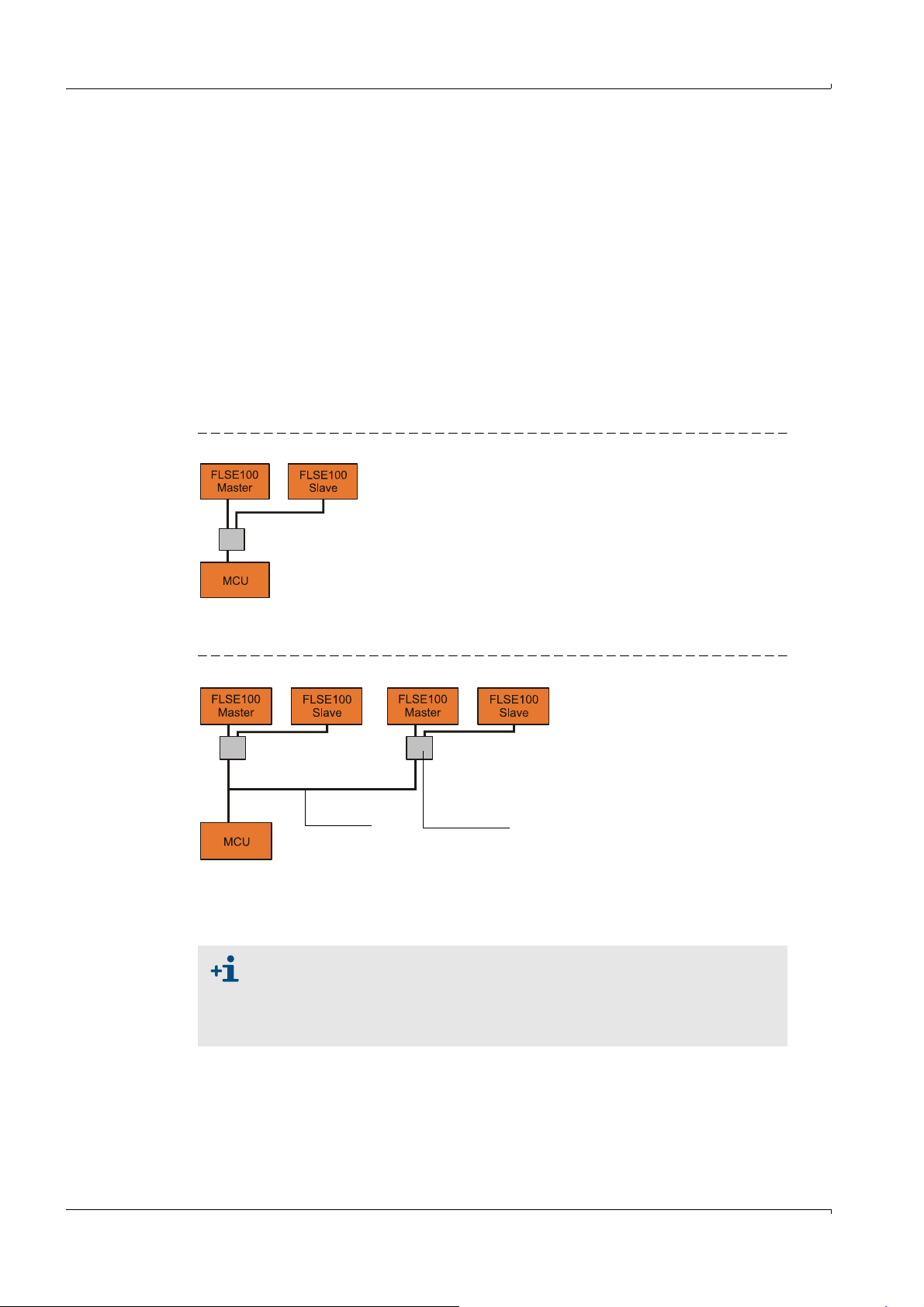
2.2.2 Communication between sender/receiver units and control unit
Standard version
The two sender/receiver units work as master and slave. The master FLSE has a second
interface to be able to completely separate communication to the slave FLSE and to the
MCU. The master triggers the slave and controls measurement. The MCU can request the
measured values from the master units independently of the measuring cycle
(asynchronous).
For the cabling, the junction box used to separate the interfaces has to be installed on the
master FLSE. The junction box is optional for FLOWSIC100 types PR and S (for longer cable
lengths).
Fig. 2 Standard version (1 sensor pair)
Product Description
Bus version with several measuring systems connected
Fig. 3 Bus connection FLSE100 - MCU (2 sensor pairs)
With the bus version, two autonomous measuring paths (2 x 2 FLSE100) can be connected
to a control unit MCU for 2-path-measurement. The MCU computes both measuring paths
to one measuring result.
● For bus wiring, the set termination set at the factory must be deactivated in
those system components not at the line end (see Service Manual Section
3.1).
● Other sensor types (e.g. sensor for dust measurement) can also be connected to the MCU.
14 FLOWSIC100 · Operating Instructions · 8012513/YSA5/V2-1/2016-07 · © SICK Engineering GmbH
Subject to change w ithout notice
Page 15
Product Description
Sender/receiver unit FLSE100 - Slave (B)
v = Gas flow rate in m/s
L= Measuring path in m
= Angle of inclination in °
t
v
= Signal transit time
in flow direction
t
r
= Signal transit time
against flow direction
Sender/receiver
unit
FLSE100 Master (A)
t
v
v
a
t
r
L
v = · ()
L 1 1
2 · cos tvt
r
tr =
L
c - v · cos
t
v
=
L
c + v · cos
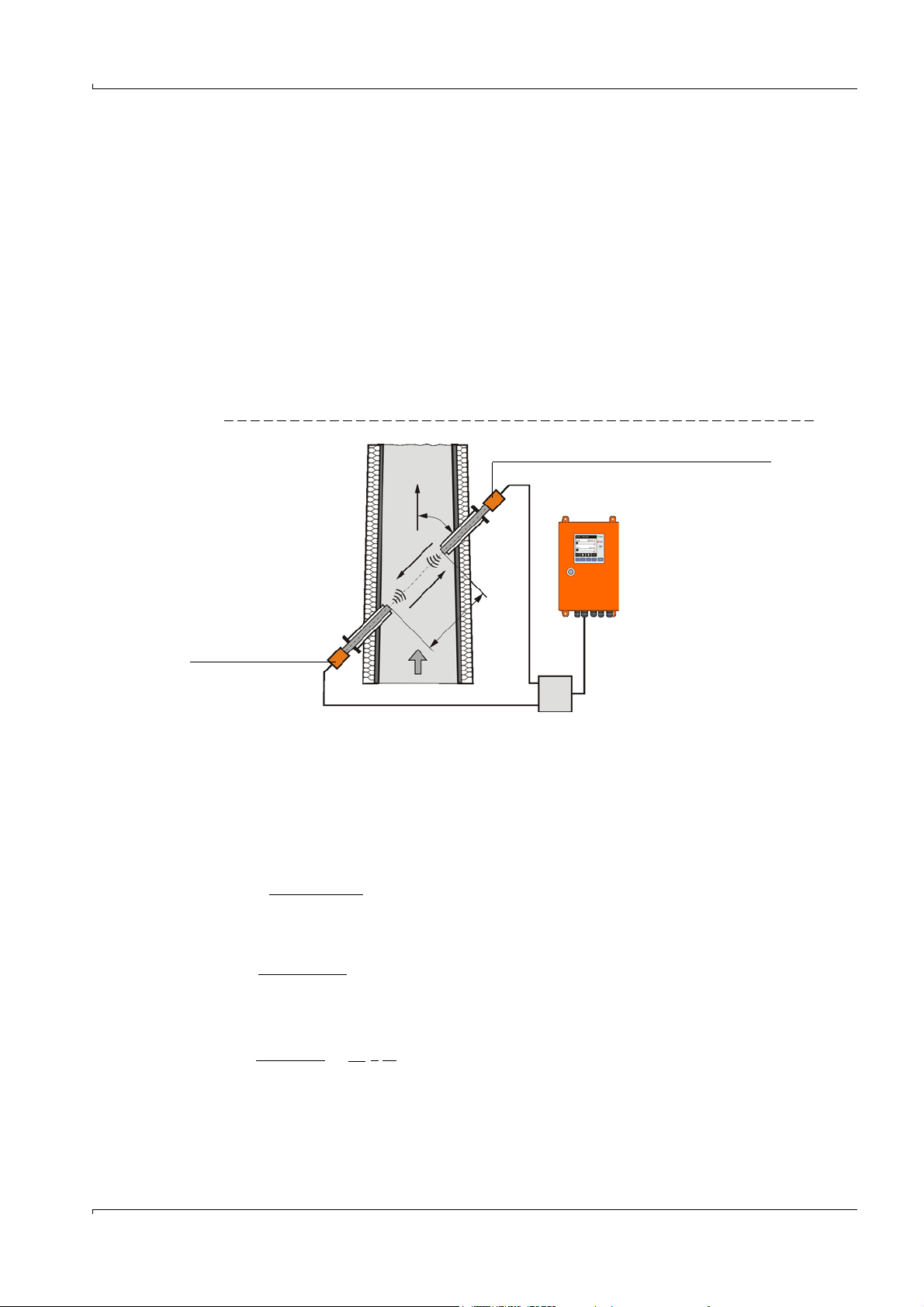
2.2.3 Functional principle
The FLOWSIC100 gas flow rate measuring devices operate according to the principle of
ultrasonic transit time difference measurement. Sender/receiver units are mounted on
both sides of a duct/pipeline at a certain angle to the gas flow (
These sender/receiver units contain piezoelectric ultrasonic transducers that function
alternately as senders and receivers. The sound pulses are emitted at an angle to the
flow direction of the gas. Depending on the angle and the gas flow rate v, the transit time
of the respective sound direction varies as a result of certain "acceleration and braking
effects" (formulas 2.1 and 2.2). The higher the gas flow rate and the smaller the angle to
the flow direction are, the higher the difference in the transit times of the sound pulses.
Gas flow rate v is calculated from the difference between both transit times, independent
of the sound velocity value. Therefore changes in the sound velocity caused by pressure or
temperature fluctuations do not affect the calculated gas flow rate with this method of
measurement.
Fig. 4 Functional principle of the FLOWSIC100
Fig. 4).
Subject to change w ithout notice
FLOWSIC100 · Operating Instructions · 8012513/YSA5/V 2-1/2016-07 · © SICK Engineering GmbH 15
Calculating the gas flow rate
Measuring path L is equal to the active measuring path, that is, the area through which the
gas flows. Given measuring path L, sound velocity c, and angle of inclination between the
sound and flow direction, the sound transit time in the direction of the gas flow (forward
direction) when the signal is transmitted can be expressed as:
(2.1)
Against the gas flow (backward direction):
(2.2)
After the resolution to v:
Apart from the two measured transit times, this relation only contains the active measuring
path and the angle of inclination as constants.
(2.3)
Page 16

Product Description
c = c0 ·
1 +
273 °C
= 273°C · ( () - 1)
4 · c
0
²
t
v
·
t
r
L
²
tv + t
r
²
c = · ()
L tv + t
r
2 tv ·t
r
Sound velocity
Sound velocity c can be calculated by resolving formulas 2.1 and
2.2.
(2.4)
Based on the dependencies in formulas 2.5 and 2.7, the sound velocity can be used to
determine the gas temperature and for diagnosis purposes.
(2.5)
Calculating the gas temperature
Since the sound velocity is dependent on the temperature, the gas temperature can also
be calculated from the transit times (by resolving formulas 2.4 and 2.5 to derive
).
(2.6)
Formula 2.6 shows that, in addition to the measured transit times, the square of the values
of L and the standard velocity are included in the calculation.
This means precise temperature measurement is only possible when the gas
composition is constant, measuring path L has been measured extremely
accurately and a calibration has been carried out (see Section
p. 151, 4.3.6).
Determining the volume flow
The volume flow in operating state is computed using the geometric constants of the duct.
The process parameters pressure, temperature and moisture content are required to
calculate the volume flow in the standard state. A detailed description is provided in
Section § 2.4, page 44.
Path compensation
When the FLOWSIC100 is operated with a 2-path configuration, the device runs with an
integrated algorithm for automatic "path compensation".
During trouble-free operation, gas and sound velocity relations between both measuring
paths are recorded and saved. Should one path then fail, the system can replace invalid
measured values from the failed path with theoretical values based on the "learned" path
relations. The system signals "Maintenance request" status at the same time.
This means a single path can be compensated temporarily and measurement continued
with a slightly higher uncertainty until the malfunction has been cleared.
16 FLOWSIC100 · Operating Instructions · 8012513/YSA5/V2-1/2016-07 · © SICK Engineering GmbH
Subject to change w ithout notice
Page 17
Product Description
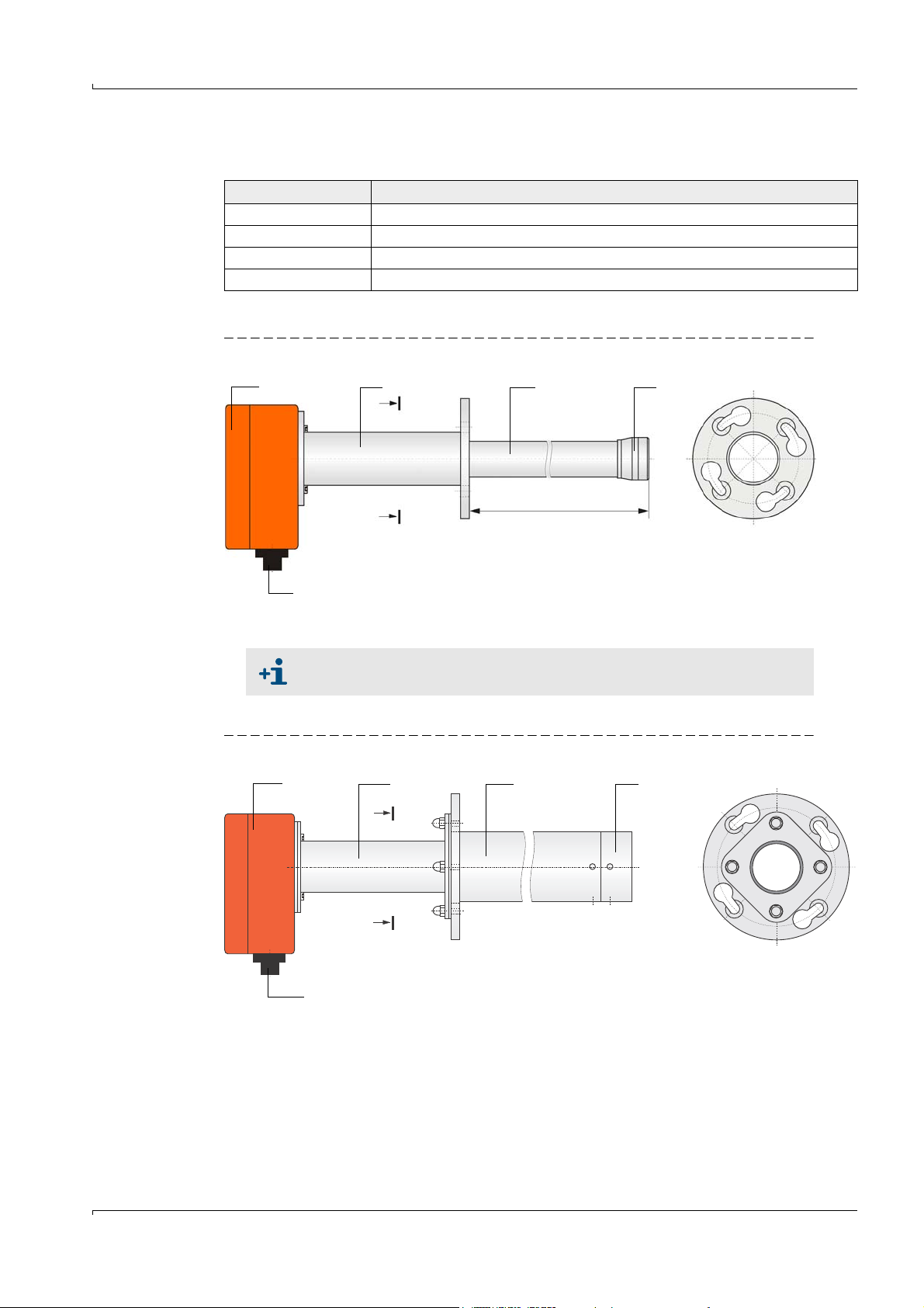
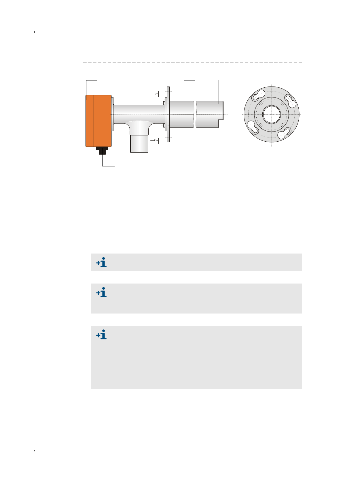
1
1 Electronics unit 4 Transducer
2 Connection piece 5 Flange with tube
3 Duct probe 6 Purge air connection (only for purged versions PM, PH, PHS)
Cooling air connection (only for internally cooled versions MAC, HAC)
2
34
5
6
2.3 System components
2.3.1 FLSE100 sender/receiver unit
The sender/receiver unit consists of the electronics, connector, duct probe, and transducer
modules. These modules are available in different versions that can be combined on the
basis of the relevant application data to produce the optimum configuration for the
application in question.
Fig. 5 Schematic diagram with modules of the sender/receiver unit and flange with tube
Subject to change w ithout notice
FLOWSIC100 · Operating Instructions · 8012513/YSA5/V 2-1/2016-07 · © SICK Engineering GmbH 17
Page 18

Product Description
The modules are selected on the basis of the following criteria:
● Gas temperature
Decide whether the sender/receiver unit must or can be used with or without internal
cooling air so that the duct probe can be selected with regard to type of material (steel,
titanium) and the transducer type (with/without internal cooling)
● Gas composition (corrosive / slightly corrosive or not corrosive)
The duct probe and transducers are selected on the basis of their resistance to corrosion (probe made from stainless steel / titanium, transducers made from titanium /
hastelloy)
● Duct diameter, sound dampening, dust content
The transducers are selected on the basis of the required transmitter power (medium
power / high power)
● Dust properties
Decide whether purged sender/receiver units need to be used (prevention of contamination with very sticky dust).
● Wall and insulation thickness of the gas duct
Selection of the duct probe and flange with tube according to the nominal length
(graded standard lengths). Other lengths can be supplied on request.
● Assembly type
On two sides, each with a sender/receiver unit on the opposite duct walls, or on one
side with one sender/receiver unit (as measuring probe version)
● Flange size
Small or large flange dimensions
(pitch diameter of the fixing holes 75 mm, 100 mm or 114 mm)
● Internal duct pressure
Pressure resistant versions must be used with pressures above 100 mbar (see OI
FLOWSIC100 PROCESS)
● Certification requirements
Selection after performance tests for emission measuring.
The various configuration options are identified by a type key structured as follows:
18 FLOWSIC100 · Operating Instructions · 8012513/YSA5/V2-1/2016-07 · © SICK Engineering GmbH
Subject to change w ithout notice
Page 19

Product Description
Type key sender/receiver unit: FLSE100-XXX (X) XX XX XX
Purge air supply yes/no
- P: Purged
Ultrasonic transducer
- M: Medium power
- H: High power
- S: Low power with small dimensions
(Small size)
- PR: Low power with small dimensions
and measuring probe version
Signal transmission
- D: Digital (identification for FLSE100-SD only)
- A: Analog (identification for FLSE100-SA only
- Empty: Digital
Identification
- Empty: No special features
- AC: Internal cooling of ultrasonic transducer
Nominal length of duct probe
- 12: 125 mm
- 20: 200 mm
- 35: 350 mm
- 55: 550 mm
- 75: 750 mm
Duct probe material
- SS: 1.4571 (stainless steel)
- TI: Titanium
- HS: Hastelloy
Transducer material
- TI: Titanium
- HS: Hastelloy
Example: FLSE100-M 35SSTI
Medium transducer power
Duct probe nominal length 350 mm
Duct probe material 1.4571
Transducer made of titanium
The possible versions, areas of application, configurations, and characteristics are listed in
the following Tables.
Subject to change w ithout notice
FLOWSIC100 · Operating Instructions · 8012513/YSA5/V 2-1/2016-07 · © SICK Engineering GmbH 19
Page 20
Basic versions
Typ e F LSE10 0 Description
M
● Not purged
● Medium power
● Digital signal transmission to control unit
Product Description
Number of
FLSE100 per
system
2
H
● Not purged
● High power
● Digital signal transmission to control unit
PR ● Not purged
● With two transducers, small size and high frequency
● Version as measuring probe for installation on one duct
side
● Digital signal transmission to control unit
SA/SD
● Not purged
● With one small size and high frequency transducer
● Digital signal transmission to control unit (SD)
MAC ● Air cooled (internal)
● Medium power
● Digital signal transmission to control unit
HAC
● Air cooled (internal)
● High power
● Digital signal transmission to control unit
2
1
1 each
2
2
PM
● Purged
● Medium power
2
PH
● Digital signal transmission to control unit
● Purged
● High power
2
PHS
● Digital signal transmission to control unit
● Purged
● Very high power
● Digital signal transmission to control unit
20 FLOWSIC100 · Operating Instructions · 8012513/YSA5/V2-1/2016-07 · © SICK Engineering GmbH
2
Subject to change w ithout notice
Page 21
Product Description
Application range
Type FLSE100
M
H
Material
Duct probe
SS, TI TI
Hastelloy 0.2 - 2 0.15 - 1.7
SS, TI TI
Material
Tra nsdu cer
Max. gas
temperature
[°C]
260
Active meas.
distance
1)
[m]
Duct/pipe
diameter [m]
0.2 - 4 0.15 - 3.4
2 - 15 1.4 - 13
1.5 - 2.5
2)
1.1 - 2.5
Hastelloy 2 - 5 1.4 - 4.3
PR
SA/SD
MAC
HAC
PM
PH
PHS
SS, TI
0.27 - 0.28 > 0.40
SS 150 0.2 - 2 0.15 - 1.7
0.2 - 4 0.15 - 3.4
SS, TI 450
SS
SS, TI
Tl
450
SS
2 - 13 1.4 - 11.3
1.5 - 2.5
2)
1.1 - 2.5
0.5 - 3 0.35 - 2.5
1 - 10 0.7 - 8.7
2)
1 - 2
0.7 - 2
2 - 13 1.4 - 11.3
1.5 - 2.5
2)
1.1 - 2.5
1): The maximum possible measuring path depends on the dust content, gas temperature,
and gas composition
2): For extremely high dust concentrations up to max. 100 g/m³
3): For installation across secant (
p. 57, 3.1.3)
3)
3)
3)
3)
Subject to change w ithout notice
FLOWSIC100 · Operating Instructions · 8012513/YSA5/V 2-1/2016-07 · © SICK Engineering GmbH 21
Page 22
Duct probe configuration options
Type FLSE100
Nominal length in mm Material
125 200 350 550 750 SS TI HS
M xxx xxx
H xxxxxxx
PR xxxxx
SA/SD xxx x
MAC x x x x
HAC x x x x
PM xxxxx
PH xxxxxx
PHS x x x x
2.3.1.1 Standard sender/receiver units
A special transducer design makes it possible to use these sender/receiver units without
cooling by external purge air even with higher gas temperatures. A purge air unit is
therefore not necessary. The advantages are:
● Lower expense for mounting and installation
● Easier maintenance
● Lower operating costs.
For these reasons, standard sender/receiver units should be used where possible.
Product Description
Duct probe
● The types FLSE100-M, H and PR are intended for use with gas
temperatures up to max. 260
°C. The types FLSE100-SA and SD are
intended for use up to 150°C.
● The measuring system FLOWSIC100 S contains one sender/receiver
unit FLSE100-SA and FLSE100-SD and one connection cable between
the sender/receiver units.
● The type FLSE100-SA has no electronics unit. Communication to the
FLSE100-SD as master (which communicates with the MCU control
unit) runs via an analog connection cable (fixed length: 3m). Install one
FLSE100-SA and one FLSE100-SD per sampling point (1-path configuration).
● Fit the sender/receiver units at an angle of 60° to the flow direction for
dust concentrations > 1 g/m³ (only applicable for FLSE100-H, H-AC, PH
and PH-S). The downstream sender/receiver unit (B in
p. 15, Fig. 4) has
to be equipped with an impact protector.
Subject to change w ithout notice
22 FLOWSIC100 · Operating Instructions · 8012513/YSA5/V2-1/2016-07 · © SICK Engineering GmbH
Page 23
Product Description
NL = 200 mm, 350 mm, 550 mm
NL
A
A
A - A
1 Electronics unit 4 Transducer
2 Connection piece 5 Connection for connection cable
3 Duct probe
1
2
34
5
A - A
NL = 200 mm, 350 mm, 550 mm, 750 mm
A
A
NL
1
2
34
5
1 Electronics unit 4 Transducer
2 Connection piece 5 Connection for connection cable
3 Duct probe
Fig. 6 FLSE100-M
The following differences exist in addition to the possible versions:
Type FLSE Transducer and duct probe
M Nominal diameter 35 mm
H Nominal diameter 60 mm
PR Measuring probe version (2 transducers)
SA, SD Duct probe Ø 35 mm, transducer 15 mm
The type FLSE100-M is also available with other flanges on request (p.
169, 6.3.1).
Fig. 7 FLSE100-H
Subject to change w ithout notice
FLOWSIC100 · Operating Instructions · 8012513/YSA5/V 2-1/2016-07 · © SICK Engineering GmbH 23
Page 24
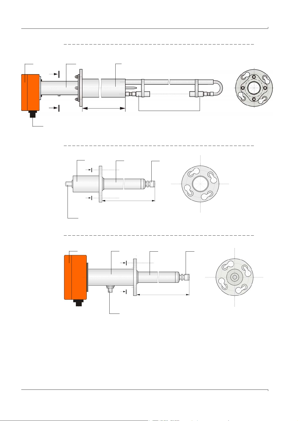
Fig. 8 FLSE100-PR
A - A
NL = 350 mm, 550 mm, 750 mm
A
A
NL
1
2
3
4
5
A
A
NL
A - A
NL = 125 mm, 200 mm, 350 mm
2
3
4
5
NL
A
A
A - A
NL = 125 mm, 200 mm, 350 mm
1 Electronics unit 4 Transducer
2 Connection piece 5 Connection for connection cable
3 Duct probe
1
2
4
5
3
Fig. 9 FLSE100-SA
Product Description
Fig. 10 FLSE100-SD
Subject to change w ithout notice
24 FLOWSIC100 · Operating Instructions · 8012513/YSA5/V2-1/2016-07 · © SICK Engineering GmbH
Page 25
Product Description
A - A
NL =350 mm, 550 mm
A
A
NL
6
1
2
4
3
5
1 Electronics unit 4 Transducer
2 Connection piece 5 Connection for connection cable
3 Duct probe 6 Cooling air connection
2.3.1.2 Sender/receiver units with internal cooling
The types FLSE100-MAC and HAC can be used for gas temperatures up to maximum
450°C when fitted with internal cooling for the ultrasonic transducers. A control unit with
integrated filter and blower supplies the cooling air (
The advantages over the purged versions are:
● Lower costs for installation and operation.
● No flow of cooling air into the measured medium, therefore no direct influence on gas
flow and flow rate.
● Lower risk of dropping below the dew point with condensate on the probe head.
Fit the sender/receiver units at an angle of 60° to the flow direction for dust
concentrations > 1 g/m³ (only applicable for FLSE100-HAC). The downstream sender/receiver unit (B in Fig. 4, page 15) must be equipped with an
impact protector.
NOTICE:
Wet or sticky dust can cause strong contamination of the transducer and
disrupt the measuring function. In this case, the cooling air control option, Part
No. 2050814, should be used on device versions with internal cooling (M-AC
and H-AC). Use an external device version when necessary.
p. 29, 2.3.3).
The following differences exist in addition to the possible versions:
Type FLSE100 Transducer and duct probe
MAC Nominal diameter 35 mm
HAC Nominal diameter 60 mm
Fig. 11 FLSE100-MAC
The type FLSE100-MAC is also available with other flanges on request (p.
Subject to change w ithout notice
FLOWSIC100 · Operating Instructions · 8012513/YSA5/V 2-1/2016-07 · © SICK Engineering GmbH 25
169, 6.3.1).
Page 26
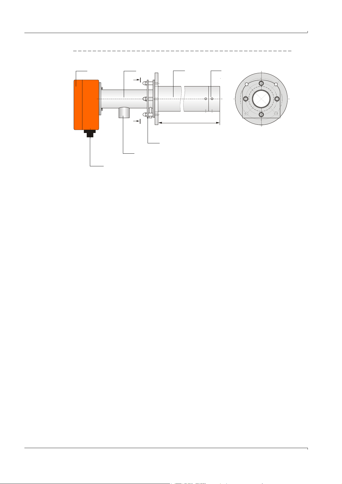
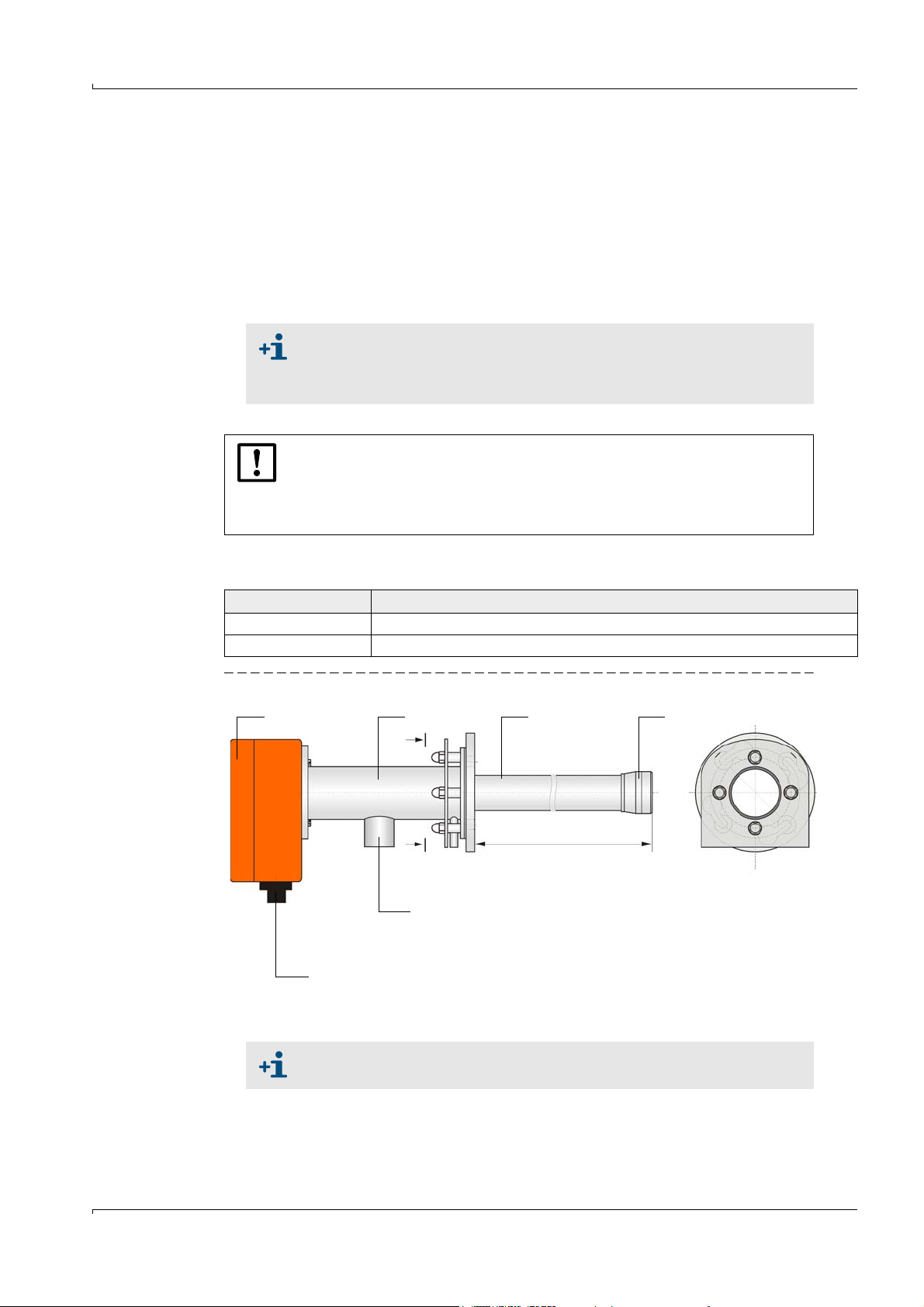
Fig. 12 FLSE100-HAC
NL =350 mm, 550 mm
A
A
NL
1 Electronics unit 5 Connection for connection cable
2 Connection piece 6 Cooling air connection
3 Duct probe 7 Guard plate
4 Transducer
6
7
1
2
4
3
5
A -
Product Description
26 FLOWSIC100 · Operating Instructions · 8012513/YSA5/V2-1/2016-07 · © SICK Engineering GmbH
Subject to change w ithout notice
Page 27
Product Description
NL = 200 mm (only PM and PH)
350 mm
550 mm
750 mm
NL
A
A
1 Electronics unit 4 Transducer
2 Connection piece 5 Connection for connection cable
3 Duct probe
1
2
4
3
5
A -
2.3.1.3 Purged sender/receiver units
Fig. 13 FLSE100-PM, PH, PHS
These sender/receiver units are intended only for use with wet and sticky dust when the
transducer surface is in high danger of contamination. Purge air is supplied by a purge air
unit to keep the active transducer surface clean and therefore protect against
contamination (
p. 43, 2.3.9). The purge air flow is optimized to maximize the directivity of
the ultrasound beam.
An integrated temperature sensor records the transducer temperature which can then be
displayed in SOPAS ET.
See the Application Range Table on page 21 for limitations of use
For dust concentrations > 1 g/m³, install the sender/receiver units at an
angle of 60° to the flow direction (only applicable for FLSE100-PH and
PHS). The downstream sender/receiver unit (B in
p. 15, Fig. 4) has to be
equipped with an impact protector.
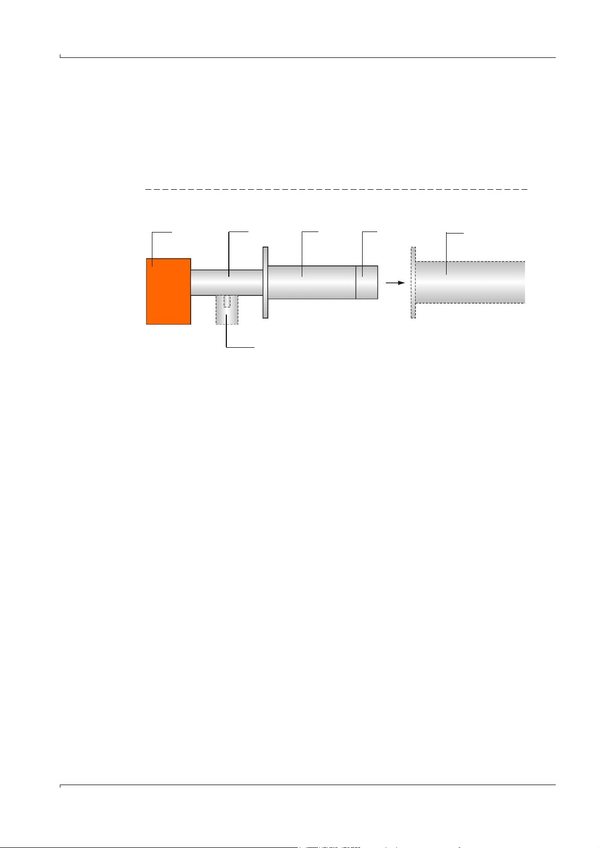
At low gas temperatures, the purge air supply can cause the temperature to
drop below the dew point. To minimize the possible corrosion on the probe
head (for example, due to acid formation with corrosive gas compositions),
duct probes with a nominal length greater than that actually required for
the flanges with tube must be selected for temperatures between 150
and 200
350 mm
°C (for example, if the nominal length of the flange with tube is
a duct probe with a nominal length of 550 mm should be
°C
used). The purge air is then heated by the gas temperature in the probe
tube which minimizes temperature drops below the dew point.
Subject to change w ithout notice
FLOWSIC100 · Operating Instructions · 8012513/YSA5/V 2-1/2016-07 · © SICK Engineering GmbH 27
Page 28
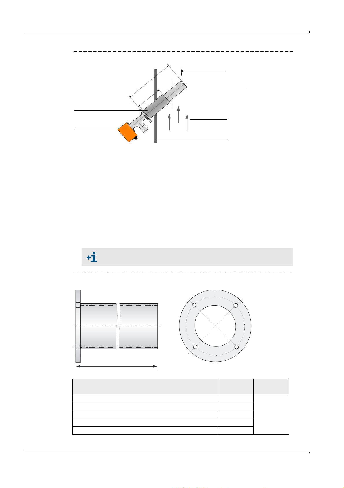
Fig. 14 Using sender/receiver units with a nominal length greater than the flange with tube
Flange with tube
Sender/receiver
unit
Purge air
Area heated by
the gas flow
Gas flow
Duct wall
N
L
F
L
S
E
1
0
0
N
L
F
NL
FLSE100
= Nominal length sender/receiver unit
NL
F
= Nominal length flange with tube
L
L = NL - 12
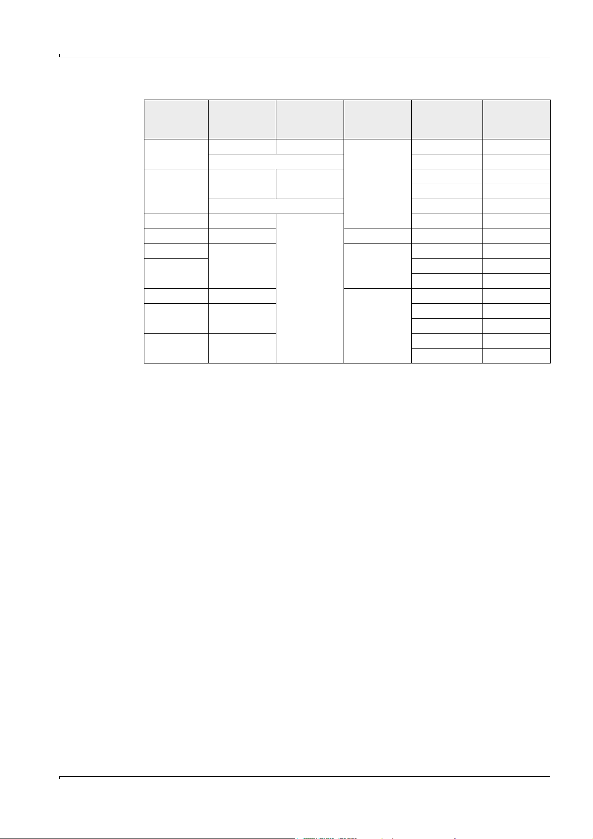
Type FLSE100 Nominal
length in mm
Material
S 125
St37, V4A
(others on
request)
S, M, PM, PH 200
S, M, MAC, H, HAC, PR, PM, PH, PHS 350
M, MAC, H, HAC, PR, PM, PH, PHS, 550
H, PR, PM, PH, PHS 750
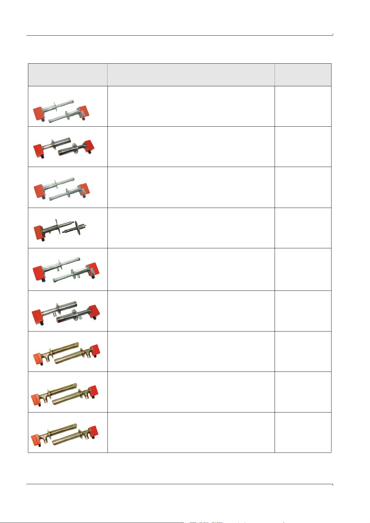
2.3.2 Flange with tube
The sender/receiver units are mounted in flanges with tube available in graded nominal
lengths, different steel types and pitch diameters.
Selection of a flange with tube depends on:
● Installation angle and wall and insulation thickness of duct wall
Determining the nominal length (Assembly and Installation Chapter,
● Type of sender/receiver unit
Pitch diameter of flange, pipe diameter
● Duct material
Steel type
Product Description
p. 49)
If required, the flanges with tube can also be delivered in advance.
Fig. 15 Flange with tube
28 FLOWSIC100 · Operating Instructions · 8012513/YSA5/V2-1/2016-07 · © SICK Engineering GmbH
Subject to change w ithout notice
Page 29
Product Description
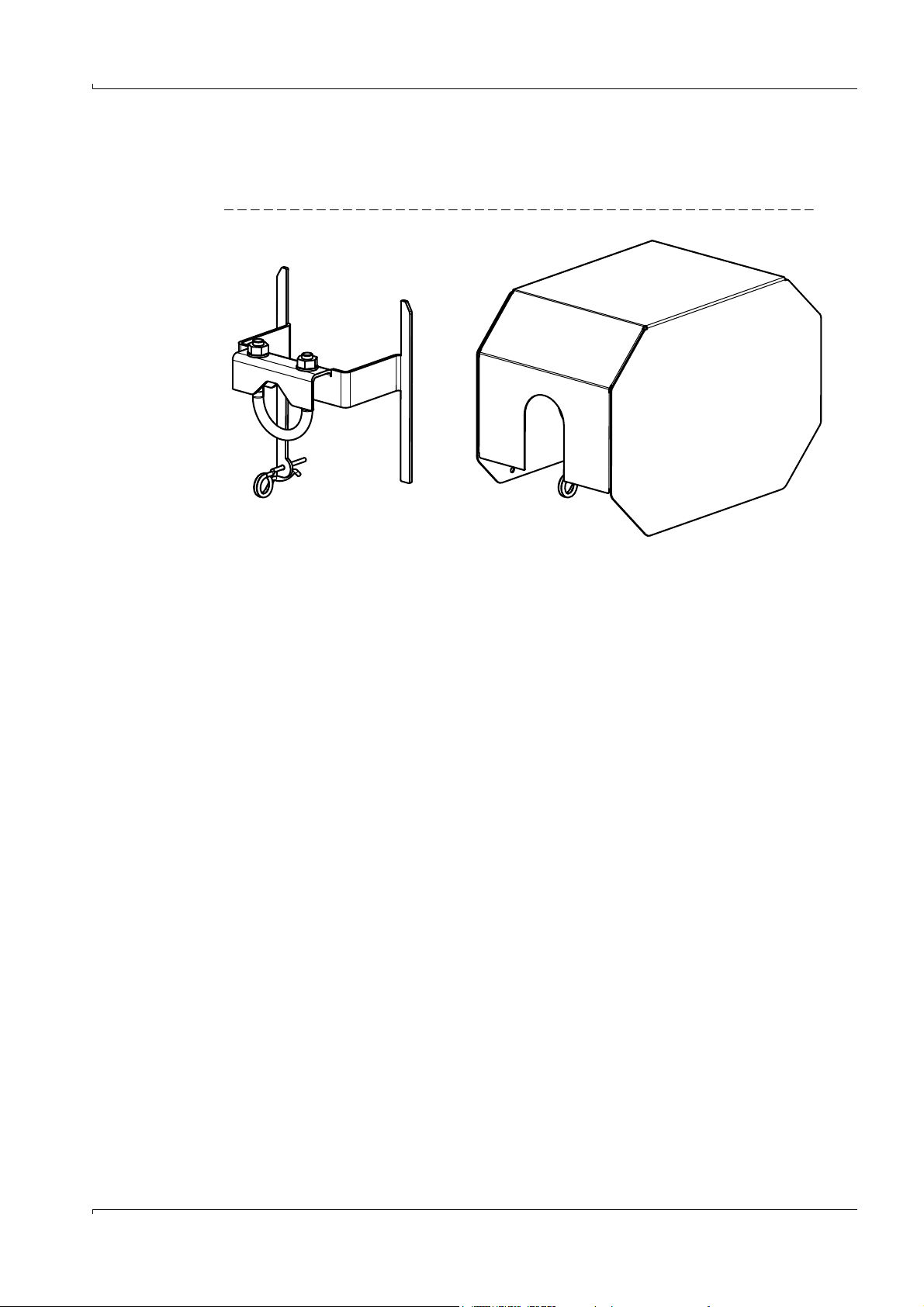
2.3.3 Weatherproof cover
The weatherproof cover protects the electronics of the sender/receiver unit against
sunlight and rain.
Fig. 16 Weather protection with holder
2.3.4 MCU control unit
The control unit has the following functions:
● Control of data transfer and processing the data from the sender/receiver units
connected via RS485 interface
● Signal output via analog outputs (measured value) and relay outputs (device status)
● Signal input via analog and digital inputs
● Voltage supply for the connected sender/receiver units
● Communication with host control systems via optional modules
System and device parameters can be set easily and conveniently via a USB interface
using a laptop and the user-friendly SOPAS ET operating software. The parameters are
stored reliably even in the case of a power failure.
The control unit is usually installed in a steel plate housing. It is available as 19" rack as an
option.
Subject to change w ithout notice
FLOWSIC100 · Operating Instructions · 8012513/YSA5/V 2-1/2016-07 · © SICK Engineering GmbH 29
Page 30
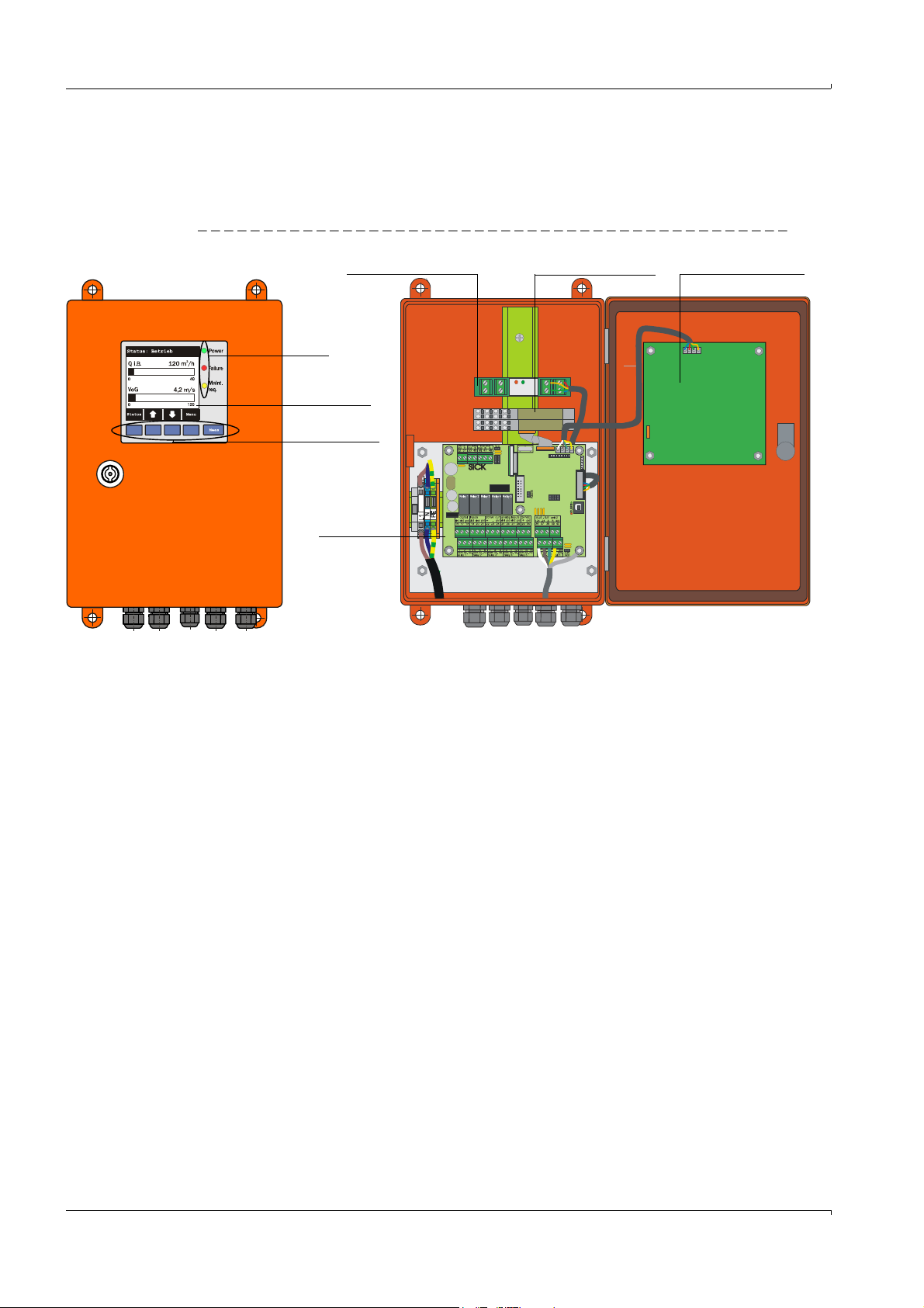
Versions
LED
LC-Display
option
Control buttons
Connection
board
Interface module option
I/O module option
Display module option
1 Control unit without cooling air supply
This control unit serves for connecting sender/receiver units FLSE100-M, H, PR, S, PM,
PH and PHS (optional for FLSE100-MAC and HAC).
Fig. 17 Control unit MCU with options
Product Description
2 Control unit with integrated cooling air supply (only for types M-AC and H-AC)
This version is additionally equipped with a purge air blower, air filter and purge air connection for connecting DN 25 purge air hoses (must be ordered separately
p. 171,
Fig. 138) for sender/receiver units with internal cooling (types FLSE100-MAC and HAC).
Subject to change w ithout notice
30 FLOWSIC100 · Operating Instructions · 8012513/YSA5/V2-1/2016-07 · © SICK Engineering GmbH
Page 31

Product Description
Purge air connection
Power supply unit (on back of installation plate)
Purge air inlet
Processor board
Option
LC-Display
Air filter
Purge air blower
Installation plate
Fig. 18 Control unit with integrated cooling air supply
Standard interfaces
Analog output Analog inputs Relay outputs Digital inputs Communication
1 output 0/2/4 ... 22 mA
(active) for selectable output of measured variables:
● Velocity
● Volume flow act.
● Volume flow std.
● Temperature
● Resolution 12
Subject to change w ithout notice
2 inputs 0 ... 20 mA
(standard; without
electric isolation) or
0 ... 5/10 V for selectable
input of optional entry of
calculation variables
(temperature, pressure,
moisture) resolution
12 bit
5 changeover contacts
(48 V 1 A) to output
status signals:
● Operation/malfunction
● Maintenance
● Check cycle
● Warning
● Limit value
2 inputs for connecting
potential-free contacts
(e.g. for connecting a
maintenance switch or
triggering a check cycle)
● USB 1.1 and RS232
(on terminals) for
measured value
inquiries, setting
parameters and firmware updates
● RS485 to connect
sensors
FLOWSIC100 · Operating Instructions · 8012513/YSA5/V 2-1/2016-07 · © SICK Engineering GmbH 31
Page 32

Control unit MCU in 19” enclosure with options
SICK
M
ULTI CONTROL UNIT
POWER
FAILURE
MAINTENANCE
REQUEST
INTERFACE-MODULE
I/O-MODULE
POWER
ERROR
TxD RxD
Slots for optional I/O modules
Backplane with terminal connections for wiring by customer
Power
Slot for interface module option
Display module option
Product Description
32 FLOWSIC100 · Operating Instructions · 8012513/YSA5/V2-1/2016-07 · © SICK Engineering GmbH
Subject to change w ithout notice
Page 33

Product Description
MCU
Relay 5
Relay 4
Relay 3
Relay 2
Relay 1
Processor
Optional I/O module(s)
Display module option
Interface module option
RS232
USB 1.1
Analog
inputs
1 and 2
Analog
output
Digital
inputs
1 to 4
Wide-range
power pack
Relays
1 to 5
90 ... 250 V AC
Block Diagram
Fig. 19 MCU block circuit diagram
Subject to change w ithout notice
FLOWSIC100 · Operating Instructions · 8012513/YSA5/V 2-1/2016-07 · © SICK Engineering GmbH 33
Page 34

Product Description
Options
Using the following options, the functionality of the MCU can be extended considerably:
1 Display module
Module to display measured values and status information of the connected sensors
using control buttons (capacitive sensors). The integration of this module into already
delivered control units can only be done by the supplier.
Displays
Typ e Display
Power (green) Voltage supply OK
LED
Failure (red) Functional failure
Maint. request (yellow) Maintenance request
Two of a variety of possible measured values:
Volume flow in operating state (Q a.c.)
Volume flow in standard state (Q std.)
Gas flow rate (VoG)
LC-Display
Graphical display
(main display)
Sound velocity (SoS)
Acoustic temperature (T ac)
Transducer temperature A (T A)
Transducer temperature B (T B)
Signal to noise ratio A (SNR A)
Signal to noise ratio B (SNR B)
Mass flow
Text display 6 possible measured values (see graphical display)
The measurement screen displays bar graphs of two selectable main measured values
of a connected sensor or of the MCU. Alternatively, up to 8 individual measured values
of a sensor can be displayed (switching with button “Meas”).
Fig. 20 LC-Display in graphical display (left) and in text display (right)
If a limit value is exceeded, the display alternates between the measured value and an
alarm message.
Subject to change w ithout notice
34 FLOWSIC100 · Operating Instructions · 8012513/YSA5/V2-1/2016-07 · © SICK Engineering GmbH
Page 35

Product Description
Control buttons
Button Function
● Selects the single measured value to be displayed
Meas
● Toggles between text display and graphical display
● Displays the contrast settings (after 2.5 s)
Arrows ● Selects next/previous measured value screen
Status ● Displays alarm or error messages
Menu ● Display of main menu
The following functions are additionally available in the display module:
–Entering parameters for start-up
– Initiating a check cycle
– Switching to Maintenance mode.
2 I/O module
For installation on module carriers, communication via I²C bus, or in rack (MCU in 19”
enclosure), selectable as:
– 2x analog output 0/4 ... 22 mA to output further measured variables (load 500
– 2x analog input 0/4 ... 22 mA to read in values from external sensors
)
● One module carrier is necessary for each module (to insert on top
hat rail). One module carrier has to be connected to the processor
board with a special cable, other module carriers can be docked to
it.
● Maximum for installation and use:
–2 optional AO modules
–1 optional AI module
3 Interface module
Modules to pass measured values, system status and service information to higher
level control systems, optional for Profibus DP, Ethernet and Modbus, for insertion in
slot (
p. 36, Fig. 21).
Profibus DP-V0 for transfers via RS485 according to DIN 19245 Part 3 as
well as IEC 6115
Subject to change w ithout notice
FLOWSIC100 · Operating Instructions · 8012513/YSA5/V 2-1/2016-07 · © SICK Engineering GmbH 35
Page 36

MCU processor board connections
12 34
98
10
11
12
5
6
7
1 Supply voltage 24 V DC
2RS232
3 Connection for I/O module
option
4 Connection for display module
5 Connection for LEDs
6 Connection for interface
module option
7 USB plug-in connector
8 Connections for sender/
receiver units
9 Connections for relays 1 to 5
10 Connections for analog inputs 1
and 2
11 Connection for analog output
12 Connections for digital inputs 1
to 4 (digital inputs 3 and 4 not
supported at present)
Fig. 21 MCU processor board connections
Product Description
36 FLOWSIC100 · Operating Instructions · 8012513/YSA5/V2-1/2016-07 · © SICK Engineering GmbH
Subject to change w ithout notice
Page 37

Product Description
Control unit type key: MCU-X X X X X X X X X X X X X X
Integrated cooling air supply
- N: Without blower
- P: With blower
- C: Without blower + cooling air control option 24 V
- D: Without blower + cooling air control option 230 V
- E: With blower + cooling air control 24 V
Voltage supply
- W: 90 ... 250 V AC
- 2: Optional 24 V DC
Housing variant
- O: Wall enclosure compact, painted SICK orange,
stainless steel 1.4016 or equivalent
- R: 19“- housing
Display module
- N: Without
- D: With
Other options
- N: Without
Analog input option (plug-in module; 0/4...20 mA; 2 inputs per module)
- 0: Without
- n: With, n = 1. 2 2)
Analog output option (plug-in module; 0/4...22 mA; 2 outputs per module)
- 0: Without
- n: With, n = 1. 2 2)
Digital input option (plug-in module; 4 inputsper module)
- 0: Without
- n: Number on request
Digital output power option (plug-in module; 48 V DC, 5 A; 2 changeover contacts
per module)
- 0: Without
- n: Number on request
Digital output low power option (plug-in module; 48 V DC, 0.5 A; 4 NO contacts
per module)
- 0: Without
- n: Number on request
Optional Interface module
- N: Without
- B: T/P-MOD Ethernet V1,COLA-B, pulse 3)
- V: T/P-MOD Ethernet V1, COLA-B, 3-fold, pulse 3)
- Q: T/P-MOD Ethernet V2,MODBUS TCP, pulse 3)
- D: T/P-MOD RS485,MODBUS ASCII/RTU, pulse 3)
- F: T/P-MOD RS485,PROFIBUS, pulse 3)
Special features
- N: Without special version
Ex certification
- N: Without Ex certification
Typ e key MCU
The various configuration options are defined by the following type key:
Subject to change w ithout notice
FLOWSIC100 · Operating Instructions · 8012513/YSA5/V 2-1/2016-07 · © SICK Engineering GmbH 37
Page 38

Product Description
Software
- E: Emission
2): Up to 4 analog modules on request
3): Pulse not available
Example: MCU-NWODN01000PNNE
Without cooling air suppy
Wide-range power pack 90…250V AC
Wall enclosure SICK orange
With display module
Without other options
Without optional analog input module
With one optional analog output module
Without optional digital input module
Without optional digital output module, 2 changeover contacts
Without optional digital output module, 4 NO contacts
With optional interface module Profibus DP
Without special version
Without Ex certification
Software Emission
38 FLOWSIC100 · Operating Instructions · 8012513/YSA5/V2-1/2016-07 · © SICK Engineering GmbH
Subject to change w ithout notice
Page 39

Product Description
Onsite cable
Standard cables
Master (lengths 5 m, 10 m, 50 m)
Slave (5 m, 10 m, 50 m)
FLSE100 Master (A)
FLSE100 Slave (B)
Connection cable, Master
(Li2YCYv(TP) 3x2x0.5 mm²)
Connection cable, Slave
(Li2YCYv(TP) 2x2x0.5 mm²)
2.3.5 Connection cable
The connection cables master (Master FLSE100) and slave (Slave FLSE100) are used to
connect the sender/receiver units with the control unit MCU. Both cables are available in
different lengths. The connection cable master is marked with a red marker behind the
cable box.
Fig. 22 Connection cable
Cables provided onsite must fulfill the following requirements (see also
page 97, § 3.3.6):
● Lead/lead operational capacity less than 110 pF/m
● Min. lead cross-section 0.5 mm
We recommend cable type UNITRONIC Li2YCYv(TP) 2x2x0.5 mm
2
(AWG20).
2
with reinforced outer
sheath (from Lappkabel).
The total length of the cable between junction box and MCU (onsite cable) can be up to
1000 m.
When connecting bus versions with several sensors (p. 14, Fig. 3), the maximum cable length is reduced as follows depending on the number of sam-
Subject to change w ithout notice
pling points connected:
● Cable length with + 1 sampling point = 1000 m
● Cable length with + 2 sampling points = 500 m
FLOWSIC100 · Operating Instructions · 8012513/YSA5/V 2-1/2016-07 · © SICK Engineering GmbH 39
Page 40

2.3.6 Purge air unit option
Air filter
Blower
Base plate
Purge air hose
The purge air unit is used to supply the sender/receiver units of the types FLSE100-PM, PH
and PHS with clean purged air.
Fig. 23 Purge air unit SLV 1
Depending on the internal duct pressure, use additional reducers
(optional purge air reducer set) or a purge air unit with a more powerful blower as shown in
the following Table.
Product Description
Internal duct pressure (mbar) Reducer Blower type
-100 ... -20 40/7
2BH1300-20 ... -10 40/10
-10 ... +30 -
+30 ... +100 - 2BH1400
40 FLOWSIC100 · Operating Instructions · 8012513/YSA5/V2-1/2016-07 · © SICK Engineering GmbH
Subject to change w ithout notice
Page 41

Product Description
2.3.7 Cooling air control option for device types M-AC and H-AC
The "Cooling air control for device types M-AC and H-AC" subassembly serves minimizing
the number of temperature drops below the dewpoint on the ultrasonic transducer. The
cooling air blower is switched on or off depending on the transducer temperature. Cooling
therefore only runs for appropriately high gas or transducer temperatures. This prevents
permanent cooling air operation overcooling the probe. Setting the required limit values for
switching the cooling air supply on and off is made in SOPAS ET (
2.3.8 Optional sets for emergency air supply for device types with purge and cooling air
p. 150, 4.3.5).
operation
The optional sets for emergency air supply serve preventing severe damage to transducers
should the purge/cooling air supply fail. The sets are usable as described in the respective
written versions for the FLOWSIC100 measuring system with 1-path configuration, SOPAS
application setting "FLOWSIC100". The emergency air supply systems monitor failures in
supply voltage for the purge air blower. Prerequisite for using the sets for emergency air
supply is the on-site provision of compressed air free from oil and dust.
WARNING:
The emergency air supply systems only provide temporary protection for transducers against overheating (several hours) and must never be used as alternatives for standard purge/cooling air supply because there is a risk that the
emergency air supply systems create interfering noise on the transducers and
therefore influence measurement. On devices purged externally (FL100 PM,
PH and
PH-S), there is also a risk of the emergency air not keeping transducer surfaces
sufficiently clean.
Subject to change w ithout notice
FLOWSIC100 · Operating Instructions · 8012513/YSA5/V 2-1/2016-07 · © SICK Engineering GmbH 41
Page 42

2.3.8.1 Emergency air supply for device types M-AC and H-AC
Prerequisites:
1 Compressed air free from oil, dust and water provided by the customer.
2 Compressed air requirement about 9…11 m3/h
3 Primary pressure at least 1.5 bar (measurable with emergency air in operation).
Product Description
Cooling function during normal device operation (
p. 87, 3.3.4.1)
In normal operation, cooling air for sender/receiver units is supplied via the MCU blower
unit or, optionally, via a blower unit in a separate enclosure (
p. 180, Fig. 147).
Air path in normal operation (cooling air supply via MCU blower unit):
- Air entry in the MCU suction opening - air filter - blower unit - flexible DN25 hoses backflow valve - cooling air inlet S/R unit - cooling air discharges from S/R unit (after
deflection in probe tube).
The "backflow valve" is open in forward direction (rubber poppet valve).
Cooling function in emergency operation (cooling air failure due to interruption or
failure of the voltage supply to the cooling air blower)
An installed solenoid valve releases a flow of compressed air should the standard cooling
air fail. If the compressed air flow is pressurized, the emergency air valve (
p. 87, Fig. 57)
with integrated backflow valve closes in the blocking direction and the compressed air
flows into the cooling channels of both S/R units (
p. 87, Fig. 57).
42 FLOWSIC100 · Operating Instructions · 8012513/YSA5/V2-1/2016-07 · © SICK Engineering GmbH
Subject to change w ithout notice
Page 43

Product Description
Fitting on
both sides
Tube and flanges
made of St37 or
1.4571 (other materials on request)
L = 5 x DN
for DN 150
to DN 200
L = 3 x DN
for DN > 200
to DN 500
Flange according to
DIN 2573
Fitting on one
side
A
A
A
A
L
A - A
A - A
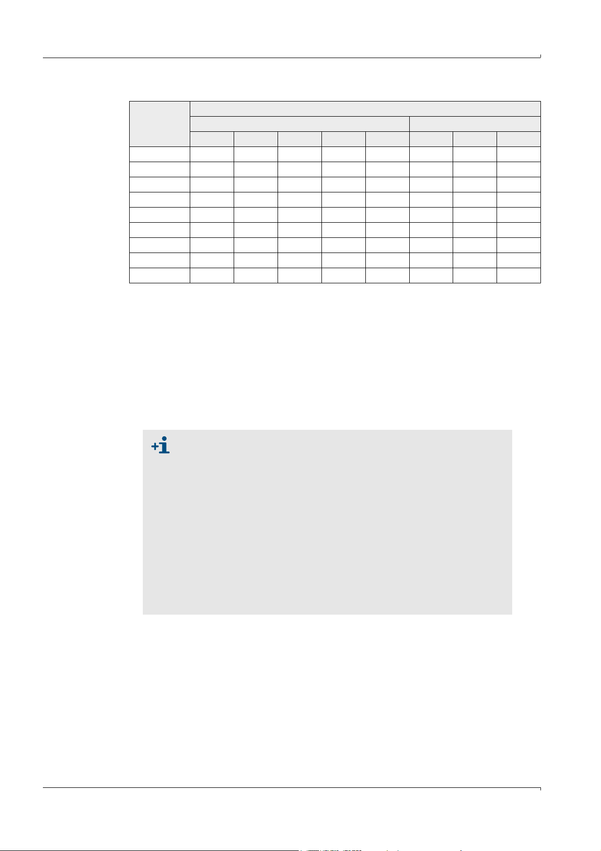
2.3.8.2 Emergency air supply for device types PM, PH and PH-S
Prerequisites:
1 Compressed air free from oil, dust and water provided by the customer.
2 Compressed air requirement:
Gas temperature Primary pressure Consumption
Up to 200°C 1.0 bar Approx. 6 m3/h
Up to 300°C 1.5 bar Approx. 8 m3/h
Up to 400°C 2.0 bar Approx. 10 m3/h
Versions:
Designation Part No.
Emergency air supply for 1 purge air unit 380 V AC 7042118
Emergency air supply for 1 purge air unit 230 V AC 7042117
Emergency air supply for 2 purge air units 230 V AC 7042119
Emergency air supply for 2 purge air units 380 V AC 7042120
2.3.9 Measuring tube option
A tube piece, as shown in Fig. 24, can be supplied for pipelines with diameters up to max.
DN500 for easy mounting (welding the flanges with tube). Basis for exact design are
customer-specific data.
Subject to change w ithout notice
Fig. 24 Measuring tube option
FLOWSIC100 · Operating Instructions · 8012513/YSA5/V 2-1/2016-07 · © SICK Engineering GmbH 43
Page 44
2.4 Computations
k
v
A
v
------- -=
2.4.1 Calculating and calibrating the volume flow
Volume flow in operating state
Acoustic velocity monitors from the FLOWSIC100 series are usually used to determine the
volume flow in closed pipes and ducts. The volume flow Q
cross-sectional area A and the mean gas flow rate across the cross-section v
velocity) is defined as:
Q
= v
· A
act.
A
The FLOWSIC100, however, determines the representative mean value of the flow velocity
on a sound path v (path velocity) between the two sender/receiver units. The sound path is
generally arranged across the diameter (
p. 51, 3.1.1).
Since the mean values of the path and area velocity are not identical (particularly in small
duct diameters), a functional, systematic correlation between the calculated path velocity
and the mean area velocity similar to the point-based flow measurement (for example, a
pitot tube probe) has been introduced.
v
= K · v K = correction function
A
The correction factor k can be used for K with unimpeded, axial-symmetric flow profiles in
round pipes.
0.9 < k < 1
In many cases, however, an unimpeded, axial-symmetric flow profile is not guaranteed due
to the installation conditions (short inlet sections, rectangular ducts, unsymmetrical flow
profiles, and so on). For this reason, a second degree calibration function has been
implemented in FLOWSIC to show the relation between middle path and area velocity.
v
= Cv_2 · v
A
2
+ Cv_1 · v + Cv_0
Product Description
through the representative
a.c.
(area
A
If the flow in a round pipeline is unimpeded and axial-symmetric, Cv_1 is
equal to the correction factor k.
The coefficients in this calibration function can be determined by means of network
measurements and regression analysis (see DIN EN 13284-1). The calculated regression
coefficients must then be entered in the measuring device using SOPAS ET (
p. 151, 4.3.6).
Default values from the factory are Cv2 = 0, Cv1 = 1, Cv0 = 0.
Subject to change w ithout notice
44 FLOWSIC100 · Operating Instructions · 8012513/YSA5/V2-1/2016-07 · © SICK Engineering GmbH
Page 45

Product Description
Q
i.N.
= Q
i.B.
· ( )
·
( )
100 - F p_duct · T_normal
100 p_normal · T_duct
Calculating the volume flow in standard state
The volume flow can be converted to the standard state as follows:
Q
: Volume flow in operating state
act.
Q
: Volume flow in standard state
std..
F: Humidity in percentage volume, parameter normally set as default value typical for the
system.
If an optional analog module is used as an analog input for connecting a separate humidity
monitor, the volume flow can be scaled with the current installation values.
p_duct: Absolute pressure in duct, normally set as parameter as fixed/default value typical
for the system.
If an optional analog module is used as an analog input for connecting a separate pressure
sensor, the volume flow can be scaled with the current installation values.
p_normal: 1013 mbar
T_duct: Duct temperature (in K): Here in FLOWSIC100, either a permanent default
temperature calculated with ultrasound measurement or read via the optional analog input
(for greater accuracy) can be selected for use.
T_normal: Standard temperature. In Europe 273 K, in USA 293 K
2.4.2 Temperature calibration
The temperature measurement must be calibrated for exact calculation of the flue-gas
temperature with the FLOWSIC100. There are only two cases where this calibration is not
necessary:
● Exact knowledge of the sound velocity in the flue gas under standard conditions
(1013 mbar, 0
°C), as is the case with air, for example, (331 m/s)
● Exact knowledge of the active measuring path.
Calibration is carried out using a reference measurement with a separate temperature
sensor (for example, Pt100) with at least 2 different temperatures (calculating and
entering the coefficients
p. 151, 4.3.6).
Subject to change w ithout notice
FLOWSIC100 · Operating Instructions · 8012513/YSA5/V 2-1/2016-07 · © SICK Engineering GmbH 45
Page 46

2.4.3 Damping time
10 20 30 40 50 60 70 80 90 100
100
98
96
94
92
90
88
86
84
Measured value
in %
90% of the peak
Measured value with damping time
Process change
t in s
Damping time
The damping time is the time taken by the measuring device to reach 90% of the end value
after a sudden change in the measured value (
The damping time can be set to any value in the range 1...300 s. Setting a higher damping
time (typically: 60...90 s) provides better attenuation of transient fluctuations in the
measured value and interference to produce a "smoother" output signal.
Recommended value: 60 ... 90 s
A special damping time is used to measure the gas flow rate and gas temperature. The
damping time of the volume flow is identical to that of the gas flow rate.
Fig. 25 Damping time
Fig. 25).
Product Description
The damping time should be regarded as a guide value. If the signal quality
of the ultrasonic pulses is poor, the FLOWSIC100 requires more measured
values to produce an output signal of the same accuracy. As a result, the
damping time is higher, within certain limits, than the set time.
Subject to change w ithout notice
46 FLOWSIC100 · Operating Instructions · 8012513/YSA5/V2-1/2016-07 · © SICK Engineering GmbH
Page 47

Product Description
2.5 Check cycle
A check cycle can be triggered on the FLOWSIC100 to test whether the device components
are functioning correctly. The check cycle can also be triggered automatically (the interval
can be set using SOPAS ET) and/or via a digital input (
normal behavior are output as a warning or error.
If a malfunction is present or a warning is displayed, a check cycle can be triggered
manually to locate the cause of the problem (see Service Manual).
The check cycle consists of a zero point control and span test. The check values can be
output via the analog output. The progress of the check cycle is output on the
corresponding relay and, if the display module option is used, indicated by the text "Check
cycle" on the display.
p. 29, 2.3.3). Any deviations from
● If the check cycle is not output on the analog output, the last measured
value is output for the duration of the check cycle (approx. 20 s if the
check runs correctly).
● To trigger a zero point control and span test, as well as a check cycle via
a digital input, a contact must be closed at the corresponding terminals
for at least 2 s.
● Automatic check cycles are carried out periodically from the configured
time interval, until the interval setting is changed (or the device is reset).
After a device reset (or power failure), the check cycle begins at the
defined time when the device resumes operation.
● If the automatic check cycle and check cycle triggered via a digital input
occur at the same time, only the cycle triggered first takes effect.
2.5.1 Zero point control
A special circuit arrangement in the sender/receiver units ensures transmission signals
from the transducers can be read back without delay and with the original waveform.
These transmission signals are received as reception signals, amplified, demodulated, and
evaluated. If the device is operating correctly, the exact zero point is calculated here. This
check comprises a full check of all the system components, including the transducers. A
warning is output for offsets greater than approx. 0.25 m/s (depending on the measuring
path and gas temperature). In this case, check the transducers and electronic
components. If the signal amplitude or waveform does not match the expected values, the
transducers or electronic components are defective and, in this case, an error message is
output.
Subject to change w ithout notice
FLOWSIC100 · Operating Instructions · 8012513/YSA5/V 2-1/2016-07 · © SICK Engineering GmbH 47
Page 48

2.5.2 Span test
During the electronic zero point test, the time difference between both directions of signal
transmission is determined and computed with the system parameters gas temperature,
measuring path and sound velocity as a velocity offset at the zero point This offset is
added to the selected span value and output. The span value can be set to between 50
and 70% in steps of 1% using SOPAS ET (default value from the factory 70%). The complete
measuring system will respond in the prescribed manner when all system components are
intact.
2.5.3 Check cycle output on the analog output
A check cycle is output as follows:
● 90 s zero value (live zero)
● 90 s span value
● The output duration of 90 s is the default factory setting. The value can
be changed in SOPAS ET (
p. 130, 4.2.3)
● This output is only expedient for measured values that depend on
velocity (gas flow rate, volume flow act., volume flow std.).
Product Description
48 FLOWSIC100 · Operating Instructions · 8012513/YSA5/V2-1/2016-07 · © SICK Engineering GmbH
Subject to change w ithout notice
Page 49

Assembly and Installation
FLOWSIC100
3 Assembly and Installation
Project planning
Assembly
Installation
Subject to change w ithout notice
FLOWSIC100 · Operating Instructions · 8012513/YSA5/V 2-1/2016-07 · © SICK Engineering GmbH 49
Page 50

3.1 Project planning
√
The following Table provides an overview of the project planning work to be carried out to
ensure the device is correctly installed and fully functional. You can use this Table as a
checklist by ticking off all the steps you have carried out.
Task Requirements Work step
Assembly and Installation
Determine the
measuring and
installation
locations for the
device components (
p. 51,
3.1.1)
Choose the
device
components
Plan the
calibration
openings
Plan the voltage
supply
Inlet and outlet sections
must be of sufficient length
Homogeneous flow distribution
If possible, no bends, cross-section variations,
feed pipes, discharge pipes, flaps, or fittings
in the inlet and outlet sections
Comply with specifications for new
installations; choose the best possible
location for existing installations; if
necessary, determine flow profile in
accordance with DIN EN 132841;
if inlet/outlet sections are too short: Inlet
section > outlet section.
Accessibility, accident
prevention
Device components must be easily and safely
accessible
Provide platforms or pedestals when
necessary
Vibration-free installation Accelerations < 1 g Take appropriate measures
to eliminate/reduce vibrations
Ambient conditions Limit values in accordance with Technical Data If necessary:
Fit weatherproof covers/sun protection
Cover or insulate device components.
Purge air supply (for purged
FLSE100 only)
Instrument air (only for
optional emergency air sets
Clean intake air (as little dust as possible,
Choose the best possible intake location
no oil, humidity, corrosive gases)
Free from oil, dust and grease Choose the best possible installation
location
for purged/cooled device
types)
Internal duct diameter Type of sender/receiver unit Choose components according to the
Duct wall strength with
insulation
Nominal length of sender/receiver unit, flange
with tube
Internal duct pressure Type of sender/receiver unit; purge air unit
version (for purged FLSE100)
Configuration Table and information in
p. 17, 2.3.
If necessary, plan additional measures
to install the flange with tube
(
p. 60, 3.2.1).
Gas temperature Type of sender/receiver unit (standard or inter-
nally cooled)
Purge air supply for purged FLSE100
Dust concentration Type of sender/receiver unit
Gas composition Material of duct probe and transducer
Installation locations Cable and purge air hose lengths
Accessibility Easy and safe Provide platforms or pedestals when
necessary
Distances to the measurement level
No mutual interference
between calibration probe and FLOWSIC100
Ensure sufficient distance between the
measurement and calibration level
(approx. 500 mm)
Operating voltage, power
requirements
In accordance with Technical Data in p. 166,
6.1
Ensure sufficient cable cross-sections
and fuse
Subject to change w ithout notice
50 FLOWSIC100 · Operating Instructions · 8012513/YSA5/V2-1/2016-07 · © SICK Engineering GmbH
Page 51

Assembly and Installation
Installation with short inlet section
View A
Installation with inlet and outlet sections of sufficient length
Duct/pipeline
Inlet section Outlet section
Flow distribution
not uniform downstream of curvature
Uniform flow distribution
Sender/receiver unit
Di
A
3.1.1 Determining the measurement and installation location
Flow profile
Measuring precision is subject to the flow conditions and the position of the measurement
axis. Significant changes in the cross-section, duct curvatures, fittings in the duct, air
dampers, or inlets can cause profile deformations or turbulence that will impair the result
of the measurement. To ensure measurement is as accurate and trouble-free as possible,
select a measuring location where the gas flow is, to a large extent, homogeneous (
26).
Regular, unimpeded profiles are most likely with long inlet and outlet sections. The longer
the inlet section, in particular, the greater the reproducibility of the measurement results. If
possible, the inlet section should be more than 20 times greater, and the outlet section 10
times greater than the internal diameter of the duct (Di). With rectangular cross-sections,
the diameter is calculated as 4 times the cross-section divided by the duct circumference.
On existing installations, choose the optimum location.
If flow conditions are uncertain, measure the profile at the measuring location, for
example, using dynamic pressure probes (see DIN EN 13284-1). Calibration apertures
must be provided for this purpose. The measuring axis must then be defined in such a way
that any changes in the profile will only have a minimum impact on the result of the
measurement.
If the FLOWSIC100 is to be used for official measurements (for example, emission
measurements pursuant to BlmSchV), the measuring location should be determined by a
legally authorized expert (for example, by means of an expert appraisal of a measuring
location authorized in accordance with BlmSchV Articles 26 and 28).
Fig.
Fig. 26 Installing the sender/receiver units
Subject to change w ithout notice
FLOWSIC100 · Operating Instructions · 8012513/YSA5/V 2-1/2016-07 · © SICK Engineering GmbH 51
Page 52

Assembly and Installation
Installation location
The sender/receiver units can be installed on vertical, horizontal, or inclined ducts or
pipelines. In vertical stacks, a minimum distance from the stack outlet (approx. 30 m) must
be observed to prevent noise disturbance caused by rain drops on the probe head.
The installation location for the device components must be as free as possible from
vibrations.
If a purge/cooling air unit is required, it must be mounted at a location that allows intake of
the cleanest possible air. The intake temperature must match the values specified in the
Tech nical D ata.
Ensure a connection for instrument air free from oil, dust and grease is available at the
fitting location when using optional emergency air supply sets.
The installation location should be equipped with power connections and permanent
lighting.
Platform
The sender/receiver units must be easily accessible for installation and maintenance. If
necessary, provide a suitably wide platform secured by a handrail.
WARNING:
The plant operator is responsible for ensuring that the applicable accident prevention and occupational health and safety regulations are observed.
In vertical ducts, the installation angle should be selected depending on the duct diameter
so that only one platform is necessary. An additional basic platform and/or sealable
opening in the platform with a protection cage or similar can be helpful (
Fig. 27). Ensure
sufficient clearance is provided for installing and removing the sender/receiver units.
52 FLOWSIC100 · Operating Instructions · 8012513/YSA5/V2-1/2016-07 · © SICK Engineering GmbH
Subject to change w ithout notice
Page 53

Assembly and Installation
FLSE100 installed
below the platform
(with removable opening and basket guard)
A = x + (NL+270) • sin
B = y + (NL+270) • cos
(NL = nominal length of FLSE100;
see
p. 17, 2.3.1)
Duct
A
Installation above platform
(attach platform if necessary)
FLSE100
*
FLSE100
withdrawn
Platform
Platform
or stage
a
y
* Type M shown here
x
B
Fig. 27 Installing the sender/receiver units on a vertical duct
Subject to change w ithout notice
Select an installation angle of 60° for duct diameters as from approx. 4.5 m.
FLOWSIC100 · Operating Instructions · 8012513/YSA5/V 2-1/2016-07 · © SICK Engineering GmbH 53
Page 54

3.1.2 Further planning information
Duct
1 ... 2°
FLSE100 Master (A)
FLSE100 Slave (B)
Installing the FLSE100 in horizontal ducts
On horizontal ducts and pipelines, the sender/receiver units should be installed slightly
inclined from horizontal to prevent possible condensate from entering the duct (
Fig. 28 Installing the sender/receiver units on horizontal ducts
Assembly and Installation
Fig. 28).
NOTICE:
On FLOWSIC100 S devices, the sender/receiver unit FLSE100-SD with
electronics unit is the master.
Subject to change w ithout notice
54 FLOWSIC100 · Operating Instructions · 8012513/YSA5/V2-1/2016-07 · © SICK Engineering GmbH
Page 55

Assembly and Installation
Horizontal duct
Di
45°
a
45°
1 ... 2°
b
x
x
Middle of transducer - transducer
distance
x = representative wall clearance at which the local gas flow rate is the same as the mean
velocity in the duct cross-section
Di = 0.35 ... 0.8 m:
a = b
Di > 0.8 m:
x 0.242 · Di /2
(accord. to ISO DIS
7145)
Vertical duct
Installing the sender/receiver unit type FLSE100-PR
Fig. 29 Installing the sender/receiver unit type FLSE100-PR
Sender/receiver units with special lengths can be delivered if the condition for x with
standard nominal lengths cannot be observed.
In vertical ducts, a negative sign is shown on the LC-Display of the control unit
when the flow direction is from top to bottom. To change the displayed values
to positive values, enter a negative linear regression coefficient (
Preventing condensate accumulations
If standard sender/receiver units are installed in vertical ducts, wet gases can cause
condensate to accumulate in the flange tube of sender/receiver unit A (
following onsite solutions can help prevent measuring problems (malfunctions caused by
structure-borne noise, see Service Manual), or damage when removing the sender/
receiver unit (condensate runs out):
● Completely insulating the flange with tube (reduces temperatures on the flange with
tube below the dew point)
● Draining continuous or periodical condensate through an opening (if necessary closeable) at the deepest point of the flange tube (e.g. hole Ø 4 mm with plug:
when the condensate cannot damage the system or the environment)
● Returning the condensate to the duct through a hose connection between flange tube
and duct (
Subject to change w ithout notice
FLOWSIC100 · Operating Instructions · 8012513/YSA5/V 2-1/2016-07 · © SICK Engineering GmbH 55
Fig. 30).
p. 144, 4.3).
p. 15, Fig. 4). The
Fig. 30) (only
Page 56

Fig. 30 Condensate drain / backflow
Duct wall
Flange with
tube
Opening with plug
Condensate drain
Hose
Condensate backflow
Using the sender/receiver units with high dust contents (> 1 g/m³)
The measuring path must be as short as possible. This requires installing the sender/
receiver units at an angle of 60° to the flow direction.
In addition, fit impact protectors on the downstream sender/receiver unit (
types FLSE100-PH / PHS and H / HAC to prevent particles impacting on the transducer
surface causing malfunctions impairing measuring behavior.
Assembly and Installation
p. 15, Fig. 4) on
See »Shortening the measuring path« (page 58) for further options.
56 FLOWSIC100 · Operating Instructions · 8012513/YSA5/V2-1/2016-07 · © SICK Engineering GmbH
Subject to change w ithout notice
Page 57

Assembly and Installation
Lf = Length of flange with tube (minimum)
Le = Draw-in length (min. 20)
D
A
= Outer diameter of flange
D
R
= Outer diameter of tube
= Installation angle
s = Flange thickness = 10
L = Active measuring path (input value)
w = Thickness of duct wall + insulation
Di = Inside diameter of duct
L
F
s
L
a
L
e
L
w
L
d
D
A
D
R
w
Di
a
L
a
b
b
a
a
w
b = 90°- a
Dimensions in mm
Lw
w
sin
-----------
=
Ld D
R
tan=
La
min
DADR–
2
-------------------------- -
tan=
L
Fmin
s
D
ADR
+
2
---------------------------
+90–tan
w
sin
-----------
Le++=
L
Di
sin
-----------
2Le Ld––=
F
F
3.1.3 Selecting the flanges with tube
The criteria listed under p. 28, 2.3.2 are applicable for selection.
Inside coated ducts
The following points must also be taken into account when the inside of the duct/pipeline
is coated (rubber insulation):
● Since the inside of the flange tubes also has to be coated, it might be necessary to
select flange tubes with a larger inside diameter. The minimum distance between the
probe tube and flange tube is 3 mm.
● If a standard flange with tube cannot be used, make the flanges with tube onsite (deliverable by SICK on request).
● To ensure coating is complete, the flanges must be mounted before being coated.
Plastic ducts
The standard flanges with tube generally cannot be used for plastic ducts/pipelines.
Possible solutions (to be carried out onsite):
● On GRP ducts
1:
Laminate the steel core with pitch diameter of the mounting holes. The
inside diameter of the laminated flange tube must match the selected FLSE100.
● Use flanges with tube made from duct/pipe material; weld-mount or fit with plastic
adhesive.
● Mount adapter flanges on openings prepared onsite.
Determining the nominal length
The required nominal length of the flanges with tube can be determined using the following
Figures.
Fig. 31 Determining the nominal length of the flanges with tube
Subject to change w ithout notice
FLOWSIC100 · Operating Instructions · 8012513/YSA5/V 2-1/2016-07 · © SICK Engineering GmbH 57
1 GRP = glass fiber reinforced plastic
Page 58

Assembly and Installation
L = Active measuring path
Le = 20 ... 500 mm
a
max
= Di / 4
a = 60°
Ld as in Fig. 31
With a = a
max
and circular ducts
then (= 60°)
Di
max
= L +2 Le + Ld
Maximum possible wall (and insulation) thickness as a function of the nominal length of
the flanges with tube, flange size (pipe diameter D
) and installation angle (Le = 20 mm):
R
Maximum wall and insulation thickness w [mm]
Nominal length
L
[mm]
F
DR = 114.3 DR = 76.1 DR = 48.3
= 45° = 60° = 45° = 60° = 45° = 60°
125 15 45
200 499768110
350 112 196 155 227 174 240
550 253 369 297 400 315 413
750 395 543 438 573
Shortening the measuring path
It may be necessary to shorten the measuring path to prevent problems in signal
transmission in certain cases, e.g. when using types FLSE100H, HAC, PH or PHS with high
dust concentrations (
p. 17, 2.3.1). This can be achieved by installing extended flange
tubes and/or flanges with tube across the secant.
The installation conditions are shown in Fig. 32 and in the following Table.
Fig. 32 Installation across secant
58 FLOWSIC100 · Operating Instructions · 8012513/YSA5/V2-1/2016-07 · © SICK Engineering GmbH
Subject to change w ithout notice
Page 59

Assembly and Installation
Di Measuring path L at a = 60°, Le = ... and installation across
1.00 1.01
1.05 1.07
1.10 1.13 1.03
1.15 1.18 1.08
1.20 1.24 1.14 1.04
1.25 1.30 1.20 1.10 1.00
1.30 1.36 1.26 1.16 1.06
1.35 1.41 1.31 1.21 1.11 1.01
1.40 1.47 1.37 1.27 1.17 1.07
1.45 1.53 1.43 1.33 1.23 1.13 1.03
1.50 1.59 1.49 1.39 1.29 1.19 1.09
1.55 1.65 1.55 1.45 1.35 1.25 1.15 1.05
1.60 1.70 1.60 1.50 1.40 1.30 1.20 1.10 1.00
1.65 1.76 1.66 1.56 1.46 1.36 1.26 1.16 1.06
1.70 1.82 1.72 1.62 1.52 1.42 1.32 1.22 1.12 1.02
1.75 1.88 1.78 1.68 1.58 1.48 1.38 1.28 1.18 1.08
1.80 1.93 1.83 1.73 1.63 1.53 1.43 1.33 1.23 1.13 1.03
1.85 1.99 1.89 1.79 1.69 1.59 1.49 1.39 1.29 1.19 1.09
1.90 1.95 1.85 1.75 1.65 1.55 1.45 1.35 1.25 1.15
1.95 2.01 1.91 1.81 1.71 1.61 1.51 1.41 1.31 1.21
2.00 1.97 1.87 1.77 1.67 1.57 1.47 1.37 1.27
2.05 1.92 1.82 1.72 1.62 1.52 1.42 1.32 1.01 0.51
2.10 1.98 1.88 1.78 1.68 1.58 1.48 1.38 1.06 0.53
2.15 1.94 1.84 1.74 1.64 1.54 1.44 1.11 0.54
2.20 2.00 1.90 1.80 1.70 1.60 1.50 1.16 0.55
2.25 1.95 1.85 1.75 1.65 1.55 1.21 0.56
2.30 1.91 1.81 1.71 1.61 1.26 0.58
2.35 1.97 1.87 1.77 1.67 1.31 0.59
2.40 1.93 1.83 1.73 1.36 0.60
2.45 1.99 1.89 1.79 1.41 0.61
2.50 1.94 1.84 1.46 0.63
2.55 2.00 1.90 1.51 0.64
2.60 1.96 1.56 0.65
2.65 1.61 0.66
2.70 1.66 0.68
2.75 1.71 0.69
2.80 1.76 0.70
2.85 1.81 0.71
2.90 1.86 0.73
2.95 1.91 0.74
Subject to change w ithout notice
3.00 1.96 0.75
Correlation between inside diameter Di and measuring path L depending on draw-in
length Le and installation type (dimensions in m):
Diameter Secant
Le=0.05 Le=0.10 Le=0.15 Le=0.20 Le=0.25 Le=0.30 Le=0.35 Le=0.40 Le=0.45 Le=0.50 Le=0.50 a
max
FLOWSIC100 · Operating Instructions · 8012513/YSA5/V 2-1/2016-07 · © SICK Engineering GmbH 59
Page 60

3.2 Assembly
Duct / pipe wall
A
A
A
Insulation (remove around flange area)
All the assembly work has to be carried out onsite. This includes:
Installing the flanges with tube or glands for high-pressure versions
Fitting the control unit
Installing the purge air unit option
Fitting weatherproof covers
WARNING:
● When carrying out assembly and installation work, observe the relevant
safety regulations and safety information in Section 1!
● Assembly and installation work on potentially dangerous installations (hot
or corrosive gases, high internal duct pressure) must only be carried out
when the system is shut down!
● Suitable protective measures must be taken to protect against local or
system-specific danger.
3.2.1 Installing the flanges with tube
3.2.1.1 Duct/pipe diameter > 0.5 m
Work to be performed
Measure out the installation location so that the planned installation angle is reached
(if mounting two flanges with tube, observe the diameter) and mark the installation
location.
Remove the insulation (if present).
Cut out suitable oval openings in the duct wall; drill suitably sized holes in brick and
concrete ducts (see the Annex for templates for openings).
Assembly and Installation
NOTICE:
Make sure parts cut off do not fall into the duct!
Insert the flange with tube in the opening as shown in Fig. 33,
– Observe the minimum draw-in length Le (>20 mm or as shown in Fig. 32 and Table)
– Roughly align it and tack it into position with a few spot welds
– With brick and concrete ducts, tack it to a holding plate (
Fig. 33 Fitting the flanges with tube
p. 61, Fig. 34).
Subject to change w ithout notice
60 FLOWSIC100 · Operating Instructions · 8012513/YSA5/V2-1/2016-07 · © SICK Engineering GmbH
Page 61
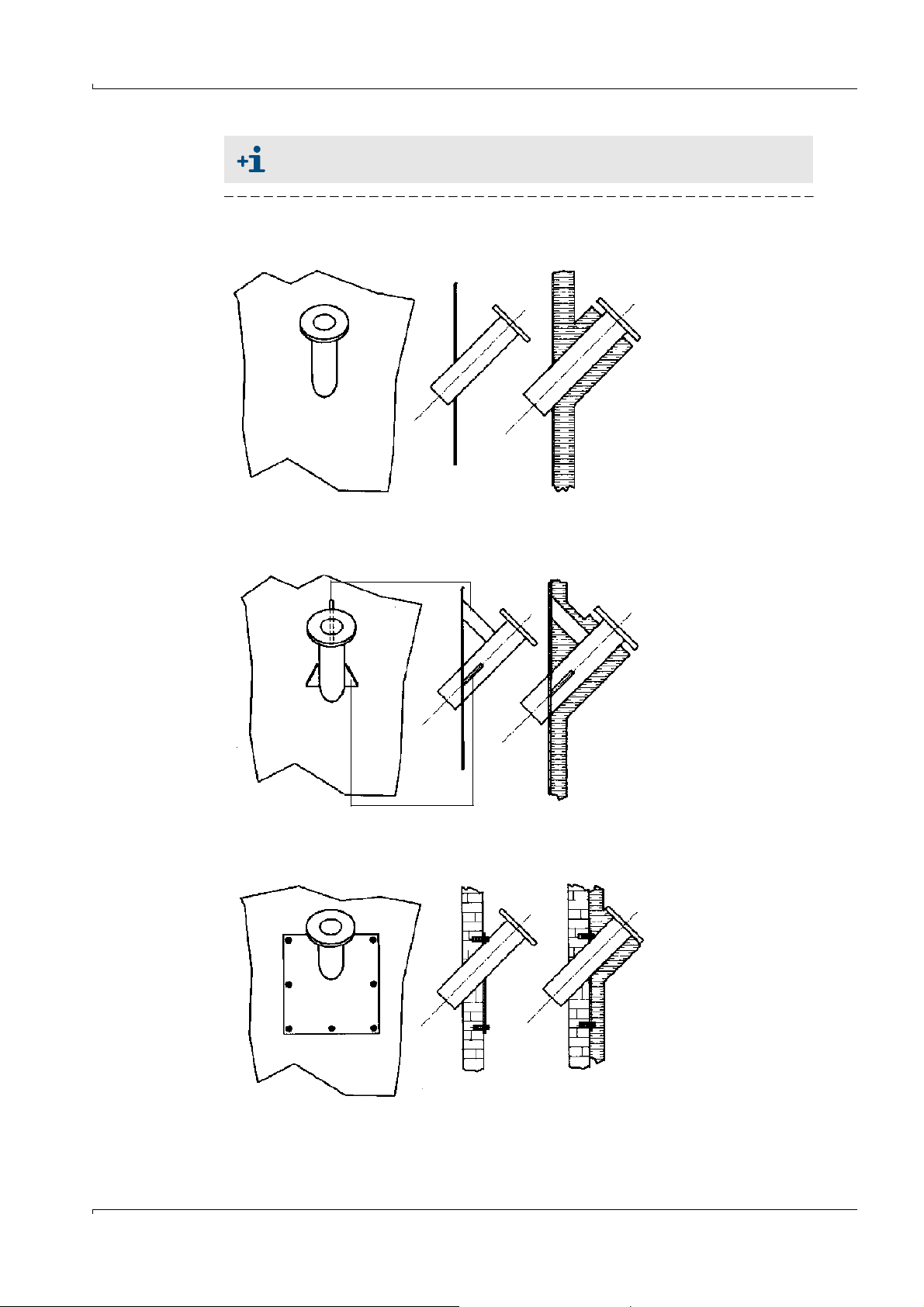
Assembly and Installation
Flange with tube welded to a stable and sturdy steel wall
Flange with tube welded to thin steel wall
Flange with tube mounted on brick or concrete duct
a) Duct without insulation
b) Duct with insulation
a) Duct without insulation
b) Duct with insulation
a) Duct without insulation
b) Duct with insulation
a) b)
a) b)
a) b)
Bracket
Reinforcement
When installing FLSE100-PR sender/receiver units, insert the flange with tube
as far as possible into the duct (with the longest possible length Le).
Fig. 34 Fitting options for the flange with tube
Subject to change w ithout notice
FLOWSIC100 · Operating Instructions · 8012513/YSA5/V 2-1/2016-07 · © SICK Engineering GmbH 61
Page 62

When fitting two flanges with tubes, align both exactly to each other after tacking using
1 Lamp in adjusting device
2 Lamp flange plate
3Flange tube
4Duct
5 Target optic flange plate
6 Target optic, visor
7 Sight with optimum alignment
4
3
2
1
5
7
A
A
6
a suitable tube (for smaller ducts) or using the SICK adjustment aid (can be provided on
loan) (see Fig. 35).
Fig. 35 Aligning the flange using the optical alignment device
Assembly and Installation
Align the flange with target optics so that the light spot of the lamp appears
in the center of the target optics.
Weld on the flange tubes, while constantly ensuring that the alignment is exact (correct
if necessary). When using the alignment device, first reposition the flange plate with
lamp and flange plate with target optics before welding the second flange tube on.
Measure and note the installation angle for configuring the parameters later.
Measure and note the distance between the two flanges (dimension F-F in Fig. 31) and
make a note of it for configuring the parameters later. The DME 2000 distance sensor
from SICK can be used (consult SICK, if required) for this purpose.
With thin-walled ducts/lines, provide suitable brackets/reinforcement to prevent distor-
tion and vibration (
Seal the flange with a blind plug (optional).
p. 61, Fig. 34).
Insulate the flange tube (if necessary).
● When mounting two flanges with tube, the alignment of the two flange
tubes has priority over the installation angle.
● Distortions as a result of temperature changes or mechanical stresses can
change the measuring path.
Subject to change w ithout notice
62 FLOWSIC100 · Operating Instructions · 8012513/YSA5/V2-1/2016-07 · © SICK Engineering GmbH
Page 63

Assembly and Installation
Fitting on both sides
Fitting on one side
Sender/receiver unit
*
*
Type FLSE100-M is shown
NL
w
x
Di
45°
±0.5°
Di = 0.15 ... 0.5 m
Sender/receiver unit
*
N
L
x
60°
±0.5°
b
(=10 mm)
b
(=8 mm)
L
FF
F
1
L
1
L
2
F
2
L = L1 + L2
FF = F1 + F2
3.2.1.2 Duct/tube diameter < 0.5 m
The work is generally the same as for larger diameters. The difference with small diameters
is that installing the flanges and sender/receiver units can have a greater impact on the
flow characteristics. To minimize this impact, the flange tubes should not be inserted in the
pipeline, but rather mounted and welded flush on the outside.
Two options are available for installation (
● On two sides
● On one side, using the sound reflection on the opposite inside wall. This solution can be
used with very small ducts to lengthen the measuring path, or if access is only possible
from one side.
Fig. 36 Fitting the flanges with tube
Fig. 36):
Subject to change w ithout notice
Carry out the following before fitting the flanges with tube:
FLOWSIC100 · Operating Instructions · 8012513/YSA5/V 2-1/2016-07 · © SICK Engineering GmbH 63
Page 64

Cut out suitable oval openings in the duct wall (see Annex for templates).
Di (mm) a (mm)
500 ... 290 0
290 ... 150 3
L
F
45°
60°
(87°) (87°)
48,3
a
L
F60
L
F45
L
F
NL x+=
L
F45
LF48.3–=
L
F60
LF27,9–=
x
48 3 35+
2 tan
----------------------- -
wb+
sin
------------------
–=
b
45° 10
60° 8
Bevel the flange tubes at an angle of 45
If necessary, adapt the flange tubes to the wall curvature as shown in Fig. 37.
Fig. 37 Adapting the flanges with tube
Assembly and Installation
° or 60°.
Flange tube length LF (L
nominal length NL (
formulas:
, L
F45
Fig. 36,
) depends on installation angle , wall thickness w and
F60
Fig. 37). This correlation is expressed by the following
64 FLOWSIC100 · Operating Instructions · 8012513/YSA5/V2-1/2016-07 · © SICK Engineering GmbH
Subject to change w ithout notice
Page 65

Assembly and Installation
A selection of values is provided in the following Table. The Table shows that flanges with
tube with the next longest nominal length than that of the sender/receiver units must be
selected.
Tube length LF, L
F45/LF60
at nominal length NL
NL=125 NL=200 NL=310 NL=350 NL=550
w x L
F
L
F45
L
F
L
F45
L
F
L
F45
L
F
L
F45
L
F
L
F45
45° 1 26.1 151.1 102.8 226.1 177.8 336.1 287.8 376.1 327.8 576.1 527.8
2 24.7 149.7 101.4 224.7 176.4 334.7 286.4 374.7 326.4 574.7 526.4
3 23.3 148.3 100.0 223.3 175.0 333.3 285.0 373.3 325.0 573.3 525.0
4 21.9 146.9 98.6 221.9 173.6 331.9 283.6 371.9 323.6 571.9 523.6
5 20.4 145.4 97.1 220.4 172.1 330.4 282.1 370.4 322.1 570.4 522.1
6 19.0 144.0 95.7 219.0 170.7 329.0 280.7 369.0 320.7 569.0 520.7
7 17.6 142.6 94.3 217.6 169.3 327.6 279.3 367.6 319.3 567.6 519.3
8 16.2 141.2 92.9 216.2 167.9 326.2 277.9 366.2 317.9 566.2 517.9
9 14.8 139.8 91.5 214.8 166.5 324.8 276.5 364.8 316.5 564.8 516.5
10 13.4 138.4 90.1 213.4 165.1 323.4 275.1 363.4 315.1 563.4 515.1
w x L
F
L
F60
L
F
L
F60
L
F
L
F60
L
F
L
F60
L
F
L
F60
60° 1 13.7 138.7 110.8 213.7 185.8 323.7 295.8 363.7 335.8 563.7 535.8
2 12.5 137.5 109.6 212.5 184.6 322.5 294.6 362.5 334.6 562.5 534.6
3 11.3 136.3 108.5 211.3 183.5 321.3 293.5 361.3 333.5 561.3 533.5
4 10.2 135.2 107.3 210.2 182.3 320.2 292.3 360.2 332.3 560.2 532.3
5 9.0 134.0 106.1 209.0 181.1 319.0 291.1 359.0 331.1 559.0 531.1
6 7.9 132.9 105.0 207.9 180.0 317.9 290.0 357.9 330.0 557.9 530.0
7 6.7 131.7 103.8 206.7 178.8 316.7 288.8 356.7 328.8 556.7 528.8
8 5.6 130.6 102.7 205.6 177.7 315.6 287.7 355.6 327.7 555.6 527.7
9 4.4 129.4 101.5 204.4 176.5 314.4 286.5 354.4 326.5 554.4 526.5
10 3.3 128.3 100.4 203.3 175.4 313.3 285.4 353.3 325.4 553.3 525.4
Matching flanges with tube can be provided by SICK on request (please specify with order).
Alternatively, a tube piece with premounted flanges can be ordered from SICK.
A tube with suitable diameter can be used to align the flange tubes for face-to-face
mounting.
After welding, determine and note measure F-F (
Subject to change w ithout notice
FLOWSIC100 · Operating Instructions · 8012513/YSA5/V 2-1/2016-07 · © SICK Engineering GmbH 65
p. 63, Fig. 36) for later parameter setting.
Page 66
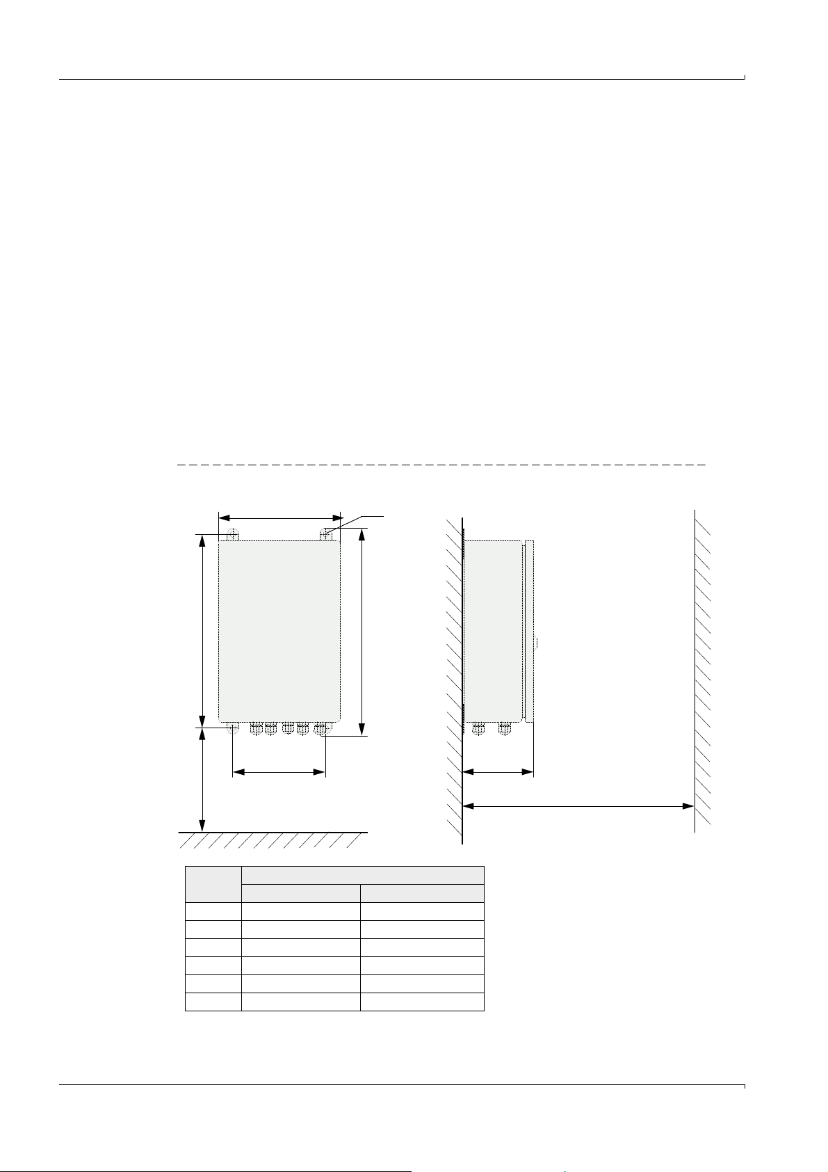
3.2.2 Installing the control unit
c
f
e
> 250
d
b
M8
Clearance for opening the door
Clearance for cable
a
Measure Connection unit type
MCU-N MCU-P
a 160 260
b 320 420
c 210 300
d 340 440
e 125 220
f > 350 > 540
MCU-N: Control unit without
cooling air supply
MCU-P: Control unit with
cooling air supply
(
p. 176, 6.3.3)
The control unit must be mounted on a level base at an accessible, protected location as
shown in Fig. 38. The following must be taken into account:
● Maintain the ambient temperature range in accordance with the Technical Data under
consideration of possible radiant heat (shield when necessary).
● Protect the unit from direct sunlight.
● Select an installation location free from vibrations when possible and stabilize vibra-
tions when necessary.
● Provide sufficient clearance for cables and opening the front panel.
Providing suitable cables are used (see Section
(version without integrated blower) can be installed up to 1000 meters from the sender/
receiver unit (use bus lines in accordance with Fig. 73; length is the overall length of all
cables). For easier access to the MCU, we recommend installing it in a control room
(measuring station or similar). This facilitates communication with the FLOWSIC100 for
configuration or troubleshooting.
If the device is to be installed outdoors, a weatherproof cover for the control unit or
equivalent cover (corrugated roof) must be provided onsite.
Assembly dimensions
Assembly and Installation
p. 97, 3.3.6), the MCU-N control unit
Fig. 38 MCU assembly dimensions
66 FLOWSIC100 · Operating Instructions · 8012513/YSA5/V2-1/2016-07 · © SICK Engineering GmbH
Subject to change w ithout notice
Page 67

Assembly and Installation
Clearance for cable
> 150 > 15080
52
M4
113
125
Prerequisite for using the control unit MCU-P (for FLSE100-MAC and HAC)
Additionally to the general requirements the following is prerequisites apply:
● Install the MCU-P at a location with clean air whenever possible. The intake temperature must match the values specified in the Technical Data (
lay an air intake hose at a location where conditions are more favorable.
●
The purge air hoses DN25 (Part No. 7047535 and 7047536) to both sender/receiver
units should be as short as possible They must be of equal length (max. hose length in
each case 10 m).
● The purge air hoses should be laid in such a way that water cannot collect.
Additional requirements when the control unit MCU must be installed more than 10 m
away from the measuring point:
– Use of a separate cooling air unit in the connection box (dimensions and assembly
dimensions as for MCU-P; Part No. 2070816 and 2070817)
– Use of the control unit in version MCU-N (without integrated blower unit)
3.2.3 Installing the junction box
Install these subassemblies on a level base plate (secure with 2 M4x20 bolts).
Fig. 39 Junction box assembly dimensions
p. 166, 6.1). If necessary,
3.2.4
Subject to change w ithout notice
FLOWSIC100 · Operating Instructions · 8012513/YSA5/V 2-1/2016-07 · © SICK Engineering GmbH 67
Suitable fastening sets are available for installation on stone / concrete
ducts.
Installing the sender/receiver units
Check the following points before installing the sender/receiver units in the prepared
flange tubes:
● Connections and sender/receiver units must be compatible (
● The inside walls of the connections must be completely free from welding beads.
● Optional: Fitting an impact protector on the sender/receiver unit (
Push the sender/receiver units into the flange tubes and fit these on the flange with the
delivered bolts and the optional structure-borne noise damping set.
p. 28, 2.3.2).
p. 72, 3.2.8)
Page 68

3.2.5 Installation of the weatherproof cover for the sender/receiver units
Fix the holder to the sender/receiver
unit:
– Use the fixing accessories to attach
the holder with round steel bow to
the probe neck of the FLSE100
– Pay attention to the correct align-
ment of the holder. See adjacent figure.
Assembly and Installation
Position the protective hood on the
holder.
Secure the weather protection with the
split pin.
Subject to change w ithout notice
68 FLOWSIC100 · Operating Instructions · 8012513/YSA5/V2-1/2016-07 · © SICK Engineering GmbH
Page 69

Assembly and Installation
> 160
(550)
Duct
Clearance for replacing filter element
> 140
(550)
Purge air hose
Purge air hose
Clearance
for fitting of
weatherproof cover
470
470
Alternative: Mounting bracket
50 x 5 steel pipe
DIN 2391
50
M 8
3.2.6 Installing the purge air unit option (device type PM, PH, PH-S)
The steps below are only necessary when purged sender/receiver units are required.
The following points must be taken into account when selecting the installation location:
● The purge air unit must be installed in a location with clean air. The intake temperature
must match the values specified in the Technical Data (
an air intake hose at a location where conditions are more favorable.
● The fitting location must be easily accessible and meet all applicable safety requirements.
● The purge air unit must be mounted as far below the sender/receiver units as
necessary, so that the purge air hoses can be installed leading downwards to the purge
air unit (avoiding water collection).
● Provide sufficient clearance for replacing the filter element.
● Provide sufficient clearance for fitting and raising the weatherproof cover when the
purge air unit is installed outdoors (
Fig. 40 Mounting the purge air unit
Fig. 40).
p. 166, 6.1). If necessary, lay
Subject to change w ithout notice
FLOWSIC100 · Operating Instructions · 8012513/YSA5/V 2-1/2016-07 · © SICK Engineering GmbH 69
Page 70

Assembly and Installation
1 Sender/receiver unit
2 Hose clamp (scope of delivery for
emergency air supply)
3Adapter
4 Quick connector
5 Compressed air hose
6 Quick connector, paired
7 Reducer
8 Solenoid valve
9 Coupling
10 Purge air base plate
11 Purge air hose
1
2
3
5
6
7
8
9
10
11
4
Compressed air onsite
Installation work
Prepare the bracket in accordance with Fig. 40 (page 69).
Secure the purge air unit with 4 bolts (M8).
Check the filter element is in the filter housing, insert when necessary.
3.2.7 Installing the emergency air supply option for device types PM, PH and PH-S
The subassemblies are delivered pre-assembled. Connect adapters (3) to the purge air
connections of the S/R units and fasten with the hose clamps (scope of delivery) (
Fit and wire the solenoid valve on the purge air base plate (see connection
Fig. 41).
p. 93, 3.3.4.2,
Fig. 64 - Fig. 66). Insert compressed air hoses (5) paired in quick-connectors (6) and fasten
on quick connector (4). These must always have the same length.
Fig. 41 Connection - emergency air supply for one purge air unit
Subject to change w ithout notice
70 FLOWSIC100 · Operating Instructions · 8012513/YSA5/V2-1/2016-07 · © SICK Engineering GmbH
Page 71

Assembly and Installation
1 Sender/receiver unit
2 Hose clamp (scope of delivery for emergency air
supply)
3Adapter
4 Quick connector
5 Compressed air hose
6 Reducer
7 Solenoid valve
8 Coupling
9 Purge air base plate
10 Purge air hose
1
2
3
5
9
10
4
4
7
8
6
6
Compressed air onsite
Fig. 42 Connection - emergency air supply for two purge air units
Insert the backflow valves (for overpressure in duct) directly on the Y-distributor of the
purge air blower (remove the existing purge air hose) and fasten with hose clamps (Fig. 43).
Subject to change w ithout notice
FLOWSIC100 · Operating Instructions · 8012513/YSA5/V 2-1/2016-07 · © SICK Engineering GmbH 71
Page 72

Fig. 43 Fitting the backflow valve
1 Purge air unit
2 Backflow valve
3Stop
4 Hose clamp
5 Purge air hose
1
2
2
3
4
5
Assembly and Installation
3.2.8
Installing the weatherproof cover for the purge air unit option
The weatherproof cover consists of a cover and lock set.
Fit the lock parts from the lock set on the base plate.
Fit the weatherproof cover from above.
Insert the side lock bolts in the counterparts, rotate and latch into place.
Subject to change w ithout notice
72 FLOWSIC100 · Operating Instructions · 8012513/YSA5/V2-1/2016-07 · © SICK Engineering GmbH
Page 73

Assembly and Installation
Impact protector
Flow direction
Impact protector
Flow direction
3.2.9 Installting the impact protector / dust protector options
3.2.9.1 Impact protection for FLSE100-H, HAC, PH and PHS
The impact protector option is intended for the use of the FLOWSIC100 in high dust
applications with particle sizes >0.5 mm. Installing this component provides effective
protection for the surface of the ultrasonic transducer against particle impact.
It is normally sufficient to fit the impact protector on the downstream sender/receiver unit
(probe B) (p. 15, Fig. 4).
Assembly
Fit on types PH and PHS with the securing bolts of the transducers.
Installing the impact protector option for types PH and PHS
Fig. 44 Installing the impact protector option for types PH and PHS
The impact protector is located on the probe head as shown in Fig. 44 and must be aligned
facing the flow direction.
Fit on type H to the securing holes provided on the probe head using the delivered
securing bolts
Fig. 45 Installing the impact protector option for type H
Subject to change w ithout notice
The impact protector is located on the probe head as shown in Fig. 45 and must be aligned
facing the flow direction.
FLOWSIC100 · Operating Instructions · 8012513/YSA5/V 2-1/2016-07 · © SICK Engineering GmbH 73
Page 74

Assembly and Installation
Punch
Follow the following instructions for installing the impact protector for type HAC.
Installing the impact protector option for type HAC
Fold the impact protector plate around
the transducer and press the angled
clips into the recesses on the opposite
side of the plate.
Keep folding the clips towards the folded
edge until they touch the plate.
Align the impact protector facing the flow
direction and use a punch to drive the
crosswise recesses into the four
mounting holes of the transducer.
74 FLOWSIC100 · Operating Instructions · 8012513/YSA5/V2-1/2016-07 · © SICK Engineering GmbH
Subject to change w ithout notice
Page 75

Assembly and Installation
The dust protector is mounted on
the securing bolts of the transducer carrier.
Dust protector
A - A
Dust protector
Transducer
A
A
Flow direction
3.2.9.2 Dust protector for FLSE100-PR
The optionally available dust protector PR can be used when dust contamination on the
transducer surface of the single-probe version FLSE100-PR causes a problem. This option
is designed to prevent possible contamination of dust on the ultrasonic transducers. It
comprises the components ‘‘right dust protector” and ‘‘left dust protector”. Fit the
components to the downstream sides of the transducers in accordance with Fig.46.
Fig. 46 Fitting of the dust protector option on type FLSE100-PR
NOTICE:
The effectiveness of the dust protector depends on the dust texture and flow
conditions in the duct and can therefore considerably vary.
3.2.10 Installing the structure-borne noise damping set option K100/K75
In some installations, vibrations in the resonance range of the ultrasonic transducer come
from the system over the flange to the sender/receiver units and therefore have an effect
on the transducer and create interference signals (direct acoustic coupling). The optional
structure-borne noise damping set K100/K75 can be used to prevent such disturbances. It
comprises additional gaskets, cup springs and washers as well as appropriate longer
securing bolts, which are used for fitting the sender/receiver units.
A damping set is already included in the assembly material at the factory for device types
M, H, M-AC and H-AC. The set serves to prevent coupling of structure-borne noise from the
system in the ultrasonic transducer. The assembly/damping set is delivered as shown in
Fig. 47 and is ready for installation.
Subject to change w ithout notice
FLOWSIC100 · Operating Instructions · 8012513/YSA5/V 2-1/2016-07 · © SICK Engineering GmbH 75
Page 76

Fig. 47 Assembly/damping set - scope of delivery
Designation Part No. For type FLSE100
Assembly/
damping set
K100
2056565 FLOWSIC100 H, H-AC
Assembly/
damping set
K75
2056564 FLOWSIC100 M, M-AC
Assembly/
damping set
K75/K100
2042503
For retrofitting on existing
installations:
FLOWSIC100 M, M-AC, H,
H-AC
Assembly and Installation
76 FLOWSIC100 · Operating Instructions · 8012513/YSA5/V2-1/2016-07 · © SICK Engineering GmbH
Subject to change w ithout notice
Page 77

Assembly and Installation
Flange with thread
Flange seal
Seals
Spring washers
Screw
Bushing
Silicone absorber
Flange seal
Fig. 48 Installing the assembly/damping set
Installation instructions structure-borne noise damping set K100/K75
Position the flange seal between the flange plates
Fit the screws with all delivered parts in the flange (see Fig. 48)
NOTICE:
Tighten the screws until the gap between the spring washer sets is no lon-
ger visible.
Then loosen the screw by ¼ turn until the gap between the spring washer
sets is visible again to ensure full damping effect.
NOTICE:
The additionally provided flange seal can be installed to increase the damping
effect if high interference signals continue despite using the structure-borne
Subject to change w ithout notice
noise damping set.
FLOWSIC100 · Operating Instructions · 8012513/YSA5/V 2-1/2016-07 · © SICK Engineering GmbH 77
Page 78

3.3 Installation
3.3.1 General instructions, prerequisites
Carry out the steps described in p. 60, 3.2 before starting installation work.
Unless otherwise agreed with SICK or an authorized representative, all of the installation
work must be carried out by the plant operator. This includes:
Laying all the power supply and signal cables
Connecting the power supply and signal cables to the system components
Installing the switches and mains fuses
Carry out the additional work described in Section § 3.3.2 when using the purge air unit
option.
Plan adequate line cross-sections (p. 166, 6.1 "Technical Data")
The cable ends with plug for connecting the sender/receiver units must be
long enough.
Cable connectors that are not connected must be protected from dirt and
moisture (fit cover).
WARNING:
● All installation work must be carried out in line with the relevant safety
regulations and instructions listed in Chapter 1.
● Suitable protective measures must be taken to protect against local or
system-specific danger.
Assembly and Installation
3.3.2 Installing the purge/cooling air supply
The following steps are only necessary when internally cooled or purged sender/receiver
units must be used.
Lay the purge/cooling air hoses on short routes and without kinks, shorten if necessary.
Leave sufficient clearance to hot duct walls.
Ensure cooling air (type M-AC and H-AC) can escape freely when installing on isolated
ducts (
p. 25, Fig. 11, Fig. 2.3.1.3)
78 FLOWSIC100 · Operating Instructions · 8012513/YSA5/V2-1/2016-07 · © SICK Engineering GmbH
Subject to change w ithout notice
Page 79

Assembly and Installation
Terminals for mains connection Cooling air outlet DN 25
Cooling air
3.3.2.1 Control unit MCU-P with integrated cooling air supply (device type M-AC and H-AC)
Connect the mains cable to terminals L1, N and PE on the terminal strip.
Connect the DN 25 purge air hose to the cooling air outlet on the underside of the
MCU-P (
p. 79, Fig. 49) and secure it with a strap retainer. The cooling air outlet in the
middle must be adjusted as displayed (correct if necessary).
Fig. 49 Underside of control unit with integrated cooling air supply
3.3.2.2 Separate cooling air supply in connection box (device type M-AC and H-AC)
Connect the mains cable to terminals L1, N and PE on the terminal strip.
Connect the DN 40 cooling air hose to the cooling air outlet on the underside of the
junction box (
Fig. 50) and secure it with a strap retainer. The cooling air outlet in the
middle must be adjusted as displayed (correct if necessary).
NOTICE:
Same connections at use of the separate cooling air supply in connection box
(
Fig. 49).
Subject to change w ithout notice
FLOWSIC100 · Operating Instructions · 8012513/YSA5/V 2-1/2016-07 · © SICK Engineering GmbH 79
Page 80

3.3.2.3 Purge air unit (device type PM, PH, PH-S)
Power supply
4 x 1.5 mm
2
L1 L1
U1 U1
U1
U1
V1 V1
V1
V1
W1 W1
W1
W1
PE PE
W2 W2
W2
W2
V2 V2
V2
V2
U2 U2
U2
U2
L2 L2
+
24 V
L3 L3
_
PE PE
Low-pressure sensor
Installed onsite
Motor
circuit
breaker
delta connection star connection
Blower motor in
Compare the mains voltage and frequency with those specified on the type plate of the
purge air motor.
NOTICE:
Do not connect the purge air unit if the values do not match.
Connect the power supply cable to the terminals on the purge air motor (see supple-
mentary sheet on purge air motor and cover of motor terminal box; connection arrangement
Fig. 50).
Connect a protective conductor to the terminal.
Set the motor circuit breaker in accordance with the connection data of the blower (see
technical data of purge air unit) to a value 10% greater than the rated current.
Check the functioning and running direction of the blower (flow direction of the purge
air unit must match the arrows on the inlet and outlet openings on the blower). Incorrect running direction on 3-phase motors: Swap mains connections L1 and L2.
Connect the (optional) pressure controller for monitoring the purge air supply.
NOTICE:
Use a fail-safe power supply (emergency voltage supply, bar with redundant
supply)
The purge air unit must be fused separately from the other system
components. The fuse type must match the rated current (see technical
details of purge air unit). Fuse each phase separately. Provide circuit
breakers to protect against a phase failure on one side.
Assembly and Installation
In case of doubt or when using a special motor version, the operating instructions supplied
with the motor have priority over any other information.
Fig. 50 Electrical connections for the purge air unit option
Subject to change w ithout notice
80 FLOWSIC100 · Operating Instructions · 8012513/YSA5/V2-1/2016-07 · © SICK Engineering GmbH
Page 81

Assembly and Installation
approx. 200 mm
Reducer
Purge air/cooling air hose to
the sender/receiver unit
Clamping tape
Purge air/cooling air
unit hose connection
3.3.2.4 Installing the purge air and cooling air reducer option
If necessary, install a purge air reducer for FLOWSIC100 PM, PH, PHS or a cooling air
reducer for FLOWSIC100 MAC, HAC according to
Fig. 51 Purge air unit
Fig. 51.
NOTICE: Cooling air reducer for FLOWSIC100 MAC, HAC
Usually, it is not necessary to install the reducing pieces during regular
operation.
Installation can become necessary when the measuring system runs in an
extreme range due to unfavorable application conditions and noise effects
of the cooling air have to be reduced.
In particular cases, the effectiveness of the cooling air reducer has to be
checked by a trained service technician during start-up of the measuring
system.
Subject to change w ithout notice
FLOWSIC100 · Operating Instructions · 8012513/YSA5/V 2-1/2016-07 · © SICK Engineering GmbH 81
Page 82

Assembly and Installation
3.3.3 Installing the cooling air control option for device types M-AC and H-AC
a) System configuration with control unit MCU-P (with integrated blower unit)
System configuration with control unit MCU-N + cooling air supply 24 V DC in junction
box
Snap the solid-state relay into place on the MCU top hat rail.
Disconnect the blue lead of the connection to the cooling air blower from MCU terminal
47 and connect it to the white lead of the solid-state relay (from relay terminal +13)
using a lamp-wire connector.
Connect the brown lead of the solid-state relay (relay terminal 14) to MCU terminal 47
(gnd blower).
Connect MCU terminal 13 (com limit) and terminal 30 (gnd) with a black jumper.
Connect terminal A2 (-) of the solid-state relay to MCU terminal 15 (n.o. limit).
Connect terminal A1 (+) of the solid-state relay to MCU terminal 29 (+ 24 V DC)
See terminal connection diagram
p. 85, Fig. 54
b) System configuration with control unit MCU-N + cooling air supply 230 V AC in junction
box
Same connection as the configuration in a) but with the following change:
– Connect terminals 13 and 14 of the solid-sate relay to the power supply 24 V DC for
the external blower unit.
See terminal connection diagram
NOTICE:
The colors of the leads between the solid-state relay and MCU only serve as
examples and can vary depending on the delivery
p. 86, Fig. 55
82 FLOWSIC100 · Operating Instructions · 8012513/YSA5/V2-1/2016-07 · © SICK Engineering GmbH
Subject to change w ithout notice
Page 83

Assembly and Installation
Solid-state relay
Connection terminal:
L1: +24 V
L2: gnd
Blower unit
Fig. 52 Electrical connection of the cooling air control option for the MCU-N + cooling air supply 24 V DC in
connection box
Subject to change w ithout notice
NOTICE:
The solid-state relay is installed in the cooling air supply housing on systems
with cooling air supply 230 V AC in connection box.
FLOWSIC100 · Operating Instructions · 8012513/YSA5/V 2-1/2016-07 · © SICK Engineering GmbH 83
Page 84

Assembly and Installation
Fig. 53 Electrical connection of the cooling air control option for the MCU-P with integrated blower unit
84 FLOWSIC100 · Operating Instructions · 8012513/YSA5/V2-1/2016-07 · © SICK Engineering GmbH
Subject to change w ithout notice
Page 85

Assembly and Installation
Cable onsite
Cable
onsite
To internal blower (MCU-P) /
external blower (MCU-N)
Processor board
White
Pink
Black
Grey
Blue
Brown
Brown
Lamp-wire
connector
Solidstate
relay
Fig. 54 Connection between cooling air control on MCU-P and MCU-N with external blower unit 24 V DC
Subject to change w ithout notice
FLOWSIC100 · Operating Instructions · 8012513/YSA5/V 2-1/2016-07 · © SICK Engineering GmbH 85
Page 86

Assembly and Installation
Internal 24 V DC
power supply of
the MCU for the
blower unit
Solid-state relay
Red
Blower
External blower unit in junction box
To MCU terminal 29 To MCU terminal 15
Grey
Blue
Brown
Cable specification for the power supply of the external blower unit in connection box
The following demands with regard to wire cross-sectional area and specific resistance
must be considered for the supply cable to ensure the power supply for the external blower
unit.
Wire cross-sectional area
2
mm
Specific resistance in
Ω/km
Max. cable length in m
0.5 40 25
0.75 25 40
1.00 18 55
1.5 14 70
2.5 8 130
A separate power supply is required for the blower unit for distances greater than 130 m
between the MCU-N and external blower unit. In this case, use the cooling air supply in
connection box with connection 230 V AC.
Fig. 55 Connection of the cooling air control option when using MCU-N 230 V AC with external blower unit 24 V DC
86 FLOWSIC100 · Operating Instructions · 8012513/YSA5/V2-1/2016-07 · © SICK Engineering GmbH
Subject to change w ithout notice
Page 87

Assembly and Installation
Emergency operation with compressed air
Compressed air primary pressure [bar]
Volume flow [m3/h]
Air
inlet
Air outlet
Compressed
air connection
3.3.4 Installing optional sets for emergency air supply for devices with purge/cooling air
operation
3.3.4.1 Emergency air supply for device types M-AC and H-AC
The "emergency air supply FLOWSIC100 M-AC and H-AC“
subassemblies. (
Fig. 56 Primary pressure set and resulting cooling air volume flow
p. 87, Fig. 56)
is delivered pre-assembled in its
Fig. 57 Layout and functional diagram of cooling air supply with emergency air option
Subject to change w ithout notice
FLOWSIC100 · Operating Instructions · 8012513/YSA5/V 2-1/2016-07 · © SICK Engineering GmbH 87
Page 88

Table 1 Standard components
1 FLSE100-HAC or MAC Standard component
5 Hose clamp Standard component
6 Flexible cooling air hose Standard component
7
Table 2 Components for the emergency air supply option M-AC, H-AC
MCU-P with integrated blower
unit
Standard component
Junction box for solenoid valve
2
a) Solenoid valve
b) Connection plug
c) Y adapter
Emergency air valve
3
a) Backflow valve DN25
b) Screw fitting
4 Emergency air line (instrument air)
Connect emergency air valves (3) between flexible DN 25 cooling air hoses (6) and the
cooling air inlet of the S/R units using hose clamps (5). The different connection diameters
determine the assembly direction (in flow direction) of emergency air valves (3).
Connect emergency air lines (4) (switched compressed air) via quick-connectors to Y
branch (2c) on junction box solenoid valve (2) and screw fittings (3b) on emergency air
valves (3). Connect the compressed air supply (instrument air free from oil, grease and
water) via connection plug (2b).
Arrange the MCU (7), S/R units, supply lines and junction box solenoid valve so that both
flexible DN25 cooling air hoses(6) from the MCU blower unit and emergency air lines (4)
from junction box solenoid valve (2) to both S/R units have the same length (same
pressure loss, same amount of cooling air on FLSE100 A and B).
Assembly and Installation
88 FLOWSIC100 · Operating Instructions · 8012513/YSA5/V2-1/2016-07 · © SICK Engineering GmbH
Subject to change w ithout notice
Page 89

Assembly and Installation
To solenoid valve
Blower
a) Valve open
b) Air test / opening control
Electrical installation
Fig. 58 Solenoid valve electrical connection
Make a 2-wire connection to the solenoid valve (blade terminal). There are no
requirements on polarity because the pulling magnet is electrically isolated from the valve
body.
Pulling magnet connection values: 24 V DC; 0.43 A continuous current.
Function test in normal operation with MCU blower unit
a) Start the blower by switching the MCU on.
When using the optionally available "cooling air control for device types M-AC and H-AC",
start blower operation in a suitable manner; e.g. with a fixed blower connection on the 24 V
rail or bridging the relay.
b) Remove the emergency air valves (
p. 89, Fig. 59) and start the MCU blower.
The blowing air flow must lift the valve plate evenly approx. 2 mm out of its seating and the
cooling air flow passing through must be clearly felt. When necessary, close off the other
line.
Lift the valve plate mechanically when the valve sticks in its seating (long storage time).
Then repeat the test to ensure the blower can open the valve on its own.
Fig. 59 Removing and throughflow test on the emergency air valves
Subject to change w ithout notice
FLOWSIC100 · Operating Instructions · 8012513/YSA5/V 2-1/2016-07 · © SICK Engineering GmbH 89
Page 90

Function test emergency air operation with instrument air
Direction test
emergency air
Flow direction
Blocking direction
Make a compressed air connection between the junction box for solenoid valve (2) and
emergency air valve (3) as shown in (
Separate the emergency air valve from the cooling air hoses and S/R units.
Switch the MCU supply voltage off - solenoid valve (2a) must switch audibly and release
the instrument air flow.
Emergency air flow direction test - see (
Fig. 60 Emergency air direction test
p. 87, Fig. 57).
Fig. 60).
Assembly and Installation
The air flow in flow direction must be noticeable (approx. 2.8 l/s). No significant leakage
flow should flow in the blocking direction (
Fig. 60). Leakage rates up to 3% of the nominal
air flow are allowed.
Repeat the test shown in Fig. 60 with the S/R unit connected (
air should still also be clearly felt on the probe exhaust slots (
Finally, reconnect all connections as shown in (
p. 87, Fig. 57), reset any changed
p. 87, Fig. 57). The escaping
p. 87, Fig. 57).
parameters and set the device to the operating state.
Maintenance
The emergency air supply should be able to bridge temporary cooling air failures up to 24
hours. Measuring operation could be interrupted during this time (noise disturbance due to
increased instrument air noise).
It is recommended to take the S/R units out of the sample gas duct during longer term
restrictions or complete failure of the standard cooling air supply.
Check parts carrying air as shown in (
p. 87, Fig. 57) after longer emergency air operation:
Remove the DN 25 cooling air hoses and check the insides for condensate, oil and
general contamination. Clean the insides of the hoses when necessary and replace
hoses with heavy contamination. Use hoses with the same length for both S/R units.
Remove the emergency air valves and open to check (
p. 89, Fig. 59).
Remove any contamination and dry the valve, replace emergency air valve (3) when
contamination is heavy or when the valve is damaged (spring, valve plate, rubber seal).
Apply talcum powder to the dry rubber seal of the valve plate to prevent the valve plate
sticking in the seating.
Carry out the opening and blocking direction function check as shown in (
p. 90, Fig.
60).
Subject to change w ithout notice
90 FLOWSIC100 · Operating Instructions · 8012513/YSA5/V2-1/2016-07 · © SICK Engineering GmbH
Page 91

Assembly and Installation
2
1
1. Solenoid valve central screw
2. Hexagonal solenoid valve
Remove the DN25 cooling air hoses from the MCU outlet and check the MCU outlet for
any moisture inside (possibly from compressed air, leakage flow).
Open the air filter housing in the MCU and check the paper filter element.
Replace the filter element when penetrated by moisture or extremely contaminated - air
filter replacement - analog OI Section 5.3.
Solenoid valve maintenance/repairs
Open the junction box for the solenoid valve.
Test switch the solenoid valve with varying compressed air primary pressures (1...3 bar).
Should valve switching fail, use central screw (1) (
to open the valve.
Screw the tension rod out above hexagon (2) (
Fig. 61 Opening the solenoid valve
WARNING:
The solenoid valve surface can be hot (> 70°C).
p. 91, Fig. 61) on the solenoid switch
p. 91, Fig. 61).
The valve seating is now open (
Fig. 62) and can be cleaned when necessary.
WARNING:
Do not use any sharp objects.
Fig. 62 Valve seating / sealing surface in solenoid valve
Subject to change w ithout notice
Replace the complete solenoid valve when heavily contaminated and/or corroded.
FLOWSIC100 · Operating Instructions · 8012513/YSA5/V 2-1/2016-07 · © SICK Engineering GmbH 91
Page 92

Fig. 63 Solenoid valve, electrical part; pulling magnet with anchor / sealing punch
Assembly and Installation
Spray a little spray oil in the ring gap (
sluggish (switching test when removed)
Fig. 63) when the anchor in the pulling magnet is
Fig. 63).
Parts overview
Part No. Description
2051484 Emergency air supply 24V for MCU
92 FLOWSIC100 · Operating Instructions · 8012513/YSA5/V2-1/2016-07 · © SICK Engineering GmbH
Subject to change w ithout notice
Page 93

Assembly and Installation
Purge air unit
Motor circuit breaker
(onsite)
Junction box
Purge air blower
Solenoid valve *)
*) In SICK scope of delivery but not fitted
Purge air unit
Motor circuit breaker
(onsite)
Junction box
Purge air blower
Solenoid valve *)
*) In SICK scope of delivery but not fitted
3.3.4.2 Emergency air supply for device types PM, PH and PHS
Fig. 64 Connection for operating voltage 230 V AC
Fig. 65 Connection for operating voltage 380 V AC (without phase sensor)
Subject to change w ithout notice
FLOWSIC100 · Operating Instructions · 8012513/YSA5/V 2-1/2016-07 · © SICK Engineering GmbH 93
Page 94
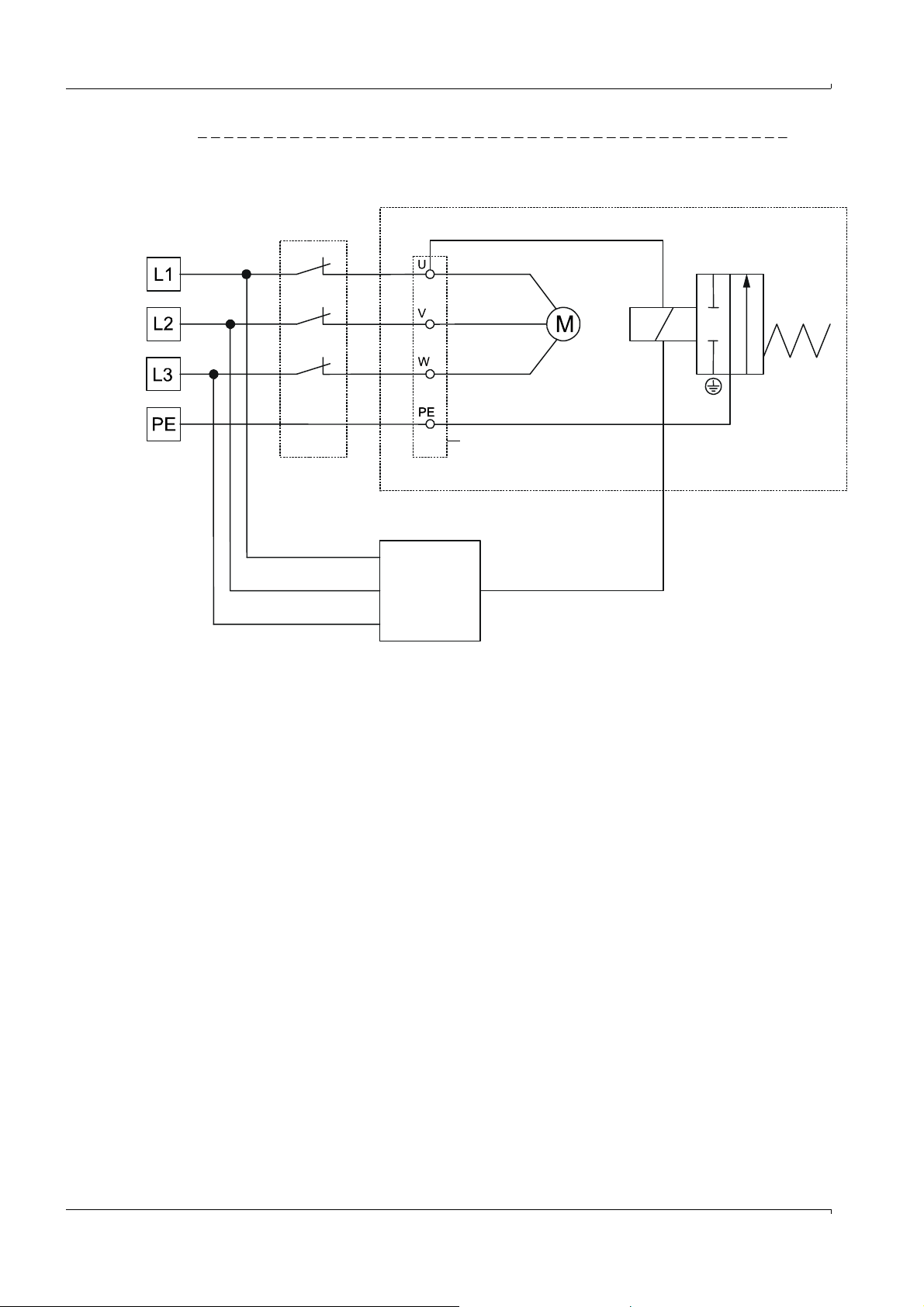
Assembly and Installation
Purge air unit
Motor circuit breaker
(onsite)
Junction box
Purge air blower
Solenoid valve *)
*) In SICK scope of delivery but not fitted
Phase sensor
(onsite)
Fig. 66 Connection for operating voltage 380 V AC with phase sensor for monitoring failure of any phase
94 FLOWSIC100 · Operating Instructions · 8012513/YSA5/V2-1/2016-07 · © SICK Engineering GmbH
Subject to change w ithout notice
Page 95

Assembly and Installation
3.3.5 Installing the sender/receiver unit
Check the following points before installation:
The sender/receiver units must have at least the same nominal length as the flanges
with tube.
The inside of the flange tubes must be free of welding beads.
The inside of the probe tubes on the sender/receiver units must not come into contact
with the flange tubes.
The cable connection on the electronics unit for sender/receiver units with digital signal
transmission must be at the bottom.
For type FLSE100-PR and under consideration of the fitting specifications as
shown in Fig. 29, when necessary, loosen the screw connections between the
electronics unit and PR connection, rotate the device to the required position
(90
°, 180°, 270°) and then screw the parts back together again.
Cooling air supply for sender/receiver units with internal cooling FLSE100-MAC/HAC
Check/ensure the cooling air supply is in operation.
Connect the cooling air hose DN25 to the cooling air connection on the sender/receiver
unit (mount the hose clamp on the free hose end, connect the cooling air hose and
secure it with the hose clamp).
Make sure cooling air is fed from below and discharged from below (see Fig. 67).
If this is not guaranteed, loosen the screwed connections between the cooling air con-
nection and the duct probe, rotate the unit accordingly (90
parts back together again
If the optional cooling air supply in connection box is used, slide the free end of the
cooling air hose on adapter 40-25 and secure it with the hose clamp.
°, 180°, 270°), and screw the
Subject to change w ithout notice
FLOWSIC100 · Operating Instructions · 8012513/YSA5/V 2-1/2016-07 · © SICK Engineering GmbH 95
Page 96

Assembly and Installation
Duct
Gas flow
Ultrasonic
transducer
Discharged
purge air
Gas flow
Cable connection
Purge air feed
Cable connection
Purge air feed
Discharged
purge air
Purge air supply for purged sender/receiver units FLSE100-PM, PH, PHS
To minimize corrosion when using corrosive gases, ensure the nominal lengths of the
sender/receiver units are at least one length longer than the nominal lengths of the
flanges with tube (
p. 27, 2.3.1.3).
Check/ensure the purge air supply is in operation.
Connect the purge air hoses, to do this, connect the hose clamp loosely on the free
hose end, connect the purge air hose to the purge air connection on the sender/
receiver units, and secure it with the hose clamp.
Check/ensure the purge air is fed from below and the purge air flows out in the direction of the gas flow.
Fig. 67 Alignment of cable connection and purge air supply for purged sender/receiver units (shown for type
FLSE100 PM/PH, fitted on a vertical duct)
Installation and electrical connection
WARNING:
Only install the sender/receiver units when it is safe to do so (for example,
when the system has been shut down, see
p. 9, 1.3.3).
Remove the blind plug from the flange.
Insert the sender/receiver units in the flanges with tube as previously described and
screw the components together.
Connect the cable to the control unit to the plug-in connector on the sender/receiver
unit.
Subject to change w ithout notice
96 FLOWSIC100 · Operating Instructions · 8012513/YSA5/V2-1/2016-07 · © SICK Engineering GmbH
Page 97
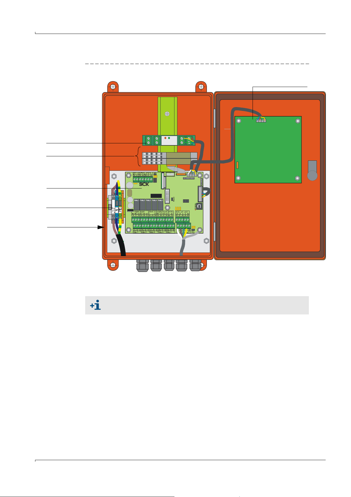
Assembly and Installation
Display module option
I/O module option
Power supply unit
(behind connection
board)
Terminals for power
supply
Processor board
Option
Interface module
3.3.6 Connecting the control unit MCU
Fig. 68 Component layout in the MCU (without cooling air supply, with options)
Subject to change w ithout notice
Necessary work
Connect the connection cable as shown in Fig. 73.
We recommend using a bus wiring configuration when the distance between
the sender/receiver units and the control unit is large.
Connect the cables for status signals (operation/malfunction, limit value, warning,
maintenance, check cycle), analog output, analog and digital inputs according to the
requirements.
Connect mains cable to terminals L1, N, PE (
Fig. 68).
Close off unused cable ducts with dummy plugs.
FLOWSIC100 · Operating Instructions · 8012513/YSA5/V 2-1/2016-07 · © SICK Engineering GmbH 97
Page 98

3.3.7 Connecting the control unit in a 19" housing
Terminal connection for power supply 90 - 250 VAC
Terminal connection for wiring by customer
Fig. 69 Connections on the MCU as 19" version
Assembly and Installation
Function Connection Terminal No.
Output relay 1 (operation/malfunction) com 1
1)
n.c.
n.o.
2)
2
3
Output relay 2 (maintenance) com 4
1)
n.c.
n.o.
2)
5
6
Output relay 3 (check cycle) com 7
1)
n.c.
n.o.
2)
8
9
Output relay 4 (maintenance request) com 10
1)
n.c.
n.o.
2)
11
12
Output relay 5 (limit value) com 13
1)
n.c.
n.o.
2)
14
15
Digital input d in 1 16
d in 2 17
gnd 18
d in 3 19
d in 4 20
gnd 21
Analog output + 22
-23
gnd 24
Analog input a in 1 25
gnd 26
a in 2 27
gnd 28
Subject to change w ithout notice
98 FLOWSIC100 · Operating Instructions · 8012513/YSA5/V2-1/2016-07 · © SICK Engineering GmbH
Page 99

Assembly and Installation
Function Connection Terminal No.
Master sender/receiver unit (unit 1) connections +24 31
-24 32
RS485 A 33
RS485 B 34
scr. 35
Master sender/receiver unit (unit 2) connections +24 36
-24 37
A38
B39
scr. 40
Input voltage supply 24V DC
3)
24 V 41
gnd 42
Output voltage supply 24 V DC
3)
24 V 43
gnd 44
Input 30 V electr. isolated + 45
-46
RS232/485
3)
tx/A 51
rx/B 52
gnd 53
Interface 1 A 71
B72
gnd 73
+Us 74
-Us 75
gnd 76
imp+ 77
imp- 78
res 1 79
res 2 80
1)
:Closed in current-free state (normal closed)
2)
:Open in current-free state (normal opened)
3)
:Only use after agreement with manufacturer
Subject to change w ithout notice
FLOWSIC100 · Operating Instructions · 8012513/YSA5/V 2-1/2016-07 · © SICK Engineering GmbH 99
Page 100

Fitting and connecting optional I/O modules
SICK
M
ULTI CONTROL UNIT
POWER
FAILURE
MAINTENANCE
REQUEST
INTERFACE-MODULE
I/O-MODULE
POWER
ERROR
TxD RxD
Slots for optional I/O modules
8
7
65 1
2
3
Slot
4
Slot for interface module option
101 a
102 b
103 c
104 d
105 a
106 b
107 c
108 d
109 -gnd
110 scr
101 a
102 b
103 c
104 d
105 a
106 b
107 c
108 d
109 -gnd
110 scr
+
+
+
+
-
-
-
-
AO (2x)
AI (2x)
Connect the optional analog and digital modules to the slots on the module carrier as from
slot 1 next to each other in the sequence AO
not present, the next one follows according to the specified sequence.
Fig. 70 Slots for optional modules
Connection is made to terminals 101 - 180 on the backplane.
The following shows the I/O module connection for slot 1 as an example.
Connect the I/O modules to slots 2 -8 in the same manner.
– Analog module connection
Assembly and Installation
AI DO DI. If single module types are
Fig. 71 Analog module on slot 1 (terminals 101 - 110)
Subject to change w ithout notice
100 FLOWSIC100 · Operating Instructions · 8012513/YSA5/V2-1/2016-07 · © SICK Engineering GmbH
 Loading...