

Page 1

O P E R A T I N G I N S T R U C T I O N S
Flexi Soft Modular Safety Controller
Hardware
Page 2
Described product
F
lexi Soft Modular Safety Controller
Hardware
Manufacturer
SIC
K AG
Erwin-Sick-Str. 1
79183 Waldkirch
Germany
Legal information
his work is protected by copyright. Any rights derived from the copyright shall be
T
reserved for SICK AG. Reproduction of this document or parts of this document is only
permissible within the limits of the legal determination of Copyright Law. Any modifica‐
tion, abridgment or translation of this document is prohibited without the express writ‐
ten permission of SICK AG.
The trademarks stated in this document are the property of their respective owner.
© SICK AG. All rights reserved.
Original document
T
his document is an original document of SICK AG.
2
O PE R AT I NG IN S TR U CT I ON S | Flexi Soft Modular Safety Controller 8012478/15UF/2019-10-31 | SICK
Subject to change without notice
Page 3

Contents
CONTENTS
1 About this document........................................................................ 7
1.1 Purpose of this document........................................................................ 7
1.2 Scope......................................................................................................... 8
1.3 Information depth..................................................................................... 9
1.4 Target group.............................................................................................. 9
1.5 Further information................................................................................... 9
1.6 Symbols and document conventions...................................................... 9
2 On safety............................................................................................. 11
2.1 General safety notes................................................................................ 11
2.2 Intended use............................................................................................. 11
2.3 Requirements for the qualification of personnel.................................... 12
3 Product description........................................................................... 13
3.1 System characteristics............................................................................. 13
3.2 Version, compatibility, and features........................................................ 14
3.3 Construction and function........................................................................ 16
3.4 Modules..................................................................................................... 18
3.4.1 FX3-CPU0 main module.......................................................... 19
3.4.2 FX3-CPU1 main module.......................................................... 19
3.4.3 FX3-CPU2 main module.......................................................... 20
3.4.4 FX3-CPU3 main module.......................................................... 21
3.4.5 FX3-MPL0 and FX3-MPL1 system plugs................................ 23
3.4.6 FX3-XTIO I/O module............................................................... 23
3.4.7 FX3-XTDI I/O module............................................................... 27
3.4.8 FX3-XTDS I/O module.............................................................. 29
3.4.9 FX0-STIO I/O module............................................................... 31
3.4.10 Drive Monitor FX3-MOC0......................................................... 33
3.4.11 Drive Monitor FX3-MOC1......................................................... 36
3.4.12 FX3-ANA0 analog input module.............................................. 39
3.4.13 UE410-2RO/UE410-4RO relay modules................................ 41
3.5 Interfaces.................................................................................................. 43
3.5.1 RS-232..................................................................................... 43
3.5.2 USB........................................................................................... 44
3.5.3 Enhanced Function Interface (EFI)......................................... 44
3.6 Special functions...................................................................................... 45
3.6.1 Flexi Link................................................................................... 45
3.6.2 Flexi Line.................................................................................. 46
3.6.3 Muting....................................................................................... 47
3.6.4 Automatic configuration recovery (ACR)................................. 48
4 Mounting............................................................................................. 49
5 Electrical installation........................................................................ 51
8012478/15UF/2019-10-31 | SICK O P ER A TI N G I NS T RU C TI O NS | Flexi Soft Modular Safety Controller
Subject to change without notice
3
Page 4

CONTENTS
5.1 Requirements to be met by the electrical installation........................... 51
5.2 Description of the terminals.................................................................... 53
5.2.1 FX3-CPU0 main module.......................................................... 53
5.2.2 FX3-CPU1 and FX3-CPU2 main modules............................... 54
5.2.3 FX3-CPU3 main module.......................................................... 55
5.2.4 FX3-XTIO I/O module............................................................... 56
5.2.5 FX3-XTDI I/O module............................................................... 57
5.2.6 FX3-XTDS I/O module.............................................................. 58
5.2.7 FX0-STIO I/O module............................................................... 59
5.2.8 Drive Monitor FX3-MOCx......................................................... 59
5.2.9 FX3-EBX1, FX3-EBX3, and FX3-EBX4 encoder/motor feed‐
bac
k connection boxes............................................................ 60
5.2.10 Encoder connection cables..................................................... 69
5.2.11 FX3-ANA0 analog input module.............................................. 72
5.2.12 UE410-2RO and UE410-4RO relay modules......................... 72
5.3 Wiring for the power supply to a Flexi Soft system................................. 74
5.4 Connection of devices.............................................................................. 74
5.4.1 Safety command devices and electro-mechanical safety
switches.................................................................................... 76
5.4.2 Non-contact safety switches................................................... 82
5.4.3 Testable single-beam photoelectric safety switches............. 83
5.4.4 Electro-sensitive protective devices....................................... 87
5.4.5 Safe outputs Q1 to Q4............................................................. 87
5.4.6 Connection of EFI-enabled devices........................................ 88
5.4.7 Connection of a Pro-face HMI................................................. 89
5.4.8 Connection of encoders.......................................................... 89
5.4.9 Connecting analog sensors..................................................... 94
5.4.10 Connection of a Flexi Link system.......................................... 96
5.4.11 Connecting a Flexi Line system............................................... 98
5.4.12 EMC measures for Flexi Link and Flexi Line........................... 99
6 Configuration..................................................................................... 100
7 Commissioning.................................................................................. 102
7.1 Overall acceptance of the application..................................................... 102
7.2 Checks before initial commissioning....................................................... 102
8 Operation............................................................................................ 104
8.1 Status messages on the FX3-CPUx main module.................................. 104
8.2 Status messages for the FX3-XTIO I/O module...................................... 105
8.3 Status messages for the FX3-XTDI I/O module...................................... 106
8.4 Status messages for the FX3-XTDS I/O module..................................... 107
8.5 Status messages for the FX0-STIO I/O module...................................... 108
8.6 Status signals of the FX3-ANA0 analog input module........................... 109
8.7 Status messages of the Drive Monitor FX3-MOCx.................................. 110
8.8 Status messages of the UE410-2RO and UE410-4RO relay modules.. 111
4
O PE R AT I NG IN S TR U CT I ON S | Flexi Soft Modular Safety Controller 8012478/15UF/2019-10-31 | SICK
Subject to change without notice
Page 5

CONTENTS
9 Maintenance...................................................................................... 112
9.1 Regular thorough check of the safety function by qualified safety per‐
l........................................................................................................ 112
sonne
9.2 Device replacement.................................................................................. 112
10 Diagnostics......................................................................................... 114
10.1 Response to errors................................................................................... 114
10.2 Error states................................................................................................ 114
10.3 Error displays shown by status LEDs, error messages, and trou‐
bleshooting measures.............................................................................. 115
10.4 Error history............................................................................................... 123
10.5 SICK support............................................................................................. 123
11 Decommissioning............................................................................. 124
11.1 Disassembling the modules.................................................................... 124
11.2 Disposal..................................................................................................... 125
11.3 Separation of materials............................................................................ 125
12 Technical data....................................................................................126
12.1 Minimum switch-off time.......................................................................... 126
12.2 Maximum response time of the Flexi Soft system................................. 126
12.2.1 Calculation of the response time............................................ 128
12.3 Data sheet................................................................................................. 135
12.3.1 Main modules FX3-CPU0, FX3-CPU1, FX3-CPU2, and FX3-
CPU3......................................................................................... 135
12.3.2 FX3-XTIO I/O module............................................................... 137
12.3.3 FX3-XTDI I/O module............................................................... 142
12.3.4 FX3-XTDS I/O module.............................................................. 145
12.3.5 FX0-STIO I/O module............................................................... 148
12.3.6 FX3-ANA0 analog input module.............................................. 149
12.3.7 Drive Monitor FX3-MOC0......................................................... 151
12.3.8 Drive Monitor FX3-MOC1......................................................... 157
12.3.9 FX3-EBX1, FX3-EBX3, and FX3-EBX4 for FX3-MOCx
encoder/motor feedback connection boxes.......................... 163
12.3.10 UE410-2RO/UE410-4RO relay modules................................ 165
12.3.11 Diode module DM8-A4K......................................................... 171
12.4 Dimensioned drawings............................................................................. 172
12.4.1 FX3-CPUx main modules with system plug............................ 172
12.4.2 FX3-XTIO, FX3-XTDI, FX3-XTDS, and FX0-STIO I/O modules,
UE410-2RO and UE410-4RO relay modules......................... 173
12.4.3 FX3-ANA0 analog input module.............................................. 174
12.4.4 Drive Monitor FX3-MOCx......................................................... 175
12.4.5 FX3-EBX1, FX3-EBX3, and FX3-EBX4 encoder/motor feed‐
back connection boxes............................................................ 176
12.4.6 Diode module DM8-A4K......................................................... 179
13 Ordering information........................................................................ 180
8012478/15UF/2019-10-31 | SICK O P ER A TI N G I NS T RU C TI O NS | Flexi Soft Modular Safety Controller
Subject to change without notice
5
Page 6

CONTENTS
13.1 System plugs and modules...................................................................... 180
13.2 Accessories............................................................................................... 182
14 List of abbreviations..........................................................................185
15 Appendix............................................................................................. 186
15.1 Compliance with EU directives................................................................. 186
15.2 Checklist for the manufacturer................................................................ 187
16 List of figures..................................................................................... 188
17 List of tables....................................................................................... 190
6
O PE R AT I NG IN S TR U CT I ON S | Flexi Soft Modular Safety Controller 8012478/15UF/2019-10-31 | SICK
Subject to change without notice
Page 7

ABOUT THIS DOCUMENT 1
1 About this document
1.1 Purpose of this document
These operating instructions contain the information required during the life cycle of the
lexi Soft modular safety controller.
F
These operating instructions are to be made available to all those who work with the
Flexi Soft modular safety controller.
For the Flexi Soft system, there are operating instructions and mounting instructions, each covering clearly defined
f
ields of application.
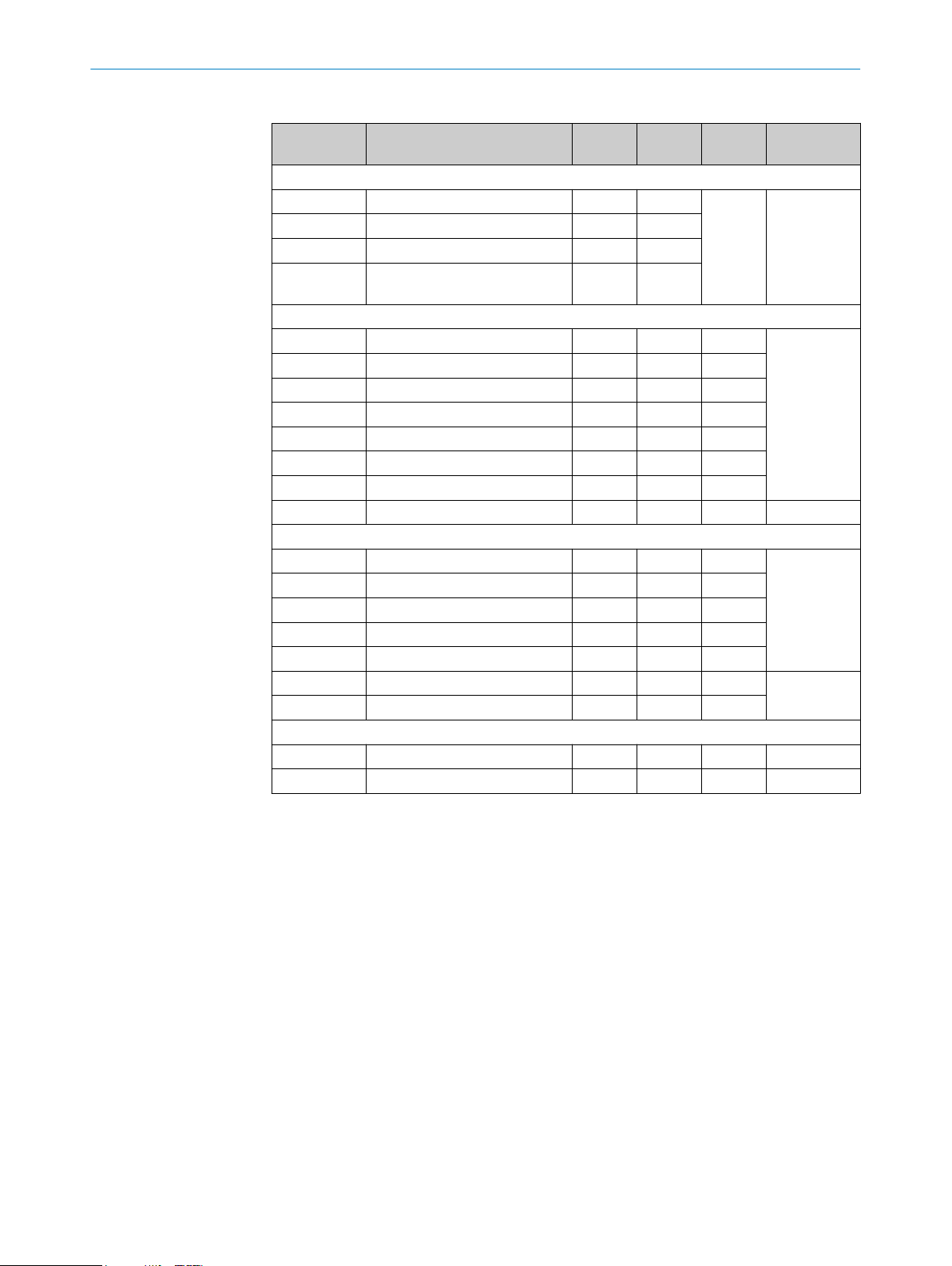
Table 1: Overview of the Flexi Soft documentation
Document type Title Contents Purpose Part number
Operating instruc‐
ions
t
Operating instruc‐
tions
Operating instruc‐
tions
Operating instruc‐
ions
t
Operating instruc‐
tions
Operating instruc‐
tions
Flexi Soft Modular
Safety Controller
Hardware
Flexi Soft in the
Flexi Soft Designer
Configuration software
Safety Designer
Configuration software
Flexi Soft in the
Safety Designer
Configuration software
Flexi Soft Gateways
Hardware
Flexi Soft Gateways in
Flexi Soft Designer
Configuration software
Description of the Flexi Soft
modules and their functions
Description of the softwarebased configuration of the
Flexi Soft safety controller
along with important diag‐
nostics functions and
detailed notes on identifying
and rectifying errors
Description of the installa‐
tion and general basic princi‐
ples of operation
Description of the softwarebased configuration of the
Flexi Soft safety controller
along with important diag‐
nostics functions and
detailed notes on identifying
and rectifying errors
Description of the Flexi Soft
gateways and their functions
Description of the softwarebased configuration of the
Flexi Soft gateway, informa‐
tion about data exchange in
networks as well as about
the status, planning, and
associated mapping
Instructions for technical
personnel working for the
machine manufacturer or
operator on the safe mount‐
ing, electrical installation,
and maintenance of the
Flexi Soft safety controller
Instructions for technical
personnel working for the
machine manufacturer or
operator on the safe configu‐
ration and commissioning,
as well as the safe opera‐
tion, of the Flexi Soft safety
controller
To provide technical person‐
nel working for the machine
manufacturer/operator with
instructions so that they can
use the Safety Designer con‐
figuration software
Instructions for technical
personnel working for the
machine manufacturer or
operator on the safe configu‐
ration and commissioning,
as well as the safe opera‐
tion, of the Flexi Soft safety
controller
To provide technical person‐
nel working for the machine
manufacturer/operator with
instructions so that they can
safely carry out the mount‐
ing, electrical installation,
and maintenance work for
the Flexi Soft gateways
To provide technical person‐
nel working for the machine
manufacturer/operator with
instructions so that they can
safely configure and com‐
mission the Flexi Soft gate‐
ways
8012999
8012998
8018178
8013926
8012662
8012483
8012478/15UF/2019-10-31 | SICK OP E RA T IN G I N ST R UC T IO N S | Flexi Soft Modular Safety Controller
Subject to change without notice
7
Page 8

BOUT THIS DOCUMENT
1 A
Document type Title Contents Purpose Part number
Operating instruc‐
t
ions
Operating instruc‐
tions
Operating instruc‐
tions
Operating instruc‐
tions
Mounting instruc‐
tions
Mounting instruc‐
tions
Flexi Soft Gateways in the
Safety Designer
Configuration software
Flexi Loop
safe series connection
Hardware
Flexi Loop in Safety Designer
Configuration software
Flexi Loop in the
Flexi Soft Designer
configuration software
Flexi Soft FX3-EBX3 and
FX3-EBX4 Encoder/Motor
Feedback Connection Boxes
Flexi Soft FX3-EBX1 Opti‐
mized Dual Encoder/Motor
Feedback Connection Box
Description of the softwarebased configuration of the
Flexi Soft gateway, informa‐
tion about data exchange in
networks as well as about
the status, planning, and
associated mapping
Description of the Flexi Loop
safe series connection and
its functions
Description of how to config‐
ure and set the parameters
for the Flexi Loop safe series
connection using software
Description of how to config‐
ure and set the parameters
for the Flexi Loop safe series
connection using software
Description of FX3-EBX3 and
FX3-EBX4 encoder/motor
feedback connection boxes
Description of the FX3-EBX1
optimized dual encoder/
motor feedback connection
box
To provide technical person‐
nel working for the machine
manufacturer/operator with
instructions so that they can
safely configure and com‐
mission the Flexi Soft gate‐
ways
To provide technical person‐
nel working for the machine
manufacturer/operator with
instructions so that they can
safely carry out the mount‐
ing, electrical installation,
and maintenance work for
the Flexi Loop safe series
connection
To provide technical person‐
nel working for the machine
manufacturer/operator with
instructions so that they can
safely configure and com‐
mission the Flexi Loop safe
series connection
To provide technical person‐
nel working for the machine
manufacturer/operator with
instructions so that they can
safely configure and com‐
mission the Flexi Loop safe
series connection
To provide technical person‐
nel working for the machine
manufacturer/operator with
instructions so that they can
safely carry out the mount‐
ing, electrical installation,
commissioning, and mainte‐
nance work for FX3-EBX3
and FX3-EBX4 encoder/
motor feedback connection
boxes
To provide technical person‐
nel working for the machine
manufacturer/operator with
instructions so that they can
safely carry out the mount‐
ing, electrical installation,
commissioning, and mainte‐
nance work for the FX3EBX1 optimized dual
encoder/motor feedback
connection box
8018170
8015834
8018174
8014521
8015600
8019030
1.2 Scope
8
O PE R AT I NG IN S TR U CT I ON S | Flexi Soft Modular Safety Controller 8012478/15UF/2019-10-31 | SICK
These operating instructions apply to all modules of the Flexi Soft safety controller with
he exception of the Flexi Soft gateway.
t
Subject to change without notice
Page 9

This document forms an integral part of SICK part number 8012999 (the “Flexi Soft
modular s
guages).
These operating instructions provide technical personnel of the machine manufacturer
or the machine operator instructions regarding the safe assembly, electrical installa‐
tion, commissioning, operation and maintenance of the Flexi Soft modular safety con‐
troller.
These operating instructions do not provide information on operating the machine in
which a safety controller is integrated. For information about this, refer to the operating
instructions of the specific machine.
1.3 Information depth
These operating instructions contain information about the modular Flexi Soft safety
cont
roller on the following topics:
ABOUT THIS DOCUMENT 1
afety controller hardware” in operating instructions in all available lan‐
Mount
•
Electrical installation
•
Hardware commissioning
•
The planning and use of SICK protective devices requires technical skills that are not
vered by this document.
co
The official and legal regulations for operating the Flexi Soft modular safety controller
must always be complied with.
1.4 Target group
These operating instructions are intended for planning engineers, developers, and oper‐
a
tors of plants and systems that are to be protected by means of a Flexi Soft modular
safety controller. They are also intended for people who integrate the Flexi Soft safety
controller into a machine, carry out its commissioning, or who are in charge of mainte‐
nance.
1.5 Further information
www.sick.com
T
he following information is available via the Internet:
The Flexi Soft operating instructions in various languages for viewing and printing
•
The Flexi Soft Designer configuration software
•
The Safety Designer configuration software
•
Configuration aids
•
Example applications
•
Data sheets
•
Product and application animations
•
CAD data for drawings and dimensional drawings
•
EDS, ESI, GSD, and GSDML files
•
Certificates (such as the EU declaration of conformity)
•
Guide for Safe Machinery (six steps to a safe machine)
•
ing
Fault diagnosis and troubleshooting
•
Ordering information
•
Conformity and approval
•
1.6 Symbols and document conventions
The following symbols are used in these operating instructions:
8012478/15UF/2019-10-31 | SICK OP E RA T IN G I N ST R UC T IO N S | Flexi Soft Modular Safety Controller
Subject to change without notice
9
Page 10
1 A
BOUT THIS DOCUMENT
Safety notes and other notes
DANGER
ates a situation presenting imminent danger, which will lead to death or serious
Indic
injuries if not prevented.
WARNING
Indic
ates a situation presenting possible danger, which may lead to death or serious
injuries if not prevented.
CAUTION
Indicates a situation presenting possible danger, which may lead to moderate or minor
injuries if not prevented.
NOTICE
ates a situation presenting possible danger, which may lead to property damage if
Indic
not prevented.
NOTE
Indic
ates useful tips and recommendations.
Instructions to action
he arrow denotes instructions to action. Read carefully and follow the instructions
T
b
for action.
LED symbols
These symbols indicate the status of an LED:
The LED is off.
o
The LED is flashing.
Ö
The LED is illuminated continuously.
O
10
O PE R AT I NG IN S TR U CT I ON S | Flexi Soft Modular Safety Controller 8012478/15UF/2019-10-31 | SICK
Subject to change without notice
Page 11
2 On safety
This chapter contains general safety information about the Flexi Soft modular safety
roller.
cont
More safety information about specific usage situations for the Flexi Soft modular
safety controller is provided in the respective chapters.
2.1 General safety notes
WARNING
proper mounting or use
Im
The target safety-related level may not be achieved in the event of non-compliance.
When mounting, installing, and using the Flexi Soft safety controller, remember to
b
observe all applicable standards and directives.
Observe the relevant national and international legal provisions for the installation
b
and use of the Flexi Soft safety controller, its commissioning, and technical inspec‐
tions repeated at regular intervals.
The manufacturer and operator of the machine on which the Flexi Soft safety con‐
b
troller is used are responsible for liaising with the relevant authorities about all
applicable safety regulations/rules and for ensuring compliance with these.
The notes, in particular the test notes, in these operating instructions (e.g. regard‐
b
ing use, mounting, installation, or integration into the machine controller) must
always be observed.
The thorough checks must be carried out by qualified safety personnel or specially
b
qualified and authorized personnel, and must be recorded and documented by a
third party to ensure that the tests can be reconstructed and retraced at any time.
ON SAFETY 2
2.2 Intended use
The Flexi Soft modular safety controller is an adjustable control for safety applications.
It is t
•
•
•
The safety level actually achieved is determined by the external wiring, how the wiring is
implemented, the configuration, the selection of command triggers, and how they are
arranged on the machine.
The Flexi Soft system satisfies the requirements for industrial areas in accordance with
t
only suitable for use in industrial environments.
The Flexi Soft system must only be used within the limits of the prescribed and speci‐
fied technical data and operating conditions at all times.
NOTICE
Incor
date any warranty from SICK; in addition, any responsibility and liability of SICK for dam‐
age and secondary damage caused by this is excluded.
The external power supply of the Flexi Soft modules must be capable of buffering brief
po
SELV power supply units are available as accessories from SICK.
o be used in accordance with the following standards:
IEC 61508 up to SIL3
EN 62061 up to SILCL3
EN ISO 13849-1 up to performance level e
he generic standard for emitted interference. Consequently, the Flexi Soft system is
rect use, improper modification or manipulation of the Flexi Soft system will invali‐
wer failures of 20 ms as specified in EN 60204-1, for example. Suitable PELV and
8012478/15UF/2019-10-31 | SICK OP E RA T IN G I N ST R UC T IO N S | Flexi Soft Modular Safety Controller
Subject to change without notice
11
Page 12

2 ON S
AFETY
UL/CSA applications:
If t
he product is being used in accordance with UL 508 or CSA C 22.2 No. 142, the fol‐
lowing conditions must also be met:
To protect the device’s 24-volt voltage supply, use a fuse with a maximum voltage
•
of 4 A and a minimum of 30 V DC in accordance with UL 248.
For wiring, only use copper wires with a temperature resistance of at least
•
60 °C / 75 °C, wire cross-section AWG 30–12 for screw terminals and/or
AWG 24–16 for spring terminals.
Tighten the screw terminals with a torque of 5 to 7 lb-in.
•
Only use the devices in an environment with maximum degree of contamination 2.
•
NOTE
he safety functions have not be evaluated by UL. Authorization is in accordance with
T
UL 508, general applications.
2.3 Requirements for the qualification of personnel
Only qualified safety personnel are permitted to configure, mount, connect, commis‐
sion, and maint
ain the Flexi Soft modular safety controller.
Project planning
A person who has expertise and experience in the selection and use of protective
devices on machines and is familiar with the relevant technical rules and national work
safety regulations is considered qualified for project planning.
Mechanical mounting and commissioning
A person who has expertise and experience in the relevant field and is sufficiently famil‐
iar with the application of the protective device on the machine to assess whether or
not it can be operated safely is considered qualified for mechanical installation and
commissioning.
Electrical installation
A person who has expertise and experience in the relevant field and is sufficiently famil‐
iar with the application of the protective device on the machine to assess whether or
not it can be operated safely is considered qualified for electrical installation and com‐
missioning.
Configuration
A person who has expertise and experience in the relevant field and is sufficiently famil‐
iar with the application of the protective device on the machine to assess whether or
not it can be operated safely is considered qualified for configuration.
Operation and maintenance
12
A person who has expertise and experience in the relevant field, is familiar with the
application of the protective device on the machine, and has received instructions from
the operator in how to operate the machine is considered qualified for operation and
maintenance.
O PE R AT I NG IN S TR U CT I ON S | Flexi Soft Modular Safety Controller 8012478/15UF/2019-10-31 | SICK
Subject to change without notice
Page 13

3 Product description
This chapter provides information about the properties of the Flexi Soft system and
scribes its construction and operating principle.
de
3.1 System characteristics
Sensors and switching elements (e.g. light curtains, laser scanners, switches, sensors,
encoder
controller and are linked logically. The corresponding actuators of the machines or sys‐
tems can be switched off safely via the switching outputs of the safety controller.
The Flexi Soft system is distinguished by the following system characteristics:
•
•
•
•
•
•
•
•
•
•
•
s, emergency stop pushbutton) are connected to the Flexi Soft modular safety
Modular design: 1 main module, up to 2 different gateways, and up to 12 expan‐
sion modules
Up to 96 safe digital inputs
Up to 12 safe analog inputs
Up to 48 safe digital outputs or up to 96 non-safe digital outputs
Configurable
.Use of up to 255 logic and application-specific function blocks
Logic function blocks, including, e.g., AND, OR, NOT, XNOR, XOR
Application-specific function blocks including, e.g., emergency stop, two-hand,
muting, presses, ramp-down detection, operating mode selector switch, reset,
restart
Can be integrated into different networks with gateways (EtherNet/IP™, Modbus
TCP, PROFINET IO, PROFIBUS DP, DeviceNet, CANopen and EtherCAT)
Safe gateway for EFI-pro
2 EFI interfaces on FX3-CPU1, FX3-CPU2, and FX3-CPU3 main modules (see "FX3-
CPU1 main module", page 19)
PRODUCT DESCRIPTION 3
1)
2)
The Flexi Soft Designer and Safety Designer configuration softwares are available for
configuration of the control tasks.
NOTE
T
he available range of performance of the Flexi Soft systems depends on the configura‐
tion software used, see "Version, compatibility, and features", page 14.
You will find the configuration software on the Internet: www
1)
The number of expansion modules is limited by the capacity of the FLEXBUS+ backplane bus. A Drive Monitor (FX3-MOCx) requires twice
the bus capacity of the other expansion modules. Therefore, each FX3-MOCx reduces the maximum possible number of expansion mod‐
ules that can be used by two.
2)
Each FX3-ANA0 expansion module provides two analog inputs, which are combined to form one safe channel. An FX3-ANA0 can there‐
fore safely detect an analog process variable using two sensors.
.sick.com
8012478/15UF/2019-10-31 | SICK OP E RA T IN G I N ST R UC T IO N S | Flexi Soft Modular Safety Controller
Subject to change without notice
13
Page 14

3 PRODUCT DESCRIPTION
3.2 Version, compatibility, and features
There are different firmware versions and function packages (so-called “Steps”) for the
lexi Soft product family that permit realization of the different functions. This section
F
provides an overview of which firmware version, which function package and/or which
version of the Flexi Soft Designer configuration software or Safety Designer configura‐
tion software is needed to use a certain function or a certain device.
Table 2: Modules, firmware versions, and software versions you will need
Necessary module with firmware
fr
om version
Function blocks and logic
Offline simulation of logic Unrestricted V1.2.0 V1.6.x
Import and export of partial applications Unrestricted V1.3.0 V1.6.x
Automatic circuit diagrams Unrestricted V1.3.0 V1.6.x
Central tag name editor Unrestricted V1.3.0 V1.6.x
Documentation for function blocks of main mod‐
s in logic editor
ule
Matrix of input and output connections Unrestricted V1.3.0 V1.6.x
Invertible inputs for the function blocks AND, OR,
RS Flip-Flop and Routing n:n
Function block for ramp-down detection FX3-CPUx V1.11.0 (Step 1.xx) V1.3.0 V1.6.x
Function blocks for configurable switch-on delay
and conf
Speed to Bool function block FX3-MOC0 V1.10.0 V1.7.0 V1.6.x
Motion Status to Bool function block FX3-MOC0 V1.10.0 V1.7.0 V1.6.x
Verification possible even without identical hard‐
w
Status input data and status output data in logic FX3-CPUx V2.00.0 (Step 2.xx)
Easy applications for FX3-MOC0 FX3-MOC0 V1.10.0 V1.7.1 N. a.
Special functions
Two S3000 safety laser scanners at one EFI
int
Flexi Link FX3-CPU1 V2.00.0 (Step 2.xx) V1.3.0 N. a.
Flexi Loop FX3-CPUx V3.00.0 (Step 3.xx)
Flexi Line FX3-CPU3 V3.00.0 (Step 3.xx) V1.6.0 N. a.
Automatic configuration of connected EFIenabled s
recovery)
Deactivation of test signals Q1 to Q4 on the FX3X
Fast shut-off with bypass at FX3-XTIO FX3-CPUx and FX3-XTIO, each
Multiple safety mats at FX3-XTIO/FX3-XTDI FX3-XTIO or FX3-XTDI, each V1.13.0 V1.3.0 V1.6.x
Data recorder FX3-CPUx V2.00.0 (Step 2.xx) V1.5.0 V1.6.x
igurable switch-off delay
are
erface
afety sensors (automatic configuration
TIO possible
Unrestricted V1.3.0 N. a.
FX3-CPUx V2.00.0 (Step 2.xx) V1.3.0 V1.6.x
FX3-CPUx V2.00.0 (Step 2.xx) V1.3.0 V1.6.x
FX3-CPUx V2.00.0 (Step 2.xx) V1.3.0 V1.6.x
and FX3-XTIO, FX3-XTDI, or FX3XTDS, each V2.00.0 (Step 2.xx)
FX3-CPU1 V1.00.0 V1.2.2 N. a.
and FX3-XTIO, FX3-XTDI, or FX3XTDS, each V3.00.0 (Step 3.xx)
FX3-CPU2 V3.00.0 (Step 3.xx) V1.5.0
FX3-XTIO V2.00.0 (Step 2.xx) V1.3.0 V1.6.x
V2.00.0 (Step 2.xx)
Available from
Flexi Soft
Designer
V1.3.0 V1.6.x
V1.6.0 V1.8.0
(FX3-CPU2)
V1.6.0
(FX3-CPU3)
V1.3.0 V1.6.x
Available from
Safety Designer
N. a.
1)
14
O PE R AT I NG IN S TR U CT I ON S | Flexi Soft Modular Safety Controller 8012478/15UF/2019-10-31 | SICK
Subject to change without notice
Page 15

PRODUCT DESCRIPTION 3
Necessary module with firmware
fr
om version
Available from
Flexi Soft
Available from
Safety Designer
Designer
Extended cross-circuit detection time for the
FX3-XTIO V3.00.0 (Step 3.xx) V1.6.0 V1.6.x
switching of increased capacitive loads at FX3XTIO
Configurable filter time for in/out filters and
in filters at inputs I1 to I8 at FX3-XTIO/FX3-
out/
FX3-XTIO, FX3-XTDI, or FX3-XTDS,
each V3.00.0 (Step 3.xx)
V1.6.0 V1.6.x
XTDI/FX3-XTDS
Optimization of logic execution time FX3-CPUx V4.00.0 (Step 4.xx) V1.7.1 V1.6.x
Automated download No limitation V1.9.1 n.a.
Devices
FX3-CPU0 No limitation V1.2.0 V1.6.x
FX3-CPU1 No limitation V1.2.0 N. a.
FX3-CPU2 No limitation V1.2.0 N. a.
FX3-CPU3 No limitation V1.2.0 N. a.
FX3-XTIO No limitation V1.2.0 V1.6.x
FX3-XTDI No limitation V1.2.0 V1.6.x
Gateways for PROFINET IO, Modbus TCP and Eth‐
et/IP™
erN
FX3-CPUx V1.11.0 (Step 1.xx) V1.2.0 V1.6.x
CC-Link gateway FX3-CPUx V1.11.0 (Step 1.xx) V1.3.0 N. a.
CANopen gateway FX3-CPUx V1.11.0 (Step 1.xx) V1.3.0 V1.6.x
EtherCAT gateway FX3-CPUx V2.00.0 (Step 2.xx) V1.3.0 V1.6.x
EFI-pro gateway FX3-CPUx V4.00.0 (Step 4.xx) N. a. V1.6.x
Speed Monitor MOC3SA Unrestricted V1.3.0 V1.6.x
FX3-MOC0 FX3-CPUx V2.50.0 V1.5.0 N. a.
FX3-MOC1 FX3-CPUx V2.50.0 V1.8.0 V1.6.x
FX3-XTDS Unrestricted V1.6.0 V1.6.x
FX0-STIO Unrestricted V1.6.0 V1.6.x
FX3-ANA0 FX3-CPUx V4.00.0 (Step 4.xx) V1.8.0 V1.7.0
Conformities
RoHS conformity FX3-XTIO FX3-XTIO V1.01.0 – –
1)
N. a. = Not available
2)
All other modules as from market introduction.
8012478/15UF/2019-10-31 | SICK OP E RA T IN G I N ST R UC T IO N S | Flexi Soft Modular Safety Controller
Subject to change without notice
15
Page 16

3 P
RODUCT DESCRIPTION
NOTE
e recent modules are backward compatible so that each module can be
Mor
•
replaced by one with a higher firmware version.
Flexi Soft Designer Version ≥ V1.4.0 can also be used to configure devices with a
•
later version of the firmware, even if Flexi Soft Designer does not yet recognize the
new firmware. In such cases, the user will only be able to access the function
packages (Step 1.xx, Step 2.xx, Step 3.xx, or Step 4.xx) that are supported by the
available version of Flexi Soft Designer.
A corresponding new version of the configuration software is needed in order to
•
use the full functional scope of modules with a later firmware version.
The configuration software is not upwards-compatible. In other words, a project
•
created with a more recent version of the configuration software cannot be
opened with an older version.
The function package (Step 1.xx, Step 2.xx, Step 3.xx, or Step 4.xx) must be
•
selected in the hardware configuration menu of the configuration software. The
availability of a desired function package in the configuration software is shown in
the table.
To use the Step N.xx function package, the relevant module must have a minimum
•
firmware version of VN.00.0. If you try to transfer a configuration in a module with
a lower firmware version, an error message is displayed.
The hardware version of the Flexi Soft modules can be seen in the hardware con‐
•
figuration of the configuration software in online status or in the report if the sys‐
tem was previously online.
You will find the firmware version of the Flexi Soft modules on the type label of the
•
Flexi Soft modules in the firmware version field.
The date of manufacture of a device can be found in the S/N field on the type
•
label in the format yywwnnnn (yy = year, ww = calendar week, nnnn = sequential
serial number in the calendar week).
The version of the configuration software can be found by selecting Info in the
•
Extras menu.
The latest version of the configuration software can be found on the Internet at
•
www.sick.com.
3.3 Construction and function
System construction
lexi Soft system consists of the following modules:
A F
1 Flexi Soft system plug
•
1 Flexi Soft main module
•
Up to 2 Flexi Soft gateways
•
Up to 12 Flexi Soft expansion modules
•
In addition, up to 8 UE410-2RO relay modules and/or up to 4 UE410-4RO relay
•
modules (i.e., a maximum of 16 safe relay outputs)
NOTE
Onl
y those modules listed here can be connected to a Flexi Soft system; other modules
are not permitted.
3)
he number of expansion modules is limited by the capacity of the FLEXBUS+ backplane bus. A Drive Monitor (FX3-MOCx) requires twice
T
the bus capacity of the other expansion modules. Therefore, each FX3-MOCx reduces the maximum possible number of expansion mod‐
ules that can be used by two.
16
O PE R AT I NG IN S TR U CT I ON S | Flexi Soft Modular Safety Controller 8012478/15UF/2019-10-31 | SICK
3)
Subject to change without notice
Page 17
PRODUCT DESCRIPTION 3
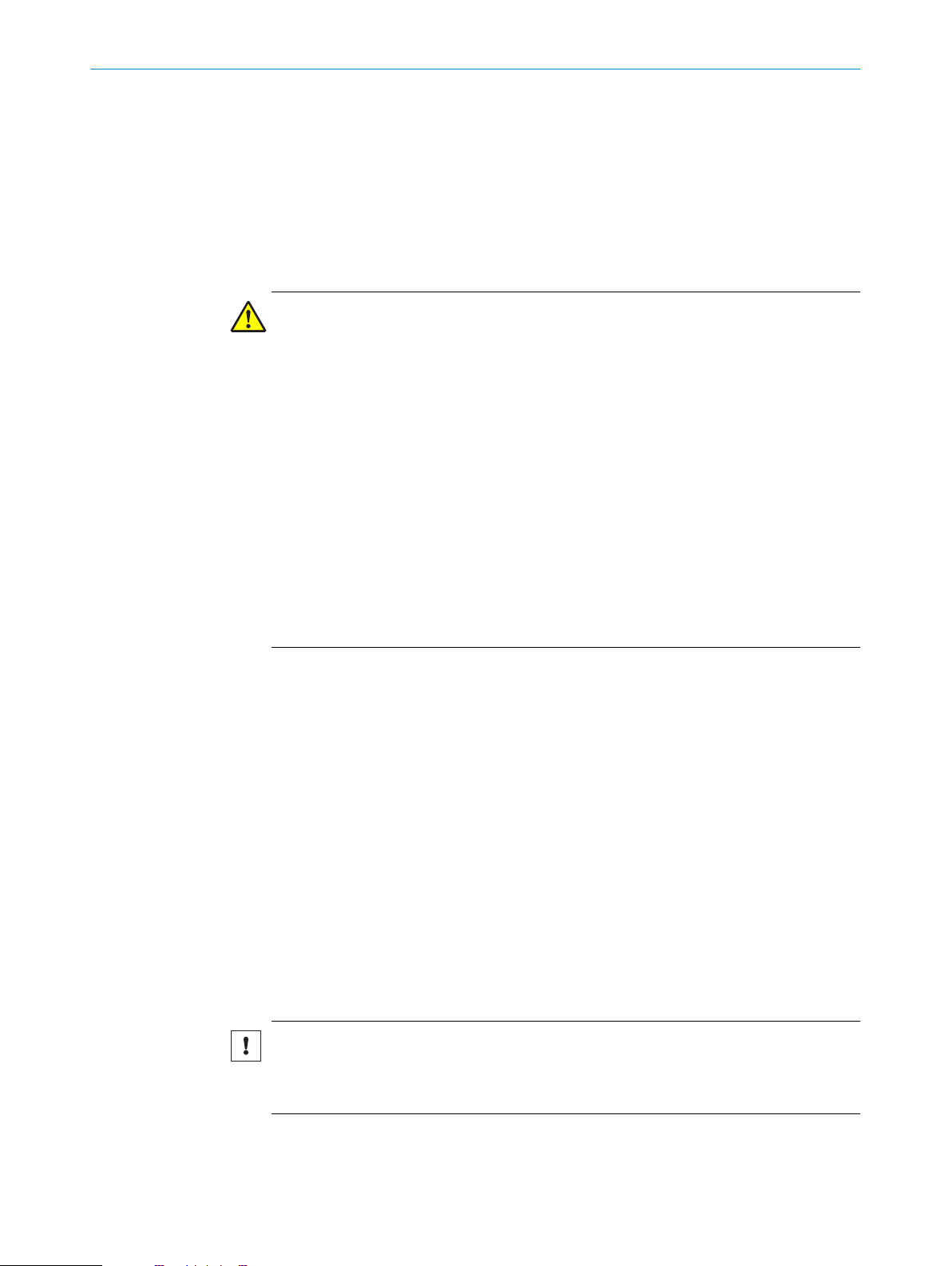
Figure 1: Example minimum construction of the Flexi Soft system with FX3-CPU0 and FX3-XTDI or
FX3-
CPU1 and FX3-XTIO
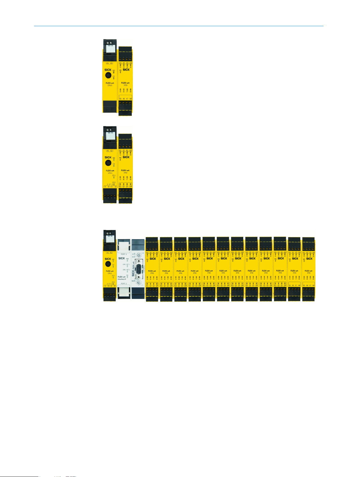
Figure 2: Maximum structure of the Flexi Soft system (without relay modules)
8012478/15UF/2019-10-31 | SICK OP E RA T IN G I N ST R UC T IO N S | Flexi Soft Modular Safety Controller
Subject to change without notice
17
Page 18
3 PRODUCT DESCRIPTION
Table 3: Overview of modules
Model Type Inputs Outputs Function
Main modules
FX3-CPU0 Main module – –
FX3-CPU1 Main module with EFI 4
FX3-CPU2 Main module with EFI and ACR 4
FX3-CPU3 Main module with EFI and ACR
Gateways
FX0-GENT EtherNet/IP™ gateway 2
FX0-GMOD Modbus TCP gateway 2
FX0-GPNT PROFINET IO gateway 2
FX0-GETC EtherCAT gateway 2
FX0-GPRO PROFIBUS DP gateway 1
FX0-GCAN CANopen gateway 1
FX0-GDEV DeviceNet gateway 1
FX3-GEPR EFI-pro gateway 2
Expansion modules
FX3-XTIO I/O module 8 4 –
FX3-XTDI I/O module 8 – –
FX3-XTDS I/O module 8 4–6
FX0-STIO I/O module 6–8
FX3-ANA0 Analog input module 2
FX3-MOC0 Drive Monitor – – 10 6
FX3-MOC1 Drive Monitor – – 25
Relay modules
UE410-2RO Relay module – 2 – 8
UE410-4RO Relay module – 4 – 4
1)
EFI connections.
2)
EFI and Flexi Line connections.
3)
RJ-45 female connectors.
4)
RS-485 female connector.
5)
Non-safe outputs. Test outputs XY1 and XY2 can be used as additional non-safe outputs.
6)
The FX0-STIO features 6 non-safe inputs and 6 non-safe outputs. In addition, connections IY7 and IY8
c
7)
Each FX3-ANA0 expansion module provides two analog inputs, which are combined to form one safe
channel. An FX3-ANA0 can therefore safely detect the size of an analog process using two sensors.
8)
Each FX3-MOCx module reduces the maximum possible number of expansion modules that can be used
by two.
9)
Maximum 16 safe relay outputs.
8
lexi Line
and F
an be used as non-safe inputs as well as non-safe outputs.
Max. number
bloc
ks
1)
1)
2)
3)
3)
3)
3)
4)
4)
4)
3)
6)
7)
–
–
255 1
–
– –
– –
– –
– –
– –
– –
– –
– – 1
6–8
5)
6)
–
–
– –
2
12
8)
9)
9)
3.4 Modules
18
O PE R AT I NG IN S TR U CT I ON S | Flexi Soft Modular Safety Controller 8012478/15UF/2019-10-31 | SICK
This chapter provides information about the properties and functions of the available
module
s and system components.
Subject to change without notice
Page 19

3.4.1 FX3-CPU0 main module
Description
T
he FX3-CPU0 main module is the CPU for the entire system. It is where all signals are
monitored and their logic is processed on the basis of the configuration stored in the
system plug. The system outputs are switched further to the processing of the signals.
The FLEXBUS+ internal bus provides the data interface.
NOTE
The FX3-CPU0 main module can only be operated together with the FX3-MPL0 system
plug.
PRODUCT DESCRIPTION 3
Figure 3: FX3-CPU0 main module
FX3-MPL0 system plug
1
RS-232 interface
2
MS LED (Module St
3
CV LED (Configuration Verified)
4
3.4.2 FX3-CPU1 main module
Description
T
he functions of the FX3-CPU1 main module are the same as those of the FX3-CPU0
main module.
Additionally, this module has 2 EFI interfaces. When EFI-enabled devices are con‐
nected, the following functions are supported:
Transfer configuration to the connected EFI-enabled devices
•
Import configuration from the connected EFI-enabled devices
•
Diagnose the connected EFI-enabled devices
•
Exchange process data between main module and EFI-enabled devices
•
Connect up to four FX3-CPU1 main modules to one Flexi-Link system (see "Flexi
•
Link", page 45)
More information about EFI interfaces: see "Enhanced Function Interface (EFI)",
page 44
atus)
NOTE
T
he FX3-CPU1 main module can only be operated together with the FX3-MPL0 system
plug.
8012478/15UF/2019-10-31 | SICK OP E RA T IN G I N ST R UC T IO N S | Flexi Soft Modular Safety Controller
Subject to change without notice
19
Page 20
3 PRODUCT DESCRIPTION
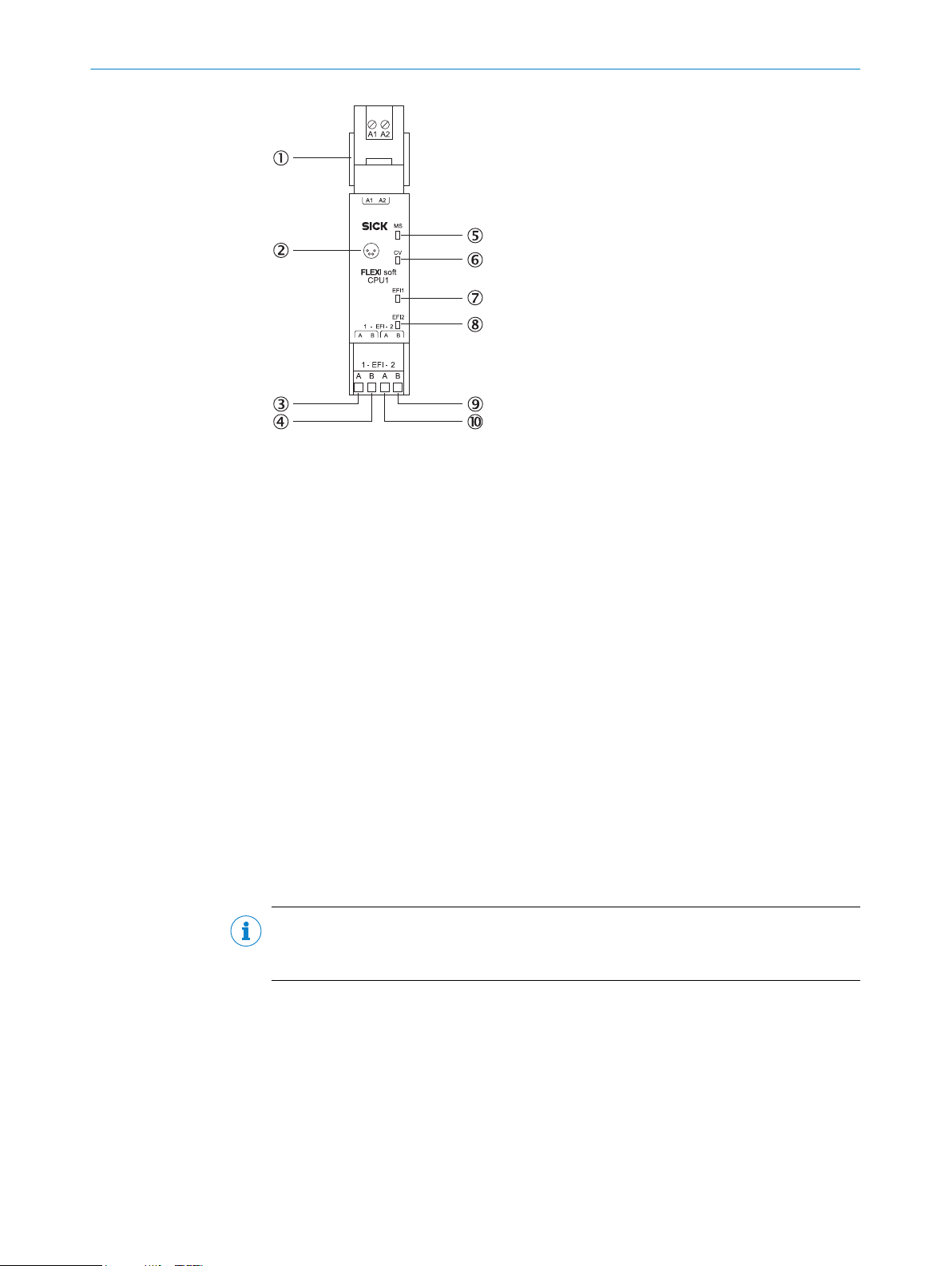
Figure 4: FX3-CPU1 main module
1
2
3
4
5
6
7
8
9
ß
FX3-MPL0 system plug
RS-232 interface
EFI1_A
EFI1_B
MS LED (Module Status)
CV LED (Configuration Verified)
EFI1 LED
EFI2 LED
EFI2_B
EFI2_A
3.4.3 FX3-CPU2 main module
Description
T
he functions of the FX3-CPU2 main module are the same as those of the FX3-CPU1
main module.
Furthermore, the FX3-CPU2 main module has an automated function for configuring
connected EFI-enabled devices (ACR). More information: see "Automatic configuration
recovery (ACR)", page 48 and the “Flexi Soft in the Flexi Soft Designer Configuration
Software” operating instructions.
NOTE
T
he FX3-CPU2 main module can only be operated together with the FX3-MPL1 system
plug.
20
O PE R AT I NG IN S TR U CT I ON S | Flexi Soft Modular Safety Controller 8012478/15UF/2019-10-31 | SICK
Subject to change without notice
Page 21
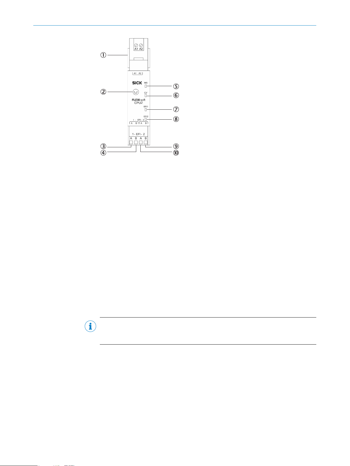
Figure 5: FX3-CPU2 main module
FX3-MPL1 system plug
1
RS-232 interface
2
EFI1_A
3
EFI1_B
4
MS LED (Module St
5
CV LED (Configuration Verified)
6
EFI1 LED
7
EFI2 LED
8
EFI2_B
9
EFI2_A
ß
atus)
PRODUCT DESCRIPTION 3
3.4.4 FX3-CPU3 main module
Description
T
he functions of the FX3-CPU3 main module are the same as those of the FX3-CPU2
main module.
This module also has a Flexi Line interface to support the safe networking of up to 32
Flexi Soft stations (see "Flexi Line", page 46).
NOTE
T
he FX3-CPU3 main module can only be operated together with the FX3-MPL1 system
plug.
8012478/15UF/2019-10-31 | SICK OP E RA T IN G I N ST R UC T IO N S | Flexi Soft Modular Safety Controller
Subject to change without notice
21
Page 22

3 PRODUCT DESCRIPTION
Figure 6: FX3-CPU3 main module
1
2
3
4
5
6
7
8
9
ß
à
á
â
ã
ä
FX3-MPL1 system plug
RS-232 interface
USB interface
Line_PRE_A (previous)
Line_PRE_B (previous)
EFI1_A
EFI1_B
MS LED (Module St
CV LED (Configuration Verified)
LINE LED
EFI1 and EFI2 LEDs
Line_NEXT_B (next)
Line_NEXT_A (next)
EFI2_B
EFI2_A
atus)
22
USB interface
T
he FX3-CPU3 main module has a USB interface which supports the following func‐
tions:
Transfer of the configuration from the configuration software to the system plug
•
Import of the configuration into the configuration software from the system plug
•
Diagnosis of the Flexi Soft safety controller in conjunction with the configuration
•
software
Table 4: USB interface on the FX3-CPU3 main module
USB version Connection type
2.0 Mini-B
O PE R AT I NG IN S TR U CT I ON S | Flexi Soft Modular Safety Controller 8012478/15UF/2019-10-31 | SICK
Subject to change without notice
Page 23

3.4.5 FX3-MPL0 and FX3-MPL1 system plugs
There is a system plug at each main module. The system configuration for the entire
F
lexi Soft system is stored only in the system plug. This is beneficial when replacing
modules, because it means that a full reconfiguration of the Flexi Soft system is not
required.
System plug variants
There are two system plug variants, each of which can only be used in conjunction with
certain main modules.
Table 5: System plug variants
System plug Terminal color Compatible main
FX3-MPL0 Black
FX3-MPL1 Yellow
module
FX3-
•
FX3-CPU1
•
FX3-CPU2
•
FX3-CPU3
•
s
CPU0
PRODUCT DESCRIPTION 3
Functions
Flexi Soft system power supply
•
Storage of system configuration
•
(without EFI-enabled devices)
Flexi Soft system power supply
•
Storage of system configuration
•
(with EFI-enabled devices)
Automated configuration of con‐
•
nected EFI-capable safety sen‐
sors (automated configuration
recovery)
NOTE
T
•
modules and gateways on the FLEXBUS+, and its inputs (I1 to I8) and test outputs
(X1 to X8 plus XY1 and XY2) is provided exclusively via the system plug. The power
for the outputs (Q1 to Q4, Y1 to Y6, and IY7 and IY8), on the other hand, is sup‐
plied separately.
The data saved in the system plug is retained even in the event of a power supply
•
failure.
Clearly and unambiguously mark all connections (connecting cables and plug con‐
•
nectors) on the safety controller to avoid mix-ups. The Flexi Soft system features
several connections of the same design. Therefore, you must make sure that no
unplugged connecting cables or plug connectors are accidentally connected to the
wrong connection point.
3.4.6 FX3-XTIO I/O module
Description
T
he FX3-XTIO module is an input/output expansion module with 8 safe inputs and
4 safe outputs. It has 2 test pulse generators, one for test output X1 and one for test
output X2.
The FX3-XTIO module supports the following functions:
Monitoring of the connected safety devices (see "Connection of devices",
•
page 74)
Forwarding of information at inputs I1 to I8 to the main module
•
Receipt of control signals from the main module and corresponding switching of
•
outputs
Fast shut-off: direct shutdown of the actuators connected to the module.
•
he electrical power supply for the main module, the internal logic of all expansion
8012478/15UF/2019-10-31 | SICK OP E RA T IN G I N ST R UC T IO N S | Flexi Soft Modular Safety Controller
Subject to change without notice
23
Page 24
RODUCT DESCRIPTION
3 P
This reduces the response time of the overall system. The response times of the
de
vices at the inputs and outputs are extended by 8 ms in order to shut down the
outputs. Run times on the FLEXBUS+ internal bus and the logic execution time are
not relevant in this case (see "Maximum response time of the Flexi Soft system",
page 126).
A
ctivation or deactivation of the test signals at outputs Q1 to Q4
•
The FX3-XTIO module cannot be operated alone; an FX3-CPUx main module is always
necessary.
Multiple FX3-XTIO modules can be used at the same time (see "Construction and func‐
tion", page 16).
The power supply to the internal logic and the test outputs is provided via the system
plug and the FLEXBUS+ internal bus.
The power supply to outputs Q1 to Q4 on the FX3-XTIO must be provided directly via
A1/A2 at the corresponding module.
WARNING
Ine
ffectiveness of the protective device due to unrecognized short-circuits between the
test pulse generators
The dangerous state may not be stopped or not be stopped in a timely manner in the
event of non-compliance.
Configure the test outputs of the Flexi Soft expansion modules with test gaps
b
≤ 4 ms and a test period ≥ 200 ms.
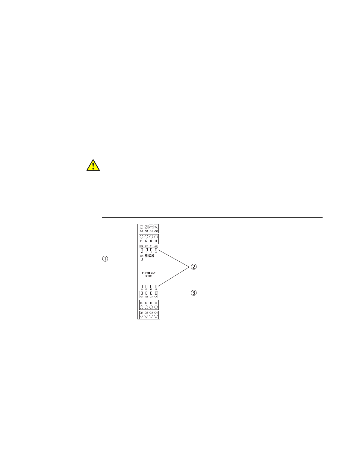
Figure 7: FX3-XTIO I/O module
MS LED (Module St
1
8 input LEDs
2
4 output LEDs
3
atus)
24
O PE R AT I NG IN S TR U CT I ON S | Flexi Soft Modular Safety Controller 8012478/15UF/2019-10-31 | SICK
Subject to change without notice
Page 25
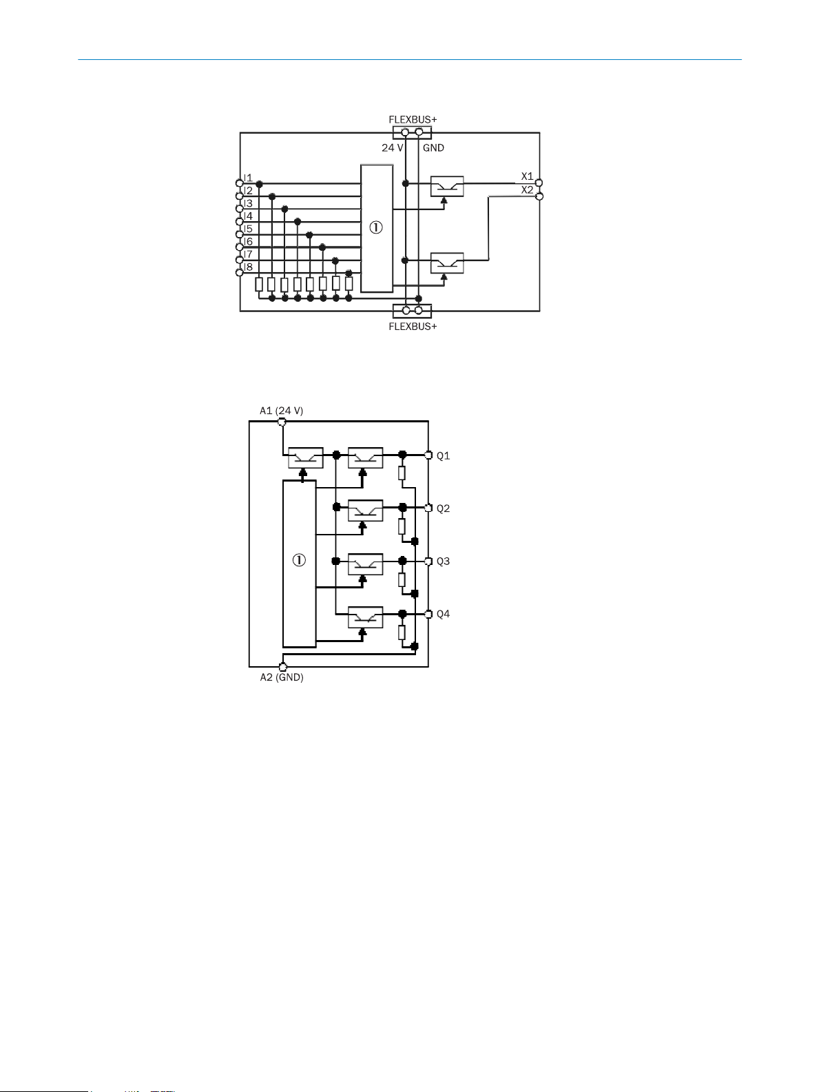
3.4.6.1 Internal structure
Figure 8: Internal structure of the FX3-XTIO – safe inputs and test outputs
1
PRODUCT DESCRIPTION 3
Internal logic
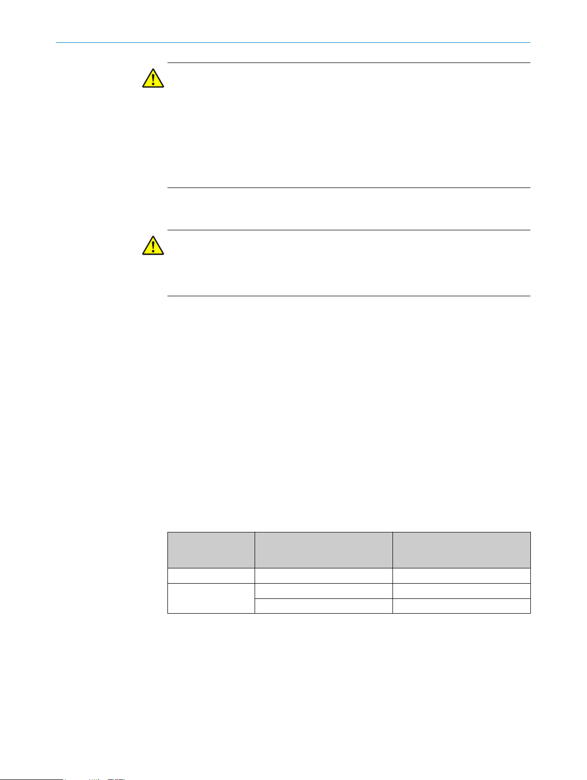
Figure 9: Internal structure of the FX3-XTIO – safe outputs
Internal logic
1
3.4.6.2 Deactivation of test signals at outputs Q1 to Q4 on the FX3-XTIO
With the FX3-XTIO Step ≥ 2.xx (firmware versions V2.00.0), it is possible to deactivate
t
he test pulses at one or more outputs of FX3-XTIO modules.
Deactivating the test pulses at one or more of the outputs (Q1 to Q4) of an FX3-XTIO
module reduces the safety parameters of all the outputs (Q1 to Q4) of the module con‐
cerned. If the test pulses are deactivated, a short-circuit cannot be recognized after
24 V if the output is high. Therefore, in the case of a recognized internal hardware error,
the switch-off capability of the other outputs can be impaired by the reverse current of
24 V via the output whose test pulse has been deactivated. This must be taken into
account to ensure that the application is in line with an appropriate risk analysis and
risk avoidance strategy.
8012478/15UF/2019-10-31 | SICK OP E RA T IN G I N ST R UC T IO N S | Flexi Soft Modular Safety Controller
Subject to change without notice
25
Page 26
RODUCT DESCRIPTION
3 P
WARNING
educed safety parameters by deactivating test pulses
R
The target safety-related level may not be achieved in the event of non-compliance.
If the test pulse is deactivated at one or several of the safe outputs Q1 to Q4, take the
following measures:
Use protected or separate cabling.
b
At least once a year, either switch off all outputs without test pulses simultane‐
b
ously for at least one second using the logic program of the main module or
restart the Flexi Soft system by switching off the voltage supply.
3.4.6.3 Extended error detection time for cross-circuits at outputs Q1 to Q4 on the FX3-XTIO for the switching
eased capacitive loads
of incr
WARNING
Ext
ended error recognition time due to switching of higher capacitive loads
The target safety-related level may not be achieved in the event of non-compliance.
Pay attention to the extended error recognition time.
b
With the FX3-XTIO Step ≥ 3.xx (firmware version V3.00.0), it is possible to configure an
xtended fault detection time for cross-circuits that affect outputs Q1 to Q4 of FX3-XTIO
e
modules.
This may be necessary to switch loads where the voltage at the load does not drop to
the Low level as quickly as expected, with the result that if the standard error detection
time is set, a cross-circuit error occurs immediately after switching off (change from
High to Low). Examples of such instances include:
Loads with a capacitance that is higher than the standard level permitted for the
•
output, such as the supply voltage of PLC output cards that require safety-related
switching.
For this application, the test signal for the input must also be deactivated (see
eactivation of test signals at outputs Q1 to Q4 on the FX3-XTIO", page 25).
"D
Safety-capable inputs on fail-safe PLCs generally also have capacitance at the
inputs.
Induc
•
tive loads which cause an overshoot in the positive voltage range after the
induction voltage has died down.
Table 6: Maximum permissible time until Low level is reached after output (Q1 to Q4) is deacti‐
vated
FX3-XTIO firmware
ersion
v
≤ V2.11.0 Not possible 3 ms
≥ V3.00.0 Deactivated 3 ms
Switching of increased capacitive
loads
Activated 43 ms
Maximum permissible time until
Low level (≤ 3.5 V) is reached after
output (Q1 to Q4) is deactivated
Once the output has been deactivated, the capacitance that exceeds the standard
v
alue permitted for the output must be discharged by the user until the Low level is
reached. If this condition is not met within the maximum permissible time, it results in a
cross-circuit fault at the corresponding output regardless of whether test pulses are
activated or deactivated for the output concerned.
26
O PE R AT I NG IN S TR U CT I ON S | Flexi Soft Modular Safety Controller 8012478/15UF/2019-10-31 | SICK
Subject to change without notice
Page 27
PRODUCT DESCRIPTION 3
WARNING
oss or impairment of the safety-related switch-off capability due to PLC output card
L
errors
The dangerous state may not be stopped or not be stopped in a timely manner in the
event of non-compliance.
Use a PLC output card that is suitable for safety-related deactivation of the outputs
b
by means of supply voltage switching.
Take suitable measures to prevent a cross-circuit, e.g., using protected cable lay‐
b
ing.
When using a buffer capacitor in the voltage supply of the PLC output card,
b
observe the possibly extended response time.
For information about this, see also the “Flexi Soft in the Flexi Soft Designer Configura‐
t
ion Software” and “Flexi Soft in the Safety Designer Configuration Software” operating
instructions.
3.4.6.4 Fault detection time and fault response time when using single-channel outputs on the FX3-XTIO
The fault detection time plus the fault response time of the FX3-XTIO depends on the
conf
iguration of the respective output.
In the case of an internal hardware fault, outputs (Q1 to Q4), which would normally be
on low, may switch off with a delay and/or may briefly switch to high until the fault has
been recognized and the fault reaction has been carried out.
WARNING
Ine
ffectiveness of the protective device due to brief switching to high for single-channel
outputs
The dangerous state may not be stopped or not be stopped in a timely manner in the
event of non-compliance.
The target safety-related level may not be achieved in the event of non-compliance.
For risk analysis and risk avoidance strategy, consider the following:
b
°
°
Table 7: Fault detection time and fault response time on the FX3-XTIO
FX3-XTIO firmware
v
ersion
≤ V2.11.0 Not possible ≤ 10 ms
≥ V3.00.0 Deactivated ≤ 10 ms
3.4.7 FX3-XTDI I/O module
Brief switching to high or delayed switching off of single-channel outputs
Fault detection time and fault response time
Switching higher capacitive loads Fault detection time + fault
response time
Enabled ≤ 50 ms
Description
T
he FX3-XTDI module is an input expansion module with 8 safe inputs. It has 2 test
pulse generators, one for test outputs X1, X3, X5 and X7 and one for test outputs X2,
X4, X6 and X8.
The FX3-XTDI module supports the following functions:
Monitoring of the connected safety devices (see "Connection of devices",
•
page 74)
Forwarding of information at inputs I1 to I8 to the main module
•
8012478/15UF/2019-10-31 | SICK OP E RA T IN G I N ST R UC T IO N S | Flexi Soft Modular Safety Controller
Subject to change without notice
27
Page 28
3 P
RODUCT DESCRIPTION
The FX3-XTDI module cannot be operated alone; an FX3-CPUx main module is always
nece
ssary.
Multiple FX3-XTDI modules can be used at the same time (see "Construction and func‐
tion", page 16).
The power supply to the internal logic and the test outputs is provided via the system
plug and the FLEXBUS+ internal bus.
WARNING
Ine
ffectiveness of the protective device due to unrecognized short-circuits between the
test pulse generators
The dangerous state may not be stopped or not be stopped in a timely manner in the
event of non-compliance.
Exclude short-circuits between the odd-numbered test outputs X1, X3, X5 and X7
b
through suitable wiring (e.g. separate routing, protected cables).
Exclude short-circuits between the even-numbered test outputs X2, X4, X6 and X8
b
through suitable wiring (e.g. separate routing, protected cables).
Configure the test outputs of the Flexi Soft expansion modules with test gaps
b
≤ 4 ms and a test period ≥ 200 ms.
28
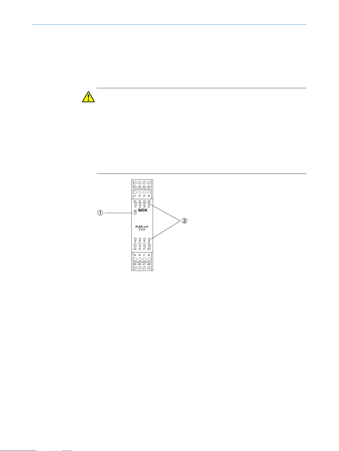
Figure 10: FX3-XTDI I/O module
MS LED (Module St
1
8 input LEDs
2
O PE R AT I NG IN S TR U CT I ON S | Flexi Soft Modular Safety Controller 8012478/15UF/2019-10-31 | SICK
atus)
Subject to change without notice
Page 29
3.4.7.1 Internal structure
Figure 11: Internal structure of the FX3-XTDI – safe inputs and test outputs
Internal logic
1
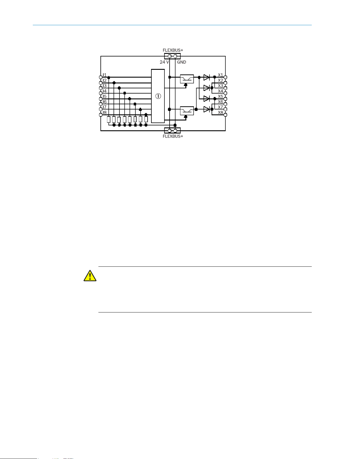
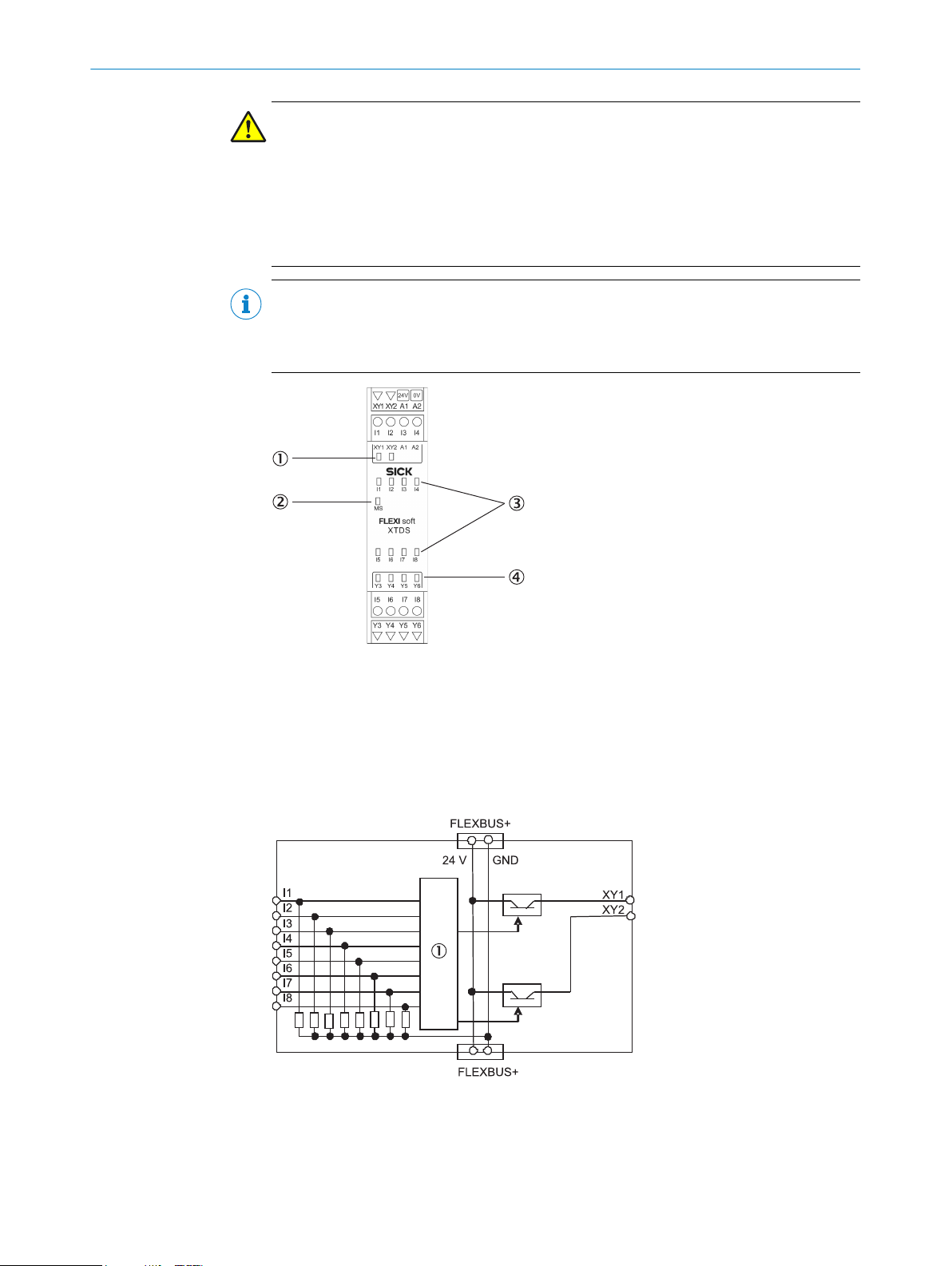
3.4.8 FX3-XTDS I/O module
Description
PRODUCT DESCRIPTION 3
T
he FX3-XTDS module is an input/output expansion module with 8 safe inputs and
4 non-safe outputs. It has 2 test pulse generators, one for test output XY1 and one for
test output XY2.
The FX3-XTDS module supports the following functions:
Monitoring of the connected safety devices (see "Connection of devices",
•
page 74)
Forwarding of information at inputs I1 to I8 to the main module
•
Receipt of control signals from the main module and corresponding switching of
•
outputs
Outputs XY1 and XY2 can be used as either test outputs or non-safe outputs.
•
WARNING
proper use of the non-safe outputs
Im
The dangerous state may not be stopped or not be stopped in a timely manner in the
event of non-compliance.
Do not use the FX3-XTDS outputs for safety functions.
b
The FX3-XTDS module cannot be operated alone; an FX3-CPUx main module is always
nece
ssary.
Multiple FX3-XTDS modules can be used at the same time (see "Construction and func‐
tion", page 16).
The power supply to the internal logic and the test outputs is provided via the system
plug and the FLEXBUS+ internal bus.
The power supply to outputs Y3 to Y6 on the FX3-XTDS must be provided directly via
A1/A2 at the corresponding module.
8012478/15UF/2019-10-31 | SICK OP E RA T IN G I N ST R UC T IO N S | Flexi Soft Modular Safety Controller
Subject to change without notice
29
Page 30
3 PRODUCT DESCRIPTION
WARNING
ffectiveness of the protective device due to unrecognized short-circuits between the
Ine
test pulse generators
The dangerous state may not be stopped or not be stopped in a timely manner in the
event of non-compliance.
b
NOTE
If bo
sible to connect a tested element to one of these inputs I1 to I8. However, this element
is marked red in the hardware configuration as a warning.
Configure the test outputs of the Flexi Soft expansion modules with test gaps
≤ 4 ms and a test period ≥ 200 ms.
th outputs XY1 and XY2 are used as non-safe outputs, then it is nevertheless pos‐
Figure 12: FX3-XTDS I/O module
1
2
3
4
3.4.8.1 Internal structure
Figure 13: Internal structure of the FX3-XTDS – safe inputs and test outputs
1
2 LEDs for test outputs or non-safe outputs
MS LED (Module St
8 input LEDs
4 output LEDs
Internal logic
atus)
30
O PE R AT I NG IN S TR U CT I ON S | Flexi Soft Modular Safety Controller 8012478/15UF/2019-10-31 | SICK
Subject to change without notice
Page 31

PRODUCT DESCRIPTION 3
Figure 14: Internal structure of the FX3-XTDS – non-safe outputs
Internal logic
1
3.4.9 FX0-STIO I/O module
Description
T
he FX0-STIO module is an expansion module with 6 non-safe inputs, 6 non-safe out‐
puts, and 2 connections that can be used as either non-safe inputs or non-safe out‐
puts.
The FX0-STIO module supports the following functions:
Forwarding of information at inputs I1 to I6 to the main module
•
Receipt of control signals from the main module and corresponding switching of
•
outputs
WARNING
Im
proper use of the non-safe modules
The dangerous state may not be stopped or not be stopped in a timely manner in the
event of non-compliance.
The target safety-related level may not be achieved in the event of non-compliance.
Do not use the FX0-STIO for safety-related functions.
b
The FX0-STIO module cannot be operated alone; an FX3-CPUx main module is always
nece
ssary.
Multiple FX0-STIO modules can be used at the same time (see "Construction and func‐
tion", page 16).
The power supply to the internal logic is provided via the system plug and the FLEXBUS
+ internal bus.
The power supply to outputs Y1 to Y6 as well as to connections IY7 and IY8 on the FX0STIO must be provided directly via A1/A2 at the corresponding module.
8012478/15UF/2019-10-31 | SICK OP E RA T IN G I N ST R UC T IO N S | Flexi Soft Modular Safety Controller
Subject to change without notice
31
Page 32

3 PRODUCT DESCRIPTION
Figure 15: FX0-STIO I/O module
1
2
3
4
5
6
2 output LEDs
MS LED (Module St
2 input LEDs
4 output LEDs
4 input LEDs
2 LEDs for configurable inputs or outputs
atus)
Use of connections IY7 and IY8 on the FX0-STIO
T
he IY7 and IY8 connections on a FX0-STIO module can be used either as non-safe
inputs or non-safe outputs.
3.4.9.1 Internal structure
Figure 16: Internal structure of the FX0-STIO – non-safe inputs
1
Internal logic
32
O PE R AT I NG IN S TR U CT I ON S | Flexi Soft Modular Safety Controller 8012478/15UF/2019-10-31 | SICK
Subject to change without notice
Page 33

PRODUCT DESCRIPTION 3
Figure 17: Internal structure of the FX0-STIO – non-safe outputs
Internal logic
1
3.4.10 Drive Monitor FX3-MOC0
Description
T
he Drive Monitor FX3-MOC is an expansion module for the safe movement monitoring
of drive systems. In this context, movement means the speed level, speed ramp and
standstill position. The module has an interface to connect two encoders (e.g. A/B
incremental encoders, linear encoders, motor feedback systems or linear distance
measurement systems).
The FX3-MOC0 supports the following functions:
Connection of two encoders for one or two axes
•
°
°
°
°
Standstill monitoring
•
Speed monitoring
•
Direction monitoring
•
Processing of information from the encoders and control signals from the main
•
module in the internal logic of the FX3-MOC0. A dedicated logic editor with a num‐
ber of function blocks is available for this purpose.
Forwarding of information from the internal logic to the main module
•
A/B incremental encoders HTL 24 V, HTL 12 V, TTL, max. 300 kHz
A/B incremental encoder RS-422, max. 1 MHz
4)
Sine-cosine encoder 1 VPP, max. 120 kHz
SSI encoder, RS-422, max. 1 MBaud
NOTE
he sine/cosine signals of a HIPERFACE® interface can also be connected to
T
the encoder connection of the FX3-MOC0. In this way, the HIPERFACE® interface can
be used like a sine/cosine encoder.
Other HIPERFACE® functions cannot be used.
4)
8012478/15UF/2019-10-31 | SICK OP E RA T IN G I N ST R UC T IO N S | Flexi Soft Modular Safety Controller
Subject to change without notice
y possible for encoder 1 (ENC1).
Onl
33
Page 34

3 PRODUCT DESCRIPTION
The FX3-MOC0 cannot be operated alone, but always requires an FX3-CPUx main mod‐
ule w
•
•
Up to 6 FX3-MOC0 modules can be used at the same time (see "Construction and func‐
tion", page 16). Each FX3-MOC0 connected reduces the possible number of other
expansion modules by two.
The power supply to the internal logic is provided via the system plug and the FLEXBUS
+ internal bus.
ith the following firmware version:
FX3-CPU0 and FX3-CPU1: ≥ V2.50.0
All other FX3-CPUx modules (FX3-CPU2, etc): all firmware versions
Figure 18: Drive Monitor FX3-MOC0
MS LED (Module St
1
atus)
WARNING
Ine
ffectiveness of the protective device due to selection of an unsuitable encoder
The target safety-related level may not be achieved in the event of non-compliance.
Select a suitable encoder.
b
Take suitable measures against the encoder’s systematic errors and common
b
causes of error.
Choosing the right encoder is crucial to achieving the desired safety integrity level (SIL) and performance level (PL).
ystematic faults and common cause faults (CCF), in particular, need to be minimized in this case.
S
Table 8: Achievable SIL and PL
Use of encoders Possible
a
xes per
FX3-MOC0
One sine-cosine safety encoder
.g., DFS60S Pro)
(e
2 SIL2, SILCL2, PL d
Achievable
SIL (IEC 61508),
SILCL (EN 62061) or
PL (EN ISO 13849-1)
Available functions for detecting encoder errors
1)
ine-cosine analog voltage monitoring
S
•
Monitoring of the ID code of the encoder/
•
motor feedback connection box in order to
detect a break in the FX3-MOC0 connection
3)
cable
2)
34
O PE R AT I NG IN S TR U CT I ON S | Flexi Soft Modular Safety Controller 8012478/15UF/2019-10-31 | SICK
Subject to change without notice
Page 35

PRODUCT DESCRIPTION 3
Use of encoders Possible
a
xes per
FX3-MOC0
Two encoders with relative position,
hosen from the following:
c
A/B
•
Sine-cosine
•
SSI
•
They can be the same type or differ‐
ent types
1)
Actual values: see
2)
Can be configured for sine-cosine encoders in the hardware configuration of the configuration software.
3)
Can be used by any type of encoder supported in the hardware configuration of the configuration software.
4)
Can be used in the FX3-MOC0 logic. For detailed information, see the “Flexi Soft in the Flexi Soft Designer Configuration Software” operat‐
ing instructions.
table 142, page 152.
1 SIL3, SILCL3, PL e
Achievable
SIL (IEC 61508),
SILCL (EN 62061) or
PL (EN ISO 13849-1)
Available functions for detecting encoder errors
1)
Speed c
•
Monitoring of the ID code of the encoder/
•
motor feedback connection box in order to
detect a break in the FX3-MOC0 connection
cable
omparison function block
3)
4)
Suitable measures against common causes of error
T
he following notes are identical for all FX3-MOCx modules.
In particular when both encoders are used for redundant monitoring of an axis, the fol‐
lowing possibilities must be taken into account, among others:
The common GND connection can be interrupted by the common connecting cable
•
on the FX3-MOCx for both encoders as a common reference potential for both
encoders.
The supply voltage for the encoder can be too low or completely interrupted.
•
The common supply voltage for both encoders can be too high. This may damage
•
both encoders. When using PELV/SELV voltage supplies without additional protec‐
tive measures, you must usually assume a voltage increase to 60 V here.
The entire encoder connection to the FX3-MOCx can be interrupted.
•
The following options are available to detect errors in the encoder system with the Flexi
Soft safety controller:
Use at least one encoder/motor feedback connection box. A description of this
•
function can be found in the “Flexi Soft in the Flexi Soft Designer Configuration
Software” and “Flexi Soft in the Safety Designer Configuration Software” operating
instructions in the “Encoder connection type and monitoring of ID identifier” sec‐
tion.
Use a sine/cosine encoder with activated sine/cosine analog voltage monitoring.
•
A description of this function can be found in the “Flexi Soft in the Flexi Soft
Designer Configuration Software” and “Flexi Soft in the Safety Designer Configura‐
tion Software” operating instructions in the “Sine-cosine analog voltage monitor‐
ing” section.
Use an SSI encoder with evaluation of error bits. A bit in the SSI data is needed
•
which takes on an inverted state if the watched error occurs, for example because
the supply voltage of the encoders is too low or because one or several of the
cables from the encoder to the FX3-MOCx are disconnected. A description of this
function can be found in the “Flexi Soft in the Flexi Soft Designer Configuration
Software” and “Flexi Soft in the Safety Designer Configuration Software” operating
instructions in the “SSI encoder” section.
5)
5)
C
onfigurable for sine/cosine encoders in the hardware configuration of the configuration software.
8012478/15UF/2019-10-31 | SICK OP E RA T IN G I N ST R UC T IO N S | Flexi Soft Modular Safety Controller
Subject to change without notice
35
Page 36

3 P
RODUCT DESCRIPTION
here is no possibility to detect faults immediately using the encoder signals when
T
•
using A/B incremental encoders.
Additionally, in certain cases there will be the option to check the plausibility of the
•
encoder’s motion signal using another signal from the process in conjunction with
the logic of the Drive Monitor and main module, e.g. with a signal "drive
running/not running".
There are the following options to control the voltage increase within the limits of a
PELV/SELV voltage supply, as long as the faults to be accepted are not controlled by
one of the selected monitoring functions:
Use separate voltage supplies for both encoders.
b
Use encoders that are equipped for the increased supply voltage to be accepted.
b
Either use the voltage supply of the FX3-MOCx module for the encoder (ENC1_24V
b
and/or ENC2_24V) directly or via the encoder/motor feedback connection box. If
the supply voltage for the Flexi Soft system exceeds 35 V at the system plug of the
main module, then the system switches into a safe state, i.e. the safe outputs are
switched off. In this way, safe switching off in the application in the event of a volt‐
age increase can be controlled. In this case, it is still possible for the encoder to be
damaged.
3.4.11 Drive Monitor FX3-MOC1
6)
Description
he Drive Monitor FX3-MOC1 is an expansion module for the safe movement monitor‐
T
ing of drive systems. In this context, movement means speed level, speed ramp and
position. The module has an interface to connect two encoders (e.g. A/B incremental
encoders, linear encoders, motor feedback systems or linear distance measurement
systems).
The FX3-MOC1 offers the following functions:
Connection of two encoders for one or two axes
•
A/B incremental encoders HTL 24 V, HTL 12 V, TTL, max. 300 kHz
°
A/B incremental encoder RS-422, max. 1 MHz
°
Sine-cosine encoder 1 VPP, max. 120 kHz
°
SSI encoder, RS-422, max. 1 MBaud
°
Position monitoring
•
Standstill monitoring
•
Speed monitoring
•
Speed cross check
•
Direction monitoring
•
Processing of information from the encoders and control signals from the main
•
7)
module in the internal logic of the FX3-MOC1. A dedicated logic editor with a num‐
ber of function blocks is available for this purpose.
Forwarding of information from the internal logic to the main module
•
NOTE
T
he sine/cosine signals of a HIPERFACE® interface can also be connected to
the encoder connection of the FX3-MOC1. In this way, the HIPERFACE® interface can
be used like a sine/cosine encoder.
Other HIPERFACE® functions cannot be used.
The FX3-MOC1 cannot be operated alone, but always requires an FX3-CPUx main mod‐
ith the following firmware version:
ule w
6)
T
his also applies for A/B incremental encoders with 2 output pairs. Fault detection based on the inverted output signals would allow for
cable monitoring, although it would not be possible to detect all faults to be accepted in an A/B incremental encoder such as a static
state of the output level.
7)
Only possible for encoder 1 (ENC1).
36
O PE R AT I NG IN S TR U CT I ON S | Flexi Soft Modular Safety Controller 8012478/15UF/2019-10-31 | SICK
Subject to change without notice
Page 37

PRODUCT DESCRIPTION 3
CPU0 and FX3-CPU1: ≥ V2.50.0
FX3-
•
All other FX3-CPUx modules (FX3-CPU2, etc.): all firmware versions
•
Up to 6 FX3-MOC1 modules can be used at the same time (see "Construction and func‐
tion", page 16). Each FX3-MOC1 connected reduces the possible number of other
expansion modules by two.
The internal logic is supplied with voltage via the system plug and the internal FLEXBUS
+ bus.
Figure 19: Drive Monitor FX3-MOC1
MS LED (module st
1
atus)
WARNING
Ine
ffectiveness of the protective device due to selection of an unsuitable encoder
The target safety-related level may not be achieved in the event of non-compliance.
Select a suitable encoder.
b
Take suitable measures against the encoder’s systematic errors and common
b
causes of error.
Choosing the right encoder is crucial to achieving the desired safety integrity level (SIL) and performance level (PL).
ystematic faults and common cause faults (CCF), in particular, need to be minimized in this case.
S
Table 9: Achievable SIL and PL
Use of encoders Possible
a
xes per
FX3-MOC1
A sine/cosine safety encoder (e.g.
DFS60S Pr
One sine-cosine safety encoder
(e
.g., DFS60S Pro) with
•
•
•
o)
Safe Plc cam (i.e., with corre‐
sponding SIL, SILCL, or PL)
Position by Reference function
block
Reference run after restart
2 SIL2, SILCL2, PL d for
2 SIL2, SILCL2, PL d for
Achievable
SIL (IEC 61508),
SILCL (EN 62061) or
PL (EN ISO 13849-1)
speed monitoring (incl.
direction and standstill
monitoring)
position monitoring
(incl. speed, direction,
and standstill monitor‐
ing)
Available functions for detecting encoder errors
1)
ine-cosine analog voltage monitoring
S
•
Monitoring of the ID code of the encoder con‐
•
nection box in order to detect a break in the
FX3-MOC1 connection cable 3) (possible but
not necessary, as sine-cosine analog voltage
monitoring can detect a break in the connec‐
tion cable)
2)
8012478/15UF/2019-10-31 | SICK OP E RA T IN G I N ST R UC T IO N S | Flexi Soft Modular Safety Controller
Subject to change without notice
37
Page 38

3 P
RODUCT DESCRIPTION
Use of encoders Possible
a
xes per
FX3-MOC1
Two encoders with relative position,
hosen from the following:
c
A/B
•
Sine-cosine
•
SSI
•
They can be the same type or differ‐
ent types
A safety encoder with absolute posi‐
t
ion with
SSI + sine-cosine
•
with
Initial referencing during com‐
•
missioning
Position by Reference with
•
Restore function block
Two encoders with absolute posi‐
t
ion, chosen from the following:
A/B
•
Sine-cosine
•
SSI
•
A/B and sine-cosine must each be
supplemented as follows:
a)
Plc cam (not safe)
•
Position by Reference without
•
Restore function block
Reference run after restart
•
Or
b) (possible for a maximum of one
encoder)
Initial referencing during com‐
•
missioning
Position by Reference with
•
Restore function block
1)
Actual values: see
2)
Can be configured for sine-cosine encoders in the hardware configuration of the configuration software.
3)
Can be used by any type of encoder supported in the hardware configuration of the configuration software.
4)
Can be used in the FX3-MOC1 logics. For details, see the “Flexi Soft in the Flexi Soft Designer Configuration Software” and “Flexi Soft in the
Safety Designer Configuration Software” operating instructions.
table 145, page 158.
1 SIL3, SILCL3, PL e for
1 SIL3, SILCL3, PL e for
1
Achievable
SIL (IEC 61508),
SILCL (EN 62061) or
PL (EN ISO 13849-1)
speed monitoring (incl.
direction and standstill
monitoring)
position monitoring
(incl. speed, direction,
and standstill monitor‐
ing)
Available functions for detecting encoder errors
1)
Speed c
•
Function block position comparison
•
Monitoring of the ID code of the encoder/
•
motor feedback connection box in order to
detect a break in the FX3-MOC1 connection
cable
F
•
Monitoring of the ID identifier of the encoder/
•
motor feedback connection box for detecting
a tear in the FX3-MOC1 connecting cable
omparison function block
3)
unction block position comparison
4)
4)
4)
3)
38
Suitable measures against common causes of error
T
he following notes are identical for all FX3-MOCx modules.
In particular when both encoders are used for redundant monitoring of an axis, the fol‐
lowing possibilities must be taken into account, among others:
The common GND connection can be interrupted by the common connecting cable
•
on the FX3-MOCx for both encoders as a common reference potential for both
encoders.
The supply voltage for the encoder can be too low or completely interrupted.
•
O PE R AT I NG IN S TR U CT I ON S | Flexi Soft Modular Safety Controller 8012478/15UF/2019-10-31 | SICK
Subject to change without notice
Page 39

PRODUCT DESCRIPTION 3
he common supply voltage for both encoders can be too high. This may damage
T
•
both encoders. When using PELV/SELV voltage supplies without additional protec‐
tive measures, you must usually assume a voltage increase to 60 V here.
The entire encoder connection to the FX3-MOCx can be interrupted.
•
The following options are available to detect errors in the encoder system with the Flexi
Soft safety controller:
Use at least one encoder/motor feedback connection box. A description of this
•
function can be found in the “Flexi Soft in the Flexi Soft Designer Configuration
Software” and “Flexi Soft in the Safety Designer Configuration Software” operating
instructions in the “Encoder connection type and monitoring of ID identifier” sec‐
tion.
Use a sine/cosine encoder with activated sine/cosine analog voltage monitoring.
•
A description of this function can be found in the “Flexi Soft in the Flexi Soft
Designer Configuration Software” and “Flexi Soft in the Safety Designer Configura‐
tion Software” operating instructions in the “Sine-cosine analog voltage monitor‐
ing” section.
Use an SSI encoder with evaluation of error bits. A bit in the SSI data is needed
•
which takes on an inverted state if the watched error occurs, for example because
the supply voltage of the encoders is too low or because one or several of the
cables from the encoder to the FX3-MOCx are disconnected. A description of this
function can be found in the “Flexi Soft in the Flexi Soft Designer Configuration
Software” and “Flexi Soft in the Safety Designer Configuration Software” operating
instructions in the “SSI encoder” section.
There is no possibility to detect faults immediately using the encoder signals when
•
using A/B incremental encoders.
Additionally, in certain cases there will be the option to check the plausibility of the
•
encoder’s motion signal using another signal from the process in conjunction with
the logic of the Drive Monitor and main module, e.g. with a signal "drive
running/not running".
9)
8)
There are the following options to control the voltage increase within the limits of a
PELV/SELV voltage supply, as long as the faults to be accepted are not controlled by
one of the selected monitoring functions:
Use separate voltage supplies for both encoders.
b
Use encoders that are equipped for the increased supply voltage to be accepted.
b
Either use the voltage supply of the FX3-MOCx module for the encoder (ENC1_24V
b
and/or ENC2_24V) directly or via the encoder/motor feedback connection box. If
the supply voltage for the Flexi Soft system exceeds 35 V at the system plug of the
main module, then the system switches into a safe state, i.e. the safe outputs are
switched off. In this way, safe switching off in the application in the event of a volt‐
age increase can be controlled. In this case, it is still possible for the encoder to be
damaged.
3.4.12 FX3-ANA0 analog input module
Function
he FX3-ANA0 analog input module has two analog inputs for connecting analog signal
T
transmitters (sensors). Both inputs form an input pair and are used to detect an analog
process variable. As part of a safety function, the FX3-ANA0 monitors whether the cur‐
rent value of this process variable (measured value) is within the permitted process
range. It can also assign the measured value to one of up to 15 configurable signal
ranges.
8)
C
onfigurable for sine/cosine encoders in the hardware configuration of the configuration software.
9)
This also applies for A/B incremental encoders with 2 output pairs. Fault detection based on the inverted output signals would allow for
cable monitoring, although it would not be possible to detect all faults to be accepted in an A/B incremental encoder such as a static
state of the output level.
8012478/15UF/2019-10-31 | SICK OP E RA T IN G I N ST R UC T IO N S | Flexi Soft Modular Safety Controller
Subject to change without notice
39
Page 40

1
2
3
3 PRODUCT DESCRIPTION
NOTE
In some applic
monitored. It is not possible for the FX3-ANA0 to perform an explicit calculation of the
ratio between different values.
The FX3-ANA0 analog input module offers the following functions:
•
•
•
•
•
•
The FX3-ANA0 analog input module cannot be operated alone; an FX3-CPUx main mod‐
ule is always required.
ations, adherence to the ratio of the detected sensor values must be
P
lausibility check of the analog values detected at inputs AI1 and AI2
Configurable evaluation of the detected analog values in the module
Monitoring of up to 15 different process areas. A process area consists of an
upper and a lower process area limit. If the measured process size of one of these
limits is exceeded or undercut, the Release bit is set to 0. The process area to be
monitored can be selected in ongoing operation.
Subdivision of the maximum monitoring range into up to 15 configurable signal
ranges
Output of bits for Enable and the number of the current signal range to the main
module for evaluation in the logic editor
Output of sensor values via a gateway (16-bit, non-synchronous output, non-safe
transmission)
Multiple FX3-ANA0 can be used at the same time (see "Construction and function",
page 16).
The FX3-ANA0 is supplied with voltage via the main module system plug and the inter‐
nal FLEXBUS+ bus.
Figure 20: FX3-ANA0 analog input module
MS LED (module status)
1
LED AI1
2
LED AI2
3
40
Configuration
T
he FX3-ANA0 is configured using the Flexi Soft Designer or Safety Designer configura‐
tion software.
NOTE
evices with firmware < V2.00.0 are not supported by the Safety Designer configura‐
D
tion software.
O PE R AT I NG IN S TR U CT I ON S | Flexi Soft Modular Safety Controller 8012478/15UF/2019-10-31 | SICK
Subject to change without notice
Page 41

PRODUCT DESCRIPTION 3
For detailed information on configuring the FX3-ANA0, see the “Flexi Soft in the
F
lexi Soft Designer Configuration Software” and “Flexi Soft in the Safety Designer Con‐
figuration Software” operating instructions.
Sensors
WARNING
ffectiveness of the protective device due to selection of unsuitable sensors
Ine
The target safety-related level may not be achieved in the event of non-compliance.
Select suitable sensors.
b
Take suitable measures against the sensors’ systematic errors and common
b
causes of error.
Choosing the right sensors is crucial to achieving the desired safety integrity level (SIL)
and per
ticular, need to be minimized in this case.
Sensors featuring diverse redundancy are supported for the safe measurement of a
process variable. The characteristic lines of the sensors are standardized in the module
for this purpose. The standardized measured values of the two sensors are compared
with one another in order to check their plausibility.
formance level (PL). Systematic faults and common cause faults (CCF), in par‐
Uniformly redundant sensors can also be used. In this case, the characteristic lines of
both sensors must have identical configurations.
Depending on the process variable, a time delay can occur at sensors which are
attached at a distance from one another within a local area, or which have different
transceivers. This transit time difference can be taken into account during the plausibil‐
ity check.
Instead of two redundant sensors, an individual single-channel or dual-channel safety
sensor can be used. A single-channel safety sensor must be connected in series to
both inputs.
For information on connecting the sensors, see "C
page 94.
For detailed information on configuring the connected sensors, see the “Flexi Soft in
the Flexi Soft Designer Configuration Software” and “Flexi Soft in the Safety Designer
Configuration Software” operating instructions.
3.4.13 UE410-2RO/UE410-4RO relay modules
Description
T
he UE410-2RO/UE410-4RO relay modules provide dual-channel, contact-based out‐
puts with what are known as positively guided relay contacts.
onnecting analog sensors",
8012478/15UF/2019-10-31 | SICK OP E RA T IN G I N ST R UC T IO N S | Flexi Soft Modular Safety Controller
Subject to change without notice
41
Page 42

3 P
RODUCT DESCRIPTION
1
2
NOTE
T
he relay modules do not communicate via the internal FLEXBUS+ bus. They are there‐
fore incapable of receiving any control signals from the main module.
A maximum of 4 UE410-4RO relay modules or 8 UE410-2RO relay modules can be con‐
nec
be available.
Other modules from the Flexi Classic product family cannot be integrated into the Flexi
Soft system.
3.4.13.1 Internal structure
UE410-2RO
T
he UE410-2RO relay module has a control input (B1). This controls two internal relays
and provides a redundant cut-off path, consisting of:
•
•
•
Figure 21: UE410-2RO relay module
PWR LED (power)
K1/2 LED
Figure 22: UE410-4RO relay module
PWR LED (power)
1
K1/2 LED
2
K3/4 LED
3
ted to a Flexi Soft system; in other words, a maximum of 16 safe relay outputs may
Two safe enabling current paths (13/14, 23/24), dual-channel and volt-free
One signaling current path (Y14), dual-channel and connected internally to 24 V
DC
One feedback circuit external device monitoring (Y1/Y2), dual-channel and voltfree
42
Figure 23: Internal structure of the UE410-2RO
O PE R AT I NG IN S TR U CT I ON S | Flexi Soft Modular Safety Controller 8012478/15UF/2019-10-31 | SICK
Subject to change without notice
Page 43

PRODUCT DESCRIPTION 3
UE410-4RO
T
he UE410-4RO relay module has two control inputs (B1, B2). These each control two
internal relays. Two independent, redundant cut-off paths are therefore available.
Control input (B1) actuates two internal relays and provides a redundant cut-off path
consisting of:
Two safe enabling current paths (13/14, 23/24), dual-channel and volt-free
•
One signaling current path (Y14), dual-channel and connected internally to 24 V
•
DC
One feedback circuit external device monitoring (Y1/Y2), dual-channel and volt-
•
free
Control input (B2) actuates two internal relays and provides a redundant cut-off path
consisting of:
Two safe enabling current paths (33/34, 43/44), dual-channel and volt-free
•
One signaling current path (Y24), dual-channel and connected internally to 24 V
•
DC
One feedback circuit external device monitoring (Y3/Y4), dual-channel and volt-
•
free
This means that the UE410-4RO relay module has twice the number of functions as the
UE410-2RO.
3.5 Interfaces
3.5.1 RS-232
Figure 24: Internal structure of the UE410-4RO
Each main module has an RS-232 interface with the following functions:
ransfer configuration from the configuration software to the system plug
T
•
Import configuration from the system plug into the configuration software
•
Diagnose the Flexi Soft system with the configuration software
•
Continuous diagnostics of the Flexi Soft system via a connected PLC As such the
•
RS-232 interface can provide an alternative to a gateway.
Table 10: Pin assignment of the RS-232 interface on the FX3-CPUx
Male connector/
emale connector
F
Pin Signal Color Computer-side pin
assignmentRS-232
D-Sub (9-pin)
1 Reserved Brown –
2 RxD White Pin 3
3 GND (connected electrically
ernally to connection A2
int
on the main module)
4 TxD Black Pin 2
Blue Pin 5
8012478/15UF/2019-10-31 | SICK OP E RA T IN G I N ST R UC T IO N S | Flexi Soft Modular Safety Controller
Subject to change without notice
43
Page 44

3 P
RODUCT DESCRIPTION
NOTICE
ound loops
Gr
The device may be damaged if this is not observed.
Avoid ground loops between the GND connection of the RS-232 interface and the
b
A2 connection of the main module, for instance by using optocouplers.
If the RS-232 interface of the main module is permanently connected (e.g. as an
b
alternative to a gateway), then observe the maximum permitted length of cable of
3 m.
3.5.2 USB
The FX3-CPU3 main module has a USB interface with the following functions:
ransfer configuration from the configuration software to the system plug
T
•
Import configuration from the system plug into the configuration software
•
Diagnose the Flexi Soft system with the configuration software
•
3.5.3 Enhanced Function Interface (EFI)
The FX3-CPU1, FX3-CPU2, and FX3-CPU3 main modules each have 2 EFI interfaces.
T
he properties, the functions, and the benefits of these interfaces are described in this
section.
The general EFI description of operation and the combination options of SICK products
regarding EFI can be found in the “EFI - enhanced function interface” technical informa‐
tion (SICK part number 8012611).
Definition
An E
FI interface is safe communication interface between SICK devices. Information
can be read from EFI-enabled devices and commands can be sent to EFI-enabled
devices.
Properties
Each EFI interface can support up to 4 SICK devices, as long as the EFI-enabled
•
devices support this number.
Device connection via 2-wire cable
•
Various possible device combinations
•
Sensor with sensor in same product family
°
Sensor with safety controllers and gateways
°
Connection of up to four FX3-CPU1, FX3-CPU2, or FX3-CPU3 main modules to
°
one Flexi Link system (see "Flexi Link", page 45)
Transfer of status information (process data) between SICK devices with EFI inter‐
•
face
Transfer of configuration from the configuration software to EFI-enabled devices
•
Import of configuration from EFI-enabled devices into the configuration software
•
Activation/use of advanced software functions
•
44
Functions
Alongside the product-specific functions of each of the EFI-enabled devices, the follow‐
ing functions are available:
General functions
Status information (process data) from the EFI-enabled devices is available in the
•
controller and at the sensor.
Diagnostic information from all EFI-enabled devices is available in the controller.
•
Transfer of configuration information
•
O PE R AT I NG IN S TR U CT I ON S | Flexi Soft Modular Safety Controller 8012478/15UF/2019-10-31 | SICK
Subject to change without notice
Page 45

Special functions
S
•
Protective field switching
•
Function switching
•
Operating mode selection
•
Signal routing
•
Remote diagnostic information via Ethernet
•
Information about the location of an interruption in a protective field in the case of
•
host-guest applications.
Expansion of signals and forwarding of results
•
Benefits
Installation is quicker and less expensive (only 2 conductors) when signals from
•
multiple sensors are used
Decrease the material costs with the savings potential of function blocks, inputs
•
and outputs
Higher availability thanks to the provision of diagnostic information with high infor‐
•
mation content for quick and accurate possible actions
3.6 Special functions
PRODUCT DESCRIPTION 3
imultaneous protective field evaluation
3.6.1 Flexi Link
Overview
F
lexi Link allows you to combine up to four Flexi Soft stations via EFI for safe data
exchange. Only main modules FX3-CPU1 and higher can be used in a Flexi Link system.
FX3-CPU0 main modules cannot be connected.
The process data of each station (inputs and outputs, logic results, etc.) can be made
available to all other stations in the Flexi Link system. The teach function can be used
to deactivate individual stations temporarily without impairing the operation of the over‐
all system.
Features
S
afe connection of up to four Flexi Soft stations via EFI
•
Connection via EFI1 or EFI1+2
•
Transmission/receipt of up to 52 bits of information per station (26 bits per EFI
•
interface)
A tag name that is valid globally can be assigned to each bit.
•
Teaching simulates the presence of stations that have been temporarily sus‐
•
pended (switched off).
Any station can be used for access in order to address and configure the entire
•
system with the configuration software.
The configuration of the entire Flexi Link system is saved in a unique project file.
•
System requirements and restrictions
The following minimum system requirements must be met for Flexi Link:
Table 11: System requirements for Flexi Link
System component Version
Hardware FX3-CPU1, FX3-CPU2, or FX3-CPU3 with firmware version ≥ V2.00.0
Software Flexi Soft Designer version ≥ V1.3.0
The Flexi Link system can either by connected via EFI1 only or via EFI1+2. The number
of piece
same Flexi Link system depends on which connection type is used.
8012478/15UF/2019-10-31 | SICK OP E RA T IN G I N ST R UC T IO N S | Flexi Soft Modular Safety Controller
Subject to change without notice
s of data per station that can be made available to the other stations in the
45
Page 46

3 PRODUCT DESCRIPTION
Table 12: Available data depending on connection type
Type of connection Data availability per station
EFI1 26 bits
EFI1+2 52 bits
NOTE
•
•
•
3.6.2 Flexi Line
Overview
lexi Line allows you to network up to 32 Flexi Soft stations safely. Only main modules
F
FX3-CPU3 and higher can be used in a Flexi Line system. It is not possible to connect
any of the other main modules (FX3-CPU0, FX3-CPU1, FX3-CPU2).
ou cannot use Flexi Link and EFI communication at the same time, i.e., it is not
Y
possible to connect other EFI-enabled devices to EFI2 if you are using EFI1 for
Flexi Link.
The process data sent from any station is received by all other stations at virtually
the same time. However, the data is not necessarily processed (logic) at the same
time, because the stations are not synchronized.
The data is consistent within EFI1 and consistent within EFI2. However, the data
from EFI1 and the data from EFI2 may be inconsistent for a short period of time
because it is transmitted separately.
A single process image is defined for the entire Flexi Line system. Each byte in this
process image is valid either globally, i.e., in the entire system, or locally, i.e., only for
the corresponding station and its neighbor stations. Each Flexi Line station uses this
process image to communicate with its neighbor stations. Thanks to the topology,
addresses are not required in order for communication to take place.
Features
S
afe connection of up to 32 Flexi Soft stations via the Flexi Line interface
•
Topology without addresses: If the sequence of the stations changes, simply con‐
•
firm the new arrangement by performing a teach-in operation.
The EFI interface remains available without restrictions:
•
EFI-enabled devices can be connected.
°
A Flexi Link system can be connected.
°
A global process image is defined for all stations.
•
Bytes that are valid globally or locally can be defined in the process image.
•
The process image can contain up to 12 bytes or 96 bits.
•
The maximum cable length between 2 stations is 1,000 meters. The possible total
•
length of a system with 32 stations is, therefore, 31 kilometers.
System requirements and restrictions
T
he following minimum system requirements must be met for Flexi Line:
Table 13: System requirements for Flexi Line
System component Version
Hardware FX3-CPU3, every firmware version
Software Flexi Soft Designer version ≥ V1.6.0
46
O PE R AT I NG IN S TR U CT I ON S | Flexi Soft Modular Safety Controller 8012478/15UF/2019-10-31 | SICK
Subject to change without notice
Page 47

3.6.3 Muting
PRODUCT DESCRIPTION 3
NOTE
ou can even use Flexi Link or EFI communication simultaneously with Flexi Line,
Y
•
i.e., it is possible to connect either EFI-enabled devices or Flexi Link stations.
The process image is transferred from station to station at a fixed update rate.
•
However, the data is not necessarily processed (logic) at the same time, because
the stations are not synchronized.
The update rate of the Flexi Line system is determined by the maximum cable
•
length between two stations and the size of the process image.
Table 14: Update rate of a Flexi Line system dependent on the maximum cable length and the
si
ze of the process image
Max. cable length 32 bits 64 bits 96 bits
125 m 2 ms 2 ms 4 ms
250 m 2 ms 4 ms 8 ms
500 m 4 ms 8 ms 12 ms
1,000 m 8 ms 12 ms 20 ms
General description
ing automatically and temporarily overrides the safety-related functions provided by
Mut
a control system or a safety device. Muting is used to move specific objects (pallets
loaded with goods, for example) through an electro-sensitive protective device such as
a safety light curtain and into a hazardous area. During this transport operation, the
muting function overrides monitoring by the electro-sensitive protective device.
For the further approach, observe the notes in the “Flexi Soft in the Flexi Soft Designer
Configuration Software” and “Flexi Soft in the Safety Designer Configuration Software”
operating instructions.
SICK muting sensors
A se
lection of optical muting sensors are presented below. You can use these sensors
by type (light or dark switching).
Table 15: Selection and settings of optical SICK muting sensors in muting applications
Model Function
W9-3 Light/dark switching, complementary
W12-3
W18-3
W27-3
W24-3 Light/dark switching, switchable
NOTE
he following criteria apply when selecting and setting optical SICK muting sensors in
T
muting applications:
Outputs must be PNP-switching.
•
Note the output level in the table below.
•
Table 16: Output level of muting sensors
Output level of muting sensors State
High Activated, material detected
Low Deactivated, no material detected
8012478/15UF/2019-10-31 | SICK OP E RA T IN G I N ST R UC T IO N S | Flexi Soft Modular Safety Controller
Subject to change without notice
47
Page 48

RODUCT DESCRIPTION
3 P
3.6.4 Automatic configuration recovery (ACR)
When an FX3-MPL1 system plug is used, EFI-enabled devices of the same type can be
de
tected and automatically reconfigured further to a replacement (automatic configura‐
tion recovery). Advantages:
Configuration backup of EFI sensors in FX3-CPU2 and FX3-CPU3
•
Rapid device replacement without reconfiguration with the corresponding configu‐
•
ration software
Quick and easy duplication of equipment in series machine manufacture
•
ACR can be used to restore the configuration of the following device families:
S3000 with firmware version ≥ B02.41, not in Compatibility mode. For details,
•
refer to the “Compatibility mode” chapter of the S3000 operating instructions
(SICK part number 8009791).
S300 with firmware version ≥ 02.10, not in Compatibility mode. For details, refer
•
to the “Compatibility mode” chapter of the S300 operating instructions (SICK part
number 8010946).
S300 Mini
•
M4000
•
C4000
•
ACR cannot be used to restore the configuration of the following devices:
UE product family (UE402/UE403, UE44xx, UE41xx, UExx40)
•
Devices in the Flexi Soft product family (FX3-CPUx)
•
Please also refer to the information in the operating instructions for the EFI-enabled
devices you are using.
The “Flexi Soft in the Flexi Soft Designer Configuration Software” operating instructions
contain more information on using the ACR function.
48
O PE R AT I NG IN S TR U CT I ON S | Flexi Soft Modular Safety Controller 8012478/15UF/2019-10-31 | SICK
Subject to change without notice
Page 49

4 Mounting
MOUNTING 4
WARNING
Ine
ffectiveness of the protective device due to unsuitable mounting location
The target safety-related level may not be achieved in the event of non-compliance.
Mount the Flexi Soft system in an environment corresponding to enclosure rating
b
IP54 (EN 60529), e.g. inside a control cabinet with enclosure rating IP54.
NOTICE
Im
proper mounting
The device may be damaged if this is not observed.
Switch off the supply voltage before adding or removing modules.
b
Ensure suitable ESD protective measures during mounting.
b
Assignment of the modules:
ithin a Flexi Soft system, the FX3-CPUx main module is always located on the far
W
•
left.
Up to two gateways can be used per system. The two optional gateways must be
•
mounted directly to the right of the main module of the Flexi Soft system.
All other Flexi Soft expansion modules (e.g. the FX3-XTIO, FX3-XTDI, or FX3-MOCx)
•
must be mounted to the right of the gateways. The expansion modules can be
mounted in any order.
Any additional relay modules (the UE410-2RO or UE410-4RO) must be mounted to
•
the right of the expansion modules.
Mounting the modules:
The modules are housed in a 22.5 mm wide housing for standard 35 mm rails in
•
accordance with EN 60715 (DIN mounting rail).
The modules are interconnected via a FLEXBUS+ plug connector, which is inte‐
•
grated into the housing. The Flexi Soft modules must be pushed approximately
10 mm apart before a module can be removed from the DIN mounting rail.
The modules must be installed in the control cabinet so that the minimum dis‐
•
tance of the Flexi Soft modules to the control cabinet is upheld. This distance is
50 mm above and below the modules and 25 mm to the front and back.
The Flexi Soft system must be installed vertically so that optimal air circulation is
•
possible.
Modules with ventilation slots (e.g., the EtherCAT gateway) must be mounted so
•
that the air can circulate vertically. The ventilation slots must be positioned at the
top and bottom.
Mount the modules in accordance with EN 50274.
b
Make sure that the voltage supply for the Flexi Soft system is switched off.
b
Implement suitable measures to prevent any foreign bodies from entering the con‐
b
nector openings, particularly those of the system plug.
8012478/15UF/2019-10-31 | SICK OP E RA T IN G I N ST R UC T IO N S | Flexi Soft Modular Safety Controller
Subject to change without notice
49
Page 50

1
3
2
4 MOUNTING
Figure 25: Mounting the module on the DIN mounting rail
b Hook t
he device onto the DIN mounting rail (1).
b The grounding clip (2) must sit flush against the DIN mounting rail so that it is
secure and can conduct electricity effectively.
Snap the module into place on the DIN mounting rail by applying slight pressure in
b
the direction of the arrow (3).
Figure 26: Attaching the end pieces
S
lide the modules together one by one (as indicated by the arrows) until the side-
b
mounted plug connector engages.
Mount the end pieces on the left- and right-hand sides.
b
50
The following steps are necessary after mounting and installation:
Establish the electrical connections (see "Electrical installation", page 51)
•
Configuration (“Flexi Soft in the Flexi Soft Designer Configuration Software” and
•
“Flexi Soft in the Safety Designer Configuration Software” operating instructions)
Check the installation (see "Checks before initial commissioning", page 102)
•
NOTE
To mount and remove the encoder/motor feedback connection boxes, see the mount‐
ing instructions for the encoder/motor feedback connection boxes at www.sick.com.
O PE R AT I NG IN S TR U CT I ON S | Flexi Soft Modular Safety Controller 8012478/15UF/2019-10-31 | SICK
Subject to change without notice
Page 51

5 Electrical installation
NOTE
T
his chapter deals with the electrical installation of the Flexi Soft system inside the con‐
trol cabinet. You will find additional information about the electrical connection of other
devices to the Flexi Soft system in the section about the corresponding device: (see
"Connection of devices", page 74).
5.1 Requirements to be met by the electrical installation
WARNING
E
lectrical voltage
There is a risk of injury from electrocution while connecting the devices.
Disconnect the power for the entire plant/machine.
b
WARNING
Unintended start of the plant/machine
The plant/machine could inadvertently start while you are connecting the devices.
ELECTRICAL INSTALLATION 5
Disconnect the power for the entire plant/machine.
b
WARNING
ffectiveness of the protective device due to non-compliance with safety standards
Ine
The target safety-related level may not be achieved in the event of non-compliance.
Observe the relevant safety standards (e.g. EN 62061, or EN ISO 13849-1) for all
b
the safety-related parts of the plant (wiring, connected sensors and control
devices, configuration, external device monitoring).
8012478/15UF/2019-10-31 | SICK OP E RA T IN G I N ST R UC T IO N S | Flexi Soft Modular Safety Controller
Subject to change without notice
51
Page 52

5 ELE
CTRICAL INSTALLATION
NOTE
or the electrical installation, observe the following:
F
The Flexi Soft safety controller meets the EMC requirements stipulated by generic
•
standard EN 61000-6-2 for the industrial sector.
Industrial safety devices by SICK are only suitable for local direct current applica‐
•
tions. If the device is being used on power supply networks, e.g., in accordance
with IEC 61326-3-1, additional protective measures must be taken.
Machines on which safety devices are being used must be installed and dimen‐
•
sioned as appropriate for the lightning zone in accordance with EN 62305-1. The
required level can be achieved by using external protective devices. The devices
used to provide protection against overvoltage must meet the requirements set
out in EN 61643-11.
The equipment must prevent common-mode disturbance as set out in
•
IEC 61000-4-16 in the frequency range from 0 Hz to 150 kHz.
To establish full EMC safety, you must connect the DIN mounting rail to functional
•
earth (FE).
The external voltage supply of the Flexi Soft modules must be capable of buffering
•
brief power failures of 20 ms as specified in EN 60204-1, for example.
The power supply and all connected signals must meet the requirements for low
•
voltages with safe isolation (SELV, PELV) as set out in EN 60664 and EN 50178
(electronic equipment for use in power installations).
If the RS-232 interface on the main module is used as an alternative to a gateway,
•
then the maximum permitted length of cable is 3 m.
The GND of the RS-232 interface is connected internally to the GND connection of
•
the main module’s voltage supply (A2). Avoid ground loops between the GND con‐
nection of the RS-232 interface and the A2 connection of the main module, for
instance by using optocouplers.
Depending on the external loads and in particular in the case of inductive loads,
•
additional external safety measures such as varistors or RC elements may be nec‐
essary in order to protect the outputs. For information on limitations in operation:
see "Technical data", page 126. It must be considered that the response times
may be extended depending on the type of suppressor.
When modules are exchanged, the correct assignment of the terminals must be
•
ensured, e.g. by labelling or routing the cables correspondingly.
52
Electrical installation
C
arry out the electrical installation work in conformity with EN 60204-1.
b
Connect the shielding of all fieldbus and Ethernet cables to the functional earth
b
(FE) directly at the control cabinet entry point.
Connect the GND connections of the actuators to the outputs Q1 to Q4 in star for‐
b
mation with the GND connection of the voltage supply. Otherwise, an actuator (e.g.
relay) could switch unintentionally if the common GND cable tears off, at least one
output is high and at least one output for the actuators is low.
Make sure that all the Flexi Soft system modules, the connected protective
b
devices (e.g., the EFI-enabled devices), and the voltage supplies are all connected
to the same ground. The ground of the RS-232 interface is connected internally to
the ground of the main module’s voltage supply (A2).
O PE R AT I NG IN S TR U CT I ON S | Flexi Soft Modular Safety Controller 8012478/15UF/2019-10-31 | SICK
Subject to change without notice
Page 53

WARNING
nintended high status at the inputs due to reverse current in case of loss of ground
U
connection
The target safety-related level may not be achieved in the event of non-compliance.
The dangerous state may not be stopped or not be stopped in a timely manner in the
event of non-compliance.
If several safe inputs are switched in parallel:
Check whether this reverse current might lead to an unintentional high state, see
b
"Data sheet", page 135.
Consider this possible error source in the risk analysis and risk avoidance strategy.
b
5.2 Description of the terminals
5.2.1 FX3-CPU0 main module
ELECTRICAL INSTALLATION 5
Figure 27: FX3-CPU0 main module
FX3-MPL0 system plug
1
RS-232 interface
2
MS LED (Module Status)
3
CV LED (Configuration Verified)
4
Table 17: Pin assignment on the FX3-CPU0 main module with FX3-MLP0 system plug
Terminal Pin assignment
A1 24 V power supply for all modules, with the exception of the supply to
t
he outputs (Q1 … Q4)
A2 Power supply GND
8012478/15UF/2019-10-31 | SICK OP E RA T IN G I N ST R UC T IO N S | Flexi Soft Modular Safety Controller
Subject to change without notice
53
Page 54

5 ELECTRICAL INSTALLATION
5.2.2 FX3-CPU1 and FX3-CPU2 main modules
Figure 28: FX3-CPU1 main module
FX3-MPL0 system plug
1
RS-232 interface
2
EFI1_A
3
EFI1_B
4
MS LED (Module Status)
5
CV LED (Configuration Verified)
6
EFI1 LED
7
EFI2 LED
8
EFI2_B
9
EFI2_A
ß
54
Figure 29: FX3-CPU2 main module
FX3-MPL1 system plug
1
RS-232 interface
2
EFI1_A
3
EFI1_B
4
O PE R AT I NG IN S TR U CT I ON S | Flexi Soft Modular Safety Controller 8012478/15UF/2019-10-31 | SICK
Subject to change without notice
Page 55

ELECTRICAL INSTALLATION 5
MS LED (Module St
5
CV LED (Configuration Verified)
6
EFI1 LED
7
EFI2 LED
8
EFI2_B
9
EFI2_A
ß
Table 18: Pin assignment at FX3-CPU1 main module with FX3-MPL0 system plug and at FX3CPU2 main module with FX3-MPL1 system plug
Terminal Pin assignment
EFI1_A Connections for EFI or for Flexi Link
EFI1_B
EFI2_A
EFI2_B
5.2.3 FX3-CPU3 main module
atus)
A1 24 V power supply for all modules, with the exception of the supply to
t
he outputs (Q1 … Q4)
A2 Power supply GND
Figure 30: FX3-CPU3 main module
FX3-MPL1 system plug
1
RS-232 interface
2
USB interface
3
Line_PRE_A (previous)
4
Line_PRE_B (previous)
5
EFI1_A
6
EFI1_B
7
MS LED (Module St
8
CV LED (Configuration Verified)
9
LINE LED
ß
EFI1 and EFI2 LEDs
à
Line_NEXT_B (next)
á
8012478/15UF/2019-10-31 | SICK OP E RA T IN G I N ST R UC T IO N S | Flexi Soft Modular Safety Controller
Subject to change without notice
atus)
55
Page 56

5 ELECTRICAL INSTALLATION
Line_NEXT_A (next)
â
EFI2_B
ã
EFI2_A
ä
Table 19: Pin assignment on the FX3-CPU3 main module with FX3-MLP1 system plug
Terminal Pin assignment
Line_PRE_A Connections for Flexi Line
Line_PRE_B
Line_NEXT_A
Line_NEXT_B
A1 24 V power supply for all modules, with the exception of the supply to
t
he outputs (Q1 … Q4)
A2 Power supply GND
EFI1_A Connections for EFI or for Flexi Link
EFI1_B
EFI2_B
EFI2_A
5.2.4 FX3-XTIO I/O module
Figure 31: FX3-XTIO I/O module
1
2
3
Table 20: Pin assignment for the FX3-XTIO I/O module
Terminal Pin assignment
A1 24 V
A2 GND
I1 … I8 Safe inputs 1 to 8
Q1 … Q4 Safe outputs 1 to 4
X1/X2 Test output 1/Test output 2
MS LED (Module St
8 input LEDs
4 output LEDs
atus)
56
O PE R AT I NG IN S TR U CT I ON S | Flexi Soft Modular Safety Controller 8012478/15UF/2019-10-31 | SICK
Subject to change without notice
Page 57

NOTE
Use of t
The FX3-XTIO has two test outputs.
For each device to be tested, one test output must be used of the same module to
•
which the device is connected.
If the device to be tested is connected to an odd-numbered input (I1, I3, I5, I7),
•
then test output X1 must be used. If the device to be tested is connected to an
even-numbered input (I2, I4, I6, I8), then test output X2 must be used.
5.2.5 FX3-XTDI I/O module
ELECTRICAL INSTALLATION 5
he test outputs
Figure 32: FX3-XTDI I/O module
MS LED (Module St
1
8 input LEDs
2
Table 21: Pin assignment for the FX3-XTDI I/O module
Terminal Pin assignment
I1 … I8 Safe inputs 1 to 8
X1/X3/X5/X7 Test output 1 (test signal generator 1)
X2/X4/X6/X8 Test output 2 (test signal generator 2)
atus)
NOTE
Use of t
he test outputs
The FX3-XTDI has eight test outputs.
For each device to be tested, one test output must be used of the same module to
•
which the device is connected.
If the device to be tested is connected to an odd-numbered input (I1, I3, I5, I7),
•
then an odd-numbered test output (X1, X3, X5, X7) must be used. If the device to
be tested is connected to an even-numbered input (I2, I4, I6, I8), then an evennumbered test output (X2, X4, X6, X8) must be used.
8012478/15UF/2019-10-31 | SICK OP E RA T IN G I N ST R UC T IO N S | Flexi Soft Modular Safety Controller
Subject to change without notice
57
Page 58

5 ELE
CTRICAL INSTALLATION
5.2.6 FX3-XTDS I/O module
Figure 33: FX3-XTDS I/O module
2 LEDs for test outputs or non-safe outputs
1
MS LED (Module St
2
8 input LEDs
3
4 output LEDs
4
atus)
Table 22: Pin assignment for the FX3-XTDS I/O module
Terminal Pin assignment
A1 24 V
A2 GND
I1 … I8 Safe inputs 1 to 8
Y3 … Y6 Non-safe outputs 3 to 6
XY1/XY2 Test output 1/Test output 2 or
safe output 1/non-safe output 2
non-
NOTE
Use of t
he test outputs
The FX3-XTDS has two optional test outputs.
For each device to be tested, one test output must be used of the same module to
•
which the device is connected.
If the device to be tested is connected to an odd-numbered input (I1, I3, I5, I7),
•
then test output XY1 must be used. If the device to be tested is connected to an
even-numbered input (I2, I4, I6, I8), then test output XY2 must be used.
58
O PE R AT I NG IN S TR U CT I ON S | Flexi Soft Modular Safety Controller 8012478/15UF/2019-10-31 | SICK
Subject to change without notice
Page 59

5.2.7 FX0-STIO I/O module
Figure 34: FX0-STIO I/O module
1
2
3
4
5
6
2 output LEDs
MS LED (Module St
atus)
2 input LEDs
4 output LEDs
4 input LEDs
2 LEDs for configurable inputs or outputs
ELECTRICAL INSTALLATION 5
Table 23: Pin assignment for the FX0-STIO I/O module
Terminal Pin assignment
A1 24 V
A2 GND
I1 … I6 Non-safe inputs 1 to 6
IY7, IY8 Non-safe inputs 7 and 8 or non-safe outputs 7 and 8 (configurable)
Y1 … Y6 Non-safe outputs 1 to 6
5.2.8 Drive Monitor FX3-MOCx
Overview
Figure 35: Drive Monitor FX3-MOCx
MS LED (Module St
1
8012478/15UF/2019-10-31 | SICK OP E RA T IN G I N ST R UC T IO N S | Flexi Soft Modular Safety Controller
Subject to change without notice
atus)
59
Page 60

5 ELE
CTRICAL INSTALLATION
A 15-pin Micro D-Sub male connector is positioned on the front of the FX3-MOCx for
connec
ting up to two encoders.
Important information
NOTICE
he screws of the Micro-D-Sub male connector are to be tightened alternately by one
T
turn until a torque of 0.2 Nm is achieved.
NOTE
o make installation easier, we recommend using the connecting cables and
T
•
encoder/motor feedback connection boxes that are available as accessories (see
"Accessories", page 182).
The signals are assigned based on the type of encoder used (see "Connection of
•
encoders", page 89).
Pin assignment
Table 24: Pin assignment of the Micro-D-Sub male connector of the FX3-MOCx
Male con‐
nec
tor
1)
A combination of different encoder types is possible.
Pin Signal
name
1 ENC1_A+
9 ENC1_A– Cos– Cos_Ref A– GND A– Data–
2 ENC1_B+ Sin+ Sin B+ B – –
10 ENC1_B– Sin– Sin_Ref B– GND – –
3 ENC1_C+ – – – – B+ Clock+
11 ENC1_C– – – – – B– Clock -
4 ENC1_24V 24 V voltage supply for encoder 1
8 ENC2_A+
15 ENC2_A– Cos– Cos_Ref A– GND – Data–
7 ENC2_B+ Sin+ Sin B+ B – –
14 ENC2_B– Sin– Sin_Ref B– GND – –
6 ENC2_C+ – – – – – Clock+
13 ENC2_C– – – – – – Clock -
5 ENC2_24V 24 V voltage supply for encoder 2
12 ENC_0V 1 & 2 GND connection for encoder 1 and 2
Encoder Wiring
Sine/Cosine
oder
enc
Cos+ Cos A+ A A+ Data+
1
Cos+ Cos A+ A – Data+
2
A/B incre‐
mental
encoder, 2
pairs of out‐
puts
(HTL 24 V,
HTL 12 V,
TTL)
1)
A/B incre‐
mental
encoder, 2
outputs
(HTL 24 V,
HTL 12 V,
TTL)
A/B incre‐
mental
encoder, 2
pairs of out‐
puts
(RS-422)
SSI encoder
5.2.9 FX3-EBX1, FX3-EBX3, and FX3-EBX4 encoder/motor feedback connection boxes
The encoder/motor feedback connection boxes that are available as accessories facili‐
t
ate the connection of encoders to the encoder interface of FX3-MOCx modules. They
are particularly useful for encoders which are being used not only for an FX3-MOCx but
also for motor feedback in a drive system.
60
O PE R AT I NG IN S TR U CT I ON S | Flexi Soft Modular Safety Controller 8012478/15UF/2019-10-31 | SICK
Subject to change without notice
Page 61

ELECTRICAL INSTALLATION 5
There are additional terminals on all encoder/motor feedback connection boxes. These
ar
e designed for forwarding signals which are not required for the FX3-MOCx module
but can still be transmitted in the encoder cable (brake actuation, temperature sensor,
etc.).
The following encoder/motor feedback connection boxes are available:
FX3-EBX1 optimized dual encoder/motor feedback connection box: Facility for
•
connecting two encoders, two additional free terminals per encoder for forwarding
signals.
FX3-EBX3 encoder/motor feedback connection box: Facility for connecting one
•
encoder, ten additional free terminals for forwarding signals. Normally used in
combination with a motor feedback system.
FX3-EBX4 dual encoder/motor feedback connection box: Facility for connecting
•
two encoders, two additional free terminals for encoder 1 for forwarding signals.
For information on recommended connection types see "Connection of encoders",
page 89.
The FX3-EBX3 and FX3-EBX4 encoder/motor feedback connection boxes have an onboard voltage supply for encoders and a shielding hood for the plug-in spring terminals
C1 and C2 to provide protection against electromagnetic interference. The on-board
voltage supply is fed from the FX3-MOCx and can be switched between 5 V, 7 V, 12 V,
and 24 V (nominal).
Table 25: Connections on the encoder/motor feedback connection boxes (front view)
Optimized dual encoder/
tor feedback connection
mo
box FX3-EBX1
Encoder/motor feedback
connection box FX3-EBX3
Dual encoder/motor feed‐
back connection box
FX3-EBX4
Description
Table 26: Description of the connections on the encoder/motor feedback connection boxes
Optimized dual encoder/
tor feedback connec‐
mo
tion box FX3-EBX1
C1
8012478/15UF/2019-10-31 | SICK OP E RA T IN G I N ST R UC T IO N S | Flexi Soft Modular Safety Controller
Subject to change without notice
ing terminals for the
Spr
•
connection of encoder
signals from an encoder
2 free terminals for for‐
•
warding other signals
Encoder/motor feedback
connection box FX3-EBX3
Plug-in spring terminals for the connection of
•
encoder signals from an encoder
2 free terminals for forwarding other signals
•
Dual encoder/motor feed‐
back connection box
FX3-EBX4
61
Page 62

5 ELECTRICAL INSTALLATION
C2
C3
C4 –
U
out
Optimized dual encoder/
mo
tor feedback connec‐
tion box FX3-EBX1
ing terminals for the
Spr
•
connection of encoder
signals from a second
encoder
2 free terminals for for‐
•
warding other signals
15-pin HD D
•
cable to the FX3-MOCx
–
T
erminals for shielding the two cables from the encoder and to the motor con‐
•
troller for a low-resistance connection of the cable shields
ID code in c
•
-Sub female connector with M3 screws for connecting the connection
ombination with the voltage supply, for evaluation by the FX3-MOCx
Encoder/motor feedback
connection box FX3-EBX3
Plug-in spring terminals
•
with 8 free terminals for
forwarding other signals
9-pin D-Sub female con‐
•
nector with M3 screws
for connecting a second
FX3-EBX3 encoder/
motor feedback connec‐
tion box (to forward the
ENC2_x signals from
the 15-pin HD D-Sub
female connector)
Selector switch for the on-board voltage supply for
•
encoders, fed from the FX3-MOCx, can be switched
between 5 V, 7 V, 12 V, and 24 V (nominal)
Dual encoder/motor feed‐
back connection box
FX3-EBX4
Plug-in spring terminals
•
for the connection of
encoder signals from a
second encoder
–
WARNING
Ine
ffectiveness of the protective device due to unsuitable mounting location
The target safety-related level may not be achieved in the event of non-compliance.
Mount the encoder/motor feedback connection boxes in an environment corre‐
b
sponding to enclosure rating IP54 (EN 60529), e.g. inside a control cabinet with
enclosure rating IP54.
62
O PE R AT I NG IN S TR U CT I ON S | Flexi Soft Modular Safety Controller 8012478/15UF/2019-10-31 | SICK
Subject to change without notice
Page 63

FX3-EBX1 optimized dual encoder/motor feedback connection box
T
able 27: Pin assignment for encoder connection C1 on the FX3-EBX1
Terminal
st
rip
Terminal Signal Wiring
Sine-cosine encoder A/B incre‐
mental
enc
2 pairs of
outputs
(HTL 24 V,
HTL 12 V,
TTL)
1 NC2 Not connected to the FX3-EBX1
2 NC1 Not connected to the FX3-EBX1
3 ENC1_24V 24 V voltage supply for encoder
4 ENC1_0V GND connection for encoder
5 ENC1_C– – – – – B– Clock–
6 ENC1_C+ – – – – B+ Clock+
7 ENC1_B– Sin– Sin_Ref B– GND – –
8 ENC1_B+ Sin+ Sin B+ B – –
9 ENC1_A– Cos– Cos_Ref A– GND A– Data–
10 ENC1_A+ Cos+ Cos A+ A A+ Data+
oder,
ELECTRICAL INSTALLATION 5
A/B incre‐
mental
encoder,
2 outputs
(HTL 24 V,
HTL 12 V,
TTL)
A/B incre‐
mental
encoder,
2 pairs of
outputs
(RS-422)
1)
1)
SSI encoder
1)
For forwarding a signal; e.g., for an external voltage supply.
8012478/15UF/2019-10-31 | SICK OP E RA T IN G I N ST R UC T IO N S | Flexi Soft Modular Safety Controller
Subject to change without notice
63
Page 64

5 ELECTRICAL INSTALLATION
Table 28: Pin assignment for encoder connection C2 on the FX3-EBX1
Terminal
st
rip
Terminal Signal Wiring
Sine-cosine encoder A/B incre‐
1 NC2 Not connected to the FX3-EBX1
2 NC1 Not connected to the FX3-EBX1
3 ENC2_24V 24 V voltage supply for encoder
4 ENC2_0V GND connection for encoder
5 ENC2_C– – – – – – Clock–
6 ENC2_C+ – – – – – Clock+
7 ENC2_B– Sin– Sin_Ref B– GND – –
8 ENC2_B+ Sin+ Sin B+ B – –
9 ENC2_A– Cos– Cos_Ref A– GND – Data–
10 ENC2_A+ Cos+ Cos A+ A – Data+
mental
oder,
enc
2 pairs of
outputs
(HTL 24 V,
HTL 12 V,
TTL)
A/B incre‐
mental
encoder,
2 outputs
(HTL 24 V,
HTL 12 V,
TTL)
A/B incre‐
mental
encoder,
2 pairs of
outputs
(RS-422)
1)
1)
SSI encoder
1)
For forwarding a signal; e.g., for an external voltage supply.
Table 29: Pin assignment for HD D-Sub female connector C3 on the FX3-EBX1 for connection to
t
he FX3-MOCx
Female connector Pin Signal
1 ENC1_A+
2 ENC1_A–
3 ENC1_24V
4 ENC2_A+
5 ENC2_A–
6 ENC1_B+
7 ENC1_B–
8 ENC_0V
9 ENC2_B+
10 ENC2_B–
11 ENC1_C+
12 ENC1_C–
13 ENC2_24V
14 ENC2_C+
15 ENC2_C–
64
O PE R AT I NG IN S TR U CT I ON S | Flexi Soft Modular Safety Controller 8012478/15UF/2019-10-31 | SICK
Subject to change without notice
Page 65

FX3-EBX3 encoder/motor feedback connection box
T
able 30: Pin assignment for encoder connection C1 on the FX3-EBX3
Terminal
st
rip
Terminal Signal Wiring
Sine-cosine encoder A/B incre‐
1 NC2 Not connected to the FX3-EBX3
2 NC1 Not connected to the FX3-EBX3
3 U
out
4 ENCx_0V
5 ENCx_C–
6 ENCx_C+
7 ENCx_B–
8 ENCx_B+
9 ENCx_A–
10 ENCx_A+
Encoder voltage supply from the on-board voltage supply of this FX3-EBX3, can be
s
witched between 5 V, 7 V, 12 V, and 24 V (nominal)
3)
3)
– – – – B– Clock–
3)
– – – – B+ Clock+
3)
Sin– Sin_Ref B– GND – –
3)
Sin+ Sin B+ B – –
3)
Cos– Cos_Ref A– GND A– Data–
3)
Cos+ Cos A+ A A+ Data+
ELECTRICAL INSTALLATION 5
A/B incre‐
mental
oder,
enc
2 pairs of
outputs
(HTL 24 V,
HTL 12 V,
TTL)
GND connection for encoder
mental
encoder,
2 outputs
(HTL 24 V,
HTL 12 V,
TTL)
A/B incre‐
mental
encoder,
2 pairs of
outputs
(RS-422)
2)
2)
SSI encoder
1)
1)
Only for encoder 1, i.e., if it is the first encoder/motor feedback connection box.
2)
For forwarding a signal; e.g., for an external voltage supply (rather than using U
3)
x = 1 if it is the first encoder/motor feedback connection box, i.e., if the C3 plug connector is connected directly to the FX3-MOCx.
x = 2 if it is t
motor feedback connection box.
he second encoder/motor feedback connection box, i.e., if the C3 plug connector is connected directly to another encoder/
).
out
Table 31: Pin assignment for terminals C2 on the FX3-EBX3
Terminal strip Terminal Signal Description
1 NC Not connected to the FX3-EBX3, only for for‐
w
2 NC
arding signals
3 NC
4 NC
5 NC
6 NC
7 NC
8 NC
8012478/15UF/2019-10-31 | SICK OP E RA T IN G I N ST R UC T IO N S | Flexi Soft Modular Safety Controller
Subject to change without notice
65
Page 66

5 ELECTRICAL INSTALLATION
Table 32: Pin assignment for HD D-Sub female connector C3 on the FX3-EBX3 for connection to
t
he FX3-MOCx
Female connector Pin Signal
1 ENC1_A+
2 ENC1_A–
3 ENC1_24V
4 ENC2_A+
5 ENC2_A–
6 ENC1_B+
7 ENC1_B–
8 ENC_0V
9 ENC2_B+
10 ENC2_B–
11 ENC1_C+
12 ENC1_C–
13 ENC2_24V
14 ENC2_C+
15 ENC2_C–
The FX3-EBX3 encoder/motor feedback connection box also has a 9-pin D-Sub female
connec
tor for connecting a second encoder/motor feedback connection box FX3-EBX3.
NOTE
t permitted to connect an FX3-EBX4 dual encoder/motor feedback connec‐
It is no
•
tion box in this case.
A maximum of two FX3-EBX3 encoder/motor feedback connection boxes are per‐
•
mitted for each FX3-MOCx module.
Table 33: Pin assignment for D-SUB female connector C4 on the FX3-EBX3
Female connector Pin Signal
1 ENC_A+
2 ENC_B+
3 ENC_C+
4 Reserved (ID code in combination
w
ith the voltage supply)
5 ENC_24V
6 ENC_A–
7 ENC_B–
8 ENC_C–
9 ENC_0V
66
O PE R AT I NG IN S TR U CT I ON S | Flexi Soft Modular Safety Controller 8012478/15UF/2019-10-31 | SICK
Subject to change without notice
Page 67

FX3-EBX4 dual encoder/motor feedback connection box
T
able 34: Pin assignment for encoder connection C1 on the FX3-EBX4
Terminal
st
rip
Terminal Signal Wiring
Sine-cosine encoder A/B incre‐
1 NC2 Not connected to the FX3-EBX4
2 NC1 Not connected to the FX3-EBX4
3 U
out
Encoder voltage supply from the on-board voltage supply of this FX3-EBX4, can be
s
witched between 5 V, 7 V, 12 V, and 24 V (nominal)
4 ENC1_0V GND connection for encoder
5 ENC1_C– – – – – B– Clock–
6 ENC1_C+ – – – – B+ Clock+
7 ENC1_B– Sin– Sin_Ref B– GND – –
8 ENC1_B+ Sin+ Sin B+ B – –
9 ENC1_A– Cos– Cos_Ref A– GND A– Data–
10 ENC1_A+ Cos+ Cos A+ A A+ Data+
mental
oder,
enc
2 pairs of
outputs
(HTL 24 V,
HTL 12 V,
TTL)
ELECTRICAL INSTALLATION 5
A/B incre‐
mental
encoder,
2 outputs
(HTL 24 V,
HTL 12 V,
TTL)
A/B incre‐
mental
encoder,
2 pairs of
outputs
(RS-422)
1)
1)
SSI encoder
1)
For forwarding a signal; e.g., for an external voltage supply (rather than using U
Table 35: Pin assignment for encoder connection C2 on the FX3-EBX4
Terminal
st
rip
Terminal Signal Wiring
Sine-cosine encoder A/B incre‐
1 U
out
Encoder voltage supply from the on-board voltage supply of this FX3-EBX4, can be
s
witched between 5 V, 7 V, 12 V, and 24 V (nominal)
2 ENC2_0V GND connection for encoder
3 ENC2_C– – – – – – Clock–
4 ENC2_C+ – – – – – Clock+
5 ENC2_B– Sin– Sin_Ref B– GND – –
6 ENC2_B+ Sin+ Sin B+ B – –
7 ENC2_A– Cos– Cos_Ref A– GND – Data–
8 ENC2_A+ Cos+ Cos A+ A – Data+
).
out
mental
encoder,
2 pairs of
outputs
(HTL 24 V,
HTL 12 V,
TTL)
A/B incre‐
mental
encoder,
2 outputs
(HTL 24 V,
HTL 12 V,
TTL)
A/B incre‐
mental
encoder,
2 pairs of
outputs
(RS-422)
SSI encoder
8012478/15UF/2019-10-31 | SICK OP E RA T IN G I N ST R UC T IO N S | Flexi Soft Modular Safety Controller
Subject to change without notice
67
Page 68

5 ELECTRICAL INSTALLATION
Table 36: Pin assignment for HD D-Sub female connector C3 on the FX3-EBX4 for connection to
t
he FX3-MOCx
Female connector Pin Signal
1 ENC1_A+
2 ENC1_A–
3 ENC1_24V
4 ENC2_A+
5 ENC2_A–
6 ENC1_B+
7 ENC1_B–
8 ENC_0V
9 ENC2_B+
10 ENC2_B–
11 ENC1_C+
12 ENC1_C–
13 ENC2_24V
14 ENC2_C+
15 ENC2_C–
On-board power supply U
(FX3-EBX3 and FX3-EBX4 onl
out
y)
On-board voltage supply which can be used as an option for the encoders, fed from the
FX3-MOCx (C3.ENC1_24V and C3.ENC2_24V). The output voltage U
can be switched
out
between 5 V, 7 V, 12 V, and 24 V (nominal) using a rotary switch.
Table 37: Setting the supply voltage for the encoders at FX3-EBX3 and FX3-EBX4
Switch setting Supply voltage U
0 5 V Tolerance U
1 7 V
2 12 V
3 24 V nominal Depends on the voltage level of the
out
Notes
: 5%
out
lexi Soft voltage supply at the sys‐
F
tem plug
NOTICE
T
he voltage peaks when switching the supply voltage
The encoder/motor feedback connection box may be damaged in the event of non-com‐
pliance.
Only actuate the rotary switch for the supply voltage on the encoder/motor feed‐
b
back connection box when the voltage supply is switched off.
68
O PE R AT I NG IN S TR U CT I ON S | Flexi Soft Modular Safety Controller 8012478/15UF/2019-10-31 | SICK
Subject to change without notice
Page 69

3
4
8
5
6
1
7
2
ELECTRICAL INSTALLATION 5
5.2.10 Encoder connection cables
Connection cable with open ends for connecting two encoders
T
able 38: Connection cable with open ends for connecting two encoders (SICK part numbers 2067893 and 2077263)
1)
mental
encoder,
outputs
TTL)
Wiring
A/B incre‐
mental
encoder,
2 outputs
(HTL 24 V,
HTL 12 V,
TTL)
A/B incre‐
mental
encoder,
2 pairs of
outputs
(RS-422)
SSI encoder
Open ends Micro D-sub
onnector
male c
for the FX3-MOCx
Color coding Pin Signal name Sine-cosine encoder A/B incre‐
2 pairs of
(HTL 24 V,
HTL 12 V,
Encoder 1
White 1 ENC1_A+ Cos+ Cos A+ A A+ Data+
Brown 9 ENC1_A– Cos– Cos_Ref A– GND A– Data–
Green 2 ENC1_B+ Sin+ Sin B+ B – –
Yellow 10 ENC1_B– Sin– Sin_Ref B– GND – –
Gray 3 ENC1_C+ – – – – B+ Clock+
Pink 11 ENC1_C– – – – – B– Clock–
Encoder 2
Black 8 ENC2_A+ Cos+ Cos A+ A – Data+
Violet 15 ENC2_A– Cos– Cos_Ref A– GND – Data–
Gray/pink 7 ENC2_B+ Sin+ Sin B+ B – –
Red/blue 14 ENC2_B– Sin– Sin_Ref B– GND – –
White/green 6 ENC2_C+ – – – – – Clock+
Brown/green 13 ENC2_C– – – – – – Clock–
Voltage supply
Blue 4 ENC1_24V 24 V voltage supply for encoder 1
Red 5 ENC2_24V 24 V voltage supply for encoder 2
White/yellow 12 ENC_0V GND connection for encoder 1 and 2
1)
It is possible to combine different encoder types.
Y-connection cable with two M12 female connectors from two encoders
Figure 36: M12 female connector, 8-pin
8012478/15UF/2019-10-31 | SICK OP E RA T IN G I N ST R UC T IO N S | Flexi Soft Modular Safety Controller
Subject to change without notice
69
Page 70

5 ELE
CTRICAL INSTALLATION
Table 39: Y connection cable with two M12 female connectors, 8-pin, for connecting two encoders (SICK part number
2094381)
2× M12,
f
emale con‐
nector, 8-pin
Micro D-sub
male connector
for the FX3-MOCx
Pin Pin Signal name Sine-cosine encoder A/B incre‐
mental
oder,
enc
2 pairs of
outputs
(HTL 24 V,
HTL 12 V,
2)
TTL)
Wiring
1)
A/B incre‐
mental
encoder,
2 outputs
(HTL 24 V,
HTL 12 V,
2)
TTL)
A/B incre‐
mental
encoder,
2 pairs of
outputs
(RS-422)
SSI encoder
2)
Encoder 1
1 9 ENC1_A– Cos– Cos_Ref A– GND – Data–
2 1 ENC1_A+ Cos+ Cos A+ A – Data+
3 10 ENC1_B– Sin– Sin_Ref B– GND – –
4 2 ENC1_B+ Sin+ Sin B+ B – –
5 3 ENC1_C+ – – – – – Clock+
6 11 ENC1_C– – – – – – Clock–
7 12 ENC_0V GND connection for encoder 1
8 4 ENC1_24V 24 V voltage supply for encoder 1
Encoder 2
1 15 ENC2_A– Cos– Cos_Ref A– GND – Data–
2 8 ENC2_A+ Cos+ Cos A+ A – Data+
3 14 ENC2_B– Sin– Sin_Ref B– GND – –
4 7 ENC2_B+ Sin+ Sin B+ B – –
5 6 ENC2_C+ – – – – – Clock+
6 13 ENC2_C– – – – – – Clock–
7 12 ENC_0V GND connection for encoder 2
8 5 ENC2_24V 24 V voltage supply for encoder 2
1)
It is possible to combine different encoder types.
2)
Consider potentially required measures for common cause failures. See "Dr
page 36.
ive Monitor FX3-MOC0", page 33 or "Drive Monitor FX3-MOC1",
70
Connection cable with M12 female connector for direct connection of a safety
enc
oder
Figure 37: Female connector, M12, 12-pin
O PE R AT I NG IN S TR U CT I ON S | Flexi Soft Modular Safety Controller 8012478/15UF/2019-10-31 | SICK
Subject to change without notice
Page 71

3
4
8
5
6
1
7
2
ELECTRICAL INSTALLATION 5
Table 40: Connection cable with M12 female connector, 12-pin, for direct connection of a safety
enc
oder (SICK part numbers 2094372, 2094434, 2094435, and 2094436)
1 × M12, female con‐
nec
tor, 12-pin
Pin Pin Signal name SSI + sine-cosine
1 – – –
2 1 ENC1_A+ Data+
3 9 ENC1_A– Data–
4 11 ENC1_C– Clock–
5 4 ENC1_24V
6 8 ENC2_A+ Cos+
7 15 ENC2_A– Cos–
8 7 ENC2_B+ Sin+
9 14 ENC2_B– Sin–
10 – – –
11 3 ENC1_C+ Clock+
12 12 ENC_0V
Micro D-sub male connector for the FX3-MOCx Wiring
oder
enc
24 V voltage supply for
encoder
GND connection for
encoder
Connection cable with M12 female connector for direct connection of a sine-cosine
enc
oder
Figure 38: Female connector, M12, 8-pin
able 41: Connection cable with M12 female connector, 8-pin, for direct connection of a sine-
T
cosine encoder (e.g., DFS60S Pro) (SICK part numbers 2094403, 2094426, 2094427,
and 2094428)
1× M12, female con‐
nector, 8-pin
Pin Pin Signal name Sine-cosine encoder
1 9 ENC1_A– Cos–
2 1 ENC1_A+ Cos+
3 10 ENC1_B– Sin–
4 2 ENC1_B+ Sin+
5 3 ENC1_C+ –
6 11 ENC1_C– –
7 12 ENC_0V
8 4 ENC1_24V
Micro D-sub male connector for the FX3-MOCx Wiring
GND connection for
encoder
24 V voltage supply for
encoder
8012478/15UF/2019-10-31 | SICK OP E RA T IN G I N ST R UC T IO N S | Flexi Soft Modular Safety Controller
Subject to change without notice
71
Page 72

1
2
3
5 ELECTRICAL INSTALLATION
5.2.11 FX3-ANA0 analog input module
Figure 39: FX3-ANA0 analog input module
MS LED (module status)
1
LED AI1
2
LED AI2
3
Table 42: Pin assignment for the FX3-ANA0 analog input module
Terminal Pin assignment
1+, 1– Analog input AI1
2+, 2– Analog input AI2
5.2.12 UE410-2RO and UE410-4RO relay modules
Figure 40: UE410-2RO relay module
PWR LED (power)
1
K1/2 LED
2
Table 43: Pin assignment for the UE410-2RO relay module
Terminal Pin assignment
B1 Wiring of relay K1/K2
13/14 and 23/24 Safety contacts for cutoff circuit K1/K2
Y1/Y2 Feedback circuit external device monitoring (EDM), normally closed
Y14
Safety contact K1/K2, current-limited, normally open (see "T
data", page 126)
Figure 41: UE410-4RO relay module
PWR LED (power)
1
K1/2 LED
2
K3/4 LED
3
echnical
72
O PE R AT I NG IN S TR U CT I ON S | Flexi Soft Modular Safety Controller 8012478/15UF/2019-10-31 | SICK
Subject to change without notice
Page 73

ELECTRICAL INSTALLATION 5
Table 44: Pin assignment for the UE410-4RO relay module
Terminal Pin assignment
B1 Wiring of relay K1/K2
B2 Wiring of relay K3/K4
13/14 and 23/24 Safety contacts for cut-off circuit outputs K1/K2
33/34 and 43/44 Safety contacts for cut-off circuit outputs K1/K2
Y1/Y2 Feedback circuit external device monitoring K1/K2, normally closed
Y3/Y4 Feedback circuit external device monitoring K3/K4, normally closed
Y14
Y24
Safety contact K1/K2, current-limited, normally open (see "T
data", page 126)
Safety contact K3/K4, current-limited, normally open (see "Technical
data", page 126)
The UE410-2RO/UE410-4RO relay modules cannot be used alone, but must be
s
witched via a module FX3-XTIO. To do so, a control output of the module FX3-XTIO (Q1
to Q4) must be connected with a control input of the relay module (B1, B2).
In addition, the feedback contacts Y1/Y2 on UE410-2RO and the feedback contacts
Y1/Y2 and Y3/Y4 on relay module UE410-4RO must be connected with the FX3-XTIO.
echnical
Figure 42: Example of integrating a relay module into the Flexi Soft system
WARNING
imited safety without external device monitoring
L
The target safety-related level may not be achieved in the event of non-compliance.
Monitor the feedback contacts using an EDM (external device monitoring) function
b
block in the Flexi Soft logic editor.
8012478/15UF/2019-10-31 | SICK OP E RA T IN G I N ST R UC T IO N S | Flexi Soft Modular Safety Controller
Subject to change without notice
73
Page 74

5 ELE
CTRICAL INSTALLATION
5.3 Wiring for the power supply to a Flexi Soft system
Figure 43: Wiring for the power supply to a Flexi Soft system
24 V DC
1
System plug
2
Logic
3
FLEXBUS+
4
Application
5
Main module
6
Gateway 1
7
Gateway 2
8
Expansion module 1
9
Expansion module 2
ß
Expansion module n
à
A1 (24 V)
á
A2 (GND)
â
Test outputs (X1 … X8)
ã
Outputs (Q1 … Q4)
ä
Actuator
å
5.4 Connection of devices
This section describes connecting safe and non-safe sensors, actuators and switching
e
lements on the Flexi Soft system and provides mounting information on selected func‐
tions.
74
O PE R AT I NG IN S TR U CT I ON S | Flexi Soft Modular Safety Controller 8012478/15UF/2019-10-31 | SICK
Subject to change without notice
Page 75

ELECTRICAL INSTALLATION 5
Sensors
WARNING
ffectiveness of the protective device due to unrecognized switching signals between
Ine
the safety sensors
The dangerous state may not be stopped or not be stopped in a timely manner in the
event of non-compliance.
Select the minimum switch-off time of the connected sensors to be greater than
b
the logic execution time of the Flexi Soft system. Observe the minimum switch-off
time indicated in the technical data of the sensors.
Observe the safety notes and description of operation of the connected sensors.
b
In case of doubt, contact the device manufacturer.
Observe the instructions on commissioning and daily thorough checking in the
b
operating instructions of the connected sensors.
Single-channel inputs
WARNING
Ine
ffectiveness of the protective device due to unexpected pulses or delayed falling sig‐
nal edges at single-channel inputs
The dangerous state may not be stopped or not be stopped in a timely manner in the
event of non-compliance.
The target safety-related level may not be achieved in the event of non-compliance.
Protect single-channel inputs against short-circuits and cross-circuits.
b
w
Use protected cable laying for the relevant signal to prevent cross-circuits to
other signals
w
No cross-circuit detection, i.e., no connection to a test output
On a single-channel input with test pulses, which was previously in the low state, a
shor
t-circuit to high may be interpreted as a pulse by the logic due to the fault detec‐
tion. The short-circuit to High causes the signal to switch to High and then back to Low
at the end of the fault detection time. As a result, single-channel signals with test
pulses require particular attention:
If a short-circuit to High occurs on a single-channel input with test pulses and this
•
was already in the High state, the logic interprets this signal as a delayed falling
signal edge (High–Low).
If a dangerous state could potentially arise because of an unexpected pulse or a
•
delayed falling signal edge (High–Low) on a single-channel input, then concrete
measures must be implemented.
This is particularly important in the case of the following inputs:
Reset input on the reset function block
°
Restart input on the restart function block
°
Restart input on the function blocks for press applications
°
Override input on the muting function blocks
°
Reset input on a valve monitoring function block
°
Reset to zero input and Set to start value on an event counter function block
°
8012478/15UF/2019-10-31 | SICK OP E RA T IN G I N ST R UC T IO N S | Flexi Soft Modular Safety Controller
Subject to change without notice
75
Page 76

5 ELECTRICAL INSTALLATION
Test outputs
WARNING
ffectiveness of the protective device due to incorrect connection of test outputs
Ine
The target safety-related level may not be achieved in the event of non-compliance.
For each device to be tested, use a test output of the same module to which the
b
device is connected.
For devices connected to an odd-numbered input (I1, I3, I5, I7) use an odd-num‐
b
bered test output (X1, X3, X5, X7, XY1). For devices connected to an even-num‐
bered input (I12, I4, I6, I8) use an even-numbered test output (X2, X4, X6, X8,
XY2).
Observe the notes on using test pulses in the corresponding chapters of these
b
operating instructions ("FX3-XTIO I/O module", page 23, "FX3-XTDI I/O module",
page 27 and "FX3-XTDS I/O module", page 29).
5.4.1 Safety command devices and electro-mechanical safety switches
5.4.1.1 Emergency stop pushbutton (e.g., ES21)
Table 45: Connection for emergency stop pushbutton
Electrical connection: example with FX3-XTIO
Single-channel, at 24 V Contact between 24 V and I1
Single-channel, at test output Contact between X2 and I2
Dual-channel, at 24 V Channel 1: contact between 24 V and I3
Channe
Dual-channel, at test output Channel 1: contact between X1 and I5
Channe
l 2: contact between 24 V and I4
l 2: contact between X2 and I6
The dual-channel emergency stop pushbuttons preconfigured in the configuration soft‐
are have equivalent switching contacts. You will find suitable elements among the
w
volt-free contacts for the implementation of dual-channel complementary switching
contacts.
Table 46: Functions with ES21
Function Notes
Tested Possible
Series connection/
c
ascading
Discrepancy time See the report in the configuration software
If emergency stop pushbuttons are connected in series, the maximum
conductor resistance must not exceed 100 Ω (see "Technical data",
page 126).
NOTE
Y
ou will find more information in the operating instructions for the ES21 emergency
stop pushbutton.
5.4.1.2 Electro-mechanical safety switches and locking devices
Table 47: Connection of electro-mechanical safety switches
Electrical connection: example with FX3-XTIO
Single-channel, at 24 V Contact between 24 V and I1
Single-channel, at test output Contact between X2 and I2
Dual-channel, at 24 V Channel 1: contact between 24 V and I3
l 2: contact between 24 V and I4
Channe
76
O PE R AT I NG IN S TR U CT I ON S | Flexi Soft Modular Safety Controller 8012478/15UF/2019-10-31 | SICK
Subject to change without notice
Page 77

ELECTRICAL INSTALLATION 5
Electrical connection: example with FX3-XTIO
Dual-channel, at test output Channel 1: contact between X1 and I5
Channe
l 2: contact between X2 and I6
Table 48: Connection of locking devices
Electrical connection: example with FX3-XTIO
Single-channel, at 24 V Contact between 24 V and I1
C
oil at Q1
Single-channel, at test output Contact between X1 and I1
oil at Q1
C
Dual-channel, at 24 V Channel 1: contact between 24 V and I1
l 2: contact between 24 V and I2
Channe
Coil at Q1
Dual-channel, at test output Channel 1: contact between X1 and I1
l 2: contact between X2 and I2
Channe
Coil at Q1
Table 49: Functions with electro-mechanical safety switches and locking devices
Function Notes
Tested Possible
Series connection/
ascading
c
Discrepancy time See the report in the configuration software
If safety switches are connected in series, the maximum conductor
resistance must not exceed 100 Ω (see "Technical data", page 126).
NOTE
You will find more information in the operating instructions for the electro-mechanical
safety switches.
5.4.1.3 Enabling switch E100
Table 50: Connection of the E100
Electrical connection: example with FX3-XTIO
2 positions, at 24 V Channel 1: contact E31 between 24 V and I1
2 positions, at test output Channel 1: contact E31 between X1 and I3
3 positions, at 24 V Channel 1: contact E13 between 24 V and I5
3 positions, at test output Channel 1: contact E13 between 24 V and I1
Table 51: Functions with the E100
Function Notes
Tested Possible
Series connection Not possible
Discrepancy time See the report in the configuration software
Channe
l 2: contact E41 between 24 V and I2
l 2: contact E41 between X2 and I4
Channe
l 2: contact E23 between 24 V and I6
Channe
Channel 3: contact E31 between 24 V and I7
Channel 4: contact E41 between 24 V and I8
l 2: contact E23 between 24 V and I2
Channe
Channel 3: contact E31 between X1 and I3
Channel 4: contact E41 between X2 and I4
8012478/15UF/2019-10-31 | SICK OP E RA T IN G I N ST R UC T IO N S | Flexi Soft Modular Safety Controller
Subject to change without notice
77
Page 78

5 ELECTRICAL INSTALLATION
NOTE
ou will find more information in the operating instructions for the enabling switch
Y
E100.
5.4.1.4 Two-hand control
Table 52: Connection of the two-hand control
Electrical connection: example with FX3-XTIO
Type IIIA, at 24 V Channel 1: contact between 24 V and I1
Type IIIC, at 24 V Channel 1: left-hand normally open between
Type IIIA
l 2: contact between 24 V and I2
Channe
24 V and I1
l 2: left-hand normally closed between
Channe
24 V and I2
Channel 3: right-hand normally open between
24 V and I3
Channel 4: right-hand normally closed between
24 V and I4
W
ith type IIIA, two equivalent inputs (N/O contacts for the 2 two-hand switches) are
monitored.
A valid input signal is only generated if the ON state (High level) is present at both
inputs within a period of 0.5 s (synchronous changeover, both two-hand switches actu‐
ated) and both were previously in the OFF state (Low level).
Table 53: Functions with type IIIA two-hand control
Function Notes
Tested Possible
Series connection/
c
ascading
Discrepancy time Fixed preset value: 500 ms
Not possible
See function block for type IIIA two-hand in the logic of the main mod‐
ule, with which these outputs are to be evaluated.
Type IIIC
ith type IIIC, two pairs of complementary inputs (N/O contact / N/C contact pair) are
W
monitored.
A valid input signal is only generated if the ON state (High/Low level) is present at both
inputs within a period of 0.5 s (synchronous changeover, both two-hand switches actu‐
ated) and both were previously in the OFF state (Low/High level).
Table 54: Functions with type IIIC two-hand control
Function Notes
Tested Possible
Series connection/
ascading
c
Discrepancy time Possible: 0–500 ms
Synchronization time Fixed preset value: 500 ms
Not possible
See function block for type IIIC two-hand in the logic of the main mod‐
ule, with which these outputs are to be evaluated.
unction block for type IIIC two-hand in the logic of the main mod‐
See f
ule, with which these outputs are to be evaluated.
78
O PE R AT I NG IN S TR U CT I ON S | Flexi Soft Modular Safety Controller 8012478/15UF/2019-10-31 | SICK
Subject to change without notice
Page 79

5.4.1.5 Pressure-sensitive safety mats and bumpers
Table 55: Connection of pressure-sensitive safety mats and bumpers
Electrical connection: example with FX3-XTIO
Pressure-sensitive safety mat which triggers a
t-circuit in 4-conductor technology, at test
shor
output
Table 56: Function of pressure-sensitive safety mats and bumpers
Function Notes
Parallel wiring Possible
Number of safety
ma
ts or bumpers per
FX3-XTIO, FX3-XTDI or
FX3-XTDS
Max. 1 without diode module
Max. 4 with diode module
WARNING
ffectiveness of the protective device due to unrecognized switching signals between
Ine
the safety sensors
The dangerous state may not be stopped or not be stopped in a timely manner in the
event of non-compliance.
ELECTRICAL INSTALLATION 5
Channel 1: Connection between X1 and I1
Channel 2: Connection between X2 and I2
Configure the test periods of the test outputs as shorter than the duration of the
b
switch-off condition for the safety sensors.
5.4.1.6 Diode module DM8-A4K
The diode module DM8-A4K serves as a connection adapter when multiple pressuresensit
ive safety mats that trigger short-circuits are connected to an FX3-XTIO or FX3-
XTDI module. It decouples test outputs X1 and X2, thus increasing them fourfold.
NOTE
The diode module DM8-A4K does not constitute a safety component according to the
Machinery Directive. Therefore, it does not have to be taken into account when calculat‐
ing the safety integrity level (SIL according to IEC 61508 and SILCL according to EN
62061) and the performance level (PL according to EN ISO 13849-1).
Electrical connection
T
able 57: Connection of multiple pressure-sensitive safety mats with diode module DM8-A4K
connected upstream
Electrical connection: example with FX3-XTIO or FX3-XTDI
Pressure-sensitive safety mat which triggers a
t-circuit in 4-conductor technology, at test
shor
output and with diode module DM8-A4K con‐
nected upstream
Channel 1: Contact from X1 to I1 via diode
Channel 2: Contact from X2 to I2 via diode
Channels 3 to 8 as shown in the
circuit diagram: see figure 44, page 80
8012478/15UF/2019-10-31 | SICK OP E RA T IN G I N ST R UC T IO N S | Flexi Soft Modular Safety Controller
Subject to change without notice
79
Page 80

5 ELECTRICAL INSTALLATION
Circuit diagrams
Figure 44: Circuit diagram for multiple pressure-sensitive safety mats with diode module DM8A4K c
onnected to the FX3-XTIO upstream
80
Figure 45: Circuit diagram for multiple pressure-sensitive safety mats with diode module DM8-
onnected to the FX3-XTDI upstream
A4K c
NOTE
Ins
tead of a pressure-sensitive safety mat, you can also connect a safety switch or an
emergency stop pushbutton, for example (see figure 45, page 80).
O PE R AT I NG IN S TR U CT I ON S | Flexi Soft Modular Safety Controller 8012478/15UF/2019-10-31 | SICK
Subject to change without notice
Page 81

Internal circuitry for diode module DM8-A4K
Figure 46: Internal circuitry for diode module DM8-A4K
5.4.1.7 Operating mode selector switch
Table 58: Connection of operating mode selector switch
Electrical connection: example with FX3-XTIO
Operating mode selector switch (1 of 2), at 24VChannel 1: contact between 24 V and I1
Operating mode selector switch (1 of 2), at test
put
out
ELECTRICAL INSTALLATION 5
l 2: contact between 24 V and I2
Channe
Channel 1: contact between X1 and I1
Channel 2: contact between X1 and I3
Table 59: Function with operating mode selector switch
Function Notes
Tested Possible
NOTE
•
•
•
5.4.1.8 Volt-free contacts
The configuration software provides a range of volt-free contacts for “free” arrangement
of cont
mented with and without testing. There are also start and stop button, reset button,
and external device monitoring (EDM) elements available.
Table 60: Functions with volt-free contacts
Function Notes
Tested Possible
Series connection Possible
Discrepancy time See the report in the configuration software
ating mode selector switches without test signals support between 2 and 8
Oper
operating modes; operating mode selector switches with test signals support
between 2 and 4 operating modes.
When wiring the tested operating mode selector switch, please remember that if
you are using a test output with an odd number (X1, X3, X5, X7), inputs with odd
numbers (I1, I3, I5, I7) must be used; if you are using a test output with an even
number (X2, X4, X6, X8), inputs with even numbers (I2, I4, I6, I8) must be used.
You will find more information in the operating instructions for the operating mode
selector switches.
act elements. This enables a variety of N/C / N/O combinations to be imple‐
8012478/15UF/2019-10-31 | SICK OP E RA T IN G I N ST R UC T IO N S | Flexi Soft Modular Safety Controller
Subject to change without notice
81
Page 82

5 ELECTRICAL INSTALLATION
5.4.2 Non-contact safety switches
5.4.2.1 Magnetic safety switches (e.g., RE)
Table 61: Connection of magnetic safety switches with equivalent inputs (RE13, RE27)
Electrical connection: example with FX3-XTIO
At test output Channel 1: contact between X1 and I1
Table 62: Connection of magnetic safety switches with complementary inputs (e.g., RE11, RE21,
RE31, RE300)
Electrical connection: example with FX3-XTIO
At test output N/C contact between X1 and I3
Table 63: Functions with magnetic safety switches
Function Notes
Tested Possible
Series connection/
c
ascading
Discrepancy time Pre-setting: 1.5 s, see the report in the configuration software
Channel 2: contact between X2 and I2
N/O cont
Possible; note max. conductor resistance of 100 Ω and ensure test sig‐
nal time is set correctly
act between X2 and I4
NOTE
ou will find more information in the operating instructions for the magnetic safety
Y
switches.
5.4.2.2 Inductive safety switches IN4000 and IN4000 Direct
Table 64: Connection of inductive safety switches
Electrical connection: example with FX3-XTIO
IN4000 Test input TI (IN4000) at X1
IN4000 Direct (with OSSD) OSSD1 (IN4000) at I3
Table 65: Functions with inductive safety switches
Function Notes
Tested Necessary on the IN4000
Series connection/
c
ascading
IN4000 Direct cannot be cascaded
IN4000: up to 6 sensors per input
Maximum OFF-ON delay for cascade: 10 ms (otherwise the test gap will
trigger a shutdown).
Note max. conductor resistance of 100 Ω and ensure test signal time is
set correctly
NOTE
ou will find more information in the operating instructions for the inductive safety
Y
switches.
put Q (IN4000) at I1
Out
SSD2 (IN4000) at I4
O
82
O PE R AT I NG IN S TR U CT I ON S | Flexi Soft Modular Safety Controller 8012478/15UF/2019-10-31 | SICK
Subject to change without notice
Page 83

5.4.2.3 Transponders T4000 Compact and T4000 Direct
Table 66: Connection of the transponders
Electrical connection: example with FX3-XTIO
T4000 Compact (at 24 V) 24 V at +LA, I1 at LA
T4000 Compact (at test output) X1 at +LA, I3 at LA
T4000 Direct (with OSSD) 24 V at UB (T4000), I5 at OA
Table 67: Functions with transponders
Function Notes
Tested Possible for T4000 Compact
N
ot necessary for the T4000 Direct, as self-monitoring
Series connection/
ascading
c
T4000 Compact cannot be cascaded
T4000 Direct: Note the maximum conductor resistance of 100 Ω (see
"Technical data", page 126).
NOTE
ou will find more information in the operating instructions for the T4000 Compact and
Y
T4000 Direct transponders.
ELECTRICAL INSTALLATION 5
t +LB, I2 at LB
24 V a
t +LB, I4 at LB
X2 a
t UB (T4000), I6 at OB
24 V a
5.4.3 Testable single-beam photoelectric safety switches
5.4.3.1 Type 2 testable single-beam photoelectric safety switches
Table 68: Connection of type 2 testable single-beam photoelectric safety switches
Electrical connection: example with FX3-XTIO
Wx12/24/27, Vx18 Test input TI (sender) at X1
L21, L27/L28 Test input TI (sender) at X2
WARNING
pairment of fault detection due to cross-circuit
Im
The dangerous state may not be stopped or not be stopped in a timely manner in the
event of non-compliance.
Prevent cross-circuits between the connection from the test output of the Flexi
b
Soft module to the test input of the sender and the connection from the output of
the receiver to the safe input of the Flexi Soft module with protected or separate
cabling.
Out
put Q (receiver) at I1
put Q (receiver) at I2
Out
8012478/15UF/2019-10-31 | SICK OP E RA T IN G I N ST R UC T IO N S | Flexi Soft Modular Safety Controller
Subject to change without notice
83
Page 84

5 ELECTRICAL INSTALLATION
Table 69: Functions with type 2 testable single-beam photoelectric safety switches
Function Notes
Tested Possible
Series connection/
c
ascading
Wx12/24/27, Vx18:
Maximum 2 pairs per input can be cascaded with test gap = 4 ms
•
(standard element in the configuration software)
Maximum 5 pairs per input can be cascaded with test gap = 12 ms
•
(user-defined element required in the configuration software)
L21:
Maximum 10 pairs per input can be cascaded with test gap = 4 ms
•
(standard element in the configuration software)
Maximum 25 pairs per input can be cascaded with test gap = 8 ms
•
(user-defined element required in the configuration software)
L27/L28:
Maximum 7 pairs per input can be cascaded with test gap = 4 ms
•
(standard element in the configuration software)
Maximum 18 pairs per input can be cascaded with test gap =
•
12 ms (user-defined element required in the configuration software)
Observe max. conductor resistance of 100 Ω.
b
NOTE
F
or more information, please refer to the operating instructions for the testable type 2
single-beam photoelectric safety switches.
5.4.3.2 Type 4 testable single-beam photoelectric safety switches
Table 70: Connection of type 4 testable single-beam photoelectric safety switches
Electrical connection: example with FX3-XTIO
L41 Test input TI (sender) at X1
WARNING
pairment of fault detection due to cross-circuit
Im
The dangerous state may not be stopped or not be stopped in a timely manner in the
event of non-compliance.
Prevent cross-circuits between the connection from the test output of the Flexi
b
Soft module to the test input of the sender and the connection from the output of
the receiver to the safe input of the Flexi Soft module with protected or separate
cabling.
Table 71: Functions with type 4 testable single-beam photoelectric safety switches
Function Notes
Tested Necessary
Series connection/
c
ascading
L41:
Maximum 10 pairs per input can be cascaded with test gap = 4 ms
•
(standard element in the configuration software)
Maximum 25 pairs per input can be cascaded with test gap = 8 ms
•
(user-defined element required in the configuration software)
Note the maximum conductor resistance of 100 Ω.
put Q (receiver) at I1
Out
84
O PE R AT I NG IN S TR U CT I ON S | Flexi Soft Modular Safety Controller 8012478/15UF/2019-10-31 | SICK
Subject to change without notice
Page 85

NOTE
or more information, please refer to the operating instructions for the testable type 4
F
single-beam photoelectric safety switches.
5.4.3.3 User-defined testable single-beam photoelectric safety switches
For information on creating customized elements, please refer to the “Flexi Soft in the
F
lexi Soft Designer Configuration Software” and “Flexi Soft in the Safety Designer Con‐
figuration Software” operating instructions.
NOTE
onfigure the user-defined element in the configuration software for the Flexi Soft
C
•
system with the minimum value for the desired test gap.
Regardless of the test gap, the total OFF-ON delay for the cascade must be shorter
•
than the maximum OFF-ON delay for the corresponding test output (as shown in
the configuration software report) –2 ms. If it is not, the test gap will lead to shut‐
down. For FX3-XTIO or FX3-XTDI modules, this value is = 12 ms – 2 ms = 10 ms.
WARNING
pairment of fault detection due to cross-circuit
Im
The dangerous state may not be stopped or not be stopped in a timely manner in the
event of non-compliance.
ELECTRICAL INSTALLATION 5
Prevent cross-circuits between the connection from the test output of the Flexi
b
Soft module to the test input of the sender and the connection from the output of
the receiver to the safe input of the Flexi Soft module with protected or separate
cabling.
5.4.3.4 Mounting instructions for testable single-beam photoelectric safety switches
WARNING
Ine
ffectiveness of the protective device due to improper mounting or improper use
The dangerous state may not be stopped or not be stopped in a timely manner in the
event of non-compliance.
The target safety-related level may not be achieved in the event of non-compliance.
Use single-beam photoelectric safety switches only as access protection as per
b
EN ISO 13855.
Do not use single-beam photoelectric safety switches as finger and hand protec‐
b
tion.
Complying with the minimum distance to reflective surfaces.
b
Comply with the safety distance between the light beam and hazardous point for
b
access protection.
Observe the operating instructions of each sensor.
b
8012478/15UF/2019-10-31 | SICK OP E RA T IN G I N ST R UC T IO N S | Flexi Soft Modular Safety Controller
Subject to change without notice
85
Page 86

5 ELECTRICAL INSTALLATION
Figure 47: Minimum distance a to reflective surfaces, correct mounting and alignment
S: Sender
R: Receiver
D: Distance between sender and receiver
a: Minimum distance to reflective surface
1: L
2: R
3: Ent
4: Op
imit to hazardous area
eflective surface
ry direction to hazardous area
tical axis
86
Figure 48: Minimum distance a based on distance D for testable single-beam photoelectric
s
afety switches with aperture angle of 10° (e.g., Wx12/24/27, Vx18)
NOTE
h set of operating instructions contains the diagrams for L21, L27/L28 and L41.
Eac
O PE R AT I NG IN S TR U CT I ON S | Flexi Soft Modular Safety Controller 8012478/15UF/2019-10-31 | SICK
Subject to change without notice
Page 87

ELECTRICAL INSTALLATION 5
WARNING
ffectiveness of the protective device due to mutual optical interference
Ine
If several single-beam photoelectric safety switch pairs are used:
Observe the aperture angle of the sensors to exclude mutual optical interference.
b
Ensure that the light beam from each sender only reaches the associated
b
receiver. To do so, mutual mounting (among other things) of the sender and
receiver can be required between the sender and receiver.
Figure 49: Mutual mounting to avoid mutual optical interference
5.4.4 Electro-sensitive protective devices
Table 72: Connection of electro-sensitive protective devices
Electrical connection: example with FX3-XTIO
C2000, C4000, M2000, M4000, S300,
S3000, V300, miniTwin
NOTE
You will find more information in the operating instructions for the corresponding elec‐
tro-sensitive protective devices.
5.4.5 Safe outputs Q1 to Q4
WARNING
Ine
ffectiveness of the protective device due to unintended switching of actuators
The dangerous state may not be stopped or not be stopped in a timely manner in the
event of non-compliance.
Connect the GND connections of the actuators to the outputs Q1 to Q4 in star for‐
b
mation with the GND connection of the voltage supply.
OSSD1 (receiver) at I1
OSSD2 (receiver) at I2
NOTICE
Ex
ceeding the nominal values at the outputs
The device may be damaged if this is not observed.
Do not connect any loads that exceed the nominal values of the outputs Q1 to Q4.
b
8012478/15UF/2019-10-31 | SICK OP E RA T IN G I N ST R UC T IO N S | Flexi Soft Modular Safety Controller
Subject to change without notice
87
Page 88

5 ELECTRICAL INSTALLATION
Example for the connection of an FX3-XTIO I/O module to a UE10-3OS safety relay
T
he following example shows how a single-channel output and protected cable laying
can be used to achieve SIL3.
Figure 50: Example for the connection of an FX3-XTIO I/O module to a UE10-3OS safety relay
Required for SIL3 protected cable laying
1
5.4.6 Connection of EFI-enabled devices
If the Flexi Soft system contains a FX3-CPU1 main module or higher, the EFI-capable
de
vices and sensors from SICK can be connected to it.
NOTICE
O
vervoltage at the EFI inputs
The device may be damaged if this is not observed.
Connect the main module and all EFI-capable devices connected to it with the
b
same GND connection of the voltage supply.
Observe the maximum permissible voltage of ± 30 V (to terminal A2 = GND) at the
b
EFI inputs.
NOTE
lding is required to connect the EFI-capable devices e.g. due to EMC rea‐
If shie
•
sons, then an additional ground terminal must be used. Place this ground terminal
in the control cabinet near the Flexi Soft main module and connect with the shield‐
ing.
No external terminator is required for the EFI connections on the main module.
•
88
For information on connecting EFI-capable devices incl. the pin assignment, see the
operating instructions of the corresponding device.
O PE R AT I NG IN S TR U CT I ON S | Flexi Soft Modular Safety Controller 8012478/15UF/2019-10-31 | SICK
Subject to change without notice
Page 89

ELECTRICAL INSTALLATION 5
Cables
SIC
K offers two different EFI cables for connecting EFI-capable devices (see "Acces‐
sories", page 182). For more information, refer to the operating instructions of each
EFI-capable device.
EMC measures
To increase the EMC of the EFI communication, it is important to connect the shielding
of the EFI cable with the functional earth on one or both sides.
Connect the shielding with the same DIN mounting rail that the functional earth
b
(FE) of the Flexi Soft system is connected with to minimize faults on the EFI cable.
Earthing the shielding should be done near the cable entry in the control cabinet.
NOTE
he FE terminal of the Flexi Soft system is located on the rear of the housing. It is
T
•
connected automatically when mounted on the DIN mounting rail.
To avoid further interference, the functional earth for the SICK sensors (e.g.,
•
M4000, S3000) must also be connected to the shielding of the EFI cable.
If further cables that may be faulty (e.g. for drives or motors) are used in the same
•
cable channel as the EFI cable, this can lead to availability issues. For this reason,
we recommend using the EFI cable in a separate cable channel.
5.4.7 Connection of a Pro-face HMI
You can connect an HMI manufactured by Pro-face to the RS-232 interface of the Flexi
S
oft main modules. Suitable cables: see "Accessories", page 182.
NOTE
T
o enable communication between the Flexi Soft system and the Pro-face-HMI, you
must activate RS-232 routing for the main module (see “Flexi Soft in the Flexi Soft
Designer Configuration Software” or “Flexi Soft in the Safety Designer Configuration
Software” operating instructions).
Information on the configuration of data exchanged via the RS-232 interface as well as
v
ia export of tag names from the configuration software for use with a pro-face HMI can
be found in the "Flexi Soft in the Flexi Soft Designer Configuration Software” and “Flexi
Soft in the Safety Designer Configuration Software” operating instructions.
You will find information about replacing a suitable device, about connection, and about
programming, in the “GP-Pro EX Device/PLC Connection Manual” operating instructions
which are both available directly from Pro-face and can be downloaded from www.proface.com.
You can download the driver for the Pro-face devices for connection to the Flexi Soft
main modules from www.pro-face.com.
You will find more information about communicating with the Flexi Soft system via the
RS-232 interface in the “Flexi Soft RK512 Telegram Listing” online help (SICK part
number 8015053).
5.4.8 Connection of encoders
The following encoder types can be connected to an FX3-MOCx:
A/
B incremental encoders HTL 24 V, HTL 12 V, TTL, max. 300 kHz
•
A/B incremental encoder RS-422, max. 1 MHz
•
Sine-cosine encoder 1 VPP, max. 120 kHz
•
SSI encoder, RS-422, max. 1 MBaud
•
10)
8012478/15UF/2019-10-31 | SICK OP E RA T IN G I N ST R UC T IO N S | Flexi Soft Modular Safety Controller
Subject to change without notice
y possible for encoder 1 (ENC1).
Onl
10)
89
Page 90

5 ELECTRICAL INSTALLATION
WARNING
ffectiveness of the protective device due to selection of an unsuitable encoder
Ine
The target safety-related level may not be achieved in the event of non-compliance.
Select a suitable encoder.
b
Take suitable measures against the encoder’s systematic errors and common
b
causes of error.
Choosing the right encoder is crucial to achieving the desired safety integrity level (SIL)
and per
ticular, need to be minimized in this case.
More information on selecting the encoder and on measures against common fault
causes: see "Drive Monitor FX3-MOC0", page 33 and "Drive Monitor FX3-MOC1",
page 36.
NOTE
he wiring plan for the selected configuration of the encoder is a component of the
T
report for the configuration software.
Observe the selection options for the connection type of the encoder in the config‐
b
uration software.
formance level (PL). Systematic faults and common cause faults (CCF), in par‐
NOTE
onnection or pin assignment of the encoder:
C
•
"FX3-EBX1, FX3-EBX3, and FX3-EBX4 encoder/motor feedback connection
°
boxes", page 60
"Encoder connection cables", page 69.
°
We recommend using the connection cables and encoder/motor feedback con‐
•
nection boxes that are available as accessories (see "Accessories", page 182).
Table 73: Facilities for connecting encoders
Connection to an opti‐
mi
zed dual encoder/
motor feedback con‐
nection box FX3-EBX1
E1 Encoder 1
E2 Encoder 2
D PLC/drive controller
Connection cable between the FX3-MOCx and an encoder/
1
mo
tor feedback connection box (SICK part number 2067798,
2067799, 2077261, or 2077262)
Optimized dual encoder/motor feedback connection box
2
FX3-EBX1 (SICK part number 2079867)
90
O PE R AT I NG IN S TR U CT I ON S | Flexi Soft Modular Safety Controller 8012478/15UF/2019-10-31 | SICK
Subject to change without notice
Page 91

Connection to
t
wo encoder/motor
feedback connection
boxes FX3-EBX3
Connection with an
encoder/motor feed‐
back connection box
FX3-EBX3 and userside cable for
encoders
ELECTRICAL INSTALLATION 5
E1 Encoder 1
E2 Encoder 2
D PLC/drive control
Connection cable between the FX3-MOCx and an encoder/
1
motor feedback connection box (SICK part number 2067798,
2067799, 2077261, or 2077262)
Connection cable for FX3-EBX3 and FX3-EBX4 (SICK part num‐
2
ber 2078260, 2067800, or 2067801)
Encoder/motor feedback connection box FX3-EBX3 (SICK part
3
number 2068728)
E1 Encoder 1
E2 Encoder 2
D PLC/drive control
Connection cable between the FX3-MOCx and an encoder/
1
mo
tor feedback connection box (SICK part number 2067798,
2067799, 2077261, or 2077262)
Encoder/motor feedback connection box FX3-EBX3 (SICK part
2
number 2068728)
User-side cable for encoder
3
8012478/15UF/2019-10-31 | SICK OP E RA T IN G I N ST R UC T IO N S | Flexi Soft Modular Safety Controller
Subject to change without notice
91
Page 92

5 ELECTRICAL INSTALLATION
Connection to one
dual encoder/mo
feedback connection
box FX3-EBX4
Connection with con‐
tion cable for
nec
direct encoder con‐
nection, open cable
end
tor
E1 Encoder 1
E2 Encoder 2
D PLC/drive control
Connection cable between the FX3-MOCx and an encoder/
1
mo
2067799, 2077261, or 2077262)
Dual encoder/motor feedback connection box FX3-EBX4 (SICK
2
part number 2068729)
tor feedback connection box (SICK part number 2067798,
92
E1 Encoder 1
E2 Encoder 2
Connection cable for direct connection of two encoders, open
1
able end (SICK part number 2067893 or 2077263)
c
O PE R AT I NG IN S TR U CT I ON S | Flexi Soft Modular Safety Controller 8012478/15UF/2019-10-31 | SICK
Subject to change without notice
Page 93

Connection with con‐
nec
tion cable for
direct encoder con‐
nection, 2× M12
Connection with con‐
nection cable for
direct encoder con‐
nection, chosen from
the following:
1× M12, 8-pin
•
(e.g., for DFS60S
Pro)
1× M12, 12-pin
•
(e.g., for SSI +
sine-cosine)
ELECTRICAL INSTALLATION 5
E1 Encoder 1
E2 Encoder 2
Connection cable for direct connection of two encoders,
1
2× M12 (SIC
K part number 2094381)
E1 Encoder 1
Connection cable for direct connection of one encoder,
1
1× M12, 8-pin (SIC
2094427, or 2094428) or 1× M12, 12-pin (SICK part number
2094372, 2094434, 2094435, or 2094436)
K part number 2094403, 2094426,
NOTE
Where encoders with two outputs are concerned, inputs A– and B– on the FX3-MOCx
must not remain open; they must be connected to 0 V. In this case, the connection
must be as close as possible to the 0 V encoder connection.
Figure 51: Connection of A/B incremental encoders with two outputs
A/B incremental encoder with two outputs
1
FX3-MOCx
2
8012478/15UF/2019-10-31 | SICK OP E RA T IN G I N ST R UC T IO N S | Flexi Soft Modular Safety Controller
Subject to change without notice
93
Page 94

5 ELECTRICAL INSTALLATION
24 V are available at the encoder connection of the FX3-MOC0 module for the encoder
v
oltage supply. A selectable supply voltage is available at the encoder/motor feedback
connection boxes. Details:
see "FX3-EBX1, FX3-EBX3, and FX3-EBX4 encoder/motor feedback connection
•
boxes", page 60
see "Drive Monitor FX3-MOC0", page 151 (technical data)
•
see "Drive Monitor FX3-MOC1", page 157 (technical data)
•
see "FX3-EBX1, FX3-EBX3, and FX3-EBX4 for FX3-MOCx encoder/motor feedback
•
connection boxes", page 163 (technical data)
5.4.9 Connecting analog sensors
Two analog sensors can be connected to the FX3-ANA0 analog input module in order to
me
asure a joint process variable. The analog input module has two analog inputs,
which are continually compared with one another.
Only sensors with a standardized current interface in accordance with EN 61131-2
5.3.1 and with a signal strength of 4 to 20 mA can be connected and evaluated.
NOTICE
ceeding the limit values at the inputs
Ex
The device may be damaged if this is not observed.
Observe the limit values for the inputs (30 V DC / 30 mA).
b
Only use suitable sensors.
b
The AI1 sensor input consists of pins 1+ and 1–. The AI2 sensor input consists of pins
2+ and 2–.
NOTE
T
he FX3-ANA0 can detect a sensor connection with reverse polarity (I1+ switched with
I1– or I2+ switched with I2–) as an error.
If only one individual sensor is used for a process variable, this sensor must be con‐
ted in series to both inputs; see figure 53.
nec
Sensor connection cables
The FX3-ANA0 analog input module has no shielding connections. If shielding is
required for connecting the sensors – for reasons of electromagnetic compatibility, for
example – the shield must be connected using a ground terminal that is positioned in
the control cabinet close to the Flexi Soft main module.
NOTE
C
onnected sensors are not supplied by the FX3-ANA0. They require an external power
supply unit.
94
O PE R AT I NG IN S TR U CT I ON S | Flexi Soft Modular Safety Controller 8012478/15UF/2019-10-31 | SICK
Subject to change without notice
Page 95

ELECTRICAL INSTALLATION 5
Connection examples
Figure 52: Connection of non-safe single-channel analog signal transmitters
Left: Connection example
Ri
ght: As illustrated in Flexi Soft Designer
WARNING
ffectiveness of the protective device due to improper connection
Ine
The target safety-related level may not be achieved in the event of non-compliance.
When using a safe single-channel analog signal transmitter, install a bridge
b
between the connections AI1– and AI2+, see figure 53.
Figure 53: Connection of a safe single-channel analog signal transmitter
Left: Connection example
Ri
ght: As illustrated in Flexi Soft Designer
Figure 54: Connection of a safe dual-channel analog signal transmitter
Left: Connection example
Ri
ght: As illustrated in Flexi Soft Designer
8012478/15UF/2019-10-31 | SICK OP E RA T IN G I N ST R UC T IO N S | Flexi Soft Modular Safety Controller
Subject to change without notice
95
Page 96

5 ELE
5.4.10 Connection of a Flexi Link system
CTRICAL INSTALLATION
Connecting the sensors to a second control
T
he FX3-ANA0 inputs are configured in such a way that a second control (connected in
series) can use the measured values of the sensors as well.
WARNING
luence of the signals of the FX3-ANA0 due to the memorized fault current of a sec‐
Inf
ond control
The dangerous state may not be stopped or not be stopped in a timely manner in the
event of non-compliance.
The target safety-related level may not be achieved in the event of non-compliance.
Carry out the corresponding safety assessment and validation, taking into account
b
this possible source of error.
WARNING
L
imited safety due to buffering elements
The target safety-related level may not be achieved in the event of non-compliance.
In a Flexi Link system, do not use buffering elements such as CAN bridges, CAN
b
repeaters or CAN-capable optical photoelectric sensors.
Do not use any other components except for Flexi Link stations in a Flexi Link sys‐
b
tem.
NOTICE
O
vervoltage at the EFI inputs
The device may be damaged if this is not observed.
Observe the maximum permissible voltage at the EFI inputs of ± 30 V (to terminal
b
A2 = GND).
There are two ways to connect a Flexi Link system:
onnection via EFI1 (26 bits)
C
•
Connection via EFI1+2 (52 bits)
•
In both cases, the identically named terminals must be connected (e.g., EFI1_A at sta‐
tion A to EFI1_B on station B, etc.).
96
O PE R AT I NG IN S TR U CT I ON S | Flexi Soft Modular Safety Controller 8012478/15UF/2019-10-31 | SICK
Subject to change without notice
Page 97

ELECTRICAL INSTALLATION 5
Figure 55: Connection of Flexi Link stations via EFI1+2
o external terminator is required for the EFI connections on the main module.
N
•
Stub cables or star-shaped wiring are not allowed.
•
The maximum permissible total length of the cables for EFI1 and EFI2 (all stations)
•
is 100 m each.
Connect not used cables to the functional earth (FE) at both ends.
b
Connect all connected Flexi Link stations with the same GND connection of the
b
voltage supply (terminal A2 on the system plug).
Flexi Link cables
F
lexi Link stations can be connected using CAN cables (shielded, twisted pair cables).
Table 74: Possible cable lengths and types for Flexi Link connections
Length of cable Type of cable
Up to 40 m 2 × 2 × 0.25 mm² (AWG 23)
Up to 100 m 2 × 2 × 0.34 mm² (AWG 22)
SICK provides a suitable cable for connections up to 100 m in length (SICK part num‐
ber 6034249, 2 × 2 × 0.34 mm², sold b
y the meter, see "Accessories", page 182).
EMC measures
Important notes: see "EMC measures for Flexi Link and Flexi Line", page 99.
8012478/15UF/2019-10-31 | SICK OP E RA T IN G I N ST R UC T IO N S | Flexi Soft Modular Safety Controller
Subject to change without notice
97
Page 98

5 ELECTRICAL INSTALLATION
5.4.11 Connecting a Flexi Line system
WARNING
Limited safety due to buffering elements
The target safety-related level may not be achieved in the event of non-compliance.
Do not use any buffering elements in a Flexi Line system, such as CAN bridges,
b
CAN repeaters or CAN-capable optical photoelectric sensors.
Do not use any other components except Flexi Line stations in a Flexi Link system.
b
NOTICE
vervoltage at the Flexi Line inputs
O
The device may be damaged if this is not observed.
Observe the maximum permissible voltage at the Flexi Line inputs of ± 30 V (to
b
terminal A2 = GND).
The stations of a Flexi Line system are connected with one another as follows:
onnect the NEXT connection of every station with the PRE connection of the next
C
b
station.
Connect the identically named terminals with one another, i.e. A with A and B with
b
B.
98
Figure 56: Connection of a Flexi Line system
o external terminator is required for the Flexi Line connections on the main mod‐
N
•
ule.
Stub cables or star-shaped wiring are not allowed.
•
The maximum permissible total length of the cables for EFI1 and EFI2 (all stations)
•
is 100 m each.
Connect not used cables to the functional earth (FE) at both ends.
b
Flexi Line cables
F
lexi Line stations can be connected using CAN cables (shielded, twisted pair cables).
Table 75: Possible cable lengths and types for Flexi Line connections
Length of cable Type of cable
Up to 40 m 2 × 0.22 mm² (AWG 23)
Up to 125 m 2 × 0.34 mm² (AWG 22)
O PE R AT I NG IN S TR U CT I ON S | Flexi Soft Modular Safety Controller 8012478/15UF/2019-10-31 | SICK
Subject to change without notice
Page 99

Length of cable Type of cable
Up to 1,000 m 2 × 0.75 mm² (AWG 18)
SICK provides a suitable cable for connections up to 40 m in length (SICK part number
6029448, 2 × 0.22 mm², sold b
EMC measures
Important notes: see "EMC measures for Flexi Link and Flexi Line", page 99.
5.4.12 EMC measures for Flexi Link and Flexi Line
Flexi Link and Flexi Line cables are used for the transmission of communication signals.
E
lectromagnetic interference can disrupt signal transmission and interrupt communica‐
tion. The following measures are necessary to minimize electromagnetic interference:
Ensure sufficient equipotential bonding of the connection points for the shielding.
b
In doing so, follow the applicable standards and directives.
Connect all inactive metal parts (doors and housing of the control cabinet, DIN
b
mounting rails, etc.) to the ground potential.
Always connect the cable shielding to the ground connection across a large area
b
at both ends.
Use suitable cable clamps to connect the shielding of the shielded cables to the
b
ground potential directly at the access to the system (control cabinet, frame, DIN
mounting rail). The cable clamps must reach all the way around the cable shield‐
ing.
Use suitable cable clamps to connect the cable shielding to the ground potential,
b
once again as close as possible to the main module (e.g. on the DIN mounting
rail). The cable clamps must reach all the way around the cable shielding.
ELECTRICAL INSTALLATION 5
y the meter, see "Accessories", page 182).
Figure 57: Connect the cable shielding to the DIN mounting rail
DIN mounting rail
1
Cable
2
Heat-shrinkable sleeve
3
eep the cable ends from which the insulation has been stripped as short as pos‐
K
b
sible.
Insulate the end of the shielding braid, for example using a suitable heat-shrink‐
b
able sleeve.
NOTE
onnections must conduct electricity effectively with low electrical impedance.
All c
•
Stub cables or star-shaped wiring are not allowed.
Load cables (e.g., for frequency inverters, electronic speed controllers, contactors,
•
brakes, etc.) and small-signal cables (e.g., measuring cables, analog sensors,
fieldbus cables, etc.) must be laid separately and with low-induction coupling.
8012478/15UF/2019-10-31 | SICK OP E RA T IN G I N ST R UC T IO N S | Flexi Soft Modular Safety Controller
Subject to change without notice
99
Page 100

6 C
ONFIGURATION
6 Configuration
WARNING
Ine
ffectiveness of the protective device due to incorrect configuration
The dangerous state may not be stopped or not be stopped in a timely manner in the
event of non-compliance.
The target safety-related level may not be achieved in the event of non-compliance.
b
b
b
NOTE
T
he Flexi Soft Designer configuration software or Safety Designer configuration soft‐
ware as well as a FX3-MPL0 or FX3-MPL1 system plug is required for configuration.
Check whether the configured safety application monitors the machine or plant as
intended and if the safety of the configured application is maintained at all times.
This must be ensured in every operating mode and secondary application. Docu‐
ment the results of this thorough check.
Check the safety function again after any change to the configuration.
Observe the testing information in the operating instructions for the connected
protective devices.
T
he system configuration for the entire Flexi Soft system (with exception of the
•
configuration of any connected EFI-capable devices) is stored in the system plug.
This has the advantage that it is not necessary to reconfigure the system if expan‐
sion modules or gateways are replaced.
The Automatic Configuration Recovery (ACR) function can be used to detect and
•
automatically reconfigure EFI-enabled devices of the same type following a
replacement; see "Automatic configuration recovery (ACR)", page 48.
The data saved in the system plug is retained even in the event of a power supply
•
failure.
Configuration information can be transmitted via the EFI interface.
•
NOTE
wo computers establish TCP/IP connections to the same Flexi Soft main module of a
If t
Flexi Soft Ethernet gateway in parallel (e.g., via port 9000), the Flexi Soft main module
will only communicate via the most recently established connection. As a result, the
second computer will establish a further connection without closing the ones already
established. There comes a point when too many connections to the computers are
open via the gateway and the only messages being exchanged on those computers are
messages for maintaining these connections (known as keep-alive messages). This
causes the Flexi Soft system to switch to the “Serious error” state.
Report
Af
ter finishing the configuration, you can use the configuration software to generate a
report. Among other things, it contains the following information:
Logic report
•
Bill of materials
•
Internal circuitry
•
100
Configuring connected devices
The configuration and verification of devices connected to the safety controller is gener‐
ally not done via the configuration software of the Flexi Soft safety controller. These
devices have their own configuration and verification mechanisms.
For more information, see the operating instructions for the corresponding device.
O PE R AT I NG IN S TR U CT I ON S | Flexi Soft Modular Safety Controller 8012478/15UF/2019-10-31 | SICK
Subject to change without notice
 Loading...