

Page 1
OPERATING INSTRUCTIO
NS
Flexi Classic
Gateways
en
Page 2

Operating Instructions
Flexi Classic Gateways
This document is protected by the law of copyright, whereby all rights established therein remain with the
company SICK AG. Reproduction of this document or parts of this document is only permissible within the limits
of the legal determination of Copyright Law. Alteration or abridgement of the document is not permitted without
the explicit written approval of the company SICK AG.
2 © SICK AG • Industrial Safety Systems • Germany • All rights reserved 8011834/YT28/2016-03-15
Subject to change without notice
Page 3

Operating Instructions
Flexi Classic Gateways
Contents
Contents
1 About this document......................................................................................................... 7
1.1 Function of this document....................................................................................7
1.2 Target group ..........................................................................................................7
1.3 Information depth .................................................................................................7
1.4 Scope .....................................................................................................................8
1.5 Symbols used ........................................................................................................ 8
2 On safety.............................................................................................................................9
2.1 Qualified safety personnel.................................................................................... 9
2.2 Correct use ............................................................................................................ 9
2.3 Environmental protection ...................................................................................10
2.3.1 Disposal.............................................................................................10
2.3.2 Separation of materials ....................................................................10
3 Flexi Classic gateways ...................................................................................................11
3.1 System information transmitted by the modules..............................................11
3.2 Status information of all Flexi Classic gateways (system bytes) ......................12
3.2.1 DIG-OUT .............................................................................................12
3.2.2 REQ-ID................................................................................................12
3.2.3 CRC1 and CRC2 ................................................................................13
3.2.4 BAS1 ..................................................................................................14
3.2.5 BAS2 ..................................................................................................14
3.2.6 BAS3 ..................................................................................................15
3.2.7 BAS4 ..................................................................................................15
3.2.8 RSP-ID................................................................................................15
3.2.9 B1-B10 (REQ-ID 1-13/2133)............................................................16
3.2.10 B1-B10 (REQ-ID 255)........................................................................16
3.2.11 MED ...................................................................................................16
3.2.12 MQD ...................................................................................................17
3.2.13 MKD1.................................................................................................18
3.2.14 MKD2.................................................................................................18
3.2.15 MFD....................................................................................................19
3.2.16 MFCLASS1-MFCODE2.......................................................................19
3.2.17 MOD-ID...............................................................................................24
3.2.18 SW-VERSION_H and SW-VERSION_L ...............................................25
3.2.19 FUNCTION..........................................................................................25
3.2.20 KONF..................................................................................................26
3.2.21 CRC_H CODE and CRC_L CODE .......................................................26
3.2.22 DIAG-VERSION_H and DIAG-VERSION_L..........................................26
3.2.23 System interface status (only UE410-EN3) .....................................26
4 PROFIBUS DP Gateway...................................................................................................27
4.1 Interfaces and operation ....................................................................................27
4.1.1 Controls and status indicators .........................................................27
4.1.2 Application diagnostic outputs UE410-PRO ....................................28
4.1.3 Plug assignment................................................................................28
4.1.4 Bus cable...........................................................................................28
4.1.5 Cable parameters..............................................................................29
4.1.6 Data transmission rate .....................................................................29
8011834/YT28/2016-03-15 © SICK AG • Industrial Safety Systems • Germany • All rights reserved
Subject to change without notice
3
Page 4

Contents
4.2 Planning .............................................................................................................. 30
4.2.1 GSD file ............................................................................................. 30
4.2.2 Documenting with PROFIBUS-DP Master Simulator....................... 31
4.2.3 Diagnostics data UE410-PRO .......................................................... 31
5 CANopen Gateway .......................................................................................................... 32
5.1 Interfaces and operation.................................................................................... 32
5.1.1 Control and status indicators........................................................... 32
5.1.2 Application diagnostic outputs UE410-CAN.................................... 33
5.1.3 Plug assignment ............................................................................... 34
5.1.4 Bus cable .......................................................................................... 34
5.2 Planning .............................................................................................................. 35
5.2.1 EDS file..............................................................................................35
5.2.2 PCS .................................................................................................... 35
5.2.3 Format of diagnostics data .............................................................. 35
5.2.4 TxPDO1.............................................................................................. 36
5.2.5 TxPDO2.............................................................................................. 36
5.2.6 TxPDO3.............................................................................................. 37
5.2.7 TxPDO4.............................................................................................. 37
5.2.8 RxPDO1 ............................................................................................. 38
5.2.9 NMT Network Management ............................................................. 38
5.2.10 Pre-Operational................................................................................. 38
5.2.11 Operational ....................................................................................... 38
5.2.12 Prepared/Stopped............................................................................ 38
5.2.13 Reset node........................................................................................38
5.2.14 Reset communication ...................................................................... 39
5.2.15 SYNC.................................................................................................. 39
5.2.16 Node-guarding .................................................................................. 39
5.2.17 Emergency ........................................................................................ 40
5.2.18 SDO communication......................................................................... 40
5.2.19 SDO Download expedited (Write SDO) ............................................ 40
5.2.20 SDO Upload expedited (Read SDO) ................................................. 41
5.2.21 Object list SDO .................................................................................. 41
5.2.22 Configuration objects ....................................................................... 42
5.2.23 Input/output objects ........................................................................ 43
5.2.24 Module list objects ...........................................................................43
5.2.25 Mapping/communication parameter objects ................................. 44
5.2.26 Flexi-Classic-ERROR list object ........................................................45
5.2.27 Status objects ................................................................................... 46
Operating Instructions
Flexi Classic Gateways
6 DeviceNet Gateway ......................................................................................................... 47
6.1 Interfaces and operation.................................................................................... 47
6.1.1 Characteristics of the DeviceNet implementation.......................... 47
6.1.2 Controls and status indicators......................................................... 47
6.1.3 Application diagnostic outputs UE410-DEV....................................48
6.1.4 Plug assignment ............................................................................... 49
6.1.5 Bus cable .......................................................................................... 49
6.2 Planning .............................................................................................................. 50
6.2.1 EDS file..............................................................................................50
6.2.2 Diagnostics data UE410-DEV...........................................................50
4 © SICK AG • Industrial Safety Systems • Germany • All rights reserved 8011834/YT28/2016-03-15
Subject to change without notice
Page 5

Operating Instructions
Flexi Classic Gateways
Contents
7 Modbus/TCP Ethernet Gateway ....................................................................................51
7.1 Interfaces and operation ....................................................................................51
7.2 Basic configuration — assigning an IP address.................................................52
.3 Configuration of the interface to the PLC — how the data are
7
transferred...........................................................................................................54
7.3.1 Operating modes in the transfer mode RX (To PLC) .......................56
7.3.2 Operating modes in the transfer mode Tx (From PLC)....................58
7.3.3 Modbus commands and error messages........................................58
7.4 Configuration of the gateway — which data are transferred.............................59
7.5 Status of the interface to the PLC......................................................................61
7.6 Resetting to factory settings...............................................................................64
7.7 Troubleshooting ..................................................................................................65
7.8 Description of the data sets ...............................................................................67
7.8.1 Data sets 1-5.....................................................................................67
7.8.2 Data set 6, can be compiled by the user.........................................69
8 Ethernet TCP/IP Gateway ..............................................................................................71
8.1 Interfaces and operation ....................................................................................71
8.2 Basic configuration — assigning an IP address.................................................72
8.3 Configuration of the TCP/IP interface — who establishes the connection.......74
8.4 Data transfer method — how the data are transferred.....................................76
8.4.1 General telegram structure ..............................................................76
8.4.2 Error response to invalid messages.................................................77
8.4.3 Auto Update Mode ............................................................................77
8.4.4 Polling Mode......................................................................................80
8.5 Ethernet TCP/IP interface status and statistics................................................83
8.6 Resetting to factory settings...............................................................................85
8.7 Troubleshooting ..................................................................................................86
8.8 Description of the data sets ...............................................................................88
8.8.1 Data sets 1-5.....................................................................................88
8.8.2 Data set 6, can be compiled by the user.........................................90
9 EtherNet/IP Gateway......................................................................................................92
9.1 Interfaces and operation ....................................................................................92
9.2 Basic configuration — assigning an IP address.................................................93
9.3 Device name........................................................................................................94
9.4 Configuration of the interface to the PLC — how the data are
transferred...........................................................................................................95
9.4.1 Operating modes in the transfer mode Rx (to PLC) ........................98
9.4.2 Operating modes in the transfer mode Tx (from PLC) ....................99
9.5 Configuration of the gateway — which data are transferred.......................... 100
9.6 Status of the interface to the PLC................................................................... 102
9.7 EtherNet/IP objects ......................................................................................... 105
9.7.1 Full Data Set Transfer Object (72hex — one instance per
UE410FEN1 module)...................................................................... 105
9.7.2 Individual Data Set Transfer object (73hex — one instance
per data set)................................................................................... 106
9.7.3 Discrete Output Point object definition (09hex — 4
instances; one instance per digital output).................................. 113
9.8 Resetting to factory settings............................................................................ 115
9.9 Troubleshooting ............................................................................................... 116
9.10 Description of the data sets ............................................................................ 118
9.10.1 Data sets 1-5.................................................................................. 118
9.10.2 Data set 6, can be compiled by the user...................................... 120
8011834/YT28/2016-03-15 © SICK AG • Industrial Safety Systems • Germany • All rights reserved
Subject to change without notice
5
Page 6

Contents
10 PROFINET IO Gateway ..................................................................................................122
10.1 Interfaces and operation..................................................................................122
10.2 Basic configuration — assigning an IP address ..............................................123
0.2.1 Web server based...........................................................................123
1
10.2.2 PROFINET IO conform.....................................................................125
10.3 PROFINET configuration of the gateway — how the data are transferred .....125
10.3.1 STEP 1 — Install the generic station description file (GSD file)
125
10.3.2 STEP 2 — Add the gateway to the project......................................126
10.3.3 STEP 3 — Configure the properties of the gateway ......................126
10.3.4 STEP 4 — Assign the device name.................................................127
10.4 PROFINET configuration of the gateway — which data are transferred.........129
10.4.1 Cyclic data.......................................................................................129
10.4.2 Acyclic data — record read .............................................................130
10.4.3 Alarms .............................................................................................136
10.5 Status of the interfaces....................................................................................137
10.5.1 Status of the interface to the PLC .................................................137
10.5.2 Status of the Flexi system ..............................................................138
10.6 Resetting to factory settings ............................................................................140
10.7 Troubleshooting................................................................................................141
10.8 Error type definitions in PROFINET IO..............................................................143
Operating Instructions
Flexi Classic Gateways
11 Technical specifications ..............................................................................................147
11.1 Technical specifications fieldbus.....................................................................147
11.1.1 PROFIBUS........................................................................................147
11.1.2 CANopen .........................................................................................147
11.1.3 DeviceNet........................................................................................148
11.1.4 Modbus/TCP, EtherNet/IP, PROFINET IO......................................148
11.2 Technical specifications, supply circuit...........................................................149
11.3 Technical specifications application diagnostic outputs................................149
11.4 General technical specifications......................................................................149
11.5 Dimensional drawing........................................................................................151
11.6 Device overview/part numbers........................................................................152
11.7 Accessories/spare parts ..................................................................................152
11.7.1 PROFIBUS master simulator ..........................................................152
11.7.2 CD-ROM Flexi Classic......................................................................152
6 © SICK AG • Industrial Safety Systems • Germany • All rights reserved 8011834/YT28/2016-03-15
Subject to change without notice
Page 7

Operating Instructions Chapter 1
Note
Flexi Classic Gateways
About this document
1 About this document
lease read this chapter carefully before working with these operating instructions and the
P
Flexi Classic gateways.
1.1 Function of this document
These operating instructions only apply in conjunction with the “Flexi Classic Modular Safety Controller” operating instructions and provide the technical personnel at the machine
manufacturer or machine operating organisation information on safe mounting, adjustment, electrical installation, commissioning as well as on operation and maintenance of
the Flexi Classic gateways.
These operating instructions do not provide information on the operation of the machine in
which a Flexi Classic safety controller with Flexi Classic gateways is integrated. Information
on this is to be found in the appropriate operating instructions for the machine.
1.2 Target group
WARNING
These operating instructions are addressed to planning engineers, machine designers and
the operators of systems in which a Flexi Classic modular safety controller is integrated
and who want to transmit data to a fieldbus (a controller) via a gateway.
They are also addressed to people who are placing a Flexi Classic gateway in operation for
the first time or maintaining it.
1.3 Information depth
These operating instructions contain information on Flexi Classic gateways on the following
subjects:
mounting
status information on fieldbus, planning and related mapping
part numbers
Warning!
Pay attention to the safety notes and safety measures on the Flexi Classic safety controller!
We also refer you to our homepage on the Internet at
http://www.ue410flexi.com
There you will find the following files for download:
EDS file
GSD file
flexi_config_list.xls (system requirements Excel 2000 or higher)
8011834/YT28/2016-03-15 © SICK AG • Industrial Safety Systems • Germany • All rights reserved
Subject to change without notice
7
Page 8

Chapter 1 Operating Instructions
N
otes
About this document
Flexi Classic Gateways
1.4 Scope
hese operating instructions are original operating instructions.
T
hese operating instructions apply to all Flexi Classic gateway modules (UE410FPR03,
Note
T
FPR04, FCAN3, FCAN4, FDEV3, FDEV4, -EN1, -EN3, -EN4). In addition, follow the related
concise operating instructions (see type label entry on the modules).
1.5 Symbols used
Refer to notes for special features of the device.
Warning!
WARNING
A warning notice indicates an actual or potential risk or health hazard. They are designed
to help you to prevent accidents.
Read carefully and follow the warning notices!
8 © SICK AG • Industrial Safety Systems • Germany • All rights reserved 8011834/YT28/2016-03-15
Subject to change without notice
Page 9

Operating Instructions Chapter 2
Flexi Classic Gateways
On safety
2 On safety
This chapter deals with your own safety and the safety of the equipment operators.
Please read this chapter carefully before working with a Flexi Classic gateway.
2.1 Qualified safety personnel
The Flexi Classic gateway must only be installed, commissioned and serviced by qualified
safety personnel.
Qualified safety personnel are defined as persons who …
have undergone the appropriate technical training
and
have been instructed by the responsible machine operator in the operation of the
machine and the current valid safety guidelines
and
have access to the operating instructions “Flexi Classic Gateways” and “Flexi Classic
Modular Safety Controller” and have read and familiarised themselves with them.
WARNING
WARNING
2.2 Correct use
The Flexi Classic gateways can only be operated with a Flexi Classic system.
The Flexi Classic gateways are not suitable for operation on a safety fieldbus!
These gateways only generate non-safety-related fieldbus data (status bytes) for control
and diagnostics purposes.
These modules may only be used by qualified personnel and only on the machine where
they have been installed and initialised by qualified personnel in accordance with the
operating instructions.
Pay attention to the safety notes and safety measures on the Flexi Classic safety
controller!
If the device is used for any other purposes or modified in any way — also during mounting
and installation — any warranty claim against SICK AG shall become void.
During the mounting, installation and usage of the Flexi Classic safety controller, ob-
serve the standards and directives applicable in your country.
The national/international rules and regulations apply to the installation, commissioning,
use and periodic technical inspection of the Flexi Classic safety controller, in
particular …
– the Machinery Directive
– the EMC directive
– the Work Equipment Directive
– the Low Voltage Directive
– the work safety regulations/safety rules
8011834/YT28/2016-03-15 © SICK AG • Industrial Safety Systems • Germany • All rights reserved
Subject to change without notice
9
Page 10

Chapter 2 Operating Instructions
Note
Tab.1:
Overview on disposal
WARNING
On safety
Flexi Classic Gateways
The operating instructions must be made available to the operator of the machine
where a Flexi Classic safety controller is used. The machine operator is to be instructed
in the use of the device by specialist personnel and must be instructed to read the operating instructions.
The Flexi Classic system complies, as per the “radiated emissions” generic standard, with
the requirements of class A (industrial applications). the Flexi Classic system is therefore
only suitable for use in an industrial environment.
2.3 Environmental protection
The Flexi Classic gateways are designed for minimum impact on the environment, they
consume only a minimum of energy and resources.
At work, always act in an environmentally responsible manner.
2.3.1 Disposal
Unusable or irreparable devices should always be disposed as per the applicable national
regulations on waste disposal (e.g. European waste code 16 02 14).
We would be pleased to be of assistance to you on the disposal of these devices. Contact
us.
by components
WARNING
2.3.2 Separation of materials
Only qualified safety personnel are allowed to separate materials!
Caution is required when dismantling devices. There is a risk of injuries.
Before you send the devices for appropriate recycling, it is necessary to separate the different materials in the Flexi Classic gateways.
Separate the housing from the rest of the parts (in particular the circuit board).
Send the separated parts for recycling as appropriate (see Tab. 1).
Components Disposal
Product
Housing, circuit boards, cables,
connectors and electrical connecting
pieces
Packaging
Cardboard, paper
Electronic recycling
Paper/cardboard recycling
10 © SICK AG • Industrial Safety Systems • Germany • All rights reserved 8011834/YT28/2016-03-15
Subject to change without notice
Page 11

Operating Instructions Chapter 3
Flexi Classic Gateways
Flexi Classic gateways
3 Flexi Classic gateways
he Flexi Classic gateways generate non-safety-related fieldbus data (status bytes) for con-
T
trol and diagnostics purposes. These status bytes contain the input and output states as
well as fault and status information. The nature and scope of the diagnostic data are de-
ined during planning and for the mapping.
f
n addition, you can save status bytes and diagnostic data on a PC with the aid of the PRO-
I
FIBUS-DP Master Simulator and the file flexi_config_list.xls, and document the settings for
the entire system (see section 4.2.2 “Documenting with PROFIBUS-DP Master Simulator”.
A Flexi Classic gateway has four short circuit-proof application diagnostic outputs for controlling non-safety functions. It is not allowed to connect any safety-related loads or inputs
of the Flexi Classic system with a safety function to these four application diagnostic outputs.
The operation of the safety-related functions of the Flexi Classic system is not affected by
the bus coupling. There is no information flow from external fieldbus systems over the
gateway to the safety system.
The modules are not suitable for operation on a safety fieldbus. They do not monitor the
functionality of the fieldbus or the digital application diagnostic outputs (X1-X4).
A Flexi Classic gateway can only be operated on a Flexi Classic system. It does not have a
dedicated voltage supply. It is only possible to use one Flexi Classic gateway per system.
The gateways are fitted in a 22.5 mm wide housing for 35-mm rails in accordance with
EN 50022. The devices have a removable screw terminal for each of the control outputs.
3.1 System information transmitted by the modules
system configuration
– input states on all Flexi Classic modules
– state of all safety outputs (Q1-Q4 or O
– control circuit configuration for all Flexi Classic modules
– settings for all program and function switches on the Flexi Classic modules
error and status information on all Flexi Classic modules
– erroneous system configuration, feedback circuits
– exceeding the synchronous monitoring time (closing a safety door)
– process error on dual-channel applications (e.g. on opening/closing a safety door)
– cross circuit on the inputs
– cross-circuit on the safety outputs, internal error (error classes)
, Q1, Q2 and ON)
P
8011834/YT28/2016-03-15 © SICK AG • Industrial Safety Systems • Germany • All rights reserved
Subject to change without notice
11
Page 12

Chapter 3 Operating Instructions
Tab.2:
DIG-OUT
Tab.3:
REQ-ID
Flexi Classic gateways
Flexi Classic Gateways
3.2 Status information of all Flexi Classic gateways
(system bytes)
The status information is contained in the system and status bytes described below. The
ignificance of these bytes is independent of the fieldbus used and applies to all gateways.
s
The grouping of the data bytes is described in the related chapters on the gateways in the
“Planning” sections.
3.2.1 DIG-OUT
4 digital control outputs on the Flexi Classic gateways
Bit 7 6 5 4 3 2 1 Bit 0
– – – – X4 X3 X2 X1
X4
X3 Output X3
X2 Output X2
X1 Output X1 1 = Output switched on
Output X4
–
–
0 = Output switched off
3.2.2 REQ-ID
Control byte for the content of bytes B1-B10.
Bit 7 6 5 4 3 2 1 Bit 0
REQ-ID
REQ-ID Assignment B1–B10
0 Space
1 Status data module 1
2 Status data module 2
3 Status data module 3
: :
13 Status data module 13
21 Configuration module 1
22 Configuration module 2
23 Configuration module 3
: :
33 Configuration module 13
255 Internal diagnostics modules
12 © SICK AG • Industrial Safety Systems • Germany • All rights reserved 8011834/YT28/2016-03-15
Subject to change without notice
Page 13

Operating Instructions Chapter 3
Tab.4:
CRC and CRC2
Flexi Classic Gateways
Flexi Classic gateways
3.2.3 CRC1 and CRC2
High byte/low byte for the 16-bit checksum on the system configuration.
The system configuration contains all function settings, the configuration jumpers, the
number and order of the Flexi Classic modules inserted, the software versions etc. CRC1
and CRC2 together form the 16-bit checksum.
Bit 7 6 5 4 3 2 1 Bit 0
CRC1 (High byte)
CRC2 (Low byte)
Note
We recommend you to make a note of the slot list CRC and keep this information in the
control cabinet.
8011834/YT28/2016-03-15 © SICK AG • Industrial Safety Systems • Germany • All rights reserved
Subject to change without notice
13
Page 14

Chapter 3 Operating Instructions
Tab.5:
BAS1
Tab.6:
BAS2
Flexi Classic gateways
Flexi Classic Gateways
3.2.4 BAS1
Group error bits on the overall system and output data on the UE410-MU, UE410-MM and
UE410-GU.
Bit 7 6 5 4 3 2 1 Bit 0
UE410-MU
UE410-MM
UE410-GU
IF Internal error 0 = No internal errors
QS Cross circuit error
(not on UE410-GU)
AF Process error
(not on UE410-GU)
ZF Time error
(not on UE410-GU)
RO EDM contacts open
(not on UE410-GU)
FM Program or function switch changed 0 = Switches have not been actuated
IF
QS AF ZF RO X1/2 X3/4
– – – –
1 = An internal error has occurred on one of the
Flexi Classic modules
0 = No cross circuit error
1 = Cross circuit error detected on an input pair
on the overall system
0 = No process error
1 = A process error has occurred on one of the
Flexi Classic modules in a safety circuit
0 = No time error
1 = An internal error has occurred on one of the
Flexi Classic modules
0 = No EDM error
1 = An error has occurred on the EDM contacts
on one of the modules. EDM contact was open
1 = Switches have been changed during
operation
FM
Q1 Q2
X1/2 Outputs Q1/Q2
UE410-MU/MM
X3/4 Outputs Q3/Q4
UE410-MU/MM
Q1 Output Q1
UE410-GU
Q2 Output Q2
UE410-GU
0 = Q1/Q2 inactive
1 = Q1/Q2 active
0 = Q3/Q4 inactive
1 = Q3/Q4 active
0 = Q1 inactive
1 = Q1 active
0 = Q2 inactive
1 = Q2 active
3.2.5 BAS2
Output data from the A/B function groups on the UE410-XU main module, the UE410-8DI
expansion modules and the UE410-XM, UE410-MDI muting modules.
Bit 7 6 5 4 3 2 1 Bit 0
MOD2 MOD3 MOD4 MOD5
14 © SICK AG • Industrial Safety Systems • Germany • All rights reserved 8011834/YT28/2016-03-15
Subject to change without notice
Page 15

Operating Instructions Chapter 3
Tab.7:
BAS3
Tab.8:
BAS4
Tab.9:
Definitions for BAS2,
Flexi Classic Gateways
Flexi Classic gateways
3.2.6 BAS3
Output data from the A/B function groups on the UE410-XU main module, the UE410-8DI
expansion modules and the UE410-XM, UE410-MDI muting modules.
Bit 7 6 5 4 3 2 1 Bit 0
MOD6 MOD7 MOD8 MOD9
3.2.7 BAS4
Output data from the A/B function groups on the UE410-XU main module, the UE410-8DI
expansion modules and the UE410-XM, UE410-MDI muting modules.
Bit 7 6 5 4 3 2 1 Bit 0
MOD10 MOD11 MOD12 MOD13
BAS3, BAS4
Note
For BAS2, BAS3, BAS4 the following definitions apply:
UE410-XU
MODn
UE410-8DI
MODn
UE410-XM
UE410-MDI
00 = Q1/Q2 inactive and Q4 inactive
01 = Q1/Q2 inactive and Q4 active
10 = Q1/Q2 active and Q4 inactive
11 = Q1/Q2 active and Q4 active
X = Unused
00 = QAinactive and QBinactive
01 = QAinactive and QBactive
10 = QAactive and QBinactive
11 = QAactive and QBactive
QA/ QBare set if:
• all inputs on the function group (A or B) are in the valid ON state
• the OR function is valid
• the bypass function is valid
00 = Q
10 = Q
1/2
1/2
and Q
active
3/4
inactive MODn
8011834/YT28/2016-03-15 © SICK AG • Industrial Safety Systems • Germany • All rights reserved
Subject to change without notice
Note
MODn 00 = Always 0, as module has no outputs
3.2.8 RSP-ID
Status byte for the assignment of the 10 bytes B1-B10.
The RSP-ID is used to confirm that the required contents have been provided by the gateway in B1-B10. When the RSP-ID has the same value as the REQ-ID, the data transfer is
complete.
As PLC cycles, fieldbus cycles and diagnostics cycles are generally not synchronised, on a
change in the REQ-ID the PLC should always wait for the RSP-ID prior to the evaluation of
the bytes B1-B10.
15
Page 16

Chapter 3 Operating Instructions
Tab.10:B1-
B10
Tab.11:B1-
B10
Tab.12:
MED
Flexi Classic gateways
Flexi Classic Gateways
3.2.9 B1-B10 (REQ-ID 1-13/2133)
The following assignment of configuration data to B1-B10 applies for the REQ-IDs 21-33:
(REQ0ID 21033)
B1 MED MOD-ID
B2 MQD SW-VERSION_H
B3 MKD1 SW-VERSION_L
B4 MKD2 FUNCTION
B5 MFD KONF
B6 MFCLASS1 CRC_H CODE
B7 MFCODE1 CRC_L CODE
B8 MFCLASS2 –
B9 MFCODE2 –
B10 RSP-ID RSP-ID
REQ-ID 1-13 REQ-ID 21-33
3.2.10 B1-B10 (REQ-ID 255)
Control byte for PROFIBUS communication
For the REQ-ID 255 the following assignment of configuration data to B1-B10 applies:
(REQ0ID 255)
B1 DIAG-VERSION_H
B2 DIAG-VERSION_L
B3 BUS ADDR Contains the fieldbus address currently set
(dynamic)
B4 NOISE
B5 FRAME
B6 BREAK
B7 PARITY
B8 –
B9 –
B10 RSP-ID
4 bytes that contain the number of transmission
errors that have occurred on a bus system
3.2.11 MED
Module input data (input states)
Bit 7 6 5 4 3 2 1 Bit 0
UE410-MU
UE410-XU
UE410-GU I4 I3 I2 I1 I
UE410-8DI I8 I7 I6 I5 I4 I3 I2 I1
UE410-MM
UE410-XM
S3 S2 S1 EN I4 I3 I2 I1
N
I2 I1 S1 EN M4 M3 M2 M1
I6 I5 I
P
UE410-MDI 0 0 0 0 S4 OVR CS C1
Input states 0 = Input is inactive
1 = Input is active
16 © SICK AG • Industrial Safety Systems • Germany • All rights reserved 8011834/YT28/2016-03-15
Subject to change without notice
Page 17

Operating Instructions Chapter 3
Tab.13:
MQD
Flexi Classic gateways
Flexi Classic Gateways
3.2.12 MQD
Module status and output data (output states/module output data)
Bit 7 6 5 4 3 2 1 Bit 0
UE410-MU
BYP MUTE StRq B StRq A Q4 Q3 Q2 Q1
UE410-XU
UE410-GU O
P
UE410-8DI - - – – Q
UE410-MM
OVR MUTE OVReq StRq Q4 Q3 Q2 Q1
O
StRq
N
local
StRq
global
Q2 Q2 Q1 Q1
B
– Q
A
–
UE410-XM
UE410-MDI – – – – S4 OVR CS C1
With the UE410-MU/XU, the functions StRq A and MUTE are output on Q3 in program 3.
For this reason you would be better using the status bits 4 and 7 for the output of these
states.
Q1-Q4 Output states UE410-MU/
UE410FGU/UE410-XU/UE410-MM/
UE410-XM
QA, Q
B
Module output data UE410-8DI
QA/ QBare set if:
• all inputs on the function group (A or B) are in the valid ON state
• the OR function is valid
• the bypass function is valid
0 = Output is inactive
1 = Output is active
0 = Output is inactive
1 = Output is active
S4, OVR, CS, C1
Module output data UE410-MDI 0 = Output is inactive
1 = Output is active
Module output data are the same as module input data.
See module input data (input states)
OVR Req
(only UE410@MM/XM)
Override request, waiting for
override
0 = Not currently waiting
1 = The System is in the Override
required state and is expecting the
actuation of the restart button
StRq A,
StRq B
Reset request, waiting for reset
input group A/B
0 = Not currently waiting
1 = Waiting for a reset signal; is
deleted, once the reset has been
made
StRq Reset request, waiting for reset 0 = Not currently waiting
1 = Waiting for a reset signal; is
deleted, once the reset has been
made
StRq local,
StRq global
(only UE410-GU)
Reset request, waiting for local
reset, waiting for global reset
0 = Not currently waiting
1 = Waiting for a reset signal; is
deleted, once the reset has been
made
8011834/YT28/2016-03-15 © SICK AG • Industrial Safety Systems • Germany • All rights reserved
Subject to change without notice
17
Page 18

Chapter 3 Operating Instructions
Tab.14:
MKD1
Tab.15:
MKD2
Flexi Classic gateways
Flexi Classic Gateways
OP, O
N
(only UE410-GU)
MUTE Status bit for Muting 0 = Muting is inactive
BYP Status bit for Bypass 0 = Bypass is inactive
Communication for global
emergency stop to the previous or
next module
0 = Global emergency stop is
inactive
1 = Global emergency stop is
active
1 = Muting is active
1 = Bypass is active
3.2.13 MKD1
Module configuration data 1: Position of the program switch/function switch/time range
(not UE410-GU)
Bit 7 6 5 4 3 2 1 Bit 0
SW1 SW2
SW1 Top switch setting 0-9
SW2 Bottom switch setting 0-9
3.2.14 MKD2
Module configuration data 2: (UE410-MU/XU configuration on S1, S2, S3)
(UE410-MM/XM: configuration on S1)
(not UE410-GU)
Bit 7 6 5 4 3 2 1 Bit 0
UE410-MU
UE410-XU
UE410-MM
UE410-XM
S1 Configuration jumper on S1 00 = Open
S2 Configuration jumper on S2 01 = On X1
– S3 S2 S1
– – – S1
10 = On X2 S3 Configuration jumper on S3
11 =
Active at +U
B
18 © SICK AG • Industrial Safety Systems • Germany • All rights reserved 8011834/YT28/2016-03-15
Subject to change without notice
Page 19

Operating Instructions Chapter 3
Tab.16:
MFD
Tab.17:
MFCLASS1
Tab.18:
MFCLASS2
Flexi Classic Gateways
Flexi Classic gateways
3.2.15 MFD
Module error data: (external errors on all Flexi Classic modules)
(not UE410-GU)
Bit 7 6 5 4 3 2 1 Bit 0
UE410-MU
UE410-XU
UE410-8DI I7/I8 I5/I6 I3/I4 I1/I2
UE410-MM
UE410-XM
UE410-MDI I7/I8 I5/I6 I3/I4 I1/I2
S1 S1 (feedback circuit)
S2 S2 (feedback circuit)
S3 S3 (feedback circuit)
I1/2 Error code input pair I1/I2
I3/4 Error code input pair I3/I4
I5/6 Error code input pair I5/I6
I7/8 Error code input pair I7/I8
S3 S2 S1 - I3/I4 I1/I2
– M3/4 M1/2 I1/2
0 = No error in the feedback circuit
1 = Feedback circuit open
00 = No error
01 = Time error
10 = Process error
11 = Cross circuit error
3.2.16 MFCLASS1-MFCODE2
The bytes MFCLASS1 and MFCLASS2 contain the error class, the bytes MFCODE1 and
MFCODE2 the error codes on a system error that has occurred in processing channel 1 or
2. MFCLASS and MFCODE together provide a 16-bit error code that describes the error
category and reason for the error, and the processing channel affected.
Error code:
XX - MFCLASS1 or MFCLASS2 (hex)
ZZ - MFCODE1 or MFCODE2 (hex)
Bit 7 6 5 4 3 2 1 Bit 0
MFCLASS1 - ErrClass VK1
ErrClass VK1 contains the error class for a system error that has occurred in processing
channel 1.
Bit 7 6 5 4 3 2 1 Bit 0
MFCLASS2 - ErrClass VK2
ErrClass VK2 contains the error class for a system error that has occurred in processing
channel 2. Codes for ErrClass VK1 and ErrClass VK2:
01h= Flex bus error
02h= Resource error
03h= Program memory error
04h= Self diagnostics error
05h= Internal input test error
06h= External input test error
07h= Output test error
08h= Voltage monitoring error
09h= Configuration and diagnostics error
0Ah= Logical error
8011834/YT28/2016-03-15 © SICK AG • Industrial Safety Systems • Germany • All rights reserved
Subject to change without notice
19
Page 20

Chapter 3 Operating Instructions
Tab.19:
MFCODE1
Tab.20:
MFCODE2
Flexi Classic gateways
Flexi Classic Gateways
Bit 7 6 5 4 3 2 1 Bit 0
MFCODE1 - ErrCode VK1
ErrCode VK1 contains the error code for a system error that has occurred in processing
channel 1. Together with MFCLASS1 a 16-bit error code is produced: MFCLASS1 contains
a code for the error category and MFCODE1 contains the detail code that describes the
reason for the error.
Bit 7 6 5 4 3 2 1 Bit 0
MFCODE2 - ErrCode VK2
ErrCode VK2 contains the error class for a system error that has occurred in processing
channel 2. Together with MFCLASS2 a 16-bit error code is produced: MFCLASS2 contains
a code for the error category and MFCODE2 contains the detail code that describes the
reason for the error.
ErrCode for ErrClass 01h:
06 Unknown SDO type (read, write)
07 Error on the reception of the data frame, parity, noise, etc.
08 No frame bytes received
09 Checksum error detected
0A No frame bytes received in the slave
10 Data frame could not be sent
11 Unknown error in RecFrameErrorCheck()
12 Invalid frame revision received
14 Continuous indexing check erroneous
15 TX error: hold-register not clear
16 Not all characters received within timeout
17 SDO.cnt Timeout
18 Error in frame counter
ErrCode for ErrClass 02h:
01 Internal error in Delay ()
02 Error on handling with T0
03 Error on deleting the flash page
04 Error in FlashWriteByte()
05 Timer management error in SAPL
06 Error on AdcStartSample()
07 Error on AdcDone()
08 Cross comparison SL-CRCs negative
ErrCode for ErrClass 03h:
41 Flashtest error
42 RAMTest error
20 © SICK AG • Industrial Safety Systems • Germany • All rights reserved 8011834/YT28/2016-03-15
Subject to change without notice
Page 21

Operating Instructions Chapter 3
Flexi Classic Gateways
Flexi Classic gateways
ErrCode for ErrClass 04h:
01 System tick 1ms exceeded in HAL SystemTickhandler()
02 System tick 4 ms exceeded
03 System tick 4_1 ms exceeded
04 Self-test asynchronous
05 Error during cross comparison (Tx)
06 Error during cross comparison (Rx)
07 Error on watchdog relay (does not open)
08 Error on HAL_Synchronized
1B Error invalid bits in the output configuration
ErrCode for ErrClass 05h:
M 01 Internal test pulse not present on I1
M 02 Internal test pulse not present on I2
M 04 Internal test pulse not present on I3
M 08 Internal test pulse not present on I4
M 10 Internal test pulse not present on I5
M 20 Internal test pulse not present on I6
M 40 Internal test pulse not present on I7
M 80 Internal test pulse not present on I8
(M = Bit mask; several errors can occur simultaneously)
ErrCode for ErrClass 06h:
For base module
M 01 External test pulse not present on I1
M 02 External test pulse not present on I2
M 04 External test pulse not present on I3
M 08 External test pulse not present on I4
M 10 External test pulse not present on I5
M 20 External test pulse not present on I6
M 40 External test pulse not present on I7
M 80 External test pulse not present on I8
For muting input extension:
M 01 External test pulse not present on I1
M 02 External test pulse not present on I2
M 04 External test pulse not present on I3
M 08 External test pulse not present on I4
(M = Bit mask; several errors can occur simultaneously)
8011834/YT28/2016-03-15 © SICK AG • Industrial Safety Systems • Germany • All rights reserved
Subject to change without notice
21
Page 22

Chapter 3 Operating Instructions
Flexi Classic gateways
Flexi Classic Gateways
ErrCode for ErrClass 07h:
M 01 Output X1 not off (cross circuit)
M 02 Output X2 not off (cross circuit)
M 03 Cross-circuiting OSSD
M 04 Output X3 not off (cross circuit)
M 08 Output X4 not off (cross circuit)
M 10 Output X1 not on (short circuit)
M 20 Output X2 not on (short circuit)
M 40 Output X3 not on (short circuit)
M 80 Output X4 not on (short circuit)
(M = Bit mask; several errors can occur simultaneously)
ErrCode for ErrClass 08h:
M 01 I/O undervoltage
M 02 Power supply undervoltage
M 03 Undervoltage power supply unit and undervoltage I/O
M 04 I/O overvoltage
M 08 Power supply overvoltage
M 20 Error power supply monitoring
(M = Bit mask; several errors can occur simultaneously)
22 © SICK AG • Industrial Safety Systems • Germany • All rights reserved 8011834/YT28/2016-03-15
Subject to change without notice
Page 23

Operating Instructions Chapter 3
Flexi Classic Gateways
Flexi Classic gateways
ErrCode for ErrClass 09h:
01 Modules incompatible
02 Configuration change detected
09 SDO client invalid state
0A Unknown SDO-cnf
0B Unused SDO index
0C SDO7 in slot list missing for at least 1 module
0D Index error in slot list
0E Invalid position switch 0
0F Invalid position switch 1
10 CRC monitoring module list
11 Monitoring time range constant
12 SALI monitoring event
14 Extension unit has emergency bit set
15 Main unit has high emergency bit set
16 Program execution error
17 Slot list in extension module is faulty
18 System tick exceeded
19 Slot index error
1A Enter key not released while LED was flashing
1C External error hardware reset
1D Illegal error Opcode Reset
1E Error Clock generator reset
1F Unexpected reset
20 Unknown mask revisions
21 Error Clock generator loss of lock
41 Cross comparison input configuration erroneous
42 Cross comparison output state erroneous
81 Too many modules found
82 Unknown module ID found
83 Invalid jumper S1
84 Invalid jumper S2
85 Invalid jumper S3
86 Erroneous module configuration
87 Rotary switch changed during operation
88 Incomplete data frame on IndexAssign
8011834/YT28/2016-03-15 © SICK AG • Industrial Safety Systems • Germany • All rights reserved
Subject to change without notice
23
Page 24

Chapter 3 Operating Instructions
Tab.21:
MOD-ID
Flexi Classic gateways
Flexi Classic Gateways
ErrCode for ErrClass 0Ah:
For base module
M 01 Logical error in input group A
M 10 Logical error in input group B
M 11 Logical error in input groups A and B
M 02 Logical error in the start function group A
M 20 Logical error in the start function group B
M 22 Logical error in the start function groups A and B
M 08 Logical error in the bypass function group A
M 80 Logical error in the bypass function group B
M 88 Logical error in the bypass function groups A and B
For muting master/slave:
M 01 Logical error in input group A
M 10 Logical error in input group B
M 11 Logical error in input groups A and B
Note
M 02 Logical error in the start function group A
M 20 Logical error in the start function group B
M 22 Logical error in the start function groups A and B
M 04 Logical error in the output function group A
M 40 Logical error in the output function group B
M 44 Logical error in the output function groups A and B
M 08 Logical error in the bypass function group A
M 80 Logical error in the bypass function group B
M 88 Logical error in the bypass function groups A and B
(M = Bit mask; several errors can occur at the same time)
On the occurrence of error codes other than those listed here, please contact the SICK
technical hotline.
3.2.17 MOD-ID
Module identifier for the selected Flexi Classic module (not UE410-GU).
Bit 7 6 5 4 3 2 1 Bit 0
MOD-ID
MOD-ID Module identifier 1 = UE410-MU
2 = UE410-XU
3 = UE410-8DI
4 = UE410-MM
5 = UE410-XM
6 = UE410-MDI
24 © SICK AG • Industrial Safety Systems • Germany • All rights reserved 8011834/YT28/2016-03-15
Subject to change without notice
Page 25

Operating Instructions Chapter 3
Tab.22:SW-
VERSION_H and
Tab.23:
FUNCTION
Flexi Classic Gateways
Flexi Classic gateways
3.2.18 SW-VERSION_H and SW-VERSION_L
High byte/low byte for the software version for the selected Flexi Classic module.
The software version is supplied as a 16-bit-hex number, e.g. 0624 = 2006, week 24.
SW-VERSION_L
Bit 7 6 5 4 3 2 1 Bit 0
SW-VERSION H
SW-VERSION L
3.2.19 FUNCTION
FUNCTION describes the setting of the rotary switch on the selected Flexi Classic module
(not UE410-GU). This byte is to be interpreted differently depending on the module type,
e.g. as program switch, switch for off delay or function switch.
Bit 7 6 5 4 3 2 1 Bit 0
UE410-MU
UE410-XU
UE410-MM
UE410-XM
UE410-8DI INPUT A INPUT B
UE410-MDI FUNC C –
FUNC Program switch
UE410FMU/UE410FXU
FUNC A See description UE410-MM/UE410-XM
FUNC TIME
FUNC A FUNC B
0 = Invalid
1-8 = Function 1 to 8
9 = Invalid
FUNC B See description UE410-MM/UE410-XM
FUNC C See description UE410-MDI
TIME Reactivation delay UE410-MU/
UE410-XU. The value defines a
factor that must be multiplied with
the time variant T from KONF to
obtain the reactivation delay in sec.
INPUT_A Input circuit function group A
UE410-8DI
INPUT_B Input circuit function group B
UE410-8DI
0 = Factor 0
1 = Factor 0.5
2 = Factor 1
3 = Factor 1.5
4 = Factor 2
5 = Factor 2.5
6 = Factor 3
7 = Factor 3.5
8 = Factor 4
9 = Factor 5
0 = Not used
1-9 = Function 1 to 9
0 = Not used
1-9 = Function 1 to 9
8011834/YT28/2016-03-15 © SICK AG • Industrial Safety Systems • Germany • All rights reserved
Subject to change without notice
25
Page 26

Chapter 3 Operating Instructions
Tab.24:
KONF
Tab.25:
CRC_H CODE and
Tab.26:
DIAG-VERSION_H
Tab.27:
System interface
Flexi Classic gateways
Flexi Classic Gateways
3.2.20 KONF
Configuration setting for the selected Flexi Classic module (not UE410-GU). On a UE4108DI and UE410-MDI this byte is set to zero, as apart from the input circuit functions there
re no other configuration options.
a
Bit 7 6 5 4 3 2 1 Bit 0
UE410-MU
UE410-XU
UE410-MM
UE410-XM
UE410-8DI
UE410-MDI
T Time variant UE410-MU. UE410-
S1 Configuration jumper on S1
S2 Configuration jumper on S2
S3 Configuration jumper on S3
T S3 S2 S1
– – – S1
–
11 = Factor 1 s
MU are supplied in three time
variants. The time variant defines
the reactivation delay.
10 = Factor 10 s
01 = Factor 1 min
00 = Open
01 = Connected to X1
10 = Connected to X2
11 = Connected to +U
B
3.2.21 CRC_H CODE and CRC_L CODE
High byte/low byte for the 16-bit checksum via the code area on the selected Flexi Classic
module.
CRC_L CODE
and DIAG-VERSION_L
status (only UE410-EN3)
Bit 7 6 5 4 3 2 1 Bit 0
CRC_H CODE
CRC_L CODE
3.2.22 DIAG-VERSION_H and DIAG-VERSION_L
High byte/low byte for the software version on the selected UE410-PRO/UE410-DEV.
The software version is supplied as a 16-bit-hex number, e.g. 0624 = 2006, week 24.
Bit 7 6 5 4 3 2 1 Bit 0
DIAG-VERSION_H
DIAG-VERSION_L
3.2.23 System interface status (only UE410-EN3)
Bit 7 6 5 4 3 2 1 Bit 0
0= Flex bus
–
communication OK
1= Flex bus
communication faulty
26 © SICK AG • Industrial Safety Systems • Germany • All rights reserved 8011834/YT28/2016-03-15
Subject to change without notice
Page 27
Operati ng Instructions Chapter 4
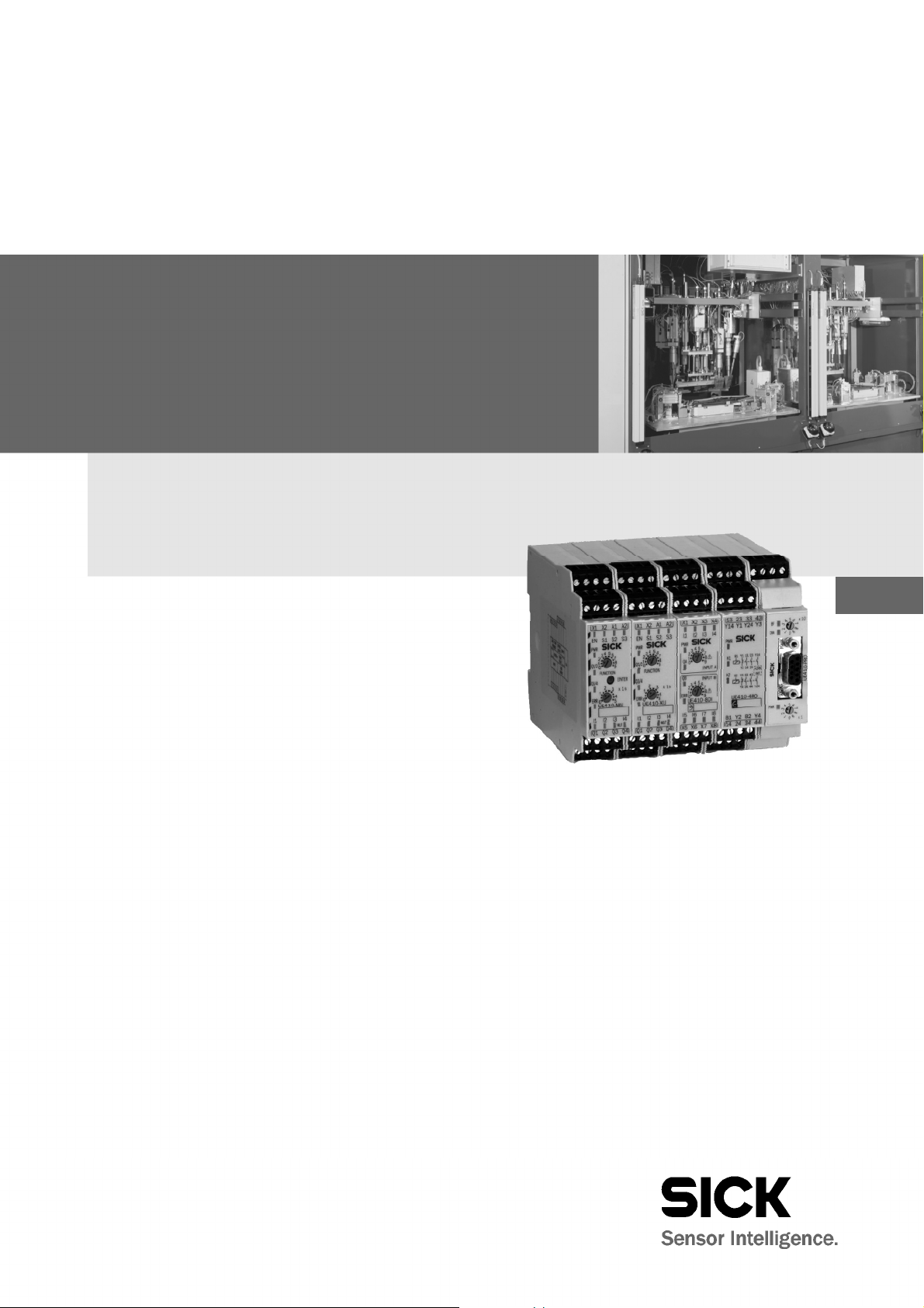
Fig.1:
Controls and statu
s
Tab.28:
Indication LED
Tab.29:
Address switch
Flexi Classic Gateways
PROFIBUS DP Gateway
4 PROFIBUS DP Gateway
The following Flexi Classic gateways can be used for PROFIBUS DP:
• UE410-Pro3, UE410-Pro4
4.1 Interfaces and operation
4.1.1 Controls and status indicators
indicators UE410-PRO
UE410-PRO
UE410-PRO
Notes
Display Meaning
PWR (green) Supply volt ag e present
BF (red)
DIA (red) No function (not used)
Switch/button Function
× 10
× 1
No bus connection, fieldbus cable break or master is not (or no
longer) writing to the bus
Address switch 1
10-position rotary switch for setting the module address
(tens)
Address switch 2
10-position rotary switch for setting the module address
(units)
• The occurrence of random or systematic errors in the gateway or in its o peration does
not result in the degradation of the safety functions on t he Flexi Classic system.
• With the operating voltage switched on, no gateways are allowed to be disconnected
from the Flexi Classic system or added by plugging in.
• The PROFIBUS master cannot overwrite the address set.
• A modified address setting only becomes effective after switching off and switching on
the Flexi Cla ssic system.
8011834/YT28/2016-03-15 © SICK AG • Industrial Safety Systems • Germany • All rights reserved 27
Subject to change without notice
Page 28
Chapter 4 Operating Instructions
Tab.30: Application
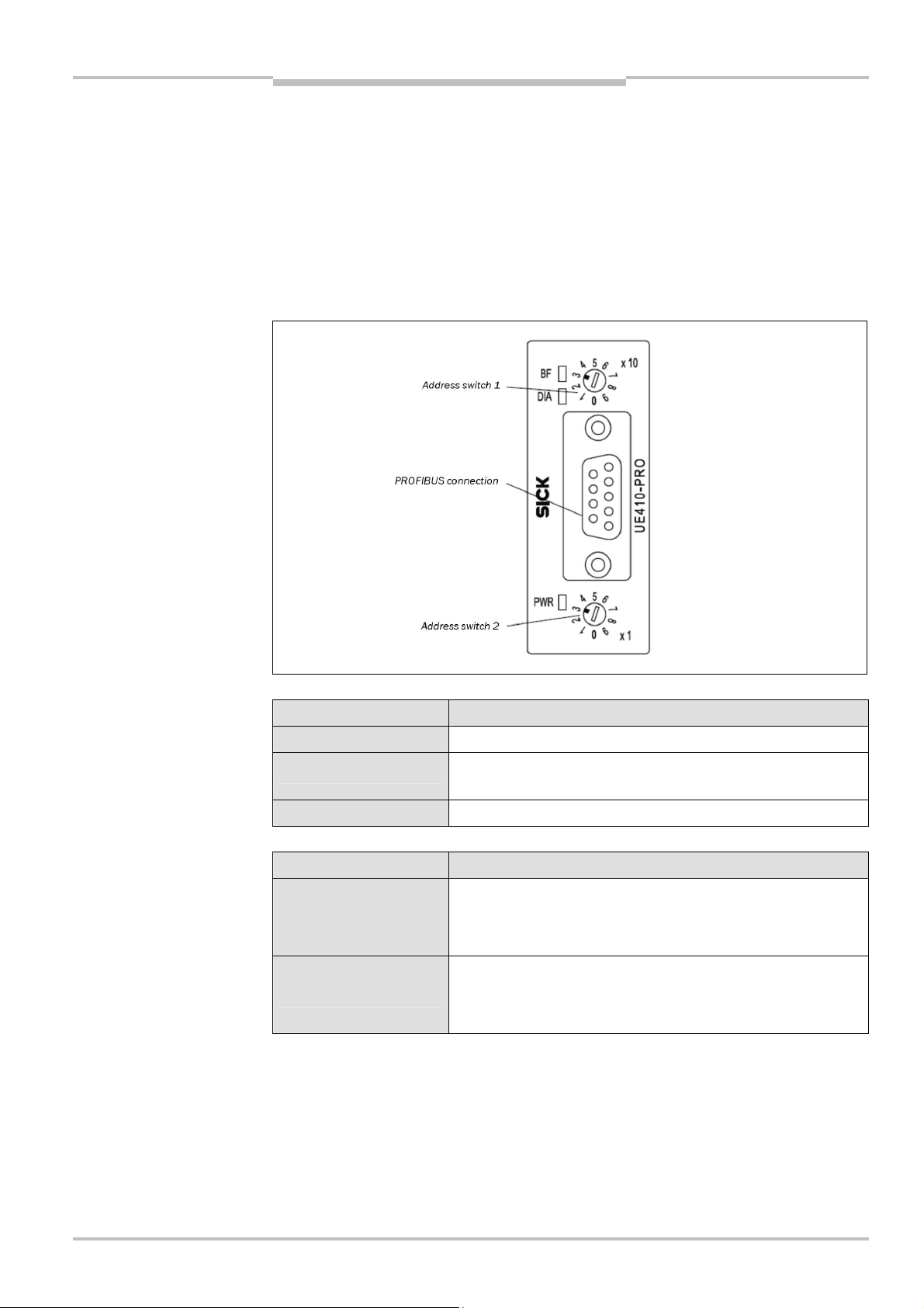
Fig.2:D-
Sub socket and plug
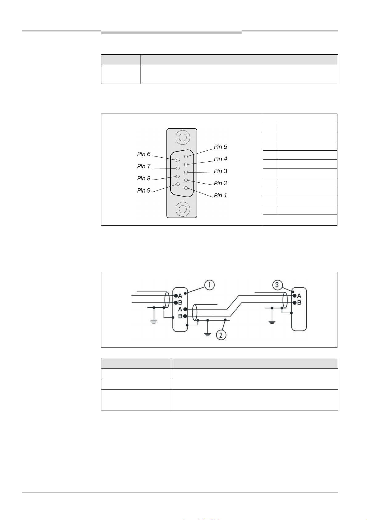
Fig.3:
Bus cable UE410
-
PRO
Tab.31:
Explanatio
n bus
PROFIBUS DP Gateway
Flexi Classic Gateways
4.1.2 Application diagnostic outputs UE410-PRO
diagnostic outputs
pin assignments UE410-PRO
Assignment Description
X1-X4 Short circuit and overload detecting control outputs (PNP) supplied via Flexi
Classic system
4.1.3 Plug assignment
The connection to the PROFIBUS-DP fieldbus is made using a 9-pin Sub-D socket.
Pin Description
1 SHLD
2 NC
3 RxD/TxD-P
4 CNTR-P
5 GND-EXT
6 +5V-EXT
7 NC
8 RxD/TxD-N
9 CNTR-N (GND-EXT)
4.1.4 Bus cable
cable UE410-PRO
The bus topology for PROFIBUS-DP is a linear structure comprising a screened, twisted
2Fcore cable with active bus termination at both ends. The possible bus lengths are 100 m
at 12 MBit/s up to 1,200 m at 94 KBit/s.
Position Description
1
2
3
PROFIBUS user grey
Screened bus cable
PROFIBUS termination yellow
(with integrated terminating resistors)
28 © SICK AG • Industrial Safety Systems • Germany • All rights reserved 8011834/YT28/2016-03-15
Subject to change without notice
Page 29

Operating Instructions Chapter 4
Tab.32:
Cable parameters
Tab.33:
Maximum cable
Flexi Classic Gateways
PROFIBUS DP Gateway
4.1.5 Cable parameters
The properties of the bus cable are specified in EN 50170 as cable type A.
UE410-PRO
Property Value
Characteristic impedance
Capacitance per unit length
Loop resistance
Core diameter
Core cross-section
135-165 (at a frequency of 3-20 MHz)
< 30 pF/m
T 110 /km
> 0.64 mm
> 0.34 mm
2
With these cable parameters, the following maximum physical sizes are possible for a bus
segment:
lengths UE410-PRO
Baud rate (Kbit/s) Max. cable length (m)
9.6 1200
19.2 1200
93.75 1200
187.5 1000
500 400
1500 200
12000 100
4.1.6 Data transmission rate
The data transmission rate is set automatically.
The maximum baud rate is 12 MBit/s.
8011834/YT28/2016-03-15 © SICK AG • Industrial Safety Systems • Germany • All rights reserved
Subject to change without notice
29
Page 30

Chapter 4 Operating Instructions
Tab.34:
Possible planning
PROFIBUS DP Gateway
Flexi Classic Gateways
4.2 Planning
4.2.1 GSD file
In the normal case the UE410-PRO is used on a DP master that looks up the device
characteristics in the so-called GSD file.
You will find the GSD file for PLC interfacing with Profibus support in the Internet at
www.ue410flexi.com.
The UE410-PRO provides at least 4 bytes of input data and 4 bytes of output data (2 bytes
of which are unused). The GSD identifier for this I/O module SCB1 Basic1 4 Byte in/out is
33h. If the DP master is configured with the aid of a GSD file, it is imperative this module is
included in the planning.
The UE410-PRO can provide further I/O modules as an option if included in the DP master
during the planning by the user. For more detailed diagnostics, the I/O module SCB2
Basic2 2 Byte in with the GSD identifier 11h is available.
A further optional I/O module is DIAG 10 Byte in with the GSD identifier 19h. Up to 4 units
of this module can be included in the planning.
There are therefore six possible ways of planning the UE410-PRO. Shown is the order of
the GSD identifiers for each plan:
UE410-PRO
Possible
planning
SCB1 Basic1
4 Byte in/out
SCB2 Basic2
2 Byte in
DIAG
10 Byte in
MED
13 Byte in
1 33h
2 33h 11h
3 33h 11h 19h
4 33h 11h 1Ch
5 33h 11h 19h 1Ch
30 © SICK AG • Industrial Safety Systems • Germany • All rights reserved 8011834/YT28/2016-03-15
Subject to change without notice
Page 31

Operating Instructions Chapter 4
Tab.35:
Format of the diag
-
Flexi Classic Gateways
PROFIBUS DP Gateway
Design variant 4 is shown in the following table.
nostics data UE410-PRO
I/O modules GSD identifier
SCB1 Basic1 4 Byte in/out
Contains configuration checksum
and basic diagnostics
Contains extended basic diagnostics
DIAG 10 Byte in
Depending on the REQ-ID this
module contains
10 bytes diagnostics with varying
content
MED 13 Byte
Contains the input signals for all Flexi
Classic modules fitted
E.g. MED7 contains the input data
for module 7
ID: 33h (mandatory)
ID: 11h (optional)
ID: 19h (optional)
ID: 1Ch (optional)
Data direction
Read Write
CRC1 DIG-OUT
CRC2 REQ-ID
BAS1 Reserved
BAS2 Reserved
BAS3 – SCB2 Basic2 2 Byte in
BAS4 –
B1 –
B2 –
: :
B10 –
MED1 –
MED2 –
: :
MED13 –
See also section 3.2 “Status information of all Flexi Classic gateways (system bytes)”.
If a DP master is used that does not send any planning data to the UE410-PRO (e.g.
PROFIBUS Master Simulator PR-MSV01 (6022458) from SICK in the “Start without GSD
file” mode), the UE410-PRO supplies the diagnostic data as for plan 5 (see Tab. 34 on
page 30).
4.2.2 Documenting with PROFIBUS-DP Master Simulator
You can save diagnostics data on a PC with the aid of the PROFIBUS-DP Master Simulator
(see section 11.7 “Accessories/spare parts”) and the file flexi_config_list.xls.
For this purpose, connect a data cable between PC, PROFIBUS-DP Master Simulator and
UE410-PRO (RS-232-D-Sub). Install the file “flexi_config_list.xls” on your PC, Excel 2000 or
later must be installed on the PC.
You can then save and document the diagnostics data and settings for the overall system
with the aid of your PC.
We also refer you to our homepage on the Internet at
http://www.ue410flexi.com
There you will find the following files for download:
GSD file
flexi_config_list.xls
4.2.3 Diagnostics data UE410-PRO
You will find the description of the status bytes in the section “Status information of all
Flexi Classic gateways (system bytes)”.
8011834/YT28/2016-03-15 © SICK AG • Industrial Safety Systems • Germany • All rights reserved
Subject to change without notice
31
Page 32

Chapter 5 Operating Instructions
Fig.4:
Controls and status
Address switch 1
DIP switch
CANopen
Address switch 2
1000
Baud rate kBit/s
800
500
250
125
CANopen Gateway
Flexi Classic Gateways
5 CANopen Gateway
he following Flexi Classic gateways can be used for CANopen:
T
UE410-CAN3, -CAN4
5.1 Interfaces and operation
5.1.1 Control and status indicators
indicators UE410-CAN
connection
32 © SICK AG • Industrial Safety Systems • Germany • All rights reserved 8011834/YT28/2016-03-15
Subject to change without notice
Page 33

Operating Instructions Chapter 5
Tab.36:
Indication LE
D
Tab.37:
Address switch
Tab.38:
Application
Flexi Classic Gateways
CANopen Gateway
UE410-CAN
Display Meaning
PWR (green) Supply voltage present
NS
Green flashing CANopen status: Pre-Operational (SDO data exchange)
Green CANopen status: Operational (PDO + SDO Data Exchange)
Red flashing Node-guarding Time out (the NMT master is no longer monitoring
the slave).
MS
Green flashing After cable break or node guarding failure
Green CANopen is ready
Red flashing fast CAN status: Bus Off
No error-free access to the CAN-BUS possible
Possible errors:
• wrong baud rate selected
• eiring error in the network
• another CAN controller in the network has a hardware error
• module faulty
UE410-CAN
diagnostic outputs
Switch/button Function
Address switch 1
× 10
× 1
10-position rotary switch for setting the module address
(tens)
Address switch 2
10-position rotary switch for setting the module address
(units)
The occurrence of random or systematic errors in the gateway or in its operation does
not result in the degradation of the safety functions on the Flexi Classic system.
With the operating voltage switched on, no gateways are allowed to be disconnected
from the Flexi Classic system or added by plugging in.
The CANopen master cannot overwrite the address set.
A modified address setting only becomes effective after switching off and switching on
the Flexi Classic system.
5.1.2 Application diagnostic outputs UE410-CAN
Assignment Description
X1-X4 Short circuit and overload detecting control outputs (PNP) supplied via Flexi
Classic system
8011834/YT28/2016-03-15 © SICK AG • Industrial Safety Systems • Germany • All rights reserved
Subject to change without notice
33
Page 34

Chapter 5 Operating Instructions
Fig.5:
Open style connector
Fig.6:
Bus cable
Terminating
CANopen Gateway
Flexi Classic Gateways
5.1.3 Plug assignment
The connection to the CANopen fieldbus is made using a 5-pin open style connector.
and pin assignment
UE4100CAN
Pin Description
5 V+ CAN_V+ Voltage supply
4 H CAN_H CAN High
3 DR (CAN_SHILD) Screen connection
(optional)
2 L CAN_L CAN Low
1 V– CAN_GND Ground/0V
5.1.4 Bus cable
Note
CANopen is based on a linear topology with screened, twisted pair 2-core cable and terminating resistors at both ends of the bus. The screen is connected to ground at both ends.
The transmission rate, depending on the network length, is between 10 kBit/s (>1000 m)
and 1 MBit/s (25 m).
Node
resistance
It is not necessary to connect a voltage supply (pin 1/5) to the UE410-CAN.
34 © SICK AG • Industrial Safety Systems • Germany • All rights reserved 8011834/YT28/2016-03-15
Subject to change without notice
Page 35

Operating Instructions Chapter 5
Tab.39: Format of diagnos
-
Flexi Classic Gateways
CANopen Gateway
5.2 Planning
5.2.1 EDS file
The device characteristics are described using the Electronic Data Sheet (EDS), which
every standard bus configuration tool uses.
5.2.2 PCS
With so-called PDO linking (the arbitrary assignment of CAN identifiers to the individual
ProcessDataObjects), CANopen makes it possible to setup multi-master networks.
However, if the CANopen devices are to be controlled from a central instance, the CAN
identifiers to be used can be restricted to a pre-defined set, the Predefined Connection Set
PCS. Then the CAN controller only accepts CAN messages addressed to the related device.
A CANopen device (e.g. the UE410-CAN Gateway) makes its inputs and outputs available
as “communication objects” that can be addressed or sent using the PCS identifiers.
The PCS operating mode provides two crucial advantages:
The CANopen-PCS protocol can be implemented on a controller or a PC without major
effort. Planning is significantly simplified, as within the PCS all CAN identifiers are
unique in relation to the node address. As a result, time and costs for setting up simple
networks are reduced.
Due to the PCS addressing, the UE410-CAN is insensitive particularly to high bus loads
and ensures vary fast I/O communication. With synchronous communication, response
times of approx. 300 Vs are achieved. All four reply PDOs are sent in a period < 1 ms
after receipt of a Sync (baud rate = 1000 KBit/s).
The PCS comprises 2 broadcast objects SYNC and NMT and a total of 12 peer-to-peer
objects. Each of these objects has a unique 11-bit CAN identifier that comprises a function
code and a device address. The device address for the broadcast objects is 0, for the other
objects 1…127.
tics data
5.2.3 Format of diagnostics data
Object CAN identifier
NMT 00h Network management
SYNC 80h Sync message
EMERGENCY 081h..0FFh Status message
TxPDO1 181h..1FFh
RxPDO1 201h..27Fh Process data object 1 (see following page)
TxPDO2 281h..2FFh Process data object 2 (see following page)
RxPDO2 301h..37Fh Process data object 2 (see following page)
TxPDO3 381h..3FFh Process data object 3 (see following page)
RxPDO3 401h..47Fh Process data object 3 (see following page)
TxPDO4 481h..4FFh Process data object 4 (see following page)
RxPDO4 501h..57Fh Process data object 4 (see following page)
TxSDO 581h..5FFh Sending service data
RxSDO 601h..67Fh Receiving service data
NMT-ErrorControl 701h..77Fh Node-guarding
Meaning
Process data object 1 (see following page)
(from the viewpoint of the CANopen server: Tx=Transmit, Rx=Receive)
8011834/YT28/2016-03-15 © SICK AG • Industrial Safety Systems • Germany • All rights reserved
Subject to change without notice
35
Page 36

Chapter 5 Operating Instructions
Tab.40:
Transmit PDO
T
ab.41:
Transmit PDO
CANopen Gateway
Flexi Classic Gateways
5.2.4 TxPDO1
Transmit PDO (process data object) 1.
(process data object) 1
CAN-ID DLC DATA
181..1FF 8 BAS1 MQD1 MED1 MED2 MED3 MED4 MED5 MED6
Mapping 3100.2 3101.2 3101.1 3102.1 3103.1 3104.1 3105.1 3106.1
BAS1 Group error bits
MQD1 Output data module 1 (UE410-MU…)
MED1 Input data module 1 (UE410-MU…)
MED2 Input data module 2
MED3 Input data module 3
MSD4 Input data module 4
MED5 Input data module 5
MED6 Input data module 6
See also section 3.2 “Status information of all Flexi Classic gateways (system bytes)”.
(process data object) 2
5.2.5 TxPDO2
Transmit PDO (process data object) 2.
CAN-ID DLC DATA
281..2FF 7 MED7 MED8 MED9 MED10 MED11 MED12 MED13 -
Mapping 3107.1 3108.1 3109.1 310A,1 310B,1 310C,1 310D,1 -
MED7
MED8
MED9
MED10
MED11
MED12
MED13
Input data module 7
Input data module 8
Input data module 9
Input data module 10
Input data module 11
Input data module 12
Input data module 13
- Unused
See also section 3.2 “Status information of all Flexi Classic gateways (system bytes)”.
36 © SICK AG • Industrial Safety Systems • Germany • All rights reserved 8011834/YT28/2016-03-15
Subject to change without notice
Page 37

Operating Instructions Chapter 5
Tab.42:
Transmit PDO
Tab.43:
Transmit PDO
Flexi Classic Gateways
CANopen Gateway
5.2.6 TxPDO3
Transmit PDO (process data object) 3.
(process data object) 3
CAN-ID DLC DATA
381..3FF 8 MQD2 MQD3 MQD4 MQD5 MQD6 MQD7 MQD8 MQD9
Mapping 3102.2 3103.2 3104.2 3105.2 3106.2 3107.2 3108.2 3109.2
MQD2 Output data module 2
MQD3 Output data module 3
MQD4 Output data module 4
MQD5 Output data module 5
MQD6 Output data module 6
MQD7 Output data module 7
MQD8 Output data module 8
MQD9 Output data module 9
See also section 3.2 “Status information of all Flexi Classic gateways (system bytes)”.
(process data object) 4
5.2.7 TxPDO4
Transmit PDO (process data object) 4.
CAN-ID DLC DATA
481..4FF 4 MQD10 MQD11 MQD12 MQD13 - - - -
Mapping 310A,2 310B,2 310C,2 310D,2 - - - -
MQD10
MQD11 Output data module 11
MQD12
MQD13
Output data module 10
Output data module 12
Output data module 13
-
Unused
-
Unused
-
Unused
- Unused
See also section 3.2 “Status information of all Flexi Classic gateways (system bytes)”.
8011834/YT28/2016-03-15 © SICK AG • Industrial Safety Systems • Germany • All rights reserved
Subject to change without notice
37
Page 38

Chapter 5 Operating Instructions
Tab.44:
Receive PDO
Tab.45:Network
Tab.46:
Network
CANopen Gateway
Flexi Classic Gateways
5.2.8 RxPDO1
Receive PDO (process data object) 1
(process data object) 1
CAN-ID DLC DATA
201..27F 1 DIG-OUT - - - - - - -
Mapping 6200.1 - - - - - - -
management for one NMT
slave with address N
management for all NMT
slaves
DIG-OUT
Digital outputs on the diagnostics module
- Unused
5.2.9 NMT Network Management
The NMT objects are used to start, stop or initialise CANopen devices. For this purpose a
device in the CANopen network must take over the role of the NMT master. All devices are
regarded as NMT slaves. NMT services are broadcast services, i.e. the slaves do not generate a reply.
For an NMT slave with address N:
CAN-ID DLC DATA
00h 2 OP N
For all NMT slaves:
CAN-ID DLC DATA
00h 2 OP 0
OP NMT Operation 80h = Change to “Pre-Operational”
01h = Change to “Operational”
02h = Change to “Prepare/Stopped”
81h = Change to “Reset Node”
82h = Change to “Reset Communication”
5.2.10 Pre-Operational
After booting an NMT slave automatically enters the “Pre-Operational” state. In this state,
communication is allowed with the SDO, but not with the PDO. The NMT slave can be
changed from another state to this state.
5.2.11 Operational
The “Operational” state is reached from the “Pre-Operational” state. In this state communication via PDO is possible and the CANopen slave reacts to SYNC.
Note
TPDOs with the transmission mode 255 are sent once on the transition to the NMT status
“Operational”, so that the NMT master is informed of the current input configuration.
5.2.12 Prepared/Stopped
In this state, communication is not possible with SDO or PDO, there is also no reaction to
SYNC.
5.2.13 Reset node
This NMT service triggers a re-initialisation of the CANopen functionality in the NMT slave.
38 © SICK AG • Industrial Safety Systems • Germany • All rights reserved 8011834/YT28/2016-03-15
Subject to change without notice
Page 39

Operating Instructions Chapter 5
Tab.47:
Polling inputs using
Tab.48:
Request from NMT
Tab.49:
Respons
e from
Tab.50:
Remote
Flexi Classic Gateways
CANopen Gateway
5.2.14 Reset communication
This NMT service triggers a re-initialisation of the CANopen functionality in the NMT slave;
the toggle bit for the node guarding is set to 0.
5.2.15 SYNC
The Sync object causes all TxPDOs for a CANopen slave to be sent. It is therefore possible
to poll the inputs on the slave using Sync.
SYNC
CAN-ID DLC DATA
80h 0
The slave sends all input values when this message arrives. All TxPDOs are sent. Also the
unused TxPDO1 to TxPDO4 are sent with the length 0 (DLC=0).
To ensure the slave automatically sends the actual input values on the receipt of a Sync,
the transmission type for the related PDOs must be set to 0 (acyclic, synchronous). This is
the default. In addition, the operating mode must be set to “Operational”.
For the TxPDO it is possible to change the transmission type using the SDOs 1800..1803
(PDO communication parameter) and the sub-object 2. Allowed are the types:
acyclic/synchronous = 0
cyclic/synchronous = 1..240
acyclic by device profile = 255 (only for TPDO1-4, digital inputs)
master:
slave:
Transmission Request
5.2.16 Node-guarding
An NMT master (e.g. a PLC with integrated CANopen master) uses the object NMT-ErrorControl to detect the failure of an NMT slave with the address N. The NMT slave replies
within the node guarding time to the request from the NMT master. The node guarding
time must be monitored by the NMT master.
Request from NMT master:
CAN-ID RTR DLC DATA
700h + N 1 0
Response from slave:
CAN-ID DLC DATA
700h + N 0 BYTE1
The NMT master sends a CAN message with the identifier <700h + node-id> and RTR bit
set (Remote Transmission Request). The slave then sends a status byte B1 with the
following contents:
Bit Meaning
7 Toggle bit, changes value between two sequential requests
6..0 NMT-Status 4 = Stopped
5 = Operational
127 = Pre-Operational
8011834/YT28/2016-03-15 © SICK AG • Industrial Safety Systems • Germany • All rights reserved
Subject to change without notice
39
Page 40

Chapter 5 Operating Instructions
Tab.52:
Write SDO
Tab.53:
Confirmation SDO
CANopen Gateway
Flexi Classic Gateways
5.2.17 Emergency
A CANopen slave with the address N sends an Emergency message to inform the other
devices about an error state.
Tab. 51: Emergency
messages
CAN-ID DLC DATA
80h + N 8 ErrL ErrL Err-Reg
ErrL, ErrH Emergency error code,
16 bit low byte/high
byte
Err-Reg Error register,
CANopen object 1001h
8111h =
1001h =
CAN-Controller overrun (only if internal
64-byte hardware fifo overflows)
Generic error, if an error has occurred
on the Flexi Classic. In this case the
error list in object 1003h should be
checked.
5.2.18 SDO communication
SDOs are Service Data Objects. They contain a wide variety of data. These include, among
other items, data on the planning or input and output data. Unlike the PDO communication,
each reception of an SDO is answered at protocol level.
In this CANopen-PCS implementation the following protocols are supported:
SDO Download expedited (writing an SDO)
SDO Upload expedited (reading an SDO)
Upload SDO Segment Protocol (segmented reading of an SDO)
5.2.19 SDO Download expedited (Write SDO)
The client sends Request message to server N. The index and the sub-index for the SDO to
be written are coded in this message. In addition, the request also contains 4 data bytes.
Write:
CAN-ID DLC DATA
600h + N 8 23h SDO_L SDO_H SUB B1 B2 B3 B4
Confirmation:
CAN-ID DLC DATA
580h + N
60h SDO_L SDO_H SUB BYTE 1 BYTE 2 BYTE 3 BYTE 4
8
40 © SICK AG • Industrial Safety Systems • Germany • All rights reserved 8011834/YT28/2016-03-15
Subject to change without notice
Page 41

Operating Instructions Chapter 5
Tab.54:
Write SDO
Tab.55:
Confirmat
ion SDO
Fig.7:
Standard objects SDO
Flexi Classic Gateways
CANopen Gateway
5.2.20 SDO Upload expedited (Read SDO)
The client requests the contents of an SDO with a Request message to server N. The index
and sub-index for the SDO to be read are coded in this message.
CAN-ID DLC DATA
600h + N
40h SDO_L SDO_H SUB BYTE 1 BYTE 2 BYTE 3 BYTE 4
8
Confirmation:
CAN-ID DLC DATA
580h + N 43h SDO_L SDO_H SUB BYTE 1 BYTE 2 BYTE 3 BYTE 4
5.2.21 Object list SDO
Every CANopen device manages its SDOs in an object list. The complete object list is formally described in an EDS file. Many CANopen tools can read this EDS file and as a result
know the object characteristics of the CANopen device.
In the following, all objects for the UE410-CAN Gateway are shown combined into groups.
8011834/YT28/2016-03-15 © SICK AG • Industrial Safety Systems • Germany • All rights reserved
Subject to change without notice
41
Page 42

Chapter 5 Operating Instructions
Fig.8:
Configuration objects
flexi
flexi
CANopen Gateway
Flexi Classic Gateways
5.2.22 Configuration objects
The configuration data described in the data index are combined here to a data structure.
The complete configuration information for each module fitted is available at any time
ithout request via the REQ-ID.
w
The SDO 3201 contains the configuration data for module 1 (e.g. UE410-MU). The SDO
3202 contains the data for the 2nd module etc. up to the SDO 320D, which contains the
data for the 13th module. There are only as many modules in the object list for the diagnostics module as there are modules fitted. If less than 13 modules are fitted, the related
SDOs do not exist.
The individual bytes written to the data index are partially combined in the SDO 320x to
words/double words (Little Endian mode).
SW-VERSION = USIGN16
CRC CODE = USIGN32
MOD-ID/FUNCTION/KONF = USIGN8
flexi
flexi
flexi
flexi
flexi
flexi
flexi
flexi
flexi
flexi
flexi
42 © SICK AG • Industrial Safety Systems • Germany • All rights reserved 8011834/YT28/2016-03-15
Subject to change without notice
Page 43

Operating Instructions Chapter 5
Fig.9:
Input/output objects
Fig.10:
Module list objects
Flexi Classic Gateways
CANopen Gateway
5.2.23 Input/output objects
On writing to the REQ-ID (SDO 6200,2), the reply data are made available in B1..B10, as
described in the data index. The SDO 6200,1 contains the 4 digital outputs X1..X4.
flexi
5.2.24 Module list objects
The module list objects are templates for the dynamic expansion of the SDO 1027. This
SDO contains a list of the module identifiers for the modules fitted.
UE410-MU/MM...
UE410-MU/MM...
UE410-XU/XM...
UE410-XU/XM...
UE410-8DI/MDI
UE410-8DI/MDI
Example of a module list:
UE410-MU/MM...
UE410-XU/XM...
The module structure is 1x UE410-MU/MM + 1x UE410-XU/XM. A diagnostics device
would first read in 1027,0. The result (=2) is used to read exactly 2 further SDOs from
which then the module identifier and the arrangement of the modules is to be found.
8011834/YT28/2016-03-15 © SICK AG • Industrial Safety Systems • Germany • All rights reserved
Subject to change without notice
43
Page 44

Chapter 5 Operating Instructions
Fig.11:
Mapping/
Communi
-
CANopen Gateway
Flexi Classic Gateways
5.2.25 Mapping/communication parameter objects
The communication characteristics and the default mappings for the RPDO1 and the
TPDO1+4 are described in these SDOs. You will find more detailed information on these
DOs in DS301 V4.02.
S
Variable mapping is not supported. For this reason the mapping SDOs are read-only. The
static mapping for TxPDO1, TxPDO4 and RxPDO1 is described in the SDOs 1600, 1A00
and 1A03.
cation parameter objects
44 © SICK AG • Industrial Safety Systems • Germany • All rights reserved 8011834/YT28/2016-03-15
Subject to change without notice
Page 45

Operating Instructions Chapter 5
Fig.12: Flexi
-
Classic
-
ERROR
Flexi Classic Gateways
CANopen Gateway
5.2.26 Flexi-Classic-ERROR list object
This SDO contains a list of the ERRORs that have occurred in the Flexi Classic system. The
list has 13 entries. The number of entries corresponds to the maximum number of Flexi
lassic modules in the system.
C
list object
Each entry contains a 4-byte error code for VK1 and VK2 for a module. The most significant 2 bytes contain the error code for VK1 (see MFCODE1). The least significant 2 bytes
contain the error code for VK2 (see MFCODE2).
8011834/YT28/2016-03-15 © SICK AG • Industrial Safety Systems • Germany • All rights reserved
Subject to change without notice
45
Page 46

Chapter 5 Operating Instructions
Fig.13:
Status objects
CANopen Gateway
Flexi Classic Gateways
5.2.27 Status objects
The diagnostics data written to the data index are combined here to form a data structure.
The complete status information for each module fitted is available at any time without
equest via the REQ-ID.
r
The SDO 3100 combines the diagnostics data CRC1, CRC2, BAS1..BAS4. The SDO 3101
contains the status data for module 1 (main unit). The SDO 3102 contains the data for the
2nd module etc. up to SDO 310D, which contains the data for the 13th module. There are
only as many modules in the object list for the diagnostics module as there are modules
fitted. If less than 13 modules are fitted, the related SDOs do not exist.
The individual bytes written to the data index are partially combined in the SDO 310x to
word/double word (Little Endian mode):
MFCLASS1+MFCODE1 = USIGN16
MFCLASS2+MFCODE2 = USIGN16
flexi
flexi
flexi
flexi
flexi
flexi
flexi
flexi
flexi
flexi
flexi
flexi
flexi
flexi
46 © SICK AG • Industrial Safety Systems • Germany • All rights reserved 8011834/YT28/2016-03-15
Subject to change without notice
Page 47

Operating Instructions Chapter 6
Fig.14:
Controls and status
Address switch 1
DIP switch
DeviceNet
Address switch 2
DIP switch
125
kBit/s
250 kBit/s
500 kBit/s
Flexi Classic Gateways
DeviceNet Gateway
6 DeviceNet Gateway
he following Flexi Classic gateways can be used for DeviceNet:
T
UE410--DEV3, -DEV4,
6.1 Interfaces and operation
6.1.1 Characteristics of the DeviceNet implementation
group 2 Only Server (fragmented)
acknowledge Handling
I/O messaging (polled, COS/CYCLIC) also fragmented
baud rate can only be adjusted using DIP switch (125 KBit/s, 250 KBit/s, 500 KBit/s)
6.1.2 Controls and status indicators
indicators UE410-DEV
connection
Data transmission rates
8011834/YT28/2016-03-15 © SICK AG • Industrial Safety Systems • Germany • All rights reserved
Subject to change without notice
47
Page 48

Chapter 6 Operating Instructions
Tab.56:
Indication LED
Tab.57:
Address switch
Tab.58:
Application
DeviceNet Gateway
Flexi Classic Gateways
UE410-DEV
UE410-DEV
Display Meaning
PWR (green) Supply voltage present
NS (off)
NS (green flashing)
NS (green)
NS (red)
MS (green flashing)
MS (green) UE410-DEV is ready and the PLC is in the Run mode.
MS (red flashing) The internal EEPROM has an error.
Display Meaning
X 10 Address switch 1 (possible bus addresses 0-63)
X 1 Address switch 2 (possible bus addresses 0-63)
“DUP MAC Check” not completed successfully.
UE410-DEV operating on the bus, but has not yet been detected by a
master or no logical connection has been established to the UE410DEV.
UE410-DEV has been detected by a master and a logical connection
has been established to the UE410-DEV.
During “DUP MAC Check”, UE410-DEV has found a different device
with the same MAC ID.
The fieldbus connection has been interrupted. The remote PLC is in
the stop mode. The master is currently attempting to establish the
connection to the UE410-DEV. The planned I/O size in the scan list is
incorrect (Error 77 on the scanner).
10-position rotary switch for setting the module address (tens)
10-position rotary switch for setting the module address (units)
diagnostic outputs
Notes
DIP switch 4-pole DIP switch for setting the baud rate
DIP 3 and 4 are not used.
If a larger address is selected, address 63 is active.
The occurrence of random or systematic errors in the gateway or in its operation does
not result in the degradation of the safety functions on the Flexi Classic system.
With the operating voltage switched on, no gateways are allowed to be disconnected
from the Flexi Classic system or added by plugging in.
The DeviceNet master cannot overwrite the address set.
A modified address setting only becomes effective after switching off and switching on
the Flexi Classic system.
6.1.3 Application diagnostic outputs UE410-DEV
Assignment Description
X1-X4 Short circuit and overload detecting control outputs (PNP) supplied via Flexi
Classic system
48 © SICK AG • Industrial Safety Systems • Germany • All rights reserved 8011834/YT28/2016-03-15
Subject to change without notice
Page 49
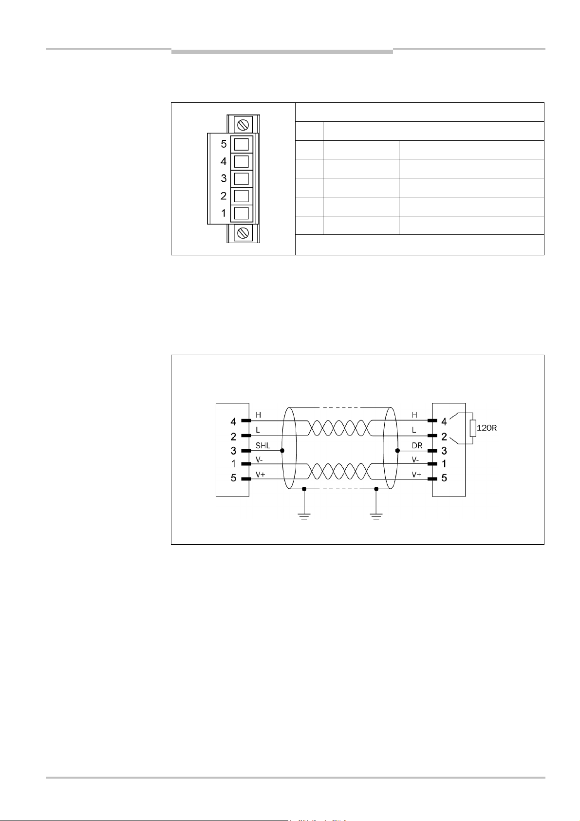
Operating Instructions Chapter 6
Fig.15:
Open style connector
Flexi Classic Gateways
DeviceNet Gateway
6.1.4 Plug assignment
The connection to the DeviceNet fieldbus is made using a 5-pole open style connector.
and pin assignment UE410DEV
Pin Description
5
V+ +24VDC Voltage supply
4
H DeviceNet DeviceNet High
3
SHLID Screen connection (optional)
2
L DeviceNet DeviceNet Low
1
V– 0VDC GND/0V
6.1.5 Bus cable
The bus topology of the DeviceNet is linear, the connection of the up to 64 nodes is made
using an un-branched bus cable (trunk line) with terminating resistor at both ends and
short stubs (drop lines). A screened, twisted-pair 2-core cable is used. The cable length
depends on the data transmission rate used and is from 100 m at 500 KBit/s to 500 m at
125 KBit/s.
Fig. 16: Bus cable UE410DEV
Node Termination
8011834/YT28/2016-03-15 © SICK AG • Industrial Safety Systems • Germany • All rights reserved
Subject to change without notice
49
Page 50

Chapter 6 Operating Instructions
Tab.59:
Format of the
DeviceNet Gateway
Flexi Classic Gateways
6.2 Planning
6.2.1 EDS file
diagnostics data UE410-DEV
The EDS (Electronic Data Sheet) is read once into the device database for the DeviceNetManager
For planning use the DeviceNetManager
TM
. For this purpose the menu command “Utilities/Read EDS Files” is to be used.
M
T
from Allen Bradley. You will find the EDS file in
the Internet at www.ue410flexi.com.
Byte
1 CRC1 DIG-OUT
2 CRC1 REQ-id
3 BAS1 -
4 BAS2 -
5 BAS3 -
6 BAS4 -
7
8
9
10
11
12
13
14
15
16
Data direction
Read Write
B1 -
B2 -
B3 -
B4 -
B5 -
B6 -
B7 -
B8 -
B9 -
B10 -
6.2.2 Diagnostics data UE410-DEV
You will find the system and diagnostics data in the section 3.2 “Status information of all
Flexi Classic gateways (system bytes)”.
50 © SICK AG • Industrial Safety Systems • Germany • All rights reserved 8011834/YT28/2016-03-15
Subject to change without notice
Page 51
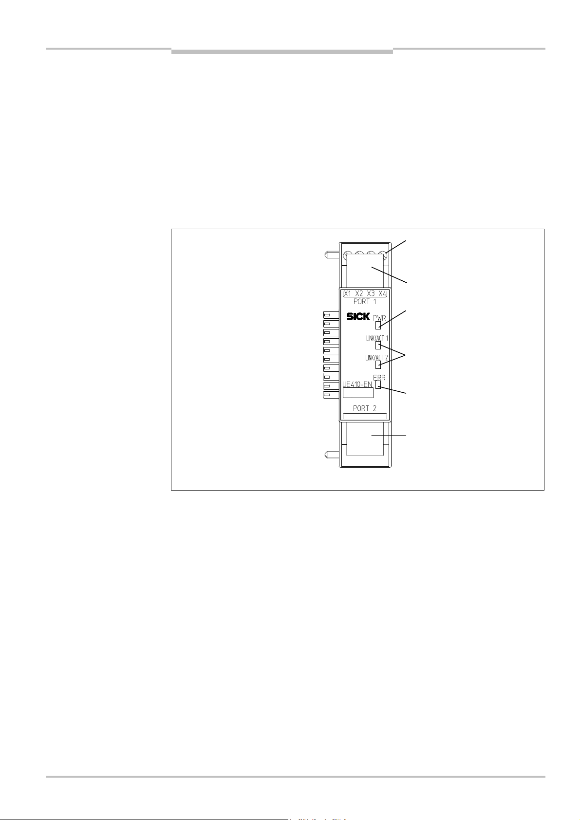
Operating Instructions Chapter 7
Fig.17:
Interfaces and
Terminals of digital control
RJ45 Ethernet socket
RJ45 Ethernet socket
LED power supply (green)
LED network activity for
LED Error (red/green)
Flexi Classic Gateways
Modbus/TCP Ethernet Gateway
7 Modbus/TCP Ethernet Gateway
he following Flexi Classic gateway can be used for Modbus/TCP: UE410-EN3
T
7.1 Interfaces and operation
The UE410-EN is equipped with four digital control outputs X1–X4.
The UE410-EN is equipped with an integrated 3-port switch for connection with the Ethernet network. Two RJ45 sockets are available for the connection. The switch functionality
allows the UE410-EN to be used for connection to another Ethernet component (e.g. connection to a notebook) without having to interrupt the Ethernet connection to the network.
display elements of the
UE410-EN
outputs X1–X4
Ethernet port 1 or 2 (green)
8011834/YT28/2016-03-15 © SICK AG • Industrial Safety Systems • Germany • All rights reserved
Subject to change without notice
51
Page 52

Chapter 7 Operating Instructions
Tab.60:
Meaning of the LED
Modbus/TCP Ethernet Gateway
Flexi Classic Gateways
displays
Note
LED Meaning
No power supply PWR
Green Power supply switched on
LINK/ACT 1
LINK/ACT 2
No Ethernet connection
Green Ethernet connection active, no data transmission
Green Ethernet connection active, data transmission
No power supply ERR
Green Gateway operating, no error message, at least one
Ethernet connection exists
Green Gateway operating, valid IP address assigned, configu-
ration is valid, but no Ethernet connection established.
All data sets are deactivated
Red No flex bus communication
Red Internal device error
Red/Green Self-test of the gateway after switching on the power
supply on the Flexi Classic system
Symbol description:
LED off Green: LED lights up green Red: LED flashes red
Error elimination is described in section “Troubleshooting” below.
7.2 Basic configuration — assigning an IP address
Configuration of the UE410-EN is performed browser-supported via the integrated web
server of the gateway.
Ensure that the UE410-EN is installed correctly, energised and connected with the
Ethernet network.
Open a web browser on a PC in the same network and go to the address of the
UE410FEN. Upon delivery, the UE410-EN is configured for the following address:
– IP address 192.168.250.250
– Subnet mask 255.255.0.0
– Default gateway 0.0.0.0
The following web page is displayed:
52 © SICK AG • Industrial Safety Systems • Germany • All rights reserved 8011834/YT28/2016-03-15
Subject to change without notice
Page 53

Operating Instructions Chapter 7
Flexi Classic Gateways
Modbus/TCP Ethernet Gateway
To assign a suitable IP address within the network to the UE410-EN, click Configure
Network. The following web page is displayed:
The UE410-EN network address can be obtained automatically or configured manually.
For automatic assignment of the network address, choose Use DHCP.
Note
A DHCP server must be active in the network so that these functions can be used. A new IP
address will be assigned to the UE410-EN when the DHCP server or the UE410-EN is
restarted. When the UE410-EN is operated in slave mode (see section “Configuration …”
below) and the IP address changes due to a restart, the PLC can no longer communicate
with the UE410-EN. If you use the Use DHCP function in combination with the slave mode
of the UE410-EN, we recommend that you reserve a specific IP address for the UE410-EN
(manual assignment on the basis of the MAC address of the UE410-EN).
In order to set the network address manually, choose Use static configuration below
and enter a valid free IP address, the subnet mask and the IP address of the network
gateway.
Finalise changes by clicking Save.
The new network address is saved in the UE410-EN flash memory, but will only become
effective after the gateway has been restarted. In order to restart the gateway, …
either click the Reboot button on the homepage of the UE410-EN main page
or interrupt the power supply of the Flexi Classic system and switch on again.
Call up the new address of the UE410-EN in order to configure the UE410-EN in the web
browser further.
Note
If a DHCP server is used to assign an IP address, the new address is unknown to the
system administrator. It can be read out in the administration pages of the DHCP server.
Alternatively the software tool Flexi Classic IP-Link can be used. This scans the network for
Flexi Classic modules and registers their IP addresses.
8011834/YT28/2016-03-15 © SICK AG • Industrial Safety Systems • Germany • All rights reserved
Subject to change without notice
53
Page 54
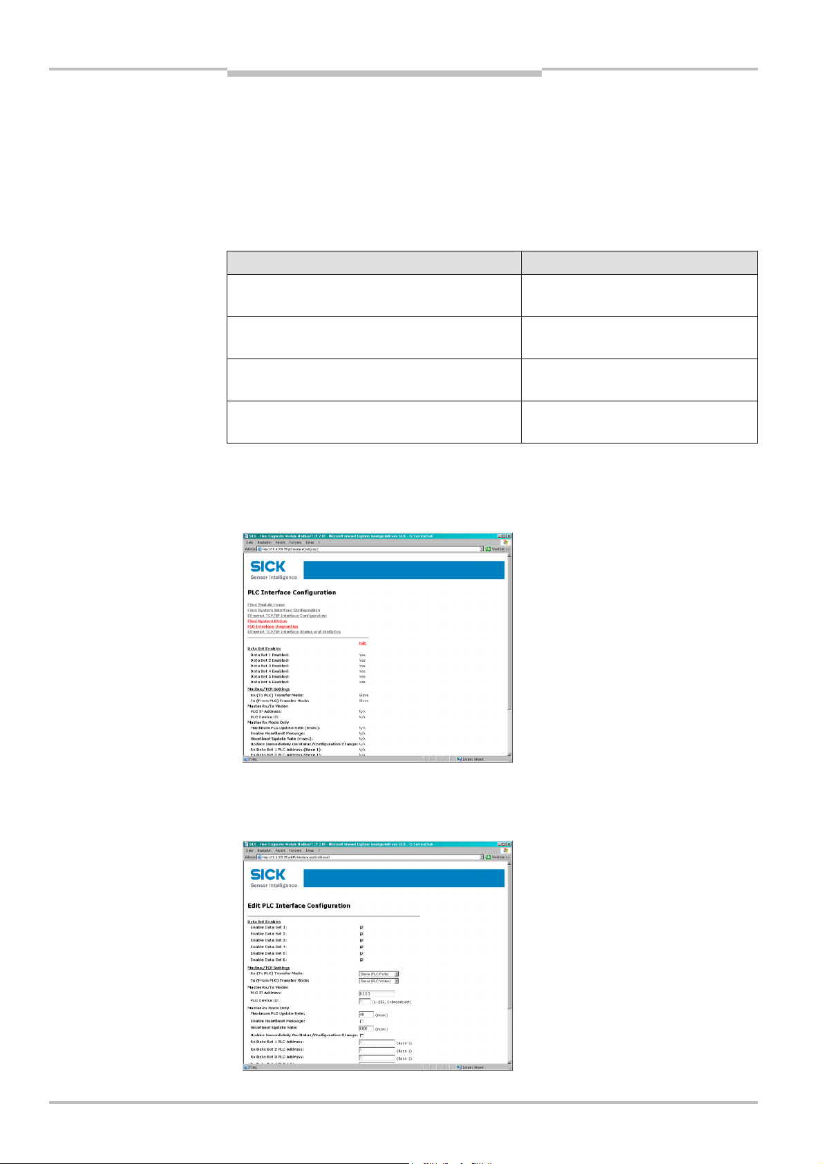
Chapter 7 Operating Instructions
Tab.61:
Number of possible
Modbus/TCP Ethernet Gateway
Flexi Classic Gateways
7.3 Configuration of the interface to the PLC — how the
data are transferred
The configuration steps in this section specify how the data on the higher-level PLC are
ransferred. Different operating modes can be selected to this purpose. The number of
t
possible connections to the PLC depends on whether the UE410-EN3 is operated as a
master or slave. Depending on the setting, up to 32 PLCs can address the UE410-EN3 at
the same time.
connections
Operating mode of the UE410-EN3 Maximum connections
Rx (To PLC) Transfer Mode: Master
Tx (From PLC) Transfer Mode: Master
Rx (To PLC) Transfer Mode: Master
Tx (From PLC) Transfer Mode: Slave
Rx (To PLC) Transfer Mode: Slave
Tx (From PLC) Transfer Mode: Master
Rx (To PLC) Transfer Mode: Slave
Tx (From PLC) Transfer Mode: Slave
Rx and Tx: 1
Rx: 1
Tx: 31
Rx: 31
Tx: 1
Rx and Tx: 32
Open a web browser on a PC in the network and go to the address of the UE410-EN3.
Click PLC Interface Configuration on the UE410-EN3 homepage. The following web
page is displayed:
54 © SICK AG • Industrial Safety Systems • Germany • All rights reserved 8011834/YT28/2016-03-15
The page shows the current settings of the interface to the PLC.
Click Edit to change the settings. The following web page is displayed:
Subject to change without notice
Page 55

Operating Instructions Chapter 7
Tab.62:
Data
sets 1
–
6 of
Tab.63:
Configuration of the
Flexi Classic Gateways
Modbus/TCP Ethernet Gateway
Decide which of the following 6 data sets are to be transferred to the PLC. For the exact
description of the data sets please refer to section 7.8.
UE410-EN3 in overview
interface to the PLC
Data set Description
1 Module-specific input data
2 Module-specific output data
3 Module-specific data of the UE410-EN3 gateway
4 General status and configuration data
5 Diagnostics data
6 Configuration data of the Flexi Classic system, user defined compilation
Select the desired data sets.
After the data sets have been selected, configure how they should be sent to the PLC.
For this purpose certain parameters that depend on the operating mode have to be set.
These are described below.
Overview of the selection and entry fields:
Selection/entry
window
Rx (To PLC)
Transfer Mode
Tx (From PLC)
Transfer Mode
Factory
setting
Slave (PLC
Polls)
Slave (PLC
Writes)
Description See
section
Determines the type of data transfer from UE410-
EN3 to the PLC.
Slave (PLC Polls) — PLC requests the data.
Master (Write to PLC) — UE410-EN3 writes the
data to the PLC memory.
Determines the type of data transfer from the PLC
to UE410-EN3.
Slave (PLC Writes) — PLC writes to the UE410-EN3
memory.
Master (Poll the PLC) — UE410-EN3 requests data
continuously from the PLC.
7.3.1
7.3.2
Settings for the operating modes Master RX and/or Master Tx
PLC IP Address 0.0.0.0 Specifies the PLC address in standard format xxx.xxx.xxx.xxx.
The selected data sets are transferred here.
PLC Device ID 1 Specifies the PLC device ID (typically 1).
Settings for the operating mode Master (Write to PLC):
Maximum PLC
Update Rate
Enable Heartbeat
Message
40 Defines the maximum rate (the minimum time interval) for
sending the data sets to the PLC. Settings occur dependent on
the PLC processing speed.
Minimum = 10 msec. Maximum = 65535 msec. The default
value of 40 msec. is suitable for most PLCs.
Note: If this value is greater than the Heartbeat Update Interval,
the Heartbeat Update Interval is increased (slowed down) to
this value.
Deactivated
Activates updating of the active data sets with the set Heart-
beat Update Rate.
Note: Either this option or Update Immediately on Status/Confi-
guration Change must be activated, otherwise no data will be
transferred!
8011834/YT28/2016-03-15 © SICK AG • Industrial Safety Systems • Germany • All rights reserved
Subject to change without notice
55
Page 56

Chapter 7 Operating Instructions
Modbus/TCP Ethernet Gateway
Flexi Classic Gateways
Selection/entry
window
Heartbeat Update
Interval
Update
Immediately on
Status/Configu-
ration Change
Rx Data Set N PLC
Address
Settings for the operating mode Master (Poll the PLC):
Factory
setting
5000 Specifies the Heartbeat Update Interval in milliseconds with
Deactivated Specifies whether the UE410-EN3 is to update the data in the
1 Specifies the start address of the PLC memory area to which
Description See
which the data are updated in the PLC.
Standard = 5000 msec., Minimum = 10 msec., Maximum =
65535 msec.
Note: If the Maximum PLC Update Rate is larger than the Heart-
beat Update Rate, the Heartbeat Update Rate is increased
(slowed down) to this value.
PLC immediately when changes occur in the data sets. If not
activated, the update is carried out with the next Heartbeat
Interval.
Note: Either this option or Enable Heartbeat Message must be
activated, otherwise no data will be transferred!
the data sets are to be sent. The start address is entered in
decimal form. The memory areas must be large enough to
accept the respective data sets. The memory areas are not
allowed to overlap. Data sets 1-5 have a fixed length, Data set
6 can have a variable length, depending on the setting (see
section 7.8).
section
Note
Digital Output
Polling Enable
Digital Output
Setting PLC
Address
Digital Output
Setting Polling
Rate
Deactivated Specifies whether the UE410-EN3 is to request the status of
the digital outputs from the PLC.
1 Specifies the PLC memory address from which the UE410-EN3
requests status of the digital outputs. The address is entered in
decimal form.
100 Specifies the interval in milliseconds in which the status of the
digital outputs is requested.
Minimum = 10 msec., Maximum = 65535 msec.
7.3.1 Operating modes in the transfer mode RX (To PLC)
Slave (PLC Polls) — PLC requests the data from UE410-EN3
In this operating mode the UE410-EN3 sends the data as slave upon request from the PLC.
If this operating mode is desired:
Chose the operating mode Slave (PLC Polls) in the RX (To PLC) Transfer Mode
selection field. All further settings do not apply.
Activate Save in Flash and click Submit to save the selection.
Only if Save in Flash is checked, will the new configuration be stored in the UE410-EN3’s
non-volatile memory and be available after a restart of the gateway. Submit without
checking Save in Flash allows, for example, the testing of new configurations without
overwriting the old configuration.
The following table lists the address to read out the data sets.
56 © SICK AG • Industrial Safety Systems • Germany • All rights reserved 8011834/YT28/2016-03-15
Subject to change without notice
Page 57

Operating Instructions Chapter 7
Tab.64:
Data addressing for
Flexi Classic Gateways
Modbus/TCP Ethernet Gateway
UE410-EN3 as receiver — data addressing:
UE410-EN3 as receiver
Note
Unit ID 1
Address
(Base 1)
1100 Request data set 1 Get 8
1180 Input data set 1 Set/Get 1
1200 Request data set 2 Get 8
1280 Input data set 2 Set/Get 1
1300 Request data set 3 Get 2
1380 Input data set 3 Set/Get 1
1400 Request data set 4 Get 3
1480 Input data set 4 Set/Get 1
1500 Request data set 5 Get 10
1580 Input data set 5 Set/Get 1
1600 Request data set 6 Get 2–62
1680 Input data set 6 Set/Get 1
Description Access Scope
(words)
The first word (two bytes) of the returned data of each data set is the current input number
which is incremented during each data update. The output value can be set by the PLC
and then tracked.
Note
Master (Write To PLC) — UE410-EN3 writes the data to the PLC memory
In this operating mode the UE410-EN3 as a master writes the data of all the activated
data sets in the specified memory areas of the PLC. If this operating mode is desired:
Chose the operating mode Master (Write to PLC) in the RX (To PLC) Transfer Mode
selection field.
Carry out the following settings on the same web page (see Tab. 63 on page 55):
– PLC IP Address
– PLC Device ID
– PLC update rate
– Enable Heartbeat Message (either this option or Update Immediately on
Status/Configuration Change must be activated!)
– Heartbeat Update Interval (if Heartbeat Message is activated)
– Update Immediately on Status/Configuration Change (either this option or Enable
Heartbeat Message must be activated!)
– Rx Data Set N PLC Address — for all activated data records
Activate Save in Flash and click Submit to save the selection.
Only if Save in Flash is checked, will the new configuration be stored in the UE410-EN3’s
non-volatile memory and be available after a restart of the gateway. Submit without
checking Save in Flash allows, for example, the testing of new configurations without
overwriting the old configuration.
8011834/YT28/2016-03-15 © SICK AG • Industrial Safety Systems • Germany • All rights reserved
Subject to change without notice
57
Page 58

Chapter 7 Operating Instructions
Tab.65:
Data addressing of
Tab.66:
Modbus commands
Modbus/TCP Ethernet Gateway
Flexi Classic Gateways
7.3.2 Operating modes in the transfer mode Tx (From PLC)
Slave (PLC writes) — PLC sends digital output data to the UE410-EN3
In this operating mode the PLC sends writing requirements as master to the UE410-EN3 in
order to set the digital outputs. If this operating mode is desired:
Chose the operating mode Slave (PLC Writes) in the Tx (From PLC) Transfer Mode
selection field. All the further settings do not apply.
Activate Save in Flash and click Submit to save the selection.
Note
Only if Save in Flash is checked, will the new configuration be stored in the UE410-EN3’s
non-volatile memory and be available after a restart of the gateway. Submit without
checking Save in Flash allows, for example, the testing of new configurations without
overwriting the old configuration.
UE410-EN3 as slave — addressing the digital outputs:
the UE410-EN3 digital
outputs
Note
Unit ID 1
Address
(Base 1)
1800 Digital outputs Set/Get 1
Description Access Scope
(words)
Master (Poll the PLC) — UE410-EN3 requests the data from the PLC.
In this operating mode the UE410-EN3 as master requests the data continuously from the
PLC in order to set the digital output settings. If this operating mode is desired:
Select the operating mode Master (Poll the PLC) in the Tx (From PLC) Transfer Mode
selection field.
Carry out the following settings on the same web page (see Tab. 63 on page 55):
– PLC IP Address
– PLC Device ID
– Digital Output Polling Enable
– Digital Output Setting PLC Address
– Digital Output Setting Polling Rate
Activate Save in Flash and click Submit to save the selection.
Only if Save in Flash is checked, will the new configuration be stored in the UE410-EN3’s
non-volatile memory and be available after a restart of the gateway. Submit without
checking Save in Flash allows, for example, the testing of new configurations without
overwriting the old configuration.
58 © SICK AG • Industrial Safety Systems • Germany • All rights reserved 8011834/YT28/2016-03-15
7.3.3 Modbus commands and error messages
The UE410-EN3 supports the following Modbus commands and error messages:
Modbus command Value
Read Holding Registers 3
Write Multiple Registers 16 (10hex)
Read/Write Multiple Registers 23 (17hex)
Subject to change without notice
Page 59

Operating Instructions Chapter 7
Tab.67:
Modbus error
Flexi Classic Gateways
Modbus/TCP Ethernet Gateway
messages
Modbus error response Description
1 Illegal Function The requested function is not supported.
2 Illegal Data Address Undefined data address received.
3 Illegal Data Value Request with illegal data values, for example not enough data
requested for a data set.
10 Gateway Paths Not Available Invalid configuration, for example polling or setting of the digital
outputs via PLC during operation of the UE410-EN3 in master
mode.
7.4 Configuration of the gateway — which data are
transferred
The UE410-EN3 processes the data of a UE410-EN3 Flexi Classic system and makes them
available in different compilations, the data sets for the PLC.
The configuration steps in this section are used to define which data sets are transferred
to the higher-level PLC. There are 6 data sets available to this purpose: Data sets 1-5
contain fixed data compilations, Data set 6 can be configured by the user. The data sets
that are to be transferred to the PLC must be activated.
Open a web browser on a PC in the network and go to the address of the UE410-EN3.
Click Flexi System Interface Configuration on the UE410-EN3 homepage. The
following web page is displayed:
8011834/YT28/2016-03-15 © SICK AG • Industrial Safety Systems • Germany • All rights reserved
Subject to change without notice
59
Page 60

Chapter 7 Operating Instructions
Note
Modbus/TCP Ethernet Gateway
Flexi Classic Gateways
The installed Flexi Classic modules are recognised automatically and listed in the Flexi
Chassis Configuration field. Modules of the next Flexi Classic generation that are not yet
recognised by the UE410-EN3 are listed as “Unknown Module”. The corresponding front
and the data structure of the module can be displayed by clicking a module. In the
example, a click on Module 1 displays a new window with the corresponding information.
The window can subsequently be closed again.
After resetting the UE410-EN3 back to the factory settings, all modules are displayed as
“Unknown Module” until a hardware reset of the entire Flexi Classic system has been
carried out (see section 7.6).
In order to use Data set 6, click Set 6. The following web page is displayed and shows
the current compilation of Data set 6:
Click Configure Set 6, to compile the user defined data record. The following web page
is displayed:
60 © SICK AG • Industrial Safety Systems • Germany • All rights reserved 8011834/YT28/2016-03-15
Subject to change without notice
Page 61

Operating Instructions Chapter 7
Flexi Classic Gateways
Note
Modbus/TCP Ethernet Gateway
Select the desired data. For the exact description of the data sets please refer to
section 7.8.
n the standard setting, all parameters are sent to the higher level PLC when Data set 6 is
I
active. If only specific parameters are to be sent:
Select Return Only Enabled Data and click the desired parameters in the list.
If Return Only Enabled Data is activated, the length of Data set 6 is variable. This must
be taken into account when addressing the memory area in the PLC.
In order to use these settings temporarily do not check Save in Flash and click Submit.
In order to use these settings permanently, check Save in Flash and click Submit. The
configuration is then saved in the non-volatile memory of the UE410-EN3 and is still
available after the gateway has been restarted.
The current configuration of Data set 6 can be displayed by clicking Display Set 6 Data
Format. The following web page is displayed:
Return to the previous page by using the browser’s Back button.
7.5 Status of the interface to the PLC
The UE410-EN3 has its own page that makes statistical data and diagnostics data of the
interface available to the PLC. On this page all the messages and responses from the PLC
and UE410-EN3 are counted and errors including error messages for diagnostic purposes
are displayed. The page is updated automatically every 10 seconds.
Click PLC Interface Diagnostics. The following web page is displayed:
8011834/YT28/2016-03-15 © SICK AG • Industrial Safety Systems • Germany • All rights reserved
Subject to change without notice
61
Page 62

Chapter 7 Operating Instructions
Tab.68:
Statistical data and
Modbus/TCP Ethernet Gateway
Flexi Classic Gateways
diagnostic data of the
interface to the PLC
Entry Description
Slave mode specific statistics
Messages Received From
PLC
Responses Sent to PLC Specifies the number of responses to the PLC.
Invalid Command Lengths Specifies the number of received messages with invalid command
Invalid Message Data
Errors
Unknown Request
Destination IDs
Invalid Request Protocol
Types
Unsupported Modbus
Function Codes
Master mode specific statistics
Messages Sent To PLC Specifies the number of messages that were sent to the PLC.
Specifies the number of messages that were received from the PLC.
lengths.
Specifies the number of received messages that led to an Invalid
Message Data Error. This error occurs when a message with invalid
data is received.
Specifies the number of received messages with unknown
destination IDs (Request Destination IDs).
Specifies the number of received messages that led to an Invalid
Protocol Error. This error occurs when a message does not contain
the value zero for the Modbus protocol.
Specifies the number of received messages with an unsupported
function code.
Responses Received From
PLC
Invalid Response Data
Errors
Error responses Specifies the number of responses from the PLC that contain error
Unexpected Response
Function Codes
Unknown Response
Destination IDs
Invalid Response Protocol
Types
Failed Modbus/TCP
Connection Attempts
Specifies the number of responses from the PLC.
Specifies the number of faulty response data that were sent to the
PLC upon request. Possible reasons include:
No data returned upon request of the digital output settings
messages. Possible reasons include:
Invalid configuration of the PLC address
Incorrect configuration of the PLC
Specifies the number of Unexpected Response Function Codes that
were received in a message in master receive mode or master send
mode. This error occurs when a message without the expected
function code is received.
Specifies the number of received messages with unknown destina-
tion IDs (Request Destination IDs). This error occurs when the PLC
responds to a message with an unknown destination ID.
Specifies the number of received messages that led to an Invalid
Protocol Error. This error occurs when a response does not contain
the value zero for the Modbus protocol.
Specifies the number of failed attempts to reach the specified PLC
address via the Modbus/TCP connection.
62 © SICK AG • Industrial Safety Systems • Germany • All rights reserved 8011834/YT28/2016-03-15
Subject to change without notice
Page 63

Operating Instructions Chapter 7
Flexi Classic Gateways
Modbus/TCP Ethernet Gateway
Entry Description
Modbus/TCP Connection
Problems
Specifies the number of problems that occurred during attempted
Modbus/TCP connections. This error occurs when the unit responds
and the connection is established but the connection options cannot
be configured. Possible reasons include:
TCP connection set to TCP_NODELAY
Socket connection set to SO_OOBINLINE
Socket connection set to SO_KEEPALIVE.
No Available Modbus/TCP
Connection Errors
Non-mode specific statistics/diagnostics
Improper Configuration
Errors
System Resource Errors Specifies the number of System Resource Errors. This error occurs
First Error Description Specifies the error message for the first determined error.
Last Error Description Specifies the error message for the last determined error.
Specifies the number of aborted connections due to unavailable
Modbus/TCP connections. This error occurs when the maximum
number of Modbus/TCP connections has been reached and the
UE410-EN3 tries to establish a further Modbus/TCP connection.
Specifies the number of determined configuration faults.
when, for example, writing to the flash memory fails.
8011834/YT28/2016-03-15 © SICK AG • Industrial Safety Systems • Germany • All rights reserved
Subject to change without notice
63
Page 64

Chapter 7 Operating Instructions
Modbus/TCP Ethernet Gateway
Flexi Classic Gateways
7.6 Resetting to factory settings
he UE410-EN can be reset to the factory settings as follows:
T
Open a web browser on a PC in the same network and go to the address of the
UE410FEN. The following web page is displayed:
Click the reboot button. The following web page is displayed:
Activate Set configuration for PLC Interface and Data Sets to factory default settings.
Click the button Yes: Reboot. The following web page is displayed:
The UE410-EN is reset to the factory settings. The web server of the UE410-EN is called up
again automatically.
64 © SICK AG • Industrial Safety Systems • Germany • All rights reserved 8011834/YT28/2016-03-15
Subject to change without notice
Page 65

Operating Instructions Chapter 7
Tab.69:
Troubleshooting
Flexi Classic Gateways
Modbus/TCP Ethernet Gateway
Notes
The only exception is the UE410-EN IP address, which is not reset to factory settings
with this action.
After resetting to factory settings, the UE410-EN does not identify the connected Flexi
Classic module again, but displays all modules as “Unknown Modules”. In addition the
UE410-EN loses the system information MOD-ID, CRC1, CRC2, SWVERSION_H, SWVERSION_L, FUNCTION, KONF, CRC_H CODE and CRC_L CODE and transfers zeros into
the corresponding data sets. Restarting the Flexi Classic system remedies this problem.
Interrupt the power supply of the Flexi Classic system and switch on again.
7.7 Troubleshooting
Error Cause Remedy
The browser does not find
the UE410-EN homepage
during configuration.
UE410-EN has no power
supply.
UE410-EN is not in the same
physical network as the PC.
The PC is configured to another
subnet mask in the TCP/IP
settings.
UE410-EN has already been
configured once and has a
fixed set IP address or an IP
address assigned by a DHCP
server that is not recognised.
Establish the power supply.
Check the Ethernet wiring and
network settings on the PC and
correct if necessary.
Set the subnet mask on the PC to
255.255.0.0 (factory setting of the
UE410FEN).
The software tool Flexi Classic
IPFLink can be used to scan the
network for connected Flexi Classic
modules and to determine the
network address.
UE410-EN does not supply
any data.
LED PWR Green
LED LINK/ACT / Green
LED ERR Green
UE410-EN does not supply
any data.
LED PWR Green
LED LINK/ACT / Green
LED ERR Green
UE410-EN functioned
correctly after configura-
tion, but suddenly no longer
supplies data.
LED PWR Green
LED LINK/ACT / Green
LED ERR Green
UE410-EN is configured to the
operating mode Master (Write
to PLC), but neither Heartbeat
nor Update Immediately on
Status/Configuration Change
are activated.
No data set is activated. Activate at least one data set.
UE410-EN is operated in slave
mode, the IP address is as-
signed from a DHCP server.
After the UE410-EN or the
DHCP server has been restar-
ted, a different IP address that
is unknown to the PLC has
been assigned to the
UE410FEN.
Activate one of the named
functions.
Either assign a fixed IP address to
the UE410FEN, or reserve a fixed IP
address for the UE410FEN in the
DHCP server (manual assignment
by means of the MAC address of
the UE410-EN).
8011834/YT28/2016-03-15 © SICK AG • Industrial Safety Systems • Germany • All rights reserved
Subject to change without notice
65
Page 66

Chapter 7 Operating Instructions
Modbus/TCP Ethernet Gateway
Error Cause Remedy
UE410-EN does not have a
connection to the Flexi
Classic system.
LED PWR Green
LED LINK/ACT / Green
LED ERR Red
UE410-EN is not plugged
properly into the other Flexi
Classic module.
Module connecting plug is
soiled or damaged.
Plug the UE410-EN in correctly,
clean the connecting socket/plug.
Flexi Classic Gateways
UE410-EN does not supply
any data and cannot be
accessed via the web
browser.
LED PWR Green
LED LINK/ACT / Green
LED ERR Red
UE410-EN transfers only
zeros for the system
information MOD-ID, CRC1,
CRC2, SWVERSION_H, SW-
VERSION_L, FUNCTION,
KONF, CRC_H CODE and
CRC_L CODE; all connected
Flexi Classic modules are
only listed as “Unknown
Modules” on the
configuration pages.
Internal device error Switch off the power supply of the
Flexi Classic system and switch it
on again. If the error remains,
replace the gateway.
UE410-EN was reset to the
factory settings, but no hard-
ware reset of the Flexi Classic
systems was carried out.
Switch off the power supply of the
Flexi Classic system and switch on
again.
Symbol description:
LED offGreen: LED lights up green Red: LED flashes red
66 © SICK AG • Industrial Safety Systems • Germany • All rights reserved 8011834/YT28/2016-03-15
Subject to change without notice
Page 67

Operating Instructions Chapter 7
Tab.70:
Data sets 1
–
5 of the
Flexi Classic Gateways
Modbus/TCP Ethernet Gateway
7.8 Description of the data sets
7.8.1 Data sets 1-5
The compilation of data sets 1-5 is fixed; these data sets can only be activated or deactivated as a whole. The length of these data sets is always the same. The data will be zeroed
for modules that do not exist.
UE410-EN
Data set 1 Data set 2 Data set 3 Data set 4 Data set 5
Input data Output data Gateway-
specific
diagnostic
data
Byte 1 MED1 MQD1 DIG_OUT1 BAS1 MFD1
Byte 2 MED2 MQD2 DIG_OUT2 Backplane
Byte 3 MED3 MQD3 – CRC1 MFD3
Byte 4 MED4 MQD4 – CRC2 MFD4
Byte 5 MED5 MQD5 – – MFD5
Byte 6 MED6 MQD6 – – MFD6
Byte 7 MED7 MQD7 – – MFD7
Byte 8 MED8 MQD8 – – MFD8
Byte 9 MED9 MQD9 – – MFD9
Byte 10 MED10 MQD10 – – MFD10
Byte 11 MED11 MQD11 – – MFD11
Byte 12 MED12 MQD12 – – MFD12
Byte 13 MED13 MQD13 – – MFD13
General
diagnostic
data
Fault
Module-specific
diagnostic data
MFD2
Byte 14 0* 0* – – 0*
Byte 15-18 – – – – MFCLASS1/ CODE1,
MFCLASS2/CODE2 (1)
Byte 19-22 – – – – MFCLASS1/ CODE1,
MFCLASS2/CODE2 (2)
Byte 23-26 – – – – MFCLASS1/ CODE1,
MFCLASS2/CODE2 (3)
Byte 27-30 – – – – MFCLASS1/ CODE1,
MFCLASS2/CODE2 (4)
Byte 31-34 – – – – MFCLASS1/ CODE1,
MFCLASS2/CODE2 (5)
Byte 35-38 – – – – MFCLASS1/ CODE1,
MFCLASS2/CODE2 (6)
Byte 39-42 – – – – MFCLASS1/ CODE1,
MFCLASS2/CODE2 (7)
Byte 43-46 – – – – MFCLASS1/ CODE1,
MFCLASS2/CODE2 (8)
8011834/YT28/2016-03-15 © SICK AG • Industrial Safety Systems • Germany • All rights reserved
Subject to change without notice
67
Page 68

Chapter 7 Operating Instructions
Modbus/TCP Ethernet Gateway
Flexi Classic Gateways
Data set 1 Data set 2 Data set 3 Data set 4 Data set 5
Input data Output data Gateway-
specific
diagnostic
data
Byte 47-50 – – – – MFCLASS1/ CODE1,
Byte 51-54 – – – – MFCLASS1/ CODE1,
Byte 55-58 – – – – MFCLASS1/ CODE1,
Byte 59-62 – – – – MFCLASS1/ CODE1,
Byte 63-66 – – – – MFCLASS1/ CODE1,
Length 14 Bytes 14 Bytes 2 Bytes 4 Bytes 66 Bytes
General
diagnostic
data
Module-specific
diagnostic data
MFCLASS2/CODE2 (9)
MFCLASS2/CODE2 (10)
MFCLASS2/CODE2 (11)
MFCLASS2/CODE2 (12)
MFCLASS2/CODE2 (13)
* Inserted for byte alignment
68 © SICK AG • Industrial Safety Systems • Germany • All rights reserved 8011834/YT28/2016-03-15
Subject to change without notice
Page 69

Operating Instructions Chapter 7
Tab.71:
Data set 6 of the
Flexi Classic Gateways
Modbus/TCP Ethernet Gateway
7.8.2 Data set 6, can be compiled by the user
The contents of Data set 6 can be compiled by the user.
If the option Return only enabled Data is activated in the configuration of the data set
(see section “Configuration …” above), the data set can have a different length depending
on the compilation. The maximum length is 124 bytes. The minimum length is 2 bytes.
The selected data are transferred for all Flexi Classic modules respectively.
The data are zeroed for modules that do not exist.
Note
If data is expected in 16-bit words and in the format Big Endian (e.g. Modbus/TCP), it is
transferred with the more significant byte first.
UE410-EN
Byte
1-124
Data set 6
CRC-H CRC-L
MKD1.1 MKD2.1 MKD1.2 MKD2.2 MKD1.3 MKD2.3
MKD1.4 MKD2.4 MKD1.5 MKD2.5 MKD1.6 MKD2.6
MKD1.7 MKD2.7 MKD1.8 MKD2.8 MKD1.9 MKD2.9
MKD1.10 MKD2.10 MKD1.11 MKD2.11 MKD1.12 MKD2.12
MKD1.13 MKD2.13
MOD-ID1 MOD-ID2 MOD-ID3 MOD-ID4 MOD-ID5 MOD-ID6
MOD-ID7 MOD-ID8 MOD-ID9 MOD-ID10 MOD-ID11 MOD-D12
MOD-13 0
SW Version
Byte 1,
Module 1
SW Version
Byte 1,
Module 4
SW Version
Byte 1,
Module 7
SW Version
Byte 2,
Module 1
SW Version
Byte 2,
Module 4
SW Version
Byte 2,
Module 7
SW Version
Byte 1,
Module 2
SW Version
Byte 1,
Module 5
SW Version
Byte 1,
Module 8
SW Version
Byte 2,
Module 2
SW Version
Byte 2,
Module 5
SW Version
Byte 2,
Module 8
SW Version
Byte 1,
Module 3
SW Version
Byte 1,
Module 6
SW Version
Byte 1,
Module 9
SW Version
Byte 2,
Module 3
SW Version
Byte 2,
Module 6
SW Version
Byte 2,
Module 9
SW Version
Byte 1,
Module 10
SW Version
Byte 1,
Module 13
Function 1 Function 2 Function 3 Function 4 Function 5 Function 6
Function 7 Function 8 Function 9 Function 10 Function 11 Function 12
Function 13 0
8011834/YT28/2016-03-15 © SICK AG • Industrial Safety Systems • Germany • All rights reserved
Subject to change without notice
SW Version
Byte 2,
Module 10
SW Version
Byte 2,
Module 13
SW Version
Byte 1,
Module 11
SW Version
Byte 2,
Module 11
SW Version
Byte 1,
Module 12
SW Version
Byte 2,
Module 12
69
Page 70

Chapter 7 Operating Instructions
Modbus/TCP Ethernet Gateway
Data set 6
Conf 1 Conf 2 Conf 3 Conf 4 Conf 5 Conf 6
Conf 7 Conf 8 Conf 9 Conf 10 Conf 11 Conf 12
Conf 13 0
CRC
Byte 1,
Module 1
CRC
Byte 2,
Module 1
CRC
Byte 1,
Module 2
CRC
Byte 2,
Module 2
Flexi Classic Gateways
CRC
Byte 1,
Module 3
CRC
Byte 2,
Module 3
CRC
Byte 1,
Module 4
CRC
Byte 1,
Module 7
CRC
Byte 1,
Module 10
CRC
Byte 1,
Module 13
DIAG
Version
Byte 1
CRC
Byte 2,
Module 4
CRC
Byte 2,
Module 7
CRC
Byte 2,
Module 10
CRC
Byte 2,
Module 13
DIAG
Version
Byte 2
CRC
Byte 1,
Module 5
CRC
Byte 1,
Module 8
CRC
Byte 1,
Module 11
CRC
Byte 2,
Module 5
CRC
Byte 2,
Module 8
CRC
Byte 2,
Module 11
CRC
Byte 1,
Module 6
CRC
Byte 1,
Module 9
CRC
Byte 1,
Module 12
CRC
Byte 2,
Module 6
CRC
Byte 2,
Module 9
CRC
Byte 2,
Module 12
70 © SICK AG • Industrial Safety Systems • Germany • All rights reserved 8011834/YT28/2016-03-15
Subject to change without notice
Page 71
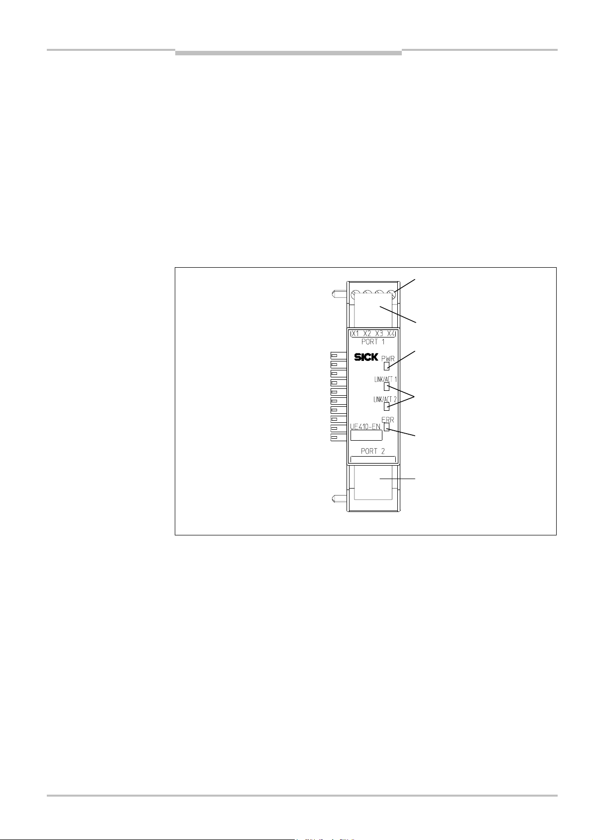
Operating Instructions Chapter 8
Fig.18:
Interfaces and
Terminals of
digital control
RJ45 Ethernet socket
RJ45 Ethernet socket
LED power supply (green)
LED network activity for
LED Error (red/green)
Flexi Classic Gateways
Ethernet TCP/IP Gateway
8 Ethernet TCP/IP Gateway
he following Flexi Classic gateways can be used for Ethernet TCP/IP:
T
UE410-EN3
UE410-EN1
8.1 Interfaces and operation
The UE410-EN is equipped with four digital control outputs X1–X4.
The UE410-EN is equipped with an integrated 3-port switch for connection with the Ethernet network. Two RJ45 sockets are available for the connection. The switch functionality
allows the UE410-EN to be used for connection to another Ethernet component (e.g. connection to a notebook) without having to interrupt the Ethernet connection to the network.
display elements of the
UE410-EN
outputs X1–X4
Ethernet port 1 or 2 (green)
8011834/YT28/2016-03-15 © SICK AG • Industrial Safety Systems • Germany • All rights reserved
Subject to change without notice
71
Page 72
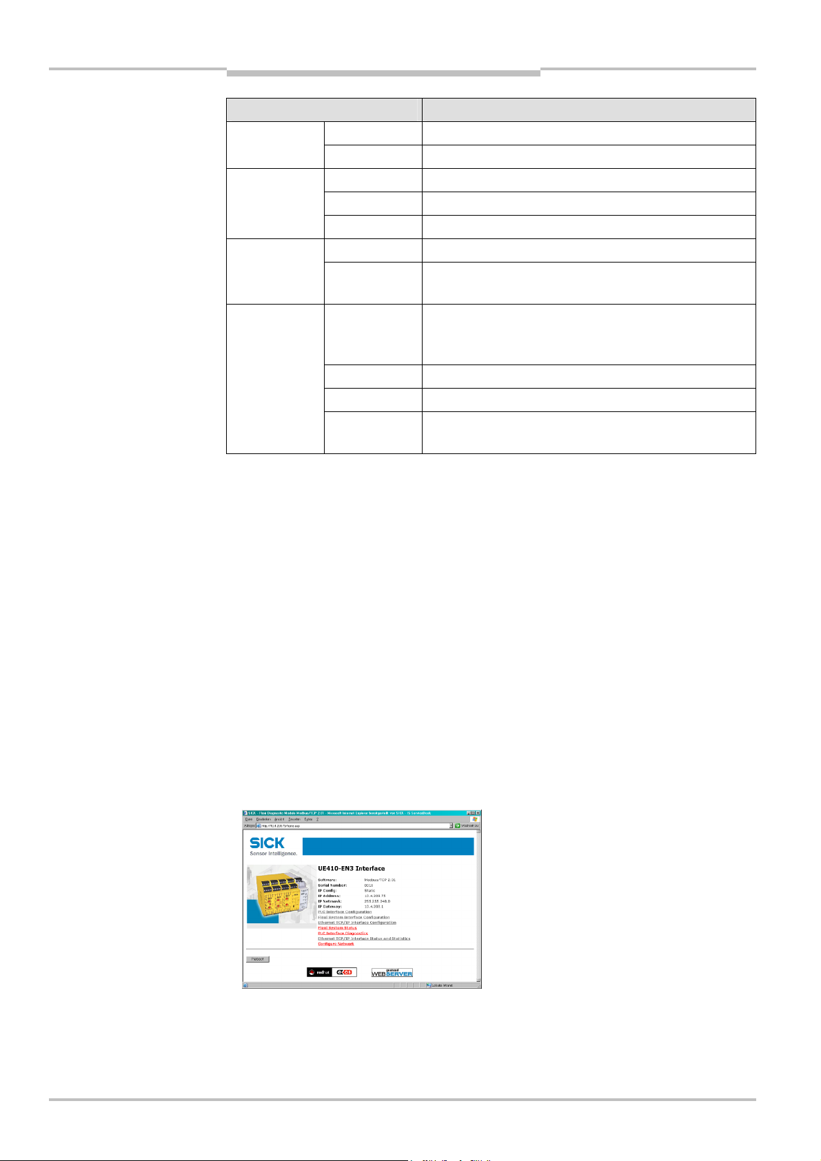
Chapter 8 Operating Instructions
Tab.72:
Meaning of the LED
Ethernet TCP/IP Gateway
Flexi Classic Gateways
displays
Note
LED Meaning
No power supply PWR
Green Power supply switched on
LINK/ACT 1
LINK/ACT 2
No Ethernet connection
Green Ethernet connection active, no data transmission
Green Ethernet connection active, data transmission
No power supply ERR
Green Gateway operating, no error message, at least one
Ethernet connection exists
Green Gateway operating, valid IP address assigned, configu-
ration is valid, but no Ethernet connection established.
All data sets are deactivated
Red No flex bus communication
Red Internal device error
Red/Green Self-test of the gateway after switching on the power
supply on the Flexi Classic system
Symbol description:
LED off Green: LED lights up green Red: LED flashes red
Error elimination is described in section “Troubleshooting” below.
8.2 Basic configuration — assigning an IP address
Configuration of the UE410-EN is performed browser-supported via the integrated web
server of the gateway.
Ensure that the UE410-EN is installed correctly, energised and connected with the
Ethernet network.
Open a web browser on a PC in the same network and go to the address of the
UE410FEN. Upon delivery, the UE410-EN is configured for the following address:
– IP address 192.168.250.250
– Subnet mask 255.255.0.0
– Default gateway 0.0.0.0
The following web page is displayed:
72 © SICK AG • Industrial Safety Systems • Germany • All rights reserved 8011834/YT28/2016-03-15
Subject to change without notice
Page 73

Operating Instructions Chapter 8
Flexi Classic Gateways
Ethernet TCP/IP Gateway
To assign a suitable IP address within the network to the UE410-EN, click Configure
Network. The following web page is displayed:
The UE410-EN network address can be obtained automatically or configured manually.
For automatic assignment of the network address, choose Use DHCP.
Note
A DHCP server must be active in the network so that these functions can be used. A new IP
address will be assigned to the UE410-EN when the DHCP server or the UE410-EN is
restarted. When the UE410-EN is operated in slave mode (see section “Configuration …”
below) and the IP address changes due to a restart, the PLC can no longer communicate
with the UE410-EN. If you use the Use DHCP function in combination with the slave mode
of the UE410-EN, we recommend that you reserve a specific IP address for the UE410-EN
(manual assignment on the basis of the MAC address of the UE410-EN).
In order to set the network address manually, choose Use static configuration below
and enter a valid free IP address, the subnet mask and the IP address of the network
gateway.
Finalise changes by clicking Save.
The new network address is saved in the UE410-EN flash memory, but will only become
effective after the gateway has been restarted. In order to restart the gateway, …
either click the Reboot button on the homepage of the UE410-EN main page
or interrupt the power supply of the Flexi Classic system and switch on again.
Call up the new address of the UE410-EN in order to configure the UE410-EN in the web
browser further.
Note
If a DHCP server is used to assign an IP address, the new address is unknown to the
system administrator. It can be read out in the administration pages of the DHCP server.
Alternatively the software tool Flexi Classic IP-Link can be used. This scans the network for
Flexi Classic modules and registers their IP addresses.
8011834/YT28/2016-03-15 © SICK AG • Industrial Safety Systems • Germany • All rights reserved
Subject to change without notice
73
Page 74

Chapter 8 Operating Instructions
Ethernet TCP/IP Gateway
Flexi Classic Gateways
8.3 Configuration of the TCP/IP interface — who
establishes the connection
The UE410-EN supports a total number of four TCP/IP socket interfaces. This allows up to
our different applications to communicate with the UE410-EN at the same time over
f
Ethernet TCP/IP. Other UE410-EN network interfaces (e.g. Modbus/TCP or EtherNet/IP)
run in parallel and their configuration or usage does not interact with the TCP/IP socket
configuration as well as it happens independently on separate web pages.
The UE410-EN processes the data of a Flexi Classic system and makes it available in different compilations, the data sets. These data sets are available over the TCP/IP interface.
For a detailed description of the data sets please refer to section “Description of the data
sets” below.
Note
Through the TCP/IP socket interface data set 6 will always be returned with the maximum
length of 124 bytes even though it may have been compiled to be less for the Modbus/TCP interface.
Open a web browser on a PC in the network and go to the address of the UE410-EN.
Click Ethernet TCP/IP Interface Configuration on the UE410-EN homepage. The
following web page is displayed:
The page shows the current settings of the Ethernet TCP/IP Interface.
The default configuration for each socket interface allows an application running on
another computer to connect to the UE410-EN module and send request messages. No
automatic updates are configured in the default configuration (Polling Mode).
If the default configuration is acceptable for the user application, then the application
can connect to any of the socket interfaces and begin sending command messages and
receiving responses.
To change the Listen Port, have the UE410-EN module connect to your application, or
enable the Auto Update Mode for any or all data sets, please follow the configuration
steps below.
74 © SICK AG • Industrial Safety Systems • Germany • All rights reserved 8011834/YT28/2016-03-15
Subject to change without notice
Page 75

Operating Instructions Chapter 8
Flexi Classic Gateways
Ethernet TCP/IP Gateway
Click Socket N to edit any of the four socket interfaces. The following web page is
displayed:
Note
Enter the Listen Port number that is more appropriate to the user application.
Port 9000 and port 9001 are reserved and shall not be configured.
Set Connect To Mode to Never if the application shall connect to the UE410-EN.
Activate Save in Flash and click Submit to save the selection or continue configuration.
When a reserved port has been entered as Listen Port, a special web page will be displayed upon Submit. The following page will be displayed:
Select Use default Listen Port of N to reset the Listen Port configuration to the valid
default port number of the socket. If this checkbox remains unchecked, the invalid port
number will remain entered when returning back to the configuration page and shall
still be changed to another value.
Click Submit to return to the Edit Socket N Configuration web page.
8011834/YT28/2016-03-15 © SICK AG • Industrial Safety Systems • Germany • All rights reserved
Subject to change without notice
75
Page 76

Chapter 8 Operating Instructions
Ethernet TCP/IP Gateway
Flexi Classic Gateways
Once the UE410-EN shall connect to the application, perform the following configuration
steps:
Uncheck the Listen checkbox.
Set the Connect To Mode to Connect Always.
Enter the port number of the application for Connect Port
Set Connect IP Address to the IP Address of the computer the application is running on.
Activate Save in Flash and click Submit to save the selection or continue configuration.
Select Reset Port and click Submit if you would like to completely reset the socket port
configuration. This will force any active TCP/IP connections to close and clear all statistics.
8.4 Data transfer method — how the data are transferred
Whenever the TCP/IP socket connection has been established (either by an application on
a PC or by the UE410-EN itself), there are two possible ways how the data sets can be
transferred:
The application requests the data set(s) per command message (Polling Mode) or
the UE410-EN auto-updates the data sets as per configuration (Auto Update Mode).
For both methods the following structure of messages applies.
8.4.1 General telegram structure
The request/response message (e.g. telegram) is structured as shown below:
WORD
0 1 … … … … … … … … … … … … … n
Command
Parameter(s)
(content depends on type of command)
Seq.
num.
Data
76 © SICK AG • Industrial Safety Systems • Germany • All rights reserved 8011834/YT28/2016-03-15
Subject to change without notice
Page 77

Operating Instructions Chapter 8
Tab.73: Telegram structure
Tab.74:
Error response
Flexi Classic Gateways
Ethernet TCP/IP Gateway
Parameter Length Description
Command WORD 0hex = Undefined (no command)
Polling mode specific
00F1hex = Data set(s) request message
001Fhex = Data set(s) response message
Auto-update specific
00E1hex = Auto-Update Control
001Ehex = Auto-Update Control Response
002Ehex = Auto-Update Data set(s) message
Digital outputs read/write
00F2hex = Write Digital Output settings
002Fhex = Response to write Digital Output settings
00F3hex = Request Current Digital Output settings
003Fhex = Read Digital Output settings response
Parameter(s) (Length de-
termined by
command)
As defined in specific command
message
Sequential
Number
Data (Length de-
WORD Sequential number to be incremented with each new message.
As defined in specific command
termined by
command)
8.4.2 Error response to invalid messages
The UE410-EN will set the most significant bit of the command word in the event that an
invalid or improperly formatted message is received.
Parameter Length Description
Command WORD Bit 15 of received command will be set.
(i.e. Command of 00F2hex would become 80F2hex.)
Following data (Length de-
termined by
command)
Unchanged. Returned as it was received.
8.4.3 Auto Update Mode
The UE410-EN can be configured to automatically update the data set information (e.g.
the application does not need to send any request messages as it would do in polling
mode, see section 8.4.4 for details) once the connection to the application has been made.
The configuration settings are available via the UE410-EN Web Server or via the TCP/IP
interface itself. Using one interface does not disable the other: The Auto Update Mode
could be enabled via web server and disabled via TCP/IP command, for example.
8011834/YT28/2016-03-15 © SICK AG • Industrial Safety Systems • Germany • All rights reserved
Subject to change without notice
77
Page 78

Chapter 8 Operating Instructions
Note
Ethernet TCP/IP Gateway
Flexi Classic Gateways
Configuration via web server
In order to configure the Auto Update Mode via web server, perform the following configu-
ation steps:
r
Open a web browser on a PC in the network and go to the address of the UE410-EN.
Click Ethernet TCP/IP Interface Configuration on the UE410-EN homepage.
Click Socket N to edit any of the four socket interfaces.
Select the data sets which shall be included in the TCP/IP message by checking the
respective Checkbox Enable Data Set N.
These data sets will be sent to the application whenever a change is detected and, if
Enable Heartbeat Message is enabled, at least as often as the specified Heartbeat
Update Rate.
Select Enable Heartbeat Message if the selected data set(s) shall be constantly sent
on a specified rate (whether the content has changed or not).
Set the Heartbeat Update Rate to the required value.
The Heartbeat Update Rate specifies the update interval in milliseconds with which the
data sets are updated to the application. Standard = 5000 ms, Minimum = 200 ms,
Maximum = 65535 ms. Any value entered less than 200 ms will be increased to
200 ms.
Activate Save in Flash and click Submit to save the selection or continue configuration.
If Heartbeat Message has been enabled but no data set is selected (e.g. none of the
Checkboxes Enable Data Set N is checked), the UE410-EN will not send any Auto Update
TCP/IP messages and remain in Polling Mode.
78 © SICK AG • Industrial Safety Systems • Germany • All rights reserved 8011834/YT28/2016-03-15
Subject to change without notice
Page 79

Operating Instructions Chapter 8
Tab.75:
Auto Update Mode
Tab.76:
Auto Update Mode
Flexi Classic Gateways
Ethernet TCP/IP Gateway
Configuration via TCP/IP interface
This command message is sent by an application to the UE410-EN to configure the Auto
pdate Mode. This message can be used to either disable or enable the Auto Update
U
Mode directly through the TCP/IP interface.
configuration command
Parameter Length Value
Command WORD 00E1Hex = Auto-Update Control
Request Data
Set 1
Request Data
Set 2
Request Data
Set 3
Request Data
Set 4
Request Data
Set 5
Request Data
Set 6
Sequential
Number
Heartbeat Mode
Update Rate
WORD 0 = Do not send Data Set 1
1 = Send Data Set 1
WORD 0 = Do not send Data Set 2
1 = Send Data Set 2
WORD 0 = Do not send Data Set 3
1 = Send Data Set 3
WORD 0 = Do not send Data Set 4
1 = Send Data Set 4
WORD 0 = Do not send Data Set 5
1 = Send Data Set 5
WORD 0 = Do not send Data Set 6
1 = Send Data Set 6
WORD Initial sequential number for Auto-Update messages.
WORD 0 = Disable Heartbeat Messages
Non-zero = Enable Heartbeat Message at specified rate in ms.
Minimum = 200 ms
configuration response
Save in Flash WORD 0 = Do not save in flash
1 = Save in flash
The response message returned to the application by the UE410-EN:
Parameter Length Value
Command WORD 001Ehex = Response to the Auto-Update control message
Sequential
number
Status WORD 0 = Success — Write to flash successful
WORD Response sequential number (same as sent in the command
message)
1 = Error writing to flash
8011834/YT28/2016-03-15 © SICK AG • Industrial Safety Systems • Germany • All rights reserved
Subject to change without notice
79
Page 80

Chapter 8 Operating Instructions
Tab.77:
Auto Update Mode
Ethernet TCP/IP Gateway
Flexi Classic Gateways
Normal Operation
The following message is sent from the UE410-EN to the application while operating in
uto Update Mode.
A
normal operation message
Parameter Length Value
Command WORD 002Ehex = Auto-update data set(s) message
Data set 1
length
Data set 2
length
Data set 3
length
Data set 4
length
Data set 5
length
Data set 6
length
Sequential
number
Data set(s) data Array of
WORD 0 = Data set not returned in data set(s) data field.
Non-zero = Length of data set
WORD 0 = Data set not returned in data set(s) data field.
Non-zero = Length of data set
WORD 0 = Data set not returned in data set(s) data field.
Non-zero = Length of data set
WORD 0 = Data set not returned in data set(s) data field.
Non-zero = Length of data set
WORD 0 = Data set not returned in data set(s) data field.
Non-zero = Length of data set
WORD 0 = Data set not returned in data set(s) data field.
Non-zero = Length of data set
WORD Response sequential number
Data set(s) information
Bytes
Note
8.4.4 Polling Mode
In Polling Mode the UE410-EN will only send any data upon request (e.g. polling). Therefore the application shall send request telegrams as per definition below and the UE410EN will respond with telegrams structured as per definition below.
In order to enable Polling Mode
Open a web browser on a PC in the network and go to the address of the UE410-EN.
Click Ethernet TCP/IP Interface Configuration on the UE410-EN homepage.
Click Socket N to edit any of the four socket interfaces.
Ensure none of the Checkboxes Enable Data Set N is checked.
Activate Save in Flash and click Submit to save the selection or continue configuration.
Polling Mode will be disabled and Auto Mode will be enabled as soon as any of the Checkboxes Enable Data Set N is checked.
80 © SICK AG • Industrial Safety Systems • Germany • All rights reserved 8011834/YT28/2016-03-15
Subject to change without notice
Page 81

Operating Instructions Chapter 8
Tab.78:
Get Data Set(s)
Tab.79:
Get Data Set(s)
Flexi Classic Gateways
Ethernet TCP/IP Gateway
Get Data Set(s)
The request message is sent by an application to the UE410-EN. The request message
elegram shall be structured as shown below:
t
request
Parameter Length Value
Command WORD 00F1hex = Data set(s) request message
Request data
set 1
Request data
set 2
Request data
set 3
Request data
set 4
Request data
set 5
Request data
set 6
Sequential
number
WORD 0 = Do not send data set 1
1 = Send data set 1
WORD 0 = Do not send data set 2
1 = Send data set 2
WORD 0 = Do not send data set 3
1 = Send data set 3
WORD 0 = Do not send data set 4
1 = Send data set 4
WORD 0 = Do not send data set 5
1 = Send data set 5
WORD 0 = Do not send data set 6
1 = Send data set 6
WORD Message sequential number — To be returned with the response
The response message is returned to the application by the UE410-EN. The response
message telegram will be structured as shown below:
response
Parameter Length Value
Command WORD 00F1hex = Data set(s) request message
Data set 1
length
Data set 2
length
Data set 3
length
Data set 4
length
Data set 5
length
Data set 6
length
Sequential
number
Data set(s) data Array of
WORD 0 = Do not send data set 1
1 = Send data set 1
WORD 0 = Data set not returned in data set(s) data field.
Non-zero = Length of data set
WORD 0 = Data set not returned in data set(s) data field.
Non-zero = Length of data set
WORD 0 = Data set not returned in data set(s) data field.
Non-zero = Length of data set
WORD 0 = Data set not returned in data set(s) data field.
Non-zero = Length of data set
WORD 0 = Data set not returned in data set(s) data field.
Non-zero = Length of data set
WORD Response sequential number
Data set(s) information
Bytes
8011834/YT28/2016-03-15 © SICK AG • Industrial Safety Systems • Germany • All rights reserved
Subject to change without notice
81
Page 82

Chapter 8 Operating Instructions
Tab.80:
Write Digital Output
Tab.81:
Write Digital Output
Tab.82:
Read Digital Output
Ethernet TCP/IP Gateway
Flexi Classic Gateways
Write Digital Output Settings
The following request message is sent by the application to the UE410-EN to set the digital
utputs:
o
Setting command
Setting — response
Parameter Length Value
Command WORD 00F2hex = Write digital output settings
Digital output 1
setting
Digital output 2
setting
Digital output 3
setting
Digital output 4
setting
Sequential
number
WORD 0 = Disable digital output 1 (OFF)
1 = Enable digital output 1 (ON)
WORD 0 = Disable digital output 2
1 = Enable digital output 2
WORD 0 = Disable digital output 3
1 = Enable digital output 3
WORD 0 = Disable digital output 4
1 = Enable digital output 4
WORD Message sequential number — To be returned with the response.
The response message is returned to the application by the UE410-EN:
The response message telegram is structured as shown below:
Parameter Length Value
Command WORD 2Fhex = Response to write digital output settings
Sequential
number
WORD Response sequential number
Settings Command
Status WORD 0 = Success. Digital outputs set correctly.
1 = Error — Cannot set digital outputs.
Read Digital Output Settings
The following command is sent by the application to the UE410-EN to read the current
digital output settings:
Parameter Length Value
Command WORD 00F3hex = Request current digital output settings
Sequential
number
WORD Message sequential number — To be returned with the response.
82 © SICK AG • Industrial Safety Systems • Germany • All rights reserved 8011834/YT28/2016-03-15
Subject to change without notice
Page 83
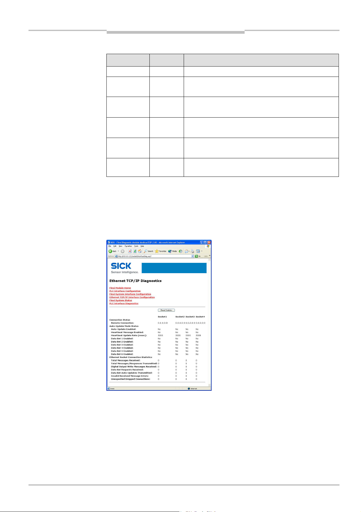
Operating Instructions Chapter 8
Tab.83:
Read Digital Output
Flexi Classic Gateways
Ethernet TCP/IP Gateway
The following response message is sent by UE410-EN to the application.
Setting response
Parameter Length Value
Command WORD 003Fhex = Read digital output settings response
Digital output 1
setting
Digital output 2
setting
Digital output 3
setting
Digital output 4
setting
Sequential
number
WORD 0 = Digital output 1 disabled
1 = Digital output 1 enabled
WORD 0 = Digital output 2 disabled
1 = Digital output 2 enabled
WORD 0 = Digital output 3 disabled
1 = Digital output 3 enabled
WORD 0 = Digital output 4 disabled
1 = Digital output 4 enabled
WORD Response sequential number
8.5 Ethernet TCP/IP interface status and statistics
Open a web browser on a PC in the network and go to the address of the UE410-EN.
Click Ethernet TCP/IP Interface Status and Statistics on the UE410-EN homepage.
The following web page will be displayed:
8011834/YT28/2016-03-15 © SICK AG • Industrial Safety Systems • Germany • All rights reserved
Subject to change without notice
83
Page 84

Chapter 8 Operating Instructions
Tab.84:
Statistical data and
Ethernet TCP/IP Gateway
Flexi Classic Gateways
This page provides the ability to monitor the Socket Interface Communication Status and
Statistics. This page updates automatically every 10 seconds.
diagnostic data of the TCP/IP
Interface
Entry Description
Connection status
Remote Connection Displays the status of the connection in the form of
<ip address:port>. All zeros indicates no connection.
Auto Update Mode status
Auto Update Enabled Indicates Auto Update Mode is enabled on the socket port for one or
more data sets.
Heartbeat Message
Enabled
Heartbeat Update Rate Indicates that Heartbeat Messages containing the enabled data
Data Set 1 Enabled Indicates whether data set 1 will be automatically updated.
Data Set 2 Enabled Indicates whether data set 2 will be automatically updated.
Data Set 3 Enabled Indicates whether data set 3 will be automatically updated.
Data Set 4 Enabled Indicates whether data set 4 will be automatically updated.
Data Set 5 Enabled Indicates whether data set 5 will be automatically updated.
Data Set 6 Enabled Indicates whether data set 6 will be automatically updated.
Ethernet Socket Connection Statistics
Indicates Heartbeat Messages are enabled on the socket port.
set(s) will be transmitted at this rate.
Total Messages Received Displays the total number of messages received on the socket port.
Total Messages/Responses
Transmitted
Digital Output Write
Messages Received
Data Set Requests
Received
Data Set Auto-Updates
Transmitted
Invalid Received Message
Errors
Dropped Connections Displays the number of times the connection was unexpectedly
Displays the total number of messages and responses transmitted
out the socket port.
Displays the number of digital output write messages received on the
socket port.
Displays the number of data set request messages received on the
socket port.
Displays the number of Auto Update data set messages transmitted
out the socket port.
Displays the number of messages received with unknown message
commands or improper formatting.
dropped by the connecting device.
84 © SICK AG • Industrial Safety Systems • Germany • All rights reserved 8011834/YT28/2016-03-15
Subject to change without notice
Page 85
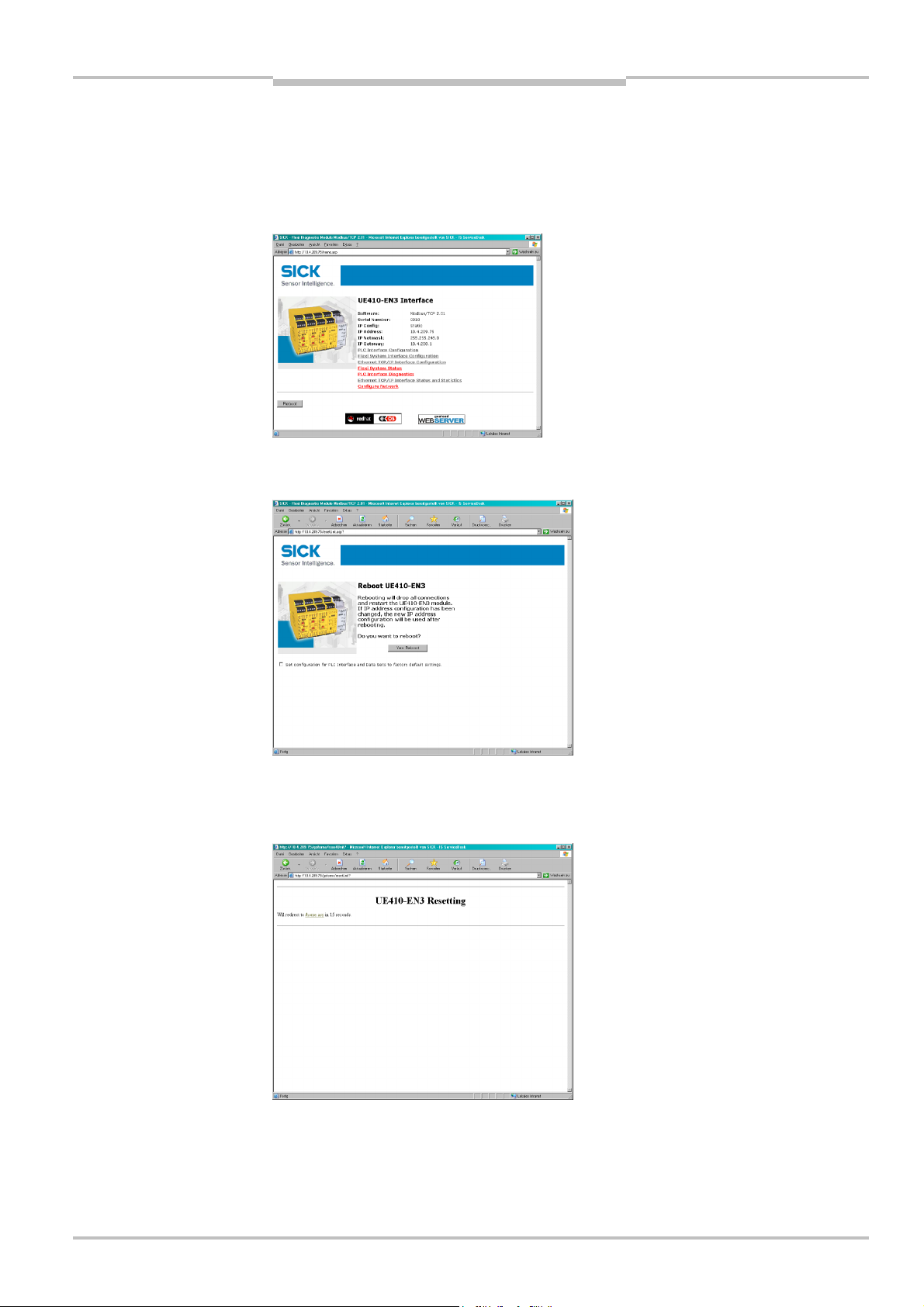
Operating Instructions Chapter 8
Flexi Classic Gateways
Ethernet TCP/IP Gateway
8.6 Resetting to factory settings
he UE410-EN can be reset to the factory settings as follows:
T
Open a web browser on a PC in the same network and go to the address of the
UE410FEN. The following web page is displayed:
Click the reboot button. The following web page is displayed:
Activate Set configuration for PLC Interface and Data Sets to factory default settings.
Click the button Yes: Reboot. The following web page is displayed:
The UE410-EN is reset to the factory settings. The web server of the UE410-EN is called up
again automatically.
8011834/YT28/2016-03-15 © SICK AG • Industrial Safety Systems • Germany • All rights reserved
Subject to change without notice
85
Page 86

Chapter 8 Operating Instructions
Tab.85:
Troubleshooting
Ethernet TCP/IP Gateway
Flexi Classic Gateways
Notes
The only exception is the UE410-EN IP address, which is not reset to factory settings
with this action.
After resetting to factory settings, the UE410-EN does not identify the connected Flexi
Classic module again, but displays all modules as “Unknown Modules”. In addition the
UE410-EN loses the system information MOD-ID, CRC1, CRC2, SWVERSION_H, SWVERSION_L, FUNCTION, KONF, CRC_H CODE and CRC_L CODE and transfers zeros into
the corresponding data sets. Restarting the Flexi Classic system remedies this problem.
Interrupt the power supply of the Flexi Classic system and switch on again.
8.7 Troubleshooting
Error Cause Remedy
The browser does not find
the UE410-EN homepage
during configuration.
UE410-EN has no power
supply.
UE410-EN is not in the same
physical network as the PC.
The PC is configured to another
subnet mask in the TCP/IP
settings.
UE410-EN has already been
configured once and has a
fixed set IP address or an IP
address assigned by a DHCP
server that is not recognised.
Establish the power supply.
Check the Ethernet wiring and
network settings on the PC and
correct if necessary.
Set the subnet mask on the PC to
255.255.0.0 (factory setting of the
UE410FEN).
The software tool Flexi Classic
IPFLink can be used to scan the
network for connected Flexi Classic
modules and to determine the
network address.
UE410-EN does not supply
any data.
LED PWR Green
LED LINK/ACT / Green
LED ERR Green
UE410-EN does not supply
any data.
LED PWR Green
LED LINK/ACT / Green
LED ERR Green
UE410-EN functioned
correctly after configura-
tion, but suddenly no longer
supplies data.
LED PWR Green
LED LINK/ACT / Green
LED ERR Green
UE410-EN is configured to the
operating mode Master (Write
to PLC), but neither Heartbeat
nor Update Immediately on
Status/Configuration Change
are activated.
No data set is activated. Activate at least one data set.
UE410-EN is operated in slave
mode, the IP address is as-
signed from a DHCP server.
After the UE410-EN or the
DHCP server has been restar-
ted, a different IP address that
is unknown to the PLC has
been assigned to the
UE410FEN.
Activate one of the named
functions.
Either assign a fixed IP address to
the UE410FEN, or reserve a fixed IP
address for the UE410FEN in the
DHCP server (manual assignment
by means of the MAC address of
the UE410-EN).
86 © SICK AG • Industrial Safety Systems • Germany • All rights reserved 8011834/YT28/2016-03-15
Subject to change without notice
Page 87

Operating Instructions Chapter 8
Flexi Classic Gateways
Ethernet TCP/IP Gateway
Error Cause Remedy
UE410-EN does not have a
connection to the Flexi
Classic system.
LED PWR Green
LED LINK/ACT / Green
LED ERR Red
UE410-EN is not plugged
properly into the other Flexi
Classic module.
Module connecting plug is
soiled or damaged.
Plug the UE410-EN in correctly,
clean the connecting socket/plug.
UE410-EN does not supply
any data and cannot be
accessed via the web
browser.
LED PWR Green
LED LINK/ACT / Green
LED ERR Red
UE410-EN transfers only
zeros for the system
information MOD-ID, CRC1,
CRC2, SWVERSION_H, SW-
VERSION_L, FUNCTION,
KONF, CRC_H CODE and
CRC_L CODE; all connected
Flexi Classic modules are
only listed as “Unknown
Modules” on the
configuration pages.
Internal device error Switch off the power supply of the
Flexi Classic system and switch it
on again. If the error remains,
replace the gateway.
UE410-EN was reset to the
factory settings, but no hard-
ware reset of the Flexi Classic
systems was carried out.
Switch off the power supply of the
Flexi Classic system and switch on
again.
Symbol description:
LED offGreen: LED lights up green Red: LED flashes red
8011834/YT28/2016-03-15 © SICK AG • Industrial Safety Systems • Germany • All rights reserved
Subject to change without notice
87
Page 88

Chapter 8 Operating Instructions
Tab.86:
Data sets 1
–
5 of the
Ethernet TCP/IP Gateway
Flexi Classic Gateways
8.8 Description of the data sets
8.8.1 Data sets 1-5
The compilation of data sets 1-5 is fixed; these data sets can only be activated or deactivated as a whole. The length of these data sets is always the same. The data will be zeroed
for modules that do not exist.
UE410-EN
Data set 1 Data set 2 Data set 3 Data set 4 Data set 5
Input data Output data Gateway-
specific
diagnostic
data
Byte 1 MED1 MQD1 DIG_OUT1 BAS1 MFD1
Byte 2 MED2 MQD2 DIG_OUT2 Backplane
Byte 3 MED3 MQD3 – CRC1 MFD3
Byte 4 MED4 MQD4 – CRC2 MFD4
Byte 5 MED5 MQD5 – – MFD5
Byte 6 MED6 MQD6 – – MFD6
Byte 7 MED7 MQD7 – – MFD7
Byte 8 MED8 MQD8 – – MFD8
Byte 9 MED9 MQD9 – – MFD9
Byte 10 MED10 MQD10 – – MFD10
Byte 11 MED11 MQD11 – – MFD11
Byte 12 MED12 MQD12 – – MFD12
Byte 13 MED13 MQD13 – – MFD13
General
diagnostic
data
Fault
Module-specific
diagnostic data
MFD2
Byte 14 0* 0* – – 0*
Byte 15-18 – – – – MFCLASS1/ CODE1,
MFCLASS2/CODE2 (1)
Byte 19-22 – – – – MFCLASS1/ CODE1,
MFCLASS2/CODE2 (2)
Byte 23-26 – – – – MFCLASS1/ CODE1,
MFCLASS2/CODE2 (3)
Byte 27-30 – – – – MFCLASS1/ CODE1,
MFCLASS2/CODE2 (4)
Byte 31-34 – – – – MFCLASS1/ CODE1,
MFCLASS2/CODE2 (5)
Byte 35-38 – – – – MFCLASS1/ CODE1,
MFCLASS2/CODE2 (6)
Byte 39-42 – – – – MFCLASS1/ CODE1,
MFCLASS2/CODE2 (7)
Byte 43-46 – – – – MFCLASS1/ CODE1,
MFCLASS2/CODE2 (8)
88 © SICK AG • Industrial Safety Systems • Germany • All rights reserved 8011834/YT28/2016-03-15
Subject to change without notice
Page 89

Operating Instructions Chapter 8
Flexi Classic Gateways
Ethernet TCP/IP Gateway
Data set 1 Data set 2 Data set 3 Data set 4 Data set 5
Input data Output data Gateway-
specific
diagnostic
data
Byte 47-50 – – – – MFCLASS1/ CODE1,
Byte 51-54 – – – – MFCLASS1/ CODE1,
Byte 55-58 – – – – MFCLASS1/ CODE1,
Byte 59-62 – – – – MFCLASS1/ CODE1,
Byte 63-66 – – – – MFCLASS1/ CODE1,
Length 14 Bytes 14 Bytes 2 Bytes 4 Bytes 66 Bytes
General
diagnostic
data
Module-specific
diagnostic data
MFCLASS2/CODE2 (9)
MFCLASS2/CODE2 (10)
MFCLASS2/CODE2 (11)
MFCLASS2/CODE2 (12)
MFCLASS2/CODE2 (13)
* Inserted for byte alignment
8011834/YT28/2016-03-15 © SICK AG • Industrial Safety Systems • Germany • All rights reserved
Subject to change without notice
89
Page 90

Chapter 8 Operating Instructions
Tab.87:
Data set 6 of the
Ethernet TCP/IP Gateway
Flexi Classic Gateways
8.8.2 Data set 6, can be compiled by the user
The contents of Data set 6 can be compiled by the user.
If the option Return only enabled Data is activated in the configuration of the data set
(see section “Configuration …” above), the data set can have a different length depending
on the compilation. The maximum length is 124 bytes. The minimum length is 2 bytes.
The selected data are transferred for all Flexi Classic modules respectively.
The data are zeroed for modules that do not exist.
Note
If data is expected in 16-bit words and in the format Big Endian (e.g. Modbus/TCP), it is
transferred with the more significant byte first.
UE410-EN
Byte
1-124
Data set 6
CRC-H CRC-L
MKD1.1 MKD2.1 MKD1.2 MKD2.2 MKD1.3 MKD2.3
MKD1.4 MKD2.4 MKD1.5 MKD2.5 MKD1.6 MKD2.6
MKD1.7 MKD2.7 MKD1.8 MKD2.8 MKD1.9 MKD2.9
MKD1.10 MKD2.10 MKD1.11 MKD2.11 MKD1.12 MKD2.12
MKD1.13 MKD2.13
MOD-ID1 MOD-ID2 MOD-ID3 MOD-ID4 MOD-ID5 MOD-ID6
MOD-ID7 MOD-ID8 MOD-ID9 MOD-ID10 MOD-ID11 MOD-D12
MOD-13 0
SW Version
Byte 1,
Module 1
SW Version
Byte 1,
Module 4
SW Version
Byte 1,
Module 7
SW Version
Byte 2,
Module 1
SW Version
Byte 2,
Module 4
SW Version
Byte 2,
Module 7
SW Version
Byte 1,
Module 2
SW Version
Byte 1,
Module 5
SW Version
Byte 1,
Module 8
SW Version
Byte 2,
Module 2
SW Version
Byte 2,
Module 5
SW Version
Byte 2,
Module 8
SW Version
Byte 1,
Module 3
SW Version
Byte 1,
Module 6
SW Version
Byte 1,
Module 9
SW Version
Byte 2,
Module 3
SW Version
Byte 2,
Module 6
SW Version
Byte 2,
Module 9
SW Version
Byte 1,
Module 10
SW Version
Byte 1,
Module 13
Function 1 Function 2 Function 3 Function 4 Function 5 Function 6
Function 7 Function 8 Function 9 Function 10 Function 11 Function 12
Function 13 0
SW Version
Byte 2,
Module 10
SW Version
Byte 2,
Module 13
SW Version
Byte 1,
Module 11
SW Version
Byte 2,
Module 11
SW Version
Byte 1,
Module 12
SW Version
Byte 2,
Module 12
90 © SICK AG • Industrial Safety Systems • Germany • All rights reserved 8011834/YT28/2016-03-15
Subject to change without notice
Page 91

Operating Instructions Chapter 8
Flexi Classic Gateways
Ethernet TCP/IP Gateway
Data set 6
Conf 1 Conf 2 Conf 3 Conf 4 Conf 5 Conf 6
Conf 7 Conf 8 Conf 9 Conf 10 Conf 11 Conf 12
Conf 13 0
CRC
Byte 1,
Module 1
CRC
Byte 2,
Module 1
CRC
Byte 1,
Module 2
CRC
Byte 2,
Module 2
CRC
Byte 1,
Module 3
CRC
Byte 2,
Module 3
CRC
Byte 1,
Module 4
CRC
Byte 1,
Module 7
CRC
Byte 1,
Module 10
CRC
Byte 1,
Module 13
DIAG
Version
Byte 1
CRC
Byte 2,
Module 4
CRC
Byte 2,
Module 7
CRC
Byte 2,
Module 10
CRC
Byte 2,
Module 13
DIAG
Version
Byte 2
CRC
Byte 1,
Module 5
CRC
Byte 1,
Module 8
CRC
Byte 1,
Module 11
CRC
Byte 2,
Module 5
CRC
Byte 2,
Module 8
CRC
Byte 2,
Module 11
CRC
Byte 1,
Module 6
CRC
Byte 1,
Module 9
CRC
Byte 1,
Module 12
CRC
Byte 2,
Module 6
CRC
Byte 2,
Module 9
CRC
Byte 2,
Module 12
8011834/YT28/2016-03-15 © SICK AG • Industrial Safety Systems • Germany • All rights reserved
Subject to change without notice
91
Page 92

Chapter 9 Operating Instructions
Fig.19:
Interfaces and
Terminals of digital control
RJ45
Ethernet socket
RJ45 Ethernet socket
LED power supply (green)
LED network activity for
LED Error (red/green)
EtherNet/IP Gateway
Flexi Classic Gateways
9 EtherNet/IP Gateway
he following Flexi Classic gateway can be used for EtherNet/IP: UE410-EN1
T
The UE410-EN1 will support only EtherNet/IP explicit messaging. Class 1 messaging is not
supported. The EDS file is available on www.sick.com.
9.1 Interfaces and operation
The UE410-EN is equipped with four digital control outputs X1–X4.
The UE410-EN is equipped with an integrated 3-port switch for connection with the Ethernet network. Two RJ45 sockets are available for the connection. The switch functionality
allows the UE410-EN to be used for connection to another Ethernet component (e.g. connection to a notebook) without having to interrupt the Ethernet connection to the network.
display elements of the
UE410-EN
outputs X1–X4
Ethernet port 1 or 2 (green)
92 © SICK AG • Industrial Safety Systems • Germany • All rights reserved 8011834/YT28/2016-03-15
Subject to change without notice
Page 93

Operating Instructions Chapter 9
Tab.88:
Meaning of the LED
Flexi Classic Gateways
EtherNet/IP Gateway
displays
Note
LED Meaning
No power supply PWR
Green Power supply switched on
LINK/ACT 1
LINK/ACT 2
No Ethernet connection
Green Ethernet connection active, no data transmission
Green Ethernet connection active, data transmission
No power supply ERR
Green Gateway operating, no error message, at least one
Ethernet connection exists
Green Gateway operating, valid IP address assigned, configu-
ration is valid, but no Ethernet connection established.
All data sets are deactivated
Red No flex bus communication
Red Internal device error
Red/Green Self-test of the gateway after switching on the power
supply on the Flexi Classic system
Symbol description:
LED off Green: LED lights up green Red: LED flashes red
Error elimination is described in section “Troubleshooting” below.
9.2 Basic configuration — assigning an IP address
Configuration of the UE410-EN is performed browser-supported via the integrated web
server of the gateway.
Ensure that the UE410-EN is installed correctly, energised and connected with the
Ethernet network.
Open a web browser on a PC in the same network and go to the address of the
UE410FEN. Upon delivery, the UE410-EN is configured for the following address:
– IP address 192.168.250.250
– Subnet mask 255.255.0.0
– Default gateway 0.0.0.0
The following web page is displayed:
8011834/YT28/2016-03-15 © SICK AG • Industrial Safety Systems • Germany • All rights reserved
Subject to change without notice
93
Page 94

Chapter 9 Operating Instructions
Note
Note
EtherNet/IP Gateway
Flexi Classic Gateways
To assign a suitable IP address within the network to the UE410-EN, click Configure
Network. The following web page is displayed:
The UE410-EN network address can be obtained automatically or configured manually.
For automatic assignment of the network address, choose Use DHCP.
A DHCP server must be active in the network so that these functions can be used. A new IP
address will be assigned to the UE410-EN when the DHCP server or the UE410-EN is
restarted. When the UE410-EN is operated in slave mode (see section “Configuration …”
below) and the IP address changes due to a restart, the PLC can no longer communicate
with the UE410-EN. If you use the Use DHCP function in combination with the slave mode
of the UE410-EN, we recommend that you reserve a specific IP address for the UE410-EN
(manual assignment on the basis of the MAC address of the UE410-EN).
In order to set the network address manually, choose Use static configuration below
and enter a valid free IP address, the subnet mask and the IP address of the network
gateway.
Finalise changes by clicking Save.
The new network address is saved in the UE410-EN flash memory, but will only become
effective after the gateway has been restarted. In order to restart the gateway, …
either click the Reboot button on the homepage of the UE410-EN main page
or interrupt the power supply of the Flexi Classic system and switch on again.
Call up the new address of the UE410-EN in order to configure the UE410-EN in the web
browser further.
If a DHCP server is used to assign an IP address, the new address is unknown to the
system administrator. It can be read out in the administration pages of the DHCP server.
Alternatively the software tool Flexi Classic IP-Link can be used. This scans the network for
Flexi Classic modules and registers their IP addresses.
9.3 Device name
Device serial number as well as the device MAC address allow unique identification of the
device. However in some applications it is useful to assign a more significant device name
for better device identification in the field. This is why the UE410-EN supports the configuration of an individual device name.
Click Configure Device Name on the UE410-EN homepage.
Enter the device name (maximum length 256 characters).
Click Save.
The device name will now appear next to “Device Name” on the UE410-EN homepage.
94 © SICK AG • Industrial Safety Systems • Germany • All rights reserved 8011834/YT28/2016-03-15
Subject to change without notice
Page 95

Operating Instructions Chapter 9
Tab.89:
Number of possible
Flexi Classic Gateways
EtherNet/IP Gateway
9.4 Configuration of the interface to the PLC — how the
data are transferred
The configuration steps in this section specify how the data on the higher-level PLC are
ransferred. Different operating modes can be selected to this purpose. The number of
t
possible connections to the PLC depends on whether the UE410-EN1 is operated as a
master or slave. Depending on the setting, up to 128 PLCs can address the UE410-EN1 at
the same time.
connections
Operating mode of the UE410-EN Maximum connections
Rx (To PLC) Transfer Mode: Write-to-Tag/File
Tx (From PLC) Transfer Mode: Read-from-Tag/File
Rx (To PLC) Transfer Mode: Write-to-Tag/File
Tx (From PLC) Transfer Mode: PLC Writes
Rx (To PLC) Transfer Mode: Polling
Tx (From PLC) Transfer Mode: Read-from-Tag/File
Rx (To PLC) Transfer Mode: Polling
Tx (From PLC) Transfer Mode: PLC Writes
Rx and Tx: 1
Rx: 1
Tx: 127
Rx: 127
Tx: 1
Rx and Tx: 128
Open a web browser on a PC in the network and go to the address of the UE410-EN.
Click PLC Interface Configuration on the UE410-EN homepage. The following web page
is displayed:
8011834/YT28/2016-03-15 © SICK AG • Industrial Safety Systems • Germany • All rights reserved
Subject to change without notice
The page shows the current settings of the interface to the PLC.
95
Page 96
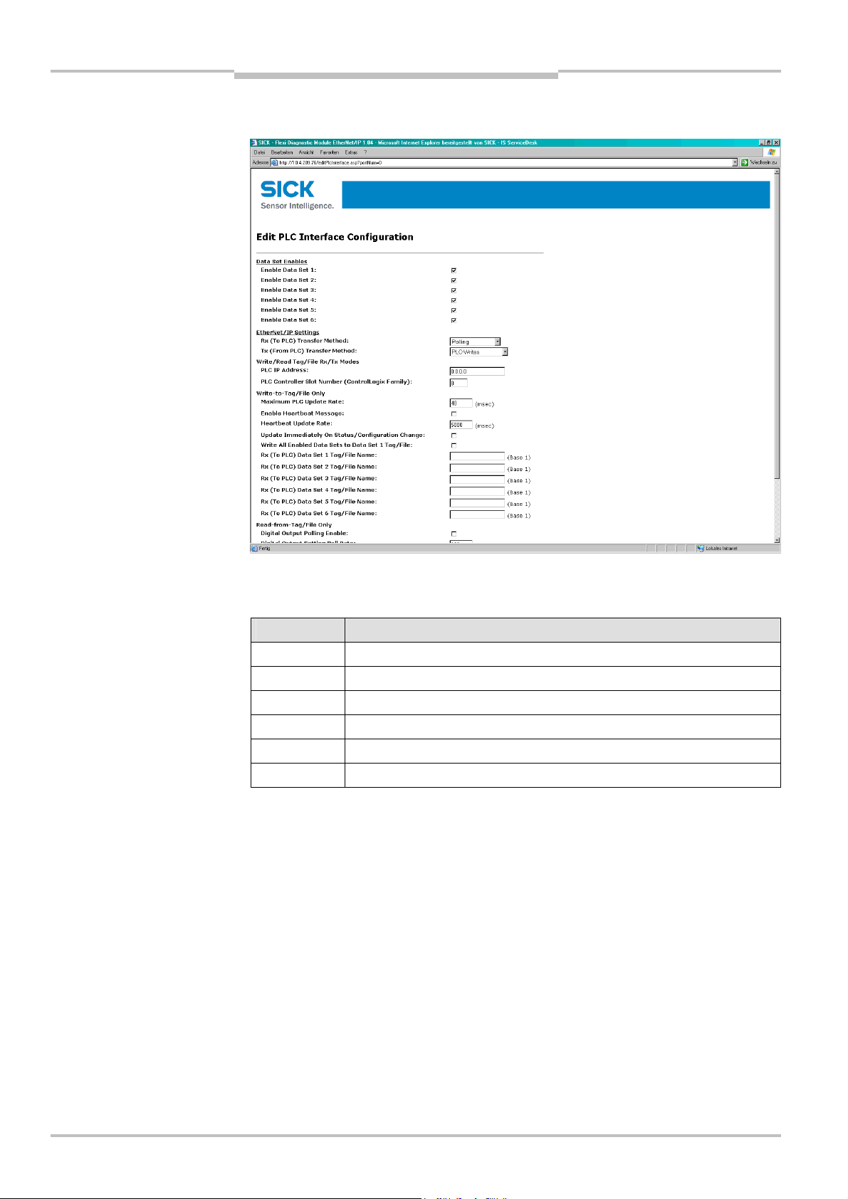
Chapter 9 Operating Instructions
Tab.90:
Data sets 1
–
6 of
EtherNet/IP Gateway
Flexi Classic Gateways
Click Edit to change the settings. The following web page is displayed:
UE410-EN1 in overview
Decide, which of the following 6 data sets are to be transferred to the PLC. For the exact
description of the data sets please refer to section “Description of the data sets” below.
Data set Description
1 Module-specific input data
2 Module-specific output data
3 Module-specific data of the UE410-EN gateway
4 General status and configuration data
5 Diagnostics data
6 Configuration data of the Flexi Classic system, user defined compilation
Select the desired data sets.
After the data sets have been selected, configure how they should be sent to the PLC.
For this purpose certain parameters that depend on the operating mode have to be set.
These are described below.
96 © SICK AG • Industrial Safety Systems • Germany • All rights reserved 8011834/YT28/2016-03-15
Subject to change without notice
Page 97

Operating Instructions Chapter 9
Tab.91:
Configu
ration of the
Flexi Classic Gateways
EtherNet/IP Gateway
Overview of the selection and entry fields:
interface to the PLC
Selection/entry
window
Rx (To PLC)
Transfer Mode
Tx (From PLC)
Transfer Mode
Settings for the operating modes Write-to-Tag/File and/or Read-from-Tag/file:
PLC IP Address 0.0.0.0 Specifies the PLC address in standard format xxx.xxx.xxx.xxx.
PLC Controller Slot
Number
Factory
setting
Polling Determines the type of data transfer from
PLC Writes Determines the type of data transfer from the PLC
0 Specifies the PLC slot number of the controller (typically 0).
Description
See
UE410FEN1 to the PLC.
Polling — PLC requests the data.
Write-to-Tag/File — UE410-EN1 writes the data to
the PLC memory.
Off — PLC Interface disabled.
to UE410-EN1.
PLC Writes — PLC writes to the UE410-EN1
memory.
Read-from-Tag/file — UE410-EN1 requests data
continuously from the PLC.
Off — PLC Interface disabled.
The selected data sets are transferred to this IP Address.
section
9.4.1
See
section
9.4.2
Settings for the operating mode Write-to-Tag/File:
Maximum PLC
Update Rate
Enable Heartbeat
Message
Heartbeat Update
Interval
40 Defines the maximum rate (the minimum time interval) for
sending the data sets to the PLC. Settings occur dependent on
the PLC processing speed.
Minimum = 10 ms, maximum = 65535 ms. The default value of
40 ms is suitable for most PLCs.
Note: If this value is greater than the Heartbeat Update Interval,
the Heartbeat Update Interval is increased (slowed down) to
this value.
Deactivated
5000 Specifies the Heartbeat Update Interval in milliseconds with
Activates updating of the active data sets with the set
Heartbeat Update Rate.
Note: Either this option or Update Immediately on Status/Confi-
guration Change must be activated, otherwise no data will be
transferred!
which the data are updated in the PLC.
Standard = 5000 ms, Minimum = 10 ms, Maximum
= 65535 ms.
Note: If the Maximum PLC Update Rate is larger than the
Heartbeat Update Rate, the Heartbeat Update Rate is in-
creased (slowed down) to this value.
Update
Immediately on
Status/Configu-
ration Change
8011834/YT28/2016-03-15 © SICK AG • Industrial Safety Systems • Germany • All rights reserved
Subject to change without notice
Deactivated
Specifies whether the UE410-EN is to update the data in the
PLC immediately when changes occur in the data sets. If not
activated, the update is carried out with the next Heartbeat
Interval.
Note: Either this option or Enable Heartbeat Message must be
activated, otherwise no data will be transferred!
97
Page 98

Chapter 9 Operating Instructions
EtherNet/IP Gateway
Flexi Classic Gateways
Selection/entry
window
Write All Enabled
Data Sets to Data
Set 1 Tag/File
Rx Data Set
Tag/File Names
Digital Output
Polling Enable
Digital Output
Tag/File Name
Digital Output
Setting Polling
Rate
Factory
setting
Deactivated Specifies whether to write all enabled data sets to the Data Set
1 Specifies the tag or file names on the PLC where the data sets
Settings for the operating mode Read-from-Tag/file:
Deactivated
Specifies the PLC tag or file name where the UE410-EN will
200 Specifies the interval in milliseconds in which the value of the
Description
1 Tag/File address. If selected, the first 16 bit word will contain
an incrementing sequence number and all enabled data sets
will follow in order.
are to be sent to.
For ControlLogix PLCs, the tag names must be controller wide
and must be an array of type INT (16 bit word) large enough to
hold the entire data set message.
For SLC/PLC-5 PLCs, the file names must begin with a “$”
(i.e. $N10:0).
For MicroLogix PLCs, the file names must begin with a “#”
(i.e. #N10:0).
Specifies whether the UE410-EN1 is to request the value of the
digital outputs from the PLC.
request the Digital output values.
For ControlLogix PLCs, the tag names must be controller wide
and be of either SINT, INT, DINT, or BOOL[32] bit array.
For SLC, PLC-5, or MicroLogix PLCs, the file data type must be
either Integer (N) or Binary (B).
The same file naming rules apply as for the Tag/File names.
digital outputs is requested.
Minimum = 10 ms., Maximum = 65535 ms.
Note
Note
All data sets are transferred to the PLC in 16 bit integer format with the first byte placed in
the most significant, or leftmost byte of the integer.
9.4.1 Operating modes in the transfer mode Rx (to PLC)
Polling — PLC requests the data from UE410-EN
In this operating mode the UE410-EN sends the data as slave upon request from the PLC.
If this operating mode is desired:
Chose the operating mode Polling in the Rx (To PLC) Ethernet Transfer Method
selection field. All further settings do not apply.
Activate Save in Flash and click Submit to save the selection.
Only if Save in Flash is checked will the new configuration be stored in the UE410-EN’s
non-volatile memory and be available after a restart of the gateway. Submit without
checking Save in Flash allows, for example, the testing of new configurations without
overwriting the old configuration.
98 © SICK AG • Industrial Safety Systems • Germany • All rights reserved 8011834/YT28/2016-03-15
Subject to change without notice
Page 99

Operating Instructions Chapter 9
Flexi Classic Gateways
Note
EtherNet/IP Gateway
The UE410-EN1 supports two vendor specific objects which can be polled via explicit
messaging.
The Full Data Set Transfer Object allows to poll for each of the data sets as defined in
section 9.7.1. There is one instance where each attribute represents a data set.
The Individual Data Set Transfer Object allows to poll for the individual data set para-
meters as defined in section 9.7.2. There is one instance per data set and each
attribute represents a data set parameter.
Write-to-Tag/File — UE410-EN writes the data to the PLC memory
In this operating mode the UE410-EN as a master writes the data of all the activated data
sets in the specified memory areas of the PLC. If this operating mode is desired:
Chose the operating mode Write-to-Tag/File in the Rx (To PLC) Ethernet Transfer
Method selection field.
Carry out the following settings on the same web page (see Tab. 91):
– PLC IP Address
– PLC controller Slot Number
– Maximum PLC Update Rate
– Enable Heartbeat Message (either this option or Update Immediately on
Status/Configuration Change must be activated!)
– Heartbeat Update Rate (if Enable Heartbeat Message is activated)
– Update Immediately on Status/Configuration Change (either this option or Enable
Heartbeat Message must be activated!)
– Write all Enabled Data Sets to Data Set 1 Tag/File
– Rx (To PLC) Data Set N PLC Tag/File Name — for all activated data sets
Activate Save in Flash and click Submit to save the selection.
Only if Save in Flash is checked, will the new configuration be stored in the UE410-EN’s
non-volatile memory and be available after a restart of the gateway. Submit without
checking Save in Flash allows, for example, the testing of new configurations without
overwriting the old configuration.
Note
9.4.2 Operating modes in the transfer mode Tx (from PLC)
PLC writes — PLC sends digital output data to the UE410-EN
In this operating mode the PLC sends writing requirements as master to the UE410-EN in
order to set the digital outputs. If this operating mode is desired:
Chose the operating mode PLC Writes in the Tx (from PLC) Transfer Mode selection
field. All the further settings do not apply.
Activate Save in Flash and click Submit to save the selection.
Only if Save in Flash is checked, will the new configuration be stored in the UE410-EN’s
non-volatile memory and be available after a restart of the gateway. Submit without
checking Save in Flash allows, for example, the testing of new configurations without
overwriting the old configuration.
The UE410-EN1 supports one vendor specific object which can be used to control the
digital outputs via explicit messaging: The Discrete Output Point Object allows to control
the digital outputs. There is one instance per output where one attribute is used to control
the output and one attribute represents the current setting of the output.
For a detailed description of the Discrete Output Point Object please refer to section 9.7.3.
8011834/YT28/2016-03-15 © SICK AG • Industrial Safety Systems • Germany • All rights reserved
Subject to change without notice
99
Page 100

Chapter 9 Operating Instructions
Note
EtherNet/IP Gateway
Flexi Classic Gateways
Read-from-Tag/file — UE410-EN requests the data from the PLC.
In this operating mode the UE410-EN as master requests the data continuously from the
LC in order to set the digital outputs. If this operating mode is desired:
P
Select the operating mode Read-from-Tag/File in the Tx (from PLC) Transfer Mode
selection field.
Carry out the following settings on the same web page (see Tab. 91):
– PLC IP Address
– PLC Controller Slot Number
– Digital Output Polling Enable
– Digital Output Tag/File Name
– Digital Output Setting Poll Rate
Activate Save in Flash and click Submit to save the selection.
Only if Save in Flash is checked, the new configuration will be stored in the UE410-EN’s
non-volatile memory and be available after a restart of the gateway. Submit without
checking Save in Flash allows, for example, the testing of new configurations without
overwriting the old configuration.
9.5 Configuration of the gateway — which data are
transferred
The UE410-EN processes the data of a Flexi Classic system and makes them available in
different compilations, the data sets for the PLC.
There are 6 data sets available to this purpose: Data sets 1-5 contain fixed data compilations, Data set 6 can be configured by the user. The data sets that are to be transferred to
the PLC must be activated (see section 7.8).
Open a web browser on a PC in the network and go to the address of the UE410-EN.
Click Flexi System Interface Configuration on the UE410-EN homepage.
The following web page is displayed:
The installed Flexi Classic modules are recognised automatically and listed in the Flexi
Chassis Configuration field. Modules of the next Flexi Classic generation that are not yet
recognised by the UE410-EN1 are listed as “Unknown Module”. The corresponding front
and the data structure of the module can be displayed by clicking a module. In the example, a click on Module 1 displays a new window with the corresponding information. The
window can subsequently be closed again.
100 © SICK AG • Industrial Safety Systems • Germany • All rights reserved 8011834/YT28/2016-03-15
Subject to change without notice
 Loading...