

Page 1

FlexChain
O P E R A T I N G I N S T R U C T I O N S
Page 2

Described product
2006/42/EG
NO
SAFETY
FlexChain
Manufacturer
SICK AG
Erwin-Sick-Str. 1
79183 Waldkirch
Germany
Legal information
This work is protected by copyright. Any rights derived from the copyright shall be
reserved for SICK AG. Reproduction of this document or parts of this document is only
permissible within the limits of the legal determination of Copyright Law. Any modifica‐
tion, abridgment or translation of this document is prohibited without the express writ‐
ten permission of SICK AG.
The trademarks stated in this document are the property of their respective owner.
© SICK AG. All rights reserved.
Original document
This document is an original document of SICK AG.
2
O PE R AT I NG IN S TR U CT I ON S | FlexChain 8023047/2018-11-15 | SICK
Subject to change without notice
Page 3

Contents
CONTENTS
1 About this document........................................................................ 5
1.1 Information on the operating instructions.............................................. 5
1.2 Scope......................................................................................................... 5
1.3 Explanation of symbols............................................................................ 5
1.4 Customer service...................................................................................... 6
2 Safety information............................................................................ 7
2.1 Intended use............................................................................................. 7
2.2 Limitation of liability................................................................................. 7
2.3 Requirements for skilled persons and operating personnel.................. 7
2.4 Hazard warnings and operational safety................................................. 8
2.5 Repair........................................................................................................ 8
3 Product description........................................................................... 9
3.1 Product ID.................................................................................................. 9
3.1.1 Type labels................................................................................ 9
3.2 Product features and functions............................................................... 9
3.2.1 Device view............................................................................... 9
4 Mounting............................................................................................. 11
4.1 Scope of delivery....................................................................................... 11
4.2 Installation requirements......................................................................... 11
4.3 Installing the system................................................................................. 11
5 Electrical installation........................................................................ 12
5.1 Notes on electrical installation................................................................ 12
5.2 Schematic arrangement........................................................................... 13
5.3 Pin assignment of the connections......................................................... 14
5.4 Connecting the supply voltage................................................................. 15
5.5 Digital interfaces....................................................................................... 16
6 Commissioning.................................................................................. 17
6.1 Simplified illustration................................................................................ 17
7 Operation............................................................................................ 20
7.1 Configuration via SOPAS ET..................................................................... 20
7.1.1 Home........................................................................................ 20
7.1.2 Teach & Positioning................................................................. 21
7.1.3 Zones........................................................................................ 24
7.1.4 Logics........................................................................................ 27
7.1.5 PINS.......................................................................................... 28
7.1.6 Process data............................................................................ 29
7.1.7 Settings.................................................................................... 31
8 Troubleshooting................................................................................. 32
8023047/2018-11-15 | SICK O P ER A TI N G I NS T RU C TI O NS | FlexChain
Subject to change without notice
3
Page 4

CONTENTS
9 Maintenance...................................................................................... 33
9.1 Maintenance............................................................................................. 33
10 Decommissioning............................................................................. 34
10.1 Disassembly and disposal....................................................................... 34
10.2 Returning devices..................................................................................... 34
11 Technical data.................................................................................... 35
11.1 Host performance..................................................................................... 35
11.2 Host interfaces.......................................................................................... 35
11.3 Host software features............................................................................. 36
11.4 System response time.............................................................................. 36
11.5 Mechanics/electronics/host.................................................................... 36
11.6 Technical data guests............................................................................... 37
11.6.1 General data GL6-C................................................................. 37
11.6.2 General data GSE6-C.............................................................. 38
11.6.3 General data GTB6-C............................................................... 38
11.7 Dimensional drawings.............................................................................. 38
11.8 FlexChain host membrane keyboards..................................................... 41
12 Accessories........................................................................................ 42
13 Annex.................................................................................................. 43
13.1 EU declaration of conformity and certificates........................................ 43
4
O PE R AT I NG IN S TR U CT I ON S | FlexChain 8023047/2018-11-15 | SICK
Subject to change without notice
Page 5

1 About this document
1.1 Information on the operating instructions
These operating instructions provide important information on how to use devices from
SICK AG.
Prerequisites for safe work are:
Compliance with all safety notes and handling instructions supplied
•
Compliance with local work safety regulations and general safety regulations for
•
device applications
The operating instructions are intended to be used by qualified personnel and electrical
specialists.
NOTE
Read these operating instructions carefully before starting any work on the device, in
order to familiarize yourself with the device and its functions.
The instructions constitute an integral part of the product and are to be stored in the
immediate vicinity of the device so they remain accessible to staff at all times. Should
the device be passed on to a third party, these operating instructions should be handed
over with it.
ABOUT THIS DOCUMENT 1
These operating instructions do not provide information on operating the machine in
which the device is integrated. For information about this, refer to the operating instruc‐
tions of the specific machine.
1.2 Scope
These operating instructions serve to incorporate the device into a customer system.
Instructions are given in stages for all actions required.
These instructions apply to all listed device variants of the product.
Available device variants are listed on the online product page.
www.sick.com/FlexChain
b
Commissioning is described using one particular device variant as an example.
1.3 Explanation of symbols
Warnings and important information in this document are labeled with symbols. The
warnings are introduced by signal words that indicate the extent of the danger. These
warnings must be observed at all times and care must be taken to avoid accidents, per‐
sonal injury, and material damage.
DANGER
… indicates a situation of imminent danger, which will lead to a fatality or serious
injuries if not prevented.
WARNING
… indicates a potentially dangerous situation, which may lead to a fatality or serious
injuries if not prevented.
8023047/2018-11-15 | SICK O P ER A TI N G I NS T RU C TI O NS | FlexChain
Subject to change without notice
5
Page 6

1 ABOUT THIS DOCUMENT
CAUTION
… indicates a potentially dangerous situation, which may lead to minor/slight injuries if
not prevented.
NOTICE
… indicates a potentially harmful situation, which may lead to material damage if not
prevented.
NOTE
… highlights useful tips and recommendations as well as information for efficient and
trouble-free operation.
1.4 Customer service
If you require any technical information, our customer service department will be happy
to help. To find your agency, see the final page of this document.
NOTE
Before calling, make a note of all type label data such as type code, serial number, etc.,
to ensure faster processing.
6
O PE R AT I NG IN S TR U CT I ON S | FlexChain 8023047/2018-11-15 | SICK
Subject to change without notice
Page 7

2 Safety information
2.1 Intended use
The FlexChain is a sensor system comprising a central unit (host) and connected guests
(sensors) that is used for optical and non-contact detection of objects.
The FlexChain must be mounted and installed according to these operating instruc‐
tions, and may only be operated according to its intended function.
The FlexChain is not equipped with any direct safety devices. The system designer must
provide measures to ensure the safety of persons and systems in accordance with the
legal guidelines.
Sick AG assumes no liability for losses or damage arising from the use of the product,
either directly or indirectly. This applies in particular to use of the product that does not
conform to its intended purpose and is not described in this documentation.
2.2 Limitation of liability
Applicable standards and regulations, the latest state of technological development,
and our many years of knowledge and experience have all been taken into account
when assembling the data and information contained in these operating instructions.
The manufacturer accepts no liability for damage caused by:
SAFETY INFORMATION 2
■
Failure to observe the operating instructions
■
Improper use
■
Use by untrained personnel
■
Unauthorized conversions
■
Technical modifications
■
Use of unauthorized spare parts, wear and tear parts, and accessories
With special variants, where optional extras have been ordered, or owing to the latest
technical changes, the actual scope of delivery may vary from the features and illustra‐
tions shown here.
2.3 Requirements for skilled persons and operating personnel
WARNING
Risk of injury due to insufficient training!
Improper handling of the device may result in considerable personal injury and material
damage.
■
All work must only ever be carried out by the stipulated persons.
The operating instructions state the following qualification requirements for the various
areas of work:
8023047/2018-11-15 | SICK O P ER A TI N G I NS T RU C TI O NS | FlexChain
Subject to change without notice
7
Page 8

2 SAFETY INFORMATION
■
■
■
The following qualifications are required for various activities:
Activities Qualification
Mounting, maintenance
Electrical installation,
device replacement
Commissioning,
configuration
Operation of the devices in
their particular application
Instructed personnel have been briefed by the operating entity about the tasks
assigned to them and about potential dangers arising from improper action.
Skilled personnel have the specialist training, skills, and experience, as well as
knowledge of the relevant regulations, to be able to perform tasks assigned to
them and to detect and avoid any potential dangers independently.
Electricians have the specialist training, skills, and experience, as well as knowl‐
edge of the relevant standards and provisions to be able to carry out work on elec‐
trical systems and to detect and avoid any potential dangers independently. In Ger‐
many, electricians must meet the specifications of the BGV A3 Work Safety Regu‐
lations (e.g., Master Electrician). Other relevant regulations applicable in other
countries must be observed.
Basic practical technical training
■
Knowledge of the current safety regulations in the workplace
■
Practical electrical training
■
Knowledge of current electrical safety regulations
■
Knowledge of the operation and control of the devices in their
■
particular application
Basic knowledge of the design and setup of the described con‐
■
nections and interfaces
Basic knowledge of data transmission
■
Knowledge of the operation and control of the devices in their
■
particular application
Knowledge of the operation and control of the devices in their
■
particular application
Knowledge of the software and hardware environment in the
■
application
2.4 Hazard warnings and operational safety
Please observe the safety notes and the warnings listed here and in other chapters of
these operating instructions to reduce the possibility of risks to health and avoid dan‐
gerous situations.
2.5 Repair
The product is a replacement device. The device is not intended to be repaired. Interfer‐
ence with or modifications to the device on the part of the customer will invalidate any
warranty claims against SICK AG.
8
O PE R AT I NG IN S TR U CT I ON S | FlexChain 8023047/2018-11-15 | SICK
Subject to change without notice
Page 9
3 Product description
4
3
1
2
6
5
3.1 Product ID
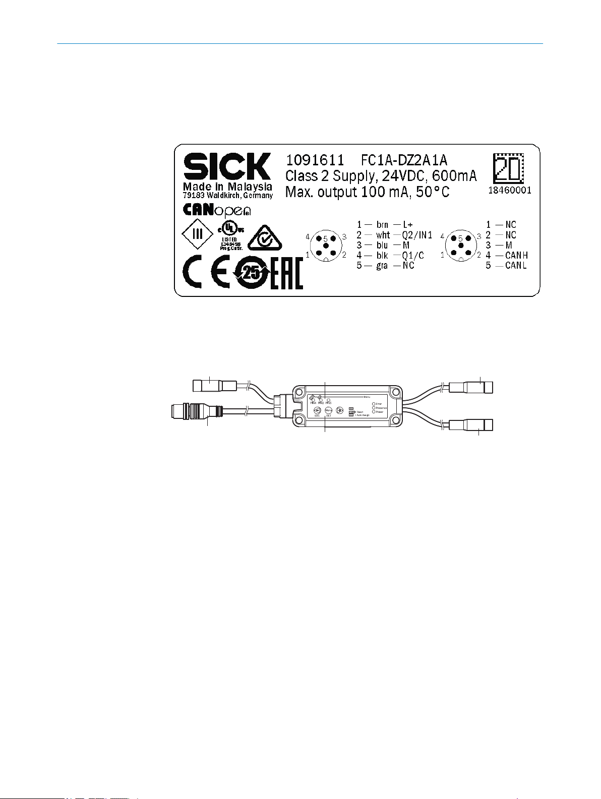
3.1.1 Type labels
PRODUCT DESCRIPTION 3
3.2 Product features and functions
3.2.1 Device view
Figure 1: FlexChain host
Port-A, pigtail M8, 4-pin, female
1
Port B, pigtail M8, 4-pin, female
2
PLC, pigtail M12, 5-pin / 8-pin, male
3
USB, pigtail M8, 4-pin, female
4
Control panel
5
Structure
A FlexChain system comprises a host and a number of guests (sensors). As shown in
the image below, the system components are connected sequentially (bus topology). A
system comprises a host and at least one guest. Up to 60 guests in total can be con‐
nected to a host.
Function
The FlexChain system operates similarly to a light grid. That is, each individual channel
in the system is processed sequentially. This principle means that only one channel at a
time is active. Consequently, there is no possibility of mutual interference within a sys‐
tem, and the guests can be installed arbitrarily close to one another without any inter‐
ference occurring. Due to this sequential processing, the scan time and the response
time of the system depend on the number of connected guests. The total times are
short, however, because the processing interval between two channels is in the µs
range (see also the technical data).
8023047/2018-11-15 | SICK O P ER A TI N G I NS T RU C TI O NS | FlexChain
Subject to change without notice
9
Page 10
3 PRODUCT DESCRIPTION
Host:
– Supplies the guests with current
– Collects the status of each individual channel
– Requests diagnostic data from the individual guests
– Processes the collected data (if desired)
– Forwards the collected and/or processed data via various interfaces
Guest:
– Guests are connected to one another via a standard M8 pigtail
– Guests forward information to the master.
– Can be arranged differently within the system.
– Guests employing different technologies can be integrated into the same system
– Sender & receiver sensors must always be connected to separate ports (port A/
– Up to 60 sensors can be connected to the system.
port B).
10
O PE R AT I NG IN S TR U CT I ON S | FlexChain 8023047/2018-11-15 | SICK
Subject to change without notice
Page 11
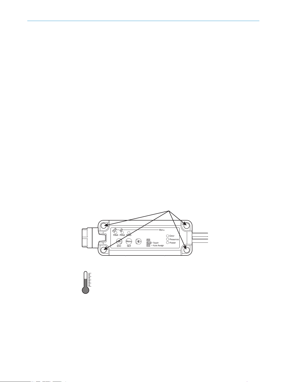
4 Mounting
<0,7 Nm
–25°C ... +50 °C
–13°F ... +122 °F
4.1 Scope of delivery
FlexChain host with 2x bus terminator
•
Quickstart
•
Safety notes
•
The FlexChain guests and mounting accessories are not included in the scope of deliv‐
ery and need to be purchased separately.
4.2 Installation requirements
Typical space requirement for the device, see type-specific dimensional drawing,
•
see "Technical data", page 35.
Comply with technical data, such as the permitted ambient conditions for opera‐
•
tion of the device (e.g., temperature range, EMC interference emissions, ground
potential).
To prevent condensation, avoid exposing the device to rapid changes in tempera‐
•
ture.
Protect the device from direct sunlight.
•
Protect the device from external light sources.
•
The device must only be mounted using the pairs of mounting threads/fixing holes
•
provided for this purpose.
Shock and vibration-free mounting.
•
MOUNTING 4
4.3 Installing the system
Installing the FlexChain host
Figure 2: FlexChain host - installation
Figure 3: FlexChain host - installation
Installing the FlexChain guest
The procedure for installing a guest can vary significantly depending on the device fam‐
ily or device type. See the instructions supplied with the device for installation instruc‐
tions.
8023047/2018-11-15 | SICK O P ER A TI N G I NS T RU C TI O NS | FlexChain
Subject to change without notice
11
Page 12

5 ELECTRICAL INSTALLATION
5 Electrical installation
5.1 Notes on electrical installation
NOTICE
Equipment damage due to incorrect supply voltage!
An incorrect supply voltage may result in damage to the equipment.
■
Only operate the device with safety/protective extra-low voltage (SELV/PELV).
■
The sensor is a device of protection class III.
NOTICE
Equipment damage due to incorrect supply voltage!
An incorrect supply voltage may result in damage to the equipment.
Only operate the device with an LPS (limited power source) in accordance with IEC
•
60950-1 or an NEC Class 2 power supply unit.
NOTICE
Equipment damage or unpredictable operation due to working with live parts!
Working with live parts may result in unpredictable operation.
■
Only carry out wiring work when the power is off.
■
Only connect and disconnect electrical connections when the power is off.
NOTICE
Device damage due to incorrect connection!
Incorrect connection may result in damage to the FlexChain system or peripheral
devices.
■
If connection cables are required, use twisted pair connection cables.
■
Standard M8 4-pin connection cables can also be used in many applications.
■
The electrical installation must only be performed by electrically qualified person‐
nel.
■
Standard safety requirements must be observed when working on electrical sys‐
tems!
■
Only switch on the supply voltage for the device when the connection tasks have
been completed and the wiring has been thoroughly checked.
■
When using extension cables with open ends, ensure that bare wire ends do not
come into contact with each other (risk of short-circuit when supply voltage is
switched on!). Wires must be appropriately insulated from each other.
■
Wire cross-sections in the supply cable from the user’s power system must be
selected in accordance with the applicable standards.
■
Only operate the device with an LPS (limited power source) in accordance with IEC
60950-1 or an NEC Class 2 power supply unit.
■
All circuits connected to the device must be designed as SELV/PELV circuits.
■
Operation in short-circuit protected network at max. 8 A.
12
O PE R AT I NG IN S TR U CT I ON S | FlexChain 8023047/2018-11-15 | SICK
Subject to change without notice
Page 13

NOTE
Layout of data cables
■
Use shielded data cables with twisted-pair wires.
■
Implement the shielding design correctly and completely.
■
To avoid interference, e.g., from switching power supplies, motors, clocked drives,
and contactors, always use cables and layouts that are suitable for EMC.
■
Do not lay cables over long distances in parallel with voltage supply cables and
motor cables in cable channels.
The IP enclosure rating for the device is only achieved under the following conditions:
■
The cables plugged into the connections are screwed tight.
If these instructions are not complied with, the IP enclosure rating for the device is not
guaranteed!
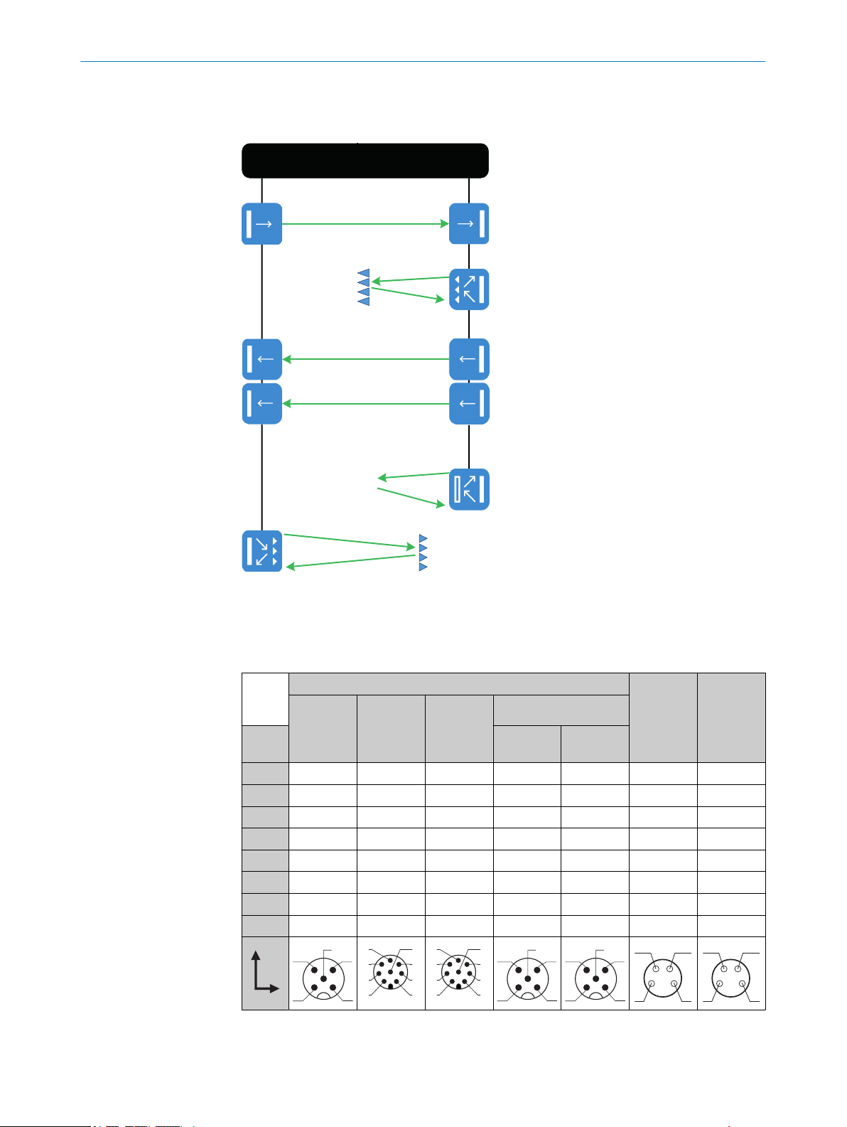
5.2 Schematic arrangement
The first guest is connected to the host using the pigtail. It can be connected to either
port A or port B. Up to 30 sensors in total can be connected per port.
All guests have an M8 4-pin male connector and an M8 4-pin female connector (pig‐
tail). The pigtail can always be connected to the male connector of the next guest.
The bus terminator must be connected at the end of the system. This is included in the
scope of delivery of the FlexChain host.
With regard to the arrangement of the guests on Port A and Port B, there is only one
restriction for sender and receiver sensors: the sender and the associated receiver
must not be connected to the same port.
If the pigtail cable is insufficiently long, it can be extended using an M8 4-pin cable.
Ensure that the total cable length of the system does not exceed 40 m when doing so.
ELECTRICAL INSTALLATION 5
8023047/2018-11-15 | SICK O P ER A TI N G I NS T RU C TI O NS | FlexChain
Subject to change without notice
13
Page 14
FlexChain Host
Port A
Port B
1
2
5
4 3
1
3
5
4
7
6
8
2
1
3
5
4
7
6
8
2
1
2
5
4 3
1
2
5
4 3
4
3
1
2
4
3
1
2
ELECTRICAL INSTALLATION
5
5.3 Pin assignment of the connections
Overview of pin assignment - FlexChain host
Table 1: DC
Flex‐
Chain
host
Standard
IO-Link
Advanced
IO-Link
1 + (L+) + (L+) + (L+) + (L+) n.c. +5 V CANH
2 Q2 / IN1 Q2 / IN1 Q2 / IN1 Q2 / IN1 n.c. D- CANL
3 M M M M GND D+ 12 Vout
4 Q1 / C Q1 / C Q1 / C Q1 / C CAN1_H GND GND
5 Q3 / In2 Q3 / IN2 n.c. n.c. CAN1_L - -
6 - Q4 / IN3 n.c. - - -
7 - Q5 / IN4 RS485_A - - -
8 - Q6 / IN5 RS485_B - - -
PLC
RS485
CANopen
System/Q
CAN con‐
nector
USB
Port A/
port B
The system can be configured via the USB interface and SOPAS. An M8->USB-A adapter
cable is required to connect the system to a computer (part number: 6051163).
14
O PE R AT I NG IN S TR U CT I ON S | FlexChain 8023047/2018-11-15 | SICK
Subject to change without notice
Page 15

Overview of pin assignment - FlexChain guests
2
1
4
3
2
1
4
3
2
1
4
3
Table 2: DC
GL6-C
1 + (L+)
2 M
3 CAN-High
4 CAN-Low
Table 3: DC
GSE6-C
1 CAN high
2 CAN low
3 12 V
4 GND
ELECTRICAL INSTALLATION 5
out
Table 4: DC
GTB6-C
1 + (L+)
2 M
3 CAN high
4 CAN low
5.4 Connecting the supply voltage
NOTICE
Risk of damage to the device!
The device can become damaged if it is connected to a voltage supply that is already
switched on.
Only connect the device when the supply cable is de-energized.
•
The device must be connected to a power supply unit with the following properties:
24 V voltage supply ± 20% or DC 19.2 V – 28.8 V (SELV/PELV as per currently
•
applicable standards)
The current consumption depends on the number of connected sensors and is
•
typically 100 mA and maximum 850 mA.
To ensure protection against short-circuits/overload in the customer’s supply cables,
the wire cross-sections used must be appropriately selected and protected.
8023047/2018-11-15 | SICK O P ER A TI N G I NS T RU C TI O NS | FlexChain
Subject to change without notice
15
Page 16

5 ELECTRICAL INSTALLATION
5.5 Digital interfaces
The digital interfaces can be configured via SOPAS, or directly via the serial interfaces
(except RS-485). Apart from PIN4, every digital interface can be configured as a digital
input or digital output.
Furthermore, every digital interface can be assigned a number of different functions
(see Configuration via SOPAS).
The signal state (HIGH/LOW) is shown on the FlexChain host display.
16
O PE R AT I NG IN S TR U CT I ON S | FlexChain 8023047/2018-11-15 | SICK
Subject to change without notice
Page 17

6 Commissioning
Menu
>2s
Menu
Menu
Menu
>2s
6.1 Simplified illustration
Perform any other operation with the SOPAS ET user interface. Download at:
www.sick.com
1. Connect sensors to port A and port B.
2. Connect the power supply. The Power LED lights up green.
3. Perform AutoAssign
AutoAssign detects all connected guests. Automated assignment of guest posi‐
tions and zones, e.g. A1 ... AN, B1 ... BM.
COMMISSIONING
6
4. Perform teach-in
Perform teach-in for sensors. Set sensors with potentiometer directly on the sen‐
sor.
8023047/2018-11-15 | SICK O P ER A TI N G I NS T RU C TI O NS | FlexChain
Subject to change without notice
17
Page 18

Menu
Menu
Menu
>2s
>2s
COMMISSIONING
6
5. Baud rate (RS485, CANopen)
Set baud rate for FlexChain host variant with RS485 and CANopen.
6. NodeID (CANopen)
Set NodeID for FlexChain host with CANopen. A single value or several values can
be set or deleted (bit display).
18
O PE R AT I NG IN S TR U CT I ON S | FlexChain 8023047/2018-11-15 | SICK
Subject to change without notice
Page 19

Menu
Menu
Menu
>2s
>2s
COMMISSIONING 6
8023047/2018-11-15 | SICK O P ER A TI N G I NS T RU C TI O NS | FlexChain
Subject to change without notice
19
Page 20

OPERATION
7
7 Operation
7.1 Configuration via SOPAS ET
To configure the system via SOPAS you will need the SOPAS software, the SOPAS Device
Description (SDD), and a USB connection.
NOTE
The USB interface is intended only for configuring the device and must be unplugged
during operation.
The SOPAS screen for FlexChain is divided into a number of tabs (orange). Every tab
provides a specific set of parameterization functions. You can easily jump back and for‐
ward between the tabs.
7.1.1 Home
20
The Home tab does not contain any settings. The purpose of this tab is to provide you
with information and status details for the connected FlexChain system.
The Home tab is divided into three areas.
The area on the left (red) shows information about the current status of the system.
This includes, for example, the status of the switching input and switching output pins,
the system status, the teach-in status, etc.
The middle area (green) provides a live display of the channel status. This area shows
which channel is blocked or not blocked by an object. If there is something wrong with a
sensor, this is also indicated directly in this display.
The area on the right (blue) lists the technical values and settings. Details such as the
response time and the number of connected guests are shown here. Furthermore, you
can select a specific guest in the green area by clicking on it. The information for the
selected guest then appears in the “Guest Information” area on the right hand side.
O PE R AT I NG IN S TR U CT I ON S | FlexChain 8023047/2018-11-15 | SICK
Subject to change without notice
Page 21

7.1.2 Teach & Positioning
The Teach & Positioning tab can be used to teach in the switching threshold of individ‐
ual guests or all guests at once. The guest position can also be set automatically (auto‐
mated position assignment) or changed manually.
OPERATION 7
Automated positioning
The “Automated position assignment” method is used to automatically assigned a posi‐
tion to every guest in the FlexChain system. Positions are assigned based on the follow‐
ing rules:
1 The first position is the first guest connected to port A. Further positions are then
assigned in increasing numerical order for the guests hanging off port A.
2 All guests on port B are then numbered according to the same principle as in step
1.
3 Sender/receiver sensors are always jointly assigned a position. The receiver
serves as the reference during positioning.
The transmitted process data word also varies according to the position of the guest.
For example, the first channel of the guest at position 1 is represented by the first bit in
the process data word. This means that the sequence within the process data word
depends directly on the guest positions.
Note when changing the number of guests: if a guest is removed or a new guest con‐
nected, this guest is not taken into consideration when using the “Automated position
assignment” positioning method. You need to either use the “Confirm chain change”
method beforehand, or perform the “Auto assign” method (see below).
Manual positioning
The position of each guest can be individually configured via the serial interface and/or
via SOPAS. This option was implemented because the automated positioning may not
always represent the actual physical position in the application. The manual positioning
option was therefore created for simpler organization or easier interpretation of the
process data word.
A comparison of the addressing, the automated positioning, and the desired positioning
is shown in Figure 3.
8023047/2018-11-15 | SICK O P ER A TI N G I NS T RU C TI O NS | FlexChain
Subject to change without notice
21
Page 22

7 OPERATION
Using SOPAS, the position of a guest can be easily changed via drag & drop (see Figure
4). Note that the sequence number in the process data word also changes depending
on the positioning.
22
To ensure the correct guest has been selected, detailed information about the selected
guest is shown on the right hand side. There is also a “Find Me” function for easily
locating a guest. After selecting a specific guest and pressing the Find Me button, the
LEDs on the selected guest light up.
NOTE
1 Find Me can also be activated during process data operation (PD = valid). Note,
however, that this will have a periodic effect (500 ms) on the cycle time.
2 The Find Me function is automatically deactivated by the device for certain com‐
mands/configurations (Factory reset, Teach-in, Confirm chain change, Automated
assignment, Automated position assignment, Change position, or Teach-in posi‐
tion).
O PE R AT I NG IN S TR U CT I ON S | FlexChain 8023047/2018-11-15 | SICK
Subject to change without notice
Page 23

7.1.2.1 Confirm chain change
The total number of connected guests and their respective threshold values are stored
in the host. If the number of guests changes at a later time, a warning message is dis‐
played. Confirm chain change is used to confirm the new total guest count and store it
in the host. The warning message is no longer displayed.
OPERATION
7
7.1.2.2 Automated assignment
Automated assignment performs the three methods “Confirm chain change”, “Auto‐
mated position assignment”, and “Automated zone assignment” (see also the Zone
tab).
7.1.2.3 Teach
There are a number of different teach modes available.
– Teach all guests
Sets the threshold value for all centralized and teachable guests
– Teach guest
Sets the threshold value for the selected guest.
– Auto teach-in
If the option is selected, teach-in is carried out automatically whenever the voltage
supply is interrupted. There must have been no changes to the sensors, otherwise
an AutoAssign must be performed.
There are sensors where the threshold value can only be set manually directly on the
sensor. A teach in via the host is not possible in this case.
The teach-in status should be queried after a teach-in. This returns a response for each
individual slave position.
IOLink307SlaveTeachInStatus can have the following values:
– Teach-in Necessary (0)
is set if the slave at the relevant position has been replaced (serial number has
changed), provided the slave is actually teachable, a teach-in has not already been
carried out at that position, an Automatic assignment, Confirm chain change, Fac‐
tory reset or DataStorage download has been performed.
– OK (1) (the last teach-in was successful)
– Fail (2) (the last teach-in failed, e.g., poor alignment)
This is an immediate teach-in response. It is also retained after a restart, and does
not become a “Teach-in Necessary”.
8023047/2018-11-15 | SICK O P ER A TI N G I NS T RU C TI O NS | FlexChain
Subject to change without notice
23
Page 24

7 OPERATION
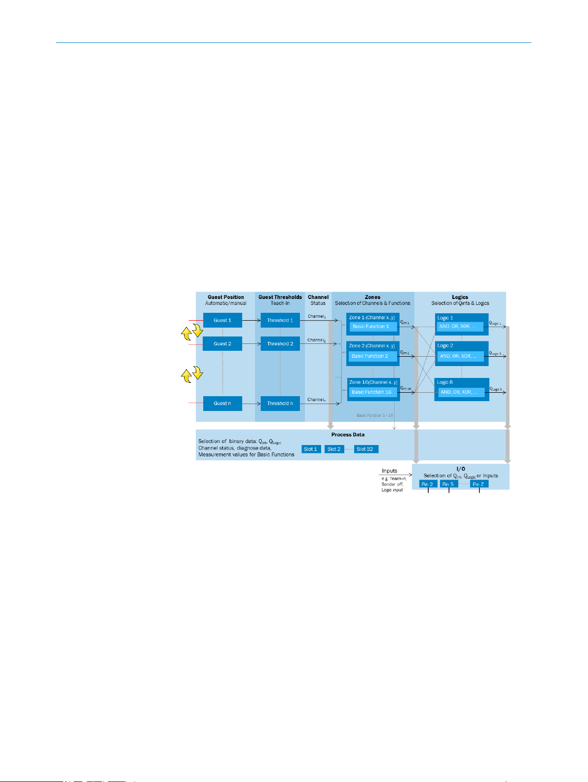
7.1.3 Zones
– Local Adjustment at Device (optional) (3) (e.g., GTB with local pot)
– Not Available (4) (Slave does not have a teach-in function, for example a sender, or
is completely masked (user mask))
7.1.3.1 Zone definition
The Zones tab can be used to define multiple areas or zones. Up to 16 zones can be
defined.
The zones are displayed, on the one hand, in a table on the right hand side. You can
configure the zones there. The zones are also shown in the system schematic (on the
left).
Specific measurement functions can be defined within each zone. The result is passed
on as an internal output state, which in turn can be used as input for further functions,
or directly outputted via an output. The measurement results of a zone can also be out‐
putted via the serial interface (see also PROCESS DATA).
Automated zone assignment
The “Automated zone assignment” function is performed by “Automated zone assign‐
ment” or “Auto assignment”. When performed, every guest in the zone is assign the
NCB>=1 (number of channels blocked greater than or equal to 1) function. NCB>=1
means that if at least one channel in the zone is blocked, the internal output state is
set to “High”.
The exception to this is zone 1. It is initially defined as the first channel to the last chan‐
nel. If more than 16 guests are connected and the “Automated zone assignment” func‐
tion is performed, the last zone is assigned from Guest16 to Guestmax.
Manual zone assignment
You can individually select each zone in the right hand area of the screen, and config‐
ure the zone in the bottom area. The “Status” column shows whether the internal out‐
put state Qint is active or not.
24
Figure 4: Overview of the settings for each zone
O PE R AT I NG IN S TR U CT I ON S | FlexChain 8023047/2018-11-15 | SICK
Subject to change without notice
Page 25

OPERATION
Figure 5: Zone configuration options
7
The zone range can be set in the parameterization area (e.g., from Channel 3 – Channel
6). It is also possible to define different measurement functions within each zone.
These include:
8023047/2018-11-15 | SICK O P ER A TI N G I NS T RU C TI O NS | FlexChain
Subject to change without notice
25
Page 26
OPERATION
7
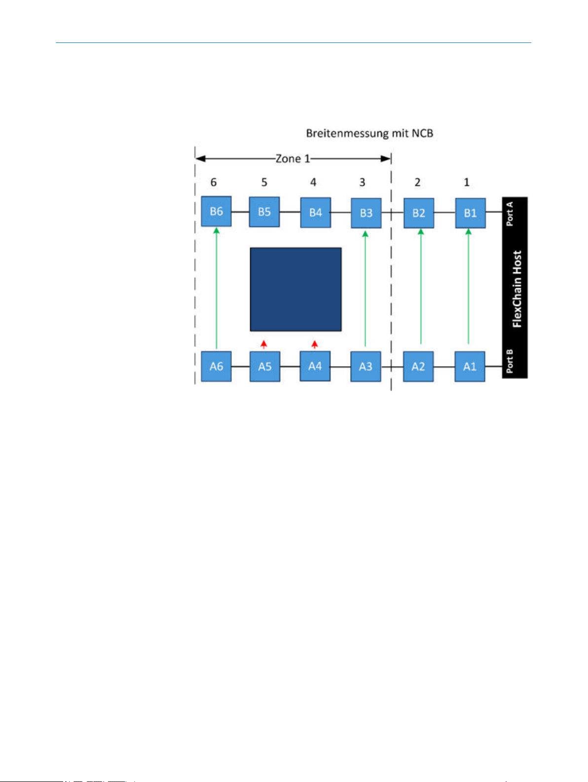
1 NCB: for object detection or width classification
Example 1: NCB>=1 for object detection (Qint active if at least 1 channel is
blocked)
Example 2 (see graphic): NCB=2 for width classification (Qint active if exactly 2
channels in a zone are blocked)
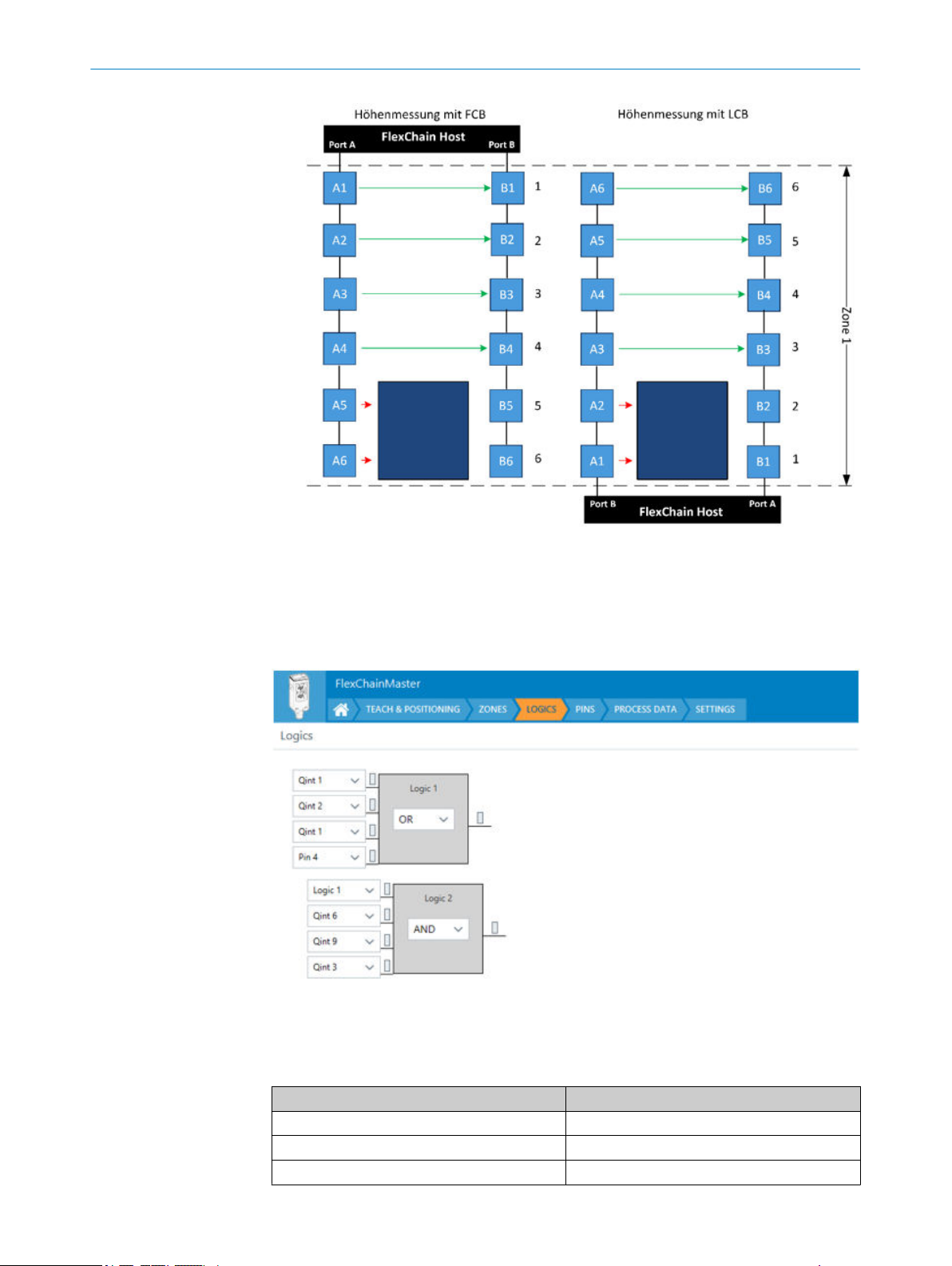
2 LCB/FCB: for height or position determination
FCB: first channel blocked. This is the blocked channel in the zone that is located
closed to the host.
LCB: last channel blocked. This is the blocked channel in the zone that is located
furthest from the host.
Example: Zone1 extends from channel 1 to 6
LCB >=2: if the last channel blocked in the zone is channel 2 or higher, the internal
output state Qint1 is activated. (right side of graphic)
FCB >=2: if the first channel blocked in the zone is channel 5 or lower, the internal
output state Qint1 is activated. (left side of graphic).
26
O PE R AT I NG IN S TR U CT I ON S | FlexChain 8023047/2018-11-15 | SICK
Subject to change without notice
Page 27
OPERATION 7
7.1.4 Logics
The Logic tab can be used to further process the individual Qint internal output states
or external signals using logic functions (AND, OR,…). A total of 8 logics are available,
whereby Logixn-x (x>=1 and x<n) can also be used as an input signal for Logicn. The
logic state can be outputted via the switching output or via the serial interface.
Figure 6: Logics tab with two logics
If all logic inputs of a gate are “Not Used”, the result will differ depending on the logic
function selected. This fact can also be used to produce a constant 0 or 1.
Logic function Result
AND 1
OR 0
XOR 0
8023047/2018-11-15 | SICK O P ER A TI N G I NS T RU C TI O NS | FlexChain
Subject to change without notice
27
Page 28

7 OPERATION
Logic function Result
NAND 0
NOR 1
XNOR 1
An input that is “Not Used” is not actually removed but instead replaced with a value
that does not change the result, i.e. 1 for AND and NAND, otherwise 0.
The XOR function is not generally defined for more than two inputs.
The following definitions were selected for the FlexChain implementation:
Eingänge Ausgänge
IN1 IN2 NXOR IN3 XOR NXOR
0 0 0 0 1
0 0 0 1 0
0 0 1 0 0
0 0 1 1 1
0 1 0 0 0
0 1 0 1 1
0 1 1 0 1
0 1 1 1 0
1 0 0 0 0
1 0 0 1 1
1 0 1 0 1
1 0 1 1 0
1 1 0 0 1
1 1 0 1 0
1 1 1 0 0
1 1 1 1 1
7.1.5 PINS
28
O PE R AT I NG IN S TR U CT I ON S | FlexChain 8023047/2018-11-15 | SICK
The PINS tab can be used to configure which information is assigned to, or should be
outputted for a pin.
Possible output signals
1 Qint
Outputs the Qint statuses of the zones
2 Logic
Outputs the configured logics
3 Masked System Status
A system status bit. You can configure when, and for which warnings and error
messages this signal should be high.
Possible input signals
1 Teach-In Trigger
For performing an external teach-in.
2 Logic In
The input signal can be used for the logics.
3 Blocked Channel Hold
While this signal is high, the process data are stored in the host. When the signal
becomes low, the highest value (e.g., largest measured height) is transmitted.
Subject to change without notice
Page 29

7.1.6 Process data
OPERATION 7
4 RS-485 Trigger
Sends data as soon as a signal is high.
5 Sender Off
Test function for simulating object detection: The sender LEDs can be deactivated
via the input. This can be used to test whether the associated receiver LED
responds.
The FlexChain process data word has a length of 32 bytes. Each of these bytes can be
individually populated with the desired data.
Figure 7: Overview of the Process Data tab
Loading process data via profiles
A number of pre-defined process data profiles are available that can be selected to
populate the process data word.
Figure 8: Loading process data via a profile
Manually customizing the process data
Each individual byte of the process data can be customized. After clicking on a byte, a
drop-down list of information that can be assigned to the byte is displayed. The length
of each “information block” is limited to one byte (8 bits). A single byte can therefore be
used, for example, to transmit 8 channel states.
8023047/2018-11-15 | SICK O P ER A TI N G I NS T RU C TI O NS | FlexChain
Subject to change without notice
29
Page 30

7 OPERATION
The available information is shown in figure 14. NCB, FCB and LCB are the actual mea‐
sured values. For example, NCB transmits how many channels in the zone are blocked.
30
O PE R AT I NG IN S TR U CT I ON S | FlexChain 8023047/2018-11-15 | SICK
Subject to change without notice
Page 31

7.1.7 Settings
OPERATION
7
Figure 9: Settings tab
The following settings can be configured in the Settings tab:
1 Local interface lock: Locks the buttons on the display
2 Crosstalk Offset Time: If two identical FlexChain systems are operated in close
proximity to one another, there is a possibility of mutual interference. The
Crosstalk Offset Time changes the cycle time of the FlexChain system. The two sys‐
tems can then no longer interfere with one another due to the different cycle time
and the standard 2-bit processing.
3 “Notification handling” can be used to activate or deactivate events. Various
events such as overtemperature, overvoltage, etc. can be selected. PDinvalid
means invalid process data.
4 Test functions: Deactivates the sender LED. This is used to check whether the
receiver is responding.
5 Factory reset: Restores all settings to the factory defaults. If there are guests con‐
nected to the system, these need to be reassigned using “Automated assignment”,
and then taught in again using “Teach all devices”.
6 Blanked channels: The “blank all currently made/blocked channels” functions can
be used to hide all free or currently blocked beams. This function is useful if there
is a static object in the light path (e.g., light grid). The channels can also be individ‐
ually hidden using Ctrl-left mouse button. Channels that are hidden are no longer
included in the process data.
8023047/2018-11-15 | SICK O P ER A TI N G I NS T RU C TI O NS | FlexChain
Subject to change without notice
31
Page 32

8 TROUBLESHOOTING
8 Troubleshooting
LED indicator/fault pattern Cause Measures
red error LED lights up Short-circuit Check connections
Yellow TCH LED flashes
yellow presence LED
flashes
Yellow LED AA flashes
Red LED Error flashes
Teach-in faulty Check the alignment of all
guests
Perform TeachIn
Position or zones inconsistent. Check connection of all guests
and alignment of the sensors
Perform AutoAssign
Perform TeachIn
32
O PE R AT I NG IN S TR U CT I ON S | FlexChain 8023047/2018-11-15 | SICK
Subject to change without notice
Page 33

9 Maintenance
9.1 Maintenance
During operation, the device works maintenance-free.
Depending on the assignment location, the following preventive maintenance tasks
may be required for the device at regular intervals:
Table 5: Maintenance schedule
Maintenance work Interval Implementation
Clean housing and front screen
Check screw connections and plug
connectors
MAINTENANCE 9
Cleaning interval depends on ambi‐
ent conditions and climate
Every 6 months Specialist
Specialist
8023047/2018-11-15 | SICK O P ER A TI N G I NS T RU C TI O NS | FlexChain
Subject to change without notice
33
Page 34

10 DECOMMISSIONING
10 Decommissioning
10.1 Disassembly and disposal
Disassembling the device
1. Switch off the supply voltage to the device.
2. Detach all connecting cables from the device.
3. If the device is being replaced, mark its position and alignment on the bracket or
surroundings.
4. Detach the device from the bracket.
Disposing of the device
Any device which can no longer be used must be disposed of in an environmentally
friendly manner in accordance with the applicable country-specific waste disposal regu‐
lations. As it is categorized as electronic waste, the device must never be disposed of
with household waste!
10.2 Returning devices
Do not dispatch devices to the SICK Service department without consultation.
b
NOTE
To enable efficient processing and allow us to determine the cause quickly, please
include the following when making a return:
■
Details of the contact person
■
Description of the application
■
Description of the fault that occurred
34
O PE R AT I NG IN S TR U CT I ON S | FlexChain 8023047/2018-11-15 | SICK
Subject to change without notice
Page 35

11 Technical data
11.1 Host performance
Attribute Value
Number of connectable guests max. 60 (max. 30 / port)
Number of Channels max. 255
Max. total cable length 40 m/port
Max. sensor to sensor or sensor to host cable length 30 m
1
For > 25 guests/port: Total length plus additional extension cables ≤ 10 m/port
11.2 Host interfaces
1
TECHNICAL DATA 11
Attribute IO-Link 5Pin IO-Link
CAN CANopen RS485
8Pin
No. of IOs (push-pull switching mode) 1xQ 2xI/O 1xQ 5xI/O 1xQ 1xI/O - 1xQ 1xI/O
Serial process data interface IO-Link IO-Link IO-Link
CANopen
Parameterization interface Membrane keyboard
IO-Link
USB
Membrane
keyboard
IO-Link
USB
Membrane
keyboard
IO-Link
USB
- IO-Link
RS485
- Membrane
keyboard
IO-Link
USB
CANopen
Data transmission rate COM3 (230.4 kbit/s) - 50 kbit/s,
125
kbit/s,
250
kbit/s,
500
kbit/s,
1Mbit/s
9.6
kbit/s,
38.4
kbit/s,
11.52
kbit/s,
230.4
kbit/s,
460.8
kbit/s
Connection type (control)
Pigtail length 0.5 m (except CANopen)
PIN M12, 5-pin, male M12, 8-
pin, male
M12, 8pin, male
M12, 5pin, male
M12, 8pin, male
Pigtail
length
0.3 m
1 L+ (BN) L+ (BN) L+ (BN) n.c. (BN) L+ (BN)
2 Q2 / IN1 (WH) Q2 / IN1
(WH)
Q2 / IN1
(WH)
n.c. (WH) Q2 / IN1
(WH)
3 M (BU) M (BU) M (BU) GND (BU) M (BU)
4 Q1 / C (BK) Q1 / C
(BK)
5 Q3 / IN2 (GY) Q3 / IN2
(GY)
6 - Q4 / IN3
Q1 / C
(BK)
n.c. (GY) CAN1_L
CAN1_H
(VT)
Q1 / C
(BK)
n.c. (GY)
(OG)
- - n.c. (PK)
(PK)
7 - Q5 / IN4
(VT)
8 - Q6 / IN5
(OG)
- - RS485_A
(VT)
- - RS485_B
(OG)
8023047/2018-11-15 | SICK O P ER A TI N G I NS T RU C TI O NS | FlexChain
Subject to change without notice
35
Page 36

11 TECHNICAL DATA
Attribute IO-Link 5Pin IO-Link
CAN CANopen RS485
8Pin
Connection type (USB) PIN Pigtail length 0.3 m M8, 4-pin, female
1 +5 V USB Supply (BN)
2 USB Data - (WH)
3 USB Data + (BU)
5 USB GND (BK)
Connection type (guests) Port A and port B
Pigtail length 1.5 m each
Pigtail M8, 4-pin, female
NOTICE
Do not connect a USB otherwise the USB port of the PC could be dam‐
aged.
1
For > 25 guests/port: Total length plus additional extension cables ≤ 10 m/port
11.3 Host software features
Attribute Value
Host software features Sensor parameterization
Zone definition
Measurement functions, logic gates
Interface parameterization
Service data
11.4 System response time
Attribute Value
Scan time T
Minimum presence time 2x T
Response time 3x T
scan
T
FC_GTB6
T
FC_GL6
T
FC_GSE6
= 185 µs
= 185 µs
= 210 µs
scan
+500 µs
scan
11.5 Mechanics/electronics/host
Attribute Value
Supply voltage V
S
Maximum current consumption (at maximum number of
guests)
Output current max. 100 mA
Logic level Active 15 V to 30 V
Capacitive output load max. 100 nF
24 V ±20%
600 mA @ 24 V
Inactive 0 V to 5 V
36
O PE R AT I NG IN S TR U CT I ON S | FlexChain 8023047/2018-11-15 | SICK
Subject to change without notice
Page 37

TECHNICAL DATA 11
Attribute Value
Inductive output load max. 1 H
Required overcurrent protection Operation in short-circuit protected network max. 8 A
Dimensions in mm 118 x 35 x 25 (without cables)
Housing material Plastic, ABS
Enclosure rating IP65 / IP67
Electrical protection class III
Circuit protection Reverse polarity protected UV connections
Output Q, short-circuit protected
Interference pulse suppression
Storage temperature -25° C to 70° C
Operating temperature Guests -25° C to 55° C
Host -25° C - 50° C
Vibration/shock resistance of host Single shock:
30 g, 11 ms, 6 each axis
DIN EN 60068-2-27
Continuous shock:
25 g, 6 ms, 1,000 each axis
DIN EN 60068-2-27
Vibration:
10 grms 20 Hz to 2,000 Hz, 2 h each axis
IEC 60068-2-64
Vibration/shock resistance of G6 guest Single shock:
30 g, 11 ms, 6 each axis
DIN EN 60068-2-27
Continuous shock:
25 g, 6 ms, 1,000 each axis
DIN EN 60068-2-27
Vibration:
10 grms 20 Hz to 2,000 Hz, 2 h each axis
IEC 60068-2-64
Vibration/shock resistance of SLG-2 guest Shock:
10 g 16 ms
DIN EN 60068-2-27
Vibration: 5 g 10 Hz to 55 Hz
IEC 60068-2-64
Electromagnetic compatibility 61000-6-2 immunity / 61000-6-3 emission
MTBF > 50,000 h
Weight of host 5-pin IO-Link: 154 g
8-pin O-Link, RS485: 161 g
CANopen: 170 g
Weight of G6 guests 23 g (GTB, GL, GS, GE)
Initialization time < 1 s
Synchronization of port A/port B Cable
11.6 Technical data guests
11.6.1 General data GL6-C
Attribute Value
Sensing range RW max. (with PL80A reflector) 0,03 ... 7,2 m
Light spot diameter/distance 8 mm / 350 mm
8023047/2018-11-15 | SICK O P ER A TI N G I NS T RU C TI O NS | FlexChain
Subject to change without notice
37
Page 38

500 (19.69) 109.4 (4.31) 1,500 (59.06)
300 (11.81) 15.9 (0.63)
82.6 (3.25) 5.5 (0.22)
20.1 (0.79)
5.5 (0.22)
24 (0.94)
35 (1.38)
4
3
1
2
5
6
11 TECHNICAL DATA
Attribute Value
Enclosure rating IP67
Protection class III
Circuit protection A, B, D
Ambient operating temperature -25° C - 55°C
1
A = UV-connections reverse polarity protected
B = inputs and output reverse-polarity protected
C = Interference suppression
D = outputs overcurrent and short-circuit protected
11.6.2 General data GSE6-C
Attribute Value
Sensing range RW max. (with PL80A reflector) 0 ... 15 m
Light spot diameter/distance 375 mm / 12 m
Enclosure rating IP67
Protection class III
Circuit protection A, B, D
Ambient operating temperature -25° C - 55°C
1
A = UV-connections reverse polarity protected
B = inputs and output reverse-polarity protected
C = Interference suppression
D = outputs overcurrent and short-circuit protected
1
1
11.6.3 General data GTB6-C
Attribute Value
Sensind range (with 90 % remission) 5 ... 250 mm
Light spot diameter/distance 6 mm / 100 mm
Enclosure rating IP67
Protection class III
Circuit protection A, B, D
1
Ambient operating temperature -25° C - 55°C
1
A = UV-connections reverse polarity protected
B = inputs and output reverse-polarity protected
C = Interference suppression
D = outputs overcurrent and short-circuit protected
11.7 Dimensional drawings
Figure 10: Dimensional drawing - FlexChain host
Port-A, pigtail M8, 4-pin, female
1
38
O PE R AT I NG IN S TR U CT I ON S | FlexChain 8023047/2018-11-15 | SICK
Subject to change without notice
Page 39

Port B, pigtail M8, 4-pin, female
21 (0.83)
0.5
(0.02)
3 (0.12)
12 (0.47)
18.3 (0.72)
9.7 (0.38)
0.5
(0.02)
25.4 (1.0)
9.7
(0.38)
7.6
(0.3)
28.5 (1.12)
31.5 (1.24)
11.4
(0.45)
1
2
3
4 5
2
PLC, pigtail M12, 5-pin / 8-pin, male
3
USB, pigtail M8, 4-pin, female
4
Control panel
5
TECHNICAL DATA 11
Figure 11: Dimensional drawing - FlexChain GL6-C
Center of optical axis, sender
1
Center of optical axis, receiver
2
M3 threaded mounting hole
3
LED indicator yellow
4
LED indicator green
5
8023047/2018-11-15 | SICK O P ER A TI N G I NS T RU C TI O NS | FlexChain
Subject to change without notice
39
Page 40

21 (0.83)
0.5
(0.02)
3 (0.12)
12 (0.47)
18.3 (0.72)
9.7 (0.38)
0.5
(0.02)
25.4 (1.0)
17.3 (0.68)
9.7
(0.38)
28.5 (1.12)
31.5 (1.24)
11.4
(0.45)
1
2
3
4 5
21 (0.83)
0.5
(0.02)
3 (0.12)
12 (0.47)
18.3 (0.72)
9.7 (0.38)
0.5
(0.02)
25.4 (1.0)
9.7
(0.38)
7.6
(0.3)
2.8
(0.11)
28.5 (1.12)
31.5 (1.24)
11.4
(0.45)
1
6
2
3
4 5
11 TECHNICAL DATA
Figure 12: Dimensional drawing - FlexChain GSE6-C
Center of optical axis, sender
1
Center of optical axis, sender
2
M3 threaded mounting hole
3
LED indicator green
4
LED indicator yellow
4
Figure 13: Dimensional drawing - FlexChain GTBE6-C
1
2
3
4
Center of optical axis, sender
Center of optical axis, receiver
M3 threaded mounting hole
LED indicator green
40
O PE R AT I NG IN S TR U CT I ON S | FlexChain 8023047/2018-11-15 | SICK
Subject to change without notice
Page 41

LED indicator yellow
5
Potentiometer: adjusting the sensing range
6
11.8 FlexChain host membrane keyboards
Figure 14: FlexChain host membrane keyboard - standard IO-Link
TECHNICAL DATA
11
Figure 15: FlexChain host membrane keyboard - advanced IO-Link
Figure 16: FlexChain host membrane keyboard - RS485 / CANopen
8023047/2018-11-15 | SICK O P ER A TI N G I NS T RU C TI O NS | FlexChain
Subject to change without notice
41
Page 42

12 ACCESSORIES
12 Accessories
NOTE
Accessories can be found on the online product page at:
b
www.sick.com/FlexChain
42
O PE R AT I NG IN S TR U CT I ON S | FlexChain 8023047/2018-11-15 | SICK
Subject to change without notice
Page 43

13 Annex
13.1 EU declaration of conformity and certificates
The EU declaration of conformity and other certificates can be downloaded from the
Internet at:
www.sick.com/FlexChain
b
ANNEX 13
8023047/2018-11-15 | SICK O P ER A TI N G I NS T RU C TI O NS | FlexChain
Subject to change without notice
43
Page 44

Further locations at www.sick.com
Australia
Phone +61 (3) 9457 0600
1800 33 48 02 – tollfree
E-Mail sales@sick.com.au
Austria
Phone +43 (0) 2236 62288-0
E-Mail office@sick.at
Belgium/Luxembourg
Phone +32 (0) 2 466 55 66
E-Mail info@sick.be
Brazil
Phone +55 11 3215-4900
E-Mail comercial@sick.com.br
Canada
Phone +1 905.771.1444
E-Mail cs.canada@sick.com
Czech Republic
Phone +420 2 57 91 18 50
E-Mail sick@sick.cz
Chile
Phone +56 (2) 2274 7430
E-Mail chile@sick.com
China
Phone +86 20 2882 3600
E-Mail info.china@sick.net.cn
Denmark
Phone +45 45 82 64 00
E-Mail sick@sick.dk
Finland
Phone +358-9-25 15 800
E-Mail sick@sick.fi
France
Phone +33 1 64 62 35 00
E-Mail info@sick.fr
Germany
Phone +49 (0) 2 11 53 01
E-Mail info@sick.de
Hong Kong
Phone +852 2153 6300
E-Mail ghk@sick.com.hk
Hungary
Phone +36 1 371 2680
E-Mail ertekesites@sick.hu
India
Phone +91-22-6119 8900
E-Mail info@sick-india.com
Israel
Phone +972-4-6881000
E-Mail info@sick-sensors.com
Italy
Phone +39 02 27 43 41
E-Mail info@sick.it
Japan
Phone +81 3 5309 2112
E-Mail support@sick.jp
Malaysia
Phone +603-8080 7425
E-Mail enquiry.my@sick.com
Mexico
Phone +52 (472) 748 9451
E-Mail mario.garcia@sick.com
Netherlands
Phone +31 (0) 30 229 25 44
E-Mail info@sick.nl
New Zealand
Phone +64 9 415 0459
0800 222 278 – tollfree
E-Mail sales@sick.co.nz
Norway
Phone +47 67 81 50 00
E-Mail sick@sick.no
Poland
Phone +48 22 539 41 00
E-Mail info@sick.pl
Romania
Phone +40 356-17 11 20
E-Mail office@sick.ro
Russia
Phone +7 495 283 09 90
E-Mail info@sick.ru
Singapore
Phone +65 6744 3732
E-Mail sales.gsg@sick.com
Slovakia
Phone +421 482 901 201
E-Mail mail@sick-sk.sk
Slovenia
Phone +386 591 78849
E-Mail office@sick.si
South Africa
Phone +27 (0)11 472 3733
E-Mail info@sickautomation.co.za
South Korea
Phone +82 2 786 6321
E-Mail info@sickkorea.net
Spain
Phone +34 93 480 31 00
E-Mail info@sick.es
Sweden
Phone +46 10 110 10 00
E-Mail info@sick.se
Switzerland
Phone +41 41 619 29 39
E-Mail contact@sick.ch
Taiwan
Phone +886-2-2375-6288
E-Mail sales@sick.com.tw
Thailand
Phone +66 2 645 0009
E-Mail marcom.th@sick.com
Turkey
Phone +90 (216) 528 50 00
E-Mail info@sick.com.tr
United Arab Emirates
Phone +971 (0) 4 88 65 878
E-Mail info@sick.ae
United Kingdom
Phone +44 (0)17278 31121
E-Mail info@sick.co.uk
USA
Phone +1 800.325.7425
E-Mail info@sick.com
Vietnam
Phone +65 6744 3732
E-Mail sales.gsg@sick.com
8023047/2018-11-15/en
SICK AG | Waldkirch | Germany | www.sick.com
 Loading...