

Page 1

BEDIENUNGSANLEITUNG /OPERATING INSTRUCTIONS
FFU
Durchussmessgerät
Flow meter
D
EN
Page 2

D
Betriebsanleitung FFU
Inhalt
1 Funktionsprinzip ..........................................................................................................3
2 Sicherheitshinweise ..................................................................................................... 3
3 Einsatzbereiche ..........................................................................................................3
4 Inbetriebnahme ...........................................................................................................4
5 Bedienung .................................................................................................................... 9
6 Werkseinstellung ........................................................................................................16
7 Maßzeichnung ............................................................................................................17
8 Technische Daten .......................................................................................................20
9 Zubehör ....................................................................................................................... 27
10 Rücksendung ............................................................................................................ 28
11 Entsorgung ................................................................................................................28
Contents
1 Principle of operation ................................................................................................. 29
2 Safety notes ................................................................................................................29
3 Applications ................................................................................................................29
4 Commissioning ...........................................................................................................30
5 Operation .....................................................................................................................35
6 Overview of default settings .......................................................................................42
7 Dimensional drawing .................................................................................................. 43
8 Technical data ............................................................................................................. 46
9 Accessories .................................................................................................................53
10 Return........................................................................................................................54
11 Disposal ....................................................................................................................54
12 Notes ......................................................................................................................... 55
Inhalt
2 8013863/10L9 /2018-08-01 © SICK AG • Fluidsensorik • Deutschland • Alle Rechte vorbehalten
Page 3

D
FFU Betriebsanleitung
1 Funktionsprinzip
Gegen die Strömung zu schwimmen benötigt mehr Kraft als mit der Strömung. Auf dieser einfachen
physikalischen Tatsache basiert die Ultraschall-Durchussmessung nach dem Phasen-Differenzverfahren. Zwei gegenüber positionierte Sensoren senden und empfangen wechselweise Ultraschallsignale. Bei stehendem Medium empfangen beide Sensoren die ausgesandten Ultraschallsignale in der
gleichen Phase, d.h. ohne Phasendifferenz. Bei ießendem Medium ergibt sich eine Phasenverschiebung. Sie ist in Stromrichtung gemessen verschieden von der gegen die Stromrichtung gemessenen.
Diese Phasendifferenz ist direkt proportional zur Fließgeschwindigkeit. Aus der Fließgeschwindigkeit
und dem bekannten Durchmesser der Rohrleitung wird das Durchussvolumen ermittelt.
2 Sicherheitshinweise
■
Lesen Sie die Betriebsanleitung vor der Inbetriebnahme.
■
Anschluss, Montage und Einstellung nur durch Fachpersonal.
■
Der FFU ist kein Sicherheitsmodul gemäß EU-Maschinenrichtlinie.
■
Beachten Sie die nationalen Sicherheits- und Unfallverhütungsvorschriften.
■
Reparaturen dürfen nur vom Hersteller durchgeführt werden. Eingriffe und Änderungen am Gerät
sind unzulässig.
■
Verdrahtungsarbeiten, Öffnen und Schließen von elektrischen Verbindungen nur im spannungslosen Zustand durchführen.
■
Unsachgemäßer oder nicht bestimmungsgemäßer Gebrauch können zu Funktionsstörungen in
Ihrer Applikation führen.
■
FFU darf nach der Druckgeräterichtlinie (DGR) Gruppe 2 nur für „ungefährliche Flüssigkeiten“
eingesetzt werden.
1 Funktionsprinzip
3 Einsatzbereiche
Das Durchussmessgerät FFU eignet sich besonders für die Messung von sehr dynamischen Vorgängen in einer Rohrleitung. Gemessen werden Flüssigkeiten. Er ndet seinen Einsatz unter anderem in
■
Chemikalienversorgung für Controlling, Logistik, Überwachung
■
Abfüllungen im Lebensmittelbereich
■
Produktionsmaschinen für Steuerung und Überwachung der Rezepturen
■
Ventilsteuerungen für das Dosieren von Flüssigkeitsvolumina
■
DI-Wasserversorgung
■
Dynamischen Prozessen
Seine Leistungsmerkmale werden durch die folgenden Eigenschaften gekennzeichnet:
■
keine bewegten Teile und damit kein Verschleiß
■
hohe Reproduzierbarkeit
■
einfache Reinigung
■
Manipulationssicherheit
■
kompakte Bauform
■
integrierte Leerrohrerkennung
■
chemische Beständigkeit
■
integrierter Display mit Folientastatur
8013863/10L9 /2018-08-01 © SICK AG • Fluidsensorik • Deutschland • Alle Rechte vorbehalten
3
Page 4

D
Betriebsanleitung FFU
4 Inbetriebnahme
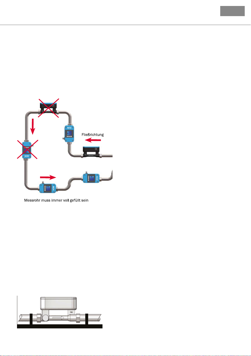
4.1 Einbauhinweise
Auf dem Messkanal des FFU bendet sich ein Pfeil, der die Durchussmessrichtung symbolisiert. Das
Messgerät muss so eingebaut werden, dass das Messrohr in Pfeilrichtung durchossen wird.
OBEN -> Auslauf
UNTEN -> Einlauf
Ideale Einbaulage des FFU
Für eine schnellstmögliche Gasblasenerkennung in der Flüssigkeit ist es wichtig, den Leitungsweg
zwischen Vorlagebehälter und FFU so kurz wie möglich zu halten. Eine fehlerfreie Messung kann nur
gewährleistet werden, wenn die Leitung vollständig gefüllt und sichergestellt ist, dass die Flüssigkeit
nicht ausgast. Abweichend davon kann es bei Dosieranwendungen vorteilhaft sein, den FFU möglichst
nahe am Dosierventil zu platzieren, da Schlauchleitungen ihren Querschnitt je nach Systemdruck
vergrößern. Das kann zu Differenzen führen.
4 Inbetriebnahme
Je nach Flüssigkeit kann durch ausreichend Gegendruck am Auslauf des FFU das Ausgasen der
Flüssigkeit vermieden werden.
Mitgeführte Feststoffpartikel können zu Messfehlern führen.
Beim Einsatz von Pumpen muss der Durchusssensor in Flussrichtung hinter der Pumpe, auf der
Druckseite, eingebaut werden, um sicher zu stellen, dass ein ausreichender Druck vorhanden ist.
Dabei ist die maximale Druckstufe des FFU zu berücksichtigen. Für eine korrekte Volumenstrommessung sind für den FFU gerade und ungestörte Ein- und Auslaufstrecken einzuhalten. Diese betragen
abhängig von der Nennweite mindestens:
DN10 DN15 DN20 DN25
Einlaufstrecke 10 cm 30 cm 40 cm 40 cm
Auslaufstrecke 0 cm 5 cm 10 cm 20 cm
Ebenso ist das maximale Anzugsmoment der Überwurfmuttern für die hydraulischen Anschlüsse zu
beachten. Wir empfehlen die Nutzung der mitgelieferten Dichtungen. Abdichtung mit Teonband kann zu
überhöhten Anzugsmomenten führen. Als maximales Anzugsmoment abhängig von der Nennweite gilt:
DN10 DN15 DN20 DN25
Anzugmoment G 2 Nm 3 Nm 4 Nm 6 Nm
4 8013863/10L9 /2018-08-01 © SICK AG • Fluidsensorik • Deutschland • Alle Rechte vorbehalten
Page 5
D
FFU Betriebsanleitung
FFU ist aufgrund der Materialeigenschaften des PSU Werkstoffes nur bedingt UV beständig. Speziell bei
Anwendungen im Freien sollte darauf geachtet werden, das Gerät dementsprechend geschützt zu montieren.
4.2 Montage
Das Messgerät wird mittels Prozessanschluss in die Rohrleitung eingebaut. Um eine optimale Entgasung zu gewährleisten, empfehlen wir den FFU senkrecht in der Leitung zu montieren. Das Gerät
sollte nicht hinter einem Auslaufventil montiert werden, da es sonst leer laufen kann. Um Ausgasun-
gen und Blasenbildung des Mediums während der Durchuss-Messung zu vermeiden, muss der FFU
stets an der Druckseite der Systempumpe eingebaut werden.
4 Inbetriebnahme
Kann das Gerät nicht senkrecht montiert werden, sollte die Leitung, in der sich das Messgerät bendet,
immer befüllt sein. Eine optimale Messung ist gegeben, wenn Gasblasen sich nicht im Messkanal des
FFU sammeln können.
Wir empfehlen für Anwendungen im „Clean Design“, also wenn die komplette Entleerung der Leitungen
gewährleistet sein muss, die senkrechte Montage des Messgerätes. Bei waagerechter Einbaulage
können Flüssigkeitsreste Aufgrund der Kanalgeometrie im inneren des Messkanals verbleiben.
Hinweis: Die Prozessanschlüsse vom FFU sind um 5 mm versetzt (siehe Maßzeichnungen Seite 17-19).
FFU muss immer mechanisch spannungsfrei montiert werden. Starke Verspannungen im Rohrsystem können zu Beschädigungen des Gerätes führen. Erschütterungen oder mechanische Belastung
können das Messgerät in seiner Messgenauigkeit beeinussen. Wenn es also aufgrund von Vibrationen oder mechanischer Bewegungen notwendig ist, den FFU zusätzlich zu xieren, können zwei
Befestigungsschellen am Einlauf bzw. Auslauf des Messgerätes angebracht werden.
FFU mit Fixierung
8013863/10L9 /2018-08-01 © SICK AG • Fluidsensorik • Deutschland • Alle Rechte vorbehalten
5
Page 6
D
Betriebsanleitung FFU
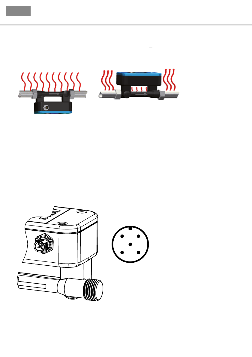
Anwendung mit heißen Flüssigkeiten
Bei Anwendungen in denen der FFU höheren Erwärmungen (t > 60 °C) ausgesetzt ist, wird empfohlen, das Messgerät mit dem Elektronikgehäuse nach unten zu montieren. Somit kann die Wärme
nach oben abstrahlen und die Belastung der Geräteelektronik wird reduziert.
Richtig Falsch
4.3 Elektrischer Anschluss
Der FFU wird über eine fertig konfektionierte Leitungsdose mit M12x1-Steckverbinder, 5-polig oder
8-polig angeschlossen. Leitungsdose spannungsfrei auf den Sensor aufstecken und festschrauben.
Leitung gemäß ihrer Funktion anschließen. Nach Anlegen der Versorgungsspannung führt der Sensor
einen Selbsttest durch – im eingebauten Zustand ist nach abgeschlossenem Selbsttest (ca. 4 s) der
Sensor betriebsbereit – das Display zeigt den aktuell gemessenen Messwert an.
4 Inbetriebnahme
4.3.1 Anschlussbild 5-pol. Variante
6 8013863/10L9 /2018-08-01 © SICK AG • Fluidsensorik • Deutschland • Alle Rechte vorbehalten
Page 7
D
FFU Betriebsanleitung
Pin Aderfarbe Funktion Beschreibung
1 Braun L+ Versorgungsspannung 18 V DC … 30 V DC
2 Weiß Digitaler Ausgang Q1
Funktionen:
1. Impuls
2. Leerrohrmeldung
3. Dosierausgang
4. Grenzwertüberwachung
5. Negativ Fluss
3 Blau GND Versorgungsmasse: 0 V
4 Schwarz Kommunikation Kommunikationsschnittstelle
5 Grau Analogausgang QA
Funktionen:
1. Fluss
2. Temperatur
4 Inbetriebnahme
Digitaler Ausgang Q1
Frei einstellbar im Bereich von 0,1 bis 3000 ml/
Impuls in Schritten von 0,1 ml/Impuls, NPN- oder
PNP-Transistor,
max. Last 18 … 30 V / 100 mA.
Programmierbare Ausgabe von 0 V oder 24 V
bei leerem Messrohr.
Programmierbare Ausgabe von 0V oder 24V
bei erreichen der Dosiermenge.
Programmierbare Ausgabe von 0 V oder 24 V bei
Über-/Unterschreitung einer einstellbaren Grenze.
Programmierbare Ausgabe von 0 V oder 24 V
bei negativem Durchuss.
4 ... 20 mA; 0 ... 20 mA
Zum Beispiel: 0 l/min => 4 mA
36 l/min => 20 mA
Alarm => 3,5 mA
(Abhängig vom eingestellten Messbereich)
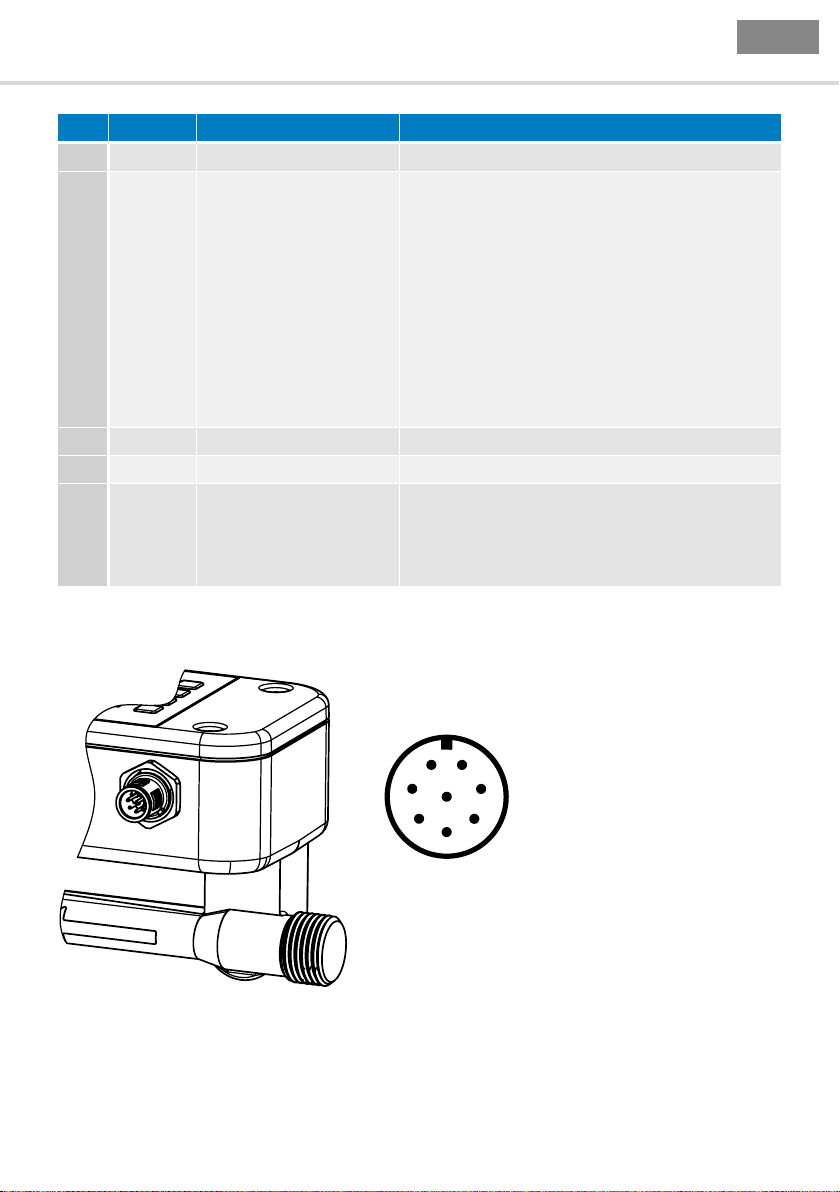
4.3.2 Anschlussbild 8-pol. Variante
8013863/10L9 /2018-08-01 © SICK AG • Fluidsensorik • Deutschland • Alle Rechte vorbehalten
7
Page 8

D
Betriebsanleitung FFU
Pin Funktion Beschreibung
1 L+ Versorgungsspannung 18 V DC … 30 V DC
2 Digitaler Ausgang Q1
Funktionen:
1. Impuls
2. Leerrohrmeldung
3. Dosierausgang
4.Grenzwertüberwachung
5.Negativ Fluss
3 GND Versorgungsmasse: 0 V
4 Digitaler Ausgang Q2
Funktionen:
1. Leerrohrmeldung
2. Impuls
3. Dosierausgang
4.Grenzwertüberwachung
5.Negativ Fluss
5 Analogausgang QA
Funktionen:
1. Fluss
2. Temperatur
6 Kommunikation Kommunikationsschnittstelle
7 Digitaler Eingang IN1
1. Dosiereingang
2. Offsettabgleich
3. Mengenreset
4. Schleichmenge
8 Keine Funktion
4 Inbetriebnahme
Digitaler Ausgang Q1
Frei einstellbar im Bereich von 0,1 bis 3000 ml/Impuls in
Schritten von 0,1 ml/Impuls, NPN- oder PNP-Transistor,
max. Last 18 ... 30 V / 100mA.
Programmierbare Ausgabe von 0 V oder 24 V
bei leerem Messrohr.
Programmierbare Ausgabe von 0V oder 24V
bei erreichen der Dosiermenge.
Programmierbare Ausgabe von 0 V oder 24 V bei Über-/
Unterschreitung einer einstellbaren Grenze.
Programmierbare Ausgabe von 0 V oder 24 V
bei negativem Durchuss.
Digitaler Ausgang Q2
Frei einstellbar im Bereich von 0,1 bis 3000 ml/Impuls in
Schritten von 0,1 ml/Impuls, NPN- oder PNP-Transistor,
max. Last 18 ... 30 V / 100 mA.
Programmierbare Ausgabe von 0 V oder 24 V
bei leerem Messrohr.
Programmierbare Ausgabe von 0V oder 24V
bei erreichen der Dosiermenge.
Programmierbare Ausgabe von 0 V oder 24 V bei Über-/
Unterschreitung einer einstellbaren Grenze.
Programmierbare Ausgabe von 0 V oder 24 V
bei negativem Durchuss.
4 ... 20 mA; 0 ... 20 mA
Zum Beispiel: 0 l/min => 4 mA
36 l/min => 20 mA
Alarm => 3,5 mA
(Abhängig vom eingestellten Messbereich)
Digitaler Eingang IN1
Startet den Dosiervorgang bei 24 V Flanke.
Startet Offsetabgleich bei 24 V Flanke.
Reset des Mengenzählers bei 24 V Flanke
Deaktiviert die Schleichmengenunterdrückung wenn 24
V anliegen.
Die Adernfarben bei 8-poligen Kabeln sich nicht einheitlich. Bitte beachten Sie immer die Anschlussbelegung des Sensors.
8 8013863/10L9 /2018-08-01 © SICK AG • Fluidsensorik • Deutschland • Alle Rechte vorbehalten
Page 9

D
FFU Betriebsanleitung
5 Bedienung
ACHTUNG: Sollte der Durchusssensor FFU für ein anderes Medium als Wasser eingesetzt werden,
ist im Zuge der Inbetriebnahme unbedingt bei gefülltem Gerät die Funktion „Grundabgleich“ über
das Gerätedisplay durchzuführen. Während des Abgleichs darf das Medium nicht ießen, da dies die
Funktion beeinusst.
5.1 Inbetriebnahmeprozedur
Wird der FFU als Durchussmessgerät für Wasser oder wasserähnliche Flüssigkeiten eingesetzt,
benötigt dieser vor Ort i.d.R. keine Bedienung, da die nachfolgend genannten Parameter eine
Werkseinstellung erhalten haben, die eine optimale Funktion gewährleistet.
Die folgenden Parameter können zur Einstellung auf individuelle Verhältnisse verändert werden:
Für 5-pol. Variante
■
Digitaler Ausgang 1 (Q1), Funktion und Verhalten
■
Analoger Ausgang (QA)
■
Flussbereich, Stromausgang
■
Impulswertigkeit
■
Schleichmengenunterdrückung
Die folgenden Parameter können zur Einstellung auf individuelle Verhältnisse verändert werden:
Für 8-pol. Variante
■
Digitaler Ausgang 1 (Q1), Funktion und Verhalten
■
Digitaler Ausgang 2 (Q2) , Funktion und Verhalten
■
Analoger Ausgang (QA)
■
Flussbereich, Stromausgang
■
Impulswertigkeit
■
Schleichmengenunterdrückung
■
Digitaler Eingang (IN1).
5 Bedienung
5.2 Display und Menü
FFU ist erhältlich mit einem Display zur Anzeige von aktuellen Messwerten, sowie zur Einstellung von
applikationsspezischen Parametern. Über die vier Tasten der Folientastatur kann man durch das
Menü navigieren und Einstellungen vornehmen. Durch drücken der Taste „Set“, gelangt man in das
Hauptmenü. Von hier aus lassen sich verschiedene Untermenüs auswählen. Die Menünavigation
erfolgt über die beiden Pfeiltasten. Um einen Menüpunkt zu bestätigen, ist erneut die Taste „Set“ zu
drücken. Für die Eingabe von Grenzwerten wie z.B. unter „Analogausgang – Bereich max“ erfolgt die
Einstellung der gewünschten Zahlen über die Pfeiltasten. Der eingegebene Wert, wird übernommen,
sobald die Taste „Set“ gedrückt wird. Um in den Menüebenen zurückzuschalten, drückt man die
Taste „Esc“. Sobald ein Parameter über das Displaymenü geändert werden soll, muss ein Passwort
eingegeben werden. Dadurch wird sichergestellt, das nur befugte Mitarbeiter Änderungen an den
Geräteparametern vornehmen können. Das Menüpasswort im Auslieferzustand lautet 00338
(FFU auf der Handytastatur: F=3/F=3/U=8).
Der Benutzer bleibt nach dem letzten Tastendruck für einen Zeitraum von 300 Sekunden eingeloggt. 200
Sekunden nach dem letzten Tastendruck springt das Gerät aus dem Menü zurück in den Anzeigemodus.
8013863/10L9 /2018-08-01 © SICK AG • Fluidsensorik • Deutschland • Alle Rechte vorbehalten
9
Page 10
D
Betriebsanleitung FFU
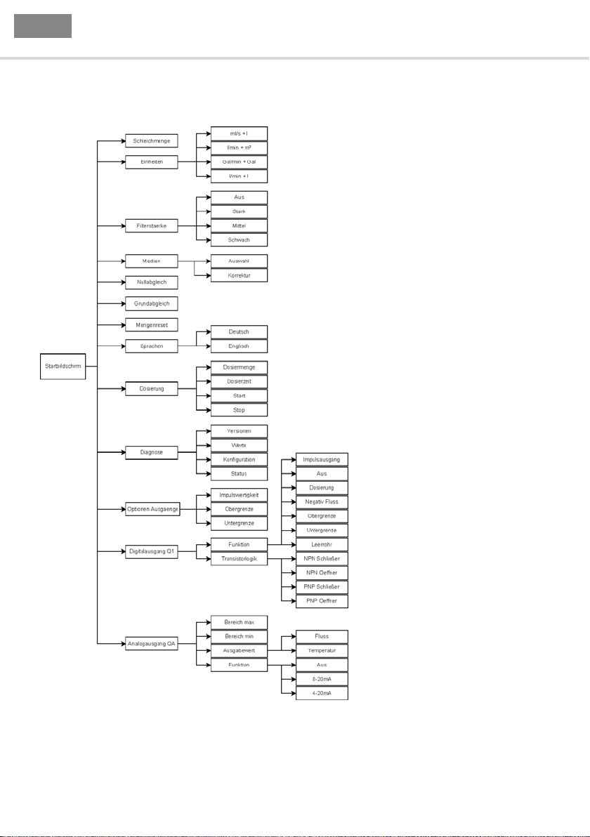
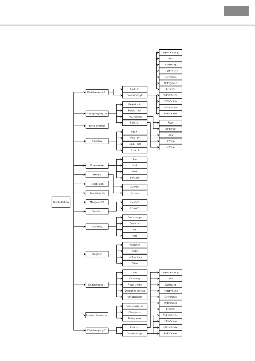
5.3 Menü-Übersicht
5 Bedienung
Menüstruktur 5-pol. Variante
10 8013863/10L9 /2018-08-01 © SICK AG • Fluidsensorik • Deutschland • Alle Rechte vorbehalten
Page 11
D
FFU Betriebsanleitung
5 Bedienung
Menüstruktur 8-Pol. Variante
8013863/10L9 /2018-08-01 © SICK AG • Fluidsensorik • Deutschland • Alle Rechte vorbehalten
11
Page 12

D
Betriebsanleitung FFU
Nullabgleich
Über den Menüpunkt „Nullabgleich“ kann man einen Nullussabgleich durchführen. Damit der
Abgleich korrekt durchgeführt werden kann, muss das Gerät, mit Flüssigkeit gefüllt sein und es darf
kein Durchuss vorhanden sein.
Geringe Nullpunktänderungen z.B. durch Temperaturschwankungen, werden durch den Sensor
automatisch nachgeführt. Es ist ebenfalls möglich, den Nullabgleich über den programmierbaren
Digitaleingang durchzuführen.
Sprachen
Die Sprache für die Anzeige und Menütexte kann geändert werden. Unter dem zugehörigen Untermenü „Sprachen“ kann standardmäßig zwischen Deutsch und Englisch ausgewählt werden.
Filterstärke
Die Funktion „Filterstärke“ bestimmt die Mittelwertbildung der Displayanzeige und des Analogausganges. Einstellungsmöglichkeiten: Schwach, Mittel, Stark, Aus
Bei schwacher Mittelwertbildung, reagiert das ausgegebene Analogsignal schneller. Bei starker
Mittelwertbildung ist die Reaktion des Analogwertes träge.
Einheiten
FFU kann aktuelle Messwerte und gezählte Volumina in verschiedenen Einheiten anzeigen. Im Untermenü lassen sich folgende Einheiten auswählen: ml/s + l, Gal/min +Gal , l/min + l , l/min + m³.
Beispiel: ml/s + l
Hier wird der Durchuss in der Einheit „ml/s“ und die Tagesmenge in „l“ (Liter) angezeigt.
Mengenreset
Über diese Funktion kann die gezählte Tagesmenge des FFU zurückgesetzt werden. Achtung, versehentlich gelöschte Zählerstände können nicht wiederhergestellt werden. Nach dem Reset beginnt die
Zählung wieder beim Wert „0“.
5 Bedienung
Grundabgleich
Die Funktion „Grundabgleich“ ermöglicht eine optimale Anpassung auf die mediumsspezischen
Eigenschaften. Durch Ausführen dieser Funktion durchläuft der FFU eine interne Parametrierung und
passt alle relevanten Parameter selbstständig an. Dieser Vorgang kann bis ca. 1 Minute dauern.
Damit der Abgleich korrekt durchgeführt werden kann, muss das Gerät mit Flüssigkeit gefüllt sein
und es darf kein Durchuss vorhanden sein.
Wenn ein Fehler während des Abgleichs festgestellt wird, z.B. weil das Gerät nicht gefüllt ist,
erscheint „Fehler“ auf dem Display. Wenn der Abgleich erfolgreich durchlaufen wurde, wird die
Meldung „Durchgeführt“ angezeigt.
12 8013863/10L9 /2018-08-01 © SICK AG • Fluidsensorik • Deutschland • Alle Rechte vorbehalten
Page 13
D
FFU Betriebsanleitung
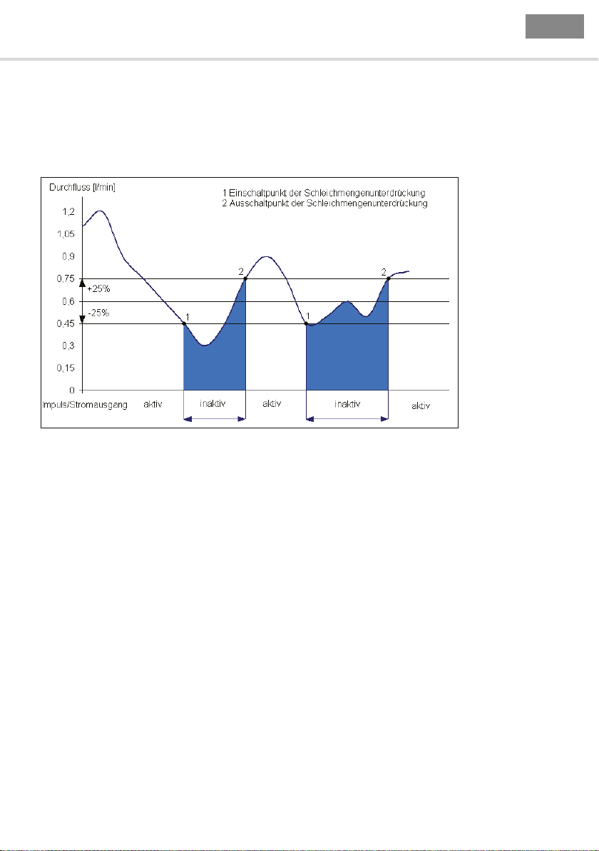
Schleichmenge
Die Schleichmengenunterdrückung dient dazu Durchüsse, die sich in einem kleinen Rahmen um
Null bewegen, von der Messung auszuschließen. Die Schleichmengenunterdrückung wird werkseitig
auf einen in Relation zum Querschnitt des Messgerätes stehenden, sinnvollen Standardwert eingestellt. Unterhalb der Werkseinstellung gibt es größere Toleranzen. Die Schleichmengenunterdrückung
arbeitet mit einer Hysterese von ±25 %.
5 Bedienung
Funktion der Schleichmengenunterdrückung am Beispiel 0,6 l/min
Beispiel: Schleichmengenunterdrückung = 0,6 l/min
Unterschreitet der Durchuss einen Wert von 0,45 l/min, so wird der Impulsausgang/Analogausgang
inaktiv. Bei Überschreiten von 0,75 l/min wird die Durchussmenge wieder als Impuls ausgegeben
und auf den Tagesmengenzähler addiert. Ebenso wird wieder ein Wert auf den Analogausgang ausgegeben.
Einstellbereich: 0,0 ... 20,0 l/min, in Schritten von 0,006 l/min
Werkseinstellung: 0,3 l/min bei DN10
0,9 l/min bei DN15
3,5 l/min bei DN20
5,0 l/min bei DN25
Diagnose
Unter dem Menüpunkt „Diagnose“ können aktuelle Geräteparameter wie z.B. Softwareversionen etc.
eingesehen werden. Diese Informationen werden im Servicefall benötigt.
8013863/10L9 /2018-08-01 © SICK AG • Fluidsensorik • Deutschland • Alle Rechte vorbehalten
13
Page 14

D
Betriebsanleitung FFU
Analogausgang QA
Der Analogausgang steht als Stromausgang 0 ... 20 mA oder 4 ... 20 mA zur Verfügung. Standardmäßig ist der Stromausgang im 4 ... 20mA Modus aktiviert. Er kann über das Displaymenü ausgeschal-
tet oder umkonguriert werden. Der Stromausgang gibt Ströme zwischen 0 und 22 mA als Maß für
den aktuellen Fluss bzw. den Zustand des Messrohrs aus.
Dabei bedeuten am Beispiel 4 ... 20 mA:
■
20 mA signalisiert, die Obergrenze des zu betrachtenden Messbereichs
■
4 mA signalisiert, die Untergrenze des zu betrachtenden Messbereichs
■
3,8 mA signalisiert, Unterschreitung der Untergrenze
■
22 mA signalisiert, Überschreitung der Obergrenze
■
3,5 mA signalisiert, leeres Messrohr
Ober- und Untergrenze können innerhalb des typenspezischen Messbereichs des Gerätes frei
parametriert werden. Standardmäßig ist der Nulluss auf 0 bzw. 4 mA und der jeweilige Endwert des
Messbereiches auf 20 mA gesetzt.
Einstellbereich: 0 ... 20 mA, 4 ... 20 mA, aus
Ausgabewerte: Fluss, Temperatur
Wenn der Stromausgang verwendet wird, sollte der maximale Widerstand nicht über 500 Ohm ansteigen, da sonst nicht sichergestellt ist, dass das Messgerät den Maximalwert von 22 mA liefern kann.
Dosierung
Über das Dosiermenü kann eine manuelle Dosierung konguriert werden. Hierzu ist es möglich die
gewünschte „Dosiermenge“ und eine „Dosierzeit“ einzugeben. Die Dosierzeit ist als Sicherheit gegen
eine ungewollte Überfüllung gedacht, kann aber auch bei Eingabe des Wertes „Null“ deaktiviert
werden. „Start“ und „Stop“ einer Dosierung kann ebenfalls über das Menü ausgeführt werden.
Einstellbereich „Dosiermenge“: 0 – 3500 Liter
Einstellbereich „Dosierzeit“: 0 –30000 Sekunden
Werksteinstellung „Dosiermenge“: 0 Liter
Werkseinstellung „Dosierzeit“: 3 Sekunden
5 Bedienung
Impulswertigkeit
Hier wird vorgegeben, für welche Durchussmenge ein Ausgangsimpuls ausgegeben wird. Die Einstellung ist so zu wählen, dass sowohl die max. Ausgangsfrequenz des FFU (10 kHz) als auch die max.
Eingangsfrequenz der Steuerung nicht überschritten werden.
Beispiel: 2,0 ml/Impuls
Bedeutet: alle 2,0 ml wird ein Impuls ausgegeben.
Einstellbereich: 0,1...3000,0 ml/Impuls in Schritten von 0,1 ml/Impuls
Werkseinstellung: 1,0 ml/Impuls
Digitalausgang Q1
Der digitale Ausgang Q1 kann als Impulsausgang, zur Signalisierung der Leerrohrmeldung, zur Grenzwertüberwachung oder zur Überwachung der Flussrichtung benutzt werden. Über das Gerätedisplay
kann je nach Anwendung die NPN- oder PNP-Logik ausgewählt werden.
Einstellungen: Aus, Impulsausgang, Leerrohr, Untergrenze, Obergrenze, Negativ Fluss
Digitalausgang Q2
Der digitale Ausgang Q2 kann zur Signalisierung der Leerrohrmeldung, Grenzwertüberwachung oder
zur Flussrichtungsüberwachung benutzt werden. Über das Gerätedisplay kann je nach Anwendung
die NPN- oder PNP-Logik ausgewählt werden.
14 8013863/10L9 /2018-08-01 © SICK AG • Fluidsensorik • Deutschland • Alle Rechte vorbehalten
Page 15
D
FFU Betriebsanleitung
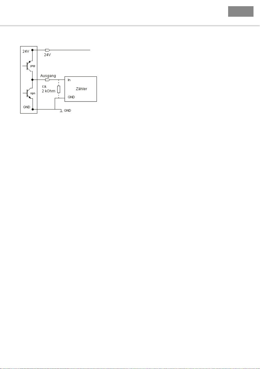
Beispiel 2: FFU über PNP, externer Zähler z.B. SPS
Anschluss von Ausgang 2 an einem Zähler
Einstellungen: Aus, Impulsausgang, Leerrohr, Untergrenze, Obergrenze, Negativ Fluss
Medium
FFU besitzt eine Mediummatrix mit 8 Stützpunkten. Über den Menüpunkt „Medium“ ist es möglich,
Datensätze einzelner Medien zu verwalten. Dadurch können ermittelte Matrixwerte im Gerät gespeichert und für den Einsatz verschiedenster Medien bei Bedarf geladen werden.
Digitaleingang IN1
FFU besitzt einen digitalen Eingang, welchem die Funktionen: Dosierstart, Offsetabgleich, Reset
Menge oder deaktivieren der Schleichmenge zugeordnet werden können. Beispielsweise, ist zum
Starten eines Dosiervorgangs die Leitung gegen 24V zu legen. Die Dosierparameter werden über
das Displaymenü eingestellt. Der Digitaleingang ist entprellt, so dass ein Neustart während eines
laufenden Dosiervorgangs nicht möglich ist. Wenn Funktionen über Display geändert werden, ist ein
Neustart des Gerätes nötig um die Funktion zu aktivieren.
5 Bedienung
Beispiel Dosierung
Grundsätzlich kann die Dosierung auf zwei Arten realisiert werden:
1) FFU als Dosiergerät (Dosiersteuerung über FFU)
FFU übernimmt die komplette Dosiersteuerung. Hierzu wird über das Gerätedisplay die Dosiermenge (z.B. 400 ml) fest eingestellt. Der Dosierstart erfolgt, sobald die Leitung Dosierstart (8-poliger
Stecker, Digitaleingang I1, Anschlusspin 7), z.B. über einen Taster, auf 24V gelegt wird. FFU öffnet
daraufhin über den hierfür kongurierten Ausgang (z.B. Digitalausgang Q1) das Dosierventil. Bei
Erreichen der zuvor eingestellten Dosiermenge wird das Dosierventil über den o.g. Ausgang Q1
geschlossen. Ein Dosiervorgang kann auch über das Gerätedisplay gestartet bzw. gestoppt werden.
Folgende Einstellung sind dazu notwendig:
Einstellung der Dosiermenge im Menü
Dosierung → Dosiermenge → 400 ml
Einstellung der max. Dosierzeit die aus sicherheitsgründen zugelassen werden soll.
Digitaleingang I1 auf Dosierung einstellen
Schaltausgang Q1 auf Dosierung einstellen
8013863/10L9 /2018-08-01 © SICK AG • Fluidsensorik • Deutschland • Alle Rechte vorbehalten
15
Page 16

D
Betriebsanleitung FFU
2) FFU als Durchussmessgerät (Dosiersteuerung über externe Dosieranlage)
Die Dosieranlage übernimmt die komplette Dosiersteuerung. Hierzu wird die Dosiermenge über eine
Vorwahl von Zählimpulsen in der Dosieranlagensteuerung fest eingestellt. Der Dosierstart erfolgt,
sobald der entsprechende Taster an der Dosieranlage betätigt wird. Die Steuerung öffnet daraufhin
das Dosierventil. FFU gibt ab diesem Zeitpunkt für jede durchgeossene Volumeneinheit (z.B. pro
1ml) einen Spannungsimpuls an die Steuerung. Bei Erreichen der Impulsvorwahlmenge wird das
Dosierventil über die Steuerung geschlossen. Ausgang Q1 wird in diesem Fall für die Ausgabe der
Impulse genutzt, der Ausgang 2 kann unabhängig davon wahlweise zur Leerrohrerkennung, Flussrichtungskontrolle oder Grenzwertüberwachung oder Fehlerausgang genutzt werden.
Folgende Einstellung sind dazu notwendig:
Einstellung der Impulsfunktion
Digitalausgang Q1/Q2 im Menü auf Funktionen auf Impulsausgang setzen
Im Menü Optionen Ausgänge unter Impulswertigkeit die Impulswertigkeit z.B. 1ml pro Impuls einstellen.
6 Werkseinstellung
Funktion Werkseinstellung
Digitaler Ausgang 1 (Q1) Impulsausgang
Digitaler Ausgang 2 (Q2) Leerrohrerkennung
Digitaler Eingang 1 (IN1) Ohne Funktion
Stromausgang (QA) 4 mA … 20 mA
Impulswertigkeit 1 ml/Impuls
Schleichmenge 0,3 l/min bei DN10
6 Werkseinstellung
0,9 l/min bei DN15
3,5 l/min bei DN20
5,0 l/min bei DN25
6.1 Allgemeine Hinweise
Vor dem ersten Einschalten des Messgerätes sollten Sie nochmals folgende Kontrollen durchführen:
■
Überprüfen der elektrischen Anschlüsse und Kabelbelegungen
■
Überprüfen der Einbaulage des Messgerätes. Stimmt die Pfeilrichtung auf dem Gehäuse/Typen-
schild mit der tatsächlichen Durchussrichtung in der Rohrleitung überein?
■
Ist die Messleitung vollständig mit Flüssigkeit gefüllt?
■
Ist der entsprechende Gegendruck vorhanden
Der FFU ist betriebsbereit.
16 8013863/10L9 /2018-08-01 © SICK AG • Fluidsensorik • Deutschland • Alle Rechte vorbehalten
Page 17
D
G 1/2
M12x1
5
Alle Maße in mm
M12x1
5
Alle Maße in mm
G 1
M12x1
5
Alle Maße in mm
M12x1
5
Alle Maße in mm
FFU Betriebsanleitung
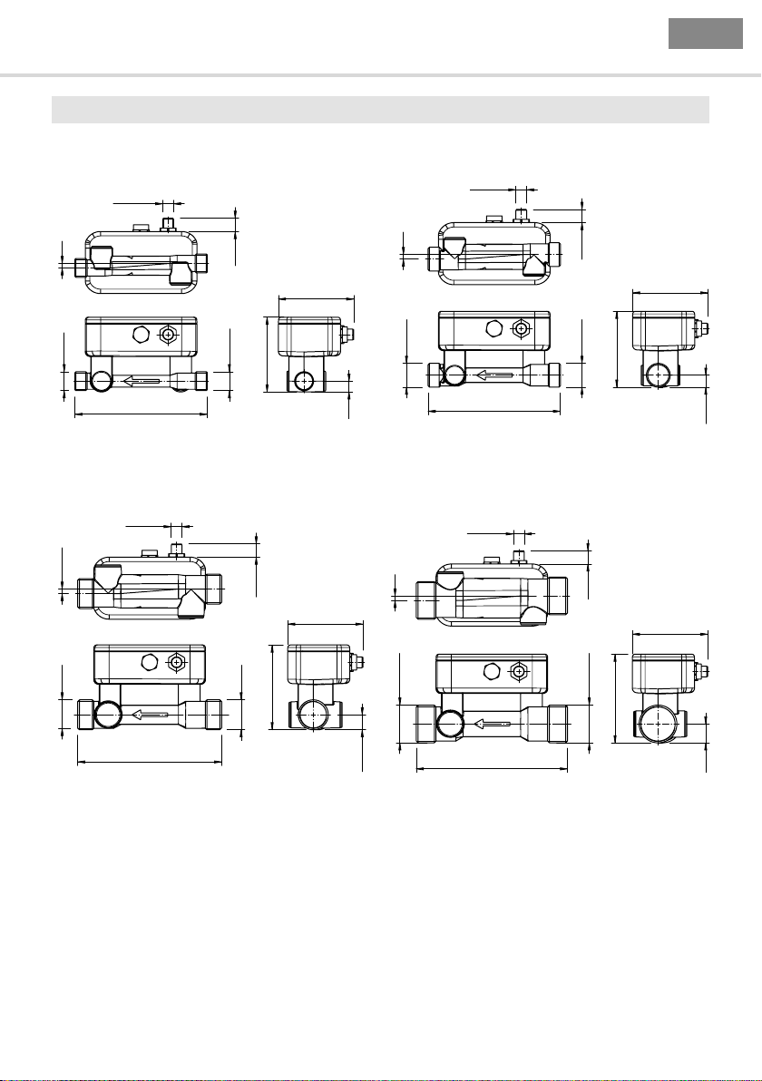
7 Maßzeichnung
DN10, Prozessanschluss G 1/2 DN15, Prozessanschluss G 3/4
7 Maßzeichnung
14,7
84
G 3/4
147
147
G 1/2
83,1
12
DN20, Prozessanschluss G 1 DN25, Prozessanschluss G 1 1/4
14.7
84
G 1
94.2
160
G 1 1/4
16.6
168
14,7
84
G 3/4
84,3
13,2
14,7
84
G 1 1/4
98,6
21
8013863/10L9 /2018-08-01 © SICK AG • Fluidsensorik • Deutschland • Alle Rechte vorbehalten
17
Page 18

D
34
M12x1
5
Alle Maße in mm
M12x1
5
Alle Maße in mm
M12x1
5
Alle Maße in mm
M12x1
5
Alle Maße in mm
Betriebsanleitung FFU
DN10, Clamp (DIN 11864-3) DN15, Clamp (DIN 11864-3)
7 Maßzeichnung
14,7
Clamp (DIN 11864-3 ) DN 10
34
149
84
88,1
17
Clamp (DIN 11864-3 ) DN 15
34
149
DN20, Clamp (DIN 11864-3) DN25, Clamp (DIN 11864-3)
14,7
102,8
84
25,2
Clamp (DIN 11864-3 ) DN 25
50,5
170
Clamp (DIN 11864-3 ) DN 20
50,5
50,5
162
14,7
84
34
88,1
17
14,7
84
50,5
102,8
25,2
18 8013863/10L9 /2018-08-01 © SICK AG • Fluidsensorik • Deutschland • Alle Rechte vorbehalten
Page 19

D
1/2" NPT
M12x1
5
Alle Maße in mm
3/4" NPT
M12x1
5
Alle Maße in mm
M12x1
5
Alle Maße in mm
1 1/4" NPT
M12x1
5
Alle Maße in mm
FFU Betriebsanleitung
DN10, 1/2“ NPT DN15, 3/4“ NPT
7 Maßzeichnung
14,7
84
1/2" NPT
83,1
147
12
147
DN20, 1“ NPT DN25, 1 1/4“ NPT
14,7
84
1" NPT
160
1" NPT
94,4
168
16,8
14,7
84
3/4" NPT
84,4
13,3
14,7
84
1 1/4" NPT
98,9
21,3
8013863/10L9 /2018-08-01 © SICK AG • Fluidsensorik • Deutschland • Alle Rechte vorbehalten
19
Page 20

D
Betriebsanleitung FFU
8 Technische Daten
Merkmale
Messprinzip Ultraschallsensor
Medium Flüssigkeiten
Messrohrnennweite DN10 DN15 DN20 DN25
Prozesstemperatur 0°C ... +80°C
Prozessdruck Max. 16 bar Max. 10 bar
EHEDG-Zertikat
Performance
Minimaler Durchuss
Maximaler Durchuss 21 l/min 36 l/min 60 l/min 240 l/min
Einlaufstrecke 10 cm 30 cm 40 cm 40 cm
Auslaufstrecke 0 cm 5 cm 10 cm 20 cm
Leitfähigkeit Keine Einschränkung
Genauigkeit
2)
Reproduzierbarkeit 0,5 %
Auösung 0,003 l/min 0,006 l/min 0,012 l/min 0,03 l/min
1)
Bei konstantem Durchuss
2)
Referenzbedingung: Medium: Wasser, gasfrei, vollständig gefülltes Messrohr, keine Kavitation, Mediumstemperatur
20°C, Umgebungstemperatur 20°C ... 25°C, Einhaltung der Ein- und Auslaufstrecken, Warmlaufzeit Elektronik: 30 min
1)
8 Technische Daten
DN10 DN15 DN20 DN25
l
DN10 DN15 DN20 DN25
0,3 l/min 0,9 l/min 3,5 l/min 5 l/min
2% (vom Endwert)
Optional 1% vom Messwert +/- 3 mm/s
Mechanik
DN10 DN15 DN20 DN25
Prozessanschluss G 1/2
1/2“ NPT
Clamp 11864
G 3/4
3/4“ NPT
Clamp 11864
G 1
1“ NPT
Clamp 11864
G 1 1/4
1 1/4“ NPT
Clamp 11864
Medienberührende Werkstoffe PSU
Gehäusematerial PSU
Schutzart IP 67
Gewicht 340 g 350 g 420 g 460 g
20 8013863/10L9 /2018-08-01 © SICK AG • Fluidsensorik • Deutschland • Alle Rechte vorbehalten
Page 21

D
FFU Betriebsanleitung
Elektrik
Versorgungsspannung
Restwelligkeit
Stromaufnahme
1)
2)
3)
Initialisierungszeit
Ansprechzeit
4)
Schutzklasse III
Anschlussart M12x1, 5-pol
Elektronik
1)
Ausgangslast < 500 Ohm
Unterer Signalpegel 3,8 mA ... 4 mA
Oberer Signalpegel 20 mA ... 20,5 mA
Impuls/Frequenzausgang 0 kHz ... 10 kHz
Pulsbreite
Signalspannung HIGH U
Signalspannung LOW
Ausgangsstrom
5)
Induktive Last 1 H
Kapazitive Last 100 nF
1)
Alle Anschlüsse sind verpolsicher. Alle Ausgänge sind überlast- und kurzschlussgeschützt.
2)
Darf Uv-Toleranz nicht über- oder unterschreiten.
3)
Ohne Last.
4)
Analogausgang und Anzeige.
5)
Je Ausgangsstufe stehen 100 mA bei PNP und NPN zur Verfügung.
8 Technische Daten
18 V DC ... 30 V DC
< 5 V
ss
< 180 mA
< 5 s
Filter aus 100 ms, Filter schwach 300 ms, Filter mittel 1 s,
Filter stark 4,2 s
M12x1, 8-pol
(typabhängig)
1 Analogausgang: 4 mA ... 20 mA, 0 mA ... 20 mA für aktuellen Durch-
uss und Temperatur, 1 Impuls/Statusausgang: PNP-Transistorausgang für Mengenzählung, Leerrohrüberwachung, Durchussgrenzwert,
Dosierausgang, Durchußrichtung /
1 Analogausgang: 4 mA ... 20 mA, 0 mA ... 20 mA für aktuellen Durch-
uss und Temperatur, 2 Impuls/Statusausgänge: PNP-Transistorausgang für Mengenzählung, Leerrohrüberwachung, Durchussgrenzwert,
Dosierausgang, Durchußrichtung , 1 Digitaleingang für Dosierung,
Mengenreset (typabhängig)
< 1 s
- 2 V
V
< 2 V
< 100 mA
Umgebungsdaten
Umgebungstemperatur
0 °C ... +60 °C
Betrieb
Umgebungstemperatur
-20 °C ... +70 °C
Lager
8013863/10L9 /2018-08-01 © SICK AG • Fluidsensorik • Deutschland • Alle Rechte vorbehalten
21
Page 22

D
Betriebsanleitung FFU
Digitale Ausgänge
Allgemein
Alle Ausgänge werden bei Unterschreitung von 18 V hochohmig. Die digitalen Ausgänge werden bei
Kurzschluss oder Überlastungsfall nach ca. 100 µs für 2 s hochohmig gestellt. Danach wird erneut
versucht den Ausgang zu betätigen.
Leerrohr Ausgang
NPN Öffner Hochohmig 0 V
NPN Schließer 0 V Hochohmig
PNP Öffner Hochohmig 24 V
PNP Schließer 24 V Hochohmig
Impulsausgang
NPN Öffner 0 V 0 V 0 V Impulse
NPN Schließer 0 V 0 V 0 V Impulse
PNP Öffner Hochohmig Hochohmig 24 V Impulse
PNP Schließer Hochohmig Hochohmig 24 V Impulse
8 Technische Daten
Leeres Messrohr Befülltes Messrohr
Leeres Messrohr Stehendes Medium Fließendes Medium
Ausgang als Obergrenze
Unterhalb Unter-
grenze
NPN Öffner Hochohmig Hochohmig 0 V
NPN Schließer 0 V 0 V Hochohmig
PNP Öffner Hochohmig Hochohmig 24 V Impulse
PNP Schließer 24 V 24 V Hochohmig
Zwischen Unter/
Obergrenze
Über Obergrenze
Ausgang als Untergrenze
Unterhalb Unter-
grenze
NPN Öffner 0 V Hochohmig Hochohmig
NPN Schließer Hochohmig 0 V 0 V
PNP Öffner 24 V Hochohmig Hochohmig
PNP Schließer Hochohmig 24 V 24 V
22 8013863/10L9 /2018-08-01 © SICK AG • Fluidsensorik • Deutschland • Alle Rechte vorbehalten
Zwischen Unter/
Obergrenze
Über Obergrenze
Page 23

D
Strom Ausgang 0...20mA
0
2
4
6
8
10
12
14
16
18
20
22
24
-20-10 0102030405060708090100 110120
Wert [%]
Strom [mA]
FFU Betriebsanleitung
Bei Dosierungen sollte der Ausgang nicht als Öffner konguriert werden!
Nach einen Neustart und bis zum Ende einer Dosierung würde das Ventil dauerhaft offen bleiben.
Bei Kongurationsänderung des Einganges ist ein Neustart des Gerätes erforderlich.
8 Technische Daten
Ausstarten des
Gerätes
Bei Dosieren Vor/nach
der Dosierung
NPN Öffner Hochohmig Hochohmig 0 V
NPN Schließer Hochohmig 0 V Hochohmig
PNP Öffner Hochohmig Hochohmig 24 V
PNP Schließer Hochohmig 24 V Hochohmig
Kennlinien Analogausgang
0 bis 20 mA
Für die Darstellung wurde „Bereich min“ als 0 % und „Bereich max“ als 100 % verwendet.
Wert Strom
kleiner 0 % 0 mA
0 % (Bereich min) 0 mA
zwischen 0 % und 100 % Linearinterpolation von 0 mA bis 20 mA
100 % (Bereich max) 20 mA
größer 100 % 20 mA
8013863/10L9 /2018-08-01 © SICK AG • Fluidsensorik • Deutschland • Alle Rechte vorbehalten
23
Page 24

D
Wert [%]
Strom [mA]
Temperatur (%)
Betriebsanleitung FFU
4 bis 20 mA
Für die Darstellung wurde „Bereich min“ als 0 % und „Bereich max“ als 100 % verwendet.
8 Technische Daten
24
22
20
18
16
14
12
10
8
6
4
2
0
-20-10 0102030405060708090 100 110 120
Strom Ausgang 4...20mA
Wert Strom
Leeres Messrohr 3,5 mA
kleiner -1,2 % 3,8 mA
zwischen -1,2 % und 0 % Linearinterpolation von 3,8 mA bis 4 mA
0 % (Bereich min) 4 mA
zwischen 0 % und 100 % Linearinterpolation von 4 mA bis 20 mA
100 % (Bereich max) 20 mA
zwischen 100 % und 102,5 % Linearinterpolation von 20 mA bis 20,4 mA
größer 102,5 % 22 mA
Verhalten des Temperaturfühlers
Der Temperaturfühler ist nicht Mediumberührt, er dient dazu die Ausdehnung des Messkanals zu
berechnen. Der Fühler wird von die Umgebungstemperatur beeinusst. Der Temperaturwert reagiert
träge, da er die Kunststoff -Temperatur innerhalb der Sensortasche misst.
Sprungantwortzeit
Antwort des Temperaturfühlers nach einem Temperatursprung. (Filter auf „Aus“)
100
Sprungantwortzeit
80
60
40
20
0
0510 15 20 25 30 35 40 45
Zeit (min)
24 8013863/10L9 /2018-08-01 © SICK AG • Fluidsensorik • Deutschland • Alle Rechte vorbehalten
Page 25

D
Wert (%)
FFU Betriebsanleitung
Filtereinstellungen
8 Technische Daten
100
80
60
40
20
0
0123 4
Sprung Antwort Temperatur filter
aus
schwach
mittel
stark
Zeit (min)
Filter 100%
aus 1 s
schwach 16 s
mittel 1 min
stark 4 min
Umgebungstemperatureinuss
Beispiel von Einüssen der Raumtemperatur auf den gemessenen Wert.
Medium Temperatur x 0,7 + Umgebungstemperatur x 0,3 = Gemessene Temperatur
40°C x 0,7 + 20°C x 0,3 = 34°C
40°C x 0,7 + 30°C x 0,3 = 37°C
40°C x 0,7 + 40°C x 0,3 = 40°C
60°C x 0,7 + 20°C x 0,3 = 48°C
Verhalten bei Fehler
Bei Kurzschluss des Temperaturfühlers werden –50°C angezeigt.
Bei Kabelbruch zwischen Sensor und Platine werden –30°C angezeigt.
8013863/10L9 /2018-08-01 © SICK AG • Fluidsensorik • Deutschland • Alle Rechte vorbehalten
25
Page 26

D
Sprung An twort Analog Au sgang
01234
Wert [%]
Betriebsanleitung FFU
Filtereinstellungen Analogausgang
100
80
8 Technische Daten
60
40
20
0
aus
schwar
mittel
stark
Zeit [s]
Filter Reaktionszeit
aus 0,1 s
schwach 0,3 s
mittel 1 s
stark 4,2 s
Digital Eingang
Allgemein
Bei Kongurationsänderung des Einganges, ist ein Neustart des Gerätes
erforderlich damit die Einstellung aktiv ist.
Unterschiedliche Kongurationen des Einganges
Nullabgleich Schleichmenge aus Dosierung Reset Zähler aus
0 V – – – – –
24 VPositive Flanke:
0–> 24 V
Abbleich
Nur bei stehendem Medium ausführen
Zustand:
Deaktivierung der
Schleichmenge
Positive Flanke:
0–> 24 V
Dosierungsart
Positive Flanke:
0–> 24 V
Zählerstand wird
zurückgesetzt
Die Eingangs-Funktionen „Nullabgleich“ darf nur bei stehendem Medium durchgeführt werden.
Wird ein Nullabgleich bei aktivem Fluss durchgeführt, kann es zu Fehlmessungen kommen, bis der
Abgleich korrekt durchgeführt wurde.
–
26 8013863/10L9 /2018-08-01 © SICK AG • Fluidsensorik • Deutschland • Alle Rechte vorbehalten
Page 27

D
FFU Betriebsanleitung
9 Zubehör
9.1 Leitungen
Kurzbeschreibung Typ Artikelnr.
Stromversorgungsleitung, M12, 5-pol., Stecker gerade/offenes Ende,
2 m, PVC
Stromversorgungsleitung, M12, 5-pol., Stecker gerade/offenes Ende,
2 m, PUR halogenfrei
Stromversorgungsleitung, M12, 5-pol., Stecker gerade/offenes Ende,
5 m, PVC
Stromversorgungsleitung, M12, 5-pol., Stecker gerade/offenes Ende,
5 m, PUR halogenfrei
Stromversorgungsleitung, M12, 5-pol., Stecker gerade/offenes Ende,
10 m, PVC
Stromversorgungsleitung, M12, 5-pol., Stecker gerade/offenes Ende,
10 m, PUR halogenfrei
Stromversorgungsleitung, M12, 5-pol., Stecker abgewinkelt/offenes
Ende, 2 m, PVC
Stromversorgungsleitung, M12, 5-pol., Stecker abgewinkelt/offenes
Ende, 2 m, PUR halogenfrei
Stromversorgungsleitung, M12, 5-pol., Stecker abgewinkelt/offenes
Ende, 5 m, PVC
Stromversorgungsleitung, M12, 5-pol., Stecker abgewinkelt/offenes
Ende, 5 m, PUR halogenfrei
Stromversorgungsleitung, M12, 5-pol., Stecker abgewinkelt/offenes
Ende, 10 m, PUR halogenfrei
Stromversorgungsleitung, M12, 8-pol., Stecker gerade/offenes Ende,
2 m, PVC
Stromversorgungsleitung, M12, 8-pol., Stecker gerade/offenes Ende,
2 m, PUR halogenfrei
Stromversorgungsleitung, M12, 8-pol., Stecker gerade/offenes Ende,
5 m, PVC
Stromversorgungsleitung, M12, 8-pol., Stecker gerade/offenes Ende,
5 m, PUR halogenfrei
Stromversorgungsleitung, M12, 8-pol., Stecker gerade/offenes Ende,
10 m, PVC
Stromversorgungsleitung, M12, 8-pol., Stecker gerade/offenes Ende,
10 m, PUR halogenfrei
Stromversorgungsleitung, M12, 8-pol., Stecker abgewinkelt/offenes
Ende, 2 m, PVC
Stromversorgungsleitung, M12, 8-pol., Stecker abgewinkelt/offenes
Ende, 2 m, PUR halogenfrei
Stromversorgungsleitung, M12, 8-pol., Stecker abgewinkelt/offenes
Ende, 5 m, PVC
8013863/10L9 /2018-08-01 © SICK AG • Fluidsensorik • Deutschland • Alle Rechte vorbehalten
9 Zubehör
DOL-1205-G02M 6008899
DOL-1205-G02MC 6025906
DOL-1205-G05M 6009868
DOL-1205-G05MC 6025907
DOL-1205-G10M 6010544
DOL-1205-G10MC 6025908
DOL-1205-W02M 6008900
DOL-1205-W02MC 6025909
DOL-1205-W05M 6009869
DOL-1205-W05MC 6025910
DOL-1205-W10MC 6025911
DOL-1208-G02MA 6020633
DOL-1208-G02MC 6035620
DOL-1208-G05MA 6020993
DOL-1208-G05MC 6035621
DOL-1208-G10MA 6022152
DOL-1208-G10MC 6035622
DOL-1208-W02MA 6020992
DOL-1208-W02MC 6035623
DOL-1208-W05MA 6021033
27
Page 28

D
Betriebsanleitung FFU
Kurzbeschreibung Typ Artikelnr.
Stromversorgungsleitung, M12, 8-pol., Stecker abgewinkelt/offenes
Ende, 5 m, PUR halogenfrei
Stromversorgungsleitung, M12, 8-pol., Stecker abgewinkelt/offenes
Ende, 10 m, PUR halogenfrei
10 Rücksendung
Unbedenklichkeitserklärung (Kontaminationserklärung im Servicefall)
Spülen bzw. säubern Sie ausgebaute Geräte vor der Rücksendung, um unsere Mitarbeiter und die
Umwelt vor Gefährdung durch anhaftende Messstoffreste zu schützen.
Eine Überprüfung ausgefallener Geräte kann nur erfolgen, wenn das vollständig ausgefüllte Rücksendeformular vorliegt. Eine solche Erklärung beinhaltet alle Materialien, welche mit dem Gerät in Berührung kamen, auch solche, die zu Testzwecken, zum Betrieb oder zur Reinigung eingesetzt wurden.
Das Rücksendeformular ist über unsere Internet-Adresse (www.sick.com) verfügbar.
11 Entsorgung
Entsorgen Sie Gerätekomponenten und Verpackungsmaterialien entsprechend den einschlägigen
landesspezischen Abfallbehandlungs- und Entsorgungsvorschriften des Anliefergebietes.
10 Rücksendung
DOL-1208-W05MC 6035624
DOL-1208-W10MC 6035625
28 8013863/10L9 /2018-08-01 © SICK AG • Fluidsensorik • Deutschland • Alle Rechte vorbehalten
Page 29

EN
FFU Operating instructions
1 Principle of operation
Swimming against the stream requires greater physical strength than swimming with the stream. This
is the simple fact on which ultrasonic ow measurement according to the phase difference process is
based. Two sensors positioned opposite one another send and receive ultrasonic signals in alternation. When static media are used, both sensors receive the sent ultrasonic signal in phase, meaning
without phase difference. If owing media are used, there is a phase shift. The phase shift is different
when measured in the direction of current than when measured against the direction of current. The
phase difference is directly proportional to the speed of the ow. The ow volume is determined from
the speed of the ow and the known diameter of the pipeline.
2 Safety notes
■
Read the instruction manual before commissioning.
■
Connection, mounting, and setting only to be done by trained specialists.
■
The FFU is not a safety module according to the EU Machinery Directive.
■
Observe the national safety and work safety regulations.
■
Repairs may only be carried out by the manufacturer. Changing or altering the device is not permitted.
■
Wiring work and opening and closing of electrical connections are only to be carried out in a
de-energized state.
■
Incorrect handling or improper use can lead to malfunctions in your application.
■
FFU can be used by the Pressure Equipment Directive (PED) of group 2 only for „non-hazardous
liquids.“
1 Principle of operation
3 Applications
The FFU ow meter is particularly suited for measuring highly dynamic processes in pipelines. The
device measures liquids. It can be used in the following applications, to name but a few:
■
Chemical supply for controlling, logistics and monitoring
■
Filling processes in the food industry
■
Production machines for controlling and monitoring formulae
■
Valve control for dosing liquid volumes
■
DI water supply
■
Dynamic processes
The following featured comprise its performance characteristics:
■
no moving parts, and thus no wear
■
high reproducibility
■
ease of cleaning
■
tamper-proof
■
compact design
■
integrated empty pipe detection
■
chemical resistance
■
integrated display with membrane keyboard
8013863/10L9 /2018-08-01 © SICK AG • Fluid sensors • Germany • Subject to change without notice
29
Page 30

EN
Operating instructions FFU
4 Commissioning
4.1 Installation notes
An arrow on the measuring channel of the FFU indicates the ow measurement direction. The measuring device must be installed such that the ow passes through the measuring tube in the direction of
the arrow.
TOP -> Outlet
BOTTOM -> Inlet
Optimal FFU mounting orientation
To detect gases as quickly as possible, the pipeline between the storage container and the FFU
should be as short as possible. An error-free measurement can only be ensured when the pipeline
is completely full and when no liquid is being released as gas. In the case of dosing applications, it
may be useful to position the FFU as close to the dosing valve as possible, because tubing tends to
expand in diameter depending on system pressure. This can lead to deviations.
4 Commissioning
To avoid cavitations, depending on the measured liquid it can be helpful to have sufcient back-
pressure on the outlet of FFU.
If any solid particles are present, this can lead to measurement errors.
When pumps are used, the ow sensor must be mounted in the ow direction behind the pump (on
the delivery side) in order to ensure that adequate pressure will be available. The maximum pressure
rating of the FFU must be observed. In order to ensure correct volume ow measurement using the
FFU, in inlet and output paths should be straight and free of obstacles. The minimum inlet and output
paths are dependant on the nominal size:
DN10 DN15 DN20 DN25
Inlet zone 10 cm 30 cm 40 cm 40 cm
Outlet zone 0 cm 5 cm 10 cm 20 cm
Always make sure that the maximum torque of the nuts for the hydraulic connections is not overstep.
Please use the supplied seals. If you seal with teon tape that can result in to excessive tightening
torques. We commend a maximum torque depending on the diameter of:
DN10 DN15 DN20 DN25
Torque G 2 Nm 3 Nm 4 Nm 6 Nm
30 8013863/10L9 /2018-08-01 © SICK AG • Fluid sensors • Germany • Subject to change without notice
Page 31

EN
FFU Operating instructions
Caused by the material characteristics of PSU FFU has a limited resistance against UV rays. Remind
this when mounting Flowmax outdoor.
4.2 Mounting
The measuring device is mounted in the pipeline using a process connection. In order to ensure optimal gas
venting, we recommend mounting the FFU vertically in the pipe. The device should not be mounted behind
an output valve, or it might run idle. To prevent outgassing and bubble formation in the media during the
ow measurement, the FFU should always be mounted on the pressure side of the system pump.
4 Commissioning
If the device cannot be mounted vertically, the pipe in which the measuring device is located should
always be full. Preventing the formation of gas bubbles in the FFU measuring channel will aid optimal
measurements.
For applications with a „Clean Design“ when complete drain of the measuring tube is needed, we
recommend to mount the ow meter in vertical position. When ow meter is mounted horizontal
caused by the internal geometry of the device there might be a rest of liquid inside.
Attention: The process connections from the FFU are offset by 5 mm (see dimensional drawing on
page 43-45)
Mounted FFU must alway be mechanically stress free. Strong tension in the pipe system can lead to
damage to the devise. Shocks or mechanical loads can affect the measurement accuracy of the measuring device. If the FFU must be additionally secured due to the presence of vibrations or mechanical
motion, two mounting clamps can be mounted to the inlet and outlet of the measuring device.
FFU with mounting clamps
8013863/10L9 /2018-08-01 © SICK AG • Fluid sensors • Germany • Subject to change without notice
31
Page 32

EN
Operating instructions FFU
Application with hot uids
In applications where the FFU is subject to high heat (t < 60 °C), we recommend mounting the
measuring device and electronic housing beneath the measurement area. This allows the heat to
radiate upwards and reduces its effects on the device electronics.
Correct positioning False positioning
4.3 Electrical connection
The FFU is connected via a ready-made cable socket with M12x1 plug, with 5 pins or 8 pins. Plug in
the cable socket without power onto the sensor and screw it tight. Connect the cable in accordance
with its function. After application of the supply voltage, the sensor carries out a self-test – in an
installed state, the sensor is ready for operation after the self-test has been concluded (ca. 4 s) – the
display shows the current measured value.
4 Commissioning
4.3.1 Connection diagram 5-pin variant
32 8013863/10L9 /2018-08-01 © SICK AG • Fluid sensors • Germany • Subject to change without notice
Page 33

EN
FFU Operating instructions
Pin Wire colour Function Description
1 brown L+ Supply voltage 18 V DC … 30 V DC
2 white Digital output Q1
Functions:
1. Pulse
2. Empty pipe detection
3. Dosing output
4. Threshold monitoring
5. Negative ow
3 blue GND Supply ground: 0 V
4 black Communication Communication interface
5 grey Analog output QA
Functions:
1. Flow
2. Temperature
4 Commissioning
Digital output Q1
Can be freely set in the range of 0.1 to 3000 ml/pulse
in stages of 0.1 ml/pulse, npn or pnp transistor,
max. load 18 ... 30 V / 100mA.
Programmable output of 0 V or 24 V when measuring
tube is empty.
Programmable output of 0 V or 24 V when dosing
volume is reached.
Programmable output of 0 V or 24 V when a preset
threshold is exceeded or not reached.
Programmable output of 0 V or 24 V during negative
ow.
4 ... 20 mA; 0 ... 20 mA
For example: 0 l/min => 4 mA
36 l/min => 20 mA
Alarm => 3,5 mA
(dependent on set measuring area)
4.3.2 Connection diagram 8-pin variant
8013863/10L9 /2018-08-01 © SICK AG • Fluid sensors • Germany • Subject to change without notice
33
Page 34

EN
Operating instructions FFU
Pin Function Description
1 L+ Supply voltage 18 V DC … 30 V DC
2 Digital output Q1
Functions:
1. Pulse
2. Empty pipe detection
3. Dosing output
4. Threshold monitoring
5. Negative ow
3 GND Supply ground: 0 V
4 Digital output Q2
Functions:
1. Empty pipe detection
2. Pulse
3. Threshold monitoring
4. Negative ow
5 Analog output QA
Functions:
1. Flow
2. Temperature
6 Communication Communication interface
7 Digital input IN1
1. Dosing input
2. Offsett compensation
3. Reset counter
4. Creeping ow
8 No Function
4 Commissioning
Digital output Q1
Can be freely set in the range of 0.1 to 3000 ml/pulse in
stages of 0.1 ml/pulse, npn or pnp
transistor,
max. load 18 ... 30 V / 100 mA.
Programmable output of 0 V or 24 V when
measuring tube is empty.
Programmable output of 0 V or 24 V when a preset
threshold is exceeded or not reached.
Programmable output of 0 V or 24 V during
negative ow.
Digital output Q2
Can be freely set in the range of 0.1 to 3000 ml/pulse in
stages of 0.1 ml/pulse, npn or pnp transistor,
max. load 18 ... 30 V / 100 mA.
Programmable output of 0 V or 24 V when
measuring tube is empty.
Programmable output of 0 V or 24 V when a preset
threshold is exceeded or not reached.
Programmable output of 0 V or 24 V during
negative ow.
4 ... 20 mA; 0 ... 20 mA
For example: 0 l/min => 4 mA
36 l/min => 20 mA
Alarm => 3,5 mA
(dependent on set measuring area)
Digital input IN1
Starts the dosage by a rising edge of 24V.
The Offset is set by a rising edge of 24V.
Reset of the counter by a rising edge of 24V.
Creeping suppression is deactivated as long as
there are 24V at the input..
The wire colors in 8-pin cables are not standardized. Please always take note of the sensor‘s pin
assignment.
34 8013863/10L9 /2018-08-01 © SICK AG • Fluid sensors • Germany • Subject to change without notice
Page 35

EN
FFU Operating instructions
5 Operation
WARNING: If the FFU ow sensor is being used for a media other than water, the “Basic Trim” function
must be carried out via the device display during commissioning when the device is lled with uid.
The medium should not be owing during the adjustment, since this affects the operation of the
function.
5,1 Commissioning procedure
If the FFU is being used as a ow meter for water or liquids similar to water, it generally does not
require an on-site adjustment because the factory setting parameters listed below ensure optimal
function.
The following parameters can be adjusted and set in accordance with individual circumstances.
For 5-pin variant
■
Digital output 1 (Q1), function and behavior
■
Analog output (QA)
■
Flow range for current output
■
Pulse value
■
Creeping suppression
The following parameters can be adjusted and set in accordance with individual circumstances.
For 8-pin variant
■
Digital output 1 (Q1), function and behavior
■
Digital output 2 (Q2), function and behavior
■
Analog output (QA)
■
Flow range for current output
■
Pulse value
■
Creeping suppression
■
Digital input (IN1)
5 Operation
5.2 Display and menu
FFU is available with a display for displaying current measured values as well as for setting applica-
tion-specic parameters. The four pushbuttons on the membrane keyboard can be used to navigate
through the menu and carry out settings. Pressing the “Set” button will return you to the main menu.
The main menu contains a number of submenus for selection. The arrow buttons are used to naviga-
te through the menu. To select a menu item, press the “Set” button again. To input limit values, such
as the value for “Analog output - Max. range”, you should select the desired settings using the arrow
button. The input value will be saved when the “Set” button is pressed. To return to the menu, press
the “Esc” button. You will need to enter a password to make any changes to the parameters via the
display menu. This ensures that only authorized personnel can make changes to the device parameters. The menu password on delivery is 00338 (FFU on the cell phone keyboard: F=3/F=3/U=8).
The user level is valid for 5 minutes after the last press on any button.
8013863/10L9 /2018-08-01 © SICK AG • Fluid sensors • Germany • Subject to change without notice
35
Page 36

EN
Operating instructions FFU
5.3 Menu
5 Operation
Menu 5-pin variant
36 8013863/10L9 /2018-08-01 © SICK AG • Fluid sensors • Germany • Subject to change without notice
Page 37

EN
FFU Operating instructions
5 Operation
Menu 8-pin variant
8013863/10L9 /2018-08-01 © SICK AG • Fluid sensors • Germany • Subject to change without notice
37
Page 38

EN
Operating instructions FFU
Set Offset
In the sub menu “Offset” it is possible to set the actual offset of the ow meter. This function should
just be used when FFU is completely lled with liquid and there is no ow.
A small offset change e.g. caused by variable temperatures is automatically done by the ow meter. It
is also possible to set the offset via the congurable digital inputs.
Language
The language of the display can be changed. Available languages are English and German.
Filter
The function „Filter“ determines the average determination of the analog output signal. Possible
congurations : Soft, Medium, Strong, Off
The analog output signal reacts faster to signal changes when average determination is soft. Whereas the output signal reacts slower when average determination is strong.
Units
FFU is able to show actual ow or the volume in different unities. Following unities can be selected:
ml/s + l , Gal/min +Gal , l/min + l , l/min + m³.
Example: ml/s + l
The rst letters correspond the unity of the ow value. The letters after the + correspond the unity of
the volume value.
Reset Counter
The volume counter of FFU can be reseted. Note, accidentally erased counter values are permanent
lost. After doing a reset the counting starts again at value „0“.
5 Operation
Basic Trim
This function makes sure that the ow meter is conforming to the media specic characteristics.
Through execute this function FFU runs a self conguration which optimises all important parameters.
This process may last app. 1 minute. To make sure the basic trim is correctly done the ow meter has
to be lled with liquid without a ow. When there is an error detected while doing the basic trim the
display shows “Error”. After successful nishing the function basic trim the display shows “Done”.
38 8013863/10L9 /2018-08-01 © SICK AG • Fluid sensors • Germany • Subject to change without notice
Page 39

EN
FFU Operating instructions
Creeping ow
The creeping suppression serves the purpose of excluding ows from the measurement that can
evolve through convection in a narrow frame around zero, even with a closed valve. At the factory, the
creeping suppression is set at a reasonable standard value in relation to the cross-section of the ow
meter. There are higher tolerances below the standard default settings. The creeping suppression
works with a hysteresis of ±25 %.
Function of the creeping ow illustrated with 0.6 l/min
5 Operation
Example: Creeping ow = 0,6 l/min
If the ow rate is lower than 0.45 l/min the pulse output/analog putput becomes inactive. If the ow
rate exceeds 0.75 l/min a pulse is output again and added to the quantity counter. Similarly, a value
is transmitted to the analog output again.
Setting range: 0,0 ... 20 l/min, in 0,006 l/min steps
Default settings: 0,3 l/min for DN10
0,9 l/min for DN15
3,5 l/min for DN20
5,0 l/min for DN25
Diagnostic
The sub menu „Diagnostic“ shows the actual software/hardware version and many helpful values for
analysis. Knowing about the actual values or the state bits makes it easy to review the measurement
by the manufacturer.
8013863/10L9 /2018-08-01 © SICK AG • Fluid sensors • Germany • Subject to change without notice
39
Page 40

EN
Operating instructions FFU
Analog output QA
The analog output is available as current output 4 ... 20 mA or 0 ... 20 mA. Type depending on
purchase order. As a standard it comes with current output 4 ... 20 mA. It can be switched off with
by using the display menu. The current outputs ows from 0 to 22 mA as measure for the ow or the
state of the measuring pipe.
The values here signify for 4 ... 20mA conguration:
■
20 mA the upper limit of the relevant measuring area
■
4 mA the lower limit of the relevant measuring area
■
3.8 mA undershoot the lower limit
■
22 mA overshoot the upper limit
■
3.5 mA empty pipe
Upper and lower limit parameters can be set freely within the type-specic measuring areas of the
device. By default zero ow is set at 4 mA and the respective maximum ow is set at 20 mA.
Setting range: 0 ... 20 mA, 4 ... 20 mA, off
Output value: Flow, temperature
When current output is used make sure the load is not higher than 500 Ohm. A higher load may
cause the device can not provide the maximum current of 22 mA.
Dosing
By using the dosing function via the user display manually dosing is congurable. The volume
„Dosing Batch“ and the „Dosing Time“ are freely adjustable. When the „Dosing Time“ is set to zero
the timer control is inactive. A dosage can be started and stopped with the menu function keys
„Start“ and „Stop“ or can be started by the digital input.
5 Operation
Setting range “Dosing Batch”: 0 – 3500 Liters
Setting range “Dosing Time” 0 –30000 Seconds
Default setting “Dosing Batch”: 0 Liters
Default setting “Dosing Time”: 3 Seconds
Pulse value
This determines for what ow volumes an output pulse will be emitted.
Choose conguration such as to neither exceed the maximum ouptput frequency of the FFU (10 kHz)
nor the maximum input frequency of the control.
Example: 2.0 ml/pulse
This means: a pulse is emitted every 2.0 ml.
Setting range: 0.1 ... 3000.0 ml/pulse, in 0.1 ml/pulse steps
Default setting: 1.0 ml/pulse
Digital output Q1
Digital output Q1 may be used as pulse output, empty pipe detection, limit control or negative ow
(ow direction). By using display it is possible to switch between npn and pnp logic.
Setting area: off, pulse output, empty pipe, lower limit, upper limit, negative ow
Digital output Q2
Digital outputs Q2 may be used as pulse output, empty pipe detection, for switching dosing valve,
limit control or ow direction control. The npn or pnp logic can be chosen.
40 8013863/10L9 /2018-08-01 © SICK AG • Fluid sensors • Germany • Subject to change without notice
Page 41

EN
FFU Operating instructions
Example 2: FFU pnp-out connected to a counter
Connecting output 2 to external counter
Setting area: off, pulse output, empty pipe, lower limit, upper limit, negative ow
Media
FFU dispose of a medium matrix with up to 8 interpolation values. Different medias can be managed
in the sub menu “Media”. Matrix values can be saved and if needed be loaded for different medias.
Digital input IN1
FFÜ has a digital input that is programmable to following functions: dosing input, set offset, creeping
suppression inactive and reset counter. In order to start a dosing process, wiring to 24V DC is requi-
red. The condition is the conguration of the dosing parameters with the user display.
Dosing input is debounced so that re-start is not possible during a running dosing process. After
changing congurations a restart of the device is needed to activate the function.
5 Operation
Dosing can basically be realized in two ways:
1. FFU as dosing device (dosing control FFU)
FFU does the entire dosing control. The dosing quantity (e.g. 400 ml) is pre-set in the FFU using
the user menu of the display. Dosing starts, as soon as line digital input is wired to 24 V, e.g. via a
pushbutton. FFU will now open the dosing valve via the output congured for it. When the pre-set
dosing quantity is reached, the dosing valve is closed via the above output. The dosing procedure can
also be started and stopped by using the dosing user menu. The 2nd output can be used indepen-
dently for signaling of empty pipe detection, limit control or ow direction.
The following settings are necessary:
Adjustment of dosage in the menu
Dosing → Dosing quantity → 400 ml
Setting the max. dosing time that should be allowed for safety reasons.
Digital Input I1 → Dosing
Digital Output Q1/Q2 → Function → Dosing
2. FFU as ow meter (dosing control via dosing equipment)
The dosing equipment is responsible for the entire dosing control. Therefore, the dosing quantity is
xed in the dosing equipment control during commissioning by pre-selecting the meter pulses. Dosing
starts, when the relevant pushbutton of the dosing equipment is pushed. The control will now open
the dosing valve. From now on FFU will send a voltage pulse to the control for each volume unit that
has own through (e.g. per 1ml). When the pre-selected pulse quantity is reached, the control closes
the dosing valve. In this case, output Q1/Q2 is used to send out pulses.
8013863/10L9 /2018-08-01 © SICK AG • Fluid sensors • Germany • Subject to change without notice
41
Page 42

EN
Operating instructions FFU
The following settings are necessary:
Adjustment of puls output in the menu
Digital Output Q1/Q2 ==> Function ==> Pulse Output
Options Output ==> Pulse Value ==> e.g. 1 ml per pulse
6 Overview of default settings
Function Default settings
Digital output 1 (Q1) Pulse output
Digital output 2 (Q2) Empty pipe output
Digital input 1 (IN1) No function assigned
Current output (QA) 4 mA … 20 mA
Pulse value 1 ml/pulse
Creeping suppression 0.3 l/min at NW10
6.1 General instructions
The following checks should be carried out before the measuring device is switched on for the rst
time:
■
Check the electrical connections and the cable conguration
■
Check the measuring device mounting position. Is the direction of the arrow on the housing/type
plate the same as the actual ow direction in the pipeline?
6 Overview of default settings
0.9 l/min at NW15
3.5 l/min at NW20
5.0 l/min at NW25
■
Is the sample line completely lled with liquid?
■
Is there a corresponding counterpressure?
The FFU is ready for operation.
42 8013863/10L9 /2018-08-01 © SICK AG • Fluid sensors • Germany • Subject to change without notice
Page 43

EN
M12x1
5
All dimensions in mm (inch)
M12x1
5
All dimensions in mm (inch)
M12x1
5
All dimensions in mm (inch)
M12x1
5
All dimensions in mm (inch)
FFU Operating instructions
7 Dimensional drawing
NW10, process connection G 1/2 NW15, process connection G 3/4
7 Dimensional drawing
(0.20)
G 3/4
147
(5.79)
(0.20)
G 1/2
147
(5.79)
14.7
(0.58)
84
(3.31)
G 1/2
83.1
(3.27)
12
(0.47)
NW20, process connection G 1 NW25, process connection G 1 1/4
(0.20)
G 1
160
(6.30)
14.7
(0.58)
84
(3.31)
G 1
94.2
(3.70)
(0.20)
G 1 1/4
168
16.6
(0.65)
(6.61)
14.7
(0.58)
G 3/4
84.3
14.7
(0.58)
G 1 1/4
98.6
(3.32)
(3.88)
84
(3.31)
84
(3.31)
13.2
(0.52)
21
(0.83)
8013863/10L9 /2018-08-01 © SICK AG • Fluid sensors • Germany • Subject to change without notice
43
Page 44

EN
34
M12x1
Dimensions in mm (inch)
34
M12x1
5
All dimensions in mm (inch)
50.5
M12x1
5
All dimensions in mm (inch)
M12x1
5
All dimensions in mm (inch)
Operating instructions FFU
NW10, Clamp (DIN 11864-3) NW15, Clamp (DIN 11864-3)
7 Dimensional drawing
5
(0.20)
Clamp (DIN 11864-3 ) DN 10
(1.34)
149
(5.87)
14.7
(0.58)
84
(3.31)
34
(1.34)
88.1
(3.74)
17
(0.67)
(0.20)
Clamp (DIN 11864-3 ) DN 15
1.34)
(
149
(5.87)
NW20, Clamp (DIN 11864-3) NW25, Clamp (DIN 11864-3)
(0.20)
Clamp (DIN 11864-3 ) DN 20
1.99)
(
162
(6.34)
14.7
(0.58)
84
(3.31)
50.5
1.99)
(
102.8
(4.05)
(0.20)
Clamp (DIN 11864-3 ) DN 25
50.5
( 1.99)
170
25.2
(0.99)
(6.69)
34
14.7
50.5
(0.58)
(1.34)
14.7
1.99)
(
88.1
(0.58)
102.8
84
(3.31)
(3.74)
17
(0.67)
84
(3.31)
(4.05)
25.2
(0.99)
44 8013863/10L9 /2018-08-01 © SICK AG • Fluid sensors • Germany • Subject to change without notice
Page 45

EN
M12x1
5
All dimensions in mm (inch)
M12x1
5
All dimensions in mm (inch)
M12x1
5
All dimensions in mm (inch)
M12x1
5
All dimensions in mm(inch)
FFU Operating instructions
NW10, 1/2“ NPT NW15, 3/4“ NPT
7 Dimensional drawing
(0.20)
1/2" NPT
147
(5.79)
14.7
(0.58)
83.1
1/2" NPT
(3.27)
84
(3.31)
12
(0.47)
(0.20)
3/4" NPT
147
(5.79)
NW20, 1“ NPT NW25, 1 1/4“ NPT
16.8
(0.20)
1 1/4" NPT
168
(0.66)
(6.61)
(0.20)
1" NPT
160
(6.30)
14.7
(0.58)
1" NPT
94.4
84
(3.31)
(3.72)
14.7
(0.58)
3/4" NPT
84.4
14.7
(0.58)
1 1/4" NPT
98.9
(3.32)
(3.89)
84
(3.31)
84
(3.31)
13.3
21.3
(0.52)
(0.84)
8013863/10L9 /2018-08-01 © SICK AG • Fluid sensors • Germany • Subject to change without notice
45
Page 46

EN
Operating instructions FFU
8 Technical data
Features
Measuring principle Ultrasonic sensor
Medium Fluids
Nominal width measuring
tube
Process temperature 0 °C ... +80 °C
Process pressure Max. 16 bar Max. 10 bar
EHEDG approval
Performance
Minimum ow
Maximum ow 21 l/min 36 l/min 60 l/min 240 l/min
Inlet zone 10 cm 30 cm 40 cm 40 cm
Outlet zone 0 cm 5 cm 10 cm 20 cm
Conductivity No limitation
Accuracy
Reproducibility 0.5 %
Resolution 0.003 l/min 0.006 l/min 0.012 l/min 0.03 l/min
1)
At constant ow rate.
2)
reference condition:Medium: water, gas-free, fully-lled measuring tube, no cavitation, Medium temperature 20 ° C
Ambient temperature 20 ° C ... 25 ° C, Compliance with the inlet zone and outlet zone, Warm-up time electronic: 30 min
1)
2)
8 Technical data
NW10 NW15 NW20 NW25
NW10 NW15 NW20 NW25
l
NW10 NW15 NW20 NW25
0.3 l/min 0.9 l/min 3.5 l/min 5 l/min
2% (of nal value)
optional 1% of reading +/- 3 mm/s
Mechanics
NW10 NW15 NW20 NW25
Process connection G 1/2
1/2“ NPT
Clamp 11864
G 3/4
3/4“ NPT
Clamp 11864
G 1
1“ NPT
Clamp 11864
G 1 1/4
1 1/4“ NPT
Clamp 11864
Wetted parts PSU
Housing material PSU
Enclosure rating IP 67
Weight 340 g 350 g 420 g 460 g
46 8013863/10L9 /2018-08-01 © SICK AG • Fluid sensors • Germany • Subject to change without notice
Page 47

EN
FFU Operating instructions
Electronics
Supply voltage
Ripple
Power consumption
1)
2)
3)
Initialization time
Response time
4)
Protection class III
Electrical connection M12x1, 5-pin
Electronics
1)
Output load < 500 Ohm
Lower signal level 3.8 mA ... 4 mA
Upper signal level 20 mA ... 20.5 mA
Impuls/frequency output 0 kHz ... 10 kHz
Puls width
Signal voltage HIGH V
Signal voltage LOW
Output current
5)
Inductive load 1 H
Capacitive load 100 nF
1)
All connections are reverse polarity. All outputs are overload and short-circuit protected.
2)
May not exceed or fall short of VS tolerances.
3)
Without load.
4)
Analog output and display.
5)
There are 100 mA for each output pnp and npn available.
8 Technical data
18 V DC ... 30 V DC
< 5 V
PP
< 180 mA
< 5 s
Filter off 100 ms, lter low 300 ms, lter medium 1 s,
lter strong 4.2 s
M12x1, 8-pin
(depending on type)
1 analog output: 4 mA ... 20 mA, 0 mA ... 20 mA current ow and
temperature, 1 pulse/status output: PNP-transistor output for ow
rate meter, empty pipe detection, ow monitoring, dosing output, ow
direction /
1 analog output: 4 mA ... 20 mA, 0 mA ... 20 mA current ow and
temperature, 2 pulse/status output: PNP-transistor output for ow rate
meter, empty pipe detection, ow monitoring, dosing output, ow direc-
tion, 1 digital input for dosing and counter reset (depending on type)
< 1 s
- 2 V
S
< 2 V
< 100 mA
Ambient data
Ambient temperature,
0 °C ... +60 °C
operation
Ambient temperature,
-20 °C ... +70 °C
storage
8013863/10L9 /2018-08-01 © SICK AG • Fluid sensors • Germany • Subject to change without notice
47
Page 48

EN
Operating instructions FFU
Digital output
General
All outputs switch over to high resistance when the supply is smaller than 18 V. When overload or
short circuit is detected the digital outputs were switched off after 100 µs for a period of 2 s. When
time is up the outputs get applied again.
Empty pipe output
NPN normally closed High impedance 0 V
NPN normally open 0 V High impedance
PNP normally closed High impedance 24 V
PNP normally open 24 V High impedance
Pulse output
NPN normally closed 0 V 0 V 0 V pulse
NPN normally open 0 V 0 V 0 V pulse
PNP normally closed High impedance High impedance 24 V pulse
PNP normally open High impedance High impedance 24 V pulse
8 Technical data
Empty pipe Filled pipe
Empty pipe Filled, no ow Filled, ow
Lower limit output
Below lower limit Between the limits Above upper limit
NPN normally closed High impedance High impedance 0 V
NPN normally open 0 V 0 V High impedance
PNP normally closed High impedance High impedance 24 V pulse
PNP normally open 24 V 24 V High impedance
Higher limit output
Below lower limit Between the limits Above upper limit
NPN normally closed 0 V High impedance High impedance
NPN normally open High impedance 0 V 0 V
PNP normally closed 24 V High impedance High impedance
PNP normally open High impedance 24 V 24 V
48 8013863/10L9 /2018-08-01 © SICK AG • Fluid sensors • Germany • Subject to change without notice
Page 49

EN
Current output 0...20mA
0
2
4
6
8
10
12
14
16
18
20
22
24
-20-10 0102030405060708090100 110120
Value [% ]
Current [mA]
FFU Operating instructions
When using the dosing function the output should not be congured as normally closed!
After restart and till the end of a dosing process the valve would be open.
When conguration of the input is changed a device restart is required.Characteristic analog output
NPN normally closed High impedance High impedance 0 V
NPN normally open High impedance 0 V High impedance
PNP normally closed High impedance High impedance 24 V
PNP normally open High impedance 24 V High impedance
Characteristic analog output
0 - 20 mA
For the following graphic “min Range” is used for 0 % and “max Range” is used for 100 %.
8 Technical data
Startup of device While dosing Before/after dosing
Value Current
Smaller 0 % 0 mA
0 % (min range) 0 mA
Between 0 % and 100 % Linear interpolation from 0 mA to 20 mA
100 % (max range) 20 mA
Bigger 100 % 20 mA
8013863/10L9 /2018-08-01 © SICK AG • Fluid sensors • Germany • Subject to change without notice
49
Page 50

EN
Current output 4...20mA
0
2
4
6
8
10
12
14
16
18
20
22
24
-20-10 0102030405060708090100 110120
Value [%]
Current [mA]
Sprungantwortzeit
Temperatur (%)
Zeit (min)
100
80
60
40
20
0
0510 15 20 25 30 35 40 45
Time (min)
Operating instructions FFU
4 - 20 mA
For the following graphic “min Range” is used for 0 % and “max Range” is used for 100 %.
Value Current
Empty pipe 3.5 mA
Smaller -1.2 % 3.8 mA
Between -1.2 % and 0 % Linear interpolation from 3.8 mA to 4 mA
0 % (min range) 4 mA
Between 0 % and 100 % Linear interpolation from 4 mA to 20 mA
100 % (max range) 20 mA
Between 100 % and 102.5 % Linear interpolation from 20 mA to 20.4 mA
Bigger 102.5 % 22 mA
Behavior of the thermocouple
The integrated thermocouple has no direct contact to the liquid and is used to calculate the expansi-
on of the housing. The environment temperature has a big inuence on the measured temperature
of the thermocouple. The response time of temperature changes is very high caused by the mounting
position of the thermocouple inside the housing.
Step-response time
Step-response time after a signicant temperature change. (Filter „Off“)
100
80
60
Temperature (%)
40
20
0
0510 15 20 25 30 35 40 45
50 8013863/10L9 /2018-08-01 © SICK AG • Fluid sensors • Germany • Subject to change without notice
Step-response time
8 Technical data
Page 51

EN
Sprung Antwort Temperatur filter
Zeit (min)
Wert (%)
100
80
60
40
20
0
0123 4
aus
schwach
mittel
stark
FFU Operating instructions
Filter congurations
8 Technical data
100
80
Value (%)
60
40
20
0
0123 4
Step-response with filter
Off
Soft
Medium
Strong
Time (min)
Filter 100%
Off 1 s
Soft 16 s
Medium 1 min
Streng 4 min
Inuence of the environment temperature
In the table below some examples of the temperature inuence are shown.
Liquid temperature x 0,7 + Enviroment temperature x 0,3 = Measured temperature
40°C x 0,7 + 30°C x 0,3 = 37°C
40°C x 0,7 + 40°C x 0,3 = 40°C
60°C x 0,7 + 20°C x 0,3 = 48°C
In case of an error
In case of a short circuit of the thermocouple –50°C are shown.
In case of a cable brake between thermocouple and electronic –30°C are shown.
40°C x 0,7 + 20°C x 0,3 = 34°C
8013863/10L9 /2018-08-01 © SICK AG • Fluid sensors • Germany • Subject to change without notice
51
Page 52

EN
Response time analog output
0
20
40
60
80
100
01234
Time [s]
Value [%]
off
soft
medium
strong
Operating instructions FFU
Filter options for analog output
Filter Response time
off 0.1 s
soft 0.3 s
medium 1 s
strong 4.2 s
8 Technical data
Digital Input
When conguration of the input is changed a device restart is required. After restart the changes
are active.
Available input functions:
Set offset Creeping ow off Dosing Reset counter off
0 V – – – – –
24 VRising edge:
0–> 24 V
Set offset
run only when uid isn‘t owing
The input functions „Set Offset“ shall only be used when there is no ow through the ow meter.
State:
Switch creeping ow
off
Positive edge:
0–> 24 V
Start dosing
State:
0–> 24 V
Counter is reset
When an offset trim is done while liquid ows a measuring deviation is probably until the trim is done
correctly.
52 8013863/10L9 /2018-08-01 © SICK AG • Fluid sensors • Germany • Subject to change without notice
–
Page 53

EN
FFU Operating instructions
9 Accessories
9.1 Cables
Brief description Model name Part no..
Cable, M12, 5-pin, straight connector female with molded cable,
2 m, PVC
Cable, M12, 5-pin, straight connector female with molded cable,
2 m, PUR halogen free
Cable, M12, 5-pin, straight connector female with molded cable,
5 m, PVC
Cable, M12, 5-pin, straight connector female with molded cable,
5 m, PUR halogen free
Cable, M12, 5-pin, straight connector female with molded cable,
10 m, PVC
Cable, M12, 5-pin, straight connector female with molded cable,
10 m, PUR halogen free
Cable, M12, 5-pin, angled connector female with molded cable,
2 m, PVC
Cable, M12, 5-pin, angled connector female with molded cable,
2 m, PUR halogen free
Cable, M12, 5-pin, angled connector female with molded cable,
5 m, PVC
Cable, M12, 5-pin, angled connector female with molded cable,
5 m, PUR halogen free
Cable, M12, 5-pin, angled connector female with molded cable,
10 m, PUR halogen free
Cable, M12, 8-pin, straight connector female with molded cable,
2 m, PVC
Cable, M12, 8-pin, straight connector female with molded cable,
2 m, PUR halogen free
Cable, M12, 8-pin, straight connector female with molded cable,
5 m, PVC
Cable, M12, 8-pin, straight connector female with molded cable,
5 m, PUR halogen free
Cable, M12, 8-pin, straight connector female with molded cable,
10 m, PVC
Cable, M12, 8-pin, straight connector female with molded cable,
10 m, PUR halogen free
9 Accessories
DOL-1205-G02M 6008899
DOL-1205-G02MC 6025906
DOL-1205-G05M 6009868
DOL-1205-G05MC 6025907
DOL-1205-G10M 6010544
DOL-1205-G10MC 6025908
DOL-1205-W02M 6008900
DOL-1205-W02MC 6025909
DOL-1205-W05M 6009869
DOL-1205-W05MC 6025910
DOL-1205-W10MC 6025911
DOL-1208-G02MA 6020633
DOL-1208-G02MC 6035620
DOL-1208-G05MA 6020993
DOL-1208-G05MC 6035621
DOL-1208-G10MA 6022152
DOL-1208-G10MC 6035622
8013863/10L9 /2018-08-01 © SICK AG • Fluid sensors • Germany • Subject to change without notice
53
Page 54

EN
Operating instructions FFU
Brief description Model name Part no..
Cable, M12, 8-pin, angled connector female with molded cable,
2 m, PVC
Cable, M12, 8-pin, angled connector female with molded cable,
2 m, PUR halogen free
Cable, M12, 8-pin, angled connector female with molded cable,
5 m, PVC
Cable, M12, 8-pin, angled connector female with molded cable,
5 m, PUR halogen free
Cable, M12, 8-pin, angled connector female with molded cable,
10 m, PUR halogen free
10 Return
Declaration of no objection (contamination declaration in case of service work)
Rinse off or clean removed devices before returning them in order to protect our employees and the
environment from dangers of residue of measured materials.
Failed devices can only be examined when accompanied by a completely lled-out return form. Such
a declaration includes information about all materials which have come into contact with the device,
including those which were used for testing purposes, operation, or cleaning. The return form is
available at our Internet site (www.sick.com).
10 Return
DOL-1208-W02MA 6020992
DOL-1208-W02MC 6035623
DOL-1208-W05MA 6021033
DOL-1208-W05MC 6035624
DOL-1208-W10MC 6035625
11 Disposal
Dispose of device components and packaging materials in compliance with applicable country-speci-
c waste treatment and disposal regulations of the region of use.
54 8013863/10L9 /2018-08-01 © SICK AG • Fluid sensors • Germany • Subject to change without notice
Page 55

EN
FFU Operating instructions
12 Notes
12 Notes
8013863/10L9 /2018-08-01 © SICK AG • Fluid sensors • Germany • Subject to change without notice
55
Page 56

8013863/10L9 /2018-08-01 ∙ 9PMS (2018-08) ∙ A5 sw int48
Australia
Phone +61 (3) 9457 0600
1800 33 48 02 – tollfree
Austria
Phone +43 (0) 2236 62288-0
Belgium/Luxembourg
Phone +32 (0) 2 466 55 66
Brazil
Phone +55 11 3215-4900
Canada
Phone +1 905.771.1444
Czech Republic
Phone +420 2 57 91 18 50
Chile
Phone +56 (2) 2274 7430
China
Phone +86 20 2882 3600
Denmark
Phone +45 45 82 64 00
Finland
Phone +358-9-25 15 800
France
Phone +33 1 64 62 35 00
Germany
Phone +49 (0) 2 11 53 01
Hong Kong
Phone +852 2153 6300
Hungary
Phone +36 1 371 2680
India
Phone +91-22-6119 8900
Israel
Phone +972-4-6881000
Italy
Phone +39 02 27 43 41
Japan
Phone +81 3 5309 2112
Malaysia
Phone +603-8080 7425
Mexico
Phone +52 (472) 748 9451
Netherlands
Phone +31 (0) 30 229 25 44
New Zealand
Phone +64 9 415 0459
0800 222 278 – tollfree
Norway
Phone +47 67 81 50 00
Poland
Phone +48 22 539 41 00
Romania
Phone +40 356-17 11 20
Russia
Phone +7 495 283 09 90
Singapore
Phone +65 6744 3732
Slovakia
Phone +421 482 901 201
Slovenia
Phone +386 591 78849
South Africa
Phone +27 (0)11 472 3733
South Korea
Phone +82 2 786 6321
Spain
Phone +34 93 480 31 00
Sweden
Phone +46 10 110 10 00
Switzerland
Phone +41 41 619 29 39
Taiwan
Phone +886-2-2375-6288
Thailand
Phone +66 2 645 0009
Tur key
Phone +90 (216) 528 50 00
United Arab Emirates
Phone +971 (0) 4 88 65 878
United Kingdom
Phone +44 (0)17278 31121
USA
Phone +1 800.325.7425
Vietnam
Phone +65 6744 3732
Detailed addresses and further
locations at www.sick.com
SICK AG | Waldkirch | Germany | www.sick.com
 Loading...