

2006/42/EC
NO
SAFETY
8022424.14JQ / 05.06.2019
SICK AG
E
rwin-Sick
-Straße 1
D-79183 Waldkirch
www.sick.com
EventCam
O P E R A T I N G I N S T R U C T I O N S e n
Described product
EventCam
EVC625-CCOXAL5L and EVC625-CCOVAL5L
Legal information
This work is protected by copyright. Any rights derived from the copyright shall be
reserved for SICK AG. Reproduction of this document or parts of this document is
only permissible within the limits of the legal determination of Copyright Law. Any
modification, abridgment or translation of this document is prohibited without the
express written permission of SICK AG.
The trademarks stated in this document are the property of their respective
owner.
© SICK AG. All rights reserved.
Original document
This document is an original document of SICK AG.
Subject to change without notice.
The specified product features and technical data do not represent any guaran‐
tee.
Data integrity:
SICK AG uses standardized data interfaces, such as standard IP technology, in its
products. The emphasis here is on the availability of products and their features.
SICK AG always assumes that the integrity and confidentiality of the data and
rights affected by the use of these products will be ensured by the customer. In all
cases, appropriate security measures, such as network separation, firewalls, virus
protection, and patch management, must be taken by the customer on the basis
of the situation in question.
2.2 Improper use
The EventCam must only be used by appropriately trained specialist personnel
within the limits of the prescribed and specified technical data and operating con‐
ditions at all times.
Any instance of improper use, incorrect modification, or manipulation of the
EventCam shall void any warranty provided SICK AG; furthermore, SICK AG shall
not accept any responsibility or liability for any resulting damage and consequen‐
tial damage.
•
The EventCam is not a safety-related device according to the EU Machinery
Directive.
•
The EventCam must not be used in explosion-hazardous areas.
•
Any use of accessories not specifically approved by SICK AG is at your own
risk.
2.3 Repair
Repair work on the product may only be performed by qualified and authorized
personnel from SICK AG. Interference with or modifications to the product on the
part of the customer will invalidate any warranty claims against SICK AG.
3 Product description
3.1 Structure and function
Structure
1 About this document
1.1 Information on the operating instructions
These operating instructions provide important information on how to use the
camera from SICK AG.
Prerequisites for safe work are:
•
Compliance with all safety notes and handling instructions supplied
•
Compliance with local work safety regulations and general safety regulations
for camera applications
The operating instructions are intended to be used by qualified personnel and
electrical specialists.
NOTE
Read these operating instructions carefully before starting any work on the
sensor, in order to familiarize yourself with the sensor and its functions.
The instructions constitute an integral part of the product and are to be stored in
the immediate vicinity of the camera so they remain accessible to staff at all
times. Should the camera be passed on to a third party, these operating instruc‐
tions should be handed over with it.
These operating instructions do not provide information on operating the machine
in which the camera is integrated. For information about this, refer to the operat‐
ing instructions of the specific machine.
1.2 Scope
These operating instructions serve to incorporate the product into a system.
Instructions are given in stages for all actions required.
These instructions apply to products with the product code EVC625-CCOXAL5L
and EVC625-CCOVAL5L.
Simplified device designation in the document
In the following, the product is referred to as the “EventCam”.
1.3 Customer service
If you require any technical information, our customer service department will be
happy to help.
NOTE
Before calling, make a note of all type label data such as type code, serial
number, etc. to ensure faster processing.
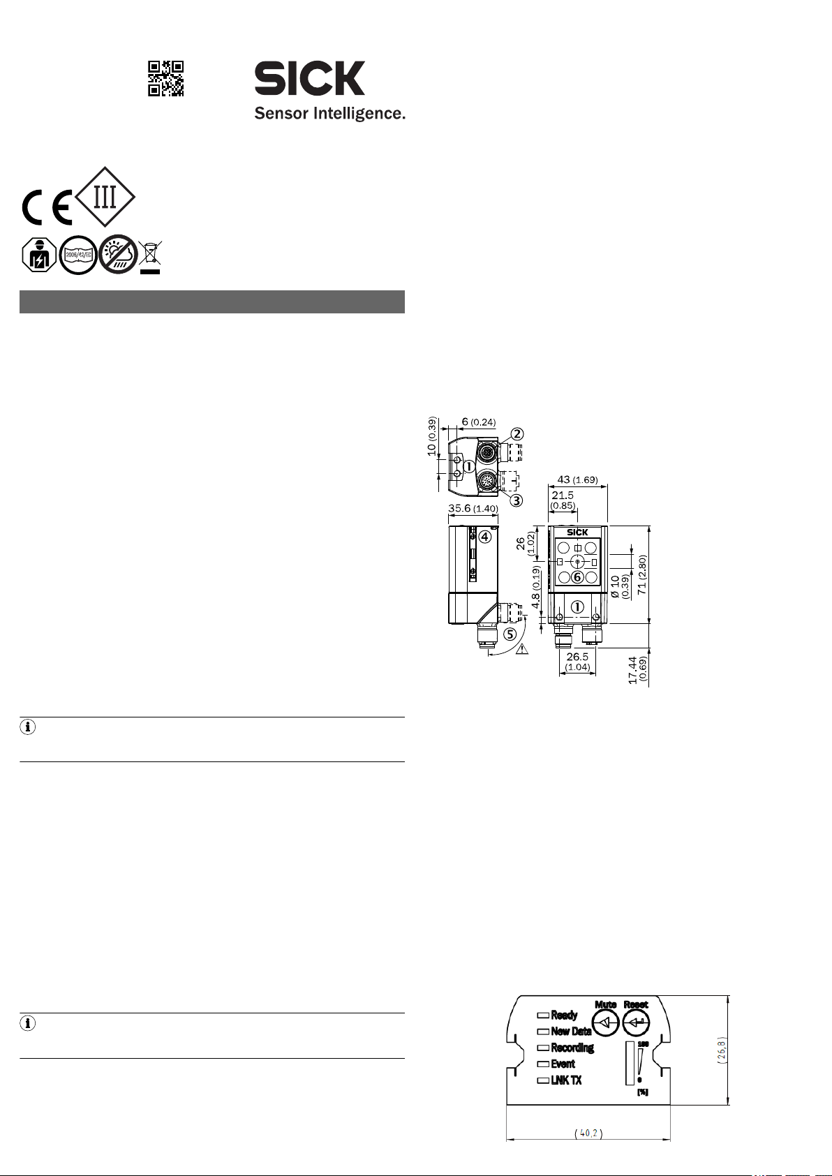
Figure 1: Dimensional drawing
1
2
3
4
5
6
Function
The EventCam records images/video sequences when triggered to do so. The trig‐
ger is an external digital input. The images/video sequences show what happened
immediately before and after the event.
The EventCam has two operating modes:
Operating mode 1: image mode
When a trigger signal is issued, the EventCam records a predefined number of
images before and after the signal.
Operating mode 2: video mode
In video mode, the EventCam records a video sequence with a set time before
and after the trigger signal.
In addition to the two operating modes, a live view is available as a setup aid.
Images can be uploaded directly from the EventCam to an FTP server. Alterna‐
tively, or in addition, data can be stored internally.
3.2 Status indicators
M5 blind-hole thread, 5 mm deep (4x), for mounting
“Ethernet” connection (female connector, M12, 4-pin, D-coded)
“Power/I/O” connection (male connector, M12, 17-pin, A-coded)
M5 sliding nut, 5 mm deep (2x), for mounting (alternative)
Swivel connector
Camera module
2 Safety information
2.1 Intended use
•
For improving process quality by providing additional visual information
•
For performing analyses in conjunction with safety scanners
8022424.14JQ / 05.06.2019/de, en EventCam | SICK 1
Status indicators
3
1
7
2
6
5
4
8
13
14
17
15
9
10
12
16
11
1
43
2
Sens
GND
Trigger
GND
Voltage suply
U
S
PC
Device
muted
Event Cam
Ready New
Data
Storage
Low
Mute
Fuse
max. 2.0 A
Ethernet cable
Male connector
M12, 17 pin,
A-coded
Male connector
M12, 4 pin,
D-coded
Configuration
Data transfer
Data access (SOPAS, Air, FTP)
LED Color Status
Ready
New data
Recording
Event
LNK TX
Ö
Ö
Ö
Ö
Ö
o
Ö
Ö
Ö
o
Ö
Blue Boot process
Blue Device not ready
Green Device ready
Green New event present
Blue Device overheated
No new event
Green Device recording
Blue Device muted
Blue Recording active
Recording not active
Green Data traffic via Ethernet
Mute Switch trigger on/off
Reset Data and settings are deleted if this is
pressed and held for 10 s
Display of the available memory
4 Transport and storage
Transport and store the product in its original packaging, ensuring that the protec‐
tive caps/plugs have been screwed onto the electrical connections. Do not store
outdoors. The product must not be stored in airtight containers, so that any resid‐
ual moisture is able to escape. Do not expose to aggressive media (e.g., solvents
such as acetone). Storage conditions: dry, dust-free, no direct sunlight, storage
temperature –20 °C to 70 °C, as little vibration as possible, relative humidity
max. 90% (non-condensing).
5 Mounting
5.1 Required materials
Direct mounting: 2 or 4 M5 screws for mounting the device on a bracket supplied
by the customer.
Screw lengths are dependent on the mounting base (wall thickness of bracket). If
SICK brackets are being used, the screws for the product are included with deliv‐
ery.
5.2 Mounting requirements
•
The permissible ambient conditions for operating the device must be
observed
•
Stable bracket with sufficient load-bearing capacity and suitable dimensions
for the product
•
Take appropriate measures for vibration damping if vibration and shock
specifications exceed the values and test conditions specified in the data
sheet, see Technical data, page 3
•
To comply with the IP 65 enclosure rating, the following requirements must
be met:
- Do not open the device housing, which is screwed in place
- The cables plugged into the M12 connections are clamped
5.3 Mounting procedure
Perform one of the following steps:
•
Mount the EventCam on a bracket supplied by the customer using M5
screws. To do this, either use the threaded mounting holes in the housing in
pairs at the front or below or use the two M5 sliding nuts in the lateral slots.
Mounting bracket no. 2042902 can be attached at the bottom or on the
sliding nuts. Screw the screws no more than 5 mm into the blind tapped
see figure 1, page 1
holes,
•
Attach the SICK bracket that has been ordered separately (e.g., mounting
bracket no. 2042902) to the EventCam using the two sliding blocks.
•
This sensor is a protection class III device. It must only be used with SELV
(Safety Extra Low Voltage).
•
If the supply voltage for the device is not supplied via the CDB620-001 con‐
nection module, the device must be protected by a separate max. 2.0 A
slow-blow fuse in the supply circuit.
•
Assure professional shielding, especially of data cables. The housing is elec‐
trically connected to the cable shield. Avoid undefined potential equalization
current via housing or shield during installation.
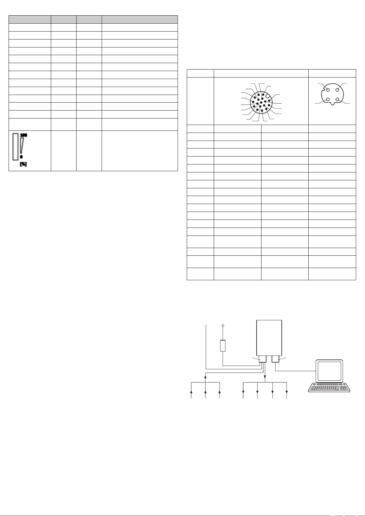
6.2 Pin assignments
Pin assignments
Power/IO Ethernet
Pin Wire color
1)
Signal Signal
1 BU - (M) TX+
2 BN + (L+) RX+
3 GN - TX4 WH - RX5 PK - 6 YE - 7 BK - 8 GY - 9 WH/BK SensGND 10 VT Trigger, switching input 11 GY/PK - 12 RD/BU - 13 WH/GN Ready, switching output 14 BN/GN New Data, switching
output
-
15 WH/YE Mute, switching input 16 YE/BN Device Muted, switching
17 WH/GY Storage low, switching
1)
Wire color valid for SICK-cables with the order numbers 2070425, 2070426, 2070427,
2075220
output
output
-
-
6.3 Connecting the device electrically
1 Connect the communication interface of the device to the PC.
2 Supply power to the device according to the type label.
6 Electrical installation
Figure 2: Connection diagram without connection module
6.1 Safety
6.1.1 Notes on electrical installation
•
•
•
•
•
•
8022424.14JQ / 05.06.2019/de, en EventCam | SICK 2
The electrical installation must only be performed by electrically qualified personnel.
Standard safety requirements must be observed when working on electrical systems.
Only switch on the supply voltage for the device when the connection tasks
have been completed and the wiring has been thoroughly checked.
When using extension cables with open ends, ensure that bare wire ends do
not come into contact with each other (risk of short-circuit when supply volt‐
age is switched on!). Wires must be appropriately insulated from each other.
As an option, the device can be connected via the CDB620-001 connection
module. For more information, see “CDB620-001 connection module operat‐
ing instructions”, 8012119. It is not possible to access the digital outputs
Result 3 and 4 when the connection module is being used.
Wire cross-sections in the supply cable from the user’s power system must
be designed in accordance with the applicable standards.
 Loading...