

Page 1
2006/42/EC
NO
SAFETY
8022424.14JQ / 05.06.2019
SICK AG
E
rwin-Sick
-Straße 1
D-79183 Waldkirch
www.sick.com
EventCam
O P E R A T I N G I N S T R U C T I O N S e n
Described product
EventCam
EVC625-CCOXAL5L and EVC625-CCOVAL5L
Legal information
This work is protected by copyright. Any rights derived from the copyright shall be
reserved for SICK AG. Reproduction of this document or parts of this document is
only permissible within the limits of the legal determination of Copyright Law. Any
modification, abridgment or translation of this document is prohibited without the
express written permission of SICK AG.
The trademarks stated in this document are the property of their respective
owner.
© SICK AG. All rights reserved.
Original document
This document is an original document of SICK AG.
Subject to change without notice.
The specified product features and technical data do not represent any guaran‐
tee.
Data integrity:
SICK AG uses standardized data interfaces, such as standard IP technology, in its
products. The emphasis here is on the availability of products and their features.
SICK AG always assumes that the integrity and confidentiality of the data and
rights affected by the use of these products will be ensured by the customer. In all
cases, appropriate security measures, such as network separation, firewalls, virus
protection, and patch management, must be taken by the customer on the basis
of the situation in question.
2.2 Improper use
The EventCam must only be used by appropriately trained specialist personnel
within the limits of the prescribed and specified technical data and operating con‐
ditions at all times.
Any instance of improper use, incorrect modification, or manipulation of the
EventCam shall void any warranty provided SICK AG; furthermore, SICK AG shall
not accept any responsibility or liability for any resulting damage and consequen‐
tial damage.
•
The EventCam is not a safety-related device according to the EU Machinery
Directive.
•
The EventCam must not be used in explosion-hazardous areas.
•
Any use of accessories not specifically approved by SICK AG is at your own
risk.
2.3 Repair
Repair work on the product may only be performed by qualified and authorized
personnel from SICK AG. Interference with or modifications to the product on the
part of the customer will invalidate any warranty claims against SICK AG.
3 Product description
3.1 Structure and function
Structure
1 About this document
1.1 Information on the operating instructions
These operating instructions provide important information on how to use the
camera from SICK AG.
Prerequisites for safe work are:
•
Compliance with all safety notes and handling instructions supplied
•
Compliance with local work safety regulations and general safety regulations
for camera applications
The operating instructions are intended to be used by qualified personnel and
electrical specialists.
NOTE
Read these operating instructions carefully before starting any work on the
sensor, in order to familiarize yourself with the sensor and its functions.
The instructions constitute an integral part of the product and are to be stored in
the immediate vicinity of the camera so they remain accessible to staff at all
times. Should the camera be passed on to a third party, these operating instruc‐
tions should be handed over with it.
These operating instructions do not provide information on operating the machine
in which the camera is integrated. For information about this, refer to the operat‐
ing instructions of the specific machine.
1.2 Scope
These operating instructions serve to incorporate the product into a system.
Instructions are given in stages for all actions required.
These instructions apply to products with the product code EVC625-CCOXAL5L
and EVC625-CCOVAL5L.
Simplified device designation in the document
In the following, the product is referred to as the “EventCam”.
1.3 Customer service
If you require any technical information, our customer service department will be
happy to help.
NOTE
Before calling, make a note of all type label data such as type code, serial
number, etc. to ensure faster processing.
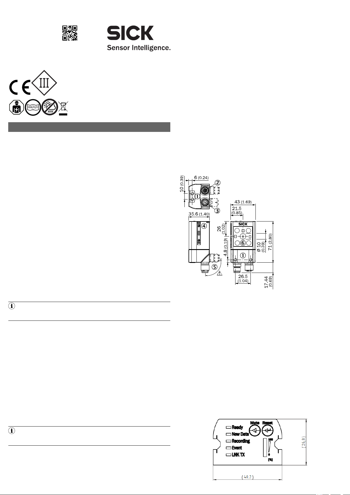
Figure 1: Dimensional drawing
1
2
3
4
5
6
Function
The EventCam records images/video sequences when triggered to do so. The trig‐
ger is an external digital input. The images/video sequences show what happened
immediately before and after the event.
The EventCam has two operating modes:
Operating mode 1: image mode
When a trigger signal is issued, the EventCam records a predefined number of
images before and after the signal.
Operating mode 2: video mode
In video mode, the EventCam records a video sequence with a set time before
and after the trigger signal.
In addition to the two operating modes, a live view is available as a setup aid.
Images can be uploaded directly from the EventCam to an FTP server. Alterna‐
tively, or in addition, data can be stored internally.
3.2 Status indicators
M5 blind-hole thread, 5 mm deep (4x), for mounting
“Ethernet” connection (female connector, M12, 4-pin, D-coded)
“Power/I/O” connection (male connector, M12, 17-pin, A-coded)
M5 sliding nut, 5 mm deep (2x), for mounting (alternative)
Swivel connector
Camera module
2 Safety information
2.1 Intended use
•
For improving process quality by providing additional visual information
•
For performing analyses in conjunction with safety scanners
8022424.14JQ / 05.06.2019/de, en EventCam | SICK 1
Page 2
Status indicators
3
1
7
2
6
5
4
8
13
14
17
15
9
10
12
16
11
1
43
2
Sens
GND
Trigger
GND
Voltage suply
U
S
PC
Device
muted
Event Cam
Ready New
Data
Storage
Low
Mute
Fuse
max. 2.0 A
Ethernet cable
Male connector
M12, 17 pin,
A-coded
Male connector
M12, 4 pin,
D-coded
Configuration
Data transfer
Data access (SOPAS, Air, FTP)
LED Color Status
Ready
New data
Recording
Event
LNK TX
Ö
Ö
Ö
Ö
Ö
o
Ö
Ö
Ö
o
Ö
Blue Boot process
Blue Device not ready
Green Device ready
Green New event present
Blue Device overheated
No new event
Green Device recording
Blue Device muted
Blue Recording active
Recording not active
Green Data traffic via Ethernet
Mute Switch trigger on/off
Reset Data and settings are deleted if this is
pressed and held for 10 s
Display of the available memory
4 Transport and storage
Transport and store the product in its original packaging, ensuring that the protec‐
tive caps/plugs have been screwed onto the electrical connections. Do not store
outdoors. The product must not be stored in airtight containers, so that any resid‐
ual moisture is able to escape. Do not expose to aggressive media (e.g., solvents
such as acetone). Storage conditions: dry, dust-free, no direct sunlight, storage
temperature –20 °C to 70 °C, as little vibration as possible, relative humidity
max. 90% (non-condensing).
5 Mounting
5.1 Required materials
Direct mounting: 2 or 4 M5 screws for mounting the device on a bracket supplied
by the customer.
Screw lengths are dependent on the mounting base (wall thickness of bracket). If
SICK brackets are being used, the screws for the product are included with deliv‐
ery.
5.2 Mounting requirements
•
The permissible ambient conditions for operating the device must be
observed
•
Stable bracket with sufficient load-bearing capacity and suitable dimensions
for the product
•
Take appropriate measures for vibration damping if vibration and shock
specifications exceed the values and test conditions specified in the data
sheet, see Technical data, page 3
•
To comply with the IP 65 enclosure rating, the following requirements must
be met:
- Do not open the device housing, which is screwed in place
- The cables plugged into the M12 connections are clamped
5.3 Mounting procedure
Perform one of the following steps:
•
Mount the EventCam on a bracket supplied by the customer using M5
screws. To do this, either use the threaded mounting holes in the housing in
pairs at the front or below or use the two M5 sliding nuts in the lateral slots.
Mounting bracket no. 2042902 can be attached at the bottom or on the
sliding nuts. Screw the screws no more than 5 mm into the blind tapped
see figure 1, page 1
holes,
•
Attach the SICK bracket that has been ordered separately (e.g., mounting
bracket no. 2042902) to the EventCam using the two sliding blocks.
•
This sensor is a protection class III device. It must only be used with SELV
(Safety Extra Low Voltage).
•
If the supply voltage for the device is not supplied via the CDB620-001 con‐
nection module, the device must be protected by a separate max. 2.0 A
slow-blow fuse in the supply circuit.
•
Assure professional shielding, especially of data cables. The housing is elec‐
trically connected to the cable shield. Avoid undefined potential equalization
current via housing or shield during installation.
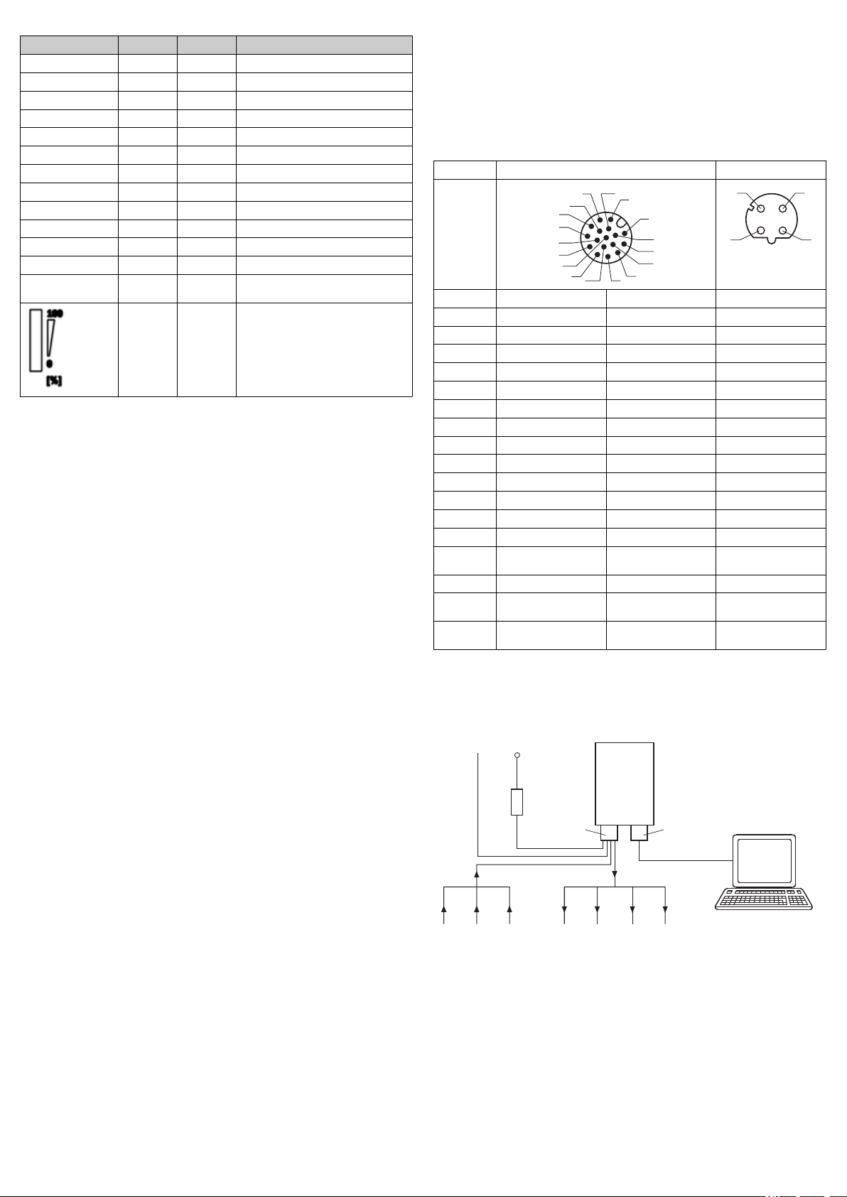
6.2 Pin assignments
Pin assignments
Power/IO Ethernet
Pin Wire color
1)
Signal Signal
1 BU - (M) TX+
2 BN + (L+) RX+
3 GN - TX4 WH - RX5 PK - 6 YE - 7 BK - 8 GY - 9 WH/BK SensGND 10 VT Trigger, switching input 11 GY/PK - 12 RD/BU - 13 WH/GN Ready, switching output 14 BN/GN New Data, switching
output
-
15 WH/YE Mute, switching input 16 YE/BN Device Muted, switching
17 WH/GY Storage low, switching
1)
Wire color valid for SICK-cables with the order numbers 2070425, 2070426, 2070427,
2075220
output
output
-
-
6.3 Connecting the device electrically
1 Connect the communication interface of the device to the PC.
2 Supply power to the device according to the type label.
6 Electrical installation
Figure 2: Connection diagram without connection module
6.1 Safety
6.1.1 Notes on electrical installation
•
•
•
•
•
•
8022424.14JQ / 05.06.2019/de, en EventCam | SICK 2
The electrical installation must only be performed by electrically qualified personnel.
Standard safety requirements must be observed when working on electrical systems.
Only switch on the supply voltage for the device when the connection tasks
have been completed and the wiring has been thoroughly checked.
When using extension cables with open ends, ensure that bare wire ends do
not come into contact with each other (risk of short-circuit when supply volt‐
age is switched on!). Wires must be appropriately insulated from each other.
As an option, the device can be connected via the CDB620-001 connection
module. For more information, see “CDB620-001 connection module operat‐
ing instructions”, 8012119. It is not possible to access the digital outputs
Result 3 and 4 when the connection module is being used.
Wire cross-sections in the supply cable from the user’s power system must
be designed in accordance with the applicable standards.
Page 3

Input 1 (Trigger)
Input 2 (Mute)
Supply voltage
V
S
GNDV
S
PC
Event Cam
CDB620-001
Output 1 (Ready)
Output 2 (New Data)
Ethernet cable
(Male connector M12,
4 pin, D-coded)
Cable
(Male connector,
D-Sub-HD, 15 pin,
Socket M12, 17 pin, A-coded)
Configuration
Data transfer
Data access (SOPAS, Air, FTP)
21
Image mode Video mode
Camera resolution/image rate up to 15 fps (2592x1944,
QSXGA)
15 or 30 fps (1920x1080,
1080p)
15 or 45 fps (1280x720,
720p)
13 or 65 fps (800x600,
SVGA)
Spectral proper ties RGB
Horizontal field of view 44° with QSXGA
Vertical field of view 34° with QSXGA
Figure 3: Connection diagram wit connection module CDB620-001
Diagonal field of view 53° with QSXGA
7 Configuration
7.1 Configuration with PC
The default configuration software SOPAS Air is used to configure the device.
Configure the device before initial commissioning
1 Open browser (Microsoft Edge, Firefox or Chrome) and enter device IP
address (192.168.0.30). If necessary, change PC IP address and subnet
mask.
2 Enter the maintenance level with the password maintenance and set a new
password.
3 Complete the configuration
8 Troubleshooting
Diagnostics/Troubleshooting
Error Cause Measure
Device not ready No voltage supply Check voltage supply
Device not ready - (Ready
LED blue, Recording LED
green)
New Data and Event LEDs are
lighting up blue
Memory full. Ready LED is
lighting up blue
Event not recorded Trigger configuration (low/
FTP data transmission not
working
Device cannot be muted by
pressing button
Image too bright/dark Incorrect exposure setting Switch on Automatic Exposure
Configuration Wizzard not fin‐
ished correctly or missing ini‐
tial configuration
Device is overheating Provide a cooler environment
Internal device memory is full Download data and delete
high) incorrect; trigger dura‐
tion too short; device still
processing previous event;
memory full and/or F TP
transmission error; device
muted
Cause noted in log file Read cause of error in log file;
Mute button deactivated Button can be activated via
Muting via pin is switched on,
which is preventing muting
via button
Open Configuration Wizzard in
the browser and finish it by
pressing the button "Finish"
and/or better heat dissipation
them from device
Change trigger configuration
(min. trigger duration 15 ms);
shorten event duration; ver fiy
if memory is full; unmute
device
log file can be downloaded in
SOPAS Air
SOPAS Air
Deactivate muting via pin in
SOPAS Air
Control if it is switched off or
change manual exposure time
If Automatic Exposure Control
is switched on, increase/
reduce brightness
Image is blurry Object is moving too fast Check exposure settings
Live view and other function‐
alities cannot be displayed in
SOPAS Air
Internet Explorer not sup‐
ported
Use Microsoft Edge 40,
Google Chrome 63 or Firefox
61 browser
9 Maintenance and care
The product is maintenance-free. Check the plastic screen in front of the Event‐
Cam for contamination at regular intervals.
10 Disassembly and disposal
Any device which can no longer be used must be disposed of in an environmen‐
tally friendly manner in accordance with the applicable country-specific waste dis‐
posal regulations. As it is categorized as electronic waste, the device must never
be disposed of with household waste.
11 Technical data
Performance data
Working distance 0.4 m ... 0.6 m (type EVC625-CCOVAL5L)
8022424.14JQ / 05.06.2019/de, en EventCam | SICK 3
Image mode Video mode
0.8 m ... 6.0 m (type EVC625-CCOXAL5L)
Internal memory capacity 35 to 1000 events depending on mode, resolution and
Event duration Max. number of images
Trigger Wired or manual in SOPAS Air
White balance Manual
Internal illumination No
Exposure setting Automatic or manual
Muting Muting using button on device, SOPAS Air configuration
Interfaces
Configuration software SOPAS Air (browser-based)
Data access SOPAS Air (browser-based)
Ethernet connection 100 Mbit/s
Standard network IP 192.168.0.30
Data storage F TP upload and/or internal memory
Image/video format jpg H.264
Mechanics/electronics
Housing material Aluminum die cast
Material reading window Plastic (PMMS) 2 mm thick, scratch
Dimensions 71 mm x 43 mm x 35.6 mm
Weight 170 g
Protection class III
Enclosure rating IP65
Voltage supply 24 V DC ± 20% SELV
Output current per digital output ≤ 50 mA
Power consumption Typ. 4 W
Electrical connection M12, 17-pin male connector
Ethernet connection M12, 4-pin Ethernet socket
Ambient conditions
Ambient operating temperature 0°C ... +40°C
Storage temperature –20 °C ... +70 °C
Rel. humidity 90%, non-condensing
Electromagnetic compatibility (EMC) Electromagnetic immunity: EN
1
For SVGA/720p <15fps and image mode QSXGA/1080p <5fps for side mounting with
mounting plate 2042902
2
For all other modes with side mounting with mounting plate 2042902
Copyright notice for open-source programs
SICK uses open-source software in the EventCam. This software is licensed by the
rights holders using the following licenses among others: the free licenses GNU
General Public License (GPL Version 2, GPL Version 3) and GNU Lesser General
Public License (LGPL), the MIT license, zLib license, and the licenses derived from
the BSD license. This program is provided for general use, but WITHOUT ANY WAR‐
RANTY OF ANY KIND. This warranty disclaimer also extends to the implicit assur‐
34° with 1080p
44° with 720p
28° with SVGA
19° with 1080p
25° with 720p
21° with SVGA
38° with 1080p
50° with 720p
35° with SVGA
frame rate
before trigger/af ter trigger
(event duration dependent
on recording frequency,
permitted image recording
settings: 15 images/sec.
to 1 image/hour)
25 / 25 (QSXGA)
50 / 50 (1080p)
80 / 80 (720p)
120 / 120 (SVGA)
software, or wired via pin
TCP/IP
resistant coated
0°C ... + 35°C
61000-6-2
Radiated emission: EN 61000-6-3
Video duration in seconds
before trigger/af ter trigger
25 / 15 (30 fps, 1080p)
50 / 30 (15 fps, 1080p)
40 / 20 (45 fps, 720p)
120 / 60 (15 fps, 720p)
60 / 20 (65 fps, SVGA)
240 / 100 (13 fps, SVGA)
1
2
Page 4

ance of marketability or suitability of the program for a particular purpose. More
details can be found in the GNU General Public License. View the complete
license texts here: www.sick.com/licensetexts
Printed copies of the license texts are also available on request.
B E T R I E B S A N L E I T U N G d e
Beschriebenes Produkt
EventCam
EVC625-CCOXAL5L und EVC625-CCOVAL5L
Rechtliche Hinweise
Dieses Werk ist urheberrechtlich geschützt. Die dadurch begründeten Rechte blei‐
ben bei der Firma SICK AG. Die Vervielfältigung des Werks oder von Teilen dieses
Werks ist nur in den Grenzen der gesetzlichen Bestimmungen des Urheberrechts‐
gesetzes zulässig. Jede Änderung, Kürzung oder Übersetzung des Werks ohne
ausdrückliche schriftliche Zustimmung der Firma SICK AG ist untersagt.
Die in diesem Dokument genannten Marken sind Eigentum ihrer jeweiligen Inha‐
ber.
© SICK AG. Alle Rechte vorbehalten.
Originaldokument
Dieses Dokument ist ein Originaldokument der SICK AG.
Änderungen oder Irrtümer sind vorbehalten.
Die angegebenen Produkteigenschaften und technischen Daten stellen keine
Garantieerklärung dar.
1 Zu diesem Dokument
1.1 Informationen zur Betriebsanleitung
Diese Betriebsanleitung gibt wichtige Hinweise zum Umgang mit der Kamera der
Firma SICK AG.
Voraussetzungen für sicheres Arbeiten sind:
•
Einhaltung aller angegebenen Sicherheitshinweise und Handlungsanweisun‐
gen
•
Einhaltung der örtlichen Unfallverhütungsvorschriften und allgemeinen
Sicherheitsbestimmungen im Einsatzbereich der Kamera
Die Betriebsanleitung richtet sich an Fachkräfte und Elektrofachkräfte.
HINWEIS
Die Betriebsanleitung vor Beginn aller Arbeiten sorgfältig durchlesen, um mit
dem Sensor und seinen Funktionen vertraut zu werden.
Die Anleitung ist Produktbestandteil und ist in unmittelbarer Nähe der Kamera für
das Personal jederzeit zugänglich aufzubewahren. Bei Weitergabe der Kamera an
Dritte auch die Betriebsanleitung mitgeben.
Diese Betriebsanleitung leitet nicht zur Bedienung der Maschine an, in die die
Kamera ggf. integriert wird. Informationen hierzu enthält die Betriebsanleitung der
Maschine.
1.2 Geltungsbereich
Die Betriebsanleitung dient dazu, das Produkt in ein System einzubinden. Zu allen
erforderlichen Tätigkeiten wird schrittweise angeleitet.
Die Anleitung ist gültig für Produkte mit dem Produktkürzel EVC625-CCOXAL5L
und EVC625-CCOVAL5L.
Vereinfachte Gerätebezeichnung im Dokument
Im Folgenden wird das Produkt als „EventCam“ bezeichnet.
1.3 Kundendienst
Für technische Auskünfte steht unser Kundendienst zur Verfügung.
HINWEIS
Für eine schnelle Abwicklung vor dem Anruf die Daten des Typenschilds wie
Typenschlüssel, Seriennummer usw. notieren.
•
Die EventCam ist kein sicherheitsrelevantes Bauteil gemäß der EU-Maschi‐
nenrichtlinie.
•
Die EventCam darf nicht in explosionsgefährdeten Bereichen eingesetzt wer‐
den.
•
Die Verwendung von Zubehör, welches nicht ausdrücklich durch die SICK AG
freigegeben wurde, erfolgt auf eigenes Risiko.
2.3 Reparatur
Reparaturen am Produkt dürfen nur von ausgebildetem und autorisiertem Perso‐
nal der SICK AG durchgeführt werden. Bei Eingriffen und Änderungen am Produkt
durch den Kunden erlischt der Gewährleistungsanspruch gegenüber der SICK AG.
3 Produktbeschreibung
3.1 Aufbau und Funktion
Aufbau
Abbildung 1: Maßzeichnung
1
2
3
4
5
6
Funktion
Die EventCam zeichnet Bilder / Videosequenzen ausgelöst durch ein Ereignis auf.
Der Auslöser ist ein externer digitaler Eingang. Die Bilder / Videosequenzen zei‐
gen, was unmittelbar vor und nach dem Ereignis passiert.
Die EventCam verfügt über zwei Betriebsarten:
Betriebsart 1: Bildmodus
Die EventCam nimmt bei einem Auslösesignal eine defnierte Anzahl von Bildern
vor und nach dem Signal auf.
Betriebsart 2: Videomodus
Im Videomodus nimmt die EventCam eine zeitlich definierte Videosequenz vor
und nach dem Auslösesignal auf.
Neben den beiden Betriebsarten ist ein „Live View“ als Einrichthilfe verfügbar. Bil‐
der können direkt von der EventCam auf einen FTP-Server hochgeladen werden.
Alternativ oder zusätzlich können Daten intern gesichert werden.
3.2 Anzeigeelemente
Sacklochgewinde M5, 5 mm tief (4 x), zur Befestigung
Anschluss „Ethernet“ (Dose, M12, 4-polig, D-codiert)
Anschluss „Power/I/O“ (Stecker, M12, 17-polig., A-codiert)
Nutenstein M5, 5 mm tief (2 x), zur Befestigung (alternativ)
Drehbare Steckereinheit
Kameramodul
2 Zu Ihrer Sicherheit
2.1 Bestimmungsgemäße Verwendung
•
Verbesserung der Prozessqualität durch visuelle Zusatzinformation
•
Analyse in Verbindung mit Sicherheits-Laserscannern
Datenintegrität:
Die SICK AG nutzt in ihren Produkten standardisierte Datenschnittstellen wie z. B.
Standard-IP-Technologie. Der Fokus liegt hierbei auf der Verfügbarkeit der Pro‐
dukte und deren Eigenschaften. Die SICK AG geht dabei immer davon aus, dass
die Integrität und Vertraulichkeit von Daten und Rechten, die in Zusammenhang
mit der Nutzung der Produkte berührt werden, vom Kunden selbst sichergestellt
werden. In jedem Fall sind die geeigneten Sicherungsmaßnahmen, wie z. B. Netz‐
trennung, Firewalls, Virenschutz und Patchmanagement, immer vom Kunden
situationsbedingt selbst umzusetzen.
2.2 Bestimmungswidrige Verwendung
Die EventCam darf zu jeder Zeit nur innerhalb der Grenzen der vorgeschriebenen
und angegebenen technischen Daten und Betriebsbedingungen von ausreichend
ausgebildeten Fachpersonal verwendet werden.
Im Falle einer nicht bestimmungsgemäßen Verwendung, einer unsachgemäßen
Veränderung oder Manipulation der EventCam erlischt jegliche Gewährleistung
der SICK AG; außerdem ist jegliche Verantwortung und Haftung der SICK AG für
hierdurch verursachte Schäden und Folgeschäden ausgeschlossen.
8022424.14JQ / 05.06.2019/de, en EventCam | SICK 4
Anzeigeelemente
Ready
New data
Recording
LED Farbe Status
Ö
Ö
Ö
Ö
Ö
o
Ö
Ö
blau Boot-Vorgang
blau Gerät nicht bereit
grün Gerät bereit
grün neues Event vorhanden
blau Gerät überhit zt
kein neues Event
grün Gerät nimmt auf
blau Gerät stumm geschaltet
Page 5

LED Farbe Status
3
1
7
2
6
5
4
8
13
14
17
15
9
10
12
16
11
1
43
2
Sens
GND
Trigger
GND
Versorgungsspannung U
V
PC
Device
muted
Event Cam
Ready New
Data
Storage
Low
Mute
Sicherung
max. 2,0 A
Ethernetleitung
Stecker M12,
17pol., A-codiert
Stecker M12,
4pol., D-codiert
Konfiguration
Datenübertragung
Datenzugriff (SOPAS, Air, FTP)
Eingang 1 (Trigger)
Eingang 2 (Mute)
Versorgungsspannung U
V
GNDU
V
PC
Event Cam
CDB620-001
Ausgang 1 (Ready)
Ausgang 2 (New Data)
Ethernetleitung
(Stecker M12,
4pol., D-codiert)
Leitung
(Stecker D-Sub-HD, 15pol.,
Dose M12, 17pol., A-codiert)
Konfiguration
Datenübertragung
Datenzugriff (SOPAS, Air, FTP)
21
Event
LNK TX
Ö
o
Ö
blau Aufnahme aktiv
Aufnahme nicht aktiv
grün Datenverkehr über Ethernet
Mute Trigger ein-/ausschalten
Reset Daten und Einstellungen werden
gelöscht, wenn 10 s gedrückt
Anzeige des verfügbaren Speichers
6.2 Anschlussbelegungen
Anschlussbelegungen
Power / IO Ethernet
4 Transport und Lagerung
Das Produkt in der Originalverpackung, mit angeschraubten Schutzkappen bzw. stopfen an den elektrischen Anschlüssen, transportieren und lagern. Nicht im
Freien aufbewahren. Das Produkt nicht in luftdichten Behältern lagern, damit
eventuell vorhandene Restfeuchtigkeit entweichen kann. Keinen aggressiven
Medien (z. B. Lösungsmittel wie Azeton) aussetzen. Lagerbedingungen: trocken,
staubfrei, keine direkte Sonneneinstrahlung, Lagertemperatur –20 °C bis 70 °C,
möglichst erschütterungsfrei, relative Luftfeuchte max. 90 % (nicht kondensie‐
rend).
5 Montage
5.1 Benötigtes Material
Bei direkter Montage 4 bzw. 2 Schrauben M5 zur Befestigung des Geräts an einer
kundenseitig gestellten Halterung.
Die Schraubenlängen sind abhängig vom Montageuntergrund (Wandstärke der
Halterung). Bei Verwendung von SICK-Halterungen sind die Schrauben für das
Produkt im Lieferumfang enthalten.
5.2 Montageanforderung
•
Die zulässigen Umgebungsbedingungen für den Betrieb des Geräts sind ein‐
zuhalten
•
Stabile Halterung mit ausreichender Tragkraft und passenden Maßen für
das Produkt
•
Treffen Sie geeignete Maßnahmen zur Schwingungsdämpfung, wenn die
Vibrations- und Schockanforderungen über den im Datenblatt angegebenen
Werten und Prüfbedingungen liegen, siehe Technische Daten, Seite 6
•
Um die Schutzart IP 65 einzuhalten, gelten folgende Voragen:
- das verschraubte Gehäuse des Geräts darf nicht geöffnet werden
- die aufgesteckten Leitungen an den M12-Anschlüssen sind arretiert
5.3 Montageablauf
Einen der folgenden Schritte durchführen:
•
EventCam mit Schrauben M5 an eine kundenseitig gestellte Halterung mon‐
tieren. Hierbei entweder die Sacklochgewinde im Gehäuse paarweise vorne
oder unten oder die beiden verschiebbaren Nutensteine M5 in den seitli‐
chen Nuten verwenden.
Den Befestigungswinkel Nr. 2042902 können Sie unten oder an den Nuten‐
steinen anbringen. Schrauben max. 5 mm in die Sacklochgewinde eindre‐
siehe Abbildung 1, Seite 4
hen,
•
Separat bestellte SICK-Halterung (z. B. Befestigungswinkel Nr. 2042902) mit
Hilfe der beiden verschiebbaren Nutensteine an der EventCam anbringen.
Pin Adernfarbe
1)
Signal Signal
1 BU - (M) TX+
2 BN + (L+) RX+
3 GN - TX4 WH - RX5 PK - 6 YE - 7 BK - 8 GY - 9 WH/BK SensGND 10 VT Trigger, Schalteingang 11 GY/PK - 12 RD/BU - 13 WH/GN Ready, Schaltausgang 14 BN/GN New Data, Schaltaus‐
gang
-
15 WH/YE Mute, Schalteingang 16 YE/BN Device Muted, Schalt‐
17 WH/GY Storage low, Schaltaus‐
1)
Adernfarbe gilt für SICK-Leitungen mit den Bestellnummern: 2070425, 2070426,
2070427, 2075220
ausgang
gang
-
-
6.3 Gerät elektrisch anschließen
1 Kommunikationsschnittstelle des Geräts mit PC verbinden.
2 Gerät mit Spannung gemäß Typenschild versorgen.
6 Elektrische Installation
6.1 Sicherheit
6.1.1 Hinweise zur Elektroinstallation
•
Die Elektroinstallation nur durch qualifizierte Elek trofachkraft ausführen.
•
Bei Arbeiten in elektrischen Anlagen die gängigen Sicherheitsvorschriften beachten!
•
Versorgungsspannung für das Gerät erst nach Abschluss der Anschlussar‐
beiten und sorgfältiger Prüfung der Verdrahtungsarbeiten einschalten.
•
Bei Verlängerungsleitungen mit offenem Ende darauf achten, dass sich
blanke Aderenden nicht berühren (Kurzschlussgefahr bei eingeschalteter
Versorgungsspannung!). Adern entsprechend gegeneinander isolieren.
•
Optional kann das Gerät über das Anschlussmodul CDB620-001 ange‐
schlossen werden. Für weitere Informationen siehe Betriebsanleitung
„Anschlussmodul CDB620-001“, 8012119. Bei Verwendung des Anschluss‐
moduls sind die digitalen Ausgänge Result 3 und 4 nicht zugänglich.
•
Aderquerschnitte der anwenderseitig zuführenden Versorgungsleitung
gemäß gültiger Normen ausführen.
•
Sensor ist ein Gerät der Schutzklasse III. Nur mit einer sicheren Schutzklein‐
spannung betreiben.
•
Wird die Versorgungsspannung für das Gerät nicht über das Anschlussmodul
CDB620-001 zugeführt, das Gerät mit einer separaten Sicherung von max.
2,0 A träge am Anfang des zuführenden Stromkreises absichern.
•
Fachgerechtes Schirmungskonzept insb. der Datenleitungen ausführen. Das
Gehäuse ist mit dem Leitungsschirm elektrisch verbunden. Bei Installation
sind undefinierte Potentialausgleichsströme über Gehäuse oder Schirm zu
vermeiden.
8022424.14JQ / 05.06.2019/de, en EventCam | SICK 5
Abbildung 2: Anschlussdiagramm ohne Anschlussbox
Abbildung 3: Anschlussdiagramm mit Anschlussbox CDB620-001
7 Konfiguration
7.1 Konfiguration mit PC
Das Gerät konfigurieren Sie standardmäßig mit der Konfigurationssoftware
SOPAS Air.
Gerät konfigurieren vor erster Inbetriebnahme
Page 6

1 Öffnen des Browsers (Microsoft Edge, Firefox oder Chrome) und Eingeben
der Geräte-IP-Adresse (192.168.0.30). Falls erforderlich, die PC-IP-Adresse
und die Subnetzmaske ändern.
2 Im maintenance Level mit dem Passwort maintenance einloggen und neues
Passwort setzen.
3 Konfiguration beenden
8 Störungsbehebung
Diagnose / Störungsbehebung
Fehler Ursache Maßnahme
Gerät nicht einsatzbereit Fehlende Stromversorgung Stromversorgung überprüfen
Gerät nicht einsatzbereit -
(Ready LED blau, Recording
LED grün)
New Data und Event LEDs
leuchten blau
Speicher voll. Ready LED
leuchtet blau
Event nicht aufgenommen Auslöserkonfiguration (hoch/
FTP Datenüber tragung funk‐
tioniert nicht
Gerät kann nicht per Knopf‐
druck stummgeschaltet wer‐
den
Bild zu hell / dunkel Belichtung falsch eingestellt „Automatic Exposure Control“
Bild verschwommen Objekt bewegt sich zu schnell Belichtungseinstellungen prü‐
Live-View und andere Funk‐
tionalitäten können in SOPAS
Air nicht dargestellt werden
Configuration Wizzard nicht
korrekt beendet oder feh‐
lende initiale Konfiguration
Gerät überhitzt Kühlere Umgebung und / oder
Interner Speicher im Gerät ist
voll
niedrig) falsch; Auslösedauer
zu kurz; Gerät bearbeitet vor‐
heriges Ereignis, Speicher
voll und / oder FTP Über tra‐
gungsfehler; Gerät ist
stummgeschaltet
Ursache wird im Logfile
notiert
Mute Knopf deaktiviert Knopf kann über SOAPS Air
Stummschaltung über Pin ist
eingeschaltet, was Stumm‐
schaltung per Knopf verhin‐
dert
Configuration Wizzard im
Browser öffnen und per
"Finish" beenden
bessere Wärmeabfuhr ermög‐
lichen
Daten herunterladen und auf
dem Gerät löschen
Auslöserkonfiguration ändern
(Min. Auslösedauer 15 ms);
Eventdauer kürzen; Prüfen, ob
Speicher voll ist; Gerät nicht
stummschalten
Fehlerursache im Logfile
nachlesen, Logfile in SOPAS
Air herunterladbar
aktiviert werden
Stummschaltung per Pin über
SOPAS Air deaktivieren
einschalten, falls ausgeschal‐
tet oder manuell die Belich‐
tungszeit ändern
Wenn „Automatic Exposure
Control“ eingeschaltet, Hellig‐
keit erhöhen / verringern
fen
Nicht unterstützt durch Inter‐
net Explorer
Microsoft Edge 40, Google
Chrome 63 oder Firefox 61 als
Browser verwenden.
9 Wartung und Pflege
Das Produkt arbeitet wartungsfrei. Die Kunststoffscheibe vor der EventCam in
regelmäßigen Abständen auf Verschmutzung kontrollieren.
10 Demontage und Entsorgung
Ein unbrauchbar gewordenes Gerät ist umweltgerecht gemäß der jeweils gültigen
länderspezifischen Abfallbeseitigungsvorschriften zu entsorgen. Als Elektronik‐
schrott darf das Gerät keinesfalls dem Hausmüll beigegeben werden!
11 Technische Daten
Leistungsdaten
Bildmodus Videomodus
Arbeitsabstand 0,4 m ... 0,6 m (Typ EVC625-CCOVAL5L)
Kameraauflösung / Bildrate bis zu 15 fps
Spektrale Eigenschaften RGB
Horizontales Sichtfeld 44° bei QSXGA
Vertikales Sichtfeld 34° bei QSXGA
Diagonales Sichtfeld 53° bei QSXGA
Interne Speicherkapazität 35 bis 1000 Events abhängig von Modus, Auflösung
0,8 m ... 6,0 m (Typ EVC625-CCOXAL5L)
(2592x1944, QSXGA)
34° bei 1080p
44° bei 720p
28° bei SVGA
19° bei 1080p
25° bei 720p
21° bei SVGA
38° bei 1080p
50° bei 720p
35° bei SVGA
15 oder 30 fps
(1920x1080, 1080p)
15 oder 45 fps
(1280x720, 720p)
13 oder 65 fps (800x600,
SVGA)
und Bildrate
Bildmodus Videomodus
Eventdauer Max. Anzahl Bilder vor
Trigger / nach Trigger
(Eventdauer abh. von den
zeit. Aufnahmefrequenz,
zulässige Bildaufnahme‐
einstellungen 15 Bilder /
Sek. bis 1 Bild / Std.)
25 / 25 (QSXGA)
50 / 50 (1080p)
80 / 80 (720p)
120 / 120 (SVGA)
Videodauer in Sekunden
vor Trigger / nach Trigger
25 / 15 (30 fps, 1080p)
50 / 30 (15 fps, 1080p)
40 / 20 (45 fps, 720p)
120 / 60 (15 fps, 720p)
60 / 20 (65 fps, SVGA)
240 / 100 (13 fps, SVGA)
Auslöser Kabelgebunden oder manuell in SOPAS Air
Weißabgleich Manuell
Interne Beleuchtung Nein
Belichtungseinstellung Automatisch oder manuell
Stummschaltung Stummschalten über Knopfdruck am Gerät, Konfigura‐
tionssoft ware SOPAS Air oder kabelgebunden per Pin
Schnittstellen
Konfigurationssof tware SOPAS Air (Browser basiert)
Datenzugriff SOPAS Air (Browser basiert)
Ethernetverbindung 100 Mbit/s
TCP/IP
Standardnetzwerk-IP 192.168.0.30
Datenspeicherung FTP Upload und/oder interner Speicher
Bild-/Videoformat jpg H.264
Mechanik / Elektronik
Gehäusematerial Aluminiumdruckguss
Material Lesefenster Kunststoff (PMMA) 2mm dick, kratz‐
fest beschichtet
Abmessungen 71 mm x 43 mm x 35,6 mm
Gewicht 170 g
Schutzklasse III
Schutzart IP65
Spannungsversorgung 24 V DC ± 20% SELV
Ausgangsstrom je Digitalausgang ≤ 50 mA
Leistungsaufnahme Typ. 4 W
Elektrischer Anschluss M12, 17-poliger Stecker
Ethnernetverbindung M12, 4-polige Ethernetbuchse
Umgebungsbedingungen
Betriebsumgebungstemperatur 0°C ... +40°C
0°C ... + 35°C
1
2
Lagertemperatur –20 °C ... +70 °C
Rel. Feuchtigkeit 90 %, nicht kondensierend
Elektromagnetische Verträglichkeit (EMC) Störfestigkeit: EN 61000-6-2
1
Für SVGA/720p <15fps und Bildmodus QSXGA/1080p <5fps bei seitlicher Montage mit
Montageplatte 2042902
2
Für alle anderen Modi bei seitlicher Montage mit Montageplatte 2042902.
Störaussendung: EN 61000-6-3
Copyright-Vermerke für Open-Source- Programme
SICK verwendet in der EventCam Open Source Software, die von den Rechteinha‐
bern unter anderem der freien Lizenzen GNU General Public Licence (GPL Version
2, GPL Version 3) und GNU Lesser General Public Licence (LGPL), MIT Lizenz, zLib
Lizenz und von der BSD-Lizenz abgeleiteten Lizenzen lizenziert werden. Dieses
Programm wird zur allgemeinen Verwendung bereitgestellt, jedoch OHNE JEDE
GEWÄHRLEISTUNG. Dieser Gewährleistungsausschluss erstreckt sich auch auf
die implizite Zusicherung der Marktgängigkeit oder Eignung des Programms für
einen bestimmten Zweck. Weitere Details können der GNU General Public Licence
entnommen werden. Vollständige Lizenztexte siehe www.sick.com/licensetexts
Gedruckte Ausgaben der Lizenztexte sind auf Anfrage erhältlich.
8022424.14JQ / 05.06.2019/de, en EventCam | SICK 6
 Loading...