

Page 1

I
Front page
EuroFID3010 Inline UEG
Total Hydrocarbon Analysis
Installation, Operation, Service
MMMOPERATING INSTRUCTIONS
OPERATING INSTRUCTIONS
MMM
Page 2

Document information
Glossary
Described Product
Product name: EuroFID3010 Inline UEG
Document ID
Title: Operating Instructions EuroFID3010 Inline UEG
Part No.: 8016307
Version: 2-2
Release: 2018-04
Manufacturer
SICK AG
Erwin-Sick-Str. 1 · 79183 Waldkirch · Germany
Tel.: +49 7641 469-0
Fax: +49 7641 469-1149
Email: info.pa@sick.de
Production Site
SICK AG
Poppenbütteler Bogen 9b · 22399 Hamburg · Germany
Trademarks
Kalrez and Viton are trademarks of DuPont Performance
Elastomers.
Other product names used in this document may also be
trademarks and are used here for identification purposes only.
Original Documents
The English version 8016307 of this document is an original
document from SICK AG.
SICK AG assumes no liability for the correctness of an
unauthorized translation.
In case of doubt, please contact SICK AG or your local
representative.
Legal Information
Subject to change without notice.
© SICK AG. All rights reserved.
AC Alternating current
ATEX Atmosphères Explosifs: Abbreviation for European
standards regarding safety in potentially explosive
atmospheres.
CSA Canadian Standards Association (www.csa.ca)
DC Direct current
Span gas Concentration of the test gas at the upper
measuring range value
FID Flame ionization detector
Firmware Internal device software, typically in erasable
memory chips (EEPROMs)
IP XY Ingress protection; protection type of a device in
accordance with IEC/DIN EN 60529. The digit X
designates the level of protection against contact
and foreign bodies, Y against moisture.
Adjustment Refer to “calibration.”
Calibration The measured value is adjusted to the (known)
value of a test gas.
LED Light emitting diode (small indicator lamp)
PC Personal computer
PTFE Polytetrafluorethylene (Teflon)
Reference
gas
LEL Lower explosive limit (minimum concentration of a
SELV
Refer to “span gas.”
combustible gas in a mixture or vapor above which
the gas mixture can be ignited)
Safety extra low voltage is a small electrical voltage
that provides particular protection against electrical
shock compared to circuits of higher voltage thanks
to its small magnitude and insulation.
Devices operating on SELV that do not generate hig-
her voltages themselves are categorized as Class III
appliances in accordance with DIN EN 61140 (VDE
0140-1).
2 EuroFID3010 Inline UEG · Operating Instructions · 8016307/YL25/V2-2/2018-04 · © SICK AG
Page 3
Warning Symbols
Information Symbols
Hazard (general)
Hazard from electrical voltage
Hazard in potentially explosive atmospheres
Hazard from explosive substances/mixtures
Hazard from poisonous substances
Hazards through high temperature or hot surfaces
Warning Levels / Signal Words
WARNING
Risk or hazardous situation which could result in severe injury or
death.
Information about usage in potentially explosive
atmospheres
Important technical information about this device
Important information on electrical or electronic
functions
Supplementary information
Link to information found elsewhere
Nice to know
CAUTION
Hazard or unsafe practice which could result in personal injury or
property damage.
NOTICE
Hazard which could result in property damage.
EuroFID3010 Inline UEG · Operating Instructions · 8016307/YL25/V 2-2/2018-04 · © SICK AG 3
Page 4

Contents
Contents
1 Important information . . . . . . . . . . . . . . . . . . . . . . . . . . . . . . . . . . . . . . . . . . . . . . 11
1.1 Main hazards . . . . . . . . . . . . . . . . . . . . . . . . . . . . . . . . . . . . . . . . . . . . . . . . . . . . . . . . . . . . . . 12
1.1.1 Safety instructions . . . . . . . . . . . . . . . . . . . . . . . . . . . . . . . . . . . . . . . . . . . . . . . . . . . . . . . 12
1.2 Product identification . . . . . . . . . . . . . . . . . . . . . . . . . . . . . . . . . . . . . . . . . . . . . . . . . . . . . . . 14
1.2.1 Firmware . . . . . . . . . . . . . . . . . . . . . . . . . . . . . . . . . . . . . . . . . . . . . . . . . . . . . . . . . . . . . . . . 14
1.3 Intended use . . . . . . . . . . . . . . . . . . . . . . . . . . . . . . . . . . . . . . . . . . . . . . . . . . . . . . . . . . . . . . . 14
1.3.1 Purpose of the device . . . . . . . . . . . . . . . . . . . . . . . . . . . . . . . . . . . . . . . . . . . . . . . . . . . . . 14
1.3.2 Installation location . . . . . . . . . . . . . . . . . . . . . . . . . . . . . . . . . . . . . . . . . . . . . . . . . . . . . . 14
1.4 Responsibility of the user . . . . . . . . . . . . . . . . . . . . . . . . . . . . . . . . . . . . . . . . . . . . . . . . . . . . 15
1.5 Additional documents . . . . . . . . . . . . . . . . . . . . . . . . . . . . . . . . . . . . . . . . . . . . . . . . . . . . . . . 15
2 Product description . . . . . . . . . . . . . . . . . . . . . . . . . . . . . . . . . . . . . . . . . . . . . . . . . 17
2.1 Characteristics . . . . . . . . . . . . . . . . . . . . . . . . . . . . . . . . . . . . . . . . . . . . . . . . . . . . . . . . . . . . . 18
2.1.1 Response time . . . . . . . . . . . . . . . . . . . . . . . . . . . . . . . . . . . . . . . . . . . . . . . . . . . . . . . . . . . 18
2.2 Measuring principle . . . . . . . . . . . . . . . . . . . . . . . . . . . . . . . . . . . . . . . . . . . . . . . . . . . . . . . . . 19
2.3 Device overview . . . . . . . . . . . . . . . . . . . . . . . . . . . . . . . . . . . . . . . . . . . . . . . . . . . . . . . . . . . . 19
2.4 Device modules . . . . . . . . . . . . . . . . . . . . . . . . . . . . . . . . . . . . . . . . . . . . . . . . . . . . . . . . . . . . 21
2.4.1 Analyzer unit . . . . . . . . . . . . . . . . . . . . . . . . . . . . . . . . . . . . . . . . . . . . . . . . . . . . . . . . . . . . . 21
2.4.1.1 Sample gas filter . . . . . . . . . . . . . . . . . . . . . . . . . . . . . . . . . . . . . . . . . . . . . . . . . . . . . . 21
2.4.2 Operating unit . . . . . . . . . . . . . . . . . . . . . . . . . . . . . . . . . . . . . . . . . . . . . . . . . . . . . . . . . . . 22
2.4.3 Terminal box . . . . . . . . . . . . . . . . . . . . . . . . . . . . . . . . . . . . . . . . . . . . . . . . . . . . . . . . . . . . . 22
2.4.4 V2 terminal module . . . . . . . . . . . . . . . . . . . . . . . . . . . . . . . . . . . . . . . . . . . . . . . . . . . . . . 22
3 Project planning . . . . . . . . . . . . . . . . . . . . . . . . . . . . . . . . . . . . . . . . . . . . . . . . . . . . . . 23
3.1 Included in delivery . . . . . . . . . . . . . . . . . . . . . . . . . . . . . . . . . . . . . . . . . . . . . . . . . . . . . . . . . 24
3.2 Information about project planning and installation . . . . . . . . . . . . . . . . . . . . . . . . . . . . 24
3.3 Overview of installation work . . . . . . . . . . . . . . . . . . . . . . . . . . . . . . . . . . . . . . . . . . . . . . . . . 25
3.3.1 Required resources (overview) . . . . . . . . . . . . . . . . . . . . . . . . . . . . . . . . . . . . . . . . . . . . 26
3.3.2 Mechanical installations (overview) . . . . . . . . . . . . . . . . . . . . . . . . . . . . . . . . . . . . . . . . 26
3.3.3 AC power connection (overview) . . . . . . . . . . . . . . . . . . . . . . . . . . . . . . . . . . . . . . . . . . . 27
3.4 Supply of operational gases . . . . . . . . . . . . . . . . . . . . . . . . . . . . . . . . . . . . . . . . . . . . . . . . . 28
3.4.1 Screw fittings for the gas connections . . . . . . . . . . . . . . . . . . . . . . . . . . . . . . . . . . . . . . 28
3.4.2 General information on the gas supply . . . . . . . . . . . . . . . . . . . . . . . . . . . . . . . . . . . . . 29
3.4.3 Connecting instrument air . . . . . . . . . . . . . . . . . . . . . . . . . . . . . . . . . . . . . . . . . . . . . . . . . 29
3.4.4 Connecting fuel gas . . . . . . . . . . . . . . . . . . . . . . . . . . . . . . . . . . . . . . . . . . . . . . . . . . . . . . 30
3.4.5 Connecting the calibration gas (“span gas”) . . . . . . . . . . . . . . . . . . . . . . . . . . . . . . . . . 30
3.4.6 Information on connecting a cylinder pressure monitor . . . . . . . . . . . . . . . . . . . . . . 30
3.5 Exhaust gas lines . . . . . . . . . . . . . . . . . . . . . . . . . . . . . . . . . . . . . . . . . . . . . . . . . . . . . . . . . . . 31
3.5.1 Connecting the “Outlet” gas outlet . . . . . . . . . . . . . . . . . . . . . . . . . . . . . . . . . . . . . . . . . 31
3.5.2 Gas outlet “Bypass” . . . . . . . . . . . . . . . . . . . . . . . . . . . . . . . . . . . . . . . . . . . . . . . . . . . . . . 32
3.6 Sample gas supply . . . . . . . . . . . . . . . . . . . . . . . . . . . . . . . . . . . . . . . . . . . . . . . . . . . . . . . . . . 32
4 EuroFID3010 Inline UEG · Operating Instructions · 8016307/YL25/V 2-2/2018-04 · © SICK AG
Page 5

Contents
4 Installing the analyzer unit . . . . . . . . . . . . . . . . . . . . . . . . . . . . . . . . . . . . . . . . . 33
4.1 Preparing for Installation . . . . . . . . . . . . . . . . . . . . . . . . . . . . . . . . . . . . . . . . . . . . . . . . . . . . . 34
4.2 Installation . . . . . . . . . . . . . . . . . . . . . . . . . . . . . . . . . . . . . . . . . . . . . . . . . . . . . . . . . . . . . . . . . 34
4.2.1 Clearance for the analyzer unit . . . . . . . . . . . . . . . . . . . . . . . . . . . . . . . . . . . . . . . . . . . . .36
4.2.2 Preparing to install the analyzer unit . . . . . . . . . . . . . . . . . . . . . . . . . . . . . . . . . . . . . . . .37
4.2.3 Installing the analyzer unit on the flange . . . . . . . . . . . . . . . . . . . . . . . . . . . . . . . . . . . .38
4.2.4 Gas connections . . . . . . . . . . . . . . . . . . . . . . . . . . . . . . . . . . . . . . . . . . . . . . . . . . . . . . . . 39
4.3 Electrical connections . . . . . . . . . . . . . . . . . . . . . . . . . . . . . . . . . . . . . . . . . . . . . . . . . . . . . . . 40
4.3.1 Electrical compliance . . . . . . . . . . . . . . . . . . . . . . . . . . . . . . . . . . . . . . . . . . . . . . . . . . . . . 40
4.3.1.1 Electrical safety through disconnector switches properly installed . . . . . . . . . . 40
4.3.1.2 Electrical safety through lines with correct rating . . . . . . . . . . . . . . . . . . . . . . . . . 40
4.3.1.3 Grounding the equipment . . . . . . . . . . . . . . . . . . . . . . . . . . . . . . . . . . . . . . . . . . . . . . 40
4.3.2 Procedure . . . . . . . . . . . . . . . . . . . . . . . . . . . . . . . . . . . . . . . . . . . . . . . . . . . . . . . . . . . . . . .41
5 Installing the terminal box . . . . . . . . . . . . . . . . . . . . . . . . . . . . . . . . . . . . . . . . . 43
5.1 Installing the terminal box . . . . . . . . . . . . . . . . . . . . . . . . . . . . . . . . . . . . . . . . . . . . . . . . . . . 44
5.2 Electrical connections of the terminal box . . . . . . . . . . . . . . . . . . . . . . . . . . . . . . . . . . . . . 44
6 Installing the operating unit . . . . . . . . . . . . . . . . . . . . . . . . . . . . . . . . . . . . . . .49
6.1 Installing the operating unit . . . . . . . . . . . . . . . . . . . . . . . . . . . . . . . . . . . . . . . . . . . . . . . . . 50
6.2 Installing the 19” rack type operating unit . . . . . . . . . . . . . . . . . . . . . . . . . . . . . . . . . . . . .50
6.3 Installing the operating unit, ½-19” rack type . . . . . . . . . . . . . . . . . . . . . . . . . . . . . . . . . . 50
6.4 AC power connection of the operating unit . . . . . . . . . . . . . . . . . . . . . . . . . . . . . . . . . . . .51
6.4.1 External AC power switch . . . . . . . . . . . . . . . . . . . . . . . . . . . . . . . . . . . . . . . . . . . . . . . . . .51
6.4.2 Connecting the AC power cable . . . . . . . . . . . . . . . . . . . . . . . . . . . . . . . . . . . . . . . . . . . . 51
6.5 Signal connections . . . . . . . . . . . . . . . . . . . . . . . . . . . . . . . . . . . . . . . . . . . . . . . . . . . . . . . . . . 52
6.5.1 Overview of signal connections . . . . . . . . . . . . . . . . . . . . . . . . . . . . . . . . . . . . . . . . . . . .52
7 V2 terminal module . . . . . . . . . . . . . . . . . . . . . . . . . . . . . . . . . . . . . . . . . . . . . . . . . 53
7.1 Functional description . . . . . . . . . . . . . . . . . . . . . . . . . . . . . . . . . . . . . . . . . . . . . . . . . . . . . . . 54
7.1.1 Terminal and connector pin assignments . . . . . . . . . . . . . . . . . . . . . . . . . . . . . . . . . . .55
7.2 Analog outputs . . . . . . . . . . . . . . . . . . . . . . . . . . . . . . . . . . . . . . . . . . . . . . . . . . . . . . . . . . . . . 56
7.2.1 Description . . . . . . . . . . . . . . . . . . . . . . . . . . . . . . . . . . . . . . . . . . . . . . . . . . . . . . . . . . . . . . 56
7.2.1.1 Analog output “Measured value” . . . . . . . . . . . . . . . . . . . . . . . . . . . . . . . . . . . . . . .56
7.2.1.2 Analog output “Reference value” . . . . . . . . . . . . . . . . . . . . . . . . . . . . . . . . . . . . . . . .56
7.2.2 Terminal assignment X10 and X20 . . . . . . . . . . . . . . . . . . . . . . . . . . . . . . . . . . . . . . . . .56
7.2.3 Configuration (jumpers) . . . . . . . . . . . . . . . . . . . . . . . . . . . . . . . . . . . . . . . . . . . . . . . . . . . 56
7.3 Digital outputs (threshold value alarm, status) . . . . . . . . . . . . . . . . . . . . . . . . . . . . . . . . . 57
7.3.1 Description . . . . . . . . . . . . . . . . . . . . . . . . . . . . . . . . . . . . . . . . . . . . . . . . . . . . . . . . . . . . . . 57
7.3.2 Terminal assignment . . . . . . . . . . . . . . . . . . . . . . . . . . . . . . . . . . . . . . . . . . . . . . . . . . . . . . 57
7.3.2.1 X21 terminal assignment . . . . . . . . . . . . . . . . . . . . . . . . . . . . . . . . . . . . . . . . . . . . . . .57
7.3.2.2 X30 terminal assignment . . . . . . . . . . . . . . . . . . . . . . . . . . . . . . . . . . . . . . . . . . . . . . .59
7.4 Digital inputs . . . . . . . . . . . . . . . . . . . . . . . . . . . . . . . . . . . . . . . . . . . . . . . . . . . . . . . . . . . . . . . 60
7.4.1 Description . . . . . . . . . . . . . . . . . . . . . . . . . . . . . . . . . . . . . . . . . . . . . . . . . . . . . . . . . . . . . . 60
7.4.2 Terminal assignment . . . . . . . . . . . . . . . . . . . . . . . . . . . . . . . . . . . . . . . . . . . . . . . . . . . . . . 60
7.4.2.1 X20 terminal assignment . . . . . . . . . . . . . . . . . . . . . . . . . . . . . . . . . . . . . . . . . . . . . . .60
7.4.2.2 X10 terminal assignment . . . . . . . . . . . . . . . . . . . . . . . . . . . . . . . . . . . . . . . . . . . . . . .61
7.4.2.3 X30 terminal assignment . . . . . . . . . . . . . . . . . . . . . . . . . . . . . . . . . . . . . . . . . . . . . . .61
EuroFID3010 Inline UEG · Operating Instructions · 8016307/YL25/V 2-2/2018-04 · © SICK AG 5
Page 6

Contents
7.5 Installation . . . . . . . . . . . . . . . . . . . . . . . . . . . . . . . . . . . . . . . . . . . . . . . . . . . . . . . . . . . . . . . . . 62
7.5.1 Mounting rails . . . . . . . . . . . . . . . . . . . . . . . . . . . . . . . . . . . . . . . . . . . . . . . . . . . . . . . . . . . 62
7.5.2 Signal cable . . . . . . . . . . . . . . . . . . . . . . . . . . . . . . . . . . . . . . . . . . . . . . . . . . . . . . . . . . . . . 62
7.6 Electrical connection . . . . . . . . . . . . . . . . . . . . . . . . . . . . . . . . . . . . . . . . . . . . . . . . . . . . . . . . 63
7.6.1 Attach connection cable . . . . . . . . . . . . . . . . . . . . . . . . . . . . . . . . . . . . . . . . . . . . . . . . . . 63
7.6.2 Connect supply voltage . . . . . . . . . . . . . . . . . . . . . . . . . . . . . . . . . . . . . . . . . . . . . . . . . . . 63
8 Commissioning . . . . . . . . . . . . . . . . . . . . . . . . . . . . . . . . . . . . . . . . . . . . . . . . . . . . . . . 65
8.1 Initial commissioning . . . . . . . . . . . . . . . . . . . . . . . . . . . . . . . . . . . . . . . . . . . . . . . . . . . . . . . 66
8.2 Activation procedure . . . . . . . . . . . . . . . . . . . . . . . . . . . . . . . . . . . . . . . . . . . . . . . . . . . . . . . . 67
8.2.1 How to ascertain that the device is in proper operating condition . . . . . . . . . . . . . 69
8.2.2 Recognizing a special state . . . . . . . . . . . . . . . . . . . . . . . . . . . . . . . . . . . . . . . . . . . . . . . 69
9 Operation (General) . . . . . . . . . . . . . . . . . . . . . . . . . . . . . . . . . . . . . . . . . . . . . . . . . 71
9.1 Controls and indicators/displays . . . . . . . . . . . . . . . . . . . . . . . . . . . . . . . . . . . . . . . . . . . . . 72
9.1.1 LEDs (indicators) . . . . . . . . . . . . . . . . . . . . . . . . . . . . . . . . . . . . . . . . . . . . . . . . . . . . . . . . . 72
9.1.2 Keypad . . . . . . . . . . . . . . . . . . . . . . . . . . . . . . . . . . . . . . . . . . . . . . . . . . . . . . . . . . . . . . . . . . 73
9.1.2.1 Navigation principle . . . . . . . . . . . . . . . . . . . . . . . . . . . . . . . . . . . . . . . . . . . . . . . . . . . 73
10 Menus . . . . . . . . . . . . . . . . . . . . . . . . . . . . . . . . . . . . . . . . . . . . . . . . . . . . . . . . . . . . . . . . . . 75
10.1 Menu structure . . . . . . . . . . . . . . . . . . . . . . . . . . . . . . . . . . . . . . . . . . . . . . . . . . . . . . . . . . . . . 76
10.2 Main menu . . . . . . . . . . . . . . . . . . . . . . . . . . . . . . . . . . . . . . . . . . . . . . . . . . . . . . . . . . . . . . . . 77
10.3 Measurement display . . . . . . . . . . . . . . . . . . . . . . . . . . . . . . . . . . . . . . . . . . . . . . . . . . . . . . . 77
10.4 Calibration (note) . . . . . . . . . . . . . . . . . . . . . . . . . . . . . . . . . . . . . . . . . . . . . . . . . . . . . . . . . . . 78
10.5 Flame ignition . . . . . . . . . . . . . . . . . . . . . . . . . . . . . . . . . . . . . . . . . . . . . . . . . . . . . . . . . . . . . . 78
10.6 Diagnosis . . . . . . . . . . . . . . . . . . . . . . . . . . . . . . . . . . . . . . . . . . . . . . . . . . . . . . . . . . . . . . . . . . 79
10.6.1 Accessing the diagnosis messages . . . . . . . . . . . . . . . . . . . . . . . . . . . . . . . . . . . . . . . . . 79
10.6.2 Malfunction messages in the diagnosis function . . . . . . . . . . . . . . . . . . . . . . . . . . . . 79
10.6.3 Operational displays in the diagnosis function . . . . . . . . . . . . . . . . . . . . . . . . . . . . . . 80
10.7 Maintenance (note) . . . . . . . . . . . . . . . . . . . . . . . . . . . . . . . . . . . . . . . . . . . . . . . . . . . . . . . . . 84
10.8 Language (language selection) . . . . . . . . . . . . . . . . . . . . . . . . . . . . . . . . . . . . . . . . . . . . . . . 85
10.9 General help . . . . . . . . . . . . . . . . . . . . . . . . . . . . . . . . . . . . . . . . . . . . . . . . . . . . . . . . . . . . . . . 85
11 Maintenance menu . . . . . . . . . . . . . . . . . . . . . . . . . . . . . . . . . . . . . . . . . . . . . . . . . . 87
11.1 Maintenance menu . . . . . . . . . . . . . . . . . . . . . . . . . . . . . . . . . . . . . . . . . . . . . . . . . . . . . . . . . 88
11.2 Standby . . . . . . . . . . . . . . . . . . . . . . . . . . . . . . . . . . . . . . . . . . . . . . . . . . . . . . . . . . . . . . . . . . . 89
11.3 Error archives . . . . . . . . . . . . . . . . . . . . . . . . . . . . . . . . . . . . . . . . . . . . . . . . . . . . . . . . . . . . . . 90
11.3.1 Function of the error archives . . . . . . . . . . . . . . . . . . . . . . . . . . . . . . . . . . . . . . . . . . . . . 90
11.3.2 Displaying the error archives . . . . . . . . . . . . . . . . . . . . . . . . . . . . . . . . . . . . . . . . . . . . . . 91
11.3.3 Deleting the error archive . . . . . . . . . . . . . . . . . . . . . . . . . . . . . . . . . . . . . . . . . . . . . . . . . 91
11.4 Filter change special state (menu) . . . . . . . . . . . . . . . . . . . . . . . . . . . . . . . . . . . . . . . . . . . 93
11.5 System parameters (overview) . . . . . . . . . . . . . . . . . . . . . . . . . . . . . . . . . . . . . . . . . . . . . . . 94
11.6 User level (activation) . . . . . . . . . . . . . . . . . . . . . . . . . . . . . . . . . . . . . . . . . . . . . . . . . . . . . . . 95
11.7 Temperature of the sensor block . . . . . . . . . . . . . . . . . . . . . . . . . . . . . . . . . . . . . . . . . . . . . 96
11.8 Display of measurement . . . . . . . . . . . . . . . . . . . . . . . . . . . . . . . . . . . . . . . . . . . . . . . . . . . . 97
11.9 Configuring threshold value indicators (alarms) . . . . . . . . . . . . . . . . . . . . . . . . . . . . . . . . 98
11.10 Special state “System in service” . . . . . . . . . . . . . . . . . . . . . . . . . . . . . . . . . . . . . . . . . . . . 100
6 EuroFID3010 Inline UEG · Operating Instructions · 8016307/YL25/V 2-2/2018-04 · © SICK AG
Page 7

Contents
11.11 Threshold reset . . . . . . . . . . . . . . . . . . . . . . . . . . . . . . . . . . . . . . . . . . . . . . . . . . . . . . . . . . . . 100
11.12 Time settings . . . . . . . . . . . . . . . . . . . . . . . . . . . . . . . . . . . . . . . . . . . . . . . . . . . . . . . . . . . . . .101
11.12.1 Time and date set . . . . . . . . . . . . . . . . . . . . . . . . . . . . . . . . . . . . . . . . . . . . . . . . . . . . . . . 101
11.12.2 Summer/winter time (automatic switchover) . . . . . . . . . . . . . . . . . . . . . . . . . . . . . . .102
11.13 Supplementary text for physical unit (unit of measurement) . . . . . . . . . . . . . . . . . . . .102
11.14 Name of analyzer . . . . . . . . . . . . . . . . . . . . . . . . . . . . . . . . . . . . . . . . . . . . . . . . . . . . . . . . . .103
11.15 Hardware check . . . . . . . . . . . . . . . . . . . . . . . . . . . . . . . . . . . . . . . . . . . . . . . . . . . . . . . . . . .103
11.15.1 Testing inputs/outputs . . . . . . . . . . . . . . . . . . . . . . . . . . . . . . . . . . . . . . . . . . . . . . . . . . . 104
11.15.1.1 Analog output . . . . . . . . . . . . . . . . . . . . . . . . . . . . . . . . . . . . . . . . . . . . . . . . . . . . . . . .104
11.15.2 Digital inputs . . . . . . . . . . . . . . . . . . . . . . . . . . . . . . . . . . . . . . . . . . . . . . . . . . . . . . . . . . . .105
11.15.2.1 Digital outputs, operating unit . . . . . . . . . . . . . . . . . . . . . . . . . . . . . . . . . . . . . . . . .105
11.15.2.2 Digital input, analyzer . . . . . . . . . . . . . . . . . . . . . . . . . . . . . . . . . . . . . . . . . . . . . . . . .106
11.15.2.3 Digital outputs, analyzer . . . . . . . . . . . . . . . . . . . . . . . . . . . . . . . . . . . . . . . . . . . . . . .106
11.15.3 Interface Check . . . . . . . . . . . . . . . . . . . . . . . . . . . . . . . . . . . . . . . . . . . . . . . . . . . . . . . . . 106
11.15.4 Front panel . . . . . . . . . . . . . . . . . . . . . . . . . . . . . . . . . . . . . . . . . . . . . . . . . . . . . . . . . . . . . 106
11.15.4.1 LED testing . . . . . . . . . . . . . . . . . . . . . . . . . . . . . . . . . . . . . . . . . . . . . . . . . . . . . . . . . . 106
11.15.4.2 LCD (Display) testing . . . . . . . . . . . . . . . . . . . . . . . . . . . . . . . . . . . . . . . . . . . . . . . . . . 106
11.15.4.3 Keypad testing . . . . . . . . . . . . . . . . . . . . . . . . . . . . . . . . . . . . . . . . . . . . . . . . . . . . . . .106
11.15.5 Watchdog testing . . . . . . . . . . . . . . . . . . . . . . . . . . . . . . . . . . . . . . . . . . . . . . . . . . . . . . . . 106
11.16 Restart . . . . . . . . . . . . . . . . . . . . . . . . . . . . . . . . . . . . . . . . . . . . . . . . . . . . . . . . . . . . . . . . . . . .107
12 Calibration . . . . . . . . . . . . . . . . . . . . . . . . . . . . . . . . . . . . . . . . . . . . . . . . . . . . . . . . . . . .109
12.1 When is calibration necessary? . . . . . . . . . . . . . . . . . . . . . . . . . . . . . . . . . . . . . . . . . . . . . .110
12.2 Requirements for calibration . . . . . . . . . . . . . . . . . . . . . . . . . . . . . . . . . . . . . . . . . . . . . . . .110
12.3 General sequence of a calibration . . . . . . . . . . . . . . . . . . . . . . . . . . . . . . . . . . . . . . . . . . .110
12.4 Calibration gases . . . . . . . . . . . . . . . . . . . . . . . . . . . . . . . . . . . . . . . . . . . . . . . . . . . . . . . . . .112
12.4.1 Zero gas . . . . . . . . . . . . . . . . . . . . . . . . . . . . . . . . . . . . . . . . . . . . . . . . . . . . . . . . . . . . . . . .112
12.4.2 Span gas . . . . . . . . . . . . . . . . . . . . . . . . . . . . . . . . . . . . . . . . . . . . . . . . . . . . . . . . . . . . . . .112
12.5 Calibration parameters . . . . . . . . . . . . . . . . . . . . . . . . . . . . . . . . . . . . . . . . . . . . . . . . . . . . .112
12.5.1 Calibration gas value . . . . . . . . . . . . . . . . . . . . . . . . . . . . . . . . . . . . . . . . . . . . . . . . . . . . . 112
12.5.2 Conversion factors . . . . . . . . . . . . . . . . . . . . . . . . . . . . . . . . . . . . . . . . . . . . . . . . . . . . . . . 113
12.6 Cross calibration . . . . . . . . . . . . . . . . . . . . . . . . . . . . . . . . . . . . . . . . . . . . . . . . . . . . . . . . . . .114
12.6.1 Table of response factors . . . . . . . . . . . . . . . . . . . . . . . . . . . . . . . . . . . . . . . . . . . . . . . .115
12.6.1.1 Performance-tested response factors . . . . . . . . . . . . . . . . . . . . . . . . . . . . . . . . . . .115
12.6.1.2 Performance-tested response factor for Parafol 1014 . . . . . . . . . . . . . . . . . . . .115
12.6.1.3 Non-performance-tested response factors . . . . . . . . . . . . . . . . . . . . . . . . . . . . . .116
12.7 Purging parameters . . . . . . . . . . . . . . . . . . . . . . . . . . . . . . . . . . . . . . . . . . . . . . . . . . . . . . . .117
12.8 Calibration control . . . . . . . . . . . . . . . . . . . . . . . . . . . . . . . . . . . . . . . . . . . . . . . . . . . . . . . . .118
12.8.1 Types of calibration . . . . . . . . . . . . . . . . . . . . . . . . . . . . . . . . . . . . . . . . . . . . . . . . . . . . . . 119
12.8.1.1 Start manual calibration . . . . . . . . . . . . . . . . . . . . . . . . . . . . . . . . . . . . . . . . . . . . . . .119
12.8.1.2 Scheduled calibration (auto) . . . . . . . . . . . . . . . . . . . . . . . . . . . . . . . . . . . . . . . . . . .120
12.8.1.3 Calibration time . . . . . . . . . . . . . . . . . . . . . . . . . . . . . . . . . . . . . . . . . . . . . . . . . . . . . . 120
12.8.1.4 Externally controlled calibration (Ex.auto) . . . . . . . . . . . . . . . . . . . . . . . . . . . . . . .121
12.8.1.5 Maximum calibration duration . . . . . . . . . . . . . . . . . . . . . . . . . . . . . . . . . . . . . . . . .121
12.8.1.6 Calibration block . . . . . . . . . . . . . . . . . . . . . . . . . . . . . . . . . . . . . . . . . . . . . . . . . . . . . 121
12.9 Diagnosis, calibration drift . . . . . . . . . . . . . . . . . . . . . . . . . . . . . . . . . . . . . . . . . . . . . . . . . .121
12.10 Zero check and calibration gas check . . . . . . . . . . . . . . . . . . . . . . . . . . . . . . . . . . . . . . . .122
12.10.1 Zero check . . . . . . . . . . . . . . . . . . . . . . . . . . . . . . . . . . . . . . . . . . . . . . . . . . . . . . . . . . . . . .122
12.10.2 Sensitivity test (calibration gas check) . . . . . . . . . . . . . . . . . . . . . . . . . . . . . . . . . . . . .122
EuroFID3010 Inline UEG · Operating Instructions · 8016307/YL25/V 2-2/2018-04 · © SICK AG 7
Page 8

Contents
12.11 Special states . . . . . . . . . . . . . . . . . . . . . . . . . . . . . . . . . . . . . . . . . . . . . . . . . . . . . . . . . . . . . 123
12.12 Ending a special state . . . . . . . . . . . . . . . . . . . . . . . . . . . . . . . . . . . . . . . . . . . . . . . . . . . . . . 123
12.13 Signaling a special state . . . . . . . . . . . . . . . . . . . . . . . . . . . . . . . . . . . . . . . . . . . . . . . . . . . . 123
13 Decommissioning . . . . . . . . . . . . . . . . . . . . . . . . . . . . . . . . . . . . . . . . . . . . . . . . . . 125
13.1 Preparing decommissioning . . . . . . . . . . . . . . . . . . . . . . . . . . . . . . . . . . . . . . . . . . . . . . . . 126
13.1.1 Secure connected systems . . . . . . . . . . . . . . . . . . . . . . . . . . . . . . . . . . . . . . . . . . . . . . . 126
13.1.2 Protect against condensation . . . . . . . . . . . . . . . . . . . . . . . . . . . . . . . . . . . . . . . . . . . . . 126
13.2 Deactivation procedure . . . . . . . . . . . . . . . . . . . . . . . . . . . . . . . . . . . . . . . . . . . . . . . . . . . . 126
13.3 Transport . . . . . . . . . . . . . . . . . . . . . . . . . . . . . . . . . . . . . . . . . . . . . . . . . . . . . . . . . . . . . . . . . 126
13.4 Disposal . . . . . . . . . . . . . . . . . . . . . . . . . . . . . . . . . . . . . . . . . . . . . . . . . . . . . . . . . . . . . . . . . . 127
13.5 Declaration of clearance . . . . . . . . . . . . . . . . . . . . . . . . . . . . . . . . . . . . . . . . . . . . . . . . . . . 127
14 Maintenance . . . . . . . . . . . . . . . . . . . . . . . . . . . . . . . . . . . . . . . . . . . . . . . . . . . . . . . . . 129
14.1 Safety instructions for maintenance work . . . . . . . . . . . . . . . . . . . . . . . . . . . . . . . . . . . . 130
14.2 Technical knowledge needed for maintenance work . . . . . . . . . . . . . . . . . . . . . . . . . . 131
14.3 Maintenance plan . . . . . . . . . . . . . . . . . . . . . . . . . . . . . . . . . . . . . . . . . . . . . . . . . . . . . . . . . 132
14.3.1 Maintenance by the user . . . . . . . . . . . . . . . . . . . . . . . . . . . . . . . . . . . . . . . . . . . . . . . 132
14.3.2 Maintenance by the manufacturer's service technicians . . . . . . . . . . . . . . . . . . . 133
14.4 Cleaning of the enclosure . . . . . . . . . . . . . . . . . . . . . . . . . . . . . . . . . . . . . . . . . . . . . . . . . . 133
14.5 Servicing the sample gas filter . . . . . . . . . . . . . . . . . . . . . . . . . . . . . . . . . . . . . . . . . . . . . . 134
14.5.1 Accessing the sample gas filter . . . . . . . . . . . . . . . . . . . . . . . . . . . . . . . . . . . . . . . . . . . 134
14.5.2 Replacement/cleaning of the filter insert (procedure) . . . . . . . . . . . . . . . . . . . . . . 135
14.5.3 Cleaning the filter . . . . . . . . . . . . . . . . . . . . . . . . . . . . . . . . . . . . . . . . . . . . . . . . . . . . . . . 138
14.5.4 Spare parts for the sample gas filter . . . . . . . . . . . . . . . . . . . . . . . . . . . . . . . . . . . . . . 140
14.5.5 Checking the overtemperature shutoff . . . . . . . . . . . . . . . . . . . . . . . . . . . . . . . . . . . . 141
15 Clearing malfunctions . . . . . . . . . . . . . . . . . . . . . . . . . . . . . . . . . . . . . . . . . . . . . 143
15.1 Safety instructions when clearing malfunctions . . . . . . . . . . . . . . . . . . . . . . . . . . . . . . . 144
15.2 If the EuroFID3010 Inline UEG does not work at all… . . . . . . . . . . . . . . . . . . . . . . . . . 144
15.3 If the measured values are obviously incorrect … . . . . . . . . . . . . . . . . . . . . . . . . . . . . 145
15.4 Electrical fuses . . . . . . . . . . . . . . . . . . . . . . . . . . . . . . . . . . . . . . . . . . . . . . . . . . . . . . . . . . . 146
15.4.1 Power fuse of the operating unit . . . . . . . . . . . . . . . . . . . . . . . . . . . . . . . . . . . . . . . . . . 146
15.4.2 Fuses in the terminal box . . . . . . . . . . . . . . . . . . . . . . . . . . . . . . . . . . . . . . . . . . . . . . . . 147
15.5 Overtemperature shutoff on the analyzer unit . . . . . . . . . . . . . . . . . . . . . . . . . . . . . . . . 148
15.5.1 Function of overtemperature shutoff (explosion protection) . . . . . . . . . . . . . . . . . 148
15.5.2 Resetting the overtemperature shutoff (after tripping) . . . . . . . . . . . . . . . . . . . . . . 148
15.5.3 Overtemperature shutoff (thermostat) . . . . . . . . . . . . . . . . . . . . . . . . . . . . . . . . . . . . . 148
15.6 Malfunction messages . . . . . . . . . . . . . . . . . . . . . . . . . . . . . . . . . . . . . . . . . . . . . . . . . . . . . 149
15.6.1 Malfunction messages on the display (general) . . . . . . . . . . . . . . . . . . . . . . . . . . . . 149
15.6.2 Possible malfunction messages . . . . . . . . . . . . . . . . . . . . . . . . . . . . . . . . . . . . . . . . . . 150
8 EuroFID3010 Inline UEG · Operating Instructions · 8016307/YL25/V 2-2/2018-04 · © SICK AG
Page 9

Contents
16 Specifications . . . . . . . . . . . . . . . . . . . . . . . . . . . . . . . . . . . . . . . . . . . . . . . . . . . . . . . .155
16.1 Conformity and approvals . . . . . . . . . . . . . . . . . . . . . . . . . . . . . . . . . . . . . . . . . . . . . . . . . . .156
16.1.1 Electrical protection . . . . . . . . . . . . . . . . . . . . . . . . . . . . . . . . . . . . . . . . . . . . . . . . . . . . .156
16.1.2 ATEX . . . . . . . . . . . . . . . . . . . . . . . . . . . . . . . . . . . . . . . . . . . . . . . . . . . . . . . . . . . . . . . . . . .156
16.1.3 Approvals (suitability tests) . . . . . . . . . . . . . . . . . . . . . . . . . . . . . . . . . . . . . . . . . . . . . . . 156
16.2 Parameter input ranges . . . . . . . . . . . . . . . . . . . . . . . . . . . . . . . . . . . . . . . . . . . . . . . . . . . .157
16.3 Technical data . . . . . . . . . . . . . . . . . . . . . . . . . . . . . . . . . . . . . . . . . . . . . . . . . . . . . . . . . . . . . 158
16.3.1 Dimensions . . . . . . . . . . . . . . . . . . . . . . . . . . . . . . . . . . . . . . . . . . . . . . . . . . . . . . . . . . . . .158
16.3.2 Operating units . . . . . . . . . . . . . . . . . . . . . . . . . . . . . . . . . . . . . . . . . . . . . . . . . . . . . . . . . .160
16.3.3 Terminal box . . . . . . . . . . . . . . . . . . . . . . . . . . . . . . . . . . . . . . . . . . . . . . . . . . . . . . . . . . . . 161
16.4 Housing specifications . . . . . . . . . . . . . . . . . . . . . . . . . . . . . . . . . . . . . . . . . . . . . . . . . . . . . .162
16.4.1 Operating units . . . . . . . . . . . . . . . . . . . . . . . . . . . . . . . . . . . . . . . . . . . . . . . . . . . . . . . . . .162
16.4.2 Analyzer units . . . . . . . . . . . . . . . . . . . . . . . . . . . . . . . . . . . . . . . . . . . . . . . . . . . . . . . . . . 162
16.4.3 Terminal box . . . . . . . . . . . . . . . . . . . . . . . . . . . . . . . . . . . . . . . . . . . . . . . . . . . . . . . . . . . . 162
16.4.4 V2 terminal module . . . . . . . . . . . . . . . . . . . . . . . . . . . . . . . . . . . . . . . . . . . . . . . . . . . . . .162
16.4.5 Flange specification . . . . . . . . . . . . . . . . . . . . . . . . . . . . . . . . . . . . . . . . . . . . . . . . . . . . .162
16.5 Ambient conditions . . . . . . . . . . . . . . . . . . . . . . . . . . . . . . . . . . . . . . . . . . . . . . . . . . . . . . . . . 163
16.6 Electrical specifications . . . . . . . . . . . . . . . . . . . . . . . . . . . . . . . . . . . . . . . . . . . . . . . . . . . . .164
16.6.1 Operating unit . . . . . . . . . . . . . . . . . . . . . . . . . . . . . . . . . . . . . . . . . . . . . . . . . . . . . . . . . . .164
16.6.2 Terminal box . . . . . . . . . . . . . . . . . . . . . . . . . . . . . . . . . . . . . . . . . . . . . . . . . . . . . . . . . . . .164
16.6.3 Analyzer unit . . . . . . . . . . . . . . . . . . . . . . . . . . . . . . . . . . . . . . . . . . . . . . . . . . . . . . . . . . . . 164
16.6.4 V2 terminal module . . . . . . . . . . . . . . . . . . . . . . . . . . . . . . . . . . . . . . . . . . . . . . . . . . . . . .164
16.6.5 Batteries . . . . . . . . . . . . . . . . . . . . . . . . . . . . . . . . . . . . . . . . . . . . . . . . . . . . . . . . . . . . . . . .165
16.7 Gas connections . . . . . . . . . . . . . . . . . . . . . . . . . . . . . . . . . . . . . . . . . . . . . . . . . . . . . . . . . . .166
16.8 Auxiliary gases . . . . . . . . . . . . . . . . . . . . . . . . . . . . . . . . . . . . . . . . . . . . . . . . . . . . . . . . . . . . .166
16.8.1 Instrument air . . . . . . . . . . . . . . . . . . . . . . . . . . . . . . . . . . . . . . . . . . . . . . . . . . . . . . . . . . .166
16.8.2 Fuel gas . . . . . . . . . . . . . . . . . . . . . . . . . . . . . . . . . . . . . . . . . . . . . . . . . . . . . . . . . . . . . . .167
16.8.3 Span gas . . . . . . . . . . . . . . . . . . . . . . . . . . . . . . . . . . . . . . . . . . . . . . . . . . . . . . . . . . . . . .167
16.9 Sample gas conditions . . . . . . . . . . . . . . . . . . . . . . . . . . . . . . . . . . . . . . . . . . . . . . . . . . . . .167
16.10 Measuring characteristics . . . . . . . . . . . . . . . . . . . . . . . . . . . . . . . . . . . . . . . . . . . . . . . . 168
16.11 Accessories and order numbers . . . . . . . . . . . . . . . . . . . . . . . . . . . . . . . . . . . . . . . . . . . . .169
16.11.1 Mounting flange . . . . . . . . . . . . . . . . . . . . . . . . . . . . . . . . . . . . . . . . . . . . . . . . . . . . . . . . .169
16.11.2 Heat insulation flange . . . . . . . . . . . . . . . . . . . . . . . . . . . . . . . . . . . . . . . . . . . . . . . . . . . . 169
16.11.3 Shut-off fittings . . . . . . . . . . . . . . . . . . . . . . . . . . . . . . . . . . . . . . . . . . . . . . . . . . . . . . . . . .170
16.11.4 Plug connector for the operating unit . . . . . . . . . . . . . . . . . . . . . . . . . . . . . . . . . . . . . .171
16.11.5 V2 terminal module . . . . . . . . . . . . . . . . . . . . . . . . . . . . . . . . . . . . . . . . . . . . . . . . . . . . . .171
16.11.6 Cable . . . . . . . . . . . . . . . . . . . . . . . . . . . . . . . . . . . . . . . . . . . . . . . . . . . . . . . . . . . . . . . . . . .171
16.12 Internal gas flow . . . . . . . . . . . . . . . . . . . . . . . . . . . . . . . . . . . . . . . . . . . . . . . . . . . . . . . . . . .172
EuroFID3010 Inline UEG · Operating Instructions · 8016307/YL25/V 2-2/2018-04 · © SICK AG 9
Page 10

Contents
10 EuroFID3010 Inline UEG · Operating Instructions · 8016307/YL25/V 2-2/2018-04 · © SICK AG
Page 11

Important information
EuroFID3010 Inline UEG
1 Important information
Main hazards
Main operating information
Intended use
Personal responsibility
Subject to change without notice
EuroFID3010 Inline UEG · Operating Instructions · 8016307/YL25/V 2-2/2018-04 · © SICK AG 11
Page 12
1.1 Main hazards
Important safety instructions in abbreviated form
▸
Always observe the full safety instructions (see cross references).
Health risks
CAUTION: Risk of hydrogen explosion
The EuroFID3010 Inline UEG requires H
▸
Always observe instructions to prevent explosions → p. 30, §3.4.4.
CAUTION: Health risk from exhaust gas
▸
Vent exhaust gases in a safe manner. → p. 31, §3.5
1.1.1 Safety instructions
NOTICE: Observe the reaction time of the FID during a hydrogen supply
failure
During a hydrogen supply failure, the flame of the FID keeps burning for some
time until it goes out completely.
It is possible that the measured value of the FID does not correspond to the
true value during this time.
The reaction time can be up to 50 seconds depending on the version of the
equipment.
▸
In order to monitor for a hydrogen supply failure, monitor the inlet pressure
of the fuel gas using a pressure controller, which emits an electric signal at
a certain minimum pressure (e.g. < 3 bar).
to operate.
2
Important information
NOTICE: Responsibility for the safety of a system
The person setting the system up is responsible for the safety of the system in
which the device is integrated.
The EUROFID3010 Inline UEG fulfills the minimum requirements of DIN EN 50271:2011
for detecting and measuring combustible gases and vapors.
Additional requirements for compliance with a safety integrity level (SIL1) in the EN 61508
series are not fulfilled.
▸
The temperature of the heated sensor block must be 25°C below the classification temperature (TC) and may not be set above 195°C.
▸
The cutout temperature of the overtemperature shutoff must be checked annually in
accordance with the operating instructions.
▸
Malfunctions and alarms are to be reported (as a group message as necessary) visually
and acoustically to a continuously staffed location.
▸
To ensure reliable alerting, the “Measured value valid” and “Service/Maintenance
switch” contacts should also always be monitored along with the “ALARM” relay contact.
▸
The signal “Service/maintenance switch” must be forwarded to a higher-ranking level
(e.g. control center).
▸
Execute the contact of the service/maintenance switch as an N/C contact (closed
current principle).
▸
Following a restart, a gas calibration must be carried out at the zero or end point.
▸
After replacing the test gas cylinder, enter the new test gas concentration in the
“Calibration Gas Value” menu.
▸
For safety-relevant measurement, only the approved response factors may be used.
▸
When monitoring the lower explosive limit (LEL), the operating unit with the V2 terminal
module must be used.
Subject to change without notice
12 EuroFID3010 Inline UEG · Operating Instructions · 8016307/YL25/V 2-2/2018-04 · © SICK AG
Page 13

Important information
▸
The exhaust gas from the exhaust outlet may not be returned to the process.
▸
The analog measured value output may not be used for safety-relevant monitoring.
▸
A failure of operating voltage is to be treated as an alarm.
▸
Before using the device in a gas detection system, make sure the response times are
short enough to ensure that the warning triggered by the device occurs quickly enough
to avoid unsafe situations. It may be necessary to set the alarm thresholds considerably
lower than the safety-relevant threshold.
▸
When the device is used as intended to warn against a potentially explosive
atmosphere, use the currently recognized local value for the LEL.
▸
The trigger delay for the alarm thresholds must be set to 0.
▸
Transmission errors between the analysis component and the control unit can cause
delays up to 2 seconds before a malfunction message is triggered.
Subject to change without notice
EuroFID3010 Inline UEG · Operating Instructions · 8016307/YL25/V 2-2/2018-04 · © SICK AG 13
Page 14
1.2 Product identification
Product name: EuroFID3010 Inline UEG
Housing configurations: Inline
Manufacturer:
SICK AG
Erwin-Sick-Str. 1 · 79183 Waldkirch · Germany
Type plates are located on:
● Analyzer
● Terminal box
● Operating unit
1.2.1 Firmware
This handbook is valid as of the following firmware versions:
● Operating unit: 6.005 and later
● Analyzer unit: V2.05 and later
1.3 Intended use
1.3.1 Purpose of the device
● The EuroFID3010 Inline UEG gas analyzer is a gas detector for continuous
measurement and monitoring of LEL concentrations of combustible gases and vapors
in processes in accordance with DIN EN 60079-29-1.
Important information
1.3.2 Installation location
WARNING: Risk of explosion in potentially explosive atmospheres
▸
Do not use the EuroFID3010 Inline UEG in areas subject to explosion
hazards.
● EuroFID3010 Inline UEG is intended for indoor operation.
● The analyzer unit can be used outdoors if a weatherproof cover (option) has been
installed.
● This product was designed for specific applications in large-scale fixed installations
according to Article 2 (4) e, RoHS 2011/65/EU and accordingly may be used only in
such installations. The product is neither suited nor authorized for use outside these
installations; SICK can therefore not accept any warranty or liability whatsoever for such
use.
14 EuroFID3010 Inline UEG · Operating Instructions · 8016307/YL25/V 2-2/2018-04 · © SICK AG
Subject to change without notice
Page 15

Important information
1.4 Responsibility of the user
These operating instructions have been submitted to and certified by DEKRA
EXAM and must be carefully observed.
When used as a gas detector, make sure that the operating conditions stated
in the operating instructions are complied with, especially when it comes to
ambient conditions, vibration and safety instructions.
Authorized personnel
The EuroFID3010 Inline UEG may only be installed, connected, started up, and maintained
by authorized personnel.
Authorized personnel refers to those with sufficient skills, training and experience in the
following areas, enabling them to assess whether the device is in a safe state or not and
recognize and avoid hazards:
● Relevant occupational health and safety regulations, accident prevention regulations,
guidelines and generally accepted engineering standards (e.g. norms, directives).
● Regulations at the operator’s facility.
● Professional installation and maintenance of the hydrogen supply.
Proper use
▸
Use the device only as described in these Operating Instructions. The manufacturer
bears no responsibility for any other use.
▸
Observe the information on the type plates and comply with the corresponding
specifications.
▸
Perform the stipulated maintenance work.
▸
Do not remove, add or change any components in or on the device unless such changes
are officially allowed and specified by the manufacturer. Otherwise:
– The device could pose a hazard
– Any warranty by the manufacturer becomes void.
– The approvals according to the suitability test for the device are rendered invalid.
▸
The safety of the system in which the EUROFID3010 Inline UEG is integrated is the
responsibility of the user.
The system user must undertake sufficient measures to prevent hydrogen from
collecting in closed or unventilated areas (e.g. by installing a ventilation system, a
hydrogen detector, or similar).
Special local conditions
▸
In addition to these Operating Instructions, follow all local laws, technical rules and
company-internal operating directives applicable wherever the device is installed.
Safeguarding of documents
▸
Keep these Operating Instructions at hand for reference at all times.
▸
Carefully read the Operating Instructions
▸
Safeguard them for later use.
▸
Be sure to pass them on to new owners.
1.5 Additional documents
● The EuroFID3010 Inline UEG is supplied with a test log.
Subject to change without notice
EuroFID3010 Inline UEG · Operating Instructions · 8016307/YL25/V 2-2/2018-04 · © SICK AG 15
Page 16

Important information
16 EuroFID3010 Inline UEG · Operating Instructions · 8016307/YL25/V 2-2/2018-04 · © SICK AG
Subject to change without notice
Page 17

Product description
EuroFID3010 Inline UEG
2 Product description
Functional principle
Characteristics
Subject to change without notice
EuroFID3010 Inline UEG · Operating Instructions · 8016307/YL25/V 2-2/2018-04 · © SICK AG 17
Page 18
2.1 Characteristics
The EuroFID3010 Inline UEG gas analyzer is a gas detector for continuous measurement
and monitoring of LEL concentrations of combustible gases and vapors in processes in
accordance with DIN EN 60079-29-1.
● Measuring range: 0-100% LEL.
A relay for threshold monitoring may be activated depending on the measured gas
concentration and the alarm threshold settings. (→ p. 57, §7.3).
There is also an extractive version of the EuroFID3010 gas analyzer, observe
the special additional EuroFID3010 Extractive UEG Operating Instructions.
2.1.1 Response time
The response time for activating the alarm contact is approx. 2-3 seconds, depending on
the sample gas flow.
WARNING: Delayed reaction when soiled
The response time is longer if the sample gas filter is soiled.
▸
Check the sample gas filter regularly (→ p. 132, § 14.3.1.)
Product description
18 EuroFID3010 Inline UEG · Operating Instructions · 8016307/YL25/V 2-2/2018-04 · © SICK AG
Subject to change without notice
Page 19
Product description
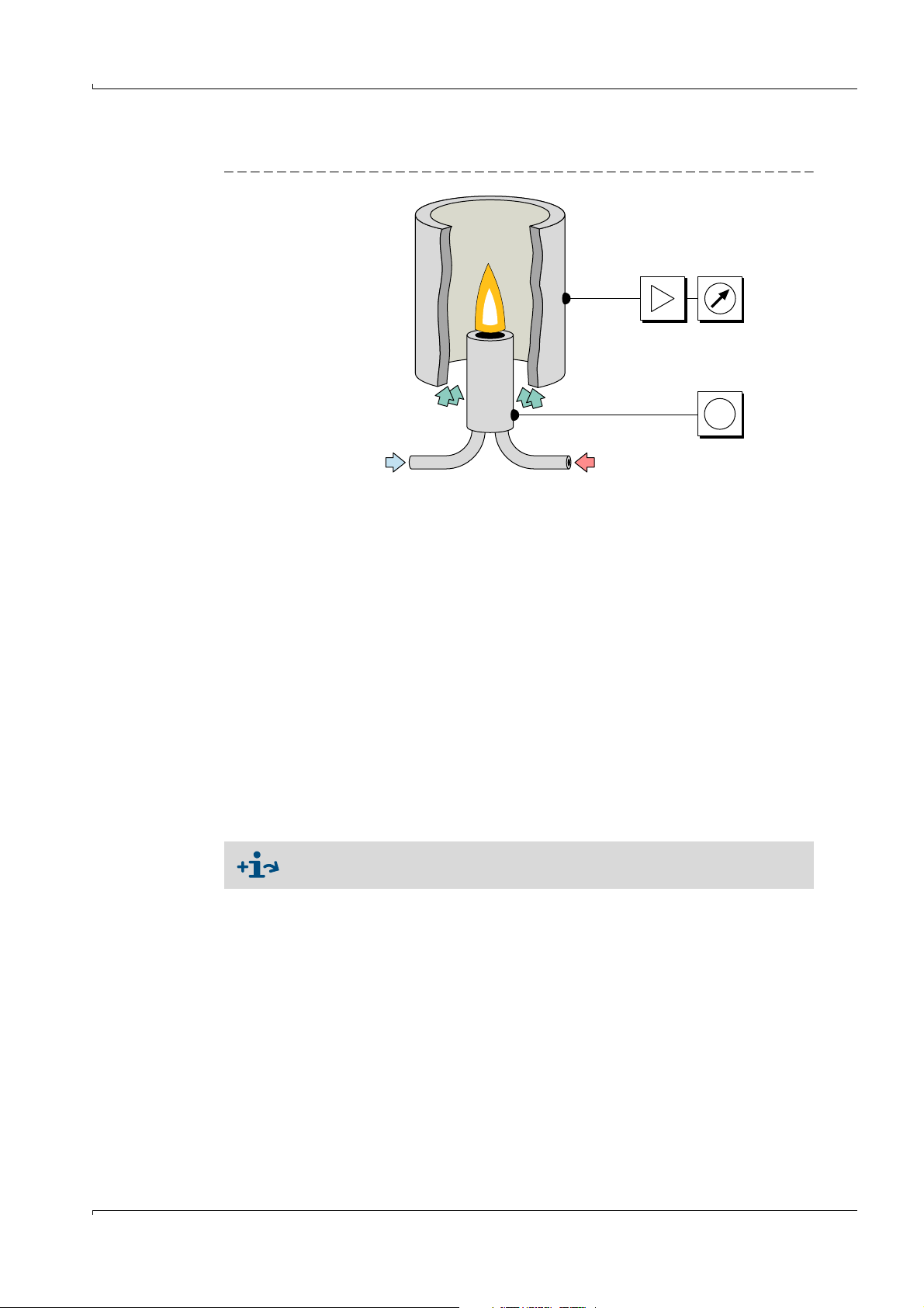
U=
Sample gas Fuel gas
Combustion air (instrument air)
2.2 Measuring principle
Fig. 1 Measuring principle
The EuroFID3010 Inline UEG uses a flame ionization detector (FID) to measure
hydrocarbons. A hydrogen flame burns in an electric field in the FID, fed by fuel gas and
combustion air. The sample gas is routed into this flame. The hydrocarbons contained in
the sample gas are split, and the resulting CH fragments are ionized. A stream of ions forms
in the electric field and this electrical current is measured.
2.3 Device overview
Device modules
The EuroFID3010 Inline UEG consists of 4 device modules:
● Analyzer unit:
– Analyzer (electronics, pneumatics, FID)
– Sampling probe
● Operating unit: Contains the electronic control unit, display and controls
● Terminal box: Interface between the operating unit and the analyzer
Provides the supply voltage for detector heating and the analyzer electronics
● V2 terminal module: Module with analog and digital inputs and outputs
Description of the device modules → p. 21, §2.4
Subject to change without notice
EuroFID3010 Inline UEG · Operating Instructions · 8016307/YL25/V 2-2/2018-04 · © SICK AG 19
Page 20
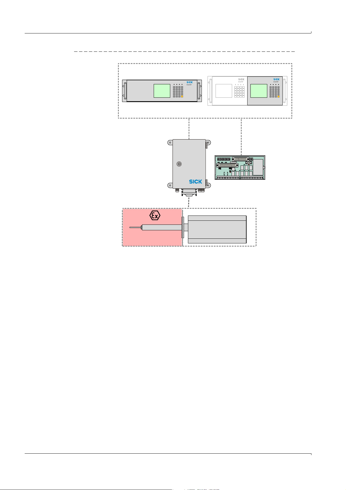
Fig. 2 EuroFID3010 Inline UEG device modules (overview)
R1R2
Analyzer unit
19” rack type operating unit ½-19” rack type operating unit
Terminal box
V2 terminal module
Explosionrisk zone
Product description
20 EuroFID3010 Inline UEG · Operating Instructions · 8016307/YL25/V 2-2/2018-04 · © SICK AG
Subject to change without notice
Page 21
Product description
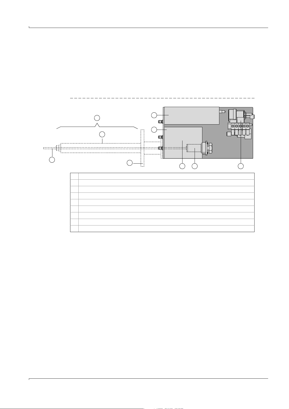
1
2
3 4 5
7
6
8
9
2.4 Device modules
2.4.1 Analyzer unit
The flange, sampling probe and analyzer are a single unit.
The analyzer unit is mounted with the flange directly in the process.
The outer housing protects the measuring system.
Optional: fan.
Optional: weatherproof cover.
Fig. 3 Analyzer unit
2.4.1.1
1 Electronics
2 Sensor block (heated)
3Ejector pump
4 Sample gas filter
5 Pneumatics (pressure regulator, flow controller, solenoid valve)
6 Sampling probe
7Thermal probe
8 Probe tube
9Flange
Sample gas filter
● The sample gas filter filters particles from the sample gas.
● Soiling of the filter is monitored.
If the filter is soiled, the error message “Service requirement” is displayed.
Filter change: → p. 134, §14.5
Subject to change without notice
EuroFID3010 Inline UEG · Operating Instructions · 8016307/YL25/V 2-2/2018-04 · © SICK AG 21
Page 22

2.4.2 Operating unit
Types
● 19” type – for installation in 19” racks (3 RU) (→ p. 50, § 6.2)
● ½-19” type – for installation in 19” racks (4 RU) (→ p. 50, § 6.3)
Elements
● Operating elements
– Display for measurements
–Keypad
– LEDs (indicator lights)
● V2 terminal module connection (→ p. 53, §7)
● AC power supply (→ p. 51, § 6.4)
● Optional: Electronic card for the “flow barrier” option.
2.4.3 Terminal box
● Voltage supply for the analyzer
● Connection for the housing fan
● Connection for the solenoid valve, flow barrier
Product description
2.4.4 V2 terminal module
● Analog outputs
– Measured value
– Reference value
● Digital outputs
–Alarm
–Status
● Digital inputs
–Calibration control
– Maintenance block
– Malfunction, gas supply
22 EuroFID3010 Inline UEG · Operating Instructions · 8016307/YL25/V 2-2/2018-04 · © SICK AG
Subject to change without notice
Page 23

Project planning
EuroFID3010 Inline UEG
3 Project planning
Included in delivery
Overview of installation
Operating materials
Gas supply
Exhaust gas venting
Subject to change without notice
EuroFID3010 Inline UEG · Operating Instructions · 8016307/YL25/V 2-2/2018-04 · © SICK AG 23
Page 24

3.1 Included in delivery
● 1 analyzer unit – with 3-m connection cable to the terminal box
● 1 operating unit
● 1 terminal box with 6-m connection cable to the operating unit
● 1 AC power supply cord, 3 m long – with plug to connect to the terminal box
● 4 flange screws + 1 flange gasket
● V2 terminal module
● 5-m cable to connect the operating unit to the V2 terminal module
● Declaration of clearance
● 1 test log
● 1 set of Operating Instructions
Available accessories (optional)
● Mounting flange
● Weatherproof cover
● Shut-off fitting (for gas supply)
● Solenoid valve (for the “flow barrier” option)
Project planning
3.2 Information about project planning and installation
● EN 60079-29-2: Explosive Atmospheres - Part 29-2: Gas detectors - Selection,
installation, use and maintenance of detectors for flammable gases and oxygen
● Pamphlet T 023 (BGI 518) “Gaswarneinrichtungen für den Explosionsschutz - Einsatz
und Betrieb” (Gas warning systems to protect against explosion) from the Employers'
Liability Insurance Association of the German Chemical Industry must be observed.
24 EuroFID3010 Inline UEG · Operating Instructions · 8016307/YL25/V 2-2/2018-04 · © SICK AG
Subject to change without notice
Page 25
Project planning
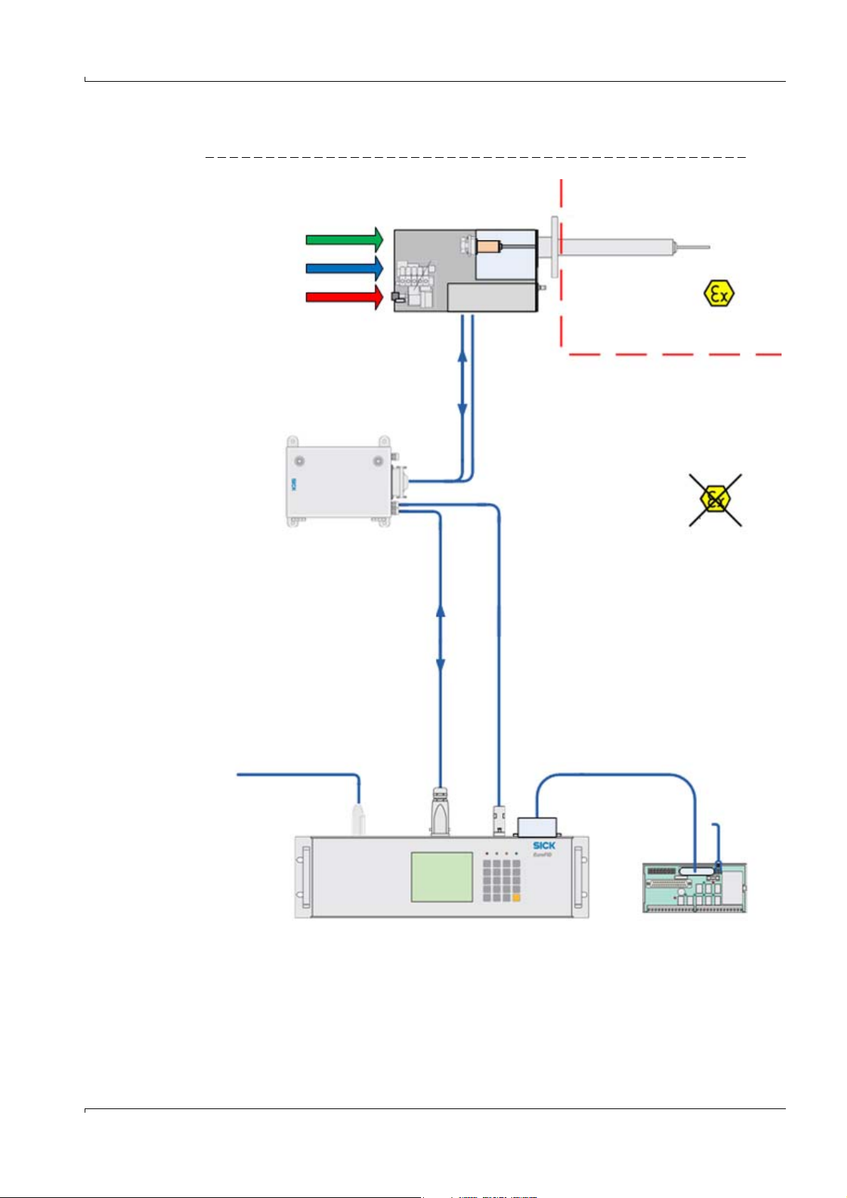
Analyzer unit
Test gas
Instrument air
Fuel gas
ZONE 1
ZONE
Terminal box
Power voltage
115 / 230 V
Operating unit
I/O module
24 VDC
Data
Data
115 / 230 V
115 / 230 V
3.3 Overview of installation work
Fig. 4 Overview of installation
Subject to change without notice
EuroFID3010 Inline UEG · Operating Instructions · 8016307/YL25/V 2-2/2018-04 · © SICK AG 25
Page 26
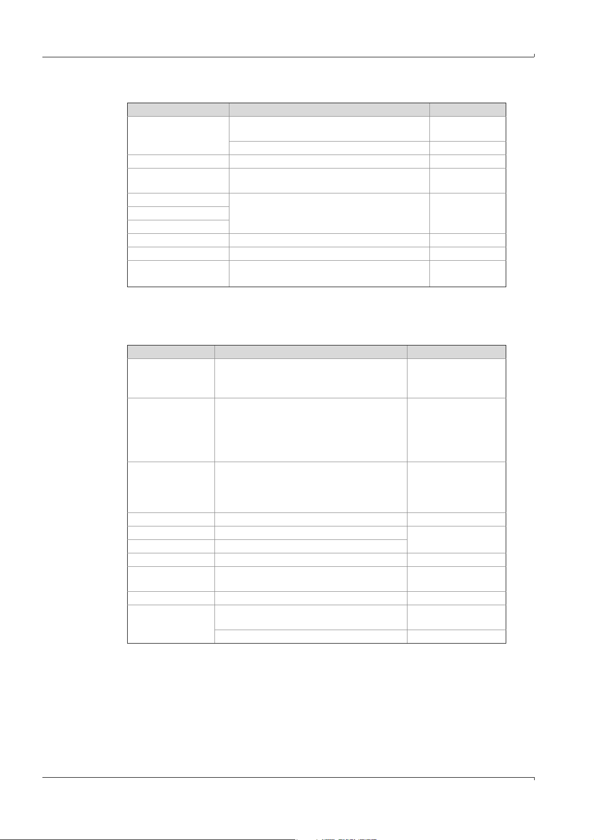
3.3.1 Required resources (overview)
Required resource Notes, requirements Information
Instrument air – Continuous supply of technical
compressed air to the analyzer unit
– Free of hydrocarbons → p. 166, § 16.8.1
Fuel gas – Continuous supply to the analyzer unit → p. 30, §3.4.4
Leakage detection
system
[1]
– To warn about explosion risk in the event of
H
leakage
2
Pressure reducer – For instrument air
[1]
Pressure monitor
Shut-off valves
[1]
–For fuel gas
–Test gas
Test gas – Only during calibration → p. 112, § 12.4.2
Exhaust gas line – Outlet → p. 31, § 3.5
Voltage supply – AC power connection at the operating unit
– Terminal module
[1] Recommended
3.3.2 Mechanical installations (overview)
The following system components must be installed:
Component Installation site, requirements Detailed information
Supply line for
instrument air
– Suitable pressure reducer
– Gas line to the analyzer unit
– Oil-free installation
Compressed gas
cylinder(s) for fuel
gas
– At a suitable location that meets the
safety requirements
– Suitable pressure reducer
– Gas line to the analyzer unit
– Leakage detection system
Compressed gas
cylinder(s) for test
gas
– At a suitable location that meets the
safety requirements
– Suitable pressure reducer
– Gas line to the analyzer unit
Analyzer unit – Ina mounting flange → p. 34, § 4.2
Shut-off fitting – Near the analyzer unit
Solenoid valve
Terminal box – Near the
Operating unit – Near the
[4]
– On the analyzer unit
[5]
analyzer unit
[6]
terminal box or the analyzer
unit
V2 terminal module – Near the operating unit
Electrical
connections
–Analyzer unit (→ terminal box) → analyzer
unit
–Signal connections as required → p. 52, § 6.5
[1] High-purity copper or stainless steel wiring
[2] (Recommended.)
[3] Pre-assembled shut-off fitting available as an accessory.
[4] Only for devices with the “flow barrier” option.
[5] Standard length of the connection cable: 3 m
[6] Standard length of the connection cable: 6 m (max. 500 m).
[7] Standard length of the connection cable: 5 m
[3]
[7]
Project planning
→ p. 29, § 3.4.3
→ p. 30, § 3.4.4
→ p. 29, § 3.4.3
→ p. 30, § 3.4.4
→ p. 51, § 6.4
→ p. 63, § 7.6
→ p. 29, § 3.4.3
[1]
→ p. 30, § 3.4.4
[1]
[2]
→ p. 30, § 3.4.4
[1]
→ p. 39, § 4.2.4
→ p. 43, § 5
→ p. 49, § 6
–
→ p. 33, § 4
Subject to change without notice
26 EuroFID3010 Inline UEG · Operating Instructions · 8016307/YL25/V 2-2/2018-04 · © SICK AG
Page 27

Project planning
3.3.3 AC power connection (overview)
● AC power for the analyzer is supplied via the operating unit (→ p. 51, §6.4).
● Recommended: Install a separate, external all-pole-disconnecting AC power switch and
fuses near the operating unit (max. power input of the EuroFID3010 Inline UEG →
Technical Data) (→ p. 51, § 6.4.1).
The terminal box receives AC voltage from the operating unit and in turn
supplies the analyzer unit with operating voltage.
Subject to change without notice
EuroFID3010 Inline UEG · Operating Instructions · 8016307/YL25/V 2-2/2018-04 · © SICK AG 27
Page 28
3.4 Supply of operational gases
3 bar
H2/He
Fuelgas
3 bar
Kalibriergas
Calibr.gas
3 bar
Instr.Luft
Instr. air
Auspuff
Outlet
Fuel gas
Calibration gas
Instrument air
Fig. 5 Gas connections
The analysis component requires 3 gases to operate:
● Fuel gas
● Calibration gas
● Instrument air
The gas lines must be able to be shut off for deinstallation.
▸
Include shut-off valves in the operating gas lines (→ p. 170, §16.11.3)
Project planning
3.4.1 Screw fittings for the gas connections
● Standard: Clamping ring screw connections for tubes with a 6-mm outside diameter,
brand name “Swagelok.”
● When the screw connections are removed, inside threads are available:
– All gas connections: inside threads G1/8”
● Connections for the supply and test gases: G1/8 inside thread
● Male screw joints: metal with G1/8 thread (DIN/ISO228/1) and O-rings/seals rings.
28 EuroFID3010 Inline UEG · Operating Instructions · 8016307/YL25/V 2-2/2018-04 · © SICK AG
Subject to change without notice
Page 29
Project planning
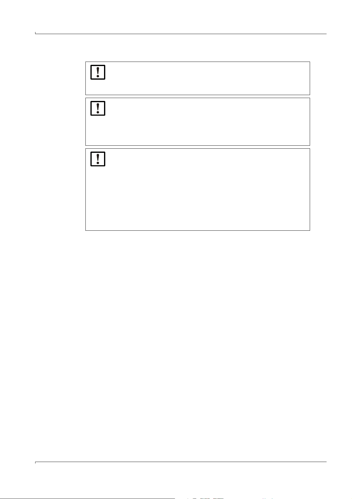
3.4.2 General information on the gas supply
NOTICE:
The user is responsible for ensuring that the gas supply is leak-tight.
▸
Check the leak tightness of the gas lines after installation.
▸
Leak detection spray, sensor for combustible gases.
NOTICE:
Contaminated operating gases can falsify the measured values and damage
the analyzer unit.
▸
Make sure that the gas lines are clean:
– Free of particles (dust, shavings)
– Free of hydrocarbons (grease, oil, solvents).
NOTICE: Observe the reaction time of the FID during a hydrogen supply
failure
During a hydrogen supply failure, the flame of the FID keeps burning for some
time until it goes out completely.
It is possible that the measured value of the FID does not correspond to the
true value during this time.
The reaction time can be up to 50 seconds depending on the version of the
equipment.
▸
In order to monitor for a hydrogen supply failure, monitor the inlet pressure
of the fuel gas using a pressure controller, which emits an electric signal at
a certain minimum pressure (e.g. < 3 bar).
3.4.3 Connecting instrument air
The EuroFID3010 Inline UEG requires hydrocarbon-free instrument air to operate
(Specifications → p. 166, §16.8.1).
Instrument air is used for the following purposes:
– As propellant air for the ejector pump
–Sample gas dilution
–As combustion air
–As control air
– As zero gas for calibration
▸
Install a continuous supply of instrument air at the gas connection labeled “Instr.air.”
Subject to change without notice
EuroFID3010 Inline UEG · Operating Instructions · 8016307/YL25/V 2-2/2018-04 · © SICK AG 29
Page 30
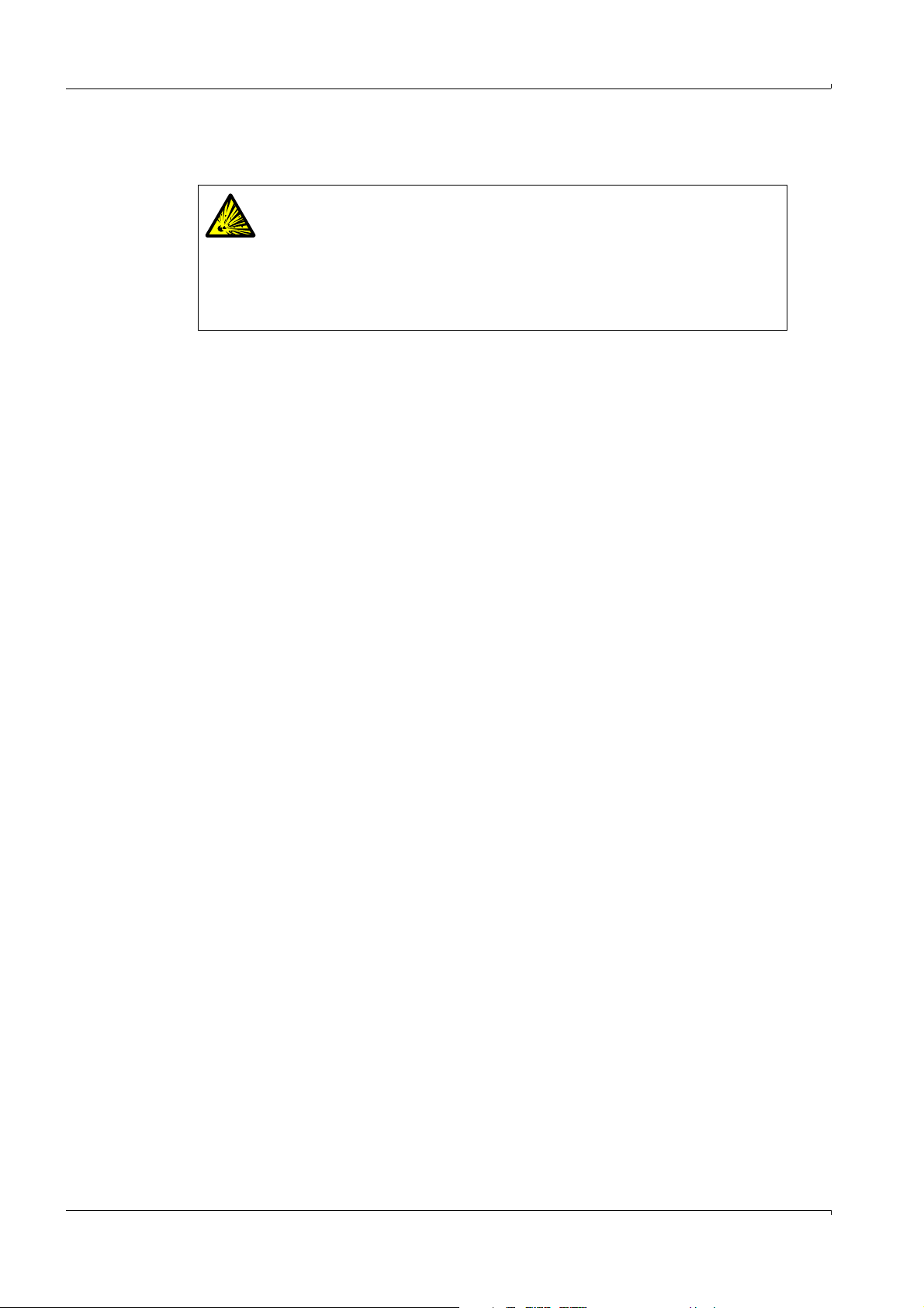
3.4.4 Connecting fuel gas
▸
Install a continuous supply of fuel gas at the gas connection labeled “Fuel gas.”
WARNING: Risk of explosion if fuel gas line leaks.
The fuel gas is H
A leak in the fuel gas line may lead to an explosion.
▸
Implement safety precautions to prevent explosion.
– Install a volume flow limiter in the fuel gas supply line.
– Install a leak detector on the fuel gas supply line to emit a signal when
H
is discharged.
2
▸
Monitor the cylinder pressure of the fuel gas with a pressure monitor which emits an
electrical signal below a certain minimum pressure (e.g. < 3 bar).
Connect the signal from the pressure monitor to the digital input labeled “Fault Gas Supply”
(→ p. 60, §7.4).
3.4.5 Connecting the calibration gas (“span gas”)
▸
Install a continuous supply of calibration gas to the gas connection labeled “Calibr.gas.”
▸
Recommendation: Monitor the cylinder pressure of the calibration gas with a pressure
monitor which emits an electric signal at a certain minimum pressure (e.g. < 10 bar).
Connect the signal from the pressure monitor to the digital input labeled “Fault Gas Supply”
(→ p. 60, §7.4).
.
2
Project planning
3.4.6 Information on connecting a cylinder pressure monitor
A pressure monitor must be connected to terminals X20.13+X20.14 of the V2 terminal
module. When two pressure monitors are used, their contacts must be connected in series
and can only be processed as a composite signal.
30 EuroFID3010 Inline UEG · Operating Instructions · 8016307/YL25/V 2-2/2018-04 · © SICK AG
Subject to change without notice
Page 31
Project planning
1
2
3
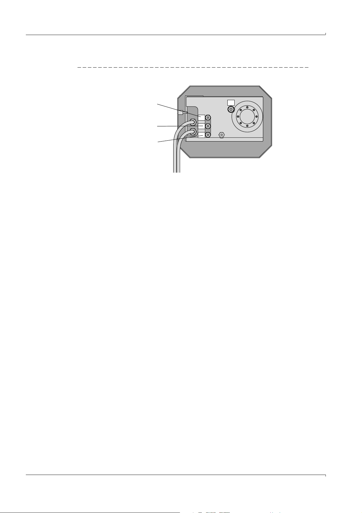
3.5 Exhaust gas lines
Fig. 6 Exhaust gas connections
1Gas outlet “Outlet”
2 Gas outlet “Bypass”
3 Gas inlet (probe tube)
3.5.1 Connecting the “Outlet” gas outlet
The exhaust gas from the combustion chamber exits at “Outlet”.
Important: The exhaust gas contains water vapor (condensation).
▸
Use corrosion-resistant tube material for the exhaust gas line (e.g. stainless steel or
Teflon tubes).
▸
Inside diameter: 4 mm.
▸
Max. length: 3 m.
▸
Install the exhaust gas lines at a continuous downward angle so that condensed liquid
can reliably drain away.
▸
Route the exhaust gas line to a collection point:
– Atmospheric pressure
– No pronounced pressure fluctuations.
WARNING: Risk of explosion
The exhaust gas from the “outlet”
▸
may not be returned to the process;
▸
must be drained off to a non-potentially explosive atmosphere in a safe
manner.
NOTICE:
Condensate is generated in the exhaust gas line.
▸
Arrange the exhaust lines so that they cannot become obstructed by
condensing liquid.
▸
Protect exhaust gas lines against freezing.
CAUTION: Contaminants in the condensate
Condensate from the exhaust gas contains substances from the sample gas.
These substances may be chemically corrosive and/or must be disposed of
separately.
▸
If necessary: Collect the condensate from the exhaust line and dispose of
Subject to change without notice
EuroFID3010 Inline UEG · Operating Instructions · 8016307/YL25/V 2-2/2018-04 · © SICK AG 31
properly.
Page 32

NOTICE:
Backpressure and pressure fluctuations at the exhaust gas connection
– Can affect the measured values
– Can prevent ignition of the FID flame.
▸
If the EuroFID3010 Inline UEG is installed in a ventilated or air-conditioned
enclosed area and the ventilation/air conditioning system in this area can
generate overpressure or pressure fluctuations: Do not allow the exhaust
gas line to discharge into this area.
3.5.2 Gas outlet “Bypass”
Excess gas from the ejector pump (a mixture of instrument air and sample gas) exits at the
“Bypass”
and is returned to the process via the thermal probe.
3.6 Sample gas supply
For sample gas requirements, refer to Technical data (→ p. 167, § 16.9)
Sample gas supply → p. 38, §4.2.3
Project planning
32 EuroFID3010 Inline UEG · Operating Instructions · 8016307/YL25/V 2-2/2018-04 · © SICK AG
Subject to change without notice
Page 33

Installing the analyzer unit
EuroFID3010 Inline UEG
4 Installing the analyzer unit
Mechanical installation
Gas connections
Electrical connections
Subject to change without notice
EuroFID3010 Inline UEG · Operating Instructions · 8016307/YL25/V 2-2/2018-04 · © SICK AG 33
Page 34

4.1 Preparing for Installation
WARNING: Risk of fire when measuring combustible gases
Feeding ignitable gases or gas mixtures is not allowed.
No special requirements exist when measuring combustible gases when the
sample gas concentration does not exceed 25% of the lower explosion limit
(LEL).
Meet the following requirements when exceeding the 25% LEL limit:
▸
Check the leak tightness of the hydrogen feed line to the equipment at
regular intervals.
▸
Observe the correct pressure for the hydrogen feed.
● Compare the information on the type plate with the operating conditions.
● Check ambient temperature (refer to “Technical data”).
● Make sure that the classification temperature is below the ignition temperature of the
combustible gases.
● Perform work on the EuroFID3010 Inline UEG in a non-explosive area only.
4.2 Installation
CAUTION: Risk of injury through incorrect lifting and carrying the equipment
Injuries can occur due to the weight and projecting enclosure parts when the
equipment tips over or drops. Observe the following information to avoid such
accidents:
▸
Do not use protruding parts on the enclosure to carry the equipment (apart
from the wall fixture or carrying grips).
▸
Never lift the equipment using the open equipment door.
▸
Consider the equipment weight before lifting.
▸
Observe the regulations for protective clothing (e.g., safety shoes, non-slip
gloves)
▸
Grip underneath the equipment when possible to carry it safely.
▸
Use a hoist or transport equipment as an option.
▸
Use the help of a second person when necessary.
▸
Secure the equipment during transport.
▸
Before transporting, ensure obstacles that could cause falls or collisions
are cleared away.
Installing the analyzer unit
CAUTION: Accident risk through inadequate fastening of the device
▸
Consider the device weight specifications when planning the mounting
supports.
▸
Check the load capacity/condition of the wall/rack on/in which the device
is to be installed.
● The installation location must be free of oscillations and vibrations.
NOTICE: Absence of vibration
In the frequency range from 10-150 Hz, vibratory stress may not exceed
0.2 g (= 1.96 m/s²).
● The ambient air must be free of dust and other impurities that could corrode materials
in the device.
34 EuroFID3010 Inline UEG · Operating Instructions · 8016307/YL25/V 2-2/2018-04 · © SICK AG
Subject to change without notice
Page 35

Installing the analyzer unit
Sampling probe
Fig. 7 Lifting points
● A high-temperature mounting flange is available for applications with process
temperatures above 300°C.
NOTICE:
The sampling probe is equipped with a glass vacuum tube,
which is fragile.
▸
Make sure no force is applied to the sampling probe when handling the
analyzer unit.
▸
Lift the analyzer unit by the housing only (→ Fig. 7).
Subject to change without notice
EuroFID3010 Inline UEG · Operating Instructions · 8016307/YL25/V 2-2/2018-04 · © SICK AG 35
Page 36

4.2.1 Clearance for the analyzer unit
Interior wall
Exterior wall
Thickness of insulation in the process
equipment
Fig. 8 Clearance for the analyzer unit
Installing the analyzer unit
36 EuroFID3010 Inline UEG · Operating Instructions · 8016307/YL25/V 2-2/2018-04 · © SICK AG
Subject to change without notice
Page 37

Installing the analyzer unit
Thermal probe
Mounting flange
Sealing ring
Bolt M12 x 60
Interior wall of
process
Insulation Exterior wall of
process
4.2.2 Preparing to install the analyzer unit
The analyzer unit is mounted at the process wall according to the following diagram.
Fig. 9 Installation overview
● A mounting flange is required to attach the analyzer unit.
● Permissible angle of the analyzer unit: ±35° to the horizontal.
The user is responsible for installing the flange.
● Weight of the analyzer unit: 25 kg.
Supporting struts may need to be added to ensure the mechanical stability of the
analyzer unit.
Dimensions of the sampling probe → p. 158, Fig. 33
Fig. 10 Mounting flange heat decoupling unit
Subject to change without notice
EuroFID3010 Inline UEG · Operating Instructions · 8016307/YL25/V 2-2/2018-04 · © SICK AG 37
Page 38

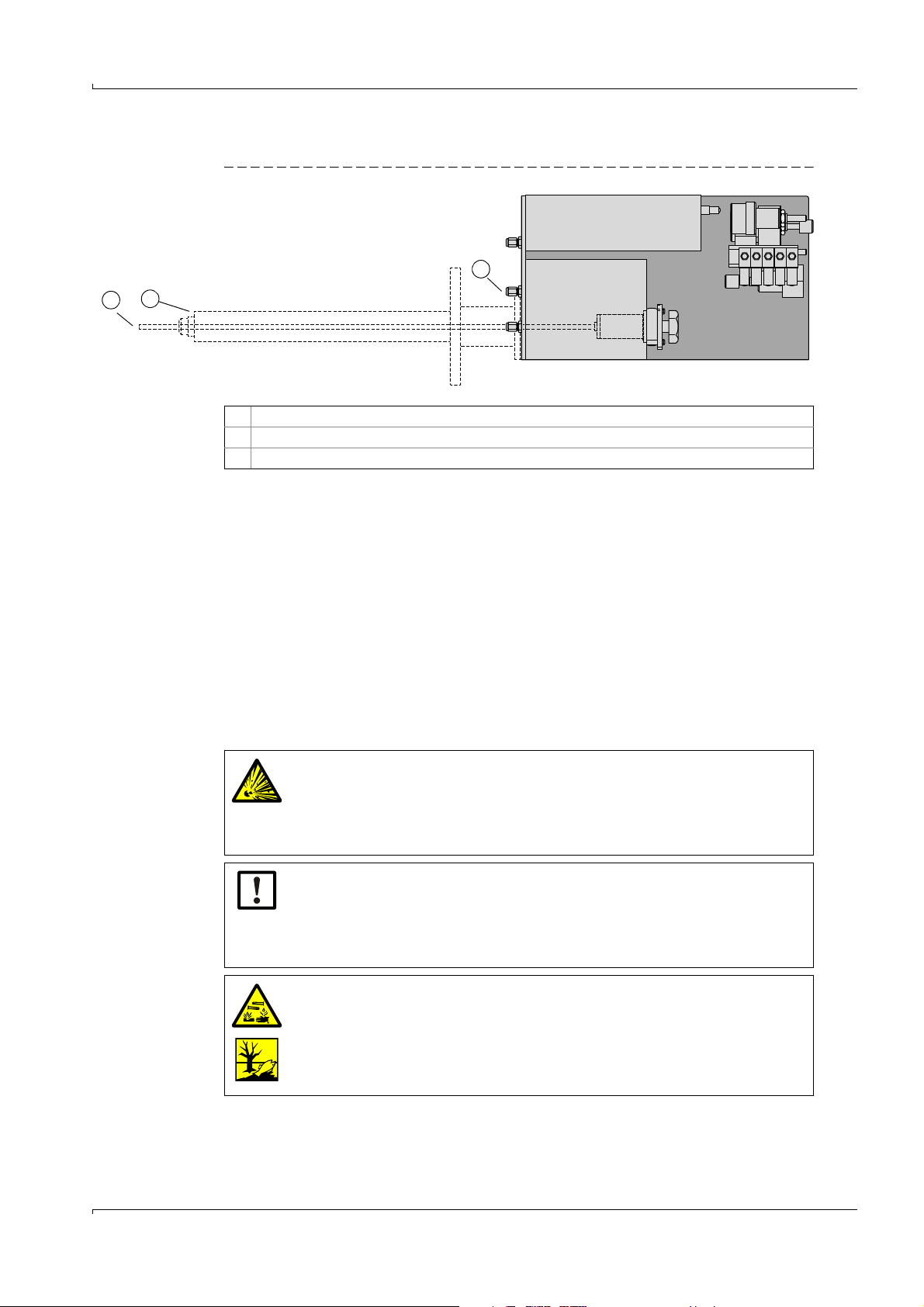
4.2.3 Installing the analyzer unit on the flange
Sampling
probe
Sample gas
Probe tube
Bypass outlet
WARNING: Hazard from process gases
For processes with overpressure, hot or toxic gases may escape when the
sampling point is opened.
▸
Undertake suitable safety measures.
NOTICE:
▸
2 persons should install the analyzer unit on the flange.
● The probe tube must freely protrude into the process gas stream.
WARNING: Incorrect measured values due to improper installation
If the gas inlet is too short, the EuroFID3010 Inline UEG draws in the exhaust
gas, which dilutes the sample gas as a result.
▸
Do not shorten the probe tube.
The bypass exhaust gas stream emerges from the thermal probe of the
sampling probe.
▸
Do not install any components so close to the sampling probe that the
bypass exhaust gas stream could be drawn in again by the probe tube.
Fig. 11 Exhaust gas exit
Installing the analyzer unit
Attachment
1 Position a flange seal between the mounting flange and the flange of the analyzer unit.
▸
If the analyzer unit is used for hot processes (> 300°C): Use the heat insulation
flange instead of the flange seal (→ p. 169, Fig. 39).
2 Carefully insert the sampling probe into the flange tube.
3 Connect the flange with the supplied screw fittings.
38 EuroFID3010 Inline UEG · Operating Instructions · 8016307/YL25/V 2-2/2018-04 · © SICK AG
Subject to change without notice
Page 39
Installing the analyzer unit
4.2.4 Gas connections
Gas connection Gas Installation work
Instr. air
Instr. air
Fuel gas
Fuel gas
Calibration gas
Calibr. gas
Outlet Exhaust gas
WARNING: Risk of explosion if gas connections are mixed up
● Observe the labels on the gas inlets.
Recommendation: To be able to stop the gas supply to the device manually,
▸
install a shut-off valve in the gas feed.
The shut-off valve is available as an option (→ p. 170, § 16.11.3).
Instrument
air
Fuel gas
Span gas
▸
Observe the information on instrument air (→ p. 29,
§3.4.3).
▸
Connect the instrument air supply to the “Instr.air”
gas connection.
On devices with the “flow barrier” option:
▸
Also connect the instrument air supply to a gas
connection of the solenoid valve.
▸
Connect the other gas connection of the solenoid
valve to the “flow barrier” gas connection.
▸
Observe the information on fuel gas (→ p. 30, § 3.4.4).
▸
Connect the fuel gas supply to the “Fuel gas” gas
connection.
▸
Supply suitable span gas.
▸
Observe the information on span gas supply
(→ p. 30, §3.4.5).
▸
Connect the span gas supply to the “Calibr. gas” gas
connection.
▸
Connect an exhaust gas line to the “Outlet”
connection. Suitable material: Corrosion-resistant
hose with an inside diameter of 6 mm.
▸
Observe the information on installing the exhaust
gas connections (→ p. 31, § 3.5).
Subject to change without notice
EuroFID3010 Inline UEG · Operating Instructions · 8016307/YL25/V 2-2/2018-04 · © SICK AG 39
Page 40
4.3 Electrical connections
4.3.1 Electrical compliance
4.3.1.1 Electrical safety through disconnector switches properly installed
WARNING: Endangerment of electrical safety during installation and
maintenance work when the power supply is not switched off
An electrical accident can occur during installation and maintenance work
when the power supply to the device and/or lines is not switched off using a
disconnector switch/circuit breaker.
▸
Ensure that the power supply of the device can be switched off in
accordance with DIN EN 61010 using a disconnector switch/circuit
breaker.
▸
Make sure the disconnector switch is easily accessible.
▸
An additional disconnecting device is mandatory when the disconnector
switch is difficult to access or cannot be accessed when connecting the
equipment after installation.
▸
After completion of the work or for test purposes, the power supply may only
be activated again by authorized personnel complying with the safety
regulations.
Installing the analyzer unit
4.3.1.2 Electrical safety through lines with correct rating
WARNING: Endangerment of electrical safety through power cable with
incorrect rating
When a removable power cable is used, electrical accidents can occur when
the specifications are not fully observed.
▸
Always observe the exact specifications in the Operating Instructions
(Technical Data Section) when replacing a removable power cable.
4.3.1.3 Grounding the equipment
CAUTION: Device damage through incorrect or missing grounding.
During installation and maintenance work, it must be ensured that the
protective grounding to the devices and/or lines involved is effective in
accordance with EN 61010-1.
40 EuroFID3010 Inline UEG · Operating Instructions · 8016307/YL25/V 2-2/2018-04 · © SICK AG
Subject to change without notice
Page 41
Installing the analyzer unit
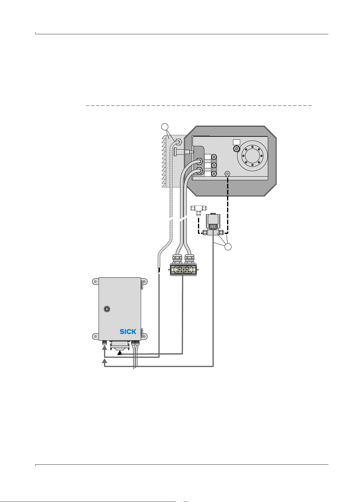
A Only with “fan” option
B Solenoid valve – only with “flow barrier” option
3 bar
H2/He
Fuelgas
3 bar
Kalibriergas
Calibr.gas
3 bar
Instr.Luft
Instr. air
Auspuff
Outlet
A
B
Terminal box
Analyzer
4.3.2 Procedure
▸
Connect the plug connector to the terminal box with the double cable.
▸
On devices with the “flow barrier” option: Connect the solenoid valve to the terminal box
(→ p. 44, § 5.2).
▸
On devices with the “Fan” option: Connect the fan’s cable to 24 VDC in the terminal box
(→ p. 44, § 5.2).
Fig. 12 Analyzer: connections
Subject to change without notice
EuroFID3010 Inline UEG · Operating Instructions · 8016307/YL25/V 2-2/2018-04 · © SICK AG 41
Page 42

Installing the analyzer unit
42 EuroFID3010 Inline UEG · Operating Instructions · 8016307/YL25/V 2-2/2018-04 · © SICK AG
Subject to change without notice
Page 43

Installing the terminal box
EuroFID3010 Inline UEG
5 Installing the terminal box
Assembly
Electrical connections
Subject to change without notice
EuroFID3010 Inline UEG · Operating Instructions · 8016307/YL25/V 2-2/2018-04 · © SICK AG 43
Page 44

5.1 Installing the terminal box
▸
Install the terminal box near the analyzer unit (taking the cable length into account).
▸
Install it so that the that the cable inlets are on the underside of the terminal box if
possible.
5.2 Electrical connections of the terminal box
CAUTION: Damage/malfunction due to improper AC power connection
The terminal box is supplied with AC voltage directly from the operating unit.
▸
AC voltage for the terminal box: refer to type plate on the terminal box.
▸
The protective conductors (PE) must always be connected.
Power voltage circuit breaker
▸
Install a power voltage circuit breaker near the terminal box to switch the main power
supply of the terminal box on and off.
Connection cable of the analyzer unit
▸
Connect the two connection cables of the analyzer unit to the corresponding plug
connectors of the terminal box (→ p. 45, Fig. 13).
Customized connection cables
▸
For customized connection cables, use the following cable material:
Installing the terminal box
Connection Wire cross-section Type Name Part no.
Analyzer assembly
terminal box
Data cable for
data line
Data cable for
data line
[1] Carries AC line voltage.
▸
Install wiring according to Fig. 14 (→ p. 46).
Connection for flow barrier
▸
Connect the solenoid valve of the flow barrier to the connections labeled VALVE
(0 V/+24 V) (X18/X19).
Connection for housing fan
▸
Connect the cable of the housing fan to a 0 V/+24 V connection (X20/X21 or X36/
X37).
[1]
3 x 1.5 mm2 Shielded
5 x 1.5 mm
4 x 2 x 0.25 mm
4-pole x 0.34 mm
2
Shielded
2
2
AWG22 6030048
LIYC2Y
(TP)
Ölflex Control
TMCY
Ölflex Control
TMCY
6048807
6048809
44 EuroFID3010 Inline UEG · Operating Instructions · 8016307/YL25/V 2-2/2018-04 · © SICK AG
Subject to change without notice
Page 45

42VAC
PE
PE
0V
+24V
0V
0V
Valve (+24V)
+24V
X17_19 X36_37 X20_21 X12_14
X10_11
max. 500 m
A B
A
B
A only with housing fan option
B only with flow barrier option
Analyzer unit
Terminal box
Solenoid valve
Operating unit
max. 6 m
Installing the terminal box
Fig. 13 Terminal box: Connections
Subject to change without notice
EuroFID3010 Inline UEG · Operating Instructions · 8016307/YL25/V 2-2/2018-04 · © SICK AG 45
Page 46

Fig. 14 Terminal box: Wiring of the connection cables
Data cable in
Datenleitung
X1.1
X1.2
X1.3
X1.4
123
PE
X28
X27
X26
X25
X24
X23
X22
X15
X16
123456789
L1
N
PE
Reset
Reset
Data out
Data out
Data in
Data in
24 VDC
24 VDC
sworswrtsw
ge
br
sw
black
orange
black
red
black
yellow
brown
black
max. 500 m (RS422)
Operating unit
Terminal box
Installing the terminal box
Analyzer Assembly
Terminalbox
AC 115V/230V
46 EuroFID3010 Inline UEG · Operating Instructions · 8016307/YL25/V 2-2/2018-04 · © SICK AG
Subject to change without notice
Page 47

Installing the terminal box
6036664 ring core 6.0 - 7.5
6036662 ring core 8.5 - 10.5
Voltage supply
Analyzer
42 VAC
Data line
Analyzer
Operating unit
Data line
Voltage supply
Fig. 15 Terminal box
A ferrite ring core must be attached to both the AC power line and the data line (see
diagram above).
Cable Conductor Terminal Cable Color Terminal
AC power
cable
L1 X1-1 Data cable Brown 15
N X1-2 Black 16
PE X1-3 Shielding 22
Yellow 23
Black 24
Red 25
Black 26
Subject to change without notice
Orange 27
Black 28
EuroFID3010 Inline UEG · Operating Instructions · 8016307/YL25/V 2-2/2018-04 · © SICK AG 47
Page 48

Installing the terminal box
48 EuroFID3010 Inline UEG · Operating Instructions · 8016307/YL25/V 2-2/2018-04 · © SICK AG
Subject to change without notice
Page 49

Installing the operating unit
EuroFID3010 Inline UEG
6 Installing the operating unit
Installation
Electrical connections
Signal connections
Subject to change without notice
EuroFID3010 Inline UEG · Operating Instructions · 8016307/YL25/V 2-2/2018-04 · © SICK AG 49
Page 50

6.1 Installing the operating unit
Housing dimensions and space requirements:
– Operating unit, 19” rack type → p. 160, Fig. 35
– Operating unit, ½-19” rack type → p. 161, Fig. 36
● Do not obstruct the fan openings (rear of unit).
● Installation location must be free of vibrations.
6.2 Installing the 19” rack type operating unit
▸
Install the 19” operating unit in the normal manner in a 19” rack or corresponding
enclosure.
▸
Use the rack rails.
NOTICE:
Do not secure the housing by the front panel alone.
▸
Use the rails that support the housing.
6.3 Installing the operating unit, ½-19” rack type
▸
Install the ½-19” operating unit into a 19” rack (4 RU).
Installing the operating unit
Fig. 16 Operating unit: Installing the ½-19” rack type operating unit
50 EuroFID3010 Inline UEG · Operating Instructions · 8016307/YL25/V 2-2/2018-04 · © SICK AG
Subject to change without notice
Page 51

Installing the operating unit
I / 0
IEC/CEE-22
L/N/PE
AC power
Fuses
4A slow blow 250V
UL/CSA standard
6.4 AC power connection of the operating unit
During installation and maintenance, make sure the electrical supply to
affected devices or lines can be turned off via a disconnector switch/circuit
breaker in accordance with EN 61010-1.
The electrical supply may only be reactivated by staff performing the
installation or maintenance, after completing the work or for test purposes,
and taking safety regulations into consideration.
6.4.1 External AC power switch
If the AC power switch of the operating unit (→ Fig. 17) is not visible and accessible in the
operational state:
▸
Install an AC power supply disconnector switch near the operating unit to be able to turn
the AC power supply on and off.
6.4.2 Connecting the AC power cable
▸
Ensure that the supplied AC voltage corresponds to the information on the type plate of
the operating unit.
Only connect the operating unit to a voltage supply with these specifications.
Observe: When a 115 volt operating unit is connected to 230 V, serious
damage may occur. Only connect the operating unit to a voltage supply which is
equipped with a grounding conductor and only use the power cable delivered.
▸
Connect the AC power cable to the integrated connector on the rear of the operating
unit (→ Fig. 17).
▸
Connect the AC power cable to the AC power supply.
Fig. 17 AC power plug, AC power switch
AC power cable Part no.
AC power cord with IEC-320 male connector with
Subject to change without notice
grounding contact (230 V)
AC power cord with grounding contact for use in the USA
(115 V)
EuroFID3010 Inline UEG · Operating Instructions · 8016307/YL25/V 2-2/2018-04 · © SICK AG 51
6026779
6031563
Page 52

6.5 Signal connections
System
Not
used
RS232-C
Analog and Digital I/O
6.5.1 Overview of signal connections
Fig. 18 Operating unit: Plug connector for signal connections
Interfaces
● “System” and “RS 232C” are interfaces for the manufacturer to use internally for
testing and service purposes.
Installing the operating unit
Measured values and signals
The V2 terminal module is connected to the 37-pin D-sub connector labeled “Analog and
Digital I/O”
NOTICE:
Before signal connections are established (including with plug connections):
▸
Disconnect the EuroFID3010 Inline UEG and any connected devices from AC
power (i.e. switch off),
otherwise the internal electronics may be damaged.
52 EuroFID3010 Inline UEG · Operating Instructions · 8016307/YL25/V 2-2/2018-04 · © SICK AG
Subject to change without notice
Page 53

V2 terminal module
EuroFID3010 Inline UEG
7 V2 terminal module
Installation
Connection options
Configuration options
Subject to change without notice
EuroFID3010 Inline UEG · Operating Instructions · 8016307/YL25/V 2-2/2018-04 · © SICK AG 53
Page 54

7.1 Functional description
Fig. 19 V2 terminal module
V2 terminal module
The V2 terminal module is a plug-in module for standard mounting rails in switching
cabinets (dimensions → p. 171, 16.11.5).
The V2 terminal module contains:
● Analog outputs (→ p. 56, § 7.2):
– Measured value/reference value
● Digital outputs (→ p. 57, § 7.3)
– Main alarm/pre-alarm
– Status outputs
● Digital inputs (→ p. 60, §7.4)
–Calibration control
– Maintenance
The following can be connected to the V2 terminal module:
● Reset button to acknowledge the main alarm
● Service switch
● Indicator lights
● Button to check the indicator lights
Information
Update of the digital inputs and outputs and the analog outputs: 200 ms.
When no reset button is added, the main alarm can not be acknowledged and is
continuously activated.
54 EuroFID3010 Inline UEG · Operating Instructions · 8016307/YL25/V 2-2/2018-04 · © SICK AG
Subject to change without notice
Page 55
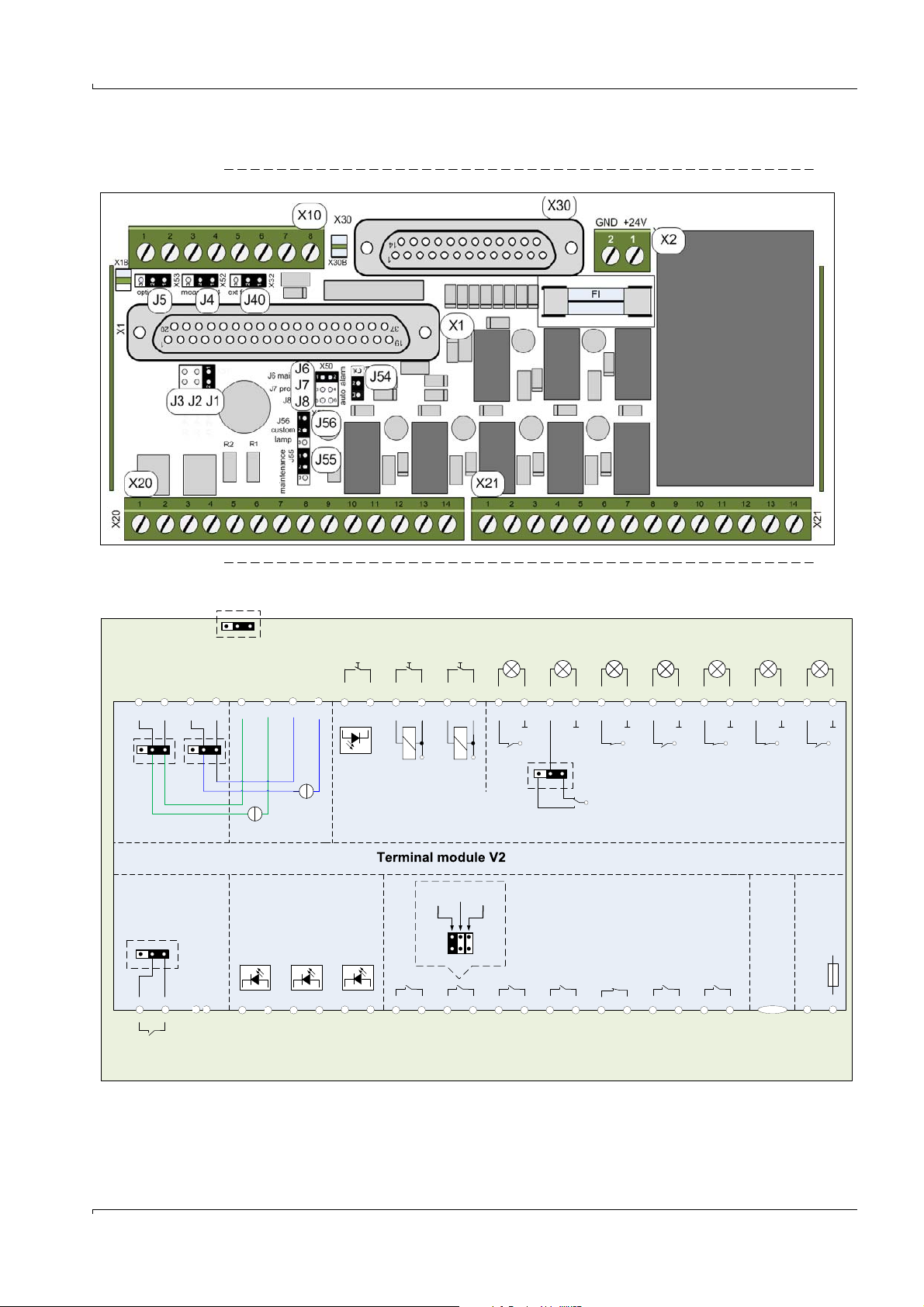
V2 terminal module
Voltage
supply
Reference
value
(optional)
Measured
value
(optional)
Lamp
test
Service
switch
Failure
Special
state
Alarm
Pre-alarm
Calibration
-
+
114
-
+
215
-
+
316
-
+
720
-
+
821
-
+
922
-
+
10 23
-
+
11 24
X30
Status outputs
(operating unit)
Operator panel connection
Customer-
specific
-
+
619
System
in service
-
+
518
X21
Customer-
specific
Set system
in service
1
X10
Lamp test
output
+
78
External
malfunc-
tion
56
X10 X20
Maintenance
block
External
calibration/
calibration block
Gas supply
malfunction
Measured
value
X20
Reference
value
Operating unit
System plug
-
+
GND +24V
X2X1
Status inputs
(operating unit)
Analog outputs
Alarm
reset
Failure
Measured
value
valid
Alarm
Pre-alarm Calibration
1 ……..…. 37
1
2
FI
1 A MT
GND
+24V
GND
+24V
GND
+24V
GND
+24V
GND
+24V
GND
+24V
GND
J56
+24V
J40
NC
Only internal use on
terminal module V2
Parallel to
lamp test
X30.1-14
Only internal use on
terminal module V2
+24V
+24V
NO
NCNONO
NO
NCNC
NO
+
56
78
13 14
910
11 12342
J6 J8J7
NO
NO
NO
NONO
NC
-
+
34
-
+
12
-
+
34
-
+
12
4 … 20mA 4 … 20mA
J5 J4
-
+
12
11
-
+
10 9
-
+
14 13
4 … 20mA 4 … 20mA
+
-
+
-
Service
requirement
Lower
pre-alarm
Lower
alarm
J5
123
123123
123
123
7.1.1 Terminal and connector pin assignments
Fig. 20 Terminal assignment
Fig. 21 Connector pin assignment
Subject to change without notice
EuroFID3010 Inline UEG · Operating Instructions · 8016307/YL25/V 2-2/2018-04 · © SICK AG 55
Page 56

7.2 Analog outputs
7.2.1 Description
7.2.1.1 Analog output “Measured value”
CAUTION: Higher current when turning on
When the operating unit is turned on, the analog outputs briefly output a
current of 22 mA.
▸
Before turning on the operating unit: Inform any affected stations and/or
deactivate connected devices.
Status of the “Measured value” output Current
Failure 0 mA
Measured value not valid 2 mA
0-100% LEL 4 … 20 mA
● The current measured value is displayed during calibration (test gas concentration).
● If the measuring range is exceeded, the analog output switches to a value greater than
21 mA.
● If the measured value is below the measuring range, the analog output switches to a
value less than 4 mA.
V2 terminal module
7.2.1.2 Analog output “Reference value”
● The “Reference value” analog output corresponds to the “Measured value” analog
output, but keeps the last valid measured value during calibration.
7.2.2 Terminal assignment X10 and X20
Location of the connector pins → p. 55, Fig. 20.
X10 terminal strip
Functional group
Function
Analog outputs Measured value -3 +4
Reference value -1 +2
X20 terminal strip
Functional group
Function
Analog outputs Measured value -3 +4
Reference value -1 +2
7.2.3 Configuration (jumpers)
Standard configuration: Analog outputs at X20 terminal strip only.
Optionally, parallel output at X10 is possible.
Location of the jumpers → p. 55, Fig. 20.
Table 1 Jumpers for the analog outputs X10 - X20
Analog output at X20 at X20 and X10
Analog output 1 “Measured value” J4, bridged: 1-2 J4, bridged: 2-3
Analog output 2 “Reference value” J5, bridged: 1-2 J5, bridged: 2-3
The analog outputs are potential-free with respect to the electronics.
They have a common negative terminal (not potential-free relative to one
another).
56 EuroFID3010 Inline UEG · Operating Instructions · 8016307/YL25/V 2-2/2018-04 · © SICK AG
Subject to change without notice
Page 57

V2 terminal module
7.3 Digital outputs (threshold value alarm, status)
7.3.1 Description
● Number of digital outputs: 7
● Type: relay outputs
– Max. voltage: 24 V
– Max. current: 500 mA
NOTICE:
Inductive loads (e.g. relays, solenoid valves) may destroy the relay switching
contacts.
▸
Separate anti-surge diodes must be installed.
7.3.2 Terminal assignment
7.3.2.1 X21 terminal assignment
Location of the terminal pin → p. 55, Fig. 20.
Connector pin Terminal Name Switching state
X21 1 – 2 DO 1 NO System set to maintenance
3 – 4 DO 2 NO Customer-specific
5 – 6 DO 3 NO Failure
7 – 8 DO 4 NO Measured value valid
9 – 10 DO 5 NO Pre-alarm
11 – 12 DO 6 NO Calibration
13 – 14 DO 7 NO Alarm
[1] NO: “Normally Open”.
[2] The “System in Service” output is activated via the key switches X30.3 and X30.16.
[1]
Function
[2]
Functions
Table 2 Digital outputs
Function Deactivated switching state Activated switching state
System set to maintenance
[1]
OPEN CLOSED
Customer-specific OPEN CLOSED
[2]
Failure
CLOSED OPEN
Measured value valid OPEN CLOSED
Pre-alarm CLOSED OPEN
Calibration OPEN CLOSED
Alarm CLOSED OPEN
[1] Activated if the EuroFID3010 Inline UEG can still perform measurement, but several internal conditions are no
longer in the operating range for valid measuring values. A corresponding message is shown on the display.
[2] This switching logic means “Failure” is signaled when the AC power fails (e.g. also in case of a cable break, switched
off/failed device).
Subject to change without notice
EuroFID3010 Inline UEG · Operating Instructions · 8016307/YL25/V 2-2/2018-04 · © SICK AG 57
Page 58
Configuration (jumpers)
Location of the jumpers → p. 55, Fig. 20.
Configuration of DO 2 (→ p. 57, § 7.3.2.1):
Table 3 Jumpers
Function of the digital output J6 J7 J8
Service requirement (preset) Bridged Open Open
Pre-alarm if the threshold value is not reached
(L1) or first pre-alarm (H0)
Alarm if the threshold value is not reached (L2)
[1] This function must be configured in the menu (Menu: Threshold value indicator → p. 98, § 11.9).
Alarm
● “Alarm” remains activated until it is reset via the digital input “Alarm reset” (X30.2 +
X30.15).
● “Alarm” is active during commissioning.
After switching to measuring mode, “Alarm” is automatically reset.
Note:
The first time the EuroFID3010 Inline UEG switches to the measuring mode, the alarm
is automatically reset.
To prevent this function, connect jumper J54.
● “Alarm” is routed via two safety relay contacts switched in series, which are both
positively driven with an N/C contact.
[1]
[1]
Open Bridged Open
Open Open Bridged
Only 1 alarm function can be activated,
i.e. only 1 jumper may be placed.
NOTICE:
▸
Use exclusively the digital output “Alarm” as a safety contact.
V2 terminal module
58 EuroFID3010 Inline UEG · Operating Instructions · 8016307/YL25/V 2-2/2018-04 · © SICK AG
Subject to change without notice
Page 59
V2 terminal module
7.3.2.2 X30 terminal assignment
External lights (e.g. for a switching cabinet) can be connected at X30.
Location of the terminal pin → p. 55, Fig. 20.
Connector pin Terminals Function
X30 +5 -18 System in Service
Configuration (jumpers)
The digital output X30.6 + X30.19 can be inverted:
Table 4 Bridge configuration
Bridge J56 Signal not activated Signal activated
Bridged: 1–2 Switching contact open Switching contact closed
Bridged: 2–3 Switching contact closed Switching contact open
Table 5 Bridge configuration
Bridge J54 Signal not activated
Bridged: 1–2 Automatic alarm
Bridged: 2–3 Manual alarm
In case of “Manual alarm,” the alarm remains active even after switching to active
measuring mode.
The alarm must then be acknowledged with the alarm reset button (the alarm reset button
must be installed separately by the user).
+6 -19 Customer-specific
+7 -20 Failure
+8 -21 Measured value valid
+9 -22 Alarm
+10 -23 Pre-alarm
+11 -24 Calibration
Subject to change without notice
EuroFID3010 Inline UEG · Operating Instructions · 8016307/YL25/V 2-2/2018-04 · © SICK AG 59
Page 60

7.4 Digital inputs
SIx
18 - 48 VDC
7.4.1 Description
● Number of digital inputs: 7
● The digital inputs are optical coupler inputs (→ p. 60, Fig. 22).
– Control voltage: 18-48 VDC
The control voltage must be provided externally.
7.4.2 Terminal assignment
Fig. 22 Circuit diagram
V2 terminal module
7.4.2.1
X20 terminal assignment
Location of the terminal pin → p. 55, Fig. 20.
Connector pin Terminals Name Function
X20 +9 -10 DI 1 Maintenance block
+11 -12 DI 2 External calibration/calibration block
+13 -14 DI 3 Malfunction, gas supply
“Malfunction, gas supply”
The digital input “Malfunction, gas supply” can be used to monitor the gas supply.
● If the digital input is “active,” the EuroFID3010 Inline UEG displays the status “Service
requirement.”
“External calibration/calibration block”
● Calibration control via the “Calibration control” menu (→ p. 118, §12.8).
● To block calibration: Input to 24 V (→ p. 121, §12.8.1.6).
If the calibration block is active, no calibration can be carried out.
● If “External calibration” is to be used: Select “ex.auto” in the “Calibration control” menu
(→ p. 119, § 12.8.1).
● To start an automatic calibration: Set the “External calibration/calibration block” input
to “0 V” for 1-2 seconds.
“Maintenance block”
When the “Maintenance block” digital input is activated, it is not possible to use operating
functions to interrupt the measuring mode.
Subject to change without notice
60 EuroFID3010 Inline UEG · Operating Instructions · 8016307/YL25/V 2-2/2018-04 · © SICK AG
Page 61

V2 terminal module
7.4.2.2 X10 terminal assignment
Location of the terminal pin → p. 55, Fig. 20.
Connector pin Terminals Name Function Jumpers
X10 5 - 6 DI 1 Signals an external malfunction at
“External malfunction”
The external switch can be used to signal an external malfunction (e.g. temperature
monitoring).
This signal is output exclusively at terminal X21.5 and X21.6. No further processing/
signaling takes place.
7.4.2.3 X30 terminal assignment
Location of the terminal pin → p. 55, Fig. 20.
Connector pin Terminals Name Function
X30 -1 +14 DI 1 Lamp test
[1] Switches a photoMOS relay; the switching contact (pushbutton switch) is not subjected to lamp load.
J40 not bridged
X21.5 and X21.6
Does not signal an external
J40 bridged
malfunction
7 - 8 DI 2 Not used
[1]
-2 +15 DI 2 Alarm reset
-3 +16 DI 3 Service/maintenance switch “System in Service”
“Lamp test”
A pushbutton switch can be connected to the “Lamp test” digital input to test connected
indicator lights.
● The lamp test signal is output in parallel to the terminals X10-7 and X10-8.
● The “Lamp test” digital input switches a photoMOS relay.
● The current relay states are not changed.
“Alarm reset”
A pushbutton switch can be connected to the “Alarm reset” digital input to reset an active
alarm.
The alarm is reset by closing the contact.
“Service/maintenance switch”
A switch can be connected to the “Service/maintenance switch” digital input to place the
V2 terminal module into maintenance mode.
This signal is only used in the V2 terminal module and has no further effect on how the
EuroFID3010 Inline UEG functions.
▸
The signal must be forwarded to a higher-ranking level (e.g. control center).
● The “System in Service” digital output at the X30 pin connector is activated.
● The “Measured value valid” signal is activated.
● All digital outputs for maintenance and malfunction messages are deactivated
(however, the “Measured value” analog output continues to output 0 mA during
malfunctions).
● The “Pre-alarm” digital output is activated.
● The “Alarm” digital output is activated as soon as the operating unit activates the alarm,
Subject to change without notice
but is not latching (refer to → p. 98, §11.9).
EuroFID3010 Inline UEG · Operating Instructions · 8016307/YL25/V 2-2/2018-04 · © SICK AG 61
Page 62
7.5 Installation
7.5.1 Mounting rails
To mount the V2 terminal module, the following types of standard mounting rails are
available:
● Top hat rail EN50022-35 x 7.5 (and 35 x 15, plus derivative profiles with a T-slot)
● G-rail EN50035-G32
▸
Attach the V2 terminal module to a mounting rail.
7.5.2 Signal cable
When connecting the signal lines, please observe the following:
● Use shielded cable for all signal connections.
● Take into consideration the shielding concept of the higher-level system.
NOTICE: Malfunctions due to unsuitable cables
▸
Use only suitable cable.
▸
Install the cable carefully,
otherwise the specified electromagnetic compatibility (EMC) may not be
achieved and malfunctions may result.
V2 terminal module
NOTICE: Sensitive electronics
▸
Before making signal connections (including with plug-in connectors):
Switch off power to all devices to be connected,
otherwise electronic components may be damaged.
62 EuroFID3010 Inline UEG · Operating Instructions · 8016307/YL25/V 2-2/2018-04 · © SICK AG
Subject to change without notice
Page 63
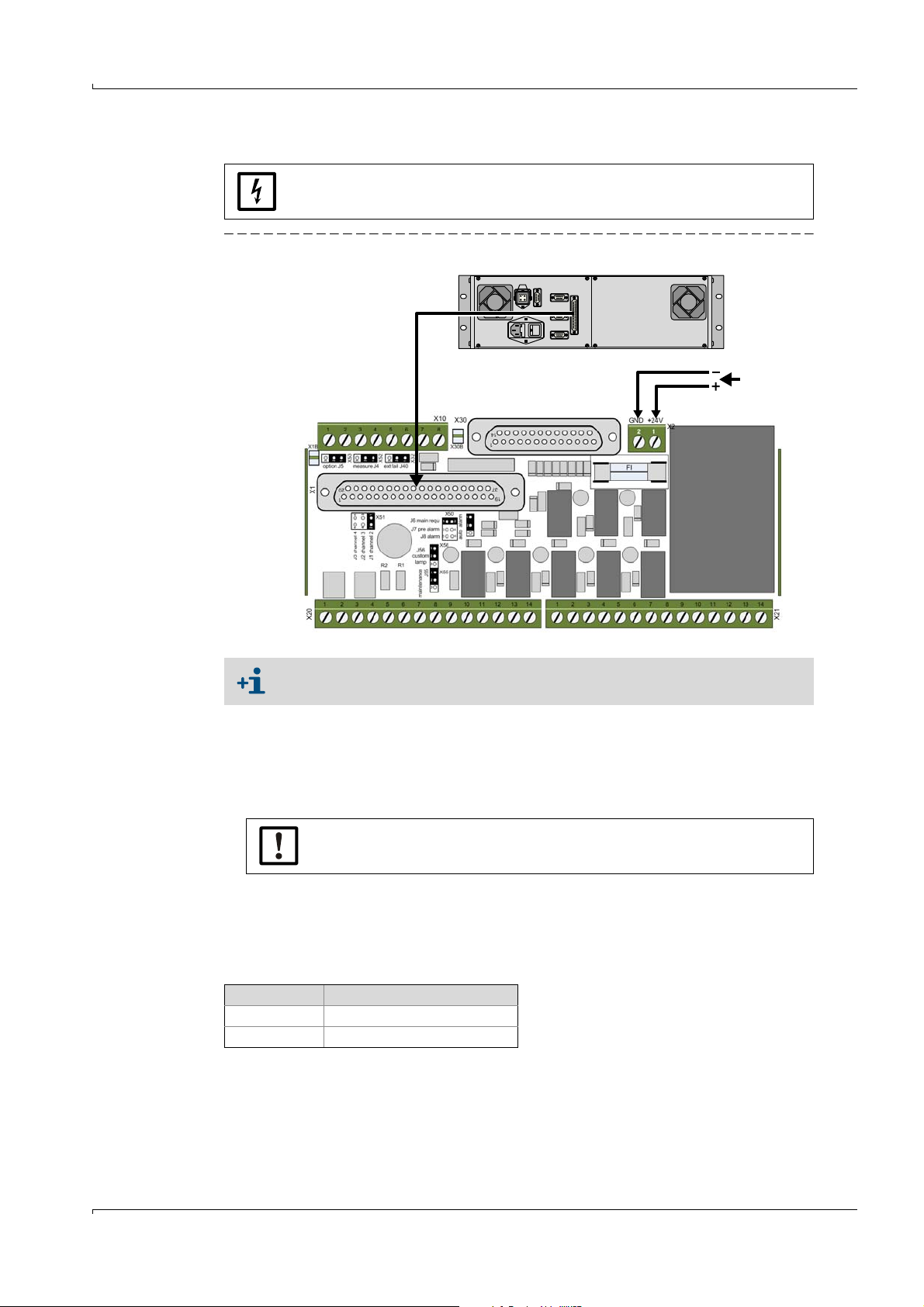
V2 terminal module
24 VDC
Connection cable
Operating unit
V2 terminal module
7.6 Electrical connection
When working on the V2 terminal module: Switch off power to the terminal
module.
Fig. 23 V2 terminal module
Subject to change without notice
● Fuse: 1 A (slow fuse), 250 V, D5x20
7.6.1
7.6.2 Connect supply voltage
Attach connection cable
Use only the SICK connection cable (Part no. → p. 171, § 16.11.5):
▸
Connect the “Connecting module” plug connector to the V2 terminal module.
▸
Connect the “Remote unit” plug connector to the operating unit.
The pin assignments of the connection cable are not symmetric.
▸
Therefore do not confuse the ends of the connection cable.
The V2 terminal module requires an external voltage supply (24 VDC/17 W).
The external voltage supply must comply with SELV (safety extra low voltage).
▸
Connect the voltage supply to the X2 connector pin (→ p. 63, Fig. 23).
Terminal
1 24 VDC (17 W)
2GND
EuroFID3010 Inline UEG · Operating Instructions · 8016307/YL25/V 2-2/2018-04 · © SICK AG 63
Page 64

V2 terminal module
64 EuroFID3010 Inline UEG · Operating Instructions · 8016307/YL25/V 2-2/2018-04 · © SICK AG
Subject to change without notice
Page 65

Commissioning
EuroFID3010 Inline UEG
8 Commissioning
Preparation
Activation procedure
Function test
Subject to change without notice
EuroFID3010 Inline UEG · Operating Instructions · 8016307/YL25/V 2-2/2018-04 · © SICK AG 65
Page 66
8.1 Initial commissioning
WARNING:
Never start up the device without first having it checked by authorized
personnel!
▸
Before you use the EuroFID3010 Inline UEG in safety-relevant applications
in your company, it must first be inspected and approved for use by
authorized personnel.
▸
The results of this inspection must be documented.
Preparation
▸
Ensure correct supply of operation gases (specifications → p. 166, § 16.8).
▸
Check gas connections.
▸
Check gas lines for leaks: leak detection spray, sensor for combustible gases.
Procedure
▸
Check configuration
– Name of analyzer
– Sensor block temperature
–Alarm threshold
–Conversion factors
– Test gas concentration
– Classification temperature
▸
Calibration
– Calibrate zero gas and span gas
– Check calibration
▸
Hardware check
– Check alarm contact
– Check “Failure” and “Measured value valid” contacts
Commissioning
66 EuroFID3010 Inline UEG · Operating Instructions · 8016307/YL25/V 2-2/2018-04 · © SICK AG
Subject to change without notice
Page 67
Commissioning
8.2 Activation procedure
▸
Turn on external AC power switch or power switch on the back of the operating unit.
▸
Switch on external voltage supply to the V2 terminal module.
CAUTION: Higher current when turning on
When the operating unit is turned on, the analog outputs briefly output a
current of 22 mA.
▸
Before turning on the operating unit: Inform any affected stations and/or
deactivate connected devices.
Note
If the operating unit has been turned off intermittently: Switch off the supply voltage to the
V2 terminal module, otherwise the automatic alarm reset will not be activated and the
active alarm will have to be acknowledged with the alarm reset button.
1 The “Alarm” signal is active during commissioning.
2 RAM-Test running. This message is displayed for approx. 2 minutes:
Start
RAM-Test running
Internal memory test.
Duration of display: Several minutes.
No entries can be made here.
3 Then, the following will be displayed:
E U R O F I D
Software Rev.5.2
Configuration5.2
V5.2 02.07.03
Type 100%LEL scale
5562
Prod.date 08.2013
0.0 % LEL
Range ... 100
4 No LED is lit up.
5 Instrument air is introduced.
6 Zero gas is introduced.
← Device name
← Software version
← Software version / Release date (Day.Month.Year)
← Software type
Date of manufacture of the operating unit (Month.Year)
Subject to change without notice
EuroFID3010 Inline UEG · Operating Instructions · 8016307/YL25/V 2-2/2018-04 · © SICK AG 67
Page 68

Commissioning
7 The following is displayed during the heating up phase:
Warm Up
1380 s
Temp. sensor block
193.3 195.0 CEL
Pump ON
Act 2450 mbar
Flame OUT
[1] If the set temperature is not reached within the remaining running time, the error message “36 Analyz.heat.” is
displayed (→ p. 149, §15.6).
← Maximum remaining running time
← Current actual temperature / set temperature
[1]
The heating up phase can take up to 1.5 hours.
8 Fuel gas is introduced.
9 The flame is ignited.
The following is displayed during the ignition process:
Ignition
30.05.2013
Ignition
Flame OUT
Current ON
← Status of the FID flame
10 When the EuroFID3010 Inline UEG and all peripheral devices with connected status
signals are ready for operation, the EuroFID3010 Inline UEG switches to measurement
mode:
– The measurement display appears on the operating unit screen (→ p. 77, § 10.3).
10.05.2013 13:08:10
382
0.0
Propane % LEL
FID1
--------------------
Range ... 100.0
← Current date/current time
← Operating hours
← Current measured value
← Physical unit
← Name of analyzer
← Bar display of the measured value
← Current measuring range (measuring range end value)
– The “Alarm” signal is reset. → p. 118, §12.8 EuroFID3010 Inline UEG.
If the EuroFID3010 Inline UEG has not been in operation for quite some
time, it may occur that it is not completely warmed up despite the heating
up phase.
▸
Wait another two hours and perform a “Manual calibration” (→ p. 122,
§12.10).
68 EuroFID3010 Inline UEG · Operating Instructions · 8016307/YL25/V 2-2/2018-04 · © SICK AG
Subject to change without notice
Page 69

Commissioning
11 If the function “Manual calibration” is activated (→ p. 118, §12.8): Start manual
calibration (→ p. 122, § 12.10).
8.2.1 How to ascertain that the device is in proper operating condition
Analyzer unit
● Supply of operating gases verified (Specifications → p. 166, §16.8).
– Instrument air
–Fuel gas
–Calibration gas
● Fan (optional) is running (noise, moving air).
Operating unit
● “OK” LED lights up.
● No malfunction messages (display).
● V2 terminal module:
–“Alarm” digital output inactive.
– “Measure” digital output active.
8.2.2 Recognizing a special state
● The “OK” LED does not light up.
● V2 terminal module: “Special state” digital output.
Subject to change without notice
EuroFID3010 Inline UEG · Operating Instructions · 8016307/YL25/V 2-2/2018-04 · © SICK AG 69
Page 70

Commissioning
70 EuroFID3010 Inline UEG · Operating Instructions · 8016307/YL25/V 2-2/2018-04 · © SICK AG
Subject to change without notice
Page 71

Operation (General)
EuroFID3010 Inline UEG
9 Operation (General)
Access
Operation
Status messages
Subject to change without notice
EuroFID3010 Inline UEG · Operating Instructions · 8016307/YL25/V 2-2/2018-04 · © SICK AG 71
Page 72

9.1 Controls and indicators/displays
Alarm Fault Ser vice OK
8
5
2
7
Back Help Meas
4
1
0
9
6
3
Fig. 24 Controls and indicators/displays
Operation (General)
9.1.1
LEDs (indicators)
LED Significance
● The measured value has exceeded an alarm threshold value.
▸
Alarm
Fault
Service
OK
[1] Is not displayed as long as the “System in Service” status is activated.
Reset alarm (→ p. 100, § 11.11).
● The EuroFID3010 Inline UEG has failed.
● The EuroFID3010 Inline UEG does not show the current measured value.
▸
For reasons, refer to the “Diagnosis” menu (→ p. 79, §10.6).
● Maintenance is required.
Or:
● The “System in Service” status is activated (→ p. 100, §11.10).
The EuroFID3010 Inline UEG continues to show the current measured value.
▸
For reasons, refer to the “Diagnosis” menu (→ p. 79, §10.6).
● The EuroFID3010 Inline UEG shows the current measured value.
The measured value is valid.
● If “OK” is not lit up: Special state (→ p. 123, § 12.11) (e.g. ignition,
calibration).
[1]
72 EuroFID3010 Inline UEG · Operating Instructions · 8016307/YL25/V 2-2/2018-04 · © SICK AG
Subject to change without notice
Page 73

Operation (General)
Back
Help
Meas
Back
Back
9.1.2 Keypad
Button Function
9.1.2.1 Navigation principle
Opening the main menu:
▸
If the measurement display is active : Press once.
▸
If a menu function is active: Press (several times if needed) until the main menu
appears.
– If the measurement display is activated: Leads to main menu
– In the menu system: Leads to the previous menu level
– For entry functions: Deletes the last entry
– After changes: It is asked whether changes should be saved
Invokes information about the current function
Jumps directly to the measuring screen
Do not save changes
Aborts running programs (e.g. calibration)
Concludes entry
Confirms any changes
Toggles between entries
To change settings:
1 Press or until the relevant field has been highlighted.
2 With input fields: Enter the desired value.
With selection boxes: Press until the desired setting is displayed.
To finish:
1 Press or until
2 Press .
End is highlighted.
Subject to change without notice
EuroFID3010 Inline UEG · Operating Instructions · 8016307/YL25/V 2-2/2018-04 · © SICK AG 73
Page 74

Operation (General)
74 EuroFID3010 Inline UEG · Operating Instructions · 8016307/YL25/V 2-2/2018-04 · © SICK AG
Subject to change without notice
Page 75

Menus
EuroFID3010 Inline UEG
10 Menus
Measuring screen
Manual calibration
Manual ignition of the FID flame
Diagnosis displays
Language selection
Help
Subject to change without notice
EuroFID3010 Inline UEG · Operating Instructions · 8016307/YL25/V 2-2/2018-04 · © SICK AG 75
Page 76

10.1 Menu structure
Menu structure Refer to
Measure → p. 77, § 10.3
Calibration → p. 78, § 10.4
Flame ignition → p. 78, § 10.5
Diagnosis → p. 79, § 10.6
Maintenance → p. 87, § 11
Calibr. Gas Value → p. 112, §12.5.1
Conversion factors → p. 113, §12.5.2
Standby → p. 89, § 11.2
Error archives → p. 90, § 11.3
Disp. of err. arch. → p. 91, §11.3.2
Delete error arch. → p. 91, § 11.3.3
Filter change → p. 93, § 11.4
System Parameters → p. 94, §11.5
User level → p. 95, § 11.6
Calibration control
Calibration control
Calibration time
Setup temp. sensbl.
I/O parameters
I/O parameters
Alarm value setup
Purging parameters
Next menu
Time and date set
Summer/winter time
Next menu
Name of analyzer
Expert level
Zero check → p. 122, §12.10
Calib. Gas check → p. 122, §12.10
Hardware check → p. 103, §11.15
Inputs and Outputs
Analog Outputs
Digital Inputs
Digital Outputs
Analog inputs ana.
Digital inputs ana.
Digital Outputs
Interface Check
Interface Check
Front panel
LED's
LCD test
Keyboard test
Restart → p. 107, §11.16
Set Service Yes/No → p. 100, §11.10
Threshold reset → p. 100, §11.11
Language →
Language A - M
Language N-Z
General Help → p. 85, § 10.9
Menus
→ p. 96, § 11.7
→ p. 97, § 11.8
→ p. 98, § 11.9
→ p. 117, §12.7
→ p. 104, §11.15.1
→ p. 106, §11.15.3
→ p. 106, §11.15.4
p. 85, §10.8
Subject to change without notice
76 EuroFID3010 Inline UEG · Operating Instructions · 8016307/YL25/V 2-2/2018-04 · © SICK AG
Page 77

Menus
1 Measure
Meas
Back
10.2 Main menu
Main Menu
V5.2 15:08.53 D
2 Calibration
3 Flame ignition
4 Diagnosis
5 Maintenance
6 Language
7 General Help
0.0 % LEL
Range ... 100
Procedure
▸
Open the measurement display
–Main menu → Measure
or
– Press (from any menu).
If the “System in Service” status is activated (→ p. 100, §11.10), this status is
maintained.
▸
To return to the main menu: Press .
10.3 Measurement display
Function
The “Measure” menu item activates the measurement display:
10.05.2013 13:08:10
382
← Menu title
← Software version/date/menu language
→ p. 77, § 10.3
→ p. 78, § 10.4
→ p. 78, § 10.5
→ p. 79, § 10.6
→ p. 88, § 11.1
→ p. 85, § 10.8
← Current measured value
← Current measuring range (measuring range end value)
← Current date/current time
← Hours of operation of the operating unit
[1]
0.0
Propane % LEL
FID1
--------------------
Range ... 100.0
[1] Counter starts at manufacturer's works.
[2] Supplemental text for the physical unit→ p. 102, § 11.13.
[3] Measuring range 0 ... 100% LEL is permanently set.
← Current measured value
← Physical unit
← Name of analyzer
← Bar display of the measured value
← Current measuring range (measuring range end value)
[2]
[3]
The measured value is displayed digitally with plus or minus sign and units.
Display if the measured value is above or below the limits of the measuring range:
● The current measured values are shown.
● The bar diagram also flashes if the measured value is exceeded.
● If the physical measuring range of the A/D converter is exceeded:
– The message “OVF” appears on the display.
● If the measured value is below the measuring range, the measured value is displayed
with a minus sign in front of it.
Subject to change without notice
EuroFID3010 Inline UEG · Operating Instructions · 8016307/YL25/V 2-2/2018-04 · © SICK AG 77
Page 78
10.4 Calibration (note)
End
Manual calibration can be carried out via the “Calibration” menu (Main menu →
Calibration).
For a detailed description, refer to → p. 119, §12.8.1.1
10.5 Flame ignition
Function
This menu function is used to manually ignite the FID flame.
If 10 consecutive ignition attempts are unsuccessful, a malfunction message is displayed.
Procedure
1 Open the menu: Main menu → Flame ignition
Flame Ignition
Menus
← Menu title
Flame Ignition
Yes
Change or
0.0 % LEL
Range ... 100
← Selection box
← Current measured value
← Current measuring range (measuring range end value)
The main menu appears – with the addition of the word
Ignition.
78 EuroFID3010 Inline UEG · Operating Instructions · 8016307/YL25/V 2-2/2018-04 · © SICK AG
Subject to change without notice
Page 79
Menus
< Continue >
< Continue >
10.6 Diagnosis
10.6.1 Accessing the diagnosis messages
1 Open the menu: Main menu → Diagnosis
Diagnosis
← Menu title
System failure msg.
0
Service requ. repor.
0
0.0 % LEL
Range ... 100
← No. of current system failure messages
← No. of current service requirement messages
← Current measured value
← Current measuring range (measuring range end value)
2 Press to view the next message in the queue.
>>>
Any malfunction messages are displayed first (→ p. 79, §10.6.2).
>>>
These are followed by the displays of the operating parameters (→ p. 80, § 10.6.3).
10.6.2 Malfunction messages in the diagnosis function
Classification of malfunction messages
● “System failure”: Malfunctions that lead to a special state.
● “Maintenance requirement”: Malfunctions that do not (yet) negatively affect the
measured values.
Example of a malfunction message
Diagnosis
System failure
Flame not burning
Please check fuel
Gas- and fuelAir ways and the
Flame control
← Menu title
← Malfunction classification
← Message text
Range ... 100
← Current measuring range
The malfunction messages cannot be manually deactivated.
A malfunction message disappears when the malfunction has been remedied.
Subject to change without notice
EuroFID3010 Inline UEG · Operating Instructions · 8016307/YL25/V 2-2/2018-04 · © SICK AG 79
Page 80

10.6.3 Operational displays in the diagnosis function
< Continue >
< Continue >
The following displays appear in succession:
Alarm status (threshold value messages)
Diagnosis
← Menu title
Alarm
Threshold H2 NO
Threshold H1 YES
Threshold L1 NO
Threshold L2 NO
← Alarm status
←
←
←
[1] [2]
Menus
0.0 % LEL
Range ... 100
[1] YES = activated / NO = not activated.
[2] If YES is displayed although the current measured value is inside the threshold value: The latching function is
activated and needs to be deactivated manually (→ p. 100, §11.11).
← Current measured value
← Current measuring range (measuring range end value)
Temperature of the electronics in the analyzer unit
Diagnosis
← Menu title
Inside Temp.EleAnaly
Actual 32.8 CEL
0.0 % LEL
Range ... 100
← Current temperature (CEL = °C)
← Current measured value
← Current measuring range (measuring range end value)
If the temperature of the analyzer unit rises above:
● 85°C: “Service requirement” is activated.
● 90°C: “Failure” is activated.
In both cases, a malfunction message is displayed and the heating of the
sensor block is completely turned off.
If the failure occurs due to an error during calibration, you can attempt to reset the cause of
the failure by opening the Calibration menu again (calibration is not started).
The second time the calibration menu is opened, the calibration will start again if the error
has been reset.
In case of failure, you can attempt to reset the error through manual ignition.
80 EuroFID3010 Inline UEG · Operating Instructions · 8016307/YL25/V 2-2/2018-04 · © SICK AG
Subject to change without notice
Page 81
Menus
< Continue >
< Continue >
Pressure ratios at the ejector pump
NOTICE:
The dilution factor must be between 2900 and 4900.
Diagnosis
Sample Input Pressur
actual 996.5mbar
Instr.-Air Pressure
actual 2404.6mbar
Sample Gas Pressure
actual 1145.3mbar
Factor Pinp./Pmeagas
0.8766
Factor Pdriv/Pmeagas
2.1013
0.0 % LEL
Range ... 100
← Menu title
← P2 (P): Sample gas pressure at the gas inlet of the analyzer
[1]
unit
← P1 (T): Pressure of instrument air at the ejector pump
←
← Q1: Ratio of P2 to P3
← Q2: Ratio of P1 to P3
← Current measured value
← Current measuring range (measuring range end value)
P3 (M): Sample gas pressure before the sample gas capillary
[2]
[1] Target range: Ambient pressure: ± 50 mbar; greater deviations trigger a malfunction message (system failure).
[2] Determines the suction of the ejector pump.
[3] Backpressure upstream from the sample gas capillary; is kept constant relative to the ambient pressure.
Control of the ejector pump
Diagnosis
Ejector
Fixed P
Sample Input Pressur
actual 1006.6 mbar
Instr.-Air Pressure
actual 2404.6 mbar
Sample Gas Pressure
actual 1145.3 mbar
Factor
3741.6650
0.0 % LEL
Range ... 100
← Menu title
← Setpoint value: ambient pressure – (5-10 mbar)
← Setpoint value: 2350-2500 mbar
← Setpoint value: ambient pressure + 130 mbar
← Display: 2900-4900 (valid range)
← Current measured value
← Current measuring range (measuring range end value)
[3]
Subject to change without notice
EuroFID3010 Inline UEG · Operating Instructions · 8016307/YL25/V 2-2/2018-04 · © SICK AG 81
Page 82

Temperature control of the sensor block
< Continue >
< Continue >
Diagnosis
← Menu title
Menus
Sensor block settemp
195 CEL
Setup temp. sensbl.
194.76 CEL
SensHeating On/Off
ON 42.1%
0.0 % LEL
Range ... 100
← Setpoint temperature of the sensor block (CEL = °C)
← Current temperature of the sensor block (CEL = °C)
← Current heater output
← Current measured value
← Current measuring range (measuring range end value)
[1]
[1] Notes → p. 96, § 11.7.
Status of flame control and solenoid valves
Diagnosis
Flame Control Temp.
267 CEL
Ignit. Coil OUT
SV Ignit. Gas OUT
SV Ejector ON
SV Ignit. Gas ON
SV Span Gas OUT
SV Zero Gas OUT
Flow barrier OUT
0.0 % LEL
Range ... 100
[1] ON as long as the ignition coil is heated during the ignition process
[2] SV = solenoid valve; ON = valve open / OFF = valve closed.
[3] ON during ignition of the FID flame.
[4] ON when the sensor block has reached the set temperature and there are no malfunctions.
[5] ON when the FID flame burns and instrument air is supplied and there are no malfunctions.
[6] ON as long as the solenoid valve of the flow barrier (optional) is activated (i.e. during maintenance of the sample
gas filter).
← Menu title
← Temperature near the flame (CEL = °C)
← Status of the ignition coil of the FID flame
← Solenoid valve status
← Solenoid valve status
← Solenoid valve status
← Solenoid valve status
← Solenoid valve status
← Flow barrier status (optional)
← Current measured value
← Current measuring range (measuring range end value)
[2] [3]
[2] [4]
[2] [5]
[2]
[2]
[6]
[1]
82 EuroFID3010 Inline UEG · Operating Instructions · 8016307/YL25/V 2-2/2018-04 · © SICK AG
Subject to change without notice
Page 83

Menus
< Continue >
< Continue >
Calibration drift (deviation)
The results of the last calibration are displayed:
Diagnosis
Calibration Date
10.05.2013 14:48:29
Zero drift
0.2%
Calib. gas dr. total
5.2%
Drift since last Cal
3.8%
0.0 % LEL
Range ... 100
[1] Relative to measuring range end value.
← Menu title
← Date/time of last calibration
← Zero drift since last basic calibration
← Sensitivity shift since last basic calibration
← Sensitivity shift since last calibration
← Current measured value
← Current measuring range (measuring range end value)
The “deviations” are automatically compared to the alarm settings.
Software system type
Diagnosis
System_type
Type_100%_LEL_scale
4321
Prod.date 08.2013
V6.0.0.4 02.07.13
Analyzer
V2.05
← Menu title
← Configuration type of the installed software
← Serial number of the operating unit
← Manufacturing date of the operating unit
← Version/release date of the installed software
← Version of the analyzer firmware
[1]
[1]
0.0 % LEL
Range ... 100
Subject to change without notice
← Current measured value
← Current measuring range (measuring range end value)
EuroFID3010 Inline UEG · Operating Instructions · 8016307/YL25/V 2-2/2018-04 · © SICK AG 83
Page 84

Data of the installed ejector pump
< Continue >
<END>
There are four data records for the ejector pump (
Diagnosis
Param. SampleGasPump
Fixed P
Ser.No.:90204042
1/4
A33 = +5.72905122
A32 = -10.2348748
A31 = +5.18833320
A30 = -0.50595734
DiluFac: 3645.10
0.0 % LEL
Range ... 100
[1] Internal unit (not a physical value)
← Menu title
← Type of propellant pressure setting
← Serial number of the ejector pump (factory setting)
← Data record no. 1 of 4
← Coefficients of the ejector characteristic curve
←
←
←
← Current dilution factor
← Current measured value
← Current measuring range (measuring range end value)
1/4 to 4/4, with data for A3x to A0x):
[1]
Menus
Last display of
Diagnosis:
Diagnosis
Param. SampleGasPump
Fixed P
Ser.No.:90204042
4/4
A03 = +8.70768063
A02 = -65.9470894
A01 = +92.9065891
A00 = -36.9345441
DiluFac: 3645.10
0.0 % LEL
Range ... 100
10.7 Maintenance (note)
Refer to → p. 87, § 11
← Menu title
← Type of propellant pressure setting
← Serial number of the ejector pump (factory setting)
← Data record no. 4 of 4
← Coefficients of the ejector characteristic curve
←
←
←
← Dilution factor for this ejector pump
← Current measured value
← Current measuring range (measuring range end value)
84 EuroFID3010 Inline UEG · Operating Instructions · 8016307/YL25/V 2-2/2018-04 · © SICK AG
Subject to change without notice
Page 85

Menus
Back
< Continue >
Back
10.8 Language (language selection)
● German
● English
● French
● Spanish
● Russian
Procedure
1 Open the menu: Main menu → Language.
Language
1 Language A - M
2 Language N - Z
← Menu title
2 Open
Language
Language A - M
1
2 German
3
4
5 French
6 English
7
8
9
0.0 % LEL
Range ... 100
Language A - M.
3 Select the desired language.
4 Press to exit the menu.
10.9 General help
Function
The “General Help” contains brief information on the keypad and menu functions.
Procedure
▸
Open the menu: Main menu → General Help.
General Help
German
The following sections offer general
information for the
EUROFID.
A menu item will be
selected with the
arrow keys or the
hotkeys.
0.0 % LEL
Range ... 100
← Menu title
← Menu title
Subject to change without notice
EuroFID3010 Inline UEG · Operating Instructions · 8016307/YL25/V 2-2/2018-04 · © SICK AG 85
▸
To view additional information: Press .
▸
To close the help function: Press .
Page 86

Menus
86 EuroFID3010 Inline UEG · Operating Instructions · 8016307/YL25/V 2-2/2018-04 · © SICK AG
Subject to change without notice
Page 87

Maintenance menu
EuroFID3010 Inline UEG
11 Maintenance menu
Settings
System information
Test functions
Subject to change without notice
EuroFID3010 Inline UEG · Operating Instructions · 8016307/YL25/V 2-2/2018-04 · © SICK AG 87
Page 88

11.1 Maintenance menu
*
Password protection
The Maintenance submenu is password-protected. A password must be entered to access
it.
● The password is 123789 and cannot be changed.
● As long as the “Service lock” digital input is activated, access to the
Maintenance submenu is blocked; a corresponding message appears after
entering the password.
How to open the Maintenance submenu:
1 Open the Maintenance submenu: Main menu → Maintenance.
>>>
The dialog for entering the password appears:
Maintenance
Passwordinput
Escape:
=
<BACK>
Maintenance menu
← Menu title
← Input field (unchangeable: 123789)
0.0 % LEL
Range ... 100
2 Enter the following password into the input field:
← Current measured value
← Current measuring range (measuring range end value)
123789
3 Press .
>>>
The “Maintenance” menu appears and is available for use.
Maintenance
1 Calibr. Gas Value
2 Conversion factors
3 Standby
4 Error archives
5 Filter change
6 System parameters
7 Set Service
← Menu title
→ p. 112, §12.5.1
→ p. 113, §12.5.2
8 Threshold reset
0.0 % LEL
Range ... 100
>>>
Access to the “Maintenance” submenu is allowed until the measurement display is
← Current measured value
← Current measuring range (measuring range end value)
opened once more.
88 EuroFID3010 Inline UEG · Operating Instructions · 8016307/YL25/V 2-2/2018-04 · © SICK AG
Subject to change without notice
Page 89
Maintenance menu
< E n d >
11.2 Standby
Function
Special state “Standby”:
● The fuel gas supply is cut off and the flame is extinguished.
● All components remain at operating temperature.
● The measuring system is continuously purged with zero gas.
● The “Measured value valid” digital output is deactivated.
● The “Alarm” digital output is deactivated.
● The analog outputs are maintained.
● The “OK” LED does not light up.
● The ejector pump and the heater of the sensor block remain in operation.
Procedure
1 Open the menu: Main menu → Maintenance → Standby
Standby
← Menu title
Standby
< NO >
0.0 % LEL
Range ... 100
← Selection box
← Current measured value
← Current measuring range (measuring range end value)
2 Ending standby:
a) Change selection box to “
NO”: The FID flame is automatically ignited.
b) The “Maintenance” menu is displayed (→ p. 88, §11.1).
“Standby” mode is automatically deactivated as soon as you open the
measurement display (→ p. 77, § 10.3).
Subject to change without notice
EuroFID3010 Inline UEG · Operating Instructions · 8016307/YL25/V 2-2/2018-04 · © SICK AG 89
Page 90

11.3 Error archives
11.3.1 Function of the error archives
The EuroFID3010 Inline UEG saves the following in the Error archives:
● Malfunction messages in abbreviated form
● Activation of the “System in Service” status
The error archives contain the most recent messages.
These messages can be:
● Viewed on the display
● Fully deleted
Open: Main menu → Maintenance → Error archives
Error archives
1 Disp.of err. arch.
2 Delete error arch.
Maintenance menu
← Menu title
0.0 % LEL
Range ... 100
← Current measured value
← Current measuring range (measuring range end value)
Note
The error archive is automatically deleted
– after a restart
–after a switch off
– after a failure of the power voltage
90 EuroFID3010 Inline UEG · Operating Instructions · 8016307/YL25/V 2-2/2018-04 · © SICK AG
Subject to change without notice
Page 91
Maintenance menu
<END>
Back
11.3.2 Displaying the error archives
Function
The “Error archives” menu is used to display the saved error messages on the screen. Two
messages are displayed on each “page”.
● Deleting all error messages→ p. 91, § 11.3.3
● Error messages in full detail (diagnosis function) → p. 79, §10.6.2
Procedure
1 Open the menu: Main menu → Maintenance → Error archives → Disp. of err. archiv
>>>
Existing error messages are displayed in the sequence they occurred (most recent
first); two error messages are shown per display page. Example:.
Disp. of err. archiv
← Menu title
15.05.2013 09:52:31
In Service00079
Service_requir(Diag)
15.05.2013 09:52:33
In Service 0074
Service_requir(Diag)
0.0 % LEL
Range ... 100
[1] Number of the program section in which the error was localized.
>>>
If additional error messages are available, < Continue > will be displayed.
2
< Continue > or <END >: Press .
3 Browse: or
Skip to beginning or end or
▸
To cancel: Press .
11.3.3 Deleting the error archive
Function
All saved error messages in the error archives can be deleted.
NOTICE:
Deletion is permanent and cannot be reversed.
← Date/time
← Message / localization
← Automatic reaction
← Date/time
← Message / localization
← Automatic reaction
← Current measured value
← Current measuring range (measuring range end value)
[1]
[1]
Subject to change without notice
EuroFID3010 Inline UEG · Operating Instructions · 8016307/YL25/V 2-2/2018-04 · © SICK AG 91
Page 92

Maintenance menu
<END>
Procedure
1 Open the menu: Main menu → Maintenance → Error archives → Delete error archive
Delete error archive
← Menu title
Instrum.log.register
Delete <NO >
0.0 % LEL
Range ... 100
● All error messages are deleted.
● The
Error archives menu appears.
← Selection box
← Current measured value
← Current measuring range (measuring range end value)
92 EuroFID3010 Inline UEG · Operating Instructions · 8016307/YL25/V 2-2/2018-04 · © SICK AG
Subject to change without notice
Page 93
Maintenance menu
End
11.4 Filter change special state (menu)
NOTICE:
▸
Only open the sample gas filter when the “Filter change” status is activated.
(Procedure → p. 135, § 14.5.2).
Otherwise dust-laden ambient air can enter the measuring system.
For a detailed description of the operating steps and maintenance work, refer
to → p. 135, § 14.5.2
Function
The “Filter change” menu function assists you during maintenance work on the sample gas
filter in two steps:
a) Safeguarding before starting maintenance:
– The supply of instrument air to the ejector pump is stopped. The ejector pump is
deactivated as a result; the supply of sample gas to the measuring system is
stopped.
– The supply of fuel gas is stopped, the FID flame is extinguished.
– On devices with the “flow barrier” option: The external solenoid valve is activated,
causing the sample gas in the sample gas filter to be displaced by instrument air.
b) Safe restart:
– The sample gas filter is heated to operating temperature to prevent condensation.
– The FID flame is re-ignited.
– On devices with the “flow barrier” option: The external solenoid valve is deactivated.
– The sample gas supply is activated again.
Opening the menu
The menu can only be opened when the device status “System in Service” is active.
▸
Main → Maintenance → Filter change
Maintenance
Filter change
Filter change
NO
Filter is replaced
NO
Change or
0.0 % LEL
Range ... 100
System in Service
Procedure (abbreviated)
a) Before commencing maintenance work:
▸
Open the “Filter change” menu (Main menu → Maintenance → Filter change).
▸
Set the “Filter change” status to “YES” (Selection box 1).
▸
Close the “Filter change” menu (“END,” enter key).
b) After maintenance work:
▸
Open the “Filter change” menu once again.
▸
Subject to change without notice
Set the “Filter is replaced” status to “YES” (Selection box 2).
▸
Close the “Filter change” menu (“END,” enter key).
▸
Wait until measurement mode is automatically activated once again (approx.
15 min.).
← Menu title
← Selection box 1
← Selection box 2
← Current measured value
← Current measuring range (measuring range end value)
EuroFID3010 Inline UEG · Operating Instructions · 8016307/YL25/V 2-2/2018-04 · © SICK AG 93
Page 94

11.5 System parameters (overview)
Functions in the “System parameters” submenu
● User settings
● Calibration settings
● Reset and test of the integrated microcomputer
● Device configuration by the manufacturer (protected)
“System parameters” menu
It is only possible to open the “System parameters” menu if the device status “System in
Service” is activated.
1 If the device status “System in Service” is not activated: Activate the device status
“System in Service” (→ p. 100, § 11.10).
2 Main menu → Maintenance → System parameters.
System Parameters
← Menu title
Maintenance menu
1 User level
2 Expert level
3 Zero check
4 Calib. Gas check
5 Hardware check
6 Restart
Meas.value(format)unit
Measuring range ...value
System in Service (blink)
Service_requir(Diag)
→ p. 95, §11.6
← Not described in these Operating Instructions
→ p. 122, §12.10.1
→ p. 122, §12.10.2
→ p. 103, §11.15
→ p. 107, §11.16
94 EuroFID3010 Inline UEG · Operating Instructions · 8016307/YL25/V 2-2/2018-04 · © SICK AG
Subject to change without notice
Page 95

Maintenance menu
11.6 User level (activation)
Functions
The “User level” contains device settings for users. The functions are divided into two
menus, which can be opened in succession.
Opening the “User level” menu
▸
Open the “User level” submenu: Main menu → Maintenance → System parameters →
User level
System Parameters
User level
1 Calibrationcontrol
2 Setup temp.sensbl.
3 I/O - parameters
4 Alarm value set up
5 Purging parameter
6 Next menu
0.0 % LEL
Range ... 100
System in Service
▸
To open the second selection menu: Select Next menu.
System Parameters
User level
← Menu title
→ p. 117, § 12.7
← Opening the second selection menu
← Menu title
1 Time and date set
2 Summer/winter time
3 Unit of measurem.
4 Name of analyzer
0.0 % LEL
Range ... 100
System in Service
Subject to change without notice
EuroFID3010 Inline UEG · Operating Instructions · 8016307/YL25/V 2-2/2018-04 · © SICK AG 95
Page 96

11.7 Temperature of the sensor block
End
Function
The sensor block is heated to prevent condensation in the parts in contact with the sample
gas. The setpoint temperature of the heater is adjustable.
Setpoint temperature T
Setting range Factory setting
A
Sensor block temperature 60 … 230 °C 195°C.
NOTICE:
The setpoint temperature (T
classification temperature (T
) must be set to a value at least 25 K below the
A
, refer to type plate).
C
The sensor block temperature may not be set to a value above 195°C.
Maintenance menu
Example: T
= 220°C; T
C
Amax
≤ 195°C
Procedure
1 Open the menu: Main menu → Maintenance → System parameters → User level → Setup
temp. sensbl.
System Parameters
Setup temp. sensbl.
← Menu title
← Menu title
Sensor block settemp
195.00 CEL
CEL
Up : 60.00
up to : 230.00
Change or
0.0 % LEL
Range ... 100
← Input field
← Minimum value
← Maximum value
← Current measured value
← Current measuring range (measuring range end value)
96 EuroFID3010 Inline UEG · Operating Instructions · 8016307/YL25/V 2-2/2018-04 · © SICK AG
Subject to change without notice
Page 97

Maintenance menu
End
11.8 Display of measurement
Function
The following properties of the measurement display (→ p. 77, §10.3) can be modified:
● Resolution of the measurement display (number of digits)
● Display mode for the measured value: Instantaneous value or damped value
Opening the “I/O-Parameters” menu
▸
Open the “User level” submenu: Main menu → Maintenance → System parameters →
I/O-Parameters
System Parameters
I/O-Parameters
1 Display of measur.
0.0 % LEL
Range ... 100
System in Service
Settings for numeric measurement display
Display: - numeric -
1/100 Resolution = 1 % of the measuring range end value
1/1000 Resolution = 0.1 % of the measuring range end value
← Menu title
Procedure
1 Open the menu: Main menu → Maintenance → System parameters → User level → I/O-
Parameters → Display of measur.
System Parameters
Display: - numeric 1/1000
Change or
0.0 % LEL
Range ... 100
← Menu title
← Menu title
← Selection box 1
← Current measured value
← Current measuring range (measuring range end value)
Subject to change without notice
EuroFID3010 Inline UEG · Operating Instructions · 8016307/YL25/V 2-2/2018-04 · © SICK AG 97
Page 98

11.9 Configuring threshold value indicators (alarms)
Function
LEL threshold values can be set to monitor the LEL concentration.
If the LEL threshold is exceeded:
● The respective alarm switching contact is activated (→ p. 57, § 7.3)
● The “Alarm” LED lights up (→ p. 72, § 9.1.1).
● An alarm signal can only be reset when the measured value is inside the
respective threshold value once more.
● The alarms are not in operation when the “System in Service” device status
is activated (→ p. 100, § 11.10).
Threshold value modes
There are two threshold value modes:
a) Two threshold values for alarm alert when the threshold value is not reached (L1, L2)
and if the threshold value (H1, H2) is exceeded.
b) Three threshold values for alarm alert if the threshold value is exceeded (H0, H1, H2).
Table 6 Threshold value modes and threshold value abbreviations
Mode:
GRZ 2H 2L
/ Median value
Mode:
GRZ 3H
Alarm – when the
threshold value is not
L2 First pre-alarm H0
reached
Pre-alarm – when the
threshold value is not
L1 Second pre-alarm H1
reached
Pre-alarm – when the
threshold value is
H1 Alarm H2
exceeded
Alarm – when the
threshold value is
H2 Relations: H0 < H1 < H2
exceeded
Relations: L2 < L1 < H1 < H2
Maintenance menu
Factory setting:
● Lower threshold: 20% LEL
● Alarm: 40% LEL
Threshold values
The threshold values are displayed in the %LEL menu.
The second pre-alarm H1 is output on the V2 terminal module (X21.9+X21.10) as a pre-
alarm.
The first pre-alarm H0 is output on the V2 terminal module (X21.3+X21.4).
Prerequisite: the J8 jumper has been placed.
▸
To deactivate a threshold value: Set it to 0.
▸
Choose the threshold values to ensure that the alarm is triggered in a timely manner
before a dangerous situation occurs.
Limit Setting range Factory setting
Threshold value 0.0 … 99.99% 0.0
[1] 0.0: Threshold value is deactivated
98 EuroFID3010 Inline UEG · Operating Instructions · 8016307/YL25/V 2-2/2018-04 · © SICK AG
[1]
Subject to change without notice
Page 99

Maintenance menu
GR Z 3H
G R Z 2 H 2 L
Trigger delay
Setting: 0.0.
This setting may not be changed.
Latching of alarms
Setting: NO.
This setting may not be changed.
● The main alarm on the V2 terminal module is latching (“selfheld”).
Procedure
▸
Open the menu: Main menu → Maintenance → System parameters → User level → Alarm
value set up
Alarm value set up
ppm
ThresH2 0.00
ThresH1 0.00
ThresH0 0.00
Delay 0.0s
Hyster. 5 %
Alarm selfholded
NO
Change or End
0.0 % LEL
Range ... 100
← Menu title
← Selection box 1
← Physical unit of the threshold values
← Input field 1a
← Input field 1b
← Input field 1c
← Input field 2, must be set to 0.0
← Input field 3
← Selection box 2, must be set to “NO”
← Current measured value
← Current measuring range (measuring range end value)
Alarm value set up
ppm
ThresH2 0.00
ThresH1 0.00
ThreshL1 0.00
ThreshL2 0.00
Delay 0.0s
Hyster. 5 %
Alarm selfholded
NO
Change or End
0.0 % LEL
Range ... 100
← Menu title
← Selection box 1
← Physical unit of the threshold values
← Input field 1a
← Input field 1b
← Input field 1c
← Input field 1d
← Input field 2, must be set to 0.0
← Input field 3 (Range: 0-30%)
← Selection box 2, must be set to “NO”
← Current measured value
← Current measuring range (measuring range end value)
Note
● The V2 terminal module is responsible for the latching of the main alarm.
● The pre-alarms in the V2 terminal module are non-latching. This non-latching / “non-self-
holding” cannot be changed.
Subject to change without notice
EuroFID3010 Inline UEG · Operating Instructions · 8016307/YL25/V 2-2/2018-04 · © SICK AG 99
Page 100
11.10 Special state “System in service”
<END>
End
Effect
● The “Measured value valid” digital output is deactivated (→ p. 57, §7.3).
● The threshold value indicators (alarms) are deactivated (for information refer to → p. 98,
§11.9).
● The “Service” LED lights up.
● The “OK” LED does not light up.
▸
Procedure (menu)
Open the menu: Main menu → Maintenance → Set Service
Maintenance
System in Service
<NO >
← Menu title
← Selection box
Maintenance menu
0.0 % LEL
Range ... 100
Digital output: → p. 57, § 7.3
When “System in Service” is reset, it can take up to 30 seconds to take effect.
11.11 Threshold reset
Function
The alarm signal for the H2 and L2 threshold values can be configured “latching” (→ p. 98,
§11.9).
You can reset activated latching alarm signals in the “Threshold reset” menu.
The H2 alarm can be reset via the X30-2 and X30-15 digital input with a button.
Deactivation is not possible as long as the measured value is outside the threshold value.
Procedure
▸
Open the menu: Main menu → Maintenance → Threshold reset
Alarm reset
← Current measured value
← Current measuring range (measuring range end value)
← Menu title
100 EuroFID3010 Inline UEG · Operating Instructions · 8016307/YL25/V 2-2/2018-04 · © SICK AG
Alarm reset
NO
Change or
0.0 % LEL
Range ... 100
← Selection box
← Current measured value
← Current measuring range (measuring range end value)
The alarm from the V2 terminal module must be separately reset (→ p. 61, §7.4.2.3).
Subject to change without notice
 Loading...