

Page 1

TEC HNICAL INFORMATIO
N
EFI – Enhanced Function Interface
Safe SICK device communication
en
Page 2

Technical information
This document is protected by the law of copyright, whereby all rights established therein remain with the
company SICK AG. Reproduction of this document or parts of this document is only permissible within the limits
of the legal determination of Copyright Law. Alteration or abridgement of the document is not permitted without
the explicit written approval of the company SICK AG.
EFI
2 © SICK AG • Industrial Safety Systems • Germany • All rights reserved 8012622/Z098/2016-11-07
Subject to change without notice
Page 3

Technical information
EFI
Contents
Contents
1 About this document.................................................................................................... 5
1.1 Function of this document................................................................................5
1.2 Abbreviations used........................................................................................... 5
1.3 Symbols used ...................................................................................................5
2 On safety.......................................................................................................................6
2.1 General safety notes and protective measures................................................6
3 Basics ........................................................................................................................... 7
3.1 Devices with EFI................................................................................................7
3.2 Function expansion by connecting ESPE..........................................................8
3.3 Function expansion using switching amplifiers ..............................................10
3.4 Applications with safety controllers................................................................11
3.5 Network solutions...........................................................................................12
4 Technical realization..................................................................................................13
4.1 Data exchange via EFI ....................................................................................14
4.1.1 Addressing.....................................................................................15
4.1.2 Sending and receiving of information............................................16
4.2 Firmware compatibility of the EFI devices ......................................................17
4.2.1 C4000 safety light curtain.............................................................17
4.2.2 M4000 multiple light beam safety device.....................................18
4.2.3 S300/S3000 safety laser scanners..............................................19
4.3 Description of the bytes and bits of the EFI communication ..........................19
4.3.1 Bytes of the EFI communication....................................................19
4.4 Status information and control options for the EFI devices............................26
4.4.1 C4000 safety light curtain.............................................................26
4.4.2 M4000 multiple light beam safety device.....................................28
4.4.3 S3000 safety laser scanner..........................................................29
4.4.4 S300 safety laser scanner ............................................................32
4.4.5 S300 Mini safety laser scanner.....................................................34
4.4.6 Flexi Soft FX3-CPU1, -CPU2, -CPU3 safety controller.....................36
4.4.7 UE4740 EFI gateway.....................................................................37
4.5 Application examples......................................................................................38
4.5.1 EFI gateway with M4000 multiple light beam safety device .........38
4.5.2 EFI gateway with M4000 and UE403 switching amplifier.............39
4.5.3 EFI gateway with two S3000 safety laser scanners ......................40
4.5.4 EFI gateways with S3000 or S300 host/guest systems with
local inputs....................................................................................40
4.5.5 EFI gateway with two S300 safety laser scanners ........................41
4.5.6 EFI gateway with safety controllers ...............................................42
4.5.7 Flexi Soft safety controller with M4000 multiple light beam
safety device .................................................................................43
4.5.8 Flexi Soft safety controller with two S3000 or S300 Mini.............44
4.5.9 Flexi Soft safety controller with S3000 or S300 host/guest
system (with local inputs)..............................................................44
8012622/Z098/2016-11-07 © SICK AG • Industrial Safety Systems • Germany • All rights reserved 3
Subject to change without notice
Page 4

Contents
5 Configuration options via EFI.................................................................................... 47
5.1 Device groups with one EFI string.................................................................. 47
5.1.1 Cascaded system with the safety light curtain C4000.................. 47
5.1.2 Host/guest system with the S300/S300 Mini/S3000 safety
laser scanners .............................................................................. 48
5.1.3 M4000 with UE403 switching amplifier....................................... 48
5.1.4 Safety controller with one ESPE.................................................... 49
5.1.5 EFI gateway with ESPE(s) connected............................................ 49
5.2 Device groups with two EFI strings................................................................. 50
5.2.1 Safety controller with two ESPE.................................................... 50
5.2.2 EFI gateway with safety controller and ESPE connected .............. 51
5.2.3 EFI gateway with two safety controllers with ESPE connected...... 52
6 Technical specifications............................................................................................ 54
6.1 Electrical installation...................................................................................... 54
6.2 Interfaces....................................................................................................... 54
7 Annex ......................................................................................................................... 55
7.1 List of tables .................................................................................................. 55
7.2 List of illustrations.......................................................................................... 55
Technical information
EFI
4 © SICK AG • Industrial Safety Systems • Germany • All rights reserved 8012622/Z098/2016-11-07
Subject to change without notice
Page 5

Technical information Chapter 1
µ
EFI
About this document
1 About this document
Please read this chapter carefully before working with the technical description.
1.1 Function of this document
This technical information gives you an overview of the possibilities, expanded functionality
and the technical implementation of safety-related applications with the Enhanced
Function Interface from SICK AG.
1.2 Abbreviations used
CDS
EDM
EFI
ESPE
(F)PLC
OSSD
Note
= Take action …
WARNING
SICK Configuration & Diagnostic Software
External device monitoring
Enhanced function interface = safe SICK device communication
Electro-sensitive protective equipment (e.g. C4000, S300)
(Fail-safe) Programmable logic controller
Output signal switching device = signal output that drives the safety circuit
1.3 Symbols used
Refer to notes for special features of the device.
Instructions for taking action are shown by an arrow. Read carefully and follow the
instructions for action.
Warning!
A warning indicates an actual or potential risk or health hazard. They are designed to help
you to prevent accidents.
Read carefully and follow the warning notices!
Software notes show the location in the CDS (Configuration & Diagnostic Software) where
you can make the appropriate settings and adjustments. In the CDS open the menu View,
Dialog box and select the item File Cards to go straight to the stated dialog fields.
Alternatively, the software wizard will guide you through the appropriate setting.
8012622/Z098/2016-11-07 © SICK AG • Industrial Safety Systems • Germany • All rights reserved 5
Subject to change without notice
Page 6

Chapter 2 Technical information
in the use of the device by qualified safety personnel and must
On safety
EFI
2 On safety
2.1 General safety notes and protective measures
Use the related operating instructions for the devices!
This technical information does not replace the operating instructions for the ESPE, safety
WARNING
controllers or the EFI gateway described in the following.
These operating instructions are to be made available to the operator of the system,
machine or vehicle on which an ESPE, a safety controller or an EFI gateway is used. The
operator is to be instructed
be instructed to read and observe the operating instructions.
6 © SICK AG • Industrial Safety Systems • Germany • All rights reserved 8012622/Z098/2016-11-07
Subject to change without notice
Page 7

Technical information Chapter 3
EFI
Basics
3 Basics
This chapter describes the possibilities offered by the Enhanced Function Interface (EFI).
The Enhanced Function Interface (EFI) was developed to implement safe communication
between ESPE, Flexi Soft modular safety controller or EFI gateway.
However, EFI is more than an interface for connecting together SICK devices. EFI expands
the functionality of the individual protective devices.
Using protective devices connected with EFI, safety-related applications can be
implemented that would otherwise only be possible with a large amount of circuitry or
extensive installation effort. These applications include, for example, simultaneous
protective field monitoring using the S3000 safety laser scanner, operating mode
switching on the C4000 or sampling status signals (e.g. for a contaminated front screen).
Status and control information is exchanged between devices via EFI. The applications can
be integrated into higher level bus systems using EFI gateways.
In addition the concurrent configuration of the devices in a project is possible.
You will find the advantages of EFI in SICK safety systems only.
3.1 Devices with EFI
The following product families are equipped with EFI:
• M4000 multiple light beam safety device: Advanced, Area
• UE403 switching amplifier
• C4000 safety light curtain: Standard, Advanced, Entry/Exit, Palletizer, Fusion,
Standard Guest, Advanced Guest
• M4000 multiple light beam safety device: Standard Curtain, Advanced Curtain
• UE402 switching amplifier
• S3000 safety laser scanner: Standard, Advanced, Professional, Expert, Remote,
Cold Store, Anti Collision
• S300 safety laser scanner: Standard, Advanced, Professional, Expert
• S300 Mini safety laser scanner: Remote
• UE4740 EFI gateway
• Flexi Soft FX3-CPU1, -CPU2, -CPU3 modular safety controller
8012622/Z098/2016-11-07 © SICK AG • Industrial Safety Systems • Germany • All rights reserved 7
Subject to change without notice
Page 8
Chapter 3 Technical information
1
2
132
4
Fig.1:
Velocity
-
dependent
Fig.2:
Principle of the S300
Basics
EFI
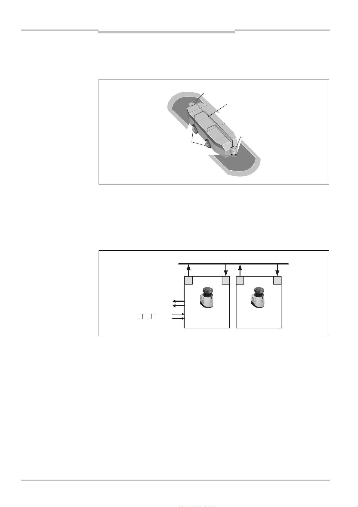
3.2 Function expansion by connecting ESPE
By connecting together individual ESPE via EFI additional applications become possible.
Example 1: Two S300 in host/guest operation
vehicle monitoring for bidirectional travel
3
4
The S300 safety laser scanners are connected to a host/guest system via an EFI connection. It is then possible, for instance, to realize vehicle monitoring in two directions of
movement.
The guest (2) receives the incremental encoder values (4) from the host (1) over the EFI
interface (3). It monitors the areas for the second direction of travel as a function of the
velocity. As soon as there is an object in the protective field, it switches the OSSDs on the
host via the EFI interface to the OFF state (5).
host/guest system
5
Advantages:
• less configuration effort:
– central interface for the configuration of the system
– concurrent monitoring case switching
• less wiring costs:
– The cables for the input signals only need to be connected to the host.
– One pair of OSSDs is sufficient for the entire system.
• simplified diagnostics on the host/guest system:
– combined error messages
– central interface for system diagnostics
8 © SICK AG • Industrial Safety Systems • Germany • All rights reserved 8012622/Z098/2016-11-07
Subject to change without notice
Page 9

Technical information Chapter 3
132
Fig.3:
Hazardous point
Fig.4:
Principle of the
EFI
Basics
Example 2: Two C4000 in operation as a cascaded system
protection with presence
detection
Two C4000 safety light curtains form a cascaded system. The C4000 Host (1) performs
the actual hazardous point protection on a press. The C4000 Guest (2) performs the
presence detection. The two C4000 are connected together using EFI. The OSSDs on the
C4000 Host are integrated into the machine controller (4). If the protective field of
the C4000 Guest is interrupted by standing behind or by an attempt at crawling
beneath/reaching under, the OSSDs on the C4000 Host are switched via EFI (3) to the
OFF state.
cascaded C4000 system
4
Advantages:
• Up to three safety light curtains can be connected to each other.
• No additional external circuitry required. Quick to connect.
• Resolution and protective field height may differ among the individual systems.
8012622/Z098/2016-11-07 © SICK AG • Industrial Safety Systems • Germany • All rights reserved 9
Subject to change without notice
Page 10
Chapter 3 Technical information
3
4
Fig.5:
Access protection with
Fig.6:
Principle of the
Basics
EFI
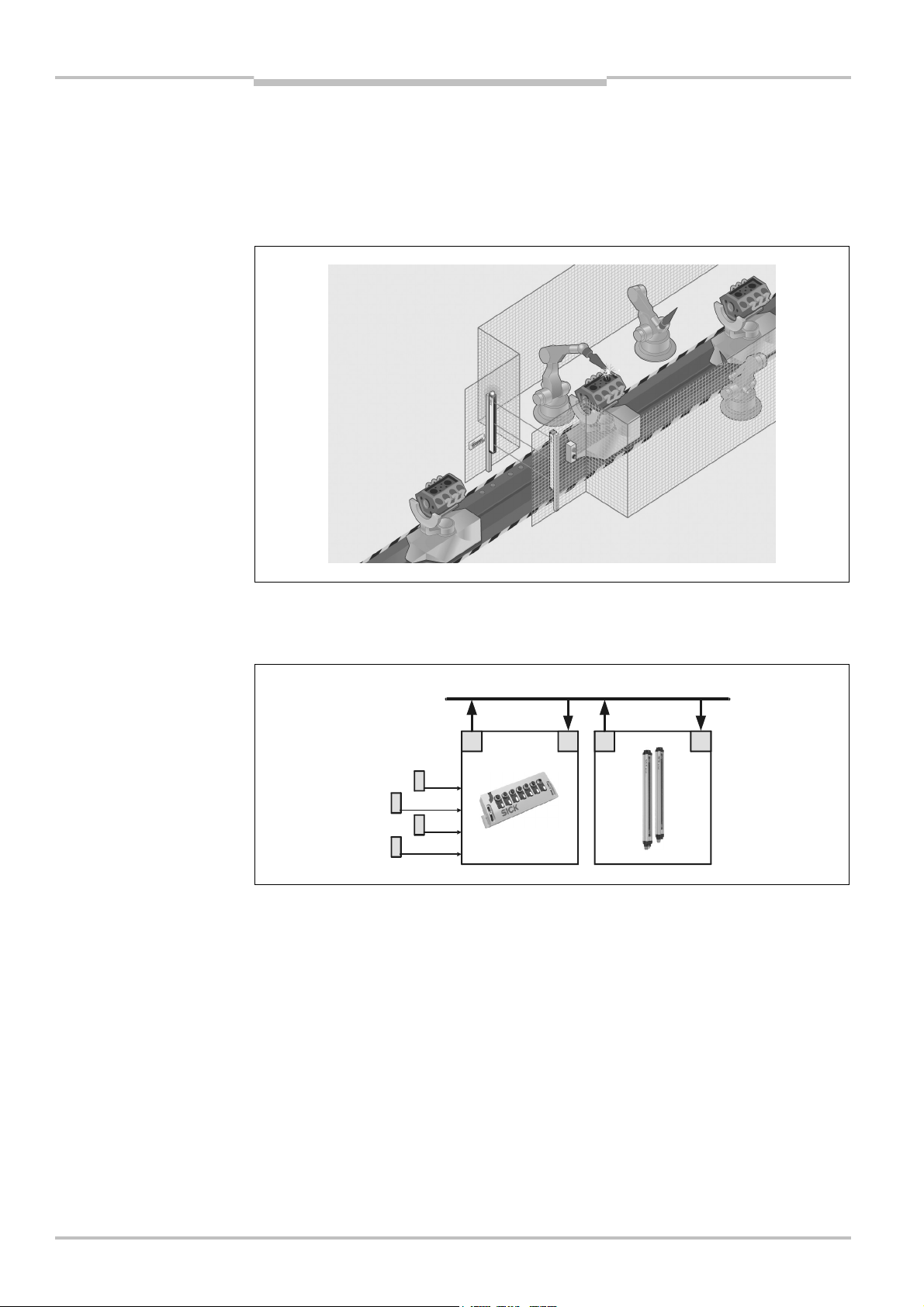
3.3 Function expansion using switching amplifiers
Using the UE402 switching amplifiers for C4000 and UE403 for M4000 the functionality of
the C4000 safety light curtains and the M4000 multiple light beam safety devices can be
expanded.
Example: Muting with M4000 and UE403
muting
M4000 muting system
Two pairs of inductive muting sensors (1) connected to the UE403 detect the transport
platform. The UE403 switching amplifier (2) transmits signals via EFI (3) to the M4000
multiple light beam safety device (4) and controls the muting function.
2
1
Advantages:
• less wiring due to local connection of all signals
• less wiring between switching amplifier and ESPE due to EFI
10 © SICK AG • Industrial Safety Systems • Germany • All rights reserved 8012622/Z098/2016-11-07
Subject to change without notice
Page 11
Technical information Chapter 3
3
Fig.7:
Safety application with
Fig.8:Simultaneous
EFI
Basics
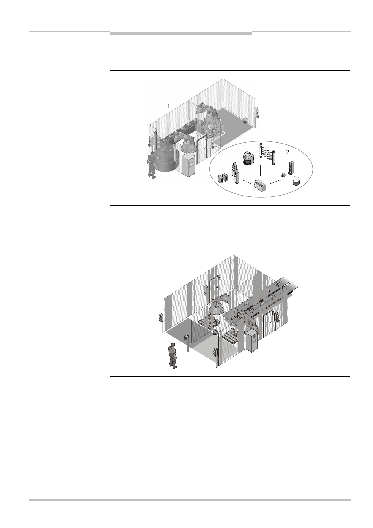
3.4 Applications with safety controllers
Complex safety applications can be solved specifically using safety controllers.
a Flexi Soft safety controller
protective field monitoring
with S3000 and a safety
controller
In the insertion station with rotary table shown and the downstream robot station (1) all
the safety-related functions (hazardous point protection, hazardous area protection, door
contacts, emergency stop, restart) are realized using a Flexi Soft safety controller (2). The
ESPE are integrated into the safety application via EFI.
1
2
One S3000 simultaneously monitors two protective fields (1 and 2). Via EFI it signals the
states of the protective fields to the Flexi Soft safety controller (3). The safety controller
has two OSSDs for separate safe shut down. The related industrial robot is shut down by
an object in one of the protective fields. The second station continues to operate.
Advantages:
• all safety-relevant functions in one application
• one ESPE saved due to simultaneous protective field monitoring
• increased availability of the system, as only the robots related to the hazardous
situation are stopped and not the complete system
8012622/Z098/2016-11-07 © SICK AG • Industrial Safety Systems • Germany • All rights reserved 11
Subject to change without notice
Page 12
Chapter 3 Technical information
Fig.9:
Integration of two
Basics
EFI
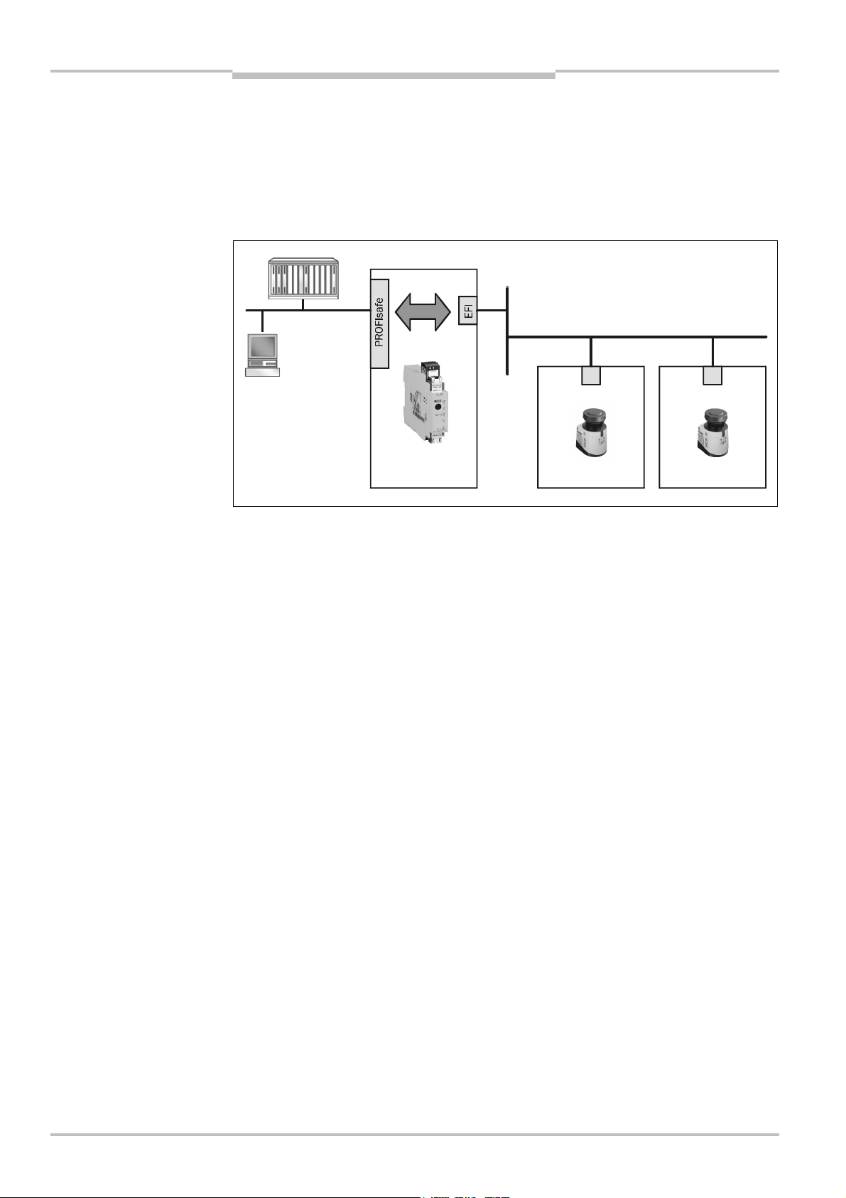
3.5 Network solutions
By integrating ESPE with the aid of the EFI gateway it is possible to bidirectionally transmit
configuration, status and diagnostics functions from the ESPE to the bus system
PROFINET IO PROFIsafe.
Using the EFI gateway, one or more ESPE or even entire applications realized with safety
controllers can be integrated into, for example, an (F)PLC.
S300 in host/guest operation
into a bus system
12 © SICK AG • Industrial Safety Systems • Germany • All rights reserved 8012622/Z098/2016-11-07
Subject to change without notice
Page 13
Technical information Chapter 4
Fig.10:
Safety controller with
EFI
Technical realization
4 Technical realization
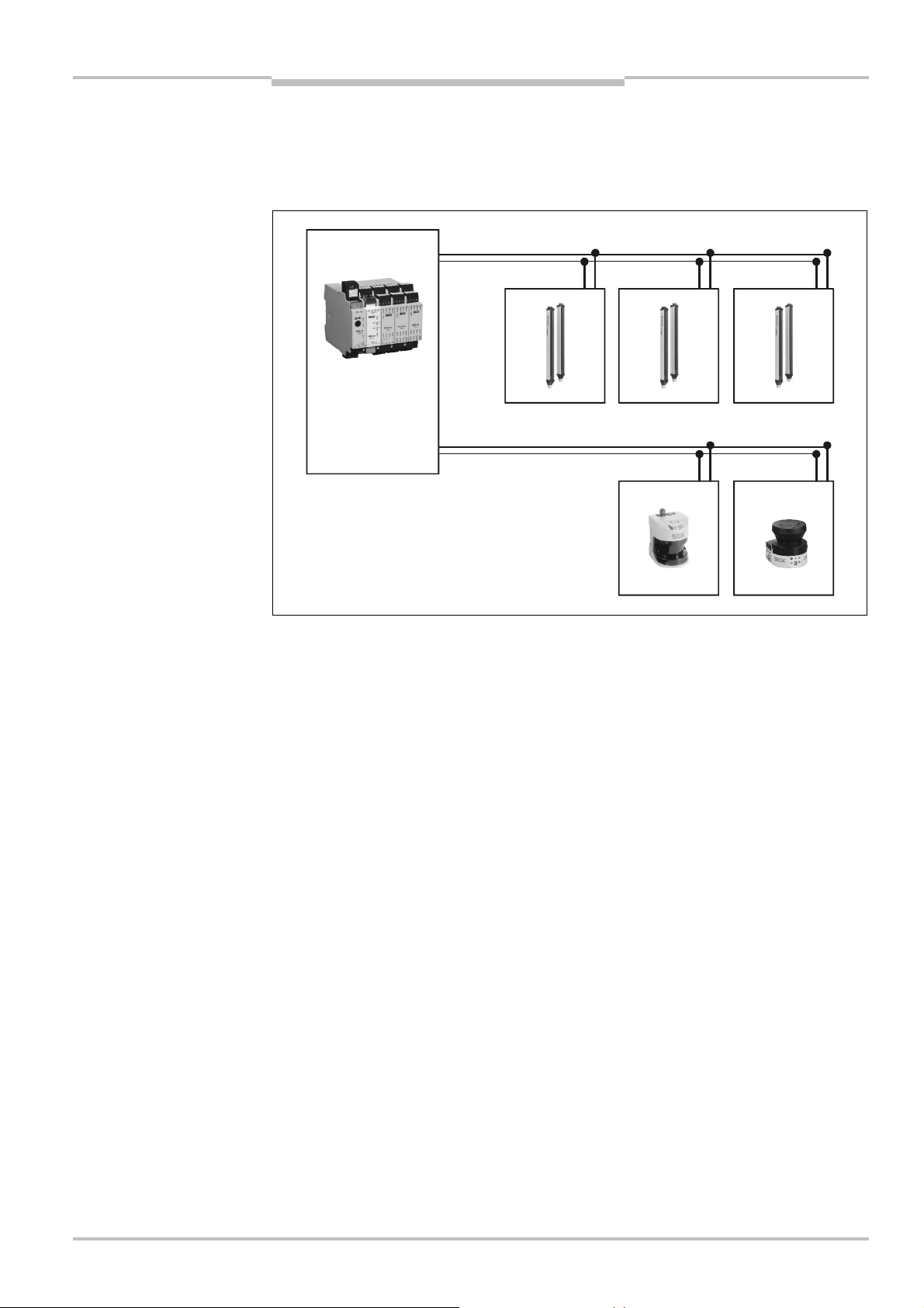
EFI is a linear bus system. Up to four devices can be connected to this bus system. The
actual number of devices depends on the related application or product family.
ESPE connected via two EFI
strings
Twisted-pair cable with a characteristic impedance of 108 … 132 Ω is used as the bus
medium (see also chapter 6 “Technical specifications” on page 54).
8012622/Z098/2016-11-07 © SICK AG • Industrial Safety Systems • Germany • All rights reserved 13
Subject to change without notice
Page 14
Chapter 4 Technical information
8
887
Fig.11:
Example data
Fig.12:
Example data
Technical realization
EFI
4.1 Data exchange via EFI
To enable data to be exchanged via EFI, each device connected has a unique address.
exchange between two
S3000
7
7
In the example the S3000 Host has the address 7, the S3000 Guest the address 8. The
host receives via address 8 the status information on the OSSDs and the diagnostics
messages from the guest on contamination. The guest however receives the incremental
encoder values from the host over the address 7.
The safety controllers receive via these addresses status information on the
electrosensitive protective devices (C4000, S3000 etc.) or they control functions on the
ESPE via these addresses (muting, operating mode switching etc.).
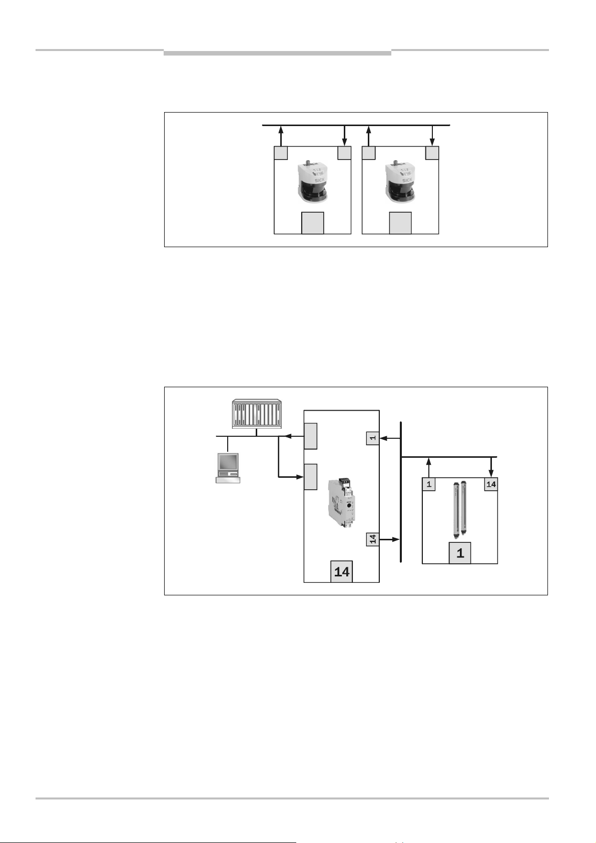
If an EFI system is connected via an EFI gateway to a PROFINET IO, these data can be
forwarded to an (F)PLC or control tasks performed by the (F)PLC.
exchange between an (F)PLC
and an M4000 via an EFI
gateway
In the example the (F)PLC can write data to the M4000 via the routing in the EFI gateway
(address 14). I.e. muting signals can be simulated by the control system. Conversely,
status information including the output information from the M4000 (address 1) can be
transferred to the (F)PLC via the routing in the EFI gateway.
14 © SICK AG • Industrial Safety Systems • Germany • All rights reserved 8012622/Z098/2016-11-07
Subject to change without notice
Page 15

Technical information Chapter 4
Tab.1:
Product family
EFI
Technical realization
4.1.1 Addressing
The SICK product families have the following addresses on the EFI:
addresses on the EFI
Notes
Product families Device address
C4000 receiver (Host) 1
C4000 receiver (Guest 1) 2
C4000 receiver (Guest 2) 3
C4000 sender (Host) 4
C4000 sender (Guest 1) 5
C4000 sender (Guest 2) 6
M4000 receiver 1
M4000 sender 4
S3000 (Host/Guest) 7/8
S300 (Host/Guest) 7/8
S300 Mini (Host/Guest) 7/8
UE402 14
UE403 11/12/13/14
Flexi Soft FX3-CPU1, -CPU2, -CPU3 11/12/13/14
UE4740 EFI gateway 13/14
• Devices with the same address cannot be operated on the EFI at the same time.
• If there are several C4000 safety light curtains on the EFI string, the addresses for the
cascaded system are assigned automatically.
The addresses are saved in non-volatile memory in the device memory in the C4000.
The device can no longer be used as a standalone device or in a different system
position.
Reset the system position saved in the C4000 using the CDS configuration software or
using the Host-Guest Plug available as an accessory.
• In an EFI system with two safety laser scanners, set the address of one of the scanners
to guest! The procedure for addressing is described in the related operating instructions
in the chapter “Electrical installation” (S300 Mini, S300, S3000).
• For the UE4740 EFI gateway, the UE403 and the Flexi Soft FX3-CPU1, -CPU2, -CPU3 the
EFI device address can be modified using CDS or Flexi Soft Designer.
To change the addresses of the EFI gateway, connect to the EFI gateway in the CDS.
Right click the symbol for the EFI gateway and on the context menu choose Operate
service/gateway with control system.
To change the addresses of the Flexi Soft FX3-CPU1, -CPU2, -CPU3, connect to the Flexi
Soft Designer and the CPU. Right click the symbol for the CPU, a menu then appears
where you can select the required EFI device address.
8012622/Z098/2016-11-07 © SICK AG • Industrial Safety Systems • Germany • All rights reserved 15
Subject to change without notice
Page 16

Chapter 4 Technical information
Tab.2:
Maximum number of
Technical realization
EFI
4.1.2 Sending and receiving of information
Send
Each device sends exactly one item of status information with a length of up to 26 bits of
data (C4000 and M4000 senders do not provide any information, this is provided by the
C4000 or M4000 receivers).
The status information is not addressed to a specific user on the EFI string, i.e. all users on
the EFI string can receive the status information.
Receive
The product families differ in the number of items of status information received.
The maximum number of items of status information received and their addresses are
listed in the following table by product family. The table shows the items of status
information received per EFI string.
items of status information
received
Product family
Device
address
Max. number of items
of status information
received
Device addresses from
which items of status
information are received
M4000 receiver 1 1 11, 12, 13 or 14
C4000 receiver (Host) 1 3 2, 3 and 14
C4000 receiver (Guest 1) 2 – –
C4000 receiver (Guest 2) 3 – –
S3000 (Host) 7 1 8, 13 or 14
S3000 (Guest) 8 1 7, 13 or 14
S300 (Host) 7 1 8, 13 or 14
S300 (Guest) 8 1 7, 13 or 14
S300 Mini (Host) 7 1 13 or 14
S300 Mini (Guest) 8 1 7, 13 or 14
UE402 14 1 1
UE403 14 1 1
Flexi Soft FX3-CPU1, -CPU2,
11-14 3 1-8, 11-14
-CPU3
UE4740 EFI gateway 13/14 3 1-8, 13/14
16 © SICK AG • Industrial Safety Systems • Germany • All rights reserved 8012622/Z098/2016-11-07
Notes
• The maximum number of items of status information received defines the number of
devices from which a device can receive information (e.g. C4000 Host from the two
guests and a safety controller).
• The devices addresses in column 4 define the devices to which a device can be
connected. The C4000 Host receives, e.g., only the addresses 2 and 3 (C4000 Guests)
and 14 (safety controllers or EFI gateways). The connection of an M4000 (1) or an
S3000 (7) is not possible.
• Also pay attention to the information given in section 4.2 “Firmware compatibility of the
EFI devices” on page 17.
Subject to change without notice
Page 17

Technical information Chapter 4
Tab.3:
Firmware
Technical realization
EFI
4.2 Firmware compatibility of the EFI devices
The following tables show which ESPE can be connected to which device.
4.2.1 C4000 safety light curtain
compatibility
C4000/UE devices
C4000 receiver C4000 sender
C4000 Advanced
C4000 Standard
C4000 Guest
C4000 Guest
C4000 Advanced
C4000 Standard
C4000 Strd./Adv.
C4000 Guest
C4000 Strd./Adv.
Flexi Soft V1.00
UE4740 V1.11
UE402 V1.10
UE403 –
Legend
Possible
Not possible
On request
?
C4000 Advanced
C4000 Standard
C4000 Advanced
C4000 Standard
C4000 Advanced
C4000 Standard
C4000 Entry/Exit
Firmware
V3.31
V3.31
V3.31
V3.31
V3.31
V3.31
V5.05
?
?
?
C4000 Palletizer
C4000 Palletizer II
C4000 Fusion
C4000 Guest
Firm-
V5.05
V6.11
ware
V7.21
V3.33
V1.00
V1.11
C4000 Standard/Advanced
C4000 Standard/Advanced
V6.00
V6.00
–
–
C4000 Standard/Advanced
C4000 Entry/Exit
C4000 Palletizer
V6.00
V6.00
V6.00
8012622/Z098/2016-11-07 © SICK AG • Industrial Safety Systems • Germany • All rights reserved 17
Subject to change without notice
Page 18

Chapter 4 Technical information
Tab.4:
Firmware
Technical realization
EFI
4.2.2 M4000 multiple light beam safety device
M4000 receiver M4000 sender
compatibility
M4000/UE devices
UE403
M4000 Advanced
M4000 Advanced Curtain
M4000 Advanced A/P
Firmware
Flexi Soft V1.11
UE4740 V1.12
UE402 –
UE403 V1.51
M4000 Area
V1.50 V1.50
M4000 Advanced
M4000 Advanced Curtain
M4000 Advanced A/P
M4000 Area
Firmware
V1.00
V1.11
–
–
M4000 Advanced Curtain
V1.10 V1.10 V1.10
M4000 Advanced
M4000 Area
Legend
Possible
Not possible
18 © SICK AG • Industrial Safety Systems • Germany • All rights reserved 8012622/Z098/2016-11-07
Subject to change without notice
Page 19

Technical information Chapter 4
Tab.5:
Firmware compatibi
-
Tab.6:
Bytes of the EFI
Technical realization
EFI
4.2.3 S300/S3000 safety laser scanners
lity S300/S3000/UE devices
Standalone device
on an EFI partner device
Guest
Host/Guest
on an EFI partner device
S3000 Anti Collision
S3000
S3000 Coldstore
S300
S300
S300 Mini Remote
S300 Mini Remote, S3000 or S300
S3000, S300, S300 Mini Remote
S300, S300 Mini Remote
communication
Note
S3000 in compatibility mode
S3000 Coldstore in compatibility mode
S300 in compatibility mode
S3000 in compatibility mode
S3000 Coldstore in compatibility mode
S300 i in compatibility mode
S300 Mini Remote
S300
S3000 Coldstore
S3000 Anti Collision
Flexi Soft V1.00
UE4740 V1.11
UE402 –
UE403 –
S3000
V1.11
V1.11
Host
S3000 Anti Collision
S3000
S3000 Coldstore
S300
S3000 or S300
–
–
Legend
Possible
Not possible
Compatibility with the S3000 is provided if the sensor head as well as the I/O module have
a serial number of 1221XXX or later.
4.3 Description of the bytes and bits of the EFI communication
4.3.1 Bytes of the EFI communication
Byte Description
Byte 0 General data
Byte 1 General and device-specific data
S300 Mini Remote
S3000 Expert
S3000
S300
8012622/Z098/2016-11-07 © SICK AG • Industrial Safety Systems • Germany • All rights reserved 19
Subject to change without notice
Byte 2 Device specific data
Byte 3 Device specific data
Byte 4 CRC LB
Byte 5 CRC HB
1)
CRC (covers data and device code) Low Byte.
2)
CRC ( covers data and device code) High Byte.
1)
2)
Page 20

Chapter 4 Technical information
Technical realization
EFI
Description of bit 0 to 7 of byte 0
Byte 0 0.0
3)
General Dynamic
Counter
C4000 receiver Dynamic
Counter
M4000 receiver Dynamic
Counter
S3000 in
compatibility
4)
mode
Dynamic
Counter
S3000 Dynamic
Counter
S3000 Anti
Collision
S300 in
compatibility
4)
mode
Dynamic
Counter
Dynamic
Counter
S300 Dynamic
Counter
S300 Mini Dynamic
Counter
UE402 Dynamic
Counter
UE403 Dynamic
Counter
UE4740 Dynamic
Counter
Flexi Soft Dynamic
Counter
Tab. 7: Byte 0 of the EFI communication
3)
0.1
Dynamic
Counter
Dynamic
Counter
Dynamic
Counter
Dynamic
Counter
Dynamic
Counter
Dynamic
Counter
Dynamic
Counter
Dynamic
Counter
Dynamic
Counter
Dynamic
Counter
Dynamic
Counter
Dynamic
Counter
Dynamic
Counter
3)
0.2
Dynamic
Counter
Dynamic
Counter
Dynamic
Counter
Dynamic
Counter
Dynamic
Counter
Dynamic
Counter
Dynamic
Counter
Dynamic
Counter
Dynamic
Counter
Dynamic
Counter
Dynamic
Counter
Dynamic
Counter
Dynamic
Counter
0.3 0.4 0.5 0.6 0.7
OSSD1 OSSD2 Warning
Field 1
OSSD1 (HW
OSSD State)
OSSD2
(virtual)
Not used Weak
Weak
(pollution
warning)
(pollution
Reset Switch
Input (button
pressed)
Reset Switch
Input
warning)
OSSD1 (HW
OSSD State)
OSSD2
(virtual)
Not used Weak
(pollution
warning)
Reset Switch
Input
≥V01.20
Reset/RES/
OVR Switch
Input (MI2)
OSSD
S3000_1
OSSD
S3000_2
Status
Warning
Field
OSSD Speed Valid Status
Warning
Field 1
Weak
(pollution
warning)
Weak
(pollution
warning)
OSSD Speed Valid Not used Weak
(pollution
Reset (button
pressed)
Reset (button
pressed)
Reset (button
pressed)
warning)
OSSD
S300_1
OSSD
S300_2
Status
Warning
Field 1
OSSD Speed Valid Status
Warning
Field
Not used Not used Status
Warning
Field
0 0 Input Pin B1
conditional
Override
(identical to
bit info tech
in terminal
status)
0 0 Not used
(Input Pin B1
Bypass)
Weak
(pollution
warning)
Weak
(pollution
warning)
Weak
(pollution
warning)
Input Pin B2
conditional
Override
(identical to
bit info tech
in terminal
status)
Not used
(Input Pin B2
Bypass)
Reset (button
pressed)
Reset (button
pressed)
Not used
0
RES/OVR
Switch Input
(UI2)
Byte 0, Bit 3 Byte 0, Bit 4 Byte 0, Bit 5 Byte 0, Bit 6 Byte 0, Bit 7
Byte 0, Bit 3 Byte 0, Bit 4 Byte 0, Bit 5 Byte 0, Bit 6 Byte 0, Bit 7
3)
Bit is device internal predefined. Read only.
4)
For information on the compatibility mode see the operating instructions for the devices.
20 © SICK AG • Industrial Safety Systems • Germany • All rights reserved 8012622/Z098/2016-11-07
Subject to change without notice
Page 21

Technical information Chapter 4
Technical realization
EFI
Description of bit 0 to 7 of byte 1
Byte 1 1.0 1.1
General Reset
5)
I/O error Diagnostic
Required
(Reset Lamp)
C4000 receiver Reset
I/O error Diagnostic
Required
State
M4000 receiver Reset
I/O error Diagnostic
Required
State
S3000 in
compatibility
7)
mode
Reset
Required
(Reset Lamp)
S3000 Reset
I/O error Diagnostic
I/O error Diagnostic
Required
(Reset Lamp)
S3000 Anti
Collision
S300 in
compatibility
7)
mode
Reset
Required
(Reset Lamp)
Reset
Required
(Reset Lamp)
S300 Reset
I/O error Diagnostic
I/O error Diagnostic
I/O error Diagnostic
Required
(Reset Lamp)
S300 Mini Not used I/O error Not used Not used Not used Not used Not used Not used
UE402 0 I/O error Diagnostic
UE403 Muting/Over-
I/O error Diagnostic
ride Lamp
Error Status
UE4740 Byte 1, Bit 0 Byte 1, Bit 1
(I/O Error)
Flexi Soft Byte 1, Bit 0 Byte 1, Bit 1
(I/O Error)
Tab. 8: Byte 1 of the EFI communication
6)
1.2
classification
classification
classification
classification
classification
classification
classification
classification
classification
classification
Diagnostic
classification
Diagnostic
classification
6)
1.3
Diagnostic
classification
Diagnostic
classification
Diagnostic
classification
Diagnostic
classification
Diagnostic
classification
Diagnostic
classification
Diagnostic
classification
Diagnostic
classification
Diagnostic
classification
Diagnostic
classification
Diagnostic
classification
Diagnostic
classification
1.4 1.5 1.6 1.7
Specific
device data
Specific
device data
Specific
device data
Specific
device data
User Modes User Modes User Modes EStop status
Not used Not used Not used C1/CBS
Switch Input
(MI1)
Input Pin A1 Input Pin A2 Input Pin B1 Input Pin B2
Input Pin A1 Input Pin A2 Input Pin B1 Input Pin B2
Input Pin A1 Input Pin A2 Input Pin B1 Input Pin B2
Input Pin A1 Input Pin A2 Input Pin B1 Input Pin B2
Input Pin A1/
Input Pin C1
Input Pin A2/
8)
Input Pin C2
Input Pin B1 Input Pin B2
8)
Input Pin A1 Input Pin A2 Input Pin A3 Input Pin A4
Not used
(Input Pin A1)
Not used
(Input Pin A2)
Not used
(Input Pin A3)
Not used
(Input Pin A4)
Byte 1, Bit 4 Byte 1, Bit 5 Byte 1, Bit 6 Byte 1, Bit 7
Byte 1, Bit 4 Byte 1, Bit 5 Byte 1, Bit 6 Byte 1, Bit 7
5)
The bit cannot be freely used.
6)
Bit is device internal predefined. Read only.
7)
For information on the compatibility mode see the operating instructions for the devices.
8)
Configuration dependent: Without speed routing/with speed routing.
8012622/Z098/2016-11-07 © SICK AG • Industrial Safety Systems • Germany • All rights reserved 21
Subject to change without notice
Page 22

Chapter 4 Technical information
Technical realization
EFI
Description of bit 0 to 7 of byte 2
Byte 2 2.0 2.1 2.2 2.3 2.4 2.5 2.6 2.7
General Specific
device data
C4000 receiver Teach-In
active
M4000 receiver Not used Not used Not used Not used Not used Not used Not used Not used
S3000 in
compatibility
7)
mode
Input Pin C1 Input Pin C2 Input Pin D1 Input Pin D2 Not used Not used Not used Not used
S3000 Input Pin C1/
Speed Bit 0
S3000 Anti
Collision
S300 in
compatibility
7)
mode
Input Pin C1/
Speed Bit 0
Input Pin C1 Input Pin C2 Not used Not used Not used Not used Not used Not used
S300 Input Pin C1/
Speed Bit 0
S300 Mini Not used Not used Not used Not used Not used Not used Not used Not used
UE402 Input Pin A5 Input Pin A6 Input Pin A7 Input Pin A8 0 0 0 0
UE403 Not used
(Input Pin A5)
UE4740 Byte 2, Bit 0 Byte 2, Bit 1 Byte 2, Bit 2 Byte 2, Bit 3 Byte 2, Bit 4 Byte 2, Bit 5 Byte 2, Bit 6 Byte 2, Bit 7
Flexi Soft Byte 2, Bit 0 Byte 2, Bit 1 Byte 2, Bit 2 Byte 2, Bit 3 Byte 2, Bit 4 Byte 2, Bit 5 Byte 2, Bit 6 Byte 2, Bit 7
Tab. 9: Byte 2 of the EFI communication
Specific
device data
Key-Switch
state
Input Pin C2/
9)
Speed Bit 1
Input Pin C2/
9)
Speed Bit 1
Input Pin C2/
9)
Speed Bit 1
Not used
(Input Pin A6)
Specific
device data
Take
snapshot
Input Pin D1/
9)
Speed Bit 2
Input Pin D1/
9)
Speed Bit 2
Speed Bit 2 Speed Bit 3 Speed Bit 4 Speed Bit 5 Speed Bit 6 Speed Bit 7
9)
Not used
(Input Pin A7)
Specific
device data
Field status
(red/green)
Input Pin D2/
9)
Speed Bit 3
Input Pin D2/
9)
Speed Bit 3
Not used
(Input Pin A8)
Specific
device data
Specific
device data
Specific
device data
Field status Field status EStop
Channel 1
Speed Bit 4 Speed Bit 5 Speed Bit 6 Speed Bit 7
9)
Speed Bit 4 Speed Bit 5 Speed Bit 6 Speed Bit 7
9)
Muting
Sensor A1
Muting
Sensor A2
Muting
Sensor B1
Specific
device data
EStop
Channel 2
Muting
Sensor B2
9)
Configuration dependent: Without speed routing/with speed routing.
22 © SICK AG • Industrial Safety Systems • Germany • All rights reserved 8012622/Z098/2016-11-07
Subject to change without notice
Page 23

Technical information Chapter 4
Technical realization
EFI
Description of bit 0 to 7 of byte 3
Byte 3 3.0 3.1 3.2 3.3 3.4 3.5 3.6 3.7
General
C4000 receiver
M4000 receiver
S3000 in
compatibility
11)
mode
S3000
S300 Anti
Collision
S300 in
compatibility
11)
mode
S300
S300 Mini
UE402
UE403
UE4740
Flexi Soft
Tab. 10: Byte 3 of the EFI communication
Specific
device data
10)
ADO
10)
ADO
Not used Not used Not used Not used Switch off
Specific
device data
CoState
Specific
device data
Specific
device data
Not used Not used Not used Not used Virtual
Bypass State
Not used Muting State Muting Lamp
status
Specific
device data
Delivery
Status Flag
1. monitoring
area
Specific
device data
PU Data
Valid Flag
Status
Warning
Field
1. monitoring
Specific
device data
photoelectric
switch 2
Mode Switch
state on PU
Switch off
2. monitoring
area
Specific
device data
Virtual
photoelectric
switch 1
Select Switch
state on PU
Status
Warning Field
2. monitoring
area
area
12)
13)
Warning
Field 2/Sim.
Protective
Field 2/
Warning
12)
Field 2
Sim. Collision
Protection
Field 1/
Collision
protection
13)
field 2
Speed Bit 8 Speed Bit 9 Speed Bit 10 Speed Bit 11 Protective
Field 1/
Protective
Field 1/
Protective
12)
Field 1
Speed Bit 8 Speed Bit 9 Speed Bit 10 Speed Bit 11 Protective
Field 1/
Protective
13)
Field 1
Not used Not used Not used Not used Switch off
1. monitoring
area
Warning
Field 1/
Protective
Field 2/
Warning
12)
Field 1
Collision
Protection
Field 1 /
Collision
Protection
13)
Field
Status
Warning
Field
Sim.
Protective
Field 1/Sim.
Protective
Field 1/–
Sim.
Protective
Field 1/–
Not used Not used
1. monitoring
area
Speed Bit 8 Speed Bit 9 Speed Bit 10 Speed Bit 11 Protective
Field 1
Not used Not used Not used Not used Protective
Field 1
Warning
Field 1
Warning
Field 1
Not used Warning
Field 2
Not used Warning
Field 2
Lock-out Info Lock-out Info Lock-out Info Lock-out Info Input Pin B1 Input Pin B2 Input Pin B3 Input Pin B4
Not used Not used Not used Not used C1/CBS/OVR
Switch Input
(UI1)
Byte 3, Bit 0 Byte 3, Bit 1 Byte 3, Bit 2 Byte 3, Bit 3 Byte 3, Bit 4 Byte 3, Bit 5 Byte 3, Bit 6 Byte 3, Bit 7
Byte 3, Bit 0 Byte 3, Bit 1 Byte 3, Bit 2 Byte 3, Bit 3 Byte 3, Bit 4 Byte 3, Bit 5 Byte 3, Bit 6 Byte 3, Bit 7
10)
ADO can be used for non-safety-related evaluations, e.g. weak signal output.
11)
For information on the compatibility mode see the operating instructions for the devices.
12)
Dual (1 protective field, 1 warning field)/Dual protective fields (2 protective fields)/Triple (1 protective field,
2 warning fields).
13)
Dual collision protection (1 protective field, 1 collision protection field)/Triple collision protection (1 protective
field, 2 collision protection fields)
8012622/Z098/2016-11-07 © SICK AG • Industrial Safety Systems • Germany • All rights reserved 23
Subject to change without notice
Page 24

Chapter 4 Technical information
Technical realization
EFI
Description of bit 0 to 7 of byte 4
Byte 4 4.0 4.1 4.2 4.3 4.4 4.5 4.6 4.7
General CRC
C4000 receiver CRC
M4000 receiver CRC
S3000 in
compatibility
15)
mode
S3000 CRC
S3000 Anti
Collision
S300 in
compatibility
15)
mode
S300 CRC
S300 Mini CRC
UE402 CRC
UE403 CRC
UE4740 CRC
Flexi Soft CRC
Low Byte
Low Byte
Low Byte
CRC
Low Byte
Low Byte
CRC
Low Byte
CRC
Low Byte
Low Byte
Low Byte
Low Byte
Low Byte
Low Byte
Low Byte
Tab. 11: Byte 4 of the EFI communication
CRC
14)
Low Byte
CRC
Low Byte
CRC
Low Byte
CRC
Low Byte
CRC
Low Byte
CRC
Low Byte
CRC
Low Byte
CRC
Low Byte
CRC
Low Byte
CRC
Low Byte
CRC
Low Byte
CRC
Low Byte
CRC
Low Byte
CRC
Low Byte
CRC
Low Byte
CRC
Low Byte
CRC
Low Byte
CRC
Low Byte
CRC
Low Byte
CRC
Low Byte
CRC
Low Byte
CRC
Low Byte
CRC
Low Byte
CRC
Low Byte
CRC
Low Byte
CRC
Low Byte
CRC
Low Byte
CRC
Low Byte
CRC
Low Byte
CRC
Low Byte
CRC
Low Byte
CRC
Low Byte
CRC
Low Byte
CRC
Low Byte
CRC
Low Byte
CRC
Low Byte
CRC
Low Byte
CRC
Low Byte
CRC
Low Byte
CRC
Low Byte
CRC
Low Byte
CRC
Low Byte
CRC
Low Byte
CRC
Low Byte
CRC
Low Byte
CRC
Low Byte
CRC
Low Byte
CRC
Low Byte
CRC
Low Byte
CRC
Low Byte
CRC
Low Byte
CRC
Low Byte
CRC
Low Byte
CRC
Low Byte
CRC
Low Byte
CRC
Low Byte
CRC
Low Byte
CRC
Low Byte
CRC
Low Byte
CRC
Low Byte
CRC
Low Byte
CRC
Low Byte
CRC
Low Byte
CRC
Low Byte
CRC
Low Byte
CRC
Low Byte
CRC
Low Byte
CRC
Low Byte
CRC
Low Byte
CRC
Low Byte
CRC
Low Byte
CRC
Low Byte
CRC
Low Byte
CRC
Low Byte
CRC
Low Byte
CRC
Low Byte
CRC
Low Byte
CRC
Low Byte
CRC
Low Byte
CRC
Low Byte
CRC
Low Byte
CRC
Low Byte
CRC
Low Byte
CRC
Low Byte
CRC
Low Byte
CRC
Low Byte
CRC
Low Byte
CRC
Low Byte
CRC
Low Byte
CRC
Low Byte
CRC
Low Byte
14)
CRC (covers data and device code) Low Byte.
15)
For information on the compatibility mode see the operating instructions for the devices.
24 © SICK AG • Industrial Safety Systems • Germany • All rights reserved 8012622/Z098/2016-11-07
Subject to change without notice
Page 25

Technical information Chapter 4
Technical realization
EFI
Description of bit 0 to 7 of byte 5
Byte 5 5.0 5.1 5.2 5.3 5.4 5.5 5.6 5.7
General CRC
High Byte
C4000 receiver CRC
High Byte
M4000 receiver CRC
High Byte
S3000 in
compatibility
17)
mode
CRC
High Byte
S3000 CRC
Low Byte
S3000 Anti
Collision
S300 in
compatibility
17)
mode
CRC
Low Byte
CRC
High Byte
S300 CRC
Low Byte
S300 Mini CRC
Low Byte
UE402 CRC
High Byte
UE403 CRC
High Byte
UE4740 CRC
High Byte
Flexi Soft CRC
High Byte
Tab. 12: Byte 5 of the EFI communication
16)
CRC
High Byte
CRC
High Byte
CRC
High Byte
CRC
High Byte
CRC
Low Byte
CRC
Low Byte
CRC
High Byte
CRC
Low Byte
CRC
Low Byte
CRC
High Byte
CRC
High Byte
CRC
High Byte
CRC
High Byte
CRC
High Byte
CRC
High Byte
CRC
High Byte
CRC
High Byte
CRC
Low Byte
CRC
Low Byte
CRC
High Byte
CRC
Low Byte
CRC
Low Byte
CRC
High Byte
CRC
High Byte
CRC
High Byte
CRC
High Byte
CRC
High Byte
CRC
High Byte
CRC
High Byte
CRC
High Byte
CRC
Low Byte
CRC
Low Byte
CRC
High Byte
CRC
Low Byte
CRC
Low Byte
CRC
High Byte
CRC
High Byte
CRC
High Byte
CRC
High Byte
CRC
High Byte
CRC
High Byte
CRC
High Byte
CRC
High Byte
CRC
Low Byte
CRC
Low Byte
CRC
High Byte
CRC
Low Byte
CRC
Low Byte
CRC
High Byte
CRC
High Byte
CRC
High Byte
CRC
High Byte
CRC
High Byte
CRC
High Byte
CRC
High Byte
CRC
High Byte
CRC
Low Byte
CRC
Low Byte
CRC
High Byte
CRC
Low Byte
CRC
Low Byte
CRC
High Byte
CRC
High Byte
CRC
High Byte
CRC
High Byte
CRC
High Byte
CRC
High Byte
CRC
High Byte
CRC
High Byte
CRC
Low Byte
CRC
Low Byte
CRC
High Byte
CRC
Low Byte
CRC
Low Byte
CRC
High Byte
CRC
High Byte
CRC
High Byte
CRC
High Byte
CRC
High Byte
CRC
High Byte
CRC
High Byte
CRC
High Byte
CRC
Low Byte
CRC
Low Byte
CRC
High Byte
CRC
Low Byte
CRC
Low Byte
CRC
High Byte
CRC
High Byte
CRC
High Byte
CRC
High Byte
16)
CRC (covers data and device code) High Byte.
17)
For information on the compatibility mode see the operating instructions for the devices.
8012622/Z098/2016-11-07 © SICK AG • Industrial Safety Systems • Germany • All rights reserved 25
Subject to change without notice
Page 26

Chapter 4 Technical information
Tab.13:
Status information
Technical realization
EFI
4.4 Status information and control options for the EFI devices
Status information and control commands are exchanged between the devices via EFI.
The following tables show the status information that can be accessed and the control
commands that are possible for ESPE, safety controllers as well as EFI gateways.
Note
The information in square brackets reflects the names used in the CDS and in the
Flexi Soft Designer.
4.4.1 C4000 safety light curtain
of the C4000 (data from the
C4000)
Status information Meaning/effect
OSSD on [OSSD]
• Logical 1, if the OSSD of the C4000 is switched
on (green)
• Logical 0, if the OSSD of the C4000 is switched
off (red)
Notes:
Host: In the case of a cascaded system, the
OSSD bit is a group indication for the entire
host/guest or host/guest/guest cascade
Guest 1/guest 2: The OSSD bit corresponds to
the status of the related guest.
Contamination [Weak] • Logical 1, on contamination of the front screen
Reset button pressed [Res. Pressed] • Logical 1, if the reset button is pressed
Reset required [Res. Req.] • Logical 1, if reset required
Status of the emergency stop
[EStop Active]
Logical 1, if the button connected to the
emergency stop input on the C4000 has been
pressed.
Teach-in active [Teach Active]
• Logical 1, if a teach-in key-operated switch
connected to the C4000 has been operated
Note
Status application diagnostic output
18)
(ADO)
[ADO]
• Logical 1, if the configurable application
diagnostic output (ADO) on the C4000 is
signaling, e.g., the contamination status, the
OSSD status or the emergency stop status
Note: The message type depends on the
configuration of the C4000.
Status bypass [Bypass Active]
• Logical 1, if a key-operated pushbutton for
bypass connected to the C4000 has been
operated
Virtual photoelectric switch 2 [VLS2] • Logical 1 = beam unoccupied
• Logical 0 = beam interrupted
Virtual photoelectric switch 1 [VLS1] • Logical 1 = beam unoccupied
• Logical 0 = beam interrupted
With the exception of the OSSD information, all status information always relates to the
safety light curtain polled (host, guest 1 or guest 2).
18)
ADO can be used for non-safety-related evaluations, e.g. weak signal output.
26 © SICK AG • Industrial Safety Systems • Germany • All rights reserved 8012622/Z098/2016-11-07
Subject to change without notice
Page 27

Technical information Chapter 4
Tab.14:
Control features on
EFI
Technical realization
the C4000 (data to the
C4000)
Control feature Meaning/effect
Bypass B1 [In Bypass 1]
• Logical 1, stimulates bit B1 for the key-
operated pushbutton for bypass
Bypass B2 [In Bypass 2]
• Logical 1, stimulates bit B2 for the key-
operated pushbutton for bypass
Operating mode 1 [In A1]
• Logical 1, switches to operating mode 1 of the
C4000
• Logical 0, makes it possible to select a
different operating mode
Operating mode 2 [In A2]
• Logical 1, switches to operating mode 2 of the
C4000
• Logical 0, makes it possible to select a
different operating mode
Operating mode 3 [In A3]
• Logical 1, switches to operating mode 3 of the
C4000
• Logical 0, makes it possible to select a
different operating mode
Operating mode 4 [In A4]
• Logical 1, switches to operating mode 4 of the
C4000
• Logical 0, makes it possible to select a
different operating mode
19)
Operating mode 5 [In A5]
Operating mode 6 [In A6]
Overrun monitoring SCC [In SCC]
Bottom dead center BDC [In BDC]
Top dead center TDC [In TDC]
I/O error [I/O Error]
• Logical 1, switches to operating mode 5 of the
C4000
• Logical 0, makes it possible to select a
different operating mode
• Logical 1, switches to operating mode 6 of the
C4000
• Logical 0, makes it possible to select a
different operating mode
• Logical 1, stimulates the SCC bit for overrun
monitoring on the C4000
• Logical 1, stimulates the BDC bit for PSDI
integration on the C4000
• Logical 1, stimulates the TDC bit for PSDI
integration on the C4000
• Logical 0, if there is no error on a connected
device
• Logical 1, if there is an error on a connected
device
8012622/Z098/2016-11-07 © SICK AG • Industrial Safety Systems • Germany • All rights reserved 27
Subject to change without notice
19)
If two bits are logical 1, there will be an error on the C4000.
Page 28

Chapter 4 Technical information
Tab.15:
Status information
Tab.16:
Control features on
Technical realization
EFI
4.4.2 M4000 multiple light beam safety device
of the M4000 (data from the
M4000)
the M4000 (data to the
M4000)
Status information Meaning/effect
OSSD on [OSSD]
• Logical 1, if the OSSD of the M4000 is
switched on (green)
• Logical 0, if the OSSD of the M4000 is
switched off (red)
Contamination [Weak] • Logical 1, on contamination of the front screen
Reset button pressed [Res. Pressed]
• Logical 1, if the reset button is pressed on the
M4000
Reset required [Res. Req.] • Logical 1, if reset required
Status application diagnostic output
20)
(ADO)
[ADO]
• Logical 1, if the configurable application
diagnostic output (ADO) for the M4000 is
indicating the contamination status or the
OSSD status
Muting status [Muting] • Logical 1, if M4000 muting is active
• Logical 0, if M4000 muting is inactive
Additional signal C1 or Belt
stop [In BS/C1]
Control feature Meaning/effect
Reset/override [In RES/OVR]
• Logical 1, if a function is activated on the
M4000
• Logical 1, stimulates the function configured in
the M4000
Status muting lamp/override lamp
Muting Sensor A1 [In A1]
Muting Sensor A2 [In A2]
Muting Sensor B1 [In B1]
Muting Sensor B2 [In B2]
Override or Additional signal C1 or
Belt stop [In BS/C1]
I/O error [I/O Error]
• Logical 1, stimulates an error message for the
external muting lamp
• Logical 1, stimulates muting sensor A1 for
M4000
• Logical 1, stimulates muting sensor A2 for
M4000
• Logical 1, stimulates muting sensor B1 for
M4000
• Logical 1, stimulates muting sensor B2 for
M4000
• Logical 1, stimulates the related function
configured in the M4000
• Logical 0, if there is no error on a connected
device
• Logical 1, if there is an error on a connected
device
28 © SICK AG • Industrial Safety Systems • Germany • All rights reserved 8012622/Z098/2016-11-07
20)
ADO can be used for non-safety-related evaluations, e.g. weak signal output.
Subject to change without notice
Page 29

Technical information Chapter 4
Tab.17:
Status information
EFI
Technical realization
4.4.3 S3000 safety laser scanner
of the S3000 (data from the
S3000)
Status information Meaning/effect
OSSD on [OSSD]
• Logical 1, if the internal OSSD of the S3000 is
in the ON state (green)
• Logical 0, if the OSSD of the S3000 is in the
OFF state (red)
Warning field bit [WF LED]
• Logical 1, if warning field 1 and warning field 2
of the S3000 are unoccupied or not used
Contamination [Weak] • Logical 1, if the front screen is contaminated
Reset required [Res. Req] • Logical 1, if reset required
Reset button pressed [Res. Pressed]
• Logical 1, if the reset button is pressed on the
S3000
I/O error [I/O Error] • Logical 0, if there is no error on the S3000
• Logical 1, if there is an error on the S3000
Control input A1 [In A1]
• Logical 1, if the connection of control input A1
is HIGH
21)
Note: The control inputs on the S3000 are
used to switch the monitoring cases on the
S3000.
Control input A2 [In A2]
• Logical 1, if the connection of control input A2
is HIGH
21)
Control input B1 [In B1]
Control input B2 [In B2]
Control input C1 [In C1]
Control input C2 [In C2]
Control input D1 [In D1]
Control input D2 [In D2]
Allocated protective field
unoccupied [PF]
• Logical 1, if the connection of control input B1
is HIGH
21)
• Logical 1, if the connection of control input B2
is HIGH
21)
• Logical 1, if the connection of control input C1
is HIGH
21)
• Logical 1, if the connection of control input C2
is HIGH
21)
• Logical 1, if the connection of control input D1
is HIGH
21)
• Logical 1, if the connection of control input D2
is HIGH
21)
• In dual field mode, in dual protective field
mode and in triple field mode and in dual and
triple collision protection mode: Logical 1, if the
active allocated protective field is unoccupied.
8012622/Z098/2016-11-07 © SICK AG • Industrial Safety Systems • Germany • All rights reserved 29
Subject to change without notice
21)
Only if the inputs are activated in the CDS.
Page 30

Chapter 4 Technical information
Technical realization
EFI
Status information Meaning/effect
Allocated warning field unoccupied
[WF]
or
allocated protective field 2
unoccupied [PF2]
Allocated collision protection field
unoccupied [CPF1]
Simultaneous protective field
unoccupied [Sim. PF]
Simultaneous warning field
unoccupied [Sim. WF]
or
simultaneous protective field 2
unoccupied [Sim. PF2]
or
allocated warning field 2
unoccupied [WF2]
Simultaneous collision protection
field unoccupied [Sim. CPF]
or
allocated collision protection field 2
unoccupied [CPF2]
Velocity valid
Velocity
22)
22)
• In dual field mode: Logical 1, if the active
allocated warning field is unoccupied
• In dual protective field mode: Logical 1, if the
active allocated protective field 2 is
unoccupied
• In triple field mode: Logical 1, if the active
allocated warning field is unoccupied
• In dual collision protection mode: Logical 1, if
active allocated collision protection field is
unoccupied
• In triple collision protection field: Logical 1, if
active allocated collision protection field is
unoccupied
• In dual field mode and in dual protective field
mode: Logical 1, if the simultaneously
monitored protective field is unoccupied
• In triple field mode: No function
• In dual collision protection mode: Logical 1, if
the simultaneously monitored protective field is
unoccupied
• In triple collision protection mode: No function
• In dual field mode: Logical 1, if the
simultaneously monitored warning field is
unoccupied
• In dual protective field mode: Logical 1, if the
simultaneously monitored protective field 2 is
unoccupied
• In triple field mode: Logical 1, if the active
allocated warning field 2 is unoccupied
• In dual collision protection field mode:
Logical 1, if the simultaneously monitored
collision protection field is unoccupied
• In triple collision protection mode: Logical 1, if
the active allocated collision protection field 2
is unoccupied
• Logical 1, if a valid velocity is present on the
incremental encoder inputs
• Logical 0, if an invalid velocity is present on the
incremental encoder inputs
• 12 bits for the transmission of the velocity
100000110000 = –2000 cm/s
000000000000 = 0 cm/s
011111010000 = +2000 cm/s
22)
Not in the compatibility mode.
30 © SICK AG • Industrial Safety Systems • Germany • All rights reserved 8012622/Z098/2016-11-07
Subject to change without notice
Page 31

Technical information Chapter 4
Tab.18:
Control f
eatures on
EFI
Technical realization
the S3000 (data to the
S3000)
Control feature Meaning/effect
Static input information A1 [In A1]
• Logical 1, stimulates control input A1 of the
S3000
Static input information A2 [In A2]
• Logical 1, stimulates control input A2 of the
S3000
Static input information B1 [In B1]
• Logical 1, stimulates control input B1 of the
S3000
Static input information B2 [In B2]
• Logical 1, stimulates control input B2 of the
S3000
Static input information C1 [In C1]
• Logical 1, stimulates control input C1 of the
S3000
Static input information C2 [In C2]
• Logical 1, stimulates control input C2 of the
S3000
Static input information D1 [In D1]
• Logical 1, stimulates control input D1 of the
S3000
Static input information D2 [In D2]
• Logical 1, stimulates control input D2 of the
S3000
Static input information E1 [In E1]
23)
• Logical 1, stimulates control input E1 of the
S3000
Static input information E2 [In E2]
23)
• Logical 1, stimulates control input E2 of the
S3000
Stand-by
23)
• Logical 1, stimulates operational status
Stand-by (individually for host and guest)
Velocity valid
23)
• Logical 1, valid velocity is present on the
incremental encoder inputs
• Logical 0, invalid velocity is present on the
incremental encoder inputs
Velocity
23)
• 12 bits for the transmission of the velocity
100000110000 = –2000 cm/s
000000000000 = 0 cm/s
011111010000 = +2000 cm/s
I/O error [I/O Error]
• Logical 0, if there is no error on the connected
partner device
• Logical 1, if there is an error on the connected
partner device
23)
Not in the compatibility mode.
8012622/Z098/2016-11-07 © SICK AG • Industrial Safety Systems • Germany • All rights reserved 31
Subject to change without notice
Page 32

Chapter 4 Technical information
Tab.19:
Status information
Technical realization
EFI
4.4.4 S300 safety laser scanner
of the S300 (data from the
S300)
Status information Meaning/effect
OSSD on [OSSD]
• Logical 1, if the internal OSSD of the S300 is in
the ON state (green)
• Logical 0, if the OSSD of the S300 is in the OFF
state (red)
Warning field bit [WF LED]
• Logical 1, if both warning fields of the S300 are
unoccupied
• Logical 0, if one of the warning fields of the
S300 is infringed
Contamination [Weak] • Logical 1, if the optics cover is contaminated
Reset required [Res. Req] • Logical 1, if reset required
Reset button pressed [Res. Pressed]
• Logical 1, if the reset button is pressed on the
S300
I/O error [I/O Error] • Logical 0, if there is no error on the S300
• Logical 1, if there is an error on the S300
Control input A1 [In A1]
• Logical 1, if the connection of control input A1
is HIGH
Note: The control inputs on the S300 are used
to switch the monitoring cases on the S300.
Control input A2 [In A2]
• Logical 1, if the connection of control input A2
is HIGH
Control input B1 [In B1]
• Logical 1, if the connection of control input B1
is HIGH
Control input B2 [In B2]
• Logical 1, if the connection of control input B2
is HIGH
Control input C1 [In C1]
• Logical 1, if the connection of control input C1
is HIGH
Control input C2 [In C2]
• Logical 1, if the connection of control input C2
is HIGH
Protective field [PF] • Logical 1, if the protective field is unoccupied
Warning field 1 [WF1]
• Logical 1, if the active allocated warning field is
unoccupied
Warning field 2 [WF2]
• Logical 1, if the active allocated warning field is
unoccupied
Velocity valid
24)
• Logical 1, if a valid velocity is present on the
incremental encoder inputs
• Logical 0, if an invalid velocity is present on the
incremental encoder inputs
Velocity
24)
• 12 bits for the transmission of the velocity
100000110000 = –2000 cm/s
000000000000 = 0 cm/s
011111010000 = +2000 cm/s
32 © SICK AG • Industrial Safety Systems • Germany • All rights reserved 8012622/Z098/2016-11-07
24)
Not in the compatibility mode.
Subject to change without notice
Page 33

Technical information Chapter 4
Tab.20:
Control features on
EFI
Technical realization
the S300 (data to the S300)
Control feature Meaning/effect
Static input information A1 [In A1]
• Logical 1, stimulates control input A1 of the
S300
Static input information A2 [In A2]
• Logical 1, stimulates control input A2 of the
S300
Static input information B1 [In B1]
• Logical 1, stimulates control input B1 of the
S300
Static input information B2 [In B2]
• Logical 1, stimulates control input B2 of the
S300
Static input information C1 [In C1]
• Logical 1, stimulates control input C1 of the
S300
Static input information C2 [In C2]
• Logical 1, stimulates control input C2 of the
S300
Static input information D1
25)
[In D1]
Static input information D2
25)
[In D2]
Static input information E1 [In E1]
• Logical 1, stimulates control input D1 of the
S300
• Logical 1, stimulates control input D2 of the
S300
25)
• Logical 1, stimulates control input E1 of the
S300
Static input information E2 [In E2]
25)
• Lo gical 1, stimulates control input E2 of the
S300
Stand-by
25)
• Logical 1, stimulates operational status
Stand-by (individually for host and guest)
Velocity valid
25)
• Logical 1, valid velocity is present on the
incremental encoder inputs
• Logical 0, invalid velocity is present on the
incremental encoder inputs
Velocity
25)
• 12 bits for the transmission of the velocity
100000110000 = –2000 cm/s
000000000000 = 0 cm/s
011111010000 = +2000 cm/s
8012622/Z098/2016-11-07 © SICK AG • Industrial Safety Systems • Germany • All rights reserved 33
Subject to change without notice
I/O error [I/O Error]
25)
Not in the compatibility mode.
• Logical 0, if there is no error on the connected
partner device
• Logical 1, if there is an error on the connected
partner device
Page 34

Chapter 4 Technical information
Tab.21:
Status information
Technical realization
EFI
4.4.5 S300 Mini safety laser scanner
of the S300 Mini (data from
the S300 Mini)
Status information Meaning/effect
Warning field bit [WF]
• Logical 1, if both warning fields of the S300
Mini are unoccupied
• Logical 0, if one of the warning fields of the
S300 Mini is infringed
Protective field [PF] • Logical 1, if the protective field is unoccupied
Warning field 1 [WF1]
• Logical 1, if the active allocated warning field is
unoccupied
Warning field 2 [WF2]
• Logical 1, if the active allocated warning field is
unoccupied
Contamination [Weak] • Logical 1, if the optics cover is contaminated
I/O error [I/O Error] • Logical 0, if there is no error on the S300 Mini
• Logical 1, if there is an error on the S300 Mini
34 © SICK AG • Industrial Safety Systems • Germany • All rights reserved 8012622/Z098/2016-11-07
Subject to change without notice
Page 35

Technical information Chapter 4
Tab.22:
Control features on
EFI
Technical realization
the S300 Mini (data to the
S300 Mini)
Control feature Meaning/effect
Static input information A1 [In A1]
• Logical 1, stimulates control input A1 of the
S300 Mini
Static input information A2 [In A2]
• Logical 1, stimulates control input A2 of the
S300 Mini
Static input information B1 [In B1]
• Logical 1, stimulates control input B1 of the
S300 Mini
Static input information B2 [In B2]
• Logical 1, stimulates control input B2 of the
S300 Mini
Static input information C1 [In C1]
• Logical 1, stimulates control input C1 of the
S300 Mini
Static input information C2 [In C2]
• Logical 1, stimulates control input C2 of the
S300 Mini
Static input information D1 [In D1]
• Logical 1, stimulates control input D1 of the
S300 Mini
Static input information D2 [In D2]
• Logical 1, stimulates control input D2 of the
S300 Mini
Static input information E1 [In E1]
• Logical 1, stimulates control input E1 of the
S300 Mini
Static input information E2 [In E2]
Stand-by
Velocity valid
Velocity
25)
• Logical 1, stimulates control input E2 of the
S300 Mini
• Logical 1, stimulates operational status
Stand-by
• Logical 1 signals a valid velocity being present
on the incremental encoder inputs.
• Logical 0 signals a invalid velocity being
present on the incremental encoder inputs
(velocity in a range that is not configured or
difference allowed between the incremental
encoders exceeded).
• 12 bits for the transmission of the velocity
100000110000 = –2000 cm/s
000000000000 = 0 cm/s
011111010000 = +2000 cm/s
8012622/Z098/2016-11-07 © SICK AG • Industrial Safety Systems • Germany • All rights reserved 35
Subject to change without notice
Page 36

Chapter 4 Technical information
Tab.23:
Status information
Tab.24:Control features on
Technical realization
EFI
4.4.6 Flexi Soft FX3-CPU1, -CPU2, -CPU3 safety controller
on the Flexi Soft (data from
the Flexi Soft)
the Flexi Soft (data to the
Flexi Soft)
Status information Meaning/effect
I/O error [Byte 1, Bit 1]
• Logical 0, if there is no error on the Flexi Soft
CPU
• Logical 1, if there is an error on the Flexi Soft
CPU
Note: This status is to be provided in the
operational status “Executing/Run” on the Flexi
Soft-CPU using programmed logic.
If signals are pre-processed on the Flexi Soft
station and forwarded to EFI users, it is
necessary to program the error states from this
pre-processing as status information. If this
status information is not programmed, it is only
allowed to send signals without pre-processing
to the EFI users.
All except [Byte 1, Bit 1]
• Freely programmable signals correspond to the
requirements for the EFI devices connected
Control feature Meaning/effect
I/O error [Byte 1, Bit 1]
• Logical 0, if there is no error on a connected
device
• Logical 1, if there is an error on a connected
device
Note: Indicates that the data on this EFI
interface are currently invalid and represent
substitute values. This situation occurs, for
example, on EFI gateways if the controlling
(F)PLC is not (yet) operating.
All except [Byte 1, Bit 1]
• Freely useable information for usage in the
Flexi Soft logic.
Note: On the usage of this information the status
of the received I/O error bits is also to be
evaluated.
36 © SICK AG • Industrial Safety Systems • Germany • All rights reserved 8012622/Z098/2016-11-07
Subject to change without notice
Page 37

Technical information Chapter 4
Tab.25:
Status information
Tab.26:
Control features on
EFI
Technical realization
4.4.7 UE4740 EFI gateway
on the EFI gateway (data
from the EFI gateway)
the EFI gateway (data to the
EFI gateway)
Status information Meaning/effect
I/O error [Byte 1, Bit 1] • Logical 0, if there is no error on the EFI gateway
• Logical 1, if there is an error on the EFI gateway
Note: The I/O error is calculated automatically
from the validity of the data on the interfaces
connected and as a function of the usage of the
data (in the gateway routing). Indicates that the
data on this EFI interface are currently invalid
and represent substitute values. This situation
occurs, for example, on EFI gateways if the
controlling (F)PLC is not (yet) operating.
All except [Byte 1, Bit 1]
• Freely programmable signals correspond to the
requirements for the EFI devices connected
Control feature Meaning/effect
I/O error [Byte 1, Bit 1]
• Logical 0, if there is no error on a connected
device
• Logical 1, if there is an error on a connected
device
Note: Indicates that the data on this EFI
interface are currently invalid.
All except [Byte 1, Bit 1]
• Freely useable information for further data
routing.
Note: On the usage of this information the status
of the received I/O error bits is also to be
evaluated.
8012622/Z098/2016-11-07 © SICK AG • Industrial Safety Systems • Germany • All rights reserved 37
Subject to change without notice
Page 38

Chapter 4 Technical information
Fig.13:
Example data
Technical realization
EFI
4.5 Application examples
4.5.1 EFI gateway with M4000 multiple light beam safety device
The (F)PLC can access the M4000 via the routing in the EFI gateway. In this way it can
send muting signals to the M4000 and receive output information (e.g. from M4000
OSSDs).
exchange between an (F)PLC
and an M4000 via an EFI
gateway
Used addresses via EFI: 14 for the EFI gateway, 1 for the M4000
38 © SICK AG • Industrial Safety Systems • Germany • All rights reserved 8012622/Z098/2016-11-07
Subject to change without notice
Page 39

Technical information Chapter 4
Fig.14:
Example status
Fig.15:
Example of an invalid
EFI
Technical realization
4.5.2 EFI gateway with M4000 and UE403 switching amplifier
In this case the M4000 receives the muting signals from the UE403 (address 14). The EFI
gateway receives the status information (e.g. on the OSSDs or on the muting lamp) from
the M4000 (address 1) and from the UE403 (address 14). The EFI gateway routes this
information to the (F)PLC.
polling by an (F)PLC on an
UE403 and an M4000 via an
EFI gateway
combination
Note
With M4000 firmware < 1.50 the device address of the EFI gateway must be re-configured
to 13 before commissioning it with other devices, so that the exchange of data does not
collide with the UE403. The address 13 is valid for both EFI strings. For this reason it is
possible to connect to the second EFI string either an identical UE403/M4000 system or a
product that can receive the address data from address 13. From firmware 1.50 this
restriction no longer applies as the communication addresses between UE403 and
M4000 can be changed.
The combination of M4000 and UE403 switching amplifier on one EFI string and a further
M4000 on the second EFI string is, for example, with M4000 firmware < 1.50 not possible
technically.
8012622/Z098/2016-11-07 © SICK AG • Industrial Safety Systems • Germany • All rights reserved 39
Subject to change without notice
Page 40

Chapter 4 Technical information
Fig.16:
Example control of
Fig.17:
Example status
Technical realization
EFI
From M4000 firmware 1.50 there are further options by changing the communication
addresses between UE403 and M4000. The address can be 11, 12, 13 or 14.
4.5.3 EFI gateway with two S3000 safety laser scanners
The protective field switching on the S3000 is performed via the (F)PLC. The control input
signals for this purpose are routed to the S3000 via the EFI gateway (address 14). The
status information from the S3000 is received by the EFI gateway (addresses 7 and 8) and
routed to the (F)PLC.
two S3000 via an EFI
gateway using one (F)PLC
polling on an S3000/S300
host/guest system via an EFI
gateway by an (F)PLC
4.5.4 EFI gateways with S3000 or S300 host/guest systems with local inputs
Only the status information from the S3000 or S300 safety laser scanners is received by
the EFI gateway (addresses 7 and 8) and routed to the (F)PLC. The protective field
switching is performed using the local inputs on the host. This information is forwarded to
the guest (address 7).
40 © SICK AG • Industrial Safety Systems • Germany • All rights reserved 8012622/Z098/2016-11-07
Subject to change without notice
Page 41

Technical information Chapter 4
Fig.18:
Example control of
EFI
Technical realization
4.5.5 EFI gateway with two S300 safety laser scanners
The protective field switching is performed via the (F)PLC. The control input signals used
for this purpose are routed to the two S300 over two separate EFI strings via the EFI
gateway (each address 14). The status information from the S300 is received by the EFI
gateway (each address 7) and routed to the (F)PLC.
an S300 and an S300 Mini
via an EFI gateway using one
(F)PLC
8012622/Z098/2016-11-07 © SICK AG • Industrial Safety Systems • Germany • All rights reserved 41
Subject to change without notice
Page 42

Chapter 4 Technical information
Fig.19:
Example data
Technical realization
EFI
4.5.6 EFI gateway with safety controllers
A special case is if an EFI gateway and a safety controller are connected to an EFI string.
The device address for the EFI gateway must then be re-configured to 13 so that the
exchange of data does not collide with the safety controller (here Flexi Soft).
exchange between an (F)PLC
and an M4000 and an
S3000 via an EFI gateway
In the example the EFI gateway receives the (F)PLC control commands for the Flexi Soft
and routes them to device address 13 on the first EFI string. The Flexi Soft in turn outputs
its control commands for the ESPE connected via the second EFI string for the Flexi Soft to
the ESPE (address 14).
The Flexi Soft receives via EFI the status information for the ESPE (address 1 on the
M4000, address 7 on the S3000).
Via the related first EFI string the Flexi Soft in turn provides its status information to the EFI
gateway, this device then routes the information to the (F)PLC.
42 © SICK AG • Industrial Safety Systems • Germany • All rights reserved 8012622/Z098/2016-11-07
Subject to change without notice
Page 43

Technical information Chapter 4
Fig.20:
Example
EFI
Technical realization
4.5.7 Flexi Soft safety controller with M4000 multiple light beam safety device
The Flexi Soft safety controller can access the M4000 via EFI. In this way it can send
muting signals to the M4000 (address 14) and receive output information, e.g. on the
M4000 OSSDs (address 1).
implementation of muting
with M4000 and Flexi Soft
8012622/Z098/2016-11-07 © SICK AG • Industrial Safety Systems • Germany • All rights reserved 43
Subject to change without notice
Page 44

Chapter 4 Technical information
Fig.21:
Example protective
Fig.22:
Example pr
otective
Technical realization
EFI
4.5.8 Flexi Soft safety controller with two S3000 or S300 Mini
The status information from the S3000 or S300 Mini safety laser scanners is received by
the Flexi Soft safety controller (addresses 7 and 8) and evaluated. The protective field
switching on the S3000 is performed via the Flexi Soft safety controller. The control input
signals for this purpose are routed to the S3000 or S300 Mini via the EFI gateway
(address 14).
field switching via Flexi Soft
field switching using local
inputs
4.5.9 Flexi Soft safety controller with S3000 or S300 host/guest system (with local inputs)
Only the status information from the S3000 or S300 is received by the Flexi Soft safety
controller (addresses 7 and 8) and evaluated. The protective field switching is performed
using the local inputs on the host. This information is forwarded to the guest (address 7).
44 © SICK AG • Industrial Safety Systems • Germany • All rights reserved 8012622/Z098/2016-11-07
Subject to change without notice
Page 45

Technical information Chapter 4
Fig.23:
Example for velocity
Fig.24:
Connection diagram
EFI
Technical realization
Velocity routing
If several safety laser scanners are connected to a Flexi Soft safety controller, then a
velocity routing can be configured. In this way the velocity information that is determined
e.g. by an S3000 or S300 Professional or Expert with the aid of incremental encoders is
distributed to all safety laser scanners.
routing on an AGV
0 S300 Expert on EFI1.1
1 Incremental encoder
2 S300 Mini on EFI2.2
3 Flexi Soft
4 S300 Mini on EFI1.2
5 S300 on EFI2.1
Note
The velocity routing is not available in the compatibility mode.
On the S300 Expert on EFI1.1 0 incremental encoders 1 are connected. These generate
the necessary velocity signals. The signals are distributed by the Flexi Soft safety controller
3 to all four safety laser scanners (0 and 4 as well as 2 and 5) and are available on all
four safety laser scanners for monitoring case switching.
for velocity routing
0 S300 Expert on EFI1.1
1 Incremental encoder
2 S300 Mini on EFI2.2
3 Flexi Soft
4 S300 Mini on EFI1.2
5 S300 on EFI2.1
8012622/Z098/2016-11-07 © SICK AG • Industrial Safety Systems • Germany • All rights reserved 45
Subject to change without notice
Page 46

Chapter 4 Technical information
Fig.25:
Example for velocity
µ
Technical realization
EFI
How to configure a velocity routing in the Flexi Soft Designer:
⋅ Configure the velocity routing in the Flexi Soft Designer for instance as in the following
figure.
routing in the Flexi Soft
Designer
Input signals from the
S300 Expert with
incremental encoders
12 + 1 bit pattern
duplicated and placed
on the n:n function
blocks EFI1.1 0
Output signals to all
safety laser scanners
EFI string 1 (safety
laser scanner on
EFI1.1 0 and
EFI1.2 4)
EFI string 2 (safety
laser scanner on
EFI2.1 5 and
EFI2.2 2)
The velocity signals of the S300 Expert are broken down into a 12 + 1 bit pattern, 12
velocity bits and one bit for validation. These signals are available as input signals, are
duplicated and placed twice on the n:n function blocks (0 and 1 as well as 2 and 3).
The outputs of the function blocks are placed on EFI string 1 or on EFI string 2. As a result
they are available to all four safety laser scanners.
WARNING
The “Velocity valid” status information is relevant for safety!
Ensure that the Velocity valid input signal is connected to the Velocity valid output signal.
How to configure the safety laser scanners in the CDS:
⋅ On the Incremental encoder tab for the S300 Expert to which the incremental encoders
are connected, select the Indicate velocity option.
All safety laser scanners, also the sending devices, must use these velocity signals via EFI.
⋅ For this reason activate on all safety laser scanners on the Inputs tab the option Use
Flexi Soft CPU1/2.
⋅ Then, select on all safety laser scanners on the Inputs tab the Use velocity option.
46 © SICK AG • Industrial Safety Systems • Germany • All rights reserved 8012622/Z098/2016-11-07
Subject to change without notice
Page 47

Technical information Chapter 5
Fig.26:
Configuration of a
EFI
Configuration options via EFI
5 Configuration options via EFI
To ensure the devices fulfil their application-specific function and can exchange data with
each other, configuration is necessary. ESPE, safety controller and EFI gateway are
configured using the configuration software CDS, the Flexi Soft modular safety controller
using the configuration software Flexi Soft Designer.
Depending on the composition of a system configuration, there are different points for
accessing the overall configuration of the safety controllers and safety sensors.
If only safety controllers and safety sensors are used on an EFI connection or only one
active EFI connection is used, a specific procedure for the configuration is not necessary.
The PC to be used for the configuration can be connected to any device in the EFI system.
In the case of device groups with more than one active EFI string, however, a specific
procedure for the configuration must be followed, as sensors in the group cannot be
detected across EFI strings and as a result configuration will be prevented.
5.1 Device groups with one EFI string
cascaded system
5.1.1 Cascaded system with the safety light curtain C4000
You can configure a cascaded system with three C4000 safety light curtains from the
C4000 Host (1), from the C4000 Guest 1 (2) as well as from the C4000 Guest 2 (3).
8012622/Z098/2016-11-07 © SICK AG • Industrial Safety Systems • Germany • All rights reserved 47
Subject to change without notice
Page 48

Chapter 5 Technical information
Fig.27:
Configuration of a
Fig.28:
Configuration on an
Configuration options via EFI
EFI
5.1.2 Host/guest system with the S300/S300 Mini/S3000 safety laser scanners
You can configure a host/guest system with two S300/S300 Mini/S3000 safety laser
scanners both from the host (1) as well as from the guest (2).
host/guest system
ESPE with switching amplifier
5.1.3 M4000 with UE403 switching amplifier
You can configure an M4000 with a UE403 switching amplifier both from the M4000 (1)
as well as from the UE403 (2).
48 © SICK AG • Industrial Safety Systems • Germany • All rights reserved 8012622/Z098/2016-11-07
Subject to change without notice
Page 49

Technical information Chapter 5
Fig.29:
Configuration of a
Fig.30:
Configuration of an
EFI
Configuration options via EFI
5.1.4 Safety controller with one ESPE
You can configure a safety controller and the ESPE connected from the safety controller
(1).
safety controller with ESPE
EFI gateway with S3000
connected
5.1.5 EFI gateway with ESPE(s) connected
You can configure an EFI gateway and the ESPE connected to it from the higher level
network (e.g. PROFIsafe).
8012622/Z098/2016-11-07 © SICK AG • Industrial Safety Systems • Germany • All rights reserved 49
Subject to change without notice
Page 50

Chapter 5 Technical information
Fig.31:
Configuration of a
Fig.32:
Configuration of an
Configuration options via EFI
EFI
5.2 Device groups with two EFI strings
5.2.1 Safety controller with two ESPE
You can completely configure a safety controller (1) with two ESPE connected via EFI (2a
and 2b) from the safety controller.
safety controller with two
ESPE
ESPE, e.g., on a safety
controller
If you connect the PC to the RS-232 interface on an ESPE (2a), you can only configure this
device. Although the safety controller (1) and the second ESPE (2b) are visible in the CDS,
they cannot be configured and diagnostics are not possible.
50 © SICK AG • Industrial Safety Systems • Germany • All rights reserved 8012622/Z098/2016-11-07
Subject to change without notice
Page 51

Technical information Chapter 5
Fig.33:
Configuration of an
Fig.34:
Configuration of an
EFI
Configuration options via EFI
5.2.2 EFI gateway with safety controller and ESPE connected
If a safety controller with an ESPE is integrated via an EFI gateway, then you can configure
the EFI gateway (2) and the ESPE (3) via the safety controller (1).
EFI gateway via a safety
controller with ESPE
EFI gateway via the EFI
gateway
It is only possible to configure the EFI gateway via the EFI gateway (2). Although the safety
controller (1) and the ESPE (3) are visible in the CDS, they cannot be configured and
diagnostics are not possible.
8012622/Z098/2016-11-07 © SICK AG • Industrial Safety Systems • Germany • All rights reserved 51
Subject to change without notice
Page 52

Chapter 5 Technical information
Fig.35:
Configuration of the
Configuration options via EFI
EFI
5.2.3 EFI gateway with two safety controllers with ESPE connected
If two safety controllers each with an ESPE are integrated via an EFI gateway into
PROFINET, the system configuration must be performed in three steps.
First the safety controller and the ESPE connected to the first EFI string on the EFI gateway
are configured (2a and 3a).
first safety controller with
ESPE
52 © SICK AG • Industrial Safety Systems • Germany • All rights reserved 8012622/Z098/2016-11-07
Subject to change without notice
Page 53

Technical information Chapter 5
Fig.36:
Configuration of the
Fig.37:
Configuration of the
EFI
Configuration options via EFI
Then the safety controller and the ESPE connected to the second EFI string on the EFI
gateway are configured (2b and 3b).
second safety controller with
ESPE
EFI gateway
Finally the EFI gateway and the safety controllers connected to it are configured (1, 2a and
2b).
8012622/Z098/2016-11-07 © SICK AG • Industrial Safety Systems • Germany • All rights reserved 53
Subject to change without notice
Page 54

Chapter 6 Technical information
Technical specifications
EFI
6 Technical specifications
6.1 Electrical installation
If you connect devices together using EFI, connect EFIA on the first device to EFIA on the
second device and EFIB on the first device to EFIB on the second device. Use the same
earthing concept for the devices.
Prevent electromagnetic interference!
Follow the information on the prevention of electromagnetic interference in the operating
WARNING
Note
instructions for the related devices.
• connecting cable type: twisted pairs with copper braid screen
• cable length at 0.22 mm² cables: 50 m
• galvanic isolation
• characteristic impedance of the connecting cable: 120 Ω
• wire cross-section of the connecting cable: ≥0.22 mm²
• line wiring
You will find suitable connecting cables in the comprehensive range of SICK accessories
(e.g. fieldbus cable 4-core (supply/bus) part no. 6030921).
6.2 Interfaces
Various interface are available for the configuration of the devices:
• RS-232 interface
All EFI devices have a serial RS-232 interface for configuration and diagnostics. (For
PCs/notebooks that only have USB ports, a RS-232-USB adapter is available as an
accessory with the part no. 6035396.)
• PROFINET IO
This connection can be used together with the UE4740 EFI gateway for PROFINET IO
PROFIsafe.
54 © SICK AG • Industrial Safety Systems • Germany • All rights reserved 8012622/Z098/2016-11-07
Subject to change without notice
Page 55

Technical information Chapter 7
EFI
Annex
7 Annex
7.1 List of tables
Tab. 1: Product family addresses on the EFI...................................................................15
Tab. 2: Maximum number of items of status information received................................16
Tab. 3: Firmware compatibility C4000/UE devices.........................................................17
Tab. 4: Firmware compatibility M4000/UE devices........................................................18
Tab. 5: Firmware compatibility S300/S3000/UE devices..............................................19
Tab. 6: Bytes of the EFI communication .........................................................................19
Tab. 7: Byte 0 of the EFI communication........................................................................20
Tab. 8: Byte 1 of the EFI communication........................................................................21
Tab. 9: Byte 2 of the EFI communication........................................................................22
Tab. 10: Byte 3 of the EFI communication........................................................................23
Tab. 11: Byte 4 of the EFI communication........................................................................24
Tab. 12: Byte 5 of the EFI communication........................................................................25
Tab. 13: Status information of the C4000 (data from the C4000)...................................26
Tab. 14: Control features on the C4000 (data to the C4000) ..........................................27
Tab. 15: Status information of the M4000 (data from the M4000) .................................28
Tab. 16: Control features on the M4000 (data to the M4000).........................................28
Tab. 17: Status information of the S3000 (data from the S3000)...................................29
Tab. 18: Control features on the S3000 (data to the S3000) ..........................................31
Tab. 19: Status information of the S300 (data from the S300)........................................32
Tab. 20: Control features on the S300 (data to the S300)...............................................33
Tab. 21: Status information of the S300 Mini (data from the S300 Mini)........................34
Tab. 22: Control features on the S300 Mini (data to the S300 Mini)...............................35
Tab. 23: Status information on the Flexi Soft (data from the Flexi Soft)...........................36
Tab. 24: Control features on the Flexi Soft (data to the Flexi Soft) ...................................36
Tab. 25: Status information on the EFI gateway (data from the EFI gateway) ..................37
Tab. 26: Control features on the EFI gateway (data to the EFI gateway)...........................37
7.2 List of illustrations
Fig. 1: Velocity-dependent vehicle monitoring for bi-directional travel ............................ 8
Fig. 2: Principle of the S300 host/guest system .............................................................8
Fig. 3: Hazardous point protection with presence detection ...........................................9
Fig. 4: Principle of the cascaded C4000 system .............................................................9
Fig. 5: Access protection with muting............................................................................10
Fig. 6: Principle of the M4000 muting system...............................................................10
Fig. 7: Safety application with a Flexi Soft safety controller...........................................11
Fig. 8: Simultaneous protective field monitoring with S3000 and a safety
controller.............................................................................................................11
Fig. 9: Integration of two S300 in host/guest operation into a bus system...................12
8012622/Z098/2016-11-07 © SICK AG • Industrial Safety Systems • Germany • All rights reserved 55
Subject to change without notice
Page 56

Chapter 7 Technical information
Annex
EFI
Fig. 10: Safety controller with ESPE connected via two EFI strings................................. 13
Fig. 11: Example data exchange between two S3000.................................................... 14
Fig. 12: Example data exchange between an (F)PLC and an M4000 via an EFI
gateway.............................................................................................................. 14
Fig. 13: Example data exchange between an (F)PLC and an M4000 via an EFI
gateway.............................................................................................................. 38
Fig. 14: Example status polling by an (F)PLC on an UE403 and an M4000 via an
EFI gateway........................................................................................................ 39
Fig. 15: Example of an invalid combination .................................................................... 39
Fig. 16: Example control of two S3000 via an EFI gateway using one (F)PLC................. 40
Fig. 17: Example status polling on an S3000/S300 host/guest system via an EFI
gateway by an (F)PLC ......................................................................................... 40
Fig. 18: Example control of an S300 and an S300 Mini via an EFI gateway using
one (F)PLC.......................................................................................................... 41
Fig. 19: Example data exchange between an (F)PLC and an M4000 and an S3000
via an EFI gateway.............................................................................................. 42
Fig. 20: Example implementation of muting with M4000 and Flexi Soft ........................ 43
Fig. 21: Example protective field switching via Flexi Soft................................................ 44
Fig. 22: Example protective field switching using local inputs........................................ 44
Fig. 23: Example for velocity routing on an AGV.............................................................. 45
Fig. 24: Connection diagram for velocity routing............................................................. 45
Fig. 25: Example for velocity routing in the Flexi Soft Designer....................................... 46
Fig. 26: Configuration of a cascaded system .................................................................. 47
Fig. 27: Configuration of a host/guest system................................................................ 48
Fig. 28: Configuration on an ESPE with switching amplifier............................................ 48
Fig. 29: Configuration of a safety controller with ESPE................................................... 49
Fig. 30: Configuration of an EFI gateway with S3000 connected.................................... 49
Fig. 31: Configuration of a safety controller with two ESPE............................................. 50
Fig. 32: Configuration of an ESPE, e.g., on a safety controller ........................................ 50
Fig. 33: Configuration of an EFI gateway via a safety controller with ESPE..................... 51
Fig. 34: Configuration of an EFI gateway via the EFI gateway......................................... 51
Fig. 35: Configuration of the first safety controller with ESPE......................................... 52
Fig. 36: Configuration of the second safety controller with ESPE.................................... 53
Fig. 37: Configuration of the EFI gateway........................................................................ 53
56 © SICK AG • Industrial Safety Systems • Germany • All rights reserved 8012622/Z098/2016-11-07
Subject to change without notice
Page 57

Technical information Chapter 7
EFI
Annex
8012622/Z098/2016-11-07 © SICK AG • Industrial Safety Systems • Germany • All rights reserved 57
Subject to change without notice
Page 58

Chapter 7 Technical information
Annex
EFI
58 © SICK AG • Industrial Safety Systems • Germany • All rights reserved 8012622/Z098/2016-11-07
Subject to change without notice
Page 59

Technical information Chapter 7
EFI
Annex
8012622/Z098/2016-11-07 © SICK AG • Industrial Safety Systems • Germany • All rights reserved 59
Subject to change without notice
Page 60

8012622/Z098/2016-11-07 ∙ REIPA/XX (2016-11) ∙ A4 sw int46
Australia
Phone +61 3 9457 0600
1800 334 802 – tollfree
E-Mail sales@sick.com.au
Austria
Phone +43 22 36 62 28 8-0
E-Mail office@sick.at
Belgium/Luxembourg
Phone +32 2 466 55 66
E-Mail info@sick.be
Brazil
Phone +55 11 3215-4900
E-Mail marketing@sick.com.br
Canada
Phone +1 905 771 14 44
E-Mail information@sick.com
Czech Republic
Phone +420 2 57 91 18 50
E-Mail sick@sick.cz
Chile
Phone +56 2 2274 7430
E-Mail info@schadler.com
China
Phone +86 20 2882 3600
E-Mail info.china@sick.net.cn
Denmark
Phone +45 45 82 64 00
E-Mail sick@sick.dk
Finland
Phone +358-9-2515 800
E-Mail sick@sick.fi
France
Phone +33 1 64 62 35 00
E-Mail info@sick.fr
Germany
Phone +49 211 5301-301
E-Mail info@sick.de
Hong Kong
Phone +852 2153 6300
E-Mail ghk@sick.com.hk
Hungary
Phone +36 1 371 2680
E-Mail office@sick.hu
India
Phone +91 22 4033 8333
E-Mail info@sick-india.com
Israel
Phone +972 4 6881000
E-Mail info@sick-sensors.com
Italy
Phone +39 02 274341
E-Mail info@sick.it
Japan
Phone +81 3 5309 2112
E-Mail support@sick.jp
Malaysia
Phone +6 03 8080 7425
E-Mail enquiry.my@sick.com
Mexico
Phone +52 472 748 9451
E-Mail mario.garcia@sick.com
Netherlands
Phone +31 30 2044 000
E-Mail info@sick.nl
New Zealand
Phone +64 9 415 0459
0800 222 278 – tollfree
E-Mail sales@sick.co.nz
Norway
Phone +47 67 81 50 00
E-Mail sick@sick.no
Poland
Phone +48 22 539 41 00
E-Mail info@sick.pl
Romania
Phone +40 356 171 120
E-Mail office@sick.ro
Russia
Phone +7 495 775 05 30
E-Mail info@sick.ru
Singapore
Phone +65 6744 3732
E-Mail sales.gsg@sick.com
Slovakia
Phone +421 482 901201
E-Mail mail@sick-sk.sk
Slovenia
Phone +386 591 788 49
E-Mail office@sick.si
South Africa
Phone +27 11 472 3733
E-Mail info@sickautomation.co.za
South Korea
Phone +82 2 786 6321
E-Mail info@sickkorea.net
Spain
Phone +34 93 480 31 00
E-Mail info@sick.es
Sweden
Phone +46 10 110 10 00
E-Mail info@sick.se
Switzerland
Phone +41 41 619 29 39
E-Mail contact@sick.ch
Taiwan
Phone +886 2 2375-6288
E-Mail sales@sick.com.tw
Thailand
Phone +66 2645 0009
E-Mail Ronnie.Lim@sick.com
Turkey
Phone +90 216 528 50 00
E-Mail info@sick.com.tr
United Arab Emirates
Phone +971 4 88 65 878
E-Mail info@sick.ae
United Kingdom
Phone +44 1727 831121
E-Mail info@sick.co.uk
USA
Phone +1 800 325 7425
E-Mail info@sick.com
Vietnam
Phone +84 945452999
E-Mail Ngo.Duy.Linh@sick.com
Further locations at www.sick.com
SICK AG | Waldkirch | Germany | www.sick.com
 Loading...