

Page 1

OPERATING INSTRUCTIONS
DOSIC
®
Flow sensor
en
Page 2

Product described
®
DOSIC
Manufacturer
SICK AG
Erwin-Sick-Str. 1
79183 Waldkirch
Germany
Legal notes
This work is protected by copyright. The associated rights are reserved by SICK AG. Reproduction of this document
or parts of this document is only permissible within the limits of the legal provisions of copyright law.
Any modication, abridgment, or translation of this document is prohibited without the express written permission
of SICK AG.
The trademarks mentioned in this document are the property of their respective owners.
© SICK AG. All rights reserved.
Original document
This document is an original document published by SICK AG.
2
OPERATING INSTRUCTIONS | DOSIC® 8020955 /11HD/ 2018-12-12 | SICK AG
Subject to change without notice
Page 3

Contents
1 About this document .......................................................................................6
1.1 Information on the operating instructions ................................................................ 6
1.2 Scope ..........................................................................................................................6
1.3 Explanation of symbols ..............................................................................................6
1.4 Further information ....................................................................................................7
1.5 Customer service ........................................................................................................7
2 Safety information ...........................................................................................8
2.1 Intended use ............................................................................................................... 8
2.2 Improper use...............................................................................................................8
2.3 Limitation of liability ................................................................................................... 8
2.4 Modications and conversions .................................................................................. 8
2.5 Requirements for skilled persons and operating personnel ...................................9
2.6 Operational safety and specic hazards ...................................................................9
2.7 Use at high operating temperatures .......................................................................10
2.8 General safety notes ................................................................................................10
2.9 Repairs ......................................................................................................................10
3 Product description ....................................................................................... 11
3.1 Product identication ...............................................................................................11
3.1.1 Information on the housing ......................................................................11
3.1.2 Type code ..................................................................................................11
3.2 Product characteristics ............................................................................................12
3.2.1 Device view ...............................................................................................12
3.2.2 Operating buttons .....................................................................................12
3.3 Product features and functions ...............................................................................13
3.3.1 Principle of operation ...............................................................................13
3.3.2 Fields of application .................................................................................13
4 Transport and storage .................................................................................. 14
4.1 Transport ...................................................................................................................14
4.2 Transport inspection ................................................................................................14
4.3 Storage ......................................................................................................................14
5 Mounting ......................................................................................................... 15
5.1 Installation conditions ..............................................................................................15
6 Electrical installation .................................................................................... 17
6.1 Safety ........................................................................................................................17
6.1.1 Notes on the electrical installation ..........................................................17
6.2 Electrical connection ................................................................................................18
6.2.1 Overview of the electrical connections ...................................................18
6.2.2 Pin assignment, M12 plug connector, 5-pin ...........................................18
6.2.3 Pin assignment, M12 plug connector, 8-pin ...........................................19
Subject to change without notice
OPERATING INSTRUCTIONS | DOSIC® 8020955/11HD / 2018-12-12| SICK AG
3
Page 4

7 Commissioning .............................................................................................. 20
7.1 Quick commissioning (with factory settings) ..........................................................20
7.2 Operation ..................................................................................................................20
7.2.1 Display and operating buttons .................................................................20
7.2.2 Display and operating elements ..............................................................20
7.2.3 IO-Link .......................................................................................................20
7.3 Conguration of digital switching inputs and switching outputs ...........................21
7.3.1 Selection of digital switching inputs and switching outputs ..................21
7.3.2 Conguration of the switching output .....................................................21
7.3.3 Normally open with congurable hysteresis ...........................................21
7.3.4 Normally closed with congurable hysteresis .........................................22
7.3.5 Normally open with window function ......................................................23
7.3.6 Normally closed with window function ....................................................24
7.3.7 Pulse output ..............................................................................................25
7.3.8 Frequency output ......................................................................................25
7.4 Conguration of analog outputs ..............................................................................26
7.4.1 Current output 4-20 mA ...........................................................................26
7.5 Advanced functions ..................................................................................................27
7.5.1 Measurement Mode .................................................................................27
7.5.2 Activate ltering ........................................................................................27
7.5.3 Zero ow cuto..........................................................................................27
7.5.4 Empty measurement channel ..................................................................28
7.5.5 Congure reverse ow direction ..............................................................29
7.5.6 Simulate ow or temperature ..................................................................29
7.5.7 Media compensation ................................................................................30
7.5.8 Sterilization detection ...............................................................................30
7.5.9 Evaluating signal quality ...........................................................................31
7.5.10 Activating the display lock ........................................................................31
7.5.11 Output options for Disp A and Disp B ......................................................32
7.5.12 Selecting display unit ...............................................................................32
7.5.13 Resetting to factory settings ....................................................................33
8 Menu overview ............................................................................................... 34
9 Overview of parameters ............................................................................... 40
10 Troubleshooting ............................................................................................. 42
10.1 Error message on the display ..................................................................................42
10.2 Outputs......................................................................................................................44
11 Repair .............................................................................................................. 43
11.1 Maintenance .............................................................................................................43
11.2 Returns ......................................................................................................................43
12 Disposal .......................................................................................................... 44
13 Technical data ................................................................................................ 45
13.1 Features ....................................................................................................................45
4
OPERATING INSTRUCTIONS | DOSIC® 8020955 /11HD/ 2018-12-12 | SICK AG
Subject to change without notice
Page 5

13.2 Performance .............................................................................................................45
13.3 Mechanics/materials ...............................................................................................46
13.4 Ambient conditions ..................................................................................................46
13.5 Electrical connections ..............................................................................................47
13.6 Temperature derating ...............................................................................................48
14 Dimensional drawings .................................................................................. 49
14.1 Process connection DN15 G 3/4 ............................................................................49
14.2 Process connection DN15 3/4" NPT ......................................................................49
14.3 Process connection DN15 clamp DIN 32676 ........................................................50
14.4 Process connection DN15 DIN 11851 ...................................................................50
14.5 Process connection DN25 G 1 1/4.........................................................................51
14.6 Process connection DN25 DIN 1 1/4" NPT ............................................................51
14.7 Process connection DN25 clamp DIN 32676 ........................................................52
14.8 Process connection DN25 DIN 11851 ...................................................................52
15 Factory settings ............................................................................................. 53
16 Accessories .................................................................................................... 55
Subject to change without notice
OPERATING INSTRUCTIONS | DOSIC® 8020955/11HD / 2018-12-12| SICK AG
5
Page 6
1 ABOUT THIS DOCUMENT
1 About this document
1.1 Information on the operating instructions
These operating instructions provide important information on how to use sensors from
SICK AG.
Prerequisites for safe work are:
• Compliance with all safety notes and handling instructions supplied.
• Compliance with local work safety regulations and general safety regulations for
sensor applications.
The operating instructions are intended to be used by qualied personnel and electrical
specialists.
Note:
Read these operating instructions carefully before starting any work on the device, in
order to familiarize yourself with the device and its functions.
The instructions must be kept in the immediate vicinity of the device so they remain
accessible to sta at all times. Should the device be passed on to a third party, these
operating instructions should be handed over with it.
These operating instructions do not provide information on operating any system in
which the sensor may be integrated. For information about this, refer to the operating
instructions of the particular system.
1.2 Scope
These operating instructions explain how to incorporate a sensor into a customer
system. Instructions are given in stages for all actions required.
These instructions apply to all available device variants of the sensor. For more detailed
information on identifying your device type, see “3.1.2 Type code”.
Available device variants are listed on the online product page:
b www.sick.com
A number of device variants are used as examples for commissioning, based on the
default parameter settings for the relevant device.
In this document, the sensor is referred to in simplied form as DOSIC
where it is necessary to make a distinction between device variants due to dierent
technical features or functions. In such cases, the complete type designation is used.
1.3 Explanation of symbols
Warnings and important information in this document are labeled with symbols. The
warnings are introduced by signal words that indicate the extent of the danger. These
warnings must be observed at all times and care must be taken to avoid accidents,
personal injury, and material damage.
®
, except in cases
HAZARD
… indicates a situation of imminent danger, which will lead to a fatality or serious injuries if not prevented.
6
OPERATING INSTRUCTIONS | DOSIC® 8020955 /11HD/ 2018-12-12 | SICK AG
Subject to change without notice
Page 7
WARNING
… indicates a potentially dangerous situation, which may lead to a fatality or serious
injuries if not prevented.
CAUTION
… indicates a potentially dangerous situation, which may lead to minor/slight injuries if
not prevented.
IMPORTANT
… indicates a potentially harmful situation, which may lead to material damage if not
prevented.
NOTE
… highlights useful tips and recommendations as well as information for ecient and
trouble-free operation.
1ABOUT THIS DOCUMENT
1.4 Further information
NOTE
All the documentation available for the sensor can be found on the online product page
at:
www.sick.com
The following information is available for download from this page:
• Model-specic online data sheets for device variants, containing technical data,
dimensional drawings, and diagrams
• EU declaration of conformity for the product family
• Dimensional drawings and 3D CAD dimension models in various electronic formats
• These operating instructions, available in English and German, and in other languag-
es if necessary
• Other publications related to the sensors described here (e.g., IO-Link)
• Publications dealing with accessories
1.5 Customer service
If you require any technical information, our customer service department will be happy
to help. To nd your representative, see the nal page of this document.
NOTE
Subject to change without notice
Before calling, make a note of all sensor data such as type code, serial number, etc., to
ensure faster processing.
OPERATING INSTRUCTIONS | DOSIC® 8020955/11HD / 2018-12-12| SICK AG
7
Page 8

2 SAFETY INFORMATION
2 Safety information
2.1 Intended use
With its measurement channel and stainless-steel housing, the ultrasonic owmeter is
suitable for measuring tasks in hygienic environments. The compact and rugged design
makes the sensor ideal for a wide range of applications, including those where space
restrictions or aggressive media play a role.
Installation is quick and easy, and does not require medium calibration. The seal-free,
self-draining measuring channel enhances process reliability. The straight shape of the
measuring channel reduces pressure loss, which in turn reduces energy costs.
The DOSIC
are FDA-compliant.
2.2 Improper use
Any use outside of the stated areas, in particular use outside of the technical specications and the requirements for intended use, will be deemed to be improper use.
If the equipment is used in a manner not specied by this document, the protection
provided by the equipment may be impaired.
®
is EHEDG-certied, and all materials that come into contact with the media
If the sensor is to be used under other conditions or in dierent environments, the man-
ufacturer’s service department may issue an operating license in consultation with the
customer and in exceptional cases.
2.3 Limitation of liability
Applicable standards and regulations, the latest technological developments, and
our many years of knowledge and experience have all been taken into account when
assembling the data and information contained in these operating instructions. The
manufacturer accepts no liability for damage caused by:
• Failing to observe the operating instructions
• Improper use
• Use by untrained personnel
• Unauthorized conversions
• Technical modications
• Use of unauthorized spare parts, consumables, and accessories
With special variants, where optional extras have been ordered, or owing to the latest
technical changes, the actual scope of delivery may vary from the features and illustra-
tions shown here.
2.4 Modications and conversions
IMPORTANT
Modications and conversions to the sensor and/or the installation may result in unforeseeable dangers.
Interfering with or modifying the sensor or SICK software will invalidate any warranty
claims against SICK AG. This applies in particular to opening the housing, even as part
of mounting and electrical installation work.
Before making technical modications to or expanding the sensor, the prior written
approval of the manufacturer must be obtained.
8
OPERATING INSTRUCTIONS | DOSIC® 8020955 /11HD/ 2018-12-12 | SICK AG
Subject to change without notice
Page 9
2.5 Requirements for skilled persons and operating personnel
WARNING
Risk of injury due to insucient training.
Improper handling of the sensor may result in considerable personal injury and material
damage.
• All work must only ever be carried out by the stipulated persons.
The operating instructions state the following qualication requirements for the various
areas of work:
• Instructed personnel have been briefed by the operating entity about the tasks
assigned to them and about potential dangers arising from improper action.
• Skilled personnel have the specialist training, skills, and experience, as well as
knowledge of the relevant regulations, to be able to perform tasks assigned to
them and to detect and avoid any potential dangers independently.
• Electricians have the specialist training, skills, and experience, as well as knowl-
edge of the relevant standards and provisions to be able to carry out work on
electrical systems and to detect and avoid any potential dangers independently.
In Germany, electricians must meet the specications of the BGV A3 Work Safety
Regulations (e.g., Master Electrician). Other relevant regulations applicable in other
countries must be observed.
2SAFETY INFORMATION
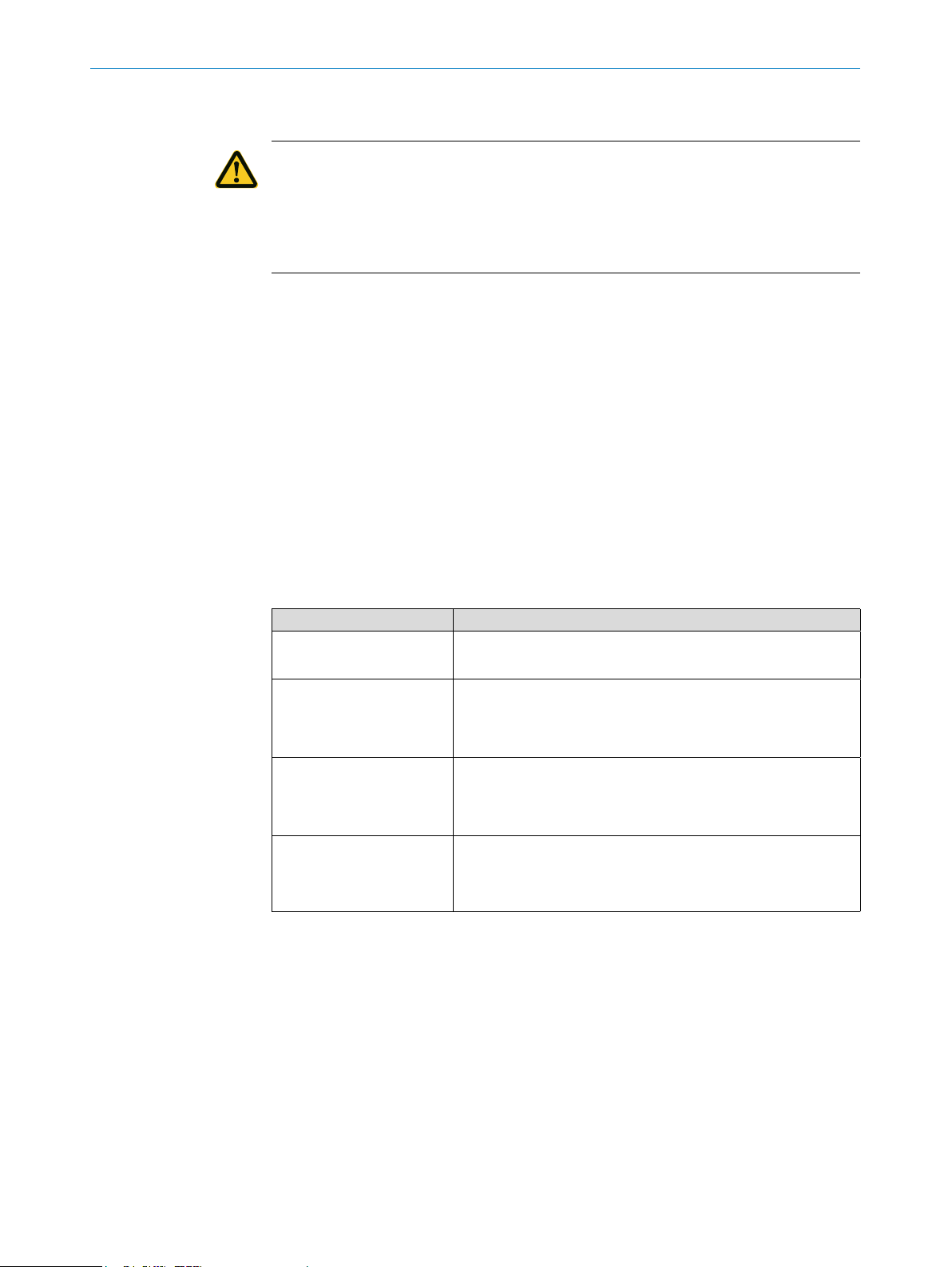
The following qualications are required for various activities:
Activities Qualication
Mounting, maintenance
Electrical installation, de-
vice replacement
Commissioning,
conguration
Operation of the device for
the specic application
• Basic practical technical training
• Knowledge of the current safety regulations in the workplace
• Practical electrical training
• Knowledge of current electrical safety regulations
• Knowledge of device control and operation in the specic application concerned (e.g., conveying line)
• Basic knowledge of the control system used
• Basic knowledge of the design and setup of the described
connections and interfaces
• Basic knowledge of data transmission
• Knowledge of device control and operation in the specic application concerned (e.g., CIP/SIP system)
• Knowledge of the software and hardware environment for the
specic application concerned (e.g., CIP/SIP system)
2.6 Operational safety and specic hazards
Please observe the safety notes and the warnings listed here and in other chapters of
these operating instructions to reduce the possibility of risks to health and avoid dan-
gerous situations.
Subject to change without notice
OPERATING INSTRUCTIONS | DOSIC® 8020955/11HD / 2018-12-12| SICK AG
9
Page 10

2 SAFETY INFORMATION
2.7 Use at high operating temperatures
When the process temperature is high, the sensor housing may get hot.
CAUTION
Risk of burning on sensor housing
• Only touch the hot housing if you are wearing safety gloves.
2.8 General safety notes
• Read the operating instructions prior to commissioning.
• These operating instructions are valid for devices from rmware version 2.00.
®
• The DOSIC
• Observe national safety and work safety regulations.
• Wiring work and the opening and closing of electrical connections may only be
carried out when the power is switched o.
• The radiated power is far lower than that from telecommunication equipment.
According to current scientic research, the operation of this device can be classied as safe and non-hazardous.
is not a safety component under the EU Machinery Directive.
2.9 Repairs
Repair work on the sensor may only be performed by qualied and authorized personnel from SICK AG. Interference with or modications to the sensor on the part of the
customer will invalidate any warranty claims against SICK AG.
The customer is only permitted to change the alignment of the display and to remove
the display cover in order to change its position.
10
OPERATING INSTRUCTIONS | DOSIC® 8020955 /11HD/ 2018-12-12 | SICK AG
Subject to change without notice
Page 11

3 Product description
3.1 Product identication
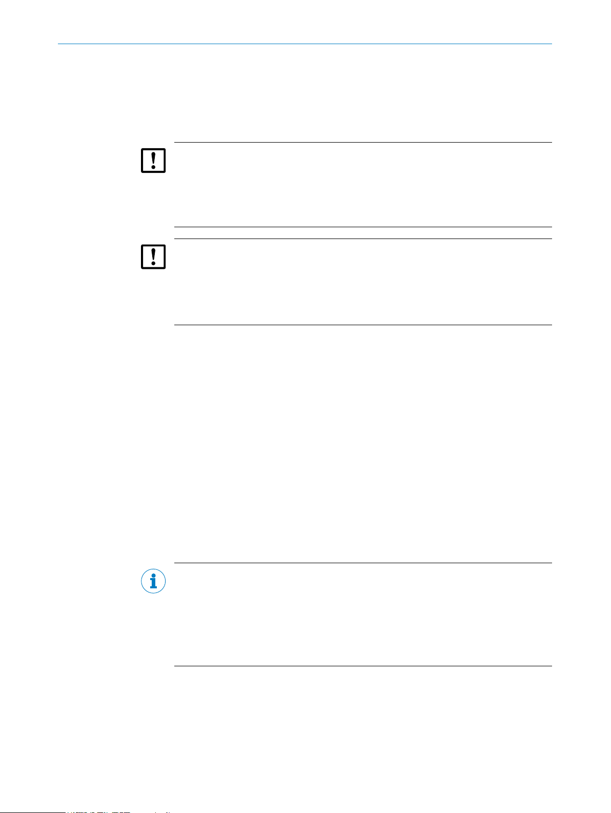
3.1.1 Information on the housing
Information for identication of the sensor and its electrical connection are marked on
the housing.
The serial number, the part number and the type code are printed on a label stuck on
the side of the display. It is visible after removing of the top cover of the sensor.
3.1.2 Type code
DOSIC® FUM - H 015 F 1 GC 5
1 2 3 4 5 6 7
Position Description
1 Product group
2 Variant
3 Channel size
4 Medium
5 Display
6 Process connection
7 Electrical connections
®
DOSIC
(ow sensors)
H: Hygienic
015: DN15
025: DN25
F: Liquids
1: Yes
GC: G 3/4 (DN15 only)
GE: G 1 1/4 (DN25 only)
CB: Clamp DN15 DIN 32676 (external diameter 34 mm)
CD: Clamp DN25 DIN 32676 (external diameter 50.5 mm)
MB: DIN 11851 DN15 (thread on both ends)
MD: DIN 11851 DN25 (thread on both ends)
NC: NPT 3/4 (DN15 only)
NE: NPT 1 1/4 (DN25 only)
5: M12, 5-pin (2 DI/O; 1 AO)
8: M12, 8-pin (2 DI/O; 2 AO)
3PRODUCT DESCRIPTION
Subject to change without notice
Not all variants of the type code can be combined!
OPERATING INSTRUCTIONS | DOSIC® 8020955/11HD / 2018-12-12| SICK AG
11
Page 12
3 PRODUCT DESCRIPTION
3.2 Product characteristics
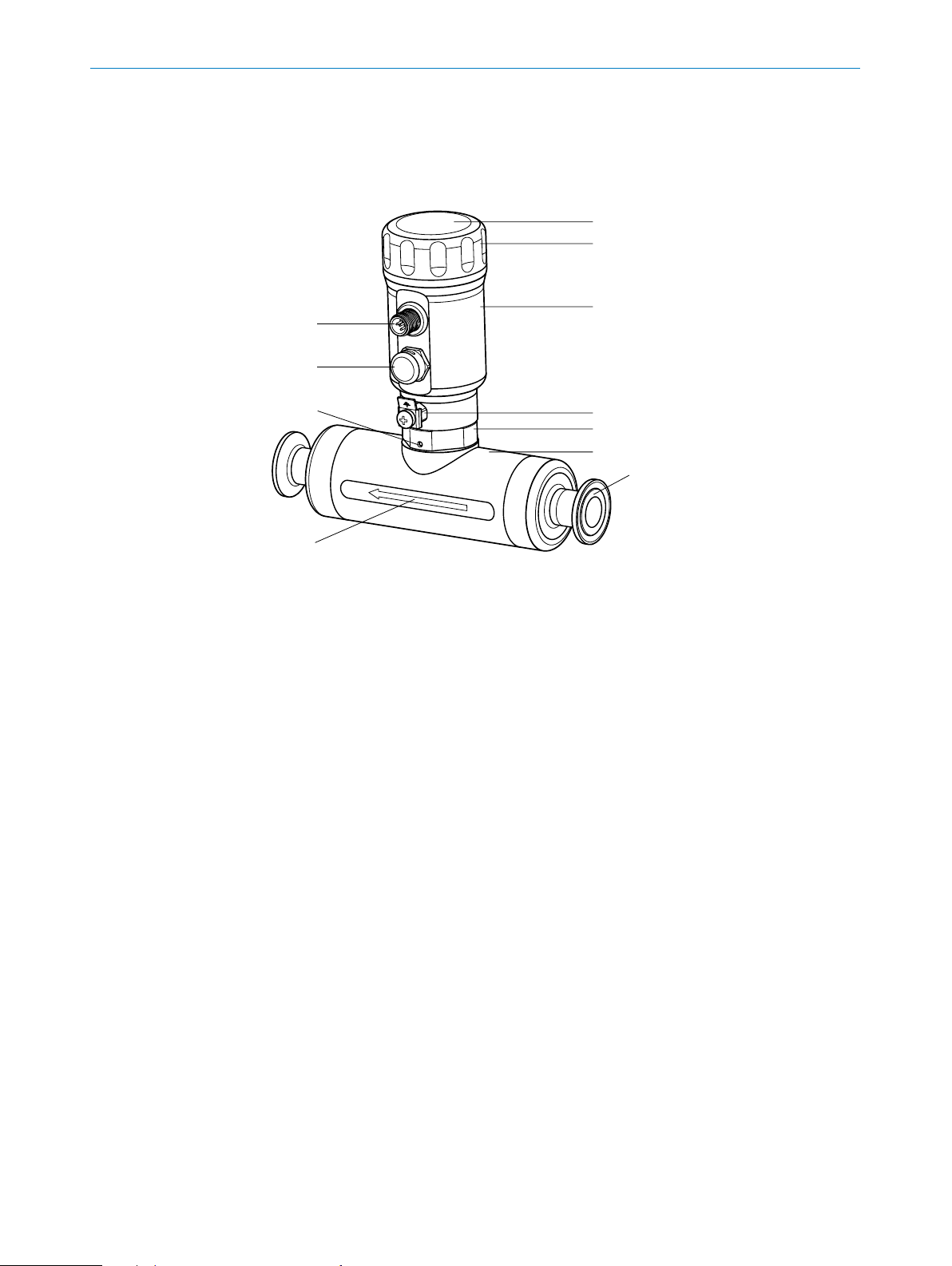
3.2.1 Device view
4
5
1
2
3
8
6
7
9
ß
à
Fig. 1: DOSIC® overview
1 Display and operating buttons
2 Upper cover
3 Upper housing
4 M12 electrical connection
5 Pressure compensation element (prevents build-up of condensate)
6 Connection for ground cable
7 Nut to unlock/lock housing rotation
8 Screw to unlock/lock screw nut 7
9 Measuring channel
ß Process connection
à Flow direction
3.2.2 Operating buttons
The sensor is operated using the display and the operating buttons.
For a detailed description of the buttons and their functions, see “7.2.1 Display and
operating buttons”.
12
OPERATING INSTRUCTIONS | DOSIC® 8020955 /11HD/ 2018-12-12 | SICK AG
Subject to change without notice
Page 13

3.3 Product features and functions
3.3.1 Principle of operation
®
The DOSIC
method, making the sensor suitable for measuring both conductive and non-conductive
liquids.
The sensor has two congurable digital inputs and outputs and up to two analog outputs. The switching output (Q1) also features an IO-Link interface; see “7.2.3 IO-Link”.
3.3.2 Fields of application
With its measurement channel and stainless-steel housing, the ultrasonic owmeter is
suitable for measuring tasks in hygienic environments. The compact and rugged design
makes the sensor ideal for a wide range of applications, including those where space
restrictions or aggressive media play a role.
Installation is quick and easy, and does not require medium calibration. The seal-free,
self-draining measuring channel enhances process reliability. The straight shape of the
measuring channel reduces pressure loss, which in turn reduces energy costs.
The DOSIC
are FDA-compliant.
This makes the DOSIC
measures ow volume using ultrasonic technology and the time-of-ight
®
is EHEDG-certied, and all materials that come into contact with the media
®
suitable for use in applications such as:
3PRODUCT DESCRIPTION
− The food industry
− CIP/SIP systems
− Filter systems
− Osmosis systems
− Measurements with high-purity water
NOTE
Due the ultrasonic technology used is always recommended to perform evaluation tests
on media that dier from water. To perform a rst evaluation test it is enough to ll the
channel of the sensor and close the two process connections of the sensor with blind
plugs. Should the sensor show zero ow without any error message there is a good
probability that the medium can be measured. In any case a test in the nal installation conditions provides the denitive answer if the DOSIC
®
can measure the specic
medium.
Subject to change without notice
OPERATING INSTRUCTIONS | DOSIC® 8020955/11HD / 2018-12-12| SICK AG
13
Page 14

4 TRANSPORT AND STORAGE
4 Transport and storage
4.1 Transport
For your own safety, please read and observe the following notes:
IMPORTANT
Damage to the sensor due to improper transport.
• The device must be packaged for transport with protection against shock and damp.
• Recommendation: Use the original packaging as it provides the best protection.
• Transport should be performed by specialist sta only.
• The utmost care and attention is required at all times during unloading and transportation on company premises.
• Note the symbols on the packaging.
• Do not remove packaging until immediately before starting installation work.
4.2 Transport inspection
Immediately upon receipt in Goods-in, check the delivery for completeness and for any
damage that may have occurred in transit. In the case of transit damage that is visible
externally, proceed as follows:
4.3 Storage
• Do not accept the delivery or only do so conditionally.
• Note the scope of damage on the transport documents or on the transport compa-
ny's delivery note.
• File a complaint.
NOTE
Complaints regarding defects should be led as soon as these are detected. Damage
claims are only valid before the applicable complaint deadlines.
Store the device under the following conditions:
• Recommendation: Use the original packaging.
• Do not store outdoors.
• Store in a dry area that is protected from dust.
• Do not store in an airtight container: this is so that any residual moisture present
can escape.
• Do not expose to any aggressive substances.
• Protect from sunlight.
• Avoid mechanical shocks.
14
• Storage temperature: see “13 Technical data”.
• For storage periods of longer than 3 months, check the general condition of all
components and packaging on a regular basis.
OPERATING INSTRUCTIONS | DOSIC® 8020955 /11HD/ 2018-12-12 | SICK AG
Subject to change without notice
Page 15

5 Mounting
5.1 Installation conditions
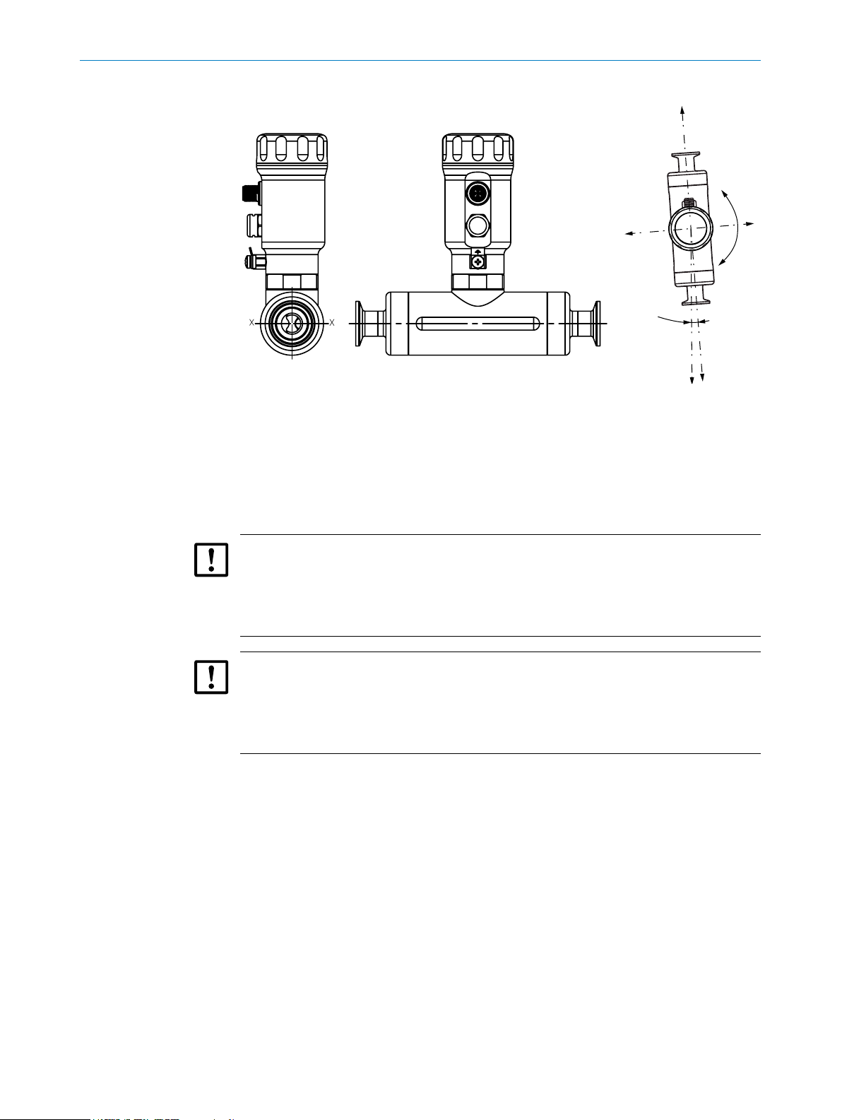
Install the sensor in line with the ow direction of the measurement medium (refer to
the arrow on the measurement channel). The measurement medium must ll the mea-
surement channel completely.
The formation of gas in the measurement medium can aect the measurement. For
this reason, the sensor should be installed in a section where no gas formation is to be
expected (in a vertical position where possible 1).
Where pumps are used, we recommend installing the sensor after the pump (pressure
side). Solid particles will aect the measurement. Ensure that no solid particles can
aect the measurement (e.g., by using lters).
The installation of inlet and outlet zones in the system is recommended. The inlet zone
is a straight section of pipe of 5 x DN length 2. The outlet zone is a section of 3 x DN
length3. Increase the inlet zone to 15 x DN when the sensor is installed after a pump.
Increase the inlet zone to 15 x DN when the sensor is installed after a valve. The tubes
must not cause turbulences.
To ensure that the measurement channel is kept full with the medium to be measured
at all times, the sensor should not be mounted in front of or in down pipes, or at the
highest point in the system 4.
5MOUNTING
The sensor head can be turned to facilitate optimum installation. To turn the sensor
head, the nut and the locking screw on the base of the sensor head must be loosened,
and then tightened again once the sensor head has been turned (nut: 30 Nm ... 40 Nm;
locking screw: 0.7 Nm ... 0.9 Nm).
The X-axis of the measurement channel should be installed at a horizontal angle to the
ground 5. Where the sensor is being installed vertically and in an EHEDG-compliant
installation, we recommend that the oset angle between inlet and outlet zone and
Y-axis not exceed 4°, in order to allow self-drainage to take place 6.
For EHEDG-compliant installation, EHEDG-certied seals must be used (not supplied).
4
1
3
2
Subject to change without notice
Fig. 2: Recommended installation
OPERATING INSTRUCTIONS | DOSIC® 8020955/11HD / 2018-12-12| SICK AG
15
Page 16
5 MOUNTING
5
6
+ Y
X
-Y
g
Fig. 3:
X
4°
DOSIC installation conditions
1Installation in section without gas formation
2Inlet zone of 5 x DN length
3Outlet zone of 3 x DN length
4Not installed in front of or in down pipes or at the highest point
5X-axis of measurement channel installed at a horizontal angle to the ground
6Oset between inlet and outlet zone and Y-axis not exceeded 4°
IMPORTANT
The display cover at the top end of the housing must be screwed into position manually,
by turning it until it no longer moves (see “3.2.1 Device view” on page 12., item num-
ber 2). The M12 connection must also be properly secured to ensure that the IP67/
IP69 enclosure rating is achieved.
IMPORTANT
The tightening torque on the process connection threads must not exceed 35 Nm
(DN15) and 80 Nm (DN25). Do not push or pull the upper housing while the process
connections are being tightened or while other work is being carried out. The force ap-
plied to the upper housing must not exceed 280 N (DN15) and 350 N (DN25).
16
OPERATING INSTRUCTIONS | DOSIC® 8020955 /11HD/ 2018-12-12 | SICK AG
Subject to change without notice
Page 17
6 Electrical installation
6.1 Safety
6.1.1 Notes on the electrical installation
IMPORTANT
Equipment damage due to incorrect supply voltage!
An incorrect supply voltage may result in damage to the equipment.
• Only operate the device using a protected low voltage and safe electrical insulation
as per protection class III.
IMPORTANT
Equipment damage or unpredictable operation due to working with live parts.
Working with live parts may result in unpredictable operation.
• Only carry out wiring work when the power is o.
• Only connect and disconnect electrical connections when the power is o.
6ELECTRICAL INSTALLATION
• The electrical installation must only be performed by electrically qualied person-
nel.
• Standard safety requirements must be met when working on electrical systems.
• Only switch on the supply voltage for the device when the connection tasks have
been completed and the wiring has been thoroughly checked.
• When using extension cables with open ends, ensure that bare wire ends do not
come into contact with each other (risk of short-circuit when supply voltage is
switched on!). Wires must be appropriately insulated from each other.
• Wire cross-sections in the supply cable from the user's power system must be
designed in accordance with the applicable standards. In Germany, observe the
following standards:
DIN VDE 0100 (Part 430) and DIN VDE 0298 (Part 4) or DIN VDE 0891 (Part 1).
• Circuits connected to the device must be designed as SELV circuits (SELV = Safety
Extra Low Voltage).
• Protect the device with a separate fuse at the start of the supply circuit.
Notes on layout of data cables:
• Use screened data cables with twisted-pair wires.
• Implement the screening design correctly and completely.
• To avoid interference, e.g., from switching power supplies, motors, clocked drives,
and contactors, always use suitable EMC cables and layouts.
• Do not lay cables over long distances in parallel with voltage supply cables and motor cables in cable channels.
Subject to change without notice
The IP67 and/or IP69 enclosure rating for the device is only achieved under the following conditions:
• The cable on the M12 connection has been screwed on.
• The top cover is screwed (no gap between the upper cover and upper housing).
OPERATING INSTRUCTIONS | DOSIC® 8020955/11HD / 2018-12-12| SICK AG
17
Page 18
6 ELECTRICAL INSTALLATION
If this is not done, the device does not fulll any specied IP enclosure rating!
6.2 Electrical connection
6.2.1 Overview of the electrical connections
The sensor is connected using a pre-assembled female cable connector with M12 x
1 plug connector (5-pin or 8-pin). With the power switched o, plug the female cable
connector into the sensor and screw it tight.
Connect the cable according to its function. After the supply voltage has been applied,
the sensor carries out a self-test. Once installed, the sensor is ready for operation on
completion of the self-test. The display shows the current measured value.
Fig. 4: DOSIC® M12 male connector
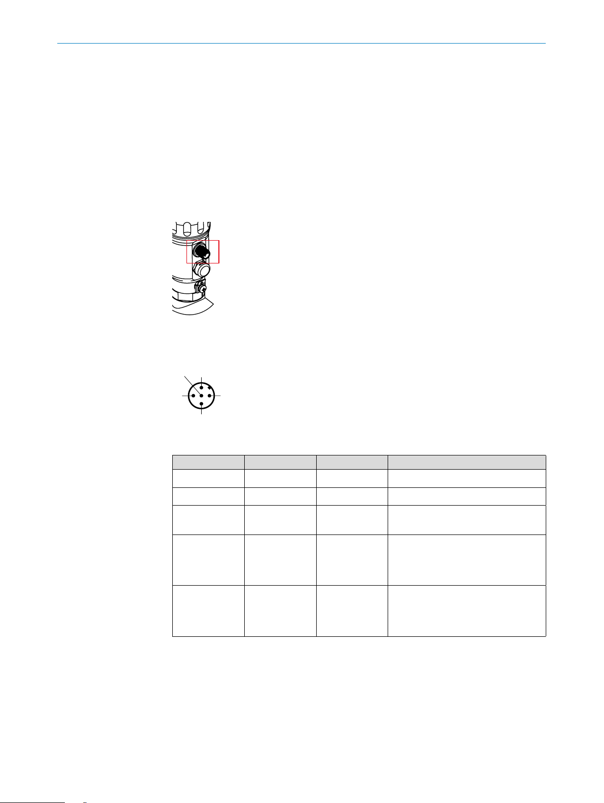
6.2.2 Pin assignment, M12 plug connector, 5-pin
Fig. 5: M12 x 1 plug connector, 5-pin
Contact Identication Wire color Description
1 L+ Brown Supply voltage
2 Q
3 M Blue Ground, reference potential for current
4 C/ Q
5 Q
A
1
2
White Analog current output 4 mA ... 20 mA
output
Black Digital input or digital output (PNP/
NPN/push-pull/open collector). IO-Link
communication (available only if Q1 is
dened as PNP or push-pull).
Gray Digital input or digital output (PNP/
NPN/push-pull/open collector). Switching/frequency/pulse output available
only if Q2 is dened as a digital output.
18
The table above shows only the standard pin assignment. Other pin assignments are
possible.
OPERATING INSTRUCTIONS | DOSIC® 8020955 /11HD/ 2018-12-12 | SICK AG
Subject to change without notice
Page 19

6.2.3 Pin assignment, M12 plug connector, 8-pin
6ELECTRICAL INSTALLATION
Fig. 6: M12 x 1 plug connector, 8-pin
Contact Identication Description
1 L+ Supply voltage
2 Q
2
3 M Ground, reference potential for current output
4 C/Q
1
5 No function
6 No function
7 Q
8 Q
A
B
The table above shows only the standard pin assignment. Other pin assignments are
possible.
Digital input or digital output (PNP/NPN/push-pull/open
collector). Switching/frequency/pulse output available
only if Q2 is dened as a digital output.
Digital input or digital output (PNP/NPN/push-pull/open
collector). IO-Link communication available only if Q
dened as PNP or push-pull.
is
1
Analog current output 4 mA ... 20 mA
Analog current output 4 mA ... 20 mA
The wire colors for 8-pin cables are not uniform. Always note the pin assignment of the
sensor.
Subject to change without notice
OPERATING INSTRUCTIONS | DOSIC® 8020955/11HD / 2018-12-12| SICK AG
19
Page 20

7 COMMISSIONING
7 Commissioning
7.1 Quick commissioning (with factory settings)
Quick commissioning is used in applications under reference conditions see “5.1 Instal-
lation conditions”.
Commissioning
1. Install the sensor in line with the installation conditions in “5 Mounting” During the
2. Switch on the supply voltage.
In the event of problems during commissioning, see “10 Troubleshooting”.
®
DOSIC
The sensor performs a self-test and is then ready for operation. The display shows
the current measured value.
installation process, the pipe system must be empty.
7.2 Operation
7.2.1 Display and operating buttons
The display automatically alternates between various states, which can be pre-congured using the menu.
You can access the menu by pressing the Set pushbutton for at least 2 seconds.
Set display A and display B
1. Make your selection in the Cong menu and conrm using Set.
2. Select Disp A or Disp B and conrm using Set.
3. Select the display value and conrm using Set.
7.2.2 Display and operating elements
7.2.3 IO-Link
20
OPERATING INSTRUCTIONS | DOSIC® 8020955 /11HD/ 2018-12-12 | SICK AG
57.00
Arrow pushbuttons: For navigating in the menu and changing values
Set pushbutton: For saving and conrming values and selecting the sub-menu
Esc pushbutton: For exiting the operating menu one step at a time
For operation via IO-Link, an IODD le, function blocks of common PLCs and a descrip-
tion of the available telegram parameters can be downloaded from www.sick.com.
IO-Link is available only if Q1 is dened as output and under Q1Type is dened as PNP
or Push-Pull.
L/min
Subject to change without notice
Page 21

7.3 Conguration of digital switching inputs and switching outputs
7.3.1 Selection of digital switching inputs and switching outputs
For Q1Mode (Q2Mode), you can choose either digital switching input or digital switching
output. If Q1 (Q2) has been set as an input, the switching behavior for this input is
dened in Q1Act (Q2Act). ResetV and CutO are available as options.
If Q1Mode (Q2Mode) is set as output, you can choose the behavior between ow,
temperature, and state (under Q1Proc or Q2Proc). If Q1Proc (Q2Proc) is set as a State,
Q1Stat (Q2Stat) can be selected as a Fail, Empty, Steril or Negatv.
If Q1Mode (Q2Mode) has been set as an output, you can choose hysteresis or window
function as switching output behavior. You can only choose between switch, frequency
and pulse if Q2Mode has been set as an output.
If Q1Mode (Q2Mode) has been set as an output, you can choose between the electrical
mode PNP, NPN, Push-Pull and open collector. The output type can be set to normally
open or normally closed with the parameter Q1Pol (Q2Pol).
Simulated values can be generated for Q1 and Q2 when chosen as output. The sim-
ulation mode can be set under QxSim. The available values are SimO, Active, and
Inactive. The values for active and inactive depend on the settings congured under
QxType and QxPol.
7COMMISSIONING
Note:
The following conguration options apply to both Q1 and Q2. They apply to Q2 only
when Q2Func is set to switch.
7.3.2 Conguration of the switching output
If the ow (or temperature) is uctuating around the set value, the hysteresis keeps the
switching status of the outputs stable.
When the ow (or temperature) is increasing, the output switches when the respective
switching point (SP) is reached; if the ow (or temperature) sinks again, the output
switches back only after the reset switching point (RP) has been reached.
The window function enables monitoring of a dened range. If the ow (or temperature)
is between window high (FH) and window low (FL), the output will be active (normally
open) and/or inactive (normally closed).
The error status of the measuring device reects the cable break monitoring. During an
error status, the measuring device switches to the safe state; i.e., the switching outputs
become inactive.
As far as the downstream signal evaluation is concerned, this corresponds to a cable
break.
7.3.3 Normally open with congurable hysteresis
Conguration (based on Q1 as an example)
Subject to change without notice
1. Congure the Q1 switching output as normally open.
• Select no in the Q1Pol menu and conrm using Set.
2. Congure hysteresis.
• Select Hyst in the Q1Out menu and conrm using Set.
3. Set the switching point.
OPERATING INSTRUCTIONS | DOSIC® 8020955/11HD / 2018-12-12| SICK AG
21
Page 22

7 COMMISSIONING
Switching output behavior
• Set the value for Flow or Temperature in the Q1SP menu and conrm using
Set.
4. Set the reset point.
• Set the value for Flow or Temperature in the Q1RP menu and conrm using
Set.
5. Select the electrical property (NPN/PNP/DRV/OC).
Select the parameter in the Q1Type menu and conrm using Set.
The following rules apply:
• Q1-PNP = Switching output in PNP circuit
• Q1-NPN = Switching output in NPN circuit
• Q1-DRV = Switching output in Push-Pull function
• Q1-OC = Switching output in open collector function
Flow/temperature
SP
RP
active
deactivated
Switching
Error signal
PNP NPN DRV OC Error status
output
Normally open/
HNO
Active High Low High (PNP switched) Low
Inactive Low High Low (NPN switched) High
7.3.4 Normally closed with congurable hysteresis
Conguration (based on Q1 as an example)
1. Congure the Q1 switching output as normally closed.
• Set the parameter in the Q1Pol menu to nc and conrm using Set.
2. Congure hysteresis.
t
Inactive
22
• Set the parameter in the Q1Out menu to Hyst and conrm using Set.
3. Set the switching point.
• Set the value for Flow or Temperature in the Q1SP menu and conrm using
Set.
4. Set the reset point.
• Set the value for Flow or Temperature in the Q1RP menu and conrm using
Set.
5. Select the electrical property (NPN/PNP/DRV/OC).
OPERATING INSTRUCTIONS | DOSIC® 8020955 /11HD/ 2018-12-12 | SICK AG
Subject to change without notice
Page 23

Select the parameter in the Q1Type menu and conrm using Set.
The following rules apply:
• NPN = Switching output in NPN circuit
• PNP = Switching output in PNP circuit
• DRV = Switching output in Push-Pull function
• OC = Switching output in open collector function
Switching output behavior
Flow/temperature
SP
RP
7COMMISSIONING
t
active
deactivated
Switching
output
Normally
closed/HNC
Active High Low High (PNP switched) Low
Inactive Low High Low (NPN switched) High
7.3.5 Normally open with window function
Conguration (based on Q1 as an example)
1. Congure the Q1 switching output as normally open.
• Set the parameter in the Q1Pol menu to no and conrm using Set.
2. Congure window mode.
• Set the parameter in the Q1Out menu to Window and conrm using Set.
3. Set the switching point.
• Set the value for Flow or Temperature in the Q1FH menu and conrm using
Set.
Error signal
PNP NPN DRV OC Error status
Inactive
Subject to change without notice
4. Set the reset point.
• Set the value for Flow or Temperature in the Q1FL menu and conrm using
Set.
5. Select the electrical property (NPN/PNP/DRV/OC).
Select the parameter in the Q1Type menu and conrm using Set.
The following rules apply:
• NPN = Switching output in NPN circuit
• PNP = Switching output in PNP circuit
• DRV = Switching output in Push-Pull function
OPERATING INSTRUCTIONS | DOSIC® 8020955/11HD / 2018-12-12| SICK AG
23
Page 24

7 COMMISSIONING
Switching output behavior
• OC = Switching output in open collector function
Flow/temperature
FH
FL
t
active
deactivated
Switching
output
Active High Low High (PNP switched) Low
Normally open/
FNO
Inactive Low High Low (NPN switched) High
7.3.6 Normally closed with window function
Conguration (based on Q1 as an example)
1. Congure the Q1 switching output as normally closed.
• Set the parameter in the Q1Pol menu to nc and conrm using Set.
2. Congure window mode.
• Set the parameter in the Q1Out menu to Window and conrm using Set.
3. Set the switching point.
Error signal
PNP NPN DRV OC Error status
Inactive
• Set the value for Flow or Temperature in the Q1FH menu and conrm using
Set.
4. Set the reset point.
• Set the value for Flow or Temperature in the Q1FL menu and conrm using
Set.
5. Select the electrical property (NPN/PNP/DRV/OC).
Select the parameter in the Q1Type menu and conrm using Set.
The following rules apply:
• NPN = Switching output in NPN circuit
• PNP = Switching output in PNP circuit
• DRV = Switching output in Push-Pull function
• OC = Switching output in open collector function
24
OPERATING INSTRUCTIONS | DOSIC® 8020955 /11HD/ 2018-12-12 | SICK AG
Subject to change without notice
Page 25

Switching output behavior
Flow/temperature
FH
FL
active
deactivated
7COMMISSIONING
t
Error signal
7.3.7 Pulse output
Switching
output
Normally
closed/FNC
Active High Low High (PNP switched) Low
Inactive Low High Low (NPN switched) High
PNP NPN DRV OC Error status
Inactive
If pulse has been selected as output for Q2, PlsVal can be used to dene the pulse
value (denition of the volume that generates a pulse). PlsWid can be used to dene
the pulse width (duration of a pulse in μs).
Example:
PulsVal = 1000 ml, PulsWid = 50 μs
A pulse will be generated when 1000 ml are counted and the pulse duration will be 50
μs.
It is important to ensure that the pulse width set is as short as possible and as long as
necessary so that the device connected to the digital output still recognizes the pulse
(to avoid overlapped pulses). If the set pulse value is reached, a pulse is sent out at the
digital output.
If the pulse valency chosen by the user is too low, the pulse repetition rate can get too
high, leading to the sensor outputting a lower number of pulses than it should. If this is
the case, the sensor will show the warning [i]HiFrq on the display (and “Q2 frequency
too high” over the active notications of IO-Link).
Example:
Conguration: PlsVal = 100 μL
Measured owrate = 60 L/min --> Pulse repetition rate clipped to 100 ns -->
Warning [i]HiFrq
7.3.8 Frequency output
If frequency has been selected as the output for Q2, FrqMax and FrqMin can be used to
dene the maximum and minimum frequencies.
The maximum frequency corresponds to the fullscale value. The minimum frequency
corresponds to the intial scale value.
The fullscale value and the initial scale value are dened by Q2SP and Q2RP respectively.
Subject to change without notice
OPERATING INSTRUCTIONS | DOSIC® 8020955/11HD / 2018-12-12| SICK AG
25
Page 26

7 COMMISSIONING
Q2SP can be used to dene the maximum ow, and Q2RP can be used to dene the
minimum ow.
Example:
FrqMax = 10.000 (Hz)
FrqMin = 0 (Hz)
Q2SP = 36.00 (L/min)
Q2RP = 0 (L/min)
With these settings, the output frequency varies between 0 and 10.000 Hz when the
ow is changed from 0 to 36 L/min. If the ow is 18 L/min, for example, the output
frequency is 5.000 Hz.
The frequency output can be simulated under Q2Sim.
Depending on the parameterization of the frequency output, the output frequency can
be higher than 10 kHz or lower than 0 Hz. In case the frequency is too high, the sensor
will show the warning [i]HiFrq on the display (and “Q2 frequency too high” over the
active notications of IO-Link).
In case the frequency is too low, the sensor will show the warning [i]LoFrq on the display
(and “Q2 frequency too low” over the active notications of IO-Link).
Example:
Conguration: FrqMax = 10kHz, FrqMin = 0Hz, Q2SP = 10.0L/min, Q2RP = 0.0L/min
Measured owrate = 20 L/min --> Output frequency clipped to 10 kHz à Warning [i]
HiFrq
Measured owrate = -20 L/min --> Output frequency clipped to 0 kHz à Warning [i]LoFrq
7.4 Conguration of analog outputs
Conguration
1. Select the QaType or QbType (only 8-pin variant) menu using the arrow pushbut-
tons and conrm using Set.
The available values are O or 4-20 mA.
7.4.1 Current output 4-20 mA
The analog current outputs Qa and Qb can be congured as ow or/and temperature.
However, Qb can only be congured in the 8-pin variant.
Conguration (based on Qa as an example)
1. Set the parameter in the QaType menu to 4-20 mA.
2. Select ow or temperature (under QaProc).
26
3. Set the upper limit value (20 mA or 4 mA, depending on the setting under QaPol).
• In the QaHigh menu, set the value for ow range (e.g., 100.0) or temperature
(e.g., 60 °C).
4. Set the lower limit value (4 mA or 20 mA, depending on the setting under QaPol).
• In the QaLow menu, set the value for ow range (e.g., 50.0) or temperature
(e.g., 40 °C).
5. Invert the signal.
The analog signal can be inverted in the QaPol menu.
Set the parameter to “Inverted” in the QaPol menu.
OPERATING INSTRUCTIONS | DOSIC® 8020955 /11HD/ 2018-12-12 | SICK AG
Subject to change without notice
Page 27

• Normal = Analog output signal as congured
• Inverted = Analog output signal is inverted; the value congured for QaHigh
6. Set QaFail to 3.5 mA or 21.5 mA.
In the event of an error, a corresponding signal is output.
7.5 Advanced functions
7.5.1 Measurement Mode
Two dierent application specic measurement modes are available:
• Standard: standard measurement mode with high measurement accuracy for
• Dynamic: fast measurement mode suitable for dynamic applications (e.g.
Conguration
1. Set the parameter Mode in the Meas menu.
The available values are: Stndrd, Dynamc
7COMMISSIONING
corresponds to 4 mA and the value congured for QaLow corresponds to 20
mA
steady/slow changes processes.
pulsating ow pumps).
NOTE
When using the Dynamc measurement mode, it is recommended to increase the sen-
sitivity of the sensor in order to react to changes in the owrate as quickly as possible.
This may be done by using the following settings in the CutO menu (see 7.5.3 Zero
ow cuto):
Set = 0.15 L/min
Reset = 0.05 L/min .
7.5.2 Activate ltering
Smoothing of the measured value, e.g., if ow is irregular (e.g. when pumps are starting
and stopping). For fast changes, the average of the measured values over a predened
number of seconds is output.
Conguration
1. Set the parameter in the Filter menu.
7.5.3 Zero ow cuto
As the DOSIC
smallest movements in the medium. If the ow rate of a medium is zero, this can result
in inaccurate measurements.
The available values are: O, 500 ms, 1 s, 2 s, 5 s, 10 s.
®
is a highly sensitive piece of equipment, the sensor detects even the
Subject to change without notice
The leak ow volume suppression feature helps prevent these measurements from
triggering unwanted switching behavior or causing incorrect meter readings. With this
feature, the sensor treats very low values as zero ow readings. If the ow drops below
a dened reset value, the display and output are reset to zero. When the ow rises
above the dened set value once more, the measurements continue.
OPERATING INSTRUCTIONS | DOSIC® 8020955/11HD / 2018-12-12| SICK AG
27
Page 28

7 COMMISSIONING
Conguration
NOTE
The analog output outputs the current which has been set for Q = 0 L/min.
The frequency output outputs the frequency set for Q = 0 L/min.
The pulse output does not output any pulses at Q = 0 L/min.
1. Select the Meas menu using the arrow pushbuttons and conrm using Set.
2. Select the Cuto menu using the arrow pushbuttons and conrm using Set.
3. Select the Mode menu using the arrow pushbuttons and conrm using Set.
The available values are Active and Inactive.
4. Select the value and conrm using Set.
5. Set the parameter in the Set menu.
• Select the value and conrm using Set.
6. Set the parameter in the Reset menu.
• Select the value and conrm using Set.
7.5.4 Empty measurement channel
You can pre-congure the required switching behavior that will take eect if the measurement channel is empty.
Conguration
1. Select the Meas menu using the arrow pushbuttons and conrm using Set.
2. Select the Empty menu using the arrow pushbuttons and conrm using Set.
The available values are 0-Flow and Fail.
3. Select the value and conrm using Set. For temperature the unit is shown as cho-
sen in the Units menu.
Parameter selection
Parameter Function
0-Flow The analog output is set to the relevant
Fail The error signal is output via Qx-Sta if
When the Q1Stat (Q2Stat) is selected as Fail or Empty the following situation and condition can be found on the output of the device:
value dened for QxLow.
QxStat is set as Fail.
28
State of channel Mapping of
QxStat
Filled with the
medium
Empty Empty ZeroFlow Ok High
Empty Empty Failure Fail Low (safe state)
OPERATING INSTRUCTIONS | DOSIC® 8020955 /11HD/ 2018-12-12 | SICK AG
Empty or Failure ZeroFlow or
Empty behavior System state Qx state
(normally open, as
long as no other
failure is present)
Ok Low
Failure
Subject to change without notice
Page 29

7COMMISSIONING
State of channel Mapping of
Empty Failure ZeroFlow Ok Low
Empty Failure Failure Fail High
7.5.5 Congure reverse ow direction
If the measurement medium ows through the sensor against the ow direction (see
arrow on sensor housing), the sensor can be congured to prevent negative measured
values.
Conguration
1. Select the Meas menu using the arrow pushbuttons and conrm using Set.
2. Select the Revrsl menu using the arrow pushbuttons and conrm using Set.
The available values are Active, Inactive and Abs.
3. Select the value and conrm using Set.
7.5.6 Simulate ow or temperature
Even if there is no liquid in the measurement channel yet, it is possible to select a ow
or temperature in the menu in order to test the sensor conguration.
When simulating a ow, all outputs on the DOSIC
guration. The function should not be selected until a conguration is complete.
QxStat
Empty behavior System state Qx state
®
are set according to the dened con-
(normally open, as
long as no other
failure is present)
Conguration
1. Select the Cong menu using the arrow pushbuttons and conrm using Set.
2. Select the SimFlw or SimTmp menu using the arrow pushbuttons and conrm
using Set.
3. Select the value and conrm using Set.
For temperature the unit is shown as chosen in the Units menu.
Parameter selection
SimFlw SimTmp
SimO: O SimO: O
-100 % ow 0 °C (32 °F)
-80 % ow 20 °C (68 °F)
-60 % ow 40 °C (104 °F)
-40 % ow 60 °C (140 °F)
-20 % ow 80 °C (176 °F)
0 % ow 100 °C (212 °F)
+20 % ow
+40 % ow
+60 % ow
+80 % ow
+100 % ow
Subject to change without notice
OPERATING INSTRUCTIONS | DOSIC® 8020955/11HD / 2018-12-12| SICK AG
29
Page 30

7 COMMISSIONING
NOTE
When the sensor is switched o and on again, the simulation mode is reset. The sensor
resumes live measurement.
7.5.7 Media compensation
This functions allows the sensor to be calibrated for a new medium via the 0-Flow menu
item or scaling the measured value with a dened factor via the Linear menu.
Conguring calibration for new medium
1. Select the Meas menu using the arrow pushbuttons and conrm using Set.
2. Select 0-Flow using the arrow pushbuttons and conrm using Set.
3. Select AutoCal using the arrow pushbuttons and conrm using Set.
The automatic calibration process is executed.
NOTE
• The measurement channel must be completely lled with medium.
• There must be no air in the measurement channel.
• The medium must not be owing while conguration takes place.
Conguring to compensate measurements
1. Select the Meas menu using the arrow pushbuttons and conrm using Set.
2. Select Linear using the arrow pushbuttons and conrm using Set.
3. Select LinFac using the arrow pushbuttons and conrm using Set.
Select the value and conrm using Set.
The measured value is multiplied by the relevant factor and output.
Default value is 1000 (corresponds to 100 %). Flow is represented 1:1.
Example:
LinFac = 1200 (corresponds to 120 %). Flow is increased by 20 %.
LinFac = 800 (corresponds to 80 %). Flow is reduced by 20 %.
7.5.8 Sterilization detection
The detection of a sterilization cycle is be performed by monitoring the process temperature. The following parameters are used under the menu Steril located under the
menu Meas:
Set (Sterilization temperature set point)
Reset (Sterilization temperature reset point)
Time (Sterilization time)
A sterilization cycle is detected, if the process temperature exceeds the sterilization
temperature set point and stays above the sterilization temperature reset point for at
least as long as the sterilization time.
30
Conguration
1. Select the Meas menu using the arrow pushbuttons and conrm using Set.
2. Select the Steril menu item using the arrow pushbuttons and conrm using Set.
OPERATING INSTRUCTIONS | DOSIC® 8020955 /11HD/ 2018-12-12 | SICK AG
Subject to change without notice
Page 31

3. Select Set using the arrow pushbuttons and conrm using Set.
4. Select the value and conrm using Set.
5. Select Reset using the arrow pushbuttons and conrm using Set.
6. Select the value and conrm using Set.
7. Select Time using the arrow pushbuttons and conrm using Set.
8. Select the value and conrm using Set.
A notication of the sterilization cycle can be output over a status output conguring
under the Q1Stat (Q2Stat) as Steril.
7.5.9 Evaluating signal quality
The signal quality is evaluated on the base of four dierent parameters: SigQu1,
SigQu2, SigQu3 and SigQu4.
These are described as follows.
SigQu1:
Indication for the robustness of the measurement environment. A low signal quality is
an indication for disturbances such as strong vibration on the measurement pipe or
turbulence formation due to a not correct installation conditions.
7COMMISSIONING
Value range: 0 to 100%
Good signal: > 50 %
SigQu2:
Indication for the attenuation of the ultrasound signal caused by the measured
medium. A low signal quality is an indication that some medium parameters could inuence the measurement (e.g. as viscosity or density too high).
Value range: 0 to 100%
Good signal: > 10 %
SigQu3:
Indication for the robustness of the ultrasound signals. A low signal quality is an indication for interferences on the signal path (e.g. gas bubbles or solid particles).
Value range: 0 to 100%
Good signal: > 30 %
SigQu4:
Not used. Available for future developments (always shown at 100 %).
7.5.10 Activating the display lock
To prevent the sensor from being tampered with, password protection can be activated
for the display.
Conguration
Subject to change without notice
When the protection is active, the expert password (036742) must be entered before
the menu can be accessed.
The menu is only unlocked once the correct password is entered.
1. Select the Cong menu using the arrow pushbuttons and conrm using Set.
2. Select the Lock menu item using the arrow pushbuttons and conrm using Set.
OPERATING INSTRUCTIONS | DOSIC® 8020955/11HD / 2018-12-12| SICK AG
31
Page 32

7 COMMISSIONING
3. The password protection is activated using Activate.
NOTE
• The user is logged out again after 5 minutes of inactivity.
• When the display is locked, only the congured measured value display can be seen.
7.5.11 Output options for Disp A and Disp B
Outside of the menu, the display alternates between dierent values, which can be
pre-congured via Disp A and Disp B.
• Flow (Flow)
• Fl+Unt (Flow and measuring unit)
• Volume (Volume)
• Temper (Temperature)
• QaCurr (Current value)
• QbCurr (Current value)
• QxStat (Status of the output)
• c (m/s) (Speed of sound)
• v (m/s) (Flow velocity)
7.5.12 Selecting display unit
This setting enables you to congure the units used for ow, volume, and temperature.
Conguration
1. Select the Cong menu using the arrow pushbuttons and conrm using Set.
2. Select the Units sub-menu using the arrow pushbuttons and conrm using Set.
Set values: Flow, Volume, Temper.
3. Select the value and conrm using Set.
Depending on the parameter, the following units are available:
Parameter Unit
Flow • L/min
Volume • L
Temper • °C
• L/h
3
/h
• m
• G/min
• Gal/h
3
• m
• Gal
• °F
32
OPERATING INSTRUCTIONS | DOSIC® 8020955 /11HD/ 2018-12-12 | SICK AG
Subject to change without notice
Page 33

7.5.13 Resetting to factory settings
Resetting all parameters to factory settings
1. Select the RstFac menu using the arrow pushbuttons and conrm using Set.
2. Press Set again.
7COMMISSIONING
Subject to change without notice
OPERATING INSTRUCTIONS | DOSIC® 8020955/11HD / 2018-12-12| SICK AG
33
Page 34

8 MENU OVERVIEW
2 s
8 Menu overview
RUN
RUN
RUN
RUN
RUN
RUN
Set Esc
DispA
DispB
[PRIO1]
[PRIO2]
[PRIO3]
Unit
L/min
L/h
m³/h
G/min
Gal/h
0.00
Esc
Set
Q1-##
MEN
Q1-Flw
MEN
Q1-Tmp
MEN
Q1-Sta
MEN
Q1-In
MEN
Set
Q1Mode
MEN
Esc
Q1Proc
MEN
Q1Act
MEN
Q1Out
MEN
Q1SP
MEN
Q1RP
MEN
Q1FH
MEN
Q1FL
MEN
Q1Stat
MEN
Set
Esc
Set
Esc
Set
Set
Esc
Set
Set
Set
Set
Set
SET
Output
SET
Input
SET
Flow
SET
Temper
SET
Status
SET
ResetV, CutOff
SET
Hyst
SET
Window
SET
###
SET
###
SET
###
SET
###
SET
Fail
SET
Empty
SET
Steril
Set
Set
Set
Always available
Conguration-dependent
Sub-menu-dependent
Variant-dependent
Failure
Set
Set
Set
Set
Set
Set
Set
Set
Set
Set
Set
Set
MEN
MEN
MEN
Q1Pol
Q1Sim
Q1Type
Set
Esc
Set
Esc
Set
Esc
SET
Negatv
SET
no, nc
SimOff,
SET
Inactv, Active
DRV, OC,
SET
NPN, PNP
Set
Set
Set
Set
Q1Proc is visible when Q1Mode is set as an Output.
Q1Act is visible when Q1Mode is set as an Input.
Q1Out is visible when Q1Mode is set as an Output and Q1Proc is set as Flow or Temper.
Q1SP and Q1RP are visible when Q1Out is set as Hyst.
Q1FH and Q1FL are visible when Q1Out is set as Window.
Q1Stat is visible when Q1Proc is set as Status.
34
OPERATING INSTRUCTIONS | DOSIC® 8020955 /11HD/ 2018-12-12 | SICK AG
Subject to change without notice
Page 35

MEN
Q1Pol
Q1Sim
Q1Type
Esc
Set
Esc
Set
Esc
Set
MEN
Q1RP
MEN
Q1FH
MEN
Q1FL
MEN
Set
Set
Set
###
SET
###
SET
###
SET
Q1Stat
MEN
Fail
SET
Empty
SET
Steril
SET
Set
Set
no, nc
SET
SimOff,
Inactv, Active
SET
DRV, OC,
NPN, PNP
SET
Set
Set
Set
Set
MEN
MEN
MEN
Negatv
SET
Set
Set
Set
Set
Set
MEN
MEN
MEN
MEN
Q2-##
Q2-Flw
Q2-Tmp
Q2-Sta
Q2-In
Set
Q2Mode
MEN
Esc
Q2Proc
MEN
Q2Func
MEN
Q2SP
MEN
Q2RP
MEN
Q2FH
MEN
8MENU OVERVIEW
Set
SET
Output
Esc
SET
Input
Set
SET
Flow
MEN
Esc
SET
Temper
SET
Status
Set
SET
Pulse
Esc
SET
Freq
SET
Switch
Set
SET
###
Set
SET
###
Set
SET
###
Set
Set
Set
Set
Set
Set
Set
Set
Set
Set
Set
Always available
Conguration-dependent
Sub-menu-dependent
Variant-dependent
Failure
MEN
MEN
MEN
MEN
MEN
MEN
MEN
MEN
MEN
MEN
MEN
Q2FL
PlsVal
PlsWid
FrqMax
FrqMin
Q2Act
Q2Out
Q2Stat
Q2Pol
Q2Sim
Q2Type
Set
SET
Set
Set
Set
Set
Set
Set
Esc
Set
Esc
Set
Esc
Set
Esc
Set
Esc
###
SET
###
SET
###
SET
###
SET
###
SET
ResetV, CutOff
SET
Hyst
SET
Window
SET
Fail
SET
Empty
SET
Steril
SET
Negatv
SET
no, nc
SimOff, Inactv,
SET
Active
DRV, OC,
SET
NPN, PNP
Set
Set
Set
Set
Set
Set
Set
Set
Set
Set
Set
Set
Set
Set
Set
Q2Proc is visible when Q2Mode is set as an Output.
Q2Act is visible when Q2Mode is set as an Input.
Q2Func is visible when Q2Mode is set as anOutput and Q2Proc is set as Flow.
Q2Out is visible when Q2Func is set as Switch and Q2Proc is set as Temper.
Q2SP and Q2RP are visible when Q2Out is set as Hyst and Q2Func as Freq.
Q2FH and Q2FL are visible when Q2Out is set as Window.
FrqMax and FrqMin are visible when Q2Func is set as Freq.
PlsVal and PlsWidare visible when Q2Func is set as Pulse.
Q2Stat is visible when Q2Proc is set as Status.
Subject to change without notice
OPERATING INSTRUCTIONS | DOSIC® 8020955/11HD / 2018-12-12| SICK AG
35
Page 36

8 MENU OVERVIEW
Q2-##
MEN
Q2-Flw
MEN
Q2-Tmp
MEN
Q2-Sta
MEN
Q2-In
MEN
Esc
Set
MEN
Q2Mode
MEN
Q2Proc
Esc
Set
Esc
Set
Output
SET
Input
SET
MEN
Q2Func
Esc
Set
Pulse
SET
Freq
SET
Switch
SET
Q2SP
Q2RP
Q2FH
Q2FL
MEN
MEN
MEN
MEN
MEN
Set
Set
Set
Set
###
SET
###
SET
###
SET
###
SET
PlsVal
MEN
Set
ResetV, CutOff
SET
MEN
MEN
MEN
Q2Pol
Q2Sim
Q2Type
Esc
Set
Esc
Set
Esc
Set
no, nc
SET
SimOff, Inactv,
Active
SET
DRV, OC,
NPN, PNP
SET
Q2Stat
MEN
Esc
Set
Fail
SET
Empty
SET
Steril
SET
Set
Set
Flow
SET
Temper
SET
Status
SET
Set
Set
Set
Set
Set
Set
Set
Set
Set
Set
Set
PlsWid
Esc
Set
Hyst
SET
Window
SET
Set
Set
MEN
FrqMax
Q2Act
Q2Out
FrqMin
Set
Set
Set
Set
###
SET
###
SET
###
SET
###
SET
Set
Set
Set
Set
Set
Set
Set
MEN
MEN
MEN
MEN
Set
Set
Set
Negatv
SET
Set
QaProc, QaPol, QaHigh, QaLow, QaFail and QaSim are visible when QaType is set as 4-20 mA.
Qa-##
MEN
Qa-Off
MEN
Qa-Flw
MEN
Qa-Tmp
MEN
Set
QaType
MEN
Esc
QaProc
MEN
QaPol
MEN
QaHigh
MEN
QaLow
MEN
QaFail
MEN
QaSim
MEN
Set
SET
Esc
SET
Set
SET
Esc
SET
Set
SET
SET
Set
Set
SET
Set
SET
Esc
Set
SET
Esc
Off
4 - 20mA
Flow
Temp
Normal, Invrtd
###
###
###
###
Set
Set
Set
Always available
Conguration-dependent
Sub-menu-dependent
Variant-dependent
Failure
Set
Set
Set
Set
Set
Set
36
OPERATING INSTRUCTIONS | DOSIC® 8020955 /11HD/ 2018-12-12 | SICK AG
Subject to change without notice
Page 37

Q2RP
Q2FH
Q2FL
MEN
MEN
MEN
Set
Set
Set
###
SET
###
SET
###
SET
PlsVal
MEN
Set
ResetV, CutOff
SET
MEN
MEN
MEN
Q2Pol
Q2Sim
Q2Type
Esc
Set
Esc
Set
Esc
Set
no, nc
SET
SimOff, Inactv,
Active
SET
DRV, OC,
NPN, PNP
SET
Q2Stat
MEN
Esc
Set
Fail
SET
Empty
SET
Steril
SET
QaProc
MEN
Esc
Set
Flow
SET
Temp
SET
QaHigh
MEN
QaLow
MEN
Set
Set
###
SET
###
SET
QaPol
MEN
Set
Normal, Invrtd
SET
QaFail
MEN
QaSim
MEN
Esc
Set
Esc
Set
###
SET
###
SET
Set
Set
Set
Set
PlsWid
Esc
Set
Hyst
SET
Window
SET
Set
Set
MEN
FrqMax
Q2Act
Q2Out
FrqMin
Set
Set
Set
Set
###
SET
###
SET
###
SET
###
SET
Set
Set
Set
Set
Set
Set
Set
MEN
MEN
MEN
MEN
Set
Set
Set
Qa-##
MEN
Qa-Off
MEN
Qa-Flw
MEN
Qa-Tmp
MEN
Esc
Set
MEN
QaType
Esc
Set
Off
4 - 20mA
SET
SET
Set
Set
Set
Set
Set
Set
Set
Set
Set
Negatv
SET
Set
8MENU OVERVIEW
Qb-##
MEN
Qb-Off
MEN
Qb-Flw
MEN
Qb-Tmp
MEN
QbProc, QbPol, QbHigh, QbLow, QbFail and QbSim are visible when QbType is set as 4-20 mA.
Set
QbType
MEN
Esc
QbProc
MEN
QbPol
MEN
QbHigh
MEN
QbLow
MEN
QbFail
MEN
QbSim
MEN
Set
SET
Esc
SET
Set
SET
Esc
SET
Set
SET
SET
Set
Set
SET
Set
SET
Esc
Set
SET
Esc
Off
4 - 20mA
Flow
Temp
Normal, Invrtd
###
###
###
###
Set
Set
Always available
Conguration-dependent
Sub-menu-dependent
Set
Variant-dependent
Failure
Set
Set
Set
Set
Set
Set
Subject to change without notice
OPERATING INSTRUCTIONS | DOSIC® 8020955/11HD / 2018-12-12| SICK AG
37
Page 38

8 MENU OVERVIEW
Always available
Conguration-dependent
Sub-menu-dependent
Variant-dependent
Failure
38
OPERATING INSTRUCTIONS | DOSIC® 8020955 /11HD/ 2018-12-12 | SICK AG
Subject to change without notice
Page 39

8MENU OVERVIEW
Config
MEN
Meas
MEN
Esc
Set
Esc
Set
MEN
Disp A
MEN
MEN
MEN
Units
SimFlw
SimTmp
MEN
Lock
MEN
Disp B
MEN
Filter
MEN
CutOff
MEN
Revrsl
MEN
Empty
MEN
Revrsl
MEN
Revrsl
MEN
Revrsl
MEN
Compns
Esc
Set
Esc
Set
Esc
Set
Esc
Set
Esc
Set
Esc
Set
Esc
Set
Esc
Set
Esc
Set
Esc
Set
Flow
Fl+Unt
Volume
Temper
QaCurr
QbCurr
QxStat
c (m/s)
v (m/s)
Flow
MEN
Volume
MEN
Temper
MEN
Mode
MEN
Set
MEN
Reset
MEN
Fail, 0-Flow
SET
Active, Inactv, Abs
SET
SimOff ###
SET
SimOff ###
SET
Off ###
SET
0-Flow
MEN
Linear
MEN
Esc
Set
Esc
Set
Esc
Set
Esc
Set
Esc
Set
Esc
Set
Esc
Set
Esc
Set
Set
Set
Set
Set
MEN
Steril
Esc
Set
Set
MEN
Reset
MEN
Time
MEN
Esc
Set
Esc
Set
Esc
Set
0...150°C
SET
0...150°C
SET
0...65535s
SET
Set
Set
Set
L/min, L/h, m³/h, gal/min, gal/h
SET
L, m³, gal
SET
Active, Inactv
SET
###
SET
###
SET
°C, °F
SET
MEN
Reset
MEN
AutCal
MEN
Reset
MEN
LinFac
Set
Set
Set
Set
Set
Set
Set
Set
Set
Set
Set
Set
Info
MEN
RstFac
MEN
Passwd
MEN
Set
MEN
Esc
MEN
MEN
MEN
MEN
MEN
MEN
MEN
Set
SET
Esc
Set
SET
Esc
SigQu1
SigQu2
SigQu3
SigQu4
FrmVer
SerNo
AppTag
DevTag
?#######
######
Set
SET
0...100%
Esc
Set
SET
0...100%
Esc
Set
SET
0...100%
Esc
Set
SET
0...100%
Esc
Set
SET
###
Esc
Set
SET
###
Esc
Set
SET
***
Esc
Set
SET
***
Esc
Set
SET
###
Esc
Set
Set
Set
Always available
Conguration-dependent
Sub-menu-dependent
Variant-dependent
Failure
Set
Set
Set
Set
Set
Set
Subject to change without notice
OPERATING INSTRUCTIONS | DOSIC® 8020955/11HD / 2018-12-12| SICK AG
39
Page 40

9 OVERVIEW OF PARAMETERS
9 Overview of parameters
Parameter Description
Q1/Q2-Flw
Q1 or Q2 set as ow digital output (Switch/Frequency/Puls)
Q1/Q2-Tmp
Q1/Q2-Sta
Q1/Q2-In
Q1/Q2Mode
Q1/Q2Act
Q1/Q2Proc
Q1/Q2Out
Q1/Q2SP
Q1/Q2RP
Q1/Q2FH
Q1 or Q2 set as temperature digital output
Q1 or Q2 set as status digital output
Q1 or Q2 set as digital input
Selection of mode for Q1 and Q2. Values: Output (digital output)
or input (digital input)
Selection of action for Q1 and Q2. Values: ResetV (volume counter set to 0) or Cuto (deactivation of cut-o function)
Selection of function for Q1 and Q2 as outputs. Values: Flow,
Temperature, or Status
Selection of set values for Q1 and Q2. Values: Hysteresis or
Window
Q1 or Q2 switching point value (if Q1 or Q2 is set as Flow or Temperature and Hysteresis and Q2 is set as switch output mode). If
Q2 is set as a frequency output, the maximum ow is set under
maximum frequency.
Q1 or Q2 reset point value (if Q1 or Q2 is set as Flow or Temperature and Hysteresis and Q2 is set as switch output mode). If
Q2 is set as a frequency output, the minimum ow is set under
minimum frequency.
Q1 or Q2 upper threshold (if Q1 or Q2 is set as Flow or Temperature and Window and Q2 is set as switch output mode).
Q1/Q2FL
Q1/Q2Pol
Q1/Q2Sim
Q1/Q2Type
Q1/Q2Stat
Q2Func
PlsVal Volume that generates a pulse when Q2 is set as pulse output
PlsWid Pulse duration if Q2 is set as frequency output
FrqMax
FrqMin
Qa/Qb-O
Qa/Qb-Flw
Qa/Qb-Tmp
Qa/QbType
Q1 or Q2 lower threshold (if Q1 or Q2 is set as Flow or Temperature and Window and Q2 is set as switch output mode).
Switching output Q1 or Q2. Values: no or nc (normally open or
normally closed)
Simulation mode Q1 or Q2. Values: SimO (no simulation), Inactv
(0 or 24 V, QxPol-dependent), Active (0 or 24 V, QxPol-dependent)
Switching output mode selection Q1 or Q2. Values: PNP, DRV, OC,
NPN (PNP, push-pull, open collector, NPN)
Sensor output. Values: Fail (system error), Empty (channel empty), Steril (sterilization detection) Negatv (negative ow)
Q2 digital output type selection. Values: Pulse, Freq or Switch
Maximum frequency if Q2 is set as frequency output
Minimum frequency if Q2 is set as frequency output
Qa or Qb is deactivated
Qa or Qb set as ow analog output
Qa or Qb set as temperature analog output
Select if the analog output is active (4 mA ... 20 mA) or inactive
(O)
40
OPERATING INSTRUCTIONS | DOSIC® 8020955 /11HD/ 2018-12-12 | SICK AG
Subject to change without notice
Page 41

10OVERVIEW OF PARAMETERS
Parameter Description
Qa/QbPol
Qa/QbHigh Qa or Qb full scale value
Qa/QbLow
Qa/QbFail
Qa/QbSim
Cong
Meas
Info Device information.
RstFac Reset to factory settings. Selection: [?]load / [?]det / [?]conf?
Passwd If the lock has been activated (under Cong), enter the password
Switching output Qa or Qb. Values: Normal (normal = 4 ... 20 mA)
or Invrtd (inverted = 20 ... 4 mA)
Qa or Qb initial scale value
Qa or Qb alarm value. Values: 3.5 mA or 21.5 mA
Qa or Qb simulation function. Values: Simo (no simulated value
output), 3.5/3.8/4.0/10/12/18/20/20.5/21.5 (mA)
System settings.
Selection:
• Disp A: Selection: Flow, Fl+Unt, Volume, Temper, QaCurr, Qb-
Curr, QxStat, c (m/s), v (m/s)
• Disp B: Selection: Flow, Fl+Unt, Volume, Temp, QaCurr, QbCurr,
QxStat, c (m/s), v (m/s)
• Units: Selection: Flow (L/min, L/h, m3/h, G/min, Gal/h), Volume (L, m3, gal,), Temp (°C, °F)
• SimFlw: Selection: SimO, -100 %, -80 %, -60 %, -40 %, -20 %,
0 %, 20 %, 40 %, 60 %, 80 %, 100 %
• SimTmp: SimO, 0 °C (32 °F), 20 °C (68 °C), 40 °C (104
°F), 60 °C (140 °F), 80 °C (176 °F), 100 °C (212 °F)
• Lock: Selection: Inactive, Active
Measurement settings.
Selection:
• Mode: Stndrd, Dynamc
• Filter: Selection: O, 500 ms, 1 s, 2 s, 5 s, 10 s
• CutO: Selection: Mode (values: Active, Inactive), Set and
Reset.
• Empty: Selection: Fail, 0-Flow
• Revrsl: Selection: Inactive, Active, Abs
• Compns: Selection: 0-Flow (values: AutoCal, Reset), Linear
(values: LinFact, Linear)
• Steril: Selection: Set, Reset, Time
Selection: SigQu1, SigQu2, SigQu3, SigQu4, Frmver (rmware
version), SerNo (serial number), AppTag (application reference
number, can be adjusted), DevTag (device reference number, can
be adjusted)
(036742) to unlock the device.
Subject to change without notice
OPERATING INSTRUCTIONS | DOSIC® 8020955/11HD / 2018-12-12| SICK AG
41
Page 42

10 TROUBLESHOOTING
10 Troubleshooting
10.1 Error message on the display
On the display are shown up to three error messages with highest priority. The messages that can appear on the display are listed in the following table.
Error Cause Solution
[i]OL-Qa The ohmic load at the analog output QA is too high. Reduce the load on QA .
[i]SC-Qa Short circuit at output Q
[i]OL-Qb The ohmic load at the analog output Q
[i]SC-Qb Short circuit at output Q
[!]InErr System error Contact SICK; the sensor is defective.
[i]QxO Supply voltage at digital input/output too low. Increase supply voltage to achieve the desired
[i]QaO Supply voltage at analog output too low. Increase supply voltage to achieve the desired
[i]IOLOf Supply voltage at IO-Link interface too low. Increase supply voltage to achieve the desired
[i]LoFlw Leak ow volume suppression is deactivated. Informs you that leak ow volume suppression is
[i]Empty The measurement channel is not completely full. Check sensor installation and ensure that the
[i]Simul Simulation mode active. Informs you that simulation mode is active.
[i]OL-Qx Q
and/or Q2 have overheated. Reduce load on Q1 and/or Q2.
1
[!]MFail System error Contact SICK; the sensor is defective.
[i]SC-Q1 Short circuit at output Q
[i]SC-Q2 Short circuit at output Q
[i]QxErr The congured parameters for Q
been deleted.
[i]UVolt The system voltage is lower than 12 V. Increase the voltage to achieve the desired func-
[i]OVolt The system voltage is higher than 30 V. Reduce the voltage to achieve the desired func-
[i]PTmpL Process temperature is too low (< –20 °C). Increase process temperature.
[i]PTmpH Process temperature is too high (> 150 °C). Reduce process temperature.
[i]HTmpH The electronic PCB has overheated. Reduce the ambient temperature.
[i]HTmpL The electronic PCB is too cold. Increase the ambient temperature.
[!]Empty The measurement channel is not 100% lled with
medium.
[i]HiFrq Pulse valency for pulse output to low or frequency
of the frequency output too high.
[i]LoFrq Frequency of the frequency output too low. Increase the minimum frequency.
[i]Steri Process temperature exceeds the sterilization tem-
perature set point and stays above the sterilization
temperature reset point for at least as long as the
sterilization time.
[i]ErrFw The rmware has been downgraded to a previous
version
[!]Err82 System error. Please contact SICK; the sensor is defective.
[!]Err83 System error. Please contact SICK; the sensor is defective.
[!]Err84 System error. Please contact SICK; the sensor is defective.
. Resolve short circuit.
A
is too high. Reduce the load on QB .
B
. Resolve short circuit.
B
functionality.
functionality.
functionality.
deactivated.
measurement channel is completely full.
. Resolve short circuit.
1
. Resolve short circuit.
2
and Q2 have
1
Recongure the parameters.
tionality.
tionality.
An error signal is set (3.5 mA or 21 mA is set as
QxFail).
Increase the pulse valency or decrease the maxi-
mum frequency.
Check the sterilization parameters.
Please contact SICK.
42
OPERATING INSTRUCTIONS | DOSIC® 8020955 /11HD/ 2018-12-12 | SICK AG
Subject to change without notice
Page 43

Error Cause Solution
[i]Err96 System information message. Please contact SICK.
[i]Err97 System information message. Please contact SICK.
[i]Err98 System information message. Please contact SICK.
10TROUBLESHOOTING
Subject to change without notice
OPERATING INSTRUCTIONS | DOSIC® 8020955/11HD / 2018-12-12| SICK AG
43
Page 44

10 TROUBLESHOOTING
10.2 Outputs
Error Cause Solution
Switching output
does not behave as
expected
Analog output does
not behave as
expected
Conguration incorrect. Perform conguration of the switching output
(see “7.3 Conguration of digital switching inputs
and switching outputs”).
An error is pending; the sensor outputs are in the
Remove the cause of the error.
safe state.
Line break. Check cable.
Conguration incorrect. Congure the analog output
(see “7.4 Conguration of analog outputs”).
An error is pending; the sensor outputs are in the
Remove the cause of the error.
safe state.
Line break. Check cable.
44
OPERATING INSTRUCTIONS | DOSIC® 8020955 /11HD/ 2018-12-12 | SICK AG
Subject to change without notice
Page 45

11 Repair
11.1 Maintenance
The DOSIC® is maintenance-free. We recommend performing the following actions
regularly:
11.2 Returns
Rinse o and/or clean removed devices before returning them in order to protect our
employees and the environment from dangers posed by residue from measured mate-
rials. Faulty devices can only be examined when accompanied by a completed return
form. This form includes information about all materials which have come into contact
with the device, including those which were used for testing purposes, operation, or
cleaning. The return form is available from our website (www.sick.com).
11REPAIR
• Checking the measurement area for deposits.
• Checking the screw connections and plug-in connections.
Subject to change without notice
OPERATING INSTRUCTIONS | DOSIC® 8020955/11HD / 2018-12-12| SICK AG
43
Page 46

12 DISPOSAL
12 Disposal
Dispose of device components and packaging materials in compliance with applicable
country-specic waste treatment and disposal regulations for the region of use.
44
OPERATING INSTRUCTIONS | DOSIC® 8020955 /11HD/ 2018-12-12 | SICK AG
Subject to change without notice
Page 47

13 Technical data
13.1 Features
Medium Conductive and non-conductive liquids
Detection type Ultrasonic time-of-ight measurement
Diameter DN15 and DN25
Process pressure –0.5 bar rel. ... +16 bar rel.
Process temperature 0 °C ... +95 °C with ow and temperature mea-
EHEDG certicate
UL certicate
IO-Link 1.1
FDA
Temperature measurement
13.2 Performance
Accuracy
Standard deviation
Reproducibility 0.5 %
Resolution 10 ml/min
Response time < 12 ms
Min./max. ow DN15
Min./max. ow DN25
Inlet/outlet zone DN15 5 x DN/3 x DN
Inlet/outlet zone DN25 5 x DN/3 x DN
13TECHNICAL DATA
surement; up to 143°C only with temperature
measurement during SIP process.
1)
2)
3)
3)
± 1% of measured value
σV ≤ 0.7% of measured volume
0.5 L/min ≤ Q
1.5 L/min ≤ Q
≤ 80 L/min
DN15
≤ 250 L/min
DN25
1)
Under reference conditions with water 26 °C ± 2 K, 2.5 bar ± 0.5 bar; standard settings (see
chapter 15 Factory settings), DN15: 8 L/min ... 80 L/min, DN25: 25 L/min ... 250 L/min
2)
Nominal volume between 100 mL and 2000 mL; DN15; 26 °C ± 2 K; settings (differ from
default settings as listed in Chapter 15): Q2Func Pulse; Meas Mode Dynamc; Filter Off; Set
(CutOff) 0.15 mL/min; Reset (CutOff) 0,05 L/min; PlsVal 100 µL).
3)
Calibrated under reference conditions with water 3.6 L/min ≤ Q
10 L/min ≤ Q
≤ 100 L/min.
DN25
≤ 36 L/min and
DN15
Subject to change without notice
OPERATING INSTRUCTIONS | DOSIC® 8020955/11HD / 2018-12-12| SICK AG
45
Page 48

13 TECHNICAL DATA
13.3 Mechanics/materials
Materials in contact with the media Stainless steel 1.4404
Surface nish
Process connection • G 3/4
Housing material Stainless steel 1.4305
Enclosure rating
Weight Approx. 2 kg (DN15)
1)
Without welding seams
2)
With screw-on housing cap and M12 connector
3)
Not UL tested
1)
Ra ≤ 0.8 μm
• G 1 1/4
• 3/4" NPT
• 1 1/4" NPT
• DN15 DIN32676
• DN25 DIN32676
• DN15 DIN11851
• DN25 DIN11851
2)3)
IP67/IP69: DIN EN 60529
Approx. 3 kg (DN25)
13.4 Ambient conditions
Ambient temperature, operation
Ambient temperature, storage -40 °C …+80 °C
1)
According to UL listing: degree of contamination 3 (UL61010-1: 2012-05); air humidity: 80 %
at temperatures up to 31 °C; installation height: max. 3,000 m above sea level
1)
0 °C … +60 °C
46
OPERATING INSTRUCTIONS | DOSIC® 8020955 /11HD/ 2018-12-12 | SICK AG
Subject to change without notice
Page 49

13.5 Electrical connections
Supply voltage U
Power consumption < 10.5 W with output load
Current consumption ≤ 120 mA at 24V DC without output load
Initialization time ≤ 5 s
Protection class III
Connection type M12 x 1 (5-pin)
Analog output signal 4 mA ... 20 mA (overload and short-circuit protect-
Output load 4 mA ... 20 mA
Lower signal level 3.8 mA (Fail-Low: 3.5 mA)
Upper signal level 20.5 mA (Fail-High: 21.5 mA)
Digital output < 100 mA
Pulse output signal 50 μs ... 2 s
Frequency output signal f = 0 kHz ... 10 kHz
Signal voltage HIGH > (U
Signal voltage LOW < 3 V
Inductive load < 1 H
Capacitive load 100 nF
Limit of digital inputs HIGH state voltage > 16.0 V
EMC EN 61326-1, EN 61326-2-3
13TECHNICAL DATA
1)
V
12 V DC ... 30 V DC
< 3 W without output load
M12 x 1 (8-pin)
ed)
< 500 Ω at Uv > 15 V;
< 350 Ω at Uv > 12 V
Valence DN15: 0.1 ml/pulse
Valence DN25: 0.1 ml/pulse
–4 V)
V
2.5 nF for IO-Link
LOW state voltage < 4.0 V
Subject to change without notice
1)
Use an energy-limited circuit for power supply as per UL61010-1 3rd Ed., Section 9.4
OPERATING INSTRUCTIONS | DOSIC® 8020955/11HD / 2018-12-12| SICK AG
47
Page 50

13 TECHNICAL DATA
Ambient temperature (°C)
13.6 Temperature derating
The temperature derating graph allows you to determine the maximum permitted temperature pairings of ambient and media temperatures in specic framework conditions
(typical conditions: U
R
= 250 Ω, RQb= 250 Ω).
Qa
If the medium temperature is rising to the value of 95 °C the maximum ambient temperature allowed is decreased accordingly the following diagram.
60
50
40
30
20
= 24 V, Q1 = 10 mA, Q2 = 10 mA, Qa = 21.5 mA, Qb = 21.5 mA,
v
10
010
20 30 40 50 60 70 80 90 95
Media temperature (°C)
48
OPERATING INSTRUCTIONS | DOSIC® 8020955 /11HD/ 2018-12-12 | SICK AG
Subject to change without notice
Page 51

14 Dimensional drawings
Ø 54
(Ø 1.89)
144.6
11
Ø 54
(Ø 1.89)
144.6
11
All dimensions are provided in mm (inches).
14.1 Process connection DN15 G 3/4
(5.69)
(3.90)
99.1
14DIMENSIONAL DRAWINGS
(Ø 2.13)
Ø 48
140
186
1 Process connection DN15 G 3/4
14.2 Process connection DN15 3/4" NPT
(Ø 2.13)
(5.69)
(3.90)
99.1
140
(5.51)
(5.51)
(7.32)
Ø 48
186
(7.32)
1 Process connection DN15 3/4" NPT
Subject to change without notice
OPERATING INSTRUCTIONS | DOSIC® 8020955/11HD / 2018-12-12| SICK AG
49
Page 52

14 DIMENSIONAL DRAWINGS
Ø 54
(Ø 1.89)
11
Ø 54
(Ø
1.89)
144.6
14.3 Process connection DN15 clamp DIN 32676
(Ø 2.13)
(5.69)
(3.90)
144.6
99.1
140
(5.51)
186
(7.32)
(Ø 48
1 Process connection DN15 clamp DIN 32676
14.4 Process connection DN15 DIN 11851
(Ø 2.13)
(5.69)
(3.90)
99.1
140
186
(5.51)
(7.32)
1
1 Process connection DN15 DIN 11851
Ø 48
1
50
OPERATING INSTRUCTIONS | DOSIC® 8020955 /11HD/ 2018-12-12 | SICK AG
Subject to change without notice
Page 53

14.5 Process connection DN25 G 1 1/4
Ø 54
154,1 (6.07)
11
11
Ø 54
154.1
(6.07)
(Ø 2.13)
108,6 (4.28)
140 (5.51)
196 (7.72)
Ø 67
(Ø 2.64)
14DIMENSIONAL DRAWINGS
1 Process connection DN25 G 1 1/4
14.6 Process connection DN25 DIN 1 1/4" NPT
(Ø 2.13)
(4.28)
108.6
1 Process connection DN25 1 1/4" NPT
140
196
(5.51)
(7.72)
Ø 67
(Ø 2.64)
Subject to change without notice
OPERATING INSTRUCTIONS | DOSIC® 8020955/11HD / 2018-12-12| SICK AG
51
Page 54

14 DIMENSIONAL DRAWINGS
Ø 54
154.1
(6.07)
(Ø 2.64)
11
Ø 54
154.1
(6.07)
(Ø 2.64)
11
14.7 Process connection DN25 clamp DIN 32676
(Ø 2.13)
(4.28)
108.6
140
(5.51)
196
(7.72)
1 Process connection DN25 clamp DIN 32676
Ø 67
14.8 Process connection DN25 DIN 11851
(Ø 2.13)
(4.28)
108.6
140
196
(5.51)
(7.72)
1 Process connection DN25 DIN 11851
Ø 67
52
OPERATING INSTRUCTIONS | DOSIC® 8020955 /11HD/ 2018-12-12 | SICK AG
Subject to change without notice
Page 55

15 Factory settings
Factory settings can be restored via RstFac.
Parameter DN15 DN25
Q1Mode Output
Q1Act ResetV
Q1Proc Flow
Q1Out Hyst
Q1SP (Flow) 32 L/min 80 L/min
Q1RP (Flow) 30 L/min 75 L/min
Q1SP (Temperature) 40 °C
Q1RP (Temperature) 30 °C
Q1Stat Empty
Q1Pol no
Q1Type DRV
Q2Mode Output
Q2Act ResetV
Q2Proc Flow
Q2Out Hyst
Q2Func Freq
Q2PlsVal 1000 mL 3000 mL
Q2PlsWid 50 μs
Q2FrqMax 10 kHz
Q2FrqMin 0 kHz
Q2SP (Flow) 36 L/min 100 L/min
Q2RP (Flow) 0 L/min
Q2SP (Temperature) 40 °C
Q2RP (Temperature) 30 °C
Q2Stat Empty
Q2Pol no
Q2Type DRV
QaType 4 ... 20 mA
QaProc Flow
QaPol Normal
QaHigh (Flow) 36 L/min 100 L/min
QaLow (Flow) 0
QaHigh (Temperature) 90 °C
QaLow (Temperature) 0
QaFail 3,5 mA
QbType (5-pin) Inactive
QbType (8-pin) 4…20 mA
QbProc Temper
QbPol Normal
QbHigh (Flow) 36 L/min 100 L/min
QbLow (Flow) 0
QbHigh (Temperature) 90 °C
QbLow (Temperature) 0
QbFail 3,5 mA
15FACTORY SETTINGS
Subject to change without notice
OPERATING INSTRUCTIONS | DOSIC® 8020955/11HD / 2018-12-12| SICK AG
53
Page 56

15 FACTORY SETTINGS
Parameter DN15 DN25
DisplayA Flow
DisplayB Flow
Lock Inactv
Unit (Flow) L/min
Unit (Volume) L
Unit (Temperature) °C
Measurement Mode Standard
Filter 10 s
Empty 0-Flow
CutO Active
Set (CutO) 1 L/min 3 L/min
Reset (CutO) 0.5 L/min 1.5 L/min
Revrsl Inactv
Sterilization Set 120°C
Sterilization Reset 100°C
Sterilization Time 3600 s
IOLApplicationSpecicTag ***
IOLDeviceSpecicTag ***
IOLDeviceAccessLocks.ParamWriteAccess
FALSE
IOLDeviceAccessLocks.DataStorage FALSE
IOLDeviceAccessLocks.LocalParame-
terization
IOLDeviceAccessLocks.LocalUserInterface
FALSE
FALSE
usiDataStorageState 0
eReservedA Reserved0
eReservedB Reserved0
eReservedC Reserved0
eReservedD 0
eReservedE 0
eReservedF 0
eErrorDelay 5 s
rUserCalibTOFOset 0.0 0.0
iUserCalib_FlowCoe 1000
54
OPERATING INSTRUCTIONS | DOSIC® 8020955 /11HD/ 2018-12-12 | SICK AG
Subject to change without notice
Page 57

16 Accessories
b Accessories can be found online at: www.sick.com
16ACCESSORIES
Subject to change without notice
OPERATING INSTRUCTIONS | DOSIC® 8020955/11HD / 2018-12-12| SICK AG
55
Page 58

SICK AG | Waldkirch | Germany | www.sick.com
8020955/11HD/2018-12-12/COMAT/en
Australia
Phone +61 3 9457 0600
1800 334 802 – tollfree
E-Mail sales@sick.com.au
Austria
Phone +43 22 36 62 28 8-0
E-Mail office@sick.at
Belgium/Luxembourg
Phone +32 2 466 55 66
E-Mail info@sick.be
Brazil
Phone +55 11 3215-4900
E-Mail marketing@sick.com.br
Canada
Phone +1 905 771 14 44
E-Mail information@sick.com
Czech Republic
Phone +420 2 57 91 18 50
E-Mail sick@sick.cz
Chile
Phone +56 2 2274 7430
E-Mail info@schadler.com
China
Phone +86 20 2882 3600
E-Mail info.china@sick.net.cn
Denmark
Phone +45 45 82 64 00
E-Mail sick@sick.dk
Finland
Phone +358-9-2515 800
E-Mail sick@sick.fi
France
Phone +33 1 64 62 35 00
E-Mail info@sick.fr
Germany
Phone +49 211 5301-301
E-Mail info@sick.de
Hong Kong
Phone +852 2153 6300
E-Mail ghk@sick.com.hk
Hungary
Phone +36 1 371 2680
E-Mail office@sick.hu
India
Phone +91 22 4033 8333
E-Mail info@sick-india.com
Israel
Phone +972 4 6881000
E-Mail info@sick-sensors.com
Italy
Phone +39 02 274341
E-Mail info@sick.it
Japan
Phone +81 3 5309 2112
E-Mail support@sick.jp
Malaysia
Phone +6 03 8080 7425
E-Mail enquiry.my@sick.com
Mexico
Phone +52 472 748 9451
E-Mail mario.garcia@sick.com
Netherlands
Phone +31 30 2044 000
E-Mail info@sick.nl
New Zealand
Phone +64 9 415 0459
0800 222 278 – tollfree
E-Mail sales@sick.co.nz
Norway
Phone +47 67 81 50 00
E-Mail sick@sick.no
Poland
Phone +48 22 539 41 00
E-Mail info@sick.pl
Romania
Phone +40 356 171 120
E-Mail office@sick.ro
Russia
Phone +7 495 775 05 30
E-Mail info@sick.ru
Singapore
Phone +65 6744 3732
E-Mail sales.gsg@sick.com
Slovakia
Phone +421 482 901201
E-Mail mail@sick-sk.sk
Slovenia
Phone +386 591 788 49
E-Mail office@sick.si
South Africa
Phone +27 11 472 3733
E-Mail info@sickautomation.co.za
South Korea
Phone +82 2 786 6321
E-Mail info@sickkorea.net
Spain
Phone +34 93 480 31 00
E-Mail info@sick.es
Sweden
Phone +46 10 110 10 00
E-Mail info@sick.se
Switzerland
Phone +41 41 619 29 39
E-Mail contact@sick.ch
Taiwan
Phone +886 2 2375-6288
E-Mail sales@sick.com.tw
Thailand
Phone +66 2645 0009
E-Mail Ronnie.Lim@sick.com
Turkey
Phone +90 216 528 50 00
E-Mail info@sick.com.tr
United Arab Emirates
Phone +971 4 88 65 878
E-Mail info@sick.ae
United Kingdom
Phone +44 1727 831121
E-Mail info@sick.co.uk
USA
Phone +1 800 325 7425
E-Mail info@sick.com
Vietnam
Phone +84 945452999
E-Mail Ngo.Duy.Linh@sick.com
Further locations at www.sick.com
 Loading...