

Page 1
DKS40 INCREMENTAL ENCODERS
RUGGED, HIGH-PERFORMANCE INCREMENTAL
ENCODER
Product description
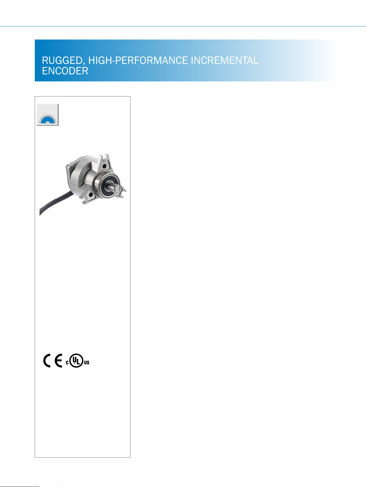
The DKS40 incremental encoder offers
an outstanding price-performance ratio.
Its housing is made of solid zinc die
cast and, with an external diameter of
50 mm, it is extremely compact, saving
At a glance
• Compact diameter
• Rugged, low-cost design
• Interfaces: Open collector NPN, TTL/
• Connection via cable outlet, for radial
RS-422 or HTL/Push Pull.
or axial use with open ends or tted
with an M12 connector
valuable installation space. Use of
mini-disc technology makes the DKS40
extremely resistant to shock and vibration. In addition, the DKS40 has a high
IP 64 enclosure rating.
• Face mount ange with solid shaft
• Housing for simple clamping ring
mounting
• Any number of lines possible from
1 to 2,048
F
Additional information
Fields of application . . . . . . . . . . .F-111
Detailed technical data. . . . . . . . .F-111
Type code. . . . . . . . . . . . . . . . . . . . F-112
Ordering information. . . . . . . . . . . F-113
Dimensional drawings . . . . . . . . .F-114
PIN assignment. . . . . . . . . . . . . . . F-115
Recommended accessories. . . . . F-115
Your benets
• Low-cost encoder with outstanding
quality
• Withstands harsh ambient conditions
due to high IP protection class and
rugged design
• Universal cable outlet enables axial
and radial cable guidance
• Compact dimensions enable simple
installation even where space is
cramped
F-110
ENCODERS | SICK 8015560/2015-09-01
Subject to change without notice
Page 2

Fields of application
• Due to the variety of products, there is a wide range of
application possibilities such as in tool machines, textile
Detailed technical data
Performance
INCREMENTAL ENCODERS DKS40
machines, wood processing machines, packaging machinery
Pulses per revolution
Error limits binary pulses
Error limits non-binary pulses
Measuring step deviation at binary number
1 ... 2,048
0.09°
0.13°
0.035°
of lines
Measuring step deviation at non-binary
0.07°
number of lines
Initialization time
Measurement step
1)
“Binary” number of lines: 2n, where n is a whole number
2)
“Non-binary” number of lines: 2n, where n is not a whole number
40 ms
90° electrical/pulses per revolution
Mechanical data
Mechanical design
Shaft diameter
Mass
Start up torque
Operating torque
Permissible shaft load, radial/axial
Maximum operating speed
Rotor moment of inertia
Bearing lifetime
Max. angular acceleration
Solid shaft
8 mm x 13 mm
0.18 kg
0.6 Ncm (+20 °C)
0.4 Ncm (+20 °C)
40 N, 20 N
6,000 rpm
6 gcm²
2 x 10^9 revolutions
5 x 10^5 rad/s²
1)
2)
F
Electrical data
Electrical interface
Connection type
Operating current without load
Supply voltage
Load current
Maximum output frequency
Open Collector NPN ≤ 50 kHz
TTL/RS422 ≤ 200 kHz
HTL/Push Pull ≤ 200 kHz
1)
The universal cable outlet is positioned so that it is possible to lay it without bends in a radial and axial direction.
2)
This product is a standard product and does not constitute a safety component as dened in the Machinery Directive. Calculation based on nominal load of devices, average ambient temperature 40 °C, frequency of use 8760 h/a. All electronic failures are considered hazardous. For more information, see document no.
8015532.
Subject to change without notice
4.5 … 5.5 V, TTL/RS422, 6 channel
10 … 30 V, HTL/Push Pull, 6 channel
4.5 … 5.5 V, Open Collector NPN, 3 channel
10 … 30 V, Open Collector NPN, 3 channel
Cable, 8-wire, universal outlet, 0.5 m
Cable, 8-wire, universal outlet, 1.5 m
Cable, 8-wire, universal outlet, 3.0 m 1)
Cable, 8-wire, universal outlet, 5.0 m
Cable, 8-pin, universal outlet, 1.5 m, male connector M12
≤ 40 mA
4.5 V ... 5.5 V
10 V ... 30 V
≤ 30 mA
1)
1)
1)
1)
ENCODERS | SICK8015560/2015-09-01
F-111
Page 3

DKS40 INCREMENTAL ENCODERS
Reference signal, number
Reference signal, position
MTTFd: mean time to dangerous failure
1)
The universal cable outlet is positioned so that it is possible to lay it without bends in a radial and axial direction.
2)
This product is a standard product and does not constitute a safety component as dened in the Machinery Directive. Calculation based on nominal load of devices, average ambient temperature 40 °C, frequency of use 8760 h/a. All electronic failures are considered hazardous. For more information, see document no.
8015532.
1
90° electric, logically gated with A and B
600 years (EN ISO 13849-1)
2)
Ambient data
EMC
Enclosure rating as per IEC 60529
Air humidity
Operating temperature range
Storage temperature range
Resistance to shocks
Resistance to vibrations
1)
Condensation of optical surfaces not permitted.
EN 61000-6-2, EN 61000-6-3
IP 64
1)
90%
0 °C ... +60 °C
–40 °C ... +70 °C, without packaging
50 g/ 7 ms (EN 60068-2-27)
20 g / 10 Hz ... 2,000 Hz (EN 60068-2-6)
Type code
Electrical interface
A 4.5 … 5.5 V, TTL/RS422, 6 channel
E 10 … 30 V, HTL/Push Pull, 6 channel
P 4.5 … 5.5 V, Open Collector NPN, 3 channel
R 10 … 30 V, Open Collector NPN, 3 channel
F
Mechanical design
5 Solid solid shaft, face mount ange, Ø 8 mm, length 13 mm
Connection type
J Cable, 8-wire, universal outlet, 0.5 m
K Cable, 8-wire, universal outlet, 1.5 m (no UL approval)
L Cable, 8-wire, universal outlet, 3.0 m (no UL approval)
M Cable, 8-wire, universal outlet, 5.0 m (no UL approval)
P Cable, 8-pin, universal outlet, 1.5 m, male connector M12
Resolution
Always use 5 digits with preceding zeros in clear text
D K S 4 0 -
1)
The universal cable outlet is positioned so that it is possible to lay it without bends in a radial and axial direction.
1)
1)
1)
1)
1)
F-112
ENCODERS | SICK 8015560/2015-09-01
Subject to change without notice
Page 4

INCREMENTAL ENCODERS DKS40
Ordering information
• Mechanical design: solid shaft, face mount ange
Electrical interface Connection type Pulses per revolution Type Part no.
10 DKS40-R5J00010 1034621
20 DKS40-R5J00020 1034622
50 DKS40-R5J00050 1034623
100 DKS40-R5J00100 1034624
200 DKS40-R5J00200 1034625
250 DKS40-R5J00250 1034626
256 DKS40-R5J00256 1034627
10 ... 30 V
Open Collector NPN
4.5 ... 5.5 V
TTL/RS422
Cable, universal, 0.5 m
Cable, universal, 0.5 m
360 DKS40-R5J00360 1034628
500 DKS40-R5J00500 1034629
512 DKS40-R5J00512 1034630
720 DKS40-R5J00720 1034631
800 DKS40-R5J00800 1036154
1,000 DKS40-R5J01000 1034632
1,024 DKS40-R5J01024 1034633
2,000 DKS40-R5J02000 1034813
2,048 DKS40-R5J02048 1034814
4 DKS40-A5J00004 1036293
10 DKS40-A5J00010 1034634
20 DKS40-A5J00020 1034635
50 DKS40-A5J00050 1034636
100 DKS40-A5J00100 1034637
200 DKS40-A5J00200 1034638
250 DKS40-A5J00250 1034639
360 DKS40-A5J00360 1034641
500 DKS40-A5J00500 1034642
512 DKS40-A5J00512 1034643
720 DKS40-A5J00720 1034644
1,000 DKS40-A5J01000 1034645
1,024 DKS40-A5J01024 1034646
2,000 DKS40-A5J02000 1034815
2,048 DKS40-A5J02048 1034816
F
Subject to change without notice
ENCODERS | SICK8015560/2015-09-01
F-113
Page 5

DKS40 INCREMENTAL ENCODERS
Ø 50
42
Electrical interface Connection type Pulses per revolution Type Part no.
10 DKS40-E5J00010 1034647
20 DKS40-E5J00020 1034648
50 DKS40-E5J00050 1034649
100 DKS40-E5J00100 1034650
200 DKS40-E5J00200 1034651
250 DKS40-E5J00250 1034652
10 ... 30 V
HTL/Push Pull
Dimensional drawings (dimensions in mm)
Face mount ange, cable output
256 DKS40-E5J00256 1034653
360 DKS40-E5J00360 1034654
500 DKS40-E5J00500 1034655
512 DKS40-E5J00512 1034656
720 DKS40-E5J00720 1034657
1,000 DKS40-E5J01000 1034658
1,024 DKS40-E5J01024 1034659
2,000 DKS40-E5J02000 1034817
2,048 DKS40-E5J02048 1034818
F
3 x 120°
30°
±0.1
(1.97)
3 x 4.2
(0.17)
+0.1
Ø 33.5
+0.1
27.5 (1.08)
(1.32)
+0.55
13–0.75
(0.51)
(0.98)
Ø 25 f7
(0.31)
Ø 8 m6
±0.1
8
(0.31)
±1
(1.65)
3 x Ø 3.75 H11
(0.15)
General tolerances according to ISO 2768-mk
F-114
ENCODERS | SICK 8015560/2015-09-01
Subject to change without notice
Page 6

PIN assignment
Cable, 8-wire
View of male connector, device side
INCREMENTAL ENCODERS DKS40
PIN, 8-pin, M12
male connector
1 Brown Not assigned ¯A Signal wire
2 White A A Signal wire
3 Black Not assigned ¯B Signal wire
4 Pink B B Signal wire
5 Yellow Not assigned ¯Z Signal wire
6 Violet Z Z Signal wire
7 Blue GND GND Ground connection of the encoder
8 Red +U
Screen Screen Screen Screen
Wire colors OC signal TTL/HTL signal Explanation
S
+U
S
Supply voltage (volt-free to housing)
Screen, connected to housing on the encoder side. Connect-
ed to ground on control side.
F
Subject to change without notice
ENCODERS | SICK8015560/2015-09-01
F-115
Page 7

DKS40 INCREMENTAL ENCODERS
Recommended accessories
Mounting systems
Mounting brackets and plates
Mounting bracket
Figure Brief description Type Part no.
F
Mounting bracket for encoder with centering hub 25 mm, including mounting kit for face
mount ange
BEF-WF-25 2032621
Flanges
Flange plate
Figure Brief description Type Part no.
Flange adapter, adaption of face mount ange with centering hub 20 mm to 33 mm
servo ange, aluminum
Flange adapter, adaption of face mount ange with 25 mm centering hub to size 60 face
mount ange with 36 mm centering hub, aluminum
Flange adapter, adaption of face mount ange with centering hub 25 mm to 50 mm
servo ange, aluminum
Flange adapter, adaption of face mount ange with 25 mm centering hub to 60 mm
square mounting plate, aluminum
Flange adapter, adaptation of face mount ange with 25 mm centering hub to 60 mm
square mounting plate with shock absorbers, aluminum
Flange adapter, adaption of face mount ange with 25 mm centering hub to 63 mm
square mounting plate, aluminum
BEF-FA-020-033 2066312
BEF-FA-025-036 2034226
BEF-FA-025-050 2032622
BEF-FA-025-060RCA 2032623
BEF-FA-025-060RSA 2032624
BEF-FA-025-063-REC 2033631
Other mounting accessories
Mounting bell
Figure Brief description Type Part no.
Mounting bell for encoders with a servo ange, centering collar 50 mm, including mounting kit
BEF-MG-50 5312987
Servo clamps
Figure Brief description Type Part no.
Servo clamps, large, for servo anges (clamps, eccentric fastener), 3 pcs., without
mounting material
BEF-WK-SF 2029166
F-116
ENCODERS | SICK 8015560/2015-09-01
Subject to change without notice
Page 8

INCREMENTAL ENCODERS DKS40
Shaft adaptation
Shaft couplings
Figure Brief description Type Part no.
Bar coupling, shaft diameter 6 mm / 8 mm, maximum shaft offset radial ± 0.3 mm, ax-
ial ± 0.2 mm, angle ± 3°; max. speed 10,000 rpm, torsion spring rigidity 38 Nm/wheel;
material: ber-glass reinforced polyamide, aluminum hub
Bar coupling, shaft diameter 8 mm / 8 mm, maximum shaft offset radial ± 0.3 mm, ax-
ial ± 0.2 mm, angle ± 3°; max. speed 10,000 rpm, torsion spring rigidity 38 Nm/wheel;
material: ber-glass reinforced polyamide, aluminum hub
Bar coupling, shaft diameter 8 mm / 10 mm, maximum shaft offset: radial ± 0.3 mm,
axial ± 0.2 mm, angular ± 3°; torsion spring rigidity 38 Nm/wheel; material: ber-glass
reinforced polyamide, aluminum hub
Double-loop coupling, shaft diameter 8 mm/10 mm, maximum shaft offset: radial
± 2.5 mm, axial ± 3 mm, angular ± 10°; max. speed 3,000 rpm, –30 °C to +80 °C,
max. torque 1.5 Nm; material: polyurethane, galvanized steel ange
Connectivity
Plug connectors and cables
Connecting cables with female connector
KUP-0608-S 5314179
KUP-0808-S 5314177
KUP-0810-S 5314178
KUP-0810-D 5326704
Figure Brief description
Head A: female connector, M12, 8-pin, straight
Head B: cable
Cable: suitable for drag chain, PVC, shielded, 4 x 2 x 0.25 mm², Ø 7.0 mm
Head A: female connector, M23, 12-pin, straight
Head B: cable
Cable: incremental, PUR, shielded, 4 x 2 x 0.25 mm² + 2 x 0.5 mm²
+ 1 x 0.14 mm², Ø 7.8 mm
Head A: female connector, M23, 12-pin, straight
Head B: cable
Cable: incremental, suitable for drag chain, PUR, shielded, 4 x 2 x 0.25 mm²
+ 2 x 0.5 mm² + 1 x 0.14 mm², Ø 7.8 mm
1)
Warning! Only in combination with electrical interfaces A, C, E and P.
1)
Length
Type Part no.
of
cable
2 m DOL-1208-G02MAC1
5 m DOL-1208-G05MAC1
10 m DOL-1208-G10MAC1
20 m DOL-1208-G20MAC1
2 m DOL-2312-G02MLA3 2030682
7 m DOL-2312-G07MLA3 2030685
10 m DOL-2312-G10MLA3 2030688
1)
15 m DOL-2312-G15MLA3 2030692
20 m DOL-2312-G20MLA3 2030695
25 m DOL-2312-G25MLA3 2030699
30 m DOL-2312-G30MLA3 2030702
1.5 m DOL-2312-G1M5MA3
3 m DOL-2312-G03MMA3
5 m DOL-2312-G05MMA3
10 m DOL-2312-G10MMA3
20 m DOL-2312-G20MMA3
30 m DOL-2312-G30MMA3
6032866
6032867
6032868
6032869
F
2029212
2029213
2029214
2029215
2029216
2029217
Subject to change without notice
ENCODERS | SICK8015560/2015-09-01
F-117
Page 9

DKS40 INCREMENTAL ENCODERS
Female connectors (ready to assemble)
Figure Brief description Type Part no.
Head A: female connector, M23, 12-pin, straight, shielded, for cable diameter
5.5 mm ... 10.5 mm
Head B: Operating temperature:
–20 °C ... +130 °C
Head A: female connector, M23, 12-pin, angled, shielded, for cable diameter
4.2 mm ... 6.6 mm
Head B: Operating temperature:
–20 °C ... +130 °C
Head A: female connector, M23, 12-pin, straight, shielded, for cable diameter
5.5 mm ... 10.5 mm
Head B: Operating temperature:
–40 °C ... +125 °C
Cables (ready to assemble)
DOS-2312-G
DOS-2312-W01
DOS-2312-G02
6027538
2072580
2077057
F
Figure Brief description Length
Type Part no.
of
cable
Head A: cable
Head B: cable
Cable: suitable for drag chain, PUR, halogen-free, shielded, 4 x 2 x 0.15 mm²,
Ø 5.6 mm
Head A: cable
Head B: cable
Cable: PUR, shielded, 4 x 2 x 0.25 mm² + 2 x 0.5 mm² + 1 x 0.14 mm²,
Ø 7.5 mm
Head A: cable
Head B: cable
Cable: suitable for drag chain, PUR, halogen-free, shielded, 4 x 2 x 0.25 mm²
+ 2 x 0.5 mm² + 2 x 0.14 mm², Ø 7.8 mm
Head A: cable
Head B: cable
Cable: suitable for drag chain, PUR, halogen-free,
shielded, UV and saltwater resistant, 4 x 2 x
0.25 mm² + 2 x 0.5 mm² + 2 x 0.14 mm², Ø 7.8 mm
By the
meter
LTG-2308-MWENC 6027529
LTG-2411-MW 6027530
LTG-2512-MW 6027531
LTG-2612-MW 6028516
Male connector (ready to assemble)
Figure Brief description Type Part no.
Head A: male connector, M23, 12-pin, straight, shielded, for cable diameter
5.5 mm ... 10.5 mm
Head B:
Operating temperature: –20 °C ... +130 °C
Head A: male connector, M23, 12-pin, straight, for cable diameter 5.5 mm ... 10.5 mm
Head B: Operating temperature:
–40 °C ... +125 °C
- For additional accessories, please see page K-668 onwards
STE-2312-G 6027537
STE-2312-G01 2077273
F-118
ENCODERS | SICK 8015560/2015-09-01
Subject to change without notice
Page 10

INCREMENTAL ENCODERS DKS40
F
Subject to change without notice
ENCODERS | SICK8015560/2015-09-01
F-119
 Loading...