

DFS60 INCREMENTAL ENCODERS
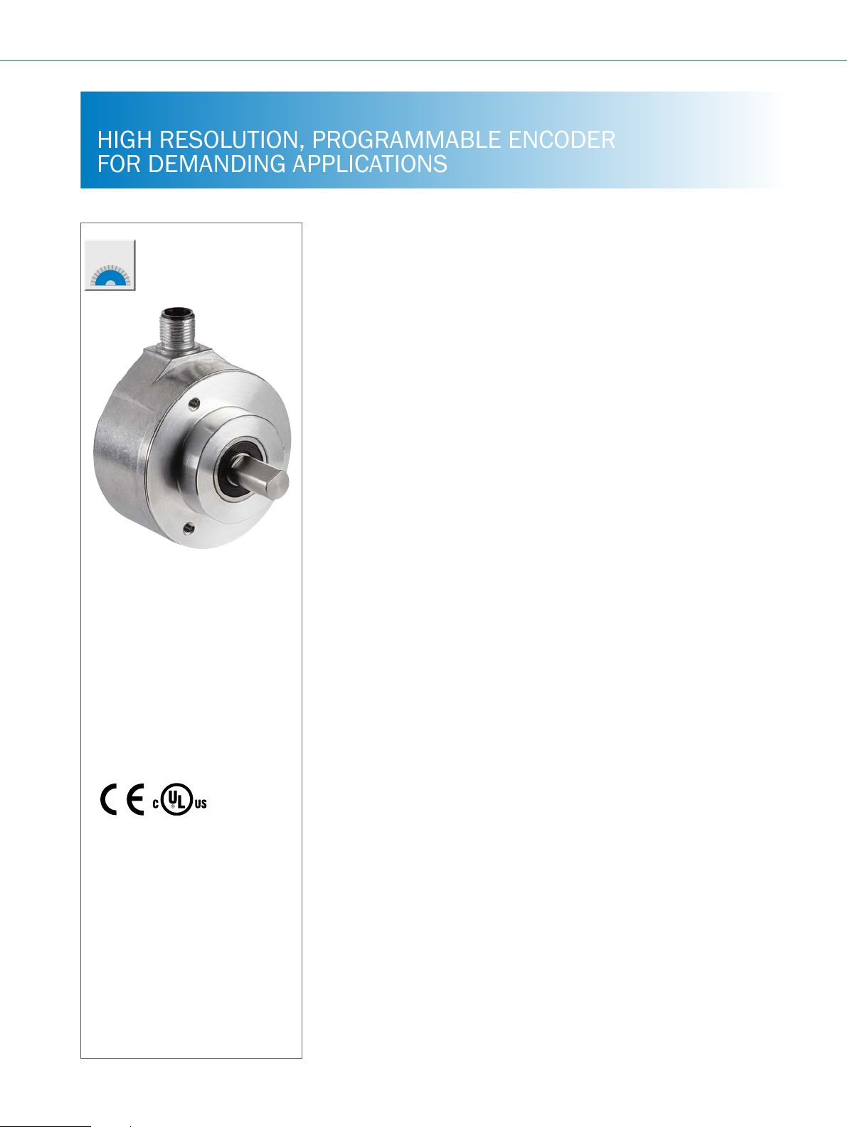
HIGH RESOLUTION, PROGRAMMABLE ENCODER
FOR DEMANDING APPLICATIONS
Product description
The DFS60 is a high-resolution incremental encoder with a diameter of 60 mm.
It offers a wide variety of mechanical
and electric interfaces and can also be
programmed by the customer if required.
Programming of the output signal and
zero pulse is a unique feature for the
At a glance
• Short installation depth
• High resolution of up to 16 bits
• Optional programming: output volt-
age, zero pulse position, zero impulse
width and pulse count.
• Connection: radial or axial cable
outlet, M23 or M12 male connector,
axial or radial.
market. The high enclosure rating, wide
temperature range, and large ball bearing distance ensure extreme reliability,
making the DFS60 the ideal encoder for
industrial applications in harsh environments.
• Electrical interfaces: 5 V & 24 V TTL/
RS-422, 24 V HTL/Push Pull
• Mechanical interfaces: face mount
ange or servo ange, blind hollow
shaft or through hollow shaft
• Remote zero set possible
F
Additional information
Fields of application . . . . . . . . . . .F-163
Detailed technical data. . . . . . . . .F-163
Viewing number of resolutions. . . F-167
Type code. . . . . . . . . . . . . . . . . . . . F-167
Dimensional drawings . . . . . . . . .F-174
Proposed tting . . . . . . . . . . . . . . . F-182
PIN assignment. . . . . . . . . . . . . . . F-182
Interfaces....................F-183
Recommended accessories. . . . . F-185
Your benets
• Reduction of storage costs and down-
times due to programmability by the
customer
• The wide range of different mechani-
cal and electrical interfaces enables
the
optimum adaptation of the encoder
to the application-specic installation
situation
• Excellent concentricity even at high
speeds
• High resolution of up to 16 bits
ensures precise measurements for
demanding applications
• Long-term and reliable operation
thanks to a high enclosure rating,
temperature resistance and bearing
lifetime
• The ability to program using the
PGT-08-S programming software and
the PGT-10-Pro display programming
device
enables fast and exible adaptation
of the encoder to customer requirements
• Programmable zero pulse position
simplies installation
F-162
ENCODERS | SICK 8015560/2015-09-01
Subject to change without notice

Fields of application
• Applications in factory and logistics automation for measur-
ing position, speed, and distance: e.g., in printing machines,
Detailed technical data
Performance
Eco Basic Advanced
Pulses per revolution
1) 2)
Pulses per revolution at sin/cos
1.0 V
ss
Measurement step
Measuring step deviation at non-binary
number of lines
Pulses 1 ... 99 – ± 0.08° ± 0.04°
Pulses 100 ... 10,000 ± 0.2° ± 0.01° ± 0.008°
Pulses > 10,000 – ± 0.002°
Measuring step deviation at binary number
of lines
Pulses 1 ... 64 – ± 0.05° ± 0.03°
Pulses 128 ... 8,192 ± 0.15° ± 0.008° ± 0.008°
Pulses 16,384 ... 65,536 – ± 0.0015°
Reference signal
Number 1
Location 90°, electric, logically gated with A and B/sine and cosine
Error limits
1)
See maximum viewing number of resolutions
2)
For a detailed list see “Pulses per revolution”
3)
Under mechanical zero set width.
100 ... 2,048 1 ... 10,000 1 ... 65,536
– 1,024 –
90° electrical/pulses per revolution
± 0.3° ± 0.05° ± 0.03°
INCREMENTAL ENCODERS DFS60
textile machines, wood processing, packaging machinery
F
Electrical data
Eco Basic Advanced
Electrical interface
1)
Factory setting, output level TTL.
2)
Only with device variants with M23 male connector outlet in conjunction with the electrical interfaces M,U,V and W.
3)
Under mechanical zero set width.
4)
The universal cable outlet is positioned so that it is possible to lay it without bends in a radial or axial direction.
5)
Short-circuit of another channel US or GND permissible for a maximum of 30 s.
6)
Short-circuit of another channel or GND permissible for a maximum of 30 s.
7)
TTL programming with ≥ 5.5 V: Short-circuit of another channel or GND permissible for a maximum of 30 s.
8)
HTL or TTL programming with< 5.5 V: Short-circuit of another channel, US or GND permissible for a maximum of 30 s.
9)
This product is a standard product and does not constitute a safety component as dened in the Machinery Directive. Calculation based on nominal load of devices, average ambient temperature 40 °C, frequency of use 8760 h/a. All electronic failures are considered hazardous. For more information, see document no.
8015532.
4.5 V ... 5.5 V, TTL/RS422
10 V ... 32 V, HTL/Push Pull
10 V ... 32 V, TTL/RS422
– 4.5 V … 5.5 V, sin/cos 1.0 V
SS
– 4.5 V ... 32 V, HTL/Push Pull, 0-SET on M23 male connector
– 4.5 V ... 5.5 V, TTL/RS422, 0-SET on M23 male connector
– 4.5 V ... 32 V, TTL/RS422, 0-SET on M23 male connector
– 4.5 V ... 32 V, TTL/HTL programmable
– 4.5 V ... 32 V, TTL/HTL programmable, 0-SET on M23 male
connector
1) 2)
1)
2)
2)
2)
Subject to change without notice
ENCODERS | SICK8015560/2015-09-01
F-163

F
DFS60 INCREMENTAL ENCODERS
Eco Basic Advanced
Initialization time after power on
4.5 V ... 5.5 V, TTL/RS422 40 ms
10 V ... 32 V, HTL/Push Pull 40 ms
10 V ... 32 V, TTL/RS422 40 ms
4.5 V … 5.5 V, sin/cos 1.0 V
4.5 V ... 32 V, HTL/Push Pull, 0-SET – Max. 30 ms
4.5 V ... 5.5 V, TTL/RS422, 0-SET – Max. 30 ms
4.5 V ... 32 V, TTL/RS422, 0-SET – Max. 30 ms
4.5 V ... 32 V, TTL/HTL programmable – Max. 30 ms/32 ms
4.5 V ... 32 V, TTL/HTL programmable, 0-SET – Max. 30 ms/32 ms
0-set function
Connection type
Max. load current
Operating current without load
Load resistance
4.5 V … 5.5 V, sin/cos 1.0 VSS– min. 120 Ω –
Max. power consumption without load
10 V ... 32 V, HTL/Push Pull 0.5 W
10 V ... 32 V, TTL/RS422 0.5 W
4.5 V ... 32 V, HTL/Push Pull, 0-SET – 0.7 W
4.5 V ... 5.5 V, TTL/RS422, 0-SET – 0.7 W
4.5 V ... 32 V, TTL/RS422, 0-SET – 0.7 W
4.5 V ... 32 V, TTL/HTL programmable – 0.7 W
4.5 V ... 32 V, TTL/HTL programmable, 0-SET – 0.7 W
Maximum output frequency
TTL/RS422 300 kHz 600 kHz 820 kHz
HTL/Push Pull 300 kHz 600 kHz 820 kHz
HTL/Push Pull, 0-SET 300 kHz 600 kHz 820 kHz
TTL/RS422, 0-SET 300 kHz 600 kHz 820 kHz
TTL/HTL programmable – 600 kHz 820 kHz
Sin/cos 1.0 V
TTL/HTL programmable, 0-SET – 600 kHz 820 kHz
1)
Factory setting, output level TTL.
2)
Only with device variants with M23 male connector outlet in conjunction with the electrical interfaces M,U,V and W.
3)
Under mechanical zero set width.
4)
The universal cable outlet is positioned so that it is possible to lay it without bends in a radial or axial direction.
5)
Short-circuit of another channel US or GND permissible for a maximum of 30 s.
6)
Short-circuit of another channel or GND permissible for a maximum of 30 s.
7)
TTL programming with ≥ 5.5 V: Short-circuit of another channel or GND permissible for a maximum of 30 s.
8)
HTL or TTL programming with< 5.5 V: Short-circuit of another channel, US or GND permissible for a maximum of 30 s.
9)
This product is a standard product and does not constitute a safety component as dened in the Machinery Directive. Calculation based on nominal load of devices, average ambient temperature 40 °C, frequency of use 8760 h/a. All electronic failures are considered hazardous. For more information, see document no.
8015532.
– 40 ms –
SS
3)
3)
H – active (L = 0 ... 3 V, H = 4 ... Us V)
Cable, 8-wire, universal, 1.5 m
Cable, 8-wire, universal, 3 m
Cable, 8-wire, universal, 5 m
4)
4)
4)
M12 male connector, 8-pin, radial
M12 male connector, 8-pin, axial
M23 male connector, 12-pin, radial
M23 male connector, 12-pin, axial
≤ 30 mA
40 mA
– 200 kHz –
SS
F-164
ENCODERS | SICK 8015560/2015-09-01
Subject to change without notice

INCREMENTAL ENCODERS DFS60
Eco Basic Advanced
Reverse polarity protection
4.5 V...5.5 V, TTL/RS422 –
10 V ... 32 V, HTL/Push Pull
10 V ... 32 V, TTL/RS422
4.5 V … 5.5 V, sin/cos 1.0 V
4.5 V ... 32 V, HTL/Push Pull, 0-SET –
4.5 V ... 5.5 V, TTL/RS422, 0-SET –
4.5 V ... 32 V, TTL/RS422, 0-SET –
4.5 V ... 32 V, TTL/HTL programmable –
4.5 V ... 32 V, TTL/HTL programmable, 0-SET –
Short-circuit protection of the outputs
4.5 V–5.5 V, TTL/RS422
10 V ... 32 V, HTL/Push Pull
10 V ... 32 V, TTL/RS422
4.5 V ... 32 V, HTL/Push Pull, 0-SET –
4.5 V ... 5.5 V, TTL/RS422, 0-SET –
4.5 V ... 32 V, TTL/RS422, 0-SET –
4.5 V ... 32 V, TTL/HTL programmable –
4.5 V … 5.5 V, sin/cos 1.0 VSS–
4.5 V ... 32 V, TTL/HTL programmable, 0-SET –
MTTFd: mean time to dangerous failure
1)
Factory setting, output level TTL.
2)
Only with device variants with M23 male connector outlet in conjunction with the electrical interfaces M,U,V and W.
3)
Under mechanical zero set width.
4)
The universal cable outlet is positioned so that it is possible to lay it without bends in a radial or axial direction.
5)
Short-circuit of another channel US or GND permissible for a maximum of 30 s.
6)
Short-circuit of another channel or GND permissible for a maximum of 30 s.
7)
TTL programming with ≥ 5.5 V: Short-circuit of another channel or GND permissible for a maximum of 30 s.
8)
HTL or TTL programming with< 5.5 V: Short-circuit of another channel, US or GND permissible for a maximum of 30 s.
9)
This product is a standard product and does not constitute a safety component as dened in the Machinery Directive. Calculation based on nominal load of devices, average ambient temperature 40 °C, frequency of use 8760 h/a. All electronic failures are considered hazardous. For more information, see document no.
8015532.
l
l
–
SS
5)
l
5)
l
6)
l
300 years (EN ISO 13849-1)
l
l
l
l
l
7)
l
7)
l
8)
l
7) 8)
l
5)
l
7) 8)
l
9)
–
F
Mechanical data
Eco Basic Advanced
Shaft diameter
Face mount ange 6 mm x 10 mm
Servo ange 10 mm x 19 mm
Blind hollow shaft, through hollow shaft 2)6 mm, 8 mm, 10 mm, 12 mm, 14 mm, 15 mm, 3/8", 1/2", 5/8"
3)
Mass
Solid shaft 0.3 kg
Blind hollow shaft, through hollow shaft 0.2 kg
Shaft material
Flange material
Housing material
1)
Other diameter, lengths, and spread shafts on request.
2)
Clamping on the back of the shaft on request.
3)
Relates to devices with cable outlet.
4)
Stainless steel on request.
5)
Take into account self-heating of 3.3 K per 1,000 revolutions/min when designing the operating temperature range.
Subject to change without notice
Stainless steel
Aluminum
Aluminum die cast
1)
1)
4)
4)
ENCODERS | SICK8015560/2015-09-01
F-165

F
DFS60 INCREMENTAL ENCODERS
Eco Basic Advanced
Start up torque
Solid shaft 0.5 Ncm (+20 °C)
Blind hollow shaft, through hollow shaft 0.8 Ncm (+20 °C)
Operating torque
Solid shaft 0.3 Ncm (+20 °C)
Blind hollow shaft, through hollow shaft 0.6 Ncm (+20 °C)
Permissible shaft movement, axial static/
dynamic
Blind hollow shaft, through hollow shaft ± 0.5 mm, ± 0.2 mm ± 0.5 mm, ± 0.01 mm
Permissible shaft movement, radial static/
dynamic
Blind hollow shaft, through hollow shaft ± 0.3 mm, ± 0.1 mm ± 0.3 mm, ± 0.05 mm
Permissible shaft loading
Solid shaft 80 N (radial)
40 N (axial)
Maximum operating speed
Solid shaft 9,000 / min
Blind hollow shaft, through hollow shaft 6,000 / min
Rotor moment of inertia
Solid shaft 6.2 gcm²
Blind hollow shaft, through hollow shaft 40 gcm²
Bearing lifetime
Max. angular acceleration
1)
Other diameter, lengths, and spread shafts on request.
2)
Clamping on the back of the shaft on request.
3)
Relates to devices with cable outlet.
4)
Stainless steel on request.
5)
Take into account self-heating of 3.3 K per 1,000 revolutions/min when designing the operating temperature range.
3.6 x 10¹⁰ revolutions
5 x 10⁵ rad/s²
5)
5)
Ambient data
Eco Basic Advanced
1)
EMC
Enclosure rating as per IEC 60529
On the shaft IP 65
On the housing, male connector outlet 3)IP 67 (IP 65 for through hollow shaft)
On the housing, cable outlet IP 67 (IP 65 for through hollow shaft)
Permissible relative humidity
Operating temperature range
Storage temperature range
Resistance to shocks according to
EN 60068-2-27
Resistance to vibration according to
EN 60068-2-6
1)
For interfaces 10 ... 32 V, TTL/RS422 and 10 ... 32 V, HTL/Push Pull according to EN 61000-6-2 and EN 61000-6-4, devices in class A
2)
IP 67 on request.
3)
When mating connector is inserted.
4)
When cables are xed in place.
5)
When cables can be moved.
According to EN 61000-6-2 and EN 61000-6-3
2)
90% (condensation of optical surfaces not permitted)
0 °C ... +85 °C –40 °C ... +100 °C
–30 °C ... +100 °C
4)
5)
–40 °C ... +100 °C, without packaging
50 g 70 g 100 g
20 g, 10 Hz ... 2,000 Hz 30 g, 10 Hz ... 2,000 Hz
F-166
ENCODERS | SICK 8015560/2015-09-01
Subject to change without notice
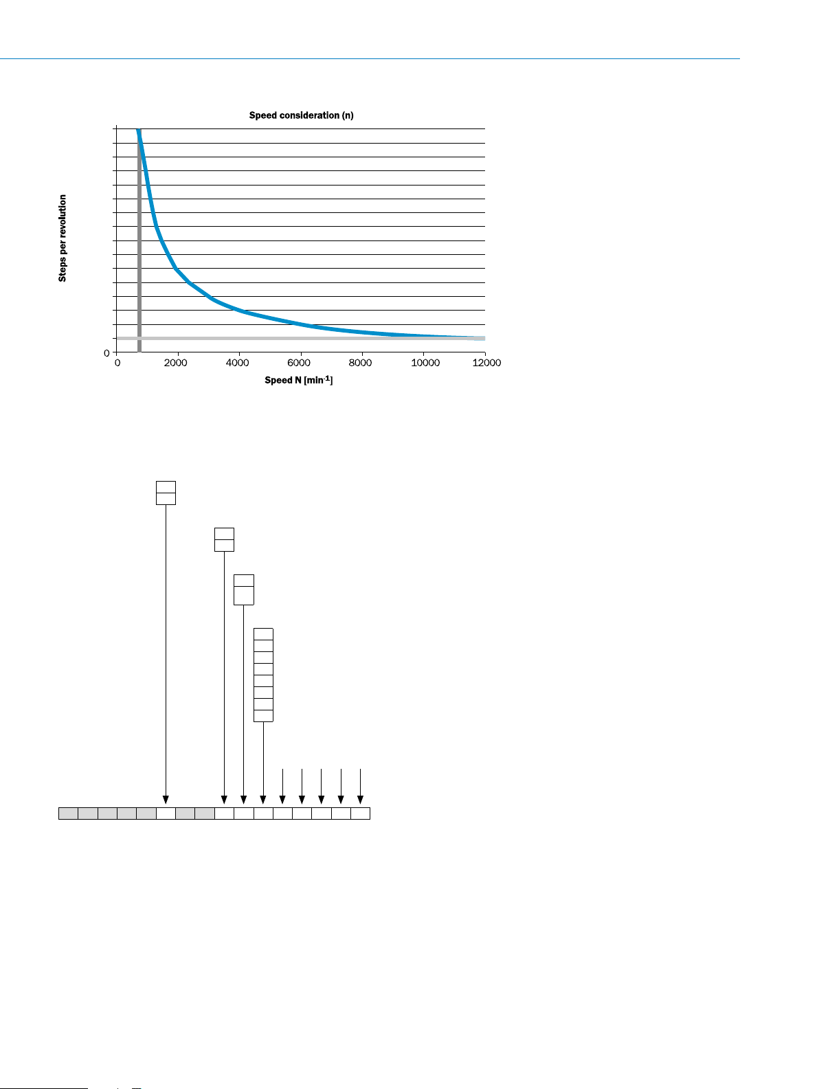
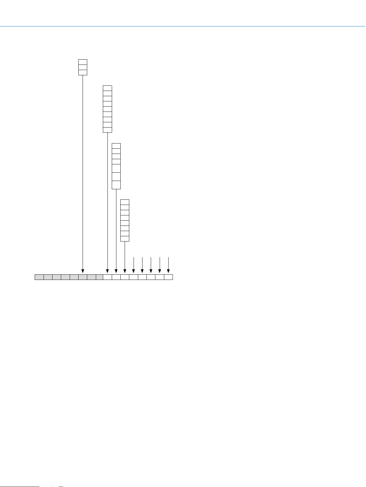
Viewing number of resolutions
65536
61440
57344
53248
49152
45056
40960
36864
32768
28672
24576
20480
16384
12288
8192
4096
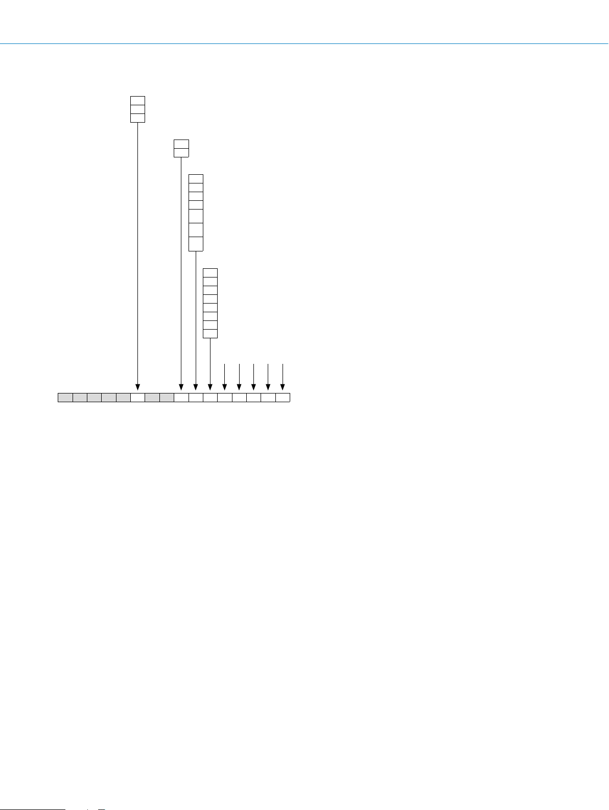
Type code
Solid shaft, programmable
INCREMENTAL ENCODERS DFS60
Type
B Pulses per revolution, programmable, 1 … 10,000
A Pulses per revolution, programmable, 1 … 65,536
Mechanical design
4 Face mount ange, solid shaft 10 x 19 mm
1 Servo ange, solid shaft 6 x 10 mm
Electrical interface (factory setting: output level TTL)
P 4.5 V ... 32 V, TTL/HTL programmable
4.5 … 32 V, TTL or HTL programmable with O-set function on PIN 7 on M23 male connector. (Only in combination with
M
connection type A or B)
Connection type
A Male connector M23, 12-pin, radial
B Male connector M23, 12-pin, axial
C Male connector M12, 8-pin, radial
D Male connector M12, 8-pin, axial
K Cable, 8-wire, universal, 1.5 m
L Cable, 8-wire, universal, 3 m
M Cable, 8-wire, universal, 5 m
N Cable, 8-wire, universal, 10 m
Resolution
(Factory setting for pulses per revolution for type B: 10,000; 65,536 for type A)
Always use 5 digits in clear text, see “Pulses per revolution”
D F S 6 0 - S
1)
The universal cable outlet is positioned so that it is possible to lay it without bends in a radial and axial direction.
1)
1)
1)
1)
The following features can be programmed:
Pulses per revolution from 1 ... 65,536 using the programming tools PGT-08-S or PGT-10-Pro
Electrical zero-pulse width 90°, 180°, 270° using the programming tools PGT-08-S or PGT-10-Pro
Mechanical zero-pulse width 1° ... 359° using the programming tool PGT-10-Pro
Output voltage levels for TTL or HTL using the programming tools PGT-08-S or PGT-10-Pro
Counting direction CW/CCW using the programming tools PGT-08-S or PGT-10-Pro
0-SET function using the programming tools PGT-08-S or PGT-10-Pro
0-SET function via PIN 7 of the M23 male connector by applying U
for at least 250 ms.
s
F
Subject to change without notice
ENCODERS | SICK8015560/2015-09-01
F-167
DFS60 INCREMENTAL ENCODERS
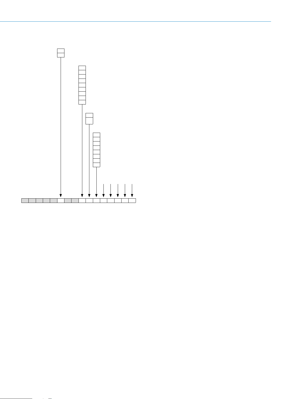
Solid shaft, not programmable
Type
E Pulses per revolution: 100 ... 2,048
B Pulses per revolution, 1 … 10,000
A Pulses per revolution, 1 … 65,536
Mechanical design
4 Face mount ange, solid shaft 10 x 19 mm
1 Servo ange, solid shaft 6 x 10 mm
Electrical interface
A 4.5 V...5.5 V, TTL/RS422
C 10 V...32 V, TTL/RS422
E 10 ... 32 V, HTL/Push Pull
N 4.5 … 5.5 V, SIN/COS 1.0 V
4.5 … 5.5 V, TTL/RS422 with O-set function on PIN 7 on M23 male connector. (In combination with type B or A and
U
connection type A or B only)
4.5 … 32 V, TTL/RS422 with O-set function on PIN 7 on M23 male connector. (In combination with type B and A and
V
connection type A or B only)
4.5 … 32 V, HTL/Push Pull with O-set function on PIN 7 on M23 male connector. (In combination with type B and A and
W
connection type A or B only)
Connection type
A Male connector M23, 12-pin, radial
B Male connector M23, 12-pin, axial
C Male connector M12, 8-pin, radial
D Male connector M12, 8-pin, axial
K Cable, 8-wire, universal, 1.5 m
L Cable, 8-wire, universal, 3 m
M Cable, 8-wire, universal, 5 m
N Cable, 8-wire, universal, 10 m
(in combination with type B and 1,024 pulses only)
SS
1)
1)
1)
1)
F
Resolution
Always use 5 digits in clear text, see “Pulses per revolution”
D F S 6 0 - S
1)
The universal cable outlet is positioned so that it is possible to lay it without bends in a radial and axial direction.
F-168
ENCODERS | SICK 8015560/2015-09-01
Subject to change without notice
Blind hollow shaft, programmable
Type
B Pulses per revolution, programmable, 1 … 10,000
A Pulses per revolution, programmable, 1 … 65,536
Mechanical design
A Blind hollow shaft, 6 mm
B Blind hollow shaft, 8 mm
C Blind hollow shaft, 3/8"
D Blind hollow shaft, 10 mm
E Blind hollow shaft, 12 mm
F Blind hollow shaft, 1/2"
G Blind hollow shaft, 14 mm
H Blind hollow shaft, 15 mm
J Blind hollow shaft, 5/8" (suitable for holding collets, see “Accessories”)
INCREMENTAL ENCODERS DFS60
Electrical interface (factory setting: output level TTL)
P 4.5 V ... 32 V, TTL/HTL programmable
4.5 … 32 V, TTL or HTL programmable with O-set function on PIN 7 on M23 male connector. (Only in combination with
M
connection type A or B)
Connection type
A Male connector M23, 12-pin, radial
B Male connector M23, 12-pin, axial
C Male connector M12, 8-pin, radial
D Male connector M12, 8-pin, axial
K Cable, 8-wire, universal, 1.5 m
L Cable, 8-wire, universal, 3 m
M Cable, 8-wire, universal, 5 m
N Cable, 8-wire, universal, 10 m
1)
1)
1)
1)
Resolution
(Factory setting for pulses per revolution for type B: 10,000; 65,536 for type A)
Always use 5 digits in clear text, see “Pulses per revolution”
D F S 6 0 - B
1)
The universal cable outlet is positioned so that it is possible to lay it without bends in a radial and axial direction.
The following features can be programmed:
Pulses per revolution from 1 ... 65,536 using the programming tools PGT-08-S or PGT-10-Pro
Electrical zero-pulse width 90°, 180°, 270° using the programming tools PGT-08-S or PGT-10-Pro
Mechanical zero-pulse width 1° ... 359° using the programming tool PGT-10-Pro
Output voltage levels for TTL or HTL using the programming tools PGT-08-S or PGT-10-Pro
Counting direction CW/CCW using the programming tools PGT-08-S or PGT-10-Pro
0-SET function using the programming tools PGT-08-S or PGT-10-Pro
0-SET function via PIN 7 of the M23 male connector by applying U
for at least 250 ms.
s
F
Subject to change without notice
ENCODERS | SICK8015560/2015-09-01
F-169
F
DFS60 INCREMENTAL ENCODERS
Blind hollow shaft, not programmable
Type
E Pulses per revolution: 100 ... 2,048
B Pulses per revolution, 1 … 10,000
A Pulses per revolution, 1 … 65,536
Mechanical design
A Blind hollow shaft, 6 mm
B Blind hollow shaft, 8 mm
C Blind hollow shaft, 3/8"
D Blind hollow shaft, 10 mm
E Blind hollow shaft, 12 mm
F Blind hollow shaft, 1/2"
G Blind hollow shaft, 14 mm
H Blind hollow shaft, 15 mm
J Blind hollow shaft, 5/8" (suitable for holding collets, see “Accessories”)
Electrical interface
A 4.5 V...5.5 V, TTL/RS422
C 10 V...32 V, TTL/RS422
E 10 ... 32 V, HTL/Push Pull
N 4.5 … 5.5 V, SIN/COS 1.0 V
4.5 … 5.5 V, TTL/RS422 with O-set function on PIN 7 on M23 male connector. (In combination with type B or A and
U
connection type A or B only)
4.5 … 32 V, TTL/RS422 with O-set function on PIN 7 on M23 male connector. (In combination with type B and A
V
and connection type A or B only)
4.5 … 32 V, HTL/Push Pull with O-set function on PIN 7 on M23 male connector. (In combination with type B and A
W
and connection type A or B only)
Connection type
A Male connector M23, 12-pin, radial
B Male connector M23, 12-pin, axial
C Male connector M12, 8-pin, radial
D Male connector M12, 8-pin, axial
K Cable, 8-wire, universal, 1.5 m
L Cable, 8-wire, universal, 3 m
M Cable, 8-wire, universal, 5 m
N Cable, 8-wire, universal, 10 m
Resolution
Always use 5 digits in clear text, see “Pulses per revolution”
(in combination with type B and 1,024 pulses only)
SS
1)
1)
1)
1)
D F S 6 0 - B
1)
The universal cable outlet is positioned so that it is possible to lay it without bends in a radial and axial direction.
F-170
ENCODERS | SICK 8015560/2015-09-01
Subject to change without notice

Through hollow shaft, programmable
Type
B Pulses per revolution, programmable, 1 … 10,000
A Pulses per revolution, programmable, 1 … 65,536
Mechanical design
A Through hollow shaft, 6 mm
B Through hollow shaft, 8 mm
C Through hollow shaft, 3/8"
D Through hollow shaft, 10 mm
E Through hollow shaft, 12 mm
F Through hollow shaft 1/2"
G Through hollow shaft, 14 mm
H Through hollow shaft, 15 mm
J Through hollow shaft, 5/8" (suitable for holding collets, see “Accessories”)
Electrical interface (factory setting: output level TTL)
INCREMENTAL ENCODERS DFS60
P 4.5 V ... 32 V, TTL/HTL programmable
4.5 … 32 V, TTL or HTL programmable with O-set function on PIN 7 on M23 male connector. (Only in combination with
M
connection type A)
Connection type
A Male connector M23, 12-pin, radial
C Male connector M12, 8-pin, radial
K Cable, 8-wire, universal, 1.5 m
L Cable, 8-wire, universal, 3 m
M Cable, 8-wire, universal, 5 m
N Cable, 8-wire, universal, 10 m
1)
1)
1)
1)
Resolution
(Factory setting for pulses per revolution for type B: 10,000; 65,536 for type A)
Always use 5 digits in clear text, see “Pulses per revolution”
D F S 6 0 - T
1)
The universal cable outlet is positioned so that it is possible to lay it without bends in a radial and axial direction.
The following features can be programmed:
Pulses per revolution from 1 ... 65,536 using the programming tools PGT-08-S or PGT-10-Pro
Electrical zero-pulse width 90°, 180°, 270° using the programming tools PGT-08-S or PGT-10-Pro
Mechanical zero-pulse width 1° ... 359° using the programming tool PGT-10-Pro
Output voltage levels for TTL or HTL using the programming tools PGT-08-S or PGT-10-Pro
Counting direction CW/CCW using the programming tools PGT-08-S or PGT-10-Pro
0-SET function using the programming tools PGT-08-S or PGT-10-Pro
0-SET function via PIN 7 of the M23 male connector by applying U
for at least 250 ms
s
F
Subject to change without notice
ENCODERS | SICK8015560/2015-09-01
F-171

DFS60 INCREMENTAL ENCODERS
Through hollow shaft, not programmable
Type
E Pulses per revolution: 100 ... 2,048
B Pulses per revolution, 1 … 10,000
A Pulses per revolution, 1 … 65,536
Mechanical design
A Through hollow shaft, 6 mm
B Through hollow shaft, 8 mm
C Through hollow shaft, 3/8"
D Through hollow shaft, 10 mm
E Through hollow shaft, 12 mm
F Through hollow shaft, 1/2"
G Through hollow shaft, 14 mm
H Through hollow shaft, 15 mm
J Through hollow shaft, 5/8" (suitable for holding collets, see “Accessories”)
Electrical interface
A 4.5 V...5.5 V, TTL/RS422
C 10 V...32 V, TTL/RS422
E 10 ... 32 V, HTL/Push Pull
N 4.5 … 5.5 V, SIN/COS 1.0 V
4.5 … 5.5 V, TTL/RS422 with O-set function on PIN 7 on M23 male connector. (In combination with type B or A and
U
connection type A only)
4.5 … 32 V, TTL/RS422 with O-set function on PIN 7 on M23 male connector. (In combination with type B and A and
V
connection type A only)
4.5 … 32 V, HTL/Push Pull with O-set function on PIN 7 on M23 male connector. (In combination with type B and A and
W
connection type A only)
Connection type
A Male connector M23, 12-pin, radial
C Male connector M12, 8-pin, radial
K Cable, 8-wire, universal, 1.5 m
L Cable, 8-wire, universal, 3 m
M Cable, 8-wire, universal, 5 m
N Cable, 8-wire, universal, 10 m
(in combination with type B and 1,024 pulses only)
SS
1)
1)
1)
1)
F
Resolution
Always use 5 digits in clear text, see “Pulses per revolution”
D F S 6 0 - T
1)
The universal cable outlet is positioned so that it is possible to lay it without bends in a radial and axial direction.
F-172
ENCODERS | SICK 8015560/2015-09-01
Subject to change without notice

INCREMENTAL ENCODERS DFS60
Pulses per revolution
1)
E B
00100 00100 00100
00200 00200 00200
00250 00250 00250
00256 00300 00300
00314 00314 00314
00360 00360 00360
00500 00500 00500
00512 00512 00512
00720 00720 00720
01000 01000 01000
01024 01024 01024
01250 01250 01250
Pulses per revolution
1) T
he electrical interface N (Sin/Cox 1.0 VSS) can only be ordered with 1,024 pulses per revolution.
2)
Additional available upon request.
02000 02000 02000
02048 02048 02048
2)
02500 02500
03600 03600
04000 04000
04096 04096
05000 05000
07200 07200
08192 08192
10000 10000
2)
A
16384
32768
65536
F
Subject to change without notice
ENCODERS | SICK8015560/2015-09-01
F-173

DFS60 INCREMENTAL ENCODERS
(0.75)
Ø 0.1
C
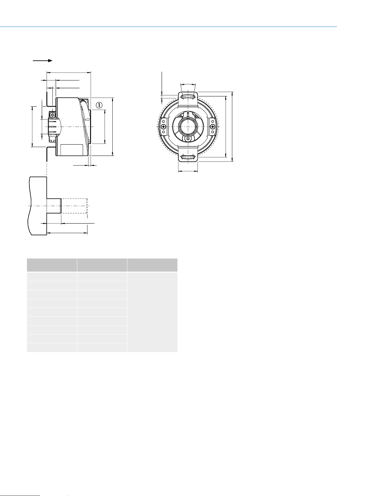
Dimensional drawings (dimensions in mm)
Face mount ange, cable output
A
10
Ø 0.05
B
C
Ø 10
Ø 36
(1.42) f8
B
0.03
A
General tolerances according to ISO 2768-mk
1 Cable diameter = 5.6 mm +/- 0.2 mm bend radius = 30 mm
18
(0.39) f7
(0.71)
9
(0.35)
±0.3
19
(0.39)
Ø 0.1
A
43.1 (1.70)
A
Ø 60 (2.36)
Face mount ange, radial cable outlet M12 and M23
A
3 x 120°
Ø 0.05
3 x M4
(6-deep)
±0.05 (1.89)
Ø 48
C
F
Ø 0.05
B
40.1 (1.58)
10 (0.39)
C
Ø 10
Ø 36
(1.42) f8
B
0.03
A
General tolerances according to ISO 2768-mk
18
(0.39) f7
(0.71)
±0.3
19
(0.75)
A
9
(0.35)
0.1
A
14.5
(0.57)
Ø 60 (2.36)
7.75
(0.31)
M12 x 1
26.1
(1.03)
M23 x 1
(3x) 120°
13
(0.51)
25°
±2°
3 x M4
(6-deep)
(1.89)
±0.05
Ø 48
F-174
ENCODERS | SICK 8015560/2015-09-01
Subject to change without notice

Face mount ange, axial cable outlet M12 and M23
Ø 36 f8 (1.42)
5.
INCREMENTAL ENCODERS DFS60
Ø 0.05 A
0.1 A
18
(0.39)
9
C
Ø 10 f7
B
(0.71)
(0.35)
19
(0.75)
0.03 A
±0.3
57
A
(2.24)
Connector orientation
X1 X2
General tolerances according to ISO 2768-mk
Servo ange, cable outlet
A
Ø 0.05
B
(0.12)
C
+0.1
4
3
(0.16)
21.1
(0.83)
0.1
0.1
12
(0.47)
X1
A
A
M23 x 1
X2
Ø 0.1 C
M12 x 1
(1.89)
±0.1
Ø 60 (2.36)
Ø 48
25°
±2°
3 x M4
3 x M4
(6-deep)
deep
0.24
6
3 x 120°
9.5
(0.37)
(0.24) f7
51.5–0.2 (2.03)
Ø 6
±0.3
10
B
Ø 50 (1.97) f8
(0.39)
(2.28)
±0.1
58
7 (0.22)
General tolerances according to ISO 2768-mk
1 Cable diameter = 5.6 mm +/- 0.2 mm bend radius = 30 mm
A
+0.1
10
(0.39)
43.1 (1.70)
Ø 60 (2.36)
3 x 120°
Ø 0.05
F
(1.65)
±0.05
Ø 42
C
Subject to change without notice
ENCODERS | SICK8015560/2015-09-01
F-175

DFS60 INCREMENTAL ENCODERS
58
Ø 58
1C
Servo ange, radial cable outlet M12 and M23
+0.1
4
(0.16)
A
(2.28)
±0.1
General tolerances according to ISO 2768-mk
Servo ange, axial cable outlet M12 and M23
Ø 50 (1.97) f8
51.5–0.2 (2.03)
0.03
C
Ø 6
B
A
Ø 0.05
f7
(0.24)
(0.22)
5.7
C
(0.37)
10
(0.39)
B
9.5
±0.3
10
(0.12)
+0.1
(0.39)
+0.1
4
(0.16)
(0.12)
3
3
14.5
M12 x 1
(1.58)
40.1
A
(0.57)
0.1
0.1
7.75
(0.31)
0.1 A
0.1 A
A
A
Ø 60 (2.36)
26.1
(1.03)
M23 x 1
13
(0.51)
3 x M4
(1.65)
±0.05
Ø 42
(6-deep)
25°
Ø 0.1
±2°
C
3 x 120°
3 x M4
6 (0.24) deep
Ø 0.
F
5.7
(0.22)
9.5
(0.24)
Ø 6 f7
B
Ø 0.05
(0.37)
±0.3
10
(0.39)
0.03 A
10
B
+0.1
(0.39)
57 (2.24)
(2.23)
±0.1
Ø 50 (1.97) f8
Ø 51.5–0.2 (2.03)
Connector orientation
X1 X2
General tolerances according to ISO 2768-mk
12
M12 x 1
21.1
(0.83)
(0.47)
X1
3 x 120°
25°
±2°
Ø 60 (2.36)
Ø 42 (1.65)
A
M23 x 1
X2
F-176
ENCODERS | SICK 8015560/2015-09-01
Subject to change without notice
Blind hollow shaft, cable outlet
47 (1.85)
A
45.5 (1.79)
9.4 (0.37)
3.4 (0.13)
Ø X F7
2.5
(0.10)
Ø 35 (1.38)
Ø 60 (2.36)
+0.1
Ø 3.2
(0.13)
20°
20
(0.79)
INCREMENTAL ENCODERS DFS60
(2.48)
(2.83)
±0.2
±0.3
72
Ø 63
min. 15 (0.59)
max. 42 (1.65)
General tolerances according to ISO 2768-mk
1 Cable diameter = 5.6 mm +/- 0.2 mm bend radius = 30 mm
Type
XF7 shaft diameter xj7 shaft diameter
Blind hollow shaft
DFS60x-BAxxxxxxxx 6 mm
DFS60x-BBxxxxxxxx 8 mm
DFS60x-BCxxxxxxxx 3/8“
DFS60x-BDxxxxxxxx 10 mm
DFS60x-BExxxxxxxx 12 mm
DFS60x-BFxxxxxxxx 1/2“
DFS60x-BGxxxxxxxx 14 mm
DFS60x-BHxxxxxxxx 15 mm
DFS60x-BJxxxxxxxx 5/8“
F
Provided by customer
Subject to change without notice
ENCODERS | SICK8015560/2015-09-01
F-177

DFS60 INCREMENTAL ENCODERS
20°
A
Blind hollow shaft, radial cable outlet M12 and M23
45.5 (1.79)
9.4 (0.37)
2.5
(0.10)
Ø X F7
3.4
(0.13)
72
±0.3
Ø 3.2
(2.83)
+0.1
(0.13)
F
Ø 60 (2.36)
Ø 32.6 (1.28)
7.75
(0.31)
14.5
(0.57)
M12 x 1
min. 15 (0.59)
max. 42 (1.65)
General tolerances according to ISO 2768-mk
Type
XF7 shaft diameter xj7 shaft diameter
Blind hollow shaft
DFS60x-BAxxxxxxxx 6 mm
DFS60x-BBxxxxxxxx 8 mm
DFS60x-BCxxxxxxxx 3/8“
DFS60x-BDxxxxxxxx 10 mm
DFS60x-BExxxxxxxx 12 mm
DFS60x-BFxxxxxxxx 1/2“
DFS60x-BGxxxxxxxx 14 mm
DFS60x-BHxxxxxxxx 15 mm
DFS60x-BJxxxxxxxx 5/8“
13
(0.51)
26.1 (1.03)
M23 x 1
Provided by customer
20 (0.79)
Ø 63
47 (1.85)
±0.2
(2.48)
F-178
ENCODERS | SICK 8015560/2015-09-01
Subject to change without notice

Blind hollow shaft, axial cable outlet M12 and M23
3.4
INCREMENTAL ENCODERS DFS60
(0.13)
Ø X F7
9.4
(0.37)
General tolerances according to ISO 2768-mk
Type
56.9 (2.24)
min. 15
(0.59)
max. 40 (1.57)
XF7 shaft diameter xj7 shaft diameter
Blind hollow shaft
DFS60x-BAxxxxxxxx 6 mm
DFS60x-BBxxxxxxxx 8 mm
DFS60x-BCxxxxxxxx 3/8“
DFS60x-BDxxxxxxxx 10 mm
DFS60x-BExxxxxxxx 12 mm
DFS60x-BFxxxxxxxx 1/2“
DFS60x-BGxxxxxxxx 14 mm
DFS60x-BHxxxxxxxx 15 mm
DFS60x-BJxxxxxxxx 5/8“
12
(0.47)
Ø 3.2
M12 x 1
X1
21.1
(0.83)
X2
Provided by customer
(0.13)
M23 x 1
+0.1
20°
47 (1.85)
72
(2.83)
(2.36)
20 (0.79)
Ø 60
Connector orientation
X1 X2
(2.48)
Ø 63
F
Subject to change without notice
ENCODERS | SICK8015560/2015-09-01
F-179

DFS60 INCREMENTAL ENCODERS
47 (1.85)
A
Through hollow shaft, cable outlet
F
43 (1.69)
9.4 (0.37)
3.4
(0.13)
Ø X F7
Ø 60 (2.36)
min. 15 (0.59)
General tolerances according to ISO 2768-mk
1 Cable diameter = 5.6 mm +/- 0.2 mm bend radius = 30 mm
+0.1
Ø 3.2
(0.13)
20°
20
(0.79)
(2.48)
(2.83)
±0.2
±0.3
72
Ø 63
Type
XF7 shaft diameter xj7 shaft diameter
Through hollow
shaft
DFS60x-TAxxxxxxxx 6 mm
DFS60x-TBxxxxxxxx 8 mm
DFS60x-TCxxxxxxxx 3/8“
DFS60x-TDxxxxxxxx 10 mm
DFS60x-TExxxxxxxx 12 mm
DFS60x-TFxxxxxxxx 1/2“
DFS60x-TGxxxxxxxx 14 mm
DFS60x-THxxxxxxxx 15 mm
DFS60x-TJxxxxxxxx 5/8“
Provided by customer
F-180
ENCODERS | SICK 8015560/2015-09-01
Subject to change without notice

Through hollow shaft, radial cable outlet M12 and M23
20°
A
43 (1.69)
9.4 (0.37)
3.4 (0.13)
Ø X F7
72
±0.3
Ø 3.2
(2.83)
+0.1
INCREMENTAL ENCODERS DFS60
(0.13)
Ø 60 (2.36)
7.75
(0.31)
14.5
(0.57)
26.1 (1.03)
M12 x 1
min. 15 (0.59)
General tolerances according to ISO 2768-mk
1 Cable diameter = 5.6 mm +/- 0.2 mm bend radius = 30 mm
Type
XF7 shaft diameter xj7 shaft diameter
Through hollow
shaft
DFS60x-TAxxxxxxxx 6 mm
DFS60x-TBxxxxxxxx 8 mm
DFS60x-TCxxxxxxxx 3/8“
DFS60x-TDxxxxxxxx 10 mm
DFS60x-TExxxxxxxx 12 mm
DFS60x-TFxxxxxxxx 1/2“
DFS60x-TGxxxxxxxx 14 mm
DFS60x-THxxxxxxxx 15 mm
DFS60x-TJxxxxxxxx 5/8“
20 (0.79)
13
(0.51)
M23 x 1
Provided by customer
47 (1.85)
Ø 63
±0.2
(2.48)
F
Subject to change without notice
ENCODERS | SICK8015560/2015-09-01
F-181
DFS60 INCREMENTAL ENCODERS
3 x 120°
All dimensions in mm (inch)
4 x 90°
All dimensions in mm (inch)
Proposed tting
Mounting suggestion for small servo clamp (part number
2029166)
Mounting suggestion for half-shell servo clamp (part number
2029165)
F
Ø 68 (2.68)
Ø 71 (2.80)
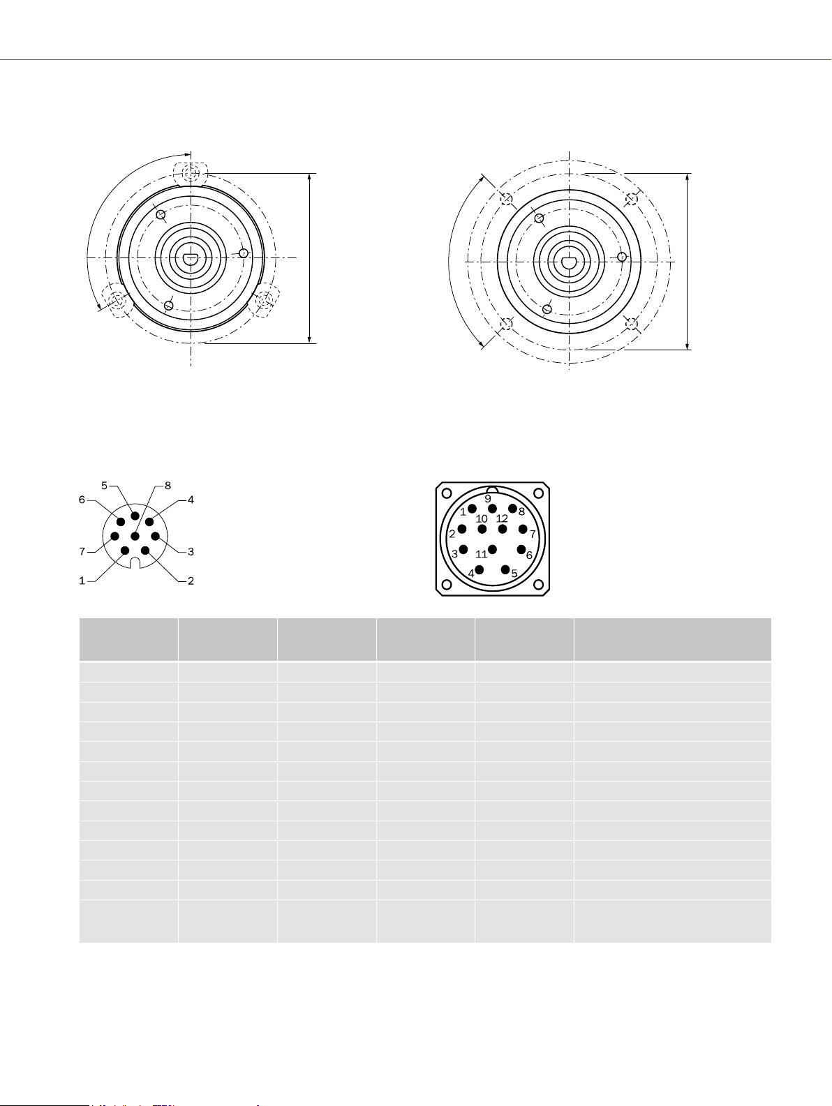
PIN assignment
Cable, 8-wire
View of M12 male device connector on encoder
PIN, 8-pin, M12
male connector
PIN, 12-pin, M23
male connector
Color of the wires
for encoders with
TTL/HTL signal Sin/cos 1.0 V
cable outlet
1 6 Brown ¯A COS– Signal wire
2 5 White A COS+ Signal wire
3 1 Black ¯B SIN– Signal wire
4 8 Pink B SIN+ Signal wire
5 4 Yellow ¯Z ¯Z Signal wire
6 3 Violet Z Z Signal wire
7 10 Blue GND GND Ground connection of the encoder
8 12 Red +U
– 9 – n.c. n.c. Not assigned
– 2 – n.c. n.c. Not assigned
– 11 – n.c. n.c. Not assigned
– 7
Screen Screen Screen Screen Screen
1)
For electrical interfaces only: M, U, V, W with 0-SET function on PIN 7 on M23 male connector. The 0-SET input is used to set the zero pulse on the current shaft posi-
tion. If the 0-SET input is connected to US for longer than 250 ms after it had previously been unassigned for at least 1,000 ms or had been connected to the GND, the
current position of the shaft is assigned to the zero pulse signal “Z”.
1)
– 0-SET
S
View of M23 male device connector on encoder
Explanation
SS
+U
S
1)
n.c. Set zero pulse
Supply voltage (volt-free to housing)
Screen connected to housing on encoder side.
Connected to ground on control side.
1)
F-182
ENCODERS | SICK 8015560/2015-09-01
Subject to change without notice

Interfaces
A
B
Z1
Z2
Z3
Z4
90° el.
A
B
Z
1 turn
Signal outputs for electrical interfaces TTL and HTL
INCREMENTAL ENCODERS DFS60
Measuring step
CW with view on the encoder shaft in direction “A”, compare
dimensional drawing.
Electrical zero pulse width 90°, 180° or 270°,
programmable Width of the zero pulse in relation to
a pulse period.
Measuring step
360° el.
Supply voltage Output
4.5 ... 5.5 V TTL
10 ... 32 V TTL
10 ... 32 V HTL
Mechanical zero pulse width 1° to 359°, programmable Width of the zero pulse in relation to a
mechanical revolution of the shaft.
F
360° mech.
90°
el. gated with
channel A and B
180°
el. gated with
channel B
180°
el. gated with
channel A
270°
el. gated with
channel A or B
CW with view on the encoder shaft in direction “A,” compare
dimensional drawing.
Supply voltage Output
√
4.5 ... 32 V HTL/TTL programmable
Subject to change without notice
1°–359°
Ω
ENCODERS | SICK8015560/2015-09-01
F-183

DFS60 INCREMENTAL ENCODERS
1.75
1.75 V
V
360° el.
COS+ – COS–
SIN+ – SIN–
Z –
V
360° el.
Electrical interfaces sin/cos 1.0 V
SS
Supply voltage Output
4.5 ... 5.5 V Sin/cos 1.0 V
SS
Signals before difference at 120 Ω load and US = 5 V
Signal diagram for clockwise shaft rotation, looking in direction “A” (shaft)
2.5 V
2.5 V
2.9 V
2.9 V
90° el.
COS+ COS–
SIN+ SIN–
V
Z
¯Z
0.5 V
0.5
F
Interface signals Sin+, SIN–, COS+, COS– Signals before difference at 120 Ω load Signal offset
Differential analog 0.5 VSS ± 20% 2.5 V ± 10%
Interface signals Z, Z Signals before difference at 120 Ω load
Digital, differential Low: 1.75 V ± 15%; High: 2.9 V ± 15%
Signals after difference at 120 Ω load and US = 5 V
Signal diagram for clockwise shaft rotation, looking in direction “A” (shaft)
0 V
90° el.
0 V
¯Z
0 V
1 V
1 V
2.3
F-184
ENCODERS | SICK 8015560/2015-09-01
Subject to change without notice

INCREMENTAL ENCODERS DFS60
Recommended accessories
Mounting systems
Mounting brackets and plates
Mounting bracket
Figure Brief description Type Part no.
Mounting bracket for encoder with centering hub 36 mm, including mounting kit for face
mount ange
BEF-WF-36 2029164
Flanges
Flange plate
Figure Brief description Type Part no.
Standard two-sided stator coupling, with screw hole circle diameter 63 mm, slot width
3.2 mm, 10.4 mm high
One-sided stator coupling, slot, slot radius 33 mm – 48.5 mm, slot width 5.1 mm BEF-DS01DFS/VFS 2047428
One-sided stator coupling, slot, slot radius 32.25 mm – 141.75 mm, slot width 5.1 mm BEF-DS02DFS/VFS 2047430
One-sided stator coupling, slot, slot radius 33 mm – 211.9 mm, slot width 5.1 mm BEF-DS03DFS/VFS 2047431
Two-sided stator coupling, with screw hole circle diameter 72 mm, slot width 3.2 mm,
16.5 mm high
Two-sided stator coupling, with screw hole circle diameter 72 mm, slot width 3.2 mm,
10.4 mm high
BEF-DS00XFX 2056812
BEF-DS05XFX 2057423
BEF-DS07XFX 2059368
F
Flange adapter, adaptation of face mount ange with 36 mm centering hub to 50 mm
servo ange, aluminum, including 3 at head screws M4 x 10
Flange adapter, adaptation of face mount ange with 36 mm centering hub to 60 mm
square mounting plate, aluminum, including 3 at head screws M4 x 10
Flange adapter, adaptation of face mount ange with 36 mm centering hub to 58 mm
square mounting plate with shock absorbers, aluminum
Flange adapter, adaptation of face mount ange with 36 mm centering hub to 63 mm
square mounting plate, aluminum, including 3 at head screws M4 x 10
Flange adapter, adaptation of face mount ange with 36 mm centering hub to 100 mm
servo ange with 60 mm centering hub, aluminum
BEF-FA-036-050 2029160
BEF-FA-036-060REC 2029162
BEF-FA-036-060RSA 2029163
BEF-FA-036-063REC 2034225
BEF-FA-036-100 2029161
Subject to change without notice
ENCODERS | SICK8015560/2015-09-01
F-185

DFS60 INCREMENTAL ENCODERS
Other mounting accessories
Measuring wheels and measuring wheel systems
Figure Brief description Type Part no.
F
Measuring wheel with smooth plastic surface (Hytrel) for 10 mm solid shaft, circumference 200 mm
Measuring wheel with ridged plastic surface (Hytrel) for 10 mm solid shaft, circumference 200 mm
Measuring wheel with smooth plastic surface (Hytrel) for 10 mm solid shaft, circumference 500 mm
Measuring wheel with O-ring (NBR70) for 6 mm solid shaft, circumference 200 mm BEF-MR006020R 2055222
Measuring wheel with O-ring (NBR70) for 6 mm solid shaft, circumference 300 mm BEF-MR006030R 2055634
Measuring wheel with O-ring (NBR70) for 6 mm solid shaft, circumference 500 mm BEF-MR006050R 2055225
Measuring wheel with O-ring (NBR70) for 10 mm solid shaft, circumference 200 mm BEF-MR010020R 2055224
Measuring wheel with O-ring (NBR70) for 10 mm solid shaft, circumference 300 mm BEF-MR010030R 2049278
Measuring wheel with O-ring (NBR70) for 10 mm solid shaft, circumference 500 mm BEF-MR010050R 2055227
O-ring for measuring wheels (circumference 200 mm) BEF-OR-053-040 2064061
O-ring for measuring wheels (circumference 300 mm) BEF-OR-083-050 2064076
O-ring for measuring wheels (circumference 500 mm) BEF-OR-145-050 2064074
BEF-MR-010020 5312988
BEF-MR-010020G 5318678
BEF-MR-010050 5312989
Modular measuring wheel system
Brief description Type Part no.
Measuring wheel system, desired mounting position: left, for DBS60-S4, DFS60-S4, AFS60-S4, and
AFM60-S4
Measuring wheel system, desired mounting position: right, for DBS60-S4, DFS60-S4, AFS60-S4, and
AFM60-S4
BEF-MRS-10-1 2071958
BEF-MRS-10-2 2071957
Mounting bell
Figure Brief description Type Part no.
Mounting bell for encoders with a servo ange, centering hub 50 mm, including mounting kit
BEF-MG-50 5312987
Servo clamps
Figure Brief description Type Part no.
Half-shell servo clamps (2 pcs.) for servo anges with a 50 mm centering hub BEF-WG-SF050 2029165
Servo clamps, large, for servo anges (clamps, eccentric fastener), 3 pcs., without
mounting material
BEF-WK-SF 2029166
F-186
ENCODERS | SICK 8015560/2015-09-01
Subject to change without notice

INCREMENTAL ENCODERS DFS60
Miscellaneous
Figure Brief description Type Part no.
Clamping ring for metal hollow shaft, metal BEF-KR-M 2064709
Bearing block for hollow shaft encoder, including xing screws BEF-FA-B12-010 2042728
Bearing block for servo and face mount ange encoder BEF-FA-LB1210 2044591
Mounting kit for servo ange encoder on the bearing block, 1 bar coupling SKPS
1520 06/06 1 hexagon socket wrench SW1.5 DIN 911, 3 mounting eccentric BEMN
1242 49 3 screws M4 x 10 DIN 912,1 hexagon socket wrench SW3 DIN 911
Shaft adaptation
Collets and clamping rings
Figure Brief description Type Part no.
PEEK conductor insulation (shaft diameter 8 mm, outer diameter 10 mm)
PEEK conductor insulation (shaft diameter 10 mm, outer diameter 12 mm)
PEEK conductor insulation (shaft diameter 11 mm, outer diameter 12.7 mm)
PEEK conductor insulation (shaft diameter 12 mm, outer diameter 14 mm)
PEEK conductor insulation (shaft diameter 1/2"(12.7 mm), outer diameter 15 mm)
Metal collet for hollow shaft, shaft diameter 8 mm, outer diameter 5/8" (15.875 mm),
metal
Metal collet for hollow shaft, shaft diameter 3/8 " (9.525 mm), outer diameter 5/8"
(15.875 mm), metal
Metal collet for hollow shaft, shaft diameter 10 mm, outer diameter 5/8" (15.875 mm),
metal
Metal collet for hollow shaft, shaft diameter 12 mm, outer diameter 5/8" (15.875 mm),
metal
Metal collet for hollow shaft, shaft diameter 1/2" (12.7 mm), outer diameter 5/8"
(15.875 mm), metal
Metal collet for hollow shaft, shaft diameter 14 mm, outer diameter 5/8" (15.875 mm),
metal
BEF-MK-LB 5320872
PEEK CONDUCTOR
INSULATION
PEEK CONDUCTOR
INSULATION
PEEK CONDUCTOR
INSULATION
PEEK CONDUCTOR
INSULATION
PEEK CONDUCTOR
INSULATION
SPZ-58Z-008-M 2076219
SPZ-58Z-38Z-M 2076224
SPZ-58Z-010-M 2076220
SPZ-58Z-012-M 2076221
SPZ-58Z-12Z-M 2076225
SPZ-58Z-014-M 2076222
2065642
2064571
2077319
2064573
2064572
F
Metal collet for hollow shaft, shaft diameter 15 mm, outer diameter 5/8" (15.875 mm),
metal
Plastic isolated collet for hollow shaft, shaft diameter 6 mm, outer diameter 5/8"
(15.875 mm), plastic
Plastic isolated collet for hollow shaft, shaft diameter 8 mm, outer diameter 5/8"
(15.875 mm), plastic
Plastic isolated collet for hollow shaft, shaft diameter 3/8" (9.525 mm), outer diameter
5/8" (15.875 mm), plastic
Plastic isolated collet for hollow shaft, shaft diameter 10 mm, outer diameter 5/8"
(15.875 mm), plastic
Plastic isolated collet for hollow shaft, shaft diameter 12 mm, outer diameter 5/8"
(15.875 mm), plastic
Plastic isolated collet for hollow shaft, shaft diameter 1/2" (12.7 mm), outer diameter
5/8" (15.875 mm), plastic
Plastic isolated collet for hollow shaft, shaft diameter 14 mm, outer diameter 5/8"
(15.875 mm), plastic
Plastic isolated collet for hollow shaft, shaft diameter 15 mm, outer diameter 5/8"
(15.875 mm), plastic
Subject to change without notice
SPZ-58Z-015-M 2076223
SPZ-58Z-006-P 2076228
SPZ-58Z-008-P 2076229
SPZ-58Z-38Z-P 2076226
SPZ-58Z-010-P 2076230
SPZ-58Z-012-P 2076231
SPZ-58Z-12Z-P 2076227
SPZ-58Z-014-P 2076232
SPZ-58Z-015-P 2076233
ENCODERS | SICK8015560/2015-09-01
F-187

F
DFS60 INCREMENTAL ENCODERS
Shaft couplings
Figure Brief description Type Part no.
Bellows coupling, shaft diameter 6 mm / 6 mm, maximum shaft offset: radial
± 0.25 mm, axial ± 0.4 mm, angular +/- 4°; max. speed 10,000 rpm, –30 °C to
+120 °C, max. torque 80 Ncm; material: stainless steel bellows, aluminum hub
Bellows coupling, shaft diameter 6 mm / 10 mm, maximum shaft offset: radial
± 0.25 mm, axial ± 0.4 mm, angular +/- 4°; max. speed 10,000 rpm, –30 °C to
+120 °C, max. torque 80 Ncm; material: stainless steel bellows, aluminum hub
Bellows coupling, shaft diameter 10 mm / 10 mm, maximum shaft offset: radial
± 0.25 mm, axial ± 0.4 mm, angular +/- 4°; max. speed 10,000 rpm, –30 °C to
+120 °C, max. torque 80 Ncm; material: stainless steel bellows, aluminum hub
Bellows coupling, shaft diameter 10 mm/12 mm; maximum shaft offset: radial +/-
0.25 mm, axial +/- 0.4 mm, angular +/- 4°; max. revolutions 10,000 rpm,
–30 ° to +120 °C, max. torque 80 Ncm; material: stainless steel bellows, aluminum
clamping hubs
Bar coupling, shaft diameter 6 mm / 6 mm, maximum shaft offset: radial ± 0.3 mm,
axial ± 0.2 mm, angle ± 3°; max. speed 10,000 rpm, –10 °C to +80 °C, max. torque
80 Ncm; material: ber-glass reinforced polyamide, aluminum hub
Bar coupling, shaft diameter 6 mm / 8 mm, maximum shaft offset radial ± 0.3 mm, ax-
ial ± 0.2 mm, angle ± 3°; max. speed 10,000 rpm, torsion spring rigidity 38 Nm/wheel;
material: ber-glass reinforced polyamide, aluminum hub
Bar coupling, shaft diameter 6 mm/10 mm, maximum shaft offset: radial ± 0.3 mm,
axial ± 0.2 mm, angular ± 3°; max. speed 10,000 rpm, –10 °C to +80 °C, max. torque
80 Ncm; material: ber-glass reinforced polyamide, aluminum hub
Bar coupling, shaft diameter 8 mm / 10 mm, maximum shaft offset: radial ± 0.3 mm,
axial ± 0.2 mm, angular ± 3°; torsion spring rigidity 38 Nm/wheel; material: ber-glass
reinforced polyamide, aluminum hub
Bar coupling, shaft diameter 10 mm / 10 mm, maximum shaft offset radial ± 0.3 mm,
axial ± 0.2 mm, angle ± 3°; max. speed 10,000 rpm, torsion spring rigidity 38 Nm/
wheel; material: ber-glass reinforced polyamide, aluminum hub
Spring washer coupling, shaft diameter 6 mm/10 mm, maximum shaft offset: radial
± 0.3 mm, axial ± 0.4 mm, angular ± 2.5°; max. speed 12,000 rpm, –10 °C to +80 °C,
max. torque 60 Ncm; material: aluminum ange, ber-glass reinforced polyamide mem-
brane and tempered steel coupling pin
Spring washer coupling, shaft diameter 10 mm / 10 mm, maximum shaft offset: radial
± 0.3 mm, axial ± 0.4 mm, angular ± 2.5°; max. speed 12,000 rpm, –10° to +80° Celsius, max. torque 60 Ncm; material: aluminum ange, glass ber-reinforced polyamide
membrane and hardened steel coupling pin
Double-loop coupling, shaft diameter 6 mm/10 mm, maximum shaft offset: radial
± 2.5 mm, axial ± 3 mm, angular ± 10°; max. speed 3,000 rpm, –30 °C to +80 °C,
max. torque 1.5 Nm; material: polyurethane, galvanized steel ange
Double-loop coupling, shaft diameter 8 mm/10 mm, maximum shaft offset: radial
± 2.5 mm, axial ± 3 mm, angular ± 10°; max. speed 3,000 rpm, –30 °C to +80 °C,
max. torque 1.5 Nm; material: polyurethane, galvanized steel ange
Double-loop coupling, shaft diameter 10 mm/10 mm, maximum shaft offset: radial
± 2.5 mm, axial ± 3 mm, angular ± 10°; max. speed 3,000 rpm, –30 °C to +80 °C,
max. torque 1.5 Nm; material: polyurethane, galvanized steel ange
Double-loop coupling, shaft diameter 10 mm/12 mm, maximum shaft offset: radial
± 2.5 mm, axial ± 3 mm, angular ± 10°; max. speed 3,000 rpm, –30 °C to +80 °C,
max. torque 1.5 Nm; material: polyurethane, galvanized steel ange
KUP-0606-B 5312981
KUP-0610-B 5312982
KUP-1010-B 5312983
KUP-1012-B 5312984
KUP-0606-S 2056406
KUP-0608-S 5314179
KUP-0610-S 2056407
KUP-0810-S 5314178
KUP-1010-S 2056408
KUP-0610-F 5312985
KUP-1010-F 5312986
KUP-0610-D 5326697
KUP-0810-D 5326704
KUP-1010-D 5326703
KUP-1012-D 5326702
F-188
ENCODERS | SICK 8015560/2015-09-01
Subject to change without notice

Connectivity
Plug connectors and cables
Connecting cables with female connector
INCREMENTAL ENCODERS DFS60
Figure Brief description
Head A: female connector, JST, 8-pin, straight
Head B: cable
Cable: incremental, suitable for drag chain, PUR, halogen-free, shielded,
4 x 2 x 0.15 mm², Ø 5.6 mm
Head A: female connector, M12, 8-pin, straight
Head B: cable
Cable: suitable for drag chain, PVC, shielded, 4 x 2 x 0.25 mm², Ø 7.0 mm
Head A: female connector, M23, 12-pin, straight
Head B: cable
Cable: incremental, PUR, shielded, 4 x 2 x 0.25 mm² + 2 x 0.5 mm²
+ 1 x 0.14
Head A: female connector, M23, 12-pin, straight
Head B: cable
Cable: incremental, suitable for drag chain, PUR, shielded, 4 x 2 x 0.25 mm²
+ 2 x 0.5
Head A: female connector, M23, 12-pin, straight
Head B: cable
Cable: incremental, PUR, shielded, 4 x 2 x 0.25 mm² + 2 x 0.5 mm²
+ 1 x 0.14
Head A: female connector, M23, 12-pin, straight
Head B: cable
Cable: incremental, suitable for drag chain, PUR, shielded, 4 x 2 x 0.25 mm²
+ 2 x 0.5
1)
Warning! Only in combination with electrical interfaces A, C, E and P.
2)
Warning! Only in combination with electrical interfaces U, V, W and M.
mm², Ø 7.8 mm
mm² + 1 x 0.14 mm², Ø 7.8 mm
mm², Ø 7.8 mm
mm² + 1 x 0.14 mm², Ø 7.8 mm
1)
2)
Length
Type Part no.
of
cable
0.5 m DOL-0J08-G0M5AA3
1.5 m DOL-0J08-G1M5AA3
3 m DOL-0J08-G03MAA3
5 m DOL-0J08-G05MAA3
10 m DOL-0J08-G10MAA3
2 m DOL-1208-G02MAC1 6032866
5 m DOL-1208-G05MAC1 6032867
10 m DOL-1208-G10MAC1 6032868
20 m DOL-1208-G20MAC1 6032869
2 m DOL-2312-G02MLA3
7 m DOL-2312-G07MLA3
10 m DOL-2312-G10MLA3
15 m DOL-2312-G15MLA3
20 m DOL-2312-G20MLA3
25 m DOL-2312-G25MLA3
30 m DOL-2312-G30MLA3
1.5 m DOL-2312-G1M5MA3 2029212
3 m DOL-2312-G03MMA3
5 m DOL-2312-G05MMA3
1)
2)
10 m DOL-2312-G10MMA3
20 m DOL-2312-G20MMA3
30 m DOL-2312-G30MMA3
2 m DOL-2312-G02MLD1
7 m DOL-2312-G07MLD1
10 m DOL-2312-G10MLD1
15 m DOL-2312-G15MLD1
20 m DOL-2312-G20MLD1
25 m DOL-2312-G25MLD1
30 m DOL-2312-G30MLD1
1.5 m DOL-2312-G1M5MD1 2062240
3 m DOL-2312-G03MMD1
5 m DOL-2312-G05MMD1
10 m DOL-2312-G10MMD1
20 m DOL-2312-G20MMD1
30 m DOL-2312-G30MMD1
2046873
2046874
2046875
2046876
2046877
2030682
2030685
2030688
2030692
2030695
2030699
2030702
2029213
2029214
2029215
2029216
2029217
2062202
2062203
2062204
2062205
2062206
2062207
2062208
2062243
2062244
2062245
2062246
2062247
F
Subject to change without notice
ENCODERS | SICK8015560/2015-09-01
F-189

DFS60 INCREMENTAL ENCODERS
Female connector (ready to assemble)
Figure Brief description Type Part no.
Head A: female connector, M12, 8-pin, straight, A encoded, shielded, for cable diameter
4 mm ... 8 mm
Head B: -
Operating temperature: –40 °C ... +85 °C
Head A: female connector, M23, 12-pin, straight, shielded, for cable diameter
5.5
mm ... 10.5 mm
Head B: Operating temperature:
–20
°C ... +130 °C
Head A: female connector, M23, 12-pin, angled, shielded, for cable diameter
mm ... 6.6 mm
4.2
Head B: Operating temperature:
–20
°C ... +130 °C
Head A: female connector, M23, 12-pin, straight, shielded, for cable diameter
mm ... 10.5 mm
5.5
Head B: Operating temperature:
–40
°C ... +125 °C
Cables (ready to assemble)
DOS-1208-GA01
DOS-2312-G
DOS-2312-W01
DOS-2312-G02
6045001
6027538
2072580
2077057
F
Figure Brief description Length
Type Part no.
of
cable
Head A: cable
Head B: cable
Cable: suitable for drag chain, PUR, halogen-free, shielded, 4 x 2 x 0.15 mm²,
Ø 5.6 mm
Head A: cable
Head B: cable
Cable: PUR, shielded, 4 x 2 x 0.25 mm² + 2 x 0.5 mm² + 1 x 0.14 mm²,
Ø 7.5 mm
Head A: cable
Head B: cable
Cable: suitable for drag chain, PUR, halogen-free, shielded, 4 x 2 x 0.25 mm²
+ 2 x 0.5 mm² + 2 x 0.14 mm², Ø 7.8 mm
Head A: cable
Head B: cable
Cable: suitable for drag chain, PUR, halogen-free,
shielded, UV and saltwater resistant, 4 x 2 x 0.25 mm² + 2 x 0.5 mm²
+ 2 x 0.14 mm², Ø 7.8 mm
By the
meter
LTG-2308-MWENC 6027529
LTG-2411-MW 6027530
LTG-2512-MW 6027531
LTG-2612-MW 6028516
Male connector (ready to assemble)
Figure Brief description Type Part no.
Head A: male connector, M12, 8-pin, straight, A encoded, shielded, for cable diameter
4 mm ... 8 mm
Head B: Operating temperature:
–40 °C ... +85 °C
Head A: male connector, M23, 12-pin, straight, shielded, for cable diameter
5.5 mm ... 10.5 mm
Head B:
Operating temperature: –20 °C ... +130 °C
Head A: male connector, M23, 12-pin, straight, for cable diameter 5.5 mm ... 10.5 mm
Head B: Operating temperature:
–40 °C ... +125 °C
STE-1208-GA01 6044892
STE-2312-G 6027537
STE-2312-G01 2077273
F-190
ENCODERS | SICK 8015560/2015-09-01
Subject to change without notice

Connection cables with female and male connector
INCREMENTAL ENCODERS DFS60
Figure Brief description Length
of
cable
Head A: female connector, JST, 8-pin, straight
Head B: male connector, M23, 12-pin, straight
Cable: suitable for drag chain, PUR, halogen-free, shielded, 4 x 2 x 0.15 mm²,
Ø 5.6 mm
Head A: female connector, connector system, 8-pin, straight
Head B: male connector, D-Sub, 9-pin, straight
Cable: PVC, shielded, can be used for encoders with cable outlet in conjunction with PGT-10-Pro
Head A: female connector, M12, 8-pin, straight
Head B: male connector, D-Sub, 9-pin, straight
Cable: shielded, 4 x 2 x 0.08 mm²
Head A: female connector, M23, 12-pin, straight
Head B: male connector, D-Sub, 9-pin, straight
Cable: shielded, 4 x 2 x 0.08 mm²
0.35 m STL-2312-GM35AA3 2061621
1 m STL-2312-G01MAA3 2061622
2 m STL-2312-G02MAA3 2061504
0.5 m DSL-0D08-G0M5AC3 2061739
0.5 m DSL-2D08-G0M5AC3 2046579
0.5 m DSL-3D08-G0M5AC3 2046580
Type Part no.
Other accessories
Programming and conguration tools
Figure Brief description Type Part no.
Programming unit USB, for programmable SICK Encoders AFS60, AFM60, DFS60,
VFS60, DFV60 and wire draw encoders with programmable encoder.
Programming unit display for programmable SICK DFS60, VFS60, DFV60, AFS/AFM60,
AHS/AHM36 encoders, and wire draw encoders with DFS60, AFS/AFM60, and AHS/
AHM36. Compact dimensions, low weight, and intuitive operation.
- For additional accessories, please see page K-668 onwards
PGT-08-S 1036616
PGT-10-Pro 1072254
F
Subject to change without notice
ENCODERS | SICK8015560/2015-09-01
F-191
 Loading...