

Page 1
deTem4 Core Ex
Multiple light beam safety device
O P E R A T I N G I N S T R U C T I O N S
Page 2

Described product
deT
em4 Core Ex
Manufacturer
SICK AG
Erwin-Sick-Str. 1
79183 Waldkirch
Germany
Legal information
his work is protected by copyright. Any rights derived from the copyright shall be
T
reserved for SICK AG. Reproduction of this document or parts of this document is only
permissible within the limits of the legal determination of Copyright Law. Any modifica‐
tion, abridgment or translation of this document is prohibited without the express writ‐
ten permission of SICK AG.
The trademarks stated in this document are the property of their respective owner.
© SICK AG. All rights reserved.
Original document
T
his document is an original document of SICK AG.
2
O PE R AT I NG IN S TR U CT I ON S | deTem4 Core Ex 8022875/2019-03-04 | SICK
Subject to change without notice
Page 3

Contents
CONTENTS
1 About this document........................................................................ 6
1.1 Function of this document....................................................................... 6
1.2 Scope......................................................................................................... 6
1.3 Target groups and structure of these operating instructions................ 6
1.4 Additional information.............................................................................. 7
1.5 Symbols and document conventions...................................................... 7
2 Safety information............................................................................ 9
2.1 General safety notes................................................................................ 9
2.2 Intended use............................................................................................. 9
2.3 Requirements for the qualification of personnel.................................... 11
3 Product description........................................................................... 13
3.1 Setup and function................................................................................... 13
3.2 Product characteristics............................................................................ 14
3.2.1 Status indicators...................................................................... 14
3.3 Example applications............................................................................... 16
4 Project planning................................................................................ 17
4.1 Manufacturer of the machine.................................................................. 17
4.2 Operating entity of the machine.............................................................. 17
4.3 Design........................................................................................................ 17
4.3.1 Scanning range and beam separation................................... 18
4.3.2 Minimum distance from the hazardous point....................... 18
4.3.3 Minimum distance from reflective surfaces.......................... 20
4.3.4 Protection against interference from systems in close prox‐
y to each other................................................................... 22
imit
4.4 Integrating into the electrical control....................................................... 22
4.4.1 Restart interlock...................................................................... 25
4.4.2 External device monitoring (EDM).......................................... 25
4.4.3 Connection diagrams.............................................................. 26
4.5 Testing plan............................................................................................... 26
4.5.1 Test rod check.......................................................................... 27
4.5.2 Visual check of the machine and the protective device........ 28
5 Mounting............................................................................................. 29
5.1 Safety......................................................................................................... 29
5.2 Unpacking.................................................................................................. 30
5.3 Mounting................................................................................................... 30
5.3.1 Mount the multiple light beam safety device in the explo‐
sion-proof enclosure (only if being used in North America).. 32
5.3.2 Mount the optional cable gland.............................................. 34
5.3.3 Mount the handles to the cover of the explosion-proof
enclosure.................................................................................. 34
5.3.4 Mount the multiple light beam safety device........................ 35
8022875/2019-03-04 | SICK O PE R AT I NG IN S TR U CT I ON S | deTem4 Core Ex
Subject to change without notice
3
Page 4

CONTENTS
6 Electrical installation........................................................................ 42
6.1 Safety......................................................................................................... 42
6.2 System connection (M12, 5-pin)............................................................. 44
6.3 System connection via connection cable (M12, 5-pin to 8-pin)............ 45
7 Commissioning.................................................................................. 46
7.1 Safety......................................................................................................... 46
7.2 Overview.................................................................................................... 46
7.3 Switching on.............................................................................................. 47
7.4 Sender and receiver alignment................................................................ 47
7.4.1 Aligning the sender and receiver............................................ 47
7.4.2 Aligning the sender, receiver, and deflector mirror................ 48
7.4.3 Alignment with the alignment bracket................................... 49
7.4.4 Indication of the alignment quality......................................... 50
7.5 Check during commissioning and modifications.................................... 51
8 Operation............................................................................................ 52
8.1 Safety......................................................................................................... 52
8.2 Regular thorough check........................................................................... 52
9 Maintenance...................................................................................... 53
9.1 Safety......................................................................................................... 53
9.2 Regular cleaning....................................................................................... 53
9.3 Regular thorough check........................................................................... 55
10 Troubleshooting................................................................................. 56
10.1 Safety......................................................................................................... 56
10.2 Diagnostic LEDs........................................................................................ 56
10.2.1 Fault indicators........................................................................ 56
11 Decommissioning............................................................................. 59
11.1 Protection of the environment................................................................. 59
11.2 Disposal..................................................................................................... 59
12 Technical data.................................................................................... 60
12.1 Data sheet................................................................................................. 60
12.2 Table of weights........................................................................................ 62
12.3 Dimensional drawings.............................................................................. 63
13 Ordering information........................................................................ 66
13.1 Scope of delivery....................................................................................... 66
13.2 Ordering information deTem4 Core Ex.................................................... 66
14 Accessories........................................................................................ 67
14.1 Brackets.................................................................................................... 67
14.2 Mounting accessories.............................................................................. 68
14.3 Connectivity............................................................................................... 68
4
O PE R AT I NG IN S TR U CT I ON S | deTem4 Core Ex 8022875/2019-03-04 | SICK
Subject to change without notice
Page 5

CONTENTS
14.4 Alignment aid............................................................................................ 68
14.5 Deflector mirrors....................................................................................... 69
14.5.1 Function and use..................................................................... 69
14.5.2 Change in scanning range using deflector mirrors................ 69
14.5.3 Deflector mirror – ordering information................................. 69
14.5.4 Deflector mirror PNS75 - ordering information...................... 69
14.5.5 Deflector mirror PNS125 - ordering information................... 69
14.6 Test rods.................................................................................................... 70
15 Annex.................................................................................................. 71
15.1 Compliance with EU directives................................................................. 71
15.2 Note on specified standards.................................................................... 72
15.3 Checklist for initial commissioning and commissioning........................ 73
16 List of figures..................................................................................... 74
17 List of tables....................................................................................... 75
8022875/2019-03-04 | SICK O PE R AT I NG IN S TR U CT I ON S | deTem4 Core Ex
Subject to change without notice
5
Page 6
BOUT THIS DOCUMENT
1 A
1 About this document
1.1 Function of this document
These operating instructions contain the information needed during the life cycle of the
iple light beam safety device.
mult
Operating instructions of the multiple light beam safety device must be made available
to all people who work with the device.
Please read these operating instructions carefully and make sure that you understand
the content fully before working with the multiple light beam safety device.
1.2 Scope
These operating instructions only apply to the deTem4 Core Ex multiple light beam
s
afety device with the following type label entry in the Operating Instructions field:
8022833
•
This document is included with the following SICK part numbers (this document in all
available language versions):
8022833
•
1.3 Target groups and structure of these operating instructions
These operating instructions are intended for the following target groups: project devel‐
oper
s (planners, developers, designers), installers, electricians, safety experts (such as
CE authorized representatives, compliance officers, people who test and approve the
application), operators, and maintenance personnel.
The structure of these operating instructions is based on the life cycle phases of the
multiple light beam safety device: project planning, mounting, electrical installation,
commissioning, operation, and maintenance.
In many applications, therefore, the target groups consist of the manufacturer and the
operating entity of the machine in which the multiple light beam safety device is inte‐
grated:
Area of responsibility Target group Special chapters of these operating instruc‐
Manufacturer Project developers
(planners, developers,
designers)
Installers Mounting, pa
Electricians Electrical installation, page 42
Safety experts Project planning, pa
Operating entity Operators Operation, pa
Maintenance person‐
l
ne
1
Chapters not listed here are intended for all target groups. All target groups must understand the safety
no
tes in all of the operating instructions!
1
t
ions
Project planning, page 17
Technical data, page 60
Accessories, page 67
Commissioning, page 46
Technical data, page 60
Checklist for initial commissioning and com‐
missioning, page 73
Troubleshooting, page 56
Maintenance, page 53
Troubleshooting, page 56
Ordering information, page 66
ge 29
ge 17
ge 52
6
O PE R AT I NG IN S TR U CT I ON S | deTem4 Core Ex 8022875/2019-03-04 | SICK
Subject to change without notice
Page 7
In other applications, the operating organization is also the manufacturer of the equip‐
ment w
ith the corresponding allocation of the target groups.
1.4 Additional information
www.sick.com
T
he following information is available on the Internet:
This document in other languages
•
Data sheets and application examples
•
CAD data and dimensional drawings
•
Certificates (e.g. EU declaration of conformity)
•
Guide for Safe Machinery Six steps to a safe machine
•
1.5 Symbols and document conventions
The following symbols and conventions are used in this document:
Safety notes and other notes
DANGER
Indic
ates a situation presenting imminent danger, which will lead to death or serious
injuries if not prevented.
ABOUT THIS DOCUMENT 1
WARNING
Indicates a situation presenting possible danger, which may lead to death or serious
injuries if not prevented.
CAUTION
ates a situation presenting possible danger, which may lead to moderate or minor
Indic
injuries if not prevented.
NOTICE
Indic
ates a situation presenting possible danger, which may lead to property damage if
not prevented.
NOTE
Indic
ates useful tips and recommendations.
Instructions to action
he arrow denotes instructions to action.
T
b
1. The sequence of instructions for action is numbered.
2. Follow the order in which the numbered instructions are given.
✓
The check mark denotes the result of an instruction.
LED symbols
These symbols indicate the status of an LED:
The LED is off.
o
The LED is flashing.
Ö
The LED is illuminated continuously.
O
8022875/2019-03-04 | SICK O PE R AT I NG IN S TR U CT I ON S | deTem4 Core Ex
Subject to change without notice
7
Page 8

1 A
BOUT THIS DOCUMENT
Sender and receiver
T
hese symbols indicate the sender and receiver of the device:
The symbol indicates the sender.
s
The symbol indicates the receiver.
r
8
O PE R AT I NG IN S TR U CT I ON S | deTem4 Core Ex 8022875/2019-03-04 | SICK
Subject to change without notice
Page 9
2 Safety information
2.1 General safety notes
DANGER
H
azard due to lack of effectiveness of the protective device
In the case of non-compliance, it is possible that the dangerous state of the machine
may not be stopped or not stopped in a timely manner.
Please read this document carefully and make sure that you understand the con‐
b
tent fully before working with the device.
Follow all safety notes in this document.
b
WARNING
Risk of ineffectiveness of the protective device
Please observe the following information to ensure safe and correct use of the device
deTem4 Core Ex.
National and international regulations and guidelines must be observed when
b
mounting, using, and commissioning electrical devices as well as when carrying
out regular technical inspections in explosion-hazardous areas. Article 500 of the
National Electrical Code and ATEX Directive 2014/34/EU shall apply in particular.
Manufacturers of and entities operating machines using the device are responsi‐
ble for ensuring that all applicable safety regulations and guidelines are complied
with.
These operating instructions must be made available to the operator of the
b
machine on which the device is used. Qualified safety personnel must instruct the
operator in how to use the device. The operator must also be directed to read and
follow the operating instructions.
SAFETY INFORMATION 2
DANGER
Ris
Failure to observe this instruction can result in a risk of ignition from potential sparking.
b
NOTE
SIC
•
•
2.2 Intended use
Overview
T
device (ESPE) and is suitable for the following applications:
•
•
The multiple beam light beam safety device deTem4 Core Ex is suitable for use in
enc
defined in the National Electrical Code® and Canadian Electrical Code®:
k of ignition
Ensure that only accessories that are approved for explosion-hazardous areas are
used.
K provides more information about the following explosion-proof connections:
Joint between glass and cover
Joint between cover and explosion-proof enclosure
he deTem4 Core Ex multiple light beam safety device is an electro-sensitive protective
Single-sided access protection
Multi-sided access protection
losed spaces only. It has UL/cUL certification for the following hazardous areas
8022875/2019-03-04 | SICK O PE R AT I NG IN S TR U CT I ON S | deTem4 Core Ex
Subject to change without notice
9
Page 10
2 SAFETY INFORMATION
•
•
•
The multiple light beam safety device deTem4 Core Ex also complies with these stan‐
ards: EN 60079-0:2012/A11:2013/IEC 60079-0 Edition 6.0, EN 60079-1:2014/IEC
d
60079-1 Edition 7.0, EN 60079-31:2014/IEC 60079-31 Edition 2.0 and is certified for
the following hazardous areas:
•
•
•
•
DEMKO 14 ATEX 1315X
IECEx UL 14.0034X
The multiple light beam safety device deTem4 Core Ex does not emit any paint wetting
im
rials into the surrounding area.
The deTem4 Core Ex multiple light beam safety device must only be used within the lim‐
its of the prescribed and specified technical data and operating conditions at all times.
ss I, Groups C, D
Cla
Class II, Groups E, F, G
Class III
X II 2 G Ex db IIB T6
X II 2 D Ex tb IIIC T56 °C Db IP6X
Ex db IIB T6
Ex tb IIIC T56 °C Db IP6X
pairment substances or volatile silicones and does not expel any fixed parts or mate‐
Any instance of improper use, incorrect modification, or manipulation of the deTem4
Core Ex multiple light beam safety device shall void any warranty provided by SICK AG;
furthermore, SICK AG shall not accept any responsibility or liability for any resulting
damage and consequential damage.
Important information
DANGER
H
azard due to lack of effectiveness of the protective device
Persons and parts of the body to be protected may not be recognized in case of nonobservance.
The multiple light beam safety device works as an indirect protective measure and can‐
not provide protection from pieces thrown from application nor from emitted radiation.
Transparent objects are not detected.
Only use the multiple light beam safety device as an indirect protective measure.
b
DANGER
Ris
k of ignition
Failure to observe this information could result in a risk of ignition.
The sender, receiver, and cables delivered with the device deTem4 Core Ex are not
b
explosion-proof. The person purchasing, assembling, and using the safety light cur‐
tain is responsible for fitting the cables in suitable explosion-proof conduits and/or
cable glands to ensure the integrity of the system.
The type label on each individual explosion-proof enclosure contains information
b
on the device’s hazardous area class and group. Every device that penetrates the
explosion-proof enclosure must be suitable for the environment in which the explo‐
sion-proof enclosure is installed with regard to its hazardous area class and group
or zone.
10
O PE R AT I NG IN S TR U CT I ON S | deTem4 Core Ex 8022875/2019-03-04 | SICK
Subject to change without notice
Page 11

SAFETY INFORMATION 2
DANGER
k of ignition
Ris
Failure to observe this information could result in a risk of ignition.
Only if the device is used outside North America:
A cable gland must be mounted.
b
The cable gland must be certified for d and tb environments.
b
DANGER
k of ignition
Ris
Failure to observe this information could result in a risk of ignition.
Only if the device is used in North America:
Any conduit openings that are not in use must be sealed. Sealing fittings must turn
b
at least five (5) full revolutions and be at least 3.175 mm thick (1/8 of an inch).
Conduit sealing fittings must be applied in each installed conduit run (located a
b
maximum of 457 mm (18 inches) away from the explosion-proof enclosure) in
order to comply with the provisions of the most recent version of the National Elec‐
trical Code, Article 501.15 and/or 502.15, and all other applicable regulations.
Reasonably foreseeable misuse
g others, the deTem4 Core Ex multiple light beam safety device is not suitable for
Amon
the following applications:
Outdoors
•
Underwater
•
At altitudes over 3,000 m above sea level
•
In environments with increased levels of ionizing radiation
•
2.3 Requirements for the qualification of personnel
The multiple light beam safety device must be configured, installed, connected, com‐
sioned, and serviced only by qualified safety personnel.
mis
Project planning
For project planning, a person is considered competent when he/she has expertise and
experience in the selection and use of protective devices on machines and is familiar
with the relevant technical rules and national work safety regulations.
Mechanical mounting
For mechanical mounting, a person is considered competent when he/she has the
expertise and experience in the relevant field and is sufficiently familiar with the appli‐
cation of the protective device on the machine that he/she can assess its operational
safety status.
Electrical installation
For electrical installation, a person is considered competent when he/she has the
expertise and experience in the relevant field and is sufficiently familiar with the appli‐
cation of the protective device on the machine that he/she can assess its operational
safety status.
8022875/2019-03-04 | SICK O PE R AT I NG IN S TR U CT I ON S | deTem4 Core Ex
Subject to change without notice
11
Page 12

AFETY INFORMATION
2 S
Commissioning
F
or commissioning, a person is considered competent when he/she has the expertise
and experience in the relevant field and is sufficiently familiar with the application of
the protective device on the machine that he/she can assess its operational safety sta‐
tus.
Operation and maintenance
For operation and maintenance, a person is considered competent when he/she has
the expertise and experience in the relevant field and is sufficiently familiar with the
application of the protective device on the machine and has been instructed by the
machine operator in its operation.
Maintenance and thorough checks should only be conducted by qualified, trained per‐
sonnel who are familiar with the regulations and instructions relating to explosion-haz‐
ardous environments, particularly:
Ignition protection methods
•
Mounting regulations
•
Regulations on distances to be maintained
•
An operator must clean the multiple light beam safety device. Additional information for
the operator of the machine: see "Operation", page 52, and see "Regular cleaning",
page 53.
12
O PE R AT I NG IN S TR U CT I ON S | deTem4 Core Ex 8022875/2019-03-04 | SICK
Subject to change without notice
Page 13
3 Product description
3.1 Setup and function
The deTem4 Core Ex multiple light beam safety device is an electro-sensitive protective
vice (ESPE) consisting of a sender and receiver.
de
Parallel infrared light beams between the sender and receiver protect the hazardous
area. When one or more light beams are completely interrupted, the multiple light beam
safety device reports the interruption in the light path to the secure output signal
switching devices (OSSDs) by a signal change. The machine or its control must safely
analyze the signals (for example using a safe control or safety relays) and stop the dan‐
gerous state.
Sender and receiver automatically synchronize themselves optically. An electrical con‐
nection between both components is not required.
PRODUCT DESCRIPTION 3
Figure 1: Sender and receiver
Beam separation and number of beams
T
he beam separation is the distance between two adjacent light beams, measured
from the center of one beam to the center of the next.
The beam separation and number of beams depend on the device variant.
Scanning range
T
he scanning range is the maximum dimension of the light path between sender and
receiver. It depends on the device variant.
The scanning range is reduced by using deflector mirrors.
8022875/2019-03-04 | SICK O PE R AT I NG IN S TR U CT I ON S | deTem4 Core Ex
Subject to change without notice
13
Page 14
ERR
PWR
2
1
3 P
RODUCT DESCRIPTION
Further topics
"D
ata sheet", page 60
•
"Deflector mirrors", page 69
•
3.2 Product characteristics
3.2.1 Status indicators
The sender and receiver light emitting diodes indicate the operational status.
Sender indicators
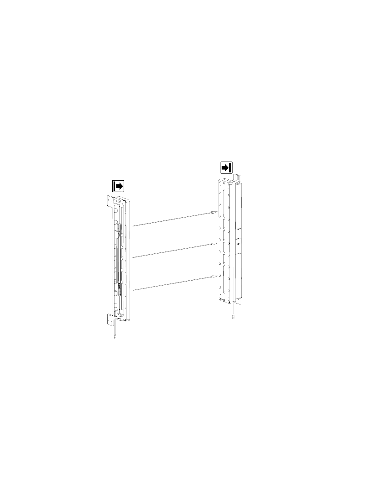
Figure 2: Sender indicators
wo light emitting diodes on the sender indicate the operational status:
T
Position LED color Display Labeling
1
2
Yellow Status indicator PWR
Red Fault indicator ERR
Complete overview of the light emitting diode statuses and their meanings: see "Dia
nostic LEDs", page 56.
g‐
14
O PE R AT I NG IN S TR U CT I ON S | deTem4 Core Ex 8022875/2019-03-04 | SICK
Subject to change without notice
Page 15
Receiver indicators
ERR
OSSD
1 2 3 4
2
1
3
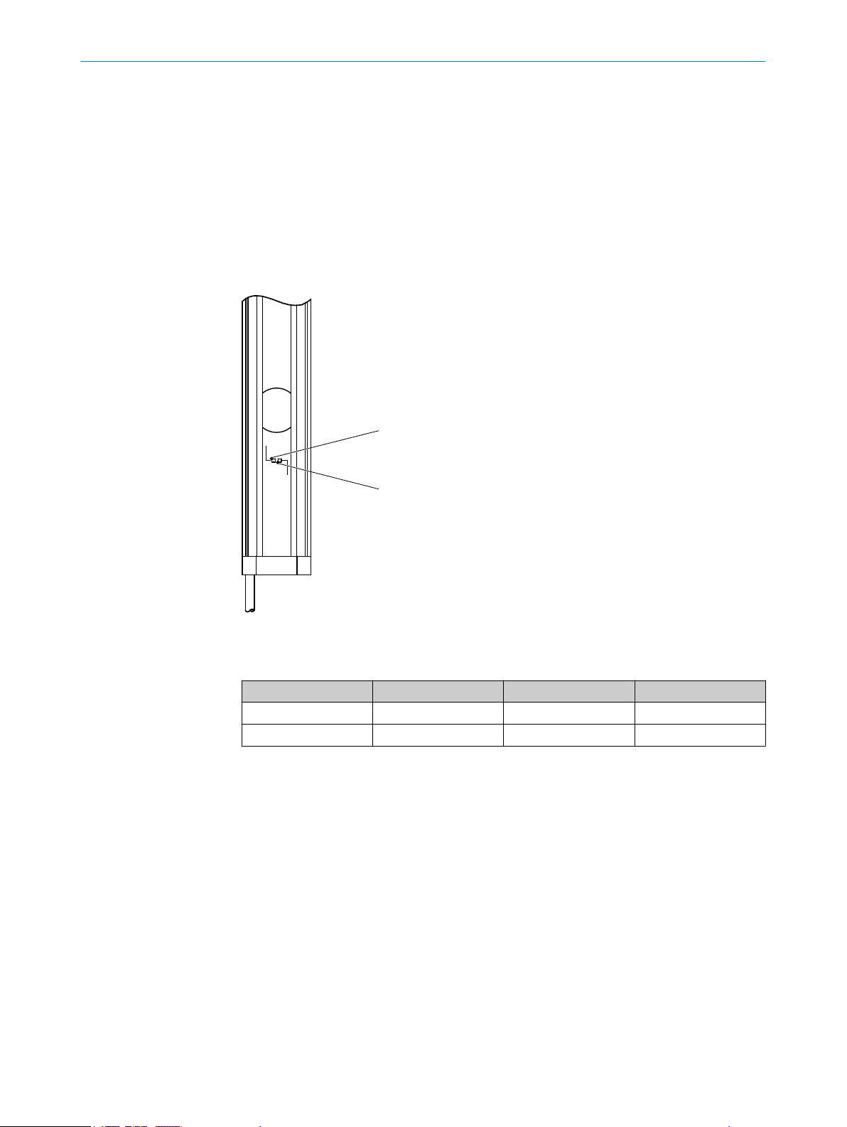
Figure 3: Receiver indicators
PRODUCT DESCRIPTION 3
S
ix light emitting diodes on the receiver indicate the operational status:
Position LED color Display Labeling
1
2
3
Red/green OSSD status OSSD
Red Fault indicator ERR
Blue Alignment quality 1, 2, 3, 4
The blue alignment quality light emitting diodes in combination with the red flashing
R LED also denote faults.
ER
Complete overview of the light emitting diode statuses and their meanings: see "Diag‐
nostic LEDs", page 56.
8022875/2019-03-04 | SICK O PE R AT I NG IN S TR U CT I ON S | deTem4 Core Ex
Subject to change without notice
15
Page 16
3 P
RODUCT DESCRIPTION
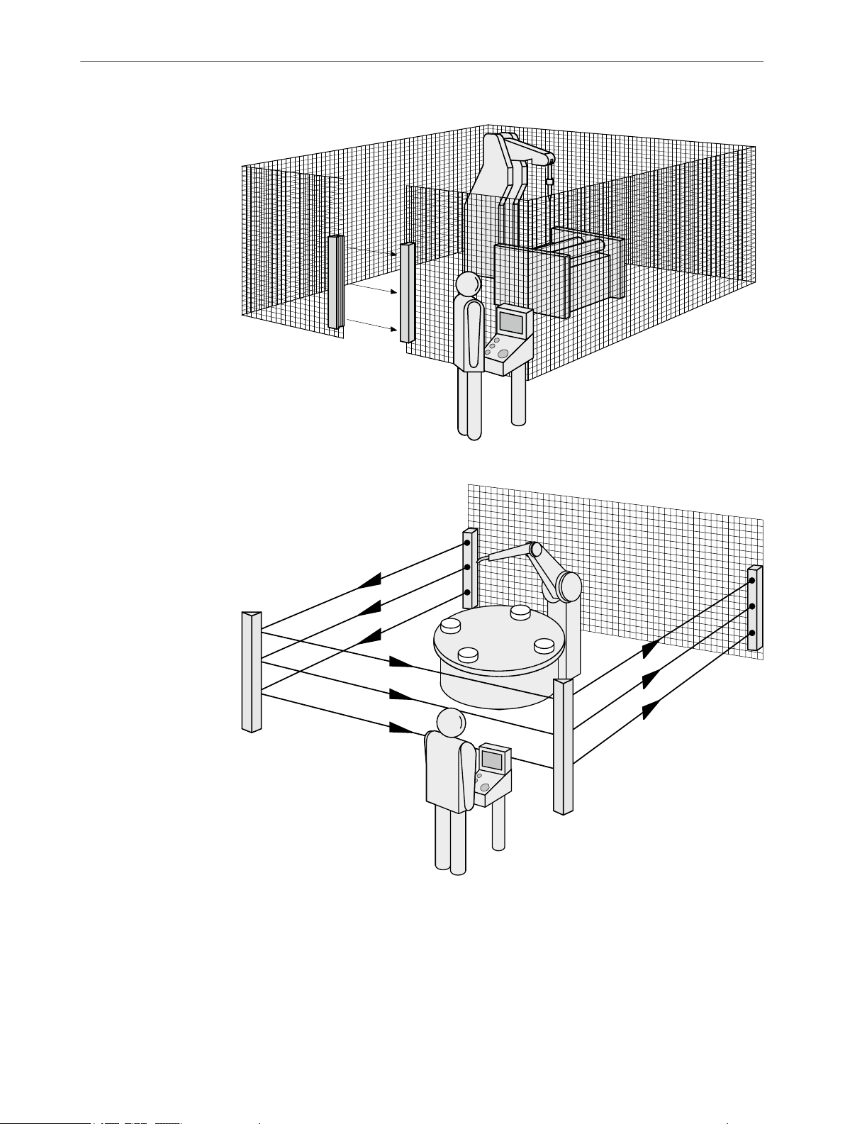
3.3 Example applications
Figure 4: Single-sided access protection
16
Figure 5: Multi-sided access protection
O PE R AT I NG IN S TR U CT I ON S | deTem4 Core Ex 8022875/2019-03-04 | SICK
Subject to change without notice
Page 17
4 Project planning
4.1 Manufacturer of the machine
DANGER
H
azard due to lack of effectiveness of the protective device
Persons and parts of the body to be protected may not be recognized in case of nonobservance.
Use of the multiple light beam safety device requires a risk assessment. Check
b
whether additional protective measures are required.
Comply with the applicable national regulations derived from the application (e.g.,
b
work safety regulations, safety rules, or other relevant safety guidelines).
Do not combine the components of the multiple light beam safety device with
b
components from other multiple light beam safety devices.
Apart from the procedures described in this document, the components of the
b
multiple light beam safety device must not be opened.
The components of the multiple light beam safety device must not be tampered
b
with or changed.
Improper repair of the protective device can lead to a loss of the protective func‐
b
tion. Do not carry out any repairs on the device components.
PROJECT PLANNING 4
4.2 Operating entity of the machine
DANGER
H
azard due to lack of effectiveness of the protective device
Persons and parts of the body to be protected may not be recognized in case of nonobservance.
Changes to the electrical integration of the multiple light beam safety device in the
b
machine control and changes to the mechanical mounting of the multiple light
beam safety device necessitate a new risk assessment. The results of this risk
assessment may require the operating entity of the machine to meet a manufac‐
turer’s obligations.
Apart from the procedures described in this document, the components of the
b
multiple light beam safety device must not be opened.
The components of the multiple light beam safety device must not be tampered
b
with or changed.
Improper repair of the protective device can lead to a loss of the protective func‐
b
tion. Do not carry out any repairs on the device components.
4.3 Design
This chapter contains important information about the design.
Information on the individual steps for mounting the device: see "Mounting", page 29.
8022875/2019-03-04 | SICK O PE R AT I NG IN S TR U CT I ON S | deTem4 Core Ex
Subject to change without notice
17
Page 18
ROJECT PLANNING
4 P
DANGER
azard due to lack of effectiveness of the protective device
H
Persons and parts of the body to be protected may not be recognized in case of non-
observance.
Make sure that the following design requirements are met so that the multiple
b
light beam safety device can fulfill its protective function.
Sender and receiver must be arranged such that persons or parts of the body
°
are reliably detected when they enter the hazardous area.
Ensure that nobody can pass under the lowest light beam, pass over the
°
highest light beam, get between two light beams, or pass by the side of the
protective device.
If people can stay between the protective device and the hazardous point
°
without being detected, check if additional protective measures (e.g., restart
interlock) are required.
4.3.1 Scanning range and beam separation
Important information
DANGER
H
azard due to lack of effectiveness of the protective device
Persons and parts of the body to be protected may not be recognized in case of nonobservance.
The multiple light beam safety device can only be mounted to machines on which
b
the protective field width does not change when the device is switched on.
Beam separation and number of beams
he beam separation is the distance between two adjacent light beams, measured
T
from the center of one beam to the center of the next.
The beam separation and number of beams depend on the device variant.
Scanning range
T
he scanning range is the maximum dimension of the light path between sender and
receiver. It depends on the device variant.
The scanning range is reduced by using deflector mirrors.
Further topics
"Minimum dis
•
"Technical data", page 60
•
"Deflector mirrors", page 69
•
4.3.2 Minimum distance from the hazardous point
A minimum distance must be maintained between the multiple light beam safety
de
vice and the hazardous point. This distance is required to prevent a person or part of
the body from reaching the hazardous area before the dangerous state of the machine
state has completed.
tance from reflective surfaces", page 20
18
Calculating the minimum distance according to ISO 13855
The calculation of the minimum distance is based on international or national stan‐
dards and statutory requirements applicable at the place of installation of the machine.
O PE R AT I NG IN S TR U CT I ON S | deTem4 Core Ex 8022875/2019-03-04 | SICK
Subject to change without notice
Page 19

If the minimum distance is calculated according to ISO 13855, then it depends on the
f
ollowing points:
Machine stopping time (time interval between triggering the sensor function and
•
the end of the machine’s dangerous state)
Response time of the protective device, see "Technical data", page 60
•
Approach speed of personnel
•
Type of approach: orthogonal (at right angles)
•
Parameters specified based on the application
•
For the USA (scope of OSHA and ANSI), different regulations may apply, e.g.:
a) Laws: Code of Federal Regulations, Title 29 (CFR29) Part 1910.217
b) Standards: ANSI B11.19
Complementary information
A
dditional information is available in the ISO 13855 standard and in the Guidelines
Safe Machinery.
SICK offers a stopping/run-down time measurement service in many countries.
4.3.2.1 Calculating minimum distance from the hazardous point
PROJECT PLANNING 4
Important information
DANGER
Minimum distance from the hazardous point is too small
The dangerous state of the machine may not be stopped or not be stopped in a timely
manner due to a minimum distance that is too small.
Calculate the minimum distances for the machine in which the multiple light beam
b
safety device is integrated.
When mounting the multiple light beam safety device, observe the minimum dis‐
b
tance.
Approach
he example shows the calculation of the minimum distance for an orthogonal (at right
T
angles) approach to the multiple light beam safety device. Depending on the applica‐
tion and the ambient conditions, a different calculation may be required (e.g., at a dif‐
ferent angle to the direction of approach or an indirect approach).
1. Calculate S using the following formula:
S = 1,600 mm/s × T + C
where:
S = minimum dis
°
T = machine stopping time + response time of the protective device after
°
interruption in the light path in seconds (s)
C = supplement in accordance with ISO 13855:
°
The reach/approach speed is already included in the formula.
If it is not possible to reach over the protective device: C = 850 mm
•
If it is possible to reach over the protective device, the value CRO must be
•
used for C in accordance with ISO 13855, provided that this is greater
than 850 mm: C ≥ 850 mm and C ≥ C
tance in millimeters (mm)
RO
8022875/2019-03-04 | SICK O PE R AT I NG IN S TR U CT I ON S | deTem4 Core Ex
Subject to change without notice
19
Page 20
3
4
1
2
4 P
ROJECT PLANNING
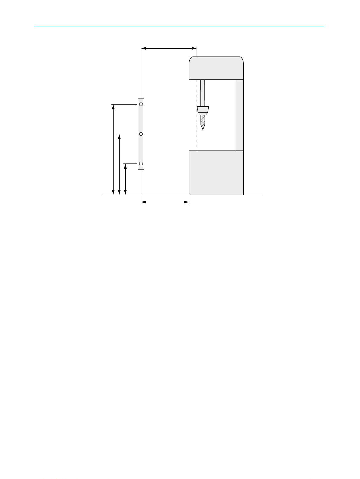
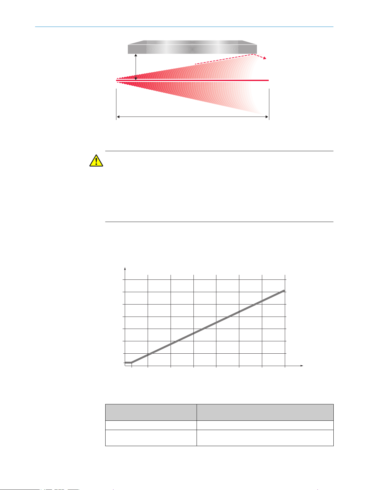
Figure 6: Minimum distance from the hazardous point
Minimum distance S
1
Height of the light beams above ground
2
Hazardous point
3
Depending on the application and distance, persons must be prevented from standing
4
be
hind the protective device.
Example calculation
Mac
hine stopping time = 290 ms
Response time after interruption of the light path = 20 ms
T = 290 ms + 20 ms = 310 ms = 0.31 s
S = 1,600 mm/s × 0.31 s + 850 mm = 1,346 mm
4.3.3 Minimum distance from reflective surfaces
Overview
T
he light beams from the sender may be deflected by reflective surfaces and dispersive
media. This can prevent an object from being detected.
Therefore, all reflective surfaces and objects (e.g., material bins, machine table, etc.)
must maintain a minimum distance (a) from the light beams. This minimum distance
(a) must be maintained on all sides of the light beams. This applies in horizontal, verti‐
cal, and diagonal directions as well as at the ends of the multiple light beam safety
device. The same area must be free of dispersive media (e.g., dust, fog, or smoke).
The minimum distance (a) depends on the distance (D) between sender and receiver.
20
O PE R AT I NG IN S TR U CT I ON S | deTem4 Core Ex 8022875/2019-03-04 | SICK
Subject to change without notice
Page 21
rs
D
a
10 20 30 40 50 60 70 D/
m
500
1000
2000
1500
2500
3000
3500
a/mm
131
3
PROJECT PLANNING 4
Figure 7: Minimum distance from reflective surfaces
Important information
DANGER
H
azard due to lack of effectiveness of the protective device
Reflective surfaces and dispersive media can prevent persons or parts of the body to
be protected from being properly reflected and therefore, they remain undetected.
Make sure that all reflective surfaces and objects maintain a minimum distance
b
from the light beams.
Make sure that no dispersive media (e.g., dust, fog, or smoke) are within the calcu‐
b
lated minimum distance from the light beams.
Determining minimum distance to reflective surfaces
1.
Determine the distance between sender and receiver D in meters (m)
2. Read the minimum distance a in millimeters (mm) in the graph or calculate it
based on the respective formula from table 1:
Figure 8: Graph, minimum distance from reflective surfaces
able 1: Formula for calculating the minimum distance from reflective surfaces
T
Distance between sender and
eceiver D in m
r
D ≤ 3 m a = 131 mm
D > 3 m a = tan (2.5°) × 1,000 mm/m × D = 43.66 × 1 mm/m ×
Calculating the minimum distance from reflective sur‐
faces a in mm
D
8022875/2019-03-04 | SICK O PE R AT I NG IN S TR U CT I ON S | deTem4 Core Ex
Subject to change without notice
21
Page 22
s
rs
r
!
"
"
!
s
rs
r
ROJECT PLANNING
4 P
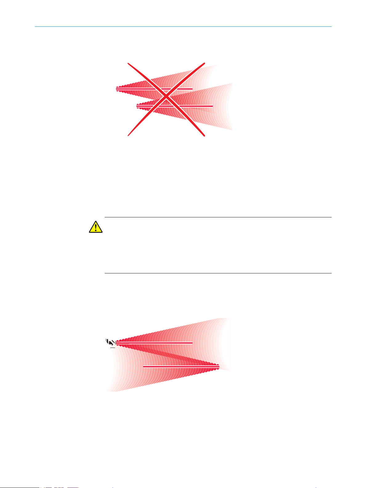
4.3.4 Protection against interference from systems in close proximity to each other
Overview
1
Figure 9: Preventing mutual interference from system
The infrared light beams of the sender of system 1 can interfere with the receiver of
system 2. This can disrupt the protective function of system 2. This would mean that
the operator is at risk.
Avoid such installation situations or take appropriate action, e.g., install optically
opaque partitions or reverse the direction of transmission of a system.
and system
2
Important information
DANGER
azard due to lack of effectiveness of the protective device
H
Systems of multiple light beam safety devices in close proximity to each other can
mutually interfere with each other.
Use suitable measures to prevent interference between systems in close proximity
b
to each other.
4.3.4.1 Using reversed direction of transmission
The direction of transmission of the system 2 c
switching the positions of the sender and receiver. With reversed direction of mounting,
the receiver 2 is not affected by the infrared light from the sender 1.
an be changed during mounting by
Figure 10: Trouble-free operation due to reversed direction of transmission of system
tem
2
4.4 Integrating into the electrical control
This chapter contains important information about integration in the electrical control.
22
O PE R AT I NG IN S TR U CT I ON S | deTem4 Core Ex 8022875/2019-03-04 | SICK
ormation about the individual steps for electrical installation of the device: see "Elec‐
Inf
trical installation", page 42.
1
and sys‐
Subject to change without notice
Page 23
PROJECT PLANNING 4
Requirements for use
T
he output signals of the protective device must be analyzed by downstream controllers
in such a way that the dangerous state of the machine is ended safely. Depending on
the safety concept, the signal is analyzed by, e.g., safety relays or a safety controller.
DANGER
azard due to lack of effectiveness of the protective device
H
In the case of non-compliance, it is possible that the dangerous state of the machine
may not be stopped or not stopped in a timely manner.
Make sure that the following control and electrical requirements are met so that
b
the multiple light beam safety device can fulfill its protective function.
t be possible to electrically influence the control of the machine.
It mus
•
The electrical control of the machine must meet the requirements of IEC 60204-1.
•
Depending on the regulations which apply at the place of installation, a restart
•
interlock may be required. Because the multiple light beam safety device does not
have this function, it must be implemented in the external control if required.
When using a safety controller, different signal levels of both OSSDs must be
•
detected depending on the regulations which apply at the place of installation or
the required reliability of the safety function. The maximum discrepancy time toler‐
ated by the control must be selected according to the application.
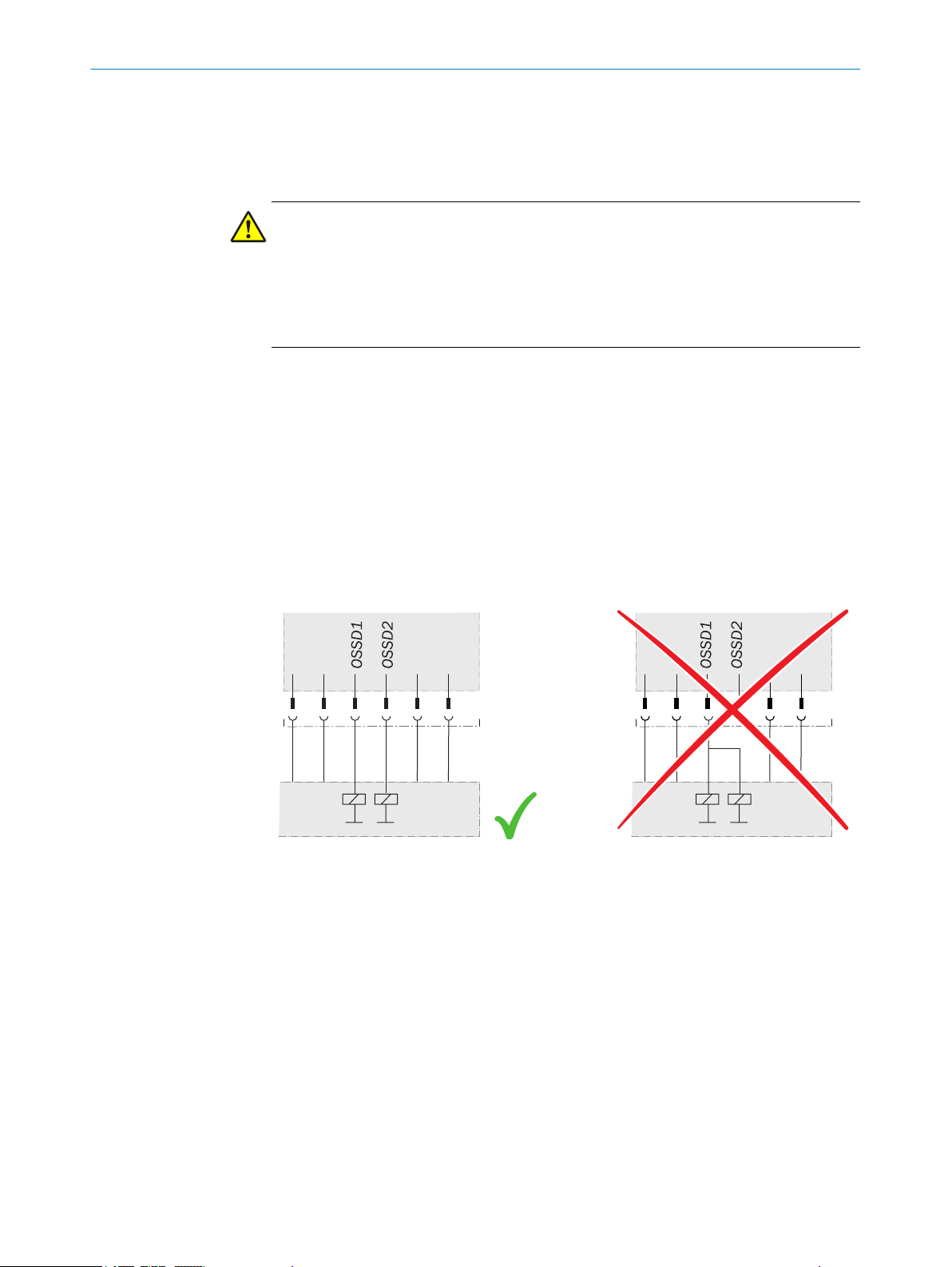
The OSSD1 and OSSD2 output signals must not be connected to each other.
•
In the machine controller, the signals of both OSSDs must be processed sepa‐
•
rately.
Figure 11: Dual-channel and isolated connection of OSSD1 and OSSD2
he machine must switch to the safe state at any time if at least one of the two
T
•
OSSDs switches to the OFF state.
Prevent the formation of a potential difference between the load and the protec‐
•
tive device. If you connect loads to the OSSDs (output signal switching devices)
that then also switch if controlled with negative voltage (e.g., electro-mechanical
contactor without reverse polarity protection diode), you must connect the 0 V con‐
nections of these loads and those of the corresponding protective device individu‐
ally and directly to the same 0 V terminal strip. In the event of a fault, this is the
only way to ensure that there can be no potential difference between the 0 V con‐
nections of the loads and those of the corresponding protective device.
8022875/2019-03-04 | SICK O PE R AT I NG IN S TR U CT I ON S | deTem4 Core Ex
Subject to change without notice
23
Page 24

ROJECT PLANNING
4 P
Figure 12: No potential difference between load and protective device
DANGER
H
azard due to lack of effectiveness of the protective device
In the case of non-compliance, it is possible that the dangerous state of the machine
may not be stopped or not stopped in a timely manner.
Downstream contactors must be positively guided and monitored depending on applic‐
able national regulations or required reliability of the safety function.
Make sure that downstream contactors are monitored (external device monitoring,
b
EDM).
Bec
b
ause the multiple light beam safety device does not have integrated external
device monitoring, this must be implemented in the external control, if required.
Requirements for the electrical control of the machine
th outputs are short-circuit protected to 24 V DC and 0 V. When the light path is
Bo
clear, the OSSDs are in the ON state. When a switch-off condition is present (e.g., inter‐
ruption in the light path), the OSSDs are in the OFF state. In the event of a device fault,
at least one OSSD is in the OFF state.
The multiple light beam safety device complies with the rules for electromagnetic com‐
patibility (EMC) for the industrial sector (Radio Safety Class A). Radio interference can‐
not be ruled out when used in residential areas.
DANGER
azard due to lack of effectiveness of the protective device
H
In the case of non-compliance, it is possible that the dangerous state of the machine
may not be stopped or not stopped in a timely manner.
Make sure that the following control and electrical requirements are met so that
b
the multiple light beam safety device can fulfill its protective function.
he external voltage supply of the multiple light beam safety device must be capa‐
T
•
ble of buffering brief power failures of 20 ms as specified in IEC 60204-1.
The power supply unit must provide safe isolation according to IEC 61140
•
(SELV/PELV). Suitable power supply units are available as accessories from SICK,
see "Accessories", page 67.
24
O PE R AT I NG IN S TR U CT I ON S | deTem4 Core Ex 8022875/2019-03-04 | SICK
Subject to change without notice
Page 25

4.4.1 Restart interlock
!
§" $
Overview
D
epending on the regulations which apply at the place of installation, a restart interlock
may be required.
The restart interlock prevents the machine from automatically starting up, for example
after a protective device has responded while the machine is operating or after chang‐
ing the machine’s operating mode.
NOTE
Because the multiple light beam safety device does not have an integrated restart inter‐
lock, this must be implemented in the external control, if required.
Principle of operation
Be
PROJECT PLANNING 4
fore the machine can be restarted, the operator must reset the restart interlock.
Figure 13: Schematic representation of operation with restart interlock
The dangerous state of the machine (!) is brought to an end if the light path is inter‐
rupted (") and is not re-enabled (§) until the operator presses the reset pushbutton
located outside the hazardous area ($). The machine can then be restarted.
Depending on the applicable national regulations, there must be a restart interlock if a
person can stand behind the protective field. Observe IEC 60204-1.
4.4.2 External device monitoring (EDM)
Overview
T
he external switching elements (external device monitoring, EDM) must be inspected
in line with the regulations which apply at the place of installation or the required relia‐
bility of the safety function.
The external device monitoring (EDM) monitors the status of downstream contactors.
In order to use the external device monitoring, positively guided contactors must be
used to switch off the machine. If the auxiliary contacts of the positively guided contac‐
tors are connected to the external device monitoring, the external device monitoring
checks whether the contactors drop off when the OSSDs are switched off.
Important information
NOTE
Because the multiple light beam safety device does not have integrated external device
monitoring, this must be implemented in the external control, if required.
8022875/2019-03-04 | SICK O PE R AT I NG IN S TR U CT I ON S | deTem4 Core Ex
Subject to change without notice
25
Page 26

S34 S21S35 S22
S33 S12S11 S31
14A2 24 32
13A1 23 31
UE48-2OS2D2
K1 K2
S1
K1
K2
OSSD1
OSSD2
n.c.
GND
+24V
1
2
3
4
5
+24V
n.c.
GND
n.c.
n.c.
1
2
3
4
5
24 VDC
0 VDC
4 P
ROJECT PLANNING
4.4.3 Connection diagrams
Connection diagram for UE48-2OS with restart interlock and external device monitor‐
in
g
4.5 Testing plan
Figure 14: Connection diagram for UE48-2OS with restart interlock and external device monitor‐
g
in
The multiple light beam safety device can be connected to the UE48-2OS switching
amplifiers. It is operated with restart interlock and external device monitoring.
Operating principle
When the protective field is clear, the OSSD1 and OSSD2 outputs carry voltage. The
system can be switched on when K1 and K2 are in the de-energized position. Pressing
the S1 button switches on the UE48 switching amplifier. Contacts 13-14 and 23-24 of
the UE48 activate the K1 and K2 contactors.
When the protective field is interrupted, the OSSD1 and OSSD2 outputs carry no volt‐
age. The UE48 switches off and K1, K2 are deactivated.
Fault analysis
Failure of K1 and K2 does not cause the loss of the shut-down function. Cross-circuits
and short-circuits of the OSSD1 and OSSD2 outputs are recognized and lead to the
locking state. It is recognized if the K1 or K2 contactors do not de-energize.
The manufacturer of the machine and the operating entity must define all required
c
hecks. The definition must be based on the application conditions and the risk assess‐
ment and must be documented in a traceable manner.
When defining the check, please note the following:
b
Define the type and execution of the check.
°
Define the frequency of the check.
°
Notify the machine operators of the check and instruct them accordingly.
°
26
O PE R AT I NG IN S TR U CT I ON S | deTem4 Core Ex 8022875/2019-03-04 | SICK
Subject to change without notice
Page 27

PROJECT PLANNING 4
The following checks are often defined in connection with a protective device:
Chec
•
•
Check during commissioning and modifications
The check must detect if it is possible to enter the hazardous area without being
detected.
The following points are often helpful for the definition of the check:
•
•
•
•
•
•
•
•
b
k during commissioning and modifications
Regular check
Does the check have to be completed by quality safety personnel?
Can the check be completed by personnel specially qualified and authorized per‐
sonnel?
Does the check have to be documented in a traceable manner?
Can the check be carried out according to a check list (see "Checklist for initial
commissioning and commissioning", page 73)?
Do the machine operators know the function of the protective device?
Have the machine operators been trained to work on the machine?
Have the machine operators been notified about modifications on the machine?
Does the hazardous area to be secured have to be checked with a test rod, see
"Test rod check", page 27?
Define all guidelines for the check.
4.5.1 Test rod check
Regular check
T
he check must detect if it is possible to enter the hazardous area without being
detected. Such possibilities may exist due to modifications, manipulations or external
influences.
The following points are often helpful for the definition of the check:
Which check must be carried out and how is it carried out?
•
Test rod check, page 27
°
Visual check of the machine and the protective device, page 28
°
How often does the check have to be carried out?
•
Do the machine operators have to be notified of the check and do they need to be
•
instructed accordingly?
Define all guidelines for the check.
b
Overview
T
he light beam is covered with an opaque test rod (minimum diameter of 30 mm).
When the light beam is covered, the OSSD LED on the receiver must light up red. The
check is carried out for each light beam and at multiple positions between the sender
and the receiver.
Important information
DANGER
azard due to unexpected starting of the machine
H
Make sure that the dangerous state of the machine is and remains switched off
b
during the check.
Make sure that the outputs of the multiple light beam safety device do not affect
b
the machine during the check.
8022875/2019-03-04 | SICK O PE R AT I NG IN S TR U CT I ON S | deTem4 Core Ex
Subject to change without notice
27
Page 28

ROJECT PLANNING
4 P
DANGER
azard due to lack of effectiveness of the protective device
H
Persons and parts of the body to be protected may not be recognized in case of non-
observance.
Do not operate the machine if the OSSD LED lights up green during the test!
If the OSSD LED lights up green during the test, even if only briefly, work must stop
b
at the machine.
In this case, the mounting and electrical installation of the multiple light beam
b
safety device must be checked by appropriately qualified safety personnel.
Prerequisites
he OSSD LED lights up green.
T
•
Approach
1. Cover a light beam completely.
✓
The OSSD LED on the receiver lights up red.
2. Enable the light beam.
✓
The OSSD LED on the receiver lights up green.
3. Carry out the check for each light beam.
4. Carry out the check at the following positions:
Immediately in front of the sender
°
In the middle, between the sender and the receiver (or between the deflector
°
mirrors)
Immediately in front of the receiver
°
Directly before and after each deflector mirror (if installed)
°
4.5.2 Visual check of the machine and the protective device
The following points are often helpful for the definition of the check:
H
as the machine been retrofitted?
•
Have machine parts been removed?
•
Have modifications been made to the surroundings of the machine?
•
Have the protective device or its parts been dismantled?
•
Is it possible to enter the hazardous area without being detected?
•
Is the protective device damaged?
•
Is the protective device severely contaminated?
•
Is the front screen contaminated, scratched or destroyed?
•
Are there any damaged cables or open cable ends?
•
If one of the points applies, the machine should be shut down immediately. In this case,
the machine and the protective device must be checked by appropriately qualified
safety personnel.
28
O PE R AT I NG IN S TR U CT I ON S | deTem4 Core Ex 8022875/2019-03-04 | SICK
Subject to change without notice
Page 29

5 Mounting
5.1 Safety
MOUNTING 5
Important information
DANGER
Ris
k of ignition or explosion
Disconnect the voltage supply before starting to mount the explosion-proof enclo‐
b
sure to avoid igniting hazardous atmospheres.
Only reconnect the voltage supply once you have completed the mounting process.
b
DANGER
k of ignition or explosion
Ris
If you have to remove the cover when working on the multiple light beam safety
b
device, make sure that the joints and o-ring are clean and undamaged before refit‐
ting the cover.
DANGER
k of ignition or explosion
Ris
The multiple light beam safety device must be mounted so that there is a gap of
b
more than 30 mm between all other objects and the flange joints between the
housing and the cover.
DANGER
D
angerous state of the machine
Make sure that the dangerous state of the machine is (and remains) switched off
b
during mounting, electrical installation, and commissioning.
Make sure that the outputs of the multiple light beam safety device do not affect
b
the machine during mounting, electrical installation, and commissioning.
DANGER
H
azard due to lack of effectiveness of the protective device
If unsuitable brackets are used or if subjected to excessive vibrations, the device may
become detached or damaged.
Persons and parts of the body to be protected may not be recognized in case of nonobservance.
Only use SICK-approved brackets for mounting.
b
Take appropriate measures for vibration damping if vibration and shock specifica‐
b
tions exceed the values and test conditions specified in the data sheet.
8022875/2019-03-04 | SICK O PE R AT I NG IN S TR U CT I ON S | deTem4 Core Ex
Subject to change without notice
29
Page 30

5 MOUNTING
DANGER
azard due to lack of effectiveness of the protective device
H
Persons and parts of the body to be protected may not be recognized in case of non-
observance.
Do not do repair work on device components.
b
Do not make changes to or manipulate device components.
b
Apart from the procedures described in this document, the device components
b
must not be opened.
CAUTION
k of injury due to heavy weight
Ris
Lifting and moving heavy loads may cause injury.
Unsecured heavy loads may, for example, fall over and cause bruising.
Only lift the device using equipment or two persons.
b
Wear suitable protective clothing and safety shoes.
b
NOTE
Mount t
he device in the following order.
5.2 Unpacking
5.3 Mounting
Prerequisites
T
he multiple light beam safety device has been designed correctly.
•
Further topics
"Design", page 17
•
Approach
1.
Check the components for completeness and the integrity of all parts.
2. Please contact your respective SICK subsidiary should you have any complaints.
Further topics
"Scope of delivery", page 66
•
Important information
NOTE
ead this section in full before mounting the brackets.
R
b
Read the information on aligning the sender and receiver, see "Sender and
b
receiver alignment", page 47
30
DANGER
Ris
k of ignition or explosion
Disconnect the voltage supply before starting to mount the explosion-proof enclo‐
b
sure to avoid igniting hazardous atmospheres.
Only reconnect the voltage supply once you have completed the mounting process.
b
O PE R AT I NG IN S TR U CT I ON S | deTem4 Core Ex 8022875/2019-03-04 | SICK
Subject to change without notice
Page 31

MOUNTING 5
DANGER
k of ignition or explosion
Ris
If you have to remove the cover when working on the multiple light beam safety
b
device, make sure that the joints and o-ring are clean and undamaged before refit‐
ting the cover.
DANGER
H
azard due to lack of effectiveness of the protective device
Persons or parts of the body to be protected may not be recognized or not recognized in
time in case of non-observance.
Take account of the minimum distances calculated for the machine: see "Mini‐
b
mum distance from the hazardous point", page 18, see "Minimum distance from
reflective surfaces", page 20.
Mount multiple light beam safety devices such that nobody can pass under the
b
lowest light beam, pass over the highest light beam, get between two light beams,
or pass by the side of the protective device.
DANGER
H
azard due to lack of effectiveness of the protective device
Persons and parts of the body to be protected may not be recognized in case of nonobservance.
The end with the cable connection must point in the same direction for the sender
b
and receiver.
Mounting instructions
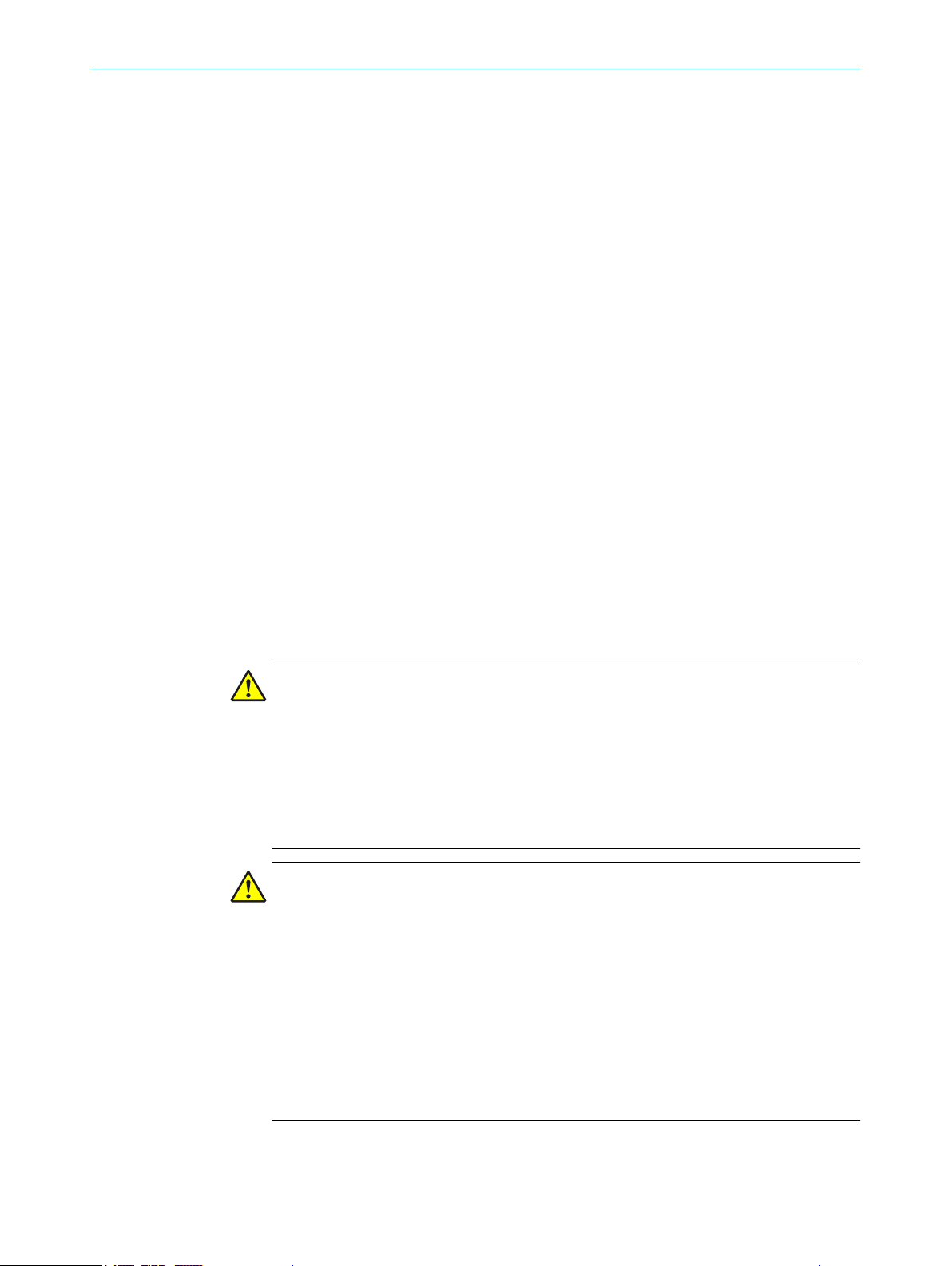
Figure 15: Sender and receiver must not be installed at 180° rotated relative to each other
Approach
If the multiple light beam safety device in pre-mounted condition has been pur‐
1.
chased, please skip this step.
First mount the multiple light beam safety device in the explosion-proof enclosure
using the two supplied FlexFix brackets and risers. The FlexFix bracket makes it
possible to rotate the sender and receiver around the axis of the device and to
8022875/2019-03-04 | SICK O PE R AT I NG IN S TR U CT I ON S | deTem4 Core Ex
Subject to change without notice
31
Page 32
5 MOUN
TING
align them accurately. In addition to the FlexFix brackets, the risers must also be
used t
o mount the multiple light beam safety device as close to the window on the
cover as possible.
2. Install the cable glands if necessary.
3. Secure the handles supplied onto the enclosure cover.
4. Mount the multiple light beam safety device in the explosion-proof enclosure on
the machine. The explosion-proof enclosure can either be attached directly or
using the alignment bracket (available as an accessory).
5.3.1 Mount the multiple light beam safety device in the explosion-proof enclosure (only if being used in
Nor
th America)
Important information
NOTE
If t
he device in pre-mounted condition has been purchased, please skip this section.
DANGER
Risk of ignition or explosion
Use fixing screws with a yield point of at least 640 MPa to attach the cover to the
b
explosion-proof enclosure.
Approach
1.
Unscrew the fixing screws on the cover and remove the cover from the explosionproof enclosure.
2. Secure the risers and the FlexFix brackets in the explosion-proof enclosure using
the supplied M5 screws.
3. Tighten the fixing screws on the FlexFix mount brackets with a torque of 5 to 6 Nm.
Too high a torque could damage the brackets while too low a torque does not pro‐
vide sufficient protection against vibration.
4. Mount the multiple light beam safety device on the FlexFix brackets so that the
connecting cable is at the same end of the explosion-proof enclosure as the 3/4"
NPT opening. Do not tighten the fixing screws at this point.
32
O PE R AT I NG IN S TR U CT I ON S | deTem4 Core Ex 8022875/2019-03-04 | SICK
Subject to change without notice
Page 33
MOUNTING 5
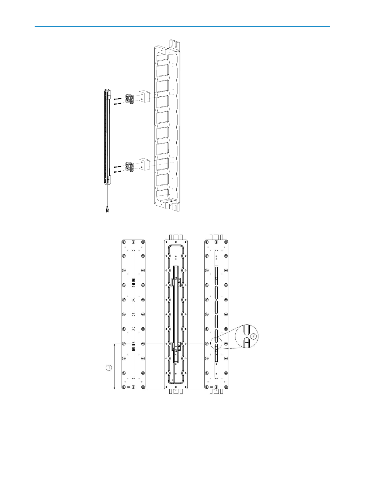
Figure 16: Mount the multiple light beam safety device in the explosion-proof enclosure.
Figure 17: Align the multiple light beam safety device in the explo‐
oof enclosure.
sion-pr
Measure the distance from the end of the cover to the first rib. Position the multiple light
1
am safety device so that the rib is between two optical lenses.
be
Detailed view
2
8022875/2019-03-04 | SICK O PE R AT I NG IN S TR U CT I ON S | deTem4 Core Ex
Subject to change without notice
33
Page 34

5 MOUN
TING
Approach
5.
Rotate the multiple light beam safety device in the FlexFix brackets so that the
front screen of the device faces the opening in the explosion-proof enclosure. The
infra-red rays must be able to pass through the window in the cover without
obstruction.
6. Tighten the screws used to secure the multiple light beam safety device in the
FlexFix brackets with a torque of 2.5 to 3 Nm.
7. Guide the connecting cable through the 3/4" NPT opening.
8. If a cable gland is required, follow the instructions to mount the gland, see "Mount
the optional cable gland", page 34.
9. Fit the cover to the explosion-proof enclosure using the supplied fixing screws and
washers. Tighten the fixing screws with a torque of 11.5 to 14.5 Nm.
NOTE
he washers must be used to obtain enclosure rating IP 66.
T
5.3.2 Mount the optional cable gland
Overview
D
epending on national regulations and requirements, a cable gland may have to be
installed. The cable gland is available as an accessory.
Important information
DANGER
Risk of ignition or explosion
Check the 3/4" NPT opening on the thread for damage.
b
Do not use the device if the thread for the 3/4" NPT opening is damaged.
b
Approach
Guide the cable through the cable gland.
1.
2. Screw the cable gland into the 3/4" NPT opening on the explosion-proof enclosure.
3. Pull the collar on the cable gland so that the cable is securely attached.
5.3.3 Mount the handles to the cover of the explosion-proof enclosure
Approach
1.
Use the supplied M6 screws to secure the two handles onto the cover of the explo‐
sion-proof enclosure.
2. Tighten the screws with a torque of 4.5 to 5 Nm.
34
O PE R AT I NG IN S TR U CT I ON S | deTem4 Core Ex 8022875/2019-03-04 | SICK
Subject to change without notice
Page 35

Figure 18: Mounting of the handles
MOUNTING 5
5.3.4 Mount the multiple light beam safety device
General notes
F
ind a place to mount the multiple light beam safety device that is stable enough
b
to hold its weight.
Mount the sender and receiver on a level surface.
b
Mount the sender and receiver at the same height.
b
The end with the connecting cable must point in the same direction for both
b
devices.
Figure 19: The sender and receiver are mounted incorrectly
Sender and r
b
Make sure that the sender and receiver are aligned correctly. The optical lens sys‐
b
eceiver must not be installed at 180° rotated relative to each other.
tems of the sender and the receiver must be located opposite one another.
8022875/2019-03-04 | SICK O PE R AT I NG IN S TR U CT I ON S | deTem4 Core Ex
Subject to change without notice
35
Page 36

4 x
4 x
WS
13 mm
Scope of delivery
Required tools
5 MOUN
TING
ssary, use a water level to check that the components are parallel.
If nece
b
The alignment bracket makes it possible to rotate the sender and receiver around
b
the axis of the device and to align them accurately; see "Sender and receiver align‐
ment", page 47.
5.3.4.1 Mounting the multiple light beam safety device without the alignment bracket
Figure 20: Mounting the multiple light beam safety device without the alignment bracket
Approach
rench size 13 mm.
Use w
b
Figure 21: Mounting the multiple light beam safety device without the alignment bracket:
S
tep 1
1. Using 6 to 8 revolutions, screw in the two M8 screws for mounting the lower end of
t
he explosion-proof enclosure. Make sure you leave enough space between the
screws and the mounting surface for the lower end of the explosion-proof enclo‐
sure.
36
O PE R AT I NG IN S TR U CT I ON S | deTem4 Core Ex 8022875/2019-03-04 | SICK
Subject to change without notice
Page 37

MOUNTING 5
Figure 22: Mounting the multiple light beam safety device without the alignment bracket:
tep 2
S
2. Position the explosion-proof enclosure on the two screws so that the mounting
hole
s are directly over the partly-tightened screws.
Figure 23: Mounting the multiple light beam safety device without the alignment bracket:
S
teps 3 and 4
3. Fix the upper end of the explosion-proof enclosure to the mounting surface using
t
wo M8 screws.
4. Tighten the two lower M8 screws.
8022875/2019-03-04 | SICK O PE R AT I NG IN S TR U CT I ON S | deTem4 Core Ex
Subject to change without notice
37
Page 38
2 x
Part no. 2072525
4 x
4 x
4 x
WS
13 mm
Scope of delivery
Required tools
5 MOUN
TING
5.3.4.2 Mounting the multiple light beam safety device with the alignment bracket
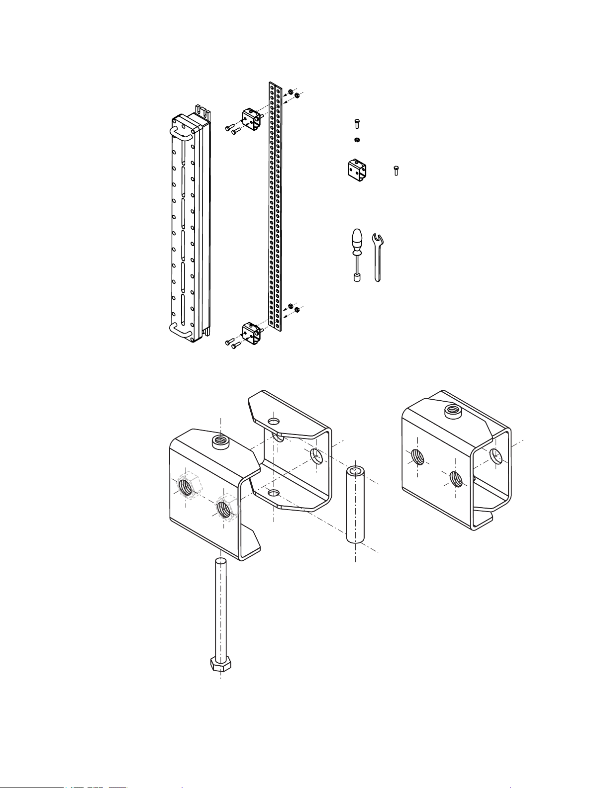
Figure 24: Mounting the multiple light beam safety device using the alignment brackets
38
Figure 25: Assembling the alignment brackets
O PE R AT I NG IN S TR U CT I ON S | deTem4 Core Ex 8022875/2019-03-04 | SICK
Subject to change without notice
Page 39

MOUNTING 5
Approach
1.
Mount the lower alignment bracket so that the threaded hole faces up and the
head of the lock screw faces down.
2. Rotate the alignment bracket as far to one side as possible. Secure the alignment
bracket on the open side by screwing the first M8 screw into the through hole.
3. Rotate the lower alignment bracket to the other side. Secure the alignment
bracket using the second M8 screw.
4. Mount the upper alignment bracket so that the threaded hole faces down and the
head of the lock screw faces up.
5. Rotate the upper alignment bracket as far to one side as possible. Secure the
alignment bracket on the open side by screwing the first M8 screw into the
through hole.
6. Rotate the upper alignment bracket to the other side. Secure the alignment
bracket using the second M8 screw.
Figure 26: Mounting the multiple light beam safety device using the alignment brackets:
teps 1 to 6
S
7. Using 6 to 8 revolutions, screw the two M8 screws for mounting the lower end of
t
he explosion-proof enclosure into the lower alignment bracket. Make sure you
leave enough space between the screws and the alignment bracket for the lower
end of the explosion-proof enclosure.
8022875/2019-03-04 | SICK O PE R AT I NG IN S TR U CT I ON S | deTem4 Core Ex
Subject to change without notice
39
Page 40

5 MOUN
TING
Figure 27: Mounting the multiple light beam safety device using the alignment brackets:
tep 7
S
8. Position the explosion-proof enclosure on the two screws so that the mounting
hole
s are directly over the partly-tightened screws.
Figure 28: Mounting the multiple light beam safety device using the alignment brackets:
S
tep 8
9. Fix the upper end of the explosion-proof enclosure to the upper alignment bracket
usin
g two M8 screws.
10. Tighten the two lower screws.
40
Figure 29: Mounting the multiple light beam safety device using the alignment brackets:
S
teps 9 and 10
11. Turn the multiple light beam safety device so that they face one another and so
t
hat the receiver receives the strongest signal possible.
O PE R AT I NG IN S TR U CT I ON S | deTem4 Core Ex 8022875/2019-03-04 | SICK
Subject to change without notice
Page 41

28 Nm to 28.5 Nm
28 Nm to 28.5 Nm
MOUNTING 5
Figure 30: Mounting the multiple light beam safety device using the alignment brackets:
teps 11 and 12
S
12. Tighten the locking screws on all alignment brackets with a torque of 28 to
28.5 Nm in or
der to secure the multiple light beam safety device in this position.
8022875/2019-03-04 | SICK O PE R AT I NG IN S TR U CT I ON S | deTem4 Core Ex
Subject to change without notice
41
Page 42

6 ELECTRICAL INSTALLATION
6 Electrical installation
6.1 Safety
Important information
DANGER
H
azard due to electrical voltage
Hazard due to unexpected starting of the machine
Make sure that the machine is (and remains) disconnected from the power supply
b
during the electrical installation.
Make sure that the dangerous state of the machine is (and remains) switched off
b
during electrical installation.
Make sure that the outputs of the multiple light beam safety device do not affect
b
the machine during electrical installation.
Only use an appropriate voltage supply, see "Technical data", page 60.
b
DANGER
ion Hazard
Ignit
Failure to observe this information could result in a risk of ignition
Always switch the voltage supply off before disconnecting a connecting cable from
b
the device.
Ensure that all electrical connections to the device or to the connections are pro‐
b
tected.
The IP enclosure rating for the connections and therefore for the device is only
b
guaranteed if the connections are protected. Otherwise foreign objects can get
into the terminal compartment. This can cause an explosion the next time the
device is switched on.
Put in place measures for ensuring supply reliability and delivery dependability.
b
DANGER
k of ignition or explosion
Ris
If you have to remove the cover when working on the multiple light beam safety
b
device, make sure that the joints and o-ring are clean and undamaged before refit‐
ting the cover.
DANGER
k of ignition or explosion
Ris
Disconnect the power supply before opening the explosion-proof enclosure to
b
avoid igniting hazardous atmospheres.
Do not reconnect the power supply until you have completed the electrical installa‐
b
tion.
42
O PE R AT I NG IN S TR U CT I ON S | deTem4 Core Ex 8022875/2019-03-04 | SICK
Subject to change without notice
Page 43
ELECTRICAL INSTALLATION 6
DANGER
k of ignition or explosion
Ris
Each connection to the protection earth (PE) on the explosion-proof enclosure
b
must use at least one wire with a cross-section meeting the requirements of the
table below.
Table 2: Minimum wire cross-section for protection earth (PE)
Wire cross-section of outer cable S Minimum wire cross-section of the corre‐
spondin
S ≤ 16 mm
16 mm2 < S
S > 35 mm
2
≤ 35 mm
2
S
2
16 mm
0.5 S
DANGER
H
azard due to electrical voltage
Hazard due to unexpected starting of the machine
Make sure that the machine is (and remains) disconnected from the power supply
b
during the electrical installation.
Make sure that the dangerous state of the machine is (and remains) switched off
b
during electrical installation.
Make sure that the outputs of the multiple light beam safety device do not affect
b
the machine during electrical installation.
Only use an appropriate voltage supply, see "Technical data", page 60.
b
g protection earth wire S
2
P
DANGER
H
azard due to lack of effectiveness of the protective device
The dangerous state may not be stopped in the event of non-compliance.
Always connect the two OSSDs separately. The two OSSDs must not be connected
b
to each other.
Connect the OSSDs such that the machine controller processes both signals sepa‐
b
rately.
DANGER
H
azard due to lack of effectiveness of the protective device
The dangerous state may not be stopped in the event of non-compliance.
Prevent the formation of a potential difference between the load and the protec‐
b
tive device.
Prerequisites
he multiple light beam safety device has been safely integrated into the control
T
•
system and the electrical system of the machine.
Mounting has been completed correctly.
•
8022875/2019-03-04 | SICK O PE R AT I NG IN S TR U CT I ON S | deTem4 Core Ex
Subject to change without notice
43
Page 44
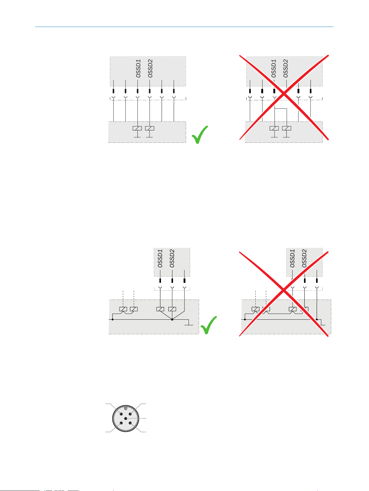
12
3
4
5
6 ELECTRICAL INSTALLATION
Example: Isolated connection of OSSD1 and OSSD2
Figure 31: Dual-channel and isolated connection of OSSD1 and OSSD2
Avoiding any potential difference between load and protective device
Pr
event the formation of a potential difference between the load and the protec‐
•
tive device. If you connect loads to the OSSDs (output signal switching devices)
that then also switch if controlled with negative voltage (e.g., electro-mechanical
contactor without reverse polarity protection diode), you must connect the 0 V con‐
nections of these loads and those of the corresponding protective device individu‐
ally and directly to the same 0 V terminal strip. In the event of a fault, this is the
only way to ensure that there can be no potential difference between the 0 V con‐
nections of the loads and those of the corresponding protective device.
Figure 32: No potential difference between load and protective device
Further topics
"Int
•
egrating into the electrical control", page 22
6.2 System connection (M12, 5-pin)
Figure 33: System connection (male connector, M12, 5-pin)
44
O PE R AT I NG IN S TR U CT I ON S | deTem4 Core Ex 8022875/2019-03-04 | SICK
Subject to change without notice
Page 45

ELECTRICAL INSTALLATION 6
Table 3: System connection pin assignment (male connector, M12, 5-pin)
Pin Wire color
1 Brown +24 V DC (voltage supply
2 White Reserved OSSD1 (output signal
3 Blue 0 V DC (voltage supply
4 Black Reserved OSSD2 (output signal
5 Gray Not connected Not connected
1)
Applies to the extension cables recommended as accessories.
1)
s S
ender r Receiver
+24 V DC (voltage supply
in
put)
input)
switching device 1)
0 V DC (voltage supply
input)
input)
switching device 2)
Connection diagrams for the electrical installation: see "Int
egrating into the electrical
control", page 22.
6.3 System connection via connection cable (M12, 5-pin to 8-pin)
An optional connection cable is available to connect the 5-pin system connection to an
e
xisting 8-pin female connector. The connection cable can be used to replace an exist‐
ing M4000 multiple light beam safety device with a deTem4 Core Ex multiple light
beam safety device, without having to route new cables.
8022875/2019-03-04 | SICK O PE R AT I NG IN S TR U CT I ON S | deTem4 Core Ex
Subject to change without notice
45
Page 46

OMMISSIONING
7 C
7 Commissioning
7.1 Safety
DANGER
H
azard due to lack of effectiveness of the protective device
When changes are made to the machine, the effectiveness of the protective device may
be affected unintentionally.
After every change to the machine and changes to the integration or operational
b
and secondary conditions of the multiple light beam safety device, check the pro‐
tective device for effectiveness and recommission as specified in this chapter.
DANGER
D
angerous state of the machine
Make sure that the dangerous state of the machine is (and remains) switched off
b
during mounting, electrical installation, and commissioning.
Make sure that the outputs of the multiple light beam safety device do not affect
b
the machine during mounting, electrical installation, and commissioning.
WARNING
azard due to lack of effectiveness of the protective device
H
Before commissioning the machine, make sure that the machine is first checked
b
and released by qualified safety personnel.
Only operate the machine with a perfectly functioning protective device.
b
DANGER
azard due to lack of effectiveness of the protective device
H
Persons and parts of the body to be protected may not be recognized in case of non-
observance.
1. Make sure that the optical properties of the protective housing of the sender and
receiver are not changed during operation, e.g., by:
Beading water, mist, frost, or ice formation on the protective housing. Remove
°
condensation of this kind or other types of contamination, then restart the
receiver.
Scratches or damage to the protective housing. Replace the protective hous‐
°
ing of the respective sender or receiver if its protective housing is scratched
or damaged.
2. Make sure that all reflective surfaces and objects maintain a minimum distance
from the protective field.
3. Make sure that no dispersive media (e.g., dust, fog, or smoke) are within the calcu‐
lated minimum distance from the protective field.
7.2 Overview
46
O PE R AT I NG IN S TR U CT I ON S | deTem4 Core Ex 8022875/2019-03-04 | SICK
Further topics
"Minimum dis
•
The mounting and electrical installation work must be completed before commissioning
a
s described in the following chapters:
tance from reflective surfaces", page 20
Subject to change without notice
Page 47

esign", page 17
"D
•
"Integrating into the electrical control", page 22
•
"Mounting", page 29
•
"Electrical installation", page 42
•
7.3 Switching on
After switching on, the sender and receiver initialize. All light emitting diodes of the
sender and r
ment quality using four blue light emitting diodes. Once the multiple light beam safety
device is aligned (OSSD LED: green), the alignment display switches off after a certain
period of time, and only the PWR LED of the sender and the OSSD LED of the receiver
continue to light up.
In the event of a fault, the red fault light emitting diode flashes on the respective
device. The red fault light emitting diode in combination with the blue light emitting
diodes show the cause of the fault on the side of the receiver, see "Troubleshooting",
page 56.
eceiver briefly light up. After initialization, the receiver displays the align‐
7.4 Sender and receiver alignment
Overview
COMMISSIONING 7
Af
ter mounting and electrical installation, the sender and receiver must be aligned with
each other.
Important information
DANGER
D
angerous state of the machine
Make sure that the dangerous state of the machine is (and remains) switched off
b
during the alignment process.
Make sure that the outputs of the multiple light beam safety device do not affect
b
the machine during the alignment process.
Further topics
ation of the alignment quality", page 50
"Indic
•
7.4.1 Aligning the sender and receiver
Important information
NOTE
gnment is not possible when mounting the device directly, then use the optional
If ali
alignment bracket.
Prerequisites
S
ender and receiver have been mounted at the correct height
•
Approach
1. Ensure that the multiple light beam safety device can rotate in the bracket. If
required, loosen the fixing screws a little.
2. Switch on the voltage supply for the multiple light beam safety device.
3. Roughly align the sender with the receiver by rotating it.
8022875/2019-03-04 | SICK O PE R AT I NG IN S TR U CT I ON S | deTem4 Core Ex
Subject to change without notice
47
Page 48

OMMISSIONING
7 C
4. Align the receiver with the sender. To do this, rotate the receiver so that as many
blue ali
5. If required, align the sender more precisely to the receiver so that as many align‐
ment quality light emitting diodes as possible light up on the receiver.
6. If required, align the receiver more precisely to the sender so that as many align‐
ment quality light emitting diodes as possible light up on the receiver.
7. When at least three (preferably four) alignment quality LEDs light up on the
receiver, fasten the components in the brackets. Torque: 28 Nm... 28.5 Nm.
8. Switch the voltage supply off and then on again.
9. Check the alignment quality light emitting diodes to make sure that the compo‐
nents are still correctly aligned with each other.
NOTE
Once t
availability is stable.
Please note that body parts or objects between the sender and receiver (e.g., hand,
tool, AR60 optional laser alignment aid) will impair the function of the alignment quality
LEDs. Remove all objects from this area to allow the alignment quality to be assessed.
Complementary information
gnment quality light emitting diodes as possible light up on the receiver.
hree blue alignment quality light emitting diodes light up, alignment is good and
T
he AR60 optional laser alignment aid can be used to facilitate alignment. To ensure
that the indication of the alignment quality cannot be impaired, place the AR60
optional laser alignment aid with the adapter between the light beams of the multiple
light beam safety device.
Since the AR60 optional laser alignment aid is positioned in the protective field of the
multiple light beam safety device with the adapter, a maximum of two blue alignment
quality LEDs light up and the OSSD LED lights up red. To check whether the OSSD LED
of the receiver lights up green, remove the AR60 optional laser alignment aid.
7.4.2 Aligning the sender, receiver, and deflector mirror
Approach
1.
Ensure that the sender and receiver are mounted correctly and, in particular, at
the right height.
2. Ensure that the multiple light beam safety device can rotate in the bracket. If nec‐
essary, loosen the fixing screws slightly.
3. Switch on the voltage supply for the multiple light beam safety device.
4. Place the laser alignment aid near the bottom light beam on the sender.
5. Rotate the sender and adjust the height of the mirror column so that the laser
beam hits the bottom mirror of the first mirror column.
The laser beam should hit the center of the mirror horizontally.
°
The laser beam should hit the mirror vertically with the same deviation from
°
the center of the mirror that the laser of the laser alignment aid has from the
bottom light beam.
6. Secure the sender in the brackets. Torque: 28 Nm ... 28.5 Nm.
The alignment may shift slightly when the screws are tightened. However, do
°
not correct the setting.
7. Place the laser alignment aid near the bottom light beam on the receiver.
8. Rotate the receiver so that the laser beam hits the bottom mirror of the first mirror
column.
The laser beam should hit the center of the mirror horizontally.
°
The laser beam should hit the mirror vertically with the same deviation from
°
the center of the mirror that the laser of the laser alignment aid has from the
bottom light beam.
48
O PE R AT I NG IN S TR U CT I ON S | deTem4 Core Ex 8022875/2019-03-04 | SICK
Subject to change without notice
Page 49

COMMISSIONING 7
9. Rotate the bottom mirror of the first mirror column so that the laser beam hits the
bo
ttom mirror of the second mirror column. If no other mirror column is available,
the laser beam must hit the bottom beam of the sender.
10. Repeat step 9 for the subsequent mirror columns, until the laser beam hits the
sender.
11. Perform steps 7 to 10 for all beams from the bottom to the top.
Align each individual mirror separately.
°
When deflecting using mirrors, the angle of incidence is the same as the
°
emergence angle. Rotating the mirror slightly results in a deflection that is
twice as great.
Only part of the original ray beam is ever transmitted via deflector mirrors.
°
The alignment tolerance is reduced with each additional deflection.
12. Switch the voltage supply off and then on again.
13. Check the alignment quality LEDs to make sure that the components are still cor‐
rectly aligned with each other.
NOTE
hree blue alignment quality light emitting diodes light up, alignment is good and
Once t
availability is stable.
Please note that body parts or objects between the sender and receiver (e.g., hand,
tool, AR60 optional laser alignment aid) will impair the function of the alignment quality
LEDs. Remove all objects from this area to allow the alignment quality to be assessed.
NOTE
he AR60 optional laser alignment aid can be used to facilitate alignment.
T
To ensure that the indication of the alignment quality is not impaired, place the AR60
optional laser alignment aid with the adapter between the light beams of the multiple
light beam safety device.
Further topics
"A
ccessories", page 67
•
7.4.3 Alignment with the alignment bracket
The alignment bracket offers you the following adjustment options for aligning the
sender and r
Rotate (± 45°)
•
eceiver with each other:
8022875/2019-03-04 | SICK O PE R AT I NG IN S TR U CT I ON S | deTem4 Core Ex
Subject to change without notice
49
Page 50

7 COMMISSIONING
Figure 34: Alignment bracket: rotate
7.4.4 Indication of the alignment quality
Important information
NOTE
Once three blue alignment quality light emitting diodes light up, alignment is good and
availability is stable.
Please note that body parts or objects between the sender and receiver (e.g., hand,
tool, AR60 optional laser alignment aid) will impair the function of the alignment quality
LEDs. Remove all objects from this area to allow the alignment quality to be assessed.
Indication of the alignment quality
able 4: Indication of the alignment quality
T
Indication Meaning
Alignment qual‐
y light emitting
it
diodes
No light emitting
ghts up
diode li
1 light emitting
diode lights up
2 light emitting
diodes light up
2 light emitting
s light up
diode
3 light emitting
s light up
diode
OSSD light emit‐
ting diode
O R
O R
O R
O Gr
O Gr
ed
ed
ed
een
een
Alignment is insufficient or a light beam is interrupted at
ast partially. The receiver cannot synchronize with the
le
sender.
Alignment is insufficient or a light beam is interrupted at
ast partially.
le
Alignment is insufficient or a light beam is interrupted at
ast partially.
le
Alignment is not yet sufficient for stable availability.
Alignment is good, stable availability.
1)
50
O PE R AT I NG IN S TR U CT I ON S | deTem4 Core Ex 8022875/2019-03-04 | SICK
Subject to change without notice
Page 51

Indication Meaning
Alignment qual‐
it
y light emitting
diodes
4 light emitting
diodes light up
OSSD light emit‐
ting diode
O Gr
een
Alignment is very good.
COMMISSIONING 7
o LED of
1)
If the light path is very long, there is a possibility that all four alignment quality light emitting diodes will
not light up even when alignment is excellent.
f. Ö LED flashes. O LED illuminates.
Further topics
"Dia
•
gnostic LEDs", page 56
7.5 Check during commissioning and modifications
The check must detect if it is possible to enter the hazardous area without being
de
tected.
C
arry out the checks according to the instructions from the manufacturer of the
b
machine and from the operating entity.
8022875/2019-03-04 | SICK O PE R AT I NG IN S TR U CT I ON S | deTem4 Core Ex
Subject to change without notice
51
Page 52

8 O
PERATION
8 Operation
8.1 Safety
DANGER
H
azard due to lack of effectiveness of the protective device
Persons and parts of the body to be protected may not be recognized in case of nonobservance.
Maintenance work, alignment work, fault diagnoses, and any changes to the inte‐
b
gration of the protective device in the machine must only be carried out by quali‐
fied personnel.
The effectiveness of the protective device must be checked following such work.
b
DANGER
H
azard due to lack of effectiveness of the protective device
Persons and parts of the body to be protected may not be recognized in case of nonobservance.
Make sure that the optical properties of the front screens of the sender and
b
receiver are not changed, e.g., by:
Beading water, mist, frost, or ice formation. If applicable, remove films or
°
other types of contamination, disconnect the voltage supply of the receiver
and then switch it back on.
Scratches or damage. Replace the device whose front screen is scratched or
°
damaged.
Make sure that all reflective surfaces and objects maintain a minimum distance
b
from the light beams.
Make sure that no dispersive media (e.g., dust, fog, or smoke) are within the calcu‐
b
lated minimum distance from the light beams.
NOTE
This document does not provide instructions for operating the machine in which the
multiple light beam safety device is integrated.
8.2 Regular thorough check
The check must detect if it is possible to enter the hazardous area without being
tected. Such possibilities may exist due to modifications, manipulations or external
de
influences.
C
arry out the checks according to the instructions from the manufacturer of the
b
machine and from the operating entity.
52
O PE R AT I NG IN S TR U CT I ON S | deTem4 Core Ex 8022875/2019-03-04 | SICK
Subject to change without notice
Page 53

9 Maintenance
9.1 Safety
DANGER
H
azard due to lack of effectiveness of the protective device
Persons and parts of the body to be protected may not be recognized in case of nonobservance.
b
b
b
DANGER
Ris
k of ignition or explosion
b
b
MAINTENANCE 9
Do not do repair work on device components.
Do not make changes to or manipulate device components.
Apart from the procedures described in this document, the device components
must not be opened.
Disconnect the voltage supply before any maintenance work is carried out to avoid
igniting hazardous atmospheres.
Only reconnect the voltage supply once you have completed the maintenance
work.
DANGER
k of ignition or explosion
Ris
If you have to remove the cover when working on the multiple light beam safety
b
device, make sure that the joints and o-ring are clean and undamaged before refit‐
ting the cover.
DANGER
k of ignition or explosion
Ris
Use fixing screws with a yield point of at least 640 MPa to attach the cover to the
b
explosion-proof enclosure.
9.2 Regular cleaning
Overview
D
epending on the ambient conditions of the multiple light beam safety device, the front
screens must be cleaned regularly and in the event of contamination. Static charges
can cause dust particles to be attracted to the front screen.
The weld spark guard and deflector mirrors must be cleaned regularly and in the event
of contamination.
Important information
DANGER
k of ignition or explosion
Ris
Static discharge could cause explosions in hazardous atmospheres.
Always use anti-static cleaning agents to prevent static charge.
b
Do not clean the device using a dry cloth.
b
8022875/2019-03-04 | SICK O PE R AT I NG IN S TR U CT I ON S | deTem4 Core Ex
Subject to change without notice
53
Page 54

AINTENANCE
9 M
DANGER
azard due to lack of effectiveness of the protective device
H
Persons and parts of the body to be protected may not be recognized in case of non-
observance.
Regularly check the degree of contamination on all components based on the
b
application conditions.
Observe the information on the regular rod test check.
b
DANGER
azard due to lack of effectiveness of the protective device
H
Persons and parts of the body to be protected may not be recognized in case of non-
observance.
Make sure that the optical properties of the front screens of the sender and
b
receiver are not changed, e.g., by:
Beading water, mist, frost, or ice formation. If applicable, remove films or
°
other types of contamination, disconnect the voltage supply of the receiver
and then switch it back on.
Scratches or damage. Replace the device whose front screen is scratched or
°
damaged.
Make sure that all reflective surfaces and objects maintain a minimum distance
b
from the light beams.
Make sure that no dispersive media (e.g., dust, fog, or smoke) are within the calcu‐
b
lated minimum distance from the light beams.
DANGER
H
azard due to unexpected starting of the machine
Make sure that the dangerous state of the machine is and remains switched off
b
during the cleaning.
Make sure that the outputs of the multiple light beam safety device do not affect
b
the machine during cleaning.
NOTICE
D
o not use any aggressive cleaning agents.
b
Do not use any abrasive cleaning agents.
b
We recommend anti-static cleaning agents.
b
We recommend the use of anti-static plastic cleaner (SICK part number 5600006)
b
and the SICK lens cloth (SICK part number 4003353).
Approach
1.
Remove dust from the front screen using a soft, clean brush.
2. Then wipe the front screen with a clean, damp cloth.
3. Check the position of the sender and receiver.
4. Check the effectiveness of the protective device. Information on how to check the
effectiveness.
Further topics
54
"T
est rod check", page 27
•
O PE R AT I NG IN S TR U CT I ON S | deTem4 Core Ex 8022875/2019-03-04 | SICK
Subject to change without notice
Page 55

9.3 Regular thorough check
The check must detect if it is possible to enter the hazardous area without being
tected. Such possibilities may exist due to modifications, manipulations or external
de
influences.
C
arry out the checks according to the instructions from the manufacturer of the
b
machine and from the operating entity.
MAINTENANCE 9
8022875/2019-03-04 | SICK O PE R AT I NG IN S TR U CT I ON S | deTem4 Core Ex
Subject to change without notice
55
Page 56

10 TROUBLESHOOTING
10 Troubleshooting
10.1 Safety
DANGER
H
azard due to lack of effectiveness of the protective device
Persons and parts of the body to be protected may not be recognized in case of non-
observance.
Immediately shut the machine down if the behavior of the machine cannot be
b
clearly identified.
Immediately put the machine out of operation if you cannot clearly identify or allo‐
b
cate the fault and if you cannot safely remedy the fault.
Secure the machine so that it cannot switch on unintentionally.
b
DANGER
H
azard due to unexpected starting of the machine
When any work is taking place, use the protective device to secure the machine or
b
to ensure that the machine is not switched on unintentionally.
DANGER
azard due to lack of effectiveness of the protective device
H
Persons and parts of the body to be protected may not be recognized in case of non-
observance.
b
b
b
NOTE
dditional information on troubleshooting can be found at the responsible SICK sub‐
A
sidiary.
10.2 Diagnostic LEDs
10.2.1 Fault indicators
In the event of a fault, the type of fault is indicated by the light emitting diode display on
t
he sender or receiver.
Sender
Table 5: Fault indicator on the sender
PWR-LED ERR-LED Possible cause Rectification
o o
Do not do repair work on device components.
Do not make changes to or manipulate device components.
Apart from the procedures described in this document, the device components
must not be opened.
No supply voltage or supply
v
oltage is too low or inter‐
nal fault
Check the voltage supply,
see "Technical data",
page 60.
Switch the voltage supply
off and then on again.
If the fault persists, replace
the sender, see "Ordering
information", page 66.
56
O PE R AT I NG IN S TR U CT I ON S | deTem4 Core Ex 8022875/2019-03-04 | SICK
Subject to change without notice
Page 57

TROUBLESHOOTING 10
PWR-LED ERR-LED Possible cause Rectification
o Ö R
ellow Ö Red
O Y
ellow Ö Red
Ö Y
ed
The voltage was too high
when oper
ating the sender.
Fault in the supply voltage Check the voltage supply
The sender identified an
ernal fault.
int
Check the voltage supply,
see "Technical data",
page 60.
Replace the sender, see
"Ordering information",
page 66.
he power supply unit,
and t
see "Technical data",
page 60.
Switch the voltage supply
off and then on again.
If the fault persists, replace
the defective components,
see "Ordering information",
page 66.
Switch the voltage supply
off and then on again.
If the fault persists, replace
the sender, see "Ordering
information", page 66.
o LED of
f. Ö LED flashes. O LED illuminates.
Receiver
T
able 6: Fault indicator on the receiver
OSSD LED ERR-LED Alignment quality LEDs Possible cause Rectification
1 2 3 4
O R
ed Ö Red Ö Blue o o o
O R
ed Ö Red o Ö Blue o o
An internal fault has
curred.
oc
Fault in the supply volt‐
ge
a
Switch the voltage sup‐
ply off and then on
again. If the fault per‐
sists, replace the
receiver, see "Ordering
information",
page 66.
Check the voltage sup‐
ply and the power sup‐
ply unit, see "Technical
data", page 60.
Switch the voltage sup‐
ply off and then on
again.
If the fault persists,
replace the defective
components, see
"Ordering information",
page 66.
8022875/2019-03-04 | SICK O PE R AT I NG IN S TR U CT I ON S | deTem4 Core Ex
Subject to change without notice
57
Page 58

10 T
ROUBLESHOOTING
OSSD LED ERR-LED Alignment quality LEDs Possible cause Rectification
1 2 3 4
O R
ed Ö Red o o Ö Blue o
The receiver has recog‐
zed beams from sev‐
ni
eral senders.
Check the distance to
senders of the same
type. Make sure that
beams from another
sender cannot hit the
receiver, see "Protec‐
tion against interfer‐
ence from systems in
close proximity to each
other", page 22. Switch
the voltage supply off
and then on again.
O R
ed Ö Red o o o Ö Blue
A fault or unexpected
tatus was identified on
s
the OSSDs of the sys‐
tem connection
(e.g., overvoltage,
short-circuit to HIGH or
short-circuit to LOW,
cross-circuit, permissi‐
ble load capacity
exceeded)
Check the system
wiring for a fault. Make
sure that the OSSDs
have been wired cor‐
rectly, see "Integrating
into the electrical con‐
trol", page 22. Switch
the voltage supply off
and then on again. If
the fault persists,
replace the defective
components, see
"Ordering information",
page 66.
o LED of
f. Ö LED flashes. O LED illuminates.
58
O PE R AT I NG IN S TR U CT I ON S | deTem4 Core Ex 8022875/2019-03-04 | SICK
Subject to change without notice
Page 59

11 Decommissioning
11.1 Protection of the environment
The multiple light beam safety device is designed to minimize its impact on the environ‐
. It consumes little power and natural resources.
ment
Always act in an environmentally responsible manner at work. For this reason,
b
please note the following information regarding disposal.
11.2 Disposal
Always dispose of serviceableness devices in compliance with local/national rules and
egulations with respect to waste disposal.
r
NOTE
W
e will be glad to help you dispose of these devices on request.
DECOMMISSIONING 11
8022875/2019-03-04 | SICK O PE R AT I NG IN S TR U CT I ON S | deTem4 Core Ex
Subject to change without notice
59
Page 60

12 TECHNICAL DATA
12 Technical data
12.1 Data sheet
Features
able 7: Features
T
Dimension of the light path
Device with a short scanning range
Minimum
ypical
T
Device with a long scanning range
Minimum
ypical
T
Number of beams, depending on
ype
t
Beam separation, depending on type 500 mm, 400 mm, or 300 mm
Response time 20 ms
Synchronization Optical
1)
If the light path is very long, there is a possibility that all four alignment quality light emitting diodes will
no
deTem4 Core Ex
1)
0.5 m … 12.6 m
0.5 m … 14.2 m
8.4 m … 58.8 m
8.4 m … 75.6 m
2, 3, or 4
t light up even when alignment is good.
Safety-related parameters
T
able 8: Safety-related parameters
deTem4 Core Ex
Type Type 4 (IEC 61496-1)
Safety integrity level
SIL claim limit
1)
1)
SIL3 (IEC 61508)
SILCL3 (IEC 62061)
Category Category 4 (ISO 13849-1)
Performance level
PFHd (mean probability of a danger‐
ailure per hour)
ous f
1)
PL e (ISO 13849-1)
3.0 × 10
-9
TM (mission time) 20 years (ISO 13849-1)
Safe state when a fault occurs At least one OSSD is in the OFF state.
1)
For more detailed information on the exact configuration of your machine, please consult your respective
SIC
K subsidiary.
Interfaces
T
able 9: Interfaces
deTem4 Core Ex
Connection Flying leads, 5-wire, 30 m preassembled
Length of cable ≤ 50 m
E.g., wire cross-section 0.34 mm²,
copper c
able
E.g., wire cross-section 0.5 mm²,
copper cable
≤ 15 m
≤ 30 m
60
O PE R AT I NG IN S TR U CT I ON S | deTem4 Core Ex 8022875/2019-03-04 | SICK
Subject to change without notice
Page 61

TECHNICAL DATA 12
Electrical data
T
able 10: Electrical data
deTem4 Core Ex
Operating data
Protection class
Supply voltage UV 2)
Residual ripple
Current consumption
Sender ≤ 50 mA
Receiver ≤ 150 mA
Power consumption
Sender ≤ 1.44 W
Receiver ≤ 4.32 W
Power-up delay of sender and
receiver after supply voltage is
applied
Output signal switching devices (OSSDs)
Type of output 2 PNP semiconductors, short-circuit protected 5), cr
Duration of OFF state ≥ 100 ms
Switch-on delay Typical 3 × response time
Output voltage for ON state (HIGH) 6)(UV – 2.25 V
Output voltage for OFF state (LOW)
7)
1)
3)
4)
III (IEC 61140)
24 V DC (19.2 V DC … 28.8 V DC)
≤ ± 10%
≤ 2 s
circuit monitored
) … U
V
6)
0 V … 2.0 V
oss-
Output current for ON state (HIGH) ≤ 300 mA per OSSD
Leakage current ≤ 2 mA per OSSD
Load capacity ≤ 2.2 µF
Load inductance ≤ 2.2 H
Test pulse data
8)
Test pulse width ≤ 300 µs (typical 150 µs)
Test pulse rate 3 s–1 … 10 s–1 (t
ypical 5 s–1)
Permissible cable resistance
Between device and load
Supply cable
1)
SELV/PELV safety/protective extra-low voltage.
2)
The external voltage supply must bridge a brief power failure of 20 ms as specified in IEC 60204-1. Suit‐
able po
3)
A fuse rated maximum 2 A shall be installed in the isolated 24 V DC power supply circuit to the device in
order to limit the available current.
4)
Within the limits of UV.
5)
Applies to the voltage range between -30 V and +30 V.
6)
According to IEC 61131-2.
7)
The specified values are the switching voltage passed to the device. If higher voltages are impressed from
t
he outside, the maximum value of 2.0 V can be exceeded.
8)
When active, the outputs are tested cyclically (brief LOW). When selecting the downstream controllers,
make sure that the test pulses do not result in deactivation when using the above parameters.
9)
The cable resistance of the individual wires to the downstream controller must not exceed this value, to
ensure that a cross-circuit between the outputs is safely detected. (Observe standard IEC 60204-1 too.)
10)
The supply cable must not be used to connect other loads with the exception of the sender.
10)
wer supply units are available as accessories from SICK.
9)
≤ 2.5 Ω
≤ 1 Ω
8022875/2019-03-04 | SICK O PE R AT I NG IN S TR U CT I ON S | deTem4 Core Ex
Subject to change without notice
61
Page 62

12 TECHNICAL DATA
Mechanical data
T
able 11: Mechanical data
deTem4 Core Ex
Housing cross-section 142 mm × 163 mm, plus bracket, see "Dimensional
dr
awings", page 63
Weight Dependent on the number of beams, see "Table of
weights", page 62
Ambient data
T
able 12: Ambient data
deTem4 Core Ex
Enclosure rating IP 66 (IEC 60529)
Ambient operating temperature 2) 3)-20 °C ... +55 °C
Storage temperature -30 °C … +70 °C
Air humidity (non-condensing) 15% … 95%
Vibration resistance
Shock resistance
1)
In order to achieve enclosure rating IP 66, washers must be used for the fixing screws on the enclosure
co
ver.
2)
The temperature difference between sender and receiver must not exceed 25 K.
3)
The cable belonging to the device incl. the associated connection plug must not be flexibly mounted
under -25 °C.
4)
Test conditions per axis: 1 octave/minute, amplitude: 0.35 mm, 20 sweeps.
5)
Test conditions per axis: 1,000 shocks.
4)
5)
5 g, 10 Hz … 55 Hz (IEC 60068-2-6)
10 g, 16 ms (IEC 60068-2-27)
1)
Miscellaneous data
T
able 13: Miscellaneous data
Wavelength of sender Near-infrared (NIR), invisible
Effective aperture angle (EAA)
Speed of the test rod at which the
t
est rod is safely detected
1)
Distance between sender and receiver D ≥ 3 m.
2)
Direction of movement and axis of the test rod perpendicular to the light beam.
12.2 Table of weights
Table 14: Weight of sender and receiver
Number of beams Weight in kg
2 29.4 29.4
3 37.72 37.72
4 45.88 45.88
1)
Tolerance: ± 50 g
deTem4 Core Ex
1)
2)
≤ 2.5°
0 m/s … 1.6 m/s
1)
ender r Receiver
s S
62
O PE R AT I NG IN S TR U CT I ON S | deTem4 Core Ex 8022875/2019-03-04 | SICK
Subject to change without notice
Page 63

12.3 Dimensional drawings
TECHNICAL DATA 12
Figure 35: Dimensional drawing of sender and receiver, 2 beams, beam sepa‐
ation 500 mm
r
8022875/2019-03-04 | SICK O PE R AT I NG IN S TR U CT I ON S | deTem4 Core Ex
Subject to change without notice
63
Page 64

6.1
9.7
59.6
67.6
143.1
5
0
.8
260.9
44.5
1
33
5
2
7
4.1
89.6
161.8
1
400
.2
12 T
ECHNICAL DATA
Figure 36: Dimensional drawing of sender and receiver, 3 beams, beam separation 400 mm
64
O PE R AT I NG IN S TR U CT I ON S | deTem4 Core Ex 8022875/2019-03-04 | SICK
Subject to change without notice
Page 65

TECHNICAL DATA 12
Figure 37: Dimensional drawing of sender and receiver, 4 beams, beam sepa‐
r
ation 300 mm
8022875/2019-03-04 | SICK O PE R AT I NG IN S TR U CT I ON S | deTem4 Core Ex
Subject to change without notice
65
Page 66

13 ORDERING INFORMATION
13 Ordering information
13.1 Scope of delivery
Items supplied, sender
ender
S
•
Explosion-proof enclosure
•
2 FlexFix brackets with riser
•
2 handles
•
30 m system connection cables, flying leads
•
Items supplied, receiver
Receiver
•
Explosion-proof enclosure
•
2 FlexFix brackets with riser
•
2 handles
•
30 m system connection cables, flying leads
•
Test rod with 30 mm diameter
•
Safety note
•
Mounting instructions
•
Operating instructions on CD-ROM
•
13.2 Ordering information deTem4 Core Ex
Table 15: Ordering information, deTem4 Core Ex short scanning range
Number of
beams
2 1097717 EXS-06D0250
3 1097720 EXS-09D0340
4 1097723 EXS-12D0430
s S
ender r Receiver sr Sender and receiver
Part num‐
ber
Type code Part num‐
A020
A020
A020
ber
Type code Part num‐
1097716 EXE-06D0250A
020
1097719 EXE-09D0340A
020
1097722 EXE-12D0430A
020
ber
Type code
1097715 EXP-06D0250A
020
1097718 EXP-09D0340A
020
1097721 EXP-12D0430A
020
66
O PE R AT I NG IN S TR U CT I ON S | deTem4 Core Ex 8022875/2019-03-04 | SICK
Subject to change without notice
Page 67

14 Accessories
5,2
10,4
53
8,7
1321,8
3,5
49
31,5
30
41,1
29,7
3,7
5,2
10,2
31,5
3
7
60
60
15
R3
31,5
14.1 Brackets
Table 16: Brackets ordering information
Part Part number
FlexFix bracket with riser (2x) 2074627
Alignment bracket for explosion-proof enclosure (2x) 2072525
FlexFix bracket with riser
ACCESSORIES 14
8022875/2019-03-04 | SICK O PE R AT I NG IN S TR U CT I ON S | deTem4 Core Ex
Subject to change without notice
Figure 38: Dimensional drawing, FlexFix bracket with riser (2074627)
67
Page 68

95,3
56,2 80
14 ACCESSORIES
Alignment bracket
Figure 39: Dimensional drawing of the alignment bracket (2072525)
14.2 Mounting accessories
Table 17: Mounting accessories ordering information
Part Part number
Alignment tool 4084133
14.3 Connectivity
Table 18: Cable gland ordering information
Part Part number
Cable gland for the European market 5329001
The following accessories can only be used outside the explosion-hazardous area
able 19: Distributor ordering information
T
Part Type code Part number
T distributor, 5-pin DSC-1205T000025KM0 6030664
Table 20: Ordering information for power supply
Part Type code Part number
Output 24 V DC, 50 W (2.1 A), voltage supply
NE
120 V … 240 V AC
Output 24 V DC, 95 W (3.9 A), voltage supply
NE
100 V … 120 V/220 V … 240 V AC
14.4 Alignment aid
The following accessories can only be used outside the explosion-hazardous area
PS50WE24V 7028789
C Class 2, SELV, PELV, input
PS95WE24V 7028790
C Class 2, SELV, PELV, input
68
O PE R AT I NG IN S TR U CT I ON S | deTem4 Core Ex 8022875/2019-03-04 | SICK
T
able 21: Alignment aid ordering information
Part Part number
Laser alignment aid AR60 1015741
Adapter 4070854
Subject to change without notice
Page 69

14.5 Deflector mirrors
14.5.1 Function and use
Deflector mirrors can be used to shape the light path to secure hazardous points from
multiple sides using a single multiple light beam safety device.
DANGER
H
azard due to lack of effectiveness of the protective device
Persons and parts of the body to be protected may not be recognized in case of non-
observance.
Only mount deflector mirrors to solid walls or machine components. The position
b
of the deflector mirrors must not change after alignment.
Do not use deflector mirrors if contamination, beading water, condensation, or
b
frost on the deflector mirrors is to be expected.
Make sure that the deflector mirrors are intact and free of scratches, contamina‐
b
tion, beading water, condensation, frost, etc. at all times.
14.5.2 Change in scanning range using deflector mirrors
ACCESSORIES 14
NOTE
he use of deflector mirrors reduces the sensing range depending on the number of
T
deflector mirrors in the light path.
Table 22: Scanning range with and without 1 deflector mirror
Variant Type Scanning range, typi‐
Short scanning range PNS75, PNS125 14.2 m 12.7 m
Long scanning range PNS75, PNS125 75.6 m 68 m
14.5.3 Deflector mirror – ordering information
Table 23: Ordering information, deflector mirror
Part Type code Part number
Deflector mirror incl. mounting kit PNS75-008 1026647
14.5.4 Deflector mirror PNS75 - ordering information
Table 24: Ordering information for PNS75 deflector mirror
Mirror length in mm Max. protective field
ght in mm
hei
640 600 PNS75-064 1019416
940 900 PNS75-094 1019418
1240 1200 PNS75-124 1019420
1540 1500 PNS75-154 1019422
Scanning range with
c
al
Type code Part number
1 deflector mirror
14.5.5 Deflector mirror PNS125 - ordering information
Table 25: Ordering information for PNS125 deflector mirror
Mirror length in mm Max. protective field
hei
ght in mm
640 600 PNS125-064 1019427
8022875/2019-03-04 | SICK O PE R AT I NG IN S TR U CT I ON S | deTem4 Core Ex
Subject to change without notice
Type code Part number
69
Page 70

14 ACCESSORIES
14.6 Test rods
Mirror length in mm Max. protective field
hei
ght in mm
940 900 PNS125-094 1019429
1240 1200 PNS125-124 1019431
1540 1500 PNS125-154 1019433
Table 26: Ordering information, test rods
Part Part number
Test rod 30 mm 2022602
Test rod holder 2052249
Type code Part number
70
O PE R AT I NG IN S TR U CT I ON S | deTem4 Core Ex 8022875/2019-03-04 | SICK
Subject to change without notice
Page 71

15 Annex
15.1 Compliance with EU directives
EU declaration of conformity (extract)
he undersigned, representing the manufacturer, herewith declares that the product is
T
in conformity with the provisions of the following EU directive(s) (including all applicable
amendments), and that the standards and/or technical specifications stated in the EU
declaration of conformity have been used as a basis for this.
Complete EU declaration of conformity for download
You can call up the EU declaration of conformity and the current operating instructions
for the protective device by entering the part number in the search field at
www.sick.com (part number: see the type label entry in the “Ident. no.” field).
ANNEX 15
8022875/2019-03-04 | SICK O PE R AT I NG IN S TR U CT I ON S | deTem4 Core Ex
Subject to change without notice
71
Page 72

15 ANNEX
15.2 Note on specified standards
Standards are specified in this document. The table shows regional standards with sim‐
ilar or ident
Table 27: Note on specified standards
Standard Standard (regional)
IEC 60068-2-6 GB/T 2423.10
IEC 60068-2-27 GB/T 2423.5
IEC 60204-1 GB 5226.1
IEC 60529 GB/T 4208
IEC 60825-1 GB 7247.1
IEC 61131-2 GB/T 15969.2
IEC 61140 GB/T 17045
IEC 61496-1 GB/T 19436.1
IEC 61496-3 GB 19436.3
IEC 61508 GB/T 20438
IEC 62061 GB 28526
ISO 13849-1 GB/T 16855.1
ISO 13855 GB/T 19876
ical contents.
China
72
O PE R AT I NG IN S TR U CT I ON S | deTem4 Core Ex 8022875/2019-03-04 | SICK
Subject to change without notice
Page 73

15.3 Checklist for initial commissioning and commissioning
Checklist for manufacturers or installers for installing electro-sensitive protective
vice (ESPE)
de
The details relating to the items listed below must be available no later than when the
system is commissioned for the first time. However, these depend on the specific appli‐
cation (the requirements of which must be reviewed by the manufacturer or installer).
This checklist should be retained and kept with the machine documentation to serve as
reference during recurring tests.
This checklist does not replace the initial commissioning, nor the regular inspection by
qualified safety personnel.
ANNEX 15
Have the safety rules and regulations been observed in compliance with the
dir
ectives and standards applicable to the machine?
Are the applied directives and standards listed in the declaration of conformity? Yes N
Does the protective device comply with the required PL/SIL claim limit and PFHd
in ac
cordance with EN ISO 13849-1/EN 62061 and the required type in accor‐
dance with EN 61496-1?
Is access to the hazardous area or hazardous point only possible through the
protective field of the ESPE?
Have appropriate measures been taken to protect (mechanical protection) or
or (protective devices) any persons or objects in the hazardous area when
monit
protecting a hazardous area or hazardous point, and have these devices been
secured or locked to prevent their removal?
Are additional mechanical protective measures fitted and secured against
manipulation which prevent reaching below, above or around the ESPE?
Has the maximum shutdown and/or stopping time of the machine been mea‐
ed, specified and documented (at the machine and/or in the machine docu‐
sur
mentation)?
Has the ESPE been mounted such that the required minimum distance from the
nearest hazardous point has been achieved?
Are the ESPE devices properly mounted and secured against manipulation after
adjustment?
Are the required protective measures against electric shock in effect (protection
lass)?
c
Is the control switch for resetting the protective devices (ESPE) or restarting the
machine present and correctly installed?
Are the outputs of the ESPE (OSSDs or safety outputs via the network) inte‐
grated according to the required PL/SILCL in accordance with EN ISO
13849-1/EN 62061 and does the integration correspond to the circuit dia‐
grams?
Has the protective function been checked in compliance with the test notes of
his documentation?
t
Are the specified protective functions effective at every operating mode that can
be set?
Are the switching elements activated by the ESPE, e.g. contactors, valves, moni‐
ored?
t
Is the ESPE effective over the entire period of the dangerous state? Yes No
Once initiated, will a dangerous state be stopped when switching the ESPE on or
of
f and when changing the operating mode, or when switching to another pro‐
tective device?
Yes No
o
Yes No
Yes No
Yes No
Yes No
Yes No
Yes No
Yes No
Yes No
Yes No
Yes No
Yes No
Yes No
Yes No
Yes No
8022875/2019-03-04 | SICK O PE R AT I NG IN S TR U CT I ON S | deTem4 Core Ex
Subject to change without notice
73
Page 74

16 LIS
T OF FIGURES
16 List of figures
1. Sender and receiver................................................................................................... 13
2. Sender indicators....................................................................................................... 14
3. Receiver indicators.....................................................................................................15
4. Single-sided access protection..................................................................................16
5. Multi-sided access protection....................................................................................16
6. Minimum distance from the hazardous point.......................................................... 20
7. Minimum distance from reflective surfaces............................................................. 21
8. Graph, minimum distance from reflective surfaces.................................................21
9.
10.
11. Dual-channel and isolated connection of OSSD1 and OSSD2................................23
12. No potential difference between load and protective device.................................. 24
13. Schematic representation of operation with restart interlock.................................25
14. Connection diagram for UE48-2OS with restart interlock and external device moni‐
15. Sender and receiver must not be installed at 180° rotated relative to each other
16. Mount the multiple light beam safety device in the explosion-proof enclosure.....33
17. Align the multiple light beam safety device in the explosion-proof enclosure........33
18. Mounting of the handles............................................................................................35
19. The sender and receiver are mounted incorrectly....................................................35
20. Mounting the multiple light beam safety device without the alignment bracket... 36
21. Mounting the multiple light beam safety device without the alignment bracket:
22. Mounting the multiple light beam safety device without the alignment bracket:
23. Mounting the multiple light beam safety device without the alignment bracket:
24. Mounting the multiple light beam safety device using the alignment brackets.....38
25. Assembling the alignment brackets..........................................................................38
26. Mounting the multiple light beam safety device using the alignment brackets:
27. Mounting the multiple light beam safety device using the alignment brackets: Step
28. Mounting the multiple light beam safety device using the alignment brackets: Step
29. Mounting the multiple light beam safety device using the alignment brackets:
30. Mounting the multiple light beam safety device using the alignment brackets:
31. Dual-channel and isolated connection of OSSD1 and OSSD2................................44
32. No potential difference between load and protective device.................................. 44
33. System connection (male connector, M12, 5-pin)................................................... 44
34. Alignment bracket: rotate...........................................................................................50
35. Dimensional drawing of sender and receiver, 2 beams, beam separation 500 mm
36. Dimensional drawing of sender and receiver, 3 beams, beam separation 400 mm
37. Dimensional drawing of sender and receiver, 4 beams, beam separation 300 mm
38. Dimensional drawing, FlexFix bracket with riser (2074627)...................................67
39. Dimensional drawing of the alignment bracket (2072525)....................................68
Preventing mutual interference from system 1 and system 2............................. 22
Trouble-free operation due to reversed direction of transmission of system 1 and
s
ystem 2.................................................................................................................... 22
t
oring............................................................................................................................26
..................................................................................................................................... 31
Step 1.......................................................................................................................... 36
Step 2.......................................................................................................................... 37
Steps 3 and 4..............................................................................................................37
Steps 1 to 6.................................................................................................................39
7...................................................................................................................................40
8...................................................................................................................................40
Steps 9 and 10........................................................................................................... 40
Steps 11 and 12.........................................................................................................41
..................................................................................................................................... 63
..................................................................................................................................... 64
..................................................................................................................................... 65
74
O PE R AT I NG IN S TR U CT I ON S | deTem4 Core Ex 8022875/2019-03-04 | SICK
Subject to change without notice
Page 75

17 List of tables
1. Formula for calculating the minimum distance from reflective surfaces............... 21
2. Minimum wire cross-section for protection earth (PE).............................................43
3. System connection pin assignment (male connector, M12, 5-pin).........................45
4. Indication of the alignment quality............................................................................50
5. Fault indicator on the sender.....................................................................................56
6. Fault indicator on the receiver...................................................................................57
7. Features...................................................................................................................... 60
8. Safety-related parameters......................................................................................... 60
9. Interfaces.................................................................................................................... 60
10. Electrical data............................................................................................................. 61
11. Mechanical data.........................................................................................................62
12. Ambient data...............................................................................................................62
13. Miscellaneous data.................................................................................................... 62
14. Weight of sender and receiver...................................................................................62
15. Ordering information, deTem4 Core Ex short scanning range.................................66
16. Brackets ordering information................................................................................... 67
17. Mounting accessories ordering information............................................................. 68
18. Cable gland ordering information.............................................................................. 68
19. Distributor ordering information................................................................................ 68
20. Ordering information for power supply......................................................................68
21. Alignment aid ordering information...........................................................................68
22. Scanning range with and without 1 deflector mirror................................................69
23. Ordering information, deflector mirror...................................................................... 69
24. Ordering information for PNS75 deflector mirror.....................................................69
25. Ordering information for PNS125 deflector mirror...................................................69
26. Ordering information, test rods..................................................................................70
27. Note on specified standards......................................................................................72
LIST OF TABLES 17
8022875/2019-03-04 | SICK O PE R AT I NG IN S TR U CT I ON S | deTem4 Core Ex
Subject to change without notice
75
Page 76

Further locations at www.sick.com
Australia
Phone +61 (3) 9457 0600
1800 33 48 02 – tollfree
E-Mail sales@sick.com.au
Austria
Phone +43 (0) 2236 62288-0
E-Mail office@sick.at
Belgium/Luxembourg
Phone +32 (0) 2 466 55 66
E-Mail info@sick.be
Brazil
Phone +55 11 3215-4900
E-Mail comercial@sick.com.br
Canada
Phone +1 905.771.1444
E-Mail cs.canada@sick.com
Czech Republic
Phone +420 2 57 91 18 50
E-Mail sick@sick.cz
Chile
Phone +56 (2) 2274 7430
E-Mail chile@sick.com
China
Phone +86 20 2882 3600
E-Mail info.china@sick.net.cn
Denmark
Phone +45 45 82 64 00
E-Mail sick@sick.dk
Finland
Phone +358-9-25 15 800
E-Mail sick@sick.fi
France
Phone +33 1 64 62 35 00
E-Mail info@sick.fr
Germany
Phone +49 (0) 2 11 53 01
E-Mail info@sick.de
Hong Kong
Phone +852 2153 6300
E-Mail ghk@sick.com.hk
Hungary
Phone +36 1 371 2680
E-Mail ertekesites@sick.hu
India
Phone +91-22-6119 8900
E-Mail info@sick-india.com
Israel
Phone +972-4-6881000
E-Mail info@sick-sensors.com
Italy
Phone +39 02 27 43 41
E-Mail info@sick.it
Japan
Phone +81 3 5309 2112
E-Mail support@sick.jp
Malaysia
Phone +603-8080 7425
E-Mail enquiry.my@sick.com
Mexico
Phone +52 (472) 748 9451
E-Mail mario.garcia@sick.com
Netherlands
Phone +31 (0) 30 229 25 44
E-Mail info@sick.nl
New Zealand
Phone +64 9 415 0459
0800 222 278 – tollfree
E-Mail sales@sick.co.nz
Norway
Phone +47 67 81 50 00
E-Mail sick@sick.no
Poland
Phone +48 22 539 41 00
E-Mail info@sick.pl
Romania
Phone +40 356-17 11 20
E-Mail office@sick.ro
Russia
Phone +7 495 283 09 90
E-Mail info@sick.ru
Singapore
Phone +65 6744 3732
E-Mail sales.gsg@sick.com
Slovakia
Phone +421 482 901 201
E-Mail mail@sick-sk.sk
Slovenia
Phone +386 591 78849
E-Mail office@sick.si
South Africa
Phone +27 (0)11 472 3733
E-Mail info@sickautomation.co.za
South Korea
Phone +82 2 786 6321
E-Mail info@sickkorea.net
Spain
Phone +34 93 480 31 00
E-Mail info@sick.es
Sweden
Phone +46 10 110 10 00
E-Mail info@sick.se
Switzerland
Phone +41 41 619 29 39
E-Mail contact@sick.ch
Taiwan
Phone +886-2-2375-6288
E-Mail sales@sick.com.tw
Thailand
Phone +66 2 645 0009
E-Mail marcom.th@sick.com
Turkey
Phone +90 (216) 528 50 00
E-Mail info@sick.com.tr
United Arab Emirates
Phone +971 (0) 4 88 65 878
E-Mail info@sick.ae
United Kingdom
Phone +44 (0)17278 31121
E-Mail info@sick.co.uk
USA
Phone +1 800.325.7425
E-Mail info@sick.com
Vietnam
Phone +65 6744 3732
E-Mail sales.gsg@sick.com
8022875/2019-03-04/en
SICK AG | Waldkirch | Germany | www.sick.com
 Loading...