

Page 1

deTem2 Core
Multiple light beam safety device
O P E R A T I N G I N S T R U C T I O N S
Page 2

Described product
deT
em2 Core
Manufacturer
SICK AG
Erwin-Sick-Str. 1
79183 Waldkirch
Germany
Legal information
his work is protected by copyright. Any rights derived from the copyright shall be
T
reserved for SICK AG. Reproduction of this document or parts of this document is only
permissible within the limits of the legal determination of Copyright Law. Any modifica‐
tion, abridgment or translation of this document is prohibited without the express writ‐
ten permission of SICK AG.
The trademarks stated in this document are the property of their respective owner.
© SICK AG. All rights reserved.
Original document
T
his document is an original document of SICK AG.
2
O PE R AT I NG IN S TR U CT I ON S | deTem2 Core 8014304/ZKD8/2017-03-23 | SICK
Subject to change without notice
Page 3

Contents
CONTENTS
1 About this document........................................................................ 6
1.1 Function of this document....................................................................... 6
1.2 Scope......................................................................................................... 6
1.3 Target groups and structure of these operating instructions................ 6
1.4 Additional information.............................................................................. 7
1.5 Symbols and document conventions...................................................... 7
2 Safety information............................................................................ 9
2.1 General safety notes................................................................................ 9
2.2 Intended use............................................................................................. 9
2.3 Requirements for the qualification of personnel.................................... 9
3 Product description........................................................................... 11
3.1 Setup and function................................................................................... 11
3.2 Product characteristics............................................................................ 12
3.2.1 Status indicators...................................................................... 12
3.3 Example applications............................................................................... 14
4 Project planning................................................................................ 15
4.1 Manufacturer of the machine.................................................................. 15
4.2 Operating entity of the machine.............................................................. 15
4.3 Design........................................................................................................ 15
4.3.1 Minimum distance from the hazardous point....................... 16
4.3.2 Minimum distance from reflective surfaces.......................... 18
4.3.3 Protection against interference from systems in close prox‐
y to each other................................................................... 19
imit
4.4 Integrating into the electrical control....................................................... 20
4.4.1 Restart interlock...................................................................... 22
4.4.2 External device monitoring (EDM).......................................... 22
4.5 Testing plan............................................................................................... 23
4.5.1 Test rod check.......................................................................... 24
4.5.2 Visual check of the machine and the protective device........ 24
5 Mounting............................................................................................. 25
5.1 Safety......................................................................................................... 25
5.2 Unpacking.................................................................................................. 25
5.3 Mounting................................................................................................... 25
5.3.1 Mounting the QuickFix bracket............................................... 27
5.3.2 Mounting the FlexFix bracket.................................................. 28
5.3.3 Mounting the optional upgrade bracket................................. 31
6 Electrical installation........................................................................ 34
6.1 Safety......................................................................................................... 34
6.2 System connection (M12, 5-pin)............................................................. 35
6.3 System connection via connection cable (M12, 5-pin to 8-pin)............ 35
8014304/ZKD8/2017-03-23 | SICK O PE R AT I NG IN S TR U CT I ON S | deTem2 Core
Subject to change without notice
3
Page 4

CONTENTS
7 Commissioning.................................................................................. 36
7.1 Safety......................................................................................................... 36
7.2 Overview.................................................................................................... 36
7.3 Switching on.............................................................................................. 37
7.4 Aligning the sender and receiver............................................................. 37
7.5 Check during commissioning and modifications.................................... 41
8 Operation............................................................................................ 42
8.1 Safety......................................................................................................... 42
8.2 Regular thorough check........................................................................... 42
9 Maintenance...................................................................................... 43
9.1 Safety......................................................................................................... 43
9.2 Regular cleaning....................................................................................... 43
9.3 Regular thorough check........................................................................... 44
10 Troubleshooting................................................................................. 45
10.1 Safety......................................................................................................... 45
10.2 Diagnostic LEDs........................................................................................ 45
10.2.1 Fault indicators........................................................................ 45
11 Decommissioning............................................................................. 48
11.1 Protection of the environment................................................................. 48
11.2 Disposal..................................................................................................... 48
12 Technical data.................................................................................... 49
12.1 Data sheet................................................................................................. 49
12.2 Table of weights........................................................................................ 51
12.3 Dimensional drawings.............................................................................. 52
13 Ordering information........................................................................ 53
13.1 Scope of delivery....................................................................................... 53
13.2 Ordering information deTem2 Core......................................................... 53
14 Accessories........................................................................................ 54
14.1 Brackets.................................................................................................... 54
14.2 Mounting accessories.............................................................................. 55
14.3 Weld spark guard...................................................................................... 56
14.4 Connectivity............................................................................................... 56
14.5 Alignment aid............................................................................................ 57
14.6 Deflector mirrors....................................................................................... 57
14.6.1 Function and use..................................................................... 57
14.6.2 Change in scanning range using deflector mirrors................ 58
14.6.3 Deflector mirror – ordering information................................. 58
14.7 Mirror columns and device columns....................................................... 58
14.7.1 Mirror columns......................................................................... 58
14.7.2 Device columns........................................................................ 59
4
O PE R AT I NG IN S TR U CT I ON S | deTem2 Core 8014304/ZKD8/2017-03-23 | SICK
Subject to change without notice
Page 5

CONTENTS
14.7.3 Accessories for mirror columns and device columns............ 59
14.8 Cleaning agent.......................................................................................... 59
14.9 Test rods.................................................................................................... 59
15 Annex.................................................................................................. 60
15.1 Compliance with EU directives................................................................. 60
15.2 Note on specified standards.................................................................... 61
15.3 Checklist for initial commissioning and commissioning........................ 62
16 List of figures..................................................................................... 63
17 List of tables....................................................................................... 64
8014304/ZKD8/2017-03-23 | SICK O P ER A TI N G I NS T RU C TI O NS | deTem2 Core
Subject to change without notice
5
Page 6

BOUT THIS DOCUMENT
1 A
1 About this document
1.1 Function of this document
These operating instructions contain the information needed during the life cycle of the
iple light beam safety device.
mult
Operating instructions of the multiple light beam safety device must be made available
to all people who work with the device.
Please read these operating instructions carefully and make sure that you understand
the content fully before working with the multiple light beam safety device.
1.2 Scope
These operating instructions only apply to the deTem2 Core multiple light beam safety
de
vice with the following type label entry in the Operating Instructions field:
8020455
•
This document is included with the following SICK part numbers (this document in all
available language versions):
8020455
•
1.3 Target groups and structure of these operating instructions
These operating instructions are intended for the following target groups: project devel‐
oper
s (planners, developers, designers), installers, electricians, safety experts (such as
CE authorized representatives, compliance officers, people who test and approve the
application), operators, and maintenance personnel.
The structure of these operating instructions is based on the life cycle phases of the
multiple light beam safety device: project planning, mounting, electrical installation,
commissioning, operation, and maintenance.
In many applications, therefore, the target groups consist of the manufacturer and the
operating entity of the machine in which the multiple light beam safety device is inte‐
grated:
Area of responsibility Target group Special chapters of these operating instruc‐
Manufacturer Project developers
(planners, developers,
designers)
Installers Mounting, pa
Electricians Electrical installation, page 34
Safety experts Project planning, pa
Operating entity Operators Operation, pa
Maintenance person‐
l
ne
1
Chapters not listed here are intended for all target groups. All target groups must understand the safety
no
tes in all of the operating instructions!
1
t
ions
Project planning, page 15
Technical data, page 49
Accessories, page 54
Commissioning, page 36
Technical data, page 49
Checklist for initial commissioning and com‐
missioning, page 62
Troubleshooting, page 45
Maintenance, page 43
Troubleshooting, page 45
Ordering information, page 53
ge 25
ge 15
ge 42
6
O PE R AT I NG IN S TR U CT I ON S | deTem2 Core 8014304/ZKD8/2017-03-23 | SICK
Subject to change without notice
Page 7
In other applications, the operating organization is also the manufacturer of the equip‐
ment w
ith the corresponding allocation of the target groups.
1.4 Additional information
www.sick.com
T
he following information is available on the Internet:
This document in other languages
•
Data sheets and application examples
•
CAD data of drawings and dimensional drawings
•
Certificates (e.g. EU declaration of conformity)
•
Guide for Safe Machinery (Six steps to a safe machine)
•
1.5 Symbols and document conventions
The following symbols and conventions are used in this document:
Safety notes and other notes
DANGER
Indic
ates a situation presenting imminent danger, which will lead to death or serious
injuries if not prevented.
ABOUT THIS DOCUMENT 1
WARNING
Indicates a situation presenting possible danger, which may lead to death or serious
injuries if not prevented.
CAUTION
ates a situation presenting possible danger, which may lead to moderate or minor
Indic
injuries if not prevented.
NOTICE
Indic
ates a situation presenting possible danger, which may lead to property damage if
not prevented.
NOTE
Indic
ates useful tips and recommendations.
Instructions to action
he arrow denotes instructions to action.
T
b
1. The sequence of instructions for action is numbered.
2. Follow the order in which the numbered instructions are given.
✓
The check mark denotes the result of an instruction.
LED symbols
These symbols indicate the status of an LED:
The LED is off.
o
The LED is flashing.
Ö
The LED is illuminated continuously.
O
8014304/ZKD8/2017-03-23 | SICK O P ER A TI N G I NS T RU C TI O NS | deTem2 Core
Subject to change without notice
7
Page 8

1 A
BOUT THIS DOCUMENT
Sender and receiver
T
hese symbols indicate the sender and receiver of the device:
The symbol indicates the sender.
s
The symbol indicates the receiver.
r
8
O PE R AT I NG IN S TR U CT I ON S | deTem2 Core 8014304/ZKD8/2017-03-23 | SICK
Subject to change without notice
Page 9
2 Safety information
2.1 General safety notes
DANGER
H
azard due to lack of effectiveness of the protective device
In the case of non-compliance, it is possible that the dangerous state of the machine
may not be stopped or not stopped in a timely manner.
Read this document carefully and ensure that you have fully understood the con‐
b
tents before you work with the device.
Pay particular attention to all safety notes in this document.
b
2.2 Intended use
The deTem2 Core multiple light beam safety device is an electro-sensitive protective
device (ESPE) and is suitable for the following applications:
Single-sided access protection
•
Multi-sided access protection
•
SAFETY INFORMATION 2
The deTem2 Core multiple light beam safety device must only be used within the limits
he prescribed and specified technical data and operating conditions at all times.
of t
Any instance of improper use, incorrect modification, or manipulation of the deTem2
Core multiple light beam safety device shall void any warranty provided by SICK AG; fur‐
thermore, SICK AG shall not accept any responsibility or liability for any resulting dam‐
age and consequential damage.
Foreseeable misuse
DANGER
azard due to lack of effectiveness of the protective device
H
Persons and parts of the body to be protected may not be recognized in case of non-
observance.
The multiple light beam safety device works as an indirect protective measure and can‐
not provide protection from pieces thrown from application nor from emitted radiation.
Transparent objects are not detected.
You must only use the multiple light beam safety device as an indirect protective
b
measure.
Among others, the deTem2 Core multiple light beam safety device is no
following applications:
Outdoors
•
Underwater
•
In explosion-hazardous areas
•
At altitudes over 3,000 m above sea level
•
In environments with enhanced ionizing radiation
•
t suitable for the
2.3 Requirements for the qualification of personnel
The multiple light beam safety device must be configured, installed, connected, com‐
sioned, and serviced only by qualified safety personnel.
mis
8014304/ZKD8/2017-03-23 | SICK O P ER A TI N G I NS T RU C TI O NS | deTem2 Core
Subject to change without notice
9
Page 10

AFETY INFORMATION
2 S
Project planning
F
or project planning, a person is considered competent when he/she has expertise and
experience in the selection and use of protective devices on machines and is familiar
with the relevant technical rules and national work safety regulations.
Mechanical mounting, electrical installation, and commissioning
For the task, a person is considered qualified when he/she has the expertise and expe‐
rience in the relevant field and is sufficiently familiar with the application of the protec‐
tive device on the machine to be able to assess whether it is in an operationally safe
state.
Operation and maintenance
For operation and maintenance, a person is considered competent when he/she has
the expertise and experience in the relevant field and is sufficiently familiar with the
application of the protective device on the machine and has been instructed by the
machine operator in its operation.
10
O PE R AT I NG IN S TR U CT I ON S | deTem2 Core 8014304/ZKD8/2017-03-23 | SICK
Subject to change without notice
Page 11

3 Product description
3.1 Setup and function
The deTem2 Core multiple light beam safety device is an electro-sensitive protective
vice (ESPE) consisting of a sender and receiver.
de
Parallel infrared light beams between the sender and receiver protect the hazardous
area. When one or more light beams are completely interrupted, the multiple light beam
safety device reports the interruption in the light path to the secure output signal
switching devices (OSSDs) by a signal change. The machine or its control must safely
analyze the signals (for example using a safe control or safety relays) and stop the dan‐
gerous state.
Sender and receiver automatically synchronize themselves optically. An electrical con‐
nection between both components is not required.
PRODUCT DESCRIPTION 3
Figure 1: Sender and receiver
Beam separation and number of beams
T
he beam separation is the distance between two adjacent light beams, measured
from the center of one beam to the center of the next.
The beam separation and number of beams depend on the device variant.
Scanning range
T
he scanning range is the maximum dimension of the light path between sender and
receiver. It depends on the device variant.
8014304/ZKD8/2017-03-23 | SICK O P ER A TI N G I NS T RU C TI O NS | deTem2 Core
Subject to change without notice
11
Page 12
ERR
PWR
2
1
3 P
RODUCT DESCRIPTION
Information regarding beam separation and the dimension of the light path: see "T
nical data", page 49.
The scanning range is reduced by using deflector mirrors and/or a weld spark guard.
More information: see "Deflector mirrors", page 57, see "Weld spark guard",
page 56.
3.2 Product characteristics
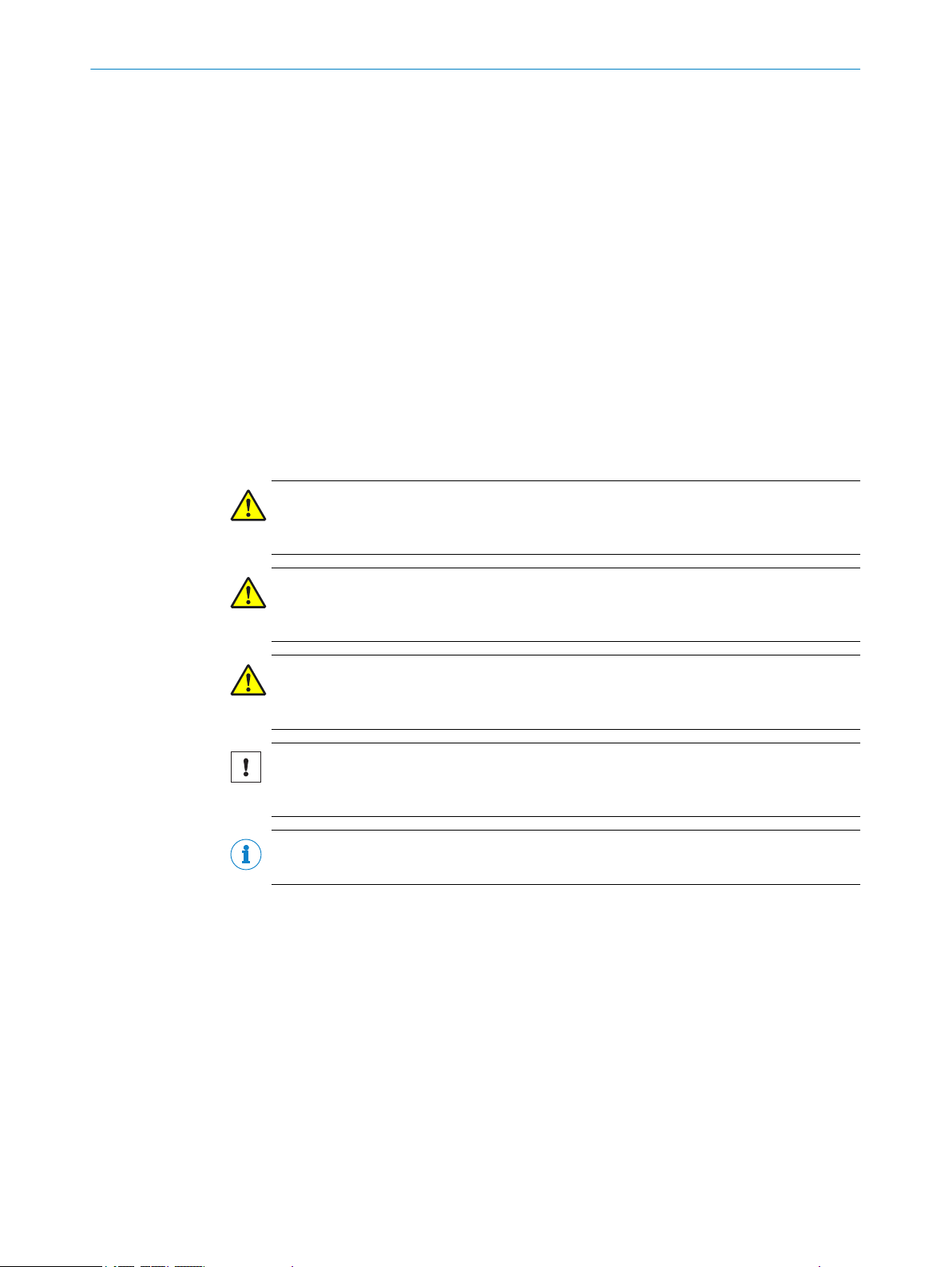
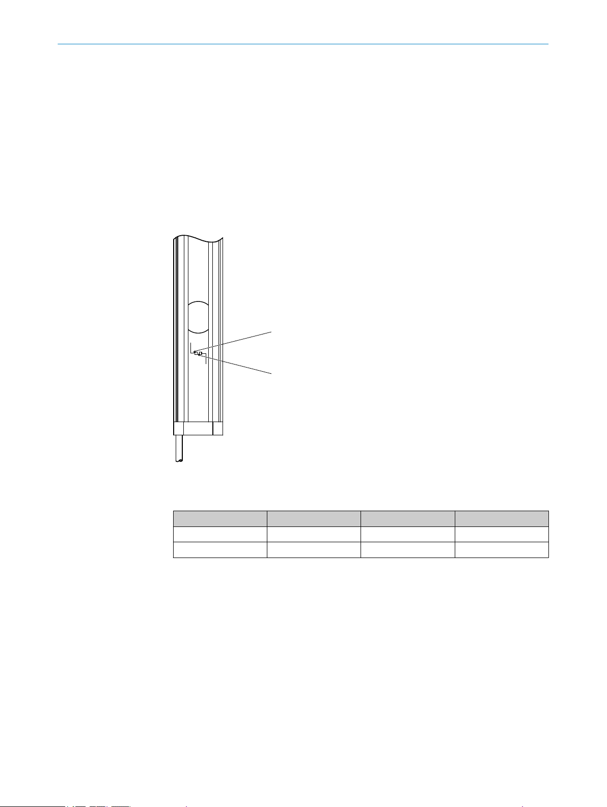
3.2.1 Status indicators
The sender and receiver light emitting diodes indicate the operational status.
Sender indicators
ech‐
Figure 2: Sender indicators
T
wo light emitting diodes on the sender indicate the operational status:
Item LED color Display Labeling
1
2
Yellow Status indicator PWR
Red Fault indicator ERR
Complete overview of the light emitting diode statuses and their meanings: see "Dia
nostic LEDs", page 45.
g‐
12
O PE R AT I NG IN S TR U CT I ON S | deTem2 Core 8014304/ZKD8/2017-03-23 | SICK
Subject to change without notice
Page 13
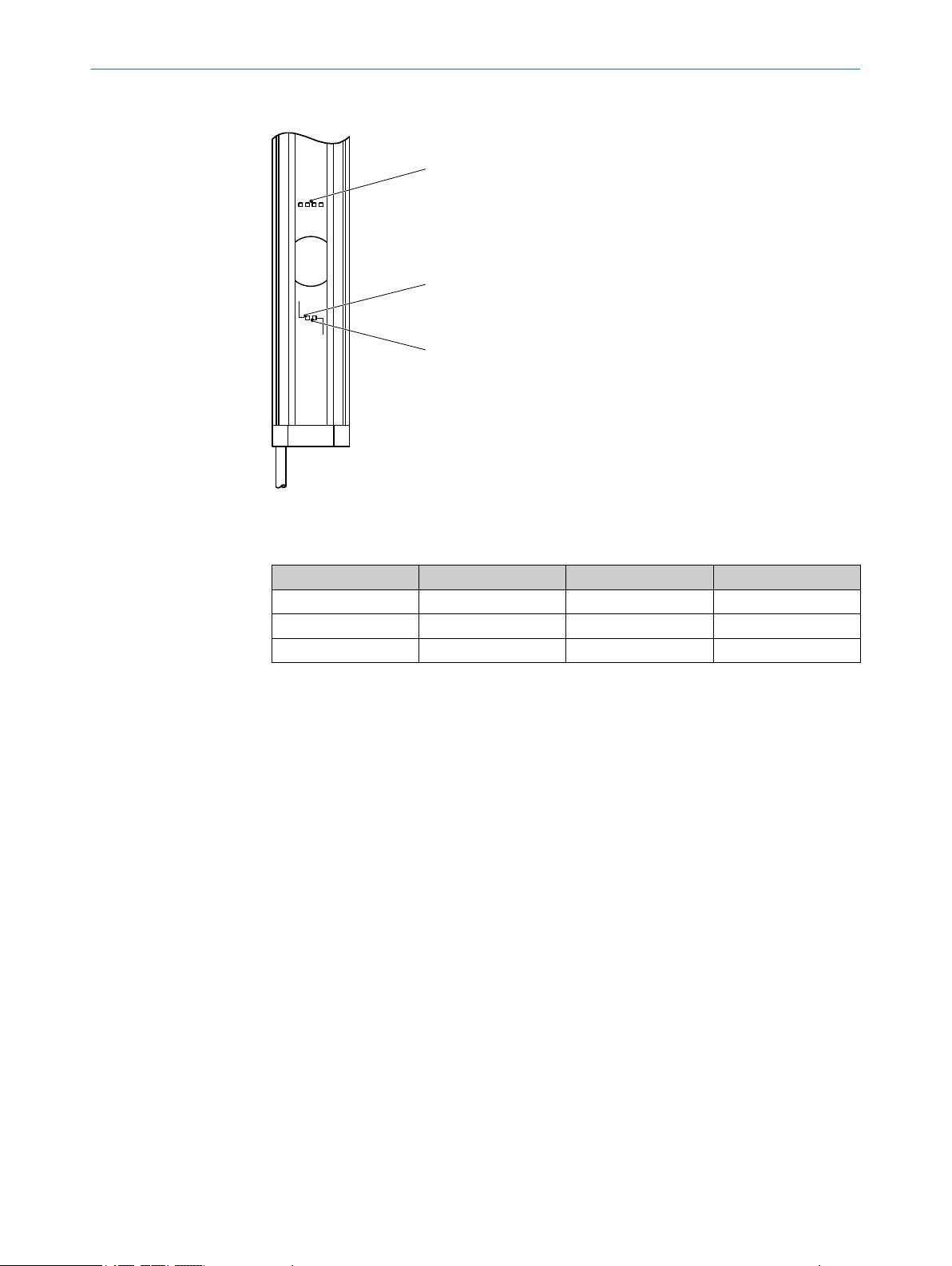
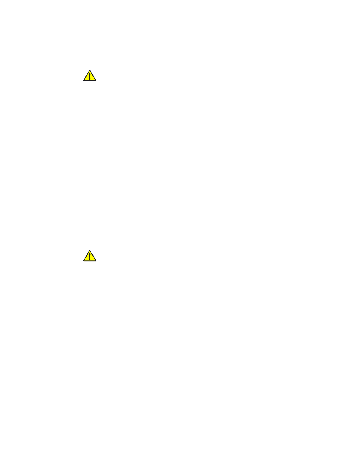
Receiver indicators
ERR
OSSD
1 2 3 4
2
1
3
Figure 3: Receiver indicators
PRODUCT DESCRIPTION 3
S
ix light emitting diodes on the receiver indicate the operational status:
Item LED color Display Labeling
1
2
3
Red/green OSSD status OSSD
Red Fault indicator ERR
Blue Alignment quality 1, 2, 3, 4
The blue alignment quality light emitting diodes in combination with the red flashing
R LED also denote faults.
ER
Complete overview of the light emitting diode statuses and their meanings: see "Diag‐
nostic LEDs", page 45.
8014304/ZKD8/2017-03-23 | SICK O P ER A TI N G I NS T RU C TI O NS | deTem2 Core
Subject to change without notice
13
Page 14
3 P
RODUCT DESCRIPTION
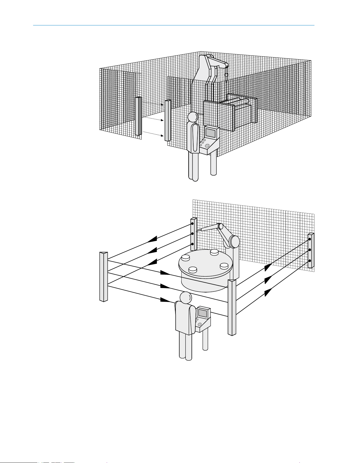
3.3 Example applications
Figure 4: Single-sided access protection
14
Figure 5: Multi-sided access protection
O PE R AT I NG IN S TR U CT I ON S | deTem2 Core 8014304/ZKD8/2017-03-23 | SICK
Subject to change without notice
Page 15
4 Project planning
4.1 Manufacturer of the machine
DANGER
H
azard due to lack of effectiveness of the protective device
Persons and parts of the body to be protected may not be recognized in case of nonobservance.
Use of the multiple light beam safety device requires a risk assessment. Check
b
whether additional protective measures are required.
Comply with the applicable national regulations derived from the application (e.g.,
b
work safety regulations, safety rules, or other relevant safety guidelines).
Do not combine the components of the multiple light beam safety device with
b
components from other multiple light beam safety devices.
Apart from the procedures described in this document, the components of the
b
multiple light beam safety device must not be opened.
The components of the multiple light beam safety device must not be tampered
b
with or changed.
Improper repair of the protective device can lead to a loss of the protective func‐
b
tion. Do not carry out any repairs on the device components.
PROJECT PLANNING 4
4.2 Operating entity of the machine
DANGER
H
azard due to lack of effectiveness of the protective device
Persons and parts of the body to be protected may not be recognized in case of nonobservance.
Changes to the electrical integration of the multiple light beam safety device in the
b
machine control and changes to the mechanical mounting of the multiple light
beam safety device necessitate a new risk assessment. The results of this risk
assessment may require the operating entity of the machine to meet a manufac‐
turer’s obligations.
Apart from the procedures described in this document, the components of the
b
multiple light beam safety device must not be opened.
The components of the multiple light beam safety device must not be tampered
b
with or changed.
Improper repair of the protective device can lead to a loss of the protective func‐
b
tion. Do not carry out any repairs on the device components.
4.3 Design
This chapter contains important information about the design.
Information on the individual steps for mounting the device: see "Mounting", page 25.
8014304/ZKD8/2017-03-23 | SICK O P ER A TI N G I NS T RU C TI O NS | deTem2 Core
Subject to change without notice
15
Page 16
4 P
ROJECT PLANNING
DANGER
azard due to lack of effectiveness of the protective device
H
Persons and parts of the body to be protected may not be recognized in case of non-
observance.
Make sure that the following design requirements are met so that the multiple
b
light beam safety device can fulfill its protective function.
Sender and receiver must be arranged such that persons or parts of the body
°
are reliably detected when they enter the hazardous area.
Ensure that nobody can pass under the lowest light beam, pass over the
°
highest light beam, get between two light beams, or pass by the side of the
protective device.
If people can stay between the protective device and the hazardous point
°
without being detected, check if additional protective measures (e.g., restart
interlock) are required.
DANGER
azard due to lack of effectiveness of the protective device
H
Certain types of light radiation can influence the protective device, e.g., light radiation
from fluorescent lamps with electronic ballast installed in the path of the beam, or
beams from laser pointers directed at the receiver.
If this type of light radiation is present in the environment of the protective device,
b
take additional measures, if required, to ensure that the protective device does not
become dangerous.
4.3.1 Minimum distance from the hazardous point
A minimum distance must be maintained between the multiple light beam safety
vice and the hazardous point. This distance is required to prevent a person or part of
de
the body from reaching the hazardous area before the dangerous state of the machine
state has completed.
DANGER
H
azard due to lack of effectiveness of the protective device
In the case of non-compliance, it is possible that the dangerous state of the machine
may not be stopped or not stopped in a timely manner.
Calculate the required minimum distance for your machine.
b
Mount the multiple light beam safety device taking this calculation into account.
b
Calculating minimum distance
he calculation of the minimum distance is based on international or national stand‐
T
ards and statutory requirements applicable at the place of installation of the machine.
If the minimum distance is calculated according to ISO 13855, then it depends on the
following points:
16
Machine stopping time (time interval between triggering the sensor function and
•
the end of the machine’s dangerous state)
Response time of the protective device, see "Technical data", page 49
•
Approach speed of personnel
•
Type of approach: orthogonal (at right angles)
•
Parameters specified based on the application
•
For the USA (scope of OSHA and ANSI), different regulations may apply, e.g.:
O PE R AT I NG IN S TR U CT I ON S | deTem2 Core 8014304/ZKD8/2017-03-23 | SICK
Subject to change without notice
Page 17
3
4
1
2
PROJECT PLANNING 4
a) Laws: Code of Federal Regulations, Title 29 (CFR29) Part 1910.217
b) St
andards: ANSI B11.19
NOTE
Additional information is available in the ISO 13855 standard and in the Guide for Safe
Machinery.
NOTE
K offers a stopping/run-down time measurement service in many countries.
SIC
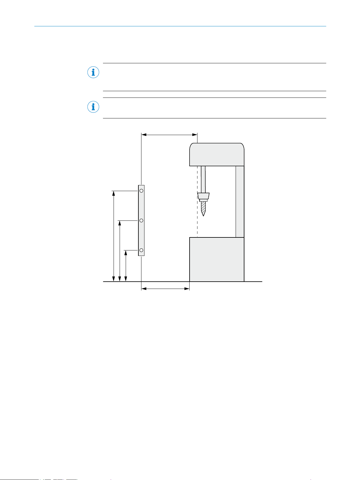
Figure 6: Minimum distance from the hazardous point
Minimum distance S
1
Height of the light beams above ground
2
Hazardous point
3
Depending on the application and distance, persons must be prevented from standing
4
behind the protective device.
Calculation example of the minimum distance S according to ISO 13855
T
he example shows the calculation of the minimum distance for an orthogonal (at right
angles) approach to the multiple light beam safety device. Depending on the applica‐
tion and the ambient conditions, a different calculation may be required (e.g., at a dif‐
ferent angle to the direction of approach or an indirect approach).
1. Calculate S using the following formula:
S = 1,600 mm/s × T + C
where:
S = minimum dis
°
T = machine stopping time + response time of the protective device after
°
interruption in the light path in seconds (s)
8014304/ZKD8/2017-03-23 | SICK O P ER A TI N G I NS T RU C TI O NS | deTem2 Core
Subject to change without notice
tance in millimeters (mm)
17
Page 18
D
a
ROJECT PLANNING
4 P
C = supplement in ac
°
If it is not possible to reach over the protective device: C = 850 mm
•
If it is possible to reach over the protective device, the value CRO must be
•
used for C in accordance with ISO 13855, provided that this is greater
than 850 mm: C ≥ 850 mm and C ≥ C
The reach/approach speed is already included in the formula.
Example calculation: access protection, no danger from reaching over
Mac
hine stopping time = 290 ms
Response time after interruption of the light path = 20 ms
T = 290 ms + 20 ms = 310 ms = 0.31 s
S = 1,600 mm/s × 0.31 s + 850 mm = 1,346 mm
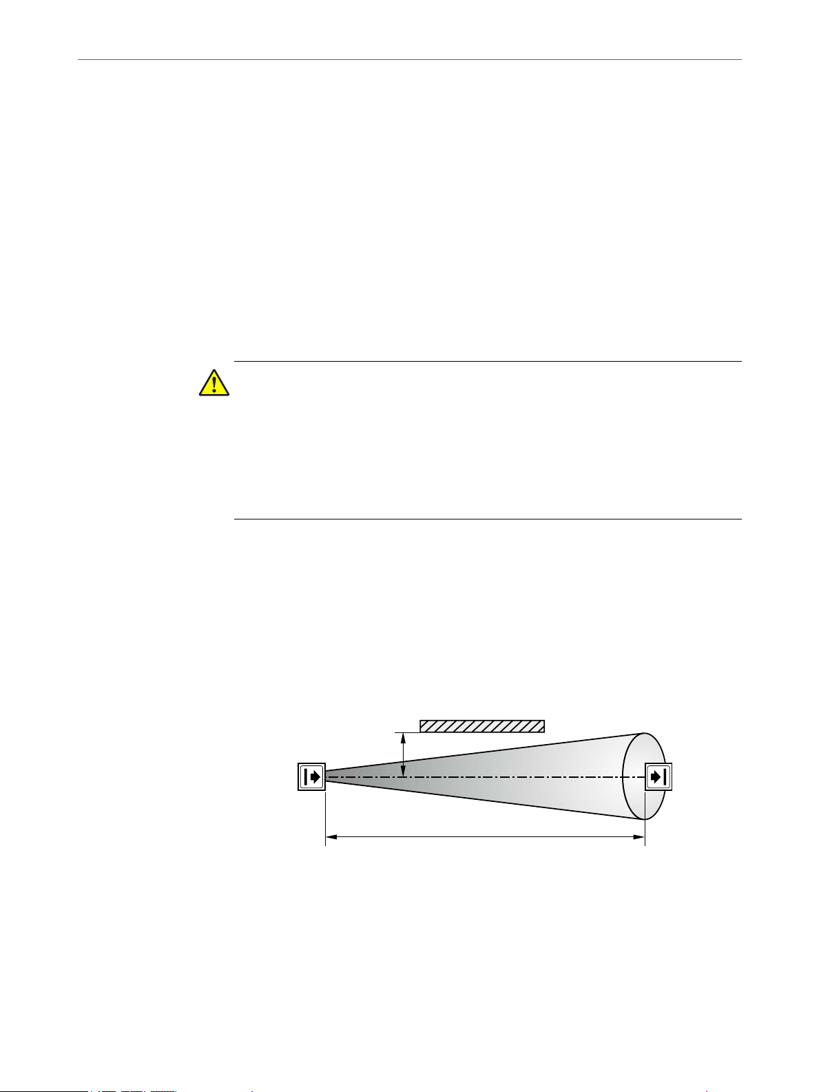
4.3.2 Minimum distance from reflective surfaces
DANGER
azard due to lack of effectiveness of the protective device
H
Reflective surfaces and dispersive media can prevent persons or parts of the body to
be protected from being properly reflected and therefore, they remain undetected.
Make sure that all reflective surfaces and objects maintain a minimum distance
b
from the light beams.
Make sure that no dispersive media (e.g., dust, fog, or smoke) are within the calcu‐
b
lated minimum distance from the light beams.
cordance with ISO 13855:
RO
The light beams from the sender may be deflected by reflective surfaces and dispersive
. This can prevent an object from being detected.
media
Therefore, all reflective surfaces and objects (e.g., material bins, machine table, etc.)
must maintain a minimum distance (a) from the light beams. This minimum distance
(a) must be maintained on all sides of the light beams. This applies in horizontal, verti‐
cal, and diagonal directions as well as at the ends of the multiple light beam safety
device. The same area must be free of dispersive media (e.g., dust, fog, or smoke).
The minimum distance (a) depends on the distance (D) between sender and receiver.
Figure 7: Minimum distance from reflective surfaces
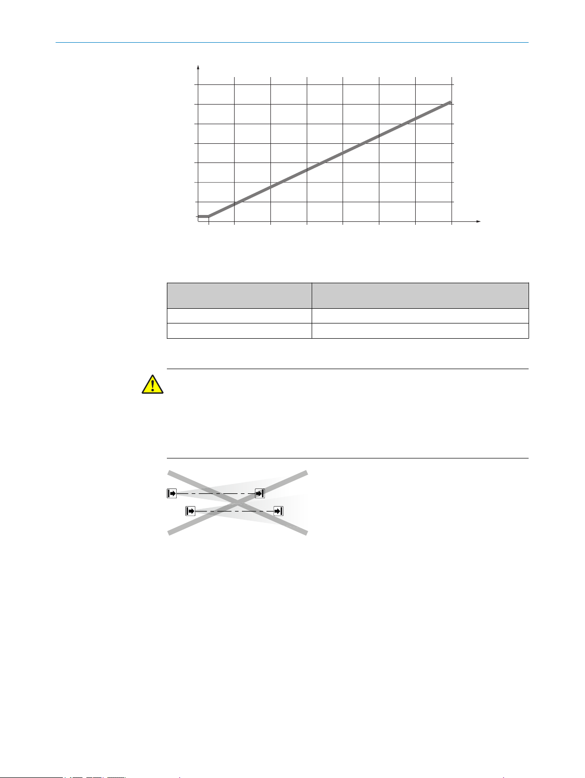
Ho
w to determine the minimum distance from reflective surfaces:
1. Determine the distance between sender and receiver D in meters (m)
2. Read the minimum distance a in millimeters (mm) in the graph or calculate it
based on the respective formula from table 1:
18
O PE R AT I NG IN S TR U CT I ON S | deTem2 Core 8014304/ZKD8/2017-03-23 | SICK
Subject to change without notice
Page 19
10 20 30 40 50 60 70 D/
m
1000
2000
4000
3000
5000
6000
7000
a/mm
262
3
1
2
PROJECT PLANNING 4
Figure 8: Graph, minimum distance from reflective surfaces
T
able 1: Formula for calculating the minimum distance from reflective surfaces
Distance between sender and
r
eceiver D in m
D ≤ 3 m a = 262 mm
D > 3 m a = tan (5°) × 1,000 mm/m × D = 87.49 × 1 mm/m × D
Calculating the minimum distance from reflective surfa‐
ces a in mm
4.3.3 Protection against interference from systems in close proximity to each other
DANGER
H
azard due to lack of effectiveness of the protective device
Systems of multiple light beam safety devices in close proximity to each other can
mutually interfere with each other.
Use suitable measures to prevent interference between systems in close proximity
b
to each other.
Figure 9: Preventing mutual interference from system
and system
2
1
The infrared light beams of the sender of system 1 can interfere with the receiver of
system 2. This can disrupt the protective function of system 2. This would mean that
the operator is at risk.
Avoid such installation situations or take appropriate action, e.g., install optically opa‐
que partitions or reverse the direction of transmission of a system.
8014304/ZKD8/2017-03-23 | SICK O P ER A TI N G I NS T RU C TI O NS | deTem2 Core
Subject to change without notice
19
Page 20
1
2
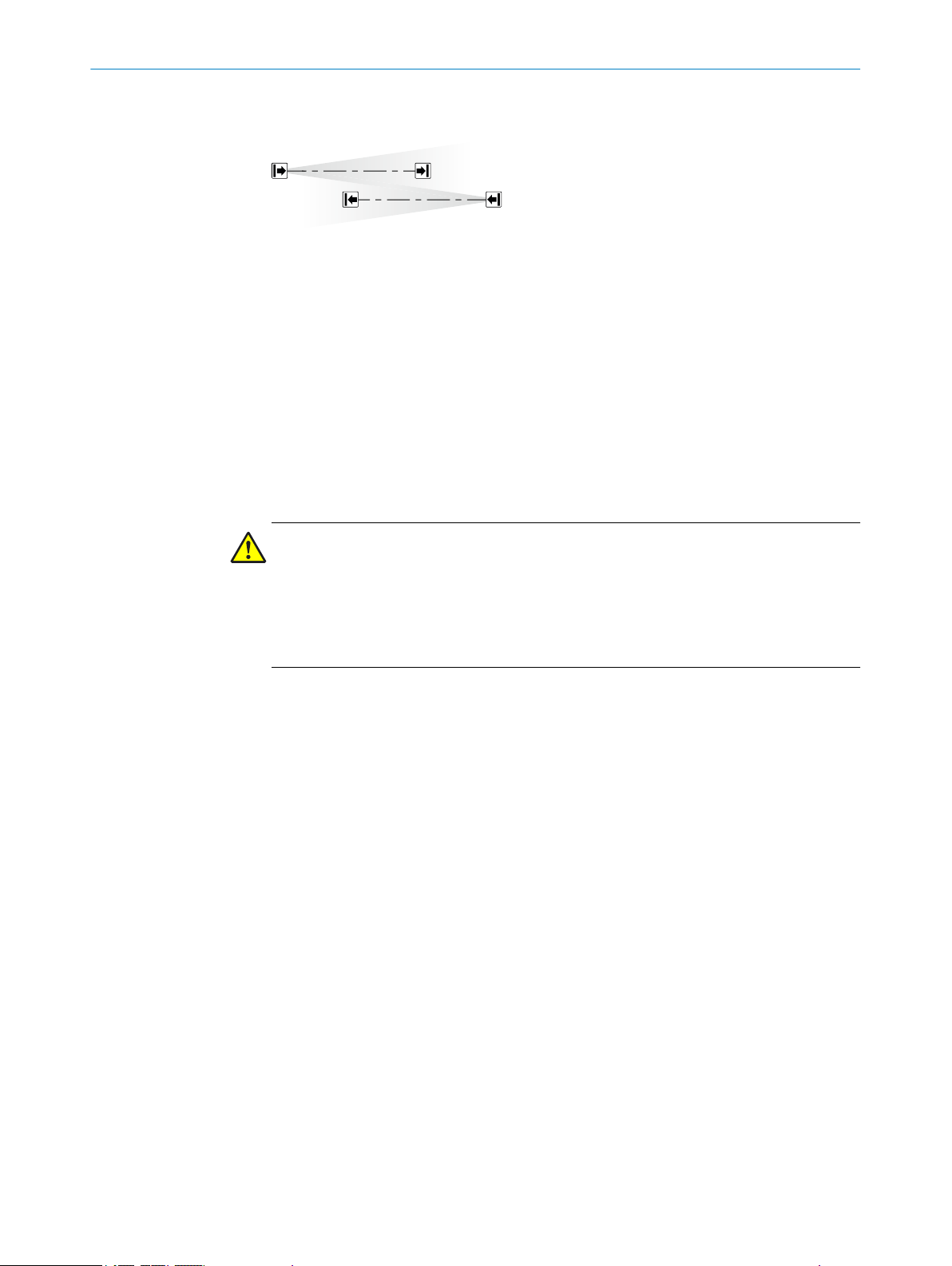
4 PROJECT PLANNING
Reversed direction of transmission
Figure 10: Trouble-free operation due to reversed direction of transmission of system
tem
2
4.4 Integrating into the electrical control
This chapter contains important information about integration in the electrical control.
ormation about the individual steps for electrical installation of the device: see "Elec‐
Inf
trical installation", page 34.
Requirements for use
The output signals of the protective device must be analyzed by downstream controllers
in such a way that the dangerous state of the machine is ended safely. Depending on
the safety concept, the signal is analyzed by, e.g., safety relays or a safety controller.
DANGER
Hazard due to lack of effectiveness of the protective device
In the case of non-compliance, it is possible that the dangerous state of the machine
may not be stopped or not stopped in a timely manner.
Make sure that the following control and electrical requirements are met so that
b
the multiple light beam safety device can fulfill its protective function.
It mus
•
•
•
•
•
•
t be possible to electrically influence the control of the machine.
The electrical control of the machine must meet the requirements of IEC 60204-1.
Depending on the regulations which apply at the place of installation, a restart
interlock may be required. Because the multiple light beam safety device does not
have this function, it must be implemented in the external control if required.
When using a safety controller, different signal levels of both OSSDs must be
detected depending on the regulations which apply at the place of installation or
the required reliability of the safety function. The maximum discrepancy time toler‐
ated by the control must be selected according to the application.
The OSSD1 and OSSD2 output signals must not be connected to each other.
In the machine controller, the signals of both OSSDs must be processed sepa‐
rately.
1
and sys‐
20
O PE R AT I NG IN S TR U CT I ON S | deTem2 Core 8014304/ZKD8/2017-03-23 | SICK
Subject to change without notice
Page 21
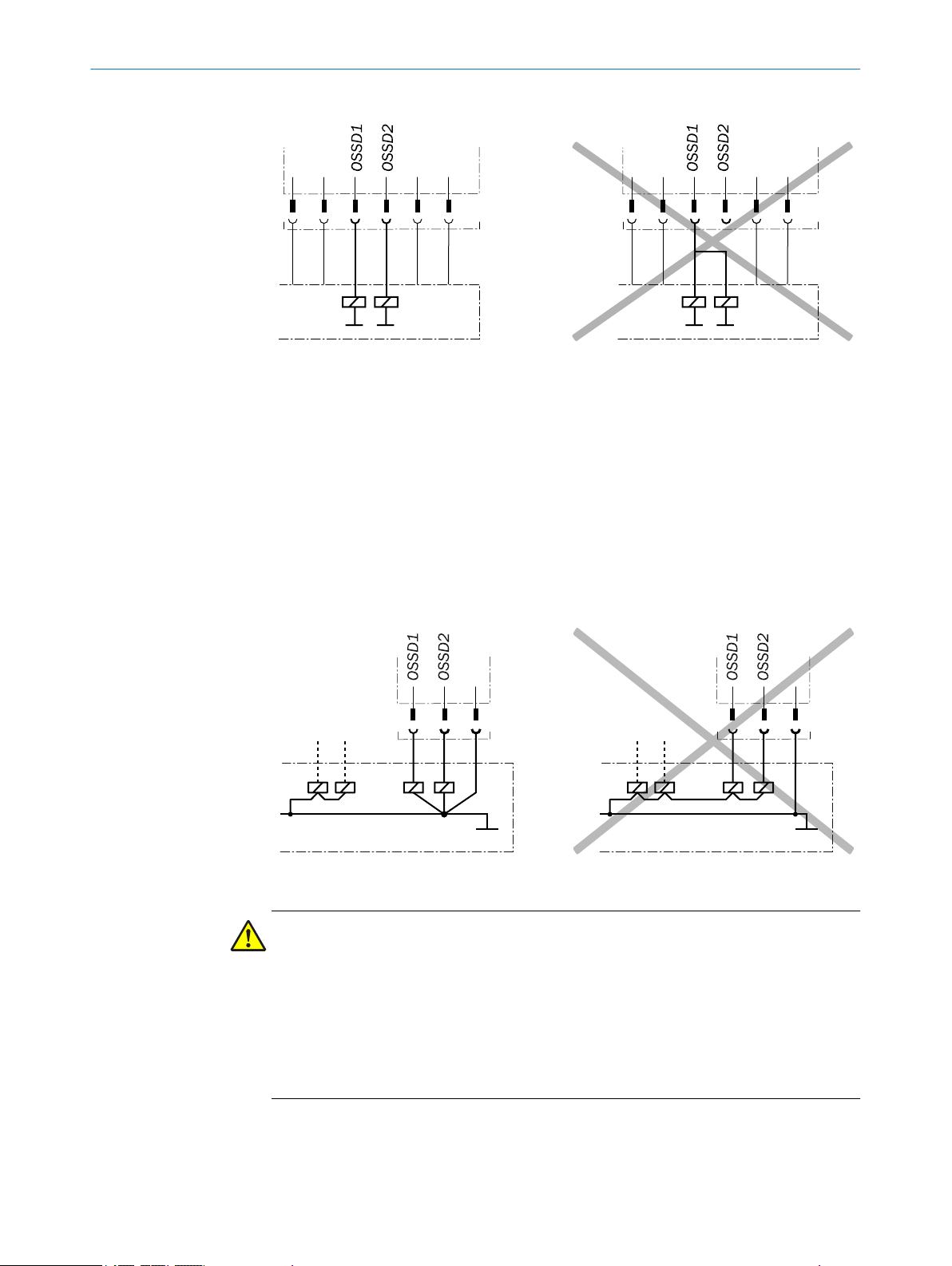
PROJECT PLANNING 4
Figure 11: Dual-channel and isolated connection of OSSD1 and OSSD2
he machine must switch to the safe state at any time if at least one of the two
T
•
OSSDs switches to the OFF state.
Prevent the formation of a potential difference between the load and the protec‐
•
tive device. If you connect loads to the OSSDs (output signal switching devices)
that then also switch if controlled with negative voltage (e.g., electro-mechanical
contactor without reverse polarity protection diode), you must connect the 0 V con‐
nections of these loads and those of the corresponding protective device individu‐
ally and directly to the same 0 V terminal strip. In the event of a fault, this is the
only way to ensure that there can be no potential difference between the 0 V con‐
nections of the loads and those of the corresponding protective device.
Figure 12: No potential difference between load and protective device
DANGER
azard due to lack of effectiveness of the protective device
H
In the case of non-compliance, it is possible that the dangerous state of the machine
may not be stopped or not stopped in a timely manner.
Downstream contactors must be positively guided and monitored depending on appli‐
cable national regulations or required reliability of the safety function.
Make sure that downstream contactors are monitored (external device monitoring,
b
EDM).
ause the multiple light beam safety device does not have integrated external
Bec
b
device monitoring, this must be implemented in the external control, if required.
8014304/ZKD8/2017-03-23 | SICK O P ER A TI N G I NS T RU C TI O NS | deTem2 Core
Subject to change without notice
21
Page 22

4 P
ROJECT PLANNING
Requirements for the electrical control of the machine
Bo
th outputs are short-circuit protected to 24 V DC and 0 V. When the light path is
clear, the OSSDs are in the ON state. When a switch-off condition is present (e.g., inter‐
ruption in the light path), the OSSDs are in the OFF state. In the event of a device fault,
at least one OSSD is in the OFF state.
The multiple light beam safety device complies with the rules for electromagnetic com‐
patibility (EMC) for the industrial sector (Radio Safety Class A). Radio interference can‐
not be ruled out when used in residential areas.
DANGER
Hazard due to lack of effectiveness of the protective device
In the case of non-compliance, it is possible that the dangerous state of the machine
may not be stopped or not stopped in a timely manner.
Make sure that the following control and electrical requirements are met so that
b
the multiple light beam safety device can fulfill its protective function.
The external voltage supply of the multiple light beam safety device must be capa‐
•
ble of buffering brief power failures of 20 ms as specified in IEC 60204-1.
The power supply unit must provide safe isolation according to IEC 61140
•
(SELV/PELV). Suitable power supply units are available as accessories from SICK,
see "Accessories", page 54.
4.4.1 Restart interlock
Depending on the regulations which apply at the place of installation, a restart interlock
ma
y be required.
The restart interlock prevents the machine from automatically starting up, for example
after a protective device has responded while the machine is operating or after chang‐
ing the machine’s operating mode.
Before the machine can be restarted, the operator must reset the restart interlock.
The dangerous state of the machine is brought to an end if the light path is interrupted
and is not re-enabled until the operator presses the reset pushbutton located outside
the hazardous area. The machine can then be restarted.
Depending on the regulations which apply at the place of installation, a restart interlock
must be available if it is possible to stand behind the protective device. Observe IEC
60204-1.
NOTE
ause the multiple light beam safety device does not have an integrated restart inter‐
Bec
lock, this must be implemented in the external control, if required.
4.4.2 External device monitoring (EDM)
The external switching elements (external device monitoring, EDM) must be inspected
in line w
bility of the safety function.
ith the regulations which apply at the place of installation or the required relia‐
22
The external device monitoring (EDM) monitors the status of downstream contactors.
In order to use the external device monitoring, positively guided contactors must be
used to switch off the machine. If the auxiliary contacts of the positively guided contac‐
tors are connected to the external device monitoring, the external device monitoring
checks whether the contactors drop off when the OSSDs are switched off.
O PE R AT I NG IN S TR U CT I ON S | deTem2 Core 8014304/ZKD8/2017-03-23 | SICK
Subject to change without notice
Page 23

4.5 Testing plan
PROJECT PLANNING 4
NOTE
ause the multiple light beam safety device does not have integrated external device
Bec
monitoring, this must be implemented in the external control, if required.
The manufacturer of the machine and the operating entity must define all required
hecks. The definition must be based on the application conditions and the risk assess‐
c
ment and must be documented in a traceable manner.
When defining the check, please note the following:
b
Define the type and execution of the check.
°
Define the frequency of the check.
°
Notify the machine operators of the check and instruct them accordingly.
°
The following checks are often defined in connection with a protective device:
Check during commissioning and modifications
•
Regular check
•
Check during commissioning and modifications
The check must detect if it is possible to enter the hazardous area without being
detected.
The following points are often helpful for the definition of the check:
Does the check have to be completed by quality safety personnel?
•
Can the check be completed by personnel specially qualified and authorized per‐
•
sonnel?
Does the check have to be documented in a traceable manner?
•
Can the check be carried out according to a check list (see "Checklist for initial
•
commissioning and commissioning", page 62)?
Do the machine operators know the function of the protective device?
•
Have the machine operators been trained to work on the machine?
•
Have the machine operators been notified about modifications on the machine?
•
Does the hazardous area to be secured have to be checked with a test rod, see
•
"Test rod check", page 24?
Define all guidelines for the check.
b
Regular check
T
he check must detect if it is possible to enter the hazardous area without being
detected. Such possibilities may exist due to modifications, manipulations or external
influences.
The following points are often helpful for the definition of the check:
Which check must be carried out and how is it carried out?
•
Test rod check, page 24
°
Visual check of the machine and the protective device, page 24
°
How often does the check have to be carried out?
•
Do the machine operators have to be notified of the check and do they need to be
•
instructed accordingly?
Define all guidelines for the check.
b
8014304/ZKD8/2017-03-23 | SICK O P ER A TI N G I NS T RU C TI O NS | deTem2 Core
Subject to change without notice
23
Page 24

4 PROJECT PLANNING
4.5.1 Test rod check
The light beam is covered with an opaque test rod (minimum diameter of 30 mm).
W
hen the light beam is covered, the OSSD LED on the receiver must light up red. The
check is carried out for each light beam and at multiple positions between the sender
and the receiver.
Conducting the test
DANGER
Hazard due to unexpected starting of the machine
Make sure that the dangerous state of the machine is and remains switched off
b
during the check.
Make sure that the outputs of the multiple light beam safety device do not affect
b
the machine during the check.
1. Make sure that the OSSD LED lights up green.
2.
Cover a light beam completely.
✓
The OSSD LED on the receiver lights up red.
3. Enable the light beam.
✓
The OSSD LED on the receiver lights up green.
4. Carry out the check for each light beam.
5. Carry out the check at the following positions:
Immediately in front of the sender
°
In the middle, between the sender and the receiver (or between the deflector
°
mirrors)
Immediately in front of the receiver
°
Directly before and after each deflector mirror (if installed)
°
If the OSSD LED lights up green during the test, even if only briefly, when the light beam
is covered, the machine must be stopped immediately. In this case, the machine and
the protective device must be checked by appropriately qualified safety personnel.
4.5.2 Visual check of the machine and the protective device
The following points are often helpful for the definition of the check:
H
as the machine been retrofitted?
•
Have machine parts been removed?
•
Have modifications been made to the surroundings of the machine?
•
Have the protective device or its parts been dismantled?
•
Is it possible to enter the hazardous area without being detected?
•
Is the protective device damaged?
•
Is the protective device severely contaminated?
•
Is the front screen contaminated, scratched or destroyed?
•
Are there any damaged cables or open cable ends?
•
If one of the points applies, the machine should be shut down immediately. In this case,
the machine and the protective device must be checked by appropriately qualified
safety personnel.
24
O PE R AT I NG IN S TR U CT I ON S | deTem2 Core 8014304/ZKD8/2017-03-23 | SICK
Subject to change without notice
Page 25

5 Mounting
5.1 Safety
MOUNTING 5
For information on the requirements for properly mounting the multiple light beam
afety device, see "Design", page 15.
s
DANGER
D
angerous state of the machine
Make sure that the dangerous state of the machine is (and remains) switched off
b
during mounting, electrical installation, and commissioning.
Make sure that the outputs of the multiple light beam safety device do not affect
b
the machine during mounting, electrical installation, and commissioning.
DANGER
azard due to lack of effectiveness of the protective device
H
The device may become detached or damaged if unsuitable brackets are used or in the
event of excessive vibrations.
Persons and parts of the body to be protected may not be recognized in case of non-
observance.
5.2 Unpacking
Only use brackets recommended by SICK for mounting.
b
Take appropriate measures for vibration dampening if the vibration and shock
b
requirements are above the values and test conditions specified in the data sheet,
see "Technical data", page 49.
DANGER
Hazard due to lack of effectiveness of the protective device
Persons and parts of the body to be protected may not be recognized in case of non-
observance.
Do not carry out any repairs to the device components.
b
Do not make any changes to or tamper with the device components.
b
With the exception of the procedures described in this document, the device com‐
b
ponents must not be opened.
NOTE
Mount the device in the following order.
k the integrity of the components and that all parts are presentsee "Scope of
Chec
b
delivery", page 53.
Please contact your respective SICK subsidiary should you have any complaints.
b
5.3 Mounting
The QuickFix bracket or the FlexFix bracket is used to mount the sender and receiver. In
y cases, the QuickFix bracket is enough for mounting. The FlexFix bracket makes it
man
possible to rotate the sender and receiver around the axis of the device and to align it
accurately.
8014304/ZKD8/2017-03-23 | SICK O P ER A TI N G I NS T RU C TI O NS | deTem2 Core
Subject to change without notice
25
Page 26

5 MOUN
TING
DANGER
azard due to lack of effectiveness of the protective device
H
Persons or parts of the body to be protected may not be recognized or not recognized in
time in case of non-observance.
Take account of the minimum distances calculated for the machine: see "Mini‐
b
mum distance from the hazardous point", page 16, see "Minimum distance from
reflective surfaces", page 18.
Mount multiple light beam safety devices such that nobody can pass under the
b
lowest light beam, pass over the highest light beam, get between two light beams,
or pass by the side of the protective device.
NOTE
ead this section in full before mounting the brackets.
R
b
Read the information on aligning the sender and receiver, see "Aligning the sender
b
and receiver", page 37
Mounting instructions
DANGER
H
azard due to lack of effectiveness of the protective device
Persons and parts of the body to be protected may not be recognized in case of nonobservance.
The end with the cable connection must point in the same direction for the sender
b
and receiver.
26
Figure 13: Sender and receiver must not be installed at 180° rotated relative to each other
O PE R AT I NG IN S TR U CT I ON S | deTem2 Core 8014304/ZKD8/2017-03-23 | SICK
Subject to change without notice
Page 27

MOUNTING 5
Mount t
b
Mount the sender and receiver at the same height. For minor adjustments when
b
aligning, the sender and receiver can be adjusted longitudinally in the brackets,
see "Alignment with the QuickFix bracket", page 38, see "Alignment with the
FlexFix bracket or with the upgrade bracket", page 39.
If possible, mount the top bracket at a height such that the offset in the multiple
b
light beam safety device housing is resting on the bracket. This ensures that the
multiple light beam safety device will not slip down during mounting.
Tighten the screws used to mount the bracket to a torque of 5 Nm to 6 Nm.
b
Tighten the screws used to secure the multiple light beam safety device in the
bracket to a torque of 2.5 Nm to 3 Nm. Higher torques can damage the bracket,
while lower torques do not provide adequate fixation to prevent the multiple light
beam safety device from moving.
When mounting, make sure that sender and receiver are aligned correctly. The
b
optics of sender and receiver must be located opposite one another.
If necessary, use a spirit level to check that the components are parallel.
b
5.3.1 Mounting the QuickFix bracket
The sender and receiver are each mounted with two QuickFix brackets.
T
he two mounting surfaces for the brackets of the sender or receiver must be parallel
and lie in the same plane.
Mount QuickFix bracket on a machine or profile frame
he sender and receiver on a level surface.
T
he QuickFix bracket consists of two parts, which are pushed into each other. An M5
screw is used to join both parts and to clamp the housing (sender or receiver).
Mounting can be carried out in two ways:
On the side
•
With the M5 screw through the QuickFix bracket to the machine or profile
°
frame. A screw nut or threaded hole is required on the machine or profile
frame.
With the M5 screw through the machine or profile frame to the QuickFix
°
bracket. A screw nut is required for each QuickFix bracket.
On the back
•
With the M5 screw through the QuickFix bracket to the machine or profile
°
frame. A screw nut or threaded hole is required on the machine or profile
frame.
When choosing the length of the M5 screw (hexagon head or cylinder head screw),
b
consider the QuickFix bracket and the machine or profile frame.
CAUTION
Ris
k of injury from protruding screw thread
When mounting through the machine or profile frame to the QuickFix bracket, the M5
screw can present an injury risk if too long.
Select an appropriate screw length to prevent any risk of injury from an overrun.
b
8014304/ZKD8/2017-03-23 | SICK O P ER A TI N G I NS T RU C TI O NS | deTem2 Core
Subject to change without notice
27
Page 28

1 2
5 MOUN
TING
Figure 14: Mounting the QuickFix bracket to a profile
Mounting on the side
1
Mounting on the back
2
NOTE
T
he QuickFix bracket has cable routing. Depending on the installation, the cable routing
can make mounting easier.
5.3.2 Mounting the FlexFix bracket
In the FlexFix bracket, the sender and receiver can be rotated ± 15° around their longi‐
t
udinal axis.
2 FlexFix brackets are used to mount the sender and receiver.
As a rule, each FlexFix bracket is mounted to the mounting surface with 2 screws. If the
vibration and shock requirements permit it, a FlexFix bracket can also be mounted with
just one screw.
NOTICE
T
he housing of the multiple light beam safety device can become scratched if the screw
heads protrude when the FlexFix brackets are mounted on the back.
Avoid this by taking one of the following measures:
Use flat head screws.
b
If using cylinder head screws, use two screws per bracket and no washers.
b
Mount FlexFix bracket on the side of a machine or profile frame
Mount
ing can be carried out in two ways:
28
On the side
•
With the M5 screw through the FlexFix bracket to the machine or profile
°
frame. A screw nut or threaded hole is required on the machine or profile
frame.
On the back
•
With the M5 screw through the FlexFix bracket to the machine or profile
°
frame. A screw nut or threaded hole is required on the machine or profile
frame.
O PE R AT I NG IN S TR U CT I ON S | deTem2 Core 8014304/ZKD8/2017-03-23 | SICK
Subject to change without notice
Page 29

1 2
Figure 15: Mount FlexFix brackets to a profile frame
Mounting on the side
1
Mounting on the back
2
MOUNTING 5
1. After mounting the FlexFix brackets, screw the sender and receiver into the FlexFix
br
ackets from the front and align the sender and receiver, see "Aligning the sender
and receiver", page 37.
NOTE
T
he multiple light beam safety device can only be screwed in when both FlexFix brack‐
ets are in alignment.
Recommendation:
1. Only hand-tighten the screws on the FlexFix brackets at first.
2. Align the two FlexFix brackets. To do this, place a straightedge or spirit level, for
example, on the screw mounting surfaces of the FlexFix brackets that are not
being used.
3. Tighten the screws.
8014304/ZKD8/2017-03-23 | SICK O P ER A TI N G I NS T RU C TI O NS | deTem2 Core
Subject to change without notice
29
Page 30

5 MOUNTING
30
Figure 16: Inserting the multiple light beam safety device in the FlexFix brackets
2.
Use the M5 screw to fix the position of the sender and receiver in the FlexFix
bracket.
Mount FlexFix bracket to the back of a device column
The FlexFix bracket can be mounted in the device column using sliding nuts.
If you wish to mount the sender and receiver in the center of the device column, use
washers between the FlexFix brackets and the device column.
NOTE
he FlexFix mounting kit (part number 2073543) contains two FlexFix brackets, one
T
alignment tool, and the required screws, sliding nuts, and washers, see "Accessories",
page 54.
O PE R AT I NG IN S TR U CT I ON S | deTem2 Core 8014304/ZKD8/2017-03-23 | SICK
Subject to change without notice
Page 31

MOUNTING 5
1. After mounting the FlexFix brackets, screw the sender and receiver into the FlexFix
br
ackets from the front and align the sender and receiver, see "Aligning the sender
and receiver", page 37.
2. Use the M5 screw to fix the position of the sender and receiver in the FlexFix
bracket.
Figure 17: Mounting the FlexFix bracket to a device column (accessory)
5.3.3 Mounting the optional upgrade bracket
If an existing M2000 multiple light beam safety device is mounted with a swivel mount
br
acket or with a side bracket, it can be replaced with a deTem2 Core multiple light
beam safety device using an upgrade bracket. There is no need to drill new holes, since
the existing ones can be used for the upgrade bracket.
Mount the new multiple light beam safety device so that the light beams are cor‐
b
rectly positioned.
Use one of the following installation versions independent of the existing mounting
b
situation:
To replace a swivel mount bracket (part number 2019649, 2019659, or
°
2030510): installation version A or B
To replace a side bracket (part number 2019506): installation version C
°
8014304/ZKD8/2017-03-23 | SICK O P ER A TI N G I NS T RU C TI O NS | deTem2 Core
Subject to change without notice
31
Page 32

M4000, M2000
deTem4, deTem2
A
A
2071021
2019649
2019659
2030510
M4000, M2000
deTem4, deTem2
B
B
2071021
2019649
2019659
2030510
5 MOUN
TING
Figure 18: Upgrade bracket, installation version A
32
Figure 19: Upgrade bracket, installation version B
O PE R AT I NG IN S TR U CT I ON S | deTem2 Core 8014304/ZKD8/2017-03-23 | SICK
Subject to change without notice
Page 33

deTem4, deTem2
≥ 282
(141)
M4000, M2000
(141)
2071021
2019506
MOUNTING 5
Figure 20: Upgrade bracket, installation version C
8014304/ZKD8/2017-03-23 | SICK O P ER A TI N G I NS T RU C TI O NS | deTem2 Core
Subject to change without notice
33
Page 34

6 ELECTRICAL INSTALLATION
6 Electrical installation
6.1 Safety
Information on the requirements that must be met for safe integration of the multiple
ght beam safety device in the control and electronics of the machine: see "Integrating
li
into the electrical control", page 20.
Mounting should be completed before electrical installation.
DANGER
H
azard due to electrical voltage
Hazard due to unexpected starting of the machine
Make sure that the machine is (and remains) disconnected from the power supply
b
during the electrical installation.
Make sure that the dangerous state of the machine is (and remains) switched off
b
during electrical installation.
Make sure that the outputs of the multiple light beam safety device do not affect
b
the machine during electrical installation.
Only use an appropriate voltage supply, see "Technical data", page 49.
b
DANGER
H
azard due to lack of effectiveness of the protective device
The dangerous state may not be stopped in the event of non-compliance.
Always connect the two OSSDs separately. The two OSSDs must not be connected
b
to each other.
Connect the OSSDs such that the machine controller processes both signals sepa‐
b
rately.
Figure 21: Dual-channel and isolated connection of OSSD1 and OSSD2
34
DANGER
H
azard due to lack of effectiveness of the protective device
The dangerous state may not be stopped in the event of non-compliance.
Prevent the formation of a potential difference between the load and the protec‐
b
tive device.
O PE R AT I NG IN S TR U CT I ON S | deTem2 Core 8014304/ZKD8/2017-03-23 | SICK
Subject to change without notice
Page 35

12
3 4
5
ELECTRICAL INSTALLATION 6
event the formation of a potential difference between the load and the protec‐
Pr
•
tive device. If you connect loads to the OSSDs (output signal switching devices)
that then also switch if controlled with negative voltage (e.g., electro-mechanical
contactor without reverse polarity protection diode), you must connect the 0 V con‐
nections of these loads and those of the corresponding protective device individu‐
ally and directly to the same 0 V terminal strip. In the event of a fault, this is the
only way to ensure that there can be no potential difference between the 0 V con‐
nections of the loads and those of the corresponding protective device.
Figure 22: No potential difference between load and protective device
6.2 System connection (M12, 5-pin)
Figure 23: System connection (M12, 5-pin)
Table 2: System connection pin assignment (M12, 5-pin)
Pin Wire color
1 Brown +24 V DC (input voltage
2 White Reserved OSSD1 (output signal
3 Blue 0 V DC (input voltage sup‐
4 Black Reserved OSSD2 (output signal
5 Gray Not assigned Not assigned
1)
Applies to the extension cables recommended as accessories.
1)
ender r Receiver
s S
+24 V DC (input voltage
suppl
ply)
y)
supply)
switching device 1)
0 V DC (input voltage sup‐
ply)
witching device 2)
s
Connection diagrams for the electrical installation: see "Int
egrating into the electrical
control", page 20.
6.3 System connection via connection cable (M12, 5-pin to 8-pin)
An optional connection cable is available to connect the 5-pin system connection to an
e
xisting 8-pin female connector. The connection cable can be used to replace an exist‐
8014304/ZKD8/2017-03-23 | SICK O P ER A TI N G I NS T RU C TI O NS | deTem2 Core
Subject to change without notice
ing M2000 multiple light beam safety device with a deTem2 Core multiple light beam
safety device, without having to route new cables.
35
Page 36

OMMISSIONING
7 C
7 Commissioning
7.1 Safety
DANGER
H
azard due to lack of effectiveness of the protective device
When changes are made to the machine, the effectiveness of the protective device may
be affected unintentionally.
After every change to the machine and changes to the integration or operational
b
and secondary conditions of the multiple light beam safety device, check the pro‐
tective device for effectiveness and recommission as specified in this chapter.
DANGER
D
angerous state of the machine
Make sure that the dangerous state of the machine is (and remains) switched off
b
during mounting, electrical installation, and commissioning.
Make sure that the outputs of the multiple light beam safety device do not affect
b
the machine during mounting, electrical installation, and commissioning.
DANGER
azard due to lack of effectiveness of the protective device
H
Before commissioning the machine, make sure that the machine is first checked
b
and released by qualified safety personnel.
Only operate the machine with a perfectly functioning protective device.
b
DANGER
azard due to lack of effectiveness of the protective device
H
Persons and parts of the body to be protected may not be recognized in case of non-
observance.
Make sure that the optical properties of the front screens of the sender and
b
receiver are not changed, e.g., by:
Beading water, mist, frost, or ice formation. If applicable, remove films or
°
other types of contamination, disconnect the voltage supply of the receiver
and then switch it back on.
Scratches or damage. Replace the device whose front screen is scratched or
°
damaged.
Make sure that all reflective surfaces and objects maintain a minimum distance
b
from the light beams, see "Minimum distance from reflective surfaces", page 18.
Make sure that no dispersive media (e.g., dust, fog, or smoke) are within the calcu‐
b
lated minimum distance from the light beams.
7.2 Overview
36
O PE R AT I NG IN S TR U CT I ON S | deTem2 Core 8014304/ZKD8/2017-03-23 | SICK
The mounting and electrical installation work must be completed before commissioning
s described in the following chapters:
a
"Design", page 15
•
"Integrating into the electrical control", page 20
•
"Mounting", page 25
•
"Electrical installation", page 34
•
Subject to change without notice
Page 37

7.3 Switching on
After switching on, the sender and receiver initialize. All light emitting diodes of the
sender and r
ment quality using four blue light emitting diodes. Once the multiple light beam safety
device is aligned (OSSD LED: green), the alignment display switches off after a certain
period of time, and only the PWR LED of the sender and the OSSD LED of the receiver
continue to light up.
In the event of a fault, the red fault light emitting diode flashes on the respective
device. The red fault light emitting diode in combination with the blue light emitting
diodes show the cause of the fault on the side of the receiver, see "Troubleshooting",
page 45.
eceiver briefly light up. After initialization, the receiver displays the align‐
7.4 Aligning the sender and receiver
After mounting and electrical installation, the sender and receiver must be aligned with
e
ach other.
DANGER
D
angerous state of the machine
COMMISSIONING 7
Make sure that the dangerous state of the machine is (and remains) switched off
b
during the alignment process.
Make sure that the outputs of the multiple light beam safety device do not affect
b
the machine during the alignment process.
Please also observe the following sections:
gnment with the QuickFix bracket, page 38
Ali
•
Alignment with the FlexFix bracket or with the upgrade bracket, page 39
•
Indication of the alignment quality, page 40
•
Aligning the sender and receiver with one another
1.
Ensure that the sender and receiver are mounted correctly and, in particular, at
the right height.
2. Ensure that the multiple light beam safety device can rotate in the bracket. If
required, loosen the fixing screws a little.
3. Switch on the voltage supply for the multiple light beam safety device.
4. Roughly align the sender with the receiver by rotating it.
5. Align the receiver with the sender. To do this, rotate the receiver so that as many
blue alignment quality light emitting diodes as possible light up on the receiver.
6. If required, align the sender more precisely to the receiver so that as many align‐
ment quality light emitting diodes as possible light up on the receiver.
7. If required, align the receiver more precisely to the sender so that as many align‐
ment quality light emitting diodes as possible light up on the receiver.
8. When at least three (preferably four) alignment quality light emitting diodes light
up on the receiver, fasten the components in the brackets. Torque: 2.5 to 3 Nm.
9. Switch the voltage supply off and then on again.
10. Check the alignment quality light emitting diodes to make sure that the compo‐
nents are still correctly aligned with each other.
Aligning the sender, receiver, and deflector mirror
1. Ensure that the sender and receiver are mounted correctly and, in particular, at
the right height.
2. Ensure that the multiple light beam safety device can rotate in the bracket. If
required, loosen the fixing screws a little.
8014304/ZKD8/2017-03-23 | SICK O P ER A TI N G I NS T RU C TI O NS | deTem2 Core
Subject to change without notice
37
Page 38

OMMISSIONING
7 C
3. Switch on the voltage supply for the multiple light beam safety device.
4.
Place the laser alignment aid near to the bottom light beam on the sender.
5. Rotate the sender and adjust the height of the mirror column so that the laser
beam hits the bottom mirror of the first mirror column.
The laser beam should hit the center of the mirror horizontally.
°
The laser beam should hit the mirror vertically with the same deviation from
°
the center of the mirror that the laser of the laser alignment aid has from the
bottom light beam.
6. Fix the sender in the brackets. Torque: 2.5 to 3 Nm.
The alignment may move a little when the screws are tightened. However, do
°
not correct the setting.
7. Place the laser alignment aid near to the bottom light beam on the receiver.
8. Rotate the receiver so that the laser beam hits the bottom mirror of the first mirror
column.
The laser beam should hit the center of the mirror horizontally.
°
The laser beam should hit the mirror vertically with the same deviation from
°
the center of the mirror that the laser of the laser alignment aid has from the
bottom light beam.
9. Rotate the bottom mirror of the first mirror column so that the laser beam hits the
bottom mirror of the second mirror column. If no other mirror column is available,
the laser beam must hit the bottom beam of the sender.
10. Repeat step 9 for the subsequent mirror columns, until the laser beam hits the
sender.
11. Perform steps 7 to 10 for all beams from the bottom to the top.
Align each individual mirror separately.
°
When deflecting using mirrors, the angle of incidence is the same as the
°
emergence angle. Rotating the mirror slightly results in a deflection that is
twice as great.
Only a part of the original ray beam is ever transmitted via deflector mirrors.
°
The alignment tolerance is reduced with each additional deflection.
12. Switch the voltage supply off and then on again.
13. Check the alignment quality light emitting diodes to make sure that the compo‐
nents are still correctly aligned with each other.
38
NOTE
hree blue alignment quality light emitting diodes light up, alignment is good and
Once t
availability is stable.
Please note that objects between the sender and receiver (e.g., hand, tool, AR60
optional laser alignment aid) may impair the function of the alignment quality light emit‐
ting diodes. Remove all objects from this area to allow the alignment quality to be
assessed.
NOTE
he AR60 optional laser alignment aid can be used for alignment, see "Accessories",
T
page 54.
To ensure that the indication of the alignment quality is not impaired, place the AR60
optional laser alignment aid with the adapter between the light beams of the multiple
light beam safety device.
Alignment with the QuickFix bracket
Y
ou have the following adjustment options with the QuickFix bracket:
Adjust vertically (H)
•
O PE R AT I NG IN S TR U CT I ON S | deTem2 Core 8014304/ZKD8/2017-03-23 | SICK
Subject to change without notice
Page 39

H
≤
L /4
L
≤ L /4
COMMISSIONING 7
Figure 24: QuickFix bracket: adjust vertically
NOTE
If t
he alignment cannot be adjusted with the QuickFix bracket, use the optional FlexFix
bracket.
Alignment with the FlexFix bracket or with the upgrade bracket
ou have the following adjustment options with the FlexFix bracket or the upgrade
Y
bracket:
Adjust vertically (H)
•
Rotate (± 15°)
•
8014304/ZKD8/2017-03-23 | SICK O P ER A TI N G I NS T RU C TI O NS | deTem2 Core
Subject to change without notice
39
Page 40

H
≤ L /4
L
≤ L /4
+/–15°
7 COMMISSIONING
Figure 25: FlexFix bracket: adjust vertically/rotate
Indication of the alignment quality
T
able 3: Indication of the alignment quality
Indication Meaning
Alignment qual‐
it
y light emitting
diodes
No light emitting
diode lights up
1 light emitting
diode lights up
2 light emitting
s light up
diode
2 light emitting
diodes light up
3 light emitting
diodes light up
4 light emitting
s light up
diode
1)
If the light path is very long, there is a possibility that all four alignment quality light emitting diodes will
not light up even when alignment is good.
OSSD LED
Red Alignment is insufficient or a light beam is interrupted at
least partially. The receiver cannot synchronize with the
sender.
Red Alignment is insufficient or a light beam is interrupted at
least partially.
Red Alignment is insufficient or a light beam is interrupted at
least partially.
Green Alignment is not yet sufficient for stable availability.
Green Alignment is good, stable availability.
1)
Green Alignment is very good.
40
O PE R AT I NG IN S TR U CT I ON S | deTem2 Core 8014304/ZKD8/2017-03-23 | SICK
Subject to change without notice
Page 41

COMMISSIONING 7
NOTE
hree blue alignment quality light emitting diodes light up, alignment is good and
Once t
availability is stable.
Please note that objects between the sender and receiver (e.g., hand, tool, AR60
optional laser alignment aid) may impair the function of the alignment quality light emit‐
ting diodes. Remove all objects from this area to allow the alignment quality to be
assessed.
Complete overview of the light emitting diode statuses and their meanings: see "Dia
nostic LEDs", page 45.
7.5 Check during commissioning and modifications
The check must detect if it is possible to enter the hazardous area without being
de
tected.
C
arry out the checks according to the instructions from the manufacturer of the
b
machine and from the operating entity.
g‐
8014304/ZKD8/2017-03-23 | SICK O P ER A TI N G I NS T RU C TI O NS | deTem2 Core
Subject to change without notice
41
Page 42

8 O
PERATION
8 Operation
8.1 Safety
DANGER
H
azard due to lack of effectiveness of the protective device
Persons and parts of the body to be protected may not be recognized in case of nonobservance.
Maintenance work, alignment work, fault diagnoses, and any changes to the inte‐
b
gration of the protective device in the machine must only be carried out by quali‐
fied personnel.
The effectiveness of the protective device must be checked following such work.
b
DANGER
H
azard due to lack of effectiveness of the protective device
Persons and parts of the body to be protected may not be recognized in case of nonobservance.
Make sure that the optical properties of the front screens of the sender and
b
receiver are not changed, e.g., by:
Beading water, mist, frost, or ice formation. If applicable, remove films or
°
other types of contamination, disconnect the voltage supply of the receiver
and then switch it back on.
Scratches or damage. Replace the device whose front screen is scratched or
°
damaged.
Make sure that all reflective surfaces and objects maintain a minimum distance
b
from the light beams, see "Minimum distance from reflective surfaces", page 18.
Make sure that no dispersive media (e.g., dust, fog, or smoke) are within the calcu‐
b
lated minimum distance from the light beams.
NOTE
This document does not provide instructions for operating the machine in which the
multiple light beam safety device is integrated.
8.2 Regular thorough check
The check must detect if it is possible to enter the hazardous area without being
tected. Such possibilities may exist due to modifications, manipulations or external
de
influences.
C
arry out the checks according to the instructions from the manufacturer of the
b
machine and from the operating entity.
42
O PE R AT I NG IN S TR U CT I ON S | deTem2 Core 8014304/ZKD8/2017-03-23 | SICK
Subject to change without notice
Page 43

9 Maintenance
9.1 Safety
DANGER
H
azard due to lack of effectiveness of the protective device
Persons and parts of the body to be protected may not be recognized in case of nonobservance.
Do not carry out any repairs to the device components.
b
Do not make any changes to or tamper with the device components.
b
With the exception of the procedures described in this document, the device com‐
b
ponents must not be opened.
9.2 Regular cleaning
DANGER
H
azard due to lack of effectiveness of the protective device
Persons and parts of the body to be protected may not be recognized in case of nonobservance.
MAINTENANCE 9
Regularly check the degree of contamination on all components based on the
b
application conditions.
Observe the information concerning test rod testing, see "Test rod check",
b
page 24.
Depending on the ambient conditions of the multiple light beam safety device, the front
eens must be cleaned regularly and in the event of contamination. Static charges
scr
can cause dust particles to be attracted to the front screen.
The weld spark guard and deflector mirrors must be cleaned regularly and in the event
of contamination.
DANGER
azard due to lack of effectiveness of the protective device
H
Persons and parts of the body to be protected may not be recognized in case of non-
observance.
Make sure that the optical properties of the front screens of the sender and
b
receiver are not changed, e.g., by:
Beading water, mist, frost, or ice formation. If applicable, remove films or
°
other types of contamination, disconnect the voltage supply of the receiver
and then switch it back on.
Scratches or damage. Replace the device whose front screen is scratched or
°
damaged.
Make sure that all reflective surfaces and objects maintain a minimum distance
b
from the light beams, see "Minimum distance from reflective surfaces", page 18.
Make sure that no dispersive media (e.g., dust, fog, or smoke) are within the calcu‐
b
lated minimum distance from the light beams.
8014304/ZKD8/2017-03-23 | SICK O P ER A TI N G I NS T RU C TI O NS | deTem2 Core
Subject to change without notice
43
Page 44

9 MAINTENANCE
DANGER
azard due to unexpected starting of the machine
H
Make sure that the dangerous state of the machine is and remains switched off
b
during the cleaning.
Make sure that the outputs of the multiple light beam safety device do not affect
b
the machine during cleaning.
NOTICE
D
o not use any aggressive cleaning agents.
b
Do not use any abrasive cleaning agents.
b
We recommend anti-static cleaning agents.
b
We recommend the use of anti-static plastic cleaner (SICK part number 5600006)
b
and the SICK lens cloth (SICK part number 4003353).
Cleaning the front screen
Remove dust from the front screen using a soft, clean brush.
1.
2. Then wipe the front screen with a clean, damp cloth.
3. Check the position of the sender and receiver.
4. Check the effectiveness of the protective device. Information on the testing proce‐
dure: see "Test rod check", page 24.
9.3 Regular thorough check
The check must detect if it is possible to enter the hazardous area without being
de
tected. Such possibilities may exist due to modifications, manipulations or external
influences.
C
arry out the checks according to the instructions from the manufacturer of the
b
machine and from the operating entity.
44
O PE R AT I NG IN S TR U CT I ON S | deTem2 Core 8014304/ZKD8/2017-03-23 | SICK
Subject to change without notice
Page 45

10 Troubleshooting
10.1 Safety
DANGER
H
azard due to lack of effectiveness of the protective device
Persons and parts of the body to be protected may not be recognized in case of nonobservance.
Immediately put the machine out of operation if the behavior of the machine can‐
b
not be clearly identified.
Immediately put the machine out of operation if you cannot clearly identify or allo‐
b
cate the fault, or if you cannot safely remedy the fault.
Secure the machine such that it cannot be switched on unintentionally.
b
DANGER
H
azard due to unexpected starting of the machine
When any work is taking place, use the protective device to secure the machine or
b
to ensure that the machine is not switched on unintentionally.
TROUBLESHOOTING 10
DANGER
azard due to lack of effectiveness of the protective device
H
Persons and parts of the body to be protected may not be recognized in case of non-
observance.
b
b
b
NOTE
ou cannot remedy the fault with the help of the information provided in this chapter,
If y
please contact your respective SICK subsidiary.
10.2 Diagnostic LEDs
10.2.1 Fault indicators
In the event of a fault, the type of fault is indicated by the light emitting diode display on
t
he sender or receiver.
Sender
Table 4: Fault indicator on the sender
PWR LED (yel‐
lo
w)
o o
Do not carry out any repairs to the device components.
Do not make any changes to or tamper with the device components.
With the exception of the procedures described in this document, the device com‐
ponents must not be opened.
ERR LED (red) Possible cause Rectification
No supply voltage or supply
voltage is too low or inter‐
nal fault
Check the voltage supply,
see "Technical data",
page 49.
Switch the voltage supply
off and then on again.
If the fault persists, replace
the sender, see "Ordering
information", page 53.
8014304/ZKD8/2017-03-23 | SICK O P ER A TI N G I NS T RU C TI O NS | deTem2 Core
Subject to change without notice
45
Page 46

10 T
ROUBLESHOOTING
PWR LED (yel‐
lo
w)
o Ö
O Ö
Ö Ö
Receiver
ERR LED (red) Possible cause Rectification
The voltage was too high
when operating the sender.
Fault in the supply voltage Check the voltage supply
The sender identified an
ernal fault.
int
Check the voltage supply,
see "Technical data",
page 49.
Replace the sender, see
"Ordering information",
page 53.
he power supply unit,
and t
see "Technical data",
page 49.
Switch the voltage supply
off and then on again.
If the fault persists, replace
the defective components,
see "Ordering information",
page 53.
Switch the voltage supply
off and then on again.
If the fault persists, replace
the sender, see "Ordering
information", page 53.
able 5: Fault indicator on the receiver
T
OSSD
LED
(red)
O Ö Öooo
O Ö oÖoo
O Ö ooÖo
ERR
LED
(red)
LED 1 2 3 4
(blue)
Possible cause Rectification
An internal fault has occur‐
red.
Fault in the supply voltage Check the voltage supply
The receiver has recog‐
zed beams from several
ni
senders.
Switch the voltage supply
off and then on again. If
the fault persists, replace
the receiver, see "Ordering
information", page 53.
and the power supply unit,
see "Technical data",
page 49.
Switch the voltage supply
off and then on again.
If the fault persists, replace
the defective components,
see "Ordering information",
page 53.
Check the distance to
senders of the same type.
Make sure that beams
from another sender can‐
not hit the receiver, see
"Protection against interfer‐
ence from systems in close
proximity to each other",
page 19. Switch the voltage
supply off and then on
again.
46
O PE R AT I NG IN S TR U CT I ON S | deTem2 Core 8014304/ZKD8/2017-03-23 | SICK
Subject to change without notice
Page 47

TROUBLESHOOTING 10
OSSD
LED
(r
ed)
ERR
LED
(red)
LED 1 2 3 4
(blue)
O Ö oooÖ
Possible cause Rectification
A fault or unexpected sta‐
tus was identified on the
OSSDs of the system con‐
nection (e.g., overvoltage,
short-circuit to HIGH or
short-circuit to LOW, crosscircuit, permissible load
capacity exceeded)
Check the system wiring for
a fault. Make sure that the
OSSDs have been wired
correctly, see "Integrating
into the electrical control",
page 20. Switch the voltage
supply off and then on
again. If the fault persists,
replace the defective com‐
ponents, see "Ordering
information", page 53.
8014304/ZKD8/2017-03-23 | SICK O P ER A TI N G I NS T RU C TI O NS | deTem2 Core
Subject to change without notice
47
Page 48

11 DECOMMISSIONING
11 Decommissioning
11.1 Protection of the environment
The multiple light beam safety device is designed to minimize its impact on the environ‐
. It consumes little power and natural resources.
ment
Always act in an environmentally responsible manner at work. For this reason,
b
please note the following information regarding disposal.
11.2 Disposal
Always dispose of serviceableness devices in compliance with local/national rules and
egulations with respect to waste disposal.
r
NOTE
We would be pleased to be of assistance on the disposal of this device. Contact us.
48
O PE R AT I NG IN S TR U CT I ON S | deTem2 Core 8014304/ZKD8/2017-03-23 | SICK
Subject to change without notice
Page 49

12 Technical data
12.1 Data sheet
Features
able 6: Features
T
Dimension of the light path
Device with a short scanning range Minimum 0.5 m … 15 m
Device with a long scanning range Minimum 10 m … 70 m
Number of beams, depending on
ype
t
Beam separation, depending on type 500 mm, 400 mm, or 300 mm
Response time 20 ms
Synchronization Optical
1)
If the light path is very long, there is a possibility that all four alignment quality light emitting diodes will
no
1)
t light up even when alignment is good.
deTem2 Core
ypical 0.5 m … 17 m
T
ypical 10 m … 90 m
T
2, 3, or 4
TECHNICAL DATA 12
Safety-related parameters
T
able 7: Safety-related parameters
deTem2 Core
Type Type 2 (IEC 61496-1)
Safety integrity level
SIL claim limit
1)
1)
SIL1 (IEC 61508)
SILCL1 (IEC 62061)
Category Category 2 (ISO 13849-1)
Performance level
PFHd (mean probability of a danger‐
1)
PL c (ISO 13849-1)
3.0 × 10
-9
ous failure per hour)
TM (mission time) 20 years (ISO 13849-1)
Safe state when a fault occurs At least one OSSD is in the OFF state.
1)
For more detailed information on the exact configuration of your machine, please consult your respective
SIC
K subsidiary.
Interfaces
T
able 8: Interfaces
deTem2 Core
Connection type M12, 5-pin
able
1)
≤ 50 m
≤ 15 m
≤ 30 m
Length of cable
E.g., wire cross-section 0.34 mm²,
copper c
E.g., wire cross-section 0.5 mm²,
copper cable
1)
Maximum permissible conductor resistances must be observed.
8014304/ZKD8/2017-03-23 | SICK O P ER A TI N G I NS T RU C TI O NS | deTem2 Core
Subject to change without notice
49
Page 50

12 T
ECHNICAL DATA
Electrical data
T
able 9: Electrical data
deTem2 Core
Operating data
Protection class
Supply voltage UV 2)
Residual ripple
Current consumption
Sender ≤ 50 mA
Receiver ≤ 150 mA
Power consumption
Sender ≤ 1.44 W
Receiver ≤ 4.32 W
Power-up delay of sender and
receiver after supply voltage is
applied
Output signal switching devices (OSSDs)
Type of output 2 PNP semiconductors, short-circuit protected 5), cr
Duration of OFF state ≥ 100 ms
Switch-on delay Typical 3 × response time
Output voltage for ON state (HIGH) 6)(UV – 2.25 V
Output voltage for OFF state (LOW)
7)
1)
3)
4)
III (IEC 61140)
24 V DC (19.2 V DC … 28.8 V DC)
≤ ± 10%
≤ 2 s
circuit monitored
) … U
V
6)
0 V … 2.0 V
oss-
Output current for ON state (HIGH) ≤ 300 mA per OSSD
Leakage current ≤ 2 mA per OSSD
Load capacity ≤ 2.2 µF
Load inductance ≤ 2.2 H
Test pulse data
8)
Test pulse width ≤ 300 µs (typical 150 µs)
Test pulse rate 3 s–1 … 10 s–1 (t
ypical 5 s–1)
Permissible cable resistance
Between device and load
Supply cable
1)
SELV/PELV safety/protective extra-low voltage.
2)
The external voltage supply must bridge a brief power failure of 20 ms as specified in IEC 60204-1. Suita‐
ble po
3)
A fuse rated maximum 2 A shall be installed in the isolated 24 V DC power supply circuit to the device in
order to limit the available current.
4)
Within the limits of UV.
5)
Applies to the voltage range between -30 V and +30 V.
6)
According to IEC 61131-2.
7)
The specified values are the switching voltage passed to the device. If higher voltages are impressed from
t
he outside, the maximum value of 2.0 V can be exceeded.
8)
When active, the outputs are tested cyclically (brief LOW). When selecting the downstream controllers,
make sure that the test pulses do not result in deactivation when using the above parameters.
9)
The cable resistance of the individual wires to the downstream controller must not exceed this value, to
ensure that a cross-circuit between the outputs is safely detected. (Observe standard IEC 60204-1 too.)
10)
The supply cable must not be used to connect other loads with the exception of the sender.
10)
wer supply units are available as accessories from SICK.
9)
≤ 2.5 Ω
≤ 1 Ω
50
O PE R AT I NG IN S TR U CT I ON S | deTem2 Core 8014304/ZKD8/2017-03-23 | SICK
Subject to change without notice
Page 51

TECHNICAL DATA 12
Mechanical data
T
able 10: Mechanical data
deTem2 Core
Housing cross-section 31 mm × 34 mm, plus bracket, see "Dimensional dr
ings", page 52
Weight Dependent on the number of beams, see "Table of
weights", page 51
Ambient data
T
able 11: Ambient data
deTem2 Core
Enclosure rating IP 65 (IEC 60529)
IP 67 (IE
Ambient operating temperature 1) 2)-30 °C … +55 °C
Storage temperature -30 °C … +70 °C
Air humidity (non-condensing) 15% … 95%
Vibration resistance
Shock resistance
1)
The temperature difference between sender and receiver must not exceed 25 K.
2)
The cable belonging to the device incl. the associated connection plug must not be flexibly mounted
under -25 °C
3)
Test conditions per axis: 1 octave/minute, amplitude: 0.35 mm, 20 sweeps.
4)
Test conditions per axis: 500 shocks.
3)
4)
.
5 g, 10 Hz … 55 Hz (IEC 60068-2-6)
10 g, 16 ms (IEC 60068-2-27)
C 60529)
aw‐
Miscellaneous data
T
able 12: Miscellaneous data
Wavelength of sender Near-infrared (NIR), invisible
Effective aperture angle (EAA)
Speed of the test rod at which the
t
est rod is safely detected
1)
Distance between sender and receiver D ≥ 3 m.
2)
Direction of movement and axis of the test rod perpendicular to the light beam.
12.2 Table of weights
Table 13: Weight of sender and receiver
Number of beams Weight in g
2 560 560
3 800 800
4 880 880
1)
Tolerance: ± 50 g
deTem2 Core
1)
2)
≤ 5°
0 m/s … 1.6 m/s
1)
s S
ender r Receiver
8014304/ZKD8/2017-03-23 | SICK O P ER A TI N G I NS T RU C TI O NS | deTem2 Core
Subject to change without notice
51
Page 52

1
29,5
34
(30,7)
L = 150
30,7
6,3
56,8
56,8
56,8
115,2
86 S
L
12 TECHNICAL DATA
12.3 Dimensional drawings
Figure 26: Dimensional drawing, sender and receiver
All dimensions in mm
Optical axis
1
Table 14: Dimensions based on the number of beams, sender and receiver
Number of beams S (beam separation) L (length)
2 500 672
3 400 972
4 300 1072
52
O PE R AT I NG IN S TR U CT I ON S | deTem2 Core 8014304/ZKD8/2017-03-23 | SICK
Subject to change without notice
Page 53

13 Ordering information
13.1 Scope of delivery
Items supplied, sender
ender
S
•
Items supplied, receiver
Receiver
•
Safety note
•
Mounting instructions
•
Operating instructions for download: www.sick.com
•
13.2 Ordering information deTem2 Core
Table 15: Ordering information, deTem2 Core short scanning range
Number of
beams
2 1085562 M2C-SA0250LA10 1085564 M2C-EA02500A10
3 1085565 M2C-SA0340LA10 1085567 M2C-EA03400A10
4 1085568 M2C-SA0430LA10 1085570 M2C-EA04300A10
s S
ender r Receiver
Part number Type code Part number Type code
ORDERING INFORMATION 13
Table 16: Ordering information, deTem2 Core long scanning range
Number of
be
ams
2 1085563 M2C-SA0250HA10 1085564 M2C-EA02500A10
3 1085566 M2C-SA0340HA10 1085567 M2C-EA03400A10
4 1085569 M2C-SA0430HA10 1085570 M2C-EA04300A10
s S
ender r Receiver
Part number Type code Part number Type code
8014304/ZKD8/2017-03-23 | SICK O P ER A TI N G I NS T RU C TI O NS | deTem2 Core
Subject to change without notice
53
Page 54

14 ACCESSORIES
14 Accessories
14.1 Brackets
Part Type code Part number
FlexFix mounting kit (2x FlexFix brackets, align‐
ment t
tion in device columns)
FlexFix bracket (4x) BEF-1SHABPKU4 2066614
QuickFix bracket (2x) BEF-3SHABPKU2 2066048
Upgradebracket (kit with 4 brackets, mounting
k
2019649, 2019659, and 2030510 or side
bracket 2019506 with the FlexFix bracket
when using the bore holes provided)
FlexFix bracket
BEF-1SHABBKU2 2073543
ool, and assembly materials for installa‐
BEF-1SHABP004 2071021
it for replacement of swivel mount brackets
Figure 27: Dimensional drawing of the FlexFix bracket (2066614)
QuickFix bracket
Figure 28: Dimensional drawing of the QuickFix bracket (2066048)
54
O PE R AT I NG IN S TR U CT I ON S | deTem2 Core 8014304/ZKD8/2017-03-23 | SICK
Subject to change without notice
Page 55

Upgrade bracket
A
B
ACCESSORIES 14
Figure 29: Dimensional drawing of the upgrade bracket (2071021)
14.2 Mounting accessories
Part Part number
Alignment tool 4084133
8014304/ZKD8/2017-03-23 | SICK O P ER A TI N G I NS T RU C TI O NS | deTem2 Core
Subject to change without notice
55
Page 56

1
2
3
4
14 A
CCESSORIES
14.3 Weld spark guard
Function and use
he weld spark guard can be used to protect the front screen of the multiple light beam
T
safety device.
The weld spark guard reduces the scanning range of the system by 15%.
Ordering information
Part Part number
Weld spark guard 2069268
Mounting
14.4 Connectivity
1)
Ambient oper
ating temperature: down to -30 °C with fixed installation.
Figure 30: Mounting the weld spark guard
Clean the front screen.
1
Remove the carrier film
2
Mount the weld spark guard
3
Crop the excess length at the ends
4
Cables
T
able 17: Ordering information for M12 connecting cable, 5-pin (0.34 mm2)
Part Type code Part number
Female connector straight, 2 m c
end
Female connector straight, 5 m cable, open
end
Female connector straight, 10 m c
end
Female connector straight, 15 m cable, open
end
able, open
able, open
DOL-1205-G02MC 6025906
DOL-1205-G05MC 6025907
DOL-1205-G10MC 6025908
DOL-1205-G15MC 6051946
1)
56
O PE R AT I NG IN S TR U CT I ON S | deTem2 Core 8014304/ZKD8/2017-03-23 | SICK
Subject to change without notice
Page 57

ACCESSORIES 14
Part Type code Part number
Female connector straight, 20 m c
end
Female connector straight, 30 m cable, open
end
Female connector angled, 2 m cable, open end DOL-1205-W02MC 6025909
Female connector angled, 5 m cable, open end DOL-1205-W05MC 6025910
Female connector angled, 10 m c
end
Table 18: Ordering information, connection cable (replacement of existing devices)
Part Type code Part number
Connection cable, M12, 5-pin to M12, 8-pin DSL-1285GM25034KM1 2070987
Connection cable, M12, 5-pin to M26, 7-pin DSL-6187GM25034KM1 2070988
Connection cable, M12, 5-pin to M26, 12-pin DSL-6182GM25034KM1 2070989
Distributor
able 19: Distributor ordering information
T
Part Type code Part number
T distributor, 5-pin DSC-1205T000025KM0 6030664
able, open
able, open
DOL-1205-G20MC 6050247
DOL-1205-G30MC 6050248
DOL-1205-W10MC 6025911
2)
Power supply units
able 20: Ordering information for power supply
T
Part Type code Part number
Output 24 V DC, 50 W (2.1 A), power supply
C Class 2, SELV, PELV, input
NE
120 V … 240 V AC
Output 24 V DC, 95 W (3.9 A), power supply
C Class 2, SELV, PELV, input
NE
100 V … 120 V/220 V … 240 V AC
14.5 Alignment aid
Part Part number
Laser alignment aid AR60 1015741
Adapter 4070854
14.6 Deflector mirrors
14.6.1 Function and use
Deflector mirrors can be used to shape the light path to secure hazardous points from
mult
iple sides using a single multiple light beam safety device.
PS50WE24V 7028789
PS95WE24V 7028790
2)
Ambient oper
8014304/ZKD8/2017-03-23 | SICK O P ER A TI N G I NS T RU C TI O NS | deTem2 Core
Subject to change without notice
ating temperature: down to -30 °C with fixed installation.
57
Page 58

14 ACCESSORIES
DANGER
azard due to lack of effectiveness of the protective device
H
Persons and parts of the body to be protected may not be recognized in case of non-
observance.
Only mount deflector mirrors to solid walls or machine components. The position
b
of the deflector mirrors must not change after alignment.
Do not use deflector mirrors if contamination, beading water, condensation, or
b
frost on the deflector mirrors is to be expected.
Make sure that the deflector mirrors are intact and free of scratches, contamina‐
b
tion, beading water, condensation, frost, etc. at all times.
Also pay attention to the mirror columns, see "Mir
14.6.2 Change in scanning range using deflector mirrors
NOTE
T
he use of deflector mirrors reduces the scanning range depending on the number of
deflector mirrors in the light path.
Table 21: Scanning range with and without 1, 2, or 3 deflector mirrors
Variant Scanning range Scanning range
Short scanning
ange
r
Long scanning
range
15 m 13.5 m 12.2 m 11.1 m
70 m 63 m 57 m 51.8 m
14.6.3 Deflector mirror – ordering information
Table 22: Ordering information, deflector mirror
Part Type code Part number
Deflector mirror incl. mounting kit PNS75-008 1026647
ith 1 deflector
w
mirror
ror columns", page 58.
Scanning range
with 2 deflector
mirrors
Scanning range
with 3 deflector
mirrors
14.7 Mirror columns and device columns
14.7.1 Mirror columns
Observe the information on deflector mirrors, particularly on changing the scanning
r
ange, see "Deflector mirrors", page 57.
Table 23: Ordering information, mirror columns
Suitable for
number of
beams
58
Column
ght
hei
985 mm 2 500 mm PM3S96-00240020 1040619
1,185 mm 3 400 mm PM3S11-00330030 1040625
1,285 mm 4 300 mm PM3S13-00430040 1040626
O PE R AT I NG IN S TR U CT I ON S | deTem2 Core 8014304/ZKD8/2017-03-23 | SICK
Suitable for
beam separa‐
tion
Type code Part number
Subject to change without notice
Page 59

14.7.2 Device columns
Table 24: Ordering information for device columns
Column height Max. installation
gth
len
985 mm 965 mm PU3H96-00000000 2045490
1185 mm 1165 mm PU3H11-00000000 2045641
1285 mm 1265 mm PU3H13-00000000 2045642
1570 mm 1550 mm PU3H15-00000000 2068813
1740 mm 1720 mm PU3H17-00000000 2045643
2040 mm 2020 mm PU3H21-00000000 2045644
2270 mm 2250 mm PU3H22-00000000 2045645
2420 mm 2400 mm PU3H24-00000000 2045646
14.7.3 Accessories for mirror columns and device columns
Table 25: Ordering information, accessories for mirror columns and device columns
Part Part number
Compensating plate, suitable for mirror columns and device columns 4031053
Steel dowel for fixing the compensating plate to the floor 5308961
ACCESSORIES 14
Type code Part number
14.8 Cleaning agent
Table 26: Cleaning agent ordering information
Part Part number
Anti-static plastic cleaner 5600006
Lens cloth 4003353
14.9 Test rods
Table 27: Ordering information, test rods
Part Part number
Test rod 30 mm 2022602
Test rod holder 2052249
8014304/ZKD8/2017-03-23 | SICK O P ER A TI N G I NS T RU C TI O NS | deTem2 Core
Subject to change without notice
59
Page 60

15 ANNE
X
15 Annex
15.1 Compliance with EU directives
EU declaration of conformity (excerpt)
he undersigned, representing the following manufacturer herewith declares that the
T
product is in conformity with the provisions of the following EU directive(s) (including all
applicable amendments), and that the respective standards and/or technical specifica‐
tions are taken as the basis.
Complete EU declaration of conformity for download
You can call up the EU declaration of conformity and the current operating instructions
for the protective device by entering the part number in the search field at
www.sick.com (part number: see the type label entry in the “Ident. no.” field).
60
O PE R AT I NG IN S TR U CT I ON S | deTem2 Core 8014304/ZKD8/2017-03-23 | SICK
Subject to change without notice
Page 61

15.2 Note on specified standards
Standards are specified in this document. The table shows regional standards with sim‐
ilar or ident
Table 28: Note on specified standards
Standard Standard (regional)
IEC 60068-2-6 GB/T 2423.10
IEC 60068-2-27 GB/T 2423.5
IEC 60204-1 GB 5226.1
IEC 60529 GB 4208
IEC 60825 GB 7247.1
IEC 61131-2 GB/T 15969.1
IEC 61140 GB/T 17045
IEC 61496-1 GB/T 19436.1
IEC 61496-3 GB/T 19436.3
IEC 61508 GB/T 20438
IEC 62061 GB 28526
ISO 13849-1 GB/T 16855.1
ISO 13855 GB/T 19876
ical contents.
ANNEX 15
China
8014304/ZKD8/2017-03-23 | SICK O P ER A TI N G I NS T RU C TI O NS | deTem2 Core
Subject to change without notice
61
Page 62

15 ANNEX
15.3 Checklist for initial commissioning and commissioning
Checklist for manufacturers/installers installing electro-sensitive protective devices
SPE)
(E
The details on the items listed below must be available at the latest when the system is
commissioned for the first time, depending, however, on the various applications the
requirements of which must be reviewed by the manufacturer/installer.
This checklist should be retained and kept with the machine documentation to serve as
reference during recurring tests.
This checklist does not replace the initial commissioning, nor the regular inspection by
qualified safety personnel.
Have the safety rules and regulations been observed in compliance with the
dir
ectives/standards applicable to the machine?
Are the applied directives and standards listed in the declaration of conformity? Yes N
Does the protective device comply with the required PL/SIL claim limit and PFHd
in ac
cordance with EN ISO 13849-1/EN 62061 and the required type in accord‐
ance with EN 61496-1?
Is the access to the hazardous area/hazardous point only possible through the
protective field of the ESPE?
Have appropriate measures been taken to protect (mechanical protection) or
or (protective devices) any persons or objects in the hazardous area when
monit
protecting a hazardous area or hazardous point, and have these devices been
secured or locked to prevent their removal?
Are additional mechanical protective measures fitted and secured against
manipulation which prevent reaching below, above or around the ESPE?
Has the maximum shutdown and/or stopping time of the machine been meas‐
ed, specified and documented (at the machine and/or in the machine docu‐
ur
mentation)?
Has the ESPE been mounted such that the required minimum distance from the
nearest hazardous point has been achieved?
Are the ESPE devices properly mounted and secured against manipulation after
adjustment?
Are the required protective measures against electric shock in effect (protection
lass)?
c
Is the control switch for resetting the protective devices (ESPE) or restarting the
machine present and correctly installed?
Are the outputs of the ESPE (OSSDs or safety outputs via the network) inte‐
grated according to the required PL/SILCL in accordance with EN ISO
13849-1/EN 62061 and does the integration correspond to the circuit dia‐
grams?
Has the protective function been checked in compliance with the test notes of
his documentation?
t
Are the specified protective functions effective at every operating mode that can
be set?
Are the switching elements activated by the ESPE, e.g. contactors, valves, moni‐
ored?
t
Is the ESPE effective over the entire period of the dangerous state? Yes No
Once initiated, will a dangerous state be stopped when switching the ESPE on or
of
f and when changing the operating mode, or when switching to another pro‐
tective device?
Yes No
o
Yes No
Yes No
Yes No
Yes No
Yes No
Yes No
Yes No
Yes No
Yes No
Yes No
Yes No
Yes No
Yes No
Yes No
62
O PE R AT I NG IN S TR U CT I ON S | deTem2 Core 8014304/ZKD8/2017-03-23 | SICK
Subject to change without notice
Page 63

16 List of figures
1. Sender and receiver................................................................................................... 11
2. Sender indicators....................................................................................................... 12
3. Receiver indicators.....................................................................................................13
4. Single-sided access protection..................................................................................14
5. Multi-sided access protection....................................................................................14
6. Minimum distance from the hazardous point.......................................................... 17
7. Minimum distance from reflective surfaces............................................................. 18
8. Graph, minimum distance from reflective surfaces.................................................19
9.
10.
11. Dual-channel and isolated connection of OSSD1 and OSSD2................................21
12. No potential difference between load and protective device.................................. 21
13. Sender and receiver must not be installed at 180° rotated relative to each other
14. Mounting the QuickFix bracket to a profile ..............................................................28
15. Mount FlexFix brackets to a profile frame.................................................................29
16. Inserting the multiple light beam safety device in the FlexFix brackets................. 30
17. Mounting the FlexFix bracket to a device column (accessory)................................ 31
18. Upgrade bracket, installation version A.................................................................... 32
19. Upgrade bracket, installation version B.................................................................... 32
20. Upgrade bracket, installation version C.................................................................... 33
21. Dual-channel and isolated connection of OSSD1 and OSSD2................................34
22. No potential difference between load and protective device.................................. 35
23. System connection (M12, 5-pin)............................................................................... 35
24. QuickFix bracket: adjust vertically............................................................................. 39
25. FlexFix bracket: adjust vertically/rotate.................................................................... 40
26. Dimensional drawing, sender and receiver.............................................................. 52
27. Dimensional drawing of the FlexFix bracket (2066614)..........................................54
28. Dimensional drawing of the QuickFix bracket (2066048).......................................54
29. Dimensional drawing of the upgrade bracket (2071021).......................................55
30. Mounting the weld spark guard.................................................................................56
LIST OF FIGURES 16
Preventing mutual interference from system 1 and system 2............................. 19
Trouble-free operation due to reversed direction of transmission of system 1 and
s
ystem 2.................................................................................................................... 20
.....................................................................................................................................
26
8014304/ZKD8/2017-03-23 | SICK O P ER A TI N G I NS T RU C TI O NS | deTem2 Core
Subject to change without notice
63
Page 64

17 LIS
T OF TABLES
17 List of tables
1. Formula for calculating the minimum distance from reflective surfaces............... 19
2. System connection pin assignment (M12, 5-pin).................................................... 35
3. Indication of the alignment quality............................................................................40
4. Fault indicator on the sender.....................................................................................45
5. Fault indicator on the receiver...................................................................................46
6. Features...................................................................................................................... 49
7. Safety-related parameters......................................................................................... 49
8. Interfaces.................................................................................................................... 49
9. Electrical data............................................................................................................. 50
10. Mechanical data.........................................................................................................51
11. Ambient data...............................................................................................................51
12. Miscellaneous data.................................................................................................... 51
13. Weight of sender and receiver ..................................................................................51
14. Dimensions based on the number of beams, sender and receiver........................52
15. Ordering information, deTem2 Core short scanning range......................................53
16. Ordering information, deTem2 Core long scanning range....................................... 53
17. Ordering information for M12 connecting cable, 5-pin (0.34 mm2) ......................
18. Ordering information, connection cable (replacement of existing devices) .......... 57
19. Distributor ordering information................................................................................ 57
20. Ordering information for power supply......................................................................57
21. Scanning range with and without 1, 2, or 3 deflector mirrors.................................58
22. Ordering information, deflector mirror...................................................................... 58
23. Ordering information, mirror columns.......................................................................58
24. Ordering information for device columns..................................................................59
25. Ordering information, accessories for mirror columns and device columns..........59
26. Cleaning agent ordering information.........................................................................59
27. Ordering information, test rods..................................................................................59
28. Note on specified standards......................................................................................61
56
64
O PE R AT I NG IN S TR U CT I ON S | deTem2 Core 8014304/ZKD8/2017-03-23 | SICK
Subject to change without notice
Page 65

LIST OF TABLES 17
8014304/ZKD8/2017-03-23 | SICK O P ER A TI N G I NS T RU C TI O NS | deTem2 Core
Subject to change without notice
65
Page 66

17 LIST OF TABLES
66
O PE R AT I NG IN S TR U CT I ON S | deTem2 Core 8014304/ZKD8/2017-03-23 | SICK
Subject to change without notice
Page 67

LIST OF TABLES 17
8014304/ZKD8/2017-03-23 | SICK O P ER A TI N G I NS T RU C TI O NS | deTem2 Core
Subject to change without notice
67
Page 68

Australia
Phone +61 3 9457 0600
1800 334 802 – tollfree
E-Mail sales@sick.com.au
Austria
Phone +43 22 36 62 28 8-0
E-Mail office@sick.at
Belgium/Luxembourg
Phone +32 2 466 55 66
E-Mail info@sick.be
Brazil
Phone +55 11 3215-4900
E-Mail marketing@sick.com.br
Canada
Phone +1 905 771 14 44
E-Mail information@sick.com
Czech Republic
Phone +420 2 57 91 18 50
E-Mail sick@sick.cz
Chile
Phone +56 2 2274 7430
E-Mail info@schadler.com
China
Phone +86 20 2882 3600
E-Mail info.china@sick.net.cn
Denmark
Phone +45 45 82 64 00
E-Mail sick@sick.dk
Finland
Phone +358-9-2515 800
E-Mail sick@sick.fi
France
Phone +33 1 64 62 35 00
E-Mail info@sick.fr
Germany
Phone +49 211 5301-301
E-Mail info@sick.de
Hong Kong
Phone +852 2153 6300
E-Mail ghk@sick.com.hk
Hungary
Phone +36 1 371 2680
E-Mail office@sick.hu
India
Phone +91 22 4033 8333
E-Mail info@sick-india.com
Israel
Phone +972 4 6881000
E-Mail info@sick-sensors.com
Italy
Phone +39 02 274341
E-Mail info@sick.it
Japan
Phone +81 3 5309 2112
E-Mail support@sick.jp
Malaysia
Phone +6 03 8080 7425
E-Mail enquiry.my@sick.com
Mexico
Phone +52 472 748 9451
E-Mail mario.garcia@sick.com
Netherlands
Phone +31 30 2044 000
E-Mail info@sick.nl
New Zealand
Phone +64 9 415 0459
0800 222 278 – tollfree
E-Mail sales@sick.co.nz
Norway
Phone +47 67 81 50 00
E-Mail sick@sick.no
Poland
Phone +48 22 539 41 00
E-Mail info@sick.pl
Romania
Phone +40 356 171 120
E-Mail office@sick.ro
Russia
Phone +7 495 775 05 30
E-Mail info@sick.ru
Singapore
Phone +65 6744 3732
E-Mail sales.gsg@sick.com
Slovakia
Phone +421 482 901201
E-Mail mail@sick-sk.sk
Slovenia
Phone +386 591 788 49
E-Mail office@sick.si
South Africa
Phone +27 11 472 3733
E-Mail info@sickautomation.co.za
South Korea
Phone +82 2 786 6321
E-Mail info@sickkorea.net
Spain
Phone +34 93 480 31 00
E-Mail info@sick.es
Sweden
Phone +46 10 110 10 00
E-Mail info@sick.se
Switzerland
Phone +41 41 619 29 39
E-Mail contact@sick.ch
Taiwan
Phone +886 2 2375-6288
E-Mail sales@sick.com.tw
Thailand
Phone +66 2645 0009
E-Mail Ronnie.Lim@sick.com
Turkey
Phone +90 216 528 50 00
E-Mail info@sick.com.tr
United Arab Emirates
Phone +971 4 88 65 878
E-Mail info@sick.ae
United Kingdom
Phone +44 1727 831121
E-Mail info@sick.co.uk
USA
Phone +1 800 325 7425
E-Mail info@sick.com
Vietnam
Phone +84 945452999
E-Mail Ngo.Duy.Linh@sick.com
Further locations at www.sick.com
8014304/ZKD8/2017-03-23/en
SICK AG | Waldkirch | Germany | www.sick.com
 Loading...