

Page 1
deTec4 Core
Safety light curtain
O P E R A T I N G I N S T R U C T I O N S
Page 2

Described product
deT
ec4 Core
Manufacturer
SICK AG
Erwin-Sick-Str. 1
79183 Waldkirch
Germany
Legal information
his work is protected by copyright. Any rights derived from the copyright shall be
T
reserved for SICK AG. Reproduction of this document or parts of this document is only
permissible within the limits of the legal determination of Copyright Law. Any modifica‐
tion, abridgment or translation of this document is prohibited without the express writ‐
ten permission of SICK AG.
The trademarks stated in this document are the property of their respective owner.
© SICK AG. All rights reserved.
Original document
T
his document is an original document of SICK AG.
2
O PE R AT I NG IN S TR U CT I ON S | deTec4 Core 8014253/ZOH3/2017-08-04 | SICK
Subject to change without notice
Page 3

Contents
CONTENTS
1 About this document........................................................................ 6
1.1 Scope......................................................................................................... 6
1.2 Target groups and structure of these operating instructions................ 6
1.3 Additional information.............................................................................. 7
1.4 Symbols and document conventions...................................................... 7
2 Safety information............................................................................ 9
2.1 General safety notes................................................................................ 9
2.2 Correct use................................................................................................ 9
2.3 Requirements for the qualification of personnel.................................... 10
3 Product description........................................................................... 11
3.1 Structure and function............................................................................. 11
3.2 Product characteristics............................................................................ 12
3.2.1 Absence of blind zones........................................................... 12
3.2.2 Automatic calibration of the protective field width................ 12
3.2.3 Status indicators...................................................................... 12
3.3 Example applications............................................................................... 15
4 Project planning................................................................................ 17
4.1 Manufacturer of the machine.................................................................. 17
4.2 Operator of the machine.......................................................................... 17
4.3 Design........................................................................................................ 17
4.3.1 Scanning range and protective field width............................. 18
4.3.2 Minimum distance from the hazardous point....................... 18
4.3.3 Minimum distance to reflective surfaces............................... 21
4.3.4 Protection against interference from systems in close prox‐
y to each other................................................................... 22
imit
4.4 Integration in electrical control................................................................ 23
4.4.1 Restart interlock...................................................................... 25
4.4.2 External device monitoring (EDM).......................................... 26
4.4.3 Connection diagrams.............................................................. 26
4.5 Testing plan............................................................................................... 27
4.5.1 Test rod check.......................................................................... 28
4.5.2 Visual check of the machine and the protective device........ 29
5 Mounting............................................................................................. 31
5.1 Safety......................................................................................................... 31
5.2 Unpacking.................................................................................................. 31
5.3 Installation................................................................................................ 32
5.3.1 Mounting the QuickFix bracket............................................... 34
5.3.2 Mounting the FlexFix bracket.................................................. 35
5.3.3 Mounting the upgrade bracket............................................... 38
6 Electrical installation........................................................................ 41
8014253/ZOH3/2017-08-04 | SICK O P ER A TI N G I NS T RU C TI O NS | deTec4 Core
Subject to change without notice
3
Page 4

CONTENTS
6.1 Safety......................................................................................................... 41
6.2 System connection (M12, 5-pin)............................................................. 42
6.3 System connection via connection cable (M12, 5-pin to 8-pin)............ 43
7 Commissioning.................................................................................. 44
7.1 Safety......................................................................................................... 44
7.2 Overview.................................................................................................... 45
7.3 Switching on.............................................................................................. 45
7.4 Alignment of the sender and receiver..................................................... 45
7.4.1 Aligning the sender and receiver............................................ 46
7.4.2 Alignment with the QuickFix bracket...................................... 47
7.4.3 Alignment with the FlexFix bracket or with the upgrade
br
acket...................................................................................... 47
7.4.4 Indication of the alignment quality......................................... 48
7.5 Check during commissioning and modifications.................................... 49
8 Operation............................................................................................ 50
8.1 Safety......................................................................................................... 50
8.2 Regular thorough check........................................................................... 50
9 Maintenance...................................................................................... 51
9.1 safety......................................................................................................... 51
9.2 Regular cleaning....................................................................................... 51
9.3 Regular thorough check........................................................................... 52
10 Troubleshooting................................................................................. 53
10.1 Safety......................................................................................................... 53
10.2 Diagnostic LEDs........................................................................................ 53
10.2.1 Fault indicators........................................................................ 53
11 Decommissioning............................................................................. 56
11.1 Protection of the environment................................................................. 56
11.2 Disposal..................................................................................................... 56
12 Technical data.................................................................................... 57
12.1 Data sheet................................................................................................. 57
12.2 Response time.......................................................................................... 59
12.3 Power consumption.................................................................................. 59
12.4 Length of cable......................................................................................... 60
12.5 Table of weights........................................................................................ 60
12.6 Dimensional drawings.............................................................................. 61
13 Ordering information........................................................................ 63
13.1 Scope of delivery....................................................................................... 63
13.2 Ordering information deTec4 Core........................................................... 63
14 Accessories........................................................................................ 64
14.1 Brackets.................................................................................................... 64
4
O PE R AT I NG IN S TR U CT I ON S | deTec4 Core 8014253/ZOH3/2017-08-04 | SICK
Subject to change without notice
Page 5

CONTENTS
14.2 Mounting accessories.............................................................................. 66
14.3 Weld spark guard...................................................................................... 67
14.4 Connectors................................................................................................ 67
14.5 Alignment aid............................................................................................ 68
14.6 Deflector mirrors....................................................................................... 68
14.6.1 Function and use..................................................................... 68
14.6.2 Mounting.................................................................................. 69
14.6.3 Change in scanning range using deflector mirrors................ 69
14.6.4 Deflector mirror PNS75 - ordering information...................... 70
14.6.5 Deflector mirror PSN125 - ordering information................... 70
14.7 Mirror columns and device columns....................................................... 71
14.7.1 Mirror columns......................................................................... 71
14.7.2 Device columns........................................................................ 71
14.8 Cleaning agent.......................................................................................... 71
14.9 Test rods.................................................................................................... 72
15 Annex.................................................................................................. 73
15.1 Compliance with EU directives................................................................. 73
15.2 Note on specified standards.................................................................... 74
15.3 Checklist for initial commissioning and commissioning........................ 75
16 List of figures..................................................................................... 76
17 List of tables....................................................................................... 77
8014253/ZOH3/2017-08-04 | SICK O P ER A TI N G I NS T RU C TI O NS | deTec4 Core
Subject to change without notice
5
Page 6

1 ABOUT THIS DOCUMENT
1 About this document
These operating instructions contain information required during the life cycle of the
afety light curtain.
s
These operating instructions are available to all those who work with the safety light
curtain.
Please read these operating instructions carefully and make sure that you understand
the content fully before working with the safety light curtain.
1.1 Scope
These operating instructions only apply to the deTec4 Core safety light curtain with one
of t
he following type label entries in the “Operating Instructions” field:
8014251
•
8014251/WQ70
•
8014251/WS65
•
8014251/Y310
•
This document is included with the following SICK part numbers (this document in all
available language versions):
8014251/ZOH3
1.2 Target groups and structure of these operating instructions
These operating instructions are intended for the following target groups: Project devel‐
oper
s (planners, developers, designers), installers, electricians, safety experts (e.g., CE
authorized representatives, compliance officers, persons who test and approve the
application), operators, and maintenance personnel.
The structure of these operating instructions is based on the life cycle phases of the
safety light curtain: Project planning, mounting, electrical installation, commissioning,
operation, and maintenance.
In many applications, the target groups are assigned as follows to the manufacturer
and the organization operating the machine in which the safety light curtain is inte‐
grated:
Area of responsibility Target group Special chapters of these operating instruc‐
Manufacturer Project developers
(planners, developers,
designers)
Installers Mounting, pa
Electricians Electrical installation, pa
Safety specialists Project planning, page 17
1)
tions
Project planning, page 17
Technical data, page 57
Accessories, page 64
Commissioning, page 44
Technical data, page 57
Checklist for initial commissioning and com‐
missioning, page 75
ge 31
ge 41
6
O PE R AT I NG IN S TR U CT I ON S | deTec4 Core 8014253/ZOH3/2017-08-04 | SICK
Subject to change without notice
Page 7
ABOUT THIS DOCUMENT 1
Area of responsibility Target group Special chapters of these operating instruc‐
Operating company Operator Operation, page 50
1)
Chapters not listed here are intended for all target groups. All target groups must take into account the
s
afety and warning instructions of the complete operating instructions!
In other applications, the operating organization is also the manufacturer of the equip‐
ment w
ith the corresponding allocation of the target groups.
1.3 Additional information
www.sick.com
T
he following information is available on the Internet:
This document in other languages
•
Data sheets and application examples
•
CAD data of drawings and dimensional drawings
•
Certificates (e.g. EU declaration of conformity)
•
Guide for Safe Machinery Six steps to a safe machine
•
Maintenance person‐
l
ne
1)
t
ions
Troubleshooting, page 53
Maintenance, page 51
Troubleshooting, page 53
Ordering information, page 63
1.4 Symbols and document conventions
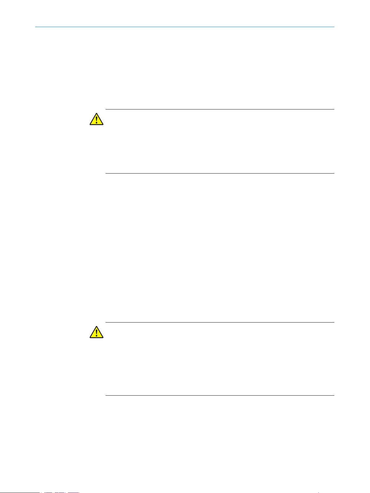
The following symbols and conventions are used in this document:
Safety notes and other notes
DANGER
Indic
ates a situation presenting imminent danger, which will lead to death or serious
injuries if not prevented.
WARNING
ates a situation presenting possible danger, which may lead to death or serious
Indic
injuries if not prevented.
CAUTION
ates a situation presenting possible danger, which may lead to moderate or minor
Indic
injuries if not prevented.
NOTICE
Indic
ates a situation presenting possible danger, which may lead to property damage if
not prevented.
NOTE
Indicates useful tips and recommendations.
Instructions to action
T
he arrow denotes instructions to action.
b
8014253/ZOH3/2017-08-04 | SICK O P ER A TI N G I NS T RU C TI O NS | deTec4 Core
Subject to change without notice
7
Page 8

1 A
BOUT THIS DOCUMENT
1. The sequence of instructions for action is numbered.
2.
Follow the order in which the numbered instructions are given.
✓
The check mark denotes the result of an instruction.
LED symbols
These symbols indicate the status of an LED:
The LED is off.
o
The LED is flashing.
Ö
The LED is illuminated continuously.
O
Sender and receiver
T
hese symbols indicate the sender and receiver of the device:
The symbol indicates the sender.
s
The symbol indicates the receiver.
r
8
O PE R AT I NG IN S TR U CT I ON S | deTec4 Core 8014253/ZOH3/2017-08-04 | SICK
Subject to change without notice
Page 9
2 Safety information
This chapter contains information on general safety for the safety light curtain.
e safety information about specific usage situations of the safety light curtain is
Mor
available in the respective chapters.
2.1 General safety notes
DANGER
H
azard due to lack of effectiveness of the protective device
In the case of non-compliance, it is possible that the dangerous state of the machine
may not be stopped or not stopped in a timely manner.
Please read this document carefully and make sure that you understand the con‐
b
tent fully before working with the device.
Follow all safety notes in this document.
b
2.2 Correct use
SAFETY INFORMATION 2
Overview
he deTec4 Core safety light curtain is an electro-sensitive protective device (ESPE) and
T
is suitable for the following applications:
Hazardous point protection
•
Access protection
•
Hazard area protection
•
The deTec4 Core safety light curtain must only be used within the limits of the prescri‐
bed and s
Any instance of improper use, incorrect modification, or manipulation of the
deTec4 Core safety light curtain shall void any warranty provided by SICK AG; further‐
more, SICK AG shall not accept any responsibility or liability for any resulting damage
and consequential damage.
Important information
DANGER
azard due to lack of effectiveness of the protective device
H
Persons and parts of the body to be protected may not be recognized in case of non-
observance.
The safety light curtain works as an indirect protective measure and cannot provide pro‐
tection from parts thrown out nor from emitted radiation. Transparent objects are not
detected.
pecified technical data and operating conditions at all times.
Only use the safety light curtain as an indirect protective measure.
b
Foreseeable misuse
g others, the deTec4 Core safety light curtain is not suitable for the following
Amon
applications:
Outdoors
•
Underwater
•
In explosion-hazardous areas
•
8014253/ZOH3/2017-08-04 | SICK O P ER A TI N G I NS T RU C TI O NS | deTec4 Core
Subject to change without notice
9
Page 10

2 S
AFETY INFORMATION
t altitudes over 3,000 m above sea level NHN
A
•
In environments with enhanced ionizing radiation
•
2.3 Requirements for the qualification of personnel
The safety light curtain must be configured, installed, connected, commissioned and
viced only by qualified safety personnel.
ser
Project planning
For project planning, a person is considered competent when he/she has expertise and
experience in the selection and use of protective devices on machines and is familiar
with the relevant technical rules and national work safety regulations.
Mechanical mounting
For mechanical mounting, a person is considered competent when he/she has the
expertise and experience in the relevant field and is sufficiently familiar with the appli‐
cation of the protective device on the machine that he/she can assess its operational
safety status.
Electrical installation
For electrical installation, a person is considered competent when he/she has the
expertise and experience in the relevant field and is sufficiently familiar with the appli‐
cation of the protective device on the machine that he/she can assess its operational
safety status.
Commissioning
or commissioning, a person is considered competent when he/she has the expertise
F
and experience in the relevant field and is sufficiently familiar with the application of
the protective device on the machine that he/she can assess its operational safety sta‐
tus.
Operation and maintenance
For operation and maintenance, a person is considered competent when he/she has
the expertise and experience in the relevant field and is sufficiently familiar with the
application of the protective device on the machine and has been instructed by the
machine operator in its operation.
An operator must clean the safety light curtain and carry out specific checks as
instructed. Additional information for the operator of the machine: see "Operation",
page 50, and see "Regular cleaning", page 51.
10
O PE R AT I NG IN S TR U CT I ON S | deTec4 Core 8014253/ZOH3/2017-08-04 | SICK
Subject to change without notice
Page 11
3 Product description
This chapter provides information on the operation of the safety light curtain and shows
xamples of its range of use.
e
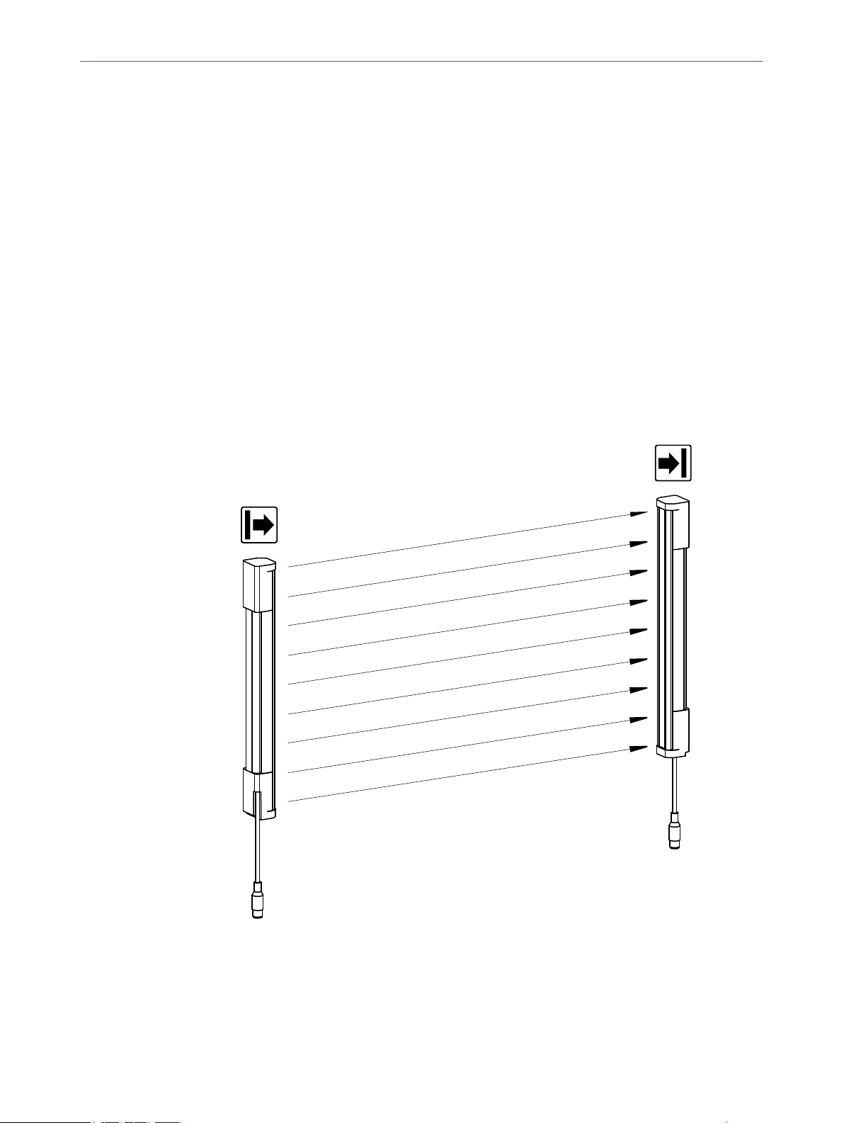
3.1 Structure and function
Overview
T
he deTec4 Core safety light curtain is an electro-sensitive protective device (ESPE) con‐
sisting of a sender and receiver.
A series of parallel infrared light beams form a protective field between sender and
receiver that protects the hazardous area (hazardous point, access, and hazardous
area protection). When one or more beams are completely interrupted, the safety light
curtain reports the interruption in the light path to the secure output signal switching
devices (OSSDs) by a signal change. The machine or its control must safely analyze the
signals (for example using a safe control or safety relays) and stop the dangerous state.
Sender and receiver automatically synchronize themselves optically. An electrical con‐
nection between both components is not required.
PRODUCT DESCRIPTION 3
Figure 1: Sender and receiver
8014253/ZOH3/2017-08-04 | SICK O P ER A TI N G I NS T RU C TI O NS | deTec4 Core
Subject to change without notice
11
Page 12

3 P
RODUCT DESCRIPTION
Protective field height
T
he protective field height indicates the range within which the test rod belonging to the
safety light curtain is reliably detected. The size of the safety light curtain determines
the protective field height. The design and construction of the safety light curtain
extends the protective function of a device to the end of the housing without any blind
spots.
Protective field width
The protective field width is the dimension of the light path between sender and
receiver. The maximum protective field width is limited by the scanning range.
Resolution
The resolution describes the size of the smallest object detected by the safety light cur‐
tain in the protective field. The resolution corresponds to the diameter of the test rod
belonging to the safety light curtain, which is reliably detected when in the protective
field.
With the appropriate resolution, the safety light curtain provides finger and hand protec‐
tion.
Scanning range
The scanning range is the maximum protective field width. It is subject to the resolution
variant (14 mm or 30 mm).
The scanning range is reduced by using deflector mirrors and/or a weld spark guard.
Further topics
"D
ata sheet", page 57
•
"Deflector mirrors", page 68
•
"Weld spark guard", page 67
•
3.2 Product characteristics
3.2.1 Absence of blind zones
The design and construction of the safety light curtain extends the protective function
of a de
vice to the end of the housing without any blind spots. The absence of blind
zones reduces the space requirement when integrated in the machine.
3.2.2 Automatic calibration of the protective field width
When switched on, the safety light curtain automatically calibrates to the protective
field width.
3.2.3 Status indicators
The sender and receiver LEDs indicate the operating status of the safety light curtain.
12
O PE R AT I NG IN S TR U CT I ON S | deTec4 Core 8014253/ZOH3/2017-08-04 | SICK
Subject to change without notice
Page 13
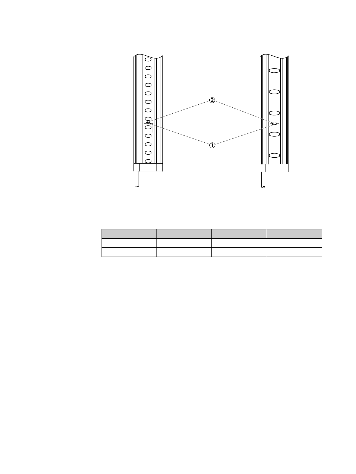
Sender indicators
Resolution 30 mmResolution 14 mm
ERR
PWR
ERR
PWR
PRODUCT DESCRIPTION 3
Figure 2: Sender indicators
T
wo light emitting diodes on the sender indicate the operational status:
Position LED color Indication Labeling
1
2
Complete overview of the LED statuses and their meanings: see "Dia
Yellow Status indicator PWR
Red Fault indicator ERR
gnostic LEDs",
page 53.
8014253/ZOH3/2017-08-04 | SICK O P ER A TI N G I NS T RU C TI O NS | deTec4 Core
Subject to change without notice
13
Page 14
Resolution 30 mmResolution 14 mm
ERR
OSSD
ERR
OSSD
1 2 3 4
1 2 3 4
2
1
3
3 P
RODUCT DESCRIPTION
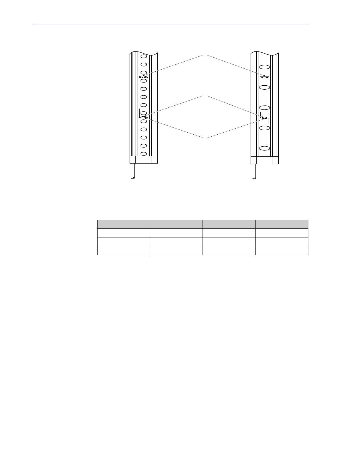
Receiver indicators
Figure 3: Receiver indicators
S
ix light emitting diodes on the receiver indicate the operational status:
Position LED color Indication Labeling
1
2
3
Red/green OSSD status OSSD
Red Fault indicator ERR
Blue Alignment quality 1, 2, 3, 4
The blue alignment quality LEDs in combination with the red flashing ERR LED also
te fault indications.
deno
Complete overview of the LED statuses and their meanings: see "Diagnostic LEDs",
page 53.
14
O PE R AT I NG IN S TR U CT I ON S | deTec4 Core 8014253/ZOH3/2017-08-04 | SICK
Subject to change without notice
Page 15
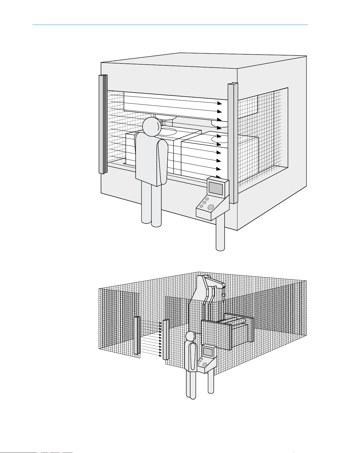
3.3 Example applications
PRODUCT DESCRIPTION 3
Figure 4: Hazardous point protection
Figure 5: Access protection
8014253/ZOH3/2017-08-04 | SICK O P ER A TI N G I NS T RU C TI O NS | deTec4 Core
Subject to change without notice
15
Page 16
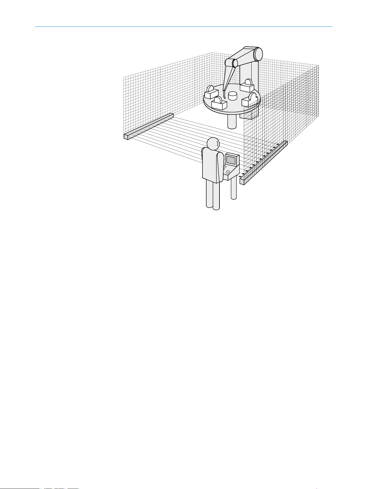
3 P
RODUCT DESCRIPTION
Figure 6: Hazardous area protection
16
O PE R AT I NG IN S TR U CT I ON S | deTec4 Core 8014253/ZOH3/2017-08-04 | SICK
Subject to change without notice
Page 17

4 Project planning
This chapter includes important information about the proper integration of the safety
ght curtain in machines for planners, developers and designers.
li
4.1 Manufacturer of the machine
DANGER
H
azard due to lack of effectiveness of the protective device
Persons and parts of the body to be protected may not be recognized in case of nonobservance.
Conduct a risk assessment and check whether additional protective measures are
b
required.
Comply with the applicable national regulations derived from the application (e.g.,
b
work safety regulations, safety rules, or other relevant safety guidelines).
Do not combine the components of the safety light curtain with components from
b
other safety light curtains.
Apart from for the procedures described in this document, the components of the
b
safety light curtain must not be opened.
The components of the safety light curtain must not be tampered with or changed.
b
Do not carry out any repairs on the device components. Improper repair of the pro‐
b
tective device can lead to a loss of the protective function.
PROJECT PLANNING 4
4.2 Operator of the machine
DANGER
H
azard due to lack of effectiveness of the protective device
Persons and parts of the body to be protected may not be recognized in case of nonobservance.
Changes to the electrical integration of the safety light curtain in the machine con‐
b
trol and changes to the mechanical installation of the safety light curtain require
another risk assessment. The results of this risk assessment may require the
operator of the machine to meet the obligations of a manufacturer.
Apart from the procedures described in this document, the components of the
b
safety light curtain must not be opened.
The components of the safety light curtain must not be tampered with or changed.
b
Do not carry out any repairs on the device components. Improper repair of the pro‐
b
tective device can lead to a loss of the protective function.
4.3 Design
Overview
T
his chapter contains important information about the design.
8014253/ZOH3/2017-08-04 | SICK O P ER A TI N G I NS T RU C TI O NS | deTec4 Core
Subject to change without notice
17
Page 18

4 PROJECT PLANNING
Important information
DANGER
azard due to lack of effectiveness of the protective device
H
Persons and parts of the body to be protected may not be recognized in case of non-
observance.
Make sure that the following construction requirements are met so that the safety
b
light curtain can fulfill its protective function.
Sender and receiver must be arranged such that persons or parts of the body
°
are reliably detected when they enter the hazardous area.
Reaching under, over, and around as well as moving the safety light curtain
°
must be prevented.
Check whether additional safety measures (e.g. restart interlocking) are nec‐
°
essary when it is possible for people to be located between the protection
system and the danger point without being detected.
Further topics
"Mount
•
4.3.1 Scanning range and protective field width
Important information
DANGER
H
azard due to lack of effectiveness of the protective device
Persons and parts of the body to be protected may not be recognized in case of nonobservance.
The safety light curtain can only be mounted on machines on which the protective
b
field width does not change when the safety light curtain is switched on.
Scanning range
he scanning range limits the maximum protective field width. The protective field width
T
cannot change during operation.
The scanning range is reduced by using deflector mirrors and/or a weld spark guard.
Protective field width
T
he protective field width is the dimension of the light path between sender and
receiver.
The protective field width is automatically calibrated when the safety light curtain is
switched on during initialization and must not be changed during operation.
ing", page 31
Further topics
"T
echnical data", page 57
•
"Deflector mirrors", page 68
•
"Weld spark guard", page 67
•
4.3.2 Minimum distance from the hazardous point
Overview
18
A minimum dis
ardous point. This distance is required to prevent a person or part of their body from
reaching the hazardous point before the end of the machine’s dangerous state.
O PE R AT I NG IN S TR U CT I ON S | deTec4 Core 8014253/ZOH3/2017-08-04 | SICK
tance must be maintained between the safety light curtain and the haz‐
Subject to change without notice
Page 19
PROJECT PLANNING 4
Calculating the minimum distance according to ISO 13855
T
he calculation of the minimum distance is based on international or national stand‐
ards and statutory requirements applicable at the place of installation of the machine.
If the minimum distance is calculated according to ISO 13855, it depends on the fol‐
lowing points:
Machine stopping time (time interval between triggering the sensor function and
•
the end of the machine’s dangerous state)
Response time of the Protective Equipment.
•
Reach or approach speed of the person
•
Resolution (detection capability) of the safety light curtain
•
Type of approach: orthogonal (at right angles) or parallel
•
Parameters specified based on the application
•
For the USA (scope of OSHA and ANSI), different regulations may apply, e.g.:
a) Laws: Code of Federal Regulations, Title 29 (CFR 29), Part 1910.217
b) Standards: ANSI B11.19
Complementary information
A
dditional information is available in the ISO 13855 standard and in the Guidelines
Safe Machinery.
SICK offers a stopping/run-down time measurement service in many countries.
Further topics
"R
esponse time", page 59
•
4.3.2.1 Calculating minimum distance from the hazardous point
Important information
DANGER
Minimum dis
The dangerous state of the machine may not be stopped or not be stopped in a timely
manner due to a minimum distance that is too small.
Calculate the minimum distances for the machine in which the safety light curtain
b
is integrated.
When mounting the safety light curtain, observe the minimum distance.
b
Approach
The example shows the calculation of the minimum distance for an orthogonal (rightangled) approach to the protective field. A different calculation may be required
depending on the application and the ambient conditions (e.g., for a protective field
parallel to or at any angle to the direction of approach or an indirect approach).
tance from the hazardous point is too small
1. First, calculate S using the following formula:
S = 2,000 mm/s × T + 8 ×(d – 14 mm)
Where:
S = minimum dis
°
T = machine stopping time + response time of the protective device after
°
interruption in the light path in seconds (s)
d = resolution of the safety light curtain in millimeters (mm)
°
The reach or approach speed is already included in the formula.
2. If the result S is ≤ 500 mm, then use the determined value as the minimum dis‐
ance.
t
8014253/ZOH3/2017-08-04 | SICK O P ER A TI N G I NS T RU C TI O NS | deTec4 Core
Subject to change without notice
tance in millimeters (mm)
19
Page 20

3
4
1
2
4 P
ROJECT PLANNING
3. If the result S is > 500 mm, then recalculate S as follows:
S = 1,600 mm/s × T + 8 ×(d – 14 mm)
4. If the new value S is > 500 mm, then use the newly determined value as the mini‐
mum dis
tance.
5. If the new value S is ≤ 500 mm, then use 500 mm.
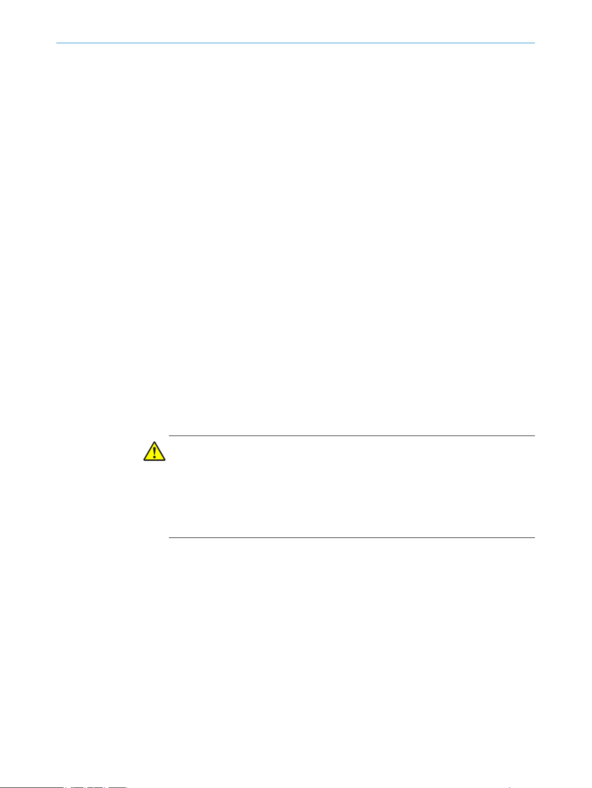
Figure 7: Minimum distance to hazardous point for orthogonal (right-angled) approach to protec‐
t
ive field
Minimum distance S
1
Protective field height
2
Hazardous point
3
Depending on the application and distance, persons must be prevented from standing
4
behind the protective device.
Example calculation
Mac
hine stopping time = 290 ms
Response time after interruption of the light path = 30 ms
Resolution of the safety light curtain = 14 mm
T = 290 ms + 30 ms = 320 ms = 0.32 s
S = 2,000 mm/s × 0.32 s + 8 × (14 mm – 14 mm) = 640 mm
S > 500 mm, therefore:
S = 1,600 mm/s × 0.32 s + 8 × (14 mm – 14 mm) = 512 mm
4.3.2.2 Taking reach over into account
If access to the hazardous area by reaching over a protective field cannot be prevented,
t
he height of the protective field and minimum distance of the ESPE must be deter‐
mined. This is done by comparing the calculated values based on the possible detec‐
tion of limbs or body parts with the values resulting from reaching over the protective
field. The greater value resulting from this comparison must be used.
20
O PE R AT I NG IN S TR U CT I ON S | deTec4 Core 8014253/ZOH3/2017-08-04 | SICK
Subject to change without notice
Page 21
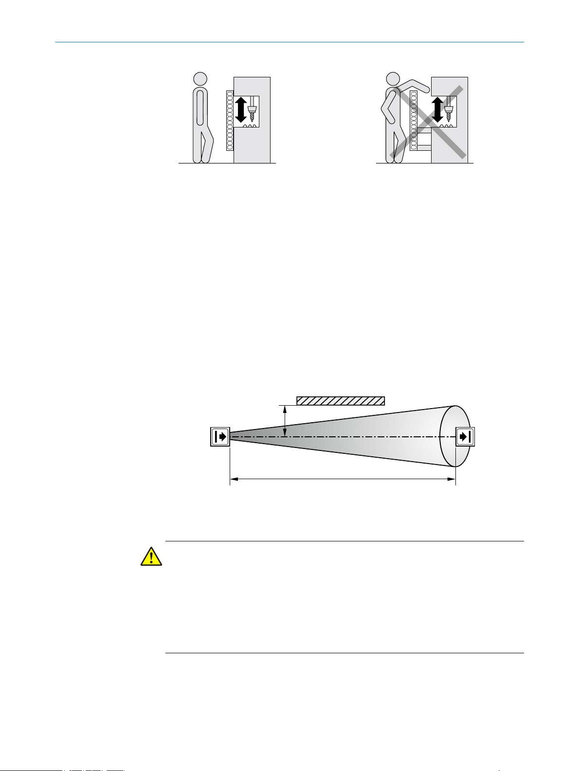
Figure 8: Representation of the accessibility of electro-sensitive protective device by reaching
D
a
o
ver. Left: Protective field that cannot be reached over. Right: Protective field that can be reached
over.
4.3.3 Minimum distance to reflective surfaces
Overview
T
he light beams from the sender may be deflected by reflective surfaces and dispersive
media. This may prevent an object from being detected.
Therefore, all reflective surfaces and objects (e.g. material bins, machine table, etc.)
must maintain a minimum distance (a) from the protective field. This minimum dis‐
tance (a) must be maintained on all sides of the protective field. This applies in horizon‐
tal, vertical and diagonal directions as well as at the end of the safety light curtain. The
same area must be free of dispersive media (e.g., dust, fog, or smoke).
PROJECT PLANNING 4
The minimum distance (a) depends on the distance (D) between sender and receiver
(protective field width).
Figure 9: Minimum distance from reflective surfaces
Important information
DANGER
azard due to lack of effectiveness of the protective device
H
Reflective surfaces and dispersive media can prevent persons or parts of the body to
be protected from being properly reflected and, therefore, remain undetected.
Make sure that all reflective surfaces and objects maintain a minimum distance
b
from the protective field.
Make sure that no dispersive media (e.g., dust, fog, or smoke) are within the calcu‐
b
lated minimum distance from the protective field.
Determining minimum distance to reflective surfaces
D
etermine the distance between sender and receiver D in meters (m).
b
Read the minimum distance a in millimeters (mm) in the graph or calculate it
b
based on the respective formula table 1:
8014253/ZOH3/2017-08-04 | SICK O P ER A TI N G I NS T RU C TI O NS | deTec4 Core
Subject to change without notice
21
Page 22
500
400
300
200
100
a/mm
1 2 3 4 5 6 7 8 9 10 11 12 D/m
1
2
4 PROJECT PLANNING
Figure 10: Graph of minimum distance from reflective surfaces
T
able 1: Formula for calculating the minimum distance from reflective surfaces
Distance D between sender and
r
eceiver in m
D ≤ 3 m a = 131 mm
D > 3 m a = tan (2.5°) × 1,000 mm/m × D = 43.66 × 1 mm/m ×
Calculation of the minimum distance (a) from reflective
surfaces in mm
D
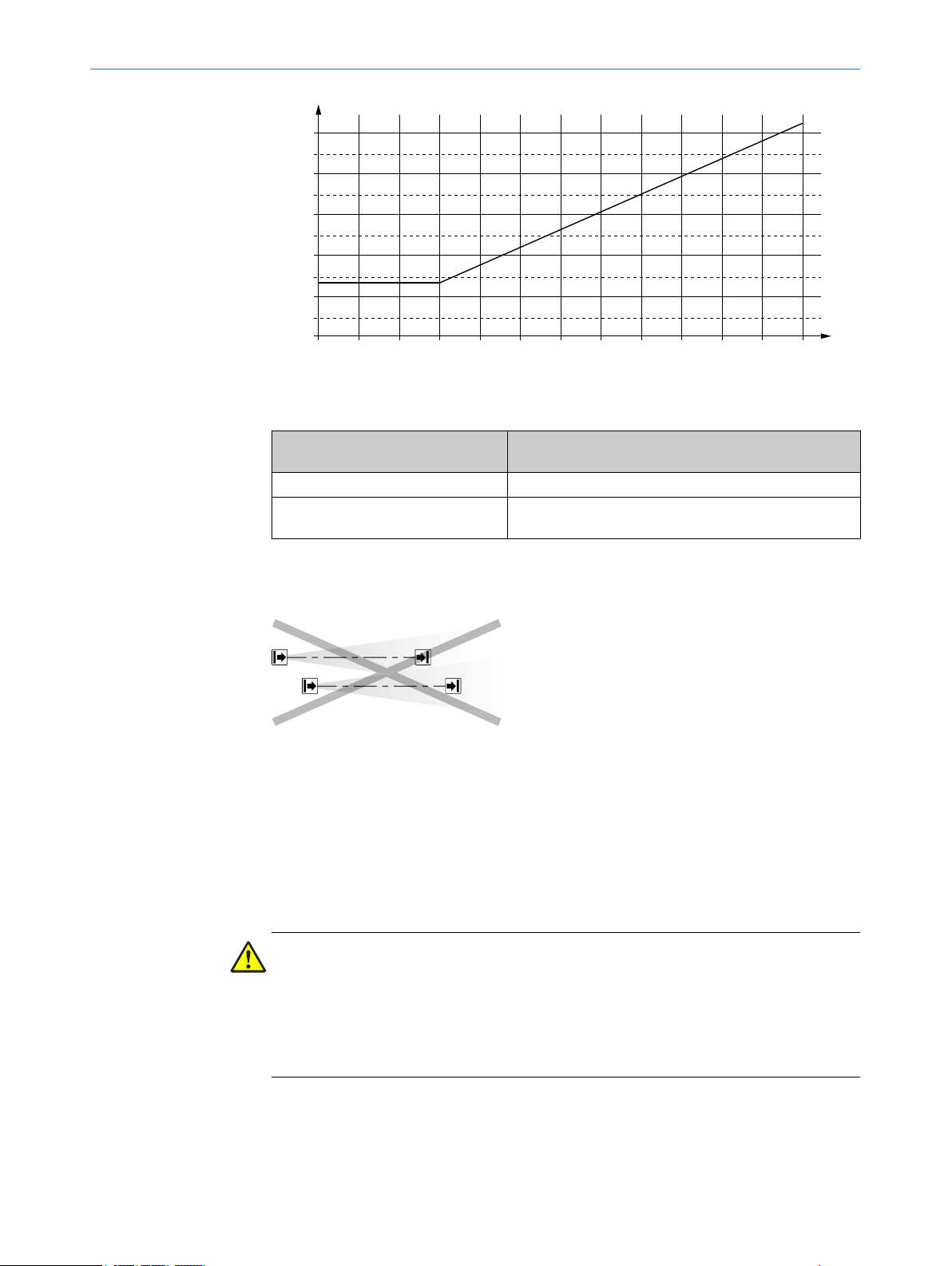
4.3.4 Protection against interference from systems in close proximity to each other
Overview
1
Figure 11: Preventing mutual interference from system
and system
The infrared light beams of the sender of system 1 can interfere with the receiver of
system 2. This can disrupt the protective function of system 2. This would mean that
the operator is at risk.
Avoid such installation situations or take appropriate action, e.g., install optically opa‐
que partitions or reverse the direction of transmission of a system.
Important information
DANGER
azard due to lack of effectiveness of the protective device
H
Systems of safety light curtains that operate in close proximity to each other can inter‐
fere with each other.
Use appropriate measures to prevent systems in close proximity from interfering
b
with each other.
2
22
O PE R AT I NG IN S TR U CT I ON S | deTec4 Core 8014253/ZOH3/2017-08-04 | SICK
Subject to change without notice
Page 23
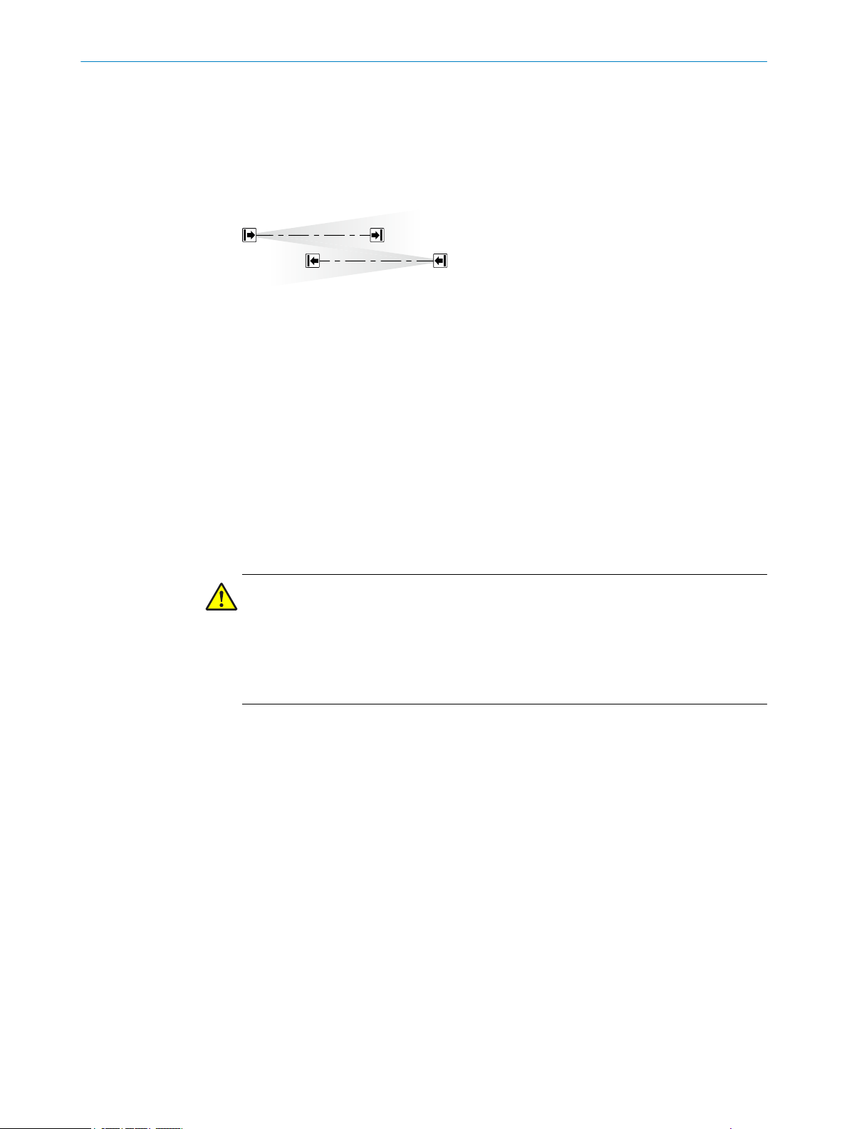
4.3.4.1 Using reversed direction of transmission
1
2
Using reversed direction of transmission
T
he direction of transmission of the system 2 can be changed during installation by
switching the positions of the sender and receiver. With reversed direction of transmis‐
sion, the receiver 2 is not affected by the infrared light from the sender 1.
Figure 12: Trouble-free operation due to reversed direction of transmission of system
tem
2
4.4 Integration in electrical control
Overview
his chapter contains important information about integration in the electrical control.
T
Information about the individual steps for electrical installation of the device: see "Elec‐
trical installation", page 41.
PROJECT PLANNING 4
1
and sys‐
Requirements for use
The output signals of the protective device must be analyzed by downstream controllers
in such a way that the dangerous state of the machine is ended safely. Depending on
the safety concept, the signal is analyzed by, e.g., safety relays or a safety controller.
DANGER
azard due to lack of effectiveness of the protective device
H
In the case of non-compliance, it is possible that the dangerous state of the machine
may not be stopped or not stopped in a timely manner.
Make sure that the following control and electrical requirements are met so that
b
the safety light curtain can fulfill its protective function.
t be possible to electrically influence the control of the machine.
It mus
•
The electrical control of the machine must meet the requirements of IEC 60204-1.
•
A restart interlock must be implemented depending on applicable national regula‐
•
tions or required reliability of the safety function. Because the safety light curtain
does not have this function, it must be implemented in the external control if
required.
When using a safety controller, different signal levels of both OSSDs must be
•
detected depending on applicable national regulations or required reliability of the
safety function. The maximum discrepancy time tolerated by the control must be
selected according to the application.
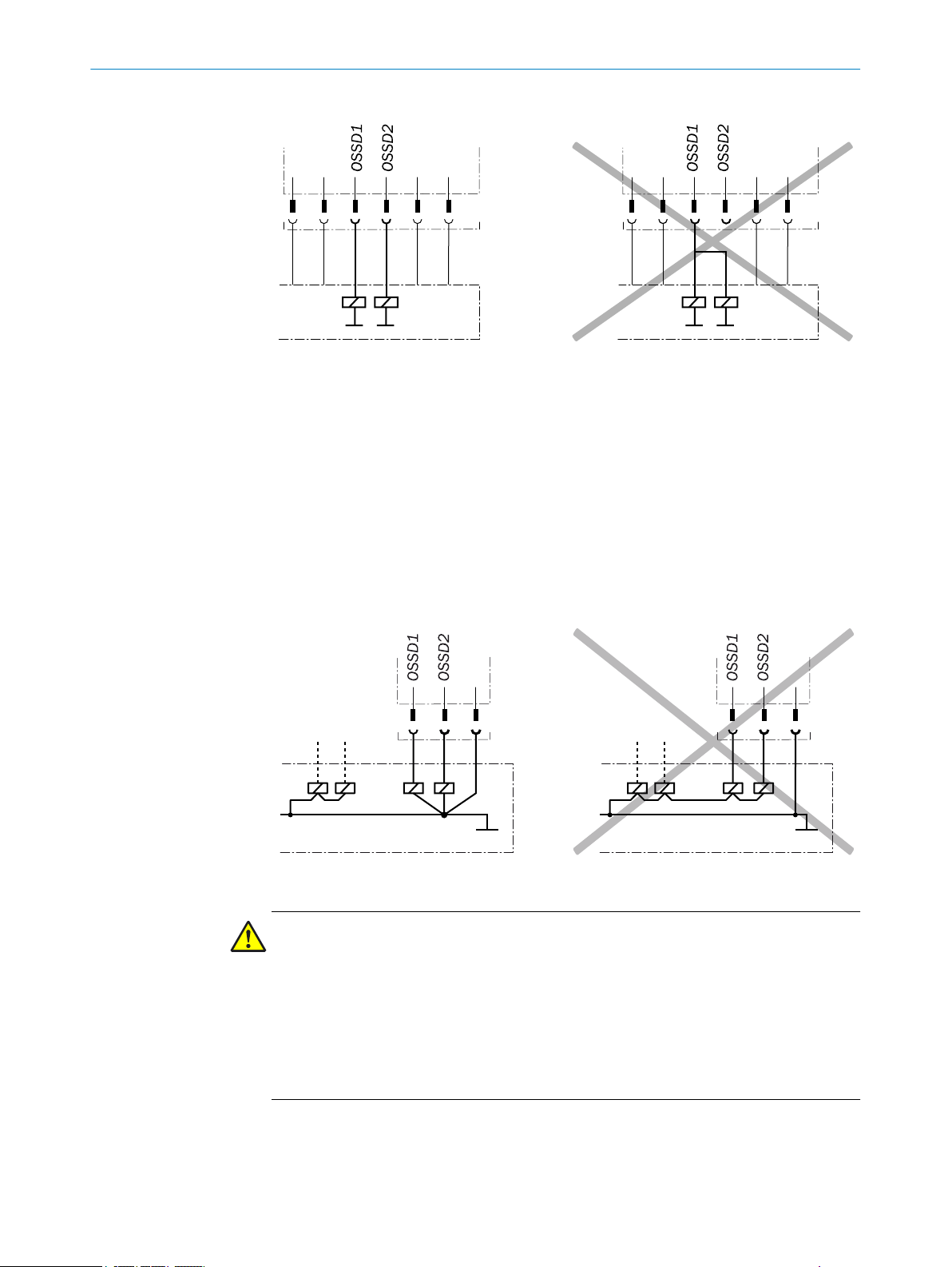
The OSSD1 and OSSD2 output signals must not be connected to each other.
•
In the machine controller, the signals of both OSSDs must be processed sepa‐
•
rately.
8014253/ZOH3/2017-08-04 | SICK O P ER A TI N G I NS T RU C TI O NS | deTec4 Core
Subject to change without notice
23
Page 24
4 P
ROJECT PLANNING
Figure 13: Dual-channel and isolated connection of OSSD1 and OSSD2
he machine must switch to the safe state at any time if at least one of the two
T
•
OSSDs switches to the OFF state.
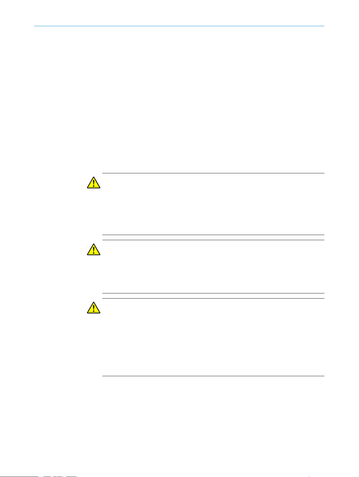
Prevent the formation of a potential difference between the load and the protec‐
•
tive device. If you connect loads to the OSSDs (safety outputs) that then also
switch if controlled with negative voltage (e.g., electro-mechanical contactor with‐
out reverse polarity protection diode), you must connect the 0 V connections of
these loads and those of the corresponding protective device individually and
directly to the same 0 V terminal strip. In the event of a fault, this is the only way to
ensure that there can be no potential difference between the 0 V connections of
the loads and those of the corresponding protective device.
24
Figure 14: No potential difference between load and protective device
DANGER
azard due to lack of effectiveness of the protective device
H
In the case of non-compliance, it is possible that the dangerous state of the machine
may not be stopped or not stopped in a timely manner.
Downstream contactors must be positively guided and monitored depending on appli‐
cable national regulations or required reliability of the safety function.
Make sure that downstream contactors are monitored (external device monitoring,
b
EDM).
ause the safety light curtain does not have integrated external device monitor‐
Bec
b
ing, this must be implemented in the external control, if required.
O PE R AT I NG IN S TR U CT I ON S | deTec4 Core 8014253/ZOH3/2017-08-04 | SICK
Subject to change without notice
Page 25

PROJECT PLANNING 4
Requirements for the electrical control of the machine
T
he two outputs are short-circuit protected against 24 V DC and 0 V. When the protec‐
tive field is clear, the OSSDs are in the ON state and the signal level is HIGH (non-iso‐
lated). In the event of an interruption in the light path or device fault, the OSSDs are in
the OFF state and the signal level is LOW (above 1.5 kΩ to 0 V).
The safety light curtain complies with the rules for electromagnetic compatibility (EMC)
for the industrial sector (Radio Safety Class A). Radio interference cannot be ruled out
when used in residential areas.
DANGER
Hazard due to lack of effectiveness of the protective device
In the case of non-compliance, it is possible that the dangerous state of the machine
may not be stopped or not stopped in a timely manner.
Make sure that the following control and electrical requirements are met so that
b
the safety light curtain can fulfill its protective function.
The external voltage supply of the safety light curtain must be capable of jumper‐
•
ing a brief power failure of 20 ms as specified in IEC 60204-1.
The power supply unit must ensure safe isolation according to IEC 61140
•
(SELV/PELV). Suitable power supply units are available as accessories from SICK,
see "Accessories", page 64.
4.4.1 Restart interlock
Overview
D
epending on the regulations which apply at the place of installation, a restart interlock
may be required.
The restart interlock prevents the machine from automatically starting up, for example
after a protective device has responded while the machine is operating or after chang‐
ing the machine’s operating mode.
The safety light curtain does not have an internal restart interlock. If required, a restart
int
in connection with the SICK switching amplifier UE48-2OS/UE48-3OS.
Principle of operation
The restart interlock prevents the machine from automatically starting up, for example
after a protective device has responded while the machine is operating or after chang‐
ing the machine’s operating mode.
Before the machine can be restarted, the operator must reset the restart interlock.
erlock must therefore be implemented externally via the circuitry or the control, e.g.,
Figure 15: Schematic representation of operation with restart interlock
8014253/ZOH3/2017-08-04 | SICK O P ER A TI N G I NS T RU C TI O NS | deTec4 Core
Subject to change without notice
25
Page 26

S34 S21S35 S22
S33 S12S11 S31
14A2 24 32
13A1 23 31
UE48-2OS2D2
K1 K2
S1
K1
K2
OSSD1
OSSD2
n.c.
GND
+24V
1
2
3
4
5
+24V
n.c.
GND
n.c.
n.c.
1
2
3
4
5
24 VDC
0 VDC
ROJECT PLANNING
4 P
The dangerous state of the machine 1 is br
rupted 2 and is not re-enabled 3 until the operator presses the reset pushbutton
located outside the hazardous area 4. The machine can then be restarted.
Depending on the applicable national regulations, there must be a restart interlock if a
person can stand behind the protective field. Observe IEC 60204-1.
4.4.2 External device monitoring (EDM)
Overview
T
he external switching elements (external device monitoring, EDM) must be inspected
in line with the regulations which apply at the place of installation or the required relia‐
bility of the safety function.
The external device monitoring (EDM) monitors the status of downstream contactors.
Important information
NOTE
Bec
ause the safety light curtain does not have integrated external device monitoring,
this must be implemented in the external control, if required.
Prerequisites
ositively guided contactors are used for shutting down the machine.
P
•
If the auxiliary contacts of the positively guided contactors are connected to the
external device monitoring, the external device monitoring checks whether the
contactors drop off when the OSSDs are switched off.
ought to an end if the light path is inter‐
4.4.3 Connection diagrams
Connection diagram for UE48-2OS with restart interlock and external device monitor‐
in
g
26
Figure 16: Connection diagram for UE48-2OS with restart interlock and external device monitor‐
in
g
O PE R AT I NG IN S TR U CT I ON S | deTec4 Core 8014253/ZOH3/2017-08-04 | SICK
Subject to change without notice
Page 27

4.5 Testing plan
PROJECT PLANNING 4
The safety light curtain can be connected to the UE48-2OS switching amplifiers. It is
oper
ated with restart interlock and external device monitoring.
Functionality
When the protective field is clear, the OSSD1 and OSSD2 outputs carry voltage. The
system can be switched on when K1 and K2 are in the de-energized position. Pressing
the S1 button switches on the UE48 switching amplifier. Contacts 13-14 and 23-24 of
the UE48 activate the K1 and K2 contactors.
When the protective field is interrupted, the OSSD1 and OSSD2 outputs carry no volt‐
age. The UE48 switches off and K1, K2 are deactivated.
Fault analysis
Failure of K1 and K2 does not cause the loss of the shut-down function. Cross-circuits
and short-circuits of the OSSD1 and OSSD2 outputs are recognized and lead to the
locking state. It is recognized if the K1 or K2 contactors do not de-energize.
The manufacturer of the machine and the operating entity must define all required
c
hecks. The definition must be based on the application conditions and the risk assess‐
ment and must be documented in a traceable manner.
When defining the check, please note the following:
b
Define the type and execution of the check.
°
Define the frequency of the check.
°
Notify the machine operators of the check and instruct them accordingly.
°
The following checks are often defined in connection with a protective device:
Check during commissioning and modifications
•
Regular thorough check
•
Check during commissioning and modifications
The check must detect if it is possible to enter the hazardous area without being
detected.
The following points are often helpful for the definition of the check:
Does the check have to be completed by quality safety personnel?
•
Can the check be completed by personnel specially qualified and authorized per‐
•
sonnel?
Does the check have to be documented in a traceable manner?
•
Can the check be carried out according to a check list? (see "Checklist for initial
•
commissioning and commissioning", page 75)
Do the machine operators know the function of the protective device?
•
Have the machine operators been trained to work on the machine?
•
Have the machine operators been notified about modifications on the machine?
•
Does the hazardous area to be secured have to be checked with a test rod? (see
•
"Test rod check", page 28)
Define all guidelines for the check.
b
Regular thorough check
T
he check must detect if it is possible to enter the hazardous area without being
detected. Such possibilities may exist due to modifications, manipulations or external
influences.
The following points are often helpful for the definition of the check:
Which check must be carried out and how is it carried out?
•
8014253/ZOH3/2017-08-04 | SICK O P ER A TI N G I NS T RU C TI O NS | deTec4 Core
Subject to change without notice
27
Page 28
4 PROJECT PLANNING
4.5.1 Test rod check
est rod check, page 28
T
°
Visual check of the machine and the protective device, page 29
°
How often does the check have to be carried out?
•
Do the machine operators have to be notified of the check and do they need to be
•
instructed accordingly?
Define all guidelines for the check.
b
Overview
T
he rod test check is used to check whether the hazardous point is only accessible via
the protective field of the safety light curtain and whether the protective device is able
to identify each time the hazardous point is approached.
The test is carried out with an opaque test rod whose diameter corresponds to the reso‐
lution of the safety light curtain.
Important information
DANGER
Use of incor
Persons or parts of the body to be protected may not be detected in operation.
rect test rods
Only use the included test rod with the diameter specified on the type label of the
b
safety light curtain.
Do not use any test rods with a similar or the same diameter of other safety light
b
curtains.
DANGER
H
azard due to unexpected starting of the machine
Make sure that the dangerous state of the machine is and remains switched off
b
during the check.
Make sure that the outputs of the safety light curtain have no effect on the
b
machine during the check of the components.
DANGER
H
azard due to lack of effectiveness of the protective device
Persons and parts of the body to be protected may not be recognized in case of nonobservance.
Do not operate the machine if the OSSD LED lights up green during the test!
If the OSSD LED lights up green during the test even if only briefly, work must stop
b
at the machine.
In this case, the mounting and electrical installation of the safety light curtain
b
must be checked by qualified safety personnel.
28
Prerequisites
The OSSD LED lights up green.
•
O PE R AT I NG IN S TR U CT I ON S | deTec4 Core 8014253/ZOH3/2017-08-04 | SICK
Subject to change without notice
Page 29

PROJECT PLANNING 4
Approach
1.
Move the test rod slowly through the protective field to be protected (e.g., machine
opening as indicated by the arrow, see figure 17, page 29).
2. Watch the OSSD LED on the receiver during the check. The OSSD LED on the
receiver should continuously light up red. The OSSD LED must not illuminate
green.
Figure 17: Test rod check: Step 1
3.
Then, guide the test rod along the edges of the area to be protected as indicated
by the arrow, see figure 18.
4. Watch the OSSD LED on the receiver during the check. The OSSD LED on the
receiver should continuously light up red. The OSSD LED must not illuminate
green.
Figure 18: Test rod check: Step 2
If one or more deflector mirrors are used, then the test rod should also be guided
5.
slowly through the area to be protected directly in front of the deflector mirrors.
6. Watch the OSSD LED on the receiver during the check. The OSSD LED on the
receiver should continuously light up red. The OSSD LED must not illuminate
green.
4.5.2 Visual check of the machine and the protective device
The following points are often helpful for the definition of the check:
8014253/ZOH3/2017-08-04 | SICK O P ER A TI N G I NS T RU C TI O NS | deTec4 Core
Subject to change without notice
29
Page 30

4 P
ROJECT PLANNING
as the machine been retrofitted?
H
•
Have machine parts been removed?
•
Have modifications been made to the surroundings of the machine?
•
Have the protective device or its parts been dismantled?
•
Is it possible to enter the hazardous area without being detected?
•
Is the protective device damaged?
•
Is the protective device severely contaminated?
•
Is the front screen contaminated, scratched or destroyed?
•
Are there any damaged cables or open cable ends?
•
If one of the points applies, the machine should be shut down immediately. In this case,
the machine and the protective device must be checked by appropriately qualified
safety personnel.
30
O PE R AT I NG IN S TR U CT I ON S | deTec4 Core 8014253/ZOH3/2017-08-04 | SICK
Subject to change without notice
Page 31

5 Mounting
5.1 Safety
MOUNTING 5
Important information
DANGER
D
angerous state of the machine
Make sure that the dangerous state of the machine is (and remains) switched off
b
during mounting, electrical installation, and commissioning.
Make sure that the outputs of the safety light curtain do not affect the machine
b
during mounting, electrical installation, and commissioning.
DANGER
azard due to lack of effectiveness of the protective device
H
If unsuitable brackets are used or if subjected to excessive vibrations, the device may
become detached or damaged.
Persons and parts of the body to be protected may not be recognized in case of non-
observance.
Only use SICK-approved brackets for mounting.
b
Take appropriate measures for vibration damping if vibration and shock specifica‐
b
tions exceed the values and test conditions specified in the data sheet.
DANGER
azard due to lack of effectiveness of the protective device
H
Persons and parts of the body to be protected may not be recognized in case of non-
observance.
Do not do repair work on device components.
b
Do not make changes to or manipulate device components.
b
Apart from the procedures described in this document, the device components
b
must not be opened.
NOTE
Mount t
Prerequisites
T
Further topics
•
•
he device in the following order.
he construction of the safety light curtain has been correctly executed.
"Design", page 17
"Technical data", page 57
5.2 Unpacking
Approach
1.
Check the components for completeness and integrity for all parts.
2. Please contact your respective SICK subsidiary should you have any complaints.
Further topics
"Scope of delivery", page 63
•
8014253/ZOH3/2017-08-04 | SICK O P ER A TI N G I NS T RU C TI O NS | deTec4 Core
Subject to change without notice
31
Page 32

5 MOUNTING
5.3 Installation
Overview
he QuickFix bracket or the FlexFix bracket is used to mount the sender and receiver. In
T
many cases, the QuickFix bracket is enough for mounting. The FlexFix bracket makes it
possible to rotate the sender and receiver around the axis of the device and to align it
accurately.
Important information
NOTE
ead this section completely before installing the safety light curtain.
R
b
Read the information on aligning the sender and receiver.
b
DANGER
H
azard due to lack of effectiveness of the protective device
Persons or parts of the body to be protected may not be recognized or not recognized in
time in case of non-observance.
Observe the calculated minimum distances for the machine in which the safety
b
light curtain is integrated.
Then, mount the safety light curtain such that it is not possible to reach below,
b
above, around, or behind the safety light curtain, and that the light curtain cannot
be repositioned.
DANGER
H
azard due to lack of effectiveness of the protective device
Persons and parts of the body to be protected may not be recognized in case of nonobservance.
The safety light curtain can only be mounted on machines on which the protective
b
field width does not change when the safety light curtain is switched on.
DANGER
H
azard due to lack of effectiveness of the protective device
Persons and parts of the body to be protected may not be recognized in case of nonobservance.
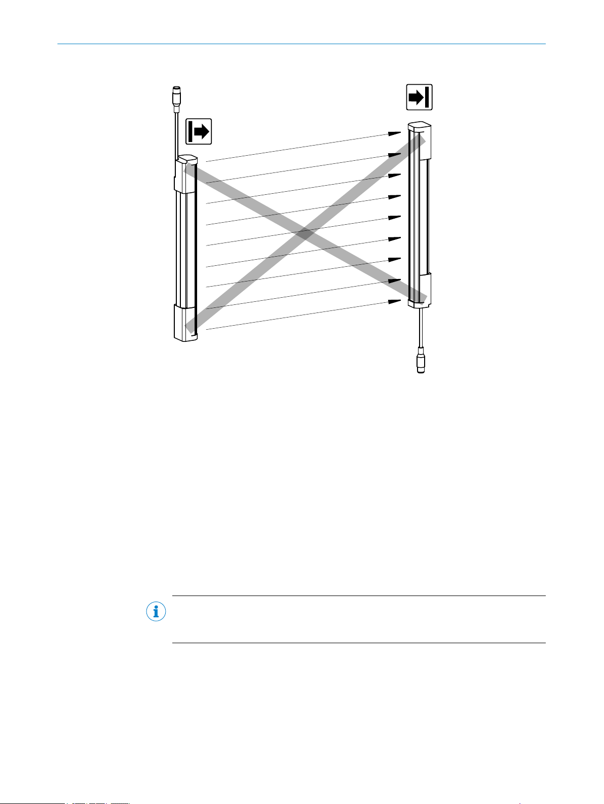
The end with the cable connection must point in the same direction for the sender
b
and receiver.
32
O PE R AT I NG IN S TR U CT I ON S | deTec4 Core 8014253/ZOH3/2017-08-04 | SICK
Subject to change without notice
Page 33
Approach
MOUNTING 5
Figure 19: Sender and receiver must not be installed at 180° rotated relative to each other
Mount t
b
Mount the sender and receiver such that a right-angled protective field is estab‐
b
lished, i.e., when mounted vertically at the same height. For minor adjustments
when aligning, the sender and receiver can be adjusted longitudinally in the brack‐
ets.
If possible, select the mounting height of the top bracket such that the offset in
b
the safety light curtain housing is resting on the bracket. This prevents the safety
light curtain from sliding down during mounting.
Tightening torque for the screws used to mount the bracket: 5 Nm … 6 Nm. Tight‐
b
ening torque for the screws used to secure the safety light curtain in the bracket:
2.5 Nm … 3 Nm. Higher torques can damage the bracket while lower torques do
not provide adequate fixation to prevent the safety light curtain from moving.
Make sure that the sender and receiver are aligned correctly. The optical lens sys‐
b
tems of the sender and the receiver must be located opposite one another.
If necessary, use a spirit level to check that the components are parallel.
b
NOTE
W
hen mounting the brackets, take into account that the brackets can not be mounted
at the same height if different system connectors are used on the sender and receiver.
Further topics
"Minimum dis
•
"Minimum distance to reflective surfaces", page 21
•
"Alignment of the sender and receiver", page 45
•
"Alignment with the QuickFix bracket", page 47
•
"Alignment with the FlexFix bracket or with the upgrade bracket", page 47
•
he sender and receiver on a level surface.
tance from the hazardous point", page 18
8014253/ZOH3/2017-08-04 | SICK O P ER A TI N G I NS T RU C TI O NS | deTec4 Core
Subject to change without notice
33
Page 34

5 MOUNTING
5.3.1 Mounting the QuickFix bracket
Overview
2 Q
uickFix brackets are used to mount the sender and receiver.
The QuickFix bracket consists of 2 parts, which are pushed into each other. The two
individual parts are connected with an M5 screw and the housing (sender or receiver) is
clamped with form-fit clamping.
The two mounting surfaces for the brackets of the sender or receiver must be parallel
and lie in the same plane.
Important information
NOTE
he following should be considered when mounting the QuickFix bracket:
T
Select the appropriate length of the M5 screw to prevent any risk of injury from an
•
overrun.
When selecting the screw length, observe the wall thickness and the depth of the
•
countersunk screw of the QuickFix bracket, see figure 32, page 64
NOTE
he QuickFix bracket has cable routing. Depending on the installation, the cable routing
T
can make mounting easier.
Mount QuickFix bracket on a machine or profile frame
T
able 2: Lateral and rear mounting with the QuickFix bracket
Mounting type Description
On the side With the M5 screw through the QuickFix bracket to the machine or profile
fr
ame. A screw nut or threaded hole is required on the machine or profile
frame.
Mount through the machine or profile frame to the QuickFix bracket using
the M5 screw. A screw nut is required for each QuickFix bracket.
On the back With the M5 screw through the QuickFix bracket to the machine or profile
frame. A screw nut or threaded hole is required on the machine or profile
frame.
34
O PE R AT I NG IN S TR U CT I ON S | deTec4 Core 8014253/ZOH3/2017-08-04 | SICK
Subject to change without notice
Page 35

1 2
Figure 20: Mounting the QuickFix bracket to a profile
Mounting on the side
1
Mounting on the back
2
MOUNTING 5
5.3.2 Mounting the FlexFix bracket
Overview
In t
he FlexFix bracket, the sender and receiver can be rotated ± 15° around their longi‐
tudinal axis.
2 FlexFix brackets are used to mount the sender and receiver.
Important information
NOTICE
T
he housing of the safety light curtain can become scratched if the screw heads pro‐
trude when the FlexFix brackets are mounted on the back.
This can be avoided by taking one of the following measures:
Use flat-head screws with washers.
b
If using cylinder head screws, use 2 screws per bracket and no washers.
b
NOTE
T
he FlexFix mounting kit (part number 2073543) contains 2 FlexFix brackets, one align‐
ment tool, and the required screws, sliding nuts, and washers.
Further topics
ackets", page 64
"Br
•
5.3.2.1 Mounting the FlexFix bracket on a machine or profile frame
Important information
NOTE
hen selecting the screw length, observe the wall thickness of the FlexFix bracket, see
W
figure 33, page 65.
8014253/ZOH3/2017-08-04 | SICK O P ER A TI N G I NS T RU C TI O NS | deTec4 Core
Subject to change without notice
35
Page 36

1 2
5 MOUN
TING
Mounting type
T
able 3: Lateral and rear mounting with the FlexFix bracket
Mounting type Description
On the side With the M5 screw through the FlexFix bracket to the machine or profile
fr
ame. A screw nut or threaded hole is required on the machine or profile
frame.
On the back With the M5 screw through the FlexFix bracket to the machine or profile
frame. A screw nut or threaded hole is required on the machine or profile
frame.
Figure 21: Mount FlexFix brackets to a profile frame
Mounting on the side
1
Mounting on the back
2
Approach
After mounting the FlexFix brackets, screw the sender and receiver into the FlexFix
1.
brackets from the front and align the sender and receiver.
NOTE
he safety light curtain can only be screwed in when both FlexFix brackets are in align‐
T
ment.
Recommendation:
1. Only hand-tighten the screws on the FlexFix brackets at first.
2. Align the two FlexFix brackets. To do this, place a straightedge or spirit level, for
example, at the screw mounting surfaces of the FlexFix brackets that are not being
used.
3. Tighten the screws.
36
O PE R AT I NG IN S TR U CT I ON S | deTec4 Core 8014253/ZOH3/2017-08-04 | SICK
Subject to change without notice
Page 37

MOUNTING 5
Figure 22: Inserting the safety light curtain in the FlexFix brackets
2.
Use an M5 screw to fix the position of the sender and receiver in the FlexFix
bracket.
Further topics
"Alignment of the sender and receiver", page 45
•
5.3.2.2 Mount FlexFix bracket to the back of a device column
Overview
T
he FlexFix bracket can be mounted in the device column using sliding nuts.
If you wish to mount the sender and receiver in the center of the device column, use
washers between the FlexFix brackets and the device column.
8014253/ZOH3/2017-08-04 | SICK O P ER A TI N G I NS T RU C TI O NS | deTec4 Core
Subject to change without notice
37
Page 38

5 MOUN
TING
Approach
1.
After mounting the FlexFix brackets, screw the sender and receiver into the FlexFix
brackets from the front and align the sender and receiver.
2. Use an M5 screw to fix the position of the sender and receiver in the FlexFix
bracket.
Further topics
gnment of the sender and receiver", page 45
"Ali
•
5.3.3 Mounting the upgrade bracket
Overview
If an e
xisting C4000 safety light curtain is mounted with a swivel-mount bracket or with
a side bracket, it can be replaced with a deTec4 Core safety light curtain using an
exchange bracket. There is no need to drill new holes, since the existing ones can be
used for the upgrade bracket.
Approach
1. Mount the new safety light curtain so that the protective field is correctly posi‐
tioned.
2. Use one of the following installation versions independent of the existing mounting
situation:
For swivel mount bracket replacement (article number 2019649 or
°
2019659): installation version A or B
For side bracket replacement (part number 2019506): installation version C
°
38
O PE R AT I NG IN S TR U CT I ON S | deTec4 Core 8014253/ZOH3/2017-08-04 | SICK
Subject to change without notice
Page 39

C4000, C2000
deTec4
A
A
2071021
2019649
2019659
Figure 23: Upgrade bracket, installation version A
C4000, C2000
deTec4
B
B
2071021
2019649
2019659
MOUNTING 5
Figure 24: Upgrade bracket, installation version B
8014253/ZOH3/2017-08-04 | SICK O P ER A TI N G I NS T RU C TI O NS | deTec4 Core
Subject to change without notice
39
Page 40

deTec4
≥ 282
(141)
C4000, C2000
(141)
2071021
2019506
5 MOUN
TING
Figure 25: Upgrade bracket, installation version C
40
O PE R AT I NG IN S TR U CT I ON S | deTec4 Core 8014253/ZOH3/2017-08-04 | SICK
Subject to change without notice
Page 41

6 Electrical installation
6.1 Safety
Important information
DANGER
H
azard due to electrical voltage
Hazard due to unexpected starting of the machine
Make sure that the machine is (and remains) disconnected from the voltage sup‐
b
ply during the electrical installation.
Make sure that the dangerous state of the machine is (and remains) switched off
b
during electrical installation.
Make sure that the outputs of the safety light curtain have no effect on the
b
machine during the electrical installation work.
Use an appropriate voltage supply, see "Technical data", page 57.
b
DANGER
H
azard due to lack of effectiveness of the protective device
The dangerous state may not be stopped in the event of non-compliance.
ELECTRICAL INSTALLATION 6
Always connect the two OSSDs separately. The two OSSDs must not be connected
b
to each other.
Connect the OSSDs such that the machine controller processes both signals sepa‐
b
rately.
DANGER
Hazard due to lack of effectiveness of the protective device
The dangerous state may not be stopped in the event of non-compliance.
Prevent the formation of a potential difference between the load and the protec‐
b
tive device.
Prerequisites
he safety light curtain has been safely integrated into the control system and the
T
•
electrical system of the machine.
Mounting has been correctly executed.
•
8014253/ZOH3/2017-08-04 | SICK O P ER A TI N G I NS T RU C TI O NS | deTec4 Core
Subject to change without notice
41
Page 42
12
3 4
5
6 ELECTRICAL INSTALLATION
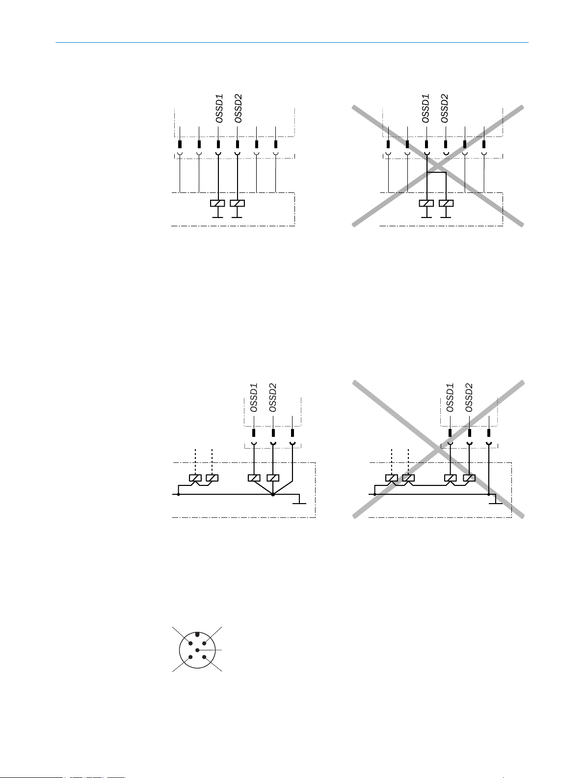
Example: Isolated connection of OSSD1 and OSSD2
Figure 26: Dual-channel and isolated connection of OSSD1 and OSSD2
Avoiding any potential difference between load and protective device
If y
•
then also switch if controlled with negative voltage (e.g., electro-mechanical con‐
tactor without reverse polarity protection diode), you must connect the 0 V connec‐
tions of these loads and those of the corresponding protective device individually
and directly to the same 0 V terminal strip. In the event of a fault, this is the only
way to ensure that there can be no potential difference between the 0 V connec‐
tions of the loads and those of the corresponding protective device.
ou connect loads to the output signal switching devices (safety outputs) that
Figure 27: No potential difference between load and protective device
Further topics
"Int
•
egration in electrical control", page 23
6.2 System connection (M12, 5-pin)
Figure 28: System connection (M12, 5-pin)
42
O PE R AT I NG IN S TR U CT I ON S | deTec4 Core 8014253/ZOH3/2017-08-04 | SICK
Subject to change without notice
Page 43

ELECTRICAL INSTALLATION 6
Table 4: System connection pin assignment (M12, 5-pin)
Pin Wire color
1 Brown +24 V DC (
2 White Reserved OSSD1 (output signal
3 Blue 0 V DC (power supply input) 0 V DC (power supply input)
4 Black Reserved OSSD2 (output signal
5 Gray Not yet assigned Not yet assigned
s S
ender r Receiver
power supply
input)
+24 V DC (power supply
input)
switching device 1)
switching device 2)
Connection diagram for the electrical installation: see "Int
egration in electrical control",
page 23.
6.3 System connection via connection cable (M12, 5-pin to 8-pin)
An optional connection cable is available to connect the 5-pin system connection to an
e
xisting 8-pin female connector. The connection cable can be used to replace an exist‐
ing C4000 safety light curtain with a deTec4 Core, without having to route new cables.
8014253/ZOH3/2017-08-04 | SICK O P ER A TI N G I NS T RU C TI O NS | deTec4 Core
Subject to change without notice
43
Page 44

OMMISSIONING
7 C
7 Commissioning
7.1 Safety
Important information
DANGER
H
azard due to lack of effectiveness of the protective device
When changes are made to the machine, the effectiveness of the protective device may
be affected unintentionally.
After every change to the machine and changes to the integration or operational
b
and secondary conditions of the safety light curtain, check the protective device
for effectiveness and recommission as specified in this chapter.
DANGER
Dangerous state of the machine
Make sure that the dangerous state of the machine is (and remains) switched off
b
during mounting, electrical installation, and commissioning.
Make sure that the outputs of the safety light curtain do not affect the machine
b
during mounting, electrical installation, and commissioning.
DANGER
azard due to lack of effectiveness of the protective device
H
Before commissioning the machine, make sure that the machine is first checked
b
and released by qualified safety personnel.
Only operate the machine with a perfectly functioning protective device.
b
DANGER
H
azard due to lack of effectiveness of the protective device
Persons and parts of the body to be protected may not be recognized in case of nonobservance.
Make sure that the optical properties of the front screens of the sender and
b
receiver are not changed, e.g., by:
beading water, mist, frost, or ice formation. If applicable, remove films or
°
other types of contamination, disconnect the voltage supply of the receiver
and then switch it back on.
Scratches or damage. Replace the device whose front screen is scratched or
°
damaged.
Make sure that all reflective surfaces and objects maintain a minimum distance
b
from the protective field.
Make sure that no dispersive media (e.g., dust, fog, or smoke) are within the calcu‐
b
lated minimum distance from the protective field.
44
Further topics
"Minimum dis
•
O PE R AT I NG IN S TR U CT I ON S | deTec4 Core 8014253/ZOH3/2017-08-04 | SICK
tance to reflective surfaces", page 21
Subject to change without notice
Page 45

7.2 Overview
Prerequisites
Further topics
7.3 Switching on
Overview
Af
sender and receiver briefly light up. After initialization, the receiver displays the align‐
ment quality using four blue light emitting diodes. Once the safety light beam curtain is
aligned (OSSD LED: green), the alignment display switches off after a certain period of
time, and only the PWR LED of the sender and the OSSD LED of the receiver continue
to light up.
COMMISSIONING 7
he projection has been correctly completed
T
•
The assembly has been correctly completed
•
The electrical installation has been completed correctly
•
"Project planning", page 17
•
"Mounting", page 31
•
"Electrical installation", page 41
•
ter switching on, the sender and receiver initialize. All light emitting diodes of the
In the event of a fault, the red fault light emitting diode flashes on the respective
device. The red fault light emitting diode in combination with the blue light emitting
diodes show the cause of the fault on the side of the receiver.
Further topics
"T
roubleshooting", page 53
•
7.4 Alignment of the sender and receiver
Overview
Af
ter mounting and electrical installation, the sender and receiver must be aligned with
each other.
Important information
DANGER
D
angerous state of the machine
Make sure that the dangerous state of the machine is (and remains) switched off
b
during the alignment process.
Make sure that the outputs of the safety light curtain do not affect the machine
b
during the alignment process.
Further topics
gnment with the QuickFix bracket", page 47
"Ali
•
"Alignment with the FlexFix bracket or with the upgrade bracket", page 47
•
"Indication of the alignment quality", page 48
•
"Diagnostic LEDs", page 53
•
8014253/ZOH3/2017-08-04 | SICK O P ER A TI N G I NS T RU C TI O NS | deTec4 Core
Subject to change without notice
45
Page 46

7 C
OMMISSIONING
7.4.1 Aligning the sender and receiver
Important information
DANGER
Dangerous state of the machine
Make sure that the dangerous state of the machine is (and remains) switched off
b
during the alignment process.
Make sure that the outputs of the safety light curtain do not affect the machine
b
during the alignment process.
Prerequisites
S
ender and receiver have been correctly mounted
•
Approach
1. Switch on the voltage supply for the safety light curtain.
2. Roughly align the sender with the receiver: Rotate the sender so that it is pointing
toward the receiver.
3. Align the receiver with the sender: Rotate the receiver so that as many blue align‐
ment quality light emitting diodes as possible light up on the receiver.
4. If required, align the sender more precisely with the receiver so that as many align‐
ment quality light emitting diodes as possible light up on the receiver.
5. If required, align the receiver more precisely with the sender so that as many align‐
ment quality light emitting diodes as possible light up on the receiver.
6. When at least three (preferably four) alignment quality light emitting diodes light
up on the receiver, fasten the components in the brackets. Torque: 2.5 Nm ...
3 Nm.
7. Switch the voltage supply off and then on again.
8. Check the alignment quality light emitting diodes to make sure that the compo‐
nents are still correctly aligned with each other.
NOTE
Once 3 blue ali
availability is stable.
Please note that body parts or objects in the protective field (e.g., hand, tool, AR60
optional laser alignment aid) may impair the function of the alignment quality LEDs.
Remove all objects from the protective field to allow the alignment quality to be
assessed.
Complementary information
T
he AR60 optional laser alignment aid can be used for alignment.
Since the AR60 optional laser alignment aid is placed in the protective field of the
safety light curtain with the adapter, a maximum of two blue alignment quality LEDs
light up and the OSSD LED lights up red. To check whether the OSSD LED of the
receiver lights up green, remove the AR60 laser alignment aid.
Further topics
"Indic
•
"Mounting", page 31
•
"Accessories", page 64
•
gnment quality light emitting diodes light up, alignment is good and
ation of the alignment quality", page 48
46
O PE R AT I NG IN S TR U CT I ON S | deTec4 Core 8014253/ZOH3/2017-08-04 | SICK
Subject to change without notice
Page 47
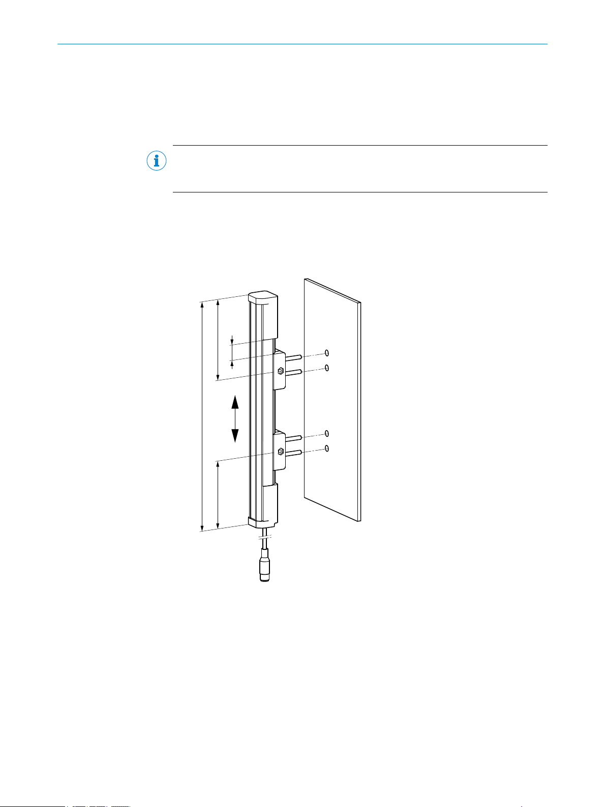
7.4.2 Alignment with the QuickFix bracket
*) Exception for protective field height 300 mm
H
≤ L
/4*
L
≤ L /4
Prerequisites
T
he sender and receiver are mounted with a QuickFix bracket
•
Important information
NOTE
If the alignment cannot be adjusted with the QuickFix bracket, use the optional FlexFix
bracket.
Alignment with the QuickFix bracket
T
he QuickFix bracket offers you the following adjustment options for aligning the sender
and receiver with each other:
Adjust vertically (H)
•
COMMISSIONING 7
Figure 29: QuickFix bracket: adjust vertically
7.4.3 Alignment with the FlexFix bracket or with the upgrade bracket
Prerequisites
A F
•
lexFix bracket or upgrade bracket is used to mount the sender and receiver.
Alignment with the FlexFix bracket or the upgrade bracket
8014253/ZOH3/2017-08-04 | SICK O P ER A TI N G I NS T RU C TI O NS | deTec4 Core
Subject to change without notice
The FlexFix bracket or upgrade bracket offer you the following adjustment options for
aligning the sender and receiver with each other:
Adjust vertically (H)
•
Rotate (± 15°)
•
47
Page 48
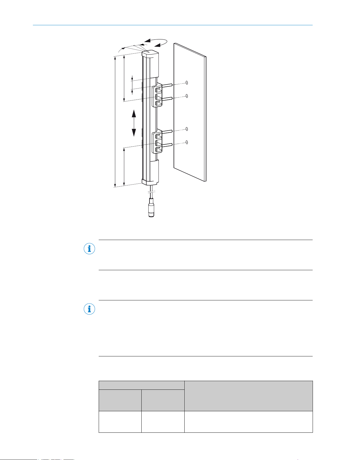
*) Exception for protective field height 300 mm
H
≤ L
/4*
L
≤ L /4
± 15°
7 COMMISSIONING
Figure 30: FlexFix bracket: adjust vertically/rotate
NOTE
R
ecommendation for aligning a long device so that it rotates uniformly in both brackets:
Grab the alignment device roughly in the center between the two brackets.
b
7.4.4 Indication of the alignment quality
Important information
NOTE
Once 3 blue ali
availability is stable.
gnment quality light emitting diodes light up, alignment is good and
Please note that body parts or objects in the protective field (e.g., hand, tool, AR60
optional laser alignment aid) may impair the function of the alignment quality LEDs.
Remove all objects from the protective field to allow the alignment quality to be
assessed.
48
O PE R AT I NG IN S TR U CT I ON S | deTec4 Core 8014253/ZOH3/2017-08-04 | SICK
Indication of the alignment quality
T
able 5: Indication of the alignment quality
LEDs Meaning
Alignment qual‐
it
y light emitting
diodes
No light emitting
diode lights up
OSSD
O R
ed
Alignment is insufficient or the protective field is inter‐
upted at least partially. The receiver cannot synchronize
r
with the sender.
Subject to change without notice
Page 49

LEDs Meaning
Alignment qual‐
it
y light emitting
OSSD
diodes
1 light emitting
diode lights up
2 light emitting
diodes light up
2 light emitting
O R
O R
O Gr
ed
ed
een
Alignment is insufficient or the protective field is inter‐
upted at least partially.
r
Alignment is insufficient or the protective field is inter‐
upted at least partially.
r
Alignment is not yet sufficient for stable availability.
diodes light up
3 light emitting
s light up
diode
4 light emitting
s light up
diode
1)
If the protective fields are very wide, there is a possibility that all four alignment quality LEDs will not light
up even when alignment is good.
O Gr
O Gr
een
een
Alignment is good, stable availability.
Alignment is very good.
7.5 Check during commissioning and modifications
The check must detect if it is possible to enter the hazardous area without being
tected.
de
COMMISSIONING 7
1)
C
arry out the checks according to the instructions from the manufacturer of the
b
machine and from the operating entity.
8014253/ZOH3/2017-08-04 | SICK O P ER A TI N G I NS T RU C TI O NS | deTec4 Core
Subject to change without notice
49
Page 50

8 O
PERATION
8 Operation
8.1 Safety
DANGER
H
azard due to lack of effectiveness of the protective device
Persons and parts of the body to be protected may not be recognized in case of nonobservance.
Maintenance work, alignment work, fault diagnoses, and any changes to the inte‐
b
gration of the protective device in the machine must only be carried out by quali‐
fied personnel.
The effectiveness of the protective device must be checked following such work.
b
DANGER
H
azard due to lack of effectiveness of the protective device
Persons and parts of the body to be protected may not be recognized in case of nonobservance.
Make sure that the optical properties of the front screens of the sender and
b
receiver are not changed, e.g., by:
beading water, mist, frost, or ice formation. If applicable, remove films or
°
other types of contamination, disconnect the voltage supply of the receiver
and then switch it back on.
Scratches or damage. Replace the device whose front screen is scratched or
°
damaged.
Make sure that all reflective surfaces and objects maintain a minimum distance
b
from the protective field.
Make sure that no dispersive media (e.g., dust, fog, or smoke) are within the calcu‐
b
lated minimum distance from the protective field.
NOTE
This document does not provide information on operating the machine in which the
safety light curtain is integrated.
Further topics
"Minimum dis
•
8.2 Regular thorough check
The check must detect if it is possible to enter the hazardous area without being
de
tected. Such possibilities may exist due to modifications, manipulations or external
influences.
C
arry out the checks according to the instructions from the manufacturer of the
b
machine and from the operating entity.
tance to reflective surfaces", page 21
50
O PE R AT I NG IN S TR U CT I ON S | deTec4 Core 8014253/ZOH3/2017-08-04 | SICK
Subject to change without notice
Page 51

9 Maintenance
The safety light curtain is maintenance-free. Depending on the ambient conditions, reg‐
ular c
9.1 safety
DANGER
H
azard due to lack of effectiveness of the protective device
Persons and parts of the body to be protected may not be recognized in case of nonobservance.
Do not do repair work on device components.
b
Do not make changes to or manipulate device components.
b
Apart from the procedures described in this document, the device components
b
must not be opened.
9.2 Regular cleaning
Overview
MAINTENANCE 9
leaning is required.
D
epending on the ambient conditions of the safety light curtain, the front screens must
be cleaned regularly and in the event of contamination. Static charges can cause dust
particles to be attracted to the front screen. The weld spark guard and deflector mirrors
must be cleaned regularly and in the event of contamination.
Important information
DANGER
H
azard due to lack of effectiveness of the protective device
Persons and parts of the body to be protected may not be recognized in case of non-
observance.
Regularly check the degree of contamination on all components based on the
b
application conditions.
Observe the information concerning test rod testing.
b
DANGER
H
azard due to lack of effectiveness of the protective device
Persons and parts of the body to be protected may not be recognized in case of non-
observance.
Make sure that the optical properties of the front screens of the sender and
b
receiver are not changed, e.g., by:
beading water, mist, frost, or ice formation. If applicable, remove films or
°
other types of contamination, disconnect the voltage supply of the receiver
and then switch it back on.
Scratches or damage. Replace the device whose front screen is scratched or
°
damaged.
Make sure that all reflective surfaces and objects maintain a minimum distance
b
from the protective field.
Make sure that no dispersive media (e.g., dust, fog, or smoke) are within the calcu‐
b
lated minimum distance from the protective field.
8014253/ZOH3/2017-08-04 | SICK O P ER A TI N G I NS T RU C TI O NS | deTec4 Core
Subject to change without notice
51
Page 52

9 MAINTENANCE
DANGER
azard due to unexpected starting of the machine
H
Make sure that the dangerous state of the machine is and remains switched off
b
during the cleaning.
Make sure that the outputs of the safety light curtain do not affect the machine
b
during the cleaning process.
NOTICE
D
o not use any aggressive cleaning agents.
b
Do not use any abrasive cleaning agents.
b
We recommend anti-static cleaning agents.
b
We recommend the use of anti-static plastic cleaner (SICK part number 5600006)
b
and the SICK lens cloth (SICK part number 4003353).
Approach
Remove dust from the front screen using a soft, clean brush.
1.
2. Then wipe the front screen with a clean, damp cloth.
3. Check the position of the sender and receiver after cleaning.
4. Check the effectiveness of the protective device.
Further topics
"Operation", page 50
•
"Minimum distance to reflective surfaces", page 21
•
9.3 Regular thorough check
The check must detect if it is possible to enter the hazardous area without being
de
tected. Such possibilities may exist due to modifications, manipulations or external
influences.
C
arry out the checks according to the instructions from the manufacturer of the
b
machine and from the operating entity.
52
O PE R AT I NG IN S TR U CT I ON S | deTec4 Core 8014253/ZOH3/2017-08-04 | SICK
Subject to change without notice
Page 53

10 Troubleshooting
This chapter describes how you identify and remedy faults that interrupt the function of
he safety light curtain.
t
10.1 Safety
DANGER
H
azard due to lack of effectiveness of the protective device
Persons and parts of the body to be protected may not be recognized in case of non-
observance.
Immediately shut the machine down if the behavior of the machine cannot be
b
clearly identified.
Immediately put the machine out of operation if you cannot clearly identify or allo‐
b
cate the fault and if you cannot safely remedy the fault.
Secure the machine so that it cannot switch on unintentionally.
b
DANGER
H
azard due to unexpected starting of the machine
TROUBLESHOOTING 10
b
DANGER
H
azard due to lack of effectiveness of the protective device
Persons and parts of the body to be protected may not be recognized in case of non-
observance.
b
b
b
NOTE
If you cannot remedy the fault with the help of the information provided in this chapter,
please contact your respective SICK subsidiary.
10.2 Diagnostic LEDs
10.2.1 Fault indicators
Overview
When any work is taking place, use the protective device to secure the machine or
to ensure that the machine is not switched on unintentionally.
Do not do repair work on device components.
Do not make changes to or manipulate device components.
Apart from the procedures described in this document, the device components
must not be opened.
In t
he event of a fault, the type of fault is indicated by the LED display on the sender or
receiver.
Sender
Position of light emitting diodes: see "Sender indicators", page 13.
8014253/ZOH3/2017-08-04 | SICK O P ER A TI N G I NS T RU C TI O NS | deTec4 Core
Subject to change without notice
53
Page 54

10 TROUBLESHOOTING
Table 6: Fault indicator on the sender
PWR LED (yel‐
lo
o o
o Ö
O Ö
Ö Ö
w)
ERR LED (red) Possible cause Rectification
No operating voltage or
ating voltage is too low
oper
or internal fault
Chec
b
k the voltage
supply, see "Technical
data", page 57.
Switch the voltage
b
supply off and then
on again.
If the fault persists,
b
replace the sender,
see "Ordering infor‐
mation", page 63.
Chec
The voltage was too high
when oper
ating the sender.
b
k the voltage
supply, see "Technical
data", page 57.
Replace the sender,
b
see "Ordering infor‐
mation", page 63.
Fault in the supply voltage
Check the voltage
b
supply and the power
supply unit, see
"Technical data",
page 57.
Switch the voltage
b
supply off and then
on again.
If the fault persists,
b
replace the defective
components, see
"Ordering informa‐
tion", page 63.
The sender identified an
ernal fault.
int
S
witch the voltage
b
supply off and then
on again.
If the fault persists,
b
replace the sender,
see "Ordering infor‐
mation", page 63.
54
o LED of
f. Ö LED flashes. O LED illuminates.
Receiver
P
osition of light emitting diodes: see "Receiver indicators", page 14.
Table 7: Fault indicator on the receiver
LEDs
OSSD
(r
ed)
O Ö Öooo
O PE R AT I NG IN S TR U CT I ON S | deTec4 Core 8014253/ZOH3/2017-08-04 | SICK
ERR
(red)
LED 1 2 3 4
(blue)
Possible cause Rectification
An internal fault has occur‐
red.
S
witch the voltage
b
supply off and then
on again.
If the fault persists,
b
replace the receiver,
see "Ordering infor‐
mation", page 63.
Subject to change without notice
Page 55

LEDs
O Ö oÖoo
O Ö ooÖo
O Ö oooÖ
TROUBLESHOOTING 10
Fault in the supply voltage
The receiver has recog‐
zed beams from several
ni
senders.
A fault or unexpected state
as identified on the
w
OSSDs of the system con‐
nection (e. g., over voltage,
short-circuit to HIGH or
short-circuit to LOW, crosscircuit, permissible load
capacity exceeded)
Chec
b
k the voltage
supply and the power
supply unit, see
"Technical data",
page 57.
Switch the voltage
b
supply off and then
on again.
If the fault persists,
b
replace the receiver,
see "Ordering infor‐
mation", page 63.
Chec
b
k the distance to
senders of the same
type. Make sure that
beams from another
sender cannot hit the
receiver, see "Protec‐
tion against interfer‐
ence from systems in
close proximity to
each other", page 22.
Switch the voltage
b
supply off and then
on again.
Chec
b
k the system wir‐
ing for a fault. Make
sure that the OSSDs
have been wired cor‐
rectly, see "Integra‐
tion in electrical con‐
trol", page 23.
Switch the voltage
b
supply off and then
on again.
If the fault persists,
b
replace the defective
components, see
"Ordering informa‐
tion", page 63.
o LED of
8014253/ZOH3/2017-08-04 | SICK O P ER A TI N G I NS T RU C TI O NS | deTec4 Core
Subject to change without notice
f. Ö LED flashes. O LED illuminates.
55
Page 56

11 DECOMMISSIONING
11 Decommissioning
11.1 Protection of the environment
The safety light curtain has been designed to minimize its impact on the environment. It
s only minimum of power and natural resources.
use
Always act in an environmentally responsible manner at work. Please note the fol‐
b
lowing information regarding disposal.
11.2 Disposal
Always dispose of serviceableness devices in compliance with local/national rules and
r
egulations with respect to waste disposal.
NOTE
W
e will be glad to help you dispose of these devices on request.
56
O PE R AT I NG IN S TR U CT I ON S | deTec4 Core 8014253/ZOH3/2017-08-04 | SICK
Subject to change without notice
Page 57

12 Technical data
12.1 Data sheet
Table 8: General system data
Protective field height, depending on
ype
t
Resolution (detection capability),
dependin
Protective field width
Resolution 14 mm
Resolution 30 mm
Protection class
Enclosure rating IP65 (IEC 60529)
Supply Voltage U
he device 3)
on t
Residual ripple
Synchronization Optical
Type Type 4 (IEC 61496-1)
Category Category 4 (ISO 13849-1)
Performance level
Safety integrity level
SIL claim limit
PFHd (mean probability of a danger‐
ous f
ailure per hour)
TM (Mis
Safe state when a fault occurs At least one OSSD is in the OFF state.
Power-up delay of sender and
eceiver before ready
r
1)
If the protective fields are very wide, there is a possibility that all four alignment quality LEDs will not light
up e
2)
Safety extra-low voltage SELV/PELV
3)
The external voltage supply must jumper a brief power failure of 20 ms as specified in IEC 60204-1. Suit‐
able power supply units are available as accessories from SICK.
4)
A fuse rated maximum 2 A shall be installed in the isolated 24 V DC power supply circuit to the device in
order to limit the available current.
5)
Within the limits of U
6)
For more detailed information on the exact configuration of your machine, please consult your respective
SIC
Minimum Typical Maximum
300 mm to 2,100 mm, 150-mm steps
14 mm or 30 mm
g on type
1)
0 m … 8 m
0 m … 12 m
2)
V
4)
5)
6)
6)
6)
III (IEC 61140)
C 60529)
IP67 (IE
19.2 V 24 V 28.8 V
PL e (ISO 13849-1)
SIL3 (IEC 61508)
SILCL3 (IEC 62061)
3.7 × 10
-9
sion Time) 20 years (ISO 13849-1)
ven when alignment is good.
V
K subsidiary.
TECHNICAL DATA 12
0 m … 10 m
0 m ... 15 m
± 10%
2 s
Table 9: Technical specifications, sender
Minimum Typical Maximum
Wavelength of sender Near-infrared
(NIR
), invisible
Weight Depending on the protective field height, see "T
weights", page 60
8014253/ZOH3/2017-08-04 | SICK O P ER A TI N G I NS T RU C TI O NS | deTec4 Core
Subject to change without notice
able of
57
Page 58

12 TECHNICAL DATA
Table 10: Technical specifications, receiver
Minimum Typical Maximum
Output signal switching devices
(OS
SDs)
2 PNP semiconductors, short-circuit protected 1), crosscircuit monitored
Response time "Response time", page 59
Duration of OFF state 100 ms
Switch-on delay 3 × response
ime
t
ON state, switching voltage HIGH
2)
(U
)
rms
UV –2.25 V 24 V U
V
OFF state, switching voltage LOW 2) 3)0 V 0 V 2.0 V
Current-carrying capacity of the
SSDs
O
300 mA each
Leakage current of the OSSDs 2 mA each
Load capacity 2.2 µF
Load inductance 2.2 H
Test pulse data
Test pulse range 150 µs
5)
6)
300 µs
Test pulse rate 3 1/s 5 1/s 10 1/s
Permissible conductor resistance
between device and load
Supply cable
1)
Applies to the voltage range between -30 V and +30 V.
2)
According to IEC 61131-2.
3)
The specified values are the switching voltage passed to the safety light curtain. If higher voltages are
pressed from the outside, the maximum value of 2.0 V may be exceeded.
im
4)
Applies to devices marked “(Rev. 1)” on the “Ident No.” type label entry. For devices not marked “(Rev.
1)”, the following applies: Load capacity (maximum) = 30 nF.
5)
When active, the outputs are tested cyclically (brief LOW). When selecting the downstream controllers,
make sure that the test signals do not result in deactivation when using the above parameters.
6)
Applies to devices marked “(Rev. 1)” on the “Ident No.” type label entry. For devices not marked “(Rev.
1)”, the following applies: Test pulse width (typical) = 300 µs; test pulse width (maximum) = 350 µs.
7)
Make sure to limit the individual conductor resistance to the downstream controller to this value to
ensure that a cross-circuit between the outputs is safely detected. (Also observe IEC 60204-1.)
8)
The supply cable must not be used to connect other loads with the exception of the sender.
8)
7)
2.5 Ω
1 Ω
4)
6)
58
Table 11: Operating data
Minimum Typical Maximum
Connection Plug, M12, 5-pin
Length of cable
.g. wire cross-section 0.34 mm²,
e
1)
50 m
15 m
copper cable
e.g. wire cross-section 0.5 mm²,
copper cable
30 m
Ambient operating temperature 2) 3)-30°C +55°C
Air humidity (non-condensing) 15% 95%
Storage temperature -30°C +70°C
Housing cross section 31 mm × 34 mm, plus bracket, see "Dimensional dr
aw‐
ings", page 61
Vibration resistance
O PE R AT I NG IN S TR U CT I ON S | deTec4 Core 8014253/ZOH3/2017-08-04 | SICK
4)
5 g, 10 Hz … 55 Hz (IEC 60068-2-6)
Subject to change without notice
Page 59

Shock resistance
1)
2)
3)
4)
5)
12.2 Response time
Overview
he response time is subject to the following parameters:
T
•
•
Table 12: Response time dependent on the protective field height
Protective field height in mm Response time in ms
300 11 10
450 12 10
600 13 10
750 13 11
900 14 11
1050 15 11
1200 16 12
1350 17 12
1500 18 13
1650 19 13
1800 20 13
1950 21 14
2100 22 14
TECHNICAL DATA 12
Minimum Typical Maximum
5)
Maximum permissible conductor resistances must be observed.
The temperature difference between sender and receiver must not exceed 25 K.
The cable belonging to the device incl. the associated connection plug must not be flexibly mounted
under –25° C
Test conditions per axis: 1 octave/minute, amplitude: 0.35 mm, 20 sweeps.
Test conditions per axis: 500 shocks.
.
Resolution
Protective field height
10 g, 16 ms (IEC 60068-2-27)
Resolution 14 mm Resolution 30 mm
12.3 Power consumption
Table 13: Power consumption, sender and receiver
Protective field
hei
ght in mm
300 0.96 0.82 1.92 1.63
450 1.08 0.86 2.16 1.73
600 1.20 0.91 2.40 1.82
750 1.32 0.96 2.64 1.92
900 1.44 1.01 2.88 2.02
1050 1.56 1.06 3.12 2.11
1200 1.68 1.10 3.36 2.21
1350 1.80 1.15 3.60 2.30
1500 1.92 1.20 3.84 2.40
8014253/ZOH3/2017-08-04 | SICK O P ER A TI N G I NS T RU C TI O NS | deTec4 Core
Subject to change without notice
Typical power consumption of
sender in W
Resolution
14 mm
Resolution
30 mm
Typical power consumption of
receiver in W
Resolution
14 mm
1)
Resolution
30 mm
59
Page 60
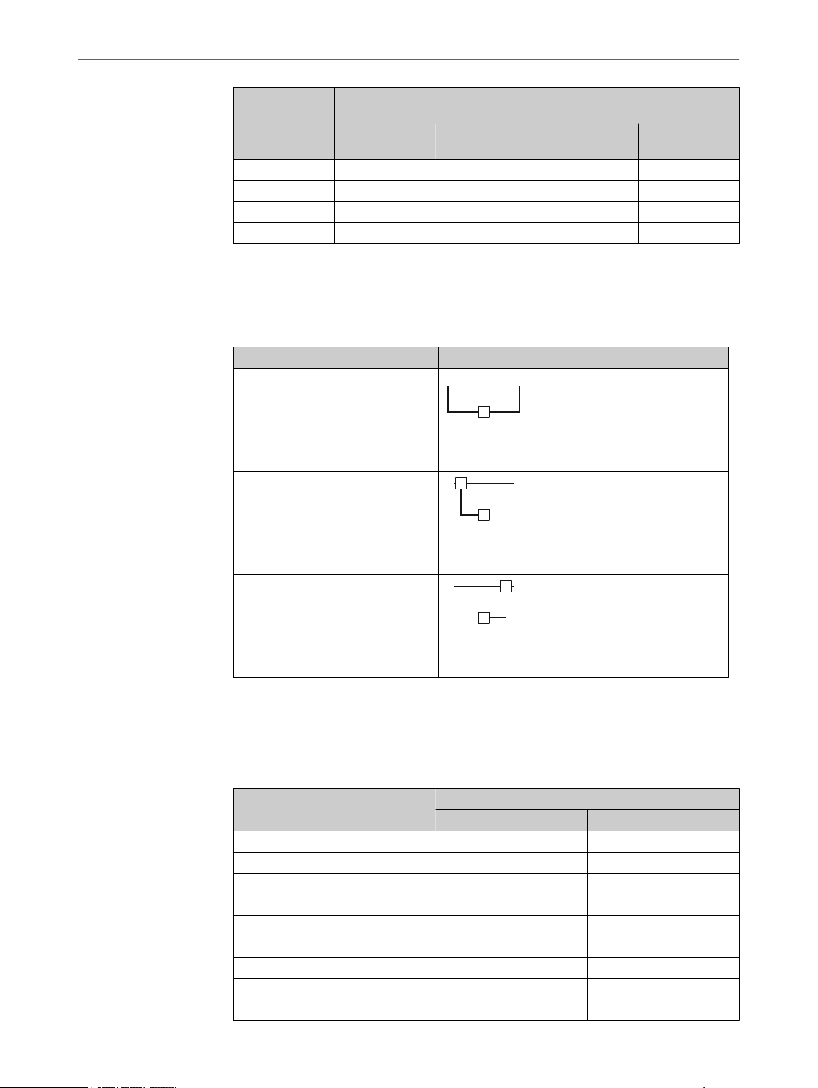
r
s
b c
S
r
s
r
s
a
T
c
S
r
s
r
s
a
T
b
S
r
s
12 TECHNICAL DATA
Protective field
hei
1650 2.04 1.25 4.08 2.50
1800 2.16 1.30 4.32 2.59
1950 2.28 1.34 4.56 2.69
2100 2.40 1.39 4.80 2.78
1)
Power discharged again via the OSSDs depending on the connected OSSD load must be added to the
table values.
12.4 Length of cable
Table 14: Maximum lengths of cable for wire cross-section 0.34 mm2, c
Separate connecting cables for
sender and r
Connection of sender and receiver
ia T-connector on the sender
v
ght in mm
Typical power consumption of
sender in W
Resolution
14 mm
eceiver
Typical power consumption of
receiver in W
Resolution
30 mm
Single system
b ≤ 85 m c ≤ 15 m
Resolution
14 mm
1)
opper wire
Resolution
30 mm
Connection of sender and receiver
ia T-connector on the receiver
v
S Control cabinet with safety relay or safety controller
T T-connector
12.5 Table of weights
Table 15: Weight of sender and receiver
Protective field height in mm Weight in g
300 290 300
450 430 440
600 570 580
750 700 710
900 840 850
1050 970 980
1200 1110 1120
1350 1240 1250
1500 1380 1390
a + c ≤ 15 m
a ≤ 15 m b ≤ 85 m
1)
ender r Receiver
s S
60
O PE R AT I NG IN S TR U CT I ON S | deTec4 Core 8014253/ZOH3/2017-08-04 | SICK
Subject to change without notice
Page 61
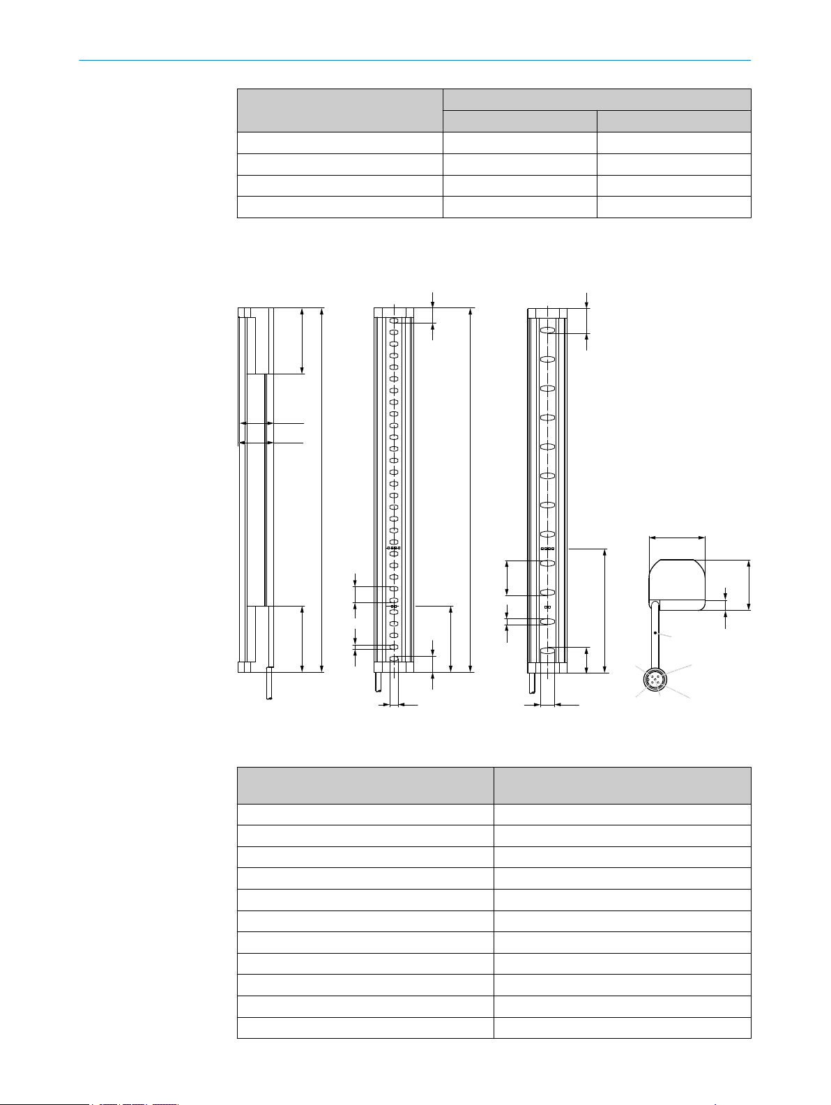
5
30
4
14
56,8
56,8
L
56,8
L
29,5
30,7
7 12
30,7
6,3
34
L=150
106,8
1
4
2
5
3
13
21,1
13,8
21,8
TECHNICAL DATA 12
Protective field height in mm Weight in g
1650 1510 1520
1800 1650 1660
1950 1790 1800
2100 1920 1930
1)
Tolerance: ± 50 g.
12.6 Dimensional drawings
1)
s S
ender r Receiver
Figure 31: Dimensional drawing, sender and receiver
Table 16: Dimensions based on the protective field height, sender and receiver
Protective field height, nominal in mm Protective field height, effective = dimension L
in mm
1)
300 313
450 463
600 613
750 763
900 913
1050 1063
1200 1213
1350 1362
8014253/ZOH3/2017-08-04 | SICK O P ER A TI N G I NS T RU C TI O NS | deTec4 Core
Subject to change without notice
1500 1512
1650 1662
1800 1812
61
Page 62

12 T
ECHNICAL DATA
Protective field height, nominal in mm Protective field height, effective = dimension L
in mm
1)
1950 1962
2100 2112
1)
The effective protective field corresponds to the entire length of the housing. The test object defined in
t
he standard IEC 61496-1 is recognized over the entire length of the housing. The limits of the protective
field are identical to ends of the housing.
62
O PE R AT I NG IN S TR U CT I ON S | deTec4 Core 8014253/ZOH3/2017-08-04 | SICK
Subject to change without notice
Page 63

13 Ordering information
13.1 Scope of delivery
Scope of delivery, sender
ender
S
•
Scope of delivery, receiver
Receiver
•
Test rod with diameter corresponding to the resolution of the safety light curtain
•
Safety note
•
Mounting instructions
•
Operating instructions for download: www.sick.com
•
13.2 Ordering information deTec4 Core
Table 17: Ordering information deTec4 Core, resolution 14 mm
Protective field
height in mm
300 1211450 C4C-SA03010A10000 1211463 C4C-EA03010A10000
450 1211469 C4C-SA04510A10000 1211470 C4C-EA04510A10000
600 1211471 C4C-SA06010A10000 1211472 C4C-EA06010A10000
750 1211473 C4C-SA07510A10000 1211474 C4C-EA07510A10000
900 1211475 C4C-SA09010A10000 1211515 C4C-EA09010A10000
1050 1211476 C4C-SA10510A10000 1211477 C4C-EA10510A10000
1200 1211478 C4C-SA12010A10000 1211479 C4C-EA12010A10000
1350 1211480 C4C-SA13510A10000 1211481 C4C-EA13510A10000
1500 1211482 C4C-SA15010A10000 1211483 C4C-EA15010A10000
1650 1211484 C4C-SA16510A10000 1211485 C4C-EA16510A10000
1800 1211486 C4C-SA18010A10000 1211487 C4C-EA18010A10000
1950 1211488 C4C-SA19510A10000 1211489 C4C-EA19510A10000
2100 1211490 C4C-SA21010A10000 1211491 C4C-EA21010A10000
Part number Type code Part number Type code
ORDERING INFORMATION 13
s S
ender r Receiver
Table 18: Ordering information deTec4 Core, resolution 30 mm
Protective field
hei
ght in mm
300 1211462 C4C-SA03030A10000 1211464 C4C-EA03030A10000
450 1211492 C4C-SA04530A10000 1211493 C4C-EA04530A10000
600 1211494 C4C-SA06030A10000 1211495 C4C-EA06030A10000
750 1211496 C4C-SA07530A10000 1211497 C4C-EA07530A10000
900 1211498 C4C-SA09030A10000 1211516 C4C-EA09030A10000
1050 1211499 C4C-SA10530A10000 1211500 C4C-EA10530A10000
1200 1211501 C4C-SA12030A10000 1211502 C4C-EA12030A10000
1350 1211503 C4C-SA13530A10000 1211504 C4C-EA13530A10000
1500 1211505 C4C-SA15030A10000 1211506 C4C-EA15030A10000
1650 1211507 C4C-SA16530A10000 1211508 C4C-EA16530A10000
1800 1211509 C4C-SA18030A10000 1211510 C4C-EA18030A10000
1950 1211511 C4C-SA19530A10000 1211512 C4C-EA19530A10000
2100 1211513 C4C-SA21030A10000 1211514 C4C-EA21030A10000
8014253/ZOH3/2017-08-04 | SICK O P ER A TI N G I NS T RU C TI O NS | deTec4 Core
Subject to change without notice
Part number Type code Part number Type code
s S
ender r Receiver
63
Page 64

14 A
CCESSORIES
14 Accessories
14.1 Brackets
Table 19: Brackets ordering information
Part Type code Part number
QuickFix bracket (2x) BEF-3SHABPKU2 2066048
FlexFix bracket (4x) BEF-1SHABPKU4 2066614
FlexFix mounting kit (2x FlexFix brackets, align‐
ment t
tion in device columns)
Stainless steel support bracket BEF-2AAAADES2 2026849
Exchange bracket (kit with 4 brackets, mount‐
in
ets 2019649 and 2019659 or side bracket
2019506 with the FlexFix bracket when using
the bore holes provided)
QuickFix bracket
BEF-1SHABBKU2 2073543
ool, and assembly materials for installa‐
BEF-1SHABP004 2071021
g kit for replacement of swivel mount brack‐
64
Figure 32: Dimensional drawing of the QuickFix bracket (2066048)
* Width of the housing up to the depression
O PE R AT I NG IN S TR U CT I ON S | deTec4 Core 8014253/ZOH3/2017-08-04 | SICK
Subject to change without notice
Page 65

FlexFix bracket
ACCESSORIES 14
Figure 33: Dimensional drawing of the FlexFix bracket (2066614)
8014253/ZOH3/2017-08-04 | SICK O P ER A TI N G I NS T RU C TI O NS | deTec4 Core
Subject to change without notice
65
Page 66

A
B
14 ACCESSORIES
Exchange bracket
Figure 34: Dimensional drawing of the upgrade bracket (2071021)
14.2 Mounting accessories
Table 20: Mounting accessories ordering information
Part Part number
Alignment tool 4084133
66
O PE R AT I NG IN S TR U CT I ON S | deTec4 Core 8014253/ZOH3/2017-08-04 | SICK
Subject to change without notice
Page 67

14.3 Weld spark guard
1
2
3
4
Function and use
he weld spark guard can be used to protect the front screen of the safety light curtain.
T
The weld spark guard reduces the scanning range of the system by 15 %.
Ordering information
T
able 21: Weld spark guard ordering information
Part Part number
Weld spark guard 2069268
Mounting
ACCESSORIES 14
14.4 Connectors
1)
Ambient oper
ating temperature: Down to -30 °C with fixed installation.
Figure 35: Mounting the weld spark guard
Clean the front screen.
1
Remove backing film
2
Press against the weld spark guard
3
Cut off excess ends
4
Cables
able 22: Ordering information for M12 connecting cable, 5-pin (0.34 mm2)
T
Part Type code Part number
Female connector, straight, 2 m c
end
Female connector, straight, 5 m cable, open
end
Female connector, straight, 10 m c
end
Female connector, straight, 15 m cable, open
end
able, open
able, open
DOL-1205-G02MC 6025906
DOL-1205-G05MC 6025907
DOL-1205-G10MC 6025908
DOL-1205-G15MC 6051946
1)
8014253/ZOH3/2017-08-04 | SICK O P ER A TI N G I NS T RU C TI O NS | deTec4 Core
Subject to change without notice
67
Page 68

14 A
CCESSORIES
Part Type code Part number
Female connector, straight, 20 m c
end
Female connector, straight, 30 m cable, open
end
Female connector, angled, 2 m cable, open
end
Female connector, angled, 5 m cable, open
end
Female connector, angled, 10 m c
end
Table 23: Ordering information, connection cable (replacement of existing devices)
Part Type code Part number
Connection cable, M12, 5-pin to M12, 8-pin DSL-1285GM25034KM1 2070987
Connection cable, M12, 5-pin to M26, 7-pin DSL-6187GM25034KM1 2070988
Connection cable, M12, 5-pin to M26, 12-pin DSL-6182GM25034KM1 2070989
Table 24: Distributor ordering information
Part Type code Part number
T distributor, 5-pin DSC-1205T000025KM0 6030664
able, open
able, open
DOL-1205-G20MC 6050247
DOL-1205-G30MC 6050248
DOL-1205-W02MC 6025909
DOL-1205-W05MC 6025910
DOL-1205-W10MC 6025911
2)
Table 25: Resistance terminal ordering information
Part Part number
Resistance terminal, 2.15 kΩ 2073807
Table 26: Ordering information for power supply
Part Type code Part number
Output 24 V DC, 50 W (2.1 A), voltage supply
C Class 2, SELV, PELV, input
NE
120 V … 240 V AC
Output 24 V DC, 95 W (3.9 A), voltage supply
C Class 2, SELV, PELV, input
NE
100 V … 120 V/220 V … 240 V AC
14.5 Alignment aid
Table 27: Alignment aid ordering information
Part Part number
Laser alignment aid AR60 1015741
Adapter 4070854
14.6 Deflector mirrors
PS50WE24V 7028789
PS95WE24V 7028790
14.6.1 Function and use
Overview
eflector mirrors can be used to shape the protective field to secure hazardous points
D
from multiple sides using a single safety light curtain.
2)
Ambient operating temperature: Down to –30 °C with fixed installation
68
O PE R AT I NG IN S TR U CT I ON S | deTec4 Core 8014253/ZOH3/2017-08-04 | SICK
Subject to change without notice
Page 69

Figure 36: Example of use of deflector mirrors
Important information
ACCESSORIES 14
DANGER
H
azard due to lack of effectiveness of the protective device
Persons and parts of the body to be protected may not be recognized in case of nonobservance.
Only mount deflector mirrors to solid walls or machine components. The position
b
of the deflector mirrors must not change after alignment.
Do not use deflector mirrors if contamination, beading water, condensation, or
b
frost on the deflector mirrors is to be expected.
Make sure that the deflector mirrors are intact and free of scratches, contamina‐
b
tion, beading water, condensation, frost, etc. at all times.
Further topics
"Mirror columns", page 71
•
14.6.2 Mounting
To mount the deflector mirrors, use the included swivel mount brackets.
14.6.3 Change in scanning range using deflector mirrors
Overview
T
he information relates to 90° beam deflection per mirror and a protective field height
of 900 mm.
Important information
NOTE
T
he use of deflector mirrors reduces the scanning range depending on the number of
deflector mirrors in the protective field.
8014253/ZOH3/2017-08-04 | SICK O P ER A TI N G I NS T RU C TI O NS | deTec4 Core
Subject to change without notice
69
Page 70

D D D
D D
14 ACCESSORIES
Table 28: Scanning range with and without 1 or 2 deflector mirrors
Model name Resolution Scanning
ran
ge, typi‐
1)
cal
Scanning range with
1 deflector mirror, typi‐
1)
cal
Scanning range with
2 deflector mirrors, typi‐
1)
cal
PNS75, PNS125 14 mm 8 m 7.2 m 6.4 m
PNS75, PNS125 30 mm 12 m 10.7 m 9.6 m
1)
If the protective fields are very wide, there is a possibility that all four alignment quality LEDs will not light
up e
ven when alignment is good.
Example: Maximum distance when using deflector mirrors
Ma
ximum distance D between sender or receiver and mirrors or between 2 mirrors
(example applies to 90° beam deflection per mirror, protective field height 900 mm).
PNS75: D ≤ 4 m
•
PNS125: D ≤ 8 m
•
Figure 37: Maximum distance when using deflector mirrors
14.6.4 Deflector mirror PNS75 - ordering information
Table 29: Ordering information, deflector mirror PNS75
Mirror length in mm Max. protective field
340 300 PNS75-034 1019414
490 450 PNS75-049 1019415
640 600 PNS75-064 1019416
790 750 PNS75-079 1019417
940 900 PNS75-094 1019418
1090 1050 PNS75-109 1019419
1240 1200 PNS75-124 1019420
1390 1350 PNS75-139 1019421
1540 1500 PNS75-154 1019422
1690 1650 PNS75-169 1019423
1840 1800 PNS75-184 1019424
14.6.5 Deflector mirror PSN125 - ordering information
Table 30: Ordering information, deflector mirror PSN125
Mirror length in mm Max. protective field
340 300 PNS125-034 1019425
490 450 PNS125-049 1019426
640 600 PNS125-064 1019427
790 750 PNS125-079 1019428
hei
ght in mm
ght in mm
hei
Type code Part number
Type code Part number
70
O PE R AT I NG IN S TR U CT I ON S | deTec4 Core 8014253/ZOH3/2017-08-04 | SICK
Subject to change without notice
Page 71

ACCESSORIES 14
Mirror length in mm Max. protective field
hei
ght in mm
940 900 PNS125-094 1019429
1090 1050 PNS125-109 1019430
1240 1200 PNS125-124 1019431
1390 1350 PNS125-139 1019432
1540 1500 PNS125-154 1019433
1690 1650 PNS125-169 1019434
1840 1800 PNS125-184 1019435
14.7 Mirror columns and device columns
14.7.1 Mirror columns
Table 31: Ordering information for mirror columns
Column height Mirror length Type code Part number
1281.5 mm 1082 mm PM3C13-00030000 1043453
1569 mm 1382 mm PM3C15-00030000 1077525
1716.5 mm 1532 mm PM3C17-00030000 1043454
2016.5 mm 1682 mm PM3C19-00030000 1043455
2216.5 mm 1832 mm PM3C20-00030000 1043456
Type code Part number
Complementary information
Observe the information on deflector mirrors, particularly on changing the scanning
range.
Further topics
•
14.7.2 Device columns
Table 32: Ordering information for device columns
"Deflector mirrors", page 68
Column height Max. installation
gth
len
985 mm 965 mm PU3H96-00000000 2045490
1185 mm 1165 mm PU3H11-00000000 2045641
1285 mm 1265 mm PU3H13-00000000 2045642
1570 mm 1550 mm PU3H15-00000000 2068813
1740 mm 1720 mm PU3H17-00000000 2045643
2040 mm 2020 mm PU3H21-00000000 2045644
2270 mm 2250 mm PU3H22-00000000 2045645
2420 mm 2400 mm PU3H24-00000000 2045646
Type code Part number
14.8 Cleaning agent
Table 33: Cleaning agent ordering information
Part Part number
Anti-static plastic cleaner 5600006
Lens cloth 4003353
8014253/ZOH3/2017-08-04 | SICK O P ER A TI N G I NS T RU C TI O NS | deTec4 Core
Subject to change without notice
71
Page 72

14 ACCESSORIES
14.9 Test rods
Table 34: Ordering information, test rods
Part Part number
Test rod 14 mm 2022599
Test rod 30 mm 2022602
Test rod holder 2052249
72
O PE R AT I NG IN S TR U CT I ON S | deTec4 Core 8014253/ZOH3/2017-08-04 | SICK
Subject to change without notice
Page 73

15 Annex
15.1 Compliance with EU directives
EU declaration of conformity (excerpt)
he undersigned, who represents the manufacturer below, hereby declares that the
T
product complies with the regulations of the EU directive(s) below (including all relevant
changes), and that it is based on the relevant standards and/or technical specifica‐
tions.
Complete EU declaration of conformity for download
You can call up the EU declaration of conformity and the current operating instructions
for the protective device by entering the part number in the search field at
www.sick.com (part number: see the type label entry in the “Ident. no.” field).
ANNEX 15
8014253/ZOH3/2017-08-04 | SICK O P ER A TI N G I NS T RU C TI O NS | deTec4 Core
Subject to change without notice
73
Page 74

15 ANNEX
15.2 Note on specified standards
Standards are specified in this document. The table shows regional standards with sim‐
ilar or ident
Table 35: Note on specified standards
Standard Standard (regional)
IEC 60068-2-6 GB/T 2423.10
IEC 60068-2-27 GB/T 2423.5
IEC 60204-1 GB 5226.1
IEC 60529 GB 4208
IEC 60825 GB 7247.1
IEC 61131-2 GB/T 15969.1
IEC 61140 GB/T 17045
IEC 61496-1 GB/T 19436.1
IEC 61496-3 GB/T 19436.3
IEC 61508 GB/T 20438
IEC 62061 GB 28526
ISO 13849-1 GB/T 16855.1
ISO 13855 GB/T 19876
ical contents.
China
74
O PE R AT I NG IN S TR U CT I ON S | deTec4 Core 8014253/ZOH3/2017-08-04 | SICK
Subject to change without notice
Page 75

15.3 Checklist for initial commissioning and commissioning
Checklist for manufacturers or installers for installing electro-sensitive protective
vice (ESPE)
de
The details relating to the items listed below must be available no later than when the
system is commissioned for the first time. However, these depend on the specific appli‐
cation (the requirements of which must be reviewed by the manufacturer or installer).
This checklist should be retained and kept with the machine documentation to serve as
reference during recurring tests.
This checklist does not replace the initial commissioning, nor the regular inspection by
qualified safety personnel.
ANNEX 15
Have the safety rules and regulations been observed in compliance with the
dir
ectives and standards applicable to the machine?
Are the applied directives and standards listed in the declaration of conformity? Yes N
Does the protective device comply with the required PL/SIL claim limit and PFHd
in ac
cordance with EN ISO 13849-1/EN 62061 and the required type in accord‐
ance with EN 61496-1?
Is access to the hazardous area or hazardous point only possible through the
protective field of the ESPE?
Have appropriate measures been taken to protect (mechanical protection) or
or (protective devices) any persons or objects in the hazardous area when
monit
protecting a hazardous area or hazardous point, and have these devices been
secured or locked to prevent their removal?
Are additional mechanical protective measures fitted and secured against
manipulation which prevent reaching below, above or around the ESPE?
Has the maximum shutdown and/or stopping time of the machine been meas‐
ed, specified and documented (at the machine and/or in the machine docu‐
ur
mentation)?
Has the ESPE been mounted such that the required minimum distance from the
nearest hazardous point has been achieved?
Are the ESPE devices properly mounted and secured against manipulation after
adjustment?
Are the required protective measures against electric shock in effect (protection
lass)?
c
Is the control switch for resetting the protective devices (ESPE) or restarting the
machine present and correctly installed?
Are the outputs of the ESPE (OSSDs or safety outputs via the network) inte‐
grated according to the required PL/SILCL in accordance with EN ISO
13849-1/EN 62061 and does the integration correspond to the circuit dia‐
grams?
Has the protective function been checked in compliance with the test notes of
his documentation?
t
Are the specified protective functions effective at every operating mode that can
be set?
Are the switching elements activated by the ESPE, e.g. contactors, valves, moni‐
ored?
t
Is the ESPE effective over the entire period of the dangerous state? Yes No
Once initiated, will a dangerous state be stopped when switching the ESPE on or
of
f and when changing the operating mode, or when switching to another pro‐
tective device?
Yes No
o
Yes No
Yes No
Yes No
Yes No
Yes No
Yes No
Yes No
Yes No
Yes No
Yes No
Yes No
Yes No
Yes No
Yes No
8014253/ZOH3/2017-08-04 | SICK O P ER A TI N G I NS T RU C TI O NS | deTec4 Core
Subject to change without notice
75
Page 76

16 LIS
T OF FIGURES
16 List of figures
1. Sender and receiver................................................................................................... 11
2. Sender indicators....................................................................................................... 13
3. Receiver indicators.....................................................................................................14
4. Hazardous point protection........................................................................................15
5. Access protection....................................................................................................... 15
6. Hazardous area protection.........................................................................................16
7. Minimum distance to hazardous point for orthogonal (right-angled) approach to
8. Representation of the accessibility of electro-sensitive protective device by reach‐
9. Minimum distance from reflective surfaces............................................................. 21
10. Graph of minimum distance from reflective surfaces............................................. 22
11.
12.
13. Dual-channel and isolated connection of OSSD1 and OSSD2................................24
14. No potential difference between load and protective device.................................. 24
15. Schematic representation of operation with restart interlock.................................25
16. Connection diagram for UE48-2OS with restart interlock and external device moni‐
17. Test rod check: Step 1................................................................................................29
18. Test rod check: Step 2................................................................................................29
19. Sender and receiver must not be installed at 180° rotated relative to each other
20. Mounting the QuickFix bracket to a profile...............................................................35
21. Mount FlexFix brackets to a profile frame.................................................................36
22. Inserting the safety light curtain in the FlexFix brackets......................................... 37
23. Upgrade bracket, installation version A.................................................................... 39
24. Upgrade bracket, installation version B.................................................................... 39
25. Upgrade bracket, installation version C.................................................................... 40
26. Dual-channel and isolated connection of OSSD1 and OSSD2................................42
27. No potential difference between load and protective device.................................. 42
28. System connection (M12, 5-pin)............................................................................... 42
29. QuickFix bracket: adjust vertically............................................................................. 47
30. FlexFix bracket: adjust vertically/rotate.................................................................... 48
31. Dimensional drawing, sender and receiver.............................................................. 61
32. Dimensional drawing of the QuickFix bracket (2066048).......................................64
33. Dimensional drawing of the FlexFix bracket (2066614)..........................................65
34. Dimensional drawing of the upgrade bracket (2071021).......................................66
35. Mounting the weld spark guard................................................................................. 67
36. Example of use of deflector mirrors.......................................................................... 69
37. Maximum distance when using deflector mirrors....................................................70
otective field............................................................................................................ 20
pr
ing over. Left: Protective field that cannot be reached over. Right: Protective field
that can be reached over........................................................................................... 21
Preventing mutual interference from system 1 and s
Trouble-free operation due to reversed direction of transmission of system 1 and
s
ystem 2.................................................................................................................... 23
t
oring............................................................................................................................26
..................................................................................................................................... 33
ystem 2............................. 22
76
O PE R AT I NG IN S TR U CT I ON S | deTec4 Core 8014253/ZOH3/2017-08-04 | SICK
Subject to change without notice
Page 77

17 List of tables
1. Formula for calculating the minimum distance from reflective surfaces............... 22
2. Lateral and rear mounting with the QuickFix bracket.............................................. 34
3. Lateral and rear mounting with the FlexFix bracket.................................................36
4. System connection pin assignment (M12, 5-pin).................................................... 43
5. Indication of the alignment quality............................................................................48
6. Fault indicator on the sender.....................................................................................54
7. Fault indicator on the receiver...................................................................................54
8. General system data.................................................................................................. 57
9. Technical specifications, sender................................................................................57
10. Technical specifications, receiver..............................................................................58
11. Operating data............................................................................................................58
12. Response time dependent on the protective field height........................................59
13. Power consumption, sender and receiver.................................................................59
14. Maximum lengths of cable for wire cross-section 0.34 mm2, c
15. Weight of sender and receiver ..................................................................................60
16. Dimensions based on the protective field height, sender and receiver..................61
17. Ordering information deTec4 Core, resolution 14 mm.............................................63
18. Ordering information deTec4 Core, resolution 30 mm.............................................63
19. Brackets ordering information................................................................................... 64
20. Mounting accessories ordering information............................................................. 66
21. Weld spark guard ordering information.....................................................................67
22. Ordering information for M12 connecting cable, 5-pin (0.34 mm2) ...................... 67
23. Ordering information, connection cable (replacement of existing devices) .......... 68
24. Distributor ordering information................................................................................ 68
25. Resistance terminal ordering information................................................................ 68
26. Ordering information for power supply......................................................................68
27. Alignment aid ordering information...........................................................................68
28. Scanning range with and without 1 or 2 deflector mirrors...................................... 70
29. Ordering information, deflector mirror PNS75..........................................................70
30. Ordering information, deflector mirror PSN125....................................................... 70
31. Ordering information for mirror columns...................................................................71
32. Ordering information for device columns..................................................................71
33. Cleaning agent ordering information.........................................................................71
34. Ordering information, test rods..................................................................................72
35. Note on specified standards......................................................................................74
LIST OF TABLES 17
opper wire............ 60
8014253/ZOH3/2017-08-04 | SICK O P ER A TI N G I NS T RU C TI O NS | deTec4 Core
Subject to change without notice
77
Page 78

17 LIST OF TABLES
78
O PE R AT I NG IN S TR U CT I ON S | deTec4 Core 8014253/ZOH3/2017-08-04 | SICK
Subject to change without notice
Page 79

LIST OF TABLES 17
8014253/ZOH3/2017-08-04 | SICK O P ER A TI N G I NS T RU C TI O NS | deTec4 Core
Subject to change without notice
79
Page 80

Further locations at www.sick.com
Australia
Phone +61 3 9457 0600
1800 334 802 – tollfree
E-Mail sales@sick.com.au
Austria
Phone +43 22 36 62 28 8-0
E-Mail office@sick.at
Belgium/Luxembourg
Phone +32 2 466 55 66
E-Mail info@sick.be
Brazil
Phone +55 11 3215-4900
E-Mail marketing@sick.com.br
Canada
Phone +1 905 771 14 44
E-Mail information@sick.com
Czech Republic
Phone +420 2 57 91 18 50
E-Mail sick@sick.cz
Chile
Phone +56 2 2274 7430
E-Mail info@schadler.com
China
Phone +86 20 2882 3600
E-Mail info.china@sick.net.cn
Denmark
Phone +45 45 82 64 00
E-Mail sick@sick.dk
Finland
Phone +358-9-2515 800
E-Mail sick@sick.fi
France
Phone +33 1 64 62 35 00
E-Mail info@sick.fr
Germany
Phone +49 211 5301-301
E-Mail info@sick.de
Hong Kong
Phone +852 2153 6300
E-Mail ghk@sick.com.hk
Hungary
Phone +36 1 371 2680
E-Mail office@sick.hu
India
Phone +91 22 6119 8900
E-Mail info@sick-india.com
Israel
Phone +972 4 6881000
E-Mail info@sick-sensors.com
Italy
Phone +39 02 274341
E-Mail info@sick.it
Japan
Phone +81 3 5309 2112
E-Mail support@sick.jp
Malaysia
Phone +6 03 8080 7425
E-Mail enquiry.my@sick.com
Mexico
Phone +52 (472) 748 9451
E-Mail mario.garcia@sick.com
Netherlands
Phone +31 30 2044 000
E-Mail info@sick.nl
New Zealand
Phone +64 9 415 0459
0800 222 278 – tollfree
E-Mail sales@sick.co.nz
Norway
Phone +47 67 81 50 00
E-Mail sick@sick.no
Poland
Phone +48 22 539 41 00
E-Mail info@sick.pl
Romania
Phone +40 356 171 120
E-Mail office@sick.ro
Russia
Phone +7 495 775 05 30
E-Mail info@sick.ru
Singapore
Phone +65 6744 3732
E-Mail sales.gsg@sick.com
Slovakia
Phone +421 482 901201
E-Mail mail@sick-sk.sk
Slovenia
Phone +386 591 788 49
E-Mail office@sick.si
South Africa
Phone +27 11 472 3733
E-Mail info@sickautomation.co.za
South Korea
Phone +82 2 786 6321
E-Mail info@sickkorea.net
Spain
Phone +34 93 480 31 00
E-Mail info@sick.es
Sweden
Phone +46 10 110 10 00
E-Mail info@sick.se
Switzerland
Phone +41 41 619 29 39
E-Mail contact@sick.ch
Taiwan
Phone +886 2 2375-6288
E-Mail sales@sick.com.tw
Thailand
Phone +66 2645 0009
E-Mail Ronnie.Lim@sick.com
Turkey
Phone +90 216 528 50 00
E-Mail info@sick.com.tr
United Arab Emirates
Phone +971 4 88 65 878
E-Mail info@sick.ae
United Kingdom
Phone +44 1727 831121
E-Mail info@sick.co.uk
USA
Phone +1 800 325 7425
E-Mail info@sick.com
Vietnam
Phone +84 945452999
E-Mail Ngo.Duy.Linh@sick.com
8014253/ZOH3/2017-08-04/en
SICK AG | Waldkirch | Germany | www.sick.com
 Loading...