

Page 1
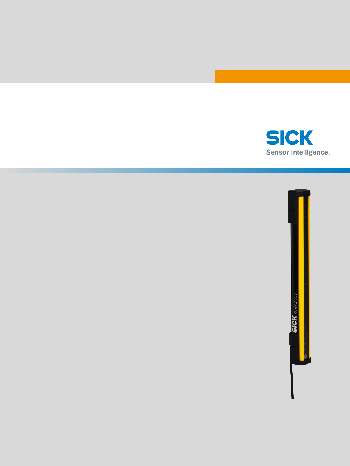
deTec2 Core
Safety light curtain
O P E R A T I N G I N S T R U C T I O N S
Page 2

Described product deTec2 Core
Manufacturer SICK AG
Erwin-Sick-Str. 1
79183 Waldkirch, Germany
Germany
Legal information This work is protected by copyright. Any rights derived from the copyright shall be re‐
served for SICK AG. Reproduction of this document or parts of this document is only
permissible within the limits of the legal determination of Copyright Law. Any modifica‐
tion, expurgation or translation of this document is prohibited without the express writ‐
ten permission of SICK AG.
The trademarks stated in this document are the property of their respective owner.
© SICK AG. All rights reserved.
Original document This document is an original document of SICK AG.
2
O PE R AT I NG IN S TR U CT I ON S | deTec2 Core 8014276/2014-02-18 | SICK
Subject to change without notice
Page 3

Contents
CONTENTS
1 About this document..............................................................................6
1.1 Scope............................................................................................................... 6
1.2 Target groups and structure of these operating instructions.......................6
1.3 Further information......................................................................................... 7
1.4 Symbols and document conventions.............................................................7
2 Safety information..................................................................................8
2.1 General safety notes....................................................................................... 8
2.2 Correct use.......................................................................................................8
2.3 Requirements for the qualification of personnel.......................................... 9
3 Product description..............................................................................10
3.1 Structure and function..................................................................................10
3.2 Product characteristics.................................................................................11
3.2.1 Absence of blind zones................................................................11
3.2.2 Automatic calibration of the protective field width....................11
3.2.3 Status indicators.......................................................................... 11
3.3 Example applications....................................................................................13
4 Project planning................................................................................... 15
4.1 Manufacturer of the machine...................................................................... 15
4.2 Operator of the machine.............................................................................. 15
4.3 Design............................................................................................................ 15
4.3.1 Scanning range and protective field width.................................16
4.3.2 Minimum distance from the hazardous point............................16
4.3.3 Minimum distance to reflective surfaces................................... 18
4.3.4 Protection against interference from systems in close proximity
to each other................................................................................ 20
4.4 Integration in electrical control.................................................................... 20
4.4.1 Restart interlock and external device monitoring......................22
5 Mounting................................................................................................24
5.1 Safety............................................................................................................. 24
5.2 Unpacking......................................................................................................24
5.3 Installation.....................................................................................................24
5.3.1 Mount the QuickFix bracket........................................................ 26
5.3.2 Mount optional FlexFix bracket...................................................27
5.3.3 Mount optional replacement bracket......................................... 30
5.4 Attach information label............................................................................... 32
8014276/2014-02-18 | SICK
Subject to change without notice
6 Electrical installation........................................................................... 33
6.1 Safety............................................................................................................. 33
6.2 Device connection (M12, 5-pin)...................................................................34
6.3 Device connection via connection cable (M12, 5-pin to 8-pin)................. 34
O PE R AT I NG IN S TR U CT I ON S | deTec2 Core
3
Page 4

CONTENTS
7 Initial commissioning.......................................................................... 35
7.1 Safety............................................................................................................. 35
7.2 Switching on.................................................................................................. 35
7.3 Align the sender and receiver...................................................................... 36
7.4 Checks........................................................................................................... 38
8 Operation...............................................................................................39
8.1 Safety............................................................................................................. 39
8.2 Daily check.................................................................................................... 39
9 Maintenance......................................................................................... 42
9.1 Safety............................................................................................................. 42
9.2 Regular cleaning........................................................................................... 42
9.3 Regular inspection........................................................................................ 43
10 Troubleshooting....................................................................................44
10.1 Safety.............................................................................................................44
10.2 Fault indicators............................................................................................. 44
11 Decommissioning................................................................................ 46
11.1 Protection of the environment..................................................................... 46
11.2 Disposal......................................................................................................... 46
12 Technical data...................................................................................... 47
12.1 Data sheet..................................................................................................... 47
12.2 Response time.............................................................................................. 49
12.3 power consumption...................................................................................... 50
12.4 Table of weights............................................................................................ 50
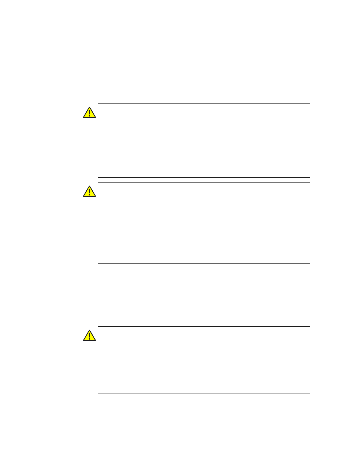
12.5 Dimensional drawings.................................................................................. 51
13 Ordering information........................................................................... 52
13.1 Scope of delivery...........................................................................................52
13.2 Ordering information ....................................................................................52
14 Accessories........................................................................................... 53
14.1 Ordering information, accessories...............................................................53
14.2 Weld spark guard..........................................................................................55
14.3 Deflector mirror.............................................................................................56
14.3.1 Mounting.......................................................................................57
14.3.2 Change in scanning range using deflector mirrors....................57
14.3.3 Deflector mirror PNS75 - ordering information..........................57
14.3.4 Deflector mirror PSN125 - ordering information....................... 58
14.4 Columns.........................................................................................................58
14.5 Test rods........................................................................................................59
15 List of figures........................................................................................ 60
4
O PE R AT I NG IN S TR U CT I ON S | deTec2 Core 8014276/2014-02-18 | SICK
Subject to change without notice
Page 5

CONTENTS
16 List of tables..........................................................................................61
17 Appendix................................................................................................62
17.1 Compliance with EC directives.....................................................................62
17.2 Checklist for initial commissioning and commissioning............................ 64
8014276/2014-02-18 | SICK
Subject to change without notice
O PE R AT I NG IN S TR U CT I ON S | deTec2 Core
5
Page 6

ABOUT THIS DOCUMENT
1
1 About this document
These operating instructions contain information required during the life cycle of the
safety light curtain.
These operating instructions are available to all those who work with the safety light
curtain.
Please read these operating instructions carefully and make sure that you understand
the content fully before working with the safety light curtain.
1.1 Scope
These operating instructions only apply to the deTec2 Core safety light curtain with the
following type label entry Operating Instructions: 8014274.
These operating instructions are included with SICK part number 8014274 (all availa‐
ble languages).
1.2 Target groups and structure of these operating instructions
These operating instructions are intended for the following target groups: project devel‐
opers (planners, developers, designers), installers, electricians, operators and mainte‐
nance personnel.
The structure of these operating instructions is based on the life cycle phases of the
safety light curtain: project planning, mounting, electrical installation, commissioning,
operation and maintenance.
In many applications, the audiences are assigned as follows to the manufacturer and
organization operating the machine, in which the safety light curtain is integrated:
Area of responsibility Target group Special chapters of these operating instruc‐
Manufacturer Project developers
(planners, developers,
designers)
Installers "Mounting", Page 24
Electricians "Electrical installation", Page 33
operating company Operator "Operation", Page 39
Maintenance person‐
nel
1)
Chapters not listed here are intended for all target groups. All target groups must take into account the
safety and warning instructions of the complete operating instructions!
1)
tions
"Project planning", Page 15
"Technical data", Page 47
"Accessories", Page 53
"Initial commissioning", Page 35
"Checklist for initial commissioning and com‐
missioning", Page 64
"Troubleshooting", Page 44
"Maintenance", Page 42
"Troubleshooting", Page 44
"Ordering information", Page 52
In other applications, the operating organization is also the manufacturer of the equip‐
ment with the corresponding allocation of the target groups.
6
O PE R AT I NG IN S TR U CT I ON S | deTec2 Core 8014276/2014-02-18 | SICK
Subject to change without notice
Page 7
1.3 Further information
www.sick.com The following information is available on the Internet:
– Other language versions
– Data sheets and application examples
– CAD data of drawings and dimensional drawings
– Certificates (e.g. EC declaration of conformity)
– Guidelines for safe machines (accident prevention with opto-electronic protective de‐
vices)
ABOUT THIS DOCUMENT 1
1.4
Symbols and document conventions
The following symbols are used in these operating instructions:
Instructions to actionbThe arrow denotes instructions to action. Read carefully and follow the instructions
for action.
LED symbols These symbols indicate the status of an LED:
The LED is off.
The LED is flashing.
The LED is illuminated continuously.
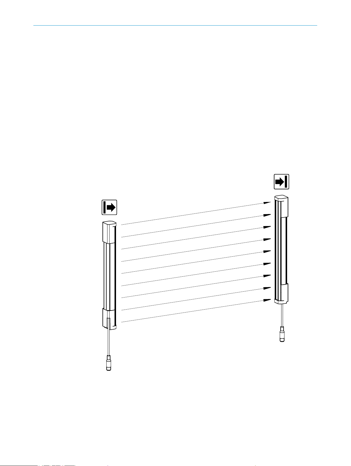
Sender and receiver These symbols indicate the sender and receiver of the safety light curtain:
The symbol indicates the sender.
The symbol indicates the receiver.
Warnings A warning indicates an actual or potential risk or dangers. It is designed to help you to
prevent accidents. Read carefully and follow the warnings!
The following warning types are used in these operating instructions:
CAUTION
Alerts you to a dangerous situation, which can result in a mild to moderate injury if not
avoided.
8014276/2014-02-18 | SICK
Subject to change without notice
WARNING
Alerts you to a dangerous situation, which can cause serious injury or death if not avoi‐
ded.
DANGER
Alerts you to a dangerous situation, which will cause serious injury or death if not avoi‐
ded.
NOTE
The "i" symbol denotes information and alerts you to possible damage and other impor‐
tant information.
O PE R AT I NG IN S TR U CT I ON S | deTec2 Core
7
Page 8

2 SAFETY INFORMATION
2 Safety information
This chapter contains information on general safety for the safety light curtain.
More safety information about specific usage situations of the safety light curtain is
available in the respective chapters.
2.1 General safety notes
DANGER
Risk of ineffectiveness of the protective device
Persons or parts of the body to be protected are not recognized in case of non-observ‐
ance.
Pay particular attention to all warnings in these operating instructions.
b
2.2 Correct use
The deTec2 Core safety light curtain is an electro-sensitive protective device (ESPE)
and is suitable for the following applications:
– Hazardous point protection
– Access protection
– Hazardous area protection
The deTec2 Core safety light curtain must be connected to the control such that the
machine cannot start while persons are present in the hazardous area. If a person can
stand behind the safety light curtain, there must be a restart interlock depending on
the applicable national regulations.
The deTec2 Core safety light curtain must be only used within the limits of the prescri‐
bed and specified technical data and operating conditions at all times.
The requirements defined in the technical specifications, e.g. power supply, cables and
ambient conditions, must be observed and maintained to allow the safety light curtain
to meet its warranted function.
If the product is used for any other purpose or modified in any way, any warranty claim
against SICK AG shall become void.
Foreseeable misuse Among others, the deTec2 Core safety light curtain is not suitable for the following ap‐
plications:
– Outdoors
– Under water
– In potentially explosive atmospheres
8
O PE R AT I NG IN S TR U CT I ON S | deTec2 Core 8014276/2014-02-18 | SICK
Subject to change without notice
Page 9
SAFETY INFORMATION 2
DANGER
Risk of ineffectiveness of the protective device
Persons and parts of the body to be protected are not recognized in case of non-ob‐
servance.
The width of the protective field must not change during operation of the safety light
b
curtain, see "Scanning range and protective field width", Page 16.
The components of the safety light curtain must not be tampered with, opened or
b
changed. Otherwise, any warranty claim against SICK AG shall become void.
Improper repair of the protective device can lead to a loss of the protective function.
b
The protective device must be repaired by the manufacture or by someone author‐
ized by the manufacturer.
DANGER
Risk of ineffectiveness of the protective device
Persons and parts of the body to be protected are not recognized in case of non-ob‐
servance.
The safety light curtain works as an indirect protective measure and cannot provide
protection from parts thrown out nor from emitted radiation. Transparent objects are
not detected.
Only use the safety light curtain as an indirect protective measure!
b
2.3
Requirements for the qualification of personnel
The safety light curtain must be configured, installed, connected, commissioned and
serviced only by qualified safety personnel.
Project planning For project planning, a person is considered competent when he/she has expertise and
experience in the selection and use of safety equipment on machines and is familiar
with the relevant technical rules and national work safety regulations.
Mechanical installation
and commissioning
For mechanical installation and commissioning, a person is considered competent
when he/she has the expertise and experience in the relevant field and is sufficiently
familiar with the application of the protective device on the machine that he/she can
assess its work safety aspects.
Electrical installation For electrical installation and commissioning, a person is considered competent when
he/she has the expertise and experience in the relevant field and is sufficiently familiar
with the application of the protective device on the machine that he/she can assess its
work safety aspects.
Operation and mainte‐
nance
For operation and maintenance, a person is considered competent when he/she has
the expertise and experience in the relevant field and is sufficiently familiar with the ap‐
plication of the protective device on the machine and has been instructed by the ma‐
chine operator in its operation.
8014276/2014-02-18 | SICK
Subject to change without notice
An operator must clean and check the safety light curtain.
Additional information for the operator of the machine: see "Operation", Page 39 and
"Regular cleaning", Page 42.
O PE R AT I NG IN S TR U CT I ON S | deTec2 Core
9
Page 10
3 PRODUCT DESCRIPTION
3 Product description
This chapter provides information on the operation of the safety light curtain and shows
examples of its range of use.
3.1 Structure and function
The deTec2 Core safety light curtain is an electro-sensitive protective device (ESPE)
consisting of a sender and receiver.
A series of parallel infrared light beams form a protective field between sender and re‐
ceiver that protects the hazardous area (hazardous point, access and hazardous area
protection). When one or more beams are completely interrupted, the safety light cur‐
tain reports the interruption in the light path to the secure output signal switching devi‐
ces (OSSDs) by a signal change. The signal to stop the dangerous state of the machine
must be evaluated by a safe control or safety relay (contactors).
Sender and receiver automatically synchronize themselves optically. An electrical con‐
nection between both components is not required.
Figure 1: Sender and receiver
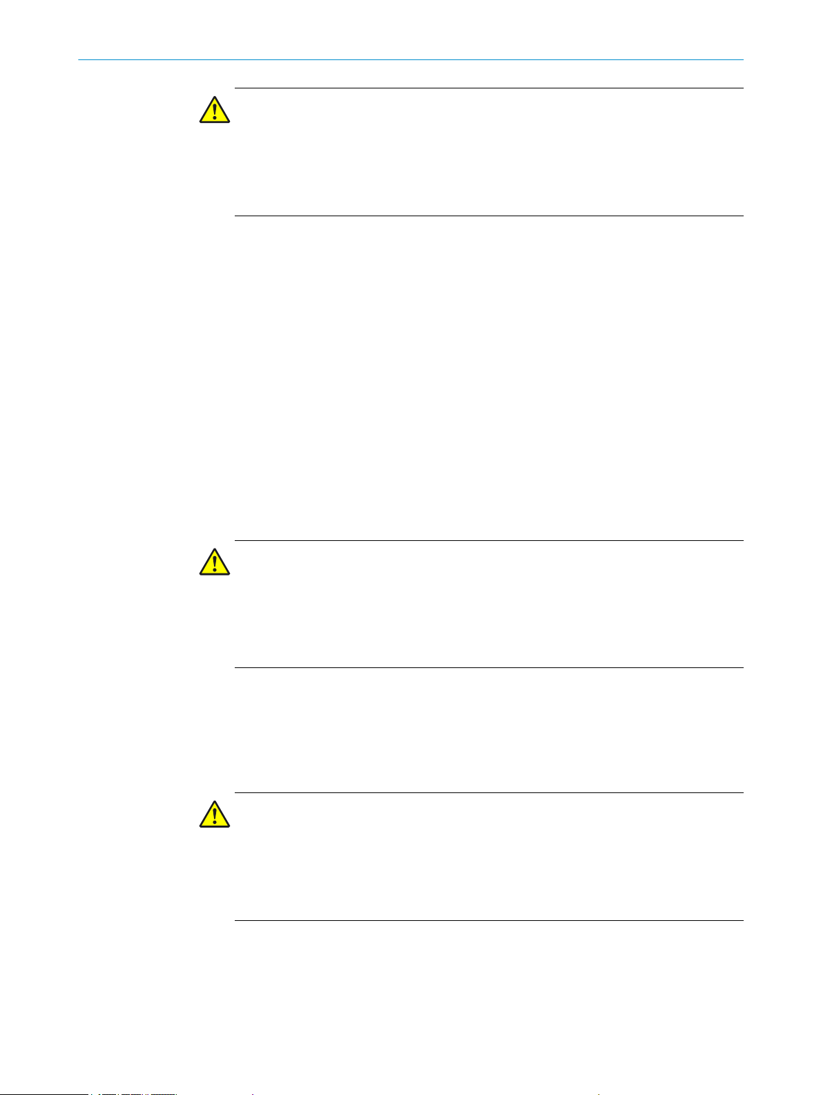
Protective field height The protective field height indicates the range within which the test rod belonging to
the safety light curtain is detected. The size of the safety light curtain determines the
protective field height. The design and construction of the safety light curtain deTec2
Core extends the protective function of a device to the end of the housing without any
blind spots.
10
O PE R AT I NG IN S TR U CT I ON S | deTec2 Core 8014276/2014-02-18 | SICK
Subject to change without notice
Page 11
Resolution 30 mmResolution 14 mm
ERR
PWR
ERR
PWR
PRODUCT DESCRIPTION
Protective field range Die Schutzfeldbreite ist die Länge des Lichtweges zwischen Sender und Empfänger. Sie
ist durch die Reichweite begrenzt. Informationen zu Schutzfeldhöhe, Auflösung und
Schutzfeldbreite: see "Data sheet", Page 47.
Resolution With the appropriate resolution, the safety light curtain provides finger and hand pro‐
tection. The resolution corresponds to the diameter of the test rod belonging to the
safety light curtain, which is reliably detected when in the protective field.
3
Interrelationship: Reso‐
lution and scanning
range
The deTec2 Core safety light curtain is available with a protective field height of 300
mm to 2100 mm (150 mm steps). The available resolution versions are 14 mm (0 - 7
m scanning range) and 30 mm (0 - 10 m scanning range).
The scanning range is reduced by using deflector mirrors and/or a weld spark guard.
Additional information: see "Deflector mirror", Page 56 and "Weld spark guard",
Page 55.
3.2 Product characteristics
3.2.1 Absence of blind zones
The design and construction of the safety light curtain extends the protective function
of a device to the end of the housing without any blind spots. The absence of blind
zones reduces the space requirement when integrated in the machine.
3.2.2 Automatic calibration of the protective field width
When switched on, the safety light curtain automatically calibrates to the protective
field width.
3.2.3 Status indicators
The sender and receiver LEDs indicate the operating status of the safety light curtains.
Status indicators of the
sender
8014276/2014-02-18 | SICK
Subject to change without notice
Figure 2: Sender indicators
The sender has two LEDs, which indicate the operating status:
O PE R AT I NG IN S TR U CT I ON S | deTec2 Core
11
Page 12
Resolution 30 mmResolution 14 mm
ERR
OSSD
ERR
OSSD
1 2 3 4
1 2 3 4
2
1
3
PRODUCT DESCRIPTION
3
Status indicators of the
receiver
Item LED color Display Labeling
1 Yellow Status indicator PWR
2 Red Fault indicator ERR
For a complete overview of the fault indications: see "Fault indicators", Page 44.
Figure 3: Receiver indicators
The receiver has six LEDs, which indicate the operating status:
Item LED color Display Labeling
1 Red/green OSSD status indicator OSSD
2 Red Fault indicator ERR
3 Blue Alignment quality 1, 2, 3, 4
Blue LEDs in combination with the red flashing ERR LED also denote fault indications.
For a complete overview of the fault indications: see "Fault indicators", Page 44.
12
O PE R AT I NG IN S TR U CT I ON S | deTec2 Core 8014276/2014-02-18 | SICK
Subject to change without notice
Page 13
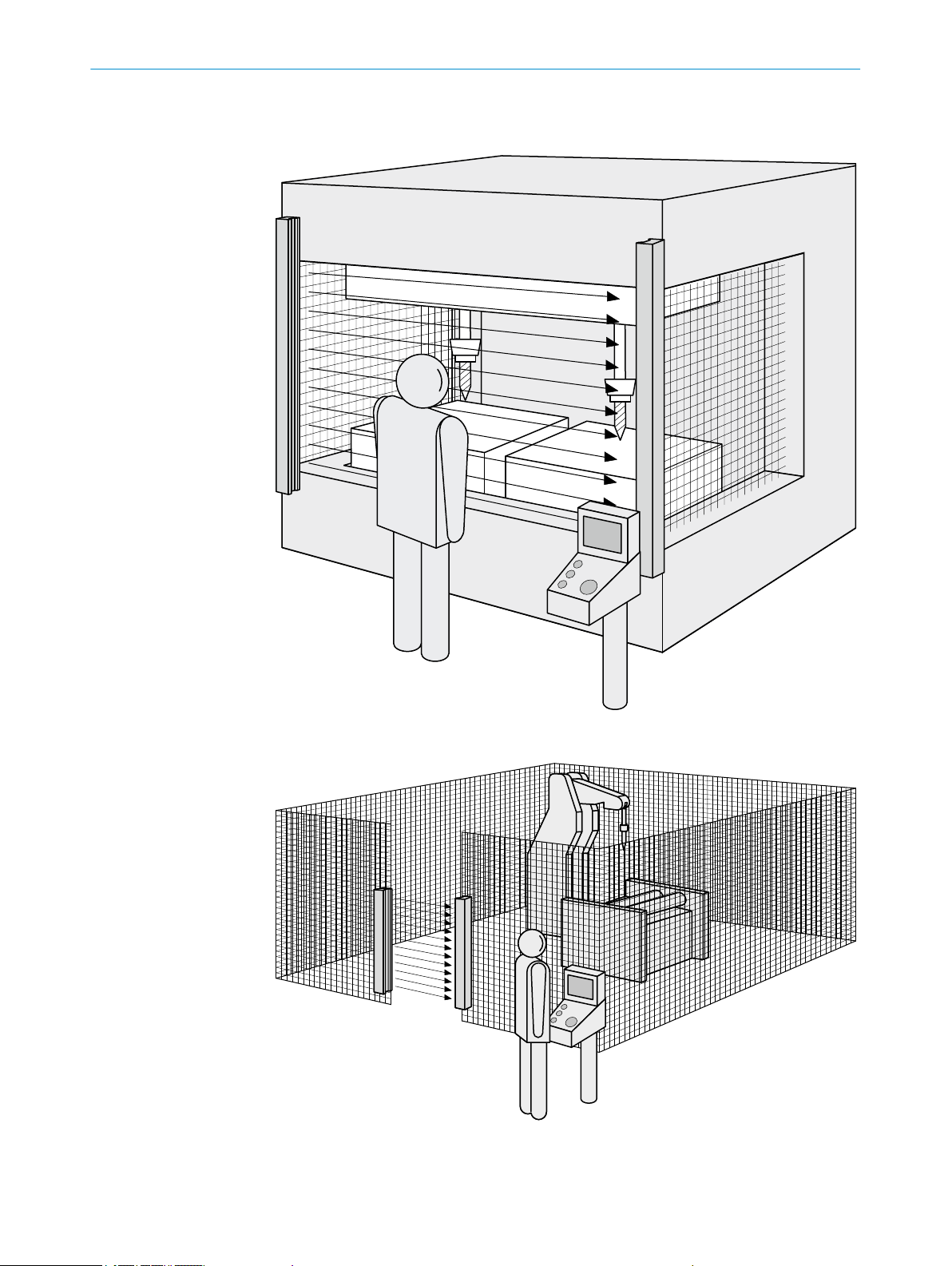
3.3 Example applications
PRODUCT DESCRIPTION
3
Figure 4: Hazardous point protection
Figure 5: Access protection
8014276/2014-02-18 | SICK
Subject to change without notice
O PE R AT I NG IN S TR U CT I ON S | deTec2 Core
13
Page 14
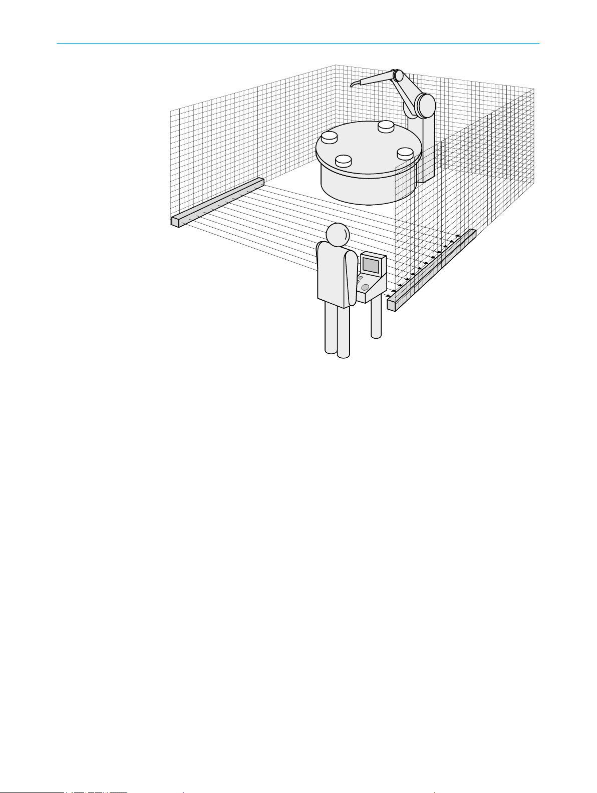
PRODUCT DESCRIPTION
3
Figure 6: Hazardous area protection
14
O PE R AT I NG IN S TR U CT I ON S | deTec2 Core 8014276/2014-02-18 | SICK
Subject to change without notice
Page 15

4 Project planning
This chapter includes important information about the proper integration of the safety
light curtain in machines for planners, developers and designers.
4.1 Manufacturer of the machine
DANGER
Risk of ineffectiveness of the protective device
Persons and parts of the body to be protected are not recognized in case of non-ob‐
servance.
Use of the safety light curtain requires a risk analysis. Check whether additional pro‐
b
tective measures are required.
Comply with the applicable national regulations derived from the application (e.g.
b
work safety regulations, safety rules or other relevant safety guidelines).
Do not combine the components of the safety light curtain with components from
b
other safety light curtains.
The components of the safety light curtain must not be tampered with, opened or
b
changed. Otherwise, any warranty claim against SICK AG shall become void.
Improper repair of the protective device can lead to a loss of the protective function.
b
The protective device must be repaired by the manufacture or by someone author‐
ized by the manufacturer.
PROJECT PLANNING 4
4.2 Operator of the machine
DANGER
Risk of ineffectiveness of the protective device
Persons and parts of the body to be protected are not recognized in case of non-ob‐
servance.
Changes to the electrical integration of the safety light curtain in the machine control
b
and changes to the mechanical installation of the safety light curtain require another
risk analysis.
The results of the risk analysis may require the operator of the machine to meet the
b
obligations of a manufacturer.
The components of the safety light curtain must not be tampered with, opened or
b
changed. Otherwise, any warranty claim against SICK AG shall become void.
Improper repair of the protective device can lead to a loss of the protective function.
b
The protective device must be repaired by the manufacture or by someone author‐
ized by the manufacturer.
4.3 Design
This chapter contains important information about the design.
Information about the individual steps for installation of the device: see "Mounting",
Page 24.
8014276/2014-02-18 | SICK
Subject to change without notice
O PE R AT I NG IN S TR U CT I ON S | deTec2 Core
15
Page 16
4 PROJECT PLANNING
DANGER
Risk of ineffectiveness of the protective device
Persons and parts of the body to be protected are not recognized in case of non-ob‐
servance.
Make sure that the following design requirements are met such that the safety light
b
curtain can fulfill its protective function.
– Sender and receiver must be arranged such that persons or parts of the body are
reliably detected when they enter the hazardous area.
– Reaching under, over and around as well as moving the safety light curtain must be
prevented.
– If people can stop between the protective device and the hazardous point without
being detected, check if additional protective measures (e. g. restart interlock with a
reset button) are required.
4.3.1 Scanning range and protective field width
Scanning range The scanning range limits the maximum protective field width. The protective field
width cannot change during operation see "Technical data", Page 47.
The scanning range, see "Deflector mirror", Page 56 and "Weld spark guard",
Page 55 is reduced by using deflector mirrors and/or a weld spark guard.
Protective field range The protective field range is the dimension of the light path between sender and receiv‐
er. It is automatically calibrated with switching on the safety light curtain during initiali‐
zation and must not be changed during operation.
DANGER
Risk of ineffectiveness of the protective device
Persons and parts of the body to be protected are not recognized in case of non-ob‐
servance.
The safety light curtain can only be mounted to machines on which the protective
b
field width does not change when the safety light curtain is switched on.
4.3.2 Minimum distance from the hazardous point
A minimum distance must be maintained between the safety light curtain and the haz‐
ardous point. This distance is required to prevent a person or part of the body from
reaching the hazardous area before the dangerous state of the machine state has com‐
pleted.
DANGER
Risk of ineffectiveness of the protective device
The dangerous state of the machine is not stopped or not stopped in a timely manner
for non-compliance.
Calculate minimum dis‐
tance
16
O PE R AT I NG IN S TR U CT I ON S | deTec2 Core 8014276/2014-02-18 | SICK
Calculate the required minimum distance for your machine.
b
Mount the safety light curtain taking this calculation into account.
b
The calculation of the minimum distance is based on international and national stand‐
ards and statutory requirements applicable at the place of installation of the machine.
If the minimum distance is calculated according to ISO 13855, then it depends on the
following points:
Subject to change without notice
Page 17
PROJECT PLANNING
– Machine stopping time (time interval between triggering the sensor function and the
end of the dangerous state of the machine)
– Response time of the protective device see "Response time", Page 49
– Reach or approach speed of the person
– Resolution (detection capability) of the safety light curtain
– Type of approach: orthogonal or parallel
– Parameters specified based on the application
For the USA (scope of OSHA and ANSI), the following regulations apply among others:
a) Laws: Code of Federal Regulations, Title 29 (CFR29) Part 1910.217
b) Standards: ANSI B11.19
NOTE
Additional information is available in the ISO 13855 standard and in the Guidelines
Safe Machinery.
NOTE
SICK offers to measure the stopping/run-down time as a service in many countries.
4
8014276/2014-02-18 | SICK
Subject to change without notice
Figure 7: Minimum distance to hazardous point for orthogonal approach to protective field
Calculation example of the minimum distance S according to ISO 13855
The example shows the calculation of the minimum distance for orthogonal approach
to the protective field. Depending on the application and the ambient conditions (e.g. a
protective field parallel or at an arbitrary angle to the direction of approach or an indi‐
rect approach), a different calculation may be required.
– First, calculate S using the following formula:
S = 2000 × T + 8 × (d – 14) [mm]
where
O PE R AT I NG IN S TR U CT I ON S | deTec2 Core
17
Page 18
4 PROJECT PLANNING
– T = machine stopping time + response time of the protective device after interrup‐
tion in the light path [s]
– d = resolution of the safety light curtain [mm]
– S = minimum distance [mm]
The reach/approach speed is already included in the formula.
– If the result S ≤ is 500 mm, then use the determined value as the minimum dis‐
tance.
– If the result S is > 500 mm, then recalculate S as follows:
S = 1600 × T + 8 × (d – 14) [mm]
– If the new value S is > 500 mm, then use the newly determined value as the mini‐
mum distance.
– If the new value S is ≤ 500 mm, then use 500 mm as the minimum distance.
Example calculation Machine stopping time = 290 ms
Response time after interruption of the light path = 30 ms
Resolution of the safety light curtain = 14 mm
T = 290 ms + 30 ms = 320 ms = 0.32 s
S = 2000 × 0.32 + 8 × (14 – 14) = 640 mm
S > 500 mm, therefore:
S = 1600 × 0,32 + 8 × (14 – 14) = 512 mm
Taking reaching over in‐
to account
If access to the hazardous area cannot be ruled out by reaching over a vertical protec‐
tive field, the height of the protective field and minimum distance of the ESPE must be
determined. This is done by comparing the calculated values based on the possible de‐
tection of limbs or body parts with the values resulting from reaching over the protec‐
tive field. The greater value resulting from this comparison must be used. This compari‐
son is to be carried out according to ISO 13855, Section 6.5 or national regulations.
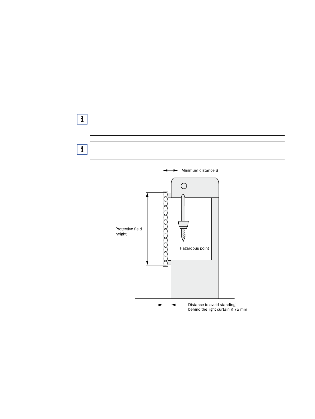
Figure 8: Representation of the accessibility of ESPE by reaching over. Left: Protective field that
cannot be reached over. Right: Protective field that can be reached over.
4.3.3 Minimum distance to reflective surfaces
18
DANGER
Risk of ineffectiveness of the protective device
Reflective surfaces and dispersive media can prevent persons or parts of the body to
be protected from being properly reflected and therefore, remain undetected.
Make sure that all reflective surfaces and objects maintain a minimum distance
b
from the protective field.
Make sure that no dispersive media is found within the calculated minimum dis‐
b
tance from the protective field.
O PE R AT I NG IN S TR U CT I ON S | deTec2 Core 8014276/2014-02-18 | SICK
Subject to change without notice
Page 19
D
a
a [mm]
1100
1000
900
800
700
600
500
400
300
200
100
0,5 1 1,5 2 2,5 3 3,5 4 4,5 5 5,5 6 6,5 7 7,5 8 8,5 9 9,5 10 11 12 D [m]
PROJECT PLANNING 4
The light beams from the sender may be deflected by reflective surfaces and dispersive
media. This can result in non-detection of an object.
Therefore, all reflective surfaces and objects (e.g. material bins, machine table, etc.)
must maintain a minimum distance (a) from the protective field. This minimum dis‐
tance (a) must be maintained on all sides of the protective field. This applies in horizon‐
tal, vertical and diagonal directions as well as at the end of the safety light curtain.
Make sure that no dispersive media is found within the calculated minimum distance
from the protective field.
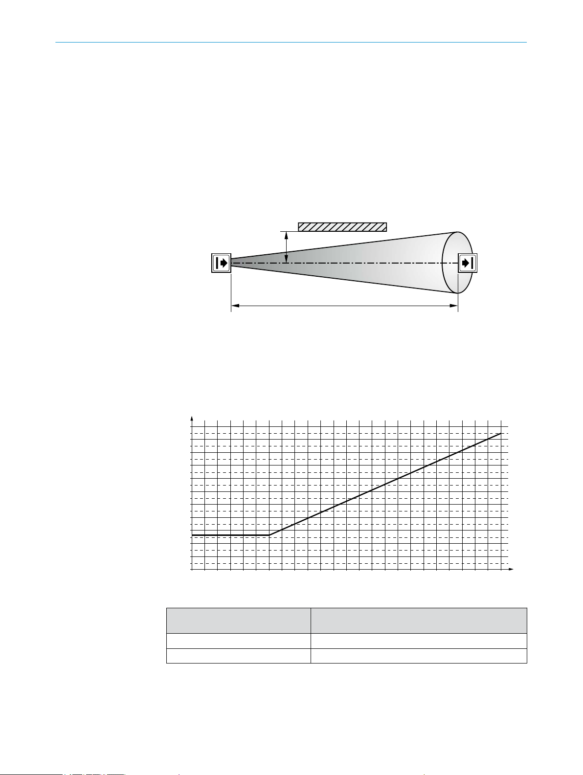
The minimum distance (a) depends on the distance (D) between sender and receiver
(protective field width).
Figure 9: Minimum distance to reflective surfaces
How to determine the minimum distance from reflective surfaces:
Determine the distance D [m], sender – receiver.
b
Read the minimum distance a [mm] in the graph or calculate it based on the respec‐
b
tive formula from Tab. 1:
Figure 10: Graph, minimum distance from reflective surfaces
8014276/2014-02-18 | SICK
Subject to change without notice
Distance (D) [m]
Sender–receiver
D ≤ 3 m a [mm] = 262
D > 3 m a [mm] = tan (5°) × 1000 × D [m] = 87,49 × D [m]
Table 1: Formula for calculating the minimum distance from reflective surfaces
Calculation of the minimum distance (a) from reflective
surfaces
O PE R AT I NG IN S TR U CT I ON S | deTec2 Core
19
Page 20
System 1
System 2
PROJECT PLANNING
4
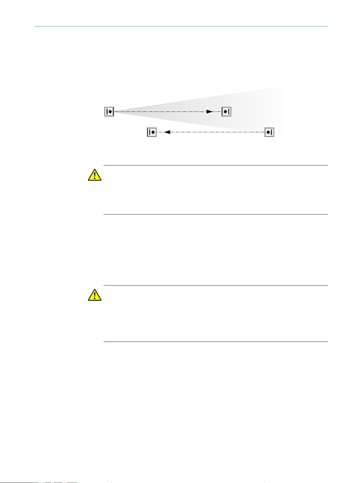
4.3.4 Protection against interference from systems in close proximity to each other
The infrared light beams of the sender of system 1 can interfere with the receiver of
system 2. This can disrupt the protective function of system 2. This would mean that
the operator is at risk. Avoid such installation situations or take appropriate action, e.g.
install optically opaque partitions or reverse the direction of transmission of a system.
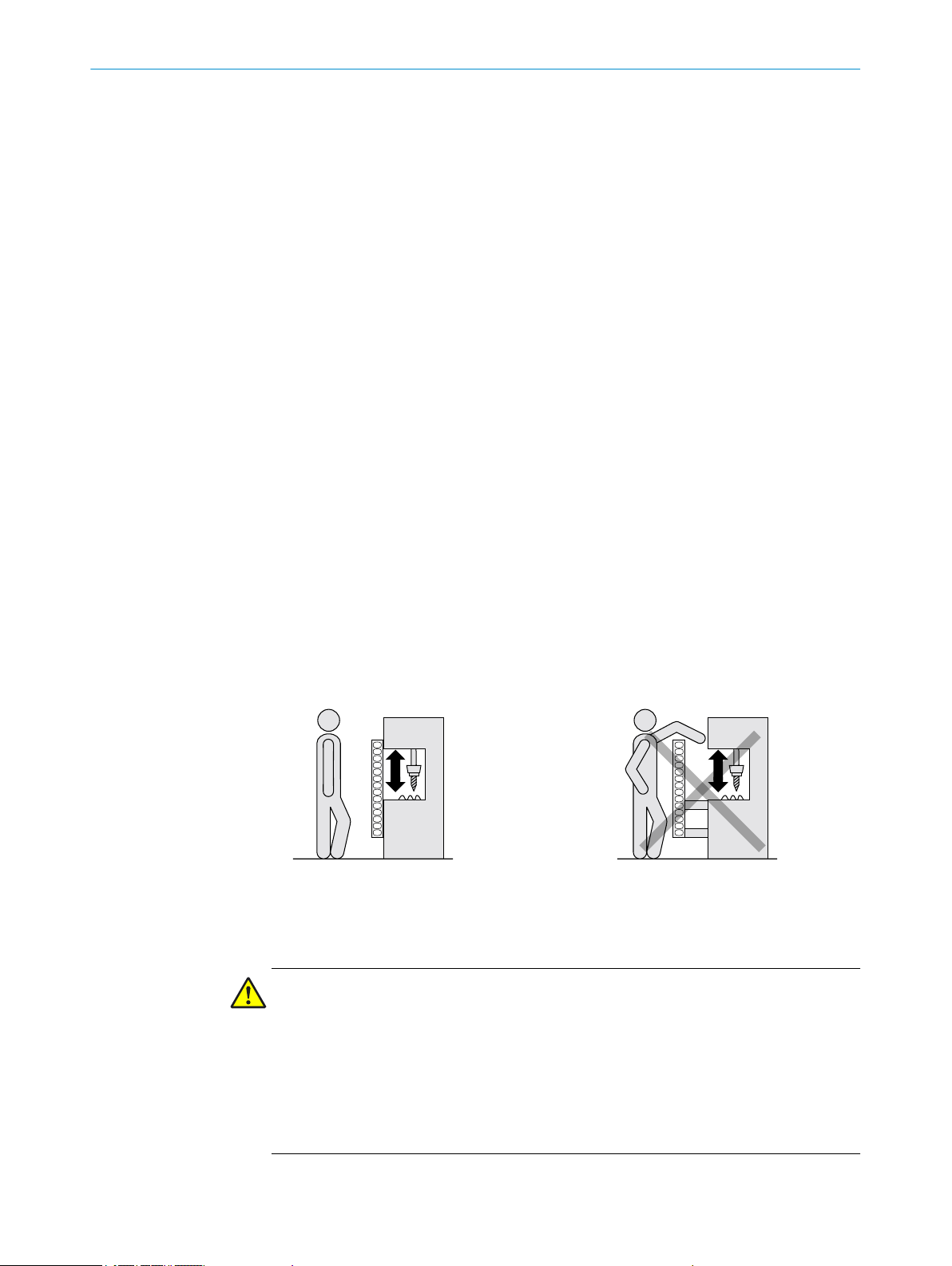
Figure 11: The direction of transmission of systems in close proximity to each other is reversed.
The sender of the 2nd system is not affected by the beams 1st system.
DANGER
Risk of ineffectiveness of the protective device
Several systems of safety light curtains in close proximity to each other can interfere
with each other.
Prevent interference from systems in close proximity to each other.
b
4.4 Integration in electrical control
This chapter contains important information about integration in the electrical control.
Information about the individual steps for electrical installation of the device: see "Elec‐
trical installation", Page 33.
Requirements for use Depending on the safety concept, the signal to stop the dangerous state of the ma‐
chine must be evaluated by a safe control or safety relay (external control).
DANGER
Risk of ineffectiveness of the protective device
Persons and parts of the body to be protected are not recognized in case of non-ob‐
servance.
Make sure that the following control and electrical requirements are met such that
b
the safety light curtain can fulfill its protective function.
– The control of the machine must allow electrical interference.
– The electrical control of the machine must meet the requirements of IEC 60204-1.
– A restart interlock must be implemented depending on applicable national regula‐
tions or required reliability of the safety function. Because the safety light curtain
does not have this function, it must be implemented in the external control if re‐
quired.
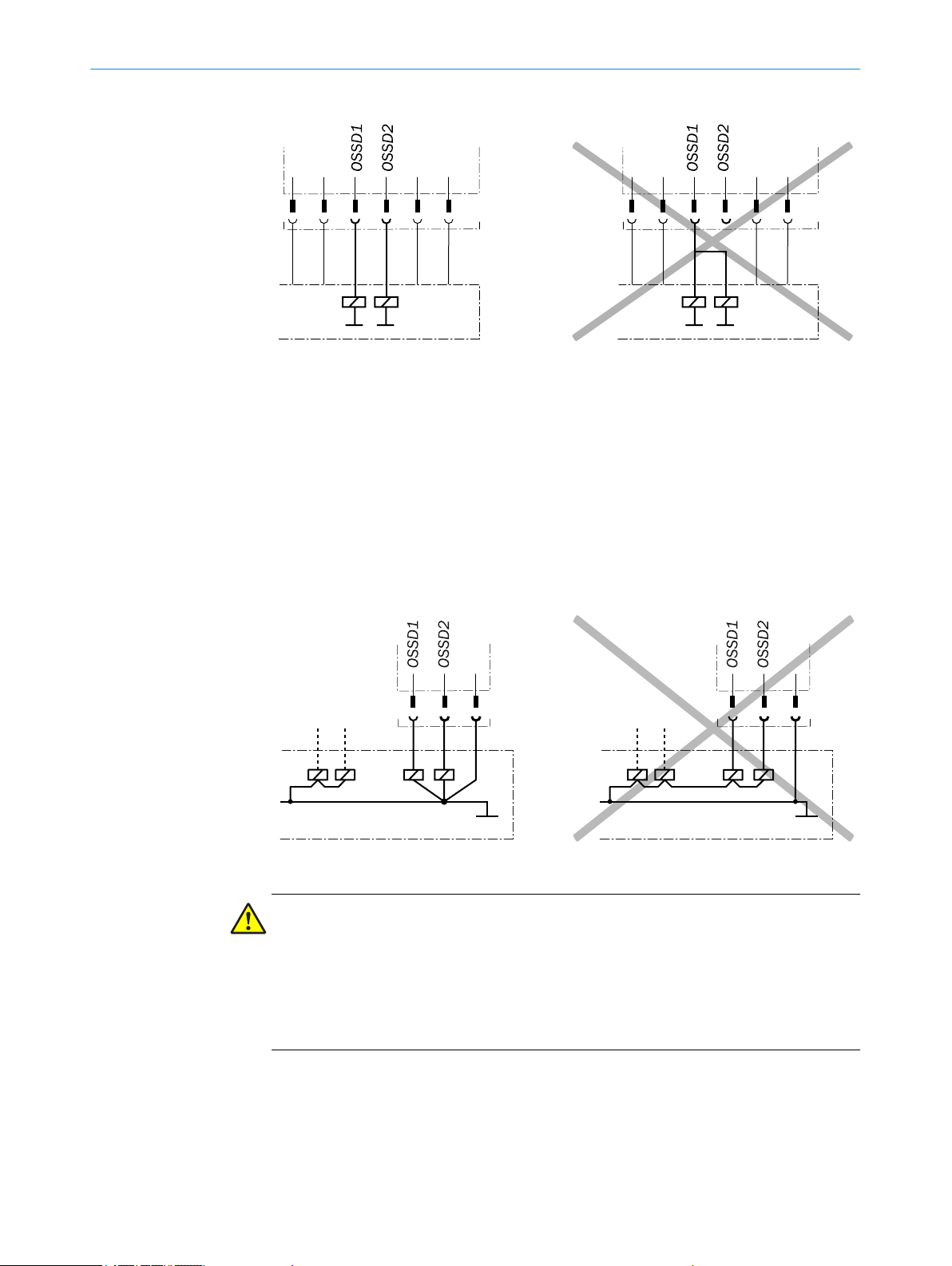
– When using a safe control, different signal levels of both OSSDs must be detected
depending on applicable national regulations or required reliability of the safety
function. The maximum time tolerated by the control during which the OSSDs may
exhibit different states must be selected according to the application.
– The OSSD1 and OSSD2 output signals must not be connected to each other.
– In the machine controller, the signals of both OSSDs must be processed separately.
20
O PE R AT I NG IN S TR U CT I ON S | deTec2 Core 8014276/2014-02-18 | SICK
Subject to change without notice
Page 21
PROJECT PLANNING
Figure 12: Dual-channel and isolated connection of OSSD1 and OSSD2
– The machine must switch to the safe state at any time if at least one of the two
OSSDs switches to the LOW state.
– Prevent the formation of a potential difference between the load and the protective
device. If you connect loads to the OSSDs (safety outputs) that then also switch if
controlled with negative voltage (e.g. electro-mechanical contactor without reverse
polarity protection diode), you must connect the 0 V connections of these loads and
those of the corresponding protective device individually and directly to the same 0
V terminal strip. In the event of a fault, this is the only way to ensure that there can
be no potential difference between the 0 V connections of the loads and those of the
corresponding protective device.
4
8014276/2014-02-18 | SICK
Subject to change without notice
Figure 13: No potential difference between load and protective device
DANGER
Risk of ineffectiveness of the protective device
Persons and parts of the body to be protected are not recognized in case of non-ob‐
servance.
Contactors connected in series must be positively guided and monitored.
Make sure that contactors connected in series are monitored!
b
– When using external switching elements (e.g. positively guided contactors), verifica‐
tion of the external switching elements (external device monitoring) must be imple‐
mented depending on applicable national regulations or required reliability of the
safety function. Because the safety light curtain does not have this function, it must
be implemented in the external control if required.
O PE R AT I NG IN S TR U CT I ON S | deTec2 Core
21
Page 22

4 PROJECT PLANNING
Requirements for the
electrical control of the
machine
The two outputs are protected against short-circuits to 24 V DC and 0 V. When the pro‐
tective field is clear, the signal level on the outputs is HIGH (at potential) and when the
light beams are interrupted or there is a device fault the outputs are LOW (over 1.5 kΩ
towards 0 V).
The safety light curtain complies with the rules for electromagnetic compatibility (EMC)
for the industrial sector (Radio Safety Class A). Radio interference cannot be ruled out
when used in residential areas.
DANGER
Risk of ineffectiveness of the protective device
Persons and parts of the body to be protected are not recognized in case of non-ob‐
servance.
Make sure that the following requirements for electrical control of the machine are
b
met such that the safety light curtain can fulfill its protective function.
– The external power supply of the safety light curtain must be capable of buffering
brief power failures of 20 ms as specified in EN 60204-1.
– The power supply unit must provide safe isolation according to IEC 61140
(SELV/PELV). Suitable power supplies are available as accessories from SICK, see
"Ordering information, accessories", Page 53.
4.4.1 Restart interlock and external device monitoring
A restart interlock and/or verification of the external switching elements (external de‐
vice monitoring) must be implemented depending on applicable national regulations or
required reliability of the safety function.
Restart interlock A restart interlock prevents the machine from starting again as long as the operator
does not explicitly reset it. The dangerous state of the machine (1) is stopped if the
light path is interrupted (2) and is not re-enabled (3) until the operator presses the re‐
set device (4).
Figure 14: Schematic representation of operation with restart interlock
The restart interlock should not be confused with the start interlock of the machine.
The start interlock prevents the machine from starting after switching on. The restart
interlock prevents the machine from starting again after a fault or an interruption in the
protective field.
22
There must be a restart interlock depending on the applicable national regulations
when a person can stand behind the safety light curtain. The safety light curtain does
not have an internal restart interlock. Therefore, a restart interlock must be implemen‐
ted externally via the circuitry or the control, e.g. in connection with the SICK switching
amplifier UE48-2OS/UE48-3OS.
O PE R AT I NG IN S TR U CT I ON S | deTec2 Core 8014276/2014-02-18 | SICK
Subject to change without notice
Page 23

S34 S21S35 S22
S33 S12S11 S31
14A2 24 32
13A1 23 31
UE48-2OS2D2
K1 K2
S1
K1
K2
OSSD1
OSSD2
n.c.
GND
+24V
1
2
3
4
5
+24V
n.c.
GND
n.c.
n.c.
1
2
3
4
5
24 VDC
0 VDC
PROJECT PLANNING
4
External device monitor‐
ing (EDM)
Connection diagram for
UE48-2OS with restart
interlock and external
device monitoring
The external device monitoring checks if the contactors used to end the dangerous
state of the machine de-energize (switch off) when the protective device responds.
NOTE
Because the safety light curtain does not have external device monitoring, it must be
implemented in the external control.
Figure 15: Connection diagram for UE48-2OS with restart interlock and external device monitor‐
ing
The safety light curtain can be connected to the UE48-2OS switching amplifiers. It is
operated with restart interlock and external device monitoring.
Functionality
When the protective field is clear, the OSSD1 and OSSD2 outputs carry voltage. The
system can be switched on when K1 and K2 are in the de-energized position. Pressing
the S1 button switches on the UE48 switching amplifier. Contacts 13-14 and 23-24 of
the UE48 activate the K1 and K2 contactors.
When the protective field is interrupted, the OSSD1 and OSSD2 outputs carry no volt‐
age. The UE48 switches off and K1, K2 are deactivated.
Fault analysis
Failure of K1 and K2 does not cause the loss of the shut-down function. Cross-circuits
and short-circuits of the OSSD1 and OSSD2 outputs are recognized and lead to the
locking state. It is recognized if the K1 or K2 contactors does not de-energize.
8014276/2014-02-18 | SICK
Subject to change without notice
O PE R AT I NG IN S TR U CT I ON S | deTec2 Core
23
Page 24

5 MOUNTING
5 Mounting
5.1 Safety
This chapter describes how to mount the safety light curtain using the included Quick‐
Fix bracket.
A FlexFix bracket is also available with extended adjustment possibilities, see "Accesso‐
ries", Page 53.
The following steps are necessary after mounting and installation:
– "Electrical installation", Page 33
– "Align the sender and receiver", Page 36
– "Initial commissioning", Page 35
NOTE
Mount the safety light curtain in the following order.
Information about the requirements for properly mounting the safety light curtain see
"Design", Page 15.
5.2 Unpacking
5.3 Installation
DANGER
Dangerous state of the machine
Make sure that the dangerous state of the machine is (and remains) switched off.
b
Make sure that the outputs of the safety light curtain have no effect on the machine.
b
DANGER
Risk of ineffectiveness of the protective device
Persons or parts of the body to be protected are not recognized in case of non-observ‐
ance.
Only use brackets recommended by SICK for mounting.
b
Take appropriate measures for vibration dampening if the vibration and shock re‐
b
quirements are above the values and test conditions specified in the data sheet, see
"Data sheet", Page 47.
Check the components for completeness and the integrity of all parts, see "Scope of
b
delivery", Page 52.
Please contact your respective SICK subsidiary should you have any complaints.
b
24
The QuickFix bracket or the optional FlexFix bracket is used to mount the sender and
receiver. In many cases, the QuickFix bracket is enough for installation. The FlexFix
bracket makes it possible to rotate sender and receiver around the axis of the device
and to align it accurately.
O PE R AT I NG IN S TR U CT I ON S | deTec2 Core 8014276/2014-02-18 | SICK
Subject to change without notice
Page 25

DANGER
Risk of ineffectiveness of the protective device
Persons or parts of the body to be protected are not recognized or not recognized in
time in case of non-observance.
It is vital that you observe the minimum distance calculate for your machine: see
b
"Minimum distance from the hazardous point", Page 16 and see "Minimum distance
to reflective surfaces", Page 18
Mount the safety light curtain such that the hazardous point cannot be reached from
b
below, above or behind the safety light curtain and that the light curtain cannot be
repositioned.
NOTE
Read this section completely before mounting the brackets.
b
Read the section "Align the sender and receiver", Page 36
b
Mounting instructionsbMount the sender and receiver on a level surface.
Mount the sender and receiver at the same height. For minor adjustments when
b
aligning, the sender and receiver can be adjusted vertically in the brackets, see
"Fig. 27: QuickFix bracket: adjust vertically", Page 36 and see "Fig. 28: FlexFix
bracket: adjust vertically / rotate", Page 37.
When possible, mount the top bracket at a height such that the offset in the housing
b
of the safety light curtain sites on the bracket to prevent the safety light curtain from
sliding down.
The end with the cable connection must point in the same direction for both devices.
b
MOUNTING
5
8014276/2014-02-18 | SICK
Subject to change without notice
Figure 16: Sender and receiver must not be installed at 180° rotated relative to each other.
O PE R AT I NG IN S TR U CT I ON S | deTec2 Core
25
Page 26

5 MOUNTING
Tighten the screws used to mount the bracket at a torque of 5 - 6 Nm. Tighten the
b
screws used to secure the safety light curtain in the bracket at a torque of 2.5 - 3
Nm. Higher torques can damage the bracket while lower torques do not provide ade‐
quate fixation to prevent the safety light curtain from moving in the event of vibra‐
tions.
When mounting, make sure that sender and receiver are aligned correctly. The opti‐
b
cal lens systems of sender and receiver must be located in opposition to each other.
If necessary, use a water level to check the parallelism of the components.
b
5.3.1 Mount the QuickFix bracket
QuickFix brackets can be mounted in two ways:
– On the side
– On the back
The two mounting surfaces for the brackets of the sender or receiver must not be an‐
gled more than 0.5° to each other. If not possible, use the optional FlexFix bracket.
Mount QuickFix bracket
on the side of a ma‐
chine or profile frame
Two QuickFix brackets are used to mount the sender and receiver.
The QuickFix bracket consists of two parts, which are pushed into each other. An M5
screw is used to join both parts and to clamp the housing (sender or receiver).
Mounting can be carried out in two ways:
With the M5 screw through the QuickFix bracket to the machine or profile frame. A
b
screw nut or threaded hole is required on the machine or profile frame.
With the M5 screw through the machine or profile frame to the QuickFix bracket. A
b
screw nut is required for each QuickFix bracket.
When choosing the length of the M5 screw (hexagon head or cylinder head screw),
b
consider the QuickFix bracket and the machine or profile frame.
CAUTION
Risk of injury from protruding screws thread
When mounting through the machine or profile frame to the QuickFix bracket, the M5
screw can present an injury risk if too long.
Select an appropriate screw length to prevent any risk of injury from an overrun.
b
26
O PE R AT I NG IN S TR U CT I ON S | deTec2 Core 8014276/2014-02-18 | SICK
Subject to change without notice
Page 27

Figure 17: Mount QuickFix bracket to a profile
MOUNTING 5
NOTE
The QuickFix bracket has cable routing. Depending on the installation, the cable routing
can make mounting easier.
5.3.2 Mount optional FlexFix bracket
In the FlexFix bracket, sender and receiver can be flexibly rotated by +/− 15°. FlexFix
brackets can be mounted in two ways:
– On the side
– On the back
NOTE
Use flat head screws for rear-side mounting of FlexFix holders so that the safety light
curtain housing cannot be scratched by any protruding screw heads.
Mount FlexFix bracket
on the side of a ma‐
chine or profile frame
Two FlexFix brackets are used to mount the sender and receiver at the designated
points.
The M5 screws are used to mount through the FlexFix bracket to the machine or profile
frame. A screw nut or threaded hole is required on the machine or profile frame.
8014276/2014-02-18 | SICK
Subject to change without notice
O PE R AT I NG IN S TR U CT I ON S | deTec2 Core
27
Page 28
5 MOUNTING
Figure 18: Mount FlexFix bracket to a profile frame
After mounting the FlexFix brackets, screw the sender or receiver into the FlexFix
b
brackets from the front and align the sender and receiver, see "Align the sender and
receiver", Page 36.
NOTE
The safety light curtain can only be screwed in when both FlexFix brackets are in align‐
ment. A water level can be used to help. If necessary, use a water level to check the
parallelism of the components.
28
O PE R AT I NG IN S TR U CT I ON S | deTec2 Core 8014276/2014-02-18 | SICK
Subject to change without notice
Page 29

MOUNTING 5
Mount FlexFix bracket
to the back of a device
column
8014276/2014-02-18 | SICK
Subject to change without notice
Figure 19: Inserting the safety light curtain in the FlexFix brackets
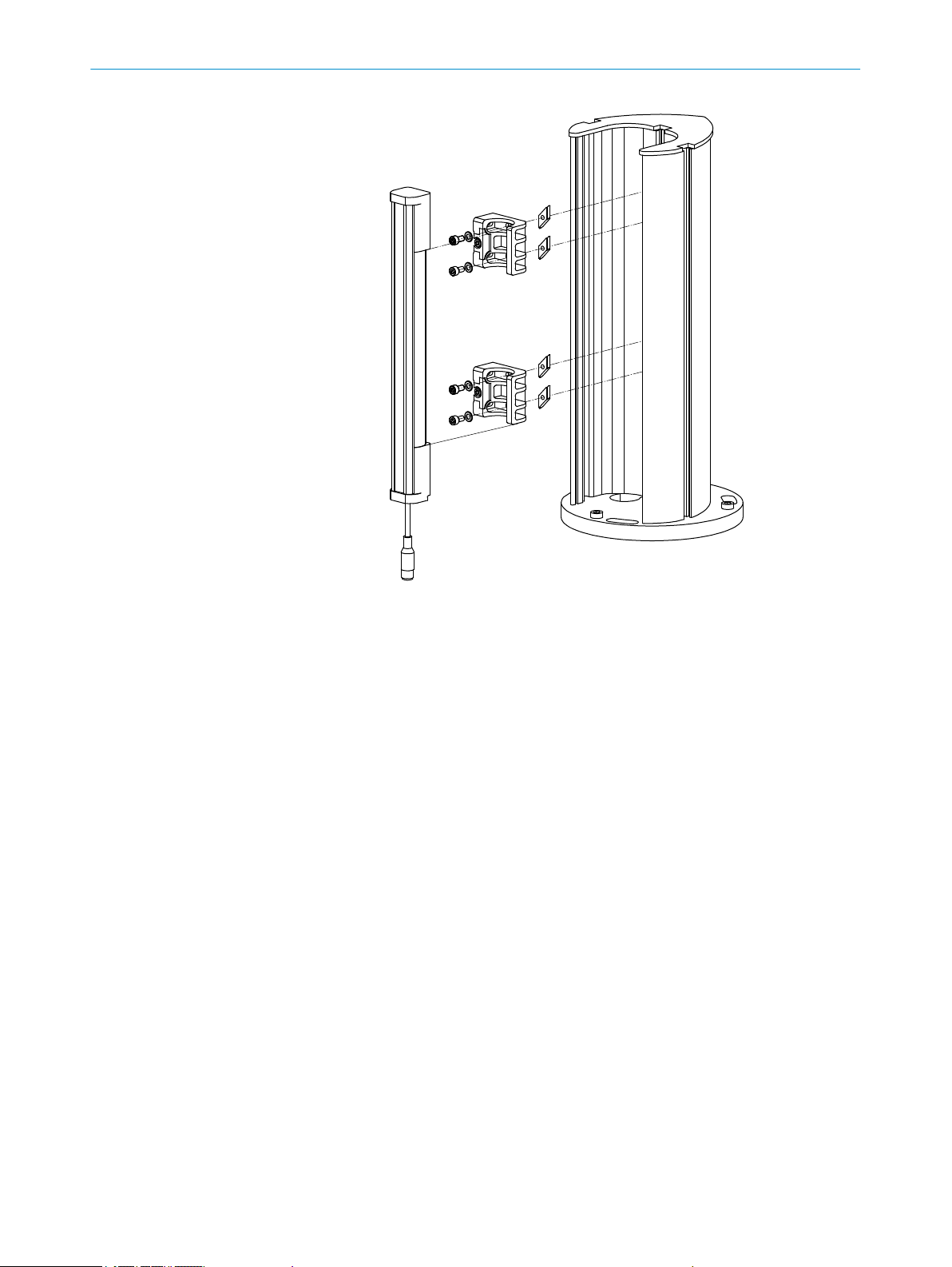
Use an M5 screw to fix the position of the sender and receiver in the FlexFix bracket.
b
Two FlexFix brackets are used to mount the sender and receiver. Two M5 screws are
required to mount a FlexFix bracket. A FlexFix bracket can be mounted to a device col‐
umn with two sliding nuts in the groove of the device column.
NOTE
The BEF-1SHABBKU2 mounting kit contains two FlexFix brackets and the required
screws and sliding nuts, see "Ordering information, accessories", Page 53.
After mounting the FlexFix brackets, screw the sender or receiver into the FlexFix
b
brackets from the front and align the sender and receiver, see "Align the sender and
receiver", Page 36.
Use an M5 screw to fix the position of the sender and receiver in the FlexFix bracket.
b
O PE R AT I NG IN S TR U CT I ON S | deTec2 Core
29
Page 30
5 MOUNTING
Figure 20: Mount FlexFix bracket to a device column (accessory)
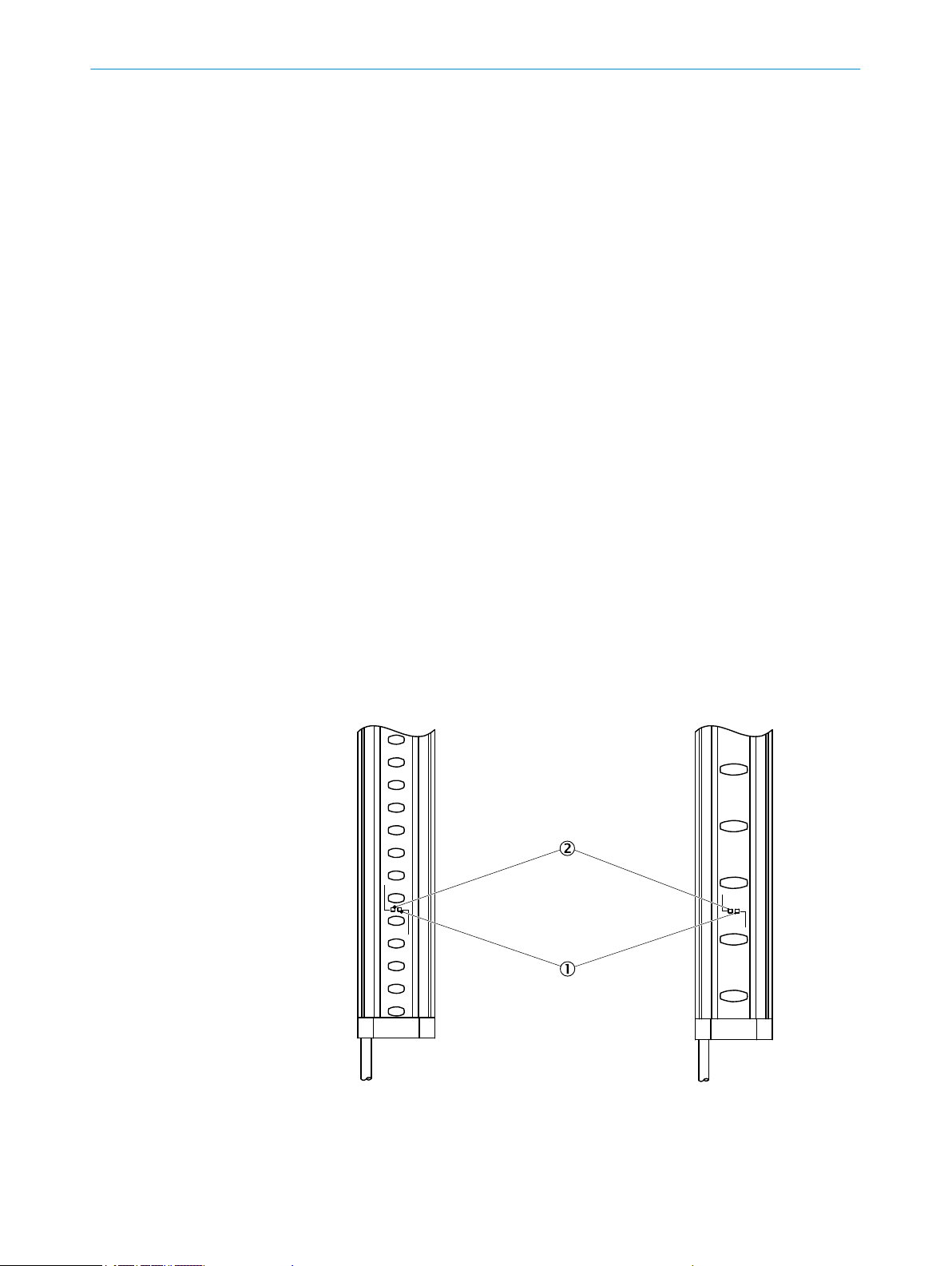
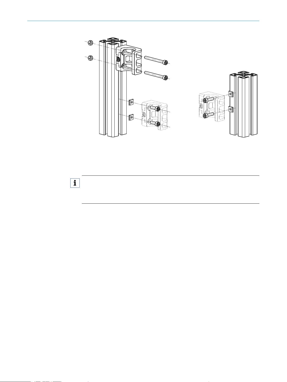
5.3.3 Mount optional replacement bracket
If an existing C2000 safety light curtain is mounted with a swivel-mount bracket or with
a side bracket, it can be replaced with a deTec2 Core safety light curtain using a re‐
placement bracket. There is no need to drill new holes, since the existing ones can be
used for the replacement bracket.
Use one of the following installation versions independent of the existing situation
b
that prevails:
To replace a swivel mount bracket (article number 2019649 or 2019659): installa‐
•
tion version A or B
To replace a side bracket (article number 2019506): installation version C
•
30
O PE R AT I NG IN S TR U CT I ON S | deTec2 Core 8014276/2014-02-18 | SICK
Subject to change without notice
Page 31

MOUNTING 5
Figure 21: Replacement bracket, installation version A
Figure 22: Replacement bracket, installation version B
8014276/2014-02-18 | SICK
Subject to change without notice
O PE R AT I NG IN S TR U CT I ON S | deTec2 Core
31
Page 32

5 MOUNTING
5.4
Figure 23: Replacement bracket, installation version C
Attach information label
Use the "Important Information" label in the language of the operator of the ma‐
b
chine. Use several information labels if additional languages are required for other
operators.
Affix "Important Information" label to the machine in close proximity to sender and
b
receiver. The information label is self-adhesive.
Affix the information label such that it is easily visible by each operator during opera‐
b
tion. After attaching additional objects and equipment, the information label must
not be concealed from view.
32
O PE R AT I NG IN S TR U CT I ON S | deTec2 Core 8014276/2014-02-18 | SICK
Subject to change without notice
Page 33

6 Electrical installation
This chapter describes the electrical installation of the safety light curtain.
6.1 Safety
Information about the requirements that must be met for safe integration of the safety
light curtain in the control and electronics of the machine: see "Integration in electrical
control", Page 20.
Mounting should be completed before electrical installation.
DANGER
Risk of electric shock
Risk of the machine starting unexpectedly
Make sure that the machine is (and remains) disconnected from the power supply
b
during the electrical installation.
Make sure that the dangerous state of the machine is (and remains) switched off.
b
Only use an appropriate power supply, see "Technical data", Page 47.
b
Make sure that the outputs of the safety light curtain have no effect on the machine
b
during the electrical installation.
ELECTRICAL INSTALLATION 6
DANGER
Risk of ineffectiveness of the protective device
Connect OSSD1 and OSSD2 separately. OSSD1 and OSSD2 must not be connected
b
to each other. Otherwise, signal safety will not be ensured.
Figure 24: Connection of OSSD1 and OSSD2
DANGER
Risk of ineffectiveness of the protective device
8014276/2014-02-18 | SICK
Subject to change without notice
Prevent the formation of a potential difference between the load and the protective
b
device.
O PE R AT I NG IN S TR U CT I ON S | deTec2 Core
33
Page 34

6 ELECTRICAL INSTALLATION
If you connect loads to the OSSDs (safety outputs) that then also switch if controlled
b
with negative voltage (e.g. electro-mechanical contactor without reverse polarity pro‐
tection diode), you must connect the 0 V connections of these loads and those of the
corresponding protective device individually and directly to the same 0 V terminal
strip. In the event of a fault, this is the only way to ensure that there can be no po‐
tential difference between the 0 V connections of the loads and those of the corre‐
sponding protective device.
Figure 25: No potential difference between load and protective device
6.2 Device connection (M12, 5-pin)
Figure 26: Sender and receiver
Pin Wire color Sender Receiver
1 brown 24 V DC input (power sup‐
2 White Reserved OSSD1 (output signal
3 Blue 0 V DC input (power sup‐
4 black Reserved OSSD2 (output signal
5 gray Not yet assigned Not yet assigned
Table 2: Device connection pin assignment (M12, 5-pin)
Connection diagram for the electrical installation: see "Integration in electrical control",
Page 20.
ply)
ply)
24 V DC input VDC24 (pow‐
er supply)
switching device 1)
0 V DC input (power sup‐
ply)
switching device 2)
6.3 Device connection via connection cable (M12, 5-pin to 8-pin)
An optional connection cable is available to connect the 5-pin device connection to an
existing 8-pin socket. The connection cable can be used to replace an existing C2000
safety light curtain with a deTec2 Core, without having to route new cables.
34
O PE R AT I NG IN S TR U CT I ON S | deTec2 Core 8014276/2014-02-18 | SICK
Subject to change without notice
Page 35

7 Initial commissioning
The mounting and electrical installation must be completed before initial commission‐
ing as described in the following chapters.
– "Design", Page 15
– "Integration in electrical control", Page 20
– "Mounting", Page 24
– "Electrical installation", Page 33
7.1 Safety
DANGER
Risk of ineffectiveness of the protective device
When changes are made to machines, the effectiveness of the protective device may
be affected unintentionally.
After every change to the machine and changes to the integration and/or operation‐
b
al and secondary conditions of the safety light curtain, check the protective device
for effectiveness and recommission as specified in this chapter.
INITIAL COMMISSIONING 7
DANGER
Dangerous state of the machine
b
DANGER
Risk of ineffectiveness of the protective device
b
b
b
b
b
7.2 Switching on
After switching on, initialize the sender and receiver. All LEDs of the sender and receiv‐
er briefly light up. After initialization, the receiver displays the alignment quality using
four blue LEDs. The alignment indicator goes out after a certain time after the safety
light curtain is aligned (OSSD LED: green) and only the PWR LED of the sender and
OSSD LED of the receiver illuminate.
Make sure that the dangerous state of the machine is (and remains) switched off.
Before you operate a machine protected by the safety light curtain for the first time,
make sure that the machine is first checked and released by qualified safety person‐
nel.
Make sure that the optical properties of the front screen of the sender and receiver
are not changed by beading water, mist, frost or ice formation.
Make sure that all reflective surfaces and objects maintain a minimum distance
from the protective field.
Make sure that no dispersive media is found within the calculated minimum dis‐
tance from the protective field.
Only operate the machine when the protective function of the safety light curtain is
operating properly.
8014276/2014-02-18 | SICK
Subject to change without notice
In the event of a fault, the red fault LED flashes on the respective device. The red fault
LED in combination with the blue LEDs show the cause of the fault on the side of the
receiver, see "Troubleshooting", Page 44.
O PE R AT I NG IN S TR U CT I ON S | deTec2 Core
35
Page 36

*) Exception for protective field height 300 mm
H
≤ L/4*
L
≤ L/4
7 INITIAL COMMISSIONING
7.3 Align the sender and receiver
After mounting and the electrical installation, the sender and receiver must be aligned
with each other.
DANGER
Dangerous state of the machine
Make sure that the outputs of the safety light curtain have no effect on the machine
b
during the alignment process.
Alignment with the
QuickFix bracket
You have the following adjustment options with the QuickFix bracket:
– Adjust vertically (H)
Figure 27: QuickFix bracket: adjust vertically
NOTE
If the alignment cannot be adjusted with the QuickFix bracket, use the optional FlexFix
bracket.
36
O PE R AT I NG IN S TR U CT I ON S | deTec2 Core 8014276/2014-02-18 | SICK
Subject to change without notice
Page 37

*) Exception for protective field height 300 mm
H
≤ L/4*
L
≤ L/4
+/–15°
INITIAL COMMISSIONING
7
Indication of the align‐
ment quality
Aligning with the FlexFix
bracket or with the re‐
placement bracket
Display Meaning
Blue LEDs OSSD LED
No LED lights up Red Alignment is insufficient or the protective field is inter‐
rupted at least partially. The receiver cannot synchronize
with the sender.
1 LED lights up Red Alignment is insufficient or the protective field is inter‐
rupted at least partially.
2 LEDs light up Red Alignment is poor or the protective field is interrupted at
least partially.
2 LEDs light up Green Alignment is not yet sufficient for stable availability.
3 LEDs light up Green Alignment is good, stable availability.
1)
4 LEDs light up Green Alignment is very good.
Table 3: Blue LEDs to indicate the alignment quality
1)
At a typical scanning range, there is a possibility that all four LEDs to indicate alignment quality do not
light up even when alignment is good.
NOTE
Once the system is aligned, at least two blue LEDs light up and the OSSD LED is green.
You have the following adjustment options with the FlexFix bracket or the replacement
bracket:
– Adjust vertically (H)
– Rotate (+/− 15 °)
Figure 28: FlexFix bracket: adjust vertically / rotate
8014276/2014-02-18 | SICK
Subject to change without notice
O PE R AT I NG IN S TR U CT I ON S | deTec2 Core
37
Page 38

7 INITIAL COMMISSIONING
Align the sender and re‐
ceiver to each other
How to align sender and receiver with FlexFix bracket or with the replacement bracket:
Switch on the power supply to the safety light curtain.
b
Pay attention to the mounting heights of sender and receiver.
b
Provide a rectangular protective field.
b
Roughly align the sender to the receiver by rotating the sender.
b
Roughly align the receiver to the sender by rotating the receiver.
b
Look for the four blue LEDs of the receiver. The LEDs signal the alignment quality.
b
Adjust the sender and receiver such that as many blue LEDs illuminate as possible.
If the receiver switches to "Green", secure the components in the brackets at a tor‐
b
que of 2.5 - 3 Nm.
Switch off the power supply and on again.
b
Check the blue LEDs to make sure that the components are still correctly aligned
b
with each other.
NOTE
Once three blue LEDs illuminate, alignment is good and availability is stable.
NOTE
The optional laser alignment aid AR60 can be used for alignment, see "Ordering infor‐
mation, accessories", Page 53.
Since the laser alignment assistant is placed in the protective field of the safety light
curtain with the adapter, the indicator for the alignment quality shows a maximum of
two blue LEDs and the OSSD LED is red. To check whether the OSSD LED of the receiv‐
er is illuminating green, remove the laser alignment assistant.
7.4 Checks
Checks before initial
commissioning/
commissioning
The purpose of the checks described in the following is to confirm the safety require‐
ments specified in the national/international rules and regulations, especially the safe‐
ty requirements in the Machine (EU Conformity) or Work Equipment Directive.
These checks are also used to check the effectiveness of the protective device.
These checks must therefore always be performed.
The checks must be carried out by qualified safety personnel or specially qualified
b
and authorized personnel and must be recorded and documented to ensure that the
tests can be reconstructed and retraced at any time.
Check the effectiveness of the protective device for all operating modes selectable
b
on the machine "Checklist for initial commissioning and commissioning", Page 64
in the appendix.
Make sure that the operating personnel have been instructed in the function of the
b
protective device before being allowed to operate the machine. Instructing the oper‐
ating personnel is the responsibility of the organization operating the machine and
must be conducted by qualified personnel.
Please note the test notes for the operator in chapter "Daily check", Page 39.
b
38
O PE R AT I NG IN S TR U CT I ON S | deTec2 Core 8014276/2014-02-18 | SICK
Subject to change without notice
Page 39
8 Operation
8.1 Safety
OPERATION 8
This chapter describes the operation of the safety light curtain that primarily consists of
checking the effectiveness of the protective device on a daily basis.
These operating instructions do not provide information on operating the machine in
which the safety light curtain is integrated.
DANGER
Risk of ineffectiveness of the protective device after changes
Persons and parts of the body to be protected are not recognized in case of non-ob‐
servance.
Maintenance work, alignment work, fault diagnoses and any changes to the integra‐
b
tion of the safety light curtain in the machine must only be carried out by qualified
personnel.
Then check the effectiveness of the protective device and recommission as speci‐
b
fied in chapter "Initial commissioning", Page 35.
8.2 Daily check
Checking the effective‐
ness with the test rod
DANGER
Risk of ineffectiveness of the protective device
Persons and parts of the body to be protected are not recognized in case of non-ob‐
servance.
Make sure that the optical properties of the front screen of the sender and receiver
b
are not changed by beading water, mist, frost or ice formation.
Make sure that all reflective surfaces and objects maintain a minimum distance
b
from the protective field, see "Minimum distance to reflective surfaces", Page 18.
Make sure that no dispersive media is found within the calculated minimum dis‐
b
tance from the protective field.
The effectiveness of the protective device must be checked daily using the included
test rod. The diameter of the test rod corresponds to the resolution of the light curtain.
Before introducing the test rod, check if the OSSD LED illuminates green. If not, then
you must first change this state. The check is otherwise meaningless.
DANGER
Risk of ineffectiveness of the protective device
Persons and parts of the body to be protected are not recognized in case of non-ob‐
servance.
8014276/2014-02-18 | SICK
Subject to change without notice
Only use the included test rod with the diameter specified on the type label of the
b
safety light curtain.
Do not use any test rods with a similar or the same diameter of other safety light
b
curtains.
O PE R AT I NG IN S TR U CT I ON S | deTec2 Core
39
Page 40

OPERATION
8
DANGER
Risk of the machine starting unexpectedly
Make sure that the dangerous state of the machine is (and remains) switched off
b
during the check.
Make sure that the outputs of the safety light curtain have no effect on the machine
b
while checking the components.
Move the test rod slowly through the protective field to be tested as indicated by the
b
arrow in Fig. 29.
Watch the OSSD LED on the receiver during the check. The OSSD LED on the receiv‐
er should continuously light up red. The OSSD LED may not light up green.
Figure 29: Daily checks of the protective device: Step 1
Guide the test rod along the edges of the protective field as indicated by the arrow in
b
Fig. 30.
Watch the OSSD LED on the receiver during the check. The OSSD LED on the receiv‐
er should continuously light up red. The OSSD LED may not light up green.
40
O PE R AT I NG IN S TR U CT I ON S | deTec2 Core 8014276/2014-02-18 | SICK
Subject to change without notice
Page 41

Figure 30: Daily checks of the protective device: Step 2
OPERATION 8
If you use one or more deflector mirrors (see "Accessories", Page 53), then also
b
guide the test rod slowly through the protective field directly in front of the deflector
mirrors.
Watch the OSSD LED on the receiver during the check. The OSSD LED on the receiv‐
er should continuously light up red. The OSSD LED may not light up green.
DANGER
Risk of ineffectiveness of the protective device
Persons and parts of the body to be protected are not recognized in case of non-ob‐
servance.
Do not operate the machine if the OSSD LED lights up green during the test!
If the OSSD LED lights up green during the test even if only briefly, work must stop at
b
the machine.
In this case, the mounting and electrical installation of the safety light curtain must
b
be checked by qualified safety personnel, see "Mounting", Page 24, "Electrical instal‐
lation", Page 33.
8014276/2014-02-18 | SICK
Subject to change without notice
O PE R AT I NG IN S TR U CT I ON S | deTec2 Core
41
Page 42

9 MAINTENANCE
9 Maintenance
The safety light curtain is maintenance-free. Depending on the ambient conditions, reg‐
ular cleaning is required.
9.1 Safety
DANGER
Risk of ineffectiveness of the protective device
Persons and parts of the body to be protected are not recognized in case of non-ob‐
servance.
Do not conduct any repairs on the device components (sender, receiver).
b
Do not open the device components.
b
9.2 Regular cleaning
DANGER
Risk of ineffectiveness of the protective device
Persons and parts of the body to be protected are not recognized in case of non-ob‐
servance.
Regularly check the degree of contamination on all components based on the appli‐
b
cation conditions.
Please observe the chapter "Daily check", Page 39.
b
Depending on the ambient conditions of the safety light curtain, the front screens must
be cleaned regularly and in the event of contamination. Static charges can cause dust
particles to be attracted to the front screen. The weld spark guard and deflector mirror
must be cleaned regularly and in the event of contamination.
DANGER
Risk of ineffectiveness of the protective device
Persons and parts of the body to be protected are not recognized in case of non-ob‐
servance.
Make sure that the optical properties of the front screens of the sender and receiver
b
are not changed by:
– beading water, mist, frost or ice formation. If necessary, remove any residues of
this type or any other form of contamination and restart the receiver.
– Scratches or damage. If necessary, replace the respective sender or receiver if its
front screen is scratched or damaged.
Make sure that all reflective surfaces and objects maintain a minimum distance
b
from the protective field.
Make sure that no dispersive media is found within the calculated minimum dis‐
b
tance from the protective field.
42
O PE R AT I NG IN S TR U CT I ON S | deTec2 Core 8014276/2014-02-18 | SICK
Subject to change without notice
Page 43

MAINTENANCE 9
DANGER
Risk of the machine starting unexpectedly
Make sure that the dangerous state of the machine is (and remains) switched off
b
while cleaning.
While cleaning, the outputs of the safety light curtain are not allowed to have any
b
effect on the machine.
NOTE
Do not use aggressive cleaning agents.
b
Do not use abrasive cleaning agents.
b
We recommend anti-static cleaning agents.
b
We recommend the use of anti-static plastic cleaner (SICK part number 5600006)
b
and the SICK lens cloth (SICK part number 4003353).
How to clean the front screen
Use a clean, soft brush to remove dust from the front screen.
b
Then wipe the front screen with a clean, damp cloth.
b
Check the position of sender and receiver after cleaning.
b
Check the effectiveness of the protective device. Information on the testing proce‐
b
dure, see "Daily check", Page 39.
9.3 Regular inspection
DANGER
Risk of ineffectiveness of the protective device
Persons and parts of the body to be protected are not recognized in case of non-ob‐
servance.
The checks must be carried out by qualified safety personnel or specially qualified
b
and authorized personnel and must be recorded and documented to ensure that the
tests can be reconstructed and retraced at any time.
Check the machine following the inspection intervals specified in the national rules
b
and regulations. This procedure ensures that any changes to the machine or manip‐
ulations of the protective device are detected after initial commissioning.
Check the machine again according to the checklist in the appendix, see "Checklist
b
for initial commissioning and commissioning", Page 64:
– If changes are made to the machine or protective devices (e.g. changes to the
mechanical, electrical, optical connection)
– If sender or receiver have been replaced
Safety signs, informa‐
tion labels
Regularly check the information labels for the following points:
b
– Presence
– Readability
Replace the information labels if missing, damaged or illegible.
b
Please observe the chapter "Attach information label", Page 32.
b
8014276/2014-02-18 | SICK
Subject to change without notice
O PE R AT I NG IN S TR U CT I ON S | deTec2 Core
43
Page 44

10 TROUBLESHOOTING
10 Troubleshooting
This chapter describes how you identify and remedy faults that interrupt the function of
the safety light curtain.
10.1 Safety
DANGER
Risk of ineffectiveness of the protective device
Persons and parts of the body to be protected are not recognized in case of non-ob‐
servance.
Immediately put the machine out of operation if the behavior of the machine cannot
b
be clearly identified.
Immediately put the machine out of operation if you cannot clearly identify or allo‐
b
cate the fault and if you cannot safely remedy the fault.
Secure the machine such that it cannot be switched on unintentionally.
b
DANGER
Risk of the machine starting unexpectedly
Secure the machine such that it cannot be switched on unintentionally.
b
NOTE
If you cannot remedy a fault with the help of the information provided in this chapter,
please contact your respective SICK subsidiary.
10.2 Fault indicators
In the event of a fault, the type of fault is indicated by the LED display on the sender or
receiver.
Sender
PWR LED (yel‐
low)
Table 4: Fault indicator on the sender
ERR LED (red) Possible cause Rectification
No operating voltage or op‐
erating voltage is too low or
internal fault
The voltage was too high
when operating the sender.
Check the power supply,
see "Technical data",
Page 47.
Switch off the power supply
and on again.
If the fault persists, replace
the sender, see "Ordering
information", Page 52.
Check the power supply,
see "Technical data",
Page 47.
Replace the sender, see
"Ordering information",
Page 52.
44
O PE R AT I NG IN S TR U CT I ON S | deTec2 Core 8014276/2014-02-18 | SICK
Subject to change without notice
Page 45

TROUBLESHOOTING 10
Receiver
PWR LED (yel‐
ERR LED (red) Possible cause Rectification
low)
Table 4: Fault indicator on the sender
OSSD
LED
(red)
ERR
LED
(red)
LED 1 2 3 4
(blue)
Table 5: Fault indicator on the receiver
Fault in the supply voltage Check the voltage supply
and power supply, see
"Technical data",
Page 47.
Switch off the power supply
and on again.
If the fault persists, replace
the defective components,
see "Ordering information",
Page 52.
The sender identified an in‐
ternal fault.
Switch off the power supply
and on again.
If the fault persists, replace
the sender, see "Ordering
information", Page 52.
Possible cause Rectification
An internal fault has occur‐
red.
Switch off the power supply
and on again. If the fault
persists, replace the receiv‐
er, see "Ordering informa‐
tion", Page 52.
Fault in the supply voltage Check the voltage supply
and power supply, see
"Technical data",
Page 47.
Switch off the power supply
and on again.
If the fault persists, replace
the defective components,
see "Ordering information",
Page 52.
The receiver has recog‐
nized beams from several
senders.
Check the distance to
senders of the same type.
Make sure that beams
from another sender can‐
not hit the receiver, see
"Protection against interfer‐
ence from systems in close
proximity to each other",
Page 20. Switch off the
power supply and on again.
A fault or unexpected state
was identified on the
OSSDs of the system con‐
nection (e. g. over voltage,
short-circuit to HIGH or
short-circuit to LOW, crosscircuit, permissible load ca‐
pacity exceeded)
Check the system wiring for
a fault. Make sure that the
OSSDs have been wired
correctly, see "Integration
in electrical control",
Page 20. Switch off the
power supply and on again.
If the fault persists, replace
the defective components,
see "Ordering information",
Page 52.
8014276/2014-02-18 | SICK
Subject to change without notice
O PE R AT I NG IN S TR U CT I ON S | deTec2 Core
45
Page 46

11 DECOMMISSIONING
11 Decommissioning
11.1 Protection of the environment
The safety light curtain has been designed to minimize its impact on the environment.
It uses only minimum of power and natural resources.
At work, always act in an environmentally responsible manner. For this reason,
b
please note the following information on disposal.
11.2 Disposal
Always dispose of serviceableness devices in compliance with local/national rules and
regulations with respect to waste disposal.
NOTE
We would be pleased to be of assistance on the disposal of this device. Contact us.
46
O PE R AT I NG IN S TR U CT I ON S | deTec2 Core 8014276/2014-02-18 | SICK
Subject to change without notice
Page 47

12 Technical data
12.1 Data sheet
TECHNICAL DATA 12
General system data
Minimum Typical Maximum
Protective field height, depending on
300 mm to 2100 mm, 150 mm steps
type
Resolution (detection capability), de‐
14 mm or 30 mm
pending on the type
Protective field range
Resolution 14 mm
Resolution 30 mm
Protection class (EN 50178)
1)
0 ... 7 m
0 ... 10 m
2)
III
0 ... 8 m
0 ... 12 m
Enclosure rating (EN 60529) IP 65
IP 67
Supply voltage V
on the device 3)
Residual ripple
s
4)
5)
19.2 V 24 V 28.8 V
±10%
Synchronization Optical
Model name (EN 61496-1) Type 2
Category (EN ISO 13849-1) Category 2
Performance level
6)
PL c
(EN ISO 13849-1)
Safety Integrity Level
SIL claim limit
PFHd (mean probability of a danger‐
6)
6)
SIL1 (IEC 61508)
SILCL1 (EN 62061)
3.1 × 10
-8
ous failure per hour)
TM (Mission Time) 20 years (EN ISO 13849-1)
Safe state when a fault occurs At least one OSSD is in the LOW state
Power-up delay of sender and receiv‐
2 s
er before ready
Table 6: General system data
1)
At a typical scanning range, there is a possibility that all four LEDs to indicate alignment quality do not
light up even when alignment is good.
2)
Safety extra-low voltage SELV/PELV
3)
The external voltage supply must be capable of buffering brief power failures of 20 ms as specified in
EN 60204-1. Suitable power supplies are available as accessories from SICK.
4)
A fuse with max. 2A must be placed in the isolated 24V DC circuit of the device to limit the available pow‐
er.
5)
Within the limits of U
6)
For more detailed information on the exact configuration of your machine, please consult your respective
SICK subsidiary.
V
8014276/2014-02-18 | SICK
Subject to change without notice
O PE R AT I NG IN S TR U CT I ON S | deTec2 Core
47
Page 48

12 TECHNICAL DATA
Sender
Receiver
Minimum Typical Maximum
Wavelength of sender Near-infrared (NIR) -
invisible
Weight Depending on the protective field height see "Table of weights",
Page 50
Table 7: Technical specifications, sender
Minimum Typical Maximum
Output signal switching devices
(OSSDs)
2 PNP semiconductors, short-circuit protected 1), crosscircuit monitored
Response time see "Response time", Page 49
Power-down time 100 ms
Power-up delay 3 × response
time
Switching voltage 2) HIGH (U
Switching voltage LOW 2)
Current-carrying capacity of the
) UV –2.25 V 24 V U
rms
3)
0 V 0 V 2.0 V
V
300 mA ea.
OSSDs
Load capacity 30 nF
Load inductance 2.2 h
Test pulse data
4)
Test pulse range 300 µs 350 µs
Test pulse rate 3 1/s 5 1/s 10 1/s
Permissible conductor resistance
between device and load
Supply cable
6)
5)
2,5 Ω
1 Ω
Table 8: Technical specifications, receiver
1)
Applies to the voltage range between -30 V and +30 V.
2)
Acc. IEC 61 131-2
3)
The specified values are the switching voltage passed to the safety light curtain. If higher voltages are
impressed from the outside, the maximum value of 2.0 V can be exceeded.
4)
When active, the outputs are tested cyclically (brief LOW). When selecting the downstream controllers,
make sure that the test signals do not result in deactivation when using the above parameters.
5)
Make sure to limit the individual conductor resistance to the downstream controller to this value to en‐
sure that a cross-circuit between the outputs is safely detected. (Also note EN 60204 Electrical Machine
Equipment, Part 1: General Requirements.)
6)
The supply cable must not be used to connect other loads with the exception of the sender.
48
O PE R AT I NG IN S TR U CT I ON S | deTec2 Core 8014276/2014-02-18 | SICK
Subject to change without notice
Page 49

TECHNICAL DATA 12
Operating data
Connection M12, 5-pin
Length of cable
e.g. wire cross-section 0.34 mm²,
copper cable
e.g. wire cross-section 0.5 mm², cop‐
per cable
Ambient operating temperature 2) 3)–30 °C +55 °C
Air humidity (non-condensing) 15 % 95 %
Storage temperature –30 °C +70 °C
Housing cross section 31 mm × 34 mm plus bracket see "Dimensional draw‐
Vibration resistance
Shock resistance
Table 9: Operating data
1)
2)
3)
4)
5)
12.2 Response time
Minimum Typical Maximum
1)
50 m
15 m
30 m
ings", Page 51
4)
5)
Maximum permissible conductor resistances must be observed.
The temperature difference between sender and receiver must not exceed 25 K.
The cable belonging to the device incl. the associated connection plug must not be flexibly mounted un‐
der -25°C.
Test conditions per axis: 1 octave/minute, amplitude: 0.35 mm, 20 sweeps
Test conditions per axis: 500 shocks
5 g, 10–55 Hz (EN 60068-2-6)
10 g, 16 ms (EN 60068-2-29)
The response time depends on the resolution and protective field height of the system.
The safety light curtain is available with the resolution of 14 mm or 30 mm.
Protective field height
[mm]
300 11 10
450 12 10
600 13 10
750 13 11
900 14 11
1050 15 11
1200 16 12
1350 17 12
1500 18 13
1650 19 13
1800 20 13
1950 21 14
2100 22 14
Table 10: Response time dependent on the protective field height
Response time [ms]
Resolution 14 mm Resolution 30 mm
8014276/2014-02-18 | SICK
Subject to change without notice
O PE R AT I NG IN S TR U CT I ON S | deTec2 Core
49
Page 50

12 TECHNICAL DATA
12.3 power consumption
Protective field
height
Typical power consumption, sender
[W]
Typical power consumption, receiver
1)
[W]
[mm]
Resolution 14mmResolution 30mmResolution 14mmResolution 30
mm
300 0,96 0,82 1,92 1,63
450 1,08 0,86 2,16 1,73
600 1,20 0,91 2,40 1,82
750 1,32 0,96 2,64 1,92
900 1,44 1,01 2,88 2,02
1050 1,56 1,06 3,12 2,11
1200 1,68 1,10 3,36 2,21
1350 1,80 1,15 3,60 2,30
1500 1,92 1,20 3,84 2,40
1650 2,04 1,25 4,08 2,50
1800 2,16 1,30 4,32 2,59
1950 2,28 1,34 4,56 2,69
2100 2,40 1,39 4,80 2,78
Table 11: Power consumption, sender and receiver
1)
Power discharged again via the OSSDs depending on the connected OSSD load must be added to the
table values.
12.4 Table of weights
Protective field height [mm] Weight [g]
300 290 300
450 430 440
600 570 580
750 700 710
900 840 850
1050 970 980
1200 1110 1120
1350 1240 1250
1500 1380 1390
1650 1510 1520
1800 1650 1660
1950 1790 1800
2100 1920 1930
Table 12: Weight of sender and receiver
1)
Tolerance: ± 50g
1)
Sender Receiver
50
O PE R AT I NG IN S TR U CT I ON S | deTec2 Core 8014276/2014-02-18 | SICK
Subject to change without notice
Page 51
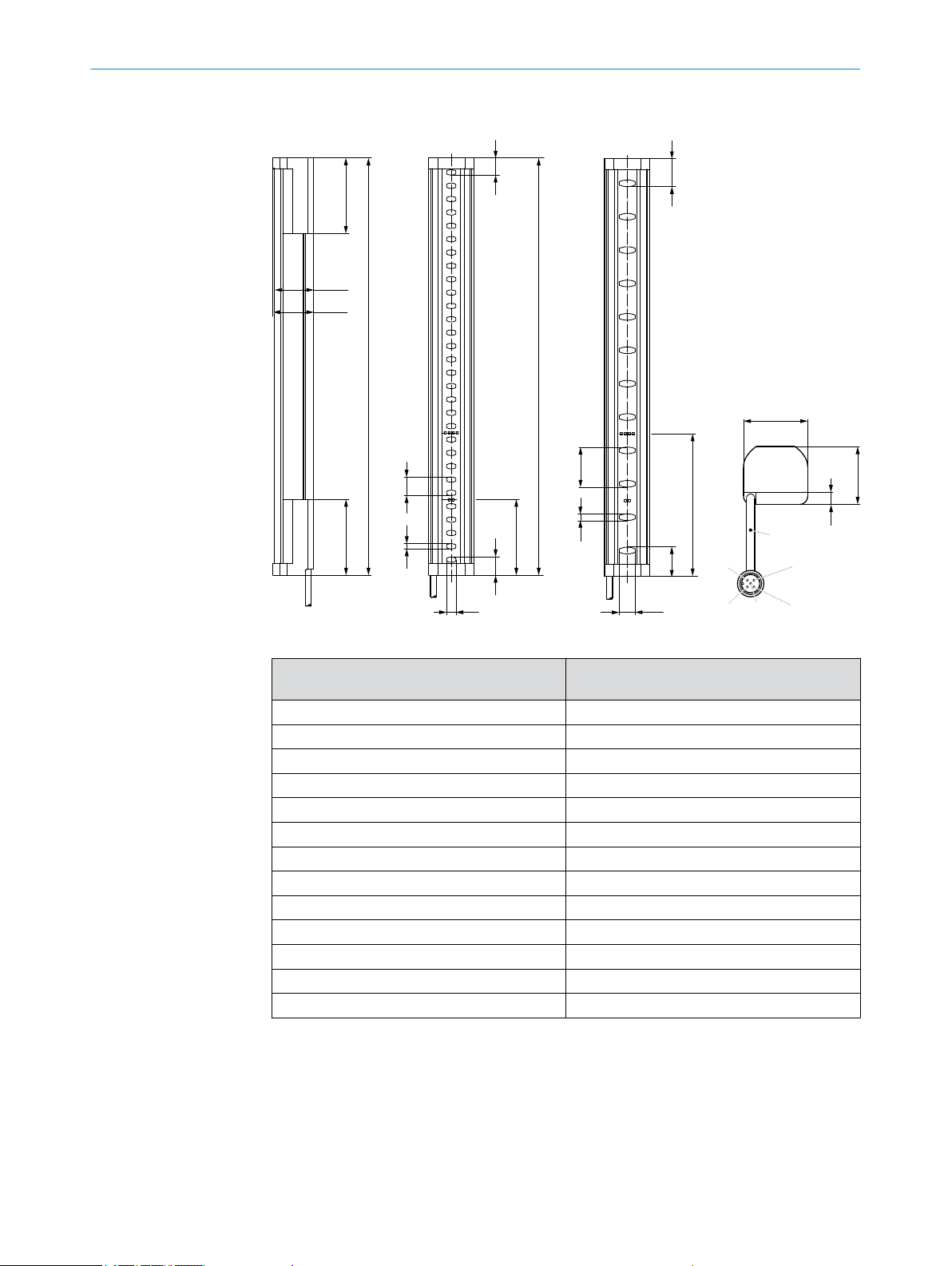
12.5 Dimensional drawings
5
30
4
14
56,8
56,8
L
56,8
L
29,5
30,7
7 12
30,7
6,3
34
L=150
106,8
1
4
2
5
3
13
21,1
13,8
21,8
TECHNICAL DATA 12
Figure 31: Dimensional drawing, sender and receiver
Protective field height, nominal [mm] Protective field, effective = dimension L [mm]
1
300 313
450 463
600 613
750 763
900 913
1050 1063
1200 1213
1350 1362
1500 1512
1650 1662
1800 1812
1950 1962
2100 2112
Table 13: Dimensions based on the protective field height, sender and receiver
1
The effective protective field corresponds to the entire length of the housing. The test object defined in
the standard IEC 61496-1 is recognized over the entire length of the housing. The limits of the protective
field are identical to ends of the housing.
8014276/2014-02-18 | SICK
Subject to change without notice
O PE R AT I NG IN S TR U CT I ON S | deTec2 Core
51
Page 52

13 ORDERING INFORMATION
13 Ordering information
13.1 Scope of delivery
Items supplied, sender – Sender
– 2 ea. QuickFix bracket
Items supplied, receiver – Receiver
– 2 ea. QuickFix bracket
– Test rod with diameter corresponding to the resolution of the safety light curtain
– Label ”Important Information”
– Operating instructions on CD-ROM 2066639
13.2 Ordering information deTec2 Core
Protective field
height [mm]
Part number Type code Part number Type code
300 1213163 C2C-SA03010A10000 1213188 C2C-EA03010A10000
450 1213189 C2C-SA04510A10000 1213190 C2C-EA04510A10000
600 1213191 C2C-SA06010A10000 1213192 C2C-EA06010A10000
750 1213193 C2C-SA07510A10000 1213194 C2C-EA07510A10000
900 1213195 C2C-SA09010A10000 1213196 C2C-EA09010A10000
1050 1213197 C2C-SA10510A10000 1213198 C2C-EA10510A10000
1200 1213183 C2C-SA12010A10000 1213199 C2C-EA12010A10000
Ordering information deTec2 Core, resolution 14 mm
Sender Receiver
1)
Table 14: Ordering information deTec2 Core, resolution 14 mm
1)
For other protective fields up to 2100 mm, contact your SICK subsidiary.
Protective field
height [mm]
Part number Type code Part number Type code
300 1213200 C2C-SA03030A10000 1213184 C2C-EA03030A10000
450 1213202 C2C-SA04530A10000 1213203 C2C-EA04530A10000
600 1213204 C2C-SA06030A10000 1213205 C2C-EA06030A10000
750 1213206 C2C-SA07530A10000 1213207 C2C-EA07530A10000
900 1213208 C2C-SA09030A10000 1213209 C2C-EA09030A10000
1050 1213210 C2C-SA10530A10000 1213211 C2C-EA10530A10000
1200 1213212 C2C-SA12030A10000 1213213 C2C-EA12030A10000
1350 1213214 C2C-SA13530A10000 1213215 C2C-EA13530A10000
1500 1213216 C2C-SA15030A10000 1213217 C2C-EA15030A10000
1650 1213218 C2C-SA16530A10000 1213219 C2C-EA16530A10000
1800 1213220 C2C-SA18030A10000 1213221 C2C-EA18030A10000
1950 1213222 C2C-SA19530A10000 1213223 C2C-EA19530A10000
2100 1213201 C2C-SA21030A10000 1213164 C2C-EA21030A10000
Ordering information deTec2 Core, resolution 30 mm
Sender Receiver
Table 15: Ordering information deTec2 Core, resolution 30 mm
52
O PE R AT I NG IN S TR U CT I ON S | deTec2 Core 8014276/2014-02-18 | SICK
Subject to change without notice
Page 53

14 Accessories
14.1 Ordering information, accessories
ACCESSORIES 14
Connectors
Part Part number
Connecting cable1) M12, 5-pin (0.34 mm2)
DOL-1205-G02MC socket straight with 2m cable, open end 6025906
DOL-1205-G05MC socket straight with 5m cable, open end 6025907
DOL-1205-G10MC socket straight with 10m cable, open end 6025908
DOL-1205-G20MC socket straight with 20m cable, open end 6050247
DOL-1205-G30MC socket straight with 30m cable, open end 6050248
DOL-1205-G02MC socket angled with 2m cable, open end 6025909
DOL-1205-G05MC socket angled with 5m cable, open end 6025910
DOL-1205-G10MC socket angled with 10m cable, open end 6025911
Connection cable
DSL-1285GM25034KM1, connection cable, M12, 5-pin on M12, 8-pin 2070987
DSL-6187GM25034KM1, connection cable, M12, 5-pin on M26, 7-pin 2070988
DSL-6182GM25034KM1, connection cable, M12, 5-pin on M26, 12pin
Distribution list
DSC-1205T000025KM0, T distributor 6030664
Terminal with resistance
Terminal with resistance, 2.15 k
Power supplies
Output 24 V DC, 50 W (2,1 A), power supply NEC Class 2, SELV, PELV,
input 120–240 V AC (PS50WE24V)
Output 24 V DC, 95 W (3,9 A), power supply NEC Class 2, SELV, PELV,
input 100–120/220–240 V AC (PS95WE24V)
2070989
2073807
7028789
7028790
Alignment aid
Cleaning agent
8014276/2014-02-18 | SICK
Subject to change without notice
1)
Ambient operating temperature: Up to -30°C with fixed installation
Part Part number
Laser alignment aid AR60 1015741
Adapter 4070854
Part Part number
Anti-static plastic cleaner 5600006
SICK lens cloth 4003353
O PE R AT I NG IN S TR U CT I ON S | deTec2 Core
53
Page 54

14 ACCESSORIES
Bracket
QuickFix bracket
FlexFix bracket
Part Part number
BEF-3SHABPKU2, 2 ea. QuickFix bracket (included with delivery) 2066048
BEF-1SHABPKU4, 4 ea. FlexFix bracket 2066614
BEF-1SHAABBKU2, FlexFix bracket kit (2 x FlexFix bracket, 4 sliding
nuts, 4 screws, 4 washers)
BEF-1SHABP004, replacement bracket (kit with 4 brackets) 2071021
Figure 32: Dimensional drawing of the QuickFix bracket (2066048)
2073543
Figure 33: Dimensional drawing of the FlexFix bracket (2066614)
54
O PE R AT I NG IN S TR U CT I ON S | deTec2 Core 8014276/2014-02-18 | SICK
Subject to change without notice
Page 55

Replacement bracket
ACCESSORIES 14
14.2
Weld spark guard
Function and use The weld spark guard can be used to protect the front screen of the safety light curtain.
Ordering information
8014276/2014-02-18 | SICK
Subject to change without notice
Figure 34: Dimensional drawing of the replacement bracket
(2071021)
The weld spark guard reduces the scanning range of the system by 15 %.
Part Part number
Weld spark guard 2069268
O PE R AT I NG IN S TR U CT I ON S | deTec2 Core
55
Page 56

14 ACCESSORIES
Mounting
Figure 35: Mounting the weld spark guard
Clean the front screen.
1
Remove the carrier film
2
Mount the weld spark guard
3
Crop the excess length at the ends
4
14.3 Deflector mirror
Function and use Deflector mirrors can be used to shape the protective field to secure hazardous points
from multiple sides using a single safety light curtain.
DANGER
Risk of ineffectiveness of the protective device
Persons and parts of the body to be protected are not recognized in case of non-ob‐
servance.
Only mount deflector mirrors to solid walls or machine components. The position of
b
the deflector mirrors must not change after alignment.
Do not use deflector mirrors if contamination, beading water, condensation or frost
b
on the deflector mirrors is to be expected.
Make sure that the deflector mirrors are free of contamination, beading water, con‐
b
densation or frost at all times.
56
O PE R AT I NG IN S TR U CT I ON S | deTec2 Core 8014276/2014-02-18 | SICK
Subject to change without notice
Page 57
14.3.1 Mounting
ACCESSORIES 14
Figure 36: Example of use of deflector mirrors
To mount the deflector mirrors, use the included swivel mount brackets.
14.3.2 Change in scanning range using deflector mirrors
NOTE
The use of deflector mirrors reduces the scanning range depending on the number of
deflector mirrors in the protective field.
The information relates to 90° beam deflection per mirror and a protective field height
of 900 mm.
Model name Resolution Scanning
range, typi‐
1)
cal
PNS75, PNS125 14 mm 8 m 7.2 m 6.4 m
PNS75, PNS125 30 mm 12 m 10.7 m 9.6 m
Table 16: Scanning range with and without 1 or 2 deflector mirrors
1)
At a typical scanning range, there is a possibility that all four LEDs to indicate alignment quality do not
light up even when alignment is good.
14.3.3 Deflector mirror PNS75 - ordering information
Mirror height S [mm] Protective field height
[mm]
340 300 PNS75-034 1019414
490 450 PNS75-049 1019415
640 600 PNS75-064 1019416
790 750 PNS75-079 1019417
940 900 PNS75-094 1019418
1090 1050 PNS75-109 1019419
1240 1200 PNS75-124 1019420
Table 17: Ordering information, deflector mirror PNS75
Scanning range with
1 deflector mirror, typi‐
1)
cal
Scanning range with
2 deflector mirrors, typi‐
1)
cal
Type number Part number
8014276/2014-02-18 | SICK
Subject to change without notice
O PE R AT I NG IN S TR U CT I ON S | deTec2 Core
57
Page 58

14 ACCESSORIES
Mirror height S [mm] Protective field height
[mm]
1390 1350 PNS75-139 1019421
1540 1500 PNS75-154 1019422
1690 1650 PNS75-169 1019423
1840 1800 PNS75-184 1019424
Table 17: Ordering information, deflector mirror PNS75
14.3.4 Deflector mirror PSN125 - ordering information
Mirror height S [mm] Protective field height
[mm]
340 300 PNS125-034 1019425
490 450 PNS125-049 1019426
640 600 PNS125-064 1019427
790 750 PNS125-079 1019428
940 900 PNS125-094 1019429
1090 1050 PNS125-109 1019430
1240 1200 PNS125-124 1019431
1390 1350 PNS125-139 1019432
1540 1500 PNS125-154 1019433
1690 1650 PNS125-169 1019434
1840 1800 PNS125-184 1019435
Table 18: Ordering information, deflector mirror PSN125
Type number Part number
Type number Part number
14.4 Columns
Part Part number
Device columns
Column height 985 mm 2045490
Column height 1165 mm 2045641
Column height 1265 mm 2045642
Column height 1720 mm 2045643
Column height 2020 mm 2045644
Column height 2250 mm 2045645
Column height 2400 mm 2045646
Mirror columns
Column height 1285 mm, mirror height 900 mm 1043453
Column height 1720 mm, mirror height 1350 mm 1043454
Column height 2000 mm, mirror height 1650 mm 1043455
Column height 2200 mm, mirror height 1800 mm 1043456
Table 19: Ordering information, columns
58
O PE R AT I NG IN S TR U CT I ON S | deTec2 Core 8014276/2014-02-18 | SICK
Subject to change without notice
Page 59

14.5 Test rods
ACCESSORIES 14
Part Part number
Test rod 14 mm 2022599
Test rod 30 mm 2022602
Test rod holder 2052249
Table 20: Ordering information, test rods
8014276/2014-02-18 | SICK
Subject to change without notice
O PE R AT I NG IN S TR U CT I ON S | deTec2 Core
59
Page 60

15 LIST OF FIGURES
15 List of figures
Fig. 1. Sender and receiver.......................................................................................... 10
Fig. 2. Sender indicators.............................................................................................. 11
Fig. 3. Receiver indicators............................................................................................12
Fig. 4. Hazardous point protection.............................................................................. 13
Fig. 5. Access protection.............................................................................................. 13
Fig. 6. Hazardous area protection............................................................................... 14
Fig. 7. Minimum distance to hazardous point for orthogonal approach to protective
Fig. 8. Representation of the accessibility of ESPE by reaching over. Left: Protective
Fig. 9. Minimum distance to reflective surfaces........................................................ 19
Fig. 10. Graph, minimum distance from reflective surfaces........................................19
Fig. 11. The direction of transmission of systems in close proximity to each other is
Fig. 12. Dual-channel and isolated connection of OSSD1 and OSSD2.......................21
Fig. 13. No potential difference between load and protective device.........................21
Fig. 14. Schematic representation of operation with restart interlock....................... 22
Fig. 15. Connection diagram for UE48-2OS with restart interlock and external device
Fig. 16. Sender and receiver must not be installed at 180° rotated relative to each
Fig. 17. Mount QuickFix bracket to a profile ................................................................ 27
Fig. 18. Mount FlexFix bracket to a profile frame.........................................................28
Fig. 19. Inserting the safety light curtain in the FlexFix brackets................................ 29
Fig. 20. Mount FlexFix bracket to a device column (accessory).................................. 30
Fig. 21. Replacement bracket, installation version A...................................................31
Fig. 22. Replacement bracket, installation version B...................................................31
Fig. 23. Replacement bracket, installation version C...................................................32
Fig. 24. Connection of OSSD1 and OSSD2................................................................... 33
Fig. 25. No potential difference between load and protective device ........................34
Fig. 26. Sender and receiver.......................................................................................... 34
Fig. 27. QuickFix bracket: adjust vertically....................................................................36
Fig. 28. FlexFix bracket: adjust vertically / rotate.........................................................37
Fig. 29. Daily checks of the protective device: Step 1..................................................40
Fig. 30. Daily checks of the protective device: Step 2..................................................41
Fig. 31. Dimensional drawing, sender and receiver..................................................... 51
Fig. 32. Dimensional drawing of the QuickFix bracket (2066048)............................. 54
Fig. 33. Dimensional drawing of the FlexFix bracket (2066614)................................ 54
Fig. 34. Dimensional drawing of the replacement bracket (2071021)...................... 55
Fig. 35. Mounting the weld spark guard........................................................................56
Fig. 36. Example of use of deflector mirrors.................................................................57
field.....................................................................................................................17
field that cannot be reached over. Right: Protective field that can be reached
over.....................................................................................................................18
reversed. The sender of the 2nd system is not affected by the beams 1st
system................................................................................................................ 20
monitoring.......................................................................................................... 23
other................................................................................................................... 25
60
O PE R AT I NG IN S TR U CT I ON S | deTec2 Core 8014276/2014-02-18 | SICK
Subject to change without notice
Page 61

16 List of tables
Tab. 1. Formula for calculating the minimum distance from reflective surfaces......19
Tab. 2. Device connection pin assignment (M12, 5-pin)............................................ 34
Tab. 3. Blue LEDs to indicate the alignment quality....................................................37
Tab. 4. Fault indicator on the sender........................................................................... 44
Tab. 5. Fault indicator on the receiver..........................................................................45
Tab. 6. General system data......................................................................................... 47
Tab. 7. Technical specifications, sender...................................................................... 48
Tab. 8. Technical specifications, receiver.................................................................... 48
Tab. 9. Operating data................................................................................................... 49
Tab. 10. Response time dependent on the protective field height.............................. 49
Tab. 11. Power consumption, sender and receiver....................................................... 50
Tab. 12. Weight of sender and receiver .........................................................................50
Tab. 13. Dimensions based on the protective field height, sender and receiver........51
Tab. 14. Ordering information deTec2 Core, resolution 14 mm...................................52
Tab. 15. Ordering information deTec2 Core, resolution 30 mm...................................52
Tab. 16. Scanning range with and without 1 or 2 deflector mirrors.............................57
Tab. 17. Ordering information, deflector mirror PNS75................................................ 57
Tab. 18. Ordering information, deflector mirror PSN125..............................................58
Tab. 19. Ordering information, columns.........................................................................58
Tab. 20. Ordering information, test rods........................................................................ 59
LIST OF TABLES 16
8014276/2014-02-18 | SICK
Subject to change without notice
O PE R AT I NG IN S TR U CT I ON S | deTec2 Core
61
Page 62

17 APPENDIX
17 Appendix
17.1 Compliance with EC directives
EC Declaration of Con‐
formity, page 1
62
O PE R AT I NG IN S TR U CT I ON S | deTec2 Core 8014276/2014-02-18 | SICK
Subject to change without notice
Page 63

EC Declaration of Con‐
formity, page 2
APPENDIX 17
8014276/2014-02-18 | SICK
Subject to change without notice
O PE R AT I NG IN S TR U CT I ON S | deTec2 Core
63
Page 64

17 APPENDIX
17.2 Checklist for initial commissioning and commissioning
Checklist for manufacturers/installersinstalling electro-sensitive protectivedevices
(ESPE)
The details on the items listed below must be available at the latest when the system is
commissioned for the first time, depending, however, on the various applications the
requirements of which must be reviewed by the manufacturer/installer.
This checklist should be retained and kept with the machine documentation to serve as
reference during recurring tests.
This checklist does not replace the initial commissioning, nor the regular inspection by
qualified safety personnel.
Have the safety rules and regulations been observed in compliance with the di‐
rectives/standards applicable to the machine?
Are the applied directives and standards listed in the declaration of conformity? Yes No
Does protective device comply with the required PL/SILCL and PFHd in accord‐
ance with EN ISO 13849-1/EN 62061 and type acc. to EN 61496-1?
Is the access to the hazardous area/hazardous point only possible through the
protective field of the ESPE?
Have appropriate measures been taken to prevent (mechanical point-of-opera‐
tion guarding) or monitor unprotected presence in the hazardous area when
protecting a hazardous area/hazardous point and have these been secured
against removal?
Are additional mechanical protective measures fitted and secured against ma‐
nipulation which prevent reaching below, above or around the ESPE?
Has the maximum shutdown and/or stopping time of the machine been meas‐
ured, specified and documented (at the machine and/or in the machine docu‐
mentation)?
Has the ESPE been mounted such that the required minimum distance from the
nearest hazardous point has been achieved?
Are the ESPE devices properly mounted and secured against manipulation after
adjustment?
Are the required protective measures against electric shock in effect (protection
class)?
Is the control switch for resetting the protective devices (ESPE) or restarting the
machine present and correctly installed?
Are the outputs of the ESPE (OSSD) integrated according to required PL/SILCL
compliant with EN ISO 13849-1/EN 62061 and does the integration corre‐
spond to the comply with the circuit diagrams?
Has the protective function been checked in compliance with the test notes of
this documentation?
Are the given protective functions effective at every setting of the operating
mode selector switch?
Are the switching elements activated by the ESPE, e.g. contactors, valves, moni‐
tored?
Is the ESPE effective over the entire period of the dangerous state? Yes No
Once initiated, will a dangerous state be stopped when switching the ESPE on
or off and when changing the operating mode, or when switching to another
protective device?
Has the ”Important Information” label for the daily check been attached such
that it is well visible for the operator?
Yes No
Yes No
Yes No
Yes No
Yes No
Yes No
Yes No
Yes No
Yes No
Yes No
Yes No
Yes No
Yes No
Yes No
Yes No
Yes No
64
O PE R AT I NG IN S TR U CT I ON S | deTec2 Core 8014276/2014-02-18 | SICK
Subject to change without notice
Page 65

APPENDIX 17
8014276/2014-02-18 | SICK
Subject to change without notice
O PE R AT I NG IN S TR U CT I ON S | deTec2 Core
65
Page 66

17 APPENDIX
66
O PE R AT I NG IN S TR U CT I ON S | deTec2 Core 8014276/2014-02-18 | SICK
Subject to change without notice
Page 67

APPENDIX 17
8014276/2014-02-18 | SICK
Subject to change without notice
O PE R AT I NG IN S TR U CT I ON S | deTec2 Core
67
Page 68

More representatives and agencies
at www.sick.com
Australia
Phone
+61 3 9457 0600
1800 334 802 – tollfree
E-Mail sales@sick.com.au
Belgium/Luxembourg
Phone +32 (0)2 466 55 66
E-Mail info@sick.be
Brasil
Phone +55 11 3215-4900
E-Mail sac@sick.com.br
Canada
Phone +1 905 771 14 44
E-Mail information@sick.com
Česká republika
Phone +420 2 57 91 18 50
E-Mail sick@sick.cz
China
Phone +86 4000 121 000
E-Mail info.china@sick.net.cn
Phone +852-2153 6300
E-Mail ghk@sick.com.hk
Danmark
Phone +45 45 82 64 00
E-Mail sick@sick.dk
Deutschland
Phone +49 211 5301-301
E-Mail info@sick.de
España
Phone +34 93 480 31 00
E-Mail info@sick.es
France
Phone +33 1 64 62 35 00
E-Mail info@sick.fr
Great Britain
Phone +44 (0)1727 831121
E-Mail info@sick.co.uk
India
Phone +91–22–4033 8333
E-Mail info@sick-india.com
Israel
Phone +972-4-6881000
E-Mail info@sick-sensors.com
Italia
Phone +39 02 27 43 41
E-Mail info@sick.it
Japan
Phone +81 (0)3 3358 1341
E-Mail support@sick.jp
Magyarország
Phone +36 1 371 2680
E-Mail office@sick.hu
Nederland
Phone +31 (0)30 229 25 44
E-Mail info@sick.nl
Norge
Phone +47 67 81 50 00
E-Mail sick@sick.no
Österreich
Phone +43 (0)22 36 62 28 8-0
E-Mail office@sick.at
Polska
Phone +48 22 837 40 50
E-Mail info@sick.pl
România
Phone +40 356 171 120
E-Mail office@sick.ro
Russia
Phone +7-495-775-05-30
E-Mail info@sick.ru
Schweiz
Phone +41 41 619 29 39
E-Mail contact@sick.ch
Singapore
Phone +65 6744 3732
E-Mail sales.gsg@sick.com
Slovenija
Phone +386 (0)1-47 69 990
E-Mail office@sick.si
South Africa
Phone +27 11 472 3733
E-Mail info@sickautomation.co.za
South Korea
Phone +82 2 786 6321/4
E-Mail info@sickkorea.net
Suomi
Phone +358-9-25 15 800
E-Mail sick@sick.fi
Sverige
Phone +46 10 110 10 00
E-Mail info@sick.se
Taiwan
Phone +886 2 2375-6288
E-Mail sales@sick.com.tw
Türkiye
Phone +90 (216) 528 50 00
E-Mail info@sick.com.tr
United Arab Emirates
Phone +971 (0) 4 88 65 878
E-Mail info@sick.ae
USA/México
Phone +1(952) 941-6780
1 (800) 325-7425 – tollfree
E-Mail info@sickusa.com
8014276/2014-02-18
SICK AG | Waldkirch | Germany | www.sick.com
 Loading...