

Page 1
Title Page
Analyzer Module DEFOR
for Series GMS800
Description
Operating Functions
Technical Data
SUPPLEMENTARY OPERATING INSTRUCTIONS
Page 2
Document Information
Glossary
Described Product
Product name: Analyzer Module DEFOR
Basic device: Series GMS800 gas analyzers
Document ID
Title: Supplementary Operating Instructions DEFOR
Part No.: 8013029
Version: 2.0
Release: 2012-12
Manufacturer
SICK AG
Erwin-Sick-Str. 1 · D-79183 Waldkirch · Germany
Phone: +49 7641 469-0
Fax: +49 7641 469-1149
E-mail: info.pa@sick.de
Trademarks
Viton is a trademark of DuPont Performance Elastomers.
Other product names used in this document may be trademarks
and are only used for identification purposes.
Original documents
The English edition 8013029 of this document is an original document of the manufacturer.
SICK AG assumes no liability for the correctness of an unauthorized translation.
Please contact the manufacturer in case of doubt.
Legal information
Subject to change without notice
Cl
2
S Hydrogen sulfide
H
2
IFC Interference Filter Correlation: Optical measure-
NH
3
NO Nitrogen monoxide
NO
2
SO
2
SOPAS SICK Open Portal for Applications and Systems:
SOPAS ET SOPAS Engineering Tool: PC application program to
PC Personal Computer
PTFE Polytetrafluorethylene
PVDF Polyvinylidene fluoride
Chlorine (gaseous)
ment method using two wavelength ranges.
Ammonia (gaseous)
Nitrogen dioxide
Sulphur dioxide
Family of computer programs to set parameters,
capture and calculate data.
configure modular system components.
Warning Symbols
Hazard (general)
Hazard by corrosive substances
© SICK AG. All rights reserved.
Hazard by high temperature or hot surfaces
Signal Words
CAUTION
Hazard or unsafe practice which could result in personal injury or
property damage.
NOTICE
Hazard which could result in property damage.
Information Symbols
Important technical information for this product
Nice to know
Supplementary information
Link to information at another place
2 DEFOR · Supplementary Operating Instructions · 8013029 V2.0 · © SICK AG
Page 3

Contents
Contents
1Important Information . . . . . . . . . . . . . . . . . . . . . . . . . . . . . . . . . . . . . . . . . . . . . . . 5
1.1 Main operating information. . . . . . . . . . . . . . . . . . . . . . . . . . . . . . . . . . . . . . . . . . . . . . . . . . . . 6
1.1.1 Noises . . . . . . . . . . . . . . . . . . . . . . . . . . . . . . . . . . . . . . . . . . . . . . . . . . . . . . . . . . . . . . . . . . . . 6
1.1.2 UV lamp service life . . . . . . . . . . . . . . . . . . . . . . . . . . . . . . . . . . . . . . . . . . . . . . . . . . . . . . . . 6
1.2 Application limitations . . . . . . . . . . . . . . . . . . . . . . . . . . . . . . . . . . . . . . . . . . . . . . . . . . . . . . . . 6
1.3 Additional documentation/information . . . . . . . . . . . . . . . . . . . . . . . . . . . . . . . . . . . . . . . . . 6
2 Product Description . . . . . . . . . . . . . . . . . . . . . . . . . . . . . . . . . . . . . . . . . . . . . . . . . . . 7
2.1 Measuring system . . . . . . . . . . . . . . . . . . . . . . . . . . . . . . . . . . . . . . . . . . . . . . . . . . . . . . . . . . . . 9
2.2 Options . . . . . . . . . . . . . . . . . . . . . . . . . . . . . . . . . . . . . . . . . . . . . . . . . . . . . . . . . . . . . . . . . . . . .10
2.2.1 Adjustment unit . . . . . . . . . . . . . . . . . . . . . . . . . . . . . . . . . . . . . . . . . . . . . . . . . . . . . . . . . . . 10
2.2.2 Process cuvette. . . . . . . . . . . . . . . . . . . . . . . . . . . . . . . . . . . . . . . . . . . . . . . . . . . . . . . . . . . 10
3 Installation Information. . . . . . . . . . . . . . . . . . . . . . . . . . . . . . . . . . . . . . . . . . . . . 11
3.1 Sample gas feed . . . . . . . . . . . . . . . . . . . . . . . . . . . . . . . . . . . . . . . . . . . . . . . . . . . . . . . . . . . . 12
3.2 Purge gas feed for process cuvette . . . . . . . . . . . . . . . . . . . . . . . . . . . . . . . . . . . . . . . . . . . .12
4 Functions in SOPAS ET . . . . . . . . . . . . . . . . . . . . . . . . . . . . . . . . . . . . . . . . . . . . . .13
4.1 Menu tree in SOPAS ET . . . . . . . . . . . . . . . . . . . . . . . . . . . . . . . . . . . . . . . . . . . . . . . . . . . . . . 14
4.2 Explanation of the menus in SOPAS ET . . . . . . . . . . . . . . . . . . . . . . . . . . . . . . . . . . . . . . . .16
4.3 Explanation of functions . . . . . . . . . . . . . . . . . . . . . . . . . . . . . . . . . . . . . . . . . . . . . . . . . . . . . 18
4.3.1 Logbook in SOPAS ET. . . . . . . . . . . . . . . . . . . . . . . . . . . . . . . . . . . . . . . . . . . . . . . . . . . . . . 18
4.3.2 Upload (data synchronization) . . . . . . . . . . . . . . . . . . . . . . . . . . . . . . . . . . . . . . . . . . . . . .18
4.3.3 Damping . . . . . . . . . . . . . . . . . . . . . . . . . . . . . . . . . . . . . . . . . . . . . . . . . . . . . . . . . . . . . . . . . 19
4.3.4 Drift limit values . . . . . . . . . . . . . . . . . . . . . . . . . . . . . . . . . . . . . . . . . . . . . . . . . . . . . . . . . . 20
4.3.5 Deleting adjustment results . . . . . . . . . . . . . . . . . . . . . . . . . . . . . . . . . . . . . . . . . . . . . . . .20
4.4 Adjustment Information . . . . . . . . . . . . . . . . . . . . . . . . . . . . . . . . . . . . . . . . . . . . . . . . . . . . . . 21
5Technical Data . . . . . . . . . . . . . . . . . . . . . . . . . . . . . . . . . . . . . . . . . . . . . . . . . . . . . . . . 23
5.1 Installation location requirements . . . . . . . . . . . . . . . . . . . . . . . . . . . . . . . . . . . . . . . . . . . . 24
5.2 Metrological specifications . . . . . . . . . . . . . . . . . . . . . . . . . . . . . . . . . . . . . . . . . . . . . . . . . . . 24
5.3 Technical gas specifications . . . . . . . . . . . . . . . . . . . . . . . . . . . . . . . . . . . . . . . . . . . . . . . . . .25
5.3.1 Sample gas. . . . . . . . . . . . . . . . . . . . . . . . . . . . . . . . . . . . . . . . . . . . . . . . . . . . . . . . . . . . . . . 25
5.3.2 Purge gas . . . . . . . . . . . . . . . . . . . . . . . . . . . . . . . . . . . . . . . . . . . . . . . . . . . . . . . . . . . . . . . .25
5.4 Materials with sample gas contact . . . . . . . . . . . . . . . . . . . . . . . . . . . . . . . . . . . . . . . . . . . . 25
5.5 Measuring ranges . . . . . . . . . . . . . . . . . . . . . . . . . . . . . . . . . . . . . . . . . . . . . . . . . . . . . . . . . . 26
5.6 Approvals . . . . . . . . . . . . . . . . . . . . . . . . . . . . . . . . . . . . . . . . . . . . . . . . . . . . . . . . . . . . . . . . . . . 26
5.7 UV lamp . . . . . . . . . . . . . . . . . . . . . . . . . . . . . . . . . . . . . . . . . . . . . . . . . . . . . . . . . . . . . . . . . . . .26
5.8 Auxiliary power supply for the module . . . . . . . . . . . . . . . . . . . . . . . . . . . . . . . . . . . . . . . . . 26
DEFOR · Supplementary Operating Instructions · 8013029 V2.0 · © SICK AG 3
Page 4

Contents
4 DEFOR · Supplementary Operating Instructions · 8013029 V2.0 · © SICK AG
Page 5

Important Information
DEFOR
1 Important Information
Operating information
Application limitations
Additional documentation
Subject to change w ithout notice
DEFOR · Supplementary Operating Instructions · 8013029 V2.0 · © SICK AG 5
Page 6
1.1 Main operating information
1.1.1 Noises
● Rhythmic noises are normal during operation.
● Specific noises can occur for several minutes after start-up.
1.1.2 UV lamp service life
The Analyzer module DEFOR uses a UV lamp as light source. The UV lamp has a limited service life and probably needs to be replaced several times during the overall operating time.
Status messages of increasing importance are activated automatically when the light
intensity of the UV lamp weakens (→ p. 16 [7]).
● UV lamp service life → p. 26, §5.7
● Display of the operating hours with the PC software “SOPAS ET” → p. 14,
§4.1
1.2 Application limitations
It is possible that another gas component contained in the sample gas can influence the
analysis of the desired measuring component (cross-sensitivity).
In such a case, a constant concentration of the “interfering gas” creates a constant deviation from the true measured value every time (constant characteristic curve offset). The
deviation varies accordingly when the interfering gas concentration fluctuates.
Important Information
● Cross-sensitivity against a certain gas is minimized automatically when the
DEFOR also measures the concentration of this gas.
● The cross-sensitivity can be minimized through computation in the control
unit when the interfering gas concentration is measured with a different
Analyzer module in the GMS800.
1.3 Additional documentation/information
This document supplements the Operating Instructions for GMS800 gas analyzers. It
extends the “GMS800“ Operating Instructions with technical information on the DEFOR.
▸
Observe the delivered “GMS800” Operating Instructions.
The “GMS800” Operating Instructions also specify all further documents
belonging to the individual device.
NOTICE:
▸
Pay primary attention to any individual information provided.
6 DEFOR · Supplementary Operating Instructions · 8013029 V2.0 · © SICK AG
Subject to change w ithout notice
Page 7

Product Description
DEFOR
2 Product Description
Measuring principle
Measuring ranges
Subject to change w ithout notice
DEFOR · Supplementary Operating Instructions · 8013029 V2.0 · © SICK AG 7
Page 8

Fig. 1 Measuring principle
M
M M
M M
IFC IFC + UVRAS UVRAS
1UV lamp
2 Filter wheel unit
2a Filter wheel 1
2b Filter wheel 2
3 Collimator lens
4 Beam splitter
5Mirror
6 Sample cuvette
[1]
[1] Length = 0.4/1.5/5.6/21/80/300 mm, depending on the measuring range
7 Reference cuvette
[1]
8 Converging lens
9 Detector
10 Adjustment unit
M Motor
2a
1
3
4
5
2b
6
7
8 9
10
2a
2b
Product Description
M
M
8 DEFOR · Supplementary Operating Instructions · 8013029 V2.0 · © SICK AG
Subject to change w ithout notice
Page 9
Product Description
2.1 Measuring system
Measuring principle
The Analyzer module DEFOR uses the fact that some gases have a specific absorption
characteristic in the ultraviolet light range. For this purpose, UV light is radiated through the
sample gas. The concentration of a gas component in a gas mixture can be determined
through suitable selection of the light wavelength and selective absorption measurement.
The Analyzer module DEFOR can, in this way, analyze the concentration of the gases Cl
H
S, NO, NO2, NH3, SO2 and further gases.
2
The Analyzer module DEFOR can simultaneously measure up to 3 gas components.
Measuring method
● The Analyzer module DEFOR uses interference filter correlation (IFC) for most gas components. Measuring and reference radiation are created alternately by swiveling two different interference filters into the beam path (filter wheel [2a]).
● Gas filter correlation (UVRAS) is used for NO. This method creates the reference radiation by swiveling a gas filter filled with the relevant gas into the beam path (filter wheel
[2b]).
● Both measuring methods are combined for joint measurement of NO and other gases
(both filter wheels [2a]+[2b] are used).
● The physical state of the measuring system is captured and compensated using a reference beam path through a reference cuvette.
,
2
Analyzer module layout
– Beam source is a special UV gas discharge lamp (→ p. 8, Fig. 1 [1]) that emits both broad-
band as well as NO-specific radiation components.
– Thermostat-controlled filter wheel unit [2] keeps the optic filters at a constant tempera-
ture. This minimizes the influence of external temperature changes.
– Lenses [3][8], beam splitter [4] and mirror [5] direct the beam path.
– Sample gas flows through sample cuvette [6]. Reference cuvette [7] is either filled with
a neutral gas or has span gas flowing through (option).
– Detectors [9] capture the radiation intensity created with the various filters.
– Measurement signals are amplified electronically and digitally evaluated. The structure
symmetry compensates proportional and symmetric signal drifts in the best possible
way.
–The measuring system can be fitted with an adjustment unit ([10] → p. 10, § 2.2.1).
The specific properties of the desired measuring components and the desired
physical measuring range each demand an individual metrological concept for
the Analyzer module.
Subject to change w ithout notice
DEFOR · Supplementary Operating Instructions · 8013029 V2.0 · © SICK AG 9
Page 10

2.2 Options
A
A
A A
1 Purge gas compartment
2 Measuring compar tment
3 Purge gas compartment
4 Process cuvette
5 Spacer tube
6 Reference cuvette
41 2 3 65
2.2.1 Adjustment unit
The adjustment unit simplifies and accelerates routine adjustments.
Zero gas flows through the Analyzer module during an adjustment procedure with an
adjustment unit. The first step is a zero point adjustment. An optical filter is swiveled automatically into the beam path of the sample cuvette for the subsequent reference point
adjustment – and thus simulates the presence of a span gas in the sample cuvette. The
nominal values of this simulation are determined at the manufacturer's factory.
This means only a zero gas is required for an adjustment procedure with adjustment unit; a
span gas for reference point adjustment is not necessary. The procedure can be started
manually or can run automatically (requires automated zero gas feed).
The adjustment unit should be checked and readjusted in larger intervals during operation (recommendation: Every 6 months). For this purpose, the Analyzer module must be adjusted with real test gases beforehand.
2.2.2 Process cuvette
The versions with process cuvette are intended for applications with dangerous sample
gases where it must be ensured the sample gas does not flow into the gas analyzer when a
window of the sample cuvette becomes leaky.
In the process cuvette, the measuring compartment is flanked by purge gas compartments
through which purge gas flows continuously (→ Fig. 2). When a measuring compartment
window is leaky, the emerging sample gas flows into the purge gas compartment and from
there out of the gas analyzer with the purge gas.
The GMS800 therefore requires continuous purge gas for versions with a process cuvette
(→ p. 12, §3.2).
Product Description
Fig. 2 Process cuvette
Subject to change w ithout notice
10 DEFOR · Supplementary Operating Instructions · 8013029 V2.0 · © SICK AG
Page 11

Installation Information
DEFOR
3 Installation Information
Sample gas feed
Purge gas feed for process cuvette
Subject to change w ithout notice
DEFOR · Supplementary Operating Instructions · 8013029 V2.0 · © SICK AG 11
Page 12

3.1 Sample gas feed
▸
Observe the information on sample gas feed in the “Series GMS800” Operating Instructions.
3.2 Purge gas feed for process cuvette
Only valid for versions with process cuvette (option → p. 10, §2.2.2 )
In versions with process cuvette, the GMS800 enclosure has additional “purge gas inlet”
und “purge gas outlet” gas connections.
Gas connections type and version → Supplementary Operating Instructions for
Enclosure
1 Install an external continuous purge gas supply for GMS800.
Suitable purge gas: Chemically neutral gas (inert gas) or gas mixture suitable for diluting and transporting the measured gas without danger.
2 Feed the purge gas through the “purge gas inlet“ gas connection on the enclosure.
Allowable pressure and volume flow: → p. 25, §5.3.2
3 Install a gas line on the “purge gas outlet” through which the purge gas and emerged
sample gas are reliably discharged.
▸
Lead the gas line to a safe position where emerged sample gas cannot create any
danger.
▸
Recommendation: Attach appropriate warning signs to the gas line or gas outlet
informing about the hazardousness of the sample gas.
Installation Information
12 DEFOR · Supplementary Operating Instructions · 8013029 V2.0 · © SICK AG
Subject to change w ithout notice
Page 13
Functions in SOPAS ET
DEFOR
4 Functions in SOPAS ET
Menu functions in the PC program “SOPAS ET”
Menu tree
Explanations
● Instructions for the PC program “SOPAS ET” → User Information for the pro-
gram
● Exemplary menu representations → Technical Information “Basic Control
Unit (BCU)” (contains information for operating with SOPAS ET)
Subject to change w ithout notice
DEFOR · Supplementary Operating Instructions · 8013029 V2.0 · © SICK AG 13
Page 14
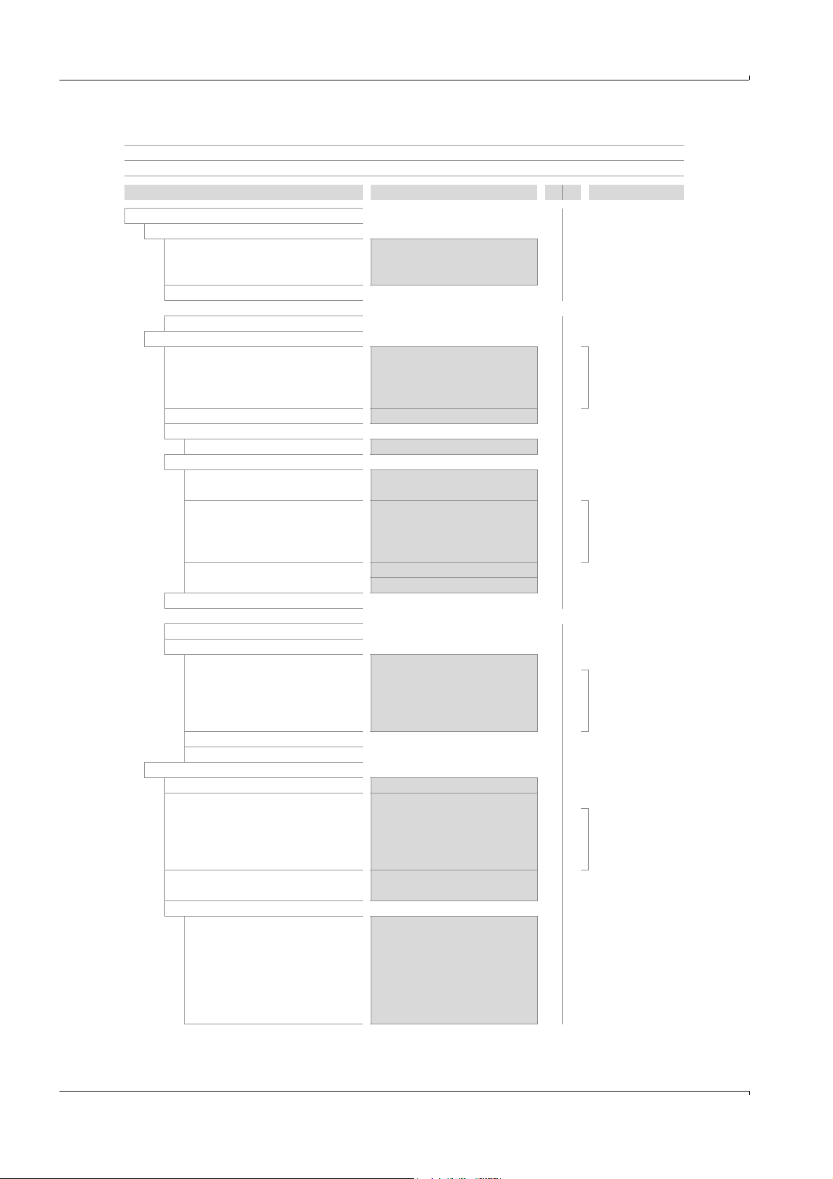
4.1 Menu tree in SOPAS ET
User level: O Operator (standard) A Authorized operator
Access rights: ○ Viewing ● Setting up/starting
Directory Menu contents O A Explanation
S800_DEFOR ○○
Measured value display ○○
Measuring component 1
Measuring component 2
[1]
↓
Measuring component 10
[1]
Diagnosis ○○
Module state Failure ○○
Logbook
Operating hours – ○
Lamp h–○→p. 16 [5]
Measuring component 1 ○○
Name / unit
State
Validation measurement (QAL3) Zero point ○○
Measuring component 2
[1]
↓
Measuring component 10
[1]
UV lamp – ○
Physical component 1
Physical component 2
Physical component 3
[1]
[1]
Parameter ○○
Sampling point
RS485 interface Module address – ○→p. 16 [9]
Operating mode
Measuring component 1 ○○
Physical meas. range
Functions in SOPAS ET
Component ○○ →p. 16 [1]
Measured value ○○ →p. 16 [2]
Unit ○○ →p. 16 [3]
○○
○○
Maintenance request ○○ →p. 16 [4]
Function(s) active ○○
Uncertain state ○○
Pos.|Date|Source| … – ○→p. 18, §4.3.1
Component ○● →p. 16 [1]
Unit ○○ →p. 16 [2]
Failure ○○
Maintenance request ○○ →p. 16 [4]
Function(s) active ○○
Uncertain state ○○
Reference point ○○
○○
○○
Intensity …% – ○→p. 16 [6]
Failure – ○
Uncertain – ○→p. 16 [7]
Maintenance – ○
OK – ○
– ○
– ○
Description – ●→p. 16 [8]
Baud rate – ●
Data bits – ●→p. 16 [10]
Stop bits – ●
Parity – ●
Actual – ○→p. 16 [11]
Tar get – ○→p. 16 [12]
Component ○● →p. 16 [1]
Unit ○○ →p. 16 [3]
Start value ○○ →p. 16 [13]
End value ○○ →p. 16 [14]
Base value ○○ →p. 16 [15]
Measuring channel ○○ →p. 16 [16]
Precision ○○ →p. 17 [17]
Subject to change w ithout notice
14 DEFOR · Supplementary Operating Instructions · 8013029 V2.0 · © SICK AG
Page 15

Functions in SOPAS ET
Directory Menu contents O A Explanation
Adjustment ○○
Maintenance – ○
Factory settings ○○
[1] If fitted.
Damping – ●
Damping (el. T90%) Time constant [s] – ●
Dynamic damping Status [On/Off] – ● → p. 19, § 4.3.3
Time constant [s] – ●
Threshold – ●
Measuring component 2
[1]
○○
↓
Measuring component 10
[1]
○○
Measuring component 1 ○○
Drift limit value
Zero point – ○→p. 20, § 4.3.4
Reference point – ○
Adjustment results ○○
Adjustment result Zero point ○○
Reference point ○○
Drifts Zero point ○○ →p. 17 [18]
Reference point ○○
Delete results
Measuring component 2
[1]
[Delete] – ●→p. 20, §4.3.5
○○
↓
Measuring component 10
[1]
○○
Maintenance flag [On]/[Off] – ●→p. 17 [20]
Settings – ○
User settings
[Backup] – ●
[Restore last user settings] – ●→p. 17 [21]
[Restore next to last user settings] – ●
Factory settings [Restore] – ●→p. 17 [22]
Identification ○○
ID numbers
Serial number ○○
Material No. ○○
Hardware version ○○ →p. 17 [23]
Software version ○○
Software date ○○
Production release
Year | Month | Day – ○→p. 17 [24]
Subject to change w ithout notice
DEFOR · Supplementary Operating Instructions · 8013029 V2.0 · © SICK AG 15
Page 16

4.2 Explanation of the menus in SOPAS ET
Description Explanation
No.
1 Component Name of measuring component
2 Measured value Actual measured value of measuring component
3 Unit Physical unit of measured value
4 Failure LED symbol
● Significance: Module not ready for operation
● Possible causes: Malfunction, defect
Maintenance request LED symbol
● Significance: Advance warning before internal technical
limits reached.
● Possible causes: Drift limit, operating hours, lamp intensity
Function(s) active LED symbol
● Significance: At least one internal function active that
impairs or hinders normal module measuring function.
● Possible causes: Adjustment procedure running, validation
measurement running
Uncertain state LED symbol
● Significance: Actual measured values are unreliable.
● Possible causes: Heating up phase, internal over/under
temperature, adjustment procedure programming not
plausible
5 Operating hours Number of operating hours of the UV lamp fitted
6 Intensity …% Actual light intensity in the reference beam path for the asso-
ciated measured component (with the specific optical filter in
the beam path) relative to the new condition of the UV lamp;
evaluated automatically (
5.7)
7 Failure UV lamp status (evaluation of intensity); “OK” = full intensity,
Uncertain
Maintenance
OK
“Maintenance” = UV lamp replacement recommended;
“Uncertain” = correct measuring function questionable; “Failure” = measurement no longer possible. The module status
flags are activated accordingly (
8 Description Freely selectable text for module name
9 Module address Internal CAN bus address of module (defined by hardware set-
ting in module)
10 Baud rate Transfer speed (standard: 9600)
Data bits Number of data bits (standard: 8)
The GMS800 only uses the 7-bit range (ASCII code 0 … 127)
but can also communicate in 8-bit format.
Stop bits Number of stop bits (1 or 2; standard: 2)
Parity Additional identification for automatic monitoring of character
transfers; [Even], [Odd], [None]. – Standard: None
11 Actual Internal operating module state:
● [Heating] = heating up phase (measured values unreliable)
● [Measuring] = measuring operation (normal operating
mode)
● [Halt] = stopped electronically (not ready for operation)
12 Target Default operating mode through entry or software function;
should become actual operating mode af ter a certain time
(can take up to 1 hour during the heating up time after start-
up).
13 Start value Start value of physical measuring range
14 End value End value of physical measuring range
15 Base value Internal physical base value of measuring range
16 Measuring channel Internal measuring channel for measuring component
Functions in SOPAS ET
→ [7]; UV lamp service life → p. 26,
→ [4]).
Subject to change w ithout notice
16 DEFOR · Supplementary Operating Instructions · 8013029 V2.0 · © SICK AG
Page 17

Functions in SOPAS ET
Description Explanation
No.
17 Precision [On] = higher measuring precision is available for measuring
range 2 (effective in range 0 … 20% of physical measuring
range)
18 Drifts
● Last = since last adjustment
● Total = since last drift calculation initialization
19 Delete results [Delete] = Set all drift values to “0”.
20 Maintenance flag [On] = Status “Maintenance” is activated (here as signal for
active maintenance work)
21 User settings
22 Factory settings Overwrite the actual module settings with the original settings
● Backup = save a copy of the actual module settings.
● Restore = overwrite the actual module settings with the
saved copy.
from the factory.
▸
Recommendation: Save the current module settings first
[1]
[1]
(→ “User settings”).
23 Serial number Individual module serial number
Material No. Identification number of module version
Hardware version Module electronics version number
Software version Module software version number
Software date Module software revision
24 Production release Module date of manufacture
[1] A warm star t is then done automatically.
Subject to change w ithout notice
DEFOR · Supplementary Operating Instructions · 8013029 V2.0 · © SICK AG 17
Page 18

4.3 Explanation of functions
1 2 3 4 5 6 7
4.3.1 Logbook in SOPAS ET
The Logbook Table shows the last 20 internal messages.
Fig. 3 Menu “[Module name]/Diagnosis/Logbook” in PC program “SOPAS-ET” (example)
Column Meaning
1 Sequential number in Logbook
2
Time of last message change
3
4 “System” = measuring system (hardware)
“MV” = measuring component (measurement)
5 Short message text, e.g. “F measured value”.
The character prefix classifies the message:
F = Failure
C = Check (adjustment/validation)
U = Uncertain (extra information)
M = Maintenance
E = Extended (status message)
6 Current message status
7 Total count of activations
Functions in SOPAS ET
4.3.2
Upload (data synchronization)
Only applicable when the “SOPAS ET” PC software is used. Not applicable for systems
without control unit (special versions).
The new data are not transferred automatically to “SOPAS ET” after settings for a module
have been changed with the menu functions of the control unit. “SOPAS ET” continues
using the previous data.
▸
To transfer the current data of a module to “SOPAS ET”: Start the “Upload all parame-
ters from device” function in “SOPAS ET” once.
18 DEFOR · Supplementary Operating Instructions · 8013029 V2.0 · © SICK AG
Subject to change w ithout notice
Page 19

Functions in SOPAS ET
4.3.3 Damping
Constant damping
When “damping” has been programmed, the average value from the current measured
value and the previous measured values (floating averaging) are displayed instead of the
current measured value.
Possible uses include:
– Damping metrological measured value fluctuations (noise)
– Smoothing fluctuating measured values when only the average value is relevant
Damping is done in the Analyzer module and therefore affects all measured value displays
and outputs. It is also active during an adjustment procedure.
● Increasing damping normally increases the reaction time (90% time) of the
gas analysis system accordingly.
● Reducing damping can possibly increase the measurement signal “noise”
(measuring turbulence).
● Time constant = 0 s means: No damping.
CAUTION: Risk of incorrect adjustment
The “Measuring time, test gas” must be at least 150% of the set damping time
constant during adjustments.
▸
When damping has been reset or increased: Check whether adjustment
settings need to be adapted.
Dynamic damping
“Dynamic damping” serves to compensate measured value fluctuations without significantly increasing the reaction time. Dynamic damping is automatically deactivated when
the measured value changes rapidly and strongly as against “normal” damping. This allows
“smoothing” continuous minor measured value fluctuations but rapid measured value
changes are still displayed without delay. Dynamic behavior is determined with the “Threshold” parameter:
– When the measured values change only slowly, dynamic damping functions as constant
damping.
– When the difference of successive measured values is greater than the set limit,
dynamic damping is terminated automatically and remains disabled as long as the
measured values continue to change rapidly.
– Dynamic damping is active again when measured value differences are below the limit
again (which means measured values changes remain slight).
Dynamic damping also affects all measured value displays and outputs.
Subject to change w ithout notice
DEFOR · Supplementary Operating Instructions · 8013029 V2.0 · © SICK AG 19
Page 20

4.3.4 Drift limit values
Purpose
Analyzer module drifts are caused, for example, by contamination, mechanical changes or
aging effects. The total drift (i.e. the deviation from original state) increases gradually. It is
not practical to keep compensating an ever increasing total drift through computation.
Inspect and reset the Analyzer module when total drift has become very large.
Drift limit values monitor total drift automatically. These also protect against erroneous
adjustments.
Functionality
After every adjustment, an Analyzer module compares the calculated total drift with the
drift limit value. Drift limit value violation is reported in two stages:
● Status “M” (Maintenance request) is activated when the total drift reaches 100 … 120%
of the drift limit value.
● Status “F” (Failure) is activated when the total drift reaches more than 120% of the drift
limit value.
● When an adjustment procedure shows that a calculated drift has reached more than
150% of the drift limit value, the result from this adjustment procedure is ignored and
the previous adjustment remains valid.
Functions in SOPAS ET
● The drift limit values are set in the factory (standard value: 10%).
● A Service function is available to reset all drift values to “0” (Drift reset).
This is useful after Analyzer module maintenance when this has established a new original state.
4.3.5 Deleting adjustment results
The “Delete results” function deletes all determined drift values of a measuring component. Drift limit values then refer to new drift values.
The data of the previous adjustment which was performed before are then no longer displayed. Test gas settings (e. g. nominal value) are not changed.
CAUTION: Risk of incorrect adjustment
If very large drift values are displayed after a manual adjustment procedure
(→ Operating Instructions “Basic Control Unit (BCU)”), a test gas used probably
did not match the relevant test gas setting or gas feed was interrupted – and
the adjustment result was still accepted.
▸
Do not delete incorrect adjustment results, but repeat the adjustment carefully.
▸
Do not use the deletion of adjustment results to nullify large drift values
caused by extensive physical changes of an Analyzer module. Instead,
clean the Analyzer module or perform an adjustment.
▸
After an Analyzer module has been cleaned, altered or exchanged:
Delete the relevant adjustment results and perform an adjustment.
[1] By the manufacturer's Customer Service or authorized skilled persons with appropriate training.
[1]
20 DEFOR · Supplementary Operating Instructions · 8013029 V2.0 · © SICK AG
Subject to change w ithout notice
Page 21

Functions in SOPAS ET
4.4 Adjustment Information
The control unit controls the adjustments.
▸
Individual adjustment of each shown measuring component and each measuring
range.
▸
Information concerning purpose, prerequisites and frequency of adjustments → Operat-
ing Instructions “Series GMS800”
▸
Programming of the adjustment parameters for each measuring component of the
GMS800 → Technical Information “Basic Control Unit (BCU)”
▸
Manual start of an adjustment procedure → Operating Instructions of the control unit
Subject to change w ithout notice
DEFOR · Supplementary Operating Instructions · 8013029 V2.0 · © SICK AG 21
Page 22

Functions in SOPAS ET
22 DEFOR · Supplementary Operating Instructions · 8013029 V2.0 · © SICK AG
Subject to change w ithout notice
Page 23

Technical Data
DEFOR
5 Technical Data
Ambient conditions
Sample gas specifications
Metrological specifications
Subject to change w ithout notice
DEFOR · Supplementary Operating Instructions · 8013029 V2.0 · © SICK AG 23
Page 24

5.1 Installation location requirements
Geographic height at installation location: ≤ 2500 m altitude
Ambient air pressure: 700 … 1200 hPa
Allowable oscillations/jolts
– Displacement: 0.035 mm (in range 5 … 59 Hz)
– Activation acceleration amplitude: 5 m·s
Usage position: Max. ±15° tilt to every spatial axis
[1] Higher altitudes can be realized (option); compensation for height influence.
[2] Allowable surface tilt during operation; keep constant during operation; readjust after changing the tilt.
5.2 Metrological specifications
Measured variable: Volume concentration of a gas component
Measuring ranges: See specification for individual device
Detection limit (2σ):
[3]
– Standard measuring ranges: < 0.5% of measurement span
– Small measuring ranges:
[4]
< 1% of measurement span
Linearity deviation: < 1% of measurement span
Zero point drift
– Standard measuring ranges: < 1% of measurement span per week
– Small measuring ranges:
– Measured components NO, NO
[4]
, SO2: < 1% of measurement span per day
2
< 2% of measurement span per week
Reference point drift: < 1% of measurement span per week
Ambient temperature influence:
– Standard measuring ranges: < 1%
– Small measuring ranges:
Setting time (t
): 4 s
90
[4]
< 2%
Run-in time: < 60 minutes
[1] → p. 26, § 5.5
[2] Possible measuring ranges → p. 26, § 5.5.
[3] Values valid with constant damping T
[4] Valid for measuring ranges < 2x smallest measuring range.
[5] Of respective measuring range.
[6] Typical value for sample gas volume flow = 60 l/h and T
=10s + dynamic damping T
T
90, el.
volume flow.
= 10 s; for measuring component NO: With constant damping
90, el.
=60s.
90, dyn.
90, el.
[1]
-2
(in range 59 … 160 Hz)
[2]
[1]
[2]
[5]
/10 K
[5]
/10 K
[6]
= 1 s; depending on cuvette length and sample gas
Technical Data
If not specified otherwise, the metrological specifications in relation to the
physical measuring range are applicable (see order documents). The physical
measuring range is usually identical with the largest measuring range. The
same values apply for all other measuring ranges.
If, however, the Analyzer module was manufactured with “higher measuring
precision” (option), measuring precision is increased in range 0 … 20% of the
physical measuring range. The measurement specifications in this range are
then applicable in relation to 20% of the physical measuring range.
24 DEFOR · Supplementary Operating Instructions · 8013029 V2.0 · © SICK AG
Subject to change w ithout notice
Page 25

Technical Data
5.3 Technical gas specifications
5.3.1 Sample gas
Allowable sample gas temperature:
– Minimum: 5 °C (41 °F)
– Maximum: 55°C (131°F)
Allowable sample gas dew point: Below ambient temperature
Particles in the sample gas: Sample gas should be free from dust and aerosols
Allowable sample gas pressure
Sample gas volume flow
[1]
– Minimum: 20 l/h (333 cm3/min)
– Maximum: 120 l/h (2000 cm
– Recommended: 30…60l/h (500…1000cm
– Standard: 30 l/h (500 cm
[1] On the sample gas inlet. Keep constant during operation.
[2] When a sample gas cooler is used: Always above the cooler temperature (dew point).
[3] With “heated sample gas path” option: Up to +80 °C, depending on the temperature set.
[4] On the sample gas inlet.
[5] Relative to the ambient/atmospheric air pressure.
[5]
[1]
[2]
[3]
–200 … +300 hPa (–0.2 … +0.3 bar)
3
/min)
3
/min)
3
/min)
[4]
5.3.2 Purge gas
Only valid for version with process cuvette (→ p. 10, §2.2.2)
Suitable purge gas: Dry inert gas (chemically neutral gas/gas mixture
without condensable components)
Allowable purge gas pressure
[1]
15 … _30 hPa
Purge gas volume flow
– Minimum: 20 l/h (333 cm
– Maximum: 100 l/h (167 cm
– Recommended: 20 … 60 l/h (333 … 1000 cm
– Standard: 30 l/h (500 cm
[1] Relative to the ambient/atmospheric air pressure.
5.4 Materials with sample gas contact
Component Material
Cuvette: Aluminium or stainless steel
Optical window: CaF2 or quartz
Synthetics: Viton B, PVDF, PTFE
[1] Depending on version.
3
3
[1]
/min)
3
/min)
/min)
[1]
[1]
3
/min)
Subject to change w ithout notice
DEFOR · Supplementary Operating Instructions · 8013029 V2.0 · © SICK AG 25
Page 26

5.5 Measuring ranges
Technical Data
Measuring
component
Cl
2
COS 250 670 – 100
CS
2
H
S 25 40 – 100
2
NH
3
NO 10 15 50 100
NO
2
SO
2
[1] Approvals→ p. 26, §5.6.
[2] For operation in air-conditioned environment (±2 °C temperature deviation) and daily zero point adjustment.
● Conversion from ppm to mg/m
● All specifications valid for a mixture of the measuring components and N
5.6 Approvals
Conformities DEFOR
EN 15267-3 ●
EN 14181 ●
2000/76/EC (17th BImSchV) ●
2001/80/EC (13th BImSchV) ●
27th BImSchV ●
Smallest measuring range Largest measuring
Technical Performance-
ppm mg/m
3
[1]
tested
ppm % by vol.
range
125 400 – 100
50 170 – 30
50 40 – 100
50 (10)
25 (10)
[2]
[2]
105 (20)
3
relative to 20°C, 1013 hPa.
75 (30)
[2]
[2]
50 100
75 100
.
2
5.7 UV lamp
Design: Electrode-less discharge lamp, EDL
Service life: Approx. 2 years (= 17500 hours)
5.8 Auxiliary power supply for the module
Voltage supply: 24 VDC
Power input: ≤ 134 W
Subject to change w ithout notice
26 DEFOR · Supplementary Operating Instructions · 8013029 V2.0 · © SICK AG
Page 27

Technical Data
··· Empty page ···
Subject to change w ithout notice
DEFOR · Supplementary Operating Instructions · 8013029 V2.0 · © SICK AG 27
Page 28

Keywords
Index
A
Actual (display) . . . . . . . . . . . . . . . . . . . . . . . . . . . . . 16
Adjustment result
Adjustment results
Approvals
Auxiliary power supply
. . . . . . . . . . . . . . . . . . . . . . . . . . . . . . . . . . 26
. . . . . . . . . . . . . . . . . . . . . . . . . . . 15
. . . . . . . . . . . . . . . . . . . . . . . . . . 15
. . . . . . . . . . . . . . . . . . . . . . . . 26
B
Backup (user settings) . . . . . . . . . . . . . . . . . . . . . . . 15
Backup copy (user settings)
Base value (display)
Baud rate
. . . . . . . . . . . . . . . . . . . . . . . . . . . . . . . . . . 16
. . . . . . . . . . . . . . . . . . . . . . . . . 16
. . . . . . . . . . . . . . . . . . . 15
C
Conformities . . . . . . . . . . . . . . . . . . . . . . . . . . . . . . . . 26
Constant damping
. . . . . . . . . . . . . . . . . . . . . . . . . . . 19
D
Damping
- Constant damping (el. T90%)
- Dynamic damping
-el.T90% (constant damping)
Data bits
Detection limit
Diagnosis
Drift
- Specifications
- Viewing actual values
- Viewing drift limit values
Drift limit values
- Purpose, functionality
Dynamic damping
. . . . . . . . . . . . . . . . . . . . . . . . . . . . . . . . . . . 16
. . . . . . . . . . . . . . . . . . . . . . . . . . . . . . . . . . 14
. . . . . . . . . . . . . . . . . . . . . 15, 19
. . . . . . . . . . . . . . . . . . . . . . . . . . . . . . 24
. . . . . . . . . . . . . . . . . . . . . . . . . . . . . 24
. . . . . . . . . . . . . . . . . . . . . . 15
. . . . . . . . . . . . . . . . . . . . . . . . . . . . . 20
. . . . . . . . . . . . . . . . . . . . . . 20
. . . . . . . . . . . . . . . . . . . . . . . 15, 19
. . . . . . . . . . . . . . . . 19
. . . . . . . . . . . . . . . . 15
. . . . . . . . . . . . . . . . . . . . 15
E
el. T90% (constant damping) . . . . . . . . . . . . . . . . . . 19
End value (display)
. . . . . . . . . . . . . . . . . . . . . . . . . . 16
F
Factory settings, restoring . . . . . . . . . . . . . . . . . . . . 15
Failure
. . . . . . . . . . . . . . . . . . . . . . . . . . . . . . . . . . . . 16
FICA
. . . . . . . . . . . . . . . . . . . . . . . . . . . . . . . . . . . . . . 26
Filter wheel
Flow (volume flow)
- Purge gas
-Sample gas
Function(s) active
Functions in SOPAS ET
. . . . . . . . . . . . . . . . . . . . . . . . . . . . . . . . . . 9
. . . . . . . . . . . . . . . . . . . . . . . . . . . . . . . . 25
. . . . . . . . . . . . . . . . . . . . . . . . . . . . . . . 25
. . . . . . . . . . . . . . . . . . . . . . . . . . . 16
. . . . . . . . . . . . . . . . . . . . . . . 13
G
Gas filter correlation . . . . . . . . . . . . . . . . . . . . . . . . . . 9
Glossary
. . . . . . . . . . . . . . . . . . . . . . . . . . . . . . . . . . . . 2
H
Hardware version (display) . . . . . . . . . . . . . . . . . . . . 15
I
ID numbers . . . . . . . . . . . . . . . . . . . . . . . . . . . . . . . . 15
Identification
IFC
. . . . . . . . . . . . . . . . . . . . . . . . . . . . . . . . . . . . . . . . . 9
Information symbols
Installation information
Intensity …%
Interference filter (correlation)
. . . . . . . . . . . . . . . . . . . . . . . . . . . . . . . 15
. . . . . . . . . . . . . . . . . . . . . . . . . . 2
. . . . . . . . . . . . . . . . . . . . . . . 11
. . . . . . . . . . . . . . . . . . . . . . . . . . . . . . . . 16
. . . . . . . . . . . . . . . . . . 9
L
Logbook . . . . . . . . . . . . . . . . . . . . . . . . . . . . . . . 14, 18
M
Maintenance . . . . . . . . . . . . . . . . . . . . . . . . . . . . . . . 16
Maintenance flag
Maintenance request
Material No.
Materials
Materials with sample gas contact
Measured value display
- Constant damping
- Dynamic damping
-In SOPASET
Measuring channel (display)
Measuring components
- Display name and physical unit
- Displaying physical measuring ranges
- Measuring ranges
-Show status
Measuring principle
Measuring ranges
Menu tree
Menus in SOPAS ET
Module address
Module state
. . . . . . . . . . . . . . . . . . . . . . . . . . . . . . . . . . 25
. . . . . . . . . . . . . . . . . . . . . . . . . . . . 15
. . . . . . . . . . . . . . . . . . . . . . . . 16
. . . . . . . . . . . . . . . . . . . . . . . . . . . . . . . . 15
. . . . . . . . . . . . . 25
. . . . . . . . . . . . . . . . . . . . . . . . . 19
. . . . . . . . . . . . . . . . . . . . . . . . . 19
. . . . . . . . . . . . . . . . . . . . . . . . . . . . . . 14
. . . . . . . . . . . . . . . . . . 16
. . . . . . . . . . . . . . 14
. . . . . . . . . 14
. . . . . . . . . . . . . . . . . . . . . . . . . 26
. . . . . . . . . . . . . . . . . . . . . . . . . . . . . . 14
. . . . . . . . . . . . . . . . . . . . . . . . . . . 9
. . . . . . . . . . . . . . . . . . . . . . . . . . . 26
. . . . . . . . . . . . . . . . . . . . . . . . . . . . . . . . . . 14
. . . . . . . . . . . . . . . . . . . . . . . . . . 13
. . . . . . . . . . . . . . . . . . . . . . . . . . . . . 16
. . . . . . . . . . . . . . . . . . . . . . . . . . . . . . . 14
N
Name (sampling point) . . . . . . . . . . . . . . . . . . . . . . . 16
Noises
. . . . . . . . . . . . . . . . . . . . . . . . . . . . . . . . . . . . . 6
O
OK (status) . . . . . . . . . . . . . . . . . . . . . . . . . . . . . . . . . 16
Measuring range 2
Operating mode
Options
. . . . . . . . . . . . . . . . . . . . . . . . . . . . . . . . . . . . 10
. . . . . . . . . . . . . . . . . . . . . . . . . . 14
. . . . . . . . . . . . . . . . . . . . . . . . . . . . . 14
28 DEFOR · Supplementary Operating Instructions · 8013029 V2.0 · © SICK AG
Page 29

Index
P
Parity . . . . . . . . . . . . . . . . . . . . . . . . . . . . . . . . . . . . . 16
Power input
Precision (display)
Pressure
-Purge gas
-Sample gas
Process cuvette
- Description
-Purge gas feed
Product description
Product variants
Production release
Purge gas
- Connections, feed
-Purpose (process cuvette)
-Specifications
. . . . . . . . . . . . . . . . . . . . . . . . . . . . . . . . 26
. . . . . . . . . . . . . . . . . . . . . . . . . . . 17
. . . . . . . . . . . . . . . . . . . . . . . . . . . . . . . . 25
. . . . . . . . . . . . . . . . . . . . . . . . . . . . . . 25
. . . . . . . . . . . . . . . . . . . . . . . . . . . . . . . 10
. . . . . . . . . . . . . . . . . . . . . . . . . . . . 12
. . . . . . . . . . . . . . . . . . . . . . . . . . 7
. . . . . . . . . . . . . . . . . . . . . . . . . . . . 10
. . . . . . . . . . . . . . . . . . . . . . . . . . 15
. . . . . . . . . . . . . . . . . . . . . . . . . 12
. . . . . . . . . . . . . . . . . . 10
. . . . . . . . . . . . . . . . . . . . . . . . . . . . 25
Q
QAL3 . . . . . . . . . . . . . . . . . . . . . . . . . . . . . . . . . . . . . 14
R
Reference cuvette . . . . . . . . . . . . . . . . . . . . . . . . . . . 9
RS485 interface
. . . . . . . . . . . . . . . . . . . . . . . . . . . . 14
S
Safety information
- Drift reset
Sample cuvette
Sample gas feed
Serial number
Settings
Settings, back up/restore
Signal words
Software date
Software version
SOPAS ET (important information)
SOPAS ET
Start value (display)
Stop bits
Symbols (explanation)
. . . . . . . . . . . . . . . . . . . . . . . . . . . . . . . . 20
. . . . . . . . . . . . . . . . . . . . . . . . . . . . . . 9
. . . . . . . . . . . . . . . . . . . . . . . . . . . . 12
. . . . . . . . . . . . . . . . . . . . . . . . . . . . . . 15
. . . . . . . . . . . . . . . . . . . . . . . . . . . . . . . . . . . 15
. . . . . . . . . . . . . . . . . . . . 15
. . . . . . . . . . . . . . . . . . . . . . . . . . . . . . . . 2
. . . . . . . . . . . . . . . . . . . . . . . . . . . . . . 15
. . . . . . . . . . . . . . . . . . . . . . . . . . . . 15
. . . . . . . . . . . . . 18
. . . . . . . . . . . . . . . . . . . . . . . . . . . . . . . . . . 13
. . . . . . . . . . . . . . . . . . . . . . . . . 16
. . . . . . . . . . . . . . . . . . . . . . . . . . . . . . . . . . 16
. . . . . . . . . . . . . . . . . . . . . . . . 2
T
Target (display) . . . . . . . . . . . . . . . . . . . . . . . . . . . . . 16
Technical data
- Materials with sample gas contact
-Measuring ranges
- Metrological specifications
-Power input
- Technical gas specifications
-UV lamp
- Voltage supply
Temperature
-Purge gas
-Sample gas
Threshold (dynamic damping)
Time constant
- el. T90% (constant damping)
- for dynamic damping
. . . . . . . . . . . . . . . . . . . . . . . . . . . . . 23
. . . . . . . . . . . 25
. . . . . . . . . . . . . . . . . . . . . . . . . 26
. . . . . . . . . . . . . . . . . . 24
. . . . . . . . . . . . . . . . . . . . . . . . . . . . . . 26
. . . . . . . . . . . . . . . . . 25
. . . . . . . . . . . . . . . . . . . . . . . . . . . . . . . . . 26
. . . . . . . . . . . . . . . . . . . . . . . . . . . . 26
. . . . . . . . . . . . . . . . . . . . . . . . . . . . . . . . 25
. . . . . . . . . . . . . . . . . . . . . . . . . . . . . . 25
. . . . . . . . . . . . . . . . . 15
. . . . . . . . . . . . . . . . 15
. . . . . . . . . . . . . . . . . . . . . . 15
U
Uncertain . . . . . . . . . . . . . . . . . . . . . . . . . . . . . . . . . . 16
Uncertain state
Upload all parameters from device
User settings, back up/restore
UV lamp
- Operating hours, display
-Service life
- Service life (important information)
-Show status
UVRAS
. . . . . . . . . . . . . . . . . . . . . . . . . . . . . . . . . . . . . 9
. . . . . . . . . . . . . . . . . . . . . . . . . . . . . 16
. . . . . . . . . . . . . 18
. . . . . . . . . . . . . . . . 15
. . . . . . . . . . . . . . . . . . . . . . . . . . . . . . . . . . . . 9
. . . . . . . . . . . . . . . . . . . . 14
. . . . . . . . . . . . . . . . . . . . . . . . . . . . . . . 26
. . . . . . . . . . . . 6
. . . . . . . . . . . . . . . . . . . . . . . . . . . . . . 14
V
Validation measurement (result) . . . . . . . . . . . . . . . 14
Voltage supply
Volume flow
-Purge gas
-Sample gas
. . . . . . . . . . . . . . . . . . . . . . . . . . . . . . 26
. . . . . . . . . . . . . . . . . . . . . . . . . . . . . . . . 25
. . . . . . . . . . . . . . . . . . . . . . . . . . . . . . 25
W
Warning symbols, warning levels . . . . . . . . . . . . . . . 2
DEFOR · Supplementary Operating Instructions · 8013029 V2.0 · © SICK AG 29
Page 30

DEFOR
SICK worldwide
You will find our local subsidiary
or agency at:
www.sick.com
8013029/V2.0/2012-12 |Subject to change without notice
Your local sales and service partner
SICK AG | Waldkirch | Germany | www.sick.com
 Loading...