

Page 1
DBS60 Core INCREMENTAL ENCODERS
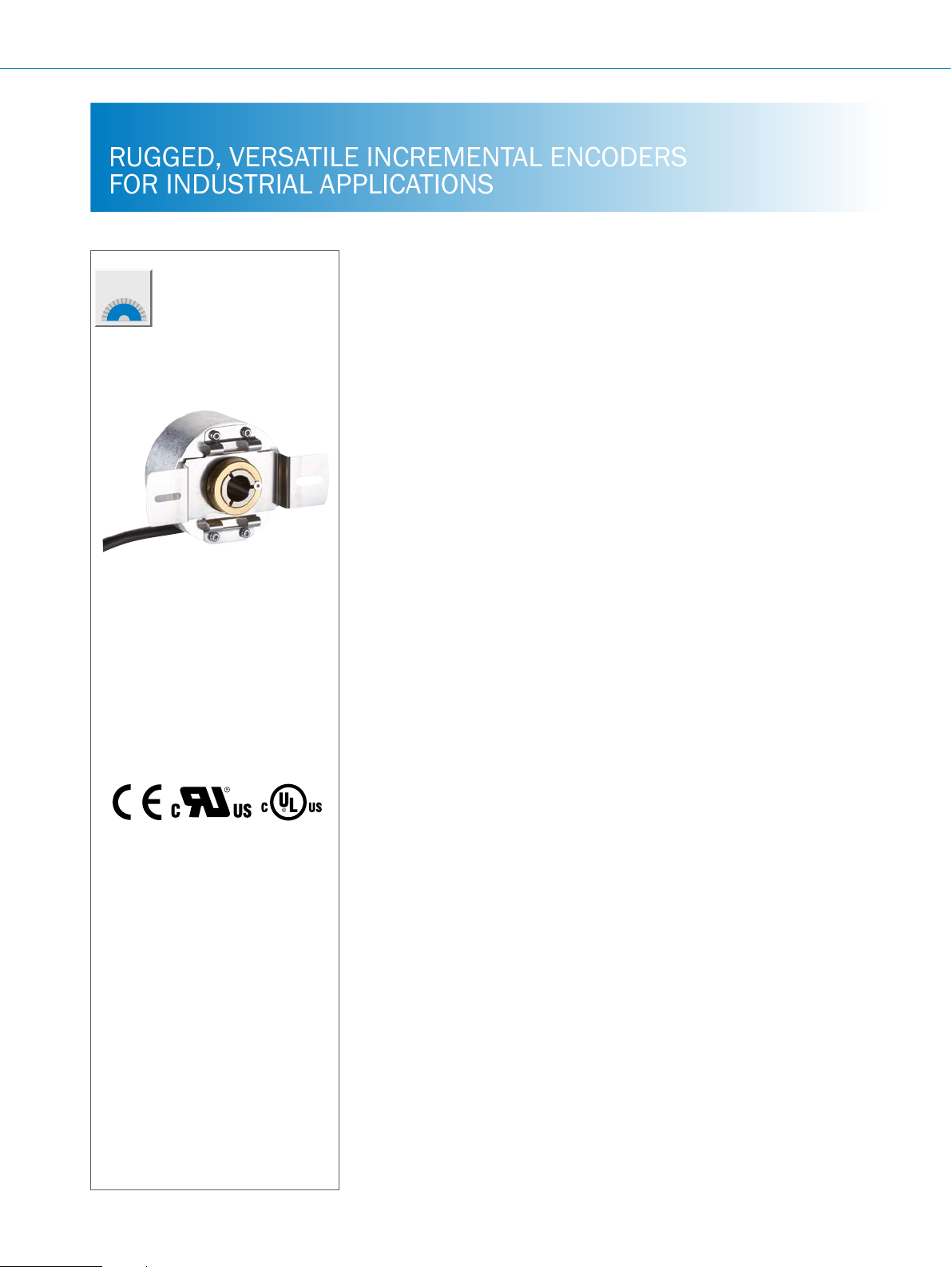
RUGGED, VERSATILE INCREMENTAL ENCODERS
FOR INDUSTRIAL APPLICATIONS
Product description
The DBS60 Core is a rugged incremental
encoder with a 58 mm diameter and
compact installation depth. It offers a
large range of mechanical and electrical
interfaces. The solid shaft models are
available with face mount ange and
servo ange. The hollow shaft design is
available as a blind hollow shaft and as
a through hollow shaft and can receive
shafts up to 5/8" (15.875 mm). The
optional shaft insulation and the shaft
clamping on the back of the encoder are
unique to the hollow shafts. In addition
to the standard interfaces 5 V and 24 V
TTL/RS422 and 24 V HTL/Push-Pull, the
DBS60 Core offers a exible universal
interface which combines the 5 V TTL
and 24 V HTL in one product. The high
enclosure rating IP 65 and the large ball
bearing distance ensure high robustness
and reliability, even in the case of high
shaft loads. With a resolution of up to
5,000 pulses, the DBS60 Core is the
ideal product for standard use in various
different industries.
F
Additional information
Fields of application . . . . . . . . . . .F-121
Detailed technical data. . . . . . . . .F-121
Type code. . . . . . . . . . . . . . . . . . . . F-124
Ordering information. . . . . . . . . . . F-128
Mounting suggestion for servo
ange .......................F-129
Dimensional drawings . . . . . . . . .F-130
Connection type ..............F-153
Viewing number of resolutions. . . F-153
Zero declaration ..............F-154
Signal outputs ................F-154
Recommended accessories. . . . . F-156
At a glance
• Face mount ange, servo ange, blind
and through hollow shaft
• Housing: Ø 58 mm; compact installa-
tion depth, large bearing distance
• Flange and stator couplings enable
diverse mounting options
• Number of lines: up to 5,000 pulses
Your benets
• Diverse installation options due to
different ange and shaft designs
• Universal cable outlet and radial con-
nector allow use in tight spaces and
make exible cable routing possible
• Compact housing dimensions save
valuable space Optional hollow
shaft clamp on the back facilitates
mounting
• Protects the encoder against high
shaft temperatures and currents
through optional isolated shafts
• Cable outlet, radial M23 or M12 male
connector
• TTL/RS-422 and HTL/Push-Pull,
universal interface TTL/HTL with
4.5 V DC to 30 V DC
• Hollow shafts: metal up to Ø 5/8",
isolated up to Ø 15 mm; clamping at
the front and back
• Flanges and stator couplings with
different mounting holes allow diverse
mounting options with one encoder
variant
• Rugged design with large bearing
distance allows high shaft loads and
a longer service life
• The TTL/HTL combination interface
enables less product variety and
reduces storage costs
F-120
ENCODERS | SICK 8015560/2015-09-01
Subject to change without notice
Page 2

Fields of application
Measuring of position, speed and distance in applications with
low to medium requirements on the encoder.
Developed for applications in factory and logistics automation,
e.g., in
Detailed technical data
Performance
Pulses per revolution
Measurement step
Measurement step deviation
< 3,600 pulses per revolution ± 18°/pulses per revolution
≥ 3,600 pulses per revolution ± 36°/pulses per revolution
Error limits
Duty cycle
< 3,600 pulses per revolution ≤ 0.5 ± 5%
≥ 3,600 pulses per revolution ≤ 0.5 ± 10 %
Initialization time
1)
For available pulses per revolution see type code.
2)
After this period valid signals can be read.
4 ... 5,000
90° electrical/pulses per revolution
Measurement step deviation x 3
< 5 ms
1)
2)
INCREMENTAL ENCODERS DBS60 Core
• Asynchronous motors
• Elevators
• Packaging machines
• Warehousing and transport logistics
Mechanical data
Solid shaft Blind hollow shaft Through hollow shaft
Mechanical design
Solid shaft, servo ange
Solid shaft, face mount ange
Shaft diameter
6 mm x 10 mm
10 mm x 19 mm
2)
Mass
Shaft material
Flange material
Housing material
1)
Other on request.
2)
Based on an encoder with a connector outlet or a cable with a connector outlet.
3)
Higher values possible by limiting the overall service life.
4)
Take into account self-heating of 3.2 K per 1000 revolutions/min when designing the working temperature range.
5)
Take into account self-heating of 2.6 K per 1,000 revolutions/min when designing the operating temperature range.
6)
Maximum speed which does not lead to any harm to the encoder. Impact on the service life and signal quality is possible. Please note the maximum output frequency.
0.3 kg
Stainless steel Stainless steel
Aluminum
Aluminum
1)
1)
Blind hollow shaft Through hollow shaft clamping
at the back
Through hollow shaft
6 mm
8 mm
3/8“
10 mm
12 mm
1/2“
14 mm
15 mm
5/8“
6 mm (shaft isolated)
8 mm (shaft isolated)
3/8“ (shaft isolated)
10 mm (shaft isolated)
12 mm (shaft isolated)
1/2“ mm (shaft isolated)
14 mm (shaft isolated)
15 mm (shaft isolated)
2)
0.25 kg
Stainless steel with plastic collar
F
Subject to change without notice
ENCODERS | SICK8015560/2015-09-01
F-121
Page 3

DBS60 Core INCREMENTAL ENCODERS
Solid shaft Blind hollow shaft Through hollow shaft
Cable material
Start up torque
Operating torque
Permissible shaft movement, axial static/
dynamic
Permissible shaft movement, radial
static/dynamic
Permissible shaft load, radial/axial
Operating speed
Maximum operating speed
Rotor moment of inertia
Bearing lifetime
Max. angular acceleration
1)
Other on request.
2)
Based on an encoder with a connector outlet or a cable with a connector outlet.
3)
Higher values possible by limiting the overall service life.
4)
Take into account self-heating of 3.2 K per 1000 revolutions/min when designing the working temperature range.
5)
Take into account self-heating of 2.6 K per 1,000 revolutions/min when designing the operating temperature range.
6)
Maximum speed which does not lead to any harm to the encoder. Impact on the service life and signal quality is possible. Please note the maximum output frequency.
PVC
1.2 Ncm (+20 °C) 0.5 Ncm (+20 °C)
1.1 Ncm (+20 °C) 0.4 Ncm (+20 °C)
– ± 0.5 mm, ± 0.2 mm
– ± 0.3 mm, ± 0.1 mm
100 N (radial)
50 N (axial)
6,000 / min
9,000 /min
3)
3)
4)
6)
–
6,000 / min
5)
33 gcm² 50 gcm²
3.6 x 10^9 revolutions
500,000 rad/s² 500,000 rad/s²
200,000 rad/s² (shaft isolated)
F
Electrical data
Solid shaft Blind hollow shaft Through hollow shaft
Electrical interface
4.5 V ... 5.5 V, TTL/RS422
10 V ... 30 V, TTL/RS422
10 V ... 27 V, HTL/Push Pull
4.5 V ... 30 V, TTL/HTL universal 1)
Connection type
M23 male connector, 12-pin, radial
M12 male connector, 8-pin, radial
Cable, 8-wire, universal, 0.5 m
Cable, 8-wire, universal, 1.5 m
Cable, 8-wire, universal, 3 m
Cable, 8-wire, universal, 5 m
Cable, 8-wire, universal, 10 m
Cable with male connector M12, 8-pin, universal, 0.5 m
Cable with male connector M23, 12-pin, universal, 0.5 m
Operating current without load
4.5 V...5.5 V, TTL/RS422 ≤ 50 mA
Max. power consumption without load
10 V ... 30 V, TTL/RS422 ≤ 0.5 W
10 V ... 27 V, HTL/Push Pull ≤ 1 W
4.5 V ... 30 V, TTL/HTL universal ≤ 0.5 W
Load current
Maximum output frequency
1)
6 channels unless otherwise specied.
2)
Output level depends on the supply voltage.
3)
The universal cable connection is positioned so that it is possible to lay it without bends in a radial or axial direction.
4)
M23 male connector with central mounting
5)
Up to 450 kHz on request.
6)
Short-circuit of another channel or GND permissible for a maximum of 60 s. No protection in the case of a short-circuit channel of US.
7)
Short-circuit of another channel US or GND permissible for a maximum of 30 s.
8)
This product is a standard product and does not constitute a safety component as dened in the Machinery Directive. Calculation based on nominal load of devices, average ambient temperature 40 °C, frequency of use 8760 h/a. All electronic failures are considered hazardous. For more information, see document no.
8015532.
≤ 30 mA per channel
300 kHz
5)
1)
1)
1)
2)
3)
3)
3)
3)
3)
3)
3) 4)
F-122
ENCODERS | SICK 8015560/2015-09-01
Subject to change without notice
Page 4

INCREMENTAL ENCODERS DBS60 Core
Solid shaft Blind hollow shaft Through hollow shaft
Reference signal, number
Reference signal, position
Reverse polarity protection
Short-circuit protection of the outputs
4.5 V–5.5 V, TTL/RS422
10 V ... 30 V, TTL/RS422
10 V ... 27 V, HTL/Push Pull
4.5 V ... 30 V, TTL/HTL universal
MTTFd: mean time to dangerous failure
1)
6 channels unless otherwise specied.
2)
Output level depends on the supply voltage.
3)
The universal cable connection is positioned so that it is possible to lay it without bends in a radial or axial direction.
4)
M23 male connector with central mounting
5)
Up to 450 kHz on request.
6)
Short-circuit of another channel or GND permissible for a maximum of 60 s. No protection in the case of a short-circuit channel of US.
7)
Short-circuit of another channel US or GND permissible for a maximum of 30 s.
8)
This product is a standard product and does not constitute a safety component as dened in the Machinery Directive. Calculation based on nominal load of devices, average ambient temperature 40 °C, frequency of use 8760 h/a. All electronic failures are considered hazardous. For more information, see document no.
8015532.
1
90° electric, logically gated with A and B
l
6)
l
7)
l
7)
l
7)
l
8)
500 years (EN ISO 13849-1)
Ambient data
EMC
Enclosure rating
Permissible relative humidity
Operating temperature range
4.5 V–5.5 V, TTL/RS422 –20 °C ... +85 °C
10 V ... 30 V, TTL/RS422 –30 °C ... +100 °C, at a maximum of 3,000 pulses per revolution
10 V ... 27 V, HTL/Push Pull –20 °C ... +85 °C
4.5 V ... 30 V, TTL/HTL universal –30 °C ... +100 °C, at a maximum of 3,000 pulses per revolution
Storage temperature range
Resistance to shocks
Resistance to vibrations
1)
In an assembled male connector.
Solid shaft Blind hollow shaft Through hollow shaft
According to EN 61000-6-2 and EN 61000-6-3
IP 67 on housing side (acc. to IEC 60529)
1)
IP 65 on shaft side (acc. to IEC 60529)
90% (condensation of optical surfaces not permitted)
–30 °C ... +85 °C, at more than 3,000 pulses per revolution
–30 °C ... +85 °C, at more than 3,000 pulses per revolution
–40 °C ... +100 °C, without packaging
250 g, 3 ms (according to
EN 60068-2-27)
250 g, 3 ms (according to EN 60068-2-27)
200 g, 3 ms, shaft isolated (according to EN 60068-2-27)
30 g/10 Hz ... 2,000 Hz (according to EN 60068-2-6)
IP 65 on housing side (acc. to
IEC 60529)
1)
IP 65 on shaft side (acc. to
IEC 60529)
F
Subject to change without notice
ENCODERS | SICK8015560/2015-09-01
F-123
Page 5
DBS60 Core INCREMENTAL ENCODERS
Type code
Solid shaft
Mechanical design
1 Servo ange, solid shaft, Ø 6 mm, length 10 mm
3 Face mount ange, solid shaft, Ø 6 mm, length 10 mm
4 Face mount ange, solid shaft, Ø 10 mm, length 19 mm
Electrical interface
A 4.5 … 5.5 V, TTL/RS-422, 6 channel
C 10 … 30 V, TTL/RS-422, 6 channel
E 10 … 27 V, HTL/Push Pull, 6 channel
F 4.5 … 30 V, TTL/HTL universal, 6 channel
Connection type
A Male connector M23, 12-pin, radial
C Male connector M12, 8-pin, radial
J Cable, 8-wire universal, 0.5 m
K Cable, 8-wire, universal, 1.5 m
L Cable, 8-wire, universal, 3 m
N Cable, 8-wire, universal, 10 m
P Cable, 8-wire universal, 0.5 m, with male connector M12
Q Cable, 8-wire, universal, 0.5 m, with male connector M23
Stator coupling/ange design
O Flange with 3 x M3 3 x M4
F
D B S 6 0 E - S
1)
Other pulse on request.
Resolution
0004 ... 5,000 pulses per revolution possible. For pulses see “Pulses per revolution”
1)
F-124
ENCODERS | SICK 8015560/2015-09-01
Subject to change without notice
Page 6
Through hollow shaft
Mechanics/ange
T Through hollow shaft
R Through hollow shaft clamping at the back (B side)
Mechanical design
B Through hollow shaft, metal, Ø 8 mm
C Through hollow shaft, metal, Ø 3/8"
D Through hollow shaft, metal, Ø 10 mm
E Through hollow shaft, metal, Ø 12 mm
F Through hollow shaft, metal, Ø 1/2"
G Through hollow shaft, metal, Ø 14 mm
H Through hollow shaft, metal, Ø 15 mm
J Through hollow shaft, metal, Ø 5/8"
2 Through hollow shaft, Ø 8 mm, isolated
3 Through hollow shaft, Ø 3/8", isolated
4 Through hollow shaft, Ø 10 mm, isolated
5 Through hollow shaft, Ø 1/2", isolated
6 Through hollow shaft, Ø 12 mm, isolated
7 Through hollow shaft, Ø 14 mm, isolated
8 Through hollow shaft, Ø 15 mm, isolated
Electrical interface
A 4.5 … 5.5 V, TTL/RS-422, 6 channel
C 10 … 30 V, TTL/RS-422, 6 channel
E 10 … 27 V, HTL/Push Pull, 6 channel
F 4.5 … 30 V, TTL/HTL universal, 6 channel
Connection type
A Male connector M23, 12-pin, radial
C Male connector M12, 8-pin, radial
J Cable, 8-wire, universal, 0.5 m
K Cable, 8-wire, universal, 1.5 m
L Cable, 8-wire, universal, 3 m
N Cable, 8-wire, universal, 10 m
P Cable, 8-wire universal, 0.5 m, with male connector M12
Q Cable, 8-wire, universal, 0.5 m, with male connector M23
Stator coupling/ange design
0 Two-sided stator coupling, slot, screw hole circle 63 mm - 83 mm
A Without stator coupling, ange with 4 x M2.5
C Locating pin assembly
D Stator coupling, 1-sided, slot, bolt circle 33 mm - 48.5 mm
1)
INCREMENTAL ENCODERS DBS60 Core
F
Resolution
0004 ... 5,000 pulses per revolution possible. For pulses see “Pulses per revolution”
D B S 6 0 E -
1)
Order collets for 6 mm (only plastic) 8 mm, 3/8", 10 mm, 12 mm, 1/2", 14 mm and 15 mm separately as accessories (see recommended accessories). No collets are
necessary for 5/8" shaft diameter. Also available as isolated design on request.
Subject to change without notice
ENCODERS | SICK8015560/2015-09-01
F-125
Page 7
DBS60 Core INCREMENTAL ENCODERS
Blind hollow shaft
Mechanical design
B Blind hollow shaft, metal, Ø 8 mm
C Blind hollow shaft, metal, Ø 3/8"
D Blind hollow shaft, metal, Ø 10 mm
E Blind hollow shaft, metal, Ø 12 mm
F Blind hollow shaft, metal, Ø 1/2"
G Blind hollow shaft, metal, Ø 14 mm
H Blind hollow shaft, metal, Ø 15 mm
J Blind hollow shaft, metal, Ø 5/8"
2 Blind hollow shaft, Ø 8 mm, isolated
3 Blind hollow shaft, Ø 3/8", isolated
4 Blind hollow shaft, Ø 10 mm, isolated
5 Blind hollow shaft, Ø 1/2", isolated
6 Blind hollow shaft, Ø 12 mm, isolated
7 Blind hollow shaft, Ø 14 mm, isolated
8 Blind hollow shaft, Ø 15 mm, isolated
Electrical interface
A 4.5 … 5.5 V, TTL/RS-422, 6 channel
C 10 … 30 V, TTL/RS-422, 6 channel
E 10 … 27 V, HTL/Push Pull, 6 channel
F 4.5 … 30 V, TTL/HTL universal, 6 channel
Connection type
A Male connector M23, 12-pin, radial
C Male connector M12, 8-pin, radial
J Cable, 8-wire, universal, 0.5 m
K Cable, 8-wire, universal, 1.5 m
L Cable, 8-wire, universal, 3 m
N Cable, 8-wire, universal, 10 m
P Cable, 8-wire universal, 0.5 m, with male connector M12
Q Cable, 8-wire, universal, 0.5 m, with male connector M23
1)
F
Stator coupling/ange design
0 Two-sided stator coupling, slot, screw hole circle 63 mm - 83 mm
A Without stator coupling, ange with 4 x M2.5
C Locating pin assembly
D Stator coupling, 1-sided, slot, bolt circle 33 mm - 48.5 mm
Resolution
0004 ... 5,000 pulses per revolution possible. For pulses see “Pulses per revolution”
D B S 6 0 E - B
1)
Order collets for 6 mm (only plastic) 8 mm, 3/8", 10 mm, 12 mm, 1/2", 14 mm and 15 mm separately as accessories (see recommended accessories). No collets are
necessary for 5/8" shaft diameter. Also available as isolated design on request.
F-126
ENCODERS | SICK 8015560/2015-09-01
Subject to change without notice
Page 8

Pulses per revolution
Pulses per revolution
INCREMENTAL ENCODERS DBS60 Core
E
0004
0005
0010
0020
0048
0050
0060
0100
0125
0128
0180
0250
0360
0500
0512
0600
1000
1024
1200
1500
2000
2048
2400
2500
3000
3600
4096
5000
F
Subject to change without notice
ENCODERS | SICK8015560/2015-09-01
F-127
Page 9

DBS60 Core INCREMENTAL ENCODERS
Ordering information
Blind hollow shaft
• Shaft diameter: 5/8"
• Connection type: cable, 8-wire, universal, 1.5 m
Through hollow shaft
• Shaft diameter: 5/8"
F
Electrical interface Voltage range Connection type Pulses per
revolution
4.5 V ... 5.5 V
TTL/RS422
10 V ... 30 V
HTL/Push Pull 10 V ... 27 V
TTL/HTL universal 4.5 V ... 30 V
Cable with male con-
nector M23, 12-pin,
universal, 0.5 m
Cable, 8-wire, universal,
1.5 m
Cable, 8-wire, universal,
1.5 m
Cable, 8-wire, universal,
1.5 m
Cable, 8-wire, universal,
1.5 m
1,024 DBS60E-TJAQ01024 1069756
2,048 DBS60E-TJAQ02048 1069757
1,024 DBS60E-TJAK01024 1069746
2,048 DBS60E-TJAK02048 1069747
4,096 DBS60E-TJAK04096 1069748
1,024 DBS60E-TJCK01024 1070615
2,048 DBS60E-TJCK02048 1070616
1,024 DBS60E-TJEK01024 1069758
2,048 DBS60E-TJEK02048 1069759
4,096 DBS60E-TJEK04096 1069760
1,024 DBS60E-TJFK01024 1070748
2,048 DBS60E-TJFK02048 1070749
4,096 DBS60E-TJFK04096 1070750
Type Part no.
Through hollow shaft clamping at the back
• Shaft diameter: 5/8"
• Connection type: cable, 8-wire, universal, 1.5 m
Electrical interface Voltage range Pulses per revolution Type Part no.
1,024 DBS60E-RJAK01024 1069710
4.5 V ... 5.5 V
TTL/RS422
10 V ... 30 V
HTL/Push Pull 10 V ... 27 V
TTL/HTL universal 4.5 V ... 30 V
2,048 DBS60E-RJAK02048 1069711
4,096 DBS60E-RJAK04096 1069712
1,024 DBS60E-RJCK01024 1070609
2,048 DBS60E-RJCK02048 1070610
1,024 DBS60E-RJEK01024 1069713
2,048 DBS60E-RJEK02048 1069714
1,024 DBS60E-RJFK01024 1070744
2,048 DBS60E-RJFK02048 1070745
F-128
ENCODERS | SICK 8015560/2015-09-01
Subject to change without notice
Page 10
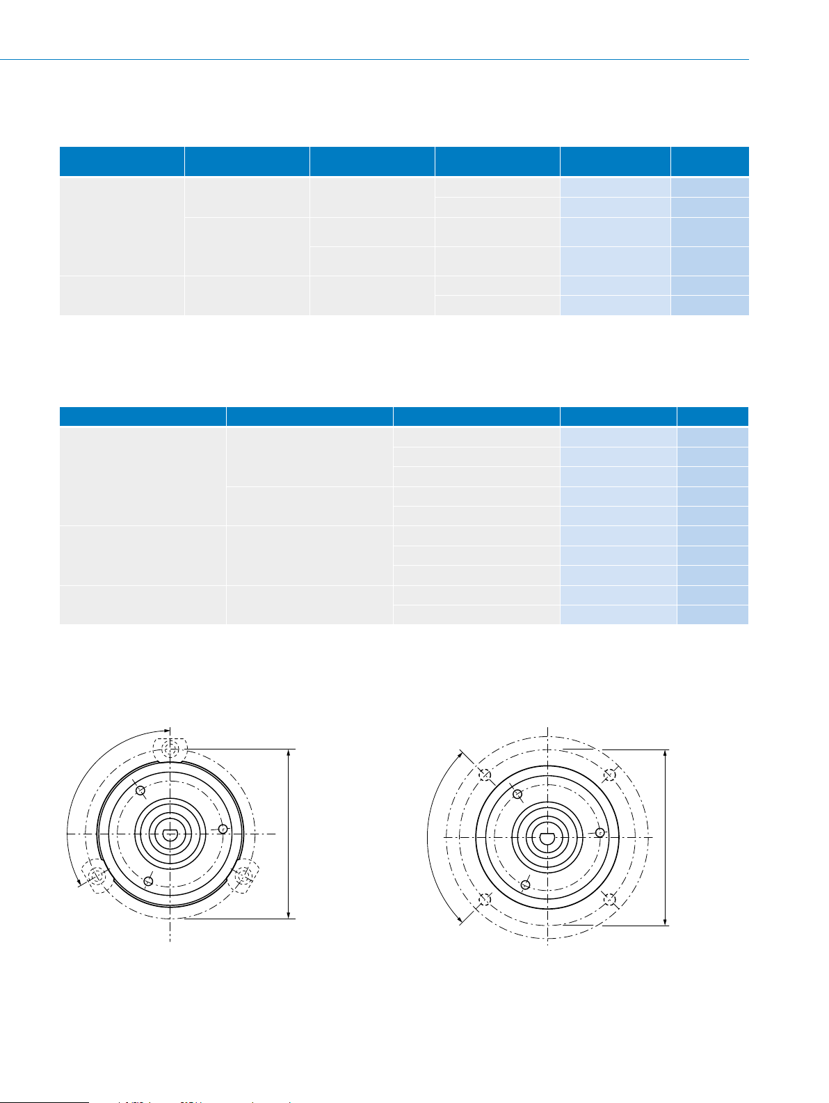
Solid shaft, servo ange
3 x 120°
All dimensions in mm (inch)
4 x 90°
All dimensions in mm (inch)
• Shaft diameter: 6 mm (other diameters available on request)
INCREMENTAL ENCODERS DBS60 Core
Electrical interface Voltage range Connection type Pulses per
revolution
4.5 V ... 5.5 V
TTL/RS422
10 V ... 30 V
HTL/Push Pull 10 V ... 27 V
Cable, 8-wire, universal,
1.5 m
Cable, 8-wire, universal,
1.5 m
Cable, 8-wire, universal,
1.5 m
Cable, 8-wire, universal,
1.5 m
1,000 DBS60E-S1AK01000 1069715
2,000 DBS60E-S1AK02000 1069716
1,000 DBS60E-S1CK01000 1070611
2,000 DBS60E-S1CK02000 1070612
1,000 DBS60E-S1EK01000 1069717
2,000 DBS60E-S1EK02000 1069718
Type Part no.
Solid shaft, face mount ange
• Shaft diameter: 10 mm (other diameters available on request)
• Connection type: cable, 8-wire, universal, 1.5 m
Electrical interface Voltage range Pulses per revolution Type Part no.
1,000 DBS60E-S4AK01000 1069719
4.5 V ... 5.5 V
TTL/RS422
10 V ... 30 V
HTL/Push Pull 10 V ... 27 V
TTL/HTL universal 4.5 V ... 30 V
2,000 DBS60E-S4AK02000 1069720
5,000 DBS60E-S4AK05000 1069721
1,000 DBS60E-S4CK01000 1070613
2,000 DBS60E-S4CK02000 1070614
1,000 DBS60E-S4EK01000 1069722
2,000 DBS60E-S4EK02000 1069723
5,000 DBS60E-S4EK05000 1069724
1,000 DBS60E-S4FK01000 1070746
2,000 DBS60E-S4FK02000 1070747
F
Mounting suggestion for servo ange
Mounting suggestion for small servo clamp (part number
2029166)
Ø 68 (2.68)
Subject to change without notice
Mounting suggestion for half-shell servo clamp (part number
2029165)
Ø 71 (2.80)
ENCODERS | SICK8015560/2015-09-01
F-129
Page 11
DBS60 Core INCREMENTAL ENCODERS
(0.28)
on housing
3 x M3 - depth 7
Dimensional drawings (dimensions in mm)
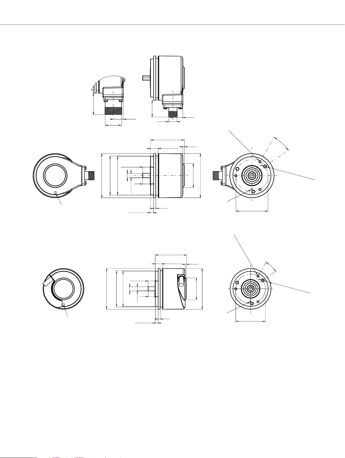
Solid shaft Ø 6 mm, servo ange, male connector connection (S1)
28.3
(1.11)
M23
13
(0.51)
22
(0.87)
M12
13
(0.51)
3 x M3 - depth 7
F
10 ±0.3
(0.39 ±0.01)
(0.24)
Ø 6 f7
9.5
(0.37)
5.7
(0.22)
4 +0.1
(0.16 +0.01)
Zero pulse mark
on housing
Ø 58 ±0.1 (2.28 ±0.01)
Ø 51.5 -0.2 (2.03 -0.01)
Ø 50 f8 (1.97)
Solid shaft Ø 6 mm, servo ange, cable connection
10 ±0.3
(0.39 ±0.01)
(2.03 -0.01)
Ø 51.5 -0.2
Ø 50 f8 (1.97)
Ø 6 f7 (0.24)
5.7
(0.22)
Ø 58 ±0.1
(2.28 ±0.01)
9.5
(0.37)
44.35
(1.75)
10 +0.1
(0.39 +0.01)
3
(0.12)
44.35
(1.75)
10 +0.1
(0.39 +0.01)
2
(0.08)
(0.08)
31.4 (1.24)
2
31.4 (1.24)
Ø 58 (2.28)
Zero pulse mark
on flange
Ø 58 (2.28)
3 x 120°
Ø 42 ±0.05
(1.65 ±0.01)
3 x 120°
(0.28)
(0.28)
25°
3 x M4 - depth 7
25°
3 x M4 - depth 7
3 x 120°
3 x 120°
(0.28)
F-130
3
Zero pulse mark
ENCODERS | SICK 8015560/2015-09-01
4 +0.1
(0.16 +0.01)
(0.12)
Zero pulse mark
on flange
Ø 42 ±0.05
(1.65 ±0.01)
Subject to change without notice
Page 12
Solid shaft Ø 10 mm, face mount ange, male connector connection (S4)
28.3
(1.11)
M23
19 ±0.3
(0.75 ±0.01)
Ø 36 f8
Ø 10 f7
9
13
(0.51)
(0.35)
18
(0.71)
22
10
(0.39)
(0.87)
M12
44.35
(1.75)
2
(0.08)
13
(0.51)
INCREMENTAL ENCODERS DBS60 Core
3 x M4 - depth 6
3 x 120°
31.4 (1.24)
Ø 58 (2.28)
(0.24)
20°
3 x M3 - depth 6
3 x 120°
(0.24)
Zero pulse mark
on housing
Solid shaft Ø 6 mm, face mount ange, male connector connection (S3)
28.3
(1.11)
M23
(1.42)
Ø 36 f8
13
(0.51)
(0.24)
Ø 6 f7
5.7
9.5
(0.37)
(0.22)
10
(0.39)
0.8
(0.03)
10 ±0.3
(0.39)
22
(0.87)
M12
44.35
(1.75)
13
(0.51)
(0.08)
2
31.41
(1.24)
Ø 58
(2.28)
Zero pulse mark
on flange
3x M4 - depth 6 mm
3x 120°
(0.24)
Ø 48 ±0.05
(1.89 ±0.01)
20°
3x M3 - depth 6 mm
3x 120°
F
(0.24)
Zero pulse mark
on housing
Subject to change without notice
Ø 48 ±0.05
(1.89)
Zero pulse mark
on flange
ENCODERS | SICK8015560/2015-09-01
F-131
Page 13
DBS60 Core INCREMENTAL ENCODERS
3 x M4 - dept
3x M4 - depth 6 mm
on housing
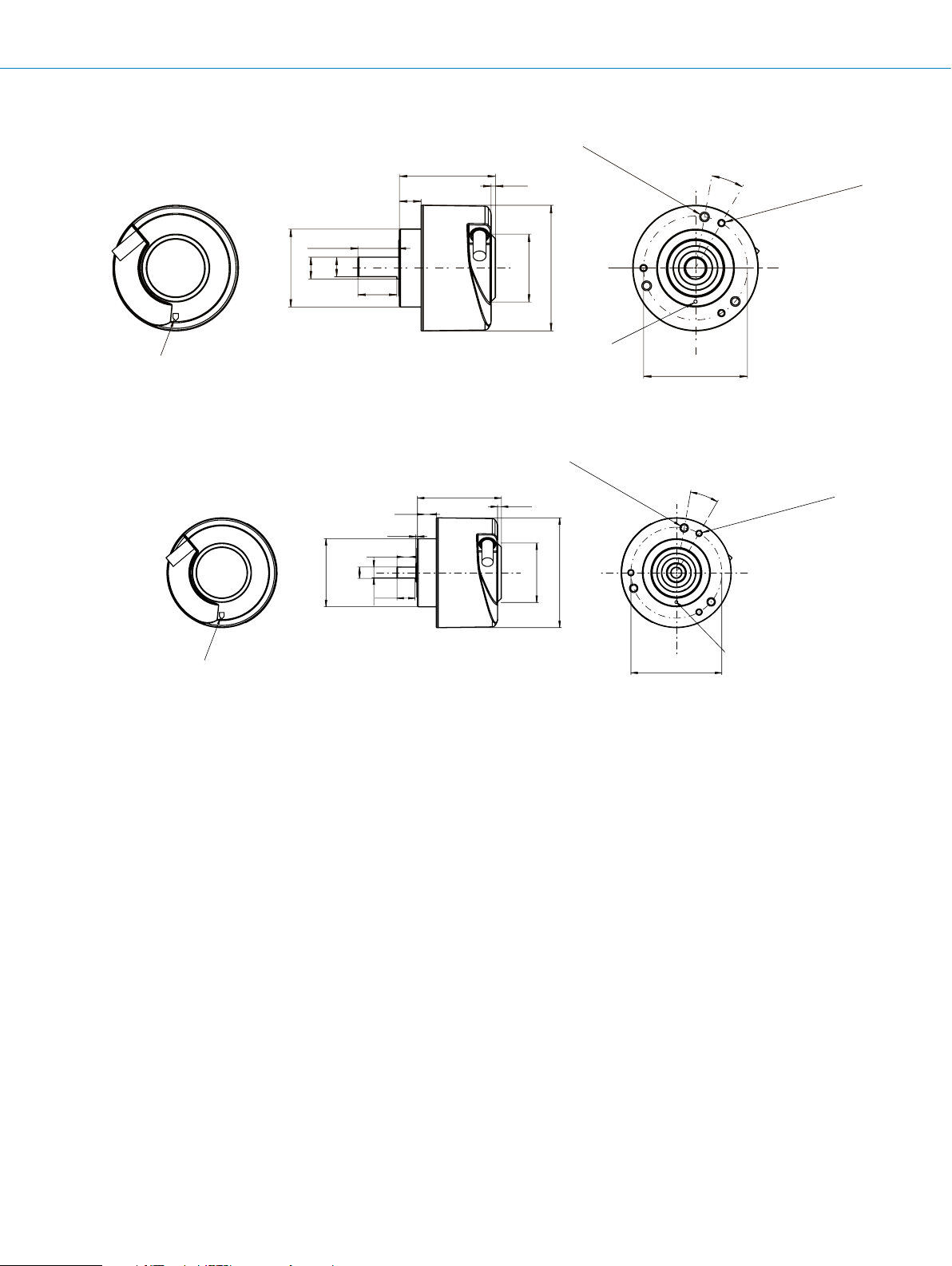
Solid shaft Ø 10 mm, face mount ange, cable connection (S4)
44.35
(1.75)
10
(0.39)
19 ±0.3
(0.75 ±0.01)
9
Ø 10 f7
(0.35)
18
(0.71)
Zero pulse mark
on housing
Ø 36 f8
Solid shaft Ø 6 mm, face mount ange, cable connection (S3)
44.35
(1.75)
(1.42)
Ø 36 f8
(0.24)
Ø 6 f7
10 ±0.3
(0.39)
(0.37)
5.7
(0.22)
9.5
(0.39)
0.8
(0.03)
10
2
(0.08)
(0.08)
2
(1.24)
31.4
31.4
(1.24)
(2.28)
Ø 58
Zero pulse mark
on flange
Ø 58
(2.28)
3 x 120°
3x 120°
h 6
(0.24)
(0.24)
Ø 48 ±0.05
(1.89 ±0.01)
20°
20°
3 x M3 - depth 6
3 x 120°
3x M3 - depth 6 mm
3x 120°
(0.24)
(0.24)
F
Zero pulse mark
Ø 48 ±0.05
(1.89)
Zero pulse mark
on flange
F-132
ENCODERS | SICK 8015560/2015-09-01
Subject to change without notice
Page 14

INCREMENTAL ENCODERS DBS60 Core
Without stator coupling
on flange
Blind hollow shaft, male connector connection, two-sided stator coupling, slot, screw hole circle 63 mm – 83 mm
28,3
(1.11)
M23
13
(0.51)
9.4
(0.37)
22
(0.87)
M12
43.8
(1.72)
13
(0.51)
(0.08)
3.2 +0.1
(0.13 +0.01)
2
Ø X F7
50 (1.97)
Zero pulse mark
on housing
Blind hollow shaft, male connector connection, no stator coupling
28.3
(1.11)
13
(0.51)
M23
22
(0.87)
M12
(2.28)
Ø 58
31.41 (1.24)
Zero pulse mark on flange
under stator coupling
13
(0.51)
4 x M2.5 - depth 5
(0.20)
25
(0.98)
63 (2.48)
(3.27)
83
94 (3.70)
F
Zero pulse mark
on housing
Subject to change without notice
42.9
(1.69)
37.6°
Zero pulse mark
ENCODERS | SICK8015560/2015-09-01
37.6°
Ø 49.65 (1.95)
F-133
Page 15

DBS60 Core INCREMENTAL ENCODERS
3.5
Zer
on housing
,
Customer-side
Blind hollow shaft, male connector connection, with locating pin assembly
(0.14)
28.3
(1.11)
M23
5.2 (0.20) (slot depth)
13
(0.51)
22
(0.87)
M12
42.9 (1.69)
41.4 (1.63)
7 (0.28)
13
(0.51)
2 (0.08)
37.6°
120°
3.4
(0.13)
Rubber insert
material: NBR
F
o pulse mark
Removable pin
Installation example for blind hollow shaft
min. 15
(0.59)
max. 40
(1.57)
Ø X F7
15 (0.59)
-0.006
Ø 4 fg 6 -0.014
-0.001
(0.16 fg 0.24 )
-0.001
(1.24)
31.41
Ø 58
(2.28)
37.6°
6 x Ø 2.9 (0.11) - depth
Ø 5↓4
(0.20) (0.16)
Pin is the
zero pulse mark
Ø 49.65
(1.95)
150°
18.9
(0.74)
F-134
ENCODERS | SICK 8015560/2015-09-01
Subject to change without notice
Page 16

INCREMENTAL ENCODERS DBS60 Core
under stator coupling
Customer-side
Blind hollow shaft, male connector connection, stator coupling, 1-sided, slot, bolt circle 33 mm – 48.5 mm
28.3
(1.11)
M23
Zero pulse mark
on housing
Installation example for blind hollow shaft
min. 15
(0.59)
max. 40
(1.57)
22
(0.87)
13
(0.51)
83
26.7
(3.27)
Ø X F7
(1.05)
M12
9.4 (0.37)
43.8
(1.72)
13
(0.51)
31.41
2 (0.08)
(1.24)
Ø 58
(2.28)
54 (2.13)
(1.91)
48.5
31.5 (1.24)
5.1 (0.20)
Zero pulse mark on flange
25
(0.98)
37.6°
37.6°
37.6°
F
Subject to change without notice
ENCODERS | SICK8015560/2015-09-01
F-135
Page 17

DBS60 Core INCREMENTAL ENCODERS
3.2 +0.1
Customer-side
Without stator coupling
4 x M2.5 - depth 5
Customer-side
Blind hollow shaft, cable connection, two-sided stator coupling, slot, screw hole circle 63 mm – 83 mm
Zero pulse mark
on housing
Installation example for blind hollow shaft
min. 15
(0.59)
max. 40
(1.57)
43.8
9.4
(0.37)
50
(1.97)
Ø X F7
(1.72)
2
(0.08)
(2.28)
Ø 58
31.41 (1.24)
Zero pulse mark on flange
under stator coupling
(0.13 +0.01)
25
(0.98)
63 (2.48)
83 (3.27)
94 (3.70)
F
Blind hollow shaft, cable connection, no stator coupling
Zero pulse mark
on housing
Installation example for blind hollow shaft
min. 15
(0.59)
max. 40
(1.57)
42.9
(1.69)
(0.20)
37.6°
37.6°
Zero pulse mark
on flange
(1.95)
Ø 49.65
F-136
ENCODERS | SICK 8015560/2015-09-01
Subject to change without notice
Page 18

Blind hollow shaft, cable connection, with locating pin assembly
3.5
Zer
on housing
,
erial: NBR
Customer-side
(0.14)
42.9 (1.69)
41.4 (1.63)
o pulse mark
5.2 (0.20) (slot depth)
Ø X F7
Removable pin
15 (0.59)
7 (0.28)
Ø 4 fg 6 -0.014
(0.16 fg 0.24 )
-0.006
-0.001
-0.001
2 (0.08)
(1.24)
31.41
INCREMENTAL ENCODERS DBS60 Core
Ø 58
(2.28)
6 x Ø 2.9 (0.11) - depth
37.6°
Ø 5↓4
(0.20) (0.16)
120°
37.6°
Pin is the
zero pulse mark
3.4
(0.13)
Ø 49.65
(1.95)
Rubber insert
mat
150°
18.9
(0.74)
Installation example for blind hollow shaft
min. 15
(0.59)
max. 40
(1.57)
F
Subject to change without notice
ENCODERS | SICK8015560/2015-09-01
F-137
Page 19

DBS60 Core INCREMENTAL ENCODERS
2 (0.08)
under stator coupling
Customer-side
Blind hollow shaft, cable connection, stator coupling, 1-sided, slot, bolt circle 33 mm – 48.5 mm
Ø X F7
Ø 58
(2.28)
(1.24)
31.41
83
26.7
(3.27)
Zero pulse mark
on housing
Installation example for blind hollow shaft
(1.05)
9.4 (0.37)
43.8
(1.72)
(2.13)
54
31.5 (1.24)
48.5 (1.91)
5.1 (0.20)
25
(0.98)
37.6°
37.6°
37.6°
Zero pulse mark on flange
F
min. 15
(0.59)
max. 40
(1.57)
F-138
ENCODERS | SICK 8015560/2015-09-01
Subject to change without notice
Page 20

INCREMENTAL ENCODERS DBS60 Core
6.8
(0.27)
Customer-side
Through hollow shaft clamping at the back, male connector connection, two-sided stator coupling, slot, screw hole circle
63 mm – 83 mm
28.3
(1.11)
M23
13
(0.51)
22
(0.87)
M12
13
(0.51)
Zero pulse mark
on housing
Installation example for through hollow shaft
min. 54
(2.13)
9.4
(0.37)
50
(1.97)
48.6
(1.91)
(0.98)
Ø 25
Ø 58 (2.28)
Ø X F7
Zero pulse mark on flange
under stator coupling
3.2 +0.1
(0.13 +0.01)
25
(0.98)
63 (2.48)
83 (3.27)
94 (3.70)
F
Subject to change without notice
ENCODERS | SICK8015560/2015-09-01
F-139
Page 21

DBS60 Core INCREMENTAL ENCODERS
on housing
Customer-side
Through hollow shaft clamping at the back, male connector connection, no stator coupling
28,3
(1.11)
22
Zero pulse mark
M23
13
(0.51)
(0.87)
M12
Ø X F7
13
(0.51)
Ø 58
Ø 25
37,6°
Without stator coupling
4 x M2,5 - tiefe 5
(0.20)
83
Zero pulse mark
on flange
37,6°
Ø 49,65 (1.95)
F
Installation example for through hollow shaft
min. 54
(2.13)
F-140
ENCODERS | SICK 8015560/2015-09-01
Subject to change without notice
Page 22

INCREMENTAL ENCODERS DBS60 Core
zero pulse mark
Customer-side
Through hollow shaft clamping at the back, male connector connection, with locating pin assembly
3.5
(0.14)
28.3
(1.11)
M23
13
(0.51)
22
(0.87)
M12
13
(0.51)
46.2 (1.82)
39.4 (1.55)
15 (0.59)
7 (0.28)
Ø 4 fg 6 -0.014
(0.16 fg 0.24 )
5.2 (0.20) (slot depth)
Zero pulse mark
on housing
Removable pin
Installation example for through hollow shaft
min. 54
(2.13)
-0.006
-0.001
-0.001
6.8 (0.27)
Ø 25
Ø X F7
Ø 58
(2.28)
(0.98)
6 x Ø 2.9 (0.11) - depth
37.6°
Ø 5↓4
(0.20) (0.16)
120°
37.6°
Pin is the
3.4
(0.13)
Ø 49.65
(1.95)
150°
18.9
(0.74)
Rubber insert,
material: NBR
F
Subject to change without notice
ENCODERS | SICK8015560/2015-09-01
F-141
Page 23

DBS60 Core INCREMENTAL ENCODERS
under stator coupling
Customer-side
Through hollow shaft clamping at the back, male connector connection, one-sided stator coupling, slot, screw hole cir-
cle 33 mm – 48.5 mm
F
28.3
(1.11)
M23
Zero pulse mark
on housing
Installation example for through hollow shaft
min. 54
(2.13)
22
(0.87)
13
(0.51)
83
(3.27)
26.7
(1.05)
M12
9.4 (0.37)
48.6
(1.91)
13
(0.51)
Ø 25
Ø X F7
(0.98)
Ø 58
(2.28)
54 (2.13)
(1.24)
48.5 (1.91)
31.5
5.1 (0.20)
Zero pulse mark on flange
25
(0.98)
37.6°
37.6°
37.6°
F-142
ENCODERS | SICK 8015560/2015-09-01
Subject to change without notice
Page 24

INCREMENTAL ENCODERS DBS60 Core
Customer-side
Zer
on housing
4 x M2.5 - depht
Customer-side
Through hollow shaft clamping at the back, cable connection, two-sided stator coupling, slot, screw hole circle 63 mm – 83 mm
48.6
(1.91)
Zero pulse mark
on housing
Installation example for through hollow shaft
min. 54
(2.13)
9.4
(0.37)
50 (1.97)
6.8
(0.27)
(2.28)
Ø 25 (0.98)
Ø 58
Ø X F7
Zero pulse mark on flange
under stator coupling
3.2 +0.1
(0.13 +0.01)
25
(0.98)
63 (2.48)
83 (3.27)
94 (3.70)
Through hollow shaft clamping at the back, cable connection, no stator coupling
37.6°
o pulse mark
Without stator coupling
Installation example for through hollow shaft
min. 54
(2.13)
(0.20)
F
5
(1.95)
37.6°
Ø 49.65
Zero pulse mark
on flange
Subject to change without notice
ENCODERS | SICK8015560/2015-09-01
F-143
Page 25

DBS60 Core INCREMENTAL ENCODERS
3.5
Zer
on housing
,
Customer-side
Through hollow shaft clamping at the back, cable connection, with locating pin assembly
(0.14)
F
5.2 (0.20) (slot depth)
o pulse mark
15 (0.59)
Removable pin
Installation example for through hollow shaft
min. 54
(2.13)
46.2 (1.82)
39.4 (1.55)
7 (0.28)
-0.006
Ø 4 fg 6 -0.014
(0.16 fg 0.24 )
-0.001
-0.001
6.8 (0.27)
Ø 25
Ø X F7
(0.98)
Ø 58
(2.28)
37.6°
6 x Ø 2.9 (0.11) - depth
Ø 5↓4
(0.20) (0.16)
120°
37.6°
Pin is the
zero pulse mark
3.4
(0.13)
Ø 49.65
(1.95)
Rubber insert
material: NBR
150°
18.9
(0.74)
F-144
ENCODERS | SICK 8015560/2015-09-01
Subject to change without notice
Page 26

INCREMENTAL ENCODERS DBS60 Core
Customer-side
Through hollow shaft clamping at the back, cable connection, one-sided stator coupling, slot, screw hole circle 33 mm – 48.5 mm
37.6°
25
Ø 58
(0.98)
Zero pulse mark
on housing
(2.28)
83
(3.27)
26.7
(1.05)
9.4 (0.37)
48.6
(1.91)
Ø X F7
6.8 (0.27)
(2.13)
54
48.5 (1.91)
31.5 (1.24)
5.1 (0.20)
Zero pulse mark on flange
25
(0.98)
under stator coupling
37.6°
37.6°
Installation example for through hollow shaft
min. 54
(2.13)
F
Subject to change without notice
ENCODERS | SICK8015560/2015-09-01
F-145
Page 27

DBS60 Core INCREMENTAL ENCODERS
Customer-side
Through hollow shaft clamping at the front, male connector connection, two-sided stator coupling, slot, screw hole circle
63 mm – 83 mm
F
28.3
(1.11)
M23
Zero pulse mark
on housing
Installation example for through hollow shaft
min. 15
(0.59)
13
(0.51)
9.4
(0.37)
50 (1.97)
22
(0.87)
Ø X F7
M12
41.8
(1.65)
13
(0.51)
Ø 58 (2.28)
Zero pulse mark on flange
under stator coupling
3.2 +0.1
(0.13 +0.01)
25
(0.98)
63 (2.48)
(3.27)
83
(3.70)
94
F-146
ENCODERS | SICK 8015560/2015-09-01
Subject to change without notice
Page 28

INCREMENTAL ENCODERS DBS60 Core
on housing
Customer-side
Through hollow shaft clamping at the front, male connector connection, no stator coupling
Zero pulse mark
Installation example for through hollow shaft
min. 15
(0.59)
28.3
(1.11)
M23
(0.51)
40.9
(1.61)
22
(0.87)
13
M12
Without stator coupling
(0.51)
4 x M2.5 - depth 5
(0.20)
37.6°
13
(1.95)
37.6°
Ø 49.65
Zero pulse mark
on flange
F
Subject to change without notice
ENCODERS | SICK8015560/2015-09-01
F-147
Page 29

DBS60 Core INCREMENTAL ENCODERS
3.5
Zer
on housing
,
Customer-side
Through hollow shaft, male connector connection, with locating pin assembly
(0.14)
28.3
(1.11)
M23
5.2 (0.20) (slot depth)
o pulse mark
Removable pin
13
(0.51)
22
Ø X F7
15 (0.59)
(0.87)
M12
40.9 (1.61)
39.4 (1.55)
7 (0.28)
Ø 4 fg 6 -0.014
(0.16 fg 0.24 )
-0.006
-0.001
-0.001
13
(0.51)
Ø 58
(2.28)
6 x Ø 2.9 (0.11) - depth
37.6°
Ø 5↓4
(0.20) (0.16)
Pin is the
zero pulse mark
37.6°
120°
3.4
(0.13)
Ø 49.65
(1.95)
Rubber insert
material: NBR
150°
18.9
(0.74)
F
Installation example for through hollow shaft
min. 15
(0.59)
F-148
ENCODERS | SICK 8015560/2015-09-01
Subject to change without notice
Page 30

INCREMENTAL ENCODERS DBS60 Core
under stator coupling
Customer-side
Through hollow shaft, male connector connection, stator coupling, 1-sided, slot, bolt circle 33 mm – 48.5 mm
28.3
(1.11)
M23
Zero pulse mark
on housing
Installation example for through hollow shaft
min. 15
(0.59)
83
(0.51)
(3.27)
13
26.7
(1.05)
22
(0.87)
Ø X F7
M12
9.4 (0.37)
41.8
(1.65)
13
(0.51)
Ø 58
(2.28)
54 (2.13)
48.5 (1.91)
31.5 (1.24)
5.1 (0.20)
Zero pulse mark on flange
25
(0.98)
37.6°
37.6°
37.6°
F
Subject to change without notice
ENCODERS | SICK8015560/2015-09-01
F-149
Page 31

DBS60 Core INCREMENTAL ENCODERS
3.2 +0.1
Zer
on housing
41.8
Customer-side
Zer
on housing
Customer-side
Through hollow shaft clamping at the front, cable connection, two-sided stator coupling, slot, screw hole circle 63 mm – 83 mm
50
(1.97)
o pulse mark
Installation example for through hollow shaft
min. 15
(0.59)
9.4
(0.37)
Ø X F7
(1.65)
Ø X F7
Ø 58
(2.28)
Zero pulse mark
on flange under
stator coupling
(0.13 +0.01)
25 (0.98)
63 (2.48)
83 (3.27)
94 (3.70)
F
Through hollow shaft clamping at the front, cable connection, no stator coupling
4 x M2.5 - depth 5 (0.20)
o pulse mark
40.9
(1.61)
Without stator coupling
Installation example for through hollow shaft
min. 15
(0.59)
37.6°
(1.95)
37.6°
Ø 49.65
Zero pulse mark
on flange
F-150
ENCODERS | SICK 8015560/2015-09-01
Subject to change without notice
Page 32

Through hollow shaft, cable connection, with locating pin assembly
3.5
Zer
on housing
,
Customer-side
(0.14)
40.9
(1.61)
39.4 (1.55)
15 (0.59)
7 (0.28)
-0.006
Ø 4 fg 6 -0.014
-0.001
(0.16 fg 0.24 )
-0.001
Ø 58
(2.28)
5.2 (0.20) (slot depth)
Ø X F7
o pulse mark
Removable pin
INCREMENTAL ENCODERS DBS60 Core
37.6°
6 x Ø 2.9 (0.11) - depth
Ø 5↓4
(0.20) (0.16)
120°
37.6°
Pin is the
zero pulse mark
3.4
(0.13)
Ø 49.65
(1.95)
Rubber insert
material: NBR
150°
18.9
(0.74)
Installation example for through hollow shaft
min. 15
(0.59)
F
Subject to change without notice
ENCODERS | SICK8015560/2015-09-01
F-151
Page 33

DBS60 Core INCREMENTAL ENCODERS
Customer-side
Through hollow shaft, cable connection, stator coupling, 1-sided, slot, bolt circle 33 mm – 48.5 mm
Ø X F7
Ø 58
(2.28)
83
(3.27)
26.7
Zero pulse mark
on housing
(1.05)
9.4 (0.37)
(2.13)
54
31.5 (1.24)
48.5 (1.91)
37.6°
37.6°
37.6°
F
Installation example for through hollow shaft
min. 15
(0.59)
5.1 (0.20)
Zero pulse mark on flange
25
(0.98)
under stator coupling
F-152
ENCODERS | SICK 8015560/2015-09-01
Subject to change without notice
Page 34

INCREMENTAL ENCODERS DBS60 Core
8-core cable
5.120
4.096
3.072
2.048
1.024
Pulses/Revolution
Speed N [min
]
9.000
Connection type
View of M12 device connector on View of M23 device connector on cable
cable/housing cable/housing
Colour of wires Pin 12-pole in
Brown1 6 Not connectedA- Signal line
White2 5AA Signal line
Black 31Not connectedB- Signal line
Pink 48BB Signal line
Yellow5 4 Not connectedZ- Signal line
Lilac 6 3 ZZ Signal line
Blue 7 10 GND GND
Red8 12 +Us+Us Supply voltage
--9Not connected Not connected Not connected
--2Not connected Not connected Not connected
--11 Not connected Not connected Not connected
--7Not connected Not connected Not connected
Screen Screen Screen Screen Screen
Viewing number of resolutions
M12
Pin 12-pole in
M23
Signal OC Signal TTL; HTL Explanation
Ground connection
of the Encoder
Screen (Screen
connected to
Encoder housing.
F
Subject to change without notice
0
0
2.0001.000 3.000 4.000 5.000 6.000 8.0007.000
–1
ENCODERS | SICK8015560/2015-09-01
F-153
Page 35

DBS60 Core INCREMENTAL ENCODERS
housing mark
housing mark
use shaf
zer
k
Zero declaration
Hollow shaft, clamping at front
Zero pulse mark on flange
Attention!
Zero pulse is active when
screw of clamping is in
line with zero pulse
mark on flange or
Hollow shaft, clamping at back
If stator coupling is mounted,
the zero pulse mark can be
hidden by the stator coupling
F
Solid shaft
t flat for zero mark alignment with
o mark on flange or housing
Zero pulse is active when
screw of clamping is in
line with zero pulse
mark on flange or
Zero pulse mar
on flange
F-154
ENCODERS | SICK 8015560/2015-09-01
Subject to change without notice
Page 36

Signal outputs
Signal outputs for electrical interfaces TTL and HTL
INCREMENTAL ENCODERS DBS60 Core
Supply voltage Output
4.5 ... 5.5 V TTL
10 ... 30 V TTL
10 ... 27 V HTL
4.5 ... 30 V TTL/HTL universal
CW with view on the encoder shaft in direction “A”, compare dimensional drawing.
F
Subject to change without notice
ENCODERS | SICK8015560/2015-09-01
F-155
Page 37

DBS60 Core INCREMENTAL ENCODERS
Recommended accessories
Mounting systems
Mounting brackets and plates
Mounting bracket
Figure Brief description Type Part no.
F
Mounting bracket for encoder with centering hub 36 mm, including mounting kit for face
mount ange
BEF-WF-36 2029164
Flanges
Flange plate
Figure Brief description Type Part no.
Two-sided stator coupling, screw hole circle diameter 63 mm, slot width 3.2 mm BEF-DS-09 2076214
Two-sided stator coupling, slot, slot radius 63 mm – 83 mm, slot width 3.2 mm BEF-DS-10 2076215
One-sided stator coupling, slots, slot radius 32.75 mm – 142.65 mm, slot width 4.5 mm BEF-DS-11 2076216
One-sided stator coupling, slot, slot radius 33 mm – 48.5 mm, slot width 5.1 mm BEF-DS-12 2076217
Flange adapter (for hollow shaft) for locating pin assembly (PIN 4 mm) BEF-DS-13 2076218
One-sided stator coupling, slot, slot radius 32.1 mm – 37.6 mm, slot width 4.5 mm BEF-DS-14 2076678
Flange adapter, adaptation of face mount ange with 36 mm centering hub to 50 mm
servo ange, aluminum, including 3 at head screws M4 x 10
Flange adapter, adaptation of face mount ange with 36 mm centering hub to 60 mm
square mounting plate, aluminum, including 3 at head screws M4 x 10
Flange adapter, adaptation of face mount ange with 36 mm centering hub to 58 mm
square mounting plate with shock absorbers, aluminum
Flange adapter, adaptation of face mount ange with 36 mm centering hub to 63 mm
square mounting plate, aluminum, including 3 at head screws M4 x 10
BEF-FA-036-050 2029160
BEF-FA-036-060REC 2029162
BEF-FA-036-060RSA 2029163
BEF-FA-036-063REC 2034225
F-156
ENCODERS | SICK 8015560/2015-09-01
Subject to change without notice
Page 38

INCREMENTAL ENCODERS DBS60 Core
Other mounting accessories
Measuring wheels and measuring wheel systems
Figure Brief description Type Part no.
Measuring wheel with smooth plastic surface (Hytrel) for 10 mm solid shaft, circumference 200 mm
Measuring wheel with ridged plastic surface (Hytrel) for 10 mm solid shaft, circumference 200 mm
Measuring wheel with smooth plastic surface (Hytrel) for 10 mm solid shaft, circumference 500 mm
Measuring wheel with O-ring (NBR70) for 6 mm solid shaft, circumference 200 mm BEF-MR006020R 2055222
Measuring wheel with O-ring (NBR70) for 6 mm solid shaft, circumference 300 mm BEF-MR006030R 2055634
Measuring wheel with O-ring (NBR70) for 6 mm solid shaft, circumference 500 mm BEF-MR006050R 2055225
Measuring wheel with O-ring (NBR70) for 10 mm solid shaft, circumference 200 mm BEF-MR010020R 2055224
Measuring wheel with O-ring (NBR70) for 10 mm solid shaft, circumference 300 mm BEF-MR010030R 2049278
Measuring wheel with O-ring (NBR70) for 10 mm solid shaft, circumference 500 mm BEF-MR010050R 2055227
O-ring for measuring wheels (circumference 200 mm) BEF-OR-053-040 2064061
O-ring for measuring wheels (circumference 300 mm) BEF-OR-083-050 2064076
O-ring for measuring wheels (circumference 500 mm) BEF-OR-145-050 2064074
BEF-MR-010020 5312988
BEF-MR-010020G 5318678
BEF-MR-010050 5312989
Mounting bell
Figure Brief description Type Part no.
Mounting bell for encoders with a servo ange, centering hub 50 mm, including mounting kit
BEF-MG-50 5312987
F
Servo clamps
Figure Brief description Type Part no.
Half-shell servo clamps (2 pcs.) for servo anges with a 50 mm centering hub BEF-WG-SF050 2029165
Servo clamps, large, for servo anges (clamps, eccentric fastener), 3 pcs., without
mounting material
BEF-WK-SF 2029166
Shaft adaptation
Collets and clamping rings
Figure Brief description Type Part no.
Metal collet for hollow shaft, shaft diameter 8 mm, outer diameter 5/8" (15.875 mm),
metal
Metal collet for hollow shaft, shaft diameter 3/8 " (9.525 mm), outer diameter 5/8"
(15.875 mm), metal
Metal collet for hollow shaft, shaft diameter 10 mm, outer diameter 5/8" (15.875 mm),
metal
Metal collet for hollow shaft, shaft diameter 12 mm, outer diameter 5/8" (15.875 mm),
metal
Metal collet for hollow shaft, shaft diameter 1/2" (12.7 mm), outer diameter 5/8"
(15.875 mm), metal
Metal collet for hollow shaft, shaft diameter 14 mm, outer diameter 5/8" (15.875 mm),
metal
SPZ-58Z-008-M 2076219
SPZ-58Z-38Z-M 2076224
SPZ-58Z-010-M 2076220
SPZ-58Z-012-M 2076221
SPZ-58Z-12Z-M 2076225
SPZ-58Z-014-M 2076222
Subject to change without notice
ENCODERS | SICK8015560/2015-09-01
F-157
Page 39

DBS60 Core INCREMENTAL ENCODERS
Figure Brief description Type Part no.
F
Metal collet for hollow shaft, shaft diameter 15 mm, outer diameter 5/8" (15.875 mm),
metal
Plastic isolated collet for hollow shaft, shaft diameter 6 mm, outer diameter 5/8"
(15.875 mm), plastic
Plastic isolated collet for hollow shaft, shaft diameter 8 mm, outer diameter 5/8"
(15.875 mm), plastic
Plastic isolated collet for hollow shaft, shaft diameter 3/8" (9.525 mm), outer diameter
5/8" (15.875 mm), plastic
Plastic isolated collet for hollow shaft, shaft diameter 10 mm, outer diameter 5/8"
(15.875 mm), plastic
Plastic isolated collet for hollow shaft, shaft diameter 12 mm, outer diameter 5/8"
(15.875 mm), plastic
Plastic isolated collet for hollow shaft, shaft diameter 1/2" (12.7 mm), outer diameter
5/8" (15.875 mm), plastic
Plastic isolated collet for hollow shaft, shaft diameter 14 mm, outer diameter 5/8"
(15.875 mm), plastic
Plastic isolated collet for hollow shaft, shaft diameter 15 mm, outer diameter 5/8"
(15.875 mm), plastic
SPZ-58Z-015-M 2076223
SPZ-58Z-006-P 2076228
SPZ-58Z-008-P 2076229
SPZ-58Z-38Z-P 2076226
SPZ-58Z-010-P 2076230
SPZ-58Z-012-P 2076231
SPZ-58Z-12Z-P 2076227
SPZ-58Z-014-P 2076232
SPZ-58Z-015-P 2076233
Shaft couplings
Figure Brief description Type Part no.
Bellows coupling, shaft diameter 6 mm / 6 mm, maximum shaft offset: radial
± 0.25 mm, axial ± 0.4 mm, angular +/- 4°; max. speed 10,000 rpm, –30 °C to
+120 °C, max. torque 80 Ncm; material: stainless steel bellows, aluminum hub
Bellows coupling, shaft diameter 6 mm / 10 mm, maximum shaft offset: radial
± 0.25 mm, axial ± 0.4 mm, angular +/- 4°; max. speed 10,000 rpm, –30 °C to
+120 °C, max. torque 80 Ncm; material: stainless steel bellows, aluminum hub
Bellows coupling, shaft diameter 10 mm / 10 mm, maximum shaft offset: radial
± 0.25 mm, axial ± 0.4 mm, angular +/- 4°; max. speed 10,000 rpm, –30 °C to
+120 °C, max. torque 80 Ncm; material: stainless steel bellows, aluminum hub
Bellows coupling, shaft diameter 10 mm/12 mm; maximum shaft offset: radial +/-
0.25 mm, axial +/- 0.4 mm, angular +/- 4°; max. revolutions 10,000 rpm, –30 °C to
+120 °C, max. torque 80 Ncm; material: stainless steel bellows, aluminum clamping
hubs
Bar coupling, shaft diameter 6 mm / 6 mm, maximum shaft offset: radial ± 0.3 mm,
axial ± 0.2 mm, angle ± 3°; max. speed 10,000 rpm, –10 °C to +80 °C, max. torque
80 Ncm; material: ber-glass reinforced polyamide, aluminum hub
Bar coupling, shaft diameter 6 mm / 8 mm, maximum shaft offset radial ± 0.3 mm, ax-
ial ± 0.2 mm, angle ± 3°; max. speed 10,000 rpm, torsion spring rigidity 38 Nm/wheel;
material: ber-glass reinforced polyamide, aluminum hub
Bar coupling, shaft diameter 6 mm/10 mm, maximum shaft offset: radial ± 0.3 mm,
axial ± 0.2 mm, angular ± 3°; max. speed 10,000 rpm, –10 °C to +80 °C, max. torque
80 Ncm; material: ber-glass reinforced polyamide, aluminum hub
Bar coupling, shaft diameter 8 mm / 10 mm, maximum shaft offset: radial ± 0.3 mm,
axial ± 0.2 mm, angular ± 3°; torsion spring rigidity 38 Nm/wheel; material: ber-glass
reinforced polyamide, aluminum hub
Bar coupling, shaft diameter 10 mm / 10 mm, maximum shaft offset radial ± 0.3 mm,
axial ± 0.2 mm, angle ± 3°; max. speed 10,000 rpm, torsion spring rigidity 38 Nm/
wheel; material: ber-glass reinforced polyamide, aluminum hub
Spring washer coupling, shaft diameter 6 mm/10 mm, maximum shaft offset: radial
± 0.3 mm, axial ± 0.4 mm, angular ± 2.5°; max. speed 12,000 rpm, –10 °C to +80 °C,
max. torque 60 Ncm; material: aluminum ange, ber-glass reinforced polyamide mem-
brane and tempered steel coupling pin
Spring washer coupling, shaft diameter 10 mm / 10 mm, maximum shaft offset: radial
± 0.3 mm, axial ± 0.4 mm, angular ± 2.5°; max. speed 12,000 rpm, –10 °C to +80°
Celsius, max. torque 60 Ncm; material: aluminum ange, glass ber-reinforced polyam-
ide membrane and hardened steel coupling pin
KUP-0606-B 5312981
KUP-0610-B 5312982
KUP-1010-B 5312983
KUP-1012-B 5312984
KUP-0606-S 2056406
KUP-0608-S 5314179
KUP-0610-S 2056407
KUP-0810-S 5314178
KUP-1010-S 2056408
KUP-0610-F 5312985
KUP-1010-F 5312986
F-158
ENCODERS | SICK 8015560/2015-09-01
Subject to change without notice
Page 40

Connectors
Plug connectors and cables
Connecting cables with female connector
INCREMENTAL ENCODERS DBS60 Core
Figure Brief description
Head A: female connector, M12, 8-pin, straight
Head B: cable
Cable: suitable for drag chain, PVC, shielded, 4 x 2 x 0.25 mm², Ø 7.0 mm
Head A: female connector, M23, 12-pin, straight
Head B: cable
Cable: incremental, PUR, shielded, 4 x 2 x 0.25 mm² + 2 x 0.5 mm² +
1 x 0.14 mm², Ø 7.8 mm
Head A: female connector, M23, 12-pin, straight
Head B: cable
Cable: incremental, suitable for drag chain, PUR, shielded, 4 x 2 x 0.25 mm²
+ 2 x 0.5 mm² + 1 x 0.14 mm², Ø 7.8 mm
1)
Warning! Only in combination with electrical interfaces A, C, E and P.
1)
Length
Type Part no.
of
cable
2 m DOL-1208-G02MAC1
5 m DOL-1208-G05MAC1
10 m DOL-1208-G10MAC1
20 m DOL-1208-G20MAC1
2 m DOL-2312-G02MLA3
7 m DOL-2312-G07MLA3
10 m DOL-2312-G10MLA3
1)
15 m DOL-2312-G15MLA3
20 m DOL-2312-G20MLA3
25 m DOL-2312-G25MLA3
30 m DOL-2312-G30MLA3
1.5 m DOL-2312-G1M5MA3
3 m DOL-2312-G03MMA3
5 m DOL-2312-G05MMA3
10 m DOL-2312-G10MMA3
20 m DOL-2312-G20MMA3
30 m DOL-2312-G30MMA3
6032866
6032867
6032868
6032869
2030682
2030685
2030688
2030692
2030695
2030699
2030702
2029212
2029213
2029214
2029215
2029216
2029217
F
Female connectors (ready to assemble)
Figure Brief description Type Part no.
Head A: female connector, M12, 8-pin, straight, A encoded, shielded, for cable diameter
4 mm ... 8 mm
Head B: Operating temperature:
–40 °C ... +85 °C
Head A: female connector, M23, 12-pin, straight, shielded, for cable diameter
5.5 mm ... 10.5 mm
Head B: Operating temperature:
–20 °C ... +130 °C
DOS-1208-GA01
DOS-2312-G
6045001
6027538
Subject to change without notice
ENCODERS | SICK8015560/2015-09-01
F-159
Page 41

DBS60 Core INCREMENTAL ENCODERS
Cables (ready to assemble)
F
Figure Brief description Length
Type Part no.
of
cable
Head A: cable
Head B: cable
Cable: suitable for drag chain, PUR, halogen-free, shielded, 4 x 2 x 0.15 mm²,
Ø 5.6 mm
Head A: cable
Head B: cable
Cable: PUR, shielded, 4 x 2 x 0.25 mm² + 2 x 0.5 mm² + 1 x 0.14 mm²,
Ø 7.5 mm
Head A: cable
Head B: cable
Cable: suitable for drag chain, PUR, halogen-free, shielded, 4 x 2 x 0.25 mm²
+ 2 x 0.5 mm² + 2 x 0.14 mm², Ø 7.8 mm
Head A: cable
Head B: cable
Cable: suitable for drag chain, PUR, halogen-free,
shielded, UV and saltwater resistant, 4 x 2 x
0.25 mm² + 2 x 0.5 mm² +
2 x 0.14 mm², Ø 7.8 mm
By the
meter
LTG-2308-MWENC 6027529
LTG-2411-MW 6027530
LTG-2512-MW 6027531
LTG-2612-MW 6028516
Male connector (ready to assemble)
Figure Brief description Type Part no.
Head A: male connector, M12, 8-pin, straight, A encoded, shielded, for cable diameter
4 mm ... 8 mm
Head B: Operating temperature:
–40 °C ... +85 °C
Head A: male connector, M23, 12-pin, straight, shielded, for cable diameter 5.5 mm ...
10.5 mm
Head B:
Operating temperature:
–20 °C ... +130 °C
- For additional accessories, please see page K-668 onwards
STE-1208-GA01 6044892
STE-2312-G 6027537
F-160
ENCODERS | SICK 8015560/2015-09-01
Subject to change without notice
Page 42

INCREMENTAL ENCODERS DBS60 Core
F
Subject to change without notice
ENCODERS | SICK8015560/2015-09-01
F-161
 Loading...