

Page 1
THE MULTI-FIT INCREMENTAL ENCODER
F
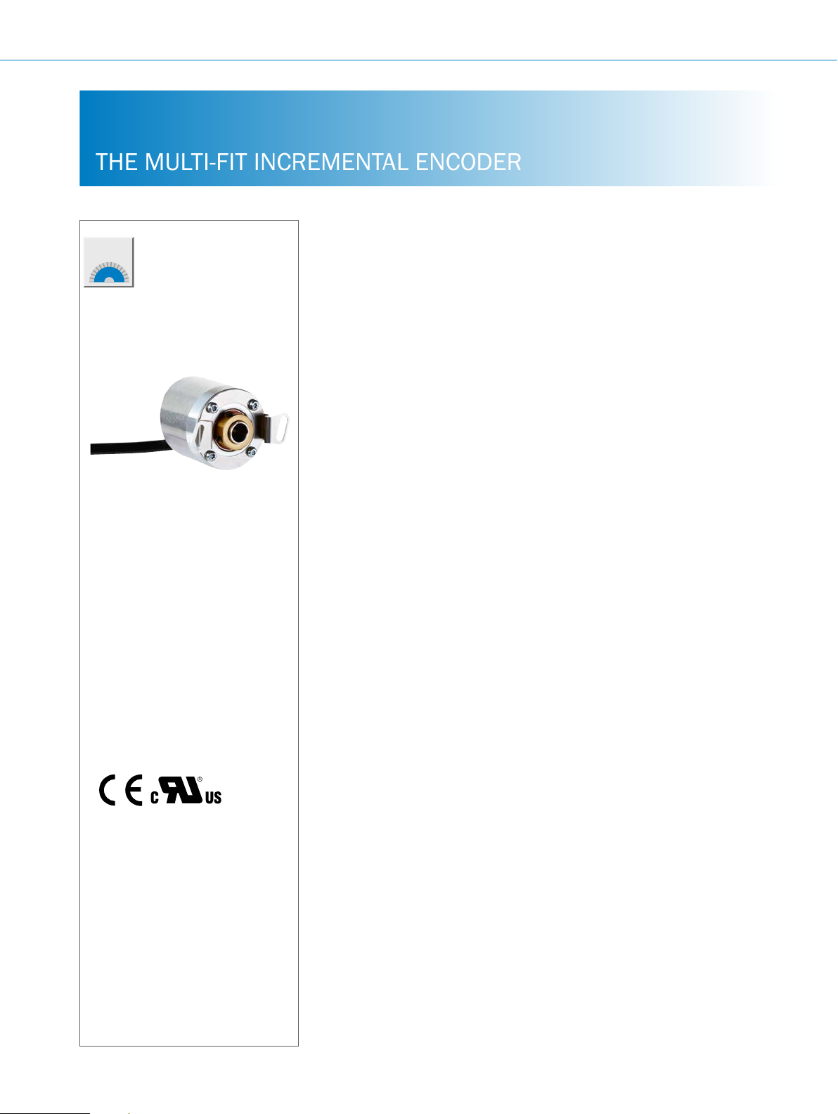
DBS36 Core INCREMENTAL ENCODERS
Product description
The DBS36 Core incremental encoder
features impressively high mechanical
exibility, excellent technical properties,
and a number of variations. A blind
hollow shaft with a shaft diameter of up
to 8 mm and a face mount ange with
6 mm and 1/4" solid shaft are available.
The design with face mount ange
offers 2 different anges with 6 differ-
ent mounting hole patterns and a servo
At a glance
• Connection with universal cable outlet
• Designs with blind hollow shaft or
face mount ange with solid shaft
• Face mount ange with 6 mounting
hole patterns and servo groove
• Hollow shaft with universal stator
coupling
groove for mounting with servo clamps.
The hollow shaft design has a universal
stator coupling that can be used for
multiple typical mounting hole circles. All
models have compact dimensions and a
universal cable outlet that allows for cables to run in an axial or radial direction.
• Compact housing diameter of 37 mm
with compact construction depth,
• Electrical interfaces: TTL/RS-422,
HTL/Push Pull and Open Collector
NPN
• Number of lines: 10 to 2,500
• Temperature range: –20 °C... +85 °C
• Enclosure rating: IP 65
Additional information
Fields of application . . . . . . . . . . . . F-83
Detailed technical data. . . . . . . . . . F-83
Type code. . . . . . . . . . . . . . . . . . . . . F-85
Ordering information. . . . . . . . . . . . F-87
Interfaces.....................F-90
Dimensional drawings . . . . . . . . . . F-91
Proposed tting . . . . . . . . . . . . . . . . F-93
PIN assignment. . . . . . . . . . . . . . . . F-93
Recommended accessories. . . . . . F-94
Your benets
• The universal cable outlet allows for
use in tight spaces and for exible
cabling
• Face mount ange with various
mounting hole patterns provides high
exibility when mounting in existing
and new applications
• Face mount ange with servo groove
makes mounting with servo clamps
possible
• The universal stator coupling of the
DBS36 Core allows for easy device
replacement without adapting the
application
• Shafts in metric and US design en-
able worldwide use.
• The high exibility of the mechanical
interface of the encoder and the available accessories allow for the use of a
single design in many applications
• Long-term and reliable operation
thanks to a high enclosure rating,
temperature resistance and bearing
lifetime
F-82
ENCODERS | SICK 8015560/2015-09-01
Subject to change without notice
Page 2

Fields of application
There are numerous application possibilities for positioning and
speed measurement, such as in the textile industry, propulsion
Detailed technical data
Performance
INCREMENTAL ENCODERS DBS36 Core
technology, storage and conveyors, packaging machines, printing presses, glass industry, and elevators
Pulses per revolution
Measurement step
Measurement step deviation
Error limits
Duty cycle
Initialization time
Mechanical data
Mechanical design
Shaft diameter
Solid shaft, face mount ange 6 mm x 12 mm
Blind hollow shaft 8 mm (shaft diameter 1/4", 6 mm, 5 mm via collet possible – (see Accessories))
Mass
Shaft material
Flange material
Housing material
Cable material
Start up torque
Operating torque
Permissible shaft movement, axial static/
dynamic
Blind hollow shaft ± 0.5 mm, ± 0.2 mm
Permissible shaft movement, radial static/
dynamic
Blind hollow shaft ± 0.3 mm, ± 0.1 mm
Permissible shaft load, radial/axial
Solid shaft, face mount ange 40 N (radial)
Operating speed
Maximum operating speed
Rotor moment of inertia
Solid shaft, face mount ange 0.6 gcm²
Blind hollow shaft 0.8 gcm²
Bearing lifetime
Max. angular acceleration
1)
Higher values possible by limiting the overall service life.
2)
Solid shaft: Self-warming 3.3 K per 1,000 rpm.
3)
Hollow shaft: Self-warming 4.7 K per 1,000 rpm.
4)
No continuous operation. Signal quality is degraded.
1)
10 ... 2,500
90° electric/pulse
± 18°/pulses per revolution
± 54°/pulses per revolution
≤ 0.5 ± 5%
< 3 ms
Solid shaft, face mount ange
Blind hollow shaft
1/4" x 15.5 mm
150 g (with connecting cable)
Stainless steel
Aluminum
Aluminum
PVC
0.5 Ncm (+20 °C)
0.4 Ncm (+20 °C)
20 N (axial)
6,000/min
6,000/min
8,000 rpm
2 x 10^9 revolutions
≤ 500,000 rad/s²
2)
3)
4)
F
Subject to change without notice
ENCODERS | SICK8015560/2015-09-01
F-83
Page 3

DBS36 Core INCREMENTAL ENCODERS
Electrical data
F
Electrical interface
4,5 V ... 5,5 V, TTL/RS422
7 V ... 30 V, TTL/RS422
7 V ... 30 V, HTL Push Pull
7 V… 27 V, HTL Push Pull, 3 channel
4.5 V ... 5.5 V, Open Collector NPN
4.5 V ... 30 V, Open Collector NPN
Connection type
Cable, 5 or 8-wire, universal, 0.5 m
Cable, 5 or 8-wire, universal, 1.5 m
Cable, 5 or 8-wire, universal, 3 m
Cable, 5 or 8-wire, universal, 5 m
Cable, 5 or 8-wire, universal, 10 m
2)
2)
2)
2)
2)
Cable, 8-wire with male connector M12, universal, 0.5 m
Cable, 8-wire with male connector M23, universal, 0.5 m
1)
Operating current without load
4.5 V...5.5 V, TTL/RS422 ≤ 50 mA
4.5 V ... 5.5 V, Open Collector NPN ≤ 50 mA
Max. power consumption without load
7 V ... 30 V, TTL/RS422 < 0.5 W
7 V ... 30 V, HTL Push Pull < 0.5 W
7 V ... 27 V, HTL Push Pull < 0.5 W
4.5 V ... 30 V, Open Collector NPN < 0.5 W
Max. load current
Open Collector ≤ 30 mA
TTL/HTL ≤ 30 mA
Maximum output frequency
Reference signal, number
Reference signal, position
300 kHz
1
90° electric, logically gated with A and B
Reverse polarity protection
4,5 V ... 5,5 V, TTL/RS422 –
7 V ... 30 V, TTL/RS422
7 V ... 30 V, HTL Push Pull
7 V ... 27 V, HTL Push Pull
4.5 V ... 5.5 V, Open Collector NPN
4.5 V ... 30 V, Open Collector NPN
Short-circuit protection of outputs
3)
4,5 V ... 5,5 V, TTL/RS422
7 V ... 30 V, TTL/RS422
7 V ... 30 V, HTL Push Pull
7 V ... 27 V, HTL Push Pull
4.5 V ... 5.5 V, Open Collector NPN
4.5 V ... 30 V, Open Collector NPN
MTTFd: mean time to dangerous failure
1)
M23 male connector for central mounting
2)
Number of wires depending on electrical interface: Interface A, C, E: 8-wire; Interface G, P, R: 5-wire.
3)
Short-circuit protection is only guaranteed when Us and GND are connected correctly.
4)
This product is a standard product and does not constitute a safety component as dened in the Machinery Directive. Calculation based on nominal load of de-
vices, average ambient temperature 40 °C, frequency of use 8760 h/a. All electronic failures are considered hazardous. For more information, see document no.
8015532.
l
l
l
l
l
l
l
l
l
l
l
600 years (EN ISO 13849-1)
4)
F-84
ENCODERS | SICK 8015560/2015-09-01
Subject to change without notice
Page 4
Ambient data
INCREMENTAL ENCODERS DBS36 Core
EMC
Enclosure rating
Permissible relative humidity
Operating temperature range
4,5 V ... 5,5 V, TTL/RS422 –20 °C ... +85 °C (–35 °C ... +95 °C upon request)
7 V ... 30 V, TTL/RS422 –20 °C ... +85 °C (–35 °C ... +95 °C upon request)
7 V ... 30 V, HTL Push Pull –20 °C ... +85 °C (–35 °C ... +95 °C upon request)
7 V ... 27 V, HTL Push Pull –20 °C ...+70 °C
4.5 V ... 5.5 V, Open Collector NPN –20 °C ... +85 °C (–35 °C ... +95 °C upon request)
4.5 V ... 30 V, Open Collector NPN –20 °C ... +85 °C (–35 °C ... +95 °C upon request)
Storage temperature range
Resistance to shocks
Resistance to vibrations
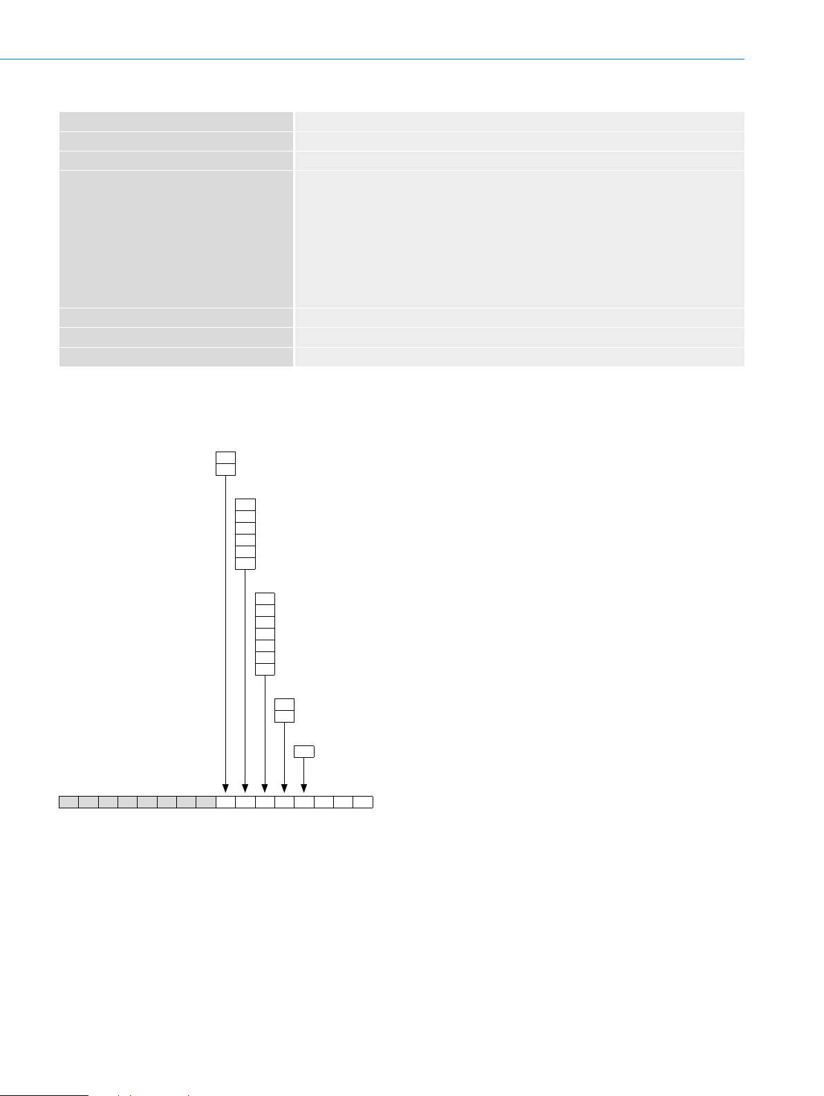
Type code
Solid shaft
According to EN 61000-6–2 and EN 61000-6–3 (class A)
IP 65
90% (condensation of optical surfaces not permitted)
–40 °C ... +100 °C, without packaging
100 g /6 ms (EN 60068-2-27)
20 g, 10 Hz ... 2,000 Hz (EN 60068-2-6)
Mechanical design
3 Face mount ange, solid shaft, Ø 6 mm, length 12 mm
8 Face mount ange, solid shaft, Ø 1/4" mm, length 15.5 mm
Electrical interface
A 4.5 … 5.5 V, TTL/RS-422, 6 channel
C 7 … 30 V, TTL/RS-422, 6 channel
E 7 … 30 V, HTL Push Pull, 6 channel
G 7 … 27 V, HTL Push Pull, 3 channel
P 4.5 … 5.5 V, Open Collector NPN, 3 channel
R 4.5 … 30 V, Open Collector NPN, 3 channel
F
Connection type
J Cable, 5 or 8-wire, universal, 0.5 m
K Cable, 5 or 8-wire, universal, 1.5 m
L Cable, 5 or 8-wire, universal, 3 m
M Cable, 5 or 8-wire, universal, 5 m
N Cable, 5 or 8-wire, universal, 10 m
P Cable, 8-wire universal, 0.5 m, with male connector M12, 8-pin
Q Cable, 8-wire universal, 0.5 m, with male connector M23, 12-pin
Flange design
0
Face mount ange, standard hole pattern
A
Face mount ange, hole pattern A (only with shaft S3)
Resolution
0010... 2,500 pulses per revolution possible. For pulses see “Pulses per revolution”
D B S 3 6 E - S
1)
Number of wires depending on electrical interface: Interface A, C, E: 8-wire; Interface G, P, R: 5-wire.
2)
Other pulse on request.
1)
1)
1)
1)
1)
2)
Subject to change without notice
ENCODERS | SICK8015560/2015-09-01
F-85
Page 5
DBS36 Core INCREMENTAL ENCODERS
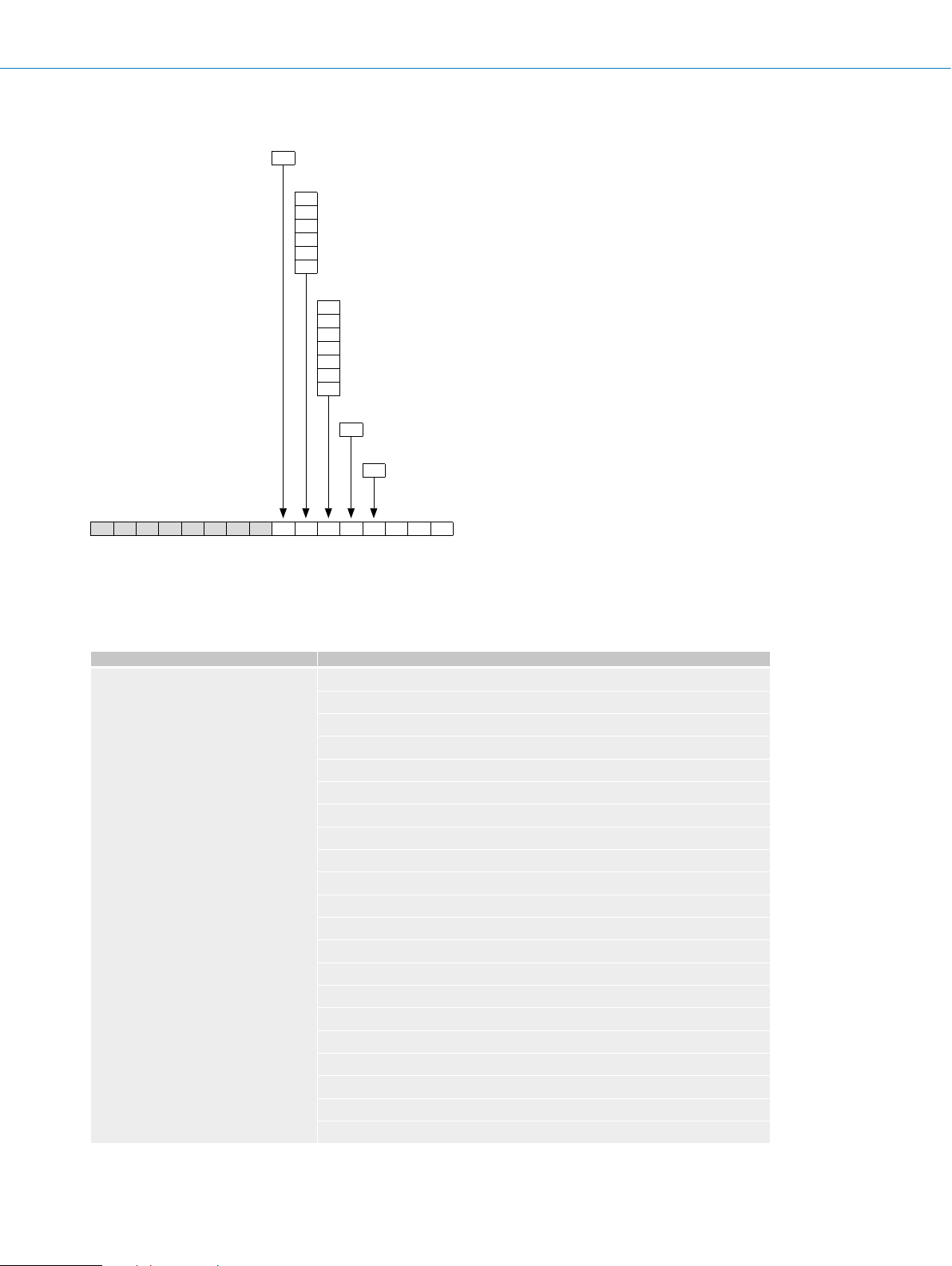
Hollow shaft
Mechanical design
B Blind hollow shaft, Ø 8 mm
Electrical interface
A 4.5 … 5.5 V, TTL/RS-422, 6 channel
1)
C 7 … 30 V, TTL/RS-422, 6 channel
E 7 … 30 V, HTL Push Pull, 6 channel
G 7 … 27 V, HTL Push Pull, 3 channel
P 4.5 … 5.5 V, Open Collector NPN, 3 channel
R 4.5 … 30 V, Open Collector NPN, 3 channel
Connection type
J Cable, 5 or 8-wire, universal, 0.5 m
K Cable, 5 or 8-wire, universal, 1.5 m
L Cable, 5 or 8-wire, universal, 3 m
M Cable, 5 or 8-wire, universal, 5 m
N Cable, 5 or 8-wire, universal, 10 m
2)
2)
2)
2)
2)
P Cable, 8-wire universal, 0.5 m, with male connector M12, 8-pin
Q Cable, 8-wire universal, 0.5 m, with male connector M23, 12-pin
Stator coupling
0
Standard stator coupling
Resolution
0010... 2,500 pulses per revolution possible. For pulses see “Pulses per revolution”
D B S 3 6 E - S
1)
Shaft diameter 1/4", 6 mm, 5 mm via collet possible (see Accessories).
2)
Number of wires depending on electrical interface: Interface A, C, E: 8-wire; Interface G, P, R: 5-wire.
3)
Other pulse on request.
3)
F
Pulses per revolution
E
Pulses per revolution
1)
Additional available upon request.
1)
0010
0020
0050
0100
0120
0125
0200
0250
0256
0300
0360
0400
0500
0512
0600
1000
1024
1200
2000
2048
2500
F-86
ENCODERS | SICK 8015560/2015-09-01
Subject to change without notice
Page 6

Ordering information
Solid shaft, face mount ange
• Shaft diameter: 6 mm
INCREMENTAL ENCODERS DBS36 Core
Electrical interface Voltage range Connection type Range of pulses per
revolution
100 DBS36E-S3AJ00100 1061237
360 DBS36E-S3AJ00360 1061238
400 DBS36E-S3AJ00400 1061239
500 DBS36E-S3AJ00500 1061240
1,024 DBS36E-S3AJ01024 1060867
100 DBS36E-S3AK00100 1060535
360 DBS36E-S3AK00360 1060536
400 DBS36E-S3AK00400 1060537
500 DBS36E-S3AK00500 1060538
1,000 DBS36E-S3AK01000 1060539
1,024 DBS36E-S3AK01024 1060144
2,048 DBS36E-S3AK02048 1058602
2,500 DBS36E-S3AK02500 1060268
500 DBS36E-S3CJ00500 1066387
100 DBS36E-S3CK00100 1063772
500 DBS36E-S3CK00500 1062944
1,000 DBS36E-S3CK01000 1064515
1,024 DBS36E-S3CK01024 1067267
2,048 DBS36E-S3CK02048 1059906
2,500 DBS36E-S3CK02500 1068997
100 DBS36E-S3EJ00100 1061242
360 DBS36E-S3EJ00360 1061243
400 DBS36E-S3EJ00400 1061244
500 DBS36E-S3EJ00500 1061245
1,000 DBS36E-S3EJ01000 1061246
1,024 DBS36E-S3EJ01024 1061247
100 DBS36E-S3EK00100 1060540
200 DBS36E-S3EK00200 1062679
256 DBS36E-S3EK00256 1065241
360 DBS36E-S3EK00360 1060541
400 DBS36E-S3EK00400 1060542
500 DBS36E-S3EK00500 1060543
1,000 DBS36E-S3EK01000 1060544
1,024 DBS36E-S3EK01024 1060545
2,048 DBS36E-S3EK02048 1059907
2,500 DBS36E-S3EK02500 1061133
2,048 DBS36E-S3EP02048 1068156
4.5 V ... 5.5 V
TTL/RS422
7 V ... 30 V
HTL/Push Pull 7 V ... 30 V
Cable, 8-wire universal,
0.5 m
Cable, 8-wire, universal,
1.5 m
Cable, 8-wire universal,
0.5 m
Cable, 8-wire, universal,
1.5 m
Cable, 8-wire, universal,
0.5 m
Cable, 8-wire, universal,
1.5 m
Cable, 8-wire with male
connector M12, univer-
sal, 0.5 m
Type Part no.
F
Subject to change without notice
ENCODERS | SICK8015560/2015-09-01
F-87
Page 7

DBS36 Core INCREMENTAL ENCODERS
Blind hollow shaft
• Shaft diameter: 8 mm
F
Electrical interface Voltage range Connection type Range of pulses
per revolution
360 DBS36E-BBAJ00360 1061249
400 DBS36E-BBAJ00400 1061250
500 DBS36E-BBAJ00500 1061251
1,000 DBS36E-BBAJ01000 1061252
1,024 DBS36E-BBAJ01024 1060868
100 DBS36E-BBAK00100 1060524
360 DBS36E-BBAK00360 1060525
400 DBS36E-BBAK00400 1060526
500 DBS36E-BBAK00500 1060527
1,000 DBS36E-BBAK01000 1060528
1,024 DBS36E-BBAK01024 1060147
2,048 DBS36E-BBAK02048 1058603
2,500 DBS36E-BBAK02500 1061235
100 DBS36E-BBCK00100 1060148
1,000 DBS36E-BBCK01000 1065589
2,048 DBS36E-BBCP02048 1062240
100 DBS36E-BBEJ00100 1061253
360 DBS36E-BBEJ00360 1061254
400 DBS36E-BBEJ00400 1061255
500 DBS36E-BBEJ00500 1061256
1,000 DBS36E-BBEJ01000 1061257
1,024 DBS36E-BBEJ01024 1061258
2,000 DBS36E-BBEJ02000 1068715
2,500 DBS36E-BBEJ02500 1062490
100 DBS36E-BBEK00100 1060529
200 DBS36E-BBEK00200 1064320
360 DBS36E-BBEK00360 1060530
400 DBS36E-BBEK00400 1060531
500 DBS36E-BBEK00500 1060532
1,000 DBS36E-BBEK01000 1060533
1,024 DBS36E-BBEK01024 1060534
2,048 DBS36E-BBEK02048 1059910
100 DBS36E-BBEP00100 1065770
200 DBS36E-BBEP00200 1068935
4.5 V ... 5.5 V
TTL/RS422
7 V ... 30 V
HTL/Push Pull 7 V ... 30 V
Cable, 8-wire universal,
0.5 m
Cable, 8-wire, universal,
1.5 m
Cable, 8-wire, universal,
1.5 m
Cable, 8-wire with male
connector M12, univer-
sal, 0.5 m
Cable, 8-wire universal,
0.5 m
Cable, 8-wire, universal,
1.5 m
Cable, 8-wire with male
connector M12, univer-
sal, 0.5 m
Type Part no.
F-88
ENCODERS | SICK 8015560/2015-09-01
Subject to change without notice
Page 8

INCREMENTAL ENCODERS DBS36 Core
Electrical interface Voltage range Connection type Range of pulses
per revolution
200 DBS36E-BBPK00200 1065144
Cable, 8-wire, universal,
1.5 m
Open collector 4.5 V ... 5.5 V
Cable, 8-wire with male
connector M12, univer-
sal, 0.5 m
500 DBS36E-BBPK00500 1064120
1,000 DBS36E-BBPK01000 1067836
2,048 DBS36E-BBPK02048 1059911
2,500 DBS36E-BBPK02500 1065791
360 DBS36E-BBAP00360 1067379
500 DBS36E-BBAP00500 1068192
1,000 DBS36E-BBAP01000 1066259
1,024 DBS36E-BBAP01024 1062784
2,500 DBS36E-BBAP02500 1062785
Type Part no.
F
Subject to change without notice
ENCODERS | SICK8015560/2015-09-01
F-89
Page 9

DBS36 Core INCREMENTAL ENCODERS
Interfaces
Signal outputs for electrical interfaces TTL and HTL
Measuring step
CW with view on the encoder shaft in direction “A”, compare
dimensional drawing.
Interfaces G, P, R only for channels A, B, Z.
Supply voltage Output
4.5 V ... 5.5 V TTL/RS422
7 V ... 30 V TTL/RS422
7 V ... 30 V HTL Push Pull
7 V ... 27 V HTL Push Pull, 3 channel
4.5 V ... 5.5 V Open Collector NPN
4.5 V ... 30 V Open Collector NPN
F
F-90
ENCODERS | SICK 8015560/2015-09-01
Subject to change without notice
Page 10

Dimensional drawings (dimensions in mm)
Ø 36.7
PCD
3x M3 depht 7 mm
(0.28)
Ø 36.7
PCD
4x M3 depht 5 mm
(0.20)
Solid shaft, face mount ange, shaft 6 mm x 12 mm, standard hole pattern
INCREMENTAL ENCODERS DBS36 Core
3x 120° @ 28 mm (1.10) PCD
3x M3 depht 7 mm
(0.28)
3x 120° @ 30 mm (1.18) PCD
Ø 44.5
(1.75)
(1.44)
(0.79)
Ø 20 f8
5.6
(0.24)
Ø 6 f7
(0.22)
3
(1.12)
2.5
(0.10)
12
(0.47)
8.5
(0.33)
6
(0.24)
35.5
(1.40)
Ø 33.8
2.1
(0.08)
Ø 37
(1.33)
(1.46)
0.5
(0.02)
Solid shaft, face mount ange, shaft 6 mm x 12 mm, Type A ange design hole pattern
35.5
3
(1.12)
(1.40)
0.5
(0.02)
4x 90° @ 26 mm (1.02) PCD
4x M3 depth 7 mm (0.28)
4x 90° @ 30 mm (1.18)
3 x 120°
3x M3 depth 5 mm
3x 120° @ 26 mm (1.02)
F
(0.20)
2x M3 depht 7 mm
(0.28)
2x 180° @ 28 mm (1.10) PCD
6
(0.24)
Ø 33.8
2.1
(0.08)
Ø 37
(1.33)
(1.46)
Ø 44.5
(1.75)
3 x 120°
(1.44)
(0.79)
(0.24)
Ø 6 f7
Ø 20 f8
2.5
(0.10)
12
(0.47)
5.6
(0.22)
8.5
(0.33)
Subject to change without notice
ENCODERS | SICK8015560/2015-09-01
F-91
Page 11

DBS36 Core INCREMENTAL ENCODERS
Ø 36.7
45.4
Solid shaft, face mount ange, shaft 1/4" x 15.5 mm, standard hole pattern
PCD
(0.28)
(1.10)
3x M3 depth 7 mm
3x 120° @ 30 mm
F
35.5
(1.40)
6
(0.24)
2.1
(0.08)
Ø 33.8
(0.02)
(1.33)
Ø 37
(1.46)
0.5
-0.005
-0.020
Ø 6.35
(1.44)
(0.25)
(0.39)
(0.79)
Ø 20 f8
3
(0.12)
15.5
(0.61)
10
2.5
(0.10)
Blind hollow shaft, cable outlet
(7.7)
(0.30)
1
(0.04)
(1.79)
0.5
(0.02)
(0.28)
(1.18)
PCD
4x M2.5 screw
@ 30 mm
3x M3 depth 7 mm
3x 120° @ 28 mm
4x M3 depth 7 mm
4x 90° @ 30 mm
(1.18) PCD
3.2
(0.13)
(0.28)
(1.18)
20°
PCD
Ø 42
(1.65)
Ø 46
(1.81)
2x M3 set screw
Hexagon socket
screw size 1,5
(0.31)
Ø 8 F7
21.5
(0.85)
Ø 37
(1.46)
F-92
ENCODERS | SICK 8015560/2015-09-01
Subject to change without notice
Page 12

Proposed tting
–0.015
0
Ø X
min. 6
max. 21
Diameter X Encoder Collet
5 mm
6 mm 2056390
1/4“ upon request
8 mm not required
DBS36E-BB
PIN assignment
INCREMENTAL ENCODERS DBS36 Core
2066991
Wire color Pin 8-pole
for M12
brown1 6Not connectedA- Signal wire
white 25AASignal wire
black 31Not connectedB- Signal wire
pink 48BBSignal wire
Yellow5 4 Not connectedZ- Signal wire
purple 6 3 ZZSignal wire
blue7 10 GND GND
Red8 12 +Us+Us Supply voltage
--9Not connectedNot connectedNot connected
--2Not connectedNot connectedNot connected
--11 Not connectedNot connectedNot connected
--7Not connectedNot connectedNot connected
Shield Shield Shield Shield Shield
Pin 12-pole
for M23
Signal
HTL / OC 3-channel
Signal
TTL / HTL 6-channel
Explanation
Ground connection
of the encoder
Shield (connected
with housing on the
encoder side)
F
Subject to change without notice
ENCODERS | SICK8015560/2015-09-01
F-93
Page 13

DBS36 Core INCREMENTAL ENCODERS
Recommended accessories
Mounting systems
Mounting brackets and plates
Mounting bracket
Figure Brief description Type Part no.
F
Mounting bracket for encoder with centering hub 20 mm, including mounting kit for face
mount ange
BEF-WF-20 2066393
Flanges
Flange plate
Figure Brief description Type Part no.
Flange adapter, adaption of face mount ange with centering hub 20 mm to 33 mm
servo ange, aluminum
BEF-FA-020-033 2066312
Other mounting accessories
Measuring wheels and measuring wheel systems
Figure Brief description Type Part no.
Measuring wheel with O-ring (NBR70) for 6 mm solid shaft, circumference 200 mm BEF-MR006020R 2055222
Measuring wheel with O-ring (NBR70) for 6 mm solid shaft, circumference 300 mm BEF-MR006030R 2055634
O-ring for measuring wheels (circumference 200 mm) BEF-OR-053-040 2064061
O-ring for measuring wheels (circumference 300 mm) BEF-OR-083-050 2064076
Servo clamps
Figure Brief description Type Part no.
Servo clamps, small, for servo anges (clamps, eccentric fastener), 3 pcs., without
mounting material
BEF-WK-RESOL 2039082
Miscellaneous
Figure Brief description Type Part no.
Two-sided stator coupling, screw hole diameter 42 - 46 mm, slot width 3.2 mm BEF-DS-DBS36 2066301
Shaft adaptation
Collets and clamping rings
Figure Brief description Type Part no.
Collet for blind hollow shaft, shaft diameter 5 mm, external diameter 8 mm SPZ-005-AD-A 2066991
Collet for blind hollow shaft, shaft diameter 6 mm, external diameter 8 mm SPZ-006-DD36-A 2056390
F-94
ENCODERS | SICK 8015560/2015-09-01
Subject to change without notice
Page 14
INCREMENTAL ENCODERS DBS36 Core
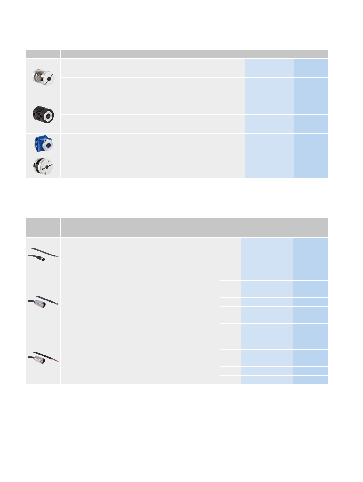
Shaft couplings
Figure Brief description Type Part no.
Bellows coupling, shaft diameter 6 mm / 6 mm, maximum shaft offset: radial
± 0.25 mm, axial ± 0.4 mm, angular +/- 4°; max. speed 10,000 rpm, –30 °C to
+120 °C, max. torque 80 Ncm; material: stainless steel bellows, aluminum hub
Bellows coupling, shaft diameter 6 mm / 10 mm, maximum shaft offset: radial
± 0.25 mm, axial ± 0.4 mm, angular +/- 4°; max. speed 10,000 rpm, –30 °C to
+120 °C, max. torque 80 Ncm; material: stainless steel bellows, aluminum hub
Bar coupling, shaft diameter 6 mm / 6 mm, maximum shaft offset: radial ± 0.3 mm,
axial ± 0.2 mm, angle ± 3°; max. speed 10,000 rpm, –10° to +80 °C, max. torque
80 Ncm; material: ber-glass reinforced polyamide, aluminum hub
Bar coupling, shaft diameter 6 mm / 8 mm, maximum shaft offset radial ± 0.3 mm, ax-
ial ± 0.2 mm, angle ± 3°, max. speed 10,000 rpm, torsion spring rigidity 38 Nm/wheel;
material: ber-glass reinforced polyamide, aluminum hub
Double-loop coupling, shaft diameter 6 mm/10 mm, maximum shaft offset: radial
± 2.5 mm, axial ± 3 mm, angular ± 10°; max. speed 3,000 rpm, –30 °C to +80 °C,
max. torque 1.5 Nm; material: polyurethane, galvanized steel ange
Spring washer coupling, shaft diameter 6 mm/10 mm, maximum shaft offset: radial
± 0.3 mm, axial ± 0.4 mm, angular ± 2.5°; max. speed 12,000 rpm, –10 °C to +80 °C,
max. torque 60 Ncm; material: aluminum ange, ber-glass reinforced polyamide mem-
brane and tempered steel coupling pin
Connectivity
KUP-0606-B 5312981
KUP-0610-B 5312982
KUP-0606-S 2056406
KUP-0608-S 5314179
KUP-0610-D 5326697
KUP-0610-F 5312985
Plug connectors and cables
Connecting cables with female connector
Figure Brief description
Head A: female connector, M12, 8-pin, straight
Head B: cable
Cable: suitable for drag chain, PVC, shielded, 4 x 2 x 0.25 mm², Ø 7.0 mm
Head A: female connector, M23, 12-pin, straight
Head B: cable
Cable: incremental, PUR, shielded, 4 x 2 x 0.25 mm² + 2 x 0.5 mm²
+ 1 x 0.14 mm², Ø 7.8 mm
Head A: female connector, M23, 12-pin, straight
Head B: cable
Cable: incremental, suitable for drag chain, PUR, shielded, 4 x 2 x 0.25 mm²
+ 2 x 0.5 mm² + 1 x 0.14 mm², Ø 7.8 mm
1)
Warning! Only in combination with electrical interfaces A, C, E and P.
1)
Length
Type Part no.
of
cable
2 m DOL-1208-G02MAC1
5 m DOL-1208-G05MAC1
10 m DOL-1208-G10MAC1
20 m DOL-1208-G20MAC1
2 m DOL-2312-G02MLA3
7 m DOL-2312-G07MLA3
10 m DOL-2312-G10MLA3
1)
15 m DOL-2312-G15MLA3
20 m DOL-2312-G20MLA3
25 m DOL-2312-G25MLA3
30 m DOL-2312-G30MLA3
1.5 m DOL-2312-G1M5MA3
3 m DOL-2312-G03MMA3
5 m DOL-2312-G05MMA3
10 m DOL-2312-G10MMA3
20 m DOL-2312-G20MMA3
30 m DOL-2312-G30MMA3
6032866
6032867
6032868
6032869
2030682
2030685
2030688
2030692
2030695
2030699
2030702
2029212
2029213
2029214
2029215
2029216
2029217
F
Subject to change without notice
ENCODERS | SICK8015560/2015-09-01
F-95
Page 15

DBS36 Core INCREMENTAL ENCODERS
Female connectors (ready to assemble)
Figure Brief description Type Part no.
Head A: female connector, M12, 8-pin, straight, A encoded, shielded, for cable diameter
4 mm ... 8 mm
Head B: -
Operating temperature: –40 °C ... +85 °C
Head A: female connector, M23, 12-pin, straight, shielded, for cable diameter
5.5 mm ... 10.5 mm
Head B: Operating temperature:
–20 °C ... +130 °C
Head A: female connector, M23, 12-pin, angled, shielded, for cable diameter
4.2 mm ... 6.6 mm
Head B: Operating temperature:
–20 °C ... +130 °C
Head A: female connector, M23, 12-pin, straight, shielded, for cable diameter
5.5 mm ... 10.5 mm
Head B: Operating temperature:
–40 °C ... +125 °C
Cables (ready to assemble)
DOS-1208-GA01
DOS-2312-G
DOS-2312-W01
DOS-2312-G02
6045001
6027538
2072580
2077057
F
Figure Brief description Length
Type Part no.
of
cable
Head A: cable
Head B: cable
Cable: suitable for drag chain, PUR, halogen-free, shielded, 4 x 2 x 0.15 mm²,
Ø 5.6 mm
Head A: cable
Head B: cable
Cable: PUR, shielded, 4 x 2 x 0.25 mm² + 2 x 0.5 mm² + 1 x 0.14 mm²,
Ø 7.5 mm
Head A: cable
Head B: cable
Cable: suitable for drag chain, PUR, halogen-free, shielded, 4 x 2 x 0.25 mm²
+ 2 x 0.5 mm² + 2 x 0.14 mm², Ø 7.8 mm
Head A: cable
Head B: cable
Cable: suitable for drag chain, PUR, halogen-free,
shielded, UV and saltwater resistant, 4 x 2 x
0.25 mm² + 2 x 0.5 mm² +
2 x 0.14 mm², Ø 7.8 mm
By the
meter
LTG-2308-MWENC 6027529
LTG-2411-MW 6027530
LTG-2512-MW 6027531
LTG-2612-MW 6028516
Male connector (ready to assemble)
Figure Brief description Type Part no.
Head A: male connector, M12, 8-pin, straight, A encoded, shielded, for cable diameter
4 mm ... 8 mm
Head B: Operating temperature:
–40 °C ... +85 °C
Head A: male connector, M23, 12-pin, straight, shielded, for cable diameter
5.5 mm ... 10.5 mm
Head B:
Operating temperature: –20 °C ... +130 °C
Head A: male connector, M23, 12-pin, straight, for cable diameter 5.5 mm ... 10.5 mm
Head B: Operating temperature:
–40 °C ... +125 °C
- For additional accessories, please see page K-668 onwards
STE-1208-GA01 6044892
STE-2312-G 6027537
STE-2312-G01 2077273
F-96
ENCODERS | SICK 8015560/2015-09-01
Subject to change without notice
Page 16

INCREMENTAL ENCODERS DBS36 Core
F
Subject to change without notice
ENCODERS | SICK8015560/2015-09-01
F-97
 Loading...